nasa’s pursuit of low-noise propulsion for low-boom
TRANSCRIPT
1
NASA’s Pursuit of Low-Noise Propulsion for Low-Boom Commercial Supersonic Vehicles
James Bridges, Clifford A. Brown, Jonathan SeidelNASA Glenn Research Center
AIAA SciTech 08 January 2018
Supported byNASA Advanced Air Vehicles Program/Commercial Supersonic Technology ProjectAnd by many, many researchers working with NASA on supersonic aircraft noise.

2
Airport Noise—A Commercial Supersonics ChallengeCu
m E
PNdB
re C
hapt
er 3
Concorde60
30
0
-30
-601970 1980 1990 2000 2010 2020
Year of Certification
NASA Supersonics N+2 Goal“Stage 4 – 10 EPNdB”
For Lockheed 1044 aircraft, Stage 4 – 10 EPNdB equates to 92.7 EPNdB at Lateral observer. This is our Noise Goal.
3
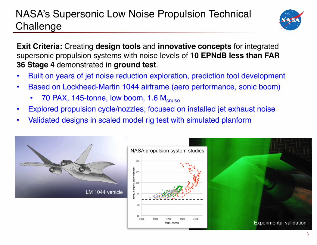
NASA’s Supersonic Low Noise Propulsion Technical Challenge
Exit Criteria: Creating design tools and innovative concepts for integrated supersonic propulsion systems with noise levels of 10 EPNdB less than FAR 36 Stage 4 demonstrated in ground test. • Built on years of jet noise reduction exploration, prediction tool development• Based on Lockheed-Martin 1044 airframe (aero performance, sonic boom)
• 70 PAX, 145-tonne, low boom, 1.6 Mcruise
• Explored propulsion cycle/nozzles; focused on installed jet exhaust noise• Validated designs in scaled model rig test with simulated planform
LM 1044 vehicle
NASA propulsion system studies
Experimental validation

4
Innovative Nozzle Concepts Explored
2011 2012 2013 2014 2015
Mixer-Ejector Twin Jet Shielding 3-Stream Offset Split Velocity Profile
Plasma Excitation High Aspect Ratio Inverted Velocity Profile
Acoustic benefits documented in databases for modeling used in design.
5
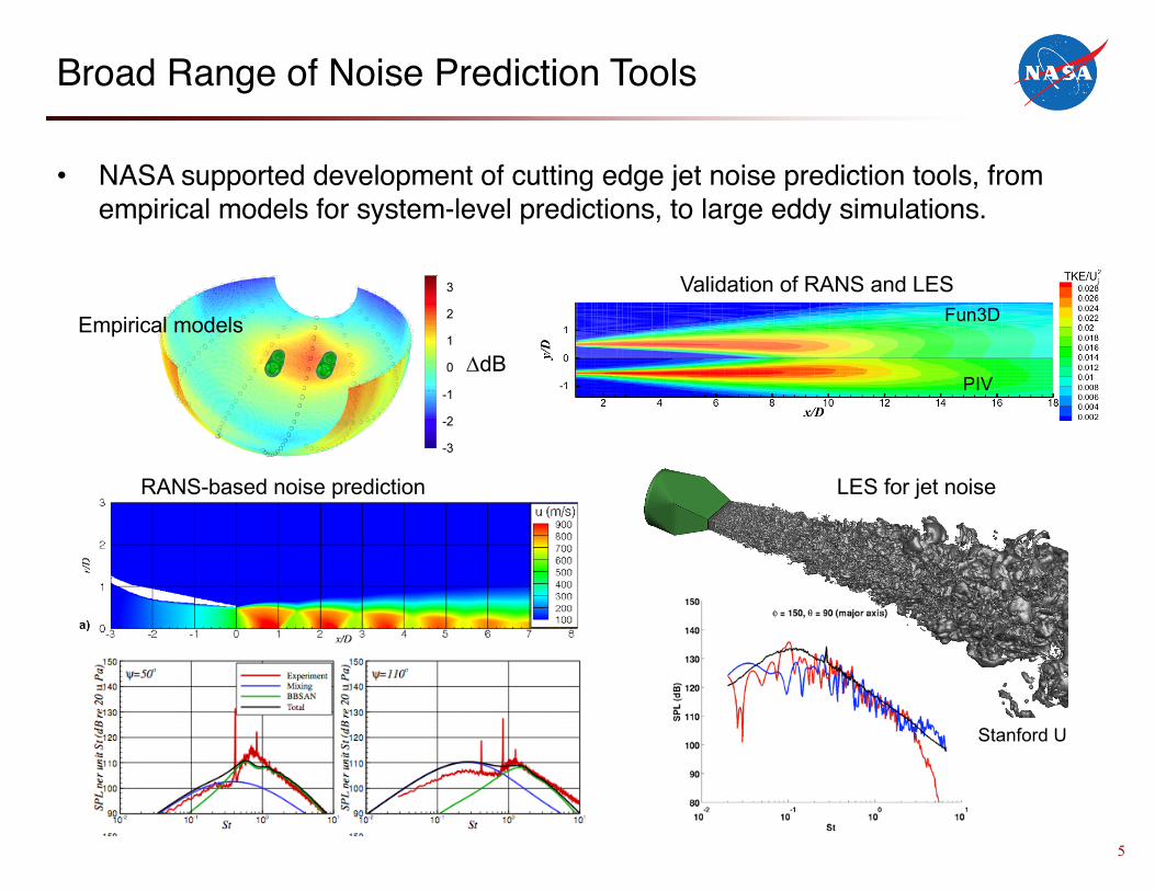
Broad Range of Noise Prediction Tools
• NASA supported development of cutting edge jet noise prediction tools, from empirical models for system-level predictions, to large eddy simulations.
RANS-based noise prediction
Fun3D
PIV
Validation of RANS and LES
LES for jet noise
Stanford U
Ma=0.9, cold Twin Jets at Z4Strouhal Number = 0.33
D S
PL (d
B)
-3
-2
-1
0
1
2
3
3
2
1
0
-1
-2
-3
DdB
Empirical models
6
90
95
100
105
110
115
120
125
3-En
gine
Lat
eral
EPN
L, N
omin
al N
ozzl
e
Range
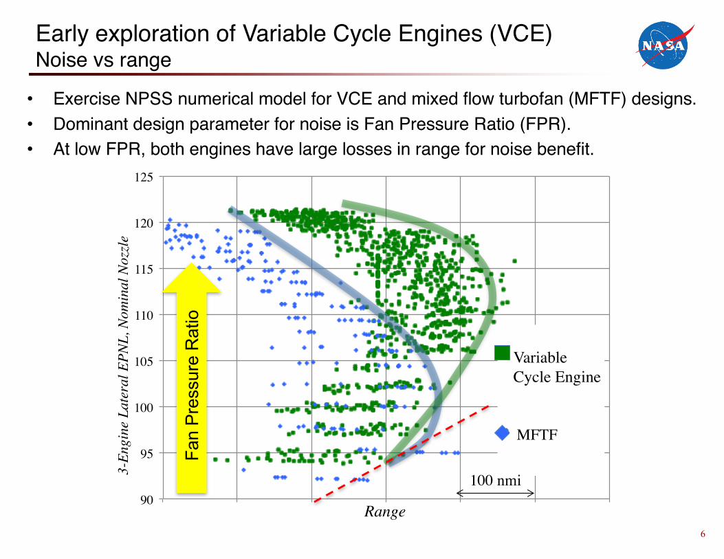
Variable Cycle Engine
Conventional
Early exploration of Variable Cycle Engines (VCE)Noise vs range
• Exercise NPSS numerical model for VCE and mixed flow turbofan (MFTF) designs.• Dominant design parameter for noise is Fan Pressure Ratio (FPR).• At low FPR, both engines have large losses in range for noise benefit.
100 nmi
Fan
Pres
sure
Rat
io
MFTF
7
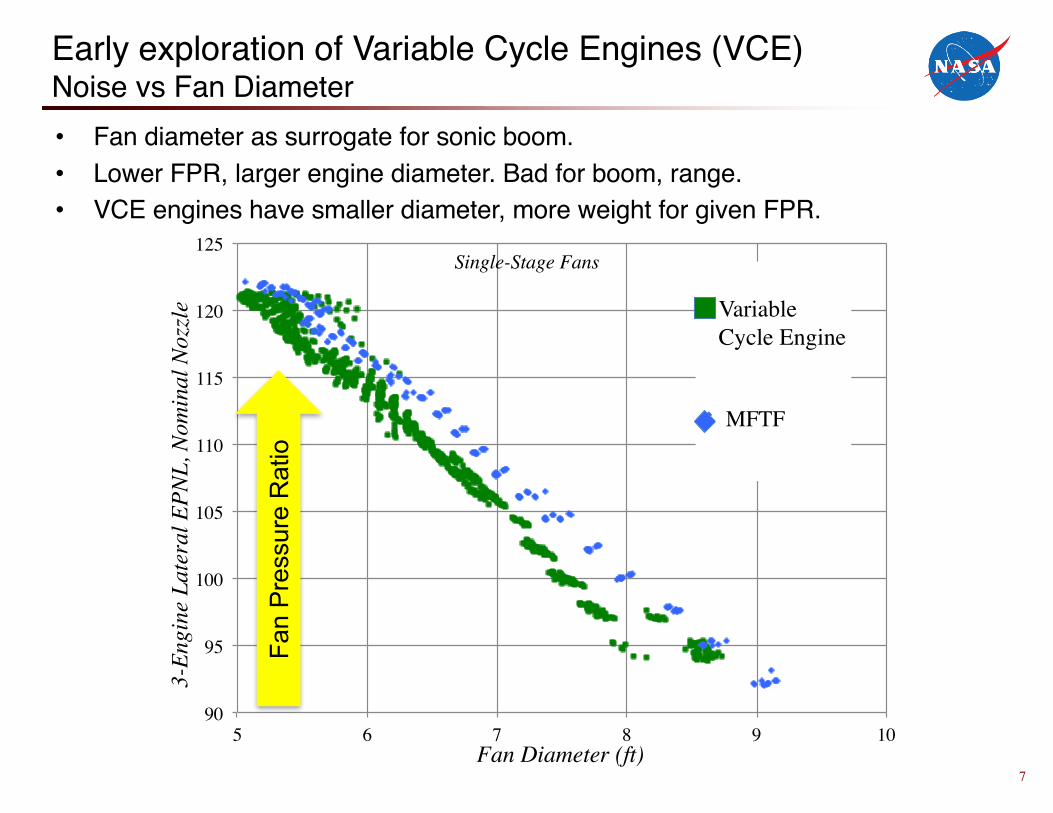
Early exploration of Variable Cycle Engines (VCE)Noise vs Fan Diameter• Fan diameter as surrogate for sonic boom.• Lower FPR, larger engine diameter. Bad for boom, range.• VCE engines have smaller diameter, more weight for given FPR.
90
95
100
105
110
115
120
125
5 6 7 8 9 10
3-En
gine
Lat
eral
EPN
L, N
omin
al N
ozzl
e
Fan Diameter (ft)
Variable Cycle Engine
Conventional
Fan
Pres
sure
Rat
io
MFTF
Single-Stage Fans

8
Early exploration of Variable Cycle Engines (VCE)Fan stage count
• Increasing FPR produces smaller engines, more range.• As FPR further increases, fan losses become prohibitive—add fan stages.• As fan stages increase past 2, engine weight increases and max range suffers.• Two-stage VCE significantly better range than two-stage MFTF.• At FPRs where jet noise is tolerable, the mixed flow turbofan gives comparable
or better range.
Fan
Pres
sure
Rat
io

9
Acoustic Impact of Nozzle typeTSS models for noise of three-stream nozzles
• Empirical noise models for various three-stream nozzles developed from model-scale aeroacoustic tests.
• Applied as ‘corrections’ to basic Stone jet noise model in NASA’s Aircraft Noise Prediction Program (ANOPP).
Internal Mix Conventional
3StreamExt
Split
1
3StreamExtOffset
Inverted
Three-stream nozzle types in TSS
Three-stream test rig
Correction to basic jet noise spectral directivity prediction

10
Iso16 Test: Nozzle Type Validation Results
• Noise prediction codes applied to VCE designs, tested on six nozzle types in isolation.
• Direct comparison of nozzles on same engine cycle.• Results compared at spectral directivity and EPNL levels.• Only separate flow nozzle significantly different.• Most cases predicted within expected uncertainty of ±1 EPNdB.
-4
-3
-2
-1
0
1
2
3
50 60 70 80 90 100 110
Pred
ict -
Dat
a (d
EPNd
B)
% thrust
EPNL Prediction Error
InternalMixConventionalExternMixInvertedSplitExternOffset
80
82
84
86
88
90
92
94
1.4 1.5 1.6 1.7
Sing
le, u
nins
talle
d je
t-com
pone
nt E
PNL
Nozzle Pressure Ratio
MFTFConventionalInvertedSplit3StreamExtOffset

11
JSI Tests: Effect of Installation on Jet Noise
• Early simple experiments documented effect of shielding/reflection for simple round jet, and the addition of a trailing edge dipole source.
• Simple models developed for installation effect, but did not include impact of multiple stream nozzles, limited planform size, or flight.
StDj
1/12
Oct
ave
PSD
(dB
)
10-2 10-1 100 101
ShieldReflectIsolated
633273986859
5 dB
Shielding Effect
Jet / SurfaceInteraction Noise
Reflected Noise

12
JSI1044 Test: Installation Impact
• Impact of installing engines underwing and overwing• Static (no flight stream) test• First jet-surface interaction test with multi-stream nozzles, realistic geometry
98
100
102
104
106
108
2.1 2.2 2.3 2.4 2.5
EPNL
Fan Pressure Ratio
Underwing
Isolated
Overwing
Static, xE/D~6, JSI1044 test
Jet E
PNL
2 dB
More shielding benefit possible from tailored nozzles—future tech development.

13
90
92
94
96
98
100
EPN
L, 3
-eng
ine,
jet c
ompo
nent
, 100
%
Range
Conventional
Inverted
Split
InternalMix
Ch4-10 goal
Selected
Engine/Nozzle Final Design for Validation
• VCE coupled with LM1044 aerodynamic model and new noise prediction codes to predict mission range and Lateral EPNL.
• Designs that maximize range while meeting noise goal selected for demonstration
• Also selected designs requiring Programmed Lapse Rate (PLR) to demonstrate design sensitivities.
Nozzle
100 nmiFPR=1.8
FPR=2.0
Internal Mix
Conventional
Split
Inverted

14
JSI16 Integrated Propulsion Test
• Ground test conducted on selected engine/nozzles to demonstrate that noise goal was met with integrated propulsion system.
• Test conducted at GRC Aero-Acoustic Propulsion Lab, an anechoic wind tunnel with engine simulator.
• Four nozzle types, seven engines, three installation variations, center top-mounted and outboard underwing installations assessed at multiple flight speeds.
Bridges, J. “Aeroacoustic Validation of Installed Low Noise Propulsion for NASA’s N+2 Supersonic Airliner”, AIAA SciTech 2018 Monday AM
15
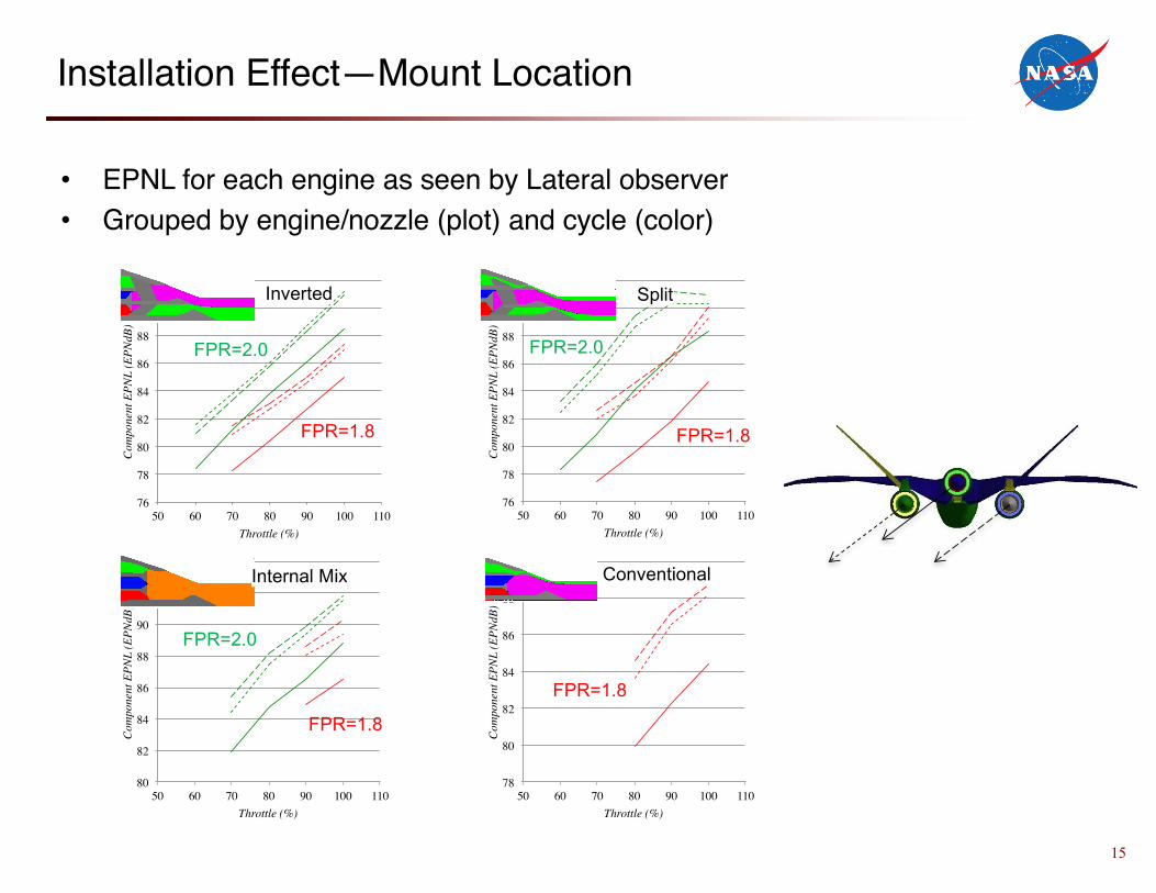
Installation Effect—Mount Location
• EPNL for each engine as seen by Lateral observer• Grouped by engine/nozzle (plot) and cycle (color)
76
78
80
82
84
86
88
90
92
50 60 70 80 90 100 110
Com
pone
nt E
PNL
(EPN
dB)
Throttle (%)
IVP44
S60R60R300S60R60R300
76
78
80
82
84
86
88
90
92
50 60 70 80 90 100 110
Com
pone
nt E
PNL
(EPN
dB)
Throttle (%)
IVS19
S60R60R300S60R60R300
80
82
84
86
88
90
92
94
50 60 70 80 90 100 110
Com
pone
nt E
PNL
(EPN
dB)
Throttle (%)
IM01
S60R60R300S60R60R300
78
80
82
84
86
88
90
50 60 70 80 90 100 110
Com
pone
nt E
PNL
(EPN
dB)
Throttle (%)
CVP01
S60R60R300
Split
Conventional
Inverted
Internal Mix
FPR=1.8
FPR=2.0
FPR=1.8
FPR=2.0
FPR=1.8
FPR=1.8
FPR=2.0

16
Comparisons of Design Predictions and Data
• JSI16 test Data plotted against design Predictions.• Predictions match Data within 1EPNdB, expected uncertainty of prediction
method.
90
92
94
96
98
100EP
NL,
3-e
ngin
e, je
t com
pone
nt, 1
00%
Range
PredictionDataCh4-10 goal
Data Prediction
Conventional
Inverted
Split
InternalMix
Ch4-10 goal
100 nmi
Significance: We have valid design tools for propulsion noise and know what must be done to meet airport noise regulations. This is not yet a closed design.

17
Summary
• NASA-supported research has helped develop significantly improved jet noise prediction methods.
• New tools allow strong insight into physics of jet noise generation, and design of exhaust systems for noise.
• NASA-supported research has explored many low-noise nozzle concepts brought forward by noise community.
• Acoustic performance of concepts shown to reliably reduce noise captured in system-level tools and used to validate physics-based methods.
• Installation effects on exhaust noise explored and modeled.• System-level propulsion studies used new noise tools to explore variable
cycle engine concepts and find best designs that meet LTO noise requirements for a low-boom, 70 pax, supersonic aircraft.
• Study results for noise validated in model-scale acoustic test.

18
• While formally the Low-Noise Propulsion Tech Challenge was successfully met, there were caveats.
– Although the fidelity of the range calculations were rough, the range of the acoustically successful designs were not satisfactory for commercial airliners.
– The original LM1044 aircraft did have a low boom signature, but the larger engines would have necessitated a redesign of the flow lines to regain low boom status.
• Significant lessons learned for future development of commercial supersonic aircraft
– Airport noise will be a problem even if the vehicle does not fly supersonic over land.– Smaller aircraft than the 70PAX, M 1.6 LM1044 would be closer to subsonic fleet.– VCEs not significantly better than mixed-flow turbofans given noise restrictions.– Alternate operating procedures during landing and takeoff could help noise immensely.– Installation effects are very significant and should be take advantage of.
• LTO noise will have to be a major design requirement for successful design– Adequate noise levels cannot be obtained by nozzle design or engine cycle alone.– Acoustic benefits from propulsion installation will be required.
But there’s more work to be done…
