nasa’s in space manufacturing initiatives
TRANSCRIPT

1
NASA’s In Space Manufacturing Initiatives:
Overview and Update
R.G. Clinton Jr., PhD
Associate Director
Science and Technology Office
NASA Marshall Space Flight Center
Manufacturing Problem
Prevention Program
November 7, 2017
Aerospace Corporation
https://ntrs.nasa.gov/search.jsp?R=20170011109 2017-12-08T01:18:05+00:00Z

Contributors
2
• Niki Werkheiser: NASA MSFC In Space Manufacturing,
Program Manager
• Dr. Tracie Prater: NASA MSFC In Space Manufacturing,
Materials Characterization Lead
• Dr. Frank Ledbetter: NASA MSFC In Space Manufacturing,
Subject Matter Expert
• Kristin Morgan: NASA MSFC Additive Manufacturing Lead
• Andrew Owens: NASA Tech Fellow, MIT PhD Candidate
• Mike Snyder: Made In Space, Chief Designer
Agenda
NASA’s In Space Manufacturing Initiative (ISM)
A. The Case for ISM: WHY
B. ISM Path to Exploration
C. In Space Robotic Manufacturing and Assembly
(IRMA)
D. Additive Construction
Summary
3
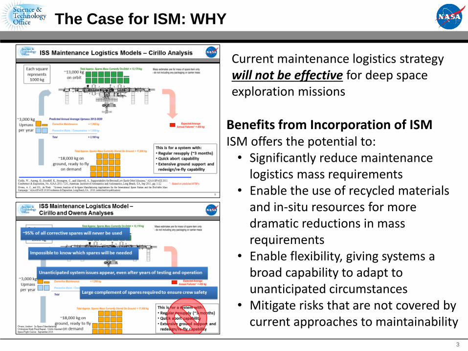
The Case for ISM: WHY
Current maintenance logistics strategy will not be effective for deep space exploration missions
Benefits from Incorporation of ISMISM offers the potential to:
• Significantly reduce maintenance logistics mass requirements
• Enable the use of recycled materials and in-situ resources for more dramatic reductions in mass requirements
• Enable flexibility, giving systems a broad capability to adapt to unanticipated circumstances
• Mitigate risks that are not covered by current approaches to maintainability
3
AES Mid-year Review March 2017
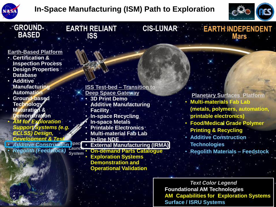
In-Space Manufacturing (ISM) Path to Exploration
EARTH RELIANTISS
CIS-LUNAR EARTH INDEPENDENTMars
Space
Launch
System
Text Color Legend
Foundational AM Technologies
AM Capabilities for Exploration Systems
Surface / ISRU Systems
GROUND-BASED
5
Earth-Based Platform• Certification &
Inspection Process• Design Properties
Database• Additive
Manufacturing Automation
• Ground-based Technology Maturation & Demonstration
• AM for Exploration Support Systems (e.g. ECLSS) Design, Development & Test
• Additive Construction• Regolith (Feedstock)
ISS Test-bed – Transition to Deep Space Gateway• 3D Print Demo• Additive Manufacturing
Facility• In-space Recycling• In-space Metals• Printable Electronics• Multi-material Fab Lab• In-line NDE • External Manufacturing (IRMA)• On-demand Parts Catalogue• Exploration Systems
Demonstration and Operational Validation
Planetary Surfaces Platform
• Multi-materials Fab Lab
(metals, polymers, automation,
printable electronics)
• Food/Medical Grade Polymer
Printing & Recycling
• Additive Construction
Technologies
• Regolith Materials – Feedstock
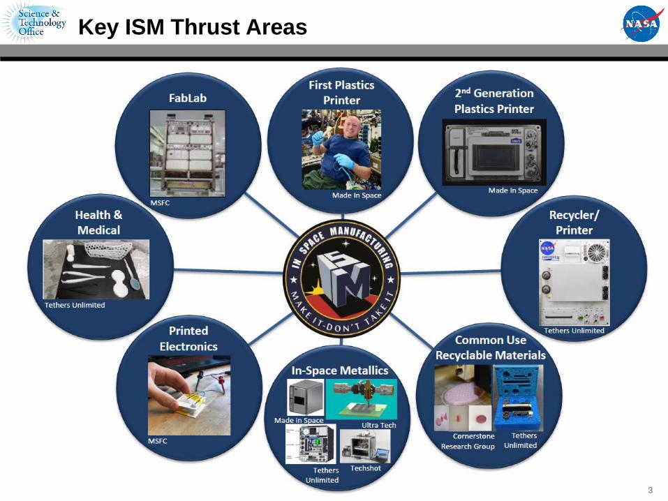
Key ISM Thrust Areas
3
AES Mid-Year Review April 20167
The First Step: The 3D Printing in Zero G Technology Demonstration Mission
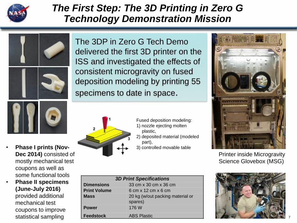
The 3DP in Zero G Tech Demo
delivered the first 3D printer on the
ISS and investigated the effects of
consistent microgravity on fused
deposition modeling by printing 55
specimens to date in space.
Fused deposition modeling:
1) nozzle ejecting molten
plastic,
2) deposited material (modeled
part),
3) controlled movable table
3D Print Specifications
Dimensions 33 cm x 30 cm x 36 cm
Print Volume 6 cm x 12 cm x 6 cm
Mass 20 kg (w/out packing material or
spares)
Power 176 W
Feedstock ABS Plastic
Printer inside Microgravity
Science Glovebox (MSG)
• Phase I prints (Nov-
Dec 2014) consisted of
mostly mechanical test
coupons as well as
some functional tools
• Phase II specimens
(June-July 2016)
provided additional
mechanical test
coupons to improve
statistical sampling

Material Properties• Tensile and Flexure: Flight specimens stronger and stiffer than ground counterparts
• Compression: Flight specimens are weaker than ground specimens
• Density: Flight specimens slightly more dense than ground specimens; compression
specimens show opposite trend
X-ray and CT Scans
• CT scans show more pronounced densification in lower half of flight specimens. [Not
statistically significant]
• No significant difference in number or size of voids between the flight and ground sets
Structured Light Scanning
• Protrusions along bottom edges
indicate that extruder tip may havebeen too close to the print tray (more pronounced for flight prints)
Microscopy
• Greater Densification of Bottom Layers (Flight tensile)
Process
• Z-calibration distance variation suspected to be primary factor
driving differences between flight and ground sample
• Potential influence of feedstock aging are being evaluated further
3DP Phase 1 Key Observations
12
Key Results: The 3D Printing in Zero G Technology
Demonstration Mission (Phase II)
9
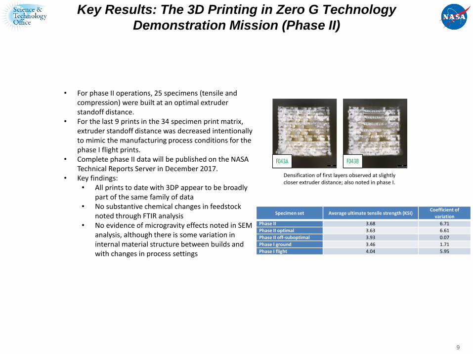
• For phase II operations, 25 specimens (tensile and compression) were built at an optimal extruder standoff distance.
• For the last 9 prints in the 34 specimen print matrix, extruder standoff distance was decreased intentionally to mimic the manufacturing process conditions for the phase I flight prints.
• Complete phase II data will be published on the NASA Technical Reports Server in December 2017.
• Key findings:• All prints to date with 3DP appear to be broadly
part of the same family of data • No substantive chemical changes in feedstock
noted through FTIR analysis• No evidence of microgravity effects noted in SEM
analysis, although there is some variation in internal material structure between builds and with changes in process settings
Densification of first layers observed at slightly closer extruder distance; also noted in phase I.
Specimen set Average ultimate tensile strength (KSI)Coefficient of
variation
Phase II 3.68 6.71
Phase II optimal 3.63 6.61
Phase II off-suboptimal 3.93 0.07
Phase I ground 3.46 1.71
Phase I flight 4.04 5.95

Key Results: The 3D Printing in Zero G Technology Demonstration Mission (Phase II): Additional Details
Mass and density data for phase I and phase II (considers all subsets of data) appear to be part of
the same data family
Analysis of PII tensile data and comparison with previous results suggests all data collected to date
is part of a single large, albeit variable, data setGround compression specimen performance is still somewhat distinct (higher) than other specimen sets, but these specimens were manufactured at the farthest extruder distance
Structured light scanning data shows phase II flight specimens manufactured at the optimal extruder
distance exhibit good agreement with the CAD model, although there is some slight build to build
variability in geometrySuboptimal compression specimens (manufactured at closer extruder standoff distance) show fiber distortion and distortion in the center of the specimen (defined as the x-y plane about halfway up the specimen) for phase II specimensInterestingly, warpage and protrusions observed for phase I tensile specimens are not present in phase II flight tensile prints, even those manufactured at the suboptimal extruder setting
Microscopy Compression specimens manufactured at the suboptimal condition contain surface defects along the sides that appear to be printing defects where the fiber is distorted. The cross-section showed voids in the center of the sample, likely due to separation between the fiber layers such that the sample was not completely dense. Specimens manufactured at this condition are mechanically weaker than specimens manufactured at greater standoff distances.Microscopy results for tensile specimens at closer extruder distance shows characteristic densification of first layers noted in phase I flight specimens and subsequent ground-based study
FTIR showed some small chemical changes between phase I and phase II flight feedstock (phase II
feedstock was nearly two years older than phase I feedstock at time of printing). However, spectra
still show a very high degree of similarity and are considered in family with one another.
X-ray/CT analysis results still pending.
Overall we cannot attribute any of the observations to microgravity effects. Variations in phase I
data appear to be traceable to printer variability, differences in manufacturing process settings
(extruder standoff distance), and data scatter characteristic of many additively manufactured
materials and processes.
AES Mid-Year Review April 201611
ISM Utilization and the Additive Manufacturing Facility (AMF): Functional Parts
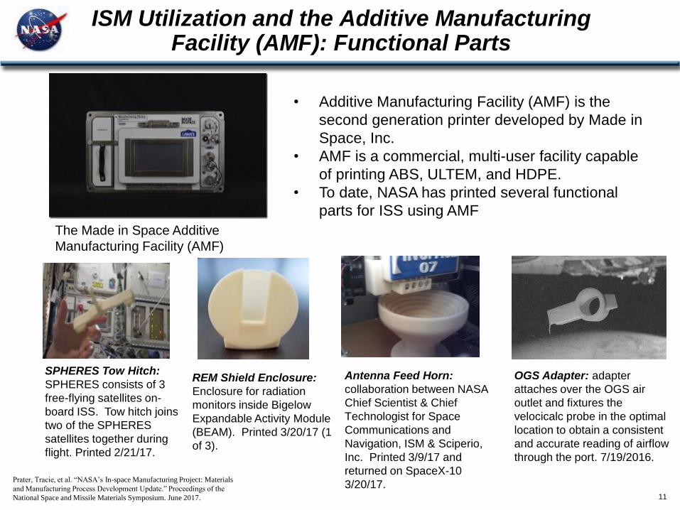
• Additive Manufacturing Facility (AMF) is the
second generation printer developed by Made in
Space, Inc.
• AMF is a commercial, multi-user facility capable
of printing ABS, ULTEM, and HDPE.
• To date, NASA has printed several functional
parts for ISS using AMF
The Made in Space Additive
Manufacturing Facility (AMF)
SPHERES Tow Hitch:
SPHERES consists of 3
free-flying satellites on-
board ISS. Tow hitch joins
two of the SPHERES
satellites together during
flight. Printed 2/21/17.
REM Shield Enclosure:
Enclosure for radiation
monitors inside Bigelow
Expandable Activity Module
(BEAM). Printed 3/20/17 (1
of 3).
Antenna Feed Horn:
collaboration between NASA
Chief Scientist & Chief
Technologist for Space
Communications and
Navigation, ISM & Sciperio,
Inc. Printed 3/9/17 and
returned on SpaceX-10
3/20/17.
OGS Adapter: adapter
attaches over the OGS air
outlet and fixtures the
velocicalc probe in the optimal
location to obtain a consistent
and accurate reading of airflow
through the port. 7/19/2016.
Prater, Tracie, et al. “NASA’s In-space Manufacturing Project: Materials
and Manufacturing Process Development Update.” Proceedings of the
National Space and Missile Materials Symposium. June 2017.

AES Mid-Year Review April 201612
ReFabricator from Tethers Unlimited, Inc.: Closing the Manufacturing Loop
• Technology Demonstration Mission payload
conducted under a phase III SBIR with Tethers
Unlimited, Inc.
• Refabricator demonstrates feasibility of plastic
recycling in a microgravity environment for long
duration missions
• Closure of the manufacturing loop for FDM has
implications for reclamation of waste material
into useful feedstock both in-space an on-earth
• Refabricator is an integrated 3D printer (FDM) and
recycler
• Recycles 3D printed plastic (ULTEM 9085) into
filament feedstock through the Positrusion
process
• Environmental testing of engineering test unit
completed at MSFC in April
• Payload CDR completed in mid-June
• Operational on ISS in 2018
Refabricator ETU
Prater, Tracie, et al. “NASA’s In-space Manufacturing Project: Materials
and Manufacturing Process Development Update.” Proceedings of the
National Space and Missile Materials Symposium. June 2017.

AES Mid-Year Review April 201613
Common Use Materials Development: Recyclable Materials
• Logistics analyses show the dramatic impact of a recycling
capability for reducing initial launch mass requirements for long
duration missions
• Current packaging materials for ISS represent a broad
spectrum of polymers: LDPE, HDPE, PET, Nylon, PVC
• Tethers CRISSP (Customizable Recyclable ISS Packaging) seeks
to develop common use materials (which are designed to be
recycled and repurposed) for launch packaging
• Work under phase II SBIR
• Recyclable foam packaging made from thermoplastic
materials using FDM
• Can create custom infill profiles for the foam to yield specific
vibration characteristics or mechanical properties
• Cornerstone Research Group (CRG) is working under a phase II
SBIR on development of reversible copolymer materials
• Reversible copolymer acts as a thermally activated viscosity
modifier impacting the melt properties of the material
• Designs have strength and modulus values comparable to or
exceeding base thermoplastic materials while maintaining
depressed viscosity that makes them compatible with FDM
CRISSP (image from
Tethers Unlimited)
FDM prints using
reclaimed anti-static
bagging film with
reversible cross-linking
additive (image from
Cornerstone Research
Group)

AES Mid-Year Review April 201614
Toward an In-Space Metal Manufacturing Capability
• Made in Space Vulcan unit (Phase I SBIR)
• Integrates FDM head derived from AMF,
wire and arc metal deposition system, and
a CNC end-mill for part finishing
• Ultra Tech Ultrasonic Additive Manufacturing
(UAM) system (Phase I SBIR)
• Prints parts using sound waves to
consolidate layers of metal from foil
feedstock
• Tethers Unlimited MAMBA (Metal Advanced
Manufacturing Bot-Assisted Assembly) (Phase
I SBIR)
• Builds on ReFabricator recycling process
• Bulk feedstock is CNC-milled
• Techshot, Inc. SIMPLE (Sintered Inductive
Metal Printer with Laser Exposure) (Phase II
SBIR)
• AM process with metal wire feedstock,
inductive heating, and a low-powered
laser
Illustration of UAM process
(image courtesy of Ultra Tech)
Illustration of Vulcan
Exterior Unit (image
courtesy of Made in Space)
Tethers Unlimited MAMBA
concept. Image courtesy of
Tethers Unlimited.
Techshot’s SIMPLE, a small
metal printer developed under a
Phase I SBIR. Image courtesy
of Techshot.
AES Mid-Year Review April 201615
Ground-based Work on Printed Electronics
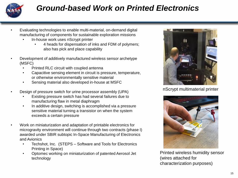
• Evaluating technologies to enable multi-material, on-demand digital
manufacturing of components for sustainable exploration missions
• In-house work uses nScrypt printer
• 4 heads for dispensation of inks and FDM of polymers;
also has pick and place capability
• Development of additively manufactured wireless sensor archetype
(MSFC)
• Printed RLC circuit with coupled antenna
• Capacitive sensing element in circuit is pressure, temperature,
or otherwise environmentally sensitive material
• Sensing material also developed in-house at MSFC
• Design of pressure switch for urine processor assembly (UPA)
• Existing pressure switch has had several failures due to
manufacturing flaw in metal diaphragm
• In additive design, switching is accomplished via a pressure
sensitive material turning a transistor on when the system
exceeds a certain pressure
• Work on miniaturization and adaptation of printable electronics for
microgravity environment will continue through two contracts (phase I)
awarded under SBIR subtopic In-Space Manufacturing of Electronics
and Avionics
• Techshot, Inc. (STEPS – Software and Tools for Electronics
Printing in Space)
• Optomec working on miniaturization of patented Aerosol Jet
technology
Printed wireless humidity sensor
(wires attached for
characterization purposes)
nScrypt multimaterial printer

AES Mid-Year Review April 201616
The Multimaterial Fabrication Laboratory for ISS (“FabLab”)
• NASA is evaluating proposals to provide a feasible design and demonstration of a first-
generation multimaterial, multiprocess In-space Manufacturing Fabrication Laboratory
for demonstration on the ISS
• Minimum target capabilities include:
• Manufacturing of metallic components
• Meet ISS EXPRESS Rack constraints for power and volume
• Limit crew time
• Incorporate remote and autonomous verification and validation of parts
Power consumption for
entire rack is limited to 2000
W
Payload mass limit for rack
is less than 576 lbm
Typical EXPRESS
Rack structure
Threshold
The system should have the ability for on-
demand manufacturing of multi-material
components including metallics and polymers
as a minimum.
The minimum build envelope shall be 6” x 6” x
6”.
The system should include the capability for
earth-based remote commanding for all nominal
tasks.
The system should incorporate remote, ground-
based commanding for part handling and
removal in order to greatly reduce dependence
on astronaut time.*
The system should incorporate in-line
monitoring of quality control and post-build
dimensional verification.
• Phased approach
• Phase A – scaleable ground-based prototype
• Phase B – mature technologies to pre-flight deliverable
• Phase C – flight demonstration to ISS

AES Mid-year Review March 2017
Archinaut Dragonfly CIRAS
A Versatile In-Space Precision Manufacturing and Assembly System
On-Orbit Robotic Installation and Reconfiguration of Large Solid Radio Frequency (RF) Reflectors
A Commercial Infrastructure for Robotic Assembly and Services
Tipping Point Objective
A ground demonstration of additive manufacturing of extended structures and assembly of those structures in a relevant space environment.
A ground demonstration of robotic assembly interfaces and additive manufacture of antenna support structures meeting EHF performance requirements.
A ground demonstration of reversible and repeatable robotic joining methods for mechanical and electrical connections feasible for multiple space assembly geometries.
Team
Made In Space, Northrop Grumman Corp., Oceaneering Space Systems, Ames Research Center
Space Systems/Loral, Langley Research Center, Ames Research Center, Tethers Unlimited, MDA US & Brampton
Orbital ATK, Glenn Research Center, Langley Research Center, Naval Research Laboratory
Concept by Made In Space
In-space Robotic Manufacturing
and Assembly (IRMA) Overview
Concept by Space
Systems/LoralConcept by Orbital ATK

18
Shared Vision: Capability to print custom-designed
expeditionary structures on-demand, in the field,
using locally available materials.
X: 65
ft.
Y: 25
ft.
Z: 18
ft.B-hut
(guard shack)
16’ x 32’ x 10’
Additive
Construction with
Mobile Emplacement
(ACME)
NASA
Automated Construction of
Expeditionary Structures
(ACES)
Construction Engineering
Research Laboratory - Engineer
Research and Development
Center
(CERL – ERDC)
Additive Construction Dual Use Technology Projects
For Planetary and Terrestrial Applications
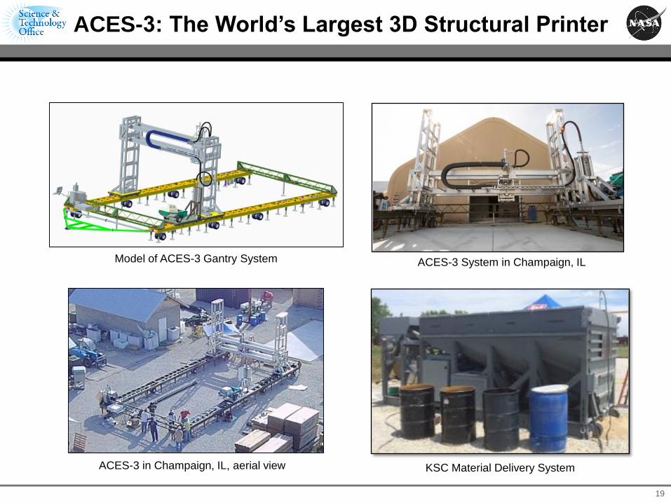
19
ACES-3 System in Champaign, IL
ACES-3 in Champaign, IL, aerial view KSC Material Delivery System
Model of ACES-3 Gantry System
ACES-3: The World’s Largest 3D Structural Printer

Summary
• Current maintenance logistics strategy will not be effective for deep space exploration missions
• ISM offers the potential to: o Significantly reduce maintenance logistics mass requirementso Enable the use of recycled materials and in-situ resources for more dramatic
reductions in mass requirementso Enable flexibility, giving systems a broad capability to adapt to unanticipated
circumstanceso Mitigate risks that are not covered by current approaches to maintainability
• Multiple projects are underway currently to develop and validate these capabilities for infusion into ISM exploration systems
• ISS is a critical testbed for driving out these capabilities
• Developing and testing FabLab is a major milestone for springboard to DSG/Cis-lunar Space applications
• ISM is a necessary paradigm shift in space operations – design for repair culture must be embraced
• ISM team needs to be working with exploration system designers now to identify high-value application areas and influence design