nasa’s advanced composites-based solar sail system for .... juan m... · 17/01/2017 · system...
TRANSCRIPT

NASA’s Advanced Composites-based Solar Sail
System for Interplanetary Small Satellite Missions
Juan (Johnny) Fernandez, Geoffrey Rose, Casey Younger,
Greg Dean, Olive Stohlman, Jay Warren, W. Keats Wilkie
NASA Langley Research Center
January 17, 2017

Outline
MOTIVATION
Mini-CTM COMPOSITE BOOMS
SOLAR SAIL DEPLOYMENT MECHANISMS
FUNCTIONAL TESTING
ENVIRONMENTAL TESTING
- Launch Vibration Testing
- Thermal Vacuum Testing
CONCLUDING REMARKS
2

Outline
MOTIVATION
Mini-CTM COMPOSITE BOOMS
SOLAR SAIL DEPLOYMENT MECHANISMS
FUNCTIONAL TESTING
ENVIRONMENTAL TESTING
- Launch Vibration Testing
- Thermal Vacuum Testing
CONCLUDING REMARKS
3

Motivation & Objective
• U.S. low-cost Cubesat-based solar sail technology demonstrator missions have relied on AFRL’s rollable metallic TRAC booms.
– NanoSail-D2 (2010), LightSail 1 (2015) & 2 (2017), and NASA’s NEA Scout (2018).
– Deployment anomalies seem to have occurred on these flight demonstrators that could be attributed to the boom or boom deployer system.
• Elgiloy alloy TRAC booms used in NEA Scout sail structure have beensomewhat problematic with stiffness, thermal distortion, deployedprecision, mass, and manufacturing.
– NEA Scout had to switch from its initial optimal four-quadrant configuration to a single-squaresail design supported only at its four vertices, in order to shade the high CTE booms.
– At the time there was no composite alternative capable of complying with NEAS volume req.
• In February 2016, LaRC was asked by NASA HQ/AES to develop a planto accelerate development of a LaRC composite boom as a potentialrisk reduction alternative to the current NEAS baseline TRAC boom sys.
• Objective: Effectively needed to advance the composite sail system TRL from3 5, including boom & deployer technology, by the NEAS project CDR inAugust 2016.
4
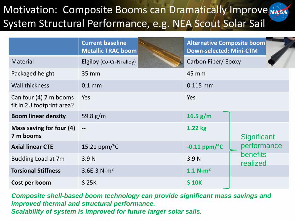
Motivation: Composite Booms can Dramatically Improve System Structural Performance, e.g. NEA Scout Solar Sail
Current baselineMetallic TRAC boom
Alternative Composite boomDown-selected: Mini-CTM
Material Elgiloy (Co-Cr-Ni alloy) Carbon Fiber/ Epoxy
Packaged height 35 mm 45 mm
Wall thickness 0.1 mm 0.115 mm
Can four (4) 7 m booms fit in 2U footprint area?
Yes Yes
Boom linear density 59.8 g/m 16.5 g/m
Mass saving for four (4) 7 m booms
-- 1.22 kg
Axial linear CTE 15.21 ppm/°C -0.11 ppm/°C
Buckling Load at 7m 3.9 N 3.9 N
Torsional Stiffness 3.6E-3 N-m2 1.1 N-m2
Cost per boom $ 25K $ 10K
Composite shell-based boom technology can provide significant mass savings and
improved thermal and structural performance.
Scalability of system is improved for future larger solar sails.
Significant
performance
benefits
realized
Outline
MOTIVATION
Mini-CTM COMPOSITE BOOMS
SOLAR SAIL DEPLOYMENT MECHANISMS
FUNCTIONAL TESTING
ENVIRONMENTAL TESTING
- Launch Vibration Testing
- Thermal Vacuum Testing
CONCLUDING REMARKS
6

LaRC Composite Boom Concepts and Downselect
• LaRC Solar Sail Structures Team has three thin-shell, deployable composite boom concepts under development:– Mini-CTM (Collapsible Tubular Mast)
– SHEARLESS Boom *U.S. Patent pending
– Ultra-Thin TRAC Boom
• Mini-CTM boom was selected as best option for accelerated development:– Closed-section geometry yields best
structural performance (compression, bending & torsion) for 6U-class volume constraints.
– Highest uniformity and deployed precision.
– Most developed of three current concepts. Minimum development time to NEA Scout readiness.
– No significant difference in development costs relative to other concepts.
7
Mini-
CTM/Omega
concept Stif
fnes
s
Pack
agea
bili
ty
Ease
of
man
ufa
ctu
re
Pre
dic
tab
ility
;re
liab
ility
SHEARLESS 2 2 1 2
C-TRAC 3 3 2 3
Mini-CTM/W 1 1 3 1
Their flattened height: 45 mm. Thickness: 0.3 - 0.5 mm. Mass: 16 - 32 g/m
Demonstrated that 14 m booms fit in a 10 cm x 10 cm x 5 cm (0.5 U) vol.

Full-scale, high-precision, 7 m Mini-CTM booms
8
7 m booms fabricated in-house using composite
materials and adhesives with space heritage.
New fabrication process that cures the two boom
halves and bonds them in a single step using a
single bottom mold and an inner silicone plug.
Achieved negligible boom straightness errors (sub-
centimeter), and boom-to-boom variability with new
low-CTE carbon foam mold.
Booms may be safely wrapped around 45 mm OD
spool without delamination or fracture = vol. req.
No appreciable creep induced boom axial
curvature (bow) after several months of storage.
Boom cross-section flattening of up to 30% due to
high strains in stowed configuration (not expected
to increase more over time - plateaued).
7.2 m
Small axial curvature of
EDU Booms
< 5”
Boom self-supported under 1g for ease of testing
Boom keeps desired cross-section
after curing, but flattens after
prolonged stowage = 50% drop in Pcr
Boom coils around 45
mm spool without
delamination or fracture
Near zero
in-plane
curvature
7-m boom
post-cured
Carbon foam mold
23 mm
16 mm
(-30%)

Outline
MOTIVATION
Mini-CTM COMPOSITE BOOMS
SOLAR SAIL DEPLOYMENT MECHANISMS
FUNCTIONAL TESTING
ENVIRONMENTAL TESTING
- Launch Vibration Testing
- Thermal Vacuum Testing
CONCLUDING REMARKS
9

Composite Boom Deployer Design
• Drop-in replacement for baseline NEA Scout metallic TRAC
boom deployer. (Requirements derived using MSFC design
and interfaces).
– Fits within existing volume and footprint allocations.
• Boom deployer may be used with a single square sail
(NEAS) or with a 4-quadrant sail (simply manuf. & packag.)
• Pin pusher/puller locks boom spools & motor gears before
(launch) and after (operations) deployment.
• “Puller” design adopted over traditional “pusher” one.
– Twin-boom spool design, which is motor co-driven by a
central metal SS strip spool.
– Co-driven steel strips provide rotational moment to the
boom spools. Strips are under tension by clock springs.
– Minimizes risks of boom blooming, boom root buckling and
potential jamming during deployment.
10
Boom deployer U.S. patent pending
Spring-loaded sliding nut plates aid in full
boom cross-section recovery at the end of
deployment serving as the boom root
fixation points.
Complete solar sail system
Sail spool for
single square
sail (wrapped)
Two booms get co-wrapped with
a thin SS strip per boom spool.
SS strip spool
Motor

Composite Solar Sail System Mass Breakdown
11
• Composite Booms and Deployer mass estimate*:
– Deployer: 970 g
– Booms (4 total): 452 g
• 113 g each (~16.5 g/m)
– Launch locks: 35 g
– Total: 1.45 kg
– Metallic TRAC booms alone are ~1.6 kg
• Complete composites-based solar sail system (CS3): 2.4 kg (incl. deployer electronics)
– Mass reduction of 1.2 kg (10% s/c mass) vs baseline NEA Scout design
* Booms and deployer system only. Does not include
deployer electronics
Complete Solar Sail System
Mass of boom & deployer + Sail post (-80 g)
Mass of boom & deployer + Sail & spool

Outline
MOTIVATION
Mini-CTM COMPOSITE BOOMS
SOLAR SAIL DEPLOYMENT MECHANISMS
FUNCTIONAL TESTING
ENVIRONMENTAL TESTING
- Launch Vibration Testing
- Thermal Vacuum Testing
CONCLUDING REMARKS
12
Full-Scale Deployment Tests
13
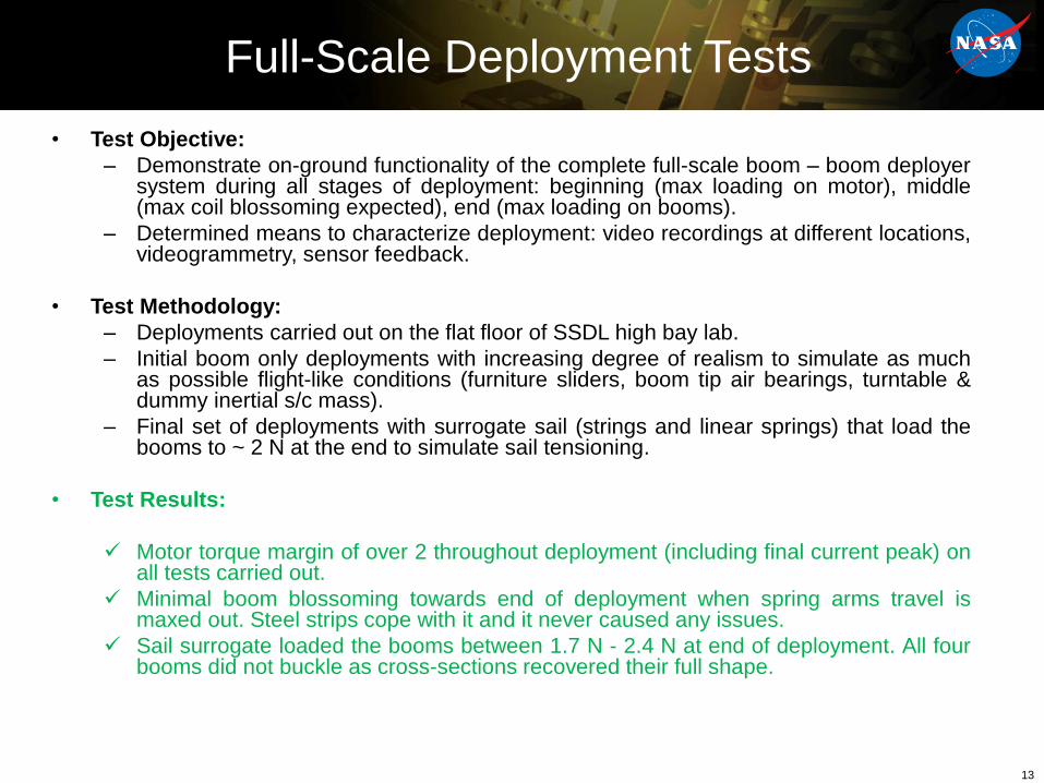
• Test Objective:
– Demonstrate on-ground functionality of the complete full-scale boom – boom deployersystem during all stages of deployment: beginning (max loading on motor), middle(max coil blossoming expected), end (max loading on booms).
– Determined means to characterize deployment: video recordings at different locations,videogrammetry, sensor feedback.
• Test Methodology:
– Deployments carried out on the flat floor of SSDL high bay lab.
– Initial boom only deployments with increasing degree of realism to simulate as muchas possible flight-like conditions (furniture sliders, boom tip air bearings, turntable &dummy inertial s/c mass).
– Final set of deployments with surrogate sail (strings and linear springs) that load thebooms to ~ 2 N at the end to simulate sail tensioning.
• Test Results:
Motor torque margin of over 2 throughout deployment (including final current peak) onall tests carried out.
Minimal boom blossoming towards end of deployment when spring arms travel ismaxed out. Steel strips cope with it and it never caused any issues.
Sail surrogate loaded the booms between 1.7 N - 2.4 N at end of deployment. All fourbooms did not buckle as cross-sections recovered their full shape.

Deployment Test GSE
• Boom tips supported by 4 standalone free-floating air bearing cradles.
• No hoses to interfere with boom deploys and add parasitic mass/inertial reactions.
• Up to 20 minutes of continuous operation with single air bottle charge.
– Deployment to proceed slowly (18 min) to minimize inertial reactions into booms.
• Central turntable permits rotation of deployer as booms unwrap.
– Deployer translation constrained.
• 8.5 kg dummy mass added to simulate s/c rotational inertia.
• Prototype electronic system (Arduino) includes all the functionality of
future flight system – i.e. Motor heater, motor controller, temperature and
IR sensor suite, launch lock.14
Assembled off-loader.
2-axis
decoupling
connector
to boom tip
Air bearing cradle configuration at start of deployment.
Videogrammetry IR
& bowtie markers
EDU Electronic system
Turntables/c inertia simulator

Full-Scale Deployment Test #8
15

Outline
MOTIVATION
Mini-CTM COMPOSITE BOOMS
SOLAR SAIL DEPLOYMENT MECHANISMS
FUNCTIONAL TESTING
ENVIRONMENTAL TESTING
- Launch Vibration Testing
- Thermal Vacuum Testing
CONCLUDING REMARKS
16

Launch Random Vibration Testing - Results
17
• The stowed sail system was vibed in all 3 axis following the preliminary derived MPE from SLS.
• The system showed no signs of visible damage during the developmental vibration testing.– Pre and post-vibe sine sweeps showed small differences at mid/high frequencies due to loosening of fixture mounting screws (not part
of the sail system)
✓ Post-vibe full deployment test with surrogate sail was nominal.
X
Y
Z
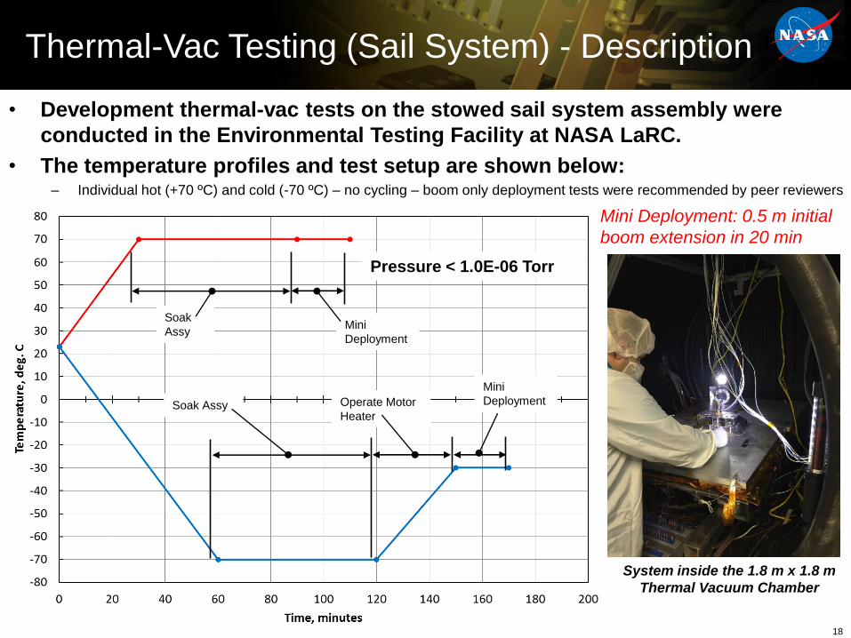
Thermal-Vac Testing (Sail System) - Description
18
• Development thermal-vac tests on the stowed sail system assembly were
conducted in the Environmental Testing Facility at NASA LaRC.
• The temperature profiles and test setup are shown below:– Individual hot (+70 ºC) and cold (-70 ºC) – no cycling – boom only deployment tests were recommended by peer reviewers
Operate Motor
Heater
Soak
AssyMini
Deployment
Soak Assy
Mini
Deployment
Pressure < 1.0E-06 Torr
System inside the 1.8 m x 1.8 m
Thermal Vacuum Chamber
Mini Deployment: 0.5 m initial
boom extension in 20 min

Thermal-Vac Testing at -70 ºC – Results
19
Motor speed of 775 rpm was used to simulate the ~20 min operating time of the full depl.
Motor was successfully operated in vacuum for 17 min at -30 ºC after soaking at -70 ºC for 1 hour. Current readings were acceptable for a Motor Torque SF = 2.
• Motor heater, that was used to hold motor temp at -30 ºC ± 3 ºC, functioned nominally.
Deployment was stopped prior to the 20 minute mark since one boom got caught on a thermocouple wire.
• 17 min deployment time, which is the actual run time of the ambient deployment tests
✓ Post-TVAC, ambient full deployment continuation test was nominal.
-40
-30
-20
-10
0
0
0.1
0.2
0.3
0.4
0.5
0.6
0.7
0 200 400 600 800 1000 1200
Mo
tor
Tem
per
atu
re (
°C)
Mo
tor
Cu
rren
t (A
)
Time (s)
Motor Performance in TVAC (-70°C)
Current Temperature x64 Normal Speed
Partially deployed boom
inside TVAC chamber

Outline
MOTIVATION
Mini-CTM COMPOSITE BOOMS
SOLAR SAIL DEPLOYMENT MECHANISMS
FUNCTIONAL TESTING
ENVIRONMENTAL TESTING
- Launch Vibration Testing
- Thermal Vacuum Testing
CONCLUDING REMARKS
20

Concluding Remarks
• A summary of the design and development of NASA’s next generation ACS3 for future small satellite science and exploration missions was presented.
– Functional testing of the full-scale system was challenging due to its gossamer nature and the use of a non-perfect “flat floor”.
– The key features that could form the basis of a future flight design were demonstrated to comply with typical mission requirements of a 6U cubesat-based solar sail.
– Engineering Development Unit (EDU) System passed all functional and environmental tests (launch vibration and functional under TVAC) of the AES funded program that are in line with NASA’s NEA Scout flight mission.
• ACS3 is 10% lighter than equivalent state-of-the-art (SoA) boom-supported solar sail systems, which translates to:
– Up to 10% higher characteristic accelerations for a faster solar sail design, which in return permits more margin in mission design and launch date (critical for low-cost piggy-back missions).
– More agile with less s/c rotational inertias sailcrafts, (e.g. 57% less than SoA) for faster science maneuvering, faster comms pointing/repointing, or increased RCS propellant margin.
• ACS3 is thermally stable under the considered mission operating requirements, avoiding:
– Thermally-induced risks during deployment and operations
– Need to shade the booms with the sail, enabling preferred four-quadrant sail designs and other s/c config.
• The use of high-performance composite CTM booms enables:
– Sail designs with an equal or higher structural margin than SoA designs for the same sail size (85 m2).
– Efficient scalable square solar sail designs up to 1000-1500 m2 (33-40 m on the side), with booms of 23-28 m in length, which is in line with the ESA/DLR GOSSAMER solar sail technology demonstrator missions roadmap.
• Current LaRC GCD project is targeting 14 m class CTM booms for a possible 12U CS-based solar sail (ACS3).
– Larger 360 m2 class (20 m on the side) solar sail of about 6 kg in mass, and 9U volume (2U x 2U x 2.25U).
– ~ 0.15 mm/s2 charact. acceleration for a total 18 kg mass s/c. Possible with SoA upscaled CubeSat components.
– Currently studying possible demonstrator missions (deep space targets) for such sailcraft.
21


BACK UP
23

Full-Scale Boom Deployment Test #4(x64 Normal Speed)
24
(click to view video)

3D Motion Capture System
• Vicon 3D videogrammetry system
successfully used to capture boom
deployment data:
– Boom tip displacement, speed
and acceleration.
– Deployer rotation, angular
velocity and acceleration.
• 8 cameras viewing complete
system. 4 cameras following each
boom tip.
25
Test # 4 – Furniture sliders, turntable, dummy mass.
Boom deployer rotation about the vertical Z axis
Test # 3 – Air bearings, no floor tracks, hand guided.
Boom tip Motion for Boom 1 (+Y) and Boom (-X).

Deployer Motor Performance
• Graph below shows motor feedback parameters during Test 5 as an example.
• For all deployment tests the torque margin was always >2 as max current seen is ~0.5 A and max allowed
is 1 A
• Motor current reduces over time as friction reduces from 0.3 A – 0.4 A to under 0.25 A. Spike at end of
deployment due to sail tensioning springs (0.4 A – 0.5 A).
• Motor speed profile: Initial 10% at 3000 rpm, 80% at 7500 rpm, 10% at 3000 rpm so as to not overload
motor at critical stages.
• ~18.5 min deployment time bounded by reduction of inertial effects and dynamics (slow) and by the run
time of the air bearings (fast).
• Motor counts for the 6.85 m booms is 94294, which is ~255 turns of the tape spool or ~ 30.5 of the boom
spools.
26

Thermal-Vac Testing +70 ºC - Results
27
Motor speed of 825 rpm was used to simulate ~20 min operating time for full deployment.
The deployer motor showed no signs of damage during thermal-vac testing.
Motor was successfully operated in vacuum for 20 min at +70 ºC after soaking at temp. for 1 h.
Current readings were nominal.
71
71.5
72
72.5
73
73.5
74
74.5
75
75.5
0
0.05
0.1
0.15
0.2
0.25
0 200 400 600 800 1000 1200
Mo
tor
Tem
per
atu
re (
°C)
Mo
tor
Cu
rren
t (A
)
Time (s)
Motor Performance in TVAC (+70°C)
Current Temperature x64 Normal Speed

COMPOSITE SAIL SYSTEM
STRUCTURAL MODELING
AND ANALYSIS
28

Analysis flowchart (for metallic TRAC
baseline)
Integrated model
• Detailed model of
booms
• One-element model
of membrane
• Structural analysis
with thermal
deformations
Membrane model
• Detailed (~5
cm) model of
membrane
• No model of
booms
Corner
displacements
Sail shape mesh
Thermal model
• Radiative and
conductive heat
transfer
Thrust model
Attitude control
model
Dynamic model
• Fixed-bus model
• Stiffness matrix includes the
effects of sail tensioning and
thermal loading
• Reduced dynamic model is
integrated with the spacecraft bus
for attitude control studies
Reduced/simplified
dynamic model
Shape
solution
Reduced/simplified Dynamic Model
Fixed-Bus Sail System Bending Mode

Thrust model
Membrane model
• Detailed (~5
cm) model of
membrane
• No model of
booms
Corner
displacements
Thermal model
• Radiative and
conductive heat
transfer
Attitude control
model
Dynamic model
• Fixed-bus model
• Stiffness matrix includes the
effects of sail tensioning and
thermal loading
• Reduced dynamic model is
integrated with the spacecraft bus
for attitude control studies
Reduced/simplified
dynamic model
Reduced/simplified Dynamic Model
Fixed-Bus Sail System Bending Mode
Ready
Analysis flowchart (for composite
booms)
Integrated model
• Detailed model of
booms
• One-element model
of membrane
• Structural analysis
with thermal
deformations
Sail shape mesh
Shape
solution

Integrated model
31
View A
View BView C
Root condition detailed on following slide Simple spring (identical to baseline) connects
boom to membrane
Bottom edge slides on the line
of the rigid body offset tip
fitting, imitating as-designed
slot
Rigid body
enforces tip fitting
offset

Integrated model: Root
32
Metallic TRAC Composite omega
Connectors in slots free to move in Z
Contact condition
against spool
Bolted holes fixed in two dimensions
Contact condition
with clamp and spool
Contact condition with rollers (both
models)
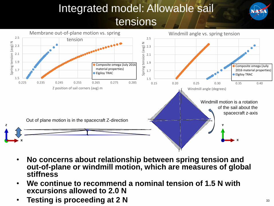
• No concerns about relationship between spring tension and out-of-plane or windmill motion, which are measures of global stiffness
• We continue to recommend a nominal tension of 1.5 N with excursions allowed to 2.0 N
• Testing is proceeding at 2 N
Integrated model: Allowable sail
tensions
33
Out of plane motion is in the spacecraft Z-direction
Windmill motion is a rotation
of the sail about the
spacecraft z-axis
1.5
1.7
1.9
2.1
2.3
2.5
0.225 0.235 0.245 0.255 0.265 0.275 0.285
Spri
ng
ten
sio
n (
avg)
N
Z position of sail corners (avg) m
Membrane out-of-plane motion vs. spring tension
Composite omega (July 2016material properties)Elgiloy TRAC
1.5
1.7
1.9
2.1
2.3
2.5
0.15 0.20 0.25 0.30 0.35 0.40
Spri
ng
ten
sio
n (
avg)
N
Windmill angle (degrees)
Windmill angle vs. spring tension
Composite omega (Juily2016 material properties)Elgiloy TRAC
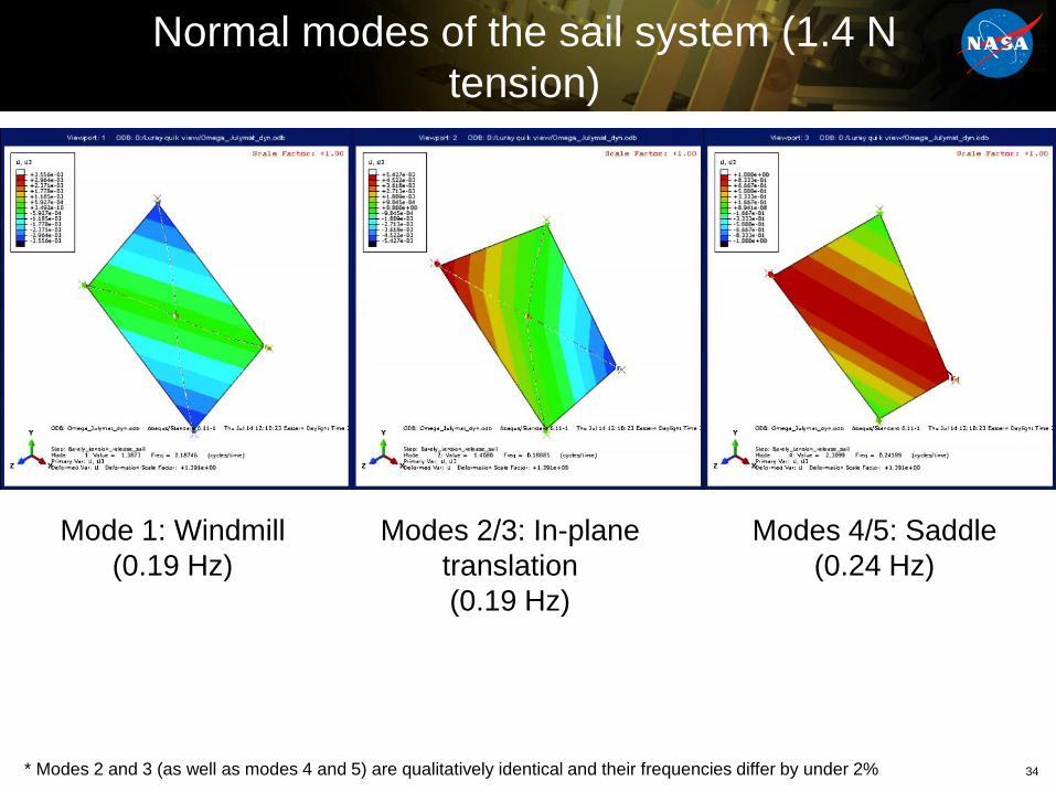
Normal modes of the sail system (1.4 N
tension)
34
Mode 1: Windmill
(0.19 Hz)
Modes 2/3: In-plane
translation
(0.19 Hz)
Modes 4/5: Saddle
(0.24 Hz)
* Modes 2 and 3 (as well as modes 4 and 5) are qualitatively identical and their frequencies differ by under 2%

Normal modes of the sail system (2.4 N
tension)
35
Mode 3: Windmill
(0.18 Hz)
Modes 1/2: In-plane
translation
(0.09 Hz)
Modes 4/5: Saddle
(0.18 Hz)
Note that the in-plane translation mode frequency
gets lower as tension is increased. This is because
the booms curve under higher tensions and become
softer in compression.
In-plane translation mode
at 2.4 N
In-plane translation mode
at 1.4 N

Random Vibration Testing - Description
36
• Development random vibration tests on the stowed sail system
assembly were conducted in the Environmental Testing Facility
(B1250) at LaRC– The stowed sail system includes the boom deployer, coiled booms, and the sail spool with the
folded/rolled sail
• The test fixture and test levels are similar to those used for the
baseline sail systemX
Y
Z

Booms Torsional Stiffness
37

Axial Compression Loading Buckling
Test Setup & Results
BoomLoad lateral IP
eccentricity (cm)
Buckling Mode
Length, L(m)
Avg. Peak Load, Pcr(N)
Pcr scaled to 7 m as: 𝐿2 49 (N)
Mini-CTM [45PW/0]
2 Euler 3.27 19.46 4.26-3 Euler 3.27 16.38 3.58-8 Root 3.27 10.19 N/A
Mini-CTM [0-90PW]
2 Euler 3.50 6.00 1.50-3 Euler 3.50 6.23 1.56-8 Root 3.50 1.81 N/A
SHEARLESS_v3
2 Euler 3.58 13.44 3.52-3 Euler 3.58 11.86 3.10-8 Euler 3.58 7.57 1.98
UT-TRAC_v12 Root 3.50 1.61 N/A-3 Root 3.50 1.34 N/A
38
Load direction 1: pairs tips of inner booms: offset = +3cm
NEA Scout booms arrangementWhiffle-tree off-
loading test setup Root BC showing the load
lateral (IP & OP) eccentricity

Mini-CTM Buckling Test Results
• Test Results:
Buckling load and mode suggests that full-scale booms would buckle well above the 1.5 N required.
Three tests for each IP offset were carried out showing very similar results. Tests were repeated with
booms flipped 180° too, again yielding similar values.
Limit load = 3.75 N – 4.10 depending on boom pair, i.e. lateral offset distance (- 2cm or +3 cm).
39
Load direction 1: pairs tips of inner booms: offset = +3cm
Load direction 2: pairs tips of outer booms: offset = -2cm
IP Loading Offset
Buckling Mode Avg Bucklingload at 3.27 m
Scaled Bucklingload at 6.85 m
-2 cm Euler 17.97 N 4.10 N
+3 cm Euler 16.38 N 3.75 N
+8 cm Root 9.72 N 2.22 N

It is all down to the boom thickness!
40
• VOLUME REQ.: Boom coil OD ≤ 97 mm is used to derive the max. boom thickness permitted from left graph,
e.g. max boom thickness for two-wall booms = 0.37mm and 0.32 mm for ID of 45 mm and 55 mm, respectively.
• VOLUME REQ.: ε𝑦11, 𝑦 ≤ 0.8% is used to derive the max shell thickness permitted from right graph.
e.g. max shell thickness for a 45 mm ID = 0.18mm and 0.37 mm for joined and separate-shell booms respectively.
• MASS REQ.: Boom linear density LD ≤ 36.5 g/m (≤ 21.8 g/m preferred) = max boom thickness tb ≤ 0.52mm (≤ 0.31 mm
pref.), considering carbon fiber/epoxy boom material at 60% FVF (density ≈ 1.570 kg/m3).
• Thickness needs to be optimized for volume, mass, and structural requirements.