nasacontractor report report h e *o n pc u i ... and interaction between the analytical methods for...
TRANSCRIPT
N A S A C O N T R A C T O R
R E P O R T
h e *o N
PC U
I AFVYL TECHNICAL LIBRARY
KIRTLANS AFB, N. M.
EVALUATION OF STRUCTURAL DESIGN CONCEPTS FOR AN ARROW-WING SUPERSONIC CRUISE AIRCRAFT
Prepared by LOCKHEED-CALIFORNIA COMPANY" .- ' Burbank, Calif. 9 1 5 2 0
for Langley Research Center
3 . ,
NATIONAL AERONAUTICS AND SPACE ADMINISTRATION WASHINGTON, D. C. APRIL 1977
https://ntrs.nasa.gov/search.jsp?R=19770018637 2018-06-28T08:03:47+00:00Z

1. Report .No. I 2. Government Accession No. 3. Recipient's Catalog No. '
NASA CR-2667 I . . . 4. Title and Subtitle
~ ~
5. Report Date
EVALUATION OF STRUCTURAL DESIGN CONCEPTS FOR AN 1 ,my 1977 .
ARROW-WING SUPERSONIC CRUISE AIRCRAFT 6. Performing Organization Code
-. . . Dh'5-72 7. Authork) I 8. Performing Organization Report No.
I. F. SAKATA AND G. W. DAVIS I LR 27832 110. Work Unit No.
" . " ~~
9. Performing Organization Name and Address . -~
LOCKEED-CALIFORNIA COMPANY DIVISION OF LOCKHEED AIRCRAFT CORPORAPION BURBANK, CALIFORNIA 91520 .
11. Contract or Grant No.
NAS~-12288 13. Type o f Report and Period Covered
2. Sponsoring Agency Name and Address Contract Report NATIONAL AERONAUTICS AND SPACE ADMINISTRATION
.WTPN, VIRGIN-U. .. 23665 . . . ~ . ~~
LANGLEY RESEARCH CENTER 14. Sponsoring Agency Code '
5. Supplementary Notes ~. . .
Langley Technical Representative: James C. Robinson Langley Alternate Technical Representative: E. Carson Yates, Jr. Final Report
- . . . .. ~ ~ . ~.
6. Abstract ~
An analytical study wa# performed to determine the best structural approach for design of primary wing and fuselage structure of a Mach 2.7 arrow-wing supersonic cruise aircraft. Concepts were evaluated considering near-term start-of-design. Emphasis was placed on the complex interactions between thermal stress, static aero- elasticity, flutter, fatigue and fail-safe design, static and dynamic loads, and the effects of variations in structural arrangements, concepts and materials on these interactions. Results indicate the.t a hybrid wing structure incorporating low-profile convex-beaded and honeycomb sandwich surface panels of titanium alloy 6A1-4V were the most efficient. The substructure includes titanium alloy spar caps reinforced with boron-polyimide composites. The fuselage shell consists of hat-stiffened skin and frame construction of titanium alloy 6 ~ - 4 v . This report presents a summary of the study effort, and includes a discussion of the overall study logic, design philosophy and interaction between the analytical methods for supersonic cruise aircraft design.
7. Key Words (SugQested by Author(s)) 18. Distribution Statement
Design Concepts, Structural Design, Supersonic Airframe Technology, Arrow-Wing Supersonic Cruise Aircraft
Unclassified - Unlimited
Subject Category 39 9. Security Classif. (of this report)
" - 20. Security Classif. (of this page) 22. Price. 21. No. of Pages
Unclassified Unclassified 137 $6.00 'For sa10 by the National Technical Information Service, Springfield, Virginie 22161

I
I TECH LIBRARY KAFB, NY
FOREWORD
The following substantiating data report entitled: "Arrow-Wing Super- sonic Cruise Aircraft Structural Design Concepts Evaluation," is available as NASA CR-132575, .Val. 1-4.
Volume 1 - Sections 1 - 6: Structural Design Concepts; Baseline Config- uration; Aerodynamics; Structural'Design Criteria; Structural Design Loads; Structural Temperatures
Volume 2 - Sections 7 - 11: Materials and Producibility; Basic Design Parameters; Structural Analysis Models; Vibration and Flutter; Point Design Environment
Volume 3 -- Sections 12 - 14: Structural Concept Analysis; Fatigue and Fail-safe Analysis; Acoustics
Volume 4 - Sections 15 - 21: Mass Analysis; Production Costs; Concept Evaluation and Selection; Design; Propulsion-,Airframe Inte- gration; Advanced Technology Assessment; Design Methodology.
iii


CONTENTS
Page
FORENORD ILLUSTFLATIONS TABLES LIST OF SYMBOLS AND NOTATIONS SUMMARY INTRODUCTION CONFIGURATION
Reference Configuration Configuration Refinement
Passenger Accommodations Main Landing Gear Concept Propulsion System Low-Speed Longitudinal Characteristics Low-Speed Lift Capabilities
Final Configuration DESIGN CRITERIA STRUCTURAL DESIGN CONCEPTS
Wing Structure Concepts Fuselage Structure Concepts
Aerodynamic Heating Analysis Finite Element Model Analysis Aeroelastic Loads Analysis Vibration and Flutter Analysis Point Design Analysis
Mission Performance Design Loads
DESIGN METHODOLOGY
DESIGN ENVIRONMENT
Design Concepts Evaluation Loads Engineering Design-Analysis Loads
Wing Panel Temperatures Fuselage Panel and Frame Temperatures Fuel Tank Temperatures
Isointensity Contours Sound Pressure Levels
Initial Screening Analysis
Design Temperatures
Acoustics
DESIGN CONCEPTS EVALUATION
Chordwise-Stiffened Wing Concepts Spanwise-Stiffened Wing Concepts Monocoque Wing Concepts Fuselage Shell Concepts
Strength-Design Analyses Detail Concept Analyses
Chordwise-Stiffened Wing Arrangement Spanwise-Stiffened Wing Arrangement Monocoque Wing Arrangement
iii vii
xiii 1 3 3
. 4 4 4 4 4 6 6 6 9
1 2 1 2
X
15 16 16 17 19 19 22 25 25 25 25 27 29 29 29 34 34 34 37 37 37 39 39 39 39 42 43 43 46 48
V

CONTENTS (Continued)
Page
DESIGN CONCEPTS EVALUATION (Continued) Composite-Reinforced Chordwise-Stiffened Wing Arrangement
Fuselage Shell Stiffness-Design Analyses
Vibration Analyses Flutter Analyses Flutter Optimization
Cost Analyses Concept Selection
Constant Mass Aircraft Constant Payload-Range Aircraft Hybrid Design Concept
ENGINEERING DESIGN-ANALYSES Wing Strength Analyses
Wing Ultimate and Fatigue Strength Analyses Wing Sonic Fatigue Analyses Wing Fail-safe Analyses Wing Box Mass
Fuselage Ultimate and Fatigue Strength Analyses Fuselage Sonic Fatigue Analyses Fuselage Fail-safe Analyses Fuselage Shell Mass
Fuselage Strength Analyses
Flutter Analyses Roll Control Effectiveness
FINAL DESIGN AIRPLANE Wing Structure Design Fuselage Structure Design Critical Design Conditions and Requirements Final Design Airplane Mass Estimates
CONCLUSIONS RECOIWNDATIONS APPENDIX A - ADVANCED TECHNOLOGY ASSESSMENT APPENDIX B - MACH 2.2 CRUISE SPEED ASSESSMENT APPENDIX C - WING TIP THICKNESS ASSESSMENT REFERENCES
48 54 56 56 56 63 64 65 67 70 70 73 74
vi '
ILLUSTRATIONS
Figure
1 2 3
4 5
6
7 8
9
10
11 12 13
14
15 16 17 18 19 20
21
22 23 24 25
26
27
28
29 30
31
Reference Configuration F ina l Ai rp lane Arrangement Des ign F l igh t Prof i le - In t e rna t iona (Mach 2.62 - Hot Day) Structural Design Speeds
1 Mission
Wing Structure Concepts; ( a ) Monocoque (Biaxial ly- S t i f f e n e d ) , (b) Spanwise-Stiffened, ( c ) Chordwise- St i f fened, (d) Chordwise-St i f fened Composite- Reinforced Concept s Fuse lage S t ruc tura l Arrangement - Skin-Stringer and Frame Analytical Design Cycle F i n i t e-Element S t r u c t u r a l Model f o r Design Concepts Evaluation Fini te-Element Structural Model ' fo r Detail Design- Analysis Aerodynamic Inf luence Coeff ic ient Grids; ( a ) Subsonic Aerodynamic Grid, (b) Supersonic Aerodynamic Grid Load Panel Grid Symmetric Degrees-of-Freedom for Vibration Analyses Design Regions fo r F lu t t e r Op t imiza t ion ; ( a ) Wing Design Regions, (b) Detailed Wing Tip Design Regions Point Design Regions; ( a ) Wing Point Design Regions, (b) Fuselage Point Design Regions Mission Segment Data Mach Number/Trim Angle-of-Attack P r o f i l e Design Loading Conditions - Design Concepts Evaluat'ion Design Loading Conditions - Engineering Design-Analyses External Surface Isotherms - Mach 2.62 (Hot Day) Cruise Chordwise-Stiffened Wing Panel Temperature Histories - 40322 Upper Surface Chordwise-Stiffened Wing Panel Temperature Histories .-
40322 Lower Surface Bulk Fuel Temperatures in Wing Tanks Near-Field Noise Contours - Reference.Turb0je-L Engine Overal l Sound Pressure Level Mass Trends of the Candidate Surface Panel Concepts - Chordwise-Stiffened Wing Arrangement - I n i t i a l S c r e e n i n g Mass Trends of the Candidate Surface Panel Concepts - Spanwise-Stiffened Wing Arrangement - I n i t i a l S c r e e n i n g Mass Trends of the Candidate Surface Panel Concepts - Monocoque Wing Arrangement - I n i t i a l S c r e e n i n g Optimum Frame Spacing for the Candidate Fuselage Arrangements - Point Design Re.Tion FS 2500 Promising Structural Concepts Component Mass for Chordwise-Stiffened Wing Arrangement at Point Design Region 40536 Optimum Spar Spacing for Chordwise-Stiffened Wing Arrangement
Page
5 7
10 10
13
15 16
l a 18
20 21 21
23
24
27
28 30
31
31 35 35 36
26
28
40
40
41
41 43 .
45
45
v i i

. . . .. - - . . .. " -. . .. "" . . "
ILLUSTRATIONS (Continued)
Page Figure
32
33
34
35
36 37 38
39
40
41
42
43
44
45
46 47 48 49
50 51 52
' 53 I ' 54
57 58 59 60 61 62
Component Mass P e n a l t i e s f o r a Damaged Spar Cap - Chordwise-St i f f ened Arrangement 46 Optimum Rib Spacing for Spanwise-Stiffened Wing Arrangement 47 Panel-to-Substructure Junction Designs - Monocoque Arrangement 49 Optimum Spar Spacing for the Monocoque Wing Mechanically Fastened Densified-Core Design 50 Monocoque Panel Damage Configurations 51 Mass Comparision of Candidate Composite Materials 52 Optimum Spar Spacing for t h e Composite Reinforced Wing Arrangements (Region 40536) 52 Symmetric Flut ter Analysis for Chordwise-St i f fened Arrangement - Mach 0.60 - ,OEM 59 F lu t te r Speeds for Symmetric Bending and Torsion Mode - Chordwise-St i f fened Arrangement 59 F lu t te r Speeds for Symmetric Hump Mode - Chordwise- S t i f f ened Arrangement 60 F l u t t e r Speeds f o r Symmetric S t a b i l i t y Mode - Chordwise-Stiffened Arrangement 60 Symmetric F l u t t e r Analysis-Mach 0.90 - FFFP - Chrodwise-Stiffened Arrangement 61 Symmetric F lu t t e r Ana lys i s - Mach 0.90 - FFFP - Spanwise-Stiffened Arrangement 62 Symmetric F lu t t e r Ana lys i s - Mach 0.90 - FFFP - Monocoque Arrangement 62 F lu t te r Opt imiza t ion - Chrodwise-Stiffened Arrangement 64 Hybrid Structural Approach , 73 Fuselage Panel Ident i f icat ion 82 F l u t t e r Speeds f o r Symmetric Bending and Torsion Mode - Strength-Design 89 F l u t t e r Speeds fo r S t r eng th + Stiffness Design 90 Design Variables for Mach 0.6 F lu t te r Opt imiza t ion 91 Mach 1.85 Flut ter Optimizat ion (a) Design Variables 91 (b) Surface Panel and Web Thickness Mach 1.85 Flu t te r Opt imiza t ion Resul t s - Bending and Torsion Mode 92 Primary Roll Control Schedule 94 Supersonic Roll Power 94 S t r u c t u r a l Arrangement of F i n a l Design Airplane 95 S t r u c t u r a l Details for Chordwise-Stiffened Sinfaces 96 S t r u c t u r a l Details fo r Fuse lage She l l 98 C r i t i c a l Design Requirements for t h e Wing S t ruc tu re 99 C r i t i c a l Design Conditions 101 Composite Mater ia l Wing Design Concepts 109 Advanced. Technology Hybrid S t r u c t u r a l Approach - 1990 Start-of-Design (Far-Term) 117
v i i i

ILLUSTRATIONS (Continued)
Figure
63 Lower Surface Isotherms - Mach 2.16 and 2.62
64 65
Hot Day Cruise Airframe Mass Trends Impact of Wing Tip Thickness Increase on Range
Page
12 0 121 124
i x
TABLES
Table Page
9
10
11 12
13 14 15 16
17
18 19 20 21 22
23 24
25 26
27 28 29 30 31 32 33 34
35 36 37 38 39
Final Airplane Configurat ion Data Final Engine Data Design Loading Conditions Data Temperature and Gradients for Fuselage Skin Panels Temperature and Gradients for Fuselage Frames Wing PaLel Load/Temperature Environment - I n i t i a l S c r e Fuselage Panel Load I n t e n s i t i e s - I n i t i a l S c r e e n i n g Mass Trends of the Candidate Fuselage Panel Concepts - I n i t i a l S c r e e n i n g Fuselage Point Design Environment for Deta i led Concept Analysis Point Design Mass P e n a l t i e s f o r a Damaged Spar Cap - Chordwise-Stiffened Arrangement Mass Trends of the Monocoque Wing Designs Detai led Wing Box Mass for Beaded Panels with Composite Reinforced Spar Caps Hat-Stiffened Fuselage Panel Geometry a t FS 2500 Fuselage Mass Summary for Point Design Regions Vibration and Flutter Analyses Lower Frequency Symmetric Vibrat ion Modes l o r t h e Chordwise-Stiffened Structural Arrangement Lower Frequency FFFP Symmetric Vibrat ion Modes f o r S t r u c t u r a l Arrangements To ta l Manhours - Materials and Tooling Costs Summary of Product ion Costs Wing Mass for Structural Arrangements Fuselage Mass Estimates S t r u c t u r a l Arrangement Evaluation Data; ( a ) Constant '
Mass Aircraf-c, ( b ) Constant Payload-Range Aircraft Concept Evaluation Summary - Constant Mass A i r c r a f t Concept Evaluation Summary - Constant Payload-Range Ai rc ra f t Evaluation Data f o r Hybrid S t r u c t u r a l Arrangement Wing Point Design Environment - Mach 1.25 Symmetric Maneuver - Fina l Design Convex-Beaded Panel Data Honeycomb Sandwich Panel Data Summary of Wing Spar Cap Data D e t a i l Wing Mass f o r . t h e Hybrid S t r u c t u r a l Arrangement Summary of Wing Panel Sonic Fatigue Analyses Summary of Wing Panel Fail-safe Analyses Wing Box Mass for Point Design Regions Fuselage Point Design Environment - Mach 2.7 St a r t -of -Crui s e Fuselage Panel Geometry Fuselage Panel Mass Data Summary of Frame Geometry and Mass Summary of Fuselage Sonic Fatigue Analyses Summary of Fuselage Fail-safe Analyses
a 8 29 32 33
'ening 38 38
42
44
47 50
53 55 55 57
58
58 66 66
68 67
69 71
71 72
75 76 76 77 78 79 80 82
83 84 84 85 86 86
X:

TABLES (Continued)
Table
40 41 42 43 44 45
46 47 48 49 50
Fuse lage She l l Mass a t Point Design Regions Lower Frequency Symmetric Vibration Modes - F i n a l Design Summary of Mass P e n a l t i e s f o r F l u t t e r Mass E s t i m a t e f o r F i n a l Design Wing Mass Estimates f o r F i n a l Design Fuselage Estimated Group Mass Statement for the Final Design Airplane Wing Mass Comparision f o r Composite Designs Fuselage Mass Comparison f o r Composite Designs Wing Box S t ruc tu re Mass Comparison Fuse lage She l l S t ruc ture Mass Comparison Airplane Mass and Performance Comparison - Advanced Technology Ai rc ra f t
Page
87 89 92 102 103
116
x i :

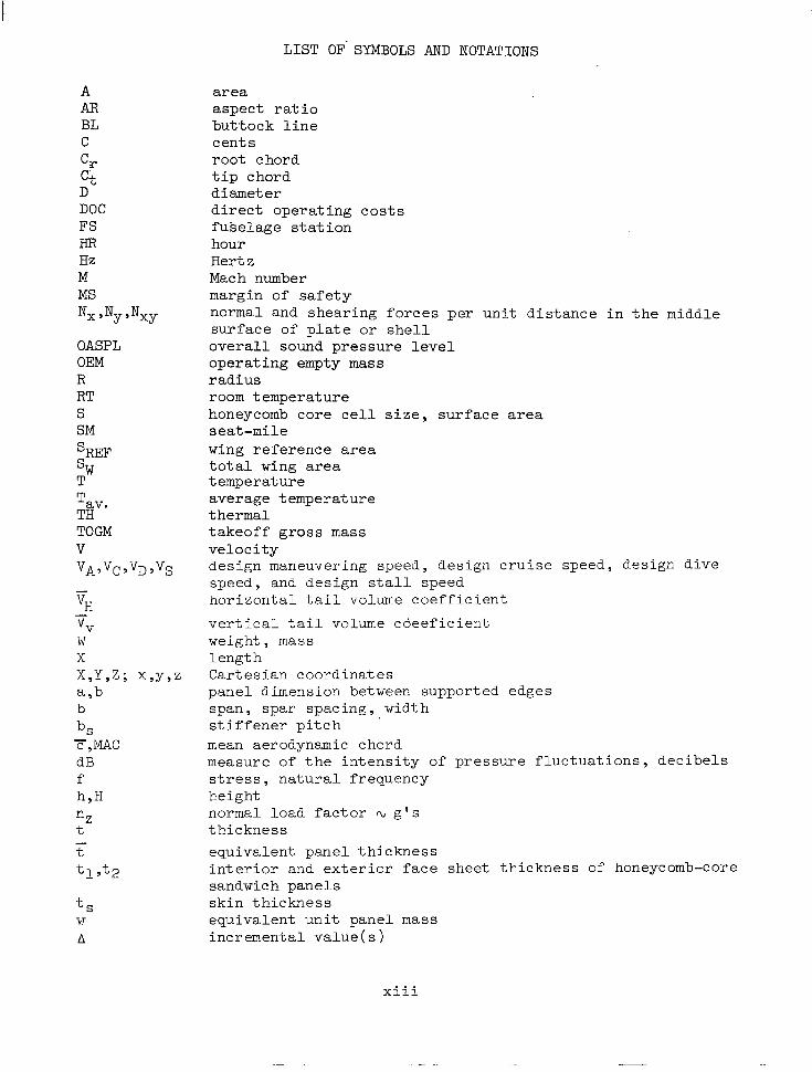
LIST OF- SYMBOLS AND NOTATIONS
A AR BL C c, C t D DOC FS HR Hz M MS Nx Jy Jxy
OASPL OEM R RT S SM S~~~ SW rn
nZ t
t S T.T
A
area aspect rat i o b u t t o c k l i n e cen t s root chord t i p chord diameter d i r e c t o p e r a t i n g c o s t s fu se l age s t a t ion hour Hertz Mach number margin of safety normal and shear ing forces per un i t d i s tance in the middle su r face o f p l a t e o r she l l o v e r a l l sound pressure level opera t ing empty mass r ad ius room temperature honeycomb c o r e c e l l s i z e , sur face area seat-mile wing re ference area t o t a l wing area temperature average temperature thermal takeoff gross mass ve loc i ty design maneuvering speed, design cruise speed, design dive speed, and design s t a l l speed ho r i zon ta l t a i l volume c o e f f i c i e n t
v e r t i c a l t a i l volume coee f i c i en t weight, mass length Cartesian coordinates panel dimension between supported edges span, spar spacing, width s t i f f e n e r p i t c h mean aerodynamic chord measure of t h e i n t e n s i t y of p re s su re f l uc tua t ions , dec ibe l s s t r e s s , na tu ra l f r equency height normal load factor Q g ’ s th ickness equivalent panel thickness i n t e r i o r and ex te r io r f ace shee t t h i ckness of honeycomb-core sandwich panels sk in th ickness equiva len t un i t pane l mass incremental value( s )
x i i i

EVALUATION OF STRUCTURAL DESIGN CONCEPTS
SUPERSONIC CRUISE AIRCRAFT FOR AN ARROW-TUNG
by I. F. Sakata and G. 17. Davis LOCKHEED-CALIFORNIA COMPANY
SUMMARY
An analytical study vas performed to determine the best structural approach for design of the primary wing and fuselage structure of a Mach 2.7 arrowwing supersonic cruise aircraft. The study encompassed an in-depth structural design of the NASA-defined baseline configuration, based on the specified design criteria and objectives, and consistent with the premise of near-term start-of-design. In addition, the study identified opportunities f o r structural mass reduction and resulted in recommendations for needed research and technology.
A spectrum of structural concepts that had been proposed or have found application for supersonic aircraft designs, such as the Anglo-French Con- corde supersonic transport, the Mach 3.0-plus Lockheed YF-12 aircraft, and the proposed Lockheed L-2000 and Boeing B-2707 supersonic transports, were evaluated. The evaluation involved systematic multi-disciplinary studies encompassing: airplane configuration refinement (including propulsion- airframe integration); design/manufacturing/cost studies; and the complex interactions between airframe strength and stiffness, static and dynamic loads, flutter, fatigue and fail-safe design, thermal loads, and the effects or' variations in structural arrangements, concepts and materials on these interactions. Due to the complex nature of these studies, extensive use vas made of computerized analysis programs, including Lockheed-California's inte- gra-ced NASTRAN-FAMAS structural analysis system.
The structural evaluation was conducted in two phases: (1) a design concept evaluation study vherein a large number of candidate structural con- cepts were investigated and evaluated to determine the most promising concepts, and (2) a detailed engineering design-analysis study of the selected struc- tural approach to define the critical design parameters and the estimated structural mass 02 the final design airplane.
The results of the design concept evaluation indicated that a hybrid design using a combination of a primarily chordwise-stiffened wing structure arrangement, with a biaxially stiffened (monocoque) arrangement for the wing tip to satisfy flutter requirements, would be the most efficient from a mass and cost standpoint. The wing tip construction selected was aluminum-brazed titanium honeycomb-sandwich. For the remainder of the wing, lowprofile convex-beaded surface panels of titanium alloy 6 u - 4 ~ were used, supported with discrete submerged spanvise titanium spar caps reinforced with boron- polyimide composite material. The fuselage vas a Ti-6Al-hV hat-stiffened design with supporting frames.

The r e s u l t a n t f i n a l d e s i g n a i r p l a n e s a t i s f i e s a l l the design object ives , including payload, service l i fe and range, and meets or exceeds the commer- c ia l a i rc raf t requi rements o f Federa l Avia t ion Regula t ion , Par t 25 (FAR 25) . The wing s t r u c t u r e was designed by a combination of strength, st iffness and minimum gage (foreign object damage) requirements, with no s i g n i f i c a n t impact from t h e Mach 2.7 temperature environment. The fuse lage s t ruc ture was designed by a combination of strength and fatigue, including cabin pressuriza- t i o n and elevated temperature effects.
The s tudy makes c lear the impor tance o f inc luding rea l i s t ic cons idera t ion of a e r o e l a s t i c e f f e c t s e a r l y i n t h e d e s i g n c y c l e f o r t h i s t y p e of a i r c r a f t . Signif icant s t ructure , over and above that required for s t rength, w a s added i n s e l e c t e d a r e a s t o remove f lu t t e r de f i c i enc ie s . In ad? . i t i on , t he po ten t i a l of computer-aided design methods for reducing the manpower and design calen- dar time was amply demonstrated. Finally, the study described above and re la ted supplementary inves t iga t ions ident i f ied a major po ten t ia l for s t ruc- tural mass reduction through the development and application of high tempera- ture composite materials; and t h e need f o r f u r t h e r improvement of aerodynamic performance through the use of active control devices and other configuration development.
2

INTRODUCTION
For the past several years , the Nat ional Aeronaut ics and Space Administration (NASA) Langley Research Center has been pmsuing a supersonic c r u i s e a i r c r a f t r e s e a r c h program to p rov ide sound t echn ica l bases fo r fu tu re c i v i l and mil i tary supersonic vehicles , including possible development of an environmentally acceptable and economically viable commercial supersonic t r anspor t .
The design of a s a t i s f a c t o r y advanced supersonic cruise a i rcraf t requires reduced s t ruc tura l mass f r ac t ions a t t a inab le t h rough app l i ca t ion o f new mater- ials an.d concepts, and advanced design tools. Configurations, such as the arrow-Iring , show promise from t h e aerodynamic standpoint; however , d e t a i l e d s t ruc tu ra l des ign s tud ie s a r e needed t o d e t e r m i n e t h e f e a s i b i l i t y o f con- s t r u c t i n g t h i s t y p e o f a i r c r a f t -crith s u f f i c i e n t l y 1017 s t r u c t u r a l mass.
The inves t iga t ion now being reported was conducted to subjec t p romis ing s t ruc tura l concepts to in -depth ana lyses , inc luding the more important environ- mental considerations t h a t could a f fec t the s e l e c t i o n o f t h e b e s t s t r u c t u r a l approach for design of primary Iring and fuselage structure of a given Mach 2.7 arrow-wing supersonic cruise aircraft, assuming a near-term start-of-design.
A spectrum of structural concepts were evaluated. The evaluation involved systematic multi-disciplinary studies encompassing: airplane configuration refinement, design/manufacturing/cost s tud ie s , and a s t ruc tu ra l eva lua t ion involv ing the complex in t e rac t ions between airframe s t r eng th and s t i f f n e s s , s t a t i c and dynamic l o a d s , f l u t t e r , f a t i g u e and fail-safe design, thermal loads , and the e f fec ts o f var ia t ions in s t ruc tura l a r rangements , concepts and mater ia l s on these in te rac t ions . The s t r u c t u r a l e v a l u a t i o n was conducted i n two phases: (1) a design concept evaluation study wherein a l a r g e number of candida te s t ruc tura l concepts were invest igated and evaluated to determine t h e most promising concepts, and ( 2 ) a detai led engineer ing design-analysis s tudy o f t he s e l ec t ed s t ruc tu ra l app roach t o de f ine t he c r i t i ca l des ign parameters and the es t imated s t ructural mass o f t h e f i n a l d e s i g n a i r p l a n e .
This repor t summarizes the s tudy made by the Lockheed-California Company and discusses the design methodology and r e su l t s . De ta i l desc r ip t ions o f t he analyses and subs tan t ia t ion o f the resu l t s a re p resented in Reference 1. (An executive summary of the s tudy vas presented in Reference 2; and a summary of the p roducib i l i ty t echnology s tud ies was presented in Reference 3.)
CONFIGURATION
The i n i t i a l t a s k v a s t h e e v a l u a t i o n and ref inement of the reference a i r c ra f t con f igu ra t ion i n t e rms o f aerodynamic performance and design.
3
Reference Configuration
The reference configurat ion shown in Figure 1 i s a d i s c r e t e wing-body a i rp lane wi th a low wing t h a t i s continuous under the fuselage and was derived from t h e NASA SCAT l5F configurat ion. The ex terna l shape of the a i rp lane was defined at the des ign l i f t coef f ic ien t by a computer card deck supplied by NASA. A s n o t e d i n t h e f i g u r e , t h e c o n f i g u r a t i o n i s based on the use o f four underwing turboje t engines , a hor izonta l t a i l volume coefficient of 0.055, and a wing t i p sveep angle of 64.6-degrees (1.13-rad). The a i rp lane incorpora tes v e r t i c a l f i n s on t h e wing, but does not include a canard or inboard leading- edge devices. Pitch control and trim i s provided by the horizontal t a i l .
Configuration Refinement
Several areas of concern were i d e n t i f i e d w i t h r e g a r d t o t h e r e f e r e n c e configurat ion, and ref inements to these areas were examined and appropriate changes incorpora%ed into the design.
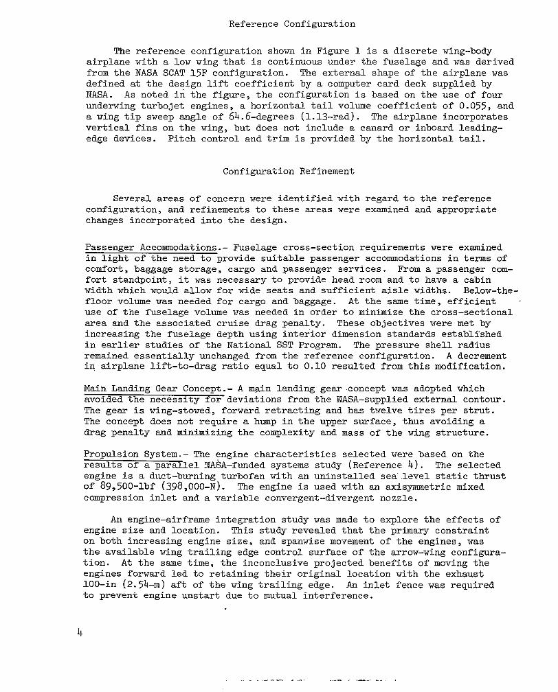
Passenger Accommodations.- Fuselage cross-section requirements were examined i n l i g h t o f t h e need t o provide sui table passenger accommodations in terms of comfort , baggage storage, cargo and passenger services. From a passenger com- fo r t s t andpo in t , it was necessary to provide head room and t o have a cabin width which would a l low fo r wide seats and s u f f i c i e n t aisle widths. Below-the- f l o o r volume was needed for cargo and baggage. A t t h e same t ime , e f f i c i en t use of tne fuse lage volume was needed in o rder to min imize the c ross -sec t iona l area and the associated cruise drag penal ty . These object ives were met by increasing the fuselage depth using inter ior dimension s tandards es tabl i ' shed i n earlier s tudies o f the Nat iona l SST Program. The p res su re she l l r ad ius remained essentially unchanged from the reference configuration. A decrement i n a i r p l a n e l i f t - t o - d r a g r a t i o e q u a l t o 0.10 r e su l t ed from th i s mod i f i ca t ion .
Main Landing Gear Concept.- A main landing gear -concept was adopted which avoided the necess i ty for devia t ions from t h e NASA-supplied external contour . The gear i s wing-stowed, forward retracting and has twelve t i res p e r s t r u t . The concept does not require a hump i n t h e upper surface, thus avoiding a drag penalty and minimizing the complexity and mass of t h e wing s t ruc tu re .
Propulsion System.- The eng ine cha rac t e r i s t i c s s e l ec t ed were based on t h e results of a p a r a l l e l YASA-funded systems study (Reference 4 ) . The se lec ted engine i s a duct -burn ing tu rbofan wi th an un ins ta l led sea . . l eve l s ta t ic th rus t of 89,500-lbf (398,000-N). The engine i s used with an axisymmetric mixed compression i n l e t and a variable convergent-divergent nozzle.
An engine-airframe integration study was made t o e x p l o r e t h e e f f e c t s o f engine s ize and locat ion. This s tudy revealed that the pr imary constraint on both increasing engine size, and spanvise movement of the engines , was t h e a v a i l a b l e wing t r a i l i n g edge cont ro l sur face o f the arrow-wing configura- t i o n . A t t h e same t i m e , the inconclusive projected benefi ts of moving t h e eng ines fo rward l ed t o r e t a in ing t he i r o r ig ina l l oca t ion w i th t he exhaus t 100-in (2.54-m) aft of t h e wing t r a i l i n g edge. An i n l e t f e n c e w a s required to p reven t eng ine uns t a r t due t o mutual interference.
4

5

Low-Speed Longi tudina l Charac te r i s t ics . - The low-speed pitch-up character- i s t i c s o f t h e arrow-wing were examined using an i n t e r a c t i v e computer graphics t echn ique t ha t s imu la t e s , i n real-time, the longi tudinal behavior of the a i rp lane response to cont ro l d i s turbances . The f e a s i b i l i t y of using the ho r i zon ta l t a i l as a p i t c h limiter t o p r o v i d e s a t i s f a c t o r y l o n g i t u d i n a l cont ro l whi le opera t ing in to the p i tch-up reg ion was invest igated. Findings showed t h a t i f adequate control authori ty w a s provided, it was p o s s i b l e t o provide au tomat ic p i tch l imi t ing capabi l i ty and good handl ing qua l i t i es . However, two requirements must be met: (1) a d e f i n i t e t a i l s i z e t o c e n t e r - of-gravi ty re la t ionship xust . be maintained, and (2 ) t h e p i t c h l i m i t e r s y s t e m mast be fa i l -operat ive. On the bas i s o f t hese cons ide ra t ions , a t a i l v o l m e coef f ic ien t o f 0 .07 i s t h e m i r i m u m t h a t would y i e l d a3 acceptable center-of- grav i ty range; in conjunct ion , the a i rp lane ba lance should be se t so t h a t t h e center-of-gravity i s at 55-percent MAC at t h e m a x i m u m landingimass.
Low-Speed L i f t Capabili t ies.- Configuration development studies explored app l i ca t ion o f l ead ing and t r a i l i ng edge devices with auxiliary tr imming surfaces (canar6-s and horizontal t a i l ) tcm provide schemes for supplementing t h e low-speed l i f t c a p a b i l i t i e s o f t h e arrow-wing planform. The objec t ive was t o maximize the usable l i f t a t take-off a t t i tudes consider ing in-ground e f f e c t s . Methods of low-speed p i t c h s t a b i l i t y improvement were a l so s tud ied This involved a i rplane balance, including the fuel system and i t s r e l a t e d tankage arrmgement. On t h e f i n a l c o n f i g u r a t i o n a change i n wing t i p sweep from 64.6-degrees (1.13-rad) as def ined by t h e NASA-supplied d a t a t o a 60-degree (1.05-rad) sweep was made. This change reduced the demands on t h e longi tudinal s tabi l i ty augmentat ion system and permit ted a more a f t center- of -gravi ty loca t ion wi th the ex is t ing hor izonta l t a i l power.
Final Configurat ion
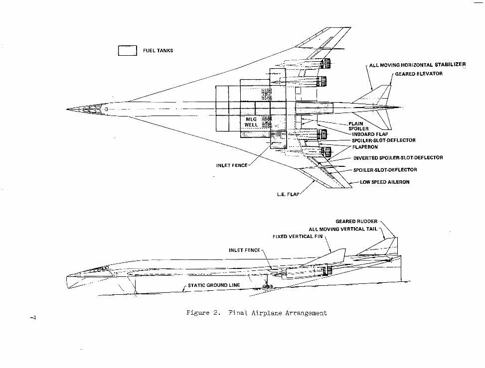
The f i n a l airplane arrangement i s shown on Figure 2. Geometric c h a r a c t e r i s t i c s are presented in Table 1. The a i rp lane has a design gross mass of 750,000-lbm (340,000-kg). The fuselage accommodates 234 passengers i n f i ve -ab reas t s ea t ing . The ove ra l l l eng th i s 296.9-ft (90.5-m). This includes a 119-in (3.02-m)- shortening of the fuselage t o compensate f o r t h e s t r u c t u r a l mass increase assoc ia ted wi th increas ing the fuse lage depth . The wing span i s 132.6-ft (40.4-m). The leading edge sweep of the wing t i p h a s been decreased t o 60-degrees (1.05-rad). The wing-mounted main landing gear employs a three-wheel axle des ign and re t rac ts in to a wel l j u s t outboard of t h e f h e l a g e . The length of the gear s t rut has been increased 19-in (0.48-m) t o accommodate the larger diameter of the selected engines .
The a i r c r a f t i s equipped with a three-axis s tabi l i ty augmentat ion system (SAS) with adequate redundancy to be fail-operative. The primary cont ro l sur faces are indica ted on Figure 2. An all-moving horizontal s t a b i l i z e r w i t h a geared e levator i s used for p i tch cont ro l . For yaw con- t r o l , a fuselage mounted all-moving v e r t i c a l t a i l with a geared rudder 2s . provided. The t a i l volume c o e f f i c i e n t s f o r t h e h o r i z o n t a l s t a b i l i z e r (V,) and t h e v e r t i c a l t a i l (vy) are 0.07 and 0.024 , respec t ive ly . The inboard wing f l a p s are used as l i f t devices a t low speed. Leading edge f laps are provided on t h e o u t e r wing for subsonic and t ransonic speeds, and a i l e rons on t h e t r a i l i n g edge f o r low speed. A t supersonic speeds, the inverted spo i l e r - s lo t de f l ec to r and spoi le r -s lo t def lec tors p rovide the p r imary ro l l cont ro l .
6
FUEL TANKS
ONTAL STABILIZER - GEARED ELEVATOR
INVERTED SPOILER-SLOT-DEFLECTOR
INLET FENCE SPOILER-SLOT-DEFLECTOR
*vx\\LOW SPEED AILERON
L.E. FLAP
GEAREDRUDDER
ALL MOVING VERTICAL TAIL FIXED VERTICAL FIN
INLET FENCE
Figure 2. Final Airplane Arrangement
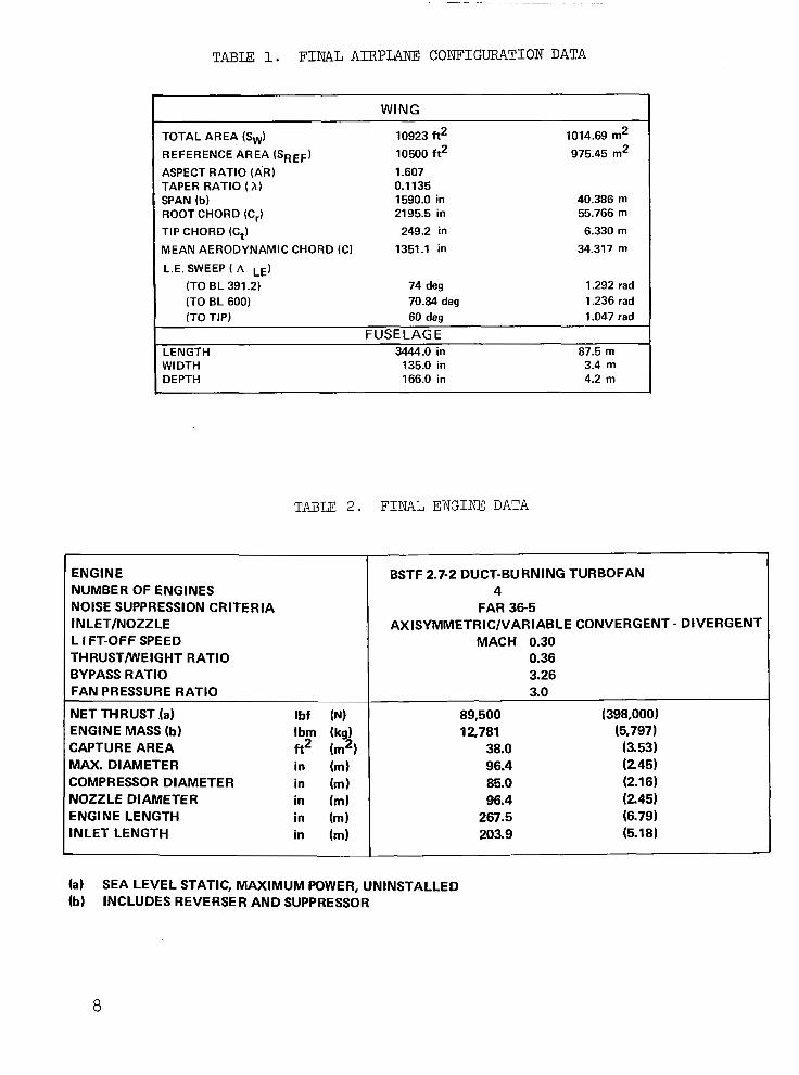
TABLE 1. FINAL AIRPLANE CONFIGURATION DATA
I WING
TOTAL AREA (Sw) REFERENCE'AREA (sREF) ASPECT RATIO (AR) TAPER RATIO ( A ) SPAN (b) ROOT CHORD (Cr) TIP CHORD (C,) MEAN AERODYNAMIC CHORD (C)
10923 ft2 10500 ft2
1.607 0.1 135 1590.0 in 2195.5 in 249.2 in
1351.1 in
1014.69 m2
975.45 m2
40.386 m 55.766 m 6.330 m
34.317 m
L.E. SWEEP ( A LE)
(TO BL 391.2) 74 deg 1.292 rad (TO BL 600) 70.84 deg 1.236 rad (TO TIP) 60 deg 1.047 rad
FUSE LAG E LENGTH 3444.0 in 87.5 m WIDTH 135.0 in 3.4 m DEPTH 166.0 in 4.2 m
r
TABU 2 . F I N A L E N G I N E DATA
ENGINE
AXISYMMETRIC/VARIABLE CONVERGENT - DIVERGENT INLET/NOZZLE . FAR 36-5 NOISE SUPPRESSION CRITERIA
4 NUMBER OF ENGINES BSTF 2.7-2 DUCT-BURNING TURBOFAN
THRUSThVEIGHT RATIO 0.36 BYPASS RATIO 3.26 FAN PRESSURE RATIO 3.0
NET THRUST (a) Ibf (N) 89,500 (398,000) ENGINE MASS (b) Ibm (kg) 12,781 (5,797) CAPTURE AREA ft2 (m2) 38.0 (3.53) MAX. DIAMETER in (m) 96.4 (245) COMPRESSOR DIAMETER in (m) 85.0 (2.16) NOZZLE DIAMETER in (m) 96.4 (2.45) ENGINE LENGTH in (m) 267.5 (6.79) INLET LENGTH in (m) 203.9 (5.18)
L I FT-OFF SPEED MACH 0.30
(a) SEA LEVEL STATIC, MAXIMUM POWER, UNINSTALLED (b) INCLUDES REVERSER AND SUPPRESSOR
8

Four duct-burning turbofan engines , each with 89,500-lbf (398,000-N) of u n i n s t a l l e d t h r u s t , are mounted i n under-wing pods having axisymmetric i n l e t s and t h r u s t r e v e r s e r s a f t o f t he wing t r a i l i n g edge. Engine configura- t i o n d a t a are presented in Table 2. The engines &re s i z e d t o p r o v i d e a t o t a l t h r u s t - t o - a i r p l a n e w e i g h t r a t i o o f 0.36 a t t a k e o f f . The engine mounts are loca ted a f t of the wing rear beam and are a t t a c h e d t o box beams which are c a n t i l e v e r e d o f f t h e wing s t r u c t u r a l box.
The major port ion of the lower fuselage i s u s e d f o r f u e l and baggage stowage, with baggage and other requirements establishing the forward l i m i t of fuel stowage. Forward of t h e f u e l stowage a rea , t he wing does not extend through the fuselage.
The tank arrangement shown i n F i g u r e 2 provides for a f u e l s t o r a g e capaci ty of 393,600-lbm (178,500-kg). Based on previous studies relating to fue l conta inment and management requi rements for supersonic c ru ise a i r c r a f t , it w a s e l e c t e d t o s t o w a s i g n i f i c a n t p o r t i o n o f t h e t o t a l f u e l w i th in t he wing cen te r s ec t ion . The 16-tank system w a s des igned to t ake advantage of the "protected-volume" of approximately 43-percent of the total s to rage capac i ty . In t h i s l oca t ion , t he uppe r su r f ace w a s exposed t o t h e cooled and controlled environment of the fuselage cabin while the wing lower sur face w a s shielded from the outslide airstream by a f a i r ing ex tend ing below and separa ted from the lower surface.
Fuel management schedul ing for a i rplane center-of-gravi ty control w a s spec i f i ca l ly p l anned t o maximize the ava i l ab le hea t s ink capac i ty of t h e f u e l by emptying t h e exposed outboard tanks as e a r l y as p o s s i b l e i n t h e f l i gh t . Add i t iona l cons ide ra t ions i nc luded fue l u sage t o pe rmi t t he air- c r a f t t o c r u i s e w i t h a minimum t r i m drag penal ty . The landing and reserve f u e l w a s l o c a t e d i n t h e p r o t e c t e d f u s e l a g e a r e a .
DESIGN CRITERIA
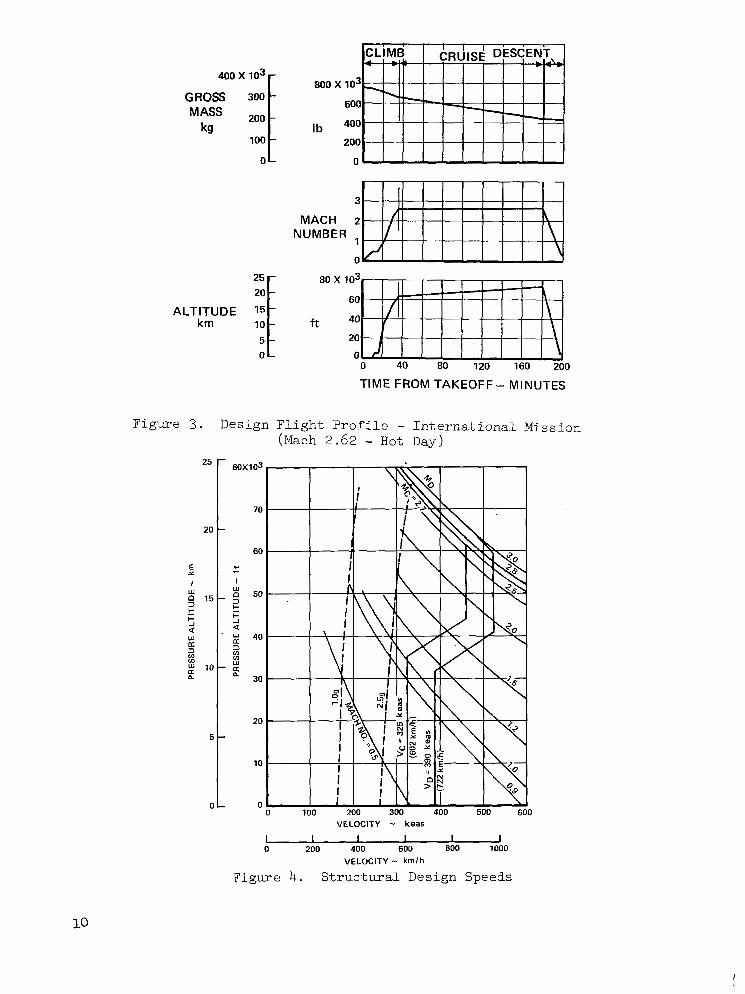
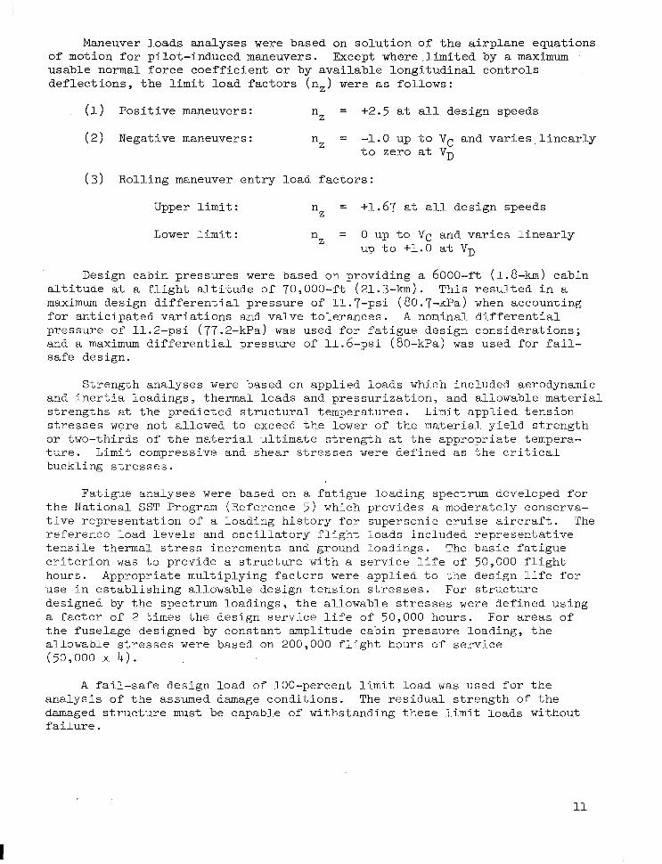
Evaluat ion of s t ructural concepts for the Mach 2.7 supersonic cruise a i r c r a f t w a s based on an a i r c r a f t w i t h an economic l i f e of 15 years and a s e r v i c e l i f e o f 50,000 fl ight hours, with the environment determined from a des ign f l i gh t p ro f i l e fo r an i n t e rna t iona l mi s s ion . The i n t e r n a t i o n a l m i s - s ion (F igure 3 ) i s approximately 3 .4 hours in durat ion; three-quarters of tha t t ime, o r 2 .5 hours , i s a t Mach 2.62 (Hot Day) c r u i s e .
For design purposes , a maximum t a x i mass of 750,000-lbm (340,000-kg) , a maximum landing mass of 420,000-lbm (190,000-kg) , a payload of 49,000-lbm (22,000-kg), and a design range of 4200-nmi (7800-h ) were s p e c i f i e d f o r t h e a i r p l a n e .
The design equivalent a i rspeeds shown i n F i g u r e 4 were s e l e c t e d t o provide an operat ional envelope compat ible with the design f l ight prof i le and sa t i s fy ing the requi rements o f FAR 25. The s t r u c t u r a l d e s i g n c r u i s e speed (V,) w a s s e l ec t ed as the planned operat ing speed in c l imb, cruise and descent. The design dive speed (V,) w a s s e l e c t e d t o p r o v i d e a margin of sa fe ty for the inadver ten t l a rge excurs ions in excess o f opera t ing speed.
9'
400 x 103
100
800 X
Ib
25
20
ALTITUDE 1s km 10
5 0
0 40 80 120 160 200
TIME FROM TAKEOFF- MINUTES
Figure 3. Design Flight Profile - International Mission (Mach 2.62 - Hot Day)
VELOCITY - keas
I I I I I I 0 200 400 600 800 1000
VELOCITY - km/h
Figure 4. Structural Design Speeds
Maneuver loads analyses were based on so lu t ion o f t he a i rp l ane equa t ions of motion for pilot-induced maneuvers. Except where.limited by a maximum usable normal force coeff ic ient or by ava i l ab le l ong i tud ina l con t ro l s de f l ec t ions , t he l i m i t load factors (n , ) were as fol lows:
(1) Pos i t ive maneuvers: n = +2.5 a t a l l design speeds Z
(2) Negative maneuvers : nZ = -1.0 up t o Vc a n d v a r i e s , l i n e a r l y t o z e r o a t VD
(3 ) Rol l ing maneuver en t ry l oad f ac to r s :
Upper l i m i t : n = +1.67 at a l l design speeds
Lower l i m i t : n = 0 up t o VC and va r i e s l i nea r ly
Z
Z UP t o +1.0 a t VD
Design cabin pressures were based on providing a 6000-ft (1.8-km) cabin a l t i t u d e a t a f l igh t a l - t i tude o f 70 ,000-f t (21.3-km). T h i s r e s u l t e d i n a maximum des ign d i f f e ren t i a l p re s su re of 11.7-psi (80.7-kPa) when accounting f o r a n t i c i p a t e d v a r i a t i o n s and valve tolerances. A nominal d i f f e r e n t i a l pressure of 11.2-psi (77.2-kPa) w a s used for fa t igue design considera , t ions; and a maximum di f fe ren t ia l p ressure o f 11 .6-ps i (SO-kPa) was used for fa i l - safe design.
Strength analyses were based on applied loads which included aerodynamic and ine r t i a l oad ings , t he rma l l oads and p res su r i za t ion , and allowable material s t r eng ths a t the p red ic t ed s t ruc tu ra l t empera tu res . L i m i t appl ied t ens ion s t r e s s e s were not a l lowed to exceed the lower of the mater ia l y ie ld s t rength or two-thirds of the material u l t ima te s t r eng th a t the appropriate tempera- t u r e . L i m i t compressive and shear stresses were def ined as t h e c r i t i c a l buck l ing s t r e s ses .
Fat igue analyses were based on a fatigue loading spectrum developed for the Nat iona l SST Program (Refercnce 5) which provides a moderately conserva- t i ve r ep resen ta t ion o f a load ing h i s to ry fo r supe r son ic c ru i se a i r c ra f t . The r e fe rence l oad l eve l s and o s c i l l a t o r y f l i g h t l o a d s i n c l u d e d r e p r e s e n t a t i v e t e n s i l e t h e r m a l s t ress increments and ground loadings. The bas i c f a t igue c r i t e r i o n w a s t o p rov ide a s t ruc tu re w i th a se rv ice l i f e of 5O,OOO f l i g h t hours . Appropriate mult iplying factors were a p p l i e d t o t h e d e s i g n l i f e f o r u se i n e s t ab l i sh ing a l lowab le des ign t ens ion stresses. For s t r u c t u r e designed by the spec t rum load ings , t he a l lowab le s t r e s ses were def ined using a f a c t o r of 2 times the des ign s e rv i ce l i f e o f 50,000 hours. For areas of the fuselage designed by constant ampli tude cabin pressure loading, the a l lowab le s t r e s ses w e r e based on 200,000 f l i gh t hour s o f s e rv i ce (50,000 x 4 ) .
A fail-safe des ign load of 100-percent l i m i t load w a s u s e d f o r t h e ana lys i s o f t he assumed damage condi t ions . The r e s idua l s t r eng th o f t he damaged s t r u c t u r e must be capable of withstand-ing these l i m i t loads without f a i l u r e .
11

The s e l e c t i o n of minimum gages for reg ions no t des igned to spec i f ic s t r e n g t h or fatigue requirements was based on cons idera t ion of the s t ruc tura l concept employed, fabrication constraints, and foreign object damage (FOD) e f f e c t s .
STRUCTURAL DESIGN CONCEPTS
A spec t rum of s t ruc tura l approaches for p r imary s t ruc ture des ign tha t have found application or had been proposed for supersonic a i rcraf t , such as t h e Anglo-French Concorde supe r son ic t r anspor t , t he Mach 3.0-plus Lockheed YF-12, and the proposed Lockheed L-2000 and Boeing B-2707 supersonic t rans- p o r t s , were sys temat ica l ly eva lua ted . for the g iven conf igura t ion and des ign c r i t e r i a .
Design and manufactur ing concepts s tudies es tabl ished feasibi l i ty of the application of advanced manufacturing techniques to large-scale produc- t ion. Basic design parameters and design guidelines were established for each structural arrangement and concept to provide consistency between manu- factur ing design s tudies and analyses . These s tudios examined t h e f a b r i c a t i o n f e a s i b i l i t y down t o t h e s m a l l e s t subcomponent l e v e l , and involved the design of sLruc tura1 concepts tha t represented bo th s t ruc tura l e f f ic iency and appl i - c a b i l i t y t o advanced fabr icat ion techniques.
Candidate materials included. both metall ic and composite material systems. Alpha-Beta (Ti -6Al-bV) and Beta (Beta C ) t i t an ium a l loys , bo th annealed and. so lu t ion t rea ted and aged , were e v a l u a t e d t o i d e n t i f y t h e i m p o r t a n t c h a r a c t e r i s t i c s f o r minimum mass designs as cons t ra ined by t h e spec i f i ed s t ruc tu ra l app roach and l i f e r e q u i r e m e n t s .
The composite materials considerec included both organic (graphi te- polyimide, boron-polyimide) and metallic (boron-aluminum) matrix systems. Se lec t ive re inforcement o f the bas ic meta l l ic s t ruc ture w a s considered as the appropr ia te l eve l o f composi te ' appl ica t ion for the near-term design. Furthermore, based on the p r inc ip l e o f maximum r e t u r n f o r minimum cos t and r i s k , t h e a p p l i c a t i o n was p r imar i ly un id i r ec t iona l r e in fo rc ing o f members carrying pr imary axial loads, such as s t r i n g e r s , s p a r c a p s , r i b c a p s and s t i f f e n e r s o f wing panel designs.
Wing Structure Concepts
The s t ruc tura l des ign concepts for the wing primary load-carrying struc- ture a r e shown i n F i g u r e 5 .
Monocoque cons t ruc t ion (F igure 5a) cons is t s o f b iax ia l ly-s t i f fened . pane ls which support the princj-pal loads i n both the span and chord d i rec t ions . The substructure arrangement consis ts o f bo th mu l t i r i b and multispar designs.
The monocoque cons t ruc t ion has a smooth s k i n t h a t r e E u l t s i r minimum aerodynamic drag. However, thermal stresses are absorbed by the pr imary s t ruc tura l e lements wi th min imal re l ie f . Biax ia l loading resu l t s in reduced f a t igue a l lowab les ; ye t c r i t i ca l i t y o f o the r des ign pa rame te r s o f t en con t ro l s minimum mass s t ruc tu ra l des igns .
12

PANEL STRUCTURAL CONCEPTS w u HONEYCOMB-CORE
SANDWICH
7-ARC
( A ) MONOCOQUE (BIAXIALLY-STIFFENED)
MU1 0
a CIRCULAR-ARC CIRCUL TRUSS .A R
PANEL STRUCTURAL CONCEPTS
W
CONCAVE BEADED SKIN
___v
CIRCULAR-ARC
G=77 CIRCULAR-ARC CONVEX BEADED SKIN
m TRAPEZOIDAL CORRUGATION CONCAVE BEADED SKIN
m- -ARC BEADED CORRUGATION
CONCAVE BEADED SKIN
( C ) CHORDWISE-STIFFENED
C
0 TRUSS TRUSS 0 CI RCU L
CIRCULAR-ARC
PANEL STRUCTURAL CONCEPTS
111 ZEE STIFFENED
Tn_ INTEGRAL ZEE
iJ"J HAT STIFFENED
"T INTEGRALLY STIFFENED
.AR-ARC
(8B) SPANWISE-STIFFENED
MU1 a 0
STRUCTURAL CONCEPTS
"J1p REINFORCED PANEL
'& REINFORCED CAPS
"
CI RCULAR-ARC TRUSS
0 CIRCULAR-ARC
( 0 ) CHORDWISE-STIFFENED COMPOSITE REINFORCED CONCEPTS
w I-J Figure 5 . Wing Structure Concepts
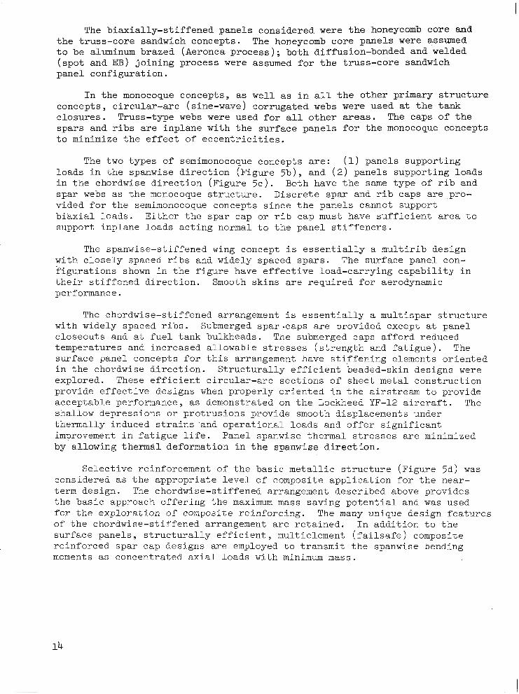
The biaxially-stlffened panels considered were the honeycomb core and the truss-core sandwich concepts. The honeycomb core panels were assumed to be aluminum brazed (Aeronca process); both diffusion-bonded and welded (spot and EB) joining process were assumed for the truss-core sandwich panel configuration.
In the monocoque conceptsy as well as in all the other primary structure concepts, circular-arc (sine-wave) corrugated webs were used at the tank closures. Truss-type webs were used for all other areas. The caps of the spars and ribs are inplane with the surface panels for the monocoque concepts to minimize the effect of eccentricities.
The two types of semimonocoque concepts are: (1) panels supporting loads in the spanwise direction (Figure 5b), and (2) panels supporting loads in the chordwise direction (Figure 5c). Both have the same type of rib and spar webs as the monocoque structure. Discrete spar and rib caps are .pro- vided for the semimonocoque concepts since the panels cannot support biaxial loads. Either the spar cap or rib cap must have sufficient area to support inplane loads acting normal to the panel stiffeners.
The spanwise-stiffened wing concept is essectially a multirib design with closely spaced ribs and widely spaced spars. The surface panel con- figurations shown in the figure have effective load-carrying capability in their stiffened d.irection. Smooth skins are required for aerodynamic performance.
The chordwise-stiffened arrangement is essentially a multispar structure with widely spaced ribs. Submerged spar-caps are provided except at panel closeouts and at fuel tank bulkheads. The submerged caps afford reduced temperatures and increased allowable stresses (strength and fatigue). The surface ganel concepts for this arrangement have stiffening elements oriented in the chordwise direction. Structurally efficient beaded-skin designs were explored. These efficient circular-arc sections of sheet metal construction provide effective designs when properly oriented in the airstream to provide acceptable performance, as demonstrated on the Lockheed YF-12 aircraft. The shallow depressions or protrusions provide smooth displacements under thermally induced strains .and opcratior-a1 loads and offer significant improvement in fatigue life. Panel spanwise thermal stresses are minimized by allowing thermal deformation in the spanwise direction.
Selective reinforcement of the basic metallic structure (Figure 513) was considered as the appropriate level of composite application for the near- term design. The chordwise-stiffened arrangement described above provides the basic approach offering the maximum mass saving potential and was used for the exploration of composite reinforcing. The many unique design features of the chordwise-stiffened arrangement are retained. In addition to the surface panels, structurally efficient, multielement (failsafe) composite reinforced spar cap designs are employed to transmit the spanwise bending moments as concentrated axial loads with minimum nass.
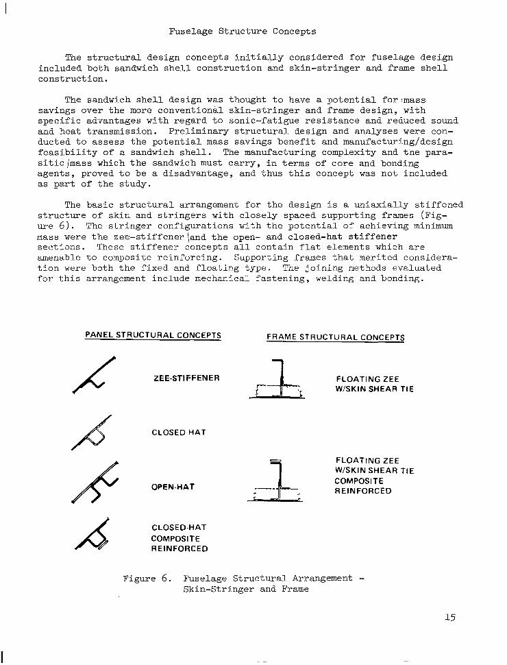
Fuselage Structure Concepts
The structural design concepts initially considered for fuselage design included both sandwich shell construction and skin-stringer and frame shell construction.
The sandwich shell design was thought to have a potential for'mass savings over the more conventional skin-stringer and frame design, with specific a&iantages with regard to sonic-fatigue resistance and reduced sound and heat transmission. Preliminary structural design and analyses were con- ducted to assess the potential mass savings benefit and manufacturing/design feasibility of a sandwich shell. The manufacturing complexity and tne para- sitic \mass which the sandwich must carry, in terms of core and bonding agents, proved to be a disadvantage, and thus this concept was not included as part of the study.
The basic structural arrangement for the design is a uniaxially stiffened structure of skin and stringers with closely spaced supporting frames (Fig- ure 6). The stringer configurations with the potential of achieving minimum mass were the zee-stiffener land the open- and closed-hat stiffener sections. These stiffener concepts all contain flat dements which are amenable to composite reinforcing. Supporting frames that merited considera- tion were both the fixed and floating type. The joining nethods evaluated for this arrangement include mechanical fastening, welding and bonding.
PANEL STRUCTURAL CONCEPTS FRAME STRUCTURAL CONCEPTS
CLOSED-HAT
FLOATING ZEE W/SKIN SHEAR TIE COMPOSITE REINFORCED
CLOSED-HAT COMPOSITE REINFORCED
Figure 6. Fuselage Structural Arrangement - Skin-Stringer and Frame
DESIGN METHODOLOGY
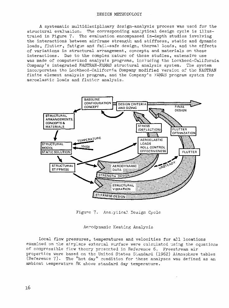
A systematic multidisciplinary design-analysis process was used for the structural evaluation. The corresponding analytical design cycle is illus- trated in Figure 7. The evaluation encompassed in-depth studies involving the interactions between airframe strength and stiffness, static and dynamic loads, flutter, fatigue and fail-safe design, thermal loads, and the effects of variations in structural arrangement, concepts and materials on these interactions. Due to the complex nature of these studies, extensive use was made of computerized analysis programs, including the Lockheed-California Company's integrated NASTRAN-F&IAS structural analysis system. The system incorporates the Lockheed-California Company modified version of the NASTRAN finite element analysis program, and the Company's F A S program system for aeroelastic loads and flutter analysis.
... _..... . . . . . . . . . . . . . . . . . . . . . . . . .................................................... .... . . . . . . . . . . . . . . . . . . . . . . . . . .. .. . . . . . . . . . . . . . . . . . . . . . . ...... ...:. . . . ... . . . . .. , ...
fl 7
....
CONCEPTS & I M A T F R l A l S I I STRUCTURAL
ARRANGEMENTS,(
Figure 7. Analytical Design Cycle
Aerodynamic Heating Analysis
Local flow pressures, temperatures and velocities for all locations examined on the airplane external surface were calculated using the equations of compressible flow theory presented in Reference 6. Freestream air properties were based on the United States Standard (1962) Atmosphere tables (Reference 7). The "hot day" condition for these analyses was defined as an ambient temperature 8K above standard day temperature.
16
Heat transfer to the interior structure was determined using Lockheed's thermal analyzer program. Wing-structure temperatures were calculated using network mod.els of the wing box, including representation of the upper and lower surface panels and the vertical webs. Heat transfer within the wing box included conduction, radiation, and convection to boundary layer air when leakage was a factor; and for fuel tank areas, convection to fuel and fuel vapor. The fuselage-structure tenperatures were calculated wing a network model of the fuselage shell, including the skin, frame, insulation and inner cabin wall. Heat transfer to the frame included conduction and radiation from the outer skin panels, and conduction from the surrounding insulation. Boundary conditions at the inner cabin wall included convectton to the cabin air and radiation to the cabin interior.
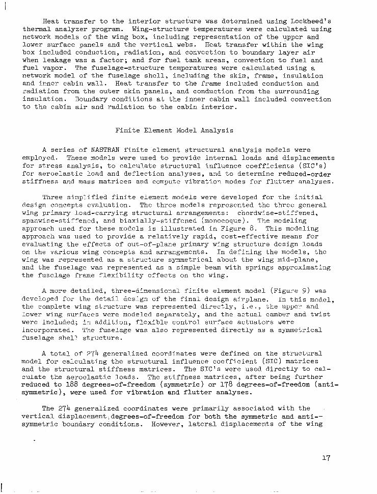
Finite Element Model Analysis
A series of NASTRAN finite element structural analysis models were employed. These models were used to provide internal I.oads and displacements for stress analysis, to calcu~.ate structural influence coefficients (SIC'S) for aeroelastic load and deflection analyses, and to determine reduced-order stiffness and mass matrices and compute vibration modes for fl.utter analyses.
Three simplified finite element models were developed fcr the initial design concepts evaluation. The three models represented the three general wing primary load-carrying structural arrangements: chordwise-stiffened, spanwise-stiffened, and biaxially-stiffened (monocoque). The modeling e.pproach used for these models is illustrated in Figure 8. This modeling approach was used to provide a relatively rapid, cost-effective means for evaluating the effects of out-of-plane primary wing structure design loads on the various wing concepts and arrangements. In defining the mod.els, the wing was represented as a structure symmetrical about the wing mid-plane, and the fuselage was represented as a simple beam with springs approximating the fuselage frame flexihili.ty effects on the wing.
A more detailed, three-dimensional finite element model (Figure 9 ) was developed for the detail design of the final design airplane. In this model, the complete wing structure was represented dj.rectly, i.e., the upper and lower wing surfaces were modeled separately, and the actual camber and twist were included; in addition, flexible control surface actu-ators were incorporated. The fuselage was also represented directly as a symmetrical fuselage shell structure.
A total of 274 generalized coordinates were d'efined on the structural model for calculating the structural influence coefficient (SIC) matrices and the structural stiffness matrices. The SIC'S were used directly to cal- culate the aeroelastic loads. The stiffness matrices, after being further reduced to 188 degrees-of-freedom (symmetric) or 178 degrees-of-freedom (anti- symmetric), were used for vibration and flutter analyses.
The 274 generalized coordinates were primarily associated with the vertical displacement,degrees-of-freedom for both the symmetric and anti-- symmetric bou.ndary conditions. However, lateral displacements of the wing

WING PLANFORM IDEALlZATlO
WING MEDIAN PLANE
SECTION A-A WING/FUSELAGE IDEALIZATION
Figure 8. F i n i t e Element S t r u c t u r a l Model f o r Design Concept Evaluation
I 715 GRIDPOINTS 2450 ELEMENTS 2200 DEGREES - OF - FREEDOM
Figure 9 . F i n i t e Element S t r u c t u r a l Model for Detail Design-Analysis
18

v e r t i c a l f i n were a lso inc luded . In addi t ion , l a te ra l d i sp lacements o f the fuselage were included for the antisymmetric boundary condition.
Aeroelast ic Loads Analysis
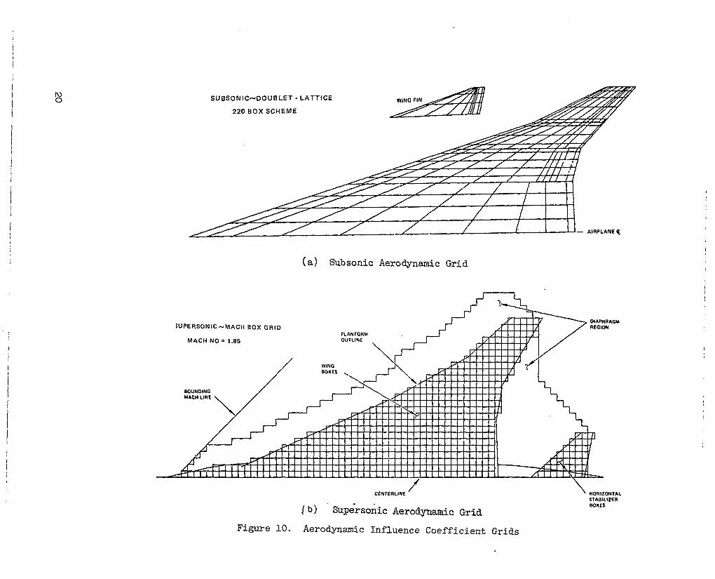
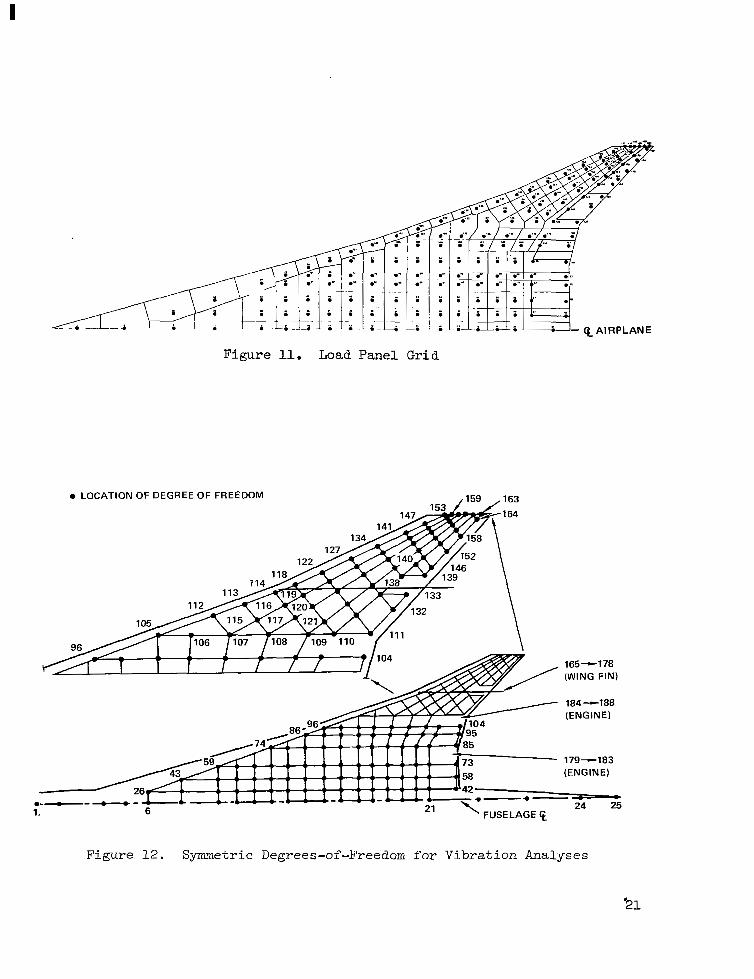
Net ae roe la s t i c l oads were determined a t p re se l ec t ed f l i gh t cond i t ions by combining the d e t a i l e d d i s t r i b u t i o n s of a i r l o a d s and iner t ia loads, and account- ing for t h e airframe f l e x i b i l i t y effects. The subsonic and supersonic airload d i s t r i b u t i o n s were determined using t h e D i r e c t Load Line Element (DDLE) and t h e Mach Box methods, respectivelx. The DDLE method i s t h e o r e t i c a l l y t h e same as t h e Doublet Latt ice method of Reference 8; t h e Mach Box method i s d e s c r i b e d i n Reference 9. Typical aerodynamic-influence-coefficient ( A I C ) g r id s u sed fo r the determination of subsonic and supersonic aerodynamics are shown i n F i g u r e LO. The aerodynamic loads vere transformed from the A I C g r i d t o t h e l o a d p a n e l g r i d shopm i n Figure 11. The above load-panel-point grid coincides with the struc- tura l - inf luence-coef f ic ien t (SIC) g r id u sed on t h e s t r u c t u r a l model.
Iner t ia data f o r t h e a i r p l a n e were determined for the operating mass empty, t he pay load and t he fue l d i s t r ibu t ions . Ine r t i a l oads fo r the var ious design load condi t ions were derived from these data.
Vibrat ion and Flut ter Analysis
The v ibra t ion ana lyses employed a general ized coordinate system that vas d i r ec t ly r e l a t ed t o t he s t ruc tu ra l i n f luence coe f f i c i en t (S IC) sys t em, bu t reduced i n t h e number of degrees-of-freedom. The netvork of coorCinates for t h e symmetric condition (Figure 1 2 ) contained 188 degrees-of-freedom. One- hundred and seventy-eight degrees-of-freedom were used for the ant isymmetr ic boundary condition. The stiffness ma t r i ces fo r t he v ib ra t ion ana lyses were obtained from the l a rge r o rde r s t i f fnes s ma t r i ces co r re spond ing t o t he SIC network using Guyan reduction techniques. The modal analyses were performed using the Givens method con ta ined i n NASTWT. The Givens method was se l ec t ed a f t e r i nves t iga t ing t he accu racy and computational time o f t h i s method, t h e Inverse Power method a l s o a v a i l a b l e i n NASTRAN, and t h e FAMAS &R method.
The s t i f fnes s ma t r i ces fo r each s t ruc tu ra l a r r angemen t , as derived from the f ini te e lement models , were combined wi th t he appropr i a t e i ne r t i a ma t r i ces t o cornpute t h e symmetric and antisymmetric eigenvectors and eigenvalues of tne f ree- f ree a i rp lane . The i n e r t i a m a t r i c e s were formed f o r two a i rp lane condi t ions only: the operat ing mass empty ( O M E ) , and t h e f u l l - f u e l and full- payload (FFFP). Tnese conditions represent the extremes of minimum and maxi- rr~urfl mass; no intermediate mass condi t ions were examined. I n g e n e r a l , f i f t y v ib ra t ion modes were ext rac ted f rom each v ibra t ion so lu t ion for use in the f l u t t e r a n a l y s e s and optimizations.
Steady and unsteady aerodynamic influence coefficients ( A I C ' s ) were ca l cu la t ed fo r Mach 0.60, 0.90, 1 - 2 7 and 1.85. The A I C ' s were computed f o r the v ing , the wing v e r t i c a l f i n , and empennage surfaces. These A I C ' s were adjus ted , vhen r e q u i r e d , t o r e f l e c t s t e a d y - s t a t e l i f t c o e f f i c i e n t s and aero- dynamic centers obtained from nind tunnel force data. The Mach 0.60 and 0.90
!
Iu 0 S U B S O N I C ~ D O U B L E T - LATTICE
220 BOX SCHEME
(a) Subsonic Aerodynamic Grid
CCNlERLINE ' ' HOR1ZONTAL SlAElLlZEA BOXES
Figure 10. Aerodynamic Inf luence Coeff ic ient Grids
I
-. - QAIRPLANE
Figure 11. Load Panel Grid
0 LOCATION OF DEGREE OF FREEDOM
165-178 (WING FIN)
184-188 (ENGINE)
179-183 (ENGINE)
.~,-."_~-&"""-CC--L-C-CI-L-CC~- -*- - - 1. 6
24 25
Figure 12. Symmetric Degrees-of-Freedom for Vibration Analyses

AIC ca lcu la t ions accoun ted fo r t he i n t e r f e rence between t h e wing and t h e wing v e r t i c a l f i n ; t h e Mach 1.25 and 1.85 AIC's d i d n o t i n c l u d e t h i s e f f e c t . Fuselage aerodynamics were not inc luded in these ana lyses .
The f l u t t e r analyses xere conducted using the method of solut ion des- c r ibed in Reference 1 0 as t h e p-k method. This method i s c o n t a i n e d i n t h e FAMAS system and results i n a so lu t ion which determines rate of decay and frequency for preselected values of speed and provides matched a l t i tude, Mach number and reduced frequency for each mode a t each prese lec ted ve loc i ty . To ensure convergence i n t h e f l u t t e r solut ions, twenty or more v i b r a t i o n modes and n ine or more reduced frequencies were used i n a l l f l u t t e r analyses .
An i n t e r a c t i v e computer graphics program, GFAM, was u s e d f o r f l u t t e r opt imizat ion. The GFAM program i n t e r a c t i v e l y d e t e r m i n e s t h e s e n s i t i v i t y o f t h e f l u t t e r speed t o changes in selected des ign va r i ab le s , i . e . , mass and s t i f f - ness changes within selected des ign reg ions ; and thereby opt imizes the placement of addi t iona l mass a n d / o r s t i f f n e s s t o c o r r e c t any f l u t t e r d e f i c i e n c i e s w h i l e minimiz ing the to ta l mass. An abbreviated descr ipt ion of the equat ions, method of solut ion, and opt imizat ion procedure i s presented in Reference 11. I n t h e i n i t i a l o p t i m i z a t i o n s t u d i e s , t h e d e s i g n r e g i o n s were s e l e c t e d t o provide a general assessment of the most e f f e c t i v e d i s t r i b u t i o n o f m a t e r i a l i n -the wing s t r u c t u r e . For t h e s e s t u d i e s , t h e wing planform w a s divided in to t en r eg ions (F igu re l 3 a ) , which inc luded the two engine support beam locat ions. Also shown (Figure 13b) i s a more r e f ined des ign r eg ion s e l ec t ion which w a s used for de ta i led op t imiza t ions o f the wing t i p s t r u c t u r e ( w h i c h was de te rmined to be one of t he most e f f e c t i v e r e g i o n s for a d d i t i o n a l s t ruc- ture to ach ieve t he des i r ed f l u t t e r speeds) .
Point Design Analysis
The candidate wing and fuselage structure design concepts were subjected to in -depth s t ruc tura l ana lyses us ing a point design approach. Representative s t r u c t u r a l r e g i o n s i n t h e wing and fuse lage were se l ec t ed as point design reg ions . For each reg ion , un i t s t ruc tures were def ined us ing the candida te concepts. The design load; temperature, and acoustic environments were then determined a t these po in t des ign reg ions and used i n de ta i led des ign ana lyses of t h e c a n d i d a t e c o n c e p t s t o e s t a b l i s h m i n i m u m mass designs.
Six point design regions were dz f ined fo r t he .wing s t ruc tu re (F igu re 14a). The regions were i d e n t i f i e d by their corresponding NASTRAN panel element number. A s i n d i c a t e d i n t h e f i g u r e , o n l y t h r e e o f t h e s e were used i n t h e i n i t i a l screening of the design concepts ; a l l s i x were used for the subse- quent de ta i l concept eva lua t ion and the engineer ing des ign ana lyses . Four Doint design regions were used for eva lua t ing the fuse lage concepts (F ig- n e 14b) . These were loca ted a t fuselage s ta t ions (FS) 750, 2000, 2500 and 3000 fo r t he des ign concep t s eva lua t ion ; t he equ iva len t l oca t ions fo r t he engineering design-analyses were FS 900, 1910, 2525 and 2900.
The u n i t s t r u c t u r e s f o r t h e wing box inc luded sur face pane l s t ruc ture , spars and. r i b s , and associated non-optimum i t ems . S imi l a r ly , t he un i t fu se l age s t ruc tu res i nc luded bo th t he fu se l age she l l s t ruc tu re , sk in and s t r i n g e r s , and the suppor t ing frcme s t r u c t u r e .
22
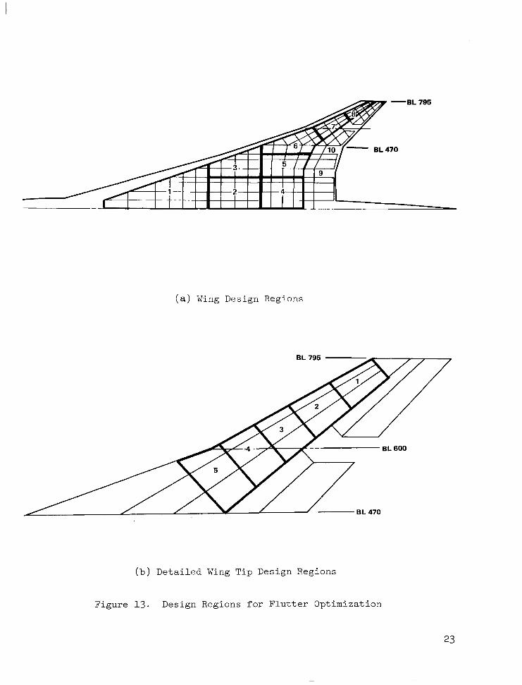
( a ) Wing Design Regions
(b) Detailed Wing Ti9 Design Regions
Figure 13. Design Regions for Flutter Optimization

FS 1955 (49.7)
1865
FS 2565 (65.2)
2485 Fs I ~ ~~
(a) WING POINT DESIGN REGIONS
~ , 4 1 0 3 6
2560 2660 2784 (65.0) (67.6) (70.7)
FS FS FS FS 750 2000 2500 3000 (19.1 1 (50.8)
I I I I
/ -
4" """"
(b) FUSELAGE POINT DESIGN REGIONS
-Q-
The u n i t s t r u c t u r e s a t each po in t des ign reg ion w e r e ana lyzed fo r u l t imate s t rength and fa t igue requi rements cons ider ing inp lane loads f rom the f in i te e lement ana lyses , normal loads assoc ia ted wi th aerodynamic p res - sure and/or fuei-head ine r t i a , and temperatures and temperature gradients r e s u l t i n g from t h e aerodynamic heating analyses. Computerized stress a n a l y s i s programs which incorporated optimization subroutines were used t o d e f i n e t h e minimum-mass propor t ions o f the candida te pane l concepts (Reference 1). The strength-sized components were a l s o s u b j e c t e d t o a fail-safe a n a l y s i s t o e n s u r e t h a t t h e s t r u c t u r e , i.n the p resence o f an assumed damage condi t ion , w a s capable of suppor t ing t he damage tolerance design load of 100-percent l i m i t load .
For t h e s o n i c f a t i g u e e v a l u a t i o n , d e s i g n c h a r t s a p p l i c a b l e t o t h e two d i f f e r e n t t y p e s of panels being considered (or thotropic and isotropic panels) were used t o ca lcu la te the a l lowable sound spec t rum leve ls and pane l na tura l f requencies . Sonic fa t igue margins were e s t ab l i shed by s u b t r a c t i n g t h e en- vironmental sound spectrum level a t the pane l na tu ra l f r equency from t h e a l - lowable sound spectrum level. The d e t a i l e d a n a l y s i s a n d a n a l y t i c a l methods are d iscussed in Reference 1.
DESIGN ENVIRONMENT
Mission Performance
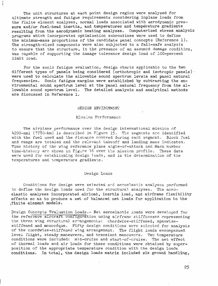
The a i rp l ane pe r fo rmance ove r t he des ign i n t e rna t iona l mi s s ion of 4200-nmi (7780-km) i s descr ibed in F igure 1 5 . The segments a r e i d e n t i f i e d with the fuel used and the dis tance covered during each segment . Block fuel and range a re to ta led and the re levant , t akeoff and landing mass indica.ted. Time h i s t o r y o f t h e wing reference plane angle-of-at tack and Mach number t ime-h i s to ry a r e shown i n F i g u r e 1 6 ove r t he mi s s ion p ro f i l e . Th.ese d a t a were used for e s t a b l i s h i n g d e s i g n l o a d s , a n d i n t h e d e t e r m i n a t i o n o f t h e temperatures and temperature gradients .
Design Loads
Condit ions for design were selected and aeroelast ic analyses performed t o d e f i n e t h e d e s i g n l o a d s u s e d f o r t h e s t r u c t u r a l a n a l y s e s . The aero- e l a s t i c a n a l y s e s i n c o r p o r a t e d a i r l o a d , i n e r t i a l o a d , a n d a i r f r a m e f l e x i b i l i t y e f f e c t s so as t o produce a set of balanced n e t l o a d s f o r a p p l i c a t i o n t o t h e , f i n i t e element models.
Design Concepts Evaluation Loads.- N e t ae roe las t ic loads were deve loped for t h e r e f e r e n c e a i r c r a f t c o n f i g u r a t i o n u s i n g a i r f r a m e s t i f f n e s s e s r e p r e s e n t i n g t h e t h r e e wing s t rut tural arrangements: chordwise-s t i f fened, spanwise- s t i f fened and monocdqae. F i f ty des ign cond i t ions were s e l e c t e d f o r a n a l y s i s of the chordwise-s t i f fened wing arrangement. The f l i g h t l o a d s encompassed l e v e l f l i g h t , s t e a d y maneuvers, and t r a n s i e n t maneuvers. Two temperature condi t ions were included: mid-cruise and s tar t -of-cruise . The n e t e f f e c t of thermal loads and a i r loads fo r t hese cond i t ions w e r e obtained by super- p o s i t i o n of t he appropr i a t e t empera tu re cond i t ion w i th t he des ign l oads cond i t ions - . I n t o t a l , t he des ign l oads ma t r ix i nc luded s ix g round hand l ing ,
SEGMENT
@ Ground Maneuver T.O. and Climb to 5000 f t (1526 m)
(1526 m) for 4 min @ Loiter @ 5000 ft
@ Accelerate to
@Climb to Optimum
@ Cruise @ M = 2.62
325 keas (602 km/hr)
Altitude
8 (Hot Day)
6 Decelerate to 325 keas (602 km/hr) and descend to 5000 ft. (1526 m) @ 325 keas (602) km/hr)
@) Loiter @ 5000 f t (1526 in) for 5 min)
BLOCK FUEL
RANGE
SEGMENT FUEL
I bm
17,540
3.91 0
17,741
77,500
21 9,668
1,410
2,506
324,285
T kg
7,900
~ ~ ~~
1,772
790
35.1 50
99,500
643
1,138
SEGMENT DISTANCE
n.mi.
10
0
1
346
3,714
192
0
~-
4,263
AIRCRAFT MASS I
LANDING
PAY LOAD
750,000 Ibm
426,074 Ibm
64,074 Ibm
49,000 Ibm
(340,000 kg)
(192,107 kg)
( 29,000 kg)
( 22,200 kg) 1
Figure 15. Mission Segment Data
km
18.5
0
1.85
640
6,870
355.3
0
7,885.7
;I
-
1 1
26

I
‘14
.12 Ir 3.0
.10
X u E
= 1.0 a
ANGLE OF ATTACK - O W R P
MACH NO.
TIME -MINUTES
Figure 16. Mach Number/Trim Angle-of-Attack Profile
twenty- f ive pos i t ive symmetr ic f l igh t , th ree nega t ive symmetr ic f l igh t , and s ix teen asymmetr ic f l igh t condi t ions . The des ign cond i t ions a r e d i sp l ayed on the design a i rspeed envelope on Figure 17.
The des ign loading condi t ions for ana lys i s o f the spanwise-s t i f fened and monocoque arrangements did not include the ground handl ing condi t ions, loading a t nega t ive load fac tors , o r the asymmetr ic f l igh t loads . These condi t ions were determined t o be non-cr i t ica l as the r e su l r . o f t he i n t e rna l l oads eva lua - t i on o f t he cho rdwise - s t i f f ened des ign .
Engineer ing Design-Analysis Loads.- Aeroelast ic loads were calculated for the f i n a l d e s i g n a i r p l a n e u s i n g t h e a i r p l a n e c o n f i g u r a t i o n shown in F igu re 2 . The d e s i g n l o a d c o n d i t i o n s a r e i d e n t i f i e d i n Table 3. These condi t ions were se l ec t ed fo l lowing t he r ev iew of t h e d e s i g n c o n c e p t s e v a l u a t i o n r e s u l t s . Figure 18 disp lays these condi t ions super imposed on the des ign a i r speed envelope.
The loading conditions included eight subsonic symmetric maneuvers ( s t eady and t r ans i en t ) ; seven low supersonic conditions, including negative l o a d f a c t o r , and s t eady and t r a n s i e n t maneuvers a t heavy and l ight masses; fou r Mach 2.7 condi t ions , inc luding mid-cru ise l eve l f l i g h t and steady maneuver, and s t eady and t r ans i en t maneuver s a t s t a r t -o f - c ru i se ; two pseudo dynamic gus t condi t ions a t Mach 0.90 ( p o s i t i v e and n e g a t i v e ) ; and four dynamic landing conditions.

VELOCITY - keas I 1 I I I I 0 200 400 600 800 1Mx)
VELOCITY - km/h
Figure 17. Design Loading Conditions - Design Concepts Evaluation
26
20
15 E
w
3 n t 5 a 5 10 W
v) v) w U a
5
0 0 100 200 300 400 500 600
VELOCITY-keas
I I I I I 0 250 500 750 1000
VELOCITY-km/h
Figure 18. Design Loading Conditions - Engineering Design-Analysis

TABLE 3. DESIGN LOADING CONDITIONS DATA
" .
NASTRAN COND.
NO.
1
2
3
4. 5
6. 7
8. 9
10.11
12. 13
14
15, 16
17. 18
19. 20
21.22
23. 24
25. 28
MACH NO. 1- 000 Ib 1000 kg
I
745
700
700
700
690
690
690
445
660
550
700
430
338
318
318
318
31 3
313
31 3
202
299
249
318
195
..
TEMPERATUR
0.40 0.0
0.90
1.25
48.0 1.25
48.0 1.25
22.0 0.90
30.0 0.90
36.0
30.0 0.90
64.0 2.70
61.5 2.70
34.0 1.25
38.2
~~ ~. -.
- I O'O I
CONDl
0.0
10.97
9.14
6.71
14.63
14.63
11x3
10.36
18.74
19.51
9.14
S ? E R
AIRSPEED
0.0 1
IT1 ONS
"
2.5
2.5
2.5
2.5
2.5
.1.0
2.5
2.5
2.5
1 .O, 2.5
-
264.6
282.4
325.0
390.0
294.3
294.3
372.0
420.0
460.0
433.6
325.0
1oo.c
~~ ~
490
523
602
722
545
545
689
778
852
803
602
185
..
REMARKS -
M2.7. START OF CRUISE
M2.7. M I D C R U I S E
M1.25 DESCENT
STRENGTH DESIGN
STRENGTH DESIGN
STRENGTH DESIGN
STRENGTH DESIGN
STRENGTH DESIGN
NEGATIVE FLIGHT
STRENGTH DESIGN
DESCENT -THERMAL
START OF CRUISE
MID CRUISE
PSUEDO - GUST (POSITIVE AND NEGATIVE)
DYNAMIC LANDING CONDITIONS
Design Temperatures
Time histories of structural temperatures for the Mach 2.7 cruise flight profile were calculated using the representative thermal analyzer network models. These models were used to define the temperatures and gradients at the selected wing and fuselage point design regions for the detailed stress analyses, and to d.efine the average temperatures for input into the finite element analysis models. Figure 19 presents the resultant isotherm map for the Mach 2.62 Hot Day cruise condition.
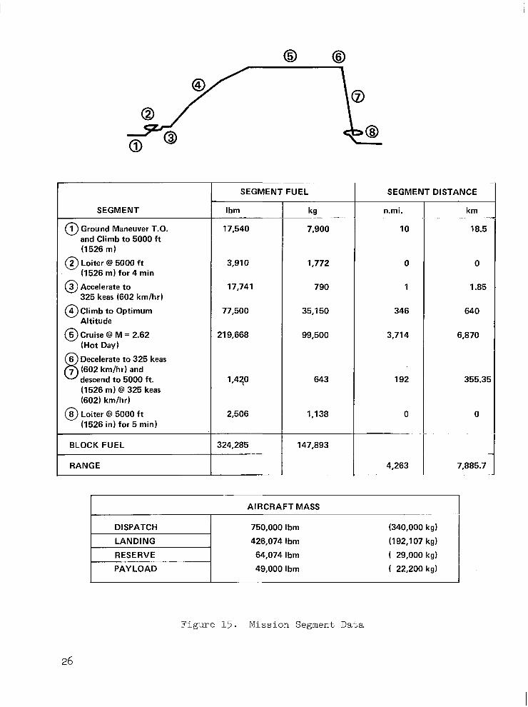
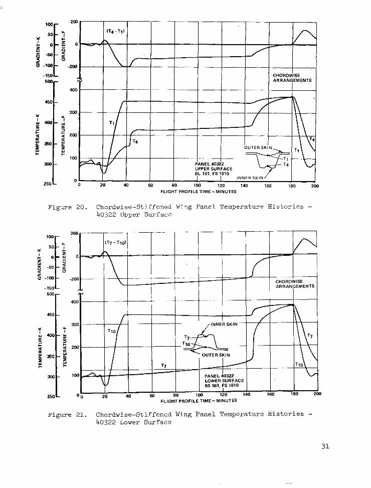
Wing Panel Temperatures.- Representative temperature histories for upper and lower surface wing at point design panels region 40322 are presented for the chordwise-stiffened arrangements in Figures 20 and 21. The temperature gradients reach peak values near the start of cruise and during transonic descent. The panels are located in a fuel tank area and the temperatwe difference across the panel maintains a high value until the fuel is drained from the tank.
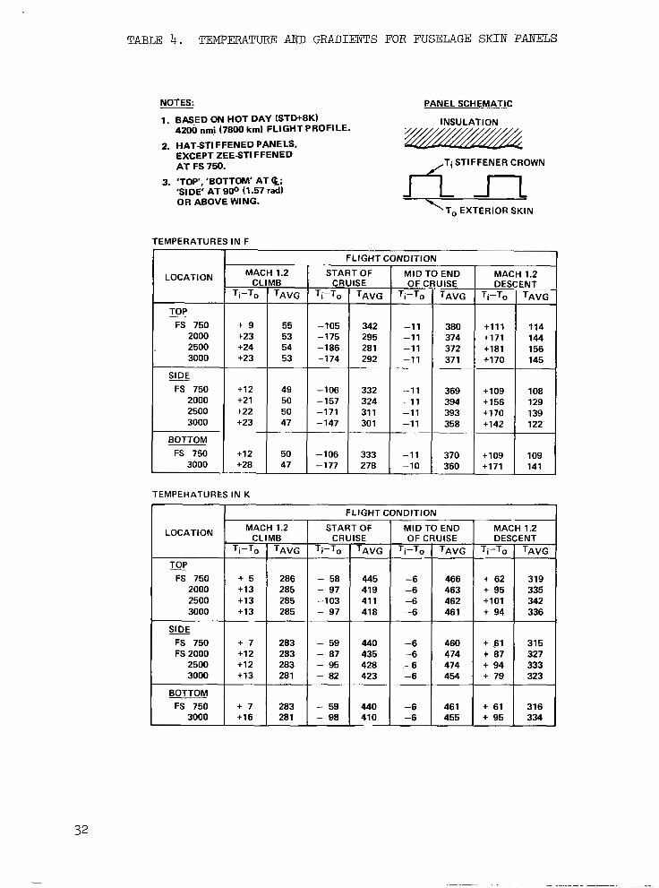
Fuselage Panel and Frame Temperatures.- Temperature histories developed for f u s e l r i a c i r c u m f e r e n t i a l frames are presented in Tables 4 and 5 for ten fuselage locations at four flight conditions: Mach 1.2 climb, start-of-cruise, mid-cruise, and Mach 1.2 descent. Table 4 shows mass-
, averaged temperatures for skin panels and temperature differentials between outer skin and stiffener crown. Table 5 shows mass-averaged frame tempera- tures and differentials between outer and inner flanges of the frame.

w 0
MACH 2.62CRUlSE
HOT DAY (STD + 8K TOTAL TEMPERATURE 535 K (504 F) TEMPERATURE IN K ( .FI
ALTITUDE 21 000 m (69 000 ft )
BASED ON:
0 FINAL CONFIGURATION
TIME = 100 MINUTES (MID-CRUISE) IN 4200 nmi (7800 km) INTERNATIONAL FLIGHT PROFILE
0 ALL SURFACES PAINTED
0 INCLUDE FUEL, MLG COOLING EFFECTS
UPPER SURFACE
LOWER SURFACE
I
Figure 19. External Surface Isotherm - Mach 2.62 (Hot Day) Cruise
-
ISE EMENTS
\ - 0 '
FLIGHT PROFILE TIME- MINUTES
Y
-50
u -100
-150
0
Figure 21. Chordwise-Stiffened Wing Panel Temperature Histories - 40322 Lower Surface
31
TABLF 4. TEMPERATURE AND GRADIENTS FOR FUSELAGE S K I N PANELS
NOTES: PANEL SCHEMATIC
1. BAsED ON HOT DAY (STWBK)
2. HATSTIFFENED PANELS,
4200 nmi (7800 km) FLIGHT PROFILE. INSULATION
EXCEPT ZEESTIFFENED AT FS 750.
3. 'TOP', 'BOTTOM' AT a; 'SI DE' AT 900 (1.57 rad) OR ABOVE WING.
,Ti STIFFENER CROWN
'To EXTERIOR SKIN
TEMPERATURES IN F
T FLIGHT CONDITION r T T T 1.2 1B TAVG
MID TO END MACH 1.2 STAI CR -
Ti-T,
MAC CL
Ti-To
+ 9 +23 +24 +23
r OF SE TAVG
LOCATION
TOP FS 750
2000 2500 3000
SlDE FS 750
2000 2500 3000
BOTTOM FS 750
3000
OF C Ti-To
JlSE TAVG
380 374 372 37 1
369 394 393 358 -~
370 360
DEI Ti-To
INT ~
TAVG
-105 -175 -186 -174
+111 +171 +181 +170
114 1 4 4 156 145
55 53 54 53
49 50 50 47
50 47
342 295 28 1 292
332 324 31 1 30 1
~
333 278
-1 1 -11 -11 -11
-1 1 -1 1 -1 1 -1 1
-11 -10
+12 +21 +22 +23
-106 -157 -171 -147 "
-106 -177
+lo9 +156 +170 +142
108 129 139 122
+12 +28
+lo9 +171
109 141
TEMPERATURES IN K
1 FLIGHT CONDITION
MACH 1.2 START OF CRUISE
Ti-To I TAVG
LOCATION
~
281
TOP FS 750
+13 3000 +13 2500 +13 2000 + 5
S E FS 750 FS 2000
+ 7
+13 3000 +12 2500 +12
BOTTOM FS 750
3000 + 7 +16
-6 466 + 62 319 -6 463 + 95 335 -6 462 +lo1 342 -6 461 + 94 336
-6 460 + 61 315 -6 474 + 87 327 -6 474 + 94 333 -6 454 + 79 323
-6 461 + 61 316 -6 455 + 95 334
- 59 - 87
- 82
- 59 - 98

TABLE 5. TEMPERATURE AND GRADIENTS FOR FUSELAGE FRAMES
NOTES:
1. BASED ON HOT DAY (STD + 8K) 4200 nmi (7800 km) FLIGHT PROFILE
2. 'TOP','BOTTOM' AT Q; 'SIDE' AT 900 (1.57 rad) OR ABOVE WING.
3. INSULATION ASSUMED A T FS 3OW (AFT OF PRESSURE BULKHEAD)
/ Ti INNER FLANGE
T, OUTER' FLANGE
TEMPERATURES I N F
LOCATION
TOP FS 750
2000 2500 3000
=E FS 750
2000 2500 3000
BOTTOM FS 750
3000
FLIGHT CONDITION MACH 1.2 I STARTOF I MIDTO END I MACH 1.2
+11
-76 274 -160 114 - 73 74 + 6 -72 274 -148 109 - 63 74 + 5 -76 276 -161 115 - 74 74 + 6 -56 277 -186 145 -133 73
"
202 233 242 232
+14 + 8 + 7 + 9
+13 226 -76 265 -154 108 - 63 73 + 8 196 -53 270 -180 140 -126 72
TEMPERATURES IN K
I I FLIGHT CONDITION
LOCATION
TOP FS 750
2000 2500 3000
S B FS 750
2000 2500 3000
BOTTOM FS 750
3000
MACH 1.2 1 STARTOF I MID TO END I MACH 1.2
+6 296 -74 336 +3 296 -41 319 +3 296 -35 316 +3 296 -41 319
+8 295 -70 333 +4 296 -50 323 +4 296 -42 319 +5 295 -44 319 -~
+7 295 -70 333 +4 296 -35 315
-103 409 -31 - 89 409 -42 - 82 .408 -40 - 89 408 -42
- 99 405 -29 - 95 417 -37 - 88 417 -36 - 84 403 -34
-100 405 -29 - 86 403 -42
368 385 390 384
364 388 393 376
364 381
Fuel Tank Temperatures.- The des ign o f t he fue l s to rage and t he rma l p ro t ec t ion systems ref lected maintenance of hea t sink capab i l i t y , min imiza t ion o f fuel ' v a p o r i z a t i o n ( b o i l o f f ) , r e t a r d a t i o n o f r e s i d u e f o r m a t i o n s , i n h i b i t i o n of thermochemica l reac t iox of fue l vapor in ho t t anks , and main tenance of t ank s e a l a n t i n t e g r i t y . The design concepts accounted for the above by adopt ing as a r e fe rence fue l sys tem the fue l sys tem concepts deve loped and tes ted for : (1) the proposed L-2000 supe r son ic t r anspor t and ( 2 ) t h e YF-12 series super- s o n i c a i r c r a f t .
F u e l h e a t s i n k c a p a b i l i t y was de termined by the d i f fe rence be tween the fue l t empera tu re l i m i t a t the engine and bulk fue l t e m p e r a t u r e i n t h e f e e d tanks . This capa .b i l i ty vas opt imized by using fuel p lacement and schedul ing similar t o t h e r e f e r e n c e s y s t e m . For t h e r e f e r e n c e f u e l s y s t e m , s a t i s f a c t o r y coo l ing capac i ty was maintainable even under severe operat ing condi t ions and wi th a lOOF (311K) fue l supply t empera ture . This was accomplished without i . n s u l a t i n g t h e t a n k s o r p rov id ing ac t ive coo l ing .
Bulk f u e l t e m p e r a t u r e h i s t o r i e s f o r t h e wing t anks are shown i n F i g - ure 22. Temperatures are shown for each sec t ioned tank f rom s tar t a t 7OF (294K) u n t i l t h e t a n k f u e l leve l has d ropped to two-percent o f the o r ig ina l value (assumed usable l i m i t ) . T h i s f u e l was pumped t o t h e c o o l f u s e l a g e . tanks before subsequent use. The wing tank temperatures wer? s i g r , i f i c a n t l y be low boi l ing t empera ture and inh ib i ted fue l evapora t ion whi le fue l w a s being drawn from each tank .
The r e s u l t s o f t e s t s c o n d u c t e d on the r e f e rence fue l sys t em, p lus observa t ion of YF-12 se r i . e s a i r c ra f t fue l t anks (n i t rogen-purged) sub jec t ed t o h i g h e r t e m p e r a t u r e s , i n d i c a t e t h a t a n i t rogen purge jpressur iza t ion sys tem sa t i . s fy ing r equ i r emen t s fo r fue l t ank i ne r t ing p rov ided e f f ec t ive i nh ib i t i on of vapor react ion and res idue formation.
Experience with YF-12 s e r i e s a i r c r a f t i n d i c a t e t h a t c u r r e n t f u e l t a n k s e a l a n t s r e t a i n e f f e c t i v e n e s s up to t empera tu res o f a t l e a s t 44OF ( 5 0 0 ~ ) . In e l imina t ing t he r equ i r emen t fo r fue l t ank i n su la t ion , t he fue l sys t em des ign a s su res ea sy access and maintenance when tank sea l .an ts must be r e p a i r e d or rep laced . The .probler r . o f fue l absorp t ion in porous insu la t ions i n t h e e v e n t o f s l i g h t s e e p a g e was a l s o e l i m i n a t e d .
Acoust ics
The acous t i c env i ronmen t wh ich t he a i r c ra f t would be subjected t o d u r i n g t akeof f w a s es t imated f rom empir ica l f ree- f ie ld acous t ic l eve ls genera ted by an zxis t ing turbojet engine. Adjustments were then made t o a c c o u n t f o r t h e d i f f e r e n c e i n t h e g e o m e t r i c c h a r a c t e r i s t i c s o f t h e t u r b o f a n e n g i n e s , t h e operat ing parameters , the ambient environment , and the presence of s t ructure w i t h i n t h e a c o u s t i c f i e l d .
I so in tens i ty Contours . - The o v e r a l l sound p r e s s u r e l e v e l s (OASPL) were determined using the reference contours of Figure 23 and t h e c a l c u l a t e d incrementa l changes assoc ia ted wi th the base l ine des ign . F igure 24 d i s - p l a y s t h e i s o i n t e n s i t y c o n t o u r s f o r t h e b a s e l i n e e n g i n e l o c a t i o n .
34

400 - 250
380 - 200
360 - Y 1
3 E 340 - 5 150 I- I-
K 0" 320 - I- t-
300 -
U
w 1 w
a a a
5 5 100
280 - 50
260
FLIGHT PROFILE TIME - MINUTES
Figure 22. Bulk Fuel Temperatures in Wing Tanks
0
$ 5
g 10
L 5
u- N -I
N
7
15
w 0 z a t; 20 n
n s a a 25
- -I
30 -15 -10 -5 0 5 10 15 20 25 30
AXIAL DISTANCE FROM JET NOZZLE, X/D
Figure 23. Near-Field Noise Contours - Reference Turbojet Engine
35


TABLE 6 . WING PANEL LOAD/TEMPERATURE ELVIRONMENT - INITIAL SCREENING MASS = 690 X 103 LW
CHORDWISE
ARRANGEMENT
SPANWISE STIFFENED
ARRANGEMENT STIFFENED
UPPER
""l ARRANGEMENT
LOWER UPPER LOWER
MONOCOQUE
ULTIMATE DESIGN LOADS ITEM
Ibflin. 1 1,424 -1 1,424 16,986 -16,986 14.325 -14,325 Ibflin. NY AIR LOADS 3.171 -3,171 -306 306 1,305 -1,305 Ibflin.
SURFACE SURFACE SURFACE SURFACE SURFACE SURFACE UNITS UPPER LOWER
" - !x
NXY 2,358
-8.29 -6.34 -10.14 -8.96 -8.29 4.94 psi NET 4.03 -5.67 -8.94 -5.93 -8.03 -5.67 Psi FUEL
..26 -1.27 -1.20 -3.03 -.26 I .1.27 Pi AERO
0 0 0 0 0 0 in.lin. CXY
0 0 0 0 0 0 in./in. C Y
0 0 0 0 0 0 in.lin. E X
4,847 4,847 2,541 2.54 1 2,354
OF 147 136 139 139 147 148 A T -115 -127 -130 -138 -131 -136
THERMAL STRAIN
PRESSURE
TEMPERATURE TAV
MASS = 313 X 103 Kg CHORDWISE
STIFFENED STIFFENED SPANWISE
ARRANGEMENT ARRANGEMENT ARRANGEMENT MONOCOQUE
ULTIMATE UPPER LOWER UPPER LOW E R UPPER LOWER DESIGN LOADS
2,000 j -2,000 2.975 -2,975 2,508 -2,508 kNlm NY AIR LOADS
, SURFACE SURFACE SURFACE SURFACE SURFACE SUfiFACE UNITS ITEM
N x 555 -555 -54 54 228 -228 kNlm
N x y kNlm
0 0 0 0 0 0 m/m €XY
0 0 0 0 0 0 m/m E Y
0 0 0 0 0 0 m/m E X
849 a49 445 445 412 412
THERMAL STRAIN
AERO -1.79 -8.76 8.27 -20.88 -1.79 -8.76 kPa
NET kPs
-77 -73 -75 -72 -7 1 -64 338 337 333 333 331 337 OK
-57.15 47.85 89.87 -61.76 -57.15 -47.85 PRESSURE -55.36 1 -39.09 61.60 40.88 -55.36 -39.09 kPa FUEL
TEMPERATURE aT TAV
O K
' NOTES 11) A 1.25 FACTOR HAS BEEN APPLIED TO THE THERMAL STRAIN WHEN THE SIGN IS SAME AS AIRLOAD SIGN
12) PRESSURE SI CONVENTION: NEGATIVE - SUCTION 131 CONDITION 8 ; MACH NO. - 1.25; nZ - 2 5 14) POINT DESIGN REGION 40536
OTHERWISE NO FACTOR APPLIED.
TABLE 7. FUSELAGE PANEL LOAD INTENSITIES - INITIAL SCREENING
LOCATION
UPPER PANEL
SIDE PANEL
LOWER PANEL
T FUSELAGE PANEL LOAD INTENSITIES (ULT.)
t FS 2000, FS 3000 T
XXXX = Ibf/in:
I DIRECTION 1- U
Nx I -1 1700 (-2049)
__ n 1 1700 (2049)
417 (73)
406 (71)
1357 (238)
-11650 [ -2040)
412 (72)
- -L
11600 (2031)
413 (72)
300 ( 52)
1330 (233)
- 1 2000 (-2100)
426 (75)
T - U
15700 (2749)
629 (1 10)
422 (74)
2025 (355)
-16100 [ -2819)
645 (1 13)
14600 15690 (2557) (2748)
597 629 (104) (110)
545 416 (95) (73)
2000 1998 (350) (350)
-1 6800 15900 -2942) ( -2784)
670 633 (1171 (111)
1 1
Chordwise-Stiffened Wing Concepts.-The panel structural mass data of Figure 25 compares the mass efficiency of the four candidate designs at the selected point design regions. The surface panel mass (upper and lower) is presented as a function of a variable spar spacing. The results show that the convex-beaded concept which employs structurally efficient circular- arc elements was minimum-mass at all design regio.ns .for the spar spacings investigated.
Spanwise-Stiffened Wing Concepts.-Comparative data of surface panel mass for the spanwise-stiffened concepts are presented in Figure 26. Graphical display of the sum of the upper and lower surface panel mass is shown as a function of rib spacing. The data show that the minimum-mass panel con- cept was the hat-stiffened design at all point design regions and rib spacings investigated, with one exception. At region 40536 for the 20-in (0.51-111) rib spacing, the most mass-efficient design was the zee-stiffened concept. The least efficient design was the integral-stiffened design.
Monocoque Wing Concepts.-The biaxially-stiffened panel concepts were sub- jected to the same depth of analysis as the uniaxially stiffened concepts. In addition, prior to screening the two biaxially-stiffened panel concepts, honeycomb sandwich and truss-core, an analysis was conducted to ascertain the panel proportions (aspect ratio) associated with minimum mass design.
The aspect ratio parametric study was conducted using both multispar and multirib honeycomb-core sandwich panel structural box designs. The results of this analysis indicated that the multispar approach affords the most mass-efficient designs considering the panels alone, and considering the complete wing box structure. The inclusion of the substructure in the mass analysis resulted in a larger variation between the multirib and mul- tispar designs and a clearer definition of the minimum mass arrangement.
The comparison of structural mass.trends of the honeycomb sandwich design (brazed) and the truss-core design (diffusion bonded) is presented in Figure 2 7 . The trends shown are for the multispar substructure considering both upper and lower surface panel mass. The data shows that the honeycomb panel concept was the more efficient design at the three design regions investigated . Fuselage Shell Concepts.-A frme spacing study was conducted to define an appropriate spacing for panel screening analysis. This study was performed using two of the candidate shell concepts, zee- and hat-stiffened. Analyses were conducted at point design regions FS 2000, FS 2500, and FS 3000 using their respective environmental design data. Figure 28 presents the results of the study at FS 2500, indicating that the frame spacing between 20- and 25-in (0.51- and Ot64-m) offer minimum mass designs. Review of these data in conjunction with the wing study results, indicated that the lower bound value was the most relistic spacing.
The screening of the three candidate fuselage panel concepts were con- ducted using the results of aforementioned frame spacing study, i.e., 20.0- in (0.51-m) frame spacing. The average panel mass data for the panel con- cepts are shown in Table 8 and indicate the closed-hat panel concept is the minimum-mass design for each point design region with the exception of FS 750, where the zee-stiffened concept is lighter. Average panel mass ranged
39


TABLE 8. MASS TRENDS OF THE CANDIDATE FUSELAGE PANEL CONCEPTS - INITIAL SCREENING
I1 I I POINT I AVERAGE PANEL MASS I
DESIGN REGION
- n U 1 FS 750
(16.36) 3.35 FS 2500 2.98 FS 2000
- - -
(14.55) 2.98 FS 3000
-
A I
\.\.\ 3.01 3.52 3.01 I (14.70) 1
NOTES:
1. CONSTANT FRAME SPACING = 20.0 - in. (.51-m) 2. X.XX = Ibm/ft2; (X.XX) = kg/m2
Detailed Concept Analyses
The most promising s t ructural concepts’ (Figure 29) were sub jec t ed t o fur ther mass-s t rength ana lyses a t an extended set of po in t des ign reg ions ; a t o t a l o f s i x wing and fou r fu se l age r eg ions . In add i t ion , t he app l i ca - t ion o f composi te material re inforcement to p r imary s t ruc ture w a s i n v e s t i - g a t e d t o e v a l u a t e p o t e n t i a l mass s a v i n g b e n e f i t s .
The panel concepts were combined w i t h t h e i r a s s o c i a t e d s u b s t r u c t u r e s t o form r e p r e s e n t a t i v e wing box and fuse l age she l l s t ruc tu res . In -dep th structural analyses were con,ducted on each u n i t s t r u c t u r a l component, i nc lud ing u l t ima te and f a t igue s t r eng th ana lyses , f a i l - s a fe ana lyses , and son ic f a t igue ana1ys . e~ . Es t ima ted t o t a l a i rp l ane mass d a t a f o r e a c h s t ruc tu ra l app roach were obtained by extrapolat ion of t h e u n i t mass d a t a of the point design regions over the remainder of t h e a i r c r a f t .
V ib ra t ion and f l u t t e r ana lyses , and f l u t t e r o p t i m i z a t i o n s t u d i e s w e r e conducted using the f ini te e lement models represent ing each of the s t ruc- tu ra l a r rangements , i . e . , chordwise-s t i f fened , spanwise-s t i f fened and monocoque, t o de t e rmine t he add i t iona l s t i f fnes s and mass needed t o meet t h e f l u t t e r s p e e d r e q u i r e m e n t s .
Product ion cos ts were a l so deve loped for each of the wing concepts u s ing t he common skin-s t r inger-frame fuselage design. These costs were der ived by e v a l u a t i n g t h e f a b r i c a t i o n and assembly ope ra t ion fo r each design on a p o i n t d e s i g n b a s i s a n d e x t r a p o l a t i n g t h e s e r e s u l t s t o encompass the overa l l wing .
42

STRUCTURAL ARRANGEMENT
CHORDWISE - STIFFENED WING
SPANWISE - STIFFENED WING
MONOCOQUE WING
FUSELAGE - SKIN/STRINGER
" ~. -
PANEL CONCEPT
CIRCULAR-ARC/CONVEX BEADED SKIN
HAT STIFFENED SKIN
HONEYCOMB SANDWICH - ALUMINUM BRAZED
CLOSED HAT STRINGERS
GEOMETRY ~-
Figure 29. Promising Structural Concepts
Strength-Design Analyses.-The results of the wing and fuselage detailed concept analyses, with the exception of the sonic fatigue analyses, are discussed in the following text. The sonic fatigue analyses indicated positive margins-of-safety for all designs; thus, the acoustic environment did not impact the selection process and the results of these analyses are not included.
The critical flight conditions and corresponding overall wing internal load and temperature distributions remained unchanged between these analyses and the prior initial screening analyses. The fuselage point design loads and temperatures are shown in Table 9 and reflect the internal loads, cabin pressure and temperature data for the start-of-cruise flight condition.
Chordwise-Stiffened Wing Arrangement: An example of the detailed mass- strength analysis results is presented in Figure 30 to indicate the magni- tude of the strength-sizing effort conducted on, not only the chordwise- stiffened wing, but also the spanwise-stiffened and monocoque wing designs. The data present the component and total wing box mass at point design region 40536 as a function of a variable spar spacing. The components included in this investigation were the upper and lower surface panels (convex-beaded construction), spar-caps and webs, rib-caps and webs, and appropriate non-optimum struc'ture.
Figure 31 displays the wing box mass resulting from the above mass- strength analyses f o r each of the six point design regions. The minimum mass designs at each of the regions occur at a spar spacing of 20-in (0.51-m), with the wing box mass varying from 3.79-1bm/ft2 (18.50-kg/m2) at region 40322 (forward box) to 15.54-lbm/ft2 (75.87-kg/m2) at region 41316 (wing tip).
43


To assess t h e damage to l e rance o f t he s t r eng th - s i zed chordwise - s t i f f ened des igns , bo th su r f ace pane l s and spa r s were s u b j e c t e d t o a fail- safe eva lua t ion . For the sur face pane ls , a damage condi t ion o f a th ree - s t r i n g e r p i t c h o u t e r s k i n c r a c k w i t h two b roken r e in fo rc ing s t i f f ene r s ( inne r bead ) was s e l e c t e d . Depending upon t h e l o c a l g e o m e t r y , t h i s r e s u l t e d in c r ack s i ze s be tween 5 - in (0.13-m) t o 13-in (0.33-m). A r e s i d u a l s t r e n g t h a n a l y s i s w a s conducted and ver i f ied the fail-safe c a p a b i l i t y o f t he s t rength-design. Therefore , no mass p e n a l t y w a s a s s e s s e d t o t h e chordwise-s t i f fened panel concepts .
A broken spar cap damage cond i t ion w a s ana lyzed s ince in the chordwise- a r rangement the spar caps car ry the wing spanwise bending loads. To assess t h i s damage c o n d i t i o n , t h e s p a r c a p was assumed t o be completely broken and t h e a d j a c e n t s t r u c t u r e a n a l y z e d f o r t h e r e d i s t r i b u t e d l o a d s . The s t r eng th - designed components for three spar spacings were evaluated a t each point de- s ign r eg ion . The mass p e n a l t i e s a s s o c i a t e d w i t h e a c h s t r u c t u r a l component of t h e wing box are shown in F igu re 32 fo r po in t des ign r eg ion 40536. The r e s u l t a n t mass p e n a l t i e s f o r t h e t h r e e p o i n t d e s i g n r e g i o n s f o r t h e damaged spar cap condi t ion are p resen ted i n Tab le 10 .
Spanwise-Stiffened Wing Arrangement: Ul t imate and fa t igue s t rength analyses were conducted on the spanwise-stiffened wing box structure using t h e minimum-mass ha t - s t i f f ened pane l concep t . The wing box u n i t mass a t each o f t he s ix po in t des igns i s shown in Figure 33. Region 40536, which is l oca t ed a t app rox ima te ly t he mid span of t h e wing a f t box, y i e l d s a minimum mass design of 13.58-lbm/ft2 (66.3-kg/m2) for a 30-in (0.76-m) r i b spacing. The u n i t mass a t r eg ion 40322 was 4.71-lbm/ft2 (23-kg/m2) for a 20-in (0.51-m) r i b s p a c i n g .
14
12 N E
10 Y
I
Z 8 -I
a t 6 2 4 m n
5
2
0
"
1 - 1
CHORDWISE ARRANGEMENT CONVEX - BEADED PANEL
1 1 I
r DESIGN REGION 40536 I I
TOTAL
SPAR WEB
PAN E LS
40 SPAR SPACING - in
I I .50 .75 1 .oo
SPAR SPACING - m
Figure 32. Component Mass P e n a l t i e s f o r a Damaged Spar Cap - Chordwise-Stiffened Arrangement
46
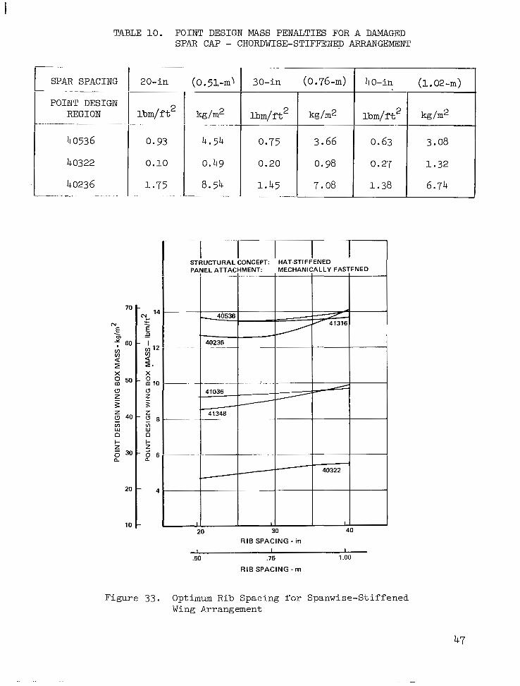
TABLE 10. P O I N T D E S I G N MASS P E N A L T I E S F O R A DAMAGED SPAR CAP - C H O R D W I S E - S T I F F E W ARRANGEMENT
I REGION 1 l b m / f t 2 I I ~ -
P O I N T D E S I G N
40536 0.93
40322 0.10
40236 1.75 "-. . I
70
N . E
60 IJ)
v)
9 z X
50
u z 3
40 0) w 0 I- 5 30 n
20
10
30-in ( 0 . 7 6 - m ) I 40-in (1.02-m)
l b m / f t 2 kg/m2 l b m / f t 2
0.75
1.32 0.27 0.98 0.20
3.08 0.63 3.66
I 1 STRUCTURAL CONCEPT: ' HAT-STIFFENED
RIB SPACING - in I I I
.50 .75 1 .oo RIB SPACING - r n
Figure 33. Optimum Rib Spacing for Spanwise-Stiffened Wing Arrangement
47


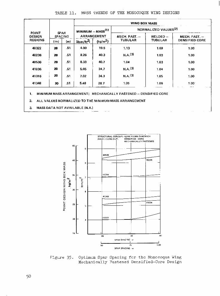
TABLE 11. MASS TRENDS OF THE MONOCOQUE WING DESIGNS
POINT DESIGN REGIONS
40322
40236
40536
41036
41 31 6
41 348
SPAR SPACING
.51
.51
i WING BOX MASS
MINIMUM MASS(^) VALUES(~)
ARRAh
(Ibrnltt2)-
4.00
8.26
8.33
5.05
7.02
5.49
EMENT
( k d m 2 )
19.5
40.3
40.7
24.7
34.3
26.7 . ~~
MECH. FAST. - TUBULAR
1.13
N.A.(3)
1.04
N.A.(3)
N.A.(3)
1.05
1.09
1.03
1.03
1.04
1.05
1.06 ~.
WELDED - TUBULAR DENSIFIED CORE
MECH. FAST. -
~
1. MINIMUM MASS ARRANGEMENT: MECHANICALLY FASTENED - DENSIFIED CORE
2. ALL VALUES NORMALIZED TO THE MINIMUM-MASS ARRANGEMENT
3. MASS DATA NOT AVAILABLE (N.A.)
1 .oo
1.00
1 .oo
1 .oo
1 .oo
1.00. ~- "
45 - 9
VI 40 -
8
2
g 35
z >
-
3 z.
I?
I X
"E N,
E .n
c . 30 -
VI W 0
Z_ 2 5 - F
0 a
20 -
15 - 20 30 40
SPAR SPACING . m
I I J 50 .75 1 .oo
SPAR SPACING m
Figure 35. Optimum Spar Spacing for the Monocoque Wing Mechanically Fastened Densified-Core Design

1.51) 20.0
I X X . X I = rn X X . X = In
DAMAGE CONDIT ION:
0 BROKEN INSERT OR STRAP 0 2 BAY SKIN CRACK IUPPER A N D LOWER SKINS)
Figure 36. Monocoque Panel Damage Configurat ions
For the p redominant ly p ressure- loaded sur face pane ls the material systems considered for re inforcement were (1) MODMOR II/Skybond 703 graph i t e - polyimide, ( 2 ) Boron/Skybond 703 boron-polyimide, and ( 3 ) 5.6 boron/1100 aluminum wi th t i t an ium in t e r l eaves . The surface-panel mass d a t a f o r r e g i o n 40536 are d i sp layed i n F igu re 37 f o r t h e c a n d i d a t e m a t e r i a l s y s t e m s . The da ta i nd ica t e t ha t t he g raph i t e -po ly imide r e in fo rced su r f ace pane l i s t h e least-mass. composite approach. It should be noted, however, that the metal- l i c convex-beaded panel concept mass i s approximately 8-percen-t l i g h t e r t h a n t h e minimum mass graphite-polyimide composite reinforced design.
The component e x h i b i t i n g t h e g r e a t . e s t p o t e n t i a l mass saving was t h e submerged spar cap of the chordwise-s t i f fened arrangement which account for approx ima te ly 60 -pe rcen t o f t he t o t a l box mass at reg ion 40536. To eva lua te t h e mass-saving potent ia l , boron-polyimide was s e l e c t e d as the re inforcement material system t o b e a p p l i e d u n i d i r e c t i o n a l l y t o t h e t i t a n i u m a l l o y 6A1-4V spar caps. The c o m p r e s s i v e s t r e s s e f f i c i e n c y , t h e r m a l s t r a i n c o m p a t i b i l i t y w i th t i t an ium, and t e n s i l e s t r a i n c o n s t r a i n t d i c t a t e d by t h e g r o s s area t e n - s ion stress cu to f f of 90,000-psi (619-MPa) f o r t h e t i tanium a l l o y , were de- c i s ive f ac to r s i n t he s e l ec t ion o f t he bo ron-po ly imide material system over '
t he g raph i t e -po ly imide sys t em se l ec t ed fo r t he su r f ace pane l des ign .
The r e s u l t s o f t h e above inves t iga t ions were a p p l i e d t o two d i f f e r e n t wing box des igns . The f i r s t design used Gr/PI reinforced panels and B/PI spar caps . The second design-employed an a l l metal des ign wi th on ly the spar caps employing composite reinforcement (B/PI). A comparison of wing box mass for t h e s e two arrangements with the least-mass metal l ic arrangement i s shown i n F i g u r e 38. Both composite designs offer a mass reduc t ion of approximately 35 percent over the a l l me ta l l i c des igns fo r comparab le spa r spac ings .
Table 12 summarizes the composi te re inforced wing-box mass d a t a f o r each of the wing d e s i g n r e g i o n s . I n c l u d F d i n t h i s t a b l e a r e t h e component mass of the chordwise-s t i f fened beaded panel design and the mass e s t ima te for the composi te re inforced spar caps . The mass savings for the composi te r e i n f o r c e d d e s i g n i n t h e h i g h l y l o a d e d wing r eg ion 40536 when compared wi th
51
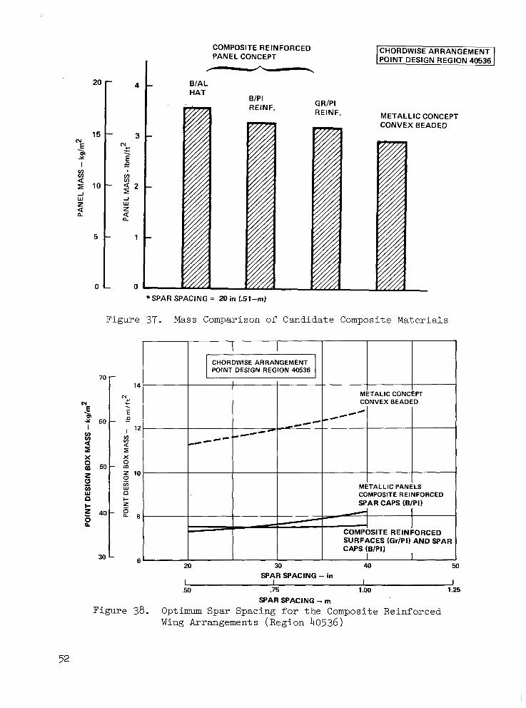
20 - 4
N 15 - 3
E m
E I f!
. 9
’’, Y
. w-
v) v)
5 1 0 - 1 2 -I W z W
n
J
n z a a
5 - 1
0 - 0
COMPOSITE REINFORCED PANEL CONCEPT -
BIAL HAT
CHORDWISE ARRANGEMENT POINT DESIGN REGION 40536
SPAR SPACING = 20 in (.51-m)
Figure 37. Mass Comparison of Candidate Composite Materials
70 - 14
METALIC CONCEPT N
cuw r
E CONVEX BEADED
E 2 6 0 - -p
I v)
1 D
. (0)
I ’ 2
a *cc”‘c
”4H”
v) ”- *
v)
X X
5 0 -
I
z z 10 L?
v) w W
0
METALLIC PANELS
c
P v)
D I-
COMPOSITE REINFORCED
z SPAR CAPS (B/PI) - 40-
2 I 2
SITE REINFORCED SURFACES (Gr/PI) AND SPAR CAPS (B/PIJ
30 - fi I I - 1 20 30 40 50
I I I I .50 .75 1 .oo 1.25
SPAR SPACING - in
SPAR SPACING - m Figure 38. Optimum Spar Spacing f o r t h e Composite Reinforced
Wing Arrangements (Region 40536)

TABLE 1 2 . DETAILED WING BOX MASS FOR BEADED PANELS WITH COMPOSITE REINFORCED SPAR CAPS
I I POINT DESIGN ! I '7
REGION 40322 40236 40536 41036 I 41316 i 41348 I ,
SPAR SPAC (IN I 20 20 20 20 20 20
PANELS
UPPER 0.825 1.032 1.609 1.452 2.571 1.632 LOWER 0.942 1.279 1.335 1.320 2.007 ' 1.366
c (1.767) (2.311) (2.944) (2.772) (4.578) (2.998)
RIB WEBS
BULKHEAD 0.298 0.279 0.238 0.111 0.270 0.106 TRUSS - -
c 0.074 0.237 0.228 0.060
(0.372) (0.5161 (0.466) (0.171) (0.270) (0.1061 ,
SPAR WEBS i BULKHEAD 0.336 0.361 0.270 0.109 , 0.439 0.291 TRUSS 0.301 0.544 0.490 0.359 - -
c (0.637) (0.905) (0.760) 10.468) (0.439) (0.291)
RIB CAPS
UPPER 0.058 0.070 0.116 0.093 0.160 0.103 LOWER 0.065 0.083 0.086 0.087 0.126 0.074
(0.123) (0.153) (0.202) (0.1801 (0.2861 (0.177) c SPAR CAPS
UPPER 0.241 1.240 1.140 0.900 1.440 1.060 LOWER 0.350 1.740 1.530 1.120 2.050 1.380
j (0.591) (2.980) 12.670) (2.020) (3.4901 (2.440) c !
~ 0.200 ~
6.330
~ NON-OPTIMUM I I I
~ ~ MECH. FAST. , ~ 0.180 ~ 0,200 0.200 WEB INTERS. 0.120 0.120 0.120
(0.300) (0.320) (0.320)
I IDESlGNI 3 I 3.790 I 7.180 i 7.360 POINT LBM
MASS
0.200 0.120
(0.3201
I 0.200 , 0,120
9.380
POINT DESIGN REGION 40322 40236 40536 41036 41316 41348
SPAR SPAC (ml 0.508 0.508 0.508 0.508 0.508 0.508
PANELS
UPPER LOWER
c 4.028 5.039 7.856 7.090 12.553 7.968 4.599 6.245 6.518 6.445 9.799 6.670
(8.627) (11.284) (14.374) (13.535) 122.3521 (14.638)
RIB WEBS
BULKHEAD 1.455 1.362 1.162 0.542 1.318 0.518 TRUSS 0.361 1.157 1.113 0.293 -
I C -
(1.816) (2.519) (2.275) (0.8351 (1.318) (0.518)
SPAR WEBS
1 BULKHEAD 1.640 1.763 1.318 0.532 2.143 (1.421) TRUSS - c 1.470 2.656 2.392 1.753
(3.110) (4.419) (3.710) (2.285) (2.143) (1.421)
-
RIB CAPS
UPPER 0.283 0.342 0.566 0.454 0.781 (0.503)
c LOWER ' 0.317 0.405 0.420 0.425 0.615 (0.361)
' (0.600) (0.747) (0.9861 (0.879) (1.396) (0.864)
SPAR CAPS
UPPER LOWER
1.177 . 6.054 5.566 4.394 , 7.031 5.176 1.709 8.496 1 7.470 5.468 10.009 6.738 ,
(2.886) I (14.550) 1 (13.036) ~ (9.8621 i (17.0401 (11.9141 , c NON-OPTIMUM
MECH. FAST. WEB INTERS.
~~~ ~
0.879 0.586
0.976 0.976 0.976 0.976 0.976
(1.5621 (1.562) (1.562) (1.562) (1.562) (1.465)
0.586 0.586 0.586 0.586 0.586
DESIGN m2 MASS
POINT 30.907 45.799 28.954 35.936 35.057 18.505 ks
the chordwise-s t i f fened , the spanwise-s t i f fened , and the monocoque designs were 3. gg-lbm/ft2 (19. 48-kg/m2) , 6. 38-lbm/ft2 ( 31 .15-kg/m2) and 0. 97-lbm/ft2 (4.74-kg/m2) , r e s p e c t i v e l y .
Composite r e in fo rced spa r caps were s tud ied f rom the po in t o f view of damage t o l e r a n c e p o t e n t i a l f o r t h e m u l t i p l e e l e m e n t c h a r a c t e r i s t i c s of t h e design. The l o a d c a r r i e d i n t h e m e t a l l i c s u b s t r a t e a n d e a c h o f t h e compos- i t e elements, as w e l l as t h e t o t a l l o a d , was c a l c u l a t e d a t t h e s e l e c t e d p o i n t des ign r eg ions fo r t he spa r spac ing boundary va lues , i.e. , 20-in (0.51-m) and 40-in (1.02-m). An except ion was the lower sur face spar caps for 20- in (0.51-m) spac ing a t po in t des ign r eg ion 40322. Composite reinforcement was n o t u s e d i n t h i s r e g i o n d u e t o t h e n e g l i g i b l e mass sav ing i nd ica t ed ove r t he homogenous metal design. The r e s u l t s i n d i c a t e d t h a t a l l composi te re inforced spar caps were damage t o l e r a n t u n d e r t h e c o n d i t i o n o f a s ingle b roken ele- ment. The excep t ion be ing t he s l i gh t ly nega t ive marg in (1 -pe rcen t ) i nd ica t ed f o r t h e s p a r c a p s w i t h 40-in (1.02-m) spacing a t poin t des ign reg ion 40322. No redes ign of these caps was a t t empted s ince t he s t r eng th ana lyses i nd ica t ed t h e smaller spar spac ings , between 20-in (0.51-m) and 30-in (0.76-m), were a l s o c l o s e t o t h e minimum-mass design.
Fuse lage She l l : The most p romis ing fuse lage she l l concepts surv iv ing
eva lua t ion a t the fou r fu se l age po in t des ign r eg ions . These concepts con- s i s t e d o f the closed-hat and zee-s t i f fened designs, wi th the l a t t e r only a p p l i c a b l e t o t h e f u s e l a g e f o r e b o d y , i . e . , FS 750. I n a d d i t i o n , o n l y t h e minimum mass s p a c i n g , 2 0 - i n ( 0 . 5 l - m ) , d e f i n e d i n t h e i n i t i a l s c r e e n i n g a n a l - y s i s was u s e d i n t h e d e t a i l e v a l u a t i o n - o f t h e s e s h e l l c o n c e p t s . The po in t des ign env i ronmen t u sed fo r t h i s i nves t iga t ion i s shown in Tab le 9.
' t h e i n i t i a l s c r e e n i n g a n a l y s i s w e r e s u b j e c t e d t o a n i n d e p t h s t r u c t u r a l
I n a d d i t i o n t o t h e membrane analyses conducted on the . she l1 , d i scon- t inu i ty ana lyses were conducted a t t h e f r a m e / s h e l i i n t e r f a c e t o a s s e s s t h e t o t a l s t r e s s - s t a t e f o r b o t h s h e l l and frame. T y p i c a l r e s u l t s showing t h e c i r cumfe ren t i a l ma te r i a l d i s t r ibu t ion fo r t he ha t - s t i f f ened concep t a t FS 2500 a re d i sp l ayed i n Tab le 13 . Tab le 1 4 summarizes t h e t o t a l e q u i v a - len t th ickness for each po in t des ign reg ion and the cor responding un i t mass da ta . A maximum s h e l l mass of 3. 53-lbm/ft2 (17 .23-kg/m2) w a s i n d i c a t e d f o r t h e maximum fuselage bending region a t FS 2500. A u n i t mass of 3.27-lbm/ f t 2 (15.97-kg/m2) and 3.43-lbm/ft2 (16.75-kg/m2) were indicated for FS 2000 and FS 3000, r e s p e c t i v e l y .
The fuse l age f a i l - s a fe eva lua t ion cons ide red bo th c i r cumfe ren t i a l and l o n g i t u d i n a l c r a c k s f o r s p e c i f i e d damage cond i t ions . For c i r cumfe ren t i a l c racks , a damage condi t ion of a two-s t r inger p i tch c rack wi th one b roken s t r i n g e r w a s considered. The corresponding damage condi t ion for the longi - t ud ina l c r acks w a s a two-bay crack with t h e intermediate f rame broken, i .e . , a b i n (1.02-m) crack for a fuse l age frame spacing of 20-in (0.51-m).
I n g e n e r a l , t h e r e s u l t s o f t h e fail-safe ana lyses ind ica ted pos i t i .ve marg ins -o f - sa fe ty fo r t he she l l excep t fo r t he s ide pane l s a t FS 2000, 2500 and 3000. For t h e s e r e g i o n s t h e c i r c u m f e r e n t i a l c r a c k damage condi- t i o n w a s c r i t i c a l w i t h a maximum negative margin of 55-percent noted on
54

I
TABLE 13. HAT-STIFFENED FUSELAGE PANEL GEOMETRY AT FS 2500
~-
POINT DESIGN REGION
FS 750
FS 2000
FS 2500
FS 3000
~~
'OINT IESIGN 3EGION
FS 2500
PANEL CONCEPT
HAT- STIFFENEC
3RCUM. .OCATIOI\
FUSELAGE PANEL DIMENSIONS I x.xx =
(152) (2.54) (38.1) 6.0 .lo0 1.50
(152) (1.78) (38.1) 6.0 ,070 1.50
(152) (1.60) (38.11 6.0 .063 1.50
(152) (1.60) (38.1) 6.0 .063 1.50
(152) (1.78) (38.1) 6.0 .070 1.50
~
f ~ * (20.3) .80
.75 (19.1)
(19.1)
(19.1) .75
(19.1) .75
.75
-
m= :X'
L
1 = m m
1.25 (31.8)
1.25 (31.8)
1.25 (31.8)
1.25 (31.8)
1.25 (31.8)
-
- CIRCUMFERENTIAL LOCATIONS: PANEL DIMENSIONS:
TABLE 14. FUSELAGE MASS SUMMARY FOR POINT DESIGN REGIONS
PANEL CONCEPT
ZEE-STIFF.
HAT-ST1 FF.
HAT-ST1 FF.
HAT-STIFF.
EQU I\
0.01 1
(0.058) 0.023
(0.056) 0.022
(0.058) 0.023
(0.028)
~
(A) THICKNESS - in.z/in. (cm 2 /cm)
PANEL.THICKNESS(A) I UNITMASS I PANEL TOTAL - -
t Ibrn/ft2 1 kg/rn2 t
0.056
0.119
0.131
0.126 ___
I-
(0.142)
0.149 (0.320)
0.153 (0.333)
0.142 (0.302)
0.067 '
(0.170)
16.75 3.43 (0.378)
17.23 3.53 (0.389)
15.97 3.27 (0.361)
7.52 1.54
55
the side panel at FS 2500. The mass penalty associated with this location was 1. 43-lbm/ft2 (6 .98-kg/m2). Slight mass penalties were assessed to the remaining side panels at FS 2000 and FS 3000 which had less than 10-percent negative margins.
Stiffness-Design Analyses.-Vibration and flutter analyses were conducted for each of the structural arrangements (chordwise-stiffened, spanwise-stiffened and monocoque) using the stiffness and mass matrices from their respective strength-sized finite element models. The scope of this effort is presented in Table 15, and indicates the depth of' the overall analysis and the rather extensive effort conducted on the chordwise-stiffened wing design. The chordwise-stiffened design evaluation was exploratory in nature and covered extensive combinations ofmass, boundary conditions and Mach numbers to fully understand the flutter mechanisms and define the critical flutter condition. The spanwise-stiffened and monocoque arrangements were analyzed only for the critical flight conditions as defined in the chordwise-stiffened analyses.
Vibration analyses: A summary of the lower frequency symmetric vibra- tion modes for the chordwise-stiffened arrangement are presented in Table 16. Mode frequency comparisons for the operating empty mass ( O E M ) and the full-fuel and full-payload (FFFP) mass conditions are shown for the strength-designed chordwise-stiffened arrangement. In addition, the lower frequency symmetric vibration modes for the spanwise-stiffened and the monocoque arrangements are presented in Table 17 for the FFFP condition. The chordwise-stiffened design results are included in this table for refer- ence. A comparison of the mode frequency indicates that the monocoque design had the greatest stiffness and that the spanwise-stiffened design was the most flexible. The mode shapes for these three structural arrangements were virtually identical.
Flutter analyses: Symmetric flutter solutions were obtained for the chordwise-stiffened design at Mach 0.60, 0.90 and 1.25, for both OEM and FFFP conditions. In addition, the antisymmetric flutter condition at Mach 0.90 was-investigated. As a result of these analyses, three distinct flutter modes were noted and are clearly illustrated in Figure 39 for the symmetric flutter solutions for the OEM condition at Mach 0.60. The mode identification numbers of 3 through 8 correspond to the mode number identification presented for the lower frequency symnetric vibrations modes of Table 16. Three distinct flutter modes are noted: the bending and torsion mode, the hump mode, and the stability mode. The flutter speeds for the bending and torsion mode, and the stability mode are 460-keas (852-km/h) and 500-keas (926-km/h) , respectively.
A summary of the flutter speeds for each Mach number investigated for the chordwise-stiffened arrangement is presented in Figures 40 through 42 for the symmetric bending and torsion mode,the symmetric hump mode, and the symmetric stability mode. These figures show the VD and 1.2 VD envelopes as a function of pressure altitude versus knots equivalent airspeed overlayed with the anal- ysis Mach number lines of 0.60, 0.90, and 1.25. Flutter boundariesforthe variousmodes are indicatedbythe cross-hatched line. The lowest flutter speed of 379-keas (702-km/h) occurs for the symmetric bending and torsion mode at Mach 0.90. The flutter modes for this condition are shown in Figure 43.
56

BASELINE
MENT ARRANGE-
CHORDWISE - STIFFENED
I SPANWISE - STIFFENED
MONOCOQUE
E . "
"
"
c
TABLE 15. VIBRATION AND FLUTTER ANALYSES
VIBRATION ANALYSES I FLUTTER ANALYSES I
OEM FFF P
d
bMNA:kSYYMETRIC 1 MACH - SYMMETRIC I ANTISYMMETRIC AIRCRAFT MASS
k t n I OEM
OEM - AIRCRAFT MASS = 321,000 Ibrn (145,600 kg)
FFFP - AIRCRAFT MASS = 750,000 Ibrn (340,000 kg)
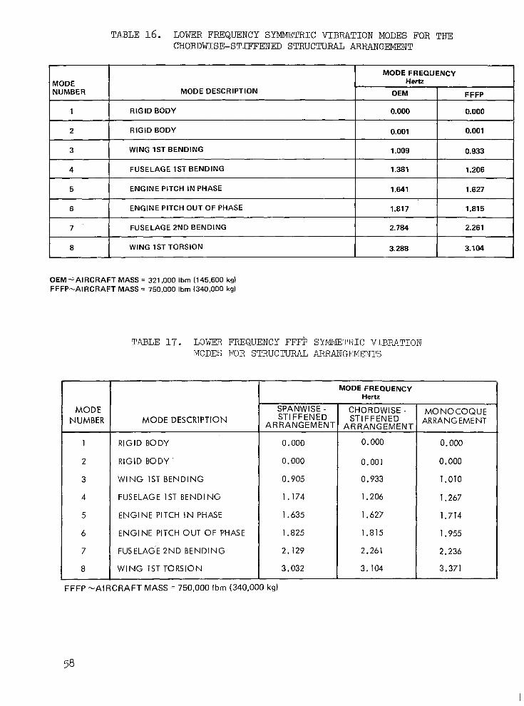
TABLE 16. LOWER FREQUENCY SYMMETRIC VIBMTION MODES FOR THE CHORDWISE-STIFFENED STRUCTURAL ARRANGEMENT
I I MODE FREQUENCY i MODE
OEM MODE DESCRIPTION NUMBER Hertz
i FFFP ~~
1 1 RIGID BODY I 0.000 I 0:ooo ~ 1 2
3
1.206 1.381 FUSELAGE 1ST BENDING 4
0.933 1.009 WING 1ST BENDING
5 1.627 1.641 ENGINE PITCH IN PHASE
6
2.261 2.784 FUSELAGE 2ND BENDING 7
1.81 5 1.817 ENGINE PITCH OUT OF PHASE
~~~ ~
8 3.104 3.288 WING 1ST TORSION
OEM-AIRCRAFT MASS = 321,000 Ibm (145.600 kg) FFFP-AIRCRAFT MASS = 750,000 Ibm (340,000 kg)
TABLE 17. LOWER FREQUENCY FFFP SYMMETRIC VIBRATION MODES FOR STRUCTURAL ARRANGEMENTS
MODE NUMBER
1
2
3
4
5
6
7
8
FFFP -AIRCRAFT
MODE DESCRIPTION
RIGID BODY
RIGID BODY'
W I N G 1ST BENDING
FUSELAGE 1ST BENDING
ENGINE PITCH IN PHASE
ENGINE PITCH OUT OF PHASE
FUSELAG'E 2ND BENDING.
WING 1ST TORSION
T SPANWISE - STIFFENED
ARRANGEMEN1
0.000
0.000
0.905
1.174
1.635
1.825
2.129
3.032
MASS 750,000 I bm (340,000
MODE FREQUENCY Hertz
0.000
0.000 0.001
0.000
0.933
1.206
1.627
1.815
2.261
3.104
1.010
1.267
1.714
1.955
2.236
3.371
1
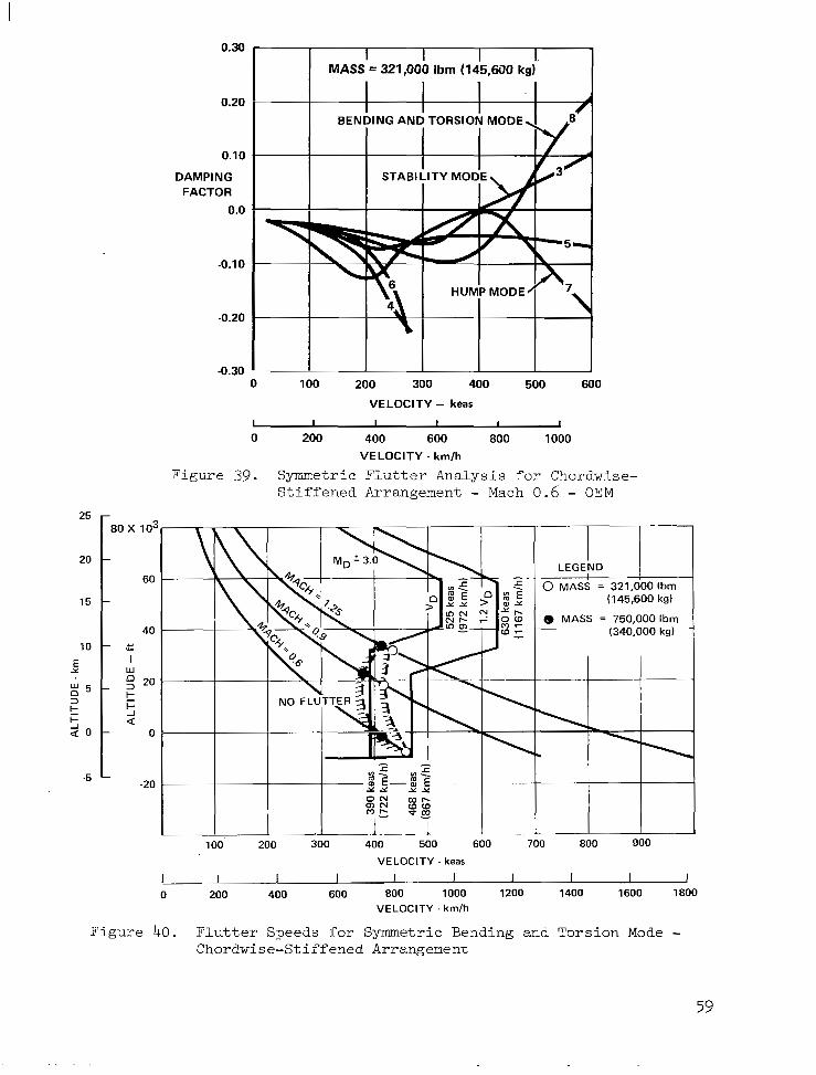
25
20
15
10
Y E
: 5
$ 0
3
I- k
-5
MASS I = 321,000 I Ibrn (145,mO I kg) I
0.20
0.10
DAMPING FACTOR
0.0
-0.10
-0.20
-0.30 0 100 200 300 400 500 600
VELOCITY - keas I I I I 1 I 0 200 400 600 800 1000
VELOCITY - km/h
Figure 39. Symmetric Flutter Analysis for Chordwise- Stiffened Arrangement - Mach 0.6 - OEM
80 x 10:
60
40 - Y
w I
2 20 k 5 a
0
-20
I I I I’ I I I I I 0 200 400 600 800 1000 1200 1400 1600 1800
VELOCITY - kmlh
Figure 40. Flutter Speeds for Symmetric Bending and Torsion Mode - Chordwise-Stiffened Arrangement
59

25
20
15
$0
w 0 3 k 5 5 a
0
-5
25
20
15
10
Y E
:5 3 t 2 0
-5
100 200 300 400 500 600 700 800 900 VELOCITY -keas
I I I I I I I I I 200 400 600 800 1000 1200 1400 1600 1800
VELOCITY - km/h
Figure 41. Flutter Speeds for Symmetric Hump Mode - Chordwise-Stiffened Arrangement
80 X 102
60
40
w 5 20
5 k
a 0
-20 St 200 400 600 800 1000 1200 1400 1600 1800
VELOCITY - km/h
Figure 42. Flutter Speeds for Symmetric Stability Mode - Chordwise-Stiffened Arrangement
1 I 100 200 300 400 500 600 700 800 900
VELOCITY -keas
60

FREQUENCY Hertz
3.0
2.0
1 .o
0
= MODES i O T S H O T
0.30
0.20
0.10
DAMPING FACTOR
0.0
.0.10
.0.20
.3.0 0 100 200 300 400 500 600 0 100 200 300 400 500 600
VELOCITY -keas VELOCITY -keas I I I I I 1 I I I I I 1 0 200 400 600 800 1000 0 200 400 600 800 1000
VELOCITY. kmlh VELOCITY. kvlh
Figure 43. Symmetric F l u t t e r A n a l y s i s - Mach 0.9 - FFFP Chordwise-Stiffened Arrangement
A s tudy w a s conducted t o a s s e s s t h e e f f e c t t h e wing t i p s t r u c t u r e h a d on t h e c o n t r o l o f t h e c r i t i c a l b e n d i n g and t o r s i o n mode. For t h i s i n v e s t i - gat ion, the chordwise-s t i f fened arrangement w a s a n a l y z e d f o r t h e FFFP con- d i t i o n w i t h t h e a i r c r a f t r i g i d i z e d e x c e p t f o r a f l e x i b l e wing outboard of B u t t l i n e 470. The f l u t t e r a n a l y s i s of t h i s c o n f i g u r a t i o n i n d i c a t e d t h a t f o r Mach 0.90, t h e wing 1st-bending mode r ap id ly i nc reases i n f r equency w i t h i n c r e a s i n g v e l o c i t y and coa lesces wi th the wing 1s t - tors ion mode t o f l u t t e r a t 418-keas (774-km/h). This f l u t t e r mechanism w a s i d e n t i c a l t o t h e f l u t t e r mechanism f o r t h e f l e x i b l e a i r c r a f t . F o r t h e f l e x i b l e a i r c r a f t , Figure 43, the bending and tors ion mode f l u t t e r v e l o c i t y was 379-keas (7OZ"km/h). Thus, i n f i n i t e s t i f f n e s s i n b o a r d o f BL470 i n c r e a s e d t h e f l u t t e r speed by only 1 0 percent . It i s e v i d e n t t h a t t h e w i n g - t i p s t r u c t u r e ( o u t e r wing) controls the bending-and-tors ion mode f l u t t e r mechanism.
Based on t h e r e s u l t s f o r t h e c h o r d w i s e - s t i f f e n e d d e s i g n , t h e most s ig - n i f i c a n t f l u t t e r c o n d i t i o n o c c u r r e d a t a Mach number of 0.90 f o r t h e FFFP c o n d i t i o n f o r t h e symmetric boundary condi t ion . This condi t ion was, t h e r e - f o r e , s e l e c t e d as t h e c a n d i d a t e f o r t h e f l u t t e r a n a l y s i s of t h e spanwise- s t i f f e n e d and monocoque wing des igns . Symmetric f l u t t e r s o l u t i o n s f o r t h e FFFP condi t ions a t Mach 0.90 are shown f o r t h e s p a n w i s e - s t i f f e n e d a n d t h e monocoque arrangements on Figures 44 and 45, r e s p e c t i v e l y . The a n a l y s i s of the spanwise-s t i f fened des ign ind ica tes on ly the bending and to rs ion mode and t h e s t a b i l i t y mode were ac t ive whereas the bending and torsion mode was t h e O n l y d i s t inc t mechan i sm.no ted fo r t he monocoque des ign . The f l u t t e r speeds for
61

0.20
0.10
a 0
0.00
L 2 " -0.10 I 2 a .::I]
.40 0 100 200 300 400 500 600
VELOCITY -keas
I I I I I 0 200 400 600 800 1000
VELOCITY - krn/h
Figure 44. Symmetric Flutter Analysis - Mach 0.9 - FFFP - Spanwise-Stiffened Arrangement
Figure 45.
0 100 200 300 400 500 600
VELOCITY - km/h
I I I I I I 0 200 400 600 8 0 0 TOO<
VELOCITY - k e a s
Symmetric Flutter Analysis - Mach 0 Monocoque Arrangement
.9 - FFFP -
62

the spanwise-stiffened and t h e monocoque arrangements were 364-keas (674- km/h) and '423-keas (783-km/h) , r e s p e c t i v e l y f o r t h e s m e t r i c bending and torsion-mode for the FFFP condition at Mach 0.90. For comparison purposes, t h e f l u t t e r speed for the chordwise-stiffened arrangement for the same condition w a s 379-keas (702-lan/h) .
Flut ter opt imizat ion: The v ib ra t ion and f lu t t e r ana lyses conducted on the chordwise-stiffened, the spanwise-stiffened, and the monocoque s t r u c t u r a l arrangements indicated that t h e symmetric bending and t o r s i o n mode f o r t h e FFFP condition a t Mach 0.90 r e su l t ed i n t he l owes t symmetric f l u t t e r speed. A review of the results of the foregoing analyses suggested that s t i f f e n i n g t h e wing t i p s t r u c t u r e would el iminate the hump mode f l u t t e r (symmetric and antisymmetric) and would permit the bending and torsion mode f lu t t e r speeds t o be pushed beyond t h e 1 .2 VD envelope. Incremental stiffness requirements and r e s u l t i n g mass a d d i t i o n s t o push t h e f l u t t e r speed beyond t h e 1 . 2 VD en- velope of 468-keas (867-km/h) were de te rmined for th ree s t ruc tura l arrangements .
To determine the effectiveness and t h e optimum d i s t r i b u t i o n of mater ia l within a par t icu lar reg ion of t h e a i r p l a n e , t h e wing planform was divided in to e ight reg ions p lus two add i t iona l r eg ions fo r t he two engine support beams. Figure 13a displays the locat ion of these ten regions on t h e wing planform.
The GFAM f lu t te r op t imiza t ion program w a s employed i n determining the most e f f e c t i v e r e g i o n f o r s t i f f n e s s and mass addi t ions to ach ieve the des i r ed f l u t t e r speed fo r each of the s t ructural arrangements .
The monocoque arrangement w a s a lso evaluated to determine the effect ive- ness of' the design regions to achieve the required f lut ter speed. Region 8 was again the most e f fec t ive reg ion , requi r ing 1240-lbm (562-kg) of add i t iona l s t ruc tu ra l ma te r i a l (pe r s ide ) t o i nc rease t he bend ing and t o r s i o n f l u t t e r ve loc i ty from 423-keas (783-km/h) t o 468-keas (867-km/h).
The f l u t t e r mass penalty for the spanwise-stiffened design w a s estimated using the data of the foregoing analyses , For both the chordwise-s t i f fened and monocoque arrangements, the incremental mass ( p e r a i r c r a f t ) r e q u i r e d t o r a i s e t h e f l u t t e r speed by one-keas (1.852-km/h) w a s 27.6 lbm (12.5-kg). Thus, a f lu t t e r pena l ty o f 2752-lbm (1248-kg) was added ( p e r a i r c r a f t ) t o the spanwise-stiffened arrangement.

400 -
350 - E. n -
m x t- I-
E
- w J 300 2
2 - 2 2 250 0 I U
0
I 6
3
u)
5 z
200 -
150 -
TOTAL MASS INCREMENT PER SIDE - Ibm I I I I I I I I
495 500 505 510 515 520 525 530
TOTAL MASS INCREMENT PER SIDE - kg
Figure 46. Flutter Optimization - Chordwise-Stiffened Arrangement
Cost Analyses
Detailed cost analyses were conducted on the five wing concepts sur- viving the structural analysis phase of the detail concept evaluation. These wing concepts were: (1) chordwise-stiffenedwingarrangement, beaded skin panels, mechanically fastened; (2) spanwise-stiffened. w i n g arrangement, hat-stiffened skin panels, mechanically fastened; (3) monocoque wing arrangement, aluminum brazed honeycomb sandwich skin panels, mechanically fastened; (4) monocoque wing arrangement, aluminum brazed honeycomb sand- wich skin panels, welded; and (5) composite-reinforced chordwise-stiffened wing arrangement, beaded skin panels, mechanically fastened. The cost of the most promising fuselage concept, a combination of zee- and hat- stiffened concepts, was not assessed since only the relative costs of the wing concepts were of interest and the fuselage concept would be applicable for all wing concepts.
Representative areas of the wing, coincident with the point design regions used for the structural analyses, were adopted. Three regions were selected for cost analysis: 40322, 40536, and 41348. The sizing data (i.e., skin thickness, cap size, etc.) in these regions were considered as representative for the wing forward box area, wing aft box area, and the wing tip, respectively. The major assembly costs for these three areas of the wing were then used to estimate average costs for the total wing structure.
64

Production wing panel s izes were determined f rom the prel iminary design drawings for each of the f ive wing d e s i g n s . I n g e n e r a l t h e s t r u c - ture w a s d i v i d e d i n t o s ix elements: the upper and lower skin assemblies p lus two d i f f e ren t spa r and r ib des igns . Th i s s t ruc tu ra l breakdown w a s t y p i c a l i n e a c h wing area (forward, a f t , t i p ) and fo r each wing design concept .
Product ion costs were es t imated for : (1) t h e weld-bonded beaded panel des ign , ( 2 ) t h e weld-bonded ha t -s t i f fened pane l des ign , and ( 3 ) t h e aluminum brazed honeycomb core sandwich design, using appropriate advanced p roduc ib i l i t y t echn iques . The spa r and r ib conf igu ra t ion cos t s were de ter - mined fo r each wing des ign , cons ider ing such fac tors as metal removal and welding requirements. Production manhours were developed us ing the jo in t designs consis tent with each design concept .
F a b r i c a t i o n d a t a f o r t h e u p p e r and lower skin assemblies were estimated b y t h e manhours and material: mass per square foot of each panel . The f a b r i c a t i o n d a t a for t h e l i n e a r s t r u c t u r e , s u c h as caps, webs, e t c . , were de termined by the l inea l foo t . All assembly data were based on type of jo in t des ign , such as number of fas teners , l ength o f weld , e tc . , and were a l s o e s t i m a t e d b y t h e l i n e a l f o o t .
For e a c h d e s i g n c o n c e p t , t h e t o t a l manhours, material cos t s and t oo l - make manhours t o manufacture the f i r s t p r o d u c t i o n a i r c r a f t were developed f o r t h e f o r w a r d , a f t , and wing t i p a r e a s . T a b l e 18 sunmasizes these results i n a d d i t i o n t o p r e s e n t i n g t h e wing mass fo r each wing design con- c e p t . A summary of the p roduct ion cos ts in t e rms of "va lue per pound" are t abu la t ed i n Tab le 19. These "value per pound" increments a re used as t h e cos t input da ta for Lockheed-Cal i forn ia ' s ASSET (Advanced System Synthesis and Evaluation Technique) computer program (Reference 1).
Concept Se lec t ion
The various wing design concepts, each with a convent ional skin- s t r inger - f rame fuse lage des ign , were eva lua ted wi th respec t to s t ruc tura l mass, performance and cost using the ASSET computer program. These f a c t o r s were i n t e r r e l a t e d t o y i e l d c o m p a r i s o n d a t a f o r b o t h a cons tan t mass air- c r a f t and a cons tan t payload-range a i rc raf t .
The s t r u c t u r a l mass d a t a f o r t h e t h r e e main segments of t h e wing s t r u c t u r e are shown i n T a b l e 20 f o r t h e f ive s t ruc tura l a r rangements . These wing masses are d i v i d e d i n t o two major categories: . a variable and a f i x e d mass increment for each wing design. The variable mass c o n s i s t s of t h a t po r t ion o f t he box s t ruc tu re wh ich i s ca l cu la t ed f rom the r e su l t s of t h e ultimate and f a t igue s t r eng th , f a i l - s a fe and son ic f a t igue ana lyses con- ducted on a po in t des ign basis, as w e l l as, t h e results o f t h e o v e r a l l a i r c r a f t f l u t t e r e v a l u a t i o n s . The f i x e d mass c o n s i s t s o f t h o s e items which are unaf fec ted by box s t ruc tu ra l concep t , such as main landing gear p rov i s ions , su r f ace con t ro l s , eng ine suppor t s t ruc tu re , and l ead ing and t r a i l i n g edge structui-e.
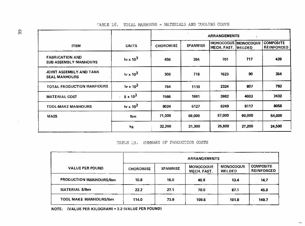
TABLE 18. TOTAL MANHOURS - MATERIALS AND TOOLING COSTS
I ARRANGEMENTS )
ITEM UNITS CHoRDWISE SPANWISE MECH. FAST. WELDED MONOCOQUE MONOCOQUE COMPOSITE
REINFORCED
FABRICATION AND SUB ASSEMBLY MANHOURS
h rx IO3 1 456 I 394 I 701 I 717 1 439
JOINT ASSEMBLY AND TANK SEAL MANHOURS
TOTAL PRODUCTION MANHOURS 1110 2324 807 793
MATERIAL COST 1881 3982 4033 2432 1 TOOL-MAKE MANHOURS hr :r , -Il 8024 1 5127 1 6249 1 6117 1 8058
MASS 71,000 69,000 57,000 60,000 54,000
32,200 31,300 25,800 27,200 24,500
TABLE 19 . SUMMARY OF PRODUCTION COSTS
i ARRANGEMENTS
VALUE PER POUND COMPOSITE MONOCOQUE MONOCOQUE SPANWISE CHORDWISE MECH. FAST. REINFORCED WELDED
PRODUCTION MANHOURS/lbrn
101.8 109.6 73.9 114.0 TOOL MAKE MANHOURS/lbrn
45.0 67.1 70.0 27.1 22.2 MATERIAL $/lbm
14.7 13.4 40.8 16.0 10.8
. 149.7
NOTE: (VALUE PER KILOGRAM) = 2.2 (VALUE PER POUND)

TABLE 20. WING MASS FOR STRUCTURAL ARRANGEMENTS
1 WING
I STRUCTURAL ARRANGEMENT I
MASS SEGMENT AND ml I I MECH. FASTEN. I I I I
VARIABLE MASS Ibm (ka) I 64,658 (29.3281
1 0 FWD.BOX (ka) ibk 1- (10.020)
0 AFT BOX 29.016 (13.161) I 0 TIP Ibm 13,552 (6.147)
(18,757) FIXED MASS
Z TOTAL- (48.085)
I I I SPANWISE 1 MONOCOQUE I CHORDWISE
WELDBOND 1 ALUM BRAZED I ALUM BRAZED COMP. REINF.
MECH. FASTEN. I MECH. FASTEN. WELDED SPARS ONLY
63.482 50,978 53.794 48,082 (28,795) (23,123) (24,400) (21,810) 25.364 fi.982 24.057 zo.wO I
. (7,886) 12,876
41,352 41,352 41,352 41,352 ( 18,757) (18,757) (18,757) ( 18,757)
104,834 92,330 95,146 89,434 (47,552) (41,880) (43,157) (40,566)
The component and t o t a l mass f o r t h e most promising fuselage approach i s shown in Tab le 21. The results of the po in t des ign ana lyses are r e f l e c t e d i n t h e s h e l l mass which t o t a l s 23,148-lbm (10,500-kg). The t o t a l fu se l age mass i s 42,688-lbm (19,363-kg), which includes 19,540-lbm (8,863- kg ) o f f i xed mass as d e l i n e a t e d i n t h e l o w e r p o r t i o n o f t h i s t a b l e .
In conjunct ion wi th the a forement ioned wing and fuse lage mass d a t a , t he p roduc t ion cos t s were input da ta for the ASSET program syn thes i s o f t he cons t an t mass and cons tan t payload-range a i rc raf t .
Constant Mass Ai rc ra f t . -The s t ruc tu ra l mass o f t h e a i r c r a f t w a s es t imated fo r each o f t he cand ida te s t ruc tu ra l app roaches based on the p remise o f a f i x e d v e h i c l e s i z e a n d t a x i mass of 750,000-lbm (340,000-kg). This per- m i t t e d t h e d e t e r m i n a t i o n o f t h e a l l o w a b l e f u e l f o r t h e a i r c r a f t ; h e n c e t h e r a n g e c a p a b i l i t y , RDT&E, p roduct ion and main tenance cos ts , fo r each of the candidate s t ructural approaches were determined. A direct comparison of t h e s t r u c t u r a l mass, range and cost w a s made on t h e b a s i s o f c o n s t a n t a i rp l ane conf igu ra t ion and gross mass (Table 22a) . A comparison of the var ious parameters ( i . e . , s t r u c t u r a l mass, r a n g e , c o s t ) f o r t h e c o n s t a n t size/mass a i r c r a f t i n d i c a t e d a. va r i a t ion i n t hese pa rame te r s and t he minimum d id no t necessa r i ly i den t i fy t he bes t concep t . The minimum-mass wing concept was the composi te-reinforced chordwise-s t i f fened design; the spanwise-s t i f fened design w a s , however, t h e l e a s t i n i t i a l c o s t c o n c e p t as t y p i f i e d by the f lyaway cos t . It can be s een f rom the t abu la t ed da t a t ha t t h e mass sav ings r ea l i zed by t he app l i ca t ion o f compos i t e s t o t he spa r caps permits approximately 16,600-1bm (7530-kg) o f a d d i t i o n a l f u e l t o b e c a r r i e d . Hence, t h e r a n g e c a p a b i l i t y of t he s t ruc tu ra l ly e f f i c i en t compos i t e - r e in fo rced des ign was approximately 340-nmi (630-km) grea te r than the bas ic chordwise-
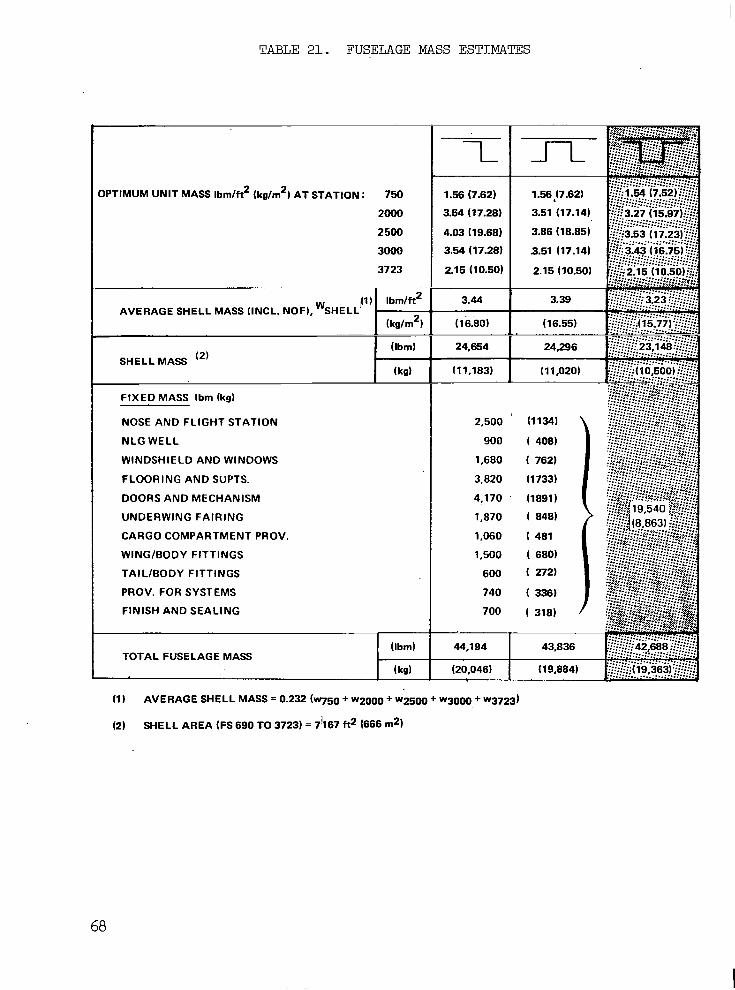
TABLE 21. FUSELAGE MASS ESTIMATES
OPTIMUM UNIT MASS Ibm/ft2 (kg/m2) AT STATION : 750
2000
2500
3-
3723 I
FIXED MASS Ibm (kg)
NOSE AND FLIGHT STATION
NLG WELL
WINDSHIELD AND WINDOWS
FLOORING AND SUPTS.
DOORS AND MECHANISM
UNDERWING FAIRING
CARGO COMPARTMENT PROV.
WING/BODY FITTINGS
TAILlBODY FITTINGS
PROV. FOR SYSTEMS
FINISH AND SEALING
TOTAL FUSELAGE MASS
1.56 (7.62)
3.54 (17.28)
4.03 (19.68)
3.54 (17.28)
2.15 (10.50)
3.44
( 16.80)
24,654
(11,183) ~
2,500
900
1,680
3.820
4! 170
1,870
1,060
1,500
600
740
700
”
44.194
(20,046)
68
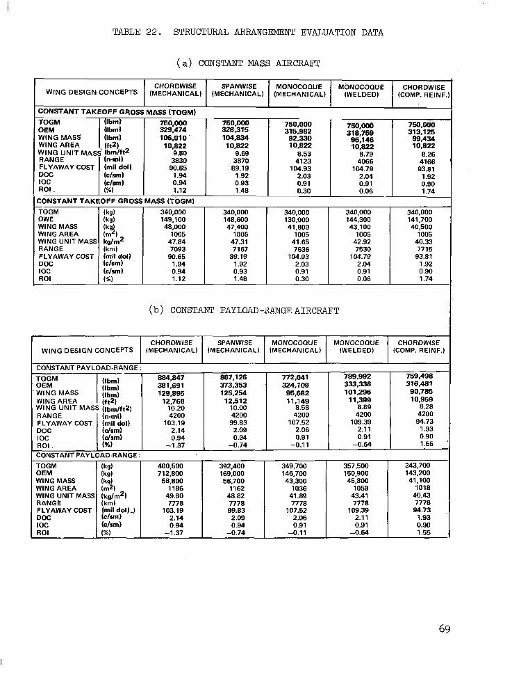
TABLE 22. STRUCTURAL ARRANGEMENT EVALUATION DATA
(a) CONSTANT MASS AIRCFWT
WING DESIGN CONCEPTS CHORDWISE MONOCOQUE MONOCOQUE SPANWISE CHORDWISE
(COMP. RElNF (WELDED) (MECHANICAL) (MECHANICAL) (MECHANICAL)
CONSTANT TAKEOFF GROSS
(Ibm) MASS (TOQM)
OEM ( I b d 329.474 750,000
(Ibm) 106.01 0 ' 328.315 750,000 isO,ooi, 750.000 750,000
104.834 315,982 318,759 31 3.1 25 92,330 95.1 46 89,434
10,822 10,822 10,822 10,822 10,822 9.80 9.69
3830 3870 8.53 8.79 8.26
41 23 90.65
4066 4166 89.19
(clsm) 1.94 104.93 104.79
1.92 93.81
(clsm) 2.03
0.94 2.04 1.92
0.93 0.91 1.12
0.91 1.48 0.30 0.06 1.74
0.90
..
FLYAWAY COST (mil'doll
WING AREA
ROI
149,100 48.000
1005 47.84
90.65 7093
0.94 1.94
1.12 1
340,000 148,600 47.400
1005 47.31
89.19 7167
1.92 0.93 1.48
340,000 130.000 41,800
1005 41.65 7636
104.93 2.03 0.91 0.30
144,300 43,100
1005 42.92
104.79 7530
2.04 0.91 0.06
(b) CONSTANT PAYLOAD -RANGE AIRCRAFT
340,000 141.700 40,500
1005 40.33
93.81 7715
1.92 0.90 1.74
I WING DESIGN CONCEPTS CHORDWISE SPANWISE MONOCOQUE MONOCOQUE
(MECHANICAL) (MECHANICAL) (MECHANICAL) (WELDED) CHORDWISE
(COMP. REINF.) .. "
I I I I I ' CONSTANT PAYLOAD-RANGE
TOGM 884,847
90,785 101,296 95,682 125,254 129,895 (Ibm) . WING MASS OEM
759,498 789.992 772,641 867.1 26
WING AREA ( f a 12,768 12,512 11,149 1 1,399 8.28 8.89 8.58 10.00 10.20 WING UNIT MASS (lbm/ft2)
10,959
- (Ibml (Ibm) 324,109 373,353 381,691 333,338 316,481
~. RANGE
1.93 2.1 1 2.06 2.09 2.14 (drm) DOC 94.73 109.39 107.52 99.83 103.19 (mil dol) FLYAWAY COST 4200 4200 4200 4200 4200 (n-mi)
ROI . , ( 4 6 ) -1.37 -0.74
CONSTANT PAYLOAD-RANGE :
1.55 -0.64 -0.11 I oc 0.90 0.91 0.91 0.94 0.94 (drm)
~~
TOGM OEM WING MASS WING AREA WING UNIT MASS RANGE FLYAWAY COST DOC IOC ROI
400>00 712.800 58,800
49.80 1186
7778 103.19
2.14 0.94
-1.37
392,400 169,000 56.700
1162 48.82
99.83 7778
2.09 0.94
-0.74
349.700 146,700 43.300
1036 41.89 7778
107.52 2.06 0.91
-0.11
357.500 150,900 45.800
1059 43.41 7778
1 109.39 2.1 1 0.91
-0.64
343,700 143,200 41,100
1018 40.43 7778 94.73
0.90 1.93
1.55
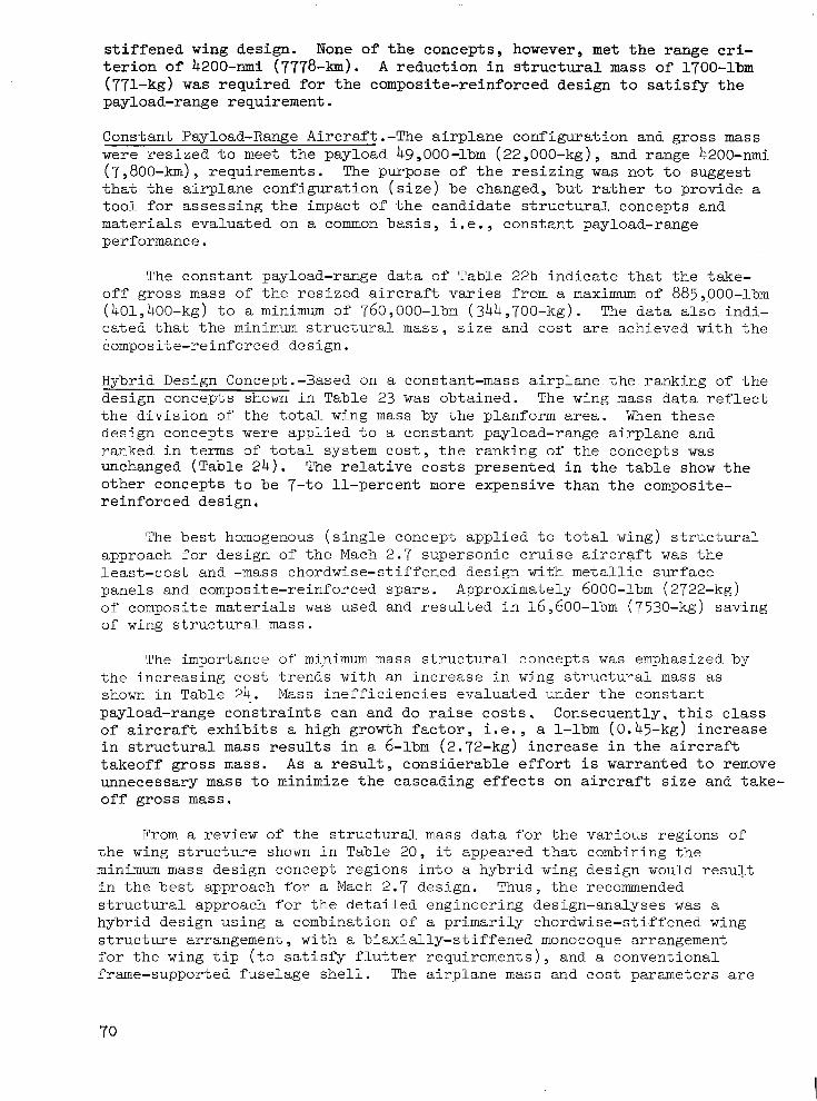
s t i f fened wing des ign . None of the concepts, however, met t h e r a n g e cr i - t e r i o n of 4200-mi (7778-b). A r e d u c t i o n i n s t r u c t u r a l mass of 1700-lbm (771-kg) w a s r e q u i r e d f o r t h e c o m p o s i t e - r e i n f o r c e d d e s i g n t o satisfy t h e payload-range requirement.
Constant Payload-Range Aircraft .-The airplane configuration and gross mass were r e s i z e d t o meet the payload 49,000-lbm (22,000-kg), and range 4200-nmi (7,800-km), requirements . The purpose o f t he r e s i z ing w a s n o t t o s u g g e s t t h a t t h e a i r p l a n e c o n f i g u r a t i o n ( s i z e ) be changed , bu t r a the r t o p rov ide a t o o l f o r a s s e s s i n g t h e i m p a c t of t h e c a n d i d a t e s t r u c t u r a l c o n c e p t s a n d materials evaluated on a common b a s i s , i . e . , constant payload-range performance.
The constant payload-range data of Table 22b i n d i c a t e t h a t t h e take- o f f g ros s mass of the r e s i z e d a i r c r a f t varies from a maximum of 885,000-1bm (401,400-kg) t o a minimum of 760,000-lbm (344,700-kg). The d a t a a1s.o ind i - ca ted t ha t t h e minimim s t r u c t u r a l mass, s i z e and cost are achieved w i t h t h e composite-reinforced design.
Hybrid Design Concept.-Based on a cons tan t -mass a i rp lane the ranking of the design concepts shown in Table 23 was obta ined . The wing mass d a t a r e f l e c t t h e d i v i s i o n o f t h e t o t a l wing mass by the planform area. When t h e s e design concepts were appl ied t o a constant payload-range airplane and r anked i n t e rms o f t o t a l sys t em cos t , t h e ranking of the concepts was unchanged (Table 2 4 ) . The re la t ive c o s t s p r e s e n t e d i n t h e t a b l e show t h e o ther concepts to be 7 - to 11-percent more expensive than the composi te- r e in fo rced des ign ,
The b e s t homogenous ( s i n g l e c o n c e p t a p p l i e d t o t o t a l w i n g ) s t r u c t u r a l approach for des ign of t h e Mach 2 . 7 s u p e r s o n i c c r u i s e a i r c r a f t was t h e leas t -cos t and -mass chordwise-s t i f fened design w i t h m e t a l l i c s u r f a c e panels and composite-reinforced spars. Approximately 6000-1bm (2'722-kg) of composi te mater ia ls w a s u sed and r e su l t ed i n 16,600-1bm (7530-kg) saving of wing s t r u c t u r a l mass.
The importance of mi,nimum mass s t ruc tu ra l concep t s was emphasized by t h e i n c r e a s i n g c o s t t r e n d s w i t h a n i n c r e a s e i n wing s t r u c t u r a l mass as shown in Tab le 24. Mass ine f f i c i enc ie s eva lua ted unde r t he cons t an t payload-range constraints can and do raise c o s t s . C o n s e a u e n t l y . t h i s c l a s s o f a i r c r a f t e x h i b i t s a h igh g rowth f ac to r , i . e . , a 1-lbm (0.45-kg) increase i n s t r u c t u r a l mass r e s u l t s i n a 6-1bm ( 2 . 7 2 - k g ) i n c r e a s e i n t h e a i r c r a f t t akeof f g ros s mass. A s a r e s u l t , c o n s i d e r a b l e e f f o r t i s w a r r a n t e d t o remove unnecessary mass t o minimize the cascading e f fec ts on a i r c r a f t s i z e and take- o f f g r o s s mass.
From a rev iew of the s t ruc tura l mass d a t a f o r t h e v a r i o u s r e g i o n s o f t h e wing s t r u c t u r e shown i n Table 20, it appeared that combining the minimum mass des ign concept reg ions in to a hybr id wing des ign would r e s u l t i n t h e bes t approach for a Mach 2.7 design. Thus, t he recommended s t ruc tura l approach for the de ta i led engineer ing des ign-ana lyses was a hybrid design using a combination of a pr imari ly chordwise-s t i . f fened wing s t ruc ture a r rangement , wi th a b i a x i a l l y - s t i f f e n e d monocoque arrangement f o r t h e wing t i p ( t o s a t i s f y f l u t t e r r e q u i r e m e n t s ) , and a convent ional frame-supported fuselage she l l . The a i r p l a n e mass and cost parameters are
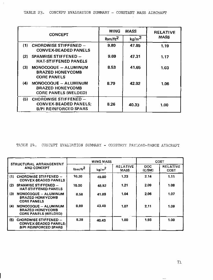
TABLE 23. CONCEPT WALUATION SUMMARY - CONSTANT MASS AIRCRAFT
". .. ~ ~ ~ _ _ _ ~
CONCEPT
. "~ ~ ~ . .""
(1) CHORDWISE STIFFENED - CONVEX-BEADED PANELS
(2) SPANWISE STIFFENED - HAT-STIFFENED PANELS
(3) MONOCOQUE -ALUMINUM BRAZED HONEYCOMB CORE PANELS
(4) MONOCOQUE - ALUMINUM BRAZEDHONEYCOMB CORE PANELS (WELDED)
~ ~~
(5) CHORDWISE STIFFENED- CONVEX-BEADED PANELS; B/PI REINFORCED SPARS
~.
WING MASS
Ibrn/ft2 9.80
9.69
8.53
8.79 ! 1
kdm2
47.85
47.31
41.65
42.92
40.33
RELATIVE MASS
1.19
1.17
1.03
1.06
1 .oo
TABLE 24. CONCEPT EVALUATION SUMMARY - CONSTANT PAYLOAD-RANGE AIRCRAFT
STRUCTURAL ARRANGEMENT AND CONCEPT
(1) CHORDWISE STIFFENED - CONVEX-BEADED PANELS
(2) SPANWISE STIFFENER - HAT-STIFFENED PANELS
(3) MONOCOQUE - ALUMINUM BRAZED HONEYCOMB CORE PANELS
(4) MONOCOQUE -ALUMINUM BRAZED HONEYCOMB CORE PANELS (WELDED)
(5) CHORDWISE STIFFENED - CONVEX-BEADED PANELS; B/PI REINFORCED SPARS
T I b m / h 2 m "
WING MASS
2
10.00 48.82
8.58 41.89
8.89 43.40
1 40.43
r - = RELATIVE W S M )
2.14
2.09
2.06
2.1 1
RELATIVE COST
1.11
1.08
1.07
1.09
1 .oo
71

shown i n Table 25 for this hybrid design, for both the constant-mass and the constant payload-range cri teria. A s indicated, th is prel iminary design very nearly satisfies the payload-range requirements specified for . the 750,000-lbm (340,000-kg) baseline configuration.
TABLE 2 5 . EVALUATION DATA FOR HYBRID STRUCTURAL ARRANGEMENT
STRUCTURAL ARRANGEMENT
HYBRID ARRANGEMENT (MECHANICALLY FASTENED)
I CONSTANT MASS AIRCRAFT
TOGM
1.91 (c/sm) DOC 93.57 (mil dol) FLYAWAY COST
(7,747) 41 83 n mi (km) RANGE (40) 8.19 2 2
Ibm/ft (kg/m ) WING UNIT MASS (1,005) 10,822 ft2 (m2) WING AREA
(40,200) 88,620 Ibm (kg) WING MASS (141,700) 312,322 Ibm (kg) OEM (340,000) 750,000 Ibm (kg)
ROI A.T. (%) 1.82 I oc 0.90 (c/sm)
CONSTANT PAYLOAD-RANGE AIRCRAFT
TOGM
Ibm (kg4 WING MASS (142,400) 31 3,963 Ibm (kg) OEM (342,300) 754,665 Ibm (kg)
(7778) 4200 n.mi (kn?) RANGE (40) 8.20 Ibm/ft*(kg/m 2 j WING UNIT MASS
(1,012) 10,889 ft2 - (m ) WING AREA (40,500) 89,2 1 6
FLYAWAY COST (mil dol) 94.02 DOC (c/sm) 1.92 I oc (c/sm) 0.90 ROI A.T. 1.73 (c/o)
72
"".. .. ._. .. ....._ .. , .,. ,.. . .-,.._ , , . . .. ..
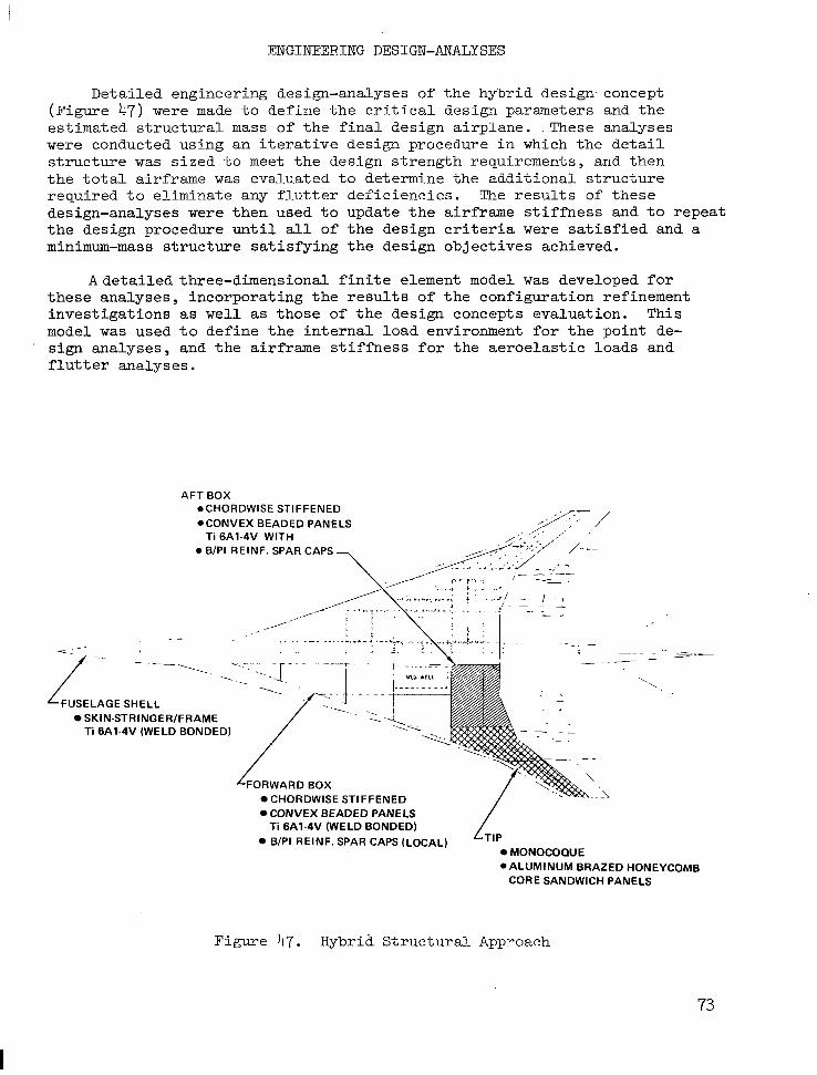
ENGINEERING DESIGN-ANALYSES
Detailed engineering design-analyses of the hybrid design- concept (Figure 47) were made to de f ine t he c r i t i ca l des ign pa rame te r s and t h e es t imated s t ruc tura l mass of the f inal design airplane. .These analyses were conducted using an i te ra t ive des ign procedure in which t h e d e t a i l s t r u c t u r e was s i z e d t o meet the design strength requirements, and then t h e t o t a l a i r f r a m e w a s eva lua ted to de te rmine the addi t iona l s t ruc ture r equ i r ed t o e l imina te any f l u t t e r de f i c i enc ie s . The r e s u l t s of t hese design-analyses were then used t o update the a i r f rame s t i f fness and t o r e p e a t the design procedure unt i l a l l of t h e d e s i g n c r i t e r i a were s a t i s f i e d and a minimum-mass s t ruc ture sa t i s fy ing the des ign ob jec t ives ach ieved .
Adetailed three-dimensional f inite element model was developed f o r these analyses , incorporat ing the resul ts of the configurat ion ref inement inves t iga t ions as wel l as those of the design concepts evaluation. This model was used t o d e f i n e t h e i n t e r n a l l o a d environment f o r t h e p o i n t de-
f lu t t e r ana lyses . ' sign analyses, and the airframe s t i f f n e s s f o r t h e a e r o e l a s t i c l o a d s and
AFT BOX .CHORDWISE STIFFENED *CONVEX BEADED PANELS ,/-,/
0 B/PI REINF. SPAR CAPS Ti 6A1-4V WITH ;;, ' ,_ ,/' '
,.
- - ."
/ \
FUSELAGE SHELL SKIN-STRINGER/FRAME Ti 6A1-4V (WELD BONDED)
-. . " '. .. ' " - -.
2. - ".
CHORDWISE CONVEX BEADED PANELS Ti 6A1-4V (WELD BONDED) B/PI REIN;. SPAR CAPS (LOCAL) L ~ l ~
~.
MONOCOQUE
" . "
c c
\ ',
0 ALUMINUM BRAZED HONEYCOMB CORE SANDWICH PANELS
Figure 47. Hybrid S t r u c t u r a l Approach
73
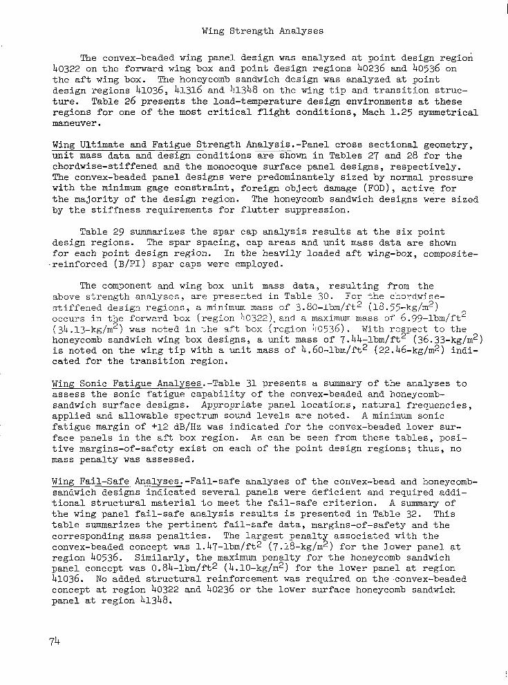
Wing Strength Analyses
The convex-beaded wing panel design was analyzed at point design region 40322 on the forward wing box and point design regions 40236 and 40536 on the aft wing box. The honeycomb sandwich design was analyzed at point design regions 41036, 41316 and 41348 on the wing tip and transition struc- ture. Table 26 presents the load-temperature design environments at these regions for one of the most critical flight conditions, Mach 1.25 symmetrical maneuver.
Wing Ultimate and Fatigue Strength Analysis.-Panel cross sectional geometry, unit mass data and design conditions are shown in Tables 27 and 28 for the chordwise-stiffened and the monocoque surface panel designs, respectively. The convex-beaded panel designs were predominantely sized by normal pressure with the minimum gage constraint, foreign object damage (FOD), active for the majority of the design region. The honeycomb sandwich designs were sized by the stiffness requirements for flutter suppression.
Table 29 summarizes the spar cap analysis results at the six point design regions. The spar spacing, cap areas and unit mass data are shown for each point design region. In the heavily loaded aft wing-box, composite- ,reinforced (B/PI) spar caps were employed.
The component and wing box unit mass data, resulting from the above strength analyses, are presented in Table 30. For the chordwise- stiffened design regions, a minimum mass of 3.80-lbm/ft2 (18. 55-kg/m2) occurs in the forward box (region 40322).and a maximum mass of 6.99-lbm/ft 2
(34 .13-kg/m2) was noted in the aft box (region 40536). With respect to the honeycomb sandwich wing box designs , a unit mass of 7. 44-lbm/ft2 (36. 33-kg/m2) is noted on the wing tip with a unit mass of 4,60-lbm/ft2 (22.46-kg/m2) indi- cated f o r the transition region,
Wing Sonic Fatigue Analyses.-Table 31 presents a summary of the analyses to assess the sonic fatigue capability of the convex-beaded and honeycomb- sandwich surface designs. Appropriate panel locations, natural frequencies, applied and allowable spectrum sound levels are noted. A minimum sonic fatigue margin of +12 dB/Hz was Tndicated for the convex-beaded lower sur- face panels in the aft box region. As can be seen from these tables, posi- tive margins-of-safety exist on each of the point design regions; thus, no mass penalty was assessed.
Wing Fail-safe Analyses.-Fail-safe analyses of the convex-bead and honeycomb- sandwich designs indicated several panels were deficient and required addi- tional structural material to meet the fail-safe criterion. A summary of the wing panel fail-safe analysis results is presented in Table 32. This table summarizes the pertinent fail-safe data, margins-of-safety and the corresponding mass penalties. The largest penalty associated with the convex-beaded concept was 1. 47-lbm/ft2 (7.18-kg/m2) for the lower panel at region 40536. Similarly, the maximum penalty for the honeycomb sandwich panel concept was 0.84-lbm/ft2 ( 4.10-kg/m2) for the lower panel at region 41036. No added structural reinforcement was required on the.convex-beaded concept at region 40322 and 40236 or the lower surface honeycomb sandwich panel at region 41348,
74
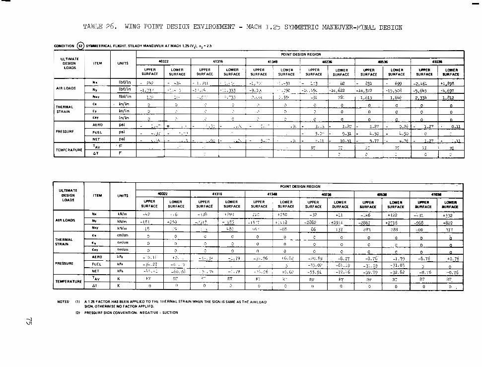
TABLE 26. WING POINT DESIGN ENVIRONMENT - MACH 1 .25 SYMMETRIC MANEUVER-FINAL DESIGN
UWlD lT lON 12 SYMMETRICAL FLIGHT, STEADY MANEUVER AT MACH 1.25 IVJ. nz = 2.5 pF UNITS UPPER 40322 41316 41 248 POINT DESIGN REGION 402% 405% 410% f
LOWER L W E R UCCER LOWER UPPER LOWER UPPER LOWER UPPER LOWER ' UPPER SURFACE SURFACE SURFACE SURFACE SURFACE SURFACE SURFACE SURFACE SURFACE SURFACE SURFACE SURFACE
AIR LOADS
I
f, 0 0 1 THERMAL STRAIN CY
cm cm
cmlcm 0 0 0 0 0 0 0 0
0 0 0 0 0 0 0
AERO +0...: -10.11, k Pa - > - . jq
t0.76 -0.76 -32.02 -79.70 -72.46 -55.91 +6.62 -:.'..?6 -1 .79 -3q.34 -60.26 -LL.b1 kPa NET 1 -o: . . '9 -3L.27 kPa FUEL
to. 76 -8.76 -1.79 -0.76' -0.27 -20.89 +6.62 -3-.?6 -1 .79 PRESSURE
J 0 -31.03 -31.03 -64.19 -35.02 3
I TEMPERATURE I TAV RT RT RT RT RT FT RT I *T I Rr
I RT I RT- RT
AT I n 0 0 0 0 0 0 0 0 0 I I 0 [ 0 .
NOTES' I1 I A 1 25 FACTOR HAS BEEN APPLIED TO THE THERMAL STRAIN WHEN THE SIGN IS SAME AS THE AIRLOAD SIGN, OTHERWISE NO FACTOR APPLIED.
121 PRESSURE SIGN CONVENTION. NEGATIVE = SUCTION

TABLE 27. CONVEX-BEADED PANEL DATA
I I POINT DESIGN REGIONS
40236 40536
UPPER LOWER UPPER LOWER f 40322
DESIGN DATA UPPER LOWER
SPACING, in..(m)
SPAR 60.0 (1.52) 60.0 21.2 (0.54) 21.2
,015 1.0381 .020 ,015 1.0381 ,020 .BO (2.031 1.00 87 (1.52) 87
2.35 (5.971 2.75 .75 (1.90) .75
,036 1.091) ,048 ,829 (4.05) 1.11
16 16 16
(0.381 10.51 1 (2.541 (1.52) (1.90) (6.98)
LlW) (4.6)
CRITICAL DESIGN COND. 12 12 20 20
I I DIMENSIONS:
TABLE 28. HONEYCON3 SANDWICH PANEL DATA
POINT DESIGN REGIONS
16 I 41316 I 41 8
DESIGN DATA UPPER
SPACING, in. (m)
SPAR 21.2 (0.54) 60.0 (1.52)
LOWER UPPER
60.0 ( 1.52) 40.0 (1.02) 21.2 (0.54) 40.0 11.02)
,202 (.513)
,500 (1.27) ,002 (.005) ,002 (.005)
,062 (.1571 ,023 (.058) ,062 (.157) ,028 (.071)
1.00 (2.54)
.500 (1.27)
,052 (.132) 3.02 (14.74) 1.20 (5.861 ,131 (.332)
12 FLUlTER
LOWER UPPER
40.0 (1.02) 30.0 (0.76) 40.0 (1.02) 40.0 (1.02)
.500 (1.27)
.002 (.005) .002 (.005)
,068 (.172) ,075 (.190) ,068 (.172) ,075 (.190)
1.00 (2.54)
.500 (1.27) ,500 (1.27)
3.52 (17.19) ,143 (.363) ,153 (.388) 3.29 (16.061
FLUTTER FLUTTER
LOWER
40.0 (1.02) 30.0 (0.76)
,500 (1.27) ,068 (.172) .068 (.172) ,002 (.005) .500 (1.27)
.139 (.353) 3.20 (15.62
FLUTTER
DIMENSIONS
H. in. (cm) tl , in. (cm) t2, in. (cm) tC, in. (cm) S. in. (cm)
MASS DATA t, in. (em) -
W. Ib./h2 (kglm21
,642 (1.63)
,018 (.046) ,026 (.067)
,002 (.005) ,275 (.698)
,052 (.132) 1.20 (5.86) a CRITICAL DESIGN COND.
DIMENSIONS
H
I THICKNESS tC= CORE FOIL
t
EXTERIOR SURFACE
76

TABLE 29. S ~ Y OF WING SPAR c m DATA
-~
POINT DESIGN REGION
40322
40236
40536
41036
41 316
41 348
NOTES:
~ ~-
SPAR SPACING
b
r r MASS CAP
W 1 r AC I AM CAP LOCATION m
- kg/m2
1.17
2.00
-
- 6.00
8.35 -
5.96
7.86 -
3.37
3.56
- 0.59
0.59 ~
0.78
0.68 ~
~
cm2 -
1.55
2.58
~
2.90
2.90 ~
2.90
2.90 - 2.90
2.90
1.35
1.16
1.35
1.16
~
cm2 ~
1.55
2.58
~
12.64
19.03 ~
12.58
17.74 "_ 5.55
6.12
~~
1.35
1.16 "
1.35
1.16 "
CAP DESIGN ~~
ALL METAL
CAP 6AI-4V T i
64I-4V Ti CAP WITH WPI REINF
6AI-4V Ti CAP WITH B/PI REINF.
6AI-4V T i CAP WITH B&PI REINFORCEMENT
ALL METAL 6AI-4V Ti CAP
ALL METAL 6AI-4V Ti CAP
in. ~
Ibm/ft2 ~
0.24
0.41
- 1.23
1.71 ~
1.22
1.61 ~
0.69
0.73
~
0.12
0.12 ~
0.16
0.14 ~
cm2 in.' ~. ~
- 0.24
- 0.40
. ~~
9.74 0.45
6.13 0.45 -~~ ~
9.68 0.45
14.84 0.45 ~~
2.64 0.45
3.22 0.45
- 0.21
- 0.18
-
0.18 - 0.21
22.7
22.7
21.2
21.2
21.2
21.2
21.2
21.2
40.0
40.0
30.0
30.0
0.577
0.577
0.538
0.538
0.538
0.538
0.538
0.538
1.016
1.016
0.762
0.762 . .~
- -
1.51
2.50
0.24
0.40
UPPER
LOWER
1.96
2.95
UPPER
LOWER
1.50
2.30 ~
0.41
0.50
- -
- -
1.95
2.75 - .
0.86
0.95
0.21
0.18
0.21
0.18
UPPER
LOWER
UPPER
LOWER
UPPER
LOWER .. ~
UPPER
LOWER
AC = COMPOSITE AREA
AM = METAL AREA
ATOTAL = AC + A M
pc = COMPOSITE (B/PI) DENSITY; 0.072 I b ~ n l i n . ~ (1993 - kg/&)
p~ = METAL (6A14Vl DENSITY; 0.160 I b n ~ l i n . ~ (4429 - kg/m*l
b = SPAR SPACING W = EQUIVALENT SURFACE PANEL MASS
144(Ac PC + AM PM)/b ~ . ~
_ _ _ ~
77
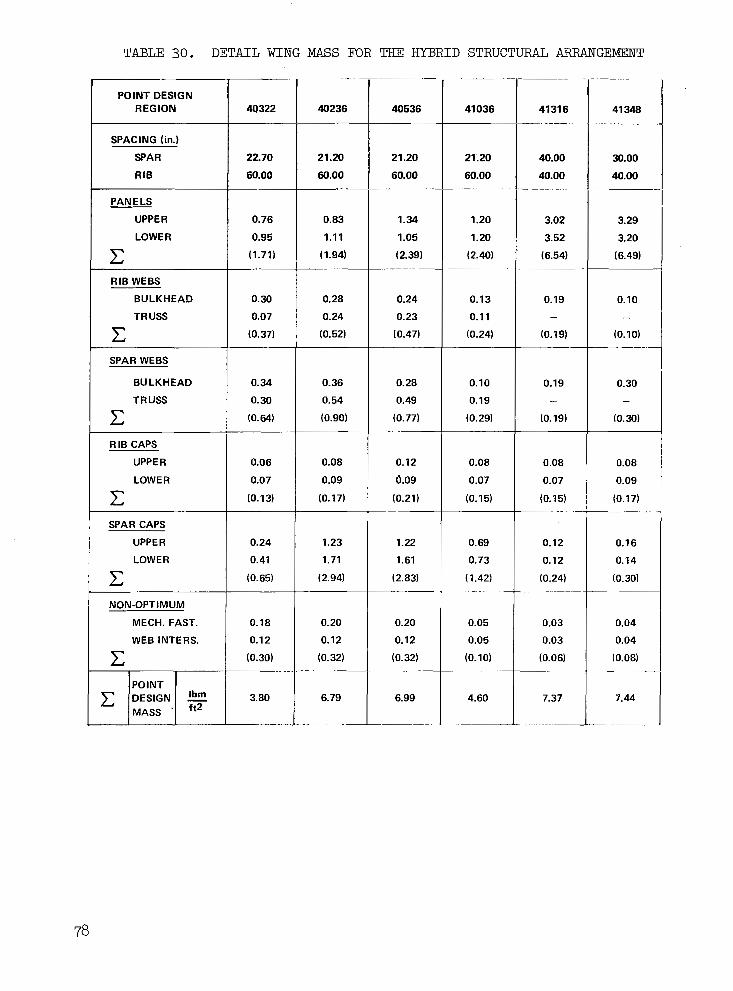
TABLE 30. DETAIL WING MASS FOR THE HYBRID STRUCTURAL A R W G E 2 4 3 N T
I
POINT DESIGN REGION
SPACING (in.)
SPAR
RIB
PAN E LS
UPPER
LOWER
c RIB WEBS
BULKHEAD
TR USS
c ~
SPAR WEBS
BULKHEAD
TRUSS
c R IB CAPS
UPPER
LOW E R
c SPAR CAPS
UPPER
LOWER
c NON-OPTIMUM
MECH. FAST.
WEB INTERS.
POINT
MASS . ft2
40322
22.70
60.00
0.76
0.95
(1.71)
0.30
0.07
(0.37)
0.34
0.30
(0.64)
0.06
0.07
(0.13)
0.24
0.41
(0.65)
0.18
0.1 2
(0.30)
3.80
____
~~ ~"
40236
21.20
60.00
0.83
1.11
(1.94)
0.28
0.24
(0.52)
0.36
0.54
(0.90)
0.08
0.09
(0.17)
1.23
1.71
(2.94)
0.20
0.12
(0.32) ._____
6.79
__ "
40536
21.20
60.00 ____
1.34
1.05
( 2.39)
0.24
0.23
(0.47)
0.28
0.49
(0.77)
0.12
Q.09
(0.21)
1.22
1.61
(2.83)
0.20
0.12
(0.32) ~ -
6.99
_ _ _ - ~
41036
21:20
60.00 _ _ _ ~
1.20
1.20
(2.40)
0.13
0.11
(0.24)
0.10
0.19
(0.29)
0.08
0.07
(0.15)
0.69
0.73
(1.42)
0.05
0.05
(0.10) ~-
4.60
-~
41 31 6 " "_
40.00
40.00 -
3.02
3.52
(6.54)
0.19 -
(0.19)
0.19 -
(0.19)
0.08
0.07
(0.15)
0.12
0.12
(0.24) ~"
0.03
0.03
(0.06)
7.37
__
41 348 .~ ~
30.00
40.00
3.29
3.20
(6.49)
0.10 -
(0.10) -~
0.30 -
(0.30)
0.08
0.09
(0.17)
0.16
0.14
(0.30) ~~
0.04
0.04
(0.08)
7.44
"
TABLE 30. DETAIL WING MASS FOR THE HYBRID STRUCTURAL ARRANGEMENT ( C o n t i n u e d )
~-
POINT DESIGN REGION
~ ~~~~ ~~
SPACING (m)
SPAR
RIB [?LR ~~
E;: RIB WEBS
BULKHEAD
TR U S
~~
RIB CAPS
UPPER
LOWER
c I SPAR CAPS
UPPER
LOWER
c I c NON-OPTIMUM
MECH. FAST.
WEB INTERS.
40322
0.571
1.521 ~~
3.71
4.64
(8.35)
1.46
0.34
(1.80)
1.66
1.46
(3.1 2)
0.29
0.34
(0.63)
1.17
2.00
(3.17)
0.88
0.59
(1.47)
18.55
~~~~ ~~
40236
0.577
1.524 ~~~~
~ ~~
4.05
5.42
(9.47)
1.37
1.17
(2.54)
1.75
2.64
(4.39)
0.39
0.44
(0.83)
6.00
8.35
(14.35)
0.98
0.59
(1.57)
33.15
40536
0.577
1.524 ~-
6.54
5.13
(1 1.67)
1.17
1.12
(2.29)
1.37
2.39
(3.76)
0.59
0.44
(1.03)
5.96
7.86
(13.82)
0.98
0.59
(1.57)
34.13
41036
0.577
1.524
5.86
5.86
(11.72)
0.63
0.54
(1.17)
0.49
0.93
(1.42)
0.39
0.34
(0.73)
3.37
3.56
(6.93)
0.24
0.24
(0.48)
22.46
41316
1.016
1.016
14.74
17.19
(31.93)
0.93 -
(0.93)
0.93 -
(0.93)
0.39
0.34
(0.73)
0.59
0.59
(1.18)
0.15
0.15
(0.30)
35.98
41 348
0.762
1.016
16.06
15.62
(31.68)
0.49 -
(0.49)
1.46 -
( 1.46)
0.39
0.44
(0.83)
0.78
0.68
(1.46)
0.20
0.20
(0.40)
36.33
79
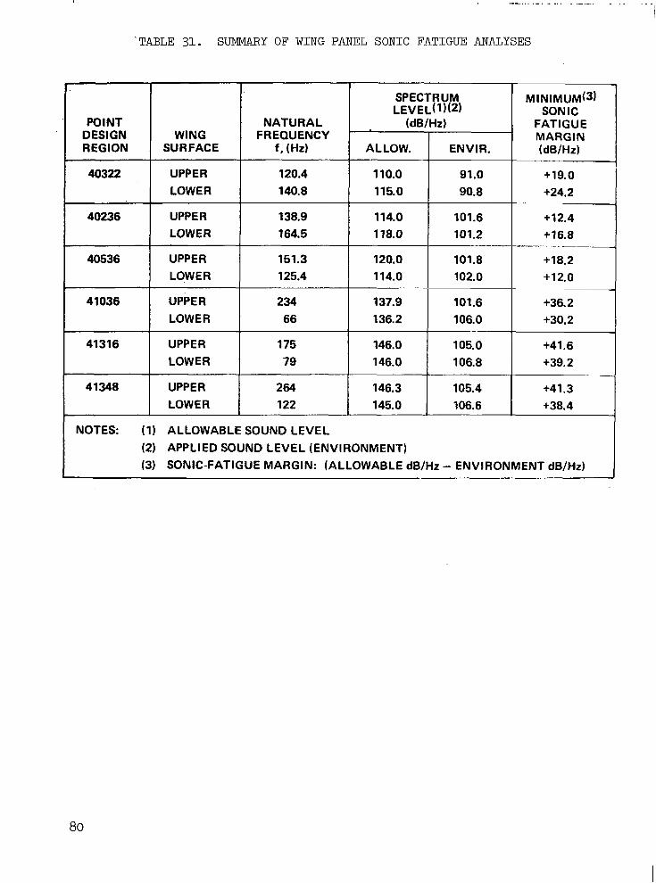
.. . .- . .. .. . . . . . . . .
'TABLE 31. SUMMARY OF WING PANEL SONIC FATIGUE ANALYSES
(3) SONIC-FATIGUE MARGIN: (ALLOWABLE dB/Hz - ENVIRONMENT dB/Hz)
80
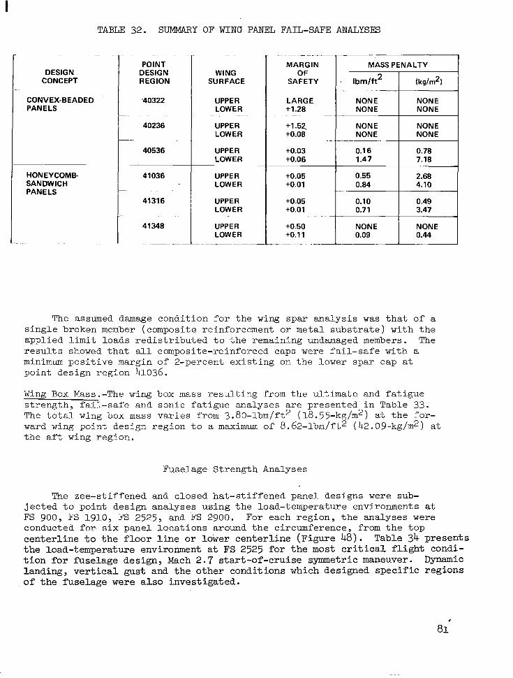
TABLE 32. SUMMARY OF WING PANEL FAIL-SAFE ANALYSES
DESIGN CONCEPT
CONVEX-BEADED PANELS
HONEYCOMB- SANDWICH PANELS
" ~ ~
POINT DESIGN REGION
'40322 ~~~ .
40236 -
40536
41036 . . .
41316
41 348
~
~~
WING SURFACE
UPPER LOW E R
UPPER LOWER
UPPER LOWER
UPPER LOW E R
UPPER LOW E R
UPPER LOWER
~. .
~~
-~
MARGIN MASS PENALTY OF
SAFETY
LARGE
(kg/m2) . Ibrn/ft2
0.44 0.09 +O.ll NONE NONE +0.50
3.47 0.71 +0.01 0.49 0.10 +0.05
4.10 0.84 +0.01 2.68 0.55 +0.05
7.18 1.47 +0.06 0.78 0.1 6 +0.03
NONE NONE +0.08 NONE NONE +1.52,
NONE NONE +1.28 NONE NONE
.. ~ ~
. -~
.
." .
-~ ~ ."
The assumed damage condi t ion for the w i n g spar analysis w a s t ha t o f a single broken member (composite reinforcement or metal substrate) with the applied l i m i t loads redistributed to the remaining undamaged members. The r e s u l t s showed t h a t all composite-reinforced caps were fa i l - sa fe wi th a minimum positive margin of 2-percent existing on the lower spar cap a t point design region 41036.
Wing Box Mass.-The wing box mass resu l t ing from the u l t imate and fa t igue s t rength, fa i l -safe and sonic fatigue analyses are presented in Table 33. The t o t a l wing box mass var ies from 3.80-lbm/ft2 (18.55-kg/m2) a t the for - ward wing point design region t o a maximum of 8.62-1bm/ft2 (42 .09-kg/m2) a t t h e a f t wing region.
Fuselage Strength Analyses
The zee-stiffened and closed hat-st iffened panel designs were sub- jected to point design analyses using the load-temperature environments at FS 900, FS 1910, FS 2525, and FS 2900. For each region, the analyses were conducted for. s ix panel locations around the circumference, from the t op centerline t o t h e floor l i n e or lower centerline (Figure 48). Table 34 presents the load-temperature environment a t FS 2525 for t h e most c r i t i ca l f l igh t condi - t i o n for f'uselage design, Mach 2.7 s tar t -of-cruise symmetric maneuver. Dynamic landing , ver t ica l gust and the other conditions which designed specific regions of the fuse lage were also investigated.

TABLE 33. WING BOX MASS FOR POINT DESIGN REGIONS
POINT STRENGTH SONIC FATIGUE DESIGN I FA1 L-SAFE
Ibrn/ft2 (kg/rn2) REGION
TOTAL
40322 3.80 0.00 0.00 '3.80 (18.55)
(33.15) lO.00) (0.00) (33.15) 6.79 0.00 0.00 6.79 40236
(18.55) (0.00) (0.001
. ~~~~ .
-
_. .~ __ 40536 1.63 0.00 6.99
(34.13)
(22.46) (0.00) (6.78) l~ (29.24) ""1 41316 8.18 0.81 7.37
(36.33) 7.53 0.09 0.00 7.44 41348
(39.94) - (3.96) (0.00) (35.98) 0.00
4.60T- Oao0 1 (0.00) (42.09) (7.96)
" . " 8m62 1 41 036 1.39
. ~ ~~ ~~
~~~
I (0.00) (36.77) (0.44)
I I
FS 2900
i I I p/\ ........
.... I k::::.l .....
FS 1910 /
I
Figure 48. Fuse lage Pane l Iden t i f i ca t ion
82
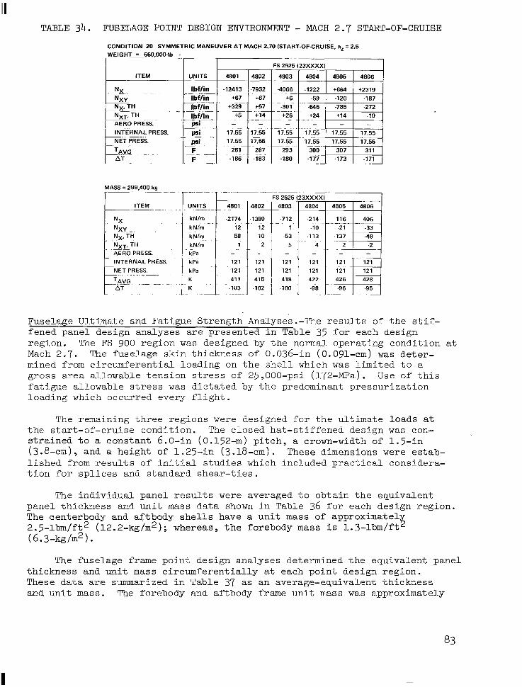
TABLE 34. FUSELAGE POINT DESIGN ENVIRONMENT - MACH 2.7 START-OF-CRUISE
CONDITION 20 SYMMETRIC MANEUVER AT MACH 2.70 (START-OF-CRUISE, nz = 2.5 WEIGHT = 660,000-lb .
ITEM
FS 2525 (23XXXX)
" ~-
UNITS 4801 4802 4803 4804 4805 4806 I I I I
INTERNAL PRESS.
MASS = 299,400 kg I----- r- T "
-1389 12 10 2 -
121 121
415 -102 ~ ~~
. .. 5 4
~ . .
Fuselage Ultimate and Fatigue Strength Analyses.-The results of the s t i f - fened panel design analyses are p r e s e n t e d i n T a b l e 35 for each des ign reg ion . The FS 900 reg ion w a s designed by t h e normal operat ing condi t ion a t Mach 2.7. The fuselage skin thickness of 0 .036-in (0.091-em) was de te r - mined from c i r cumfe ren t i a l l oad ing on t h e s h e l l which w a s l i m i t e d t o a gross a rea a l lowable t ens ion s t ress o f 25 ,000-ps i ( l72-MPa) . Use o f t h i s f a t i g u e a l l o w a b l e s t r e s s w a s d i c t a t e d by t h e predominant pressurization loading which occur red every f l igh t .
The remaining three regions were designed for the ul t imate loads a t the s t a r t -o f - c ru i se cond i t ion . The c losed ha t - s t i f f ened des ign was con- s t r a i n e d t o a constant 6 .0- in (0.152-m) p i t c h , a crown-width of 1 .5- in (3.8-cm), and a he ight of 1.25-in (3.18-em). These dimensions were estab- l i s h e d from r e s u l t s o f i n i t i a l s t u d i e s which included pract ical considera- t i o n f o r s p l i c e s and s tandard shear - t ies .
The i n d i v i d u a l p a n e l r e s u l t s were averaged t o o b t a i n t h e e q u i v a l e n t pane l t h i ckness and un i t mass d a t a shown in Tab le 36 for each des ign reg ion . The centerbody and af tbody shel ls have a u n i t mass of approximate1 2.5-lbm/ft2 (12.2-kg/m2); whereas, the forebody mass i s 1.3-lbm/ft ?i (6.3-kg/m2).
The fuse l age frame point design analyses determined the equivalent panel thickness and uni t mass c i r cumfe ren t i a l ly a t each point design region. These data are summarized i n T a b l e 37 as an average-equivalent thickness and un i t mass. The forebody and aftbody frame unit mass w a s approximately
I
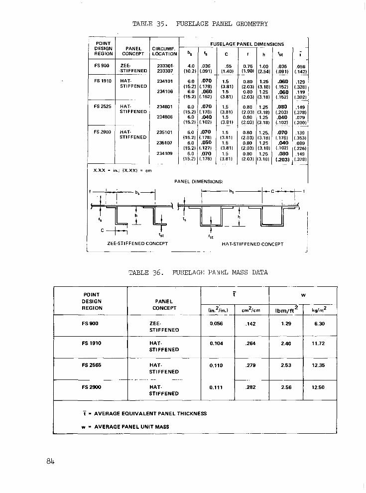
TABLE 35. FUSELAGE PANEL GEOMETRY
POINT DESIGN REGION
FS 900
FS 1910
FS 2525
FS 2900
CONCEPT PANEL
ZE E- .STIFFENED _ _ _ _ HAT- STIFFENED
_ _ ~ ~
HAT- STIFFENED
~
STIFFENED HAT-
CIRCUMF. LOCATION
233301- 233307
234101
234106
234801
234806
235101
2351 07
234 109
-
T - b5
(10.2) 4.0
(15.2) 6.0
(15.2) 6.0
(15.2) 6.0
(15.2) 6.0
(15.2) 6.0
(15.2) 6.0
(15.2) 6.0
F - 'r
(.091)
.070 (.178)
(.152) .NO
l.178) .070
( . l o a .040
.070 (.178) .050
(.127)
(.178) .070
.036
ELAGE
C
~
(1.40) .55
(3.81) 1.5
(3.81) 1.5
(3.81 1.5
(3.81) 1.5
1.5 (3.81 1 1.5 (3.811 1.5
(3.81)
~
~
ANEL
f
~
0.75 ( 1 .go)
0.80 (2.03) 0.80
(2.03)
0.80 (2.03) 0.80
(2.03)
(2.03) 0.80
(2.03) 0.80
(2.03) 0.80
-
IMENSIONS ~~
h
(2.541 1 .oo
(3.181 1.25
13.18) 1.25
:3.181 1.25
13.18) 1.25
13.181 1.25.
(3.181 1.25
3.18) 1.25
'rt - t
(.091)
(.353 (.178)
,078 .040 (.20C (.lo21
.14f .080 (.37€ (.2031
,115 .060 (.30i (.1521
.12E .060 (.32E (.152)
.05f .036 (.14;
.070 ,139
.&lo ,088
.080 .149 (.203) (.37E
.~
. _
- . . . . . - . - -
(.lo21 (.22€
" ~ 1 X.XX = in.; (X.XX) = cm
PANEL DIMENSIONS:
h I
t t 5 t t S t
!
ZEE-STIFFENED CONCEPT HAT-STIFFENED CONCEPT I I
TABLE 36. FUSELAGE PANEL MASS DATA
POINT DESIGN
CONCEPT REGION PANEL
(in.2/in.) crn2/cm Ibm/ft * 6.30 1.29 .142 0.056 ZEE- FS 900
kg/m2
- t W
STIFFENED - FS 1910 11.72 2.40 .264 0.104 HAT-
STIFFENED
FS 2565 12.35 2.53 .279 0.110 HAT- STIFFENED
FS 2900 12.50 2.56 .282 0.111 HAT- STIFFENED
- t = AVERAGE EQUIVALENT PANEL THICKNESS
w = AVERAGE PANEL UNIT MASS

TABLE 37. SUMMARY OF FRAME GEOMETRY AND MASS
I
POINT DESIGN REGION ._ .
FS 900
FS 1910
FS 2525
FS 2900
I FUSELAGE FRAME PROPERTIES I
~ ~"
FRAME SPACING, b AREA, A
(in,.)
21.21
23.23
21.25
21.00
".
53.87 0.197
59.00 0.465
53.98 0.474
(cm 1 2
1.27
3.00
3.06
~
1.15
A = AVERAGE FRAME AREA. inL OR cm2
- t W
I 1 -
(in2/in)
0.98 0.20 0.02 16 0.0085
2.49 0.51 0.0566 0.0223
2.25 0.46 0.0508 0.0200
1.02 0.21 0.0236 0.0093
(kdm2) (Ibm/ft2) (cm2/cm) ~~ ~.
Y
= 2 CiAi Ci I" ci = CIRCUMFERENTIAL LENGTH OF ith ELEMENT, in OR cm
i-1 i= 1 Ai = FRAME AREA OF ithELEMENT, in2 OR cm2
- t = EQUIVALENT SURFACE PANEL THICKNESS, in2/in. OR cm2/cm
= A/b
w = EQUIVALENT SURFACE PANEL WEIGHT, Ibm/ft2 OR kg/m2 ~~ _ _ ~~~
0.2O-lbm/ft (0.98-kg/m ) ; the centerbody frame unit mass w a s approximately 0. 50-lbm/ft2 ( 2.44-kg/m2) .
2 2
Fuselage Sonic Fatigue Analyses.-Table 38 summarizes t h e r e s u l t s of t h e fuse lage sonic , fa t igue ana lyses . Pane l in format ion , na tura l f requencies , spectrum levels, and sonic fa t igue margins are displayed. The minimum margin of +9.8dB/Hz r e s u l t e d on t h e s i d e p a n e l a t FS 2900.
Fuselage Fail-safe Analyses.-Table 39 summarizes t h e results of the fuse lage fail-safe ana lyses . This t ab le p resents a summary of the data der ived f rom the de t a i l c a l cu la t ions , i nd ica t e s t he marg in -o f - sa fe ty and mass penal ty a s soc ia t ed w i th t he spec i f i c pane l s , and the average m a s s p e n a l t y f o r t h e en t i re po in t des ign reg ion . All r eg ions r equ i r ed add i t iona l s t ruc u re t o meet the f a i l - s a fe r equ i r emen t s . The highest penal-ty, 0.46-lbm/ft (2.24- kg/m2) w a s a s soc ia t ed w i th t he midbody region a t FS 2525; the a f tbody region at FS 2900 exh ib i t ed t he h ighes t f a i l - s a fe capab i l i t y , i . e . , l owes t pena l ty , a t 0. 10-lbm/ft2 ( 0. 49-kg/m2 ) .
3
Se lec t ive pane l s t i f f en ing w a s r e q u i r e d t o meet t he c i r cumfe ren t i a l c rack c r i te r ia ; whereas , a l l reg ions requi red c i rcumferent ia l fail-safe s t r a p s t o a t t a i n t h e l o n g i t u d i n a l c r a c k c r i t e r i a .
Fuselage She1L'Mass.-The r e s u l t s o f t h e ultimate and fatigue s t r eng th , fail-safe and sonic fa t igue ana lyses were combined t o e s t a b l i s h t h e f u s e - l a g e u n i t mass a t each point design region. Table 40 summarizes these results. The fuse l age un i t mass varies from 1.75-lbm/ft2 ( 8.54-kg/m2) i n

TABLE 38. SUMMARY OF FUSELAGE SONIC FATIGUE ANALYSES -
POINT DESIGN REGION
FS 900
FS 1910
FS 2525
FS 2900
NOTES:
CONCEPT PAN EL
ZEE- STIFFENED
HAT- STIFFENED
HAT- STIFFENED
HAT- STIFFENED
LOCATION
TOP SIDE BOTTOM
TOP SIDE
TOP SI DE
TOP SIDE BOTTOM
NATURAL FREQUENCY
f. (Hz)
245.0 245.0 245.0
(dB/I
ALLOW.
121.0 121.0 121.0
255.0 131.0 255.0 130.5
350.0 134.0 330.0 128.0
340.0 300.0 350.0
132.0 126.0 134.0
_ _ _ _ ..
(1) ALLOWABLE SOUND LEVEL
(2) APPLIED SOUND LEVEL (ENVIRONMENT)
FATIGU MARGll (dB/Hzl
+37.0 +37.0 +37.0
+39.0 +38.5
+34.6 +28.4
116.2 +15.8 116.2 +9.8 116.1 +17.9
(3) SONIC-FATIGUE MARGIN = (ALLOWABLE dB/Hz - ENVIRONMENT dB/Hz)
CONCEPT
ZEE-STIFF.
HAT4TIFF. CONCEPT
CONCEPT HAT-STIFF.
Li HAT-STIFF.
DESIGN POINT
PANEL TYPE OF REGION LOCATION CRACK
FS900 TOP SIDE ClRCUM
CIRCUM
TOP LONG SIDE LONG
"
FS 1910 TOP CIRCUM SIDE CIRCUM
FS2525 TOP CIRCUM SIDE CIRCUM
TOP . LONG SIDE LONG
~ ~" ~
FS 2900
BOTTOM SIDE
CIRCUM TOP CIRCUM CIRCUM
TOP LONG SIDE LONG BOTTOM LONG
I I NOTES:
PANEL MASS PENALTY
A'i = A;PANEL + A ~ ~ ~ ~ ~ l b
Awi = 144pATi
T
I _________~ ~. ~~
MARGIN
SAFETY OF
+1.25 +HIGH ~
M.01 +0.01
+0.51 +2.11
+0.46 +0.02
+0.74 +0.01
+0.52 +1.18
+1.27 +1.11 +0.25
+0.50
+0.44 C0.04
~
1 MASS PENALTY (AW, . ." "
t F
Ibm/ft -~
NONE
-NONE 0.25 0.25
NONE NONE
0.06 0.15
NONE
~
2.34
0.06 0.06
NONE NONE
NONE
0.07 0.22 0.07
~
~ I EL
kg/rn2 ~
NONE NONE
1.22 1.22
NONE N O N E
0.29 0.73
-
NONE 11.42
0.29 0.29
NONE NONE NONE
0.34
0.34 1.07
" -
~-
I POINT DESIGN
REGION -
0.25 I bm/ft*
(1.22 kglrn')
-
0.22 Ibm/ft2
(1.07 kdrn2I
-
0.46 Ibrn/ft2
(2.24 kglrn'j
I 0.10 I bm/ft2
(0.49 kglrn')
POINT DESIGN REGION MASS PENALTY
ATAvG. = Xc,Aii/Xci
Aw = l44pATAvG.
I WHERE: ATi = EQUIVALENT SURFACE PANEL THICKNESS OF i t h PANEL
ATAvG = AVERAGE SURFACE PANEL THICKNESS OF FUSELAGE CROSS-SECTION
ci = CIRCUMFERENCE OF i* SURFACE PANEL
= ADDITIONAL THICKNESS OF ith PANEL FOR FAIL-SAFE
A~~~~~ = STRAP AREA OF it'' PANEL FOR FAIL.SAFE
b = FRAMESPACING
86
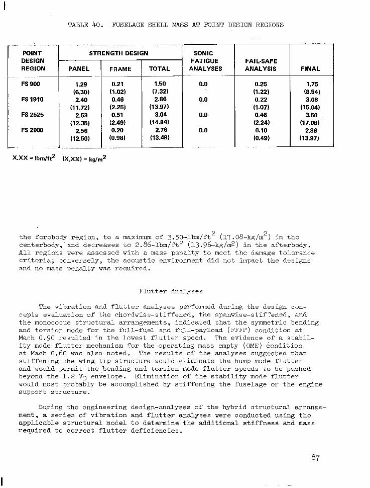
I TABLE 40. FUSELAGE SHELL MASS AT POINT DESIGN REGIONS
POINT STRENGTH DESIGN 1 DESIGN REGION
FS 900
FS 1910
FS 2525
FS 2900
"
X.XX = Ibrn/ft2
(1.02)
(1 1.72)' (2.25) 2.53
(12.35) (2.49) 2.56. 0.20
(12.50) (0.98) . ~~
(x,XX) = kg/rn2
TOTAL ~
1.50 (7.32) 2.86
(13.97) 3.04
(14.84) 2.76
(13.48)
SONIC FATIGUE
ANALYSES
0.0 . .
0.0
0.0-
0.0
~ I FAIL-SAFE
ANALYSIS
0.25 (1.22) 0.22 (1.07) 0.46 (2.24) 0.10 (0.49)
FINAL
1.75 (8.54) 3.08
(15.04) 3.50
(17.08) 2.86
(1 3.97)
the forebody reg ion , to a maximum of 3. 50-lbm/ft2 (17.08-kg/m ) i n t h e cen te rbody , . and dec reases t o 2 .86 - lbm/ f t2 (13.96-kg/m2) i n t h e a f t e r b o d y . All regions were assessed with a mass p e n a l t y t o meet t h e damage t o l e r a n c e c r i te r ia ; converse ly , the acous t ic envi ronment d id no t impact the des igns and no mass pena l ty w a s requi red .
2
F lu t te r Analyses
The v i b r a t i o n and f lu t t e r ana lyses pe r fo rmed du r ing t he des ign con- cepts eva lua t ion of the chordwise-s t i f fened , the spanwise-s t i f fened , and t h e monocoque s t ruc tura l a r rangements , ind ica ted tha t the symmetr ic bending and t o r s i o n mode f o r t h e f u l l - f u e l and ful l -payload (FFFP) condi t ion a t Mach 0 .90 r e su l t ed i n t he l owes t f l u t t e r speed . The evidence of a s t a b i l - i t y mode f l u t t e r mechanism f o r t h e o p e r a t i n g mass empty ( O M E ) condi t ion a t Mach 0.60 w a s a l so no ted . The r e s u l t s of t he ana lyses sugges t ed t ha t s t i f f e n i n g t h e wing t i p s t r u c t u r e would e l i m i n a t e t h e hump mode f l u t t e r and would permit t he bend ing and t o r s ion mode f l u t t e r s p e e d s t o b e p u s h e d beyond t h e 1 . 2 VD enSelope. El iminat ion of t h e s t a b i l i t y mode f l u t t e r would most probably be accomplished by s t i f fening the fuselage or the engine suppor t s t ruc tu re .
During the engineer ing design-analyses of t h e h y b r i d s t r u c t u r a l a r r a n g e - ment, a series of v i b r a t i o n a n d f l u t t e r analyses were conducted us ing the a p p l i c a b l e s t r u c t u r a l model t o de t e rmine t he add i t iona l s t i f fnes s and mass r e q u i r e d t o c o r r e c t f l u t t e r d e f i c i e n c i e s .

" . ... " , . . .- . "-
Symmetric vibration analyses of the hybrid design were conducted for the operating empty mass (OEM) and the full-fuel and full-payload (FFFP) conditions. A summary of the lower frequency symmetric vibration modes and frequencies for the final design airplane is presented in Table 41.
Symmetric flutter analyses were first performed at Mach 0.90 for both the OEM and FFFE! conditions using the strength-designed model. The flutter solutions indicated that the flutter speed was.insensitive to fuel and pay- load, and that a flutter deficiency still existed for the strength-designed hybrid concept for the symmetric bending and torsion mode (Figure 49). A flutter optimization, focused on the wing tip region, was conducted to eliminate the deficiency. This resulted in the addition of 1201-lbm (545-kg) of structural mass to each wing tip. The element properties of the structural model were altered to reflect this change.
Symmetric and antisymmetric flutter analyses were then conducted for both the OEM and FFFP conditions at Mach 0.90, and for the OEM condition at Mach 0.60 and 1.85. The results of these analyses are shown on Figure 50 for the bending and torsion mode and the stability mode. The more than necessary increase in the flutter speed at Mach 0 . 9 was primarily due to imposing design and manufacturing considerations on the stiffening requirements indicated by the flutter optimization. An additional small portion, 5-keas, was attributed to the assumption in the optimization of linear stiffness variation for the design variables.
Flutter deficiencies were indicated (Figure 50) at Mach numbers of 0.60 and 1.85. At Mach 0.60, the stability mode was critical. The GFAM (interactive computer graphics) flutter optimization program was used to investigate the effectiveness of adding bending stiffness to the fuse- lage, and to the inner and outer engine support beams (Figure 51). Contrary to the preliminary indications, fuselage stiffening did not increase the flutter speed. The optimization solution resulted in increasing the bend- ing stiffness of the aft portion of the inboard engine support beam. This increase in bending stiffness was obtained with no mass penalty through use of boron-aluminum reinforcement for the support beam.
The critical flutter mode at Mach 1.85 was the bending and torsion mode. To correct this deficiency, flutter optimization was conducted on the wing tip structure at Mach 1.85 to determine the required increases in stiffness and mass. This resulted in a further addition of 599-lbm (272-kg) of structural mass to each wing tip. The final thicknesses for the wing tip surface panels and spar webs are shown in Figure 52. Figure 53 displays the effects of the wing tip stiffening at the Mach 0.90 and 0.60 conditions resulting from the aforementioned analysis. A summary of the critical mass and boundary conditions, flutter mechanisms and speeds, and the associated mass penalties to attain 1.2 V are shown in Table 42. D
Rol l Control Effectiveness
Reversal speeds and FAR requirements were compared f o r both the normal scheduled surface combinations, and for selected fail-safe conditions which involved the loss of a surface which has the most adverse effect on roll-control reversal speed. The primary surfaces used for roll control
aa

TABLE 41. LOWER FREQUENCY SYMMETRIC VIBRATION MODES - FINAL DESIGN
MODE FREQUENCY Hertz
MODE DESCRIPTION
3.174 3.694 WING IST TORSION
2.478 3.025 FUSELAGE 2ND BENDING
1.735 1.752 ENGINE PITCH OUT OF PHASE
1.494 1.499 ENGINE PITCH IN PHASE
1.345 1.645 FUSELAGE IST BENDING
0.915 0.996 WING IST BENDING
0.000 0.000 RIGID BODY
0.000 0.000 RIGID BODY
FFFP O E M . "" ~ ~
~- .
. " ~ ~~ ~~ ~~
~~ ~ _ _ _ _ _ _
" -~
~~~
~~ ~
OEM - AIRPLANE MASS = 314,000 Ibrn (142,400 kg) FFFP - AIRPLANE MASS = 750,000 Ibrn (340,000 kg)
24
20
16
E
I
12 3
w 8 n t 3
I- J 4 a
0
-4
-8
0 100 200 300 400 500 600 700 800 900 VELOCITY -keas
I I I I I I I I 0
I 200 400 600 800 1000 1200 1400 1600
VELOCITY - km/h
Figure 49. F lu t te r Speeds for Symmetric Bending and Torsion Mode - Strength Design
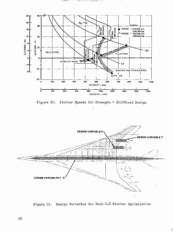
. ." - "" . . . . .. . . . . .... . . "_
24 -
20 - 60
16 -
12 - 40
E 1 e - I
Y c "- Y O
Y
3
E I - 4 - 5 20 t
a a -I A
0 - 0
-4 - -20
-8 L
-40 0 100 200 300 400 500 600 700 800 900 1000
VELOCITY -keas
I I I I I I I I I I 0 200 400 600 800 1000 1200 1400 1600 1800
VELOCITY - km/h
Figure 50. F l u t t e r Speeds for St reng th + St i f fnes s Des ign
DESIGN VARIABLE 6
DESIGN VARIABLE 7
"
\
DESIGN VARIABLES 1 - 5

@ DESIGN VARIABLES
(a) . Design Variables
REAR ~~~ ~. .
FRONT BEAM 0.200 BEr
(0.508)
0.160 (0.406)
0.160 (0.406) ~
0m17O (0.4831 (0.432)
0.190 (0.660)
SECTION AA
RB
RB
FB
(0.533)
SECTION CC
RB
I 0.174 I
0.200 (0.508)
FB 0.210 1 0.200 0.125 (0.508) (0.318)
0.200 0.1 25 (0.508) (0.318) 0.1 74
0.210 (0.610) (0.533)
(0.442)
SECTION BB SECTION DD
NOTE: .x i n ( .XXX 4 ( b ) . Surface Panel and Web Thickness
Figure 52. Mach 1.85 Flutter Optimization
91
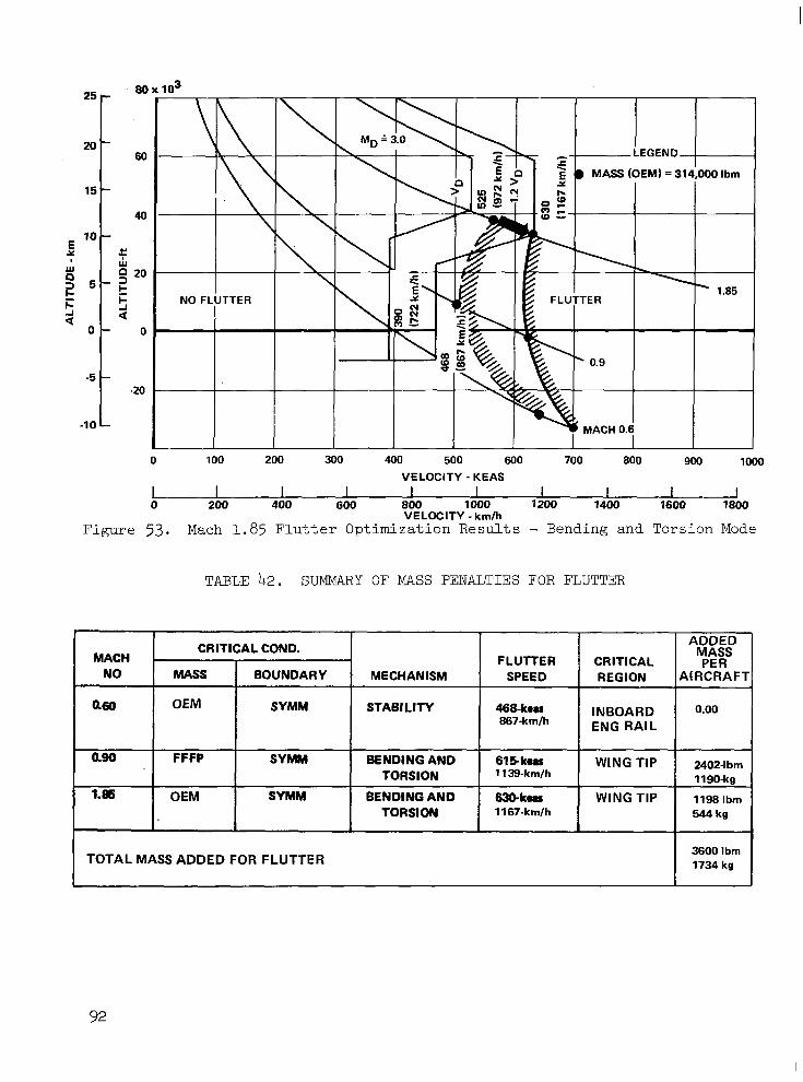
25- 80
20 - 60
15 - 40
E 10 -
x 2 x 5 -
2 20
z 5 5 t
-3 a 0 - 0
-5 - -20
-10 -
NO FI
0 100 200 300 400 500 600 700 800 900 loo0
I I 1 I I 1 I I I I VELOCITY -KEAS
0 200 400 600 800 1000 1200 1400 1600 1800 VELOCITY - kmlh
Figure 53. Mach 1.85 Flutter Optimization Results - Bending and Torsion Mode
TABLE 42. SUMMARY OF MASS PENALTIES FOR FLUTTER
CRITICAL COND. ADDED MASS PER MACH CRITICAL FLUlTER
NO AIRCRAFT REGION SPEED . MECHANISM BOUNDARY MASS
a60 460-hu STABILITY SYMM OEM INBOARD 0.00
ENG RAIL 867-kmlh
am
1.86
615koa BENDING AND SYMM FFFP WING TIP 2402-lbm
OEM 1198 Ibm WING TIP 63Gkma BENDING AND SYMM TORSION 1139-km/h 1190-kg
1 I. I I TORSION I 1167-kmlh I I 544kg I
I TOTAL MASS ADDED FOR FLUTTER
92

I
I at t h e v a r i o u s o p e r a t i o n a l Mach numbers f o r t h i s a n a l y s i s are shown i n F i g u r e , 54. The subsonic roll c o n t r o l was obta ined by use of t h e wing trail- ing edge panels (No. 2 through No. 4 ) with the low speed a i leron locked-out above Mach 0.40 o r 260-keas (482-km/h). For supersonic roll c o n t r o l , t h e s p o i l e r - s l o t d e f l e c t o r a t No. 2 and t he i nve r t ed spo i l - e r - s lo t de f l ec to r a t NO. 3 were used . In a l l c a s e s , t h e f i n a l des ign a i rp lane exceeded the spec i f ied requi rement .
F igu re 55 'p re sen t s a measure of roll c a p a b i l i t y o f t h e f i n a l d e s i g n a i r p l a n e a t supersonic speeds. The results were obtained by executing a one-degree of freedom steady s ta te r o l l u s i n g t h e s p o i l e r - s l o t d e f l e c t o r at No. 2 a n d t h e i n v e r t e d s p o i l e r - s l o t d e f l e c t o r a t No. 3. The r e s u l t s i n d i c a t e a ro l l - ra te capabi l i ty o f 20-degree ( .35 rad) per second at s u p e r s o n i c s p e e d s f o r t h e f l e x i b l e s u p e r s o n i c c r u i s e a i r c r a f t .
FINAL DESIGN AIRPLAJTE
Wing St ruc ture Des ign
A hybr id s t ruc tura l approach w a s used f o r t h e wing design. For t h e inboard wing, a chordwise-s t i f fened s t ruc tura l a r rangement us ing low- p r o f i l e , convex-beaded su r face pane l s of t i t a n i u m a l l o y , Ti-6Al-4V, w a s employed. Submerged t i t an ium spa r caps , r e in fo rced w i th un id i r ec t iona l boron-polyimide composite, were used i n t h e a f t box r eg ion and l oca l areas of the forward box (near the main landing gear w e l l ) . The d e s i g n d e t a i l s for a typ ica l su r f ace pane l and subs t ruc tu re are shown i n Figure 57. With the beaded-skin design, wing bending material i s concen t r a t ed i n t he spa r caps , and the sur face pane ls p r imar i ly t ransmi t the shear and chordwise inplane loads and out-of-plane pressure loads. This surface design a l l e v i a t e s t h e r m a l s t r e s s e s a n d r e d u c e s h e a t t r a n s f e r t o t h e f u e l , i n comparison with a f l a t sk in , s ince on ly a p o r t i o n o f t h e f u e l i s i n d i r e c t c o n t a c t w i t h t h e wing e x t e r n a l s k i n .
Weldbonding was u s e d f o r j o i n i n g t h e i n n e r and ou te r sk ins of t h e surface assembly. The manufacturing l imits f o r t h e s u r f a c e p a n e l s w e r e h e l d t o 1 5 - f t (4.57-m) by 35-ft (10.67-m) . The l eng th l i m i t w a s based on t o o l i n g c o n s i d e r a t i o n s f o r h o t vacuum forming of the sk ins , whi le the wid th l i m i t w a s based on the pos tu la ted s ize o f spotweld ing equipment .
I n l o c a t i n g wing spars in the chordwise-s t i f fened wing area, a mini- mum spacing of 21-in (0.53-m) w a s maintained between constraints such as fue l t ank boundar ies . Wing r i b s p a c i n g w a s a nominal 60-in (1.52-m) bu t w a s modified as r equ i r ed t o su i t geomet r i ca l des ign cons t r a in t s . These dimensions def ine minimum mass conditions which w e r e determined through the s tud ie s i nvo lv ing va r ious spa r and r i b spacing. In the chordwise- s t i f f e n e d a n d t r a n s i t i o n areas, welded truss spars were used except where a s p a r serves as a f u e l t a n k w a l l . A t such locations, spars have welded
93

c PRIMARY ROLL CONTROL
SURFACE
0 LOW SPEED AILERON
0 FLAPERON
0 FLAPERON
0 SPOILERSLOT DEFLECTOR AT NO. 4
0 INVERTED SPOILER-SLOT DEFLECTOR AT NO. 3
0 SPOILER-SLOT DEFLECTOR AT NO. 2
- Wlh
PAP T.E
NC
NO
NC
-
OPERATIONAL MACH NO.
NO. 2 & 4 SPOILER6LOT DEFLECTORS n
NO. 3
T- 1 I
1
0.4 0.8 1
L ."_.... J H I NO. 1 PANEL
A M1.85
Figure 54. Primary Roll Control Schedule
.8
.6
ROLL RATE RADISEC
0-
Figure 5 5 .
40
DEG/SEC R O L L RATE
za
a
60,000 ft ( 1 8,000 m) "
I
SLOT DEFLECTOR 2 SSDP, SPOILER- ISSD3, INVERTED SPOILER-SLOT DEFLECTOR 3
4 ' I I 1 .o 1.4 1.8 2.2 2.6
MACH NUMBER
Supersonic Roll Power
94

-i?___r '21.92) cc-, ' ,5558
FUEL SrRuti. AWPGT. (WING)
SURFACE JOlNTS ?EPRESENTATlVE PANELS
..................... ........................ .................. 5. ;;;;g-${$ INDICATES WING POINT DESIGN REGIONS 4. UNLESS NOTED, ALL METAL IS TISAL4V ANL - EXCEPT
CHORDWISE STIFFENED WING WITH COLIPOSITE 9ElNFORCEO SPAR CAP HONEYCOMB CORE IS TI-3AL-2.5V
3. DIMS IN METER5 (INS.); ANGLES IN RADIANS (DEGREES) ALUMINUM BRAZED
1. 0 INDICATES WING SEGMENT NOTES
A FUEL SURGE SPAR HONEYCOMB SANDWICH
Figure 56. S t ruc tu ra l Arrangement of Final Design Airplane

TIG WELD
\
55 PLIES 00 B/PI w TOTAL t = .302 in (.761 cmi i
.180 in (A67 cm) ALTERNATE
\\ .026 in (.(X6 cm) -1 171.44 in (387 cm) 7
870 (1.52 rad)
25 PLIES 00 B/AL TOTAL t = ,189 in (.480 cm) (TY P)
.070 in (.178 cm) R .90 in (2.29 cm) R .023 in LO58 cm)
DIFFUSION BONDED TO CAP ALTERNATE - ALUM. BRAZED -14 1
1.91 in (2.31 cm) FLAT
SECTION A-A
Figure 57. Structural Details for Chordwise-Stiffened Surfaces
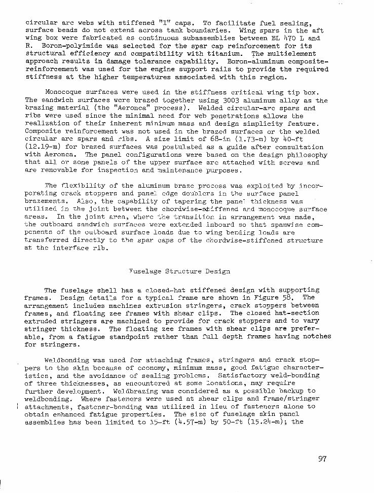
c i r c u l a r a r c webs w i t h s t i f f e n e d "I" caps. To f a c i l i t a t e f u e l s e a l i n g , surface beads do not ex tend across t ank boundar ies . Wing spa r s i n t h e a f t wing box were f a b r i c a t e d as continuous subassemblies between BL 470 L and R. Boron-polyimide was se l ec t ed fo r t he spa r cap r e in fo rcemen t fo r i t s s t r u c t u r a l e f f i c i e n c y a n d c o m p a t i b i l i t y w i t h t i t an ium. The multielement a p p r o a c h r e s u l t s i n damage t o l e r a n c e c a p a b i l i t y . Boron-aluminum composite- re inforcement w a s used f o r the engine suppor t rai ls t o p r o v i d e t h e r e q u i r e d s t i f f n e s s a t the h ighe r t empera tu res a s soc ia t ed w i th t h i s r eg ion .
Monocoque su r faces were u s e d i n t h e s t i f f n e s s c r i t i c a l wing t i p box. The sandwich su r faces were brazed toge ther us ing 3003 aluminum a l l o y as t h e braz ing material ( t h e "Aeronca" p rocess ) . Welded c i r cu la r - a rc spa r s and ribs were used since the minimal need for web p e n e t r a t i o n s a l l o w s t h e r e a l i z a t i o n of t h e i r i n h e r e n t minimum mass and des ign s impl ic i ty fea ture . Composite reinforcement w a s no t u sed i n t he b razed su r f aces or t h e welded c i r c u l a r a r c s p a r s a n d r i b s . A s i z e l i m i t of 68-in (1.73-m) by 40-ft (12.19-m) f o r b r a z e d s u r f a c e s w a s pos tu l a t ed as a g u i d e a f t e r c o n s u l t a t i o n with Aeronca. The panel configurat ions were based on the des ign ph i losophy t h a t a l l o r some panels o f the upper sur face a re a t tached wi th sc rews and are removable for inspect ion and maintenance purposes .
The f l e x i b i l i t y o f t h e aluminum braze p rocess w a s exp lo i t ed by incor- porat ing crack s toppers and panel edge doublers in the surface panel b razemen t s . A l so , t he capab i l i t y o f t ape r ing t he pane l t h i ckness was u t i l i zed i n t he j o in t be tween t he chordwise - sL i f f ened and monocoque su r face a r e a s . I n t h e j o i n t a r e a , where t h e t r a n s i t i o n i n a r r a n g e m e n t w a s made, the outboard sandwich surfaces were extended inboard so that spanwise com- ponents o f the ou tboard sur face loads due t o wing bending loads are t r a n s f e r r e d d i r e c t l y to t h e s p a r caps o f the chordwise-s t i f fened s t ruc ture a t t h e i n t e r f a c e r i b .
Fuselage Structure Design
The f u s e l a g e s h e l l h a s a c losed-ha t s t i f fened des ign wi th suppor t ing frames. Design d e t a i l s f o r a t y p i c a l frame are shown i n F igure 58. The arrangement includes machines extrusion stringers, crack stoppers between frames, and f loat ing zee frames wi th shea r c l i p s . The c losed ha t - sec t ion e x t r u d e d s t r i n g e r s are machined to p rovide for c rack s toppers and to vary s t r i n g e r t h i c k n e s s . The f loa t ing zee frames w i t h s h e a r c l i p s are p r e f e r - a b l e , from a f a t i g u e s t a n d p o i n t r a t h e r t h a n f u l l d e p t h frames having notches f o r s t r i n g e r s .
Weldbonding w a s u s e d f o r a t t a c h i n g frames, s t r i n g e r s and crack s top- p e r s t o t h e s k i n b e c a u s e of economy, minimum mass, good f a t igue cha rac t e r - i s t i c s , and the avoidance of seal ing problems. Sat isfactory weld-bonding o f t h ree t h i cknesses , as encountered a t some l o c a t i o n s , may r e q u i r e further development. Weldbrazing w a s considered as a poss ib le backup to weldbonding. Where f a s t e n e r s were used at shea r c l i p s and f r ame / s t r inge r attachments, fastener-bonding w a s u t i l i z e d i n i i e u o f f a s t e n e r s a l o n e t o obta in enhanced fa t igue p roper t ies . The s i z e o f f u s e l a g e s k i n p a n e l assemblies h a s b e e n l i m i t e d t o 1 5 - f t (4.57-m) by 50-ft (15.24-m); t h e
97
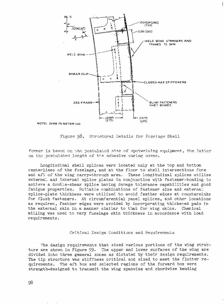
Figure 58. S t r u c t u r a l D e t a i l s f o r F u s e l a g e S h e l l
former i s based on t he pos tu l a t ed s i ze of spo twe ld ing equ ipmen t , t he l a t t e r on the pos tu l a t ed l eng th o f the adhesive curing ovens.
L o n g i t u d i n a l s h e l l s p l i c e s were loca ted on ly a t t h e t o p and bottom c e n t e r l i n e s o f t h e f u s e l a g e , and a t t h e f l o o r t o s h e l l i n t e r s e c t i o n s f o r e and a f t o f t h e wing carry-through area. T h e s e l o n g i t u d i n a l s p l i c e s u t i l i z e ex te rna l and i n t e r n a l s p l i c e p l a t e s i n c o n j u n c t i o n w i t h f a s t e n e r - b o n d i n g t o achieve a double-shear spl ice’having damage t o l e r a n c e c a p a b i l i t i e s and good f a t igue p rope r t i e s . Su i t ab le combina t ions o f f a s t ene r s i ze and e x t e r n a l s p l i c e - p l a t e t h i c k n e s s were u t i l i z e d t o a v o i d f e a t h e r e d g e s a t counters inks f o r f l u s h f a s t e n e r s . A t c i r c u m f e r e n t i a l p a n e l s p l i c e s , and o t h e r l o c a t i o n s as r equ i r ed , f ea the r edges were avoided by incorpora t ing th ickened pads in t h e e x t e r n a l s k i n i n a manner similar t o t h a t f o r wing skins. Chemical m i l l i n g was used t o v a r y f u s e l a g e s k i n t h i c k n e s s i n a c c o r d a n c e w i t h l o a d requirements .
C r i t i c a l Design Conditions and Requirements
The des ign r equ i r emen t s t ha t s i zed va r ious po r t ions o f t he wing s t ruc - t u r e are shown i n F i g u r e 59. The upper and lower surfaces of the wing a r e d i v i d e d i n t o three general zones as d i c t a t e d by t h e i r d e s i g n r e q u i r e m e n t s . The t i p s t r u c t u r e w a s s t i f f n e s s c r i t i c a l and s i z e d t o meet t h e f l u t t e r re- quirements. The a f t box and se l ec t ed r eg ions o f t he fo rward box were s t rength-designed t o t r a n s m i t t h e wing spanwise and chordwise bending

-FOREBODY- -1 = CENTERBODY AFTBODY
STRENGTH DESIGN’
STIFFNESS DESIGN / Figure 59. Critical Design Requirements for t h e Wing St ruc ture

moments and shears . In genera l the forward box s t r u c t u r a l - s i z i n g r e s u l t e d in su r f ace pane l s and subs t ruc tu re components w i t h a c t i v e minimum gage cons t r a in t s . Fo re igh ob jec t ive damage w a s t h e g o v e r n i n g c r i t e r o n f o r s e l e c t i o n of minimum gage. The f u s e l a g e s t r u c t u r e was designed by u l t i m a t e s t r e n g t h and fat igue requirements .
The c r i t i c a l d e s i g n c o n d i t i o n s f o r t h e wing and f u s e l a g e s t r u c t u r e are p resen ted i n F igu re 60. I n g e n e r a l , t h e wing c r i t i c a l d e s i g n c o n d i t i o n s correspond to those conditions which produced the maximum surface-panel loadings. The exception being the wing-tip structure which needed addi- t ion 'a l material t o meet the s t i f fnes s r equ i r emen t d i c t a t ed by t h e Mach 1.85 f l u t t e r c o n d i t i o n . The Mach 1.25 symmetric-maneuver condi t ion was t h e p r e - dominate design condi t ion for the highly loaded af t -box region and port ions of the forward box on both upper and lower surfaces. Conversely, the des ign condi t ion for the wing forward box w a s a s soc ia t ed w i th t he e l eva ted temperature condi t ion a t Mach 2.7. Minimum-gage c o n s t r a i n t s were a c t i v e f o r major por t ions o f th i s reg ion .
The fuselage design w a s inf luenced by the high temperature environ- ment f o r a ma.jor po r t ion o f t he fu se l age uppe r she l l , and f o r t h e p r e s s u r e c r i t i c a l forebody region. The forebody shel l w a s loaded pr inc ipa l ly by fuse l age p re s su r i za t ion , and t h e r e f o r e was c r i t i c a l f o r t h e combined ope ra t iona l l oad and temperature environment at Mach 2.7. The constant ampli tude-type fa t igue loadings imposed upon th i s s t ruc tu re r equ i r ed r educed al lowable tension stresses t o a c h i e v e t h e s e r v i c e l i f e r e q u i r e m e n t s . A s i n d i c a t e d i n t h e f i g u r e , t h e r e m a i n d e r o f t h e f u s e l a g e w a s bending c r i t i c a l . The lower forebody and aftbody structure were c r i t i c a l f o r dynamic landing; the upper forebody for gusts . The centerbody and upper aftbody were c r i t i - c a l f o r combined load and tempera ture e f fec ts .
Final Design Airplane Mass Estimates
Deta i led mass desc r ip t ions of t h e wing and f u s e l a g e a r e p r e s e n t e d i n Tables 43 and 44, r e spec t ive ly . The wing mass desc r ip t ion i nc ludes fa i l - s a fe p rov i s ions , a l l owance fo r f l u t t e r p reven t ion , and panel th ickness changes for manufactur ing/design constraints . The f ixed mass consis ts of those i t ems invar ian t wi th box s t ruc tura l concept , such as con t ro l su r f aces , engine support beams, lead ing and t r a i l i n g edge s t ruc ture .
The fuse lage mass was a l so d iv ided i n to two major ca tegor ies : she l l mass and f ixed mass. Here again t h e s h e l l mass w a s dependent upon s t ruc - tural concept while the f ixed mass such as doors , windows, f l i g h t s t a t i o n and f a i r i n g were i n v a r i a n t . The fuse lage mass shown r e f l e c t s t h e u s e o f the convent ional skin-s t r inger-frame construct ion for the shel l , a l though epoxy resin composites were employed i n s e l e c t e d a r e a s o f t h e i n t e r i o r ( i . e . , f l o o r s , f l o o r beams, and t r i m ) .
The study focused on t h e two l a r g e s t s t r u c t u r a l mass items; t h e wing and the fu se l age , which amounts t o 90,584-lbm (41,088-kg) and 42,122-lbm
100
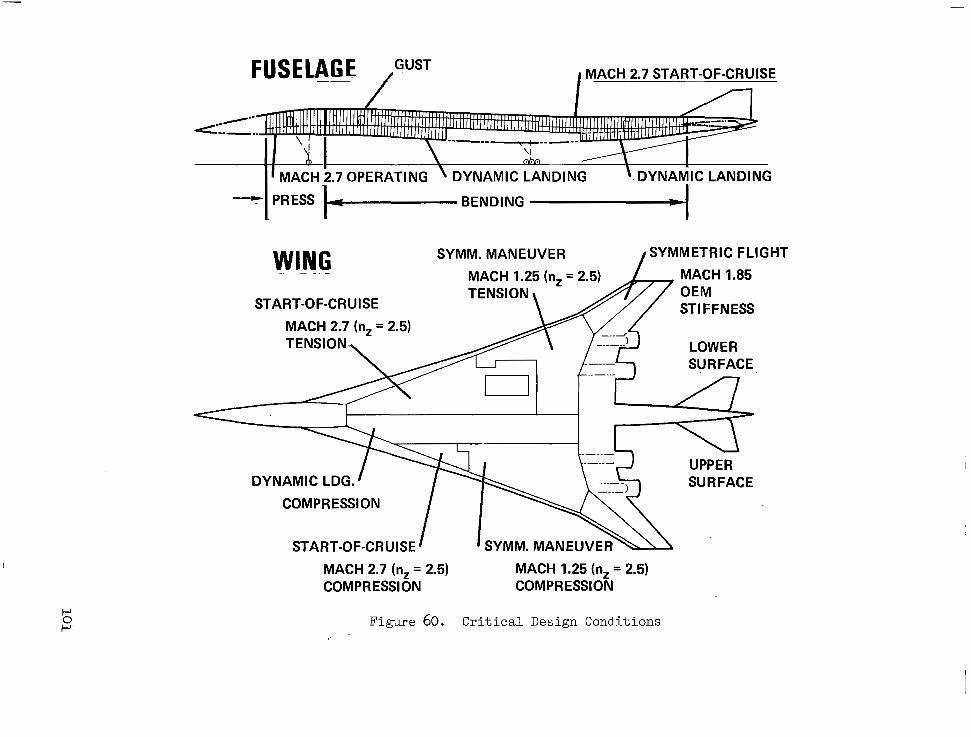
I MACH 2.7 START-OF-CRUISE
- I MACH 2.7 OPERATING \ DYNAMIC LANDING \.DYNAMIC LANDING
PRESS k- BENDING
WING SYMM. MANEUVER SYMMETRIC FLIGHT
MACH 1.25 (n, = 2.5) MACH 1.85 .. " _
START-OF-CRUISE TENSION n
MACH 2.7 (nz = 2.5) TENSION,,
ST1 FFNESS
LOWER \ SURFACE
DYNAMIC LDG. l k - f - 2 UPPER u SURFACE 1
COMPRESSION I I \\\ START-OF-CRUISE ' I SYMM. MANEUVER-
MACH 2.7 (nz = 2.5) MACH 1.25 (nz = 2.5) COMPRESSION COMPRESSION
Figure 60. C r i t i c a l Design Conditions

TABLE 43. MASS ESTIMATES FOR FINAL DESIGN WING
ITEM
VARIABLE MASS
FORWARD BOX 0 SURFACES - CONVEX
BEADED, CHORDWISE STIFFENED
0 SPARS - INCLUDING 522 Ibm (237 kg) COMPOSITES
0 RIBS
AFT BOX 0 SURFACES -CONVEX
BEADED, CHORDWISE STIFFENED
0 SPARS - INCLUDING 3,762 Ibm
0 RIBS (1 706 kg) COMPOSITES
TRANSITION - AFT BOX TO TIP BOX
TIP BOX SURFACES - BRAZED
HONEYCOMB SAND., MECH. FAST.
0 SPARS 0 RIBS
FIXED MASS
LEADING EDGE TRAILING EDGE WING/BODY FAIRING LEADING EDGE FLAPSISLATS TRAILING EDGE FLAPS/
FLAPERONS AILERONS SPOILERS M A I N L A N D I N G
GEAR - DOORS SUP'T. STRUCTURE
B.L. 62 RIBS B.L. 470 RIBS FIN ATTACH RIBS (B.L. 602) REAR SPAR ENGINE SUPPORT
STRUCTURE FUEL BULKHEADS
TOTAL WING MASS
PLANFORM AREA
f t2
4 136.6
2132.4
947
1047 1941 800 133 553
250 225
484
384.3
198.1
88.0
97 180 74 12 51
23 21
45
~
-
MASS
I bm
50,432(A)
(20,580) 9,452
8,558
2,570
(17,384) 7,302
8,568
1,514
(1,380)
(1 1,088) 9,435
1,336 317
40,152
5,235 4,888 1,600 1,130 5,890
1,250 1,360
2,904 3,750 1,430
700 435
3,400 2,380
3,800 -~
90,584
kg
22,876(A)
(9.335) 4,287
3,882
1,166
(7.885) 3,312
3,886
687
(626 1
(5,030) 4,280
606 144
18,213
2,3,5 2.2 17
726 51 3
2.672
567 617
1,317 1,701
649 318 197
1,542 1,080
1,724 - ~- - 41,088
_"
(A) INCLUDES FAIL-SAFE PENALTY OF 822 Ibm (373 kg)
102

TABLE 44. MASS ESTIMATES FOR FINAL DESIGN FUSELAGE
I [TOTAL FUSELAGE MASS
-
ITEM
.
;HELL STRUCTURE
SKIN STIFFENERS FRAMES
-IXED MASS (B) NOSE AND FLIGHT STATION NOSE LANDING GEAR WELL WINDSHIELD AND WINDOWS FLOORING AND SUPPORTS DOORS AND MECHANISM UNDERWING FAIRING CARGO COMPARTMENT PROV. WING TO BODY FRAMES AND FITTINGS TAIL TO BODY FRAMES AND FITTINGS PROV. FOR SYSTEMS FINISH AND SEALANT
~~~ ~ . -~ .- __ -~
MASS
Ibm
22,582(A)
11,144 9,921 3,517
19,540(B) 2,500
900 1,680 3,820 4,170 1,870 1,060 1,500
600 740 700
1 42,122
kg
10,243(A)
5,055 3,593 1,595
8,863(B' 1,134
408 762
1,733 1,891
848 481 680 272 336 318
19,106
(A) INCLUDES FAILSAFE PENALTY OF 1,432 Ibm (650 kg) (B) INCLUDESCOMPOSITE MATERIAL WEIGHT OF
(19,106-kg) , respect ively. These mass items represent 66-percent of t h e t o t a l s t r u c t u r a l mass and abou t 17 .7 -pe rcen t o f t he a i r c ra f t t ax i mass. A more d e t a i l e d l o o k a t t h e mass d i s t r i b u t i o n o f t h e l a r g e s t component, t h e wing , i nd ica t e s t ha t 50,432-lbm (22,876-kg) i s a t t r i b u t e d t o t h e p r i m a r y s t r u c t u r a l box ( i . e . , f o r w a r d , a f t , t i p . a n d t r a n s i t i o n s t r u c t u r e ) . The m a j o r r i b s , rear spa r , fue l bu lkheads , and engine support s t ructure accounts for 12,145-lbm (5,509-kg). The leading-edge and trail ing-edge s t r u c t u r e , s p o i l e r s , wing/body f a i r i n g , and main landing gear doors and suppor t s t ruc ture accounts for the remain ing 28,007-lbm (12,704-kg).
The mass p r o p e r t i e s f o r t h e f i n a l d e s i g n a i r p l a n e a r e summarized i n Table 45 as an estimated group inass s ta tement . The d a t a r e f l e c t a f ixed s i z e a i r c r a f t w i t h a t akeof f gross mass of 750,000-lbm (340,000-kg) and payload of 49,000-lbm (22,000-kg),
CONCLUSIONS
The o b j e c t i v e o f t h e s t u d y d e s c r i b e d i n t h i s r e p o r t was t o e v a l u a t e advanced s t ruc tu ra l concep t s su i t ab le fo r h igh pe r fo rmance supe r son ic c ru i se a i r c r a f t , and t o d e t e r m i n e t h e b e s t s t r u c t u r a l a p p r o a c h f o r t h e d e s i g n o f the p r imary wing and fuse lage s t ruc ture o f a Mach 2.7 arrow-wing configured a i r c r a f t . The s tudy encompassed an in-depth s t ructural design of the NASA- def ined base l ine conf igu ra t ion , based on t h e s p e c i f i e d d e s i g n c r i t e r i a a n d objec t ives , and cons is ten t wi th the p remise o f near - te rm s ta r t -of -des ign using 1980 technology.
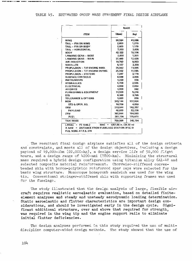
TABLE 45. ESTIMATED GROUP MASS STATEMENT FINAL DESIGN AIRPLANE
ITEM
WING TAIL - FIN ON WING TAIL - FIN ON BODY TAIL - HORIZONTAL BODY LANDING GEAR - NOSE LANDING GEAR - MAIN AIR INDUCTION NACELLES PROPULSION - T/F ENGINE INBD. PROPULSION - T/F ENGINE OUTED. PROPULSION -SYSTEMS SURFACE CONTROLS INSTRUMENTS HYDRAULICS ELECTRICAL AVIONICS FURNISHING & EQUIPMENT ECS TOLERANCE & OPTIONS MEW
OEW STD & OPER. EO.
PAYLOAD 2 FW
FUEL
T MASS -
-
10,700 313.844 49,000
362,844 387,156
(Ibrn)
90,584 2,800 2.600 7,950
42.122 3,000
27,400 19,760 5,137
25,562 25,562 7,007 8,500 1,230 5,700 4,550 1,900
11,500 8,300 1,980
303,144
TAXI MASS
LEMAC = FS 1548.2 MAC = 1351.06 in. (3 750,000
(kg)
41,088 1,270 1,179 3,606
19,106 1,361
12,428 8,963 2,330
11,595 11,595 3,178 3,856
558 2,585 2,064
862 5,216 3,765
898 137,504
4,853 142,357 22.226
164,583 175.61 1
340.194
32 m) X ARM = DISTANCE FROM FUSELAGE STATION (F.S.) 0 FUS. NOSE AT F.S. 279
The r e s u l t a n t f i n a l d e s i g n a i r p l a n e s a t i s f i e s a l l o f t he des ign c r i t e r i a and' constraints, and meets a l l of the des ign ob jec t ives , inc luding a design payload of 49,000-lbm (22,000-kg), a des ign se rv ice l i f e of 50,000 f l i g h t hours , and a design range of 4200-nmi (7800-km). Minimizing t h e s t r u c t u r a l mass requi red a hybrid design configurat ion using t i tanium al loy 6U-4V and selected composite material reinforcement. Chordwise-stiffened convex- beaded skin with boron-polyimide reinforced spar caps were selected for the bas i c wing s t r u c t u r e . Monocoque honeycomb sandwich w a s used for t h e wing t i p . Convent ional s t r inger-s t i f fened skin w i t h supporting frames w a s used fo r t he fu se l age .
The s t u d y i l l u s t r a t e d tha t the des ign ana lys i s o f l a rge , f l ex ib l e air- c r a f t r e q u i r e s r e a l i s t i c a e r o e l a s t i c e v a l u a t i o n , b a s e d on d e t a i l e d f i n i t e - element analyses and steady and unsteady aerodynamic loading determination.
s i d e r a t i o n s , and should be inves t iga ted early in t he des ign cyc le . S ign i - f i can t add i t iona l s t ruc tu re , ove r and above t h a t r e q u i r e d f o r strength, was r e q u i r e d i n t h e wing t i p and the engine suppor t rails t o e l i m i n a t e i n i t i a l f l u t t e r de f i c i enc ie s .
. S t a t i c a e r o e l a s t i c a n d f l u t t e r c h a r a c t e r i s t i c s are important design con-
The des ign ana lyses per formed in th i s s tudy requi red the use of mult i - discipline computer-aided design methods. The s tudy showed t h a t t h e use of

automated modeling techniques and interactive computer graphics can greatly decrease manpower expendi tures and design calendar t i m e .
The d e s i g n a n a l y s e s d e s c r i b e d i n t h e body of t h e r e p o r t , a n d t h e supplementary s tudies conducted in support of these analyses . (e .g . , AppenL: d i ces A , B and C ) , r e s u l t e d i n t h e i d e n t i f i c a t i o n of a number of technology areas w i t h t h e p o t e n t i a l a n d n e e d f o r f u r t h e r d e v e l o p m e n t t o meet t h e an t i c ipa t ed r equ i r emen t s fo r a far-term (1990) d e s i g n a i r c r a f t c o m p e t i t i v e environment. These include advanced composite materials, a i r c r a f t c o n f i g - u r a t i o n improvement, act ive controls , and advanced design analysis methods.
RECOMMENDATIONS
I n a d d i t i o n t o making an i n -dep th s t ruc tu ra l des ign ana lys i s o f t he b a s e l i n e Mach 2.7 arrow-wing s u p e r s o n i c c r u i s e a i r c r a f t , t h e o b j e c t i v e s o f t h e s t u d y i n c l u d e d t h e i d e n t i f i c a t i o n o f o p p o r t u n i t i e s f o r s t r u c t u r a l mass reduction, and the recommendation of needed research and technology.
A ma jo r po ten t i a l sou rce fo r s t ruc tu ra l mass reduct ion i s the i nc reased use of advanced composite materials, p a r t i c u l a r l y when the ca scad ing e f f ec t s on a i r c r a f t s i z e and cost are considered (see Appendix A ) . Continued development of composite materials i s recommended i n s e v e r a l areas. Fur- t h e r development of high-temperature polyimides i s needed i f s i g n i f i c a n t appl ica t ion of composi tes in the Mach 2.7 temperature environment i s t o b e achieved. On the o the r hand , i f lower c ru ise speed des igns , e .g . , Mach 2.2 ( s e e Appendix B ) , are considered, addi t ion-type polyimides are a p o t e n t i a l so lu t ion . F ina l ly , metal mat r ix composi tes o f fe r mass savings for l o c a l " h o t s p o t s , " e . g . , e n g i n e s u p p o r t s t r u c t u r e , a n d f o r s t i f f n e s s c r i t i c a l a r e a s l i k e t h e wing t i p ( s e e Appendix C ) .
Fur ther improvements in a i rc raf t conf igura t ion a re a l so needed . For example, the over -under engine ins ta l la t ion concept needs fur ther explora- t i on . Th i s concep t o f f e r s improved d i r ec t iona l con t ro l by r educ ing two- eng ine f a i l ed r equ i r emen t s , and by i n c r e a s i n g t h e amount of t r a i l i n g edge a v a i l a b l e f o r f l a p e r o n s for increased roll c o n t r o l power. In add i t ion , research and development of high-speed roll cont ro l devices i s needed. Low-speed l i f t improvement i s a l so needed; bo th , powered l i f t and increased wing span o f f e r p o t e n t i a l s o l u t i o n s h e r e .
A s a p a r t o f t h e a i r c r a f t p e r f o r m a n c e i n v e s t i g a t i o n s , t h e u s e of a c t i v e c o n t r o l s w a s p o s t u l a t e d . F u r t h e r s t u d i e s are needed concern ing the i r use f o r p i t c h , r o l l and yaw augmentation, r ide quali ty improvement, increased f a t i g u e l i f e , f l u t t e r s u p p r e s s i o n a n d o t h e r a e r o e l a s t i c a p p l i c a t i o n s .
A number of needed improvements i n advanced design analysis methods were ident i f ied dur ing the s tudy . These inc luded t ransonic loads p red ic- t i o n methods , b e t t e r f l u t t e r o p t i m i z a t i o n t e c h n i q u e s , a n d improved computer- a ided des ign capab i l i t i e s . I nc luded i n t he l a t t e r were au tomated da t a gene ra t ion , i n t eg ra t ion o f t he des ign ana lys i s sys t em and t h e a s s o c i a t e d d a t a management sys tem, and in te rac t ive des ign ana lys i s . F ina l ly , there i s a need fo r cos t p red ic t ion methods fo r compos i t e s t ruc tu res .


APPENDIX A
ADVANCED TECHNOLOGY ASSESSMENT
In t roduc t ion
P rev ious s tud ie s o f advanced t echno logy app l i ca t ion t o future t r a n s - port performance and economics ident i f ied major technological advances tha t cou ld r easonab ly be ava i lab le dur ing the 1990- t ime per iod (Refer- ence 1 2 ) . The t r e n d s i n d i c a t e d t h a t t h e g r e a t e s t s t r u c t u r a l mass payoff w a s i n t he . a rea o f compos i t e materials and fabr icat ion technology. Furthermore, t h e most s i g n i f i c a n t mass r e d u c t i o n r e s u l t e d f r o m r e s i z i n g t h e a i r p l a n e t o . r e f l e c t t h e l o w e r s t r u c t u r a l mass achieved through advanced materials app l i ca t ion .
The impact of advanced technologies on s u p e r s o n i c c r u i s e a i r c r a f t d e s i g n were i d e n t i f i e d i n t h e e a r l y t a s k s o f t h e s y s t e m s i n t e g r a t i o n s t u d i e s (Ref- e rence 4 ) . Technology improvements i n composite materials, new s t r u c t u r a l concep t s , and ac t ive con t ro l s were c o l l e c t i v e l y f o r e c a s t e d . P r o j e c t e d com- pos i te deve lopment t rends pos tu la ted the ava i lab i l i ty o f improved s tab le high temperature res in systems such as thermoplast ic polyimides or high tempera ture po lyaromat ics ; l a rge numer ica l ly cont ro l led t ape l ay ing equip- ment , f i lament winding and pul t rusion equipment; and larger autoclaves. The s tud ie s i nd ica t ed t ha t , w i th t he aggres s ive app l i ca t ion o f compos i t e materials and f ab r i ca t ion t echno logy , t he t akeof f g ros s mass o f t h e n e a r - t e r m a i r c r a f t d e s i g n r e p o r t e d i n t h e body of this report could be reduced by approximately 100,000-lbm (45,400-kg), o r t he r ange i nc reased by 500-nmi (926-km).
Approach
To a r r i v e a t p r o j e c t i o n s for airframe s t r u c t u r a l mass f o r t h e a s s e s s - ment of t h e impact of advanced composite materials technology on the s u p e r s o n i c c r u i s e a i r c r a f t d e s i g n , t h e r e s u l t s o f the design concept eva lua t ion for t he r e f e rence conf igu ra t ion were used t o s i z e s p e c i f i c p o i n t des ign reg ions . The s i z i n g d a t a i n c l u d e d t h e i n t e r n a l l o a d s a n d s t i f f n e s s requirements of the ' appropriate a i r f rame arrangements ( i .e . , chordwise- s t i f f e n e d and monocoque d e s i g n s ) . A comparison w a s t h e n made w i t h t h e minimum mass t i t a n i u m d e s i g n t o similar d e s i g n s i n g r a p h i t e or boron com- pos i t e s . Reduc t ion f ac to r s fo r s econda ry and o t h e r s t r u c t u r a l components were obtained from the results of Reference 1 2 . The b a s i c s e c t i o n mass w a s taken as t h e basis of comparison since nonoptimum f a c t o r s r e s u l t i n g from advanced manufac tur ing techniques used for the near - te rm a i rc raf t assembly (e .g . , welded des ign) were o f f s e t by a bonded composite structure having a p p r o x i m a t e l y e q u a l u t i l i z a t i o n of mechanical fas teners .
Considering the 1990-time period, adjustments were made i n t h e material p r o p e r t i e s t o r e y l e c t improvements an t ic ipa ted for these materials. I n making t h e a d j u s t m e n t s , no major breakthroughs have been forcasted. Rather, it w a s p o s t u l a t e a t h a t as a minimum, c u r r e n t i n c o n s i s t e n c i e s i n t h e m a t e r i a l p r o p e r t i e s would diminish through ref ined processing.
107
It w a s recognized tha t composi te materials r e q u i r e p r o v i s i o n s for pro tec t ion beyond t ha t of t h e i r all-metal c o u n t e r p a r t s . I n p a r t i c u l a r it w a s necessary to p ro tec t aga ins t degrada t ion by aggress ive envi ronments such as e l ec t r i ca l haza rds , e ros ion , impac t , and wea the r ing . For t h i s s tudy a l l e x t e r i o r s u r f a c e s were assumed t o be covered wi th 200 x 200 alum- inum mesh, except a t the l ead ing edge s ec t ions where 120 x 120 mesh w a s used. The 120 x 120 mesh w a s s e l e c t e d f o r the l ead ing edge to improve hea t d i s s i p a t i o n f o r t h i s area. Addi t iona l composi te p ro tec t ion was provided by an e l e c t r i c a l i n s u l a t i n g barrier c o n s i s t i n g o f one p l y o f 120 g l a s s laminated between the 1aminAte and the aluminum w i r e mesh. The 120 glass barr ier p ly and t he aluminum wire mesh were c o c u r e d w i t h t h e r e s i n f r o m t h e 120 g lass , bonding the mesh t o t h e c o m p o s i t e . The wire mesh w a s connected t o m e t a l l i c s u b s t r u c t u r e t o p r o v i d e a p a t h f o r e l e c t r i c a l d i s c h a r g e . O t h e r p r o t e c t i v e measures inc lude coa t ing a l l su r faces w i th a polyurethane system (more des i rab le , h igher se rv ice t empera ture sys tems are an t i c ipa t ed by 1985), s e a l i n g a l l cut edges, and w e t i n s t a l l a t i o n o f f a s t e n e r s .
Design Concepts
The composi te design concepts that were examined were var ia t ions of t h o s e e v a l u a t e d f o r t h e m e t a l d e s i g n , and i n c l u d e d b o t h b i a x i a l l y and u n i a x i a l l y s t i f f e n e d s u r f a c e p a n e l s . All t h e wing surface panel concepts (F igure 61) were smooth-skin designs which exploi ted the low coeff ic ient of thermal expans ion charac te r i s t ics inherent in the g raphi te -poly imide system. For the f u s e l a g e , t h e more conventional skin-stringer and frame designs were evaluated.
Manufacturing Concept
The p r i n c i p a l p r e m i s e f o r p r o d u c i n g t h e 1990 advanced technology a i r c r a f t w a s t ha t polyimide res in systems would have been developed to a poin t such tha t p rocess ing could be accompl ished wi th ease . Thus, t h e low cost manufacturing methods now being developed for epoxy processing were taken as f eas ib l e fo r po ly imides . Res t r i c t ions on such factors as laminated th i ckness , bond p r e s s u r e , e t c . , w e r e n e g l e c t e d f o r t h i s s tudy .
Fabr i ca t ion of r ib s and spa r caps as w e l l as t r u s s webs w a s accom- p l i shed by c losed mold process ing wi th e las tomer ic too l ing as a p res su re generator. Single-stage molding and attachment of caps t o truss or corru- ga t ed webs were performed by similar techniques .
Wing sk in pane l s , honeycomb o r ha t - s t i f f ened , would be produced with l a rge shee t s o f mat,erial laminated by automated machines. Unit panels
S i n c e , f o r t h e most p a r t , t h e wing skin gages were small, t h e h a t - s t i f f e n e r s were f i r s t produced as t r apezo ida l co r ruga t ions molded from a f la t shee t . The h a t s were then cocured to the sk ins us ing removable expans ion mandre ls . Because of contour complexi ty , f lexible e las tomeric tool ing w a s used ex tens ive ly .
, having dimensions of 10-feet x 20-feet (3.0-m x 6.1-m) were assumed.
108
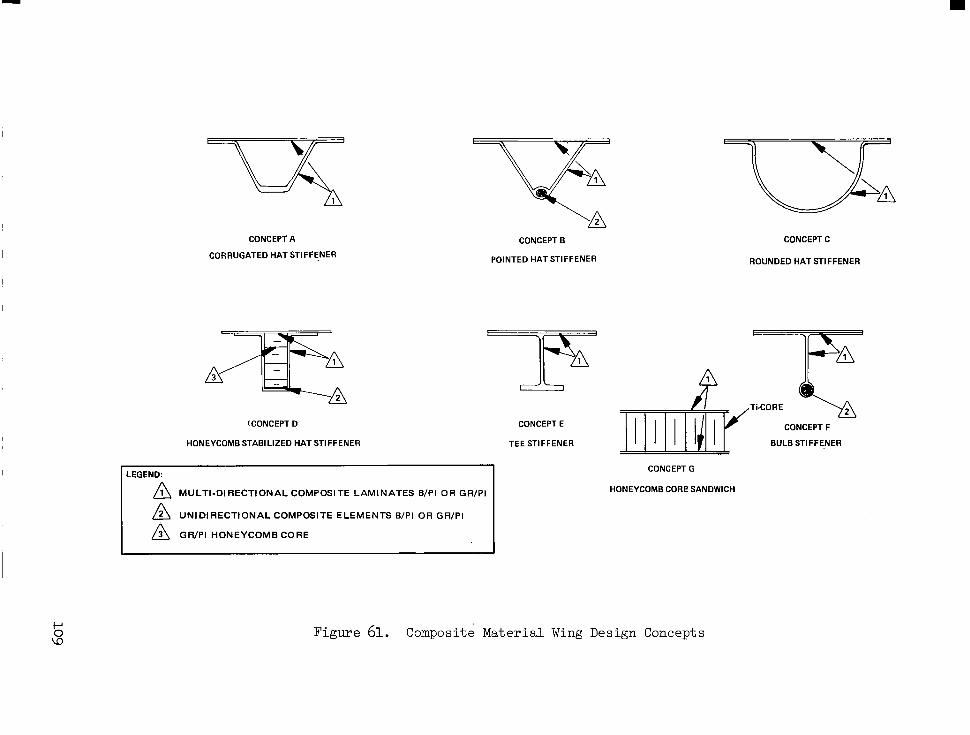
CONCEPT A
CORRUGATED HAT STIFFENER
A
CONCEPT B
POINTED HAT STIFFENER
(CONCEPT D
HONEYCOMB STABILIZED HAT STIFFENER
LEGEND:
M U L T I - D I R E C T I O N A L C O M P O S I T E L A M I N A T E S B/PI OR GR/P I
A U N I D I R E C T I O N A L C O M P O S l T E E L E M E N T S B/PI OR GR/P I
A G R / P I H O N E Y C O M B C O R E
CONCEPT E
TEE STIFFENER
CONCEPT C
ROUNDED HAT STIFFENER
CONCEPT F
BULB STIFFENER
CONCEPT G
HONEYCOMB CORP SANDWICH
Figure 61. Composite Mater ia l Wing Design Concepts

Point Design Regions
Selected point design regions used in the metallic concept, evaluations were used to establish unit mass data for estimating the total airplane mass of the composite designs. Representative structures were defined and analyzed at these locations, including consideration of the associated non-optimum factors. In the wing, these included upper and lower surface panels, and typical rib and spar structure.
Design Loads
The internal loads and surface pressures for the critical load condi- tions from the metallic concept evaluation were used in the analyses of the composite designs; load reduction based on the reduced airframe mass poten- tial of composites application was not included. In addition, the stiff- ness of the composite shell structure was maintained at least equivalent to the titanium shell design.
Concept Analyses
Wing concept analyses were performed for both the chordwise-stiffened and the monocoque arrangements. Screening of the potential all-composite design concepts of Figure 61 were performed both on a qualitative and quantitative basis. The results of this assessment identified the corrugated hat-stiffener (Concept A) and the tee-stiffener (Concept E) as the leading candidates for the all-composite design. The former provides good compres- sion efficiency and excellent torsional rigidity. For the more lightly loaded, pressure critical forward wing box structure, the tee-stiffener concept was also evaluated.
For the monocoque design only the honeycomb sandwich panel with lami- nated face skins of boron-polyimide or graphite-polyimide composites and a titanium alloy core was evaluated.
Table 46 presents a comparison of unit wing mass for the three point design regions for the chordwise-stiffened hat section design, and the monocoque honeycomb sandwich design. The unit mass data for the surface panels and individual substructure components are shown. The minimum mass design for each point design region is identified by the shading. Trends similar to the metallic design are noted, with the.chordwise-stiffened design being minimum-mass for the lightly loaded forward box region (40322) and the honeycomb design being minimum-mass for the highly loaded aft box and the stiffness critical wing tip structure. These unit mass data were applied to establish the total wing mass for the advanced technology aircraft.
The assessment to identify the potential payoff for composite tech- nology application to the fuselage shell structure was made observing prac- tical constraints for passenger accommodation. The two major factors included: (1) the need for passenger windows and (2) the requirement for ingress and emergency egress. To obtain the design trends for this study,
110

POINT DESIGN REGION
STR. ARRANGEMENT
COMPOSITE MATERIAL
PANEL CONCEPT
UPPER SURFACE
LOWER SURFACE
TRUSS SPAR
CORRUGA. SPAR
TRUSS RIB
CORRUGA. RIB
SPAR CAP
RIB CAP
ZTOTAL
TABLE 46. WING MASS COMPARISON FOR COMPOSITE DESIGNS
40322 I
1.037 (5.06)
0.950 (4.63)
0.267 (1.30)
0.763 (3.72)
0.362 (1.77)
0.422 (2.06)
0.177 (0.86)
0.137 (0.67)
4.115 (20.09)
-
NOTE: SPAR SPACING = 30 in (0.76 rn)
UNITMASS: X.XXX = Ibm/ft2; (X.XXX) = k g h 2
40E
CHORDWISE
GrT-GT n -
1.694 (8.27)
1.41 2 (6.89)
0.656 (3.20)
0.716 (3.49)
0.P9S (0.48)
0.798 (3.90)
3.795 (18.53)
0.1 18 (0.58)
9.288 (45.35)
-
- 1.674
(8.17)
1.394 (6.80)
0.663 (3.24)
0.71 1 (3.47)
0.100 (0.49)
0.792 (3.87)
3.761 (18.36)
0.117 (0.57)
9.212 (44.98)
-
i i 41:
- 1.443
(7.04)
0.993 (4.85) -
0.541 (2.64) -
0.399 (1.95)
3.552 117.34)
0.117 (0.57)
7.045 134.40)
- -
P P
r

constraints on frame spacing of 20-in (0.51-m) and frame height of 3.0-in (7.6-cm) were observed. Furthermore, the aforementioned constraints were c o n s i s t e n t w i t h t h e titanium skin-s t r inger and frame des ign and thus a direct comparison can be made t o re la te more d i r e e t l y t h e i m p a c t o f com- p o s i t e u t i l i z a t i o n on the p r imary she l l s t ruc tu re des ign .
The fuse l age of t h e s u p e r s o n i c c r u i s e a i r c r a f t w a s b e n d i n g c r i t i c a l over most of i t s l eng th , w i th i n t e rna l p re s su re d i c t a t ing r equ i r emen t s f o r the shel l s t ructure design forward of FS 1000. The tee-stiffener design was adopted for the l ight ly loaded, pressure cr i t ical forebody s t ructure . For t h e bending cr i t i ca l reg ions bo th the t ee-s t i f fener and corrugated hat- s t i f fener designs were evaluated.
The results of the fuse lage sk in pane l and frame a n a l y s i s are summar- i z e d i n Table 47. The r e s u l t i n g mass t rends for both boron-polyimide and graphite-polyimide composites are d isp layed for the pane l concepts ana lyzed . S imi l a r t r ends as o b s e r v e d f o r t h e m e t a l l i c d e s i g n are i n d i c a t e d , w i t h t h e tee-stiffener being minimum-mass i n t h e forebody and the hat-s t r inger design being minimum-mass i n the centerbody and af tbody s t ructure . da ta inc lude an estimate f o r t h e p r o t e c t i o n s y s t e m mass of 0.045-lbm/ft ( .22-kg/m2). Also shown o n t h e t a b l e i s a summary of frame mass f o r t h e poin t des ign reg ions . The frame mass a t FS 750 was conserva t ive ly t aken as being equal t o t h e requirements a t FS 2000 and FS 3000.
The2
Mass Assessment
The r e l a t i v e mass of t h e wing box s t r u c t u r e w a s based on th ree wing poin t des ign reg ions . The t o t a l variable box mass i s p r e s e n t e d i n T a b l e 48 for the ind iv idua l boxes ( i . e . , forward, a f t , t i p ) . These r e s u l t s are compared w i t h t h e near-term hybr id a r rangement (Table 25) o f the de ta i l concept evaluat ion s tudy.
Evaluation of the wing box mass da ta fo r t he nea r - t e rm and far-term d e s i g n s i n d i c a t e t h e mass advantage of the minimum gage t i t an ium a l loy beaded panels of the foward box as compared t o an equ iva len t s t i f fnes s composite design of ei ther boron-polyimide or graphite-polyimide. For t h e s t i f f n e s s c r i t i c a l t i p s t r u c t u r e , however, the application of composites a f f o r d s a s i g n i f i c a n t mass saving.
The re la t ive mass of t h e s h e l l s t r u c t u r e was based on t h e f o u r p o i n t des ign reg ions def ined a t FS 750, FS 2000, FS 2500 and FS 3000. Table 49 p r e s e n t s t h e s h e l l u n i t mass fo r each po in t des ign r eg ion and r e su l t i ng t o t a l s h e l l mass. Both boron-polyimide and graphite-polyimide material sys tem da ta a re shown along with corresponding mass f o r t h e a l l - t i t a n i u m s h e l l . A d e c r e a s e i n s h e l l u n i t mass w a s r e f l e c t e d a t a l l po in t des ign regions; the magni tude var ies f rom a 4-percent t o a 21-percent mass saving p o t e n t i a l . A mass s a v i n g s f o r t h e t o t a l s h e l l when employing advanced composites w a s 14-percent.
The mass reduc t ion f ac to r s fo r t he s econda ry components were obta ined from Reference 12. The secondary components for t h e wing and f u s e l a g e t o t a l i n e x c e s s of 60,000-1bm (27,000-kg). The app l i ca t ion o f t he r educ t ion
112
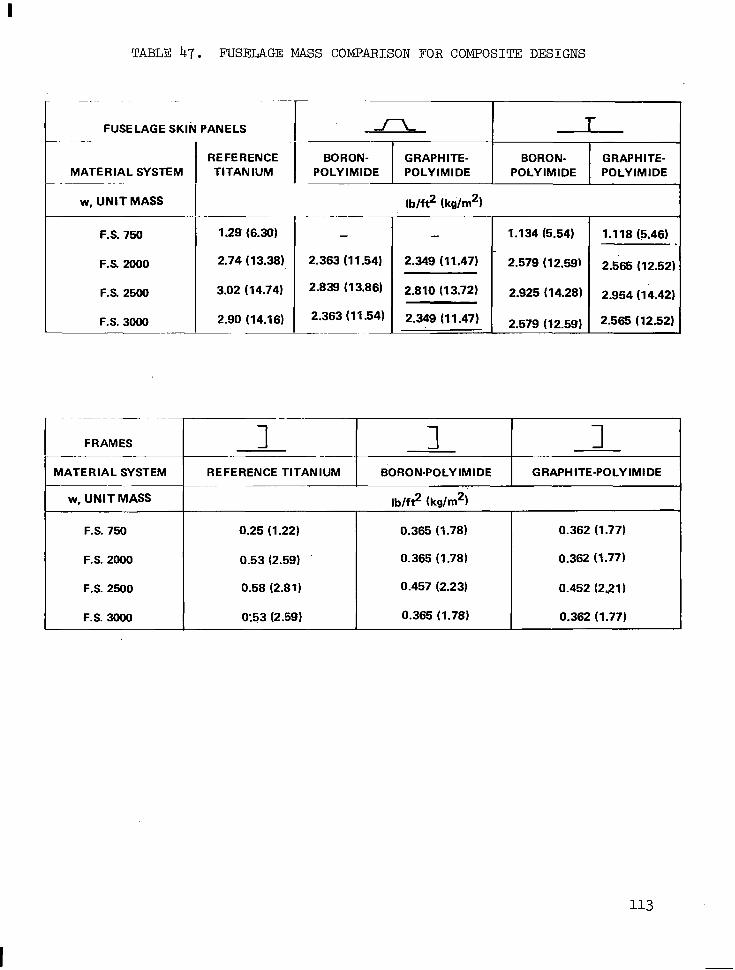
TABLE 47. FUSELAGE MASS COMPARISON FOR COMPOSITE DESIGNS
FUSELAGE SKIN PANELS
MATERIAL SYSTEM . ~ ~ -
w, UNIT MASS
F.S. 750
F.S. 2000
F.S. 2500
F.S. 3000
REFERENCE TITANIUM
1.29 (6.30)
2.74 (13.38)
3.02 (14.74)
2.90 (14.16)
I
BORON- GRAPHITE- BORON- GRAPHITE-
-
2.363 (1 1.54)
2.839 (1 3.86)
lb/f? (ke/rn2) ~~
- 2.349 (11.47)
2.810 (13.72)
2.349 (1 1.47) I 1.1 34 (5.54)
2.579 (12.591
2.925 ( 14.28)
2.579 (12.59)
1.118 (5.46)
2.565 (12.52)
2.954 (14.42)
2.565 (12.52)
FRAMES 1 1 1 I
MATERIAL SYSTEM 1 REFERENCE TITANIUM I BORON-POLYIMIDE I GRAPHITE-POLYIMIDE 1 w, UNIT MASS I
~~
F.S. 750
0.452 (231 1 0.457 (2.23) 0.58 (2.81) F.S. 2500
0.362 (1.77) 0.365 (1.78) 0.53 (2.59) F.S. 2000
0.362 (1.77) 0.365 (1.78) 0.25 (1.22)
F.S. 3000 0.362 (1.771 0.365 (1.781 0:53 (2.59)

TABLE 48. WING BOX STRUCTURE MASS COMPARISON
NEAR-TERM TECHNOLOGY ADVANCED TECHNOLOGY
ITEM HYBRID@) B/P I Gr/PI
STARTSFDESIGN iLEGGzr FAR-TERM (1990)
WING BOX FORWARD Ibm (kg) 20 j580(B) AFT Ibrn (kg) 17 384 TIP Ibrn (kg) 6 964
FLUTTER INCR Ibm (kg) 2 340(c) ZTOTAL Ibm (kg) 47 268
(19.48) (35.30) (23.09)
~
(9,802) (7,842) (2,716) (376)
;20 736) "
3.96 7.15 4.7 1
21,446 17,097 5 963
773(c: 45 279
UOTES: (A) COMPOSITE REINFORCED SPAR CAPS; BEADED PANELS EXCEPT H/C SANDWICH TIP BOX.
(6) SIGNIFICANT ADVANTAGE OF METAL SURFACE PANELS AND COMPOSITE REINFORCED SPAR CAPS.
(C) SIGNIFICANT ADVANTAGE OF COMPOSITE SANDWICH APPLICATION TO THE TIP STRUCTURE; FLUTTER INCREMENT BASED ON G/p RELATIONSHIP ASSUMING k450 LAYUP.
TABLE 49. FUSELAGE SHELL STRUCTURE MASS COMPARISION
I MATERIAL SYSTEM: NEAR-TERM FAR TERM PERCENT
TITANIUM BORON
F.S. 750
F.S. 3oOO Ibm/ft2 (kg/m2k 3.43 (16.74) 2.73 (13.33)
WSHELL Ibm (kg) 23,148 (low) 20,178 (9152)
GRAPHITE POLYIMIDE
CHANGE OVER
NEAR-TERM
-3.9 -17.1
-7.6 -21.0
-13.7
1
f a c t o r s t o t h e d e s i g n r e s u l t s i n a p o t e n t i a l s t r u c t u r a l mass savings of approximately 10,000-lbm (4540-kg). These items a lone o f f e r s ign i f i can t mass payoff. and improve a i r c r a f t performance fo r t he supe r son ic c ru i se air- c ra f t des ign .
A comparison of t o t a l mass t r e n d s f o r t h e f a r - t e r m advanced technology supe r son ic c ru i se a i r c ra f t and t h e near-term a i r c r a f t i s p r e s e n t e d i n Table 50. A s i g n i f i c a n t improvement i n t h e f u e l f r a c t i o n f o r t h e f i x e d - s i z e and -takeoff mass a i rp l ane i s shown for the a l l -composi te design. The range is increased from 4183-nmi (7747"k.m) t o an excess of 4600-nmi (8519-km), while holding the payload constant a t 49,000-lbm (22,000-kg).
Another approach t o e x p l o i t t h e mass advantages of composite applica- t i o n t o t h e f a r - t e r m d e s i g n w a s t o r e s i z e t h e a i r p l a n e s t o m a i n t a i n a range of 4200-mi (7778-km) with a payload of 49,000-lbm (22,000-kg). The wing loading , t akeoff th rus t - to-mass ra t io and fue l f rac t ion were e s s e n t i a l l y he ld cons tan t . For th i s case , the t akeoff mass i s 641,500-lbm (291,000-kg) f o r t h e composite hybrid design. The wing a rea was reduced t o approximately 9300-ft2 ( 864-m2). A s i n d i c a t e d i n t h e t a b l e , t h e z e r o f u e l mass w a s reduced t o 306,046-lbm (138,800-kg) fo r t he r e s i zed hybr id a i r ca r f t . Th i s reduct ion of approximately 15-percent would r e s u l t i n a commensurate reduc- ' t i o n i n flyaway cost.
Advanced Technology Airplane
The f i n a l des ign r e su l t i ng from t h i s advanced technology assessment w a s a hybrid s t ructural approach shown in F igure 62. The design makes ex tens ive use of graphite-polyimide material system with a protect ive system of aluminum wi re f ab r i c and 120 g l a s s . The chordwise-s t i f fened s t ruc tura l arrangement with the convex-beaded surface panel concept of t i tanium al loy Ti-6A1-4V r e s u l t e d i n m i n i m u m mass for the l igh t ly loaded forward wing box s t ruc tu re . Fo r t he s t r eng th c r i t i ca l w ing-a f t box and s t i f fness des igned wing- t ip s t ruc ture , the honeycomb-core sandwich using graphite-polyimide f ace sk in was found t o be.minimum-mass. The fuselage s t ructural arrange- ment i s a skin-stringer-frame approach employing closed trapezoidal hat s t i f f e n e r s i n t h e , c e n t e r b o d y and aftbody, with tee-stiffeners used i n t h e pressure c r i t i ca l forebody des ign .
The r e s u l t s of t h i s assessment have ident i f ied the potent ia l benefi ts o f the composite materials and f ab r i ca t ion t echno logy fo r app l i ca t ion t o a 1990-plus start-of-design Mach 2.7 supersonic c ru ise t ranspor t . The impact on t h e a i r p l a n e s i z e and mass are s ign i f icant bu t requi re fur ther in -depth a n a l y t i c a l and exper imenta l s tud ies for va l ida t ion , inc luding damage to le rance ana lys i s .
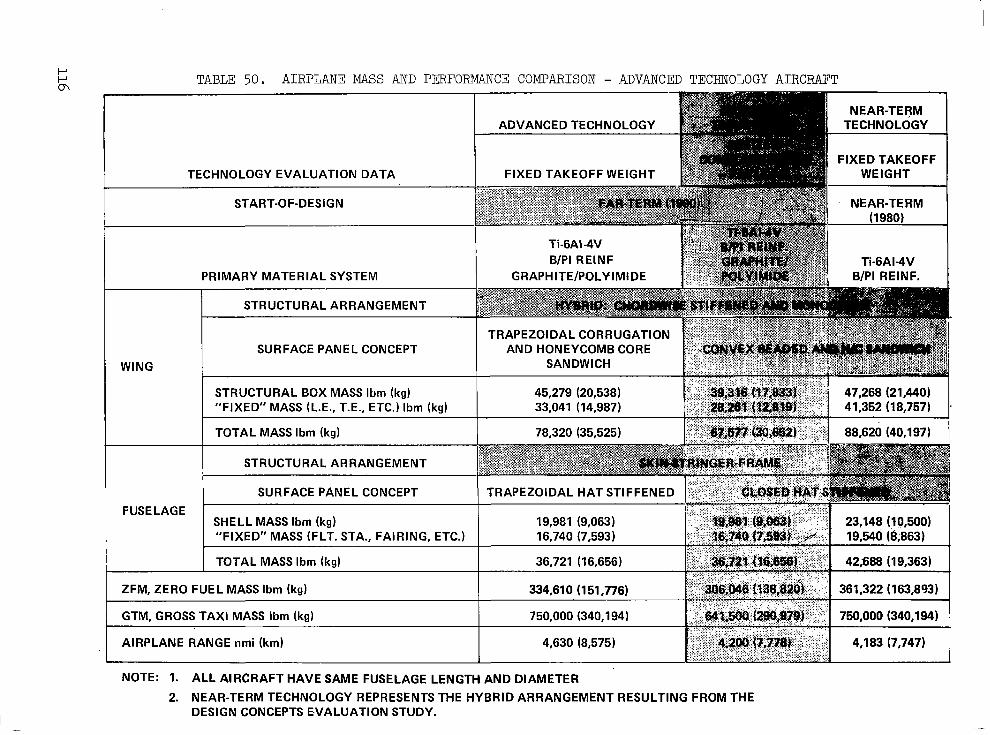
TABLE 50. AIRPLANE MASS AND PERFORMANCE COMPARISON - ADVANCED TECHNOLOGY AIRCFAFT
I TECHNOLOGY EVALUATION DATA I FIXED TAKEOFF WEIGHT I ~ FIXED TAKEOFF
WEIGHT
SURFACE PANEL CONCEPT I AND HONEYCOMB CORE 1 WING SANDWICH
FUSELAGE t
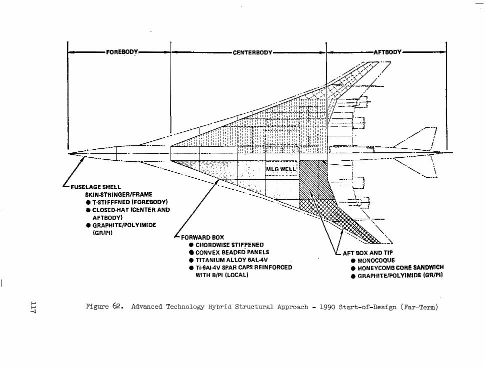
c - FOREBODY- c CENTERBODY - I - AFTBODY m
FUSELAGE SHELL SKIN-STRINGEWFRAME 0 T-STIFFENED (FOREBODY) a CLOSED-HAT (CENTER AND.
AFTBODY) 0 GRAPHITE/POLYIMIDE
(GRIPI)
0 CHORDWISE STIFFENED CONVEX BEADED PANELS AFT BOX AND TIP
0 TITANIUM ALLOY 6AL-4V 0 MONOCOQUE 0 Ti-6AI-4V SPAR CAPS REINFORCED 0 HONEYCOMB CORE SANDWICH
WITH B/PI (LOCAL) 0 GRAPHITE/POLYIMIDE (GR/PI)
Figure 62. Advanced Technology Hybrid Structural Approach - 1990 Start-of-Design (Far-Term)

APPENDIX B
MACH 2.2 CRUISE SPEED ASSESSMENT
In t roduct ion
Cruise speed select ion i s a fundamental design consideration for a supe r son ic c ru i se a i r c ra f t . To provide addi t ional guidance to i t s s e l e c t i o n f o r f u t u r e s u p e r s o n i c c r u i s e a i r c r a f t d e s i g n s , an assess- ment w a s made t o e s t a 5 l i s h t h e changes t o t h e f i n a l d e s i g n a i r p l a n e d i c - t a t e d by tempera tures assoc ia ted wi th a c r u i s e Mach number of Mach 2.2. F i n a l c r u i s e s p e e d s e l e c t i o n i s an involved process requir ing an assess- ment of no t on ly a i rp lane per formance , bu t a l so the t echnology advances requi red to ach ieve th i s per formance , and the deve lopment cos ts and r i s k a s soc ia t ed w i th t hese advances i n t he s t a t e -o f - the -a r t . Th i s s tudy p ro - v ided fu r the r i n s igh t i n to t he des ign concep t and ma te r i a l t r ends r e l a t ed to the reduced thermal envi ronment a t Mach 2.2, and mass e s t ima tes for modifying previous f indings.
The performance a t ta inable by ope ra t ing t he Mach 2 . 7 d e s i g n a i r c r a f t a t an o f f -des ign c ru ise Mach number of 2 .2 without any physical modif ica- t i o n t o t h e a i r p l a n e was determined. The r e su l t i ng changes i n ope ra t ing d r a g l e v e l s and engine per formance d ic ta ted the fo l lowing des ign f l igh t p r o f i l e :
Dispatch mass Block f u e l Landing mass Reserve fuel Zero fue l mass Mission range Mission t ime Time-at-cruise C r u i s e a l t i t u d e
750,000-lbm (340,000-kg) 320,600-lbm (145,400-kg) 423,600-lbm (19hy800-kg)
64,300-lbm (29,200-kg) 365,300-lbm (165,700-kg)
3 , 6 40-mi ( 6,730-km) 3.5-hrs 2.6-hrs
59,750-ft (18,200-111)
Structural Temperatures
Reducing the cruise speed from Mach 2.7 (Mach 2.62 Hot Day) t o Mach 2.2 (Mach 2.16 Hot Day) p r o v i d e d t h e t e m p e r a t u r e r e l i e f i n d i c a t e d i n F igure 63. The ex te rna l su r f ace i so the rms fo r t he a i rp l ane l ower su r f ace at both Mach 2.62 and Mach 2.16 Hot Day cru ise conct i t ions a re shown.
Wing and fuselage s t ructure temperatums were determined f o r s e l e c t e d poin t des ign reg ions a t t h e f o l l o w i n g f l i g h t s c o n d i t i o n s : Mach 0.90 climb, Mach 1.25 climb, Mach 2 .2 s ta r t -of -c ru ise , Mach 2.2 mid-cruise, and Mach 1.25 descent . The s t ruc tu ra l t empera tu res were u sed t o de t e rmine t he e f f e c t o f a reduced thermal environment on the f inal design a i rplane s t ruc tu ra l a r r angemen t , des ign concep t s , materials a n d a i r c r a f t mass.
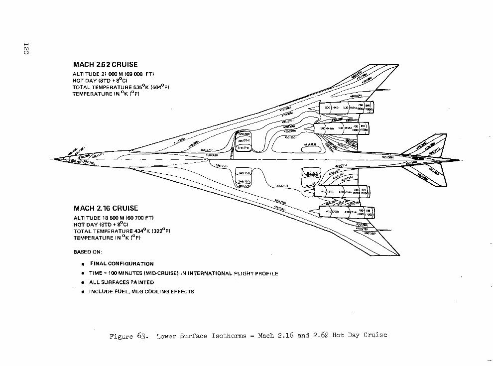
MACH 2.62 CRUISE ALTITUDE 21 OOO M (69 OOO FT) HOT DAY (STD + 8OC) TOTAL TEMPERATURE 535OK (504OFJ TEMPERATURE IN OK (OF)
MACH 2.16 CRUISE ALTITUDE 18 500 M (60 700 FT) HOT DAY (STD + 8OC) TOTAL TEMPERATURE 434'K (322OF) TEMPERATURE IN OK (OF)
BASED ON:
0 FINAL CONFIGURATION
0 TIME = 100 MINUTES (MID-CRUISE) IN INTERNATIONAL FLIGHT PROFILE
0 ALL SURFACES PAINTED
0 INCLUDE FUEL, MLG COOLING EFFECTS
Figure 63. Lower Surface Isotherms - Mach 2.16 and 2.62 Hot Day Cruise

Airframe Mass Trends
The reduced temperatures a t Mach 2.2 would permit the use of aluminum material . For this assessment, the use of material properties for aluminum a l loy 2024-T81 w a s spec i f ied ; the p roper t ies o f th i s a l loy are similar t o aluminum al loy 2618, which i s an equivalent t o t h e B r i t i s h a l l o y R R 5 8 used on t h e Anglo-French Concorde.
Analyses were made of the impact of the reduced cruise speed on t h e estimated mass of .the f ina l des ign a i rp lane . The r e s u l t s of t h e mass analyses are summarized i n Figure 64. The basel ine Mach 2.7 airframe w a s 85-percent titanium, 5-percent aluminum, 4-percent composites, and 6-percent other mater ia ls , including s teel . A t a cruise speed of Mach 2.2 a s i g n i f i - cant amount of aluminum could be used, par t icular ly in the wing and t a i l s t ruc ture . . However, as ind ica ted in the f igure , the increased use o f aluminum r e s u l t s i n an inc rease i n s t ruc tu ra l mass.
Assuming tha t bo th t he Mach 2.7 and Mach 2.2 a i r c r a f t would have t h e same productivity on scheduled trans-Atlantic service, then the Mach 2.2 airplane would real ize higher values of u t i l i z a t i o n . To permit a fa i r comparison between these two a i rp lane des igns , the h igher u t i l i za t ion airplane must be designed t o have added fa t igue- l i fe so as t o r e f l e c t a longer airframe-ltfe. Spec i f ica l ly , s ince the Mach 2.7 desi-gn was de- s igned for 50,000 hours , the h igher u t i l i za t ion Mach 2.2 airplane must be made good f o r 58,000 hours. Approximately 24 percent of the baseline airframe mass was dependent upon fatigue allowables, and as a r e s u l t t h e airframe mass inc reases s l i gh t ly when designing to higher values of s e r v i c e l i f e .
1-40 r ALUMINUM 4.6% TITANIUM 85.446 COMPOSITES 3.7% STEEL 1.9% OTHERS 4.4% 1.30
r
a f LL
5 w 1.10 >
5 a YI
1 .oo INCREASING ALUMINUM USAGE
MACH 2.7 i I 1 I I I I I I I I 0 20 40 60 80 100
PE.RCENT TITANIUM
Figure 64. Airframe Mass Trends
121
Conclusions
me impact of using a larger percentage of aluminum and designing - t h e airframe f o r a longer fa t igue l i f e w a s an increase in opera t ing empty mass and takeoff gross mass. The i n c r e a s e i n a i r p l a n e d e s i g n g r o s s mass was 25,000-lbm (11,000-kg) for constant payload-range. The assoc ia ted impact on a i rp lane ' s ize and cos t d ic ta tes ex tens ive use of t i tanium, and of composi te re inforcement of the t i tanium substrate . The c o s t e f f e c t i v e reg ions for appl ica t ion of aluminum a re i n t he s econda ry components such as t h e l i f t i n g s u r f a c e l e a d i n g a n d t r a i l i n g e d g e s t r u c t u r e s . The results of the s tudy i nd ica t ed t ha t t he amount of aluminum used could be increased t o 25-percentY and the amount of titanium reduced t o 68-percent. With t h i s l imi ted use o f aluminum, t h e r e i s a c t u a l l y a s l igh t dec rease i n f l yaway and opera t ing cos ts (2-percent ) . This i s because of the lower material and f a b r i c a t i o n c o s t s f o r aluminum. However, t h i s i s an i n s i g n i f i c a n t e f f e c t i n r e l a t i v e c o s t , and i n d i c a t e s t h a t t h e r e i s l i t t l e to be ga ined by reducing t h e c r u i s e s p e e d t o Mach 2.2.
1 2 2
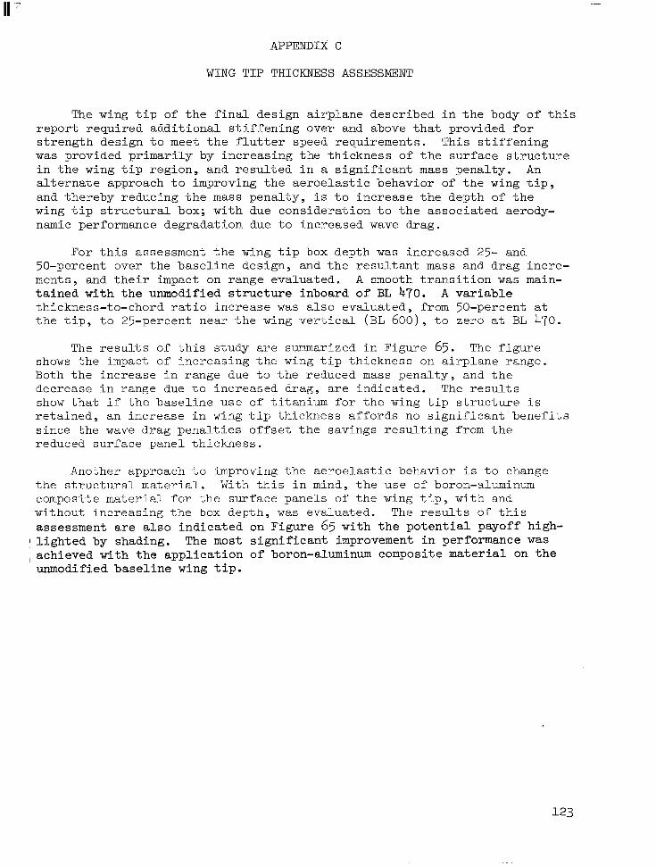
APPENDIX C
WING TIP THICKNESS ASSESSMENT
The wing t i p o f t h e f i n a l d e s i g n a i r p l a n e d e s c r i b e d i a t h e body o f t h i s r e p o r t r e q u i r e d a d d i t i o n a l s t i f f e n i n g o v e r and above t h a t p r o v i d e d f o r s t r e n g t h d e s i g n t o meet t h e f l u t t e r s p e e d r e q u i r e m e n t s . T h i s s t i f f e n i n g w a s p rovided pr imar i ly by i n c r e a s i n g t h e t h i c k n e s s o f t h e s u r f a c e s t r u c t u r e i n t h e wing t i p r e g i o n , a n d r e s u l t e d i n a s i g n i f i c a n t mass penal ty . An a l t e rna te app roach t o improv ing t he ae roe la s t i c behav io r of t h e wing t i p , and thereby reducing the mass pena l ty , i s t o i n c r e a s e t h e d e p t h o f t h e wing t i p s t r u c t u r a l box; with due consideration t o t h e a s s o c i a t e d aerody- namic performance degradation due to increased wave drag.
F o r t h i s a s s e s s m e n t t h e wing t i p box depth w a s increased 25- and 50-percent over the base l ine des ign , and the resu l tan t mass and drag incre- ments , and their impact on range evaluated. A smooth t r a n s i t i o n w a s main- t a ined w i th t he unmodi f i ed s t ruc tu re i nboa rd o f BL 470. A variable th i ckness - to -chord r a t io i nc rease w a s a l so eva lua ted , from 50-percent a t t h e t i p , t o 2 5 - p e r c e n t n e a r t h e wing v e r t i c a l (BL ~oo), t o z e r o a t BL 470.
The r e s u l t s of t h i s s t u d y a r e summarized i n F i g u r e 65. The f i g u r e shows t h e impact o f increas ing the wing t ip th ickness on a i rp lane range . Both t h e i n c r e a s e i n r a n g e due t o t h e r e d u c e d mass pena l ty , and t he dec rease i n r ange due t o i n c r e a s e d d r a g , are ind ica t ed . The r e s u l t s show t h a t i f t h e b a s e l i n e u s e o f t i t a n i u m f o r t h e wing t i p s t r u c t u r e i s r e t a i n e d , a n i n c r e a s e i n wing t i p t h i c k n e s s a f f o r d s no s i g n i f i c a n t b e n e f i t s s i n c e t h e wave d r a g p e n a l t i e s o f f s e t t h e s a v i n g s r e s u l t i n g from t h e reduced sur face pane l th ickness .
Another approach t o improving the aeroe las t ic behavior i s t o change t h e s t r u c t u r a l material. With t h i s i n mind, t h e u s e o f boron-aluminum compos i t e ma te r i a l fo r t he su r f ace pane l s o f t he wing t i p , w i t h and wi thou t i nc reas ing t he box depth , w a s evaluated. The results of t h i s assessment are a l s o i n d i c a t e d on Figure 65 wi th t he po ten t i a l payof f h igh -
' l i g h t e d by shading. The most s i g n i f i c a n t improvement i n performance w a s , a c h i e v e d w i t h t h e a p p l i c a t i o n o f boron-aluminum composite material on t h e unmodified baseline wing t i p .
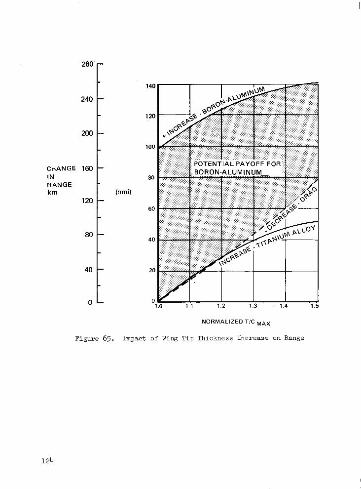
280'
240
200
CHANGE 160 I N RANGE krn
120
80
40
0
(nrni)
NORMALIZED T/C MAX
Figure 65. Impact of Wing Tip Thickness Increase on Range
REFERENCES
1. Sakata, I. F.; and Davis, G. W . : Subs t an t i a t ing Data f o r Arrow-Wing Supersonic Transport Configuration Structural Design Concepts Evalua- t i o n . NASA CR-132575-1, -2, -3, -4, October 1976.
2. Sakata, I. F.; Davis, G. W . ; Robinson, J. C . ; and Yates, E. C . Jr.: Design Study of S t ruc tura l Concepts for an Arrow-Wing Supersonic- Cruise A i r c r a f t . AIAA Paper No. 75-1037, AIAA 1975 A i r c r a f t Systems and Technology Meeting, Los Angeles, California, A u g u s t 4-7, 1975.
3. Van Hammersveld, John: P roduc ib i l i t y Technology Studies - Supersonic Cruise Aircraf t . 21s t Nat iona l SAMPE Symposium and Exhib i t ion , Los Angeles , Cal i fornia , Apri l 6-8, 1976.
4. FOSS, R. L.; Zalesky, R . E.: Studies of the Impact of Advanced Tech- nologies Applied to Supersonic Transport Aircraft. NASA CR-132618, April 1975.
5. McCulloch, A . J . ; Melcon, M. A . ; and Young, L.: Fatigue Behavior of Sheet Material for the Supersonic Transpor t . Am-TR-64-399, Volume I, Lockheed-California Company, January 1965.
6. "Equations , Tables, and Charts for Compressible Flow," NACA Report 1135, 1953.
7. "U.S. Standard Atmosphere, 1962," U.S. Government P r in t ing Of f i ce , Washington, D . C . , December 1962.
8. Albano, E . and Rodden, W. P.: A Doublet-Lattice Method fo r Ca lcu la t ing L i f t D i s t r ibu t ions on Osc i l la t ing Sur faces in Subsonic Flows. AIAA Journa l , V d u m e 7, February 1969, pp. 270-285; Errata, A I M Journa l , Volume 7 , November 1969, p . 2192.
9. Pines , S . , Dugundji, J . , and Neuringer, J . : Aerodynamic F l u t t e r Derivat ives for a F lex ib l e Wing with Supersonic and Subsonic Edges. Journal of Aeronaut ical Science, Vol. 22, 1955, pp. 693-700.
10. Hassig, H. J.: An Approximate True Damping So lu t ion o f t he F lu t t e r Equation by Determinate I teration. Journal of A i r c r a f t , Volume 8, November 1971, pp. 885-889.
11. R . F. OfConnell , H. J. Hassig; and N . A. Radovcich: Study Of F l u t t e r Related Computational Procedures for Minimum Weight S t r u c t u r a l S i z i n g of Advanced A i r c r a f t . NASA CR-2607 , March 1976.
12. Lange, R . H . ; Sturgeon, R. F.; Adams, W. E. ; Bradley E. S.; Cahi l l , J. F.; Eudaily, R. R . ; Hancock, J. P.; and Moore, J. W.: Study of the Application of Advanced Technologies t o Long-Range Transport Aircraft. NASA CR-112088 ( C ) , Apr i l 1971.
NASA-Langley, 1977 CR-2667