nasa technical note · nasa technical note ... specific flywheel design example ... for the...
TRANSCRIPT
N A S A TECHNICAL NOTE
RIM-SPOKE COMPOSITE FLYWHEELS -STRESS A N D VIBRATION ANALYSIS
Christos C. Chdn2is und Louis J. KiruLy
Lewis Reseurch Center Cleveland, Ohio 44135
N A T I O N A L AERONAUTICS AND SPACE A D M I N I S T R A T I O N W A S H I N G T O N , 0. C. NOVEMBER 1976
https://ntrs.nasa.gov/search.jsp?R=19770004499 2018-06-09T14:37:19+00:00Z
--
TECH LIBRARY KAFB,NM
--1. Report No. 2. Government Accession No.
NASA T N D-8339 _._ .... 4. Title and Subtitle
RIM-SPOKE COMPOSITE FLYWHEELS - STRESS AND VIBRATION ANALYSIS
_ _ 7. Authods)
Chris tos C. Chamis and Louis J. Kiraly
9. Performing Organization Name and Address
Lewis Research Center National Aeronautics and Space Administration Cleveland, Ohio 44135
2. Sponsoring Agency Name and Address
National Aeronautics and Space Administration Washington, D. C. 20546
5. Supplementary Notes
-.
3. Recipient’s Catalog No.
5. Report Date November 1976
6. Performing Organization Code
8. Performing Organization Report No.
E -8657 10. Work Unit No.
506-17 1 1 . Contract or Grant No.
13. Type of Report and Period Covered
Technical Note 14. Sponsoring Agency Code
Elementary relations a r e used to determine the mater ia l utilization efficiency of a thin-wall r i m composite flywheel over other configurations. An algori thm is generated for the automatic selection of the optimum composite mater ia l for a given thin-rim flywheel environment. Subsequently, the computer program NASTRAN is used to per form a detailed stress and vibration analysis of thin-wall cylindrical-shell r im-spoke single- r i m and mult i r im composite flywheels fo r a specific application.
- ..- _.~~. _- ~
7. Key Words (Suggested by Author(s)) 18. Distribution Statement
Composite mater ia l s ; Fly wheels; Energy Unclassified - unlimited s torage; S t r e s s analysis ; Mechanical en- STAR Category 39 gineering; Vibrational stress
9. Security Classif. (of this report) 20. Security Classif. (of this page)
Unclassified Unclassified -~ . _ .. -.
*For sa le by the Nat ional Techn ica l Information Service, Spr ingf ie ld, V i rg in ia 22161

RIM-SPOKE COMPOSITE FLYWHEELS - STRESS AND VIBRATION ANALYSIS*
by Chr is tos C. Chamis a n d Louis J. K i ra l y
Lewis Research Center
SUMMARY
Elementary relations are used to determine the material utilization efficiency of a thin-wall r im composite flywheel compared with other configurations. An algorithm was generated for the automatic selection of the optimum composite material for a given thin- r im flywheel environment. Subsequently, the computer program NASTRAN was used to perform a detailed stress and vibration analysis of both single and multiple r im thin-wall cylindrical-shell rim-spoke composite flywheels for a specific application.
Preliminary results indicate that the flywheels investigated can be used to s tore power from a wind turbine generator and deliver it at the rate of 10 kilowatts for 4 days during which low winds prevent power generation from the turbine. The thin cylindrical r im is the most weight-efficient basic-element flywheel configuration for composites. Multirim flywheels combine both weight- efficient and volume efficient r ims to optimize the total energy capacity of a single flywheel installation. NASTRAN can be used for the detail stress and structural dynamics analysis of both single and multirim f l y h e e l s .
INTRODUCTION
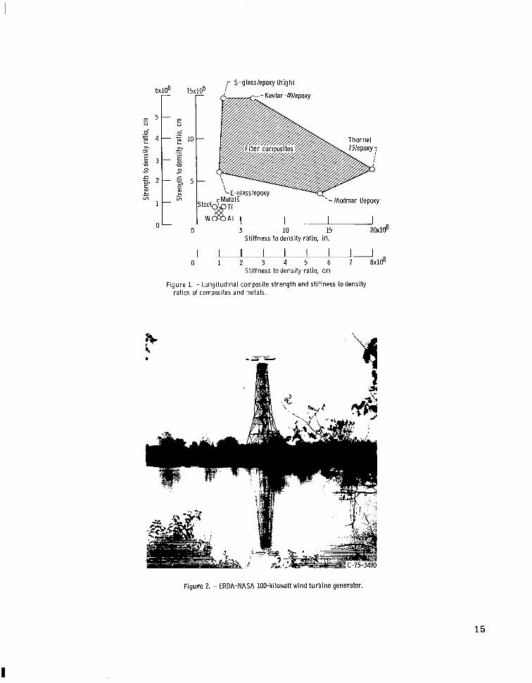
The use of fiber composite materials in flywheels offers several advantages over metal flywheels. The major advantages result primarily from the high longitudinal specific strength (strength/density) and high longitudinal specific stiffness (modulus/ density) of composites compared with metals. Additional advantages offered by composites are (1) a large number of composites are available with a wide range of mechanical properties (fig. 1) from which selections can be made to meet diverse design requirements, (2) various flywheel configuration can be readily fabricated using the extensively developed filament winding capability that already exists, and (3 ) less material is required for containing flywheel bursts (reduced fragment kinetic energy).
Of the various composite flywheel configurations possible, the thin-wall cylindrical-
* A summary of this report was presented at the 1975 Flywheel Technology Symposium, Berkeley, Calif., Nov. 10-12, 1975.

shell rim-spoke configuration appears to utilize composites most efficiently. The distinct advantages of this configuration a r e
(1)The r i m is st ressed primarily in the hoop direction in a centrifugal force field. (2) The r i m can be fabricated using hoop windings only. (3) The thickness of the r i m can be selected to minimize radial stresses resulting
from the fabrication process (winding, thermal, and phase -change shrinkage) and the centrifugal forces.
(4) The spokes can be sized to undergo radial deformation equivalent to that of the r im . For example, the spokes can be made from the same composite material, but with a pseudoisotropic laminate configuration. This will ideally yield a spoke modulus of one-third that of the hoop, which is the required condition for equivalent radial deformation. Equal radial spoke-rim deformation eliminates stress concentrations at the spoke-rim junction and the resulting induced bending in the r i m (in lieu of designing a radially sliding joint between spoke and r im).
(5) The concept is easily adaptable to multirim composite flywheels with specified clearance between r ims .
Because the thin r ims are in essence thin-wall cylindrical shells, they a r e readily susceptible to vibrate in one or more of their many natural frequencies within the wide range of flywheel operational rotation speeds (excitation frequencies). To a s ses s the suitability of the composite thin-wall cylindrical-shell configuration in a flywheel environment, the vibration resistance of these configurations in the presence of a centrifugal force field needs to be determined. Therefore, an important objective of the present investigation w a s to perform detailed stress and vibration analyses of the thin-wall cylindrical- shell rim-spoke composite flywheel using NASTRAN to demonstrate
(1)The adequacy of the thin-wall cylindrical-shell composite rim-spoke configuration for a specific flywheel application
(2) The usage of available structural analysis tools to a s ses s the potential vibration problem that might a r i se in such flywheels
Secondary objectives of the present investigation were (1)the demonstration of hoop-wound thin-rim superiority over other basic element flywheel configurations, (2) the selection of optimum composite material, and (3) the determination of the bounds on thin-rim wall thickness for negligible radial stresses.
SPECIFIC FLYWHEEL DESIGN EXAMPLE
The specific flywheel application investigation was for energy storage during calm o r low wind conditions for a wind-turbine generator (such as shown in fig. 2) having the following assumed design requirements:
2
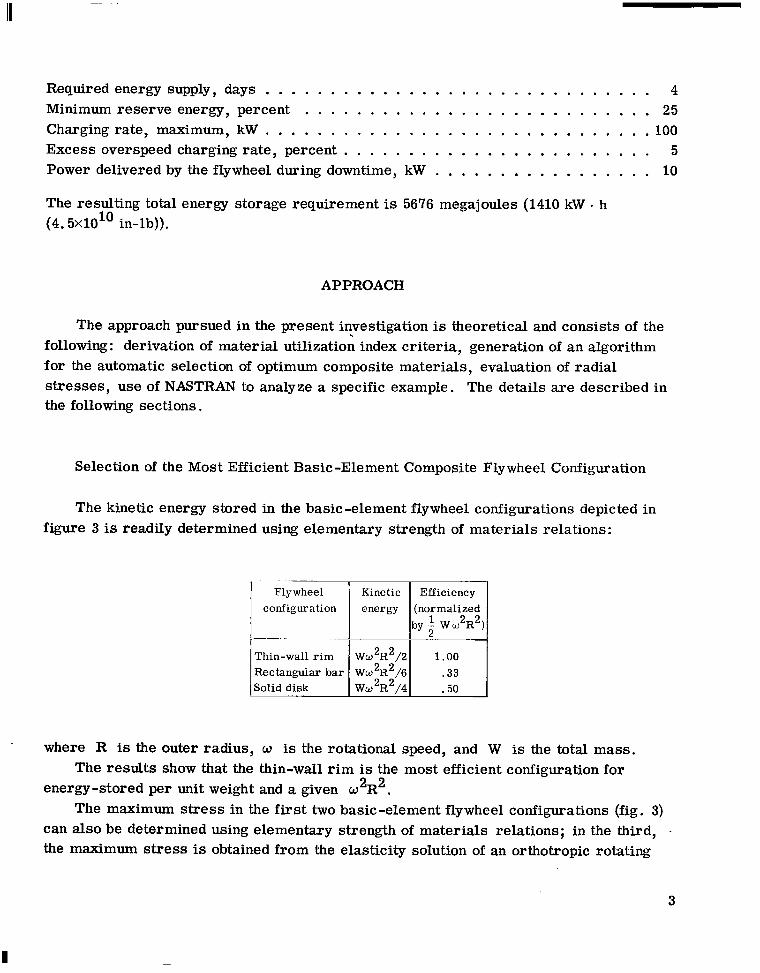
Required energy supply, days . . . . . . . . . . . . . . . . . . . . . . . . . . . . . . 4 Minimum reserve energy, percent . . . . . . . . . . . . . . . . . . . . . . . . . . . 25 Chargingrate, maximum, kW . . . . . . . . . . . . . . . . . . . . . . . . . . . . . . l o 0 Excess overspeed charging rate, percent . . . . . . . . . . . . . . . . . . . . . . . . 5 Power delivered by the flywheel during downtime, kW . . . . . . . . . . . . . . . . . 10 The resulting total energy storage requirement is 5676 megajoules (1410 kW h
(4. 5X1O1O in-lb)).
APPROACH
The approach pursued in the present investigation is theoretical and consists of the following: derivation of material utilization index criteria, generation of an algorithm for the automatic selection of optimum composite materials, evaluation of radial stresses, use of NASTRAN to analyze a specific example. The details are described in the following sections.
Selection of the Most Efficient Basic-Element Composite Flywheel Configuration
The kinetic energy stored in the basic-element flywheel configurations depicted in figure 3 is readily determined using elementary strength of materials relations:
Flywheel Kinetic Efficiency energy (normalized
by-1 W W2 2R ) 2
Thin-wall r im Ww2R2/2 1.00 Rectangular bar Ww2R2/6 . 3 3 Solid disk Ww2R2/4 .50
. where R is the outer radius, w is the rotational speed, and W is the total mass. The results show that the thin-wall r i m is the most efficient configuration for
Renergy-stored per unit weight and a given w 2 2 . The maximum stress in the first two basic-element flywheel configurations (fig. 3)
can also be determined using elementary strength of materials relations; in the third, the maximum stress is obtained from the elasticity solution of an orthotropic rotating
3
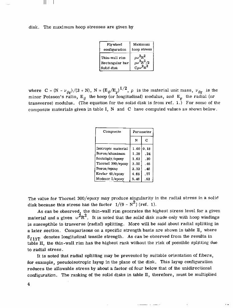
disk. The maximum hoop stresses are given by
I
Thin-wall rim Rectangular bar Solid disk
where C = (N - ver ) / (3 + N), N = (Ee/Er)1/2, p is the material unit mass , ver is the minor Poisson's ratio, Eo the hoop (or longitudinal) modulus, and Er the radial (or transverse) modulus. (The equation for the solid disk is from ref. 1.) For some of the composite materials given in table I, N and C have computed values a s shown below,
Composite I Parameter -
N C ~ ~ -
Isotropic material 1 .00 3.18 Boron/aluminum 1 .29 .24 Scotchply/epoxy 1.63 .30 Thornel 300/epoxy 3.00 .46 Boron/epoxy 3.33 -48 Kevlar 4g/epoxy 4.66 .57 Modmor I/epoxy 5.48 .62-
The value for Thornel 300/epoxy may produce singularity in the radial s t r e s s in a solid disk because this s t r e s s has the factor 1/(9 - N 2 ) (ref. 1).
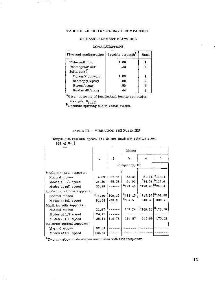
A s can be observed, the thin-wall r i m generates the highest s t r e s s level for a given material and a given o R2 2 . It is noted that the solid disk made only with hoop windings is susceptible to tranverse (radial) splitting. More will be said about radial splitting in a later section. Comparisons on a specific strength basis are shown in table It, where
'2 11T denotes longitudinal tensile strength. A s can be observed from the resul ts in table 11, the thin-wall r i m has the highest rank without the r i sk of possible splitting due to radial stress.
It is noted that radial splitting may be prevented by suitable orientation of fibers, �or example, pseudoisotropic layup in the plane of the disk. This layup configuration reduces the allowable stress by about a factor of four below that of the unidirectional configuration. The ranking of the solid disks in table 11, therefore, must be multiplied
4

by four, which resul ts in a rank of eight for a solid disk of Scotchply/epoxy relative to the thin-wall r im .
The important conclusion from the previous discussion is that the hoop-wound thin-wall r i m is the most weight efficient basic-element flywheel configuration for composite s .
Criteria for Sizing Spokes in Thin-Wall RimSpoke Composite Flywheels
Criteria for sizing spokes in thin-wall rim-spoke composite flywheel configurations may be derived by requiring that the radial deflection of the spoke equal the radial deflection of the r im. When this condition is satisfied, the following are also true: (1)the r im spoke system is statically determinate; (2) the s t resses and deflections in the spokes and the r im are easily determined using elementary strength of materials relations; and (3) the spokes, fixed to the r im , do not induce bending in the r im because of differential radial expansion.
The resulting criterion for meeting the above condition in equation form is
where ErS is the spoke modulus in the radial direction, ps is the spoke density, EBR is the r i m modulus in the hoop direction, and pR is the r i m density. Therefore, a variety of choices a re available to meet this criterion. A unique choice is to make the spoke from the same composite material as the r i m but with a pseudoisotropic laminate configuration. The simplest pseudoisotropic laminate configurations a r e of the following type: [0, *6OIs, [0, 9O*45Is, or even random orientation. The inplane modulus of the pseudoisotropic laminates is one -third of the longitudinal modulus. For example, the pseudoisotropic modulus of boron/epoxy (table I) ic about 6. 7X10¹⁰ pascals( 9 . 7 ~ 1 0 ~ ~psi) and that of Kevlar-49/epoxy is 2. 8X10¹⁰ pascals (4.lXlO 6 psi).
The important conclusions from this discussion are that (1)cri ter ia are easily derivable for sizing spokes and (2) a spoke made from the same composite as the r im but with pseudoisotropic layup satisfies the cri terion for equal radial displacement in the r i m and the spoke.
OPTIMAL MATERIAL SELECTION
Rim material selections were made using a computerized algorithm for multirimmed flywheel designs. Basically, the algorithm acts to choose each r i m in such a
5

Illll I l l I l l I I I l l1 I I
way as to maximize the total energy storage of the flywheel. This approach resul ts in hoop s t r e s s levels approaching the strength capacity of the material in each r im .
A candidate materials list was used for material selection. The algorithm acts to select materials from this list on a r i m by r i m basis. The use of a candidate materials list allows definition of a wide range of possible materials. Furthermore, the use of such a list allows us to apply external constraints on material selection. For example, if environmental aspects o r economic constraints were a factor, only those materials that satisfied these constraints would be included in the list. In this study the list contained several available high strength to weight ra t io composites (table I), high strength steel alloys, and even lead. No further attempt was made to optimize the materials catalogued.
Calculation of the energy stored in a rotating r i m leads to two expressions reflecting the energy storage efficiency of a given r im . The rotary inertia I, the radial displacement u, the hoop stress So, and the energy stored in a r i m T , a r e related by
u = R k )
and
1T = - I o 2 2
where h, t , p , and R are, respectively, the r i m height, thickness, mass density, and the midplane radius; and where w represents the rotary speed. The energy storage is maximized when the hoop s t r e s s S o becomes equal to the fracture stress in the r im.
The volume and weight efficiency indices of a r im may now be expressed, respectively, as
6
and
2
(7)
These expressions lead us to the conclusions that (1)The volume index of a r i m is maximized with the highest strength material, re
gardless of weight. (2) The weight index of a r i m is maximized with the highest strength to weight ratio,
regardless of the strength alone. An installation efficiency index may now be defined for the practical implementation
of a multirimmed flywheel. The installation index is a measure of the energy storage potential within a given flywheel containment. Rims reflecting both high volume indices and high weight indices a r e used for maximum installation efficiency index. Fo r example, consider a high weight index r im operating at fu l l capacity and designed to f i t within some radius. The high weight index outer r im would be constructed using a material with a high strength-to-weight ratio (i.e. , a composite). Within the outer r im we may construct a high volume index r im using a stronger but denser material (i.e . , maraging steel). The energy storage capacity of the installation is therby increased.
Multirimmed flywheel materials are selected to maximize the installation index by the computer algorithm. The computer program flow chart for this algorithm is depicted in figure 4. In addition to selecting the optimum r i m material, the computer program acts as a preprocessor and generates the required NASTRAN input bulk data deck. We begin by defining the materials list, a maximum r im radius, a thickness to radius ratio, number of r i m s to be used, and the total energy to be stored. The highest strength-to-weight ra t io material is selected for the outer r im , and the maximum rotational speed is calculated to fully load this material in hoop stress. The r i m thickness, energy, and weight per unit height are calculated. If more r i m s need to be selected, the strength requirements at the next r i m radius are determined and the most dense material satisfying the strength limitation is selected for the next r im. If the radial expansion of the current r i m under loading is less than that of the previous (outer) r im, the condition is identified (so the NASTRAN preprocessor can generate a se t of multiple point constraints between the r ims) . When all of the r i m s have been selected, the height of the flywheel as well as the resultant weight is calculated to meet the energy storage requirement. If the result is satisfactory, the required NASTRAN input bulk data deck is generated.
This algorithm was applied to a single r i m and a 25-rim design. Specific cases of each type were examined using NASTRAN.
7
I

I-.! I1 I I I I 1 I
NASTRAN APPLICATION
The output of the material selection algorithm is used to generate the required NASTRAN input bulk data deck for all the r ims . Each r i m is modeled as a ser ies of quadrilateral (CQUAD2) NASTRAN elements with centrifugal radial force loads applied (fig. 5). Rims that radially interfere at operational speed a r e identified and a set of multiple point constraints a r e applied at their boundaries. Selected r i m materials a r e referenced and each of the r i m s a r e located in f ree space using NASTRAN single-point constraints instead of supporting spokes. Spokes of appropriate proportions were added later to study spoked flywheel cases (fig. 6).
The two designs selected for further study represent a single-rim design and a multir im design that appear to be of reasonable proportions for construction. Each design was studied in two configurations: (1)Rim flywheel with spokes and (2) r im flywheel without spokes. The four resulting configurations were then studied for s t r e s s and displacements in each of the following cases: (1)static analysis, (2) f ree vibration modal analysis, and (3) f ree vibration modal analysis with structural stiffening due to centrifugal and gravity loads.
Additional analysis was undertaken to determine stiffened mode vibrations for the flywheels at one-half of the rated speed. Limited studies of the effects of a concentrated mass and the change of vibration characteristics with changing r i m thickness were also made.
Our goals with these cases were to (1)Determine the characteristics of thin rim-spoke composite superflywheels
(a) Modal characteristics (b) Radial deformation
(2) Identify the modal vibrations near the operating speeds of the flywheels (3) Establish the numerical procedures for the analysis and design of a multirim
superflywheel installation
APPLICATION TO TWO SPECIFIC DESIGNS
Design Selection
The results of the computerized selection algorithm a r e plotted for families of single and multirim designs in figure 7. The single-rim and 25-rim flywheel designs a r e constrained by a r i m thickness to radius ratio of 0.12, the unoptimized materials list, and a total energy storage requirement of 6120 megajoules (1410 kW h (4.5X10 10
in-lb)). Two designs selected for further study represented reasonable operating levels and proportions for construction. The selected designs are shown schematically in
8

figure 8. In this figure the basic properties and relative s izes of the single and multir im cases are identified.
The single-rim design is much lighter and much la rger than the multirim design. The single rim represents a minimum weight condition, while the multirim design represents a maximum energy storage per containment size. Since the first five r ims of the multirim design s tore 75 percent of the total energy, only these r i m s were included in the detailed NASTRAN analysis of stress and vibration.
Modal vibration frequencies for the two designs are summarized in table III. Modal vibrations are included for the r i m s alone and for the r i m s with spokes under both unloaded and centrifugally loaded conditions and at full and half speed operation. The central shaft of the flywheel assembly is considered to be infinitely rigid in all cases . In general, the resultant modal frequencies tended to reduce with the addition of spokes o r with lower operating speeds. In the multirim case the frequencies listed correspond with a single r i m (or rim-spoke assembly), which can vibrate independently of the rest of the structure. The addition of shaft compliance would have coupled this vibration to the rest of the flywheel structure.
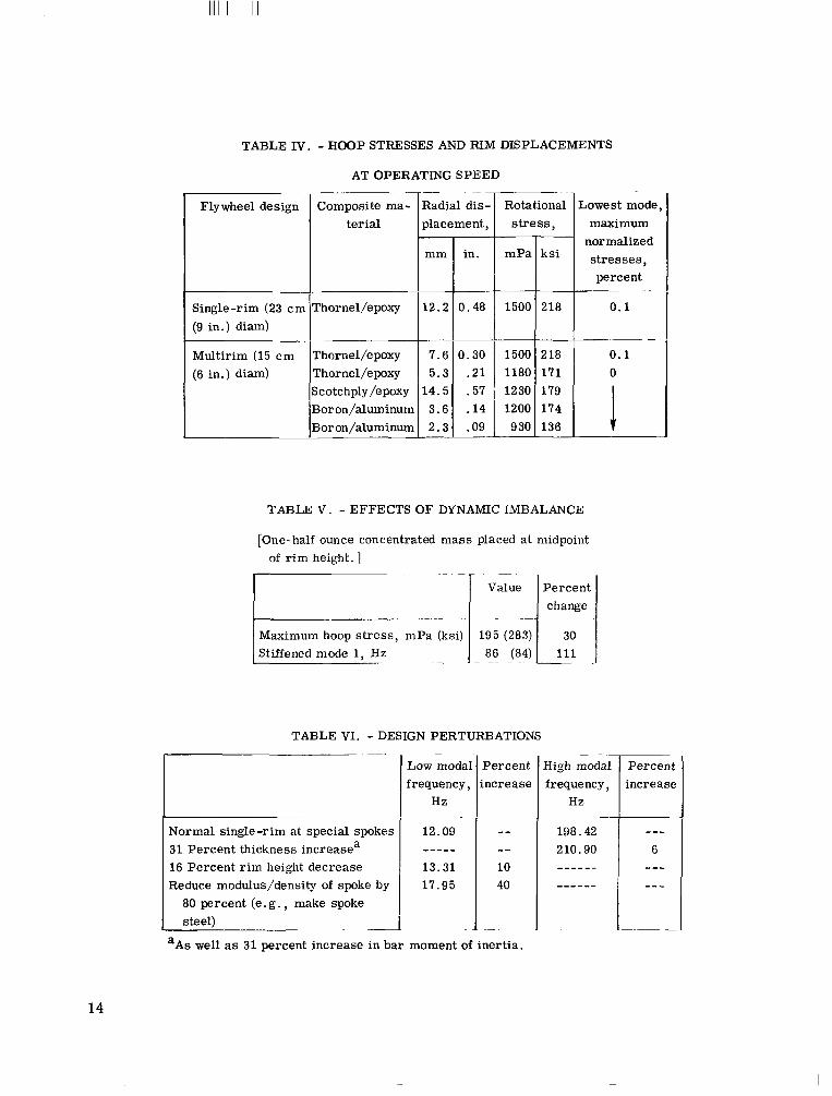
The NASTRAN static stress analysis resul ts for each r i m are included in table IV, in which the stress levels and radial displacement of each r i m at f u l l operating speed are shown. In both design cases the flywheel is sized and operated to load the outermost r i m to its strength capacity. When the amplitude of the lowest modal vibration is normalized to the steady -state radial deflection, the relative contributions of vibration stresses become the percentage values identified in the last column of table IV.
Dynamic Imbalance
The effects of a dynamic imbalance were briefly investigated for the single-rim design. The resul ts are shown in table V. A 14.2-gram (1/2-0z) concentrated mass placed midway to the r i m height increased the peak hoop stresses by 30 percent and increased the lowest modal vibration frequency 111percent.
Perturbations of Design Parameters
A set of perturbations on the geometry design parameters were also run to briefly determine the effects of changing various aspects of the total design. The resul ts (shown in table VI) indicate that modal frequencies may be controlled by changing sets of design parameters. In particular, we note that modal frequencies increase with increasing r i m thickness, decreasing r i m height, o r increased rim-spoke interference. The results of the design perturbations are presented only as an indication of possible
9
I
parametric variations associated with this flywheel design, and may not be representative of rim-spoke flywheels in general.
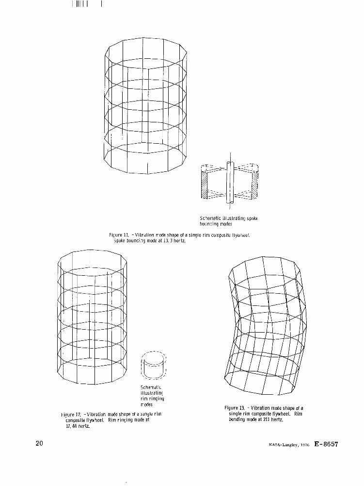
VIBRATION MODE SHAPES
Modal Response
Modal responses are plotted in figures 9 to 13. These modal responses are generally represented as (1) r i m bending modes, (2) bar bouncing modes, or (3) r i m ringing modes. The r i m ringing and bar bouncing modes are characterized by radially symmetric motions of the structure, and thus appear to cause minimal problems during operation. The bending modes, however, ac t to asymetrically redistribute the r im mass with time. These r o d e s a r e the most dangerous in the high rotary fields of an operational flywheel.
The bending mode vibrations do not occur in the operating ranges of the flywheels studied. However, more analysis for a finalized flywheel installation would be required. Detail design of a final flywheel structure requires that bending modes be identified and the flywheel be designed to decrease the probability of these modes in the operating range. Also, the possibility of subharmonic or superharmonic excitation should be carefully examined for these potentially destructive modes.
It appears that the r i m bending modes can be most readily controlled by using more than two spokes at either end of a r im . This would decrease pivoting of the shell ends about the spoke.
SUMMARY OF RESULTS
The following major results were obtained from an investigation of the stress and vibration analyses of rim-spoke composite flywheels:
1. The hoop wound thin wall cylindrical r i m is the most weight-efficient basic-element flywheel configuration for fiber composites.
2 . Cri ter ia are easily derivable for sizing spokes for rim-spoke flywheel. Spokes made from the same composite as the r im but with pseudoisotropic laminate configuration (ply layup) satisfy the criterion for each radial displacement in the r i m and the spoke.
3. Multirim flywheels combine both weight efficient and volume efficient r i m s to optimize the total energy capacity of a single flywheel installation.
4. NASTRAN can be used for the detailed stress and vibration analysis of single-rim and multirim thin-wall cylindrical-shell rim-spoke composite flywheels. On a prelim
10
I
inary design basis, the flywheel ivvestigated can supply power during periods of low wind fo r 4 days at a power rate of 10 kilowatts.
5. Lewis developed multirim computer programs a r e effective in selecting optimal r i m materials and in generating NASTRAN input bulk data decks for detailed analysis.
CONSIDERATIONS FOR FURTHER STUDY
The a reas where further work is needed for the detailed design of multirim super flywheels are :
1. Selection of materials specifically chosen to optimize maximum r i m strength to weight ratio and r im to r i m compatibility
2 . Investigation of filament winding techniques resulting in continuously variable strength and density r i m s (by variation of the filament to volume ratio). This technique would allow thicker r i m s with continuous mass density variation along the r im radius to optimize energy storage
3 . Evaluation of subharmonic and superharmonic excitation of the potentially destructive r im bending vibration modes
4. Application of autobalancing devices/techniques to high speed flywheels.
Lewis Research Center, National Aeronautics and Space Administration,
Cleveland, Ohio, June 506-17.
REFERENCE
1. Lekhnitskii, S. G. : Anisotropic Plates . Gordon and Beach, 1968.
11
I

----
---
----
--
I
Fiber Density Thermal coefficient volume
ratio
Boron/epoxy AVC05505 0.50 Boron/polyimide WRD9371 .49 Scotchply/epoxy 1009-26-5901 .72 Modmor L/epoxy ERLA4617 .45 Modmor I/polyimide WRD 9371 .45 Thornel 300/epoxy NARMCO 5208 .70 Kevlar 49/epoxy CE-3305 .54 Boron/aluminum 6061-T6 .50
Longitu- Transdinal verse
30.4 28.4 16.7
1.550 33.3 25.4 22.5
1.357 -2.90 56.3 2.630 3.96 16.2
Modulus Poisson's r a - Longitudinal Transverse Intratio strength strength laminar
Longitu- Transverse Shear - strengthdinal Major Minor Tensile Compres- Tensile Compres
sive sive
-1364 1035 1282
-
836 41.6 195.0 802 21.6
1494 1693 40.1 1179 288 11.0 1480 1713 137.0
-9.10 3.75 6.50
128 8.90 3.15 9.80
42 9.40 4.00
200 220
60 188 215 180
84 216
GPa
22 5 .3 0.17 14 7.6 .16 25 12 .23
7 .1 6 .2 .10 4.9 4.5 . 25
10 6.9 .28 4 .8 2.8 .32
137 .23, 4 1
I l b h 3 I i n / inPF
Boron/epoxy AVC05505 Boron/polyimide WRD 9371 Scotchply/epoxy 1009-26-5901 Modmor I/epoxy ERLA4617 18.5 Modmor I/polyimide WRD 9371 14 .1 Thornel 300/epoxy NARMCO 5208 12.5 Kevlar 49/epoxy CE -3305 Boron/aluminum 6061-T6 ,095 2.20 9 .0
respective values for both SI and U.S. Customary Units.
29.0x10: 32.1
8 .8 3.6 1.74 27.5 1 .03 31.3 26.3 1 .5 12.2 .70 31.5 20.0 , 6.0 216 250 -20.00
------
------ ------- - - - - - - - - - - - - - -
-------
TABLE II. -SPECIFIC STRENGTH COMPARISONS
O F BASIC-ELEMENT FLYWHEEL
CONFIGURATIONS -_.
Flywheel configuration Specific strengtha Rank--~ Thin-wall r i m 1.00 1 Rectangular bar .33 5 Solid disk?
Boron/aluminum 1.00 1 Scotchply /epoxy .80 2 Boron/epoxy .50 3 Kevlar 49/epoxy .44 4-
aGiven in t e rms of longitudinal tensile composite strength, SL 11T'
bPossible splitting due to radial stress.
TABLE III. - VIBRATION FREQUENCIES
[Single-rim rotation speed, 112. 28 Ha: multirim rotation speed, 168.43 Hz.]
-
Modes
Frequency, H z ~
Single r i m with supports: Normal modes 4.69 27.35 53.38 61.15 a113.4 Modes a t 1/2 speed 31.26 55.58 61.02 a74. 58 a127. 6 Modes a t full speed 36.38 a179. 45 a190. 40 a208. 4
Single r i m without supports: Normal modes %'6.36 109.37 a111.15 a145.91 a158.88 Modes a t full speed 91.64 298.6 a301.5 318.4 333.7
Multirim with supports : Normal modes 21.97 _____-157.24 a169. 23 a178. 50 Modes a t 1/2 speed 24.42 Modes a t full speed 25.11 149.76 164.57 165.69 175.52
Multirim without supports: _ _ _ _ _ _ _Normal modes 92.54 Modes a t full speed 149.62 -___----___--
-
aTwo vibration mode shapes associated with this frequency.
13
-- ----- --
------ ------
---
--- ---
I I I I I I I I I I
TABLE IV. - HOOP STRESSES AND RIM DISPLACEMENTS
AT OPERATING SPEED
IFlywheel design Composite ma- Radial dis- Rotational Lowest mode, terial I- placement,I stress, maximum
normalized
I Single-rim (23 c m (9 in.) diam)
II Multirim (15 c m (6 in.) diam)
I'hornel/epoxy rhornel/epoxy ;cotchply/epoxy 3oron/aluminum 3oron/aluminum
-
7.6 0.30 5.3 .21 171
14.5 .57 3.6 .14 2 .3 .09
TABLE V. - EFFECTS OF DYNAMIC IMBALANCE
[One-half ounce concentrated mass placed at midpoint of r im height. 1
~
I Value l ~ e r c e n tI
Stiffened mode 1, Hz
TABLE VI. - DESIGN PERTURBATIONS ~_ - -~ --~
Low modal Percent High modal Percent frequency, increase frequency, increase
Hz Hz -
Normal single-rim at special spokes 12.09 198.42 31 Percent thickness increasea 210.90 6 16 Percent r im height decrease 13.31 10 Reduce modulus/density of spoke by 17.95 40
80 percent (e.g ., make spoke steel) - -A_ _
14
,r S-glasslepoxy (high)
*- Modmar llepoxy -0 5 10 15 20x108
Stiffness to density ratio, in.
I O
Stiffness to density ratio, cm
Figure 1. - Longi tudinal composite strength and stiffness to density ratios of composites and metals.
Figure 2. - ERDA-NASA 100-kilowatt w ind t u r b i n e generator.
15

--
3
/ R J U
(a) Thin-wal l -cyl inder (b) Rectangular bar. (c) Solid disk. r i m .
Figure 3. - Basic-element flywheel conf igurat ions.
NASTRAN card images of candidate materials
>- Candidate materials list and weight per unit height M’
Calculate required height N r ingscompleted? -I and total weight . -~I
I
-1 F u r t h e r study?
I Generate NASTRAN bulk data deck
Output a warn ing flag (CORDZC, CQUARDZ, GRAV, GRID, ( for NASTRAN deck) LOAD, MAT1, MATZ, MPC. PQUADZ
1 SPC. RFORCE) (orewocessor)
Figure 4. - F low cha r t of a lgor i thm for selec!ing rip materials
16

Figure 5. - Finite-element representation. S ing le- r ing flywheel: 72 elements; 84 nodes. M u l t i r i n g flywheels: 60 elements, 72 nodes per r ing; and 300 elements, 360 nodes total.
, 'Y
Single th in -wa l l r i m Five th in-wal l r i m s
Figure 6. - Schematics of flywheel conf igurat ions investigated.
17

20~103
10
r40r
0 1 . 1 . - -1 L50 100 150 200 50 100 150 200
Outer radius, R. cm
IU.J U L I 24 36 48 60 72 24 36 48 60 72
Outer radius, R , in.
(a) Single rim. (b) 25 Rims.
F igure 7. - A l g o r i t h m results.
18

I I1 1111 I 1 1 1 1 1 1 I
I " " " " '
R im Mater ia l Outer radius, R i m thickness Energy cm (in. I c m (in. ) stored
-t
1 Thornellepoxy 91.44 (33.00) 10.97 (4.32) 27.5 182.9 cm 2 Thornellepoxy 81.08 (31.92) 9.73 (3.83) 17.0 (72 in. )
3 Scotchplylepoxy 71.91 (28.31) 8.64 (3.40) 14.0 .1 ..4 B o r o n l a l u m i n u m 63.78 (25.11) 7.65 (3.01) 10.5 5 B o r o n l a l u m i n u m 56.54 (22.26) 6.78 (2.67) 6.5
75.5 - 183 cm 172 in. ) +
(b) Mu l t i r im : 13 r i ngs w i th steel core. Flywheel diameter, 1.83 meters (6 ft); height, 3 meters 110 ftl; total weight, 29 360 kilograms (64727 Ibl; rotational speed, 10 105 rpm. Outer f ive r i ngs analyzed; weight of five r ings, 11761 ki lograms (25 929 Ib).
Figure 8. - Schematics of f lywheel conf igurat ions analyzed.
Figure 9. -V ib ra t i on mode shape of Figure 10. -V ib ra t i on mode shape of a s ingle r i m composite flywheel. s ingle r i m comoosite flywheel. R im R im bending mode a t 99.9 hertz. bending mode, 93.4 hertz.
19
I l l 1 I1 IIIIIII I1 I I
Schematic ilIust rat i ng spoke bouncing modes
Figure 11. -V ib ra t i on mode shape of a s ingle r i m composite flywheel. <poke bouncing mode at 13. 3 hertz.
Schematic i l l us t ra t i ng r i m r i n g i n g modes
F igu re 13. -V ib ra t i on mode shape of a Figure 12 -V ib ra t i on mode shape of a s ingle r i m single r i m composite flywheel. R i m
composite flywheel. R i m r i n g i n g mode at k n d i n g mode a t 211 hertz. 17.44 hertz.
20 NASA-Langley, 1976 E-8657
I1
N A T I O N A L AERONAUTICS A N D SPACE A D M I N I S T R A T I O N
W A S H I N G T O N . D.C. 20546 POSTAGE A N D FEES P A I D
~_ _~ N A T I O N A L AERONAUTICS A N D O F F I C I A L B U S I N E S S SPACE A D M I N I S T R A T I O N
PENALTY FOR PRIVATE USE $300 SPECIAL FOURTH-CLASS RATE 4 5 1 'p1U S M A I L
BOOK J .-?*, *&'..
? a = *.%;&+ .:;;,; . .. .,..- .*- a
1%. il. , I . . .. ' ' .
*. 875 001 C 1 U D 761029 S00903DS DEFT OF THE A I R FORCE AF WEAPONS LABORATORY ATTN: TECHNICAL L I B R A R Y (SUL) K I R T L A N D A F B N M 87'317
: If Undeliverable (Section 158 Postal Mnnnnl) Do Not Return
. ...'>.ir ...- ' I.d
"The aeronaatical and $&e, activities of the United States shall be conducted so as t o contribute , . t o the expansion of human Knowl
..e;..edge of phenomena in the atmosphere and space. T h e Administration,, . I' ,.. . shall provide for the ,wid+ praoticckblti:ad ~ ~ p r o ' ~ ~ ~ ~ ~ ~ ~ ~ s e m i ~ t ~ o n of t!nformt;iq?!flyfGirriing;its ftctivitiej anbfih;tii-e&Zis i%e@eof." :;"'
I .." -AND '&&E : A m OF '1958-' G'~~TION$~.AERONAUTICS * z . r $ ' .*.,,>, I J.
(. . i ...i'. .a t . *
NASA SCIENTIFIC AND TECHNICAL PUBLICATIONS TECHNICAL REPORTS: Scientific and , TECHNICAL TRANSLATIONS: Information technical information considered important, . . published lfi 'a foreign language considered complete, and a lasting contribution to existing knowledge.
TECHNICAL NOTES : Information less broad in scope but nevertheless of importance as a contribution to existing knowledge.
TECHNICAL MEMORANDUMS : Information receiving limited distribution because of preliminary data, security classification, or other reasons. Also includes conference proceedings with either limited or unlimited distribution. -CONTRACTOR REPORTS: Scientific and technical information generated under a NASA contract or grant and considered an important contribution to existing knowledge.
to merit NASA distribution in English.
PUBLICAT1oNS: Information derived from or of value to NASA activities. Publications include final reports of major projects, monographs, data compilations, handbooks, sourcebooks, and special bibliographies.
TECHNOLOGY UTILIZATION PUBLICATIONS : Information on technology used by NASA that may be of particular interest in commercial and other-non-aerospace applications. Publications include Tech Briefs, Technology Utilization Reports and Technology Surveys.
Details on the availability of these publications may be obtained from:
' SCIENTIFIC AND TECHNICAL INFORMATION OFFICE
N A T I O N A L A E R O N A U T I C S A N D SPACE A D M I N I S T R A T I O N Washington, D.C. 20546