nasa technical memorandum 78741 is hoped that the notes presented with equations, and the general...
TRANSCRIPT
NASA Technical Memorandum 78741
(NASA- rll-78741) A BRIEF SURVEY CF ROTARY N78-27085 WTNG I N D U C E D - V E L O C I T Y T H E O R Y { N A S A ) 6 7 p HC h03/KF A01 C S C L 0 1 A
Unclas G3/02 25218
A BRiEF SURVEY OF ROTARY WING INDUCiD-VELOC ITY THEORY
HARRY H, HEYSOK
JUNE 1978
Nat~onal Aeronaut~cs and Space Adminlslratlon
hn~ley Resmch Center Hampton, Virg~nla 23665
https://ntrs.nasa.gov/search.jsp?R=19780019142 2018-06-29T18:51:27+00:00Z
A BRIEF SURVEY OF ROTARY WING INDUCED-VELOCITY THEORY
by Harry H. Heyson
Langley Resecrch Center Hampton, V i r g i n i a 23665
SUMMARY
The development o f m t a r y wing induced-ve loc i ty theory i s t raced from i t s o r i g i n as a momentum-theory est imate of average in te r fe rence , ~ h r o u g h simple vo r tex theory, t o i t s present s ta tus where i t i s i nd i spens ib l e i n c a l c u l a t i n g blade 1 oads . Appl icat ions t o a v . \ r i e t y of i n te r fe rence problems i s demonstra- ted. Wherever poss ib le , experimental r e s u l t s are presented t o conf i rm t he theory.
A1 1 aerodynamic 1 i f t i n g devices, Sncl tiding he1 i copter and autogyro r o to r s , ob ta in t h e i r l i f t as the reac t i on from pus' l ing a i r downward. The momentum thus imparted t o the a i r se ts up an induced f i e l d which i n t e r a c t s o r i n t e r f e r e s t o a s i g n i f i c a n t degree w i t h anything placed near the l i f t i n g system; indeed, i t i n t e r f e r e s w i t h the 1 i f t i n g system i t s e l f .
I n the case o f a he1 i c o p t e r r o t o r , the v e l o c i t i e s induced by the f i e l d in f luence the forces on the blades as they ro ta te ; they a1 t e r t he e f fec t iveness o f t a i l surfaces; and they have powerful fn f luences on the i n t e r f e rence w i t h the add i t i ona l l i f t i n g devices used on a mu1 t i t u d e o f conver t ip lane designs.
The d e t a i l i n which the induced f l ow must be known vz r i es w i t h the intended appl i c a t i o n . A gross o v e r a l l average v e l o c i t y through the r o t o r i s adequate fo r man= performance problems. The spac ia l , time-averaged, f i e l d i s o f t e n adequate t o p r e d ~ c t t a i l ef fec t i veness o r mu tu i l i n t e r f e rence w i t h o ther 1 i f t i n g systems. I f d e t a i l e d load d i s t r i b u t i o n s oveim the blades are requi red, an equa l l y d e t a i l e d kr~owledge o f the instantaneocs induced v e l o c i t i e s along the b l sdes i s required. The d i f f ~ c u ; tjl encountered i n ob ta in ing the requ i red i n f o m a t i o n i s more than proport icnz; t o the d e t a i l requ i red i n the v e l o c i t i e s . I n the s implest cases, the ca l cu l a t i on i s i n c losed Form and occupies th ree o r f o u r l i n e s . I n the more a i f f i c u l t cases, the ca l cu l a t i ons may exceed the capac i t y o f some of the l a r g e s t d i g i i a l conputers.
The p r e s e , ~ t paper attempts t o summarize the s t a t e of knowledge o f r o t a r y - wing f low f i e l d s . I t begins w i t h the simple momentum methobs app l ied t o the r o t o r by b l aue r t . I t then tu rns t o the time-averaged f low f i e l d , where the f i r s t t r l~!y usable r e s u l t s were obtained by Walter Cast les of Georgia Tech. The extens'cc o f Cast le 's work by NACA and a comparison o f the theory w i t h f l ow measuremcnLs 3r t . presefited. F i na l l y , the modern e f f o r t s toward using more d e t a i l e d d;q i t z l r,lethods t o ob ta i n blade-load d i s t r i b u t i o n s are described.

I n most cases, f f gures and equations presented herein, have been abstracted from the o r i g i n a l reports. The notat ion, which var ied from author t o author, i s , therefore, n o t consistent throughout t h i s paper. It i s hoped t h a t the notes presented w i t h equations, and the general context o f the discussion, w i l l suf f ice t o a l low the reader t o i n f e r the proper meanings fo r the symbols throughout the development .
DISCUSS ION - MOMENTUM THEORY - THE AVERAGE INDUCED VELOCITY
Glauert (ref. I ) , i n the ea r l y 19201s, began the development o f r o t a r y wing blade-element theory. I t was c lear from analogous work on prope l le rs and wings t h a t the l oca l angles o f at tack could no t be found so le l y from geometric con- s iderat ions. There must be an interference, o r induced, v e l o c i t y which resul ted from the l ift, and which entered i n t o the angle o f attack equations. No theory o f the time predic ted t h i s induced veloc i ty ; however, the F r 6 ~ 3 momentum theory f o r propel lers i n s t a t i c t h rus t resu l ted i n
where T i s the th rus t , p the mass density o f the f l u i d , R the radius, and the induced ve loc i t y through the d isk (posit 've upward f o r a ro to r ) . On the
o her hand, f o r a wing having a span o f 2R, i t was known tha t the l i f t L was i given by
Glauert noted tha t these two expressions could be combined i n a continuous fashion i f the t o t a l ve loc i t y through the r o t o r d isk was taken as the vector sum o f the induced and forward ve loc i t ies ; t h a t i s , if T $ L
2 = -p"R VR(2wO) (3 )
where VR i s the absolute value of the sum of the induced and forward ve loc i t i es . He appl ied the resu l t i ng value o f wo as a uniform induced ve loc i ty , o r down- wash, over the e n t i r e r o t o r disk. I n terms o f present r o t o r notat ion, where the th rus t c o e f f i c i e n t i s
the i n f l ow r a t i o ( ve loc i t y r a t i o normal t o the d i sk ) i s

and t he advance r a t i o ( v e l ~ c i t y r a t i o p a r a l l e l t o the d isk ; i s
vcos a I J = 7
equat ion (3 ) may be expressed as
Here the c la t ter :?ested f o r about 25 years. Wi th in the usable performance range o f the machines o f those days, such a s imple theory wa: reasonably ade- quate. The f i r s t advances i n r o t o r f l o w - f i e i d theory were no t r e a l l y occasioned b j g rea t known inadequacies i n r o t o r theory as such - ra ther , i t was the need t o est imate downwash angles a t the wings and t a i l s o f unloaded r o t o r con f igu ra t ions . For these purposes, simple momentum concepts were t o t a l l y inadequate, and i t waz necessary t o t u r n t o a t l e a s t a rudimentary v o r t e ~ theory o r i t s equiva lent .
SIMPLE VORTEX THEORY
Work on a simple vo r tex theory f o r r o t o r s was begun dur ing World War I 1 by Coleman, Feingold, and Stempin ( r e f . 2 ) ; however, i t was an 8dd i t i ona l ten yea r t before t h i s work was brought i n t o fu:l f l ower by Castles and De Leeuw ( r e f . 3). ( A mathematical ly d i f f e r e n t , bu t p h y s i c a l l y i d e n t i c a l study was done i n England by Mangler and Squire ( r e f . 4 ) ) .
The Vortex Model
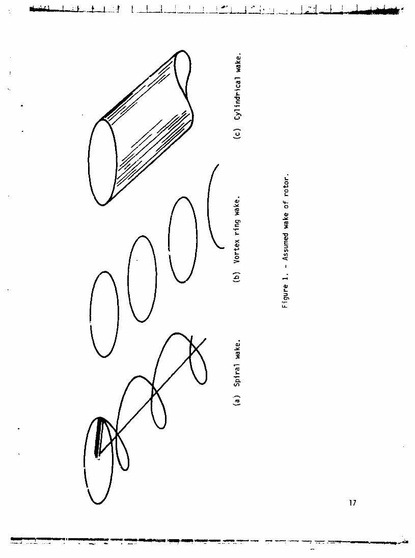
The f i r s t step i n s e t t i n g up a s imple vor tex model i s t o choose a vo r tex pa t t e rn t h a t i s reasonably adequate on a phys ica l basis and, a t the same t ime, s u f f i c i e n t l y simple t h a t numerical r e s u l t s can be ext racted. The wake of a r o t o r i s more complicated than t h a t o f a wing, and a more invo lved model i s required. I f one examines a s ing le-b laded r o t o r , as i n f i gu re 1 (a ) , there would be a bound vor tex along tho blade. A t the r oo t , the f r e e vor tex i s c a r r i e d dohmward by the f l ow through the r o t o r and rearward by the flow past the ro tDr . The t i p vortex i s c a r r i e d o f f i n the same manner, bu t i t a l so i s a f f ec ted by the r o t a t i o n o f the r o t o r ; thus, i t l i e s on a s p i r a l path as shown.
Even t h i s simple s p i r a l i s d i f f i c u l t t o deal w i t h SG the nex t step i s t o d i v i d e the wake vo r t i ces i n t o t h e i r ax is1 and c i r cumfe ren t i a l ~, ,~~ponents and t o d iscard the a x i a l components as being o f secondary importance. The wake then appears as a skewed stack o f vo r tex r i n g s as i n f i g u r e 1 (b ) . The f i n a l step i s t o assume t h a t the r i ngs are spaced so c l o s e l y t h a t they are equ iva len t t o a continuous e l l i p t i c cy l i nde r of v o r t i c i t y as shown i n f i g u r e 1 ( c ) .
The Induced Ve loc i t ies
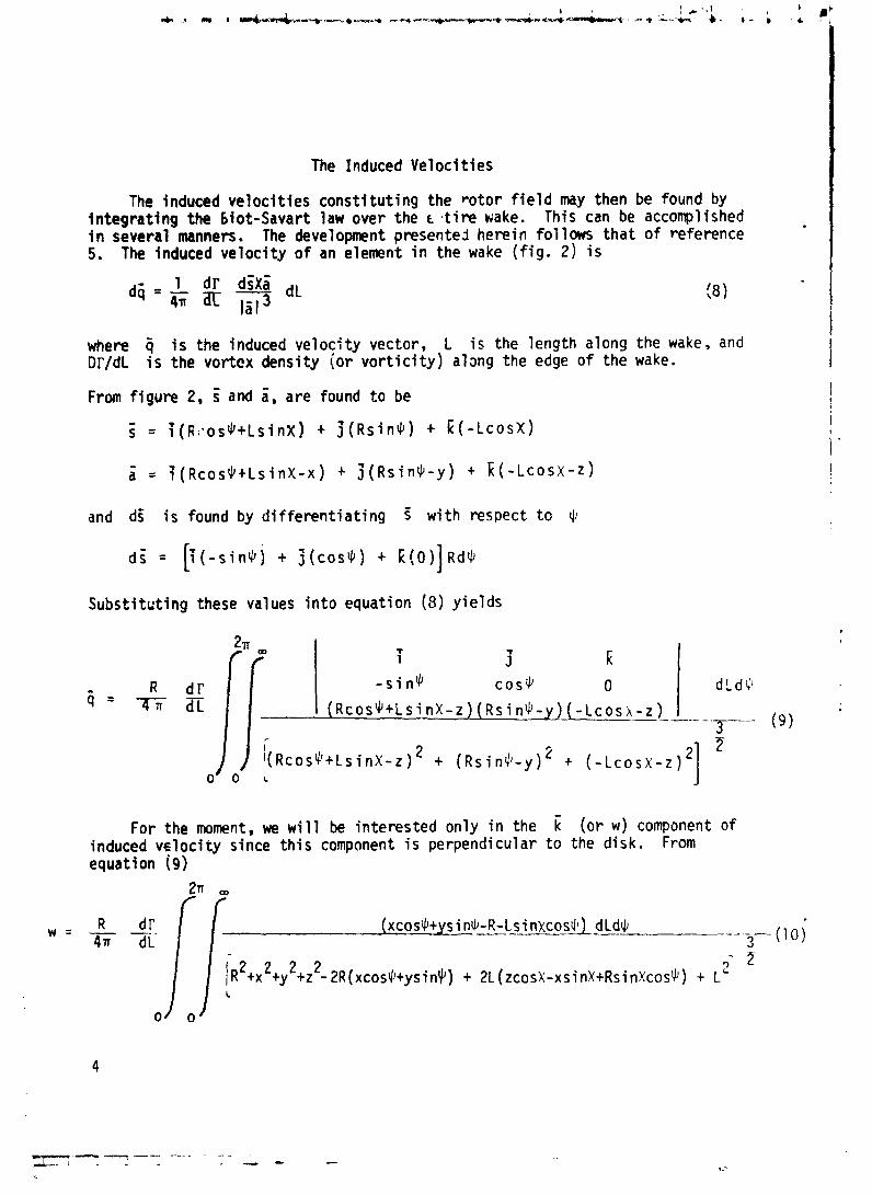
The induced ve loc i t i es cons t i t u t i ng the r o t o r f i e l d may then be found by In tegra t ing the biot-Savart l a w over the c , t i r e wake. This can be accomplished i n several manners. The development presented herein fo l lows t h a t of reference 5. The induced ve loc i t y o f an element i n the wake ( f i g . 2) i s
where i s the induced ve loc i t y vector, L i s the length along the wake, and DT/dL i s the vortex density (or v o r t i c i t y ) alsng the edge of the wake. i I
I
From f i gu re 2, 5 and i , are found t o be i t
and dZ i s found by d i f f e r e n t i a t i n g 5 wi th respect t o rl,
Substi t c t i n g these values i n t o equation ( 3 ) y i e l d s
For the moment, we w i l l be in terested only i n the E (o r w) component of induced v ~ l o c i t y since t h i s component i s perpendicular t o the disk. From equation (9)
2~ m
R d r (xcos$+ysin$-R-Lsi nxcosJ1) dLd$ --- -- -- ----- ( 1 0) 3 - 2 '- 2 ~ ( x c o s $ + ~ s i n ~ ) + 2L (ICOSX-xsinX+Rsin~cosl') t L'
L
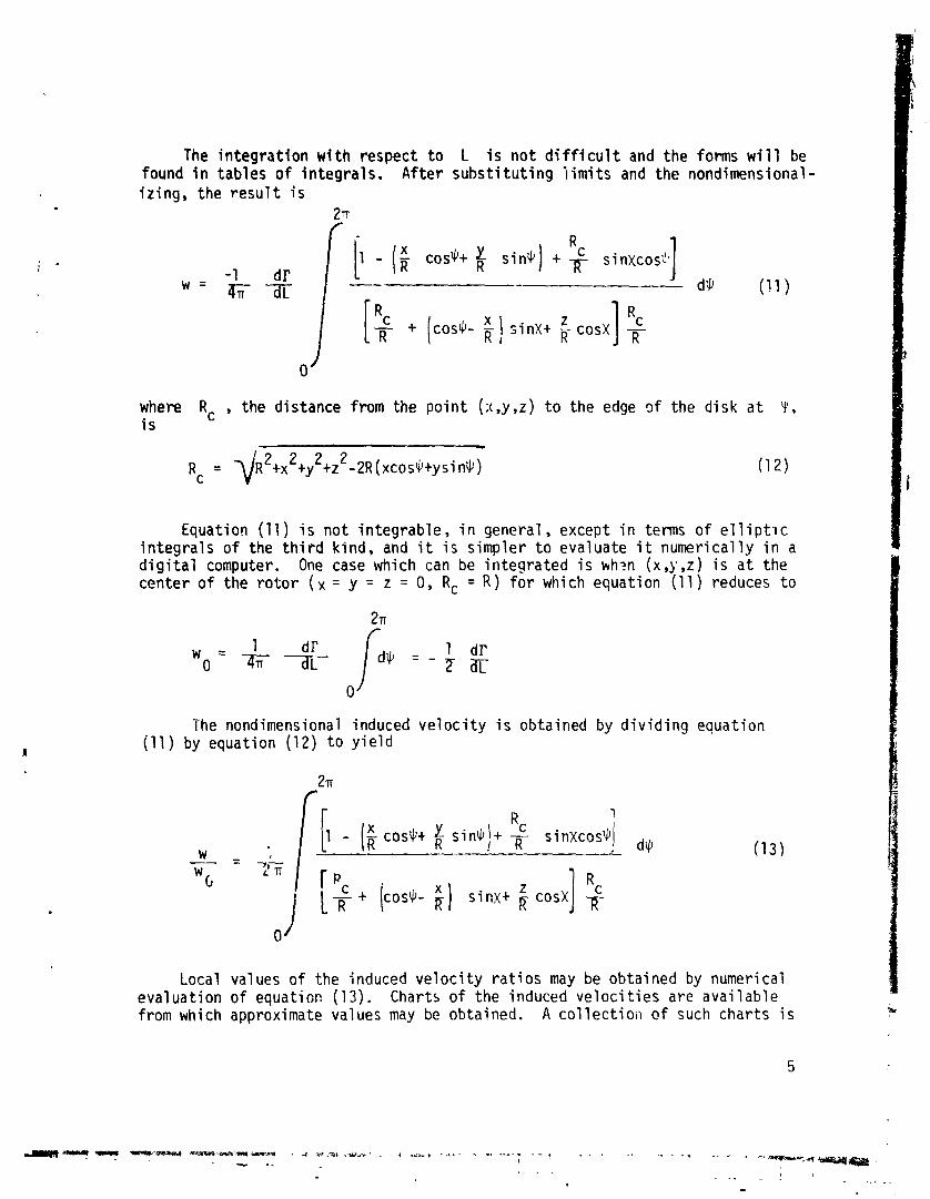
The i n teg ra t i on w i t h respect t o L i s no t d i f f i c u l t and the forms w i l l be found i n tables o f in tegra ls . After subs t i t u t i ng l i m i t s and the nondimensional- i r i n g , the r e s u l t i s
21r f l
where Rc , the distance from the p o i n t (x,y,z) t o the edge of the d isk a t Y ' , i s
Equation (11) i s no t in tegrable, i n general, except i n terms o f e l l i p t i c i n teg ra l s o f the t h i r d kind, and i t i s simpler t o evaluate i t numerical ly i n a d i g i t a l computer. One case which can be in tegra ted i s wh?n (x,y,z) i s a t the center o f the r o t o r ( x = y = z = 0, Rc = R ) f o r which equation (1 1 ) reduces t o
The nondirnensional induced v e l o c i t y i s obtained by d i v i d i n g equation i l l ) by equation (12) t o y i e l d
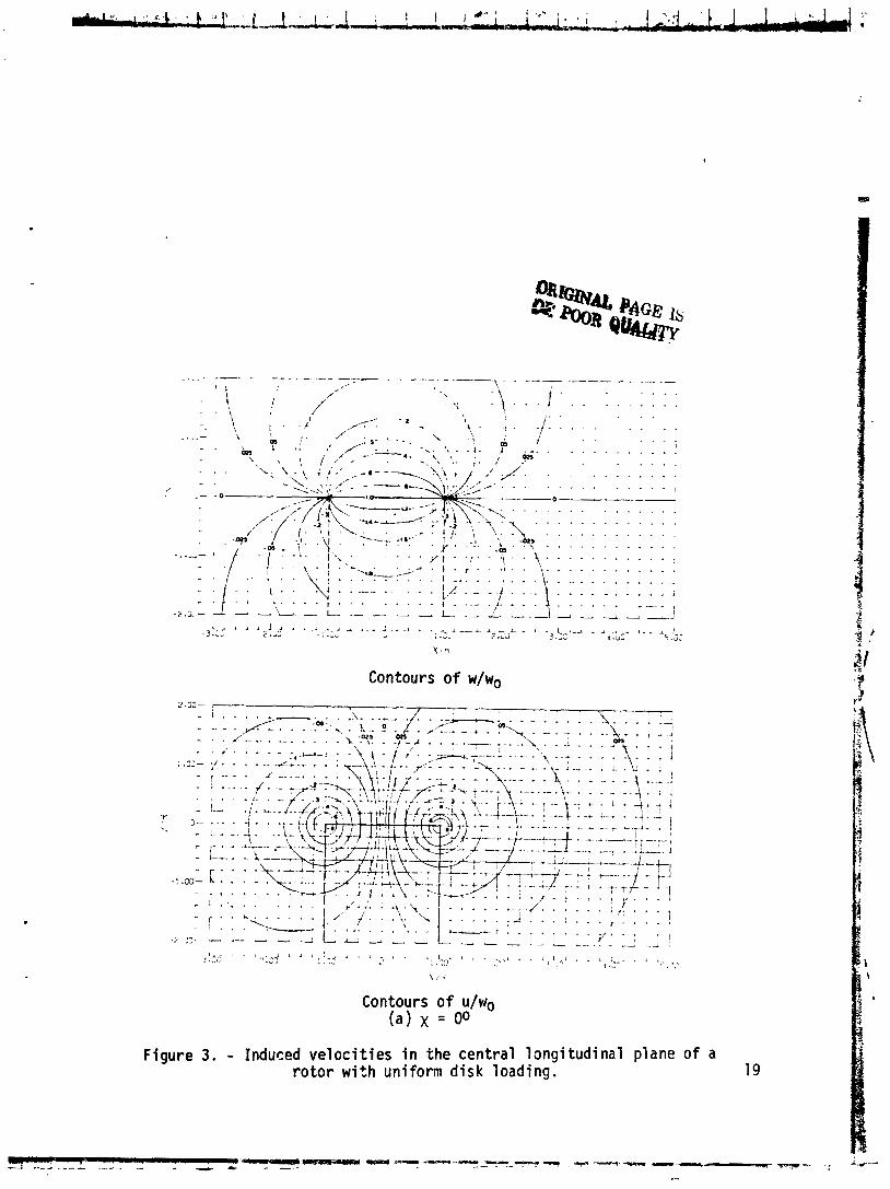
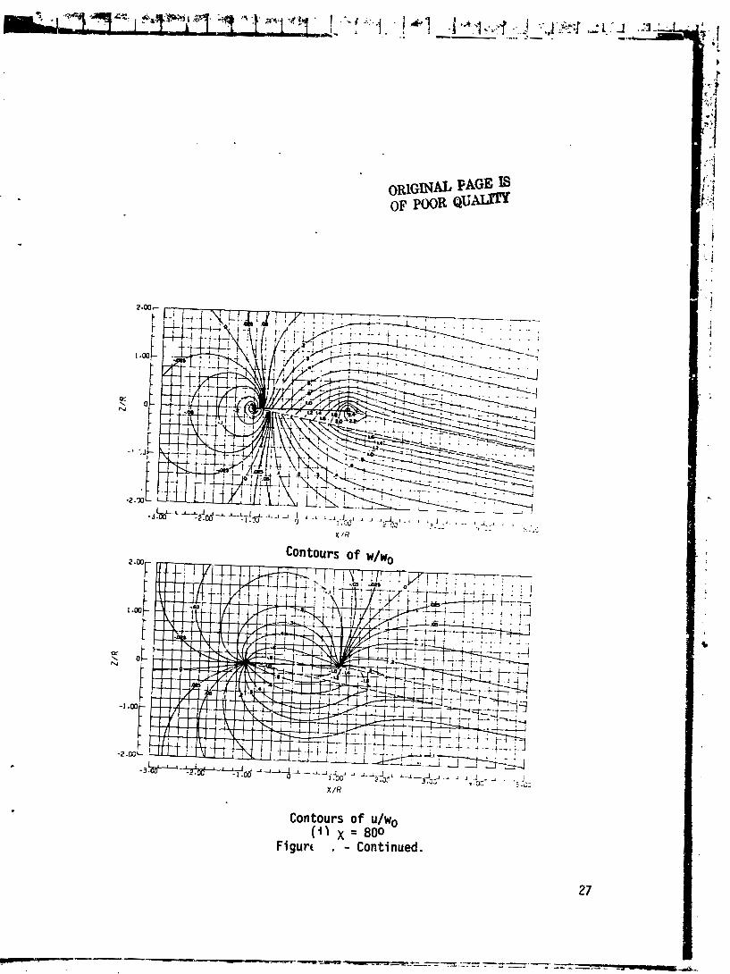
Local values o f the induced v e l o c i t y r a t i o s may be obtained by numerical evaluat ion o f equation (13) . Charts o f the induced v e l o c i t i e s are ava i lab le from which approximate values may bc obtained. A c o l l e c t i o ~ i o f such char ts i s

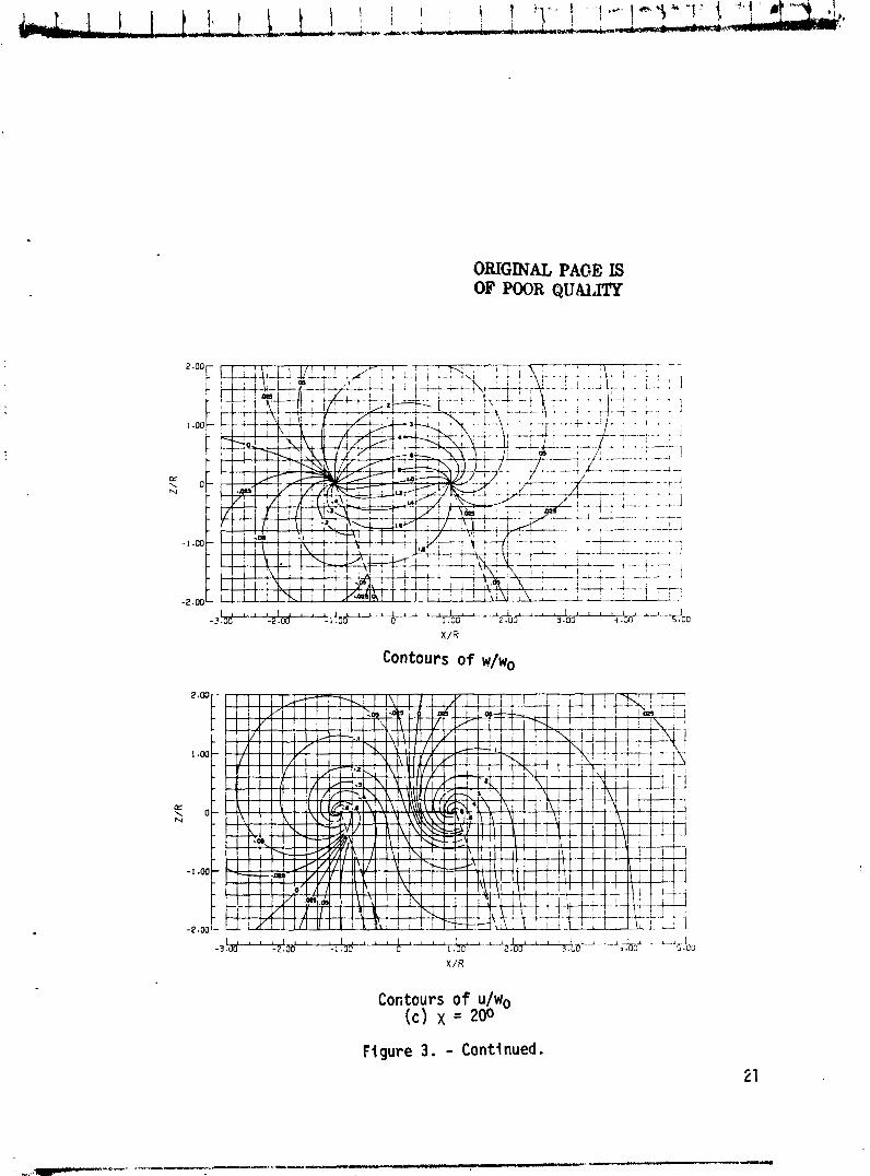
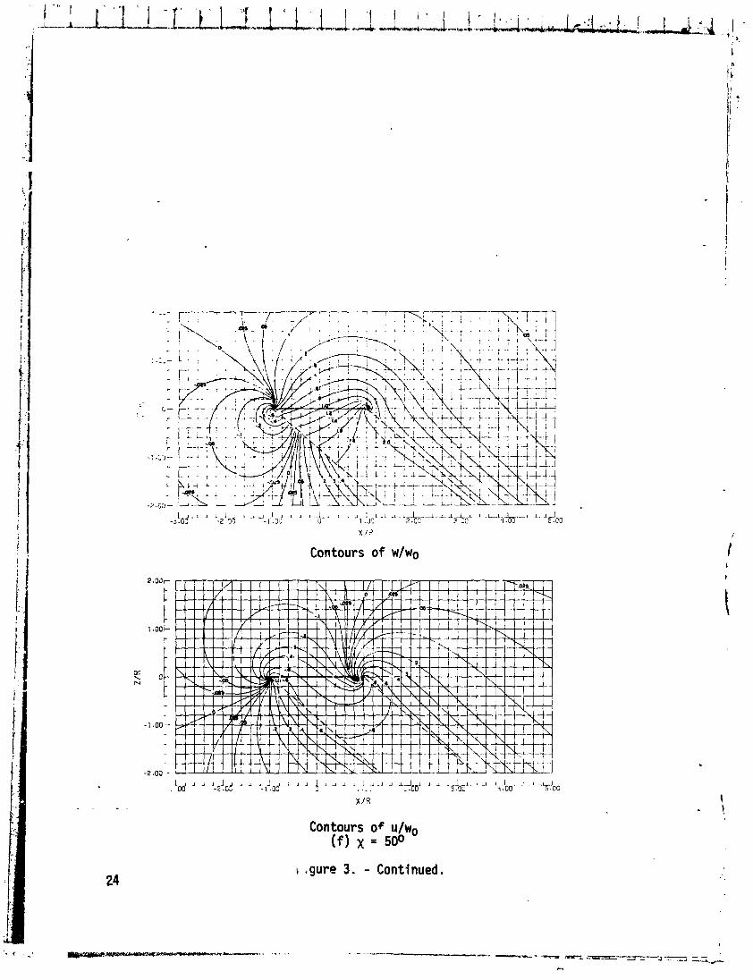
given i n reference 6. A sample se t o f charts (from ref. 7) for both the v e r t i c a l and long i tud ina l induced ve loc i t y r a t i o s i s given i n f i g u r e 3.
The Average Induced Veloc i ty
As noted e a r l i e r , Glauer t 's formulat ion o f the induced . *e loc i ty o f a r o t o r was merely a plaus!5le guess. The simple vor tex theory can be used t o examin: the v a l i d i t y cif the value which he selected. Consider a r o t o r o f b blades. each o f which has a bound c i r c u l a t i o n oC r' over i t s s r l t i r e length. The elemental l i f t 2n the blade i s found from the Kutta-Jouk~wski theorem t o b~
where UT i s the t a n g e ~ t i a l ve1oc.i:~ normal t o the blade ax is and I' i s the bound c i r c ~ i l a t i o n . The t o t a l t h rus t o f the r o t o r i s found by i n teg ra t i ng the elemental t h rus t over the length ( radius) of the blades and then averaging t h i s value araurid the disk; t h a t i s
Subst i tu te equation (15) i n t o equation ( 4 ) t o obta in
and then solve equation (16) f o r r t o y i e l d
Now the number o f "vortex r i ngs " formed per u n i t time a t the r o t o r i s 2 . These are car r ied down the wake w i th the mean ve loc i t y a t the r o t o r
( Q R ~ P ~ + A') . Thus. the v o r t i c i t y along the edge o f the wake i s
Subst i tute equation (17) i n t o equation (18), and s imp l i f y the r e s u l t t o j i e l d
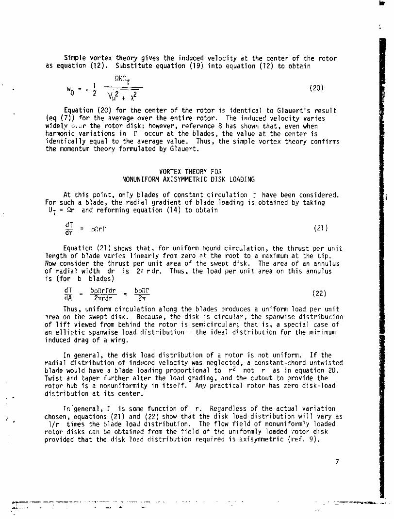
Simple vor tex theory g ives the indirced v e l o c i t y a t the cen te r o f the r c t o r as equat ion ( 1 2 ) . Subs t i t u t e equat ion (19) i n t o equat ion (12) t o ob ta i n
Equation (20) f o r the cen te r of t he r o t o r i s i d e n t i c a l t o G lauer t ' s r e s u l t (eq ( 7 ) ) fo r the average over the e n t i r e r o t o r . The induced v e l o c i t y va r i es w ide ly o . ~ r the r o t o r d i sk ; however, reference 8 has shown t h a t , even when harmonic va r i a t i ons i n I' occur a t the blades, the value a t the cen te r i s i d e n t i c a l l y equal t o the average value. Thus, the simple vo r tex theory conf i rms the momentum theory formulated by Glauert .
VORTEX THEORY FOR NONUNIFORM AXISYMMEThIC DISK LOADING
At t h i s p o i r ~ t , on ly blades of constant c i r c u l a t i o n r have been considered. For such a blade, the r a d i a l g rad ien t o f b lade load icg i s obtained by t ak i ng
U T = Rr and re fo rm i r~g equat ion (14) t o ob ta i n
Equation (21) shows t ha t , f o r un i form bound c i r c i t l a t i o n , the t h r u s t pe r u n i t l eng th o f blade var ies l i n e a r l y from zero at the r o o t t o a maximum a t the t i p . Now consider the t h r u s t per u n i t area o f the swept d isk . The area o f an annulus o f r a d i a l w id th d r i s 2~ r d r . Thus, the load per u n i t area on t h i s annulus i s ( f o r b blades)
Thus, un i form c i r c u l a t i o n along the blades produces a un i fo rm load per u n i t qrea on tne swept d isk . Because, the d isk i s c i r c u l a r , the spanwise d i s t r i b u c i o n o f l i f t viewed from behind the r o t o r i s semic i rcu lar ; t h a t i s , a spec ia l case o f an e l l i p t i c spanwise load d i s t r i b u t i o n - the i dea l d i s t r i b u t i o n f o r the minimum induced drag o f a wing.
I n general, the d isk load d i s t r i b u t i o n o f a r o t o r i s no t uniform. I f the r a d i a l d i s t r i b u t i o n o f indvced v e l o c i t y was neglected, a constant-chord untwis ted blade would have a blade load ing p ropor t iona l t o r* no t r as i n equat ion 20. Twis t and taper fu r the r a l t e r the load grading, and the cu tou t t o prov ide t he r o t o r hub i s a n o n u n i f o r ~ i t y i n i t s e l f . Any p r a c t i c d l r o t o r has zero d isk - load d i s t r i b u t i o n a t i t s center.
!n 'general , r i s some f unc t i on of r. Regardless o f the ac tua l v a r i a t i o n chosen, equations (21) and ( 2 2 ) show t h a t the d i sk load d i s t r i b u t i o n w i l l vary as l/r times the blade load d ~ s t r * i b u t i o n . The f l ow f i e l d o f nonuni formly loaded
r o t o r d isks can be obtained from the f i e l d of the un i fo rm ly loaded ?o to r d i s k provided t h a t the d isk load d i s t r i b u t i o n requ i red i s ax isymnetr ic ( r e f . 9 ) .

Consider the t r i angu la r load d i s t r i b u t i o n o f f i g u r e 4. It can be approximated by a stepwi se d i s t r i b u t i o n o f loads compri sed of one 1 arge posi t i ve load (1.5 t i m s normal s t rength) and a ser ies o f small negative loads of smaller radius. Such a load d i s t r i b u t i o n would be generated by a nest o f coaxial vortex cy l inders such as shown i n f i gu re 5.
The cont r ibu t ion o f each o f these cy l inders t o the f l cw a t ( X / R , Y/R, Z/R) w i l l be propor t ional t I t s vortex strength and can be read from charts such as f igure 3 a t the oo in t P(x/R) (Riffv), ( Y / R ) (R/Rv) , (z/R) (RIR,,)] . The induced ve loc i t y a t t h a t po in t i s the sum o f the contr ibut ions of a l l the cy l inders. A sample ca lcu la t ion f o r a t r i angu la r loading a t (X/R = 0.2, Y / R = 0, Z/R = 0.1) and f o r x = 90° i s shown i n f i g u r e 4.
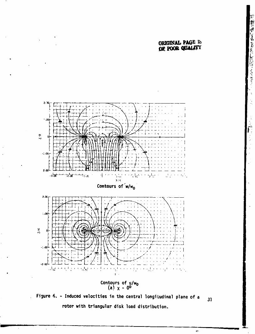
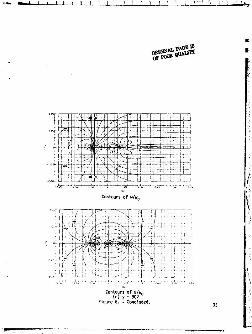
The actual d i s t r i b u t i o n o f load on the d isk has very la rge and s i g n i f i c a n t ef fects on the d i s t r i b u t i o n o f induced ve loc i ty . A few sample charts are pre- sented i n f i gu re 6. A d i r e c t comparison i s presented i n f i gu re 7. Obsevve t h a t t h e w i s a region o f upwash i n f r o n t o f , and encompassing, the leading edge o f the d isk i n each case. The major differences occur over the d isk and acrcss the wake. I n constrast t o the smooth increase i n downwash along the r o t o r ax is i n the uniform case, the t r i angu la r case shows an increase a t f i r s t , then a decrease t o zero a t the r o t o r center, an upwash behind the center, and then, f i n a l l y a rap id increase t o the ti-hi ling edge. The d i s t r i b u t i o n across the wake i t s e l f i s markedly d i f f e r e n t i n 5 t h cases.
One other po in t i s very s ign i f i can t . Under tho present assumptions, the rotor-induced f low i s dependent only upon the skew angle Y . The t o t a l f low f i e l d i s the vec tor ia l sum o f the uniform external f low and the r o t o r induced ve loc i t ies . The t o t a l f i e l d may be markedly d i f f e r e n t dependent upon the r o t o r angle o f at tack and loading. This feature i s i l l u s t r a t e d by f i g u r e 8.
COMPARISON WITtI EXPERIMENT
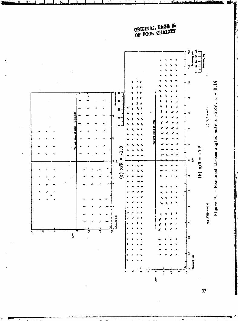
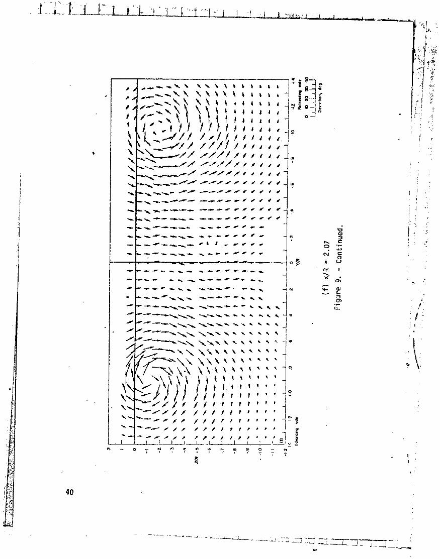
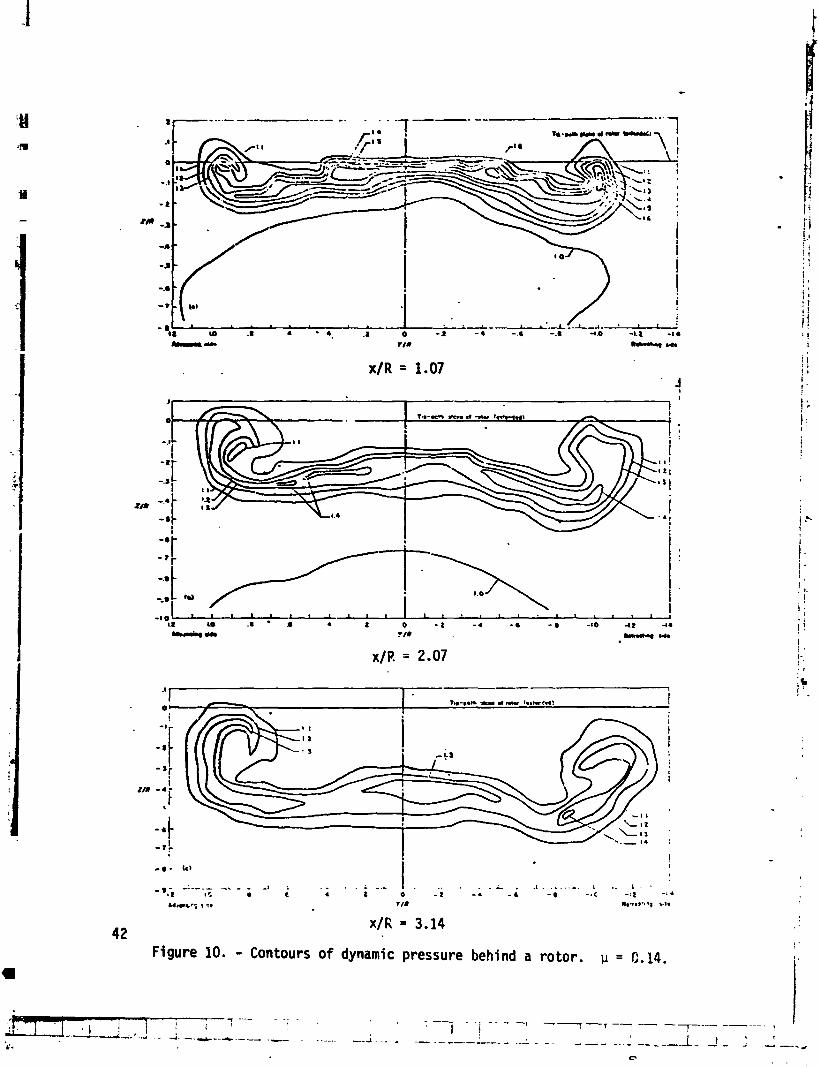
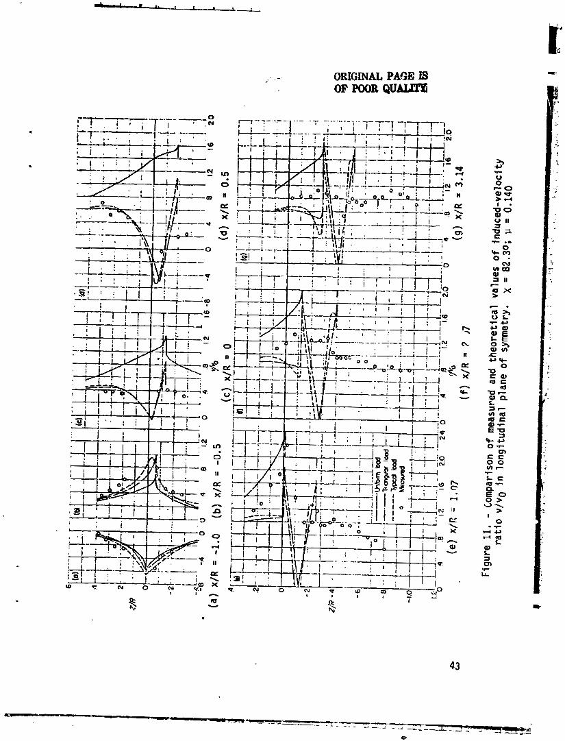
NACA Rep 1319 ( re f . 9) presents the resu l t s o f comprehensive f low surveys near a r o t o r operating i n the wind tunnel. Sample resu l t s are given i n f igures 9 and 10. Cornpariscn o f theory and experiment i n the centra l plane o f the r o t o r i s shown i n f i gu re 11. I t i s evident t ha t the rad ia l d i s t r i b u t i o n O F loading i s s i g n i f i c a n t i n the cor re l2 t ion . On the other hand, an e a r l i e r paper ( r e f . 10) showed tha t the uni fow, load d i s t r i b u t i o n does g ive a reasonably good appsoxi- mation t o the average induced ve loc i t y across a span equal t o the r o t o r diameter.
Another s i g n i f i c a n t feature of f i g u r e li i s the evident f a i l u r e o f the theory i n the region a f t o f the r o t o r . This r e s . ~ l t i s obtained because o f the extremely rap id r o l l up o f the wake v o r t i c i t y beitind the ro to r . Figure 12 shows contours o f equal v o r t i c i t y behind th? r o t o r and i t i s evident t ha t the r o l l up i s already wel l underway a t the t r a i l i n g edge o f the ro tor . I n t h i s region, the wake can be modeled by assuming i t t o be about the same as t h a t behind a wing o f equal span.

Some Appl icat ions o f the Theory
Wind tunnel f low measurements g i ve reasqn t o be l i eve t h a t the major :actors a f f e c t i n g the f l ow f i e l d are i n c l dded i n the t h e o r e t i c a l cons iderat ions desc-i bed above. Thus, the t heo re t i ca l r e s u l t s shoujd be adequate t o exp la i n the induced e f f e c t s found on he l i cop te r s and compound a i r c r a f t ( r e f . 11 ) . Th is sec t ion o f t h i s paper w i l l examine the ex ten t t o which t h i s conc lus ion i s t r ue .
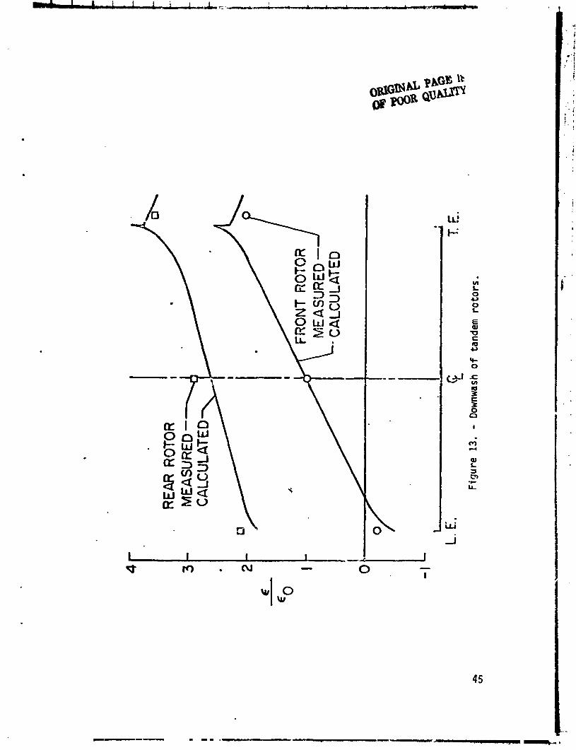
Mu1 t i r o t o r he1 i copters. - The f i r s t example w i 11 be a tandem-rotor system which was tes ted i n ?.he Langley f u l l - s c a l e tunnel ( r e f . 12). B a s i c a l l y the model was s imply two i d e n t i c d l 15-foot-diameter r o t o r s w i t h no v e r t i c a l o f f s e t and a gap o f on ly 6 inches between the r o t o r t i p s . Thrust and torque were measured and, i n add i t i on , f low surveys ( re f . 10) were made a t l o ca t i ons v? ry near t o tne r o t o r . For one l e v e l - f l i g h t cond i t i on , the f l o w measur?tWnts a re shown i n f i g u r e 13. The data po in t s represent th! average induced v e l c c i t y across a span o f one r o t o r diameter. These po in t s i n d i c a t e t h a l the avei-age induced v e l o c i t y thrcdgh the rea r r o t o r was th ree t imes t h a t through the f r o n t r o t o r . This co r resp~nds w i t h the simultaneous power measurements which i ndi - cated t h a t thc r ea r r o t o r requ i red th ree t imes as much induced powef. a- the f r on t r o t o r .
The ca lcu la ted induced v e l o c i t i e s i n t h i s case a re a l so shown on f i gu re 13. These ca lcu la ted curves are very c;s;e t o the measured f l ow data and i n d i c a t e t h a t the r ea r r o t o r should r equ i r e niore than 2.5 times as much induced power as the f r o n t r o t o r . Thus i t appears t h a t the t.heory should be adequate f o r e s t i - mating the e f f e c t o f i n t e r f e rence on the o v e r a l l performance o f m u l t i r o t o r he1 i cop te rs . T h x e are, however, c e r t a i n reserva t ions t o t h i s conclusion which w i l l be d;scussed i n a l a t e r sect ion.
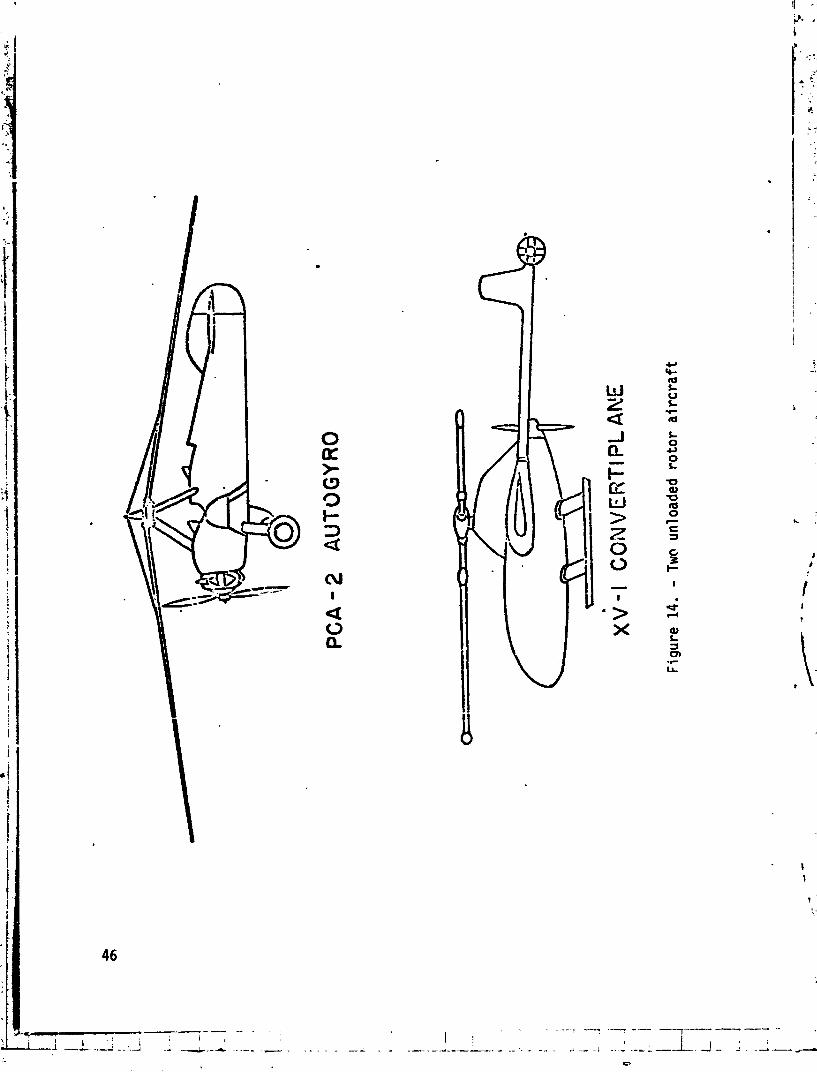
Rotor-wing interference..- Recent attenlpts t o combine the forwzrd- f : ight c a p a b i F t y of an a i rp lane w i t h the v e r t i c a l - f l i q h t capabi 1 i t.j o f a he1 i c o p t e r haire l e d tr! a number. o f unl oaded-rotor conver t ip lane designs, General l y ' speak.ing, these compound a i r c r a f t a re character ized by i.11e presence o f a r o t o r and a wing operat ing i n c lose p rox im i t y t o e :h o ther . Some degree o f niatual i n t e r f e rence i s bound t o be present and i t may have a major e f f e c t upon the o v e r a l l performance o f the a i r c r a f t .
Two such machines are shown i n f i gu re 14. These are the PCA-2 autogyro and tho XV-1 conver t ip lane. If the hover ing a b i l i t y of the XV-1 ; s neglected, the two a i r c r a f t are remarkably s i m i l a r desp i te the passage of son* twen ty - f i ve yzars between t h e i r designs. No power i s app l ied t o the r o t o r i n forward f l i g h t s ince both operate as autogyros i n t h i s f l i g h t regime. An a u x i l i a r y wing i s provided, and t h i s wing ca r r i es a l a rge p o r t i o n o f the l i f t . The p ropu ls i ve fo rce i s obtained i n each case by means o f a p rope l l e r . The major d i f ferences between the two a i r c r a f t 1 i e i n both the absolute and the r e l a t i v e loadings o f the wing and the r o t o r .
The PCA-2 autogyro was tes ted i n f l i g h t . The wing load was determined by measuring thc pressures on the wing surfaces. The re ra inder o f the gross weight 4s supported by the r o t o r . Thus the performance i s r e l a t i v e l y simple t o con~pute s ince the r o t o r l i f t c o e f f i c i e n t and, consequently, i t s mean, o r niomet~tum theory,
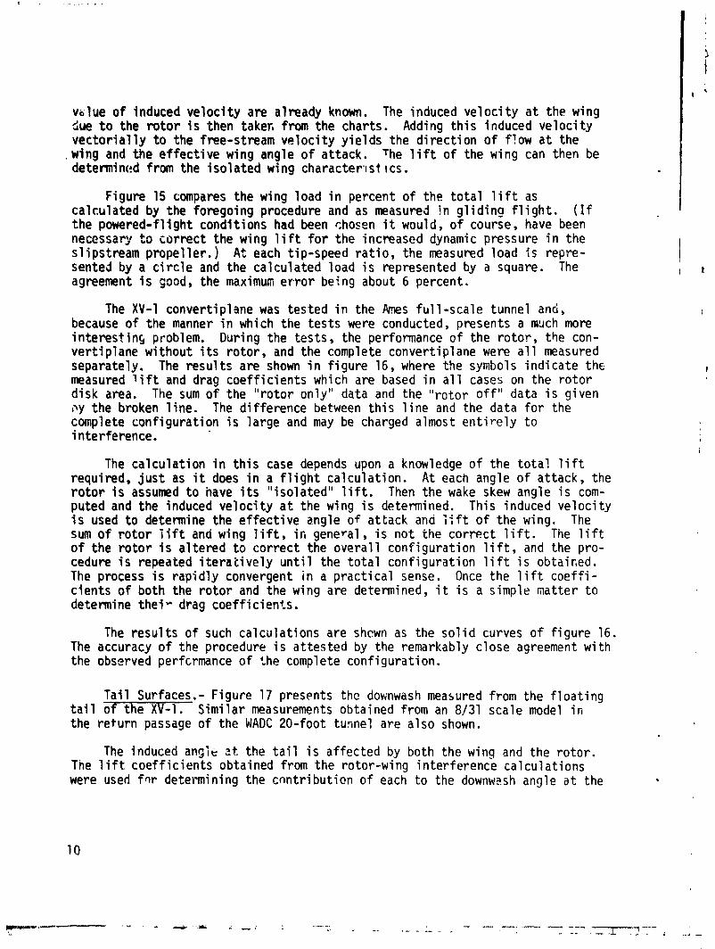
vslue o f induced ve loc i t y are already known. The induced ve loc i t y a t the wing ciue t o the r o t o r i s then taker, from the charts. Adding t h i s induced ve loc i t y v e c t o r i a l l y t o the free-stream ve loc i t y y i e l d s the d i rec t i on o f f!ow a t the
. wing and the effect ive wing angle o f attack. The l i f t o f the wing can then be determi ncfd from the i so la ted wing characten s t I cs .
Figure 15 compares the wing load i n percent o f the t o t a l 1 i ft as calculated by the foregoing procedure and as measured jn g l i d i n g f l i g h t . ( I f the powered-fl i g h t condit ions had been choson i t would, o f course, have been necessary t o cor rec t the wing l i f t f o r the increased dynamic pressure i n the sl ipstream propel ler . ) A t each tip-speed r a t i o , the measured load i s repre- sented by a c i r c l e and the calculated load i s represented by a square. The agreement i s good, the maximum e r r o r being about 6 percent.
The XV-1 convertiplane was tested i n the Clmes fltl l -sca le tunnel and, because of the manner i n which the tes ts were conducted, presents a much more i n te res t i ns problem. During the tests, the performance of the ro to r , the con- ver t ip lane wi thout i t s ro to r , and the complete conver t ip l ane were a1 1 measured separately, The resu l t s are shown i n f i gu re 16, where the symbols ind ica te the measured l i f t and drag coe f f i c i en ts which are based i n a l l cases on the r o t o r d isk area. The sum o f the " ro to r only" data and the " ro to r o f f " data i s given oy the broken l i ne . The d i f ference between t h i s l i n e and the data for the complete conf igurat ion i s large and may be charged almost e n t i r e l y t o interference.
The ca lcu la t ion i n t h i s case depends upon a knowledge of the t o t a l l i f t required, j u s t as i t does i n a f l i g h t ca lcu lat ion. A t each angle o f attack, the r o t o r i s assumed t o nave i t s " iso lated" l i f t . Then the wake skew angle i s com- puted and the induced ve loc i t y a t the wing i s determined. This induced ve loc i t y i s used t o determine the e f f e c t i v e angle of attack and l i ft o f the wing. The sum o f r o t o r l i f t and wing l ift, i n general, i s no t the cor rec t l i ft. The l i f t of the r o t o r i s a1 tered t o cor rec t the overa l l conf igurat ion 1 i ft , and the pro- cedure i s repeated i t e r a t i v e l y u n t i l the t o t a l conf igurat ion l i f t i s obtaiced. The process i s rap id l y convergent i n a p rac t i ca l sense. Once the l i f t c o e f f i - c ients o f both the r o t o r and the wing are determined, i t i s a simple matter t o determine the iu drag coef f i c ien ts .
The resu l t s o f such calculat ions are shcwn as the sol i d curves o f f i gu re 16. The accuracy of the procedure i s at tested by the remarkably close agreement w i th the observed perfcrmance of the complete conf igurat ion.
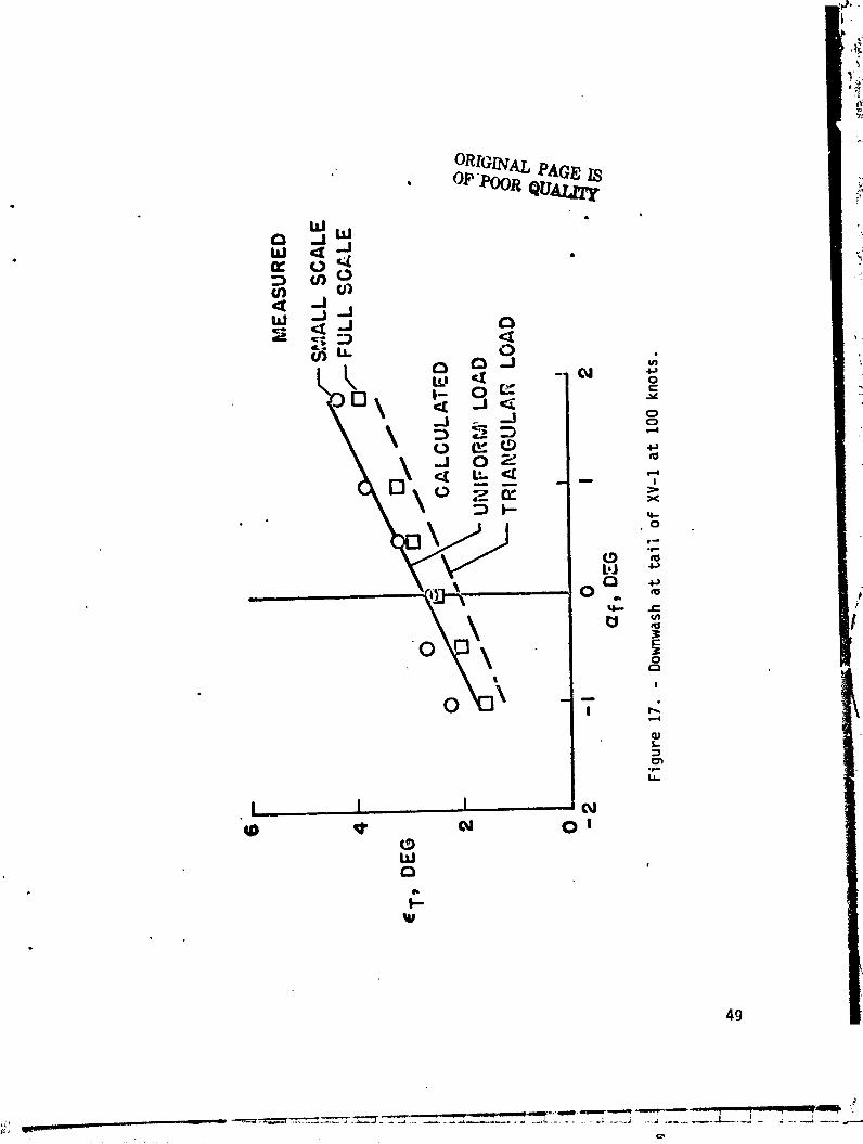
Ta i l Surfaces,- Figure 17 presents thc downwash measured from the f l o a t i n g t a i l o f the X V - I . S imi la r measurements obtained from an 8/31 scale model i n the re turn passage of the WADC 20-foot tunnel are a lso shown.
The induced angle a t the t a i l i s affected by both the wing and the ro tor . The l i ft coe f f i c i en ts obtained from the rotor-wing in ter ference calculat ions were used f ~ r determining the c n n t r i but ion o f each t o the downw?.sh angle a t the
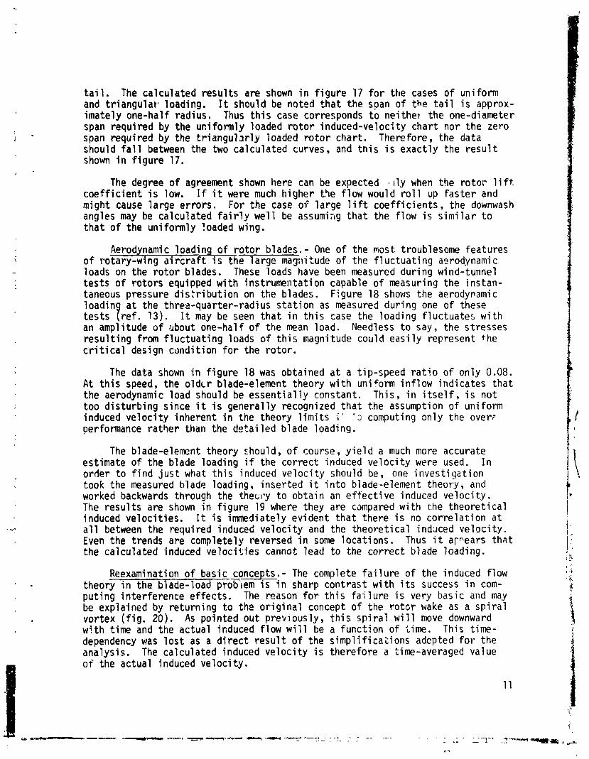
t a i l . The ca lcu la ted r e s u l t s are shown i n f i g u r e 17 f o r the cases o f uniform and t r i a n g u l a r loading. It should be noted t h a t the span of the t a i l i s approx- imate ly one-half radius. Thus t h i s case corresponds t o ne i the) the one-diameter span requi red by the uni formly loaded r o t o r induced-ve loc i ty char t nor the zero span requi red by the t r i a n g u l a r l y loaded r o t o r char t . Therefore, the data should f a l l between the two ca lcu la ted curves, and t n i s i s exac t l y the r e s u l t shown i n f i g u r e 17.
The degree o f agreement shown here can be expected l l y when the rota? l i f t . c o e f f i c i e n t i s low. If i t were much h igher t3e flow would r o l l up f as te r and might cause l a rge e r ro rs . For the case o f la rge l i f t coe f f i c i en t s , the downwash angles may be ca lcu la ted f a i r l y w e l l be assumi:~g t h a t the flow i s s i m i l a r t o t h a t of the un i formly loaded wing.
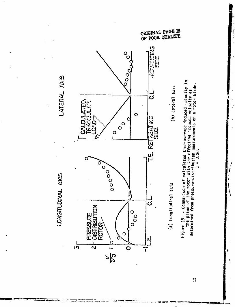
Aerodynamic loadinq o f r o t o r blades. - One o f the most troublesome features o f rotary-wing a i r c r a f t i s t he l a rge mag:litude o f the f l u c t u a t i n g asrod,ynami c loads on the r o t o r blades. These loads have been measured dur ing wind-tunnel t e s t s o f r o t o r s equipped w i t h ins t rumentat ion capable o f measuring the instan- taneous pressure d i s:ri bu t ion on the blades. Figure 18 shows the aerodynami c l oad in a t the three-quarter-radius s t a t i o n as measured dur ing one o f these t e s t s 9 r e f . 13). It may be seen t h a t i n t h i s case the loading f luctuate: w i t h an amplitude o f i ~ b o u t one-hal f o f the mean load. Needless t o say, the stresses r e s u l t i n g from f l u c t u a t i n g loads of t h i s magnitude could e a s i l y represent the c r i t i c a l design condi ' t ion f o r the ro to r .
The data shown i n f i g u r e 18 was obtained a t a t ip-speed r a t i o o f on ly 0.08. A t t h i s speed, the o l d c r blade-element theory w i t h un i form in f low ind ica tes t h a t the aerodynamic load should be e s s e n t i a l l y constant. This, i n i t s e l f , i s n o t too d i s tu rb i ng since i t i s genera l ly recognized t h a t the assumption o f un i form induced v e l o c i t y inherent i n the theory l i m i t s - i ' ' 3 computing on ly the over7 performance ra the r than the de ta i l ed blade loading.
C I
The blade-element theory zhould, o f course, y i e l d a much more accurate est imate o f the blade loading i f the cor rec t induced v e l o c i t y were used. I n
I *
o rder t o f i n d j u s t what t h i s induced v e l o c i t y should be, one i nves t i ga t i on took the measured blade loading, inser ted i t i n t o blade-element theory, and worked backwards through the t h e ~ r y t o ob ta in an e f f e c t i v e induced v e l o c i t y .
I The r e s u l t s are shown i n f i g u r e 19 where they are campared w i t h the t heo re t i ca l induced ve loc i t i es . It i s immediately ev ident t h a t there i s no c o r r e l a t i o n a t
I* !
a1 1 between the requi red induced v e l o c i t y and the t heo re t i ca l induced v e l o c i t y . 1 . Even the trends are completely reversed i n sonle loca t ions . Thus i t ar3ears t h a t the ca lcu la ted induced v e l o c i t i e s cannot lead t o the cor rec t blade loading.
I:, ! 3 t .. I '
Reexamination o f basic concepts.- The complete f a i l u r e o f the induced f iow 8 A q $*,
theory i n the blade-load problem i s i n sharp con t ras t w i t h i t s success i n com- 1 pu t ing in te r fe rence e f f ec t s . The reason f o r t h i s f a i l u r e i s very basic and may i4 be explained by re tu rn ing t o the o r i g i n a l concept o f the r o t c r wake as a s p i r a l vor tex ( f i g . 20). As pointed ou t prev ious ly , t h i s s p i r a l w i l l move downward w i t h t ime and the actua l induced f low w i l l be a f unc t i on o f t ime. This tirne-
3 dependency was l o s t as a d i r e c t r e s u l t o f the s i m p l i f i c a t i o n s adcpted f o r the analysis. The ca lcu la ted induced v e l o c i t y i s there fo re a time-averaged val ue o f the actua l induced ve loc i t y .
11
i * m.eqn---r- .-, C .- -.- - r- .-a*-. -. -.-... - . .. . . . .- . .. . . , . ,. . .
- - '-I-' .f"""UI -* ;, - -. -

Now consider a p o i n t P , f i x e d i n i t s p o s i t i o n w i t h respect t o the r o t o r , as, f o r example, a p o i n t on a f ixed-wing surface. As the s p i r a l va r tex pro- g r e s s ~ ~ downward, the p o i r i i P w i l l "see" a l l o f i t s poss ib le pos i t i ons . Therefore, the mean induced v e l o c i t y a t P should be the time-averaged value ca lcu la ted by theory. Thus, the ca lcu la ted induced v e l o c i t i e s a1 low accurate estimates o f ro to r -w i ng i n t e r f e rence t o be made.
Next consider p o i n t Q which i s on t he r o t o r blade and which ro ta tes w i t h the blade. Since the s p i r a l vor tex s t a r t s a t the blade t i p , t r e r e w i l l , a t any azimuth pos i t i on , be one, and on l y one, p o s i t i o n o f the s p i r a l w i t h respect t o
Q . Thus Q w i l l no t "see" the time-averaged ind~uced v e l o c i t y g i v t n by the theory. Thus, as shown before, the theory cannot be app l ied t o f i n d i n g the induced v e l o c i t i e s needed f o r c a l c u l a t i n g he blade loads. The ac tua l blade load ing problem i s c l o s e l y r e l a t e d t o f l u t c e r i n t h a t the unsteady aerodynamics cannot be neglected.
The more modern r o t o r theor ies take i n t o account the unsteady character o f the f low and, i n add i t i on , t u r n t o mo:*e r e f i n e d models o f the \;3ke. A b r i e f survey o f some o f the more recent developments i n t h i s area wi 11 fo1lol;l.
There i s an i n t c rq~ed ia te problem between the average externa l i n t e r f e rence and th? de ta i i ed S l ~ d c loads. Consider the p o i n t R on a second r o t o r near the f i r s t . Does t h i s p o i n t see a time-averaged v e l o c i t y o r no t? Local ly , 3n the blade, i t probably does not , and the change i n the de ta i l ed blade load ing 2s a r c s u l t o f i n t e r t r ence can probably no t be c z l c ~ l ated w i t h any degree o f accuracy. However, zt ' least f o r the tandem r o t o r s o f NACA TN's 3236 ( re f . 12) and 3242 ( r e f . l o ) , the re i s experimental evidence t o i nd i ca te t h a t the o v e r a l l r o t o r forces can be determined by use o f the present theory. This may no t be the case f o r a l l conf igurat ions. I t i s the re fo re suggested t h a t r n u l t i r o t o r in te r fe rence ca1c1:lat ions based on the present induced-f l-w theory be accepted f o r the ?resent bu t always sub jec t t o the p r o v i s i c n t h a t ,?xperimental v e r i f i - caLion i s requ i red i n each case.
CALCULATION OF BLADE LOADS
The moder:l app l i ca t ions o f r o t a r y wing vor tex theory i n v o ! v ~ the c a l c u l a t i o n o f the detai;s o f the blade load d i s t r i b u t i o n . The d iscuss ion here in wi1 I l t l r g e l y f o l l o w the developments i n the Uni tea Stztes. A1 though complete d e t a i l s do no t appear t o be ava i l ab l e i n t h j s country, M i l ' s textbook ( r e f . 14) makes i t c l e a r tt,?t very s i m i l a r developments have taken place i n the USSR and t h a t those analyses o f t e n predated our own. The present d iscuss ion must a!so deal on ly i n gene ra l i t i e s . Closed form so:utions t o the problem do no t e x i s t . Only the numerical r e s u l t s from s p e c i f i c sample cases run on d i g i t a l computers a re ava i lab le .
The e a r l i e r u iscuss ion hzs shown c l e a r l y t h a t the instantaneous ve loc i t j e s , no t the average v e l b c i t i e s , a t the blade a re requi red. Ir: add i t i on , i t i s ev ident t h a t quas i - s t a t i c so lu t ions can no t be meaningful i n the face o f the wide ly vary ing l o c a l v e l o ~ i t i e s and angles o f a t t ack on the blades. The need f o r an unsteady ana lys is was f u r t h e r shown by the e s s e n t i a l l y simul taneous papers

o f Loewy ( re f . 15) and Timmn and van de Vooren ( re f . 16). Both analysis demonstrated the existence of previously uncalcul ated wake-exci t ed f l u t t e r moties even f o r a hovering rd tor .
The i n i t i a l theore t ica l inves t iga t ion o f blade loads was conducted by P i z i a l i and DuWaldt a t Cornell Aero Labs ( re f . 17). The model used f o r t h e i ~ calculat ions i s shown i n f i ~ u r e 21. The blade i s d iv ided i n t o a number o f rad ia l segments w i th the bound vortex f i x e d on the quar ter chord. The bound c i r cu la t i on along each r a d i a l segment i s constant. Thus, a t each junc t ion of segments a vortex w i l l be shed, and the strength o f t h i s vortex w i ! l be equal t o the difference i n c i r c u l a t i o n o f the two segments. The ra ta t i ona l motioc of the blade i s considered i n terms o f a number of azimuth steps w i th the bound c i r cu la t i on c h a n g i ~ from step t o step. I n order t o s a t i s f y conservation o f v o r t i c i t y , a vortex must be shed from, and p a r a l l e l to, the t r a i l i r t g edge o f the blade a t each step. Furthermore, the strength o f t h i s vortex must be ?qua1 t o the d i f ference i n bound c i r c u l a t i o n between the two azimuth steps d t each r a d i a l s tat ion. This g r i d - l i k e wake i s assumed t o be ca r r i ed uniformly away from the r o t o r t ip-path plane by the forward ve loc i t y and by a uniform a.verage induced veloc i ty . Thus, i t i s constrained t o l i e w i t h i n the c y l i n d r i c a l boundaries of the wake m d e l used e a r l i e r i n the average dowi~wash calculat ions.
A t the s t a r t o f the calculat ions, the bound c i r cu la t i ons on t i le blade are unknown; however, a l l o f the wake vortex strengths may be formed as functicqs o f the unknown bound 'c i rcu la t ions . The blade angles, f lapping angles, and t i le deformations o f the b l a d ~ were preassiqned i n t h i s analysis; thus, the d.ynamic response of the blades was not calculated. Control points were specif ied on the three-quarter chord a t the midpoint o f each segment. It was then possible t o se t 11p an array o f simultaneous equations i n the unknown blade c i rcu la t ions , using the Biot-Savert law t o obta in the induced ve loc i t i es a t the contro l points. These simultaneous equations were then solved by mat r ix invers ion tech- niques on the computer.
Observe the in te r re la t ionsh ips involved i n t : ~ e ;o;ution. Charts of induced ve loc i t i es f o r standavdized load d i s t r i bu t i ons no locger nave any meaning. The only d i s t r i b u t i o n w i th meaning i s the one f o r t ha t p a r t i c u l a r r o t o r a t t h a t pa r t i cu la r f l i g h t condi t i cn .
The resu l t s from the n?w technin,?ro xere f a r superior t o the o l d urliform-dawnwash, quas:-st.atiz theory i n many respects; however, as pointed out by the authors, there were a',so numerous problems. One major problem was tha t the calculated f i rst-hdrmonic f lapping mome:lt wa; not zero, even when measured blade motions and deformation:; were input LO the program. I t was fu r the r recognized tha t the s ingie t h r ee-quarter-chord cont ro l po in t was probably too crude, and tha t wake decormatims n~ igh t have t o be considered as wel l .
Certain of these improvements were incorporated by P i z i a l i i n a l a t e r paper (ref. 18). I n t h i s version o f ;:he m a l y s i s , the blade was represented as a continuous d i s t r i b d t i o n o f v o r t i c i t y by means o f a Glauert ser ies an^' :he span- wise v o r t i c i t y behind the t r a i l i n g edge was "e f fec t i ve l y f i t t e d " w i t b a con- tinuous sheet ( re f . 19) i n the region imnediately behind the blade ( f i g . 22). The e n t i r e ca lcu la t ion was set up i n a loop such tha t the a i r loads were computed and then the resul t i ~ g Sapping arid blade bending were computed. These resu l t s

were compared w i t h the same quant i t ies from the previous i t e r a t i o n and the e n t i r e procedure was repeated u n t i 1 the a i r loads, f lapping, and dynamic response a l l converged. A sample se t o f resu l t s i s compared w i t h f l i g h t measurements i n Tiyun? 23. Considering the complexity of the ca l cu la t i on and the simp1 i f y i n g assumptions, the resu l t s were qu i te encouraging.
P i z i a l i ' s discussion pointed t o the f a c t t ha t many of the remaining discrepancies between theory and experiment could be qual i t a t i v e l y accounted f o r by phys ica l l y reasonable d i s to r t i ons of the wake from the simple he1 i c a l sheets which he was s t i l l using. Actual ly, C r i m i , a lso a t Cornell Aero Lab, was already working on the problein.
Crimi ' s o r i g i n a l analysis ( re f . 20) was d i rec ted a t the external f i e l d o f the ro to r , and, f o r t h i s purpose, he represented the wake by a s ino le t i p vortex from each blade. No spanwise v o r t i c i ty was used despite the assumption tha t the t i p v o r t i c i e s had a strength containina a s ine 9 component. 2 i g i d hel ices were assumed a t the s t a r t o f the calculat ion, and numerous contro l points were chosen along the hel ices. Then the induced ve loc i t i es a t the contro l po in ts were calculated. (Certain i n f i n i tes i n the calcu?at ion were avoided by the assumption of f i n i t e vortex cores.) The vor t i ces were then allowed t o convect t o a new pos i t i on w i th these ve loc i t i es over a time per iod equal t o one step i n blade azimuth pos i t ion . The process was repeated w i t h the new posi t ions u n t i 1 f u r the r changes i n the waie posi t ions were i ns ign i f i cant. The f i n a l wake pos i t i on could then be used to ca lcu la te the f low throughout the f i e l d .
The wake resu l t i nq from t h i s ca lcu la t ion i s shown i n f igure 24. It obviously dupl icates , a t leas t qual i t a t i v e l y , the wake d i s to r t i ons which were found e a r l i e r i n the wind-tunnel f low measurements. A comparison o f the time- averaged nleasured and calculated f low f i e l d s i s shown i n f igure 25. Considering t h a t Crirni 's assumptions omit the e f f e c t o f r a d i a l disk- load d i s t r i b u t i o n , the agreement i s very encouraging.
More recent ly, Sadler (refs. 20, 22) has incorporated s i m i l a r wake d i s to r t i ons i n t o the ca lcu la t ion of blade loads using a f u l l vortex-mesh and working w i th the unsteady aerodynamic problem. The so lu t i on i s ? ided by a " ro tor s tar t -up" approach; t h a t i s , the theore t ica l r o t o r comnences from a dead s t a r t i n whish there i s no wake a t a l l . I n the f i r s t time increment a short wake i s shed, approximate blade loads are calculated, and the shor t wake i s relocated. The process i s repeated by steps i n aximuth u n t i l the complete wake i s generated. Samples o f the resu l t s are presented i n f igures 26 t o 31. Once more the r ~ s u l t s are encouraging.
It would be premature t o c la im tha t the problem of ca l cu la t i ng blade loads i s solved. The comparisons between theory and experiment s t i 11 ind ica te uncomfortably large di f ferences. On the other hand, i t i s evident t ha t many o f I the necessary elements t o a so'lution have been determined and the basic problems I
dea; t w i t h t o some extent. It i s c lear t ha t fa r more det 'lil i s required than , has been employed t o date. Unfortunately, t h i s d e t a i l i s very expensive i n terms o f computcr storage requirements, running time, and cost.

CONCLUDING REMARKS
The development o f r o t a r y wing induced-veloci ty theory bas been traced from i t s o r i g i n as a momentum-theory estimate o f average interference, through simple vortex theory, t o i t s present s tatus where i t i s ind ispensib le i n ca lcu la t ing blade loads. Appl icat ions t o a v a r i e t y o f in te r fe rence problems has been demonstrated. Wherever possible, experimental resu l t s have been presentei t o conf irm the theory.
REFERENCES
1. Glauert, H. : A General Theory o f the Autogyro. R&M No. Ill? , B r i t i s h A.R.C., 1926.
2. Coleman, Robert P.; Feingold, Arnold M. ; and Stempin, Carl . W. : Evaluat ion o f the Induced-Veloci t y F i e l d o f an Idea l i zed He1 ipcopter Rotor. NACA WR L-126, 1945- (Formerly NACA ARR L5E10. )
3. Castles, Walter Jr.; and De Leeuw, Jacob Henri: The Normal Component o f Induced Veloc i ty i n the V i c i n i t y of a L i f t i n g Rotor and Some Examples o f I t s Appl icat ion. NACA Rep. 1184, 1954. (Supercedes NACA TN 2912. ) .
4. Mangler, K. W.; and Squire, H. 8. : The 1;iduced Veloc i ty F i e l d o f a Rotor R&M No. 2642, B r i t i s h A.R.C., 1950.
5. Heyson, Harry H. : Equations f o r the Induced V e l o c ~ t i e s Near a L i f t i n g Rotor w i th Nonuniform Azimuthwise V o r t i c i t y D i s t r i bu t i on . NASA TN 0-394, 1960.
6. Jewel, Joseph W., Jr.; and Heison, Harry H.: Charts o f the Induced Ve loc i t ies Near a L i f t i n g Rotor. NASA Memo 4-15-59L, 1959.
7. Heyson, Harry H. : Theoret ical and Experime . t a l Inves t iga t ion o f the Performance o f a Fan-In-Wing VTOL Configu, a t ion . NASA TN 0-7498, 1973.
8. Heyson, Harry H. : A Note on the Mean Value o f Induced Veloc i ty f o r s He1 i cop te r Rotor. NASA TN D-240, 1960.
9. Heyson, Harry H.; and Katzoff , S.: Induced Ve loc i t ies Near a L i f t i n g Rotor w i t h Nonuniform Disk Loading. NASA Rep. 131 9, 1957. (Supersedes NACA TN 3690 by Heyson and Katzof f and NACA TN 3691 by Heyson.).
10. Heyson, Harry H. : Prel iminary Resul t s from Flow-Fi e l d Measurements Around Single and Tandem Rotors i n the Langley F u l l -Scale Tunnel . NACA TN 3242, 1954.
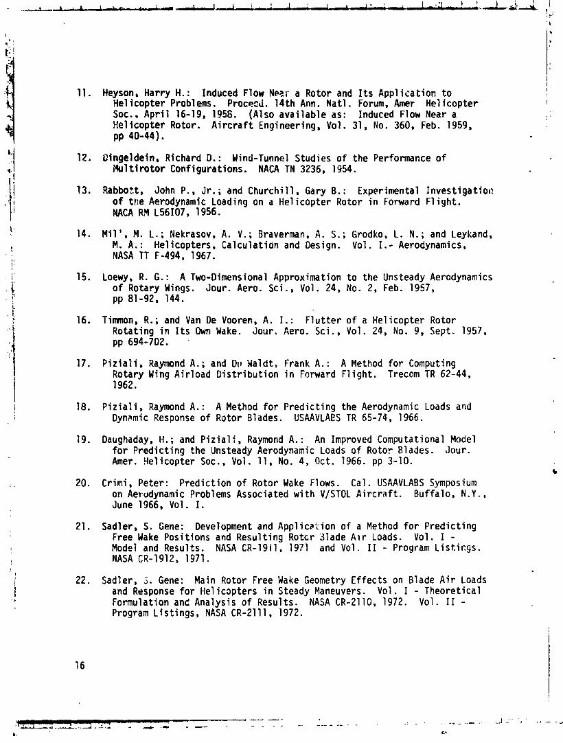
11. Heyson, Harry H. : Induced Flow Nez,;- a Rotor and I t s Appl i s a t i o n t o He1 i cop te r Problems. Proceed. 14 th Ann. Na t l . Forum, Amer He1 i c o p t e r Soc.. A p r i l 16-19, 1958. (Also ava i l ab le as: Induced Flow Near a He l i cop te r Rotor. A i r c r a f t Engineering, Vol. 31, No. 360, Feb. 1959, pp 40-44).
12. Qingeldein, Richard D. : Wind-Tunnel Studies o f the Performance of 1Hu1 t i rotor Configurations. NACA TN 3236, 1954.
13. Rabbott, John P., J r . ; and Church i l l , Gary B. : Experimental Inves t iga t io t? o f the Aerodynamic Loading on a He1 i c o p t e r Rotor i n Forward F l i g h t . NACA RM L56107, 1956.
14. M i l ' , M. L. ; Nekrasov, A. V. ; Braverman, A. S. ; Grodko, L. N. ; and Leykand, M. A. : He1 icopters , Ca lcu la t ion and Design. Vol . I. - Aerodynamics, NASA TT F-494, 1967.
15. Loewy, R. G . : A Two-Dimensional Approximation t o the Unsteady Aerodynamics o f Rotary Wings. Jour. Aero. Sci., Vol . 24, No. 2, Feb. 1957, pp 81-92, 144.
16. Timnon, R.; and Van De Vooren, A. I. : F l u t t e r o f a He1 i c o p t e r Rotor Rotat ing i n I t s Own Wake. Jour. Aero. Sci., Vol. 24, No. 9, Sept. 1957, pp 694-702. .
17. P i z i a l i . Raymond A.; and Du Waldt, Frank A.: A Method f o r Computing Rotary Wing A i r l oad D i s t r i b u t i o n i n Forward F l i g h t . Trecam TR 62-44, 1962.
18. P i z i a l i , Raymond A.: A Method f o r P red i c t i ng the Aerodynamic Loads and Dynamic Response o f Rotor Blades. USAAVLAES TR 65-74, 1966.
19. Daughaday, H. ; and P i z i a l is Raymond A. : An Improved Computational Model f o r P red i c t i ng the Unsteady Aerodynamic Loads o f Rotor Blades. Jour. Amer. Hel icopter Soc., Vol. 11, No. 4, Oct. 1966. pp 3-10.
20. Crimi , Peter: P red ic t ion o f Rotor Wake Flows. Cal . USAAVLABS Symposium on Aerodynamic Problems Associated w i t h V/STOL A i r c r a f t . Bu f fa lo , N.Y., June 1966, Vol. I.
21. Sadler, S. Gene: Development and App l i ca t ion o f a Method f o r P red i c t i ng Free Wake Posi t ions and Resul t ing Rotcr 3lade A i r Loads. Vol. I - Model and Results. NASA CR-1911, 1971 and Vol. I 1 - Program L i s t i c g s . NASA CR-1912, 1971.
22. Sadler, 3. Gene: Main Rotor Free Wake Geometry E f f ec t s on Blade A i r Loads and Response f o r He1 i cap te rs i n Steady Maneuvers. Vol . I - Theoret ica l Formulation and Analysis o f Results. NASA CR-2110, 1972. Vol. I 1 - Program L is t ings , NASA CR-2111, 1972.

Contours o f w/wo
Contours o f u/w0 ( a ) x = 00
F igure 3. - Induced v e l o c i t i e s i n the cent ra l long i tud ina l p lane o f a r o t o r w i t h uniform d isk loading. 19

Contours o f w/wo
Contours o f u/wo (b) x = lo0
Figure 3. - Continued.
ORIGINAL PAGE IS OF POOR QUA1,lTY
Contours o f w/wo
Contours o f u/wo (c) x = 200
FIgure 3. - Continued.

- 3 ! E O o ~ 0 ~ A - u - ~ e ~ L~&~J-J-L -2 J 4.02 A 2 -1 A L 5 J .S3
X / R
Contours of w/wo
Contours o f u/w, (d) x = 300
Figure 3. - Continued.

ORIGINAL PAGY IS OF POOR QUALITY
Contours o f w/wo
Contours o f u/wo (e) x = 400
r igure 3. - Continued.
Contours of w/wo
Contours of u/wo (f) x = 50°
r ,gure 3. - Continued. 24

O~GINAL PAGE 18 OF POOR O U ~
Contours o f w/wO
Contours o f u/wo (91 X = 60°
Figure 3. - Continued.

-3!od- t 1 .I ,J,T!-~ L-J-J. I 1 > i 1 .L A.A i i & o ~ ~ ~ - ~ J , - . L 2 4 L -L -1 - A ~ , ~ ~ L - 1 L - L - ~ - I .OC 3 -. 3. ..; 5 .on
X / R
Contours o f w/wo
C [ I '
2 O t 1
Contours o f u/w, (h )4X = 709
Figure 3. - Continued.
ORIGINAL PAGE Is OF POOR Q U ~
Contours of w/wo
Contours of u/wO ( i l X = 800
Figurt . - Continued.
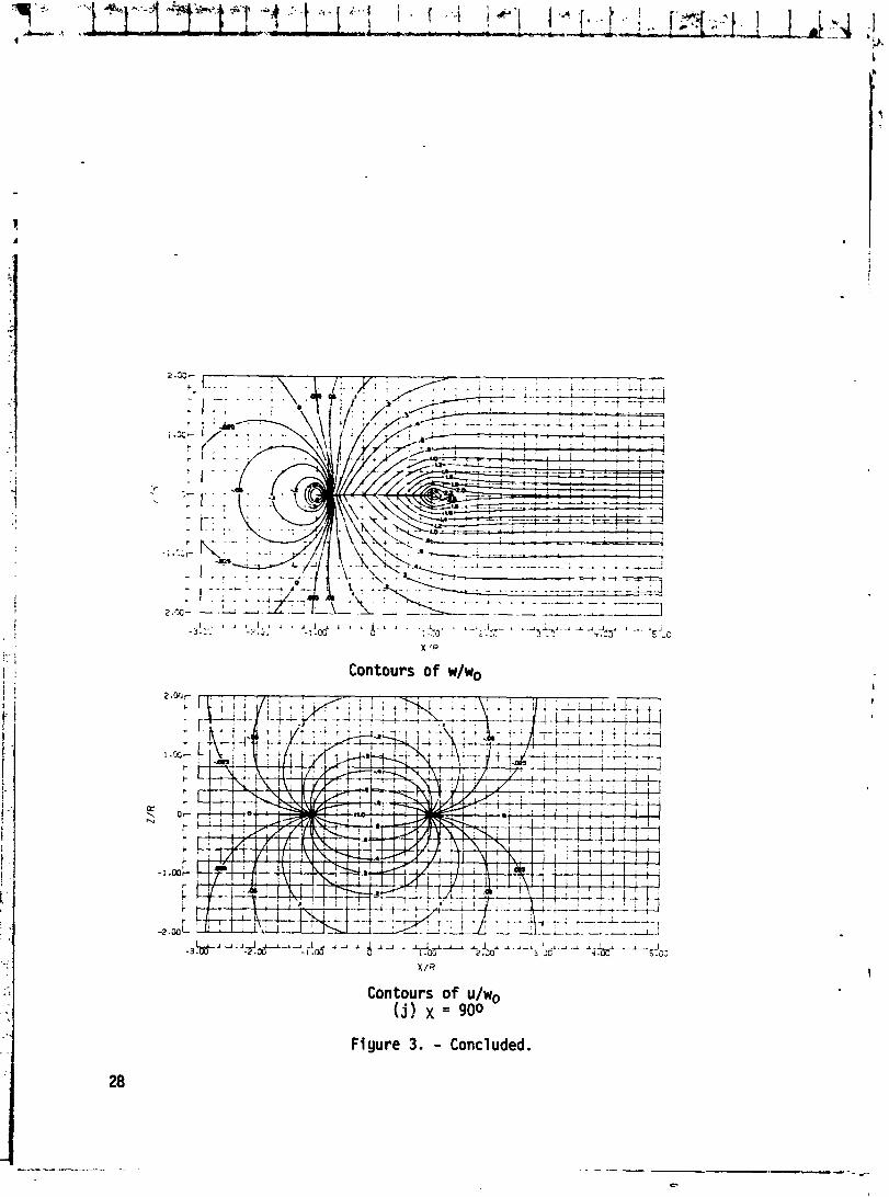
Contours of w/wo
Contours of u/wo (j) x = 900
Fiyure 3. - Concluded.

,.I,. , = - . v -(r;iqar; , = 0. (:!I4 I.. . -. .-- L-- = -1:;- -. - ' L - z . i - . Y L - Z - . ==---i-- -- --- -iC= : -- .. - -. . - Figure 4. - Triangular disk load distribution.

t L . - - . (b) onu uniform axially syrnetric load.
Figure 5. - Assumed vortex pattern of rotor wake.
. . . . . . . . ,
. . . . . .
, -- i-- . - - . .
. . . . . . . ' 1 . . . . . . . . . . . . . . . . . . . . . . . .
. . . . . . . - ----.. . . . . . . . . .
. -3~ - '" - ' -2 f~ -""~- . .A ' - 8 ' ' . I : ' --..I... t ' .&. . -. .,Y, . ..L' c ill I a . 4 ,:'. :. -
x ;;<
Contours of ?w/w0
Contours of u/wo (a! x - 00
Figure 4. - Induced velocities in the central longitudinal plane of a 31
rotor with triangular disk load distribution.
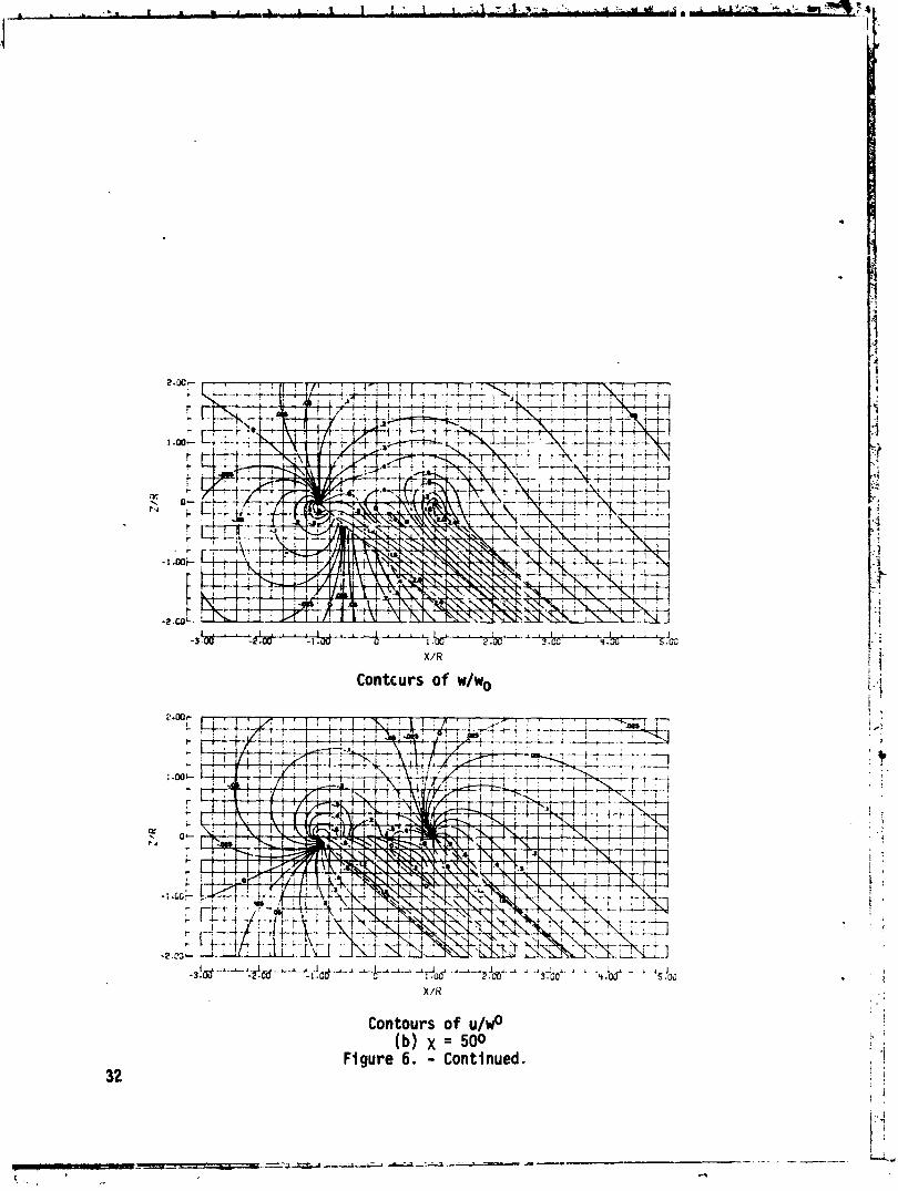
Contcurs o f w/wo
Contours o f u/wo (b) x = 500
Figure 6. - Continued.
. A 2 ? & ~ d . , - A .A ~ ~ L ~ L , -3 .r -I .CC L .*- -L 5 . L 2 . u -
*oy-'*.l&.dd L3&+LA..L 2 . L .A* J,.
X:R
Contours of w/w0
-& I I 2 : ' 'I.!oo' 1 2 4 A . g L 8 ii!cdh L A J7;'Cr,~ . L A 3 .UJ 1 4 J 8 i $1 . I d,: B 4 I , < I , . I . ~ ,
X/K
Contours of 9/w0 ( c ) x = 900
Figure 6 . - Concluded.

(b) Triacgular disk loadillg
Figure 7. - Comparison of induced velocity ratios for uniform an^ triangular disk load distribution. x = 760.

(a)
Uni
form
dis
k l
oa
dil
~g
.
Fig
ure
8.
-. Fl
on.
fie
ld a
t d
iffe
ren
t an
gles
of
att
ac
k r
, h
a s
ing
le
wak
e sk
ew a
ng
le o
f 50
0.

t- I. .P I 1 1% i " J . .f . ' . -- l 7 Y ? r~ . , i f i . *.


m I= an-

ORIGINAL PAGE IS , OF POOR QUALlTfi
I
I
, I '
I ,! ' 2 1
' ' I I
. . I
!
Figure 10. - Contours of dynamic pressure behind a ro tor . p = C.14.
ORIGINAL PAGE IS OF POOR QUBIJTYi

(a) x/R 1.07 (b) x/R = 2.07 (c) x/R = 3.14
Figure 12. - Oistribution o f vor t i c i ty behing rotor . x = 32.30; p = 0.140

ORIGINAL PAGE IS OF POOR QU-

a D
EG
f 9
SUM
OF
GO
FvlP
ON
ENTS
CALC
ULAT
ED
.
A!BN
E
a. D
EG
f 2 (a
) L
ift
co
eff
icie
nt
(b)
drz
g c
oe
ffic
ien
t
Fig
ure
16.
-
Per
form
ance
of
XV
-1
at
100
kno
ts.
, _ .
_.--
_ _ .
_
. _. _
- - -
- --
---.
.-
.-----
---
--I---
- -
9.
----.I-----
--p
-+--
?,.
_r
-. ,.
---
. --
----ri
ri- ; . ;.-x -
. . -
. .
- .- .
. --
-* ---
..-
---.. - --.. -. -
,. .. .
. ,
, ,*.
. -
-7.-
--
-- - '
--- -.
yL
--L
- .-
--a- -i.-i-u-.
I-... d
,-..,
Am
.-
,
: :
-
; ,
. ,<"-
. -
,,
,,
;,
a??'-
---.,.
. .
. .
.
- .,
,. ,
. .
". .
. -
.'
,,,
>,- .
- PG.
.. "* ;
..1.:5
- .,
. ,.-

ORIGIN& PAGE 18 OF POOR QUAI^
a*; i I W J ) aJ0a E aJ aJ ';;z E d
aJ E m u 0 . UJ W v - 0 W X t ' a t ' 3 II - n 3C-I- ZL O W L F -r w ;zul
.r- L O
y.0 1 O W Q)
0 L E % J 0 ul ul aJ ul 't-Z Q) L t ' L rcI a nlc E O E 0 0 UaJL c'+-
l o 7 u
* n w m C v-l aJ'r
aJ5 E L W 3 t' 0 , w
-0 2.
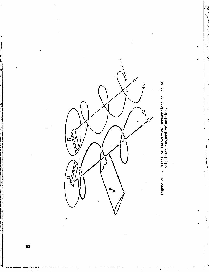
Figure 20. -
Effe
ct o
f th
eore
tica
l as
sump
tion
s on
use
of
cal cul a
ted
indu
ced
velo
citi
es.

ORIGINAL PAGE 4 OF POOR QU-
- - - SfOEWFltEO TJAt Lt NO VORTICES ........ SEPUlElTED SHE0 VORl l C t S
Figure 21. - Vortex wake used by Piziali and Duwaldt in reference 17.
CON1 IWUOUB PART OF WAKE
I I I I I ( A l U F O l l POSITION NOS.) 1
I
X- 1 1-3 . N-5
(WARE SEWE~T NOS.) 3 .
U C
AIRFOIL D l SCRETE SEED g . / * t f 'i VORTlCES
Figure 22. - Blade representation used in reference 18 by Daughaday and Pi rial i .

Figure 23. - Measured and computed lifts from Pinali's analysis. HU-1A at p - 0.08.
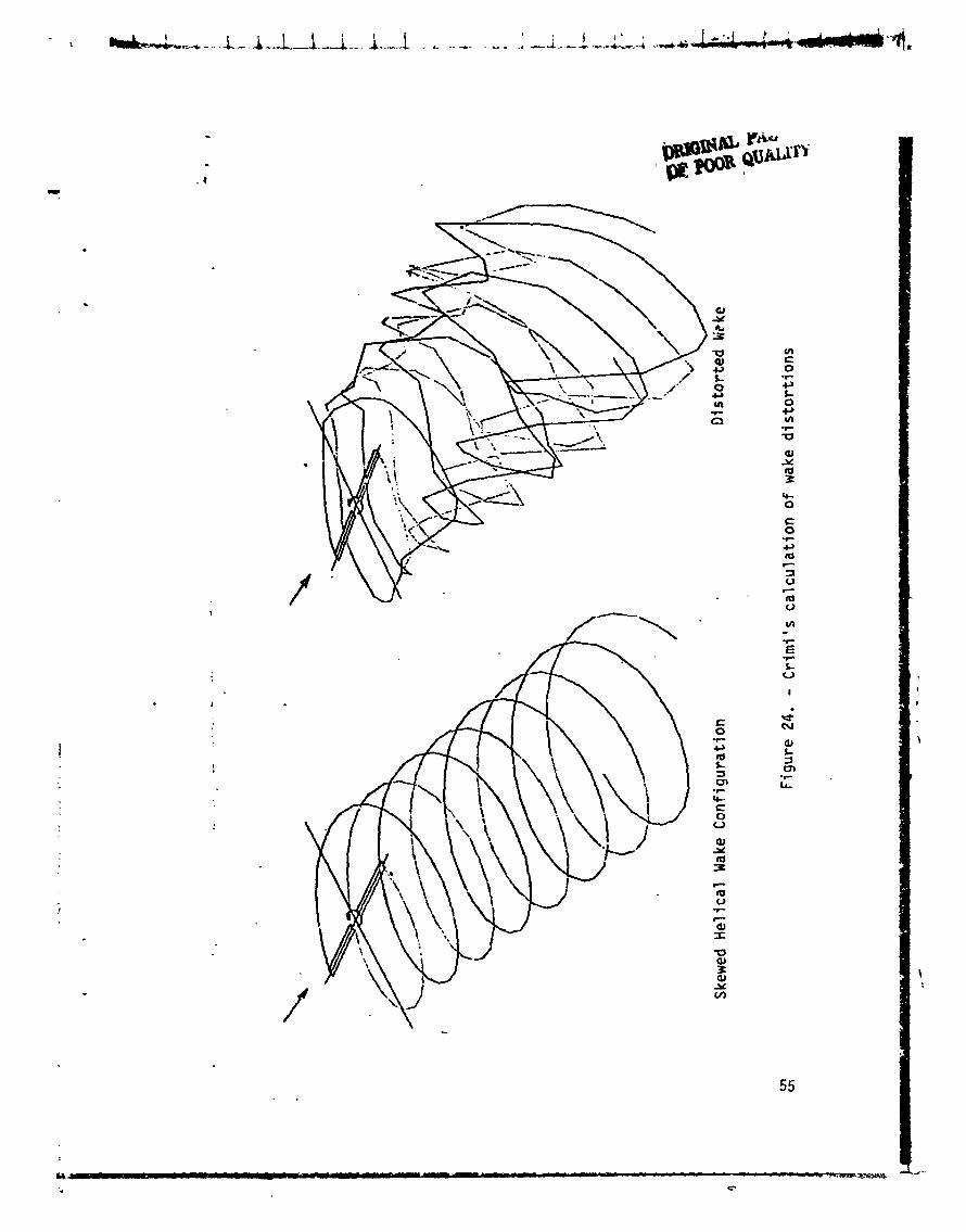

Figure 25. - Cmpari sun of covputed and measured induced downwash below the rotor plane, 0.14, C = 0.00371,
x = 0.5.

Figure 26. - Comparison of computed and measured induced below the rotor plane, p = 0.14. C = 0.00371,.x =0.

bound VOI)eu
Figure 27. - Wake model with combination o f " f u l l mesh" wake and "modified" wake o f t r a i l i n g vcrt4ces only.

I I I I I
m = 0 -
-
- - c o r n p u t e d . . ~ ~ ~ ~ WAKE, RASA -2 - - computed, tip vortex omiy -
P measwed,NACA DATA,NACA TR 1313 I I I I I I L
-1.0 -05 0 0.5 1 .O Y
Figure 28. - Comparison of computed and measured induced below the r o t o r plane, P = 0.14, C = O 0037!, x = 0.
5 9
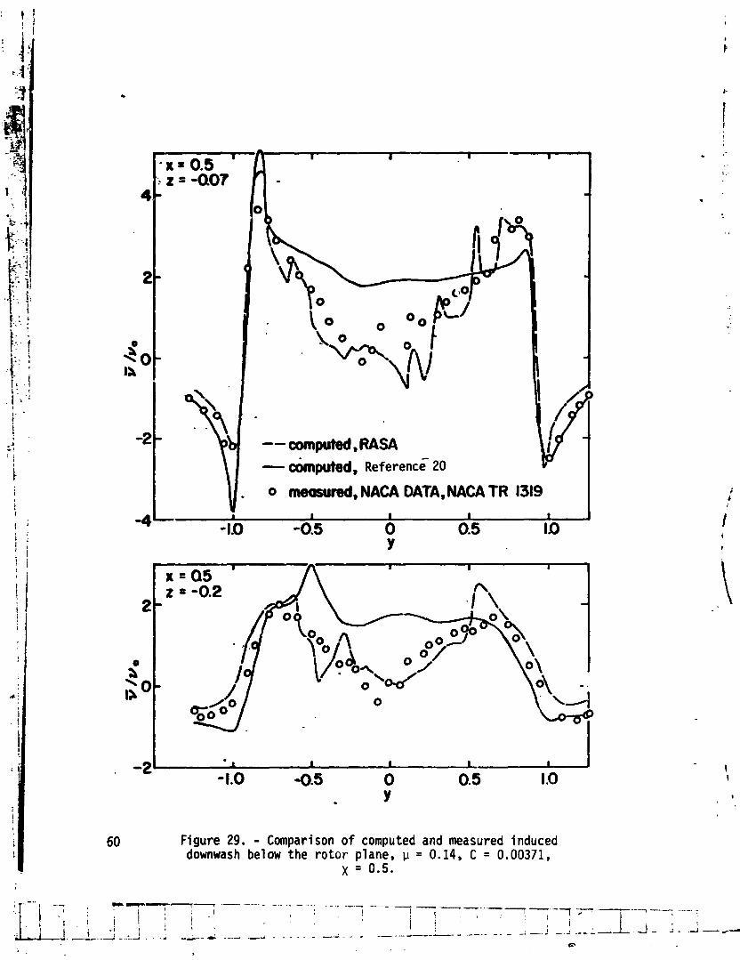
60 Figure 29. - Comparison of computed and measured induced downwash below the rotor plane, p = 0.14, C = 0.00371,
x = 0.5.

OmINAIl PAGE Lg OF W O R - Q U m
Figure 30. - Comparison of computed and measured induced 6 1 downwash below the rctor plane, p = 0.14, C = 0.00371,
x = 0.5.

Bladc No. advancing retreating side side
(a) plan view
maneuver a \ path
-2k (b) side view
Figure.31. - Sadler's calculated wake shape for H-34 at p = 0.225 and 1.34 g.

( a ) p lan view
21
-41 ( b ) s ide view
( c ) r e a r view
Figure 32. - Single two-bladed r o t o r ' s t i p vortex loca t ions , 63 = 0.141 a s = -5.10.

measured, r = .85 , , calculated, r = .8368
0 . 90 180 270 360 3
Figure 53. - Blade airloads for H-34 helicopter, 1 b/ft versus azimuth, p = 0.2
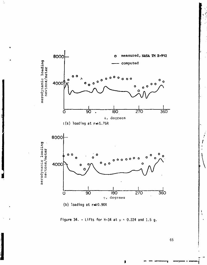
8000 o measured, NASA rn X-952
I - computed
~ b , degrees
l ('a) loading at reG.?SR
0 90 180 270 360 1 1 1 , degrees
( b ) loading at rrc0.90R
Figure 34. - Lifts for H-34 at p = 0.224 and 1.5 g.

I - - - -
7 Author ; r )
*
Harry H. Heyson 9 Performing Orqanization Name and Address
1. Reprt No.
NASA TM 78741
NASA Langley Research Center Hampton, V i r g i n i a 23665
2. Govmment Accation No. 3. Rec~pimt's Catalog No.
12 Sponror~ng Agency Name and Address
Nat ional Aeronautics and Space Admini s t r a t i o n Washington, DC 20546
A BRIEF SURVEY OF ROTARY WING INDUCED-VELOCITY THEORY
8 Perform~nq Or~n lza t~on Report No. I
5. Repon Date
June 1978 ' 6. Performlng Organlzatlon code
10. Work Un~t No. --I 51 6-50-23-01
11 Contract or Grant No I ! 13. Type of Report and Per~od Covered
Technical Memorandum 1 14 Sponsor~ng Agency Code I
1 t 5 Supplementary Notes I
Co l l a te ra l re lease o f notes prepared f o r l ec tu res i n seminar on Aerodynamics o f and Hel icopters, the Pennsylvania State Un ivers i t y , Un i ve rs i t y Park
J u l y 31 -August 4, 1978
The development o f r o t a r y wing induced-ve loc i ty theory i s t rhced from i t s o r i g i n as a momentum-theory est imate of average in te r fe rence , through siniple vor tex theory, t o i t s ' present s ta tus where i t i s ind ispens ib le i n c a l c u l a t i n g blade loads. Appl i ca t i ons t o a v a r i e t y o f in te r fe rence problems i s demonstrated. Wherever possible, experimental r e s u l t s are presented t o conf i rm the t heo r j .
- 1 7 Key Words ~Suggestcd bv Author(s1 l 18. O~ft r~but~on Statement
Induced Ve loc i t i es He1 i copters Autogyros Rotor Blade loads Vortex theory
Unc lass i f ied - Unl i m i t ed
Subject Category 02
For sale by the Natronal Technical lnlormat~on Serv~ce. Spr ~ n e f ~ e l d Vlrg~nla 22161
I
19 k c r ~ t y CIass~f (of thls report1
Unc lass i f ied 22. R~ce'
$4.50 20. Sc;:ar~ty CIasslf (of this papel
Unc lass i f ied 21 No. of Pages
6 5