nasa technical memorandum 100551 stress analysis method ... · pdf file'- r: nasa...
TRANSCRIPT

'- r:
NASA TECHNICAL MEMORANDUM 100551
STRESS ANALYSIS METHOD FOR CLEARANCE-FIT JOINTS WITH BEARING-BYPASS LOADS
Rm A. Naik and J. H. Crews, Jr.
(bASi-!Ztl-100551) SIRESS ANALISIS 1ETEIOD FOB ~ a 9 - 1 7 6 2 ~ CLEABAOCE-PIP JCfb'IS L l ' X H EEIHILG-BYPASS L C A D S (NASA) 32 F CSCL 1 1 D
Unc las G3/24 0191254
JANUARY 1989
National Aeronautics and Space Administration
Langley Research Center Hampton, Virginia 23665-5225
https://ntrs.nasa.gov/search.jsp?R=19890008254 2018-05-19T03:44:35+00:00Z

INTRODUCTION
Aerospace structures are commonly fabricated using mechanically
fastened joints.
is important to develop accurate stress analysis methods. This is especially
important for composite structures since they can be seriously weakened by
fastener holes and often have rather complex failure modes.
fastener structural joint, fastener holes may be subjected to the combined
effects of bearing loads and loads that bypass the hole, as illustrated in
figure 1.
stiffness and configuration.
To better understand the complex behavior of such joints, it
Within a multi-
The ratio of bearing load to bypass load depends on the joint
The combined effects of bearing and bypass loads can be simulated by
testing and analyzing single-fastener specimens (figure 1). However, very
little research has been published on the stress analysis of single-fastener
specimens subjected to combined bearing and bypass loading. In 1981, Ramkumar
[l] and Soni [ 2 ] used a two-dimensional, finite element stress analysis to
determine the stress state around the fastener in a single-fastener laminate
subjected to bearing-bypass loads. The fastener load was modeled by imposing
zero radial displacements on the load-carrying half of the fastener hole. In
the same year, Garbo [ 3 ] used his BJSFM analysis to obtain the stresses in a
single-fastener laminate subjected to bearing-bypass loads. The fastener load
was simulated by specifying a radial stress boundary condition varying as a
cosine over half the hole.
In almost all practical applications, some clearance exists between
the hole and the fastener. The presence of a clearance leads to a contact
1

region at the bolt-hole interface that varies nonlinearlv with tts loa& and
influences the stress state around the hole. Although this nonlinearity
complicates the asAysis, it is important to make an accurate stress analysis
to better understand the complex failure modes. Furthermore, for some
combinations of compressive bearing-bypass loads the hole tends to close in on
the fastener leading to "dual contact". The effects of clearance have been
presented by these authors in references 4 - 6 .
The objective of the present paper is to present a simple, dirict
s+ esp. aralysis method for a laminate with a clearance-fit fastener s u r j e c t c d
to combined bearing and bypass loads in tension or compression, including
dual contact, and then to study the effects of bearing-bypass loads on bolt-
hole contact and local stresses. The present approach uses a linear-elastic
finite element analysis with an inverse formulation like that in Refs. 4 - 8 .
Conditions along the bolt-hole interface are specified by constraint
equations that limit nodal displacements to a circular arc corresponding to
the bolt diameter. These equations describe the contact conditions more
realistically than the distributions usually assumed for radial displacement
[ 1 , 2 , 7 , 8 ] or stress [ 3 ] . Furthermore, the present technique does not need an
iterative-incrementa1 method of solution which usually involves tedious node
tracking along the contact arc [ 9 - 1 2 1 .
performed using the MSC/NASTRAN computer code [ 1 3 ] . The material properties
used in the analysis represent a quasi-isotropic T300/5208 graphite/epoxy
laminate. The bolt was assumed to be rigid and the interface to be
frictionless.
The finite element analysis was
Results are presented as curves relating the nominal bearing stress
and the bolt-hole contact angle for various combinations of bearing and bypass
loads. Also, the effect of bypass load on the bolt-hole contact angle is
2

presented for constant bearing loads.
bearing-bypass load proportions in both tension and compression are also
presented for a typical bearing load level.
range of bearing-bypass loads, typical load-contact variations, and local
stresses are presented for dual-contact situations.
Hole boundary stresses for a range of
Finally, a solution array for a
NOMENCLATURE
C
d C
d
G12
P
'b
bP P
r,O
'b R
'b '
S nP t
u,v
W
X,Y
radial clearance, m
diametrical clearance, %
hole diameter, m
modulus in fiber direction, GPa
modulus transverse to fiber, GPa
shear modulus, GPa
applied load, N
bearing load, N
bypass load, N
polar coordinates, m, degrees
bolt radius, m
hole radius, m
nominal bearing stress, MPa
nominal net-section bypass stress, MPa
specimen thickness, m
x- and y-displacements, m
specimen width, m
Cartesian coordinates, m
I
3

bearing-bypass ratio, S /S
Poisson’s ratio
bolt-hole contact angle, degrees
b nP B
9 2
, e2
0 stress component, MPa
U radial stress component, HPa rr tangential stress component, HPa e
ANALYSIS
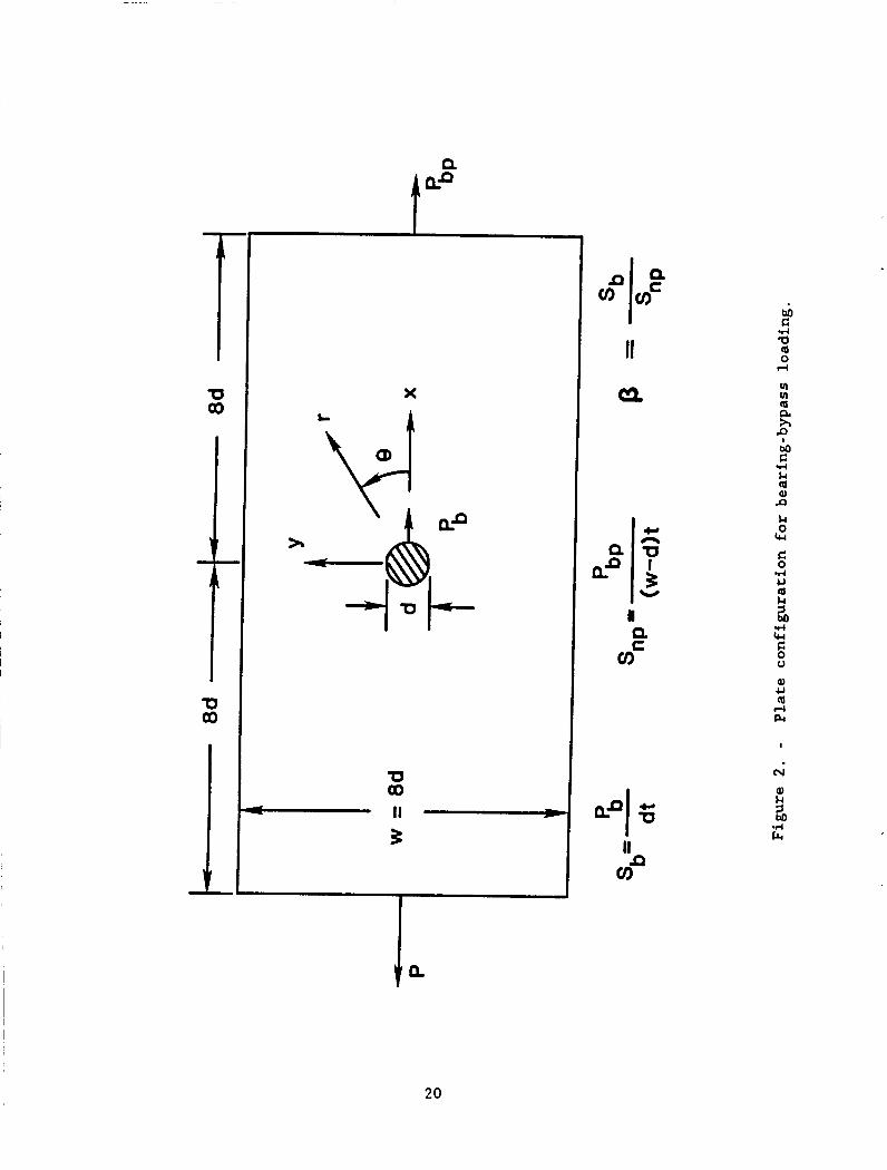
The configuration and loading analyzed in the present study is shown
in figure 2 for a typical tension bearing-bypass case.
P is reacted partly in bearing Pb and partly as a bypass load P at the
other end of the model. The nominal bearing stress Sb and net-section
bypass stress S are defined as shown in figure 2. The bolt was assumed to
be rigid and the bolt-hole interface to be frictionless.
clearance c d the hole diameter d.
The gross applied load
bP
nP The diametrical
between the hole and the bolt was expressed as a percentage of
The material represented in the analysis was a quasi-
isotropic T300/5208 graphite/epoxy laminate with the following properties:
E - 59.46 GPa and G - 20.4 GPa. Isoparametric, quadrilateral and triangular
elements were used to model the laminate (4,131. Nodes were placed at every
0.9375 degrees
Loads P and
bearing-bypass
P bP -
along the
P were
ratio B bP
hole boundary to model the contact angles accurately.
applied to the ends of the model.
was obtained by an appropriate choice of P and
The desired
For a snug-fit joint (cd - 0), the contact angle el along the bolt-
hole interface does not vary with Sb and a simple linear stress analysis can
4
be used. However, for a clearance-fit joint (c > 0), the contact angle
increases nonlinearly with Sb as shown in figure 3. This nonlinear load-
contact variation at the bolt-hole interface greatly complicates the stress
analysis. Bypass loads also influence the nonlinear load-contact variation
further complicating the analysis for combined bearing-bypass loading.
d
Inverse Formulation
The nonlinear load-contact variation shown in figure 3 could be
accounted for in an iterative incremental scheme in which the nominal bearing
stress is incremented in small steps and the corresponding contact angle
d l is determined iteratively at each load step.
require special purpose finite element programming and would also involve
tedious node tracking along the contact arc [9-121. Alternatively, an inverse
technique [ 4 ] can be used in which a contact angle
corresponding bearing stress
described later. The inverse technique is simple to use because the boundary
conditions for an assumed contact angle
outset. For an assumed contact angle, the contact problem is linear, and the
analysis procedure can be repeated for a range of contact angles to determine
a nonlinear load-contact curve like that in figure 3 . Therefore, although the
contact problem is nonlinear, the inverse technique requires only linear
finite element analyses; linear NASTRAN [13] procedures were used to solve
this nonlinear problem. As previously mentioned, the conditions along the
bolt-hole interface were specified by displacement contraint equations. The
formulation of these constraint equations and the solution procedures are
described in the following two sections.
Sb Such a procedure would
fll is assumed and the
Sb is computed by a simple procedure which is
B1 are fixed and known at the
5

Displacement Constraint Equations
Figure 4 shows the analysis model for a typical case of contact at the
bolt-hole interface. The bolt radius r is smaller than the hole radius P
by the amount of radial clearance c . To simplify the analysis, the bolt is
assumed to be fixed in space and the origin of the reference coordinate system
is located at the center of the undeformed hole.
contact occurs only at point A.
P and P , points along the hole boundary which lie within an assumed
contact arc
b
Before load is applied,
After the model is loaded on the two ends by
bP AB contact the frictionless surface of the fixed rigid bolt.
on the hole boundary within the assumed Consider a point P(x,y)
contwt arc AB (see figure 4 ) . Let u and v be the x- and y-
displacements necessary to move point P from its original position to a
point on the surface of the bolt. The deformed position of P may be
described by the following equation:
By expressing x and y in polar coordinates, neglecting the higher order u
and v terms, and noting that rb - R - c, Eq. (1) may be rewritten as
follows :
where
A u + B v - C
A - R c o s B - C
B - R sin B
6

C R c (COS B - 1) (5)
Equation ( 2 ) is a constraint equation for the u- and v-displacements of any
point P(x,y) on the contact arc AB. The quantities A , B , and C can be
computed at the outset since they are functions of the initial geometry. In
the finite element analysis, the displacements of each node within the contact
region can be specified by applying Eq. ( 2 ) as a multi-point constraint [13].
Note that the hole boundary beyond the contact arc is stress free. This fact
will be used later in the analysis.
A s mentioned earlier, for some compression bearing-bypass loads, the
hole tends to close on the bolt leading to dual contact at the bolt-hole
interface. For example, point D on the hole boundary in figure 4 could move
in the positive x-direction and make contact with the bolt surface. This
would correspond to the onset of dual contact. Further loading would lead to
dual contact as shown in figure 5. The contact angles B1 and B 2 for dual
contact would also, in general, vary nonlinearly with load. However, the
inverse technique can also be used for dual contact. Multi-point constraints,
as described by Eq. ( 2 ) , can be used to specify nodal displacements within the
t w o contact regions. The corresponding combination of bearing and bypass
loads can then be determined by the solution procedure described later.
Solution Procedure for Single Contact
The correct bearing stress Sb for an assumed contact angle B1, was
established using a simple procedure and the NASTRAN computer code. Point A
(figure 4), which was assumed to be in contact with the rigid bolt, was fixed.
Displacements of all nodes within the assumed-contact arc were restricted to
those allowed by the multi-point constraints given by Eq. ( 2 ) . Thus all the
7

boundary conditions, including those along the bolt-hole interface, are
defined. However, since the contact angle O1 and the nominal bearing stress
Sb are nonlinearly related, the correct Sb corresponding to the assumed
is still unknown.
For a specified el, the problem is linear and thus, the stresses in the plate are linearly related to Sb and S A linear equation relating
U Sb, and S can be written as nP
rr ' nP
where F1, F2, and F are constants for a given r and 8. The first two
terms in this equation represent the
bearing and bypass loads, respectively. urr due to imposing the rnulti-point constraints and is a function of clearance, as
indicated by Eqs. ( 2 - 5 ) .
3
orr components due to the applied
The third term represents the
For a given bearing-bypass ratio /3 , we can write S as nP
Substituting Eq. ( 7 ) into Eq. (6) gives
The hole boundary region beyond the contact angle is stress free. Thus,
8

This stress boundary condition was imposed at the end of the contact arc as
* If Sb is the correct bearing stress for an assumed contact angle 0 1, then
from Eqs. (8) and (ll), we have the following relation:
This equation can be rewritten as follows:
For a given B , the values of F3(R,B1) and F4(R,B1) were determined
by the following procedure. For an assumed el, the stress Sb was selected
arbitrarily, and was calculated at the end of the contact arc using a
finite element analysis. These S,, and orr values were then used in Eq.
(8) to get one equation for F,(R,B,) and F,,(R,B1). A second Sb was
selected (arbitrarily) and again the corresponding o at the end of the
contact was calculated. The second set of Sb and o values was used in
Eq. (8) to get a second equation for F3(R,B1) and F4(R,B1). The two
equations were solved simultaneously to determine F3(R,B1) and F4(R,d1),
which were then used in Eq. (13) to find
a series of assumed d l values to determine the corresponding Sb values.
These pairs of d l and Sb values can then be plotted to establish
orr
rr
rr
* Sb. This procedure was repeated for
* *
'b
9

versus d 1 curves for single contact in the clearance-fit joint. The above
procedure was introduced and evaluated in reference 4 .
applied for both tension and compression bearing-bypass loads which lead to
single contact.
is described in the next section.
It can be successfully
A slightly different procedure is used for dual contact and
Solution Procedure for Dual Contact
As described earlier, compression bearing-bypass loads may cause dual
contact at the bolt. The dual contact angles 1 9 ~ and d 2 (see figure 5 )
in-rease nonlinearly with load. However, for specified d1 and d 2 , the
stresses in the plate are linearly related to and the bolt-hole ’b ’ ’np’ I
contact stresses associated with the imposed multi-point constraints. A
linear equation relating 0 Sb, and S can be written for the end of rr ’ nP
, each contact arc. For point B (see figure 5),
The constants K1 through K6 are similar to those in Eq. (6). Again, the
first two terms in both Eqs. ( 1 4 ) and (15) represent the 0 components
due to the bearing and bypass loads, respectively. rr
The third term represents
the err associated with the imposed multi-point constraints. Equations (14)
and (15) cannot be simplified further using Eq. ( 7 ) , as was done earlier for
the single-contact case (see Eqs. (6) and (8)), because the bearing-bypass
ratio /l that would lead to contact angles d 1 and d 2 is not known
a priori. The constants K1 through K3 and K4 through K6 can be
I
I 10

determined by calculating arr(R,Ol) and urr(R,r-02) for three different
(arbitrary) combinations of Sb and S The calculated stresses and the
corresponding values of Sb and S are then substituted into Eqs. (14) and
(15) to yield three equations in
K5, and K6.
through K6. Now the correct values of S and S corresponding to the
assumed el and O 2 values can be determined by imposing the boundary
conditions at the ends of the contact arcs as u (R,B1) = 0 and urr(R,n-02)
= 0. Substituting these boundary conditions into Eqs. (14) and (15) we have
nP - nP
K4 *
K1
K1, K2, and K3 and three equations in
These six equations are solved simultaneously to determine
b "P
rr
The only unknowns in the above equations are Sb and S which can be
determined by the simultaneous solution of Eqs. (16) and (17). The above
procedure can be repeated for different sets of assumed contact angles
and e2 to determine the corresponding S,, and S values. These results
can be presented as a Sb versus S plot as discussed in the following "P
section.
nP
nP
RESULTS AND DISCUSSION
All of the results in this paper were obtained for the finite size
of 1.2 percent. First, results 'd plate shown in figure 2 with a clearance
11

are presented for single contact with both tension and compression bearing-
bypass loads. Next, the effect of bypass loading on bolt-hole contact is
shown for a constant bearing loading.
stresses are also presented. Results are then presented for dual contact.
Contact angles are presented on a Sb versus S plot and local stresses
are presented for a dual-contact case.
The corresponding hole boundary
nP
Single Contact
The effect of bearing-bypass ratio B on the bearing stress-contact
angie curves is shown in figure 6 for single contact. Note that p - Q
corresponds to a tension bearing case with no bypass load and p - -a represents the corresponding compression bearing case. The bearing-bypass
ratio
contact angle behavior.
of 400 MPa [ 6 ] , a typical bearing strength for graphite/epoxy, the contact
angle (figure 6 ) for p = 1 is about 30 percent larger than that for p = Q . I;- compression bearing-bypass at
is about 25 percent smaller than that for p = -Q .
/3 was found to have a considerable effect on the bearing stress-
For tension bearing-bypass at a bearing stress level
Sb - 400 MPa, the contact angle for p - -1
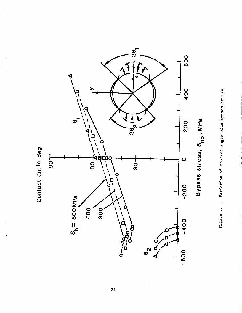
The variation of contact angle with bypass stress is shown in figure 7
’ for three Sb levels. Increasing the tensile bypass loading increased
while increasing the compressive bypass loading had the opposite effect. The
small jog in the curve at S = 0 is caused by the small difference between
tension-reacted bearing and compression reacted bearing.
MPa case, dual contact initiated for a compressive bypass stress of about
450 MPa. The secondary contact angle
compressive S exceeded this value. Additionally, the decreasing trend for
e l
nP For the Sb - 400
increased rather abruptly as the
nP reversed when dual contact developed.
12

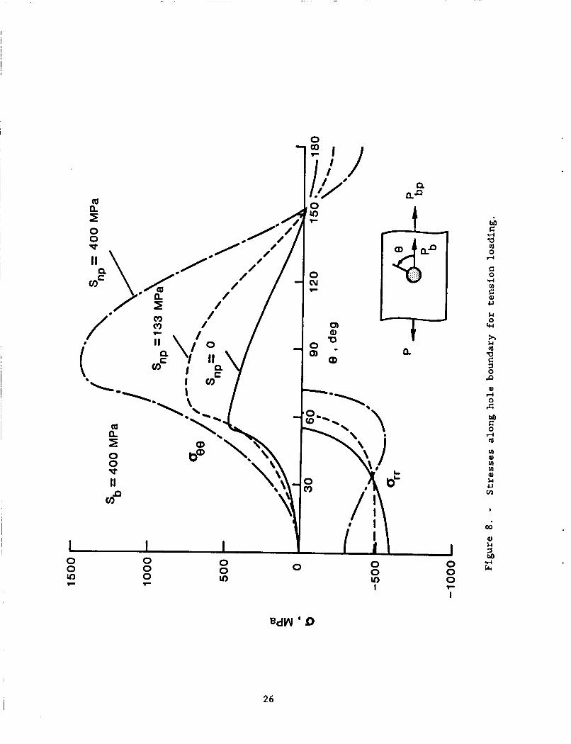
For Sb - 400 MPa, the tangential (as8) and radial (a ) stresses rr around the hole boundary are shown in figure 8 for three different values of
S for tension bearing-bypass loading. The peak value of the a stress
is not very sensitive to S . The arr peak usually occurs at 0 degrees for
small values of S However, the distribution of u changes with nP * rr increased S values, showing the increased contact angle as in figure 7 .
For S - 400 MPa, the urr peak occurs at around 55 degrees. The increase
in the peak age
S stress. The location of the peak oBB is usually a few degrees beyond
the contact region. The location of the a peak is important because
damage in composite joints often starts at this location [ 5 ] .
nP rr
nP
nP
nP stresses rises nearly proportionally with the increase in
nP
d e
The uB8 and u hole boundary stresses for compressive S rr nP
stresses are shown in figure 9. For S = 0 (/I - -a), ag8 is mostly tensile. For S - -133 MPa, a88 becomes compressive in the net-section
(around 90 ) of the joint. For S = -400 MPa, the compression peak of u
is larger and more of the hole boundary is in compression. Unlike the tension
bearing-bypass cases, the peak value of the a stress in compression
bearing-bypass increases nearly proportionally with the bypass load and always
occurs at t9 = 0 . For example the peak arr stress for S - 400 MPa is
40 percent higher than the S - 0 case.
nP
"P 0
88 nP
rr
0
"P
nP
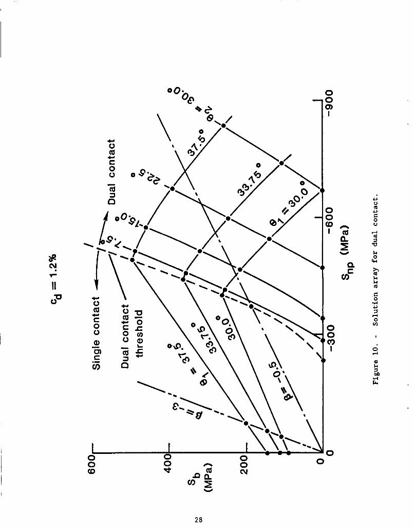
Dual Contact
The Sb and S values calculated for assumed values of B1 and nP
8*
solution corresponding to assumed contact angles B1 and e2 . The dashed
curve represents the onset of dual contact. The region to the right of the
dashed curve represents the dual-contact region.
are plotted in figure 10. Each solid circular symbol represents a
The double-dashed line
13

represents the B = -3 case. Note that this line runs almost parallel to the
linear portion of the dual-contact threshold line (dashed line), indicating
that the p - - 3 case would never involve dual contact. Thus, dual contact
would occur only when - 3 < p I O . The dashed-dot line represents the
p - - 0 . 5 case. It intersects the dual-contact curve (dashed) at S - - 3 7 5 nP
MPa. Thus dual contact for this case would begin at S - -375 MPa
(Sb = 187.5 MPa).
clearance of 1.2 percent of hole diameter.
nP I
I Note that all the results in figure 10 were obtained for a
A smaller clearance would cause
dual contact to develop at a lower load level and vice versa.
The effect of dual contact on the Sb versus dl curve is shown in
figure 11. The Sb versus B1 curve before dual contact was generated using
the procedure for single-contact analysis described earlier. The remainder of
the curve was constructed from figure 10 by selecting Sb, B1, and e 2 values
on the /3 - - 0 . 5 line. Some interpolation was used. The Sb versus
relationship changes after the onset of dual contact. The Sb versus
curve is also nonlinear and B 2 increases more rapidly than B1 with
increasing load.
g2
An important consequence of dual contact is that it allows load
transfer across the bolt and, therefore, reduces the stress concentration
around the fastener hole. Figure 12 illustrates this effect by comparing
hole boundary stresses for a case with dual contact to stresses for an open
hole case at the same load level.
percent higher than that for the dual-contact case.
contact is advantageous since it reduces stresses around the hole and
increases the joint strength. Smaller bolt-hole clearances promote dual
contact and, therefore, should produce higher joint strengths in compression.
The peak age for the open hole case is 13
This suggests that dual
14

I
CONCLUDING REMARKS
A simple method has been developed for the stress analysis of a
laminate with a clearance-fit fastener subjected to combined bearing and
bypass loading in tension or compression, including dual-contact situations.
This method uses a linear elastic finite element analysis with an inverse
formulation.
with most general purpose finite element programs.
study the effects of bearing-bypass load proportioning on the bolt-hole
contact angles and local stresses. The initial clearance between the smooth,
rigid bolt and the hole was 1 . 2 percent of the hole diameter in all analyses.
Material properties for the plate represented a quasi-isotropic,
graphite/epoxy laminate.
terms of 8, the ratio of bearing stress Sb to bypass stress S
The present method is simple to apply and can be implemented
The method was applied to
The bearing-bypass proportions were expressed in
nP The bearing-bypass ratio /3 was found to have a considerable effect
on the nonlinear contact behavior.
Sb - 400 MPa, the contact angle was 30 percent larger for /3 = a. Compressive bypass loading had the opposite effect, the contact angle
was 25 percent smaller for /3 = -1 than that for /3 - - w at Sb - 400 MPa. For single-contact situations under tension bearing-bypass, the peak
tangential stresses around the hole boundary increased proportionately with
the S stress. The peak radial stress was not very sensitive to S
However, under compressive bearing-bypass loading, both the peak tangential
and peak radial stresses were considerably influenced by S . For /3
greater than - 3 , the hole tended to close on the fastener leading to dual
Under tension bearing-bypass with
fl - 1 than that for
nP nP'
"P
1 5
contact. Dual contact allows load transfer across the fastener and,
therefore, reduces the stress concentration around the hole. Dual contact,
therefore, has a beneficial effect on the joint strength.
These results illustrate the general importance of accounting for
bolt-hole clearance and contact to accurately compute local bolt-hole stresses
for combined bearing and bypass loading.
16
REFERENCES
1. Ramkumar, R. L.: "Bolted Joint Design, Test Methods and Design
Allowables for Fibrous Composites," ASTM STP 734, C. C. Chamis, Ed.,
1981, pp. 376-395.
2. Soni, S . R.: "Stress and Strength Analysis of Bolted Joints in
Composite Laminates," Composite Structures, Ed. I. H. Marshall,
Applied Science Publishers, London and New Jersey, 1981, pp 50-62.
3 . Garbo, S . P.; and Ogonowski, J. M.: "Effect of Variances and
Manufacturing Tolerances on the Design Strength and Life of
Mechanically Fastened Composite Joints,"
Data Evaluation, AFWAL-TR-81-3041, Vols. 1-111, April 1981.
Methodology Development and
4. Naik, R. A.; and Crews, J. H., Jr.: "Stress Analysis Method for a
Clearance-Fit Bolt Under Bearing Loads," A I M Journal, Vol. 24, No.
8, Aug. 1986, pp. 1348-1353.
5. Crews J. H. Jr.; and Naik R. A.: "Failure Analysis of a Graphite/Epoxy
Laminate Subjected to Bolt Bearing Loads." Composite Materials:
Fatigue and Fracture, ASTM STP 907, H. T. Hahn, Ed., American Society
for Testing and Materials, Philadelphia, 1986, pp. 115-133. Also
published as NASA TM-86297, Aug. 1984.
6. Crews, J. H., Jr.; and Naik, R. A.: "Combined Bearing and Bypass
Loading on a Graphite/Epoxy Laminate," Composite Structures, Vol. 6,
Nos. 1-3, 1986, pp. 21-40. Also published as NASA TM-87705, April
1986.
17

7. Eshwar, V. A.: "Analysis of Clearance Fit Pin Joints," International
Journal of Mechanical Sciences, Vol. 20, 1978, pp. 477-484.
8 . Mangalgiri, P. D.; Dattaguru, B.; and Rao, A. K.: "Finite Element
Analysis of Moving Contact in Mechanically Fastened Joints," Nuclear
Engineering Design, Vol. 7 8 , 1984, pp. 303-311.
9. Francavilla, A.; and Zienkiewicz, 0. C.: "A Note on Numerical
Computation of Elastic Contact Problems," International Journal for
Numerical Methods in Engineering, Vol. 9, 1975, pp. 913-924.
10. White, D. J.; and Enderby, L. R.: "Finite Element Stress Analysis of a
Nonlinear Problem: A Connecting-Rod Eye Loaded by Means of a Pin,"
Journal of Strain Analysis, Vol. 5, No. 1, 1970, pp. 41-48.
11. Sholes, A.; and Strover, E. M.: "The Piecewise-Linear Analysis of Two
Connecting Structures Including the Effect of Clearance at the
Connections," International Journal for Numerical Methods in
Engineering, Vol. 3 , 1971, pp. 45-51.
12. Chan, S . K.; and Tuba, I. S . : "A Finite Element Method for Contact
Problems of Solid Bodies - Part I. Theory and Validation,"
International Journal of Mechanical Sciences, Vol. 13, 1971, pp. 615-
625.
1 3 . MSC/NASTRAN, User's Manual, Vol. 1 and 2, MSR-39, Nov. 1985, The
MacNeal-Schwendler Corporation, Los Angeles, California.
18

I \ I
c 0
I O 0 0 0 i I I o 0 0 0 I I
c, c al-4 0 -m k
Q) 4J In (d cer
. I4 4J rl
E
I
2
s (d
c .rl
nl-4 3 M c .I4 a (d 0 rl
v) In (d a h P
I
M C
.I4
I
d
19
T 0
00 x
U 00 - I I 3
P na
I
n U
I W
2 .d a a 0 rl
k 0 4-4
4 L) ki k 3 M
I
(v
Q) 8.4 3 M .d c4
20

x
C
a t
- u3 v) W
I- u3
a
0
n wl
u
a 5
21

P
t I
4
l-
x
IJ 'cl 0
U 0 Q U e 0 0
E rl u Q u
Q)
I
*
22

a
a! 0 a u C 0
2 a u r) a u c 0 0
I
In
23

0
\' 1
24
,
I t v
I I I 0 c9
I I
I I
0 Q)
0 0 a
0 0 w
0 0 cv
0
0 0 cv I
0 0 w
I
0
R P
.d u cd ..-I i; cd 3
I
Q) k
.d zl crr
I
25
I I I 0 0 v) F
0
u
h Ll cd a s 0 P 0) d 0 c
k u v1
I
00
26

0 0
UP
0 Iv) :\ \ ' .\
0,
L ".b" ...;.. .: ::. ..... .. . .
T Q
E: 0
.I4 m ul Q) k
0 c)
2 k 0 cw h k ld Q
5 0 Ji aJ d 0 c M
k U (A
27
0 3 3) I
0 0 o n l a e 2 U
Q
a=
0 0 rn
I
0
u 0 Id u C 0 0
k-l Id 1 a &4 0 cw
0
W
28

\ 0
I I I I I 0 0 0 0 0 - 0 rc)
0 d=
0 c')
0 cu 0
0 cu
h
29

n
a e r
I \ (
0 w I I I 1
0 :v) 'F
0 0 v)
0 0 0 l-
0 0 v)
0
I
u) 0) u) u) Q) k U L4
9-i k ld Q
0 P Q)
I 4
5
e E: 0
u 0 ld U G 0 L)
l-l ld 3 a cer 0
u
BdW
30
Report Documentation Page 1. Report No. 2. Government Accession No. 3. Recipient’s Catalog No.
NASA TM-100551 4. Title and Subtitle
Stress Analysis Method for Clearance-Fit Joints With Bearing-Bypass Loads
5. Report Date
6. Performing Organization Code c 7. Authorls) 8. Performing Organization Report No.
R. A. Naik and J. H. Crews, Jr.
NASA Langley Research Center Hampton, VA 23665-5225
10. Work Unit No.
11. Contract or Grant No.
12. Sponsoring Agency Name and Address 13. Type of Report and Period Covered
Technical Memorandum National Aeronautics and Space Administration Washington, DC 20546
l J 15. Supplementary Notes
14. Sponsoring egency Code e
Unclassified Unclassified 31 A03
16. Abstract
Within a multi-fastener joint, fastener holes may be subjected to the combined effects of bearing loads and loads that bypass the hole to be reacted elsewhere in the joint. The analysis of a joint subjected to such combined bearing and bypass loads is complicated by the usual clearance between the hole and the fastene A simple analysis method for such clearance-fit joints subjected to bearing-bypass loading has been developed in the present study. It uses an inverse formulation with a linear elastic finite-element analysis. Conditions along the bolt-hole contact arc are specified by displacement constraint equations. The present method is simple to apply and can be implemented with most general purpose finite-element programs. since it does not use complicated iterative-incremental procedures. The method was used to study the effects of bearing-bypass loading on bolt-hole contact angles and local stresses. In this study, a rigid, frictionless bolt was used with a plate having the properties of a quasi-isotropic graphite/epoxy laminate. Results showed that the contact angle as well as the peak stresses around the hole and their locations were strongly influenced by the ratio of bearing and bypass loads. For single contact, tension and compression bearing-bypass loading had opposite effects on the contact angle. For some compressive bearing-bypass loads, the hole tended to close on the fastener leading to dual contact. It was shown that dual contact reduces the stress concentration at the fastener and would, therefore, increase joint strength in com- Dression. The results illustrate the general imortance of accounting for bolt-hole clearance and and contac
Y
Stress analysis Finite-elements Bearing-bypass clearance
20. Security Classif. (of tl
Y
Unclassified - Unlimited Subject Category - 24
s Pawl I 21. NO. of pa& 122. Price 1