nasa langley’s airstar testbed – a subscale flight test ... · capability for flight dynamics...
TRANSCRIPT

NASA Langley’s AirSTAR Testbed – A Subscale Flight Test Capability for Flight Dynamics and Control System
Experiments
Thomas L. Jordan* and Roger M. Bailey.†
NASA Langley Research Center, Hampton VA 23681
As part of the Airborne Subscale Transport Aircraft Research (AirSTAR) project, NASA Langley Research Center (LaRC) has developed a subscaled flying testbed in order to conduct research experiments in support of the goals of NASA’s Aviation Safety Program. This research capability consists of three distinct components. The first of these is the research aircraft, of which there are several in the AirSTAR stable. These aircraft range from a dynamically-scaled, twin turbine vehicle to a propeller driven, off-the-shelf airframe. Each of these airframes carves out its own niche in the research test program. All of the airplanes have sophisticated on-board data acquisition and actuation systems, recording, telemetering, processing, and/or receiving data from research control systems. The second piece of the testbed is the ground facilities, which encompass the hardware and software infrastructure necessary to provide comprehensive support services for conducting flight research using the subscale aircraft, including: subsystem development, integrated testing, remote piloting of the subscale aircraft, telemetry processing, experimental flight control law implementation and evaluation, flight simulation, data recording/archiving, and communications. The ground facilities are comprised of two major components: (1) The Base Research Station (BRS), a LaRC laboratory facility for system development, testing and data analysis, and (2) The Mobile Operations Station (MOS), a self-contained, motorized vehicle serving as a mobile research command/operations center, functionally equivalent to the BRS, capable of deployment to remote sites for supporting flight tests. The third piece of the testbed is the test facility itself. Research flights carried out by the AirSTAR team are conducted at NASA Wallops Flight Facility (WFF) on the Eastern Shore of Virginia. The UAV Island runway is a 50’ x 1500’ paved runway that lies within restricted airspace at Wallops Flight Facility. The facility provides all the necessary infrastructure to conduct the research flights in a safe and efficient manner. This paper gives a comprehensive overview of the development of the AirSTAR testbed.
I. Introduction he NASA Aviation Safety Program (AvSP) was established to improve the safety of current and future aircraft in the National Airspace System (NAS) by focusing on the design, manufacture, maintenance, and operation of
aircraft and to develop the technologies to overcome the barriers to the Next Generation Air Transportation System (NGATS)1,2. Two projects within the AvSP, Integrated Resilient Aircraft Control (IRAC) and Integrated Vehicle Health Management (IVHM), together are working to prevent loss-of-control accidents and to identify and mitigate the contributing factors in these types of accidents. Technologies being developed include enhanced models of vehicle dynamics to characterize upset conditions, failure detection and identification (FDI) algorithms, and adaptive guidance and control (G&C) laws. The flight dynamics models for upset conditions have been developed for integration into an enhanced aircraft simulation that is being created for improved upset recovery training, and to support the development and evaluation of the FDI and G&C algorithms3. These algorithms are being developed for use onboard transport aircraft for improved situational awareness and control under adverse and upset conditions related to loss-of-control events. Validation of these technologies is therefore critical. Figure 1 illustrates how an
T
American Institute of Aeronautics and Astronautics
092407
1
* Systems Engineer, Aeronautic Systems Engineering Branch, M/S 238, AIAA member † Senior Research Engineer, Safety Critical Aviation Systems Branch, M/S 130, AIAA member.
https://ntrs.nasa.gov/search.jsp?R=20080034482 2018-06-01T17:00:18+00:00Z

actual loss-of-control accident goes beyond the normal flight envelope into regions where aerodynamic data is not available from conventional sources.
The AirSTAR testbed has been developed to provide an in-flight capability to validate various flight critical technologies4. The testbed is composed of three elements: the Air Facilities, a stable of airframes and associated avionics and instrumentation; the Ground Facilities, which include a Mobile Operations Station (MOS) and associated ground based support equipment5, and a test range. This research capability, along with wind tunnel testing, full scale flight testing, and flight simulation, provides the methods and tools to develop and test the technologies demanded by the AvSP.
0
10º
20º
30º
40º
50º
-40º -30º -20º -10º 0º 10º 20º 30º 40º0
10º
20º
30º
40º
50º
-40º -30º -20º -10º 0º 10º 20º 30º 40º0
10º
20º
30º
40º
50º
0
10º
20º
30º
40º
50º
-40º -30º -20º -10º 0º 10º 20º 30º 40º-40º -30º -20º -10º 0º 10º 20º 30º 40º
Angle of sideslip - deg
Ang
le o
f att
a ck
-deg
Loss-Of-Control Accident data
Normal Flt envelopeCurrent
wind tunnel data envelope
Extrapolated data envelope
Figure 1. Transport loss-of-control accident relative to angle-of-
attack and sideslip.
The expanded flight envelope of the AirSTAR vehicles and the requirements to gather large amounts of data (at high rates) presented unique challenges to the development of the AirSTAR testbed. While most Unmanned Aerial Vehicles (UAVs) constrain
their flight envelope to rather benign attitudes (due mainly to their role as reconnaissance aircraft), these research airframes and control systems are intended to fly in very demanding conditions, both structurally and control wise. This requirement invokes additional measures in the airframes and flight control systems that set the AirSTAR testbed apart from most UAVs.
The remainder of this paper is organized as follows: Section II describes various Air Facilities; Section III discusses the Mobile Operation Station and associated Ground Facilities; Section IV provides insight into the identification of and relationship with the test facility; Section V talks about the Concept-of-Operation of the AirSTAR testbed and Section VI provides some concluding remarks.
II. Air Facilities The Air Facilities portion of the AirSTAR testbed consists of a variety of airframes and data/control systems,
each with its own unique research capabilities. However the following features are characteristic of all the AirSTAR Air Facilities components:
1) Airframes which are 75 lbs or less 2) Wingspans of 8 ft or smaller 3) Turbine or propeller driven 4) Operated by a safety and/or research pilot within visual range 5) Onboard data acquisition and/or recording capability 6) Inertial, GPS, airspeed, altitude, and control surface position sensors
A. Airframes The most sophisticated and complex airframe within the testbed is a 5.5% dynamically scaled generic transport
model6. This airframe has a takeoff weight of approximately 55 lbs, a wingspan of 82 inches, is powered by two small turbine engines, and is pictured in Fig. 2 below. This specialized airframe was designed and built at Langley Research Center. By adhering to the properties of similitude, the properties of an object of one size (a subscale
American Institute of Aeronautics and Astronautics
092407
2

airplane) can be mathematically related to the properties of an object of another size (a full scale airplane)7-8. For a scale factor of K equal to 0.055, the subscale response is related to the full scale response by a factor of K , or approximately 4.26. That is, the subscale model will respond 4.26 times faster than the full scale airframe. The 5.5% scale factor was chosen based on a number of factors including the existence of a large database of wind tunnel data for this scale airframe and a feasibility study which was conducted that determined the structural and payload requirements for a research vehicle could be met at that scale. For the experiments that the AirSTAR testbed will be used for, such as loss-of-control flight due to high angles-of-attack and sideslip, the flow around the aircraft becomes separated and fluid effects associated with Reynolds number scaling may be minimized9. For more benign flight conditions, Reynolds number effects can be significant and the aerodynamics of the model would not be representative of the full scale aircraft for certain maneuvers.
American Institute of Aeronautics and Astronautics
092407
3
In addition to the dynamically scaled airframe described above, the testbed also has a commercial-off-the-shelf
(COTS) transport model, powered by a single turbine engine, weighing approximately 48 lbs and with a wingspan of 85 inches. A picture of the airplane in flight is shown in Fig. 3. While this model is not dynamically scaled, it was designed to have favorable flying qualities at this size and weight. And because the airframe kit is commercially available, both the cost and maintenance of the airplane is significantly reduced compared to the one-of-a-kind dynamically scaled vehicle. This airframe has been particularly useful in testing out various hardware and software applications before migrating those technologies to the dynamically scale airframe. Recently, the airframe has been used for real-time parameter identification, modeling, and fault detection research experiments.
a) b) Figure 2. 5.5% Dynamically scaled Generic Transport Model, a) solid model and b) in flight.
Figure 3. AirSTAR S2 research aircraft during flight testing

A third type of airframe within the AirSTAR testbed is the small, propeller driven, COTS airframe. While there are several different types of these airframes utilized by the AirSTAR project, they all offer a very inexpensive, easy to fly and maintain, and robust platform for hosting research data and control systems. This group of vehicles is collectively referred to as the Rapid Evaluation Class (REC). Pictured in Fig. 4 is one of these airframes, the Free-flying Aircraft for Subscale Experimental Research (FASER)10. These aircraft were developed to conduct frequent flight test experiments for research and demonstration of advanced dynamic modeling and control design concepts. In keeping with the spirit of these low-cost airframes, the infrastructure to support, operate, and maintain these aircraft is kept to a minimum.
Figure 4. Low-cost FASER research aircraft
B. Data, Control, and Instrumentation Systems There are two basic data and control systems which are utilized in the AirSTAR project. The first is a dedicated,
proprietary system which is integrated into the turbine vehicles. This system was designed to meet specific dynamic scaling requirements. The second is an open architecture, PC-based system which has been customized to the specific geometric, electrical, environmental, and research requirements of the propeller based airframes. These two systems and the associated instrumentation are described below.
1. Dynamically Scaled Data and Control Dynamic scaling applies not only to the geometric and mass properties of an aircraft, but also to the control and
actuation systems. As mentioned above, the 5.5% dynamically scaled vehicle responds approximately 4.26 times faster than the full scale vehicle. Therefore, the data acquisition, control, and actuation systems must also be scaled up in time (made faster) by this same factor. Scaling from the full scale flight control system, this equates to a data acquisition and control rate of approximately 200 Hz. Because of the ambitious real-time computing requirements, the limited space and weight budget of the model, and the inherent risk in flight beyond the normal envelope, the system was designed to have the data acquisition function, shown in Fig. 5, on board the plane, but to have the flight control computer reside on the ground. This decision to remotely control the airplane has both benefits and drawbacks. The benefits include removing the flight control system from the cramped and environmentally harsh environment inside the model while also eliminating the risk of losing the system in the event of a crash. However, this places additional requirements on the telemetry system to deliver the data to the ground and send control signals back to the plane with minimal interruptions. The outputs of the ground based flight control system (basically throttle and control surface commands) are computed on the ground and sent up to the plane where they are routed to the appropriate actuators by the safety switch. The ground based portion of this control system is discussed in more detail in Section III, Ground Facilities.
Figure 5. Data system for dynamically scaled aircraft
This data system has 48 channels of 16-bit analog to digital converters, two bytes of discrete digital input/output (I/O), and three serial communication channels. In addition, there is a programmable safety switch that transfers
American Institute of Aeronautics and Astronautics
092407
4
control between the safety pilot and research pilot based on an uplink command from the safety pilot. This switch can control up to 32 servos or other PWM devices.
2. Open Architecture Data and Control Because the REC aircraft are meant to provide an inexpensive and rapid testbed for flight control testing, the
data and control system chosen for these vehicles must meet those same criteria. For those reasons, a PC104 based system was selected for the flight computer. PC104 systems utilize the standard 16-bit ISA bus and Intel compatible 486/586 processors that are common in desktop computers. This standardization allows easy integration of third party interface cards for such tasks as analog to digital I/O, digital counters, and serial and network communication. Another advantage of this architecture is the availability of operating systems and other software. For the REC vehicles, the xPC-Target toolbox form Mathworks, Inc was chosen as the real time operating system. This also allows the processor to execute compiled Simulink® diagrams. This integration of COTS hardware and software eases the transition from simulation to flight testing for controls and system identification engineers developing software for flight research.
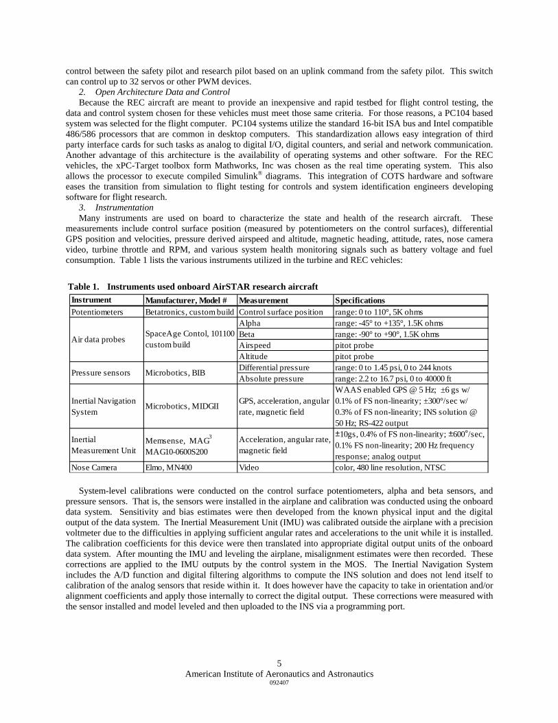
3. Instrumentation Many instruments are used on board to characterize the state and health of the research aircraft. These
measurements include control surface position (measured by potentiometers on the control surfaces), differential GPS position and velocities, pressure derived airspeed and altitude, magnetic heading, attitude, rates, nose camera video, turbine throttle and RPM, and various system health monitoring signals such as battery voltage and fuel consumption. Table 1 lists the various instruments utilized in the turbine and REC vehicles:
Table 1. Instruments used onboard AirSTAR research aircraft Instrument Manufacturer, Model # Measurement SpecificationsPotentiometers Betatronics, custom build Control surface position range: 0 to 110°, 5K ohms
Alpha range: -45° to +135°, 1.5K ohmsBeta range: -90° to +90°, 1.5K ohmsAirspeed pitot probeAltitude pitot probeDifferential pressure range: 0 to 1.45 psi, 0 to 244 knotsAbsolute pressure range: 2.2 to 16.7 psi, 0 to 40000 ft
Inertial Navigation System
Microbotics, MIDGII GPS, acceleration, angular rate, magnetic field
WAAS enabled GPS @ 5 Hz; ±6 gs w/ 0.1% of FS non-linearity; ±300°/sec w/ 0.3% of FS non-linearity; INS solution @ 50 Hz; RS-422 output
Inertial Measurement Unit
Memsense, MAG3
MAG10-0600S200Acceleration, angular rate, magnetic field
±10gs, 0.4% of FS non-linearity; ±600°/sec, 0.1% FS non-linearity; 200 Hz frequency response; analog output
Nose Camera Elmo, MN400 Video color, 480 line resolution, NTSC
Pressure sensors Microbotics, BIB
Air data probesSpaceAge Contol, 101100 custom build
System-level calibrations were conducted on the control surface potentiometers, alpha and beta sensors, and
pressure sensors. That is, the sensors were installed in the airplane and calibration was conducted using the onboard data system. Sensitivity and bias estimates were then developed from the known physical input and the digital output of the data system. The Inertial Measurement Unit (IMU) was calibrated outside the airplane with a precision voltmeter due to the difficulties in applying sufficient angular rates and accelerations to the unit while it is installed. The calibration coefficients for this device were then translated into appropriate digital output units of the onboard data system. After mounting the IMU and leveling the airplane, misalignment estimates were then recorded. These corrections are applied to the IMU outputs by the control system in the MOS. The Inertial Navigation System includes the A/D function and digital filtering algorithms to compute the INS solution and does not lend itself to calibration of the analog sensors that reside within it. It does however have the capacity to take in orientation and/or alignment coefficients and apply those internally to correct the digital output. These corrections were measured with the sensor installed and model leveled and then uploaded to the INS via a programming port.
American Institute of Aeronautics and Astronautics
092407
5

American Institute of Aeronautics and Astronautics
092407
6
Figure 6. Block Diagram of AirSTAR Ground Facilities
from upset conditions) will require a robust and reliable ground support systemsection describes the ground facilities being developed to support the NASA Latestbed. Figure 6 shows a functional diagram of the basic AIRSTAR-Ground Facil
1)
5)
6) ime test article
the NASA Langley ReLab toand to su
f deployment to remote sites when conducting AIRSTAR flight
including the BRS/MOS interaction. Figure 8 shows a test article during MOS rSTAR-GF “hot bench.” mprised of three major hardware subsystems: the air-ground data link, the computational
resources, and the user interfaces:
A. Air-Ground Datalink Communications between the AirSTAR aircraft and the AIRSTAR-GF are via a duplex serial data link using
microwave RF transceivers with a separate safety-pilot backup command RF link. To maintain effective telemetry communications coverage, the AIRSTAR-GF will employ a directionally-tracked, circularly-polarized antenna
III. Ground Facilities Use of a Remotely Piloted Vehicle (i.e. the test article) for conducting flight tests to validate control upset
prevention and recovery technologies (including modeling and control methods for characterizing and recovering for pilots and researchers. This ngley Research Center AirSTAR ities (AIRSTAR-GF) architecture.
The fundamental purpose of the AIRSTAR-GF is to provide
apparatus to accomplish thethe following:
Permit research pilots to control the test article
2) Receive, process, record and transmit test article telemetry data
3) Display information to pilots, researchers, systems engineers and observers Provide
Functionality
simulation for training, testing and experiment reproduction
The AIRSTAR Ground Facilities are designed to align with the overall development of
4) voice communications for experiment participants and observers Provide data processing systems capable of computing control parameters on the ground to augment pilot control and/or remotely drive aircraft control surfaces Provide real-t
search Center Systems and Airframe Failure Emulation, Testing and Integration (SAFETI) Research ora ry11. The SAFETI Lab is being developed for validation testing of Aviation Safety Program technologies
pport long-term Aviation Safety Program experimental research goals and objectives. AIRSTAR-GFThe are the conjugation of two separate resources:
1) The Mobile Operations Station (MOS) - a self-contained, motorized vehicle serving as a mobile research command/operations center, capable oexperiments.
2) The Base Research Station (BRS) - a laboratory based at the NASA Langley Research Center providing near-identical capabilities as the MOS.
The MOS functions as the command and control center during flight testing in the field, whereas the BRS is used for experimental software development and testing, and includes a “hot bench” work area which accommodates hardware-in-the-loop integration, test and evaluation with the test article. Figure 7 provides an overview of the AIRSTAR-GF Hardware Systems integration testing in the Ai
The AIRSTAR-GF is co

Figure 7. AIRSTAR-GF Hardware Systems Overview
sys
Figure 8. Test Article Integration Testing in the AirSTAR-GF “hot bench”
tem. Analysis of the anticipated RF budget (involving transmitter powers, receiver noise floors, and antenna gains) supports the desired operation of the microwave links to slant ranges up to two statue miles with power margins in excess of 15 decibels. The AirSTAR telemetry system evolved from an air-to-ground datalink system developed by Microbotics Inc., and utilizes a proprietary encoding scheme based on the IRIG-106 standard. The telemetry system is comprised of a custom built Telemetry Airborne Unit (TAU) installed in the test article and a custom built Telemetry Ground Unit (TGU) interfaced to the AIRSTAR-GF. The on-board TAU is microprocessor-based, and incorporates hardware to assist in aircraft operations and instrumentation, including signal interface boards, safety switch, and power supplies. The TAU acquires data from various sensors aboard the test article, including transducers indicating flight surfaces position, angle-of-attack probes, engine control units (ECU), MIDG II‡, battery status, and employs a ‘Flight Controller’ module to multiplex this data for the air-to-ground telemetry stream. Conversely, the ‘Flight Controller’ module is used to de-multiplex the ground-to-air telemetry stream, distributing commands to AIRSTAR subsystems, including the flight surface servos. Additionally, video from the test article’s nose camera will be transmitted via the RF link to the ground.
The TGU’s primary function is to perform the multiplexing and de-multiplexing of the telemetry data for AIRSTAR-GF client computers, and is housed in a standard 19” rack-mountable enclosure. The TGU interfaces to the AIRSTAR-GF computing system via four asynchronous serial
American Institute of Aeronautics and Astronautics
092407
7
‡ The MIDG II is a product from Microbotics Inc. which outputs GTM rotational rates, attitude, accelerations, GPS velocity and position, inertial navigation velocity and position (filtered velocity and position from GPS measurements and inertial measurements), magnetometer data, and GPS satellite data, all in a very small, lightweight package.
American Institute of Aeronautics and Astronautics
8
092407
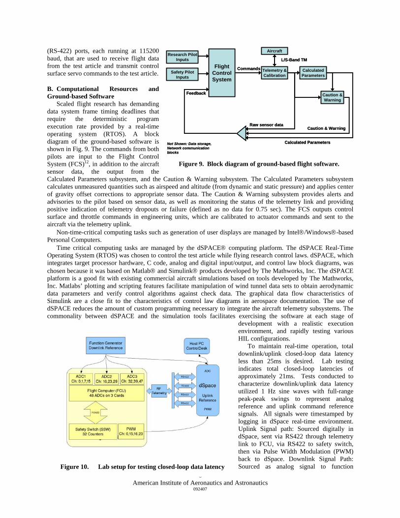
Figure 10. Lab setup for testing closed-loop data latency
fro
he commands from both pilots are input to the Flight Control
ut from the Ca
ACE® computing platform. The dSPACE Real-Time Op
ssor hardware, C code, analog and digital input/output, and control law block diagrams, was cho
desired. Lab testing ind
(RS-422) ports, each running at 115200 baud, that are used to receive flight data
m the test article and transmit control surface servo commands to the test article.
B. Computational Resources and Ground-based Software
Scaled flight research has demanding data system frame timing deadlines that require the deterministic program execution rate provided by a real-time operating system (RTOS). A block diagram of the ground-based software is shown in Fig. 9. T
FlightControlSystem
Telemetry &Calibration
Research PilotInputs
Safety PilotInputs
Caution &Warning
CalculatedParameters
Caution & Warning
Calculated Parameters
Commands
Not Shown: Data storage, Network communication blocks
Feedback
Raw sensor data
Aircraft
L/S-Band TMFlight
ControlSystem
Telemetry &Calibration
Research PilotInputs
Safety PilotInputs
Caution &Warning
CalculatedParameters
Caution & Warning
Calculated Parameters
Commands
Not Shown: Data storage, Network communication blocks
Feedback
Raw sensor data
Aircraft
L/S-Band TM
System (FCS)12, in addition to the aircraft sensor data, the outp
Figure 9. Block diagram of ground-based flight software.
lculated Parameters subsystem, and the Caution & Warning subsystem. The Calculated Parameters subsystem calculates unmeasured quantities such as airspeed and altitude (from dynamic and static pressure) and applies center of gravity offset corrections to appropriate sensor data. The Caution & Warning subsystem provides alerts and advisories to the pilot based on sensor data, as well as monitoring the status of the telemetry link and providing positive indication of telemetry dropouts or failure (defined as no data for 0.75 sec). The FCS outputs control surface and throttle commands in engineering units, which are calibrated to actuator commands and sent to the aircraft via the telemetry uplink.
Non-time-critical computing tasks such as generation of user displays are managed by Intel®/Windows®-based Personal Computers.
Time critical computing tasks are managed by the dSPerating System (RTOS) was chosen to control the test article while flying research control laws. dSPACE, which
integrates target procesen because it was based on Matlab® and Simulink® products developed by The Mathworks, Inc. The dSPACE
platform is a good fit with existing commercial aircraft simulations based on tools developed by The Mathworks, Inc. Matlabs’ plotting and scripting features facilitate manipulation of wind tunnel data sets to obtain aerodynamic data parameters and verify control algorithms against check data. The graphical data flow characteristics of Simulink are a close fit to the characteristics of control law diagrams in aerospace documentation. The use of dSPACE reduces the amount of custom programming necessary to integrate the aircraft telemetry subsystems. The commonality between dSPACE and the simulation tools facilitates exercising the software at each stage of
development with a realistic execution environment, and rapidly testing various HIL configurations.
To maintain real-time operation, total downlink/uplink closed-loop data latency less than 25ms is
icates total closed-loop latencies of approximately 21ms. Tests conducted to characterize downlink/uplink data latency utilized 1 Hz sine waves with full-range peak-peak swings to represent analog reference and uplink command reference signals. All signals were timestamped by logging in dSpace real-time environment. Uplink Signal path: Sourced digitally in dSpace, sent via RS422 through telemetry link to FCU, via RS422 to safety switch, then via Pulse Width Modulation (PWM) back to dSpace. Downlink Signal Path: Sourced as analog signal to function
generator, read into FCU ADCs, sent via telemetry to RS422 to dSpace and compared with direct dSpace ADC measurement. Latency measurements were:
1) Downlink: 6 msec
American Institute of Aeronautics and Astronautics
092407
9
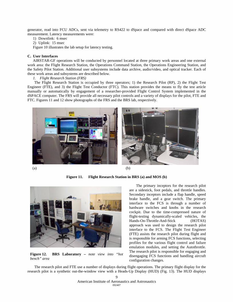
(a) (b)
Figure 11. Flight Research Station in BRS (a) and MOS (b)
igure 12. BRS Laboratory – note view into “hot
e lab setup for latency testing.
C. User Interfaces erations will be conducted by personnel located at three primary work areas and one external
wo
cupied by three operators; 1) the Research Pilot (RP), 2) the Flight Test Engi
The primary inceptors for the research pilot are
The research pilot and FTE use a number of displays during fl mary flight display for the research pilot is a synthetic out-the-window view with a Heads-Up Display (HUD) (Fig. 13). The HUD displays
2) Uplink: 15 msec Figure 10 illustrates th
AIRSTAR-GF oprk area: the Flight Research Station, the Operations Command Station, the Operations Engineering Station, and
the Safety Pilot Station. Additional user subsystems include data archive, audio/video, and optical tracker. Each of these work areas and subsystems are described below.
1. Flight Research Station (FRS) The Flight Research Station is ocneer (FTE), and 3) the Flight Test Conductor (FTC). This station provides the means to fly the test article
manually or automatically by engagement of a researcher-provided Flight Control System implemented in the dSPACE computer. The FRS will provide all necessary pilot controls and a variety of displays for the pilot, FTE and FTC. Figures 11 and 12 show photographs of the FRS and the BRS lab, respectively.
a sidestick, foot pedals, and throttle handles. Secondary inceptors include a flap handle, speed brake handle, and a gear switch. The primary interface to the FCS is through a number of hardware switches and knobs in the research cockpit. Due to the time-compressed nature of flight-testing dynamically-scaled vehicles, the Hands-On-Throttle-And-Stick (HOTAS) approach was used to design the research pilot interface to the FCS. The Flight Test Engineer (FTE) assists the research pilot during flight and is responsible for arming FCS functions, selecting profiles for the various flight control and failure emulation modules, and setting the Autothrottle. The research pilot is responsible for engaging and disengaging FCS functions and handling aircraft configuration changes.
ight operations. The pri
Fbench” area

American Institute of Aeronautics and Astronautics
092407
10
airs
cated in this area. The OC , and the capability to configure and select among all available video sou
ed in this area. These support engineers will be res si IRSTAR-GF hardware and software subsystems during flight test ope
increasingly dynamic in nature and will seek to set up high-risk f ngle-of-attack and sideslip) flight conditions it is deemed necessary to retain the role and
eover is required when the test article is
2)
trol cases:
nt conditions
ns
3) The safe ight Test Director Station a
OIn a afety Pilot Station, AIRSTAR-GF users will interact with the four
ma u below.
nalysis hinges on the accurate and properly registered capture of test article state
peed, altitude, angle of attack, angle of sideslip, normal load factor, bank angle, pitch angle, heading (both magnetic and ground track), a velocity vector indicator, vertical speed, and engine RPM. The HUD also displays information regarding the FCS, including arm/engage status of FCS modes, an airspeed command bug, autothrottle commands, and angle of attack command bugs. In addition to the visual indicators, one of two distinct audio tones is played whenever a FCS mode engages or disengages. The HUD also displays visual caution and warning indicators, which are accompanied by audio tones.
2. Operations Command Station (OCS)
The Flight Director, who has the responsibility of coordinating all flight test related activities, and another researcher will be lo
Figure 13. Primary Flight Display with HUD.
S will be provided with eight display unitsrces as desired. The OCS will provide for monitoring and control of all audio communications between flight test
participants.
3. Operations Engineering Station (OES) Hardware and software support engineers will be locat
pon ble for monitoring and maintaining Arations. The OES will be similar in appearance to the OCS, and will have keyboard and mouse access to all
AIRSTAR-GF computers, as well as the data network.
4. Safety Pilot Station In recognition of the fact that research flight will be/of -nominal (e.g. large a inputs of a conventional R/C pilot towards enhancing overall mission safety. This capability to host a secondary
controller, referred to as the safety pilot, has the following attributes. 1) The safety pilot is located externally to the MOS vehicle to provide a line-of-sight view of the test article so
as to afford direct observation of craft attitude when possible. If takbeyond the line-of-sight, the safety pilot will use the nose camera video, tracker camera video, or a combination of the videos to fly the test article back into line-of-sight. The safety pilot inputs originate from a conventional handheld R/C transmitter that is configured to continuously emanate a special safety channel signal.
a) The avionics of the test article aircraft are engineered to receive the safety channel signal for the purpose of discriminating among four flight con
i) ground research pilot inputs for advanced/general experiment conditions ii) ground safety pilot inputs for basic/aborted experimeiii) onboard return-to-home autopilot inputs iv) onboard range-safety inputs for abnormal/terminated flight conditio
ty pilot has a dedicated two-way audio communication channel with the Flnd the Research Pilot Station.
5. ther Subsystems ddition to the primary work areas and S
in s bsystems described
DATA ARCHIVE SYSTEM - Integral to the mission of AirSTAR scientific research is data collection and storage. The success of post-flight a

11American Institute of Aeronautics and Astronautics
092407
Figure 14. AirSTAR Mobile Operations Station (MOS)
par
tain voice contact. The heart of the intercom system is the Cle
being developed for deployment with the MOS and will track the test article util
ing sections, two ribed: the Mobile Operations Station and the test article Sim
vehicle that will be employed as the central command and control center for AIRSTAR research flight ope
ameters and AIRSTAR-GF process elements. With valid and complete data the stated goals of investigating new aerodynamic technologies can be more fully realized. The AIRSTAR-GF is equipped with an Asynchronous Real-Time Multiplexer and Output Reconstructor (ARMOR) subsystem. This system element consists of an Apogee Labs Model 4800 Digital Recorder Unit (DRU) interfaced to an Apogee Labs MITC FALCON Model 4303 Multiplexer /Demultiplexer. The multiplexing system merges multiple data sources, including test article PCM telemetry data, 10 Mb/s Ethernet, voice, time code signals and video into a composite stream for digital recording. A plug-in Recorder Interface Module (RIM) provides a link to the DRU, which provides a recording interface to RAID 1 hard drives, with 90 Mb/s data transfer rate. This ARMOR system is configured to provide playback of all recorded test article flight data parameters, physical camera video outputs, synthetic display video outputs, audio loops, and UTC time tag information, with partial or complete data reconstruction, including downlink/uplink telemetry to the test article, camera video, audio loops, and master UTC information, allowing new real-time simulations to execute using recorded state data. Partial reconstruction provides the capability to perform engineering tests of the air-ground system, and debugging of anomalous behavior.
AUDIO/VIDEO SYSTEM - The AIRSTAR-GF provides the communications infrastructure to allow all key participants in AIRSTAR flight test activities to main
ar-Com Inc. MicroMatrix® 24-channel digital intercom system. Onboard slots for interface cards permit seamless interfacing with telephones, two-way radios, party-line intercoms, and wireless belt packs. Set up of point-to-point communications, groups, monitoring lines, and “virtual” party lines for all flight test participants is accomplished using interactive and menu-driven Windows-based software. The intercom master control system is operated by the flight test director during AIRSTAR flight test operations. The AIRSTAR-GF provides the video hardware infrastructure to allow all video camera output signals and all computer generated displays to be amplified and split as necessary for distribution to key participants in AIRSTAR flight test activities. The heart of the AIRSTAR-GF video distribution system is Extron Electronics’ CrossPoint Plus 24x24 matrix video switch, an ultra-wideband analog RGBHV matrix switcher, capable of distributing any of 24 video inputs to any combination of 24 video outputs simultaneously. Additionally, a Crestron Inc. MC2E controller is interfaced to the video matrix switch, permitting users to operate the matrix switch from the Flight Research Station, Operations Command Station or the Operations Engineering Station.
VIDEO TRACKING SYSTEM - In order to provide the capability to monitor the test article in flight, a ground-based video tracking system is
izing optical technologies augmented with downlinked GPS position data. The tracking video could be used by safety pilots to help fly the test article to the MOS if a takeover is required when the test article is flown beyond visual range. The tracker will be setup co-located with the MOS, this location will be called the Tracking System Station (TSS), and an operator will be required to operate the system. The TSS will employ a two-way communication link to the intercom master control system located at the Operations Command Station, and tracking video will be transmitted to the MOS for display as desired by users at the various operations stations.
6. Mobile Operations Station (MOS) and Simulation In addition to the hardware subsystems, work areas, and user subsystems described in the preced remaining aspects of the AIRSTAR-GF will be desculator.
MOBILE OPERATIONS STATION - The Mobile Operation Station, shown in Fig. 14, is a self-contained, deployable
rations. In addition to all of the hardware and software components utilized in the BRS, the MOS contains the ancillary support subsystems required for operation in the field, including, power generator, Un-interruptible Power Supply (UPS) back-up subsystem, restroom facility, kitchenette, small meeting/work area, walk-on roof with safety rails, leveling jacks, and a self-stowing, deployable side awning. In addition to all interfaces available in the BRS, the MOS provides external power and data interfaces for additional subsystems, including, Safety Pilot Station, video interfaces for TSS video and other

external video feeds, wireless communications devices, LAN/internet, and 120VAC “Shore” power feeds. The AIRSTAR MOS is built on a Freightliner® chassis and has the following specifications:
em, up to 40,000 lbs.
30 Hp.
providing a self-contained mobile research laboratory environment defines the des
E SIMULATION - The test article simulation is capable of being executed in both the BRS and the
tandalone, near real-time operation, on one or more PCs
IV. Test Facilities
A. Requirements onent of this testbed is the facility at which the research experiments will be carried out. The
ide
1) GVWR – up to 54,000 lbs. 2) Length – 40 feet 3) Rear Axle – Tand4) Wheelbase – 290” 5) Engine: CAT C7, 3
The vehicle’s mission goal ofign and minimum performance standard requirements of the Aft Body area. The Aft Body area is a self-
contained/self-supporting laboratory consisting of four sectioned off areas that will provide support to the three users operations stations, four (4) full size equipment racks, two (2) half size equipment racks, and a Galley with a kitchen and lavatory area.
TEST ARTICL MOS, and will acquire pilot and researcher input signals and generate six Degree of Freedom (6DOF) flight
dynamics and sensor data, and emulate the test article down-link telemetry stream. The simulation will run on a Personal Computer (PC) platform with the Windows operating system, using the Matlab/Simulink programming tools. The test article simulation is referred to, in this document, as the Flight Dynamics Model (FDM), and will operate in three distinct configurations:
1) Personal Computer (FDM-PC), s2) Piloted Simulation (FDM-PSIM), real-time simulated operation on the dSPACE platform 3) Hardware In the Loop (FDM-HIL) real-time operation simulation on the dSPACE platform
The third comp
12American Institute of Aeronautics and Astronautics
092407
Figure 15. 1500 ft UAV runway at Wallops Island
ntification of this facility and the development of working relationships with the personnel at the test site early in the project are critical to the timely commencement of a research program. Once the research requirements have been finalized and a test vehicle and supporting equipment have been identified, then the requirements for a test facility can be developed. Some of these requirements will be based on the testbed and the specific research plan, such as runway length and width, range size, available infrastructure of the facility, remoteness, airspace type, etc. Other factors may be programmatic and include factors like facility cost, travel and lodging costs, and demand for
the range from other users. For the AirSTAR testbed, the project identified the UAV Runway on Wallops Island at NASA Wallops Flight Facility as the main facility to conduct its research experiments. This facility provides controlled access, a sufficient runway and range to fly the research experiments, restricted airspace, adequate infrastructure, a cooperative and helpful staff, and fits within the project budget. Some of the services provided by the facility include interfacing to the Federal Aviation Administration (FAA) and local fire station, weather monitoring and forecasting, RF signal monitoring, and access control. Figure 15 is an aerial photo of the 1500 ft. runway and UAV operational area at Wallops Island.

B. Additional Test Sites In addition to the UAV runway at Wallops Island, the project was able to acquire the use of a private runway and
airfield within a short distance of LaRC at which to conduct pilot training exercises and checkout flights of various hardware and software packages. The availability of this field and its proximity to LaRC enables the project to operate there several times per week and continue to make progress in a timely fashion towards the goal of conducting the research experiments.
C. FAA coordination Because of the explosive growth of the UAV market worldwide, regulatory agencies and individual test facilities
have had to quickly develop standards and regulations to oversee the safe operation of UAVs. This has resulted in ambiguous and sometimes conflicting guidance to the UAV community. The FAA makes a distinction between model airplanes and UAVs and sets forth certain safety standards13 for the operation of model aircraft; however most of the oversight for model aircraft is left to the Academy of Model Aeronautics (AMA). For UAVs operating in the NAS, the operator must follow FAA guidance14 and apply for a Certificate of Authorization (COA). For the AirSTAR project, this entailed filing the COA application, waiting for approval, and abiding by the restrictions set forth in the COA. Currently the COA is good for one year and is specific to type of aircraft and location. Renewals should be applied for six months in advance of the expiration. If operating in restricted airspace, the above guidelines do not apply.
V. Concept of Operation For the turbine inventory of the AirSTAR project, the nominal Concept of Operation (CONOPS) of the
AirSTAR testbed is that a safety pilot with a conventional R/C transmitter will taxi and take off the aircraft. Once in-flight data checks have been made, the safety pilot will initiate a handoff to the research pilot based in the MOS. The research pilot will then execute the research flight cards, typically within a period of seven to eight minutes. The research pilot will then maneuver the plane to a wings level condition and the safety pilot will take back control and land the plane. This CONOPS is shown in Figure 11. Currently, all research operations remain within the visual range of the safety pilot. The safety pilot has the ability to take control (by means of a command sent to the onboard safety switch) of the aircraft at any time during the flight should the research pilot have difficulty controlling the plane or should an unbriefed maneuver take place.
Figure 16. AirSTAR Concept of Operations
American Institute of Aeronautics and Astronautics
092407
13

American Institute of Aeronautics and Astronautics
092407
14
For the REC vehicles, a different CONOPS was developed. With these vehicles, the only pilot is the safety pilot
and the flight control computer resides on the aircraft. This means that there is no MOS and no coordinated handoffs between pilots are required. Typically, the safety pilot takes off the aircraft and maneuvers it to a predetermined attitude and altitude. Once this condition is reached, the onboard Flight Control System (FCS) can take over either some or all of the aircraft controls. In one scenario, the FCS may simply initiate commands that ride upon the safety pilot commands, such as small perturbations to the control surfaces. In another scenario, the flight control computer may take over a limited set of controls while the safety pilot retains the remaining controls. And in a third scenario, the safety pilot may relinquish all control to the FCS while it performs the research maneuvers. In all scenarios, the safety pilot can regain control of the aircraft at any time should it behave erratically or in any way stray from the briefed research plan.
VI. Conclusion Researchers at NASA LaRC are developing an experimental flight test capability based on remotely piloted,
subscale aircraft. A variety of airframes and data systems provides opportunity to a wide audience of researchers conducting experiments in support of the goals of NASA’s Aviation Safety Program. The major components of the testbed are the Air Facilities including airframes and onboard data systems, the Ground Facilities which include a real time flight control system and researcher stations, and the facility at which the experiments will be conducted. This testbed fills a void in experimental capability between existing wind tunnels and full scale flight research. Used together, these three test techniques, along with simulation capabilities, will provide the resources to advance aircraft safety and robustness for the air-traveling public.
Acknowledgments The authors would like to thank the entire AirSTAR team for their hard work and devotion to the development of
this important flight research test capability.
References 1Swenson, H., Barhydt, R., Landis, M., “Next Generation Air Transportation System (NGATS) Air Traffic Management
(ATM) – Airspace Project,” NASA Release, June 1, 2006. 2Hinton, D., Koelling, J., Madson, M., “Next Generation Air Transportation System (NGATS) Air Traffic Management
(ATM) – Airportal Project,” NASA Release, May 23, 2007. 3Croft, J. W., “Refuse to Crash - NASA Tackles Loss of Control,” Aerospace America, March 2003. 4Belcastro, Celeste M.; Belcastro, Christine M.; “On the Validation of Safety Critical Aircraft Systems, Part II: An Overview
of Experimental Methods”, AIAA Guidance, Navigation, and Control Conference, AIAA, Washington, DC, 2003. 5Bailey, R.M., Hostetler, R.W., Barnes, K.N., Belcastro, Christine M., and Belcastro, Celeste M., “Experimental Validation:
Subscale Aircraft Ground Facilities and Integrated Test Capability,” AIAA Guidance, Navigation, and Control Conference, AIAA, San Francisco, CA, 2005.
6Jordan, T.L., Langford, W.M., and Hill, J.S., “Airborne Subscale Transport Aircraft Research Testbed, Aircraft Model Development”, AIAA 2005-6432, AIAA Guidance, Navigation, and Control Conference, AIAA, Washington, DC, 2005.
7Gainer, T.G. and Hoffman, S. “Summary of Transformation Equations and Equations of Motion Used in Free-Flight and Wind Tunnel Data Reduction and Analysis,” NASA SP-3070, 1972.
8Wolowicz, C.H., Bowman, Jr., J.S., and Gilbert, W.P., “Similitude Requirements and Scaling Relationships as Applied to Model Testing”, NASA TP-1435, 1979.
9Foster, John V. et al; “Dynamics Modeling and Simulation of Large Transport Airplanes in Upset Conditions, AIAA-2005-5933, AIAA Guidance, Navigation and Control Conference, AIAA, San Francisco, CA, 2005.
10Owens, D. B., Cox, D. E., and Morelli, E. A. “Development of a Low-Cost Sub-Scale Aircraft for Flight Research: The Faser Project,” AIAA-2006-3306, AIAA Aerodynamic Measurement Technology and Ground Testing Conference, San Francisco, CA, June 6, 2006.
11Belcastro, C.M.; “Overview of the Systems and Airframe Failure Emulation Testing & Integration (SAFETI) Laboratory at the NASA Langley Research Center”, Proceedings of the International Conference on Lightning and Static Electricity, 2001.
12 Murch, A. M., “A Flight Control System Architecture for the NASA AirSTAR Flight Test Infrastructure,”, AIAA Guidance, Navigation, and Control Conference, (to be published) AIAA, Honolulu, HI, 2008
13Van Vuren, R.J.; “Model Aircraft Operating Standards”, Advisory Circular AC 91-57, Dept. of Transportation, Fed. Aviation Administration, Washington, DC, June 1981.
14McGraw, J.W.; “Unmanned Aircraft Systems Operations in the U.S. National Airspace System – Interim Operational Approval Guidance”, AFS-400 UAS Policy 05-01, Dept. of Transportation, Fed. Aviation Admin., Washington, DC, September 2005.