nasa esto lidar technology community forum · nasa esto lidar technology community forum february...
TRANSCRIPT

NASA ESTO Lidar Technology Community ForumFebruary 24, 2016
EST/PST:
11:00/08:00 Welcome/Overview of ESTO Investment Strategy Update (A. Valinia, NASA/ESTO)
11:30/08:30 Transmitters State-of-the-Art and Future Requirements (W. Lotshaw, Aerospace)
12:30/09:30 Data Utilization and Acquisition Future Requirements (L. Pearson, Aerospace)
13:15/10:15 Break
13:30/10:30 Receivers State-of-the-Art and Future Requirements (K. Gaab, Aerospace)
14:30/11:30 Emerging Technologies and Trends (D. Tratt, Aerospace)
15:15/12:15 Additional Input from Workshop Participants (All)
16:00/13:00 Adjourn

Before we begin, a few guidelines….
• Please MUTE your microphones
• Please do not interrupt presentations in progress
• Please send questions via WebEx to the moderator: David Mayo (under
the WebEx “Chat” feature). The moderator will pass the questions to the
presenter, and they will be addressed during the Q&A. You will either
receive a verbal response after the presentation or a written response (if
we are time constrained).
Thank You!
WELCOME!

Overview of NASA ESTO Lidar Investment
Strategy Update

Purpose of the ESTO 2016 Lidar Strategy Update
• The last ESTO Lidar investment strategy is almost a decade old.
State of the art has progressed and new areas have been entering
the scene (e.g., SmallSat instruments)
• Update strategy by identifying and summarizing key technology
requirements and performance parameters based on measurement
themes: Atmospheric composition, Atmospheric dynamics, Oceanic
measurements, and Land topography
• Opportunity for community to give input and play a role in shaping
ESTO’s future investment strategy

2006 Lidar Technologies Strategy
NRC Decadal Survey
ESTO IIP Call
ESTO ACT Call
ESTO AIST Callhttp://esto.nasa.gov/files/LWGReport2006.pdf

How will the final report be used?
• Use the input for upcoming ESTO AOs to inform ESTO’s investment
strategy
• Inform the Decadal Survey on the status of technology maturity
• Seek partnership opportunities with other agencies, industry,
academia
• Identify emerging new technology trends and help infuse them into
existing and future concepts

Lidar Study Core Team
• Azita Valinia – NASA/ESTO Study Lead
• David Tratt – Aerospace Lead
• William Lotshaw – Aerospace Transmitter SME
• Kevin Gaab – Aerospace Receiver SME
• Lesley Pearson – Aerospace Data Systems SME
• David Mayo – Aerospace Coordinator
• Jason Hyon – JPL Lead
• Terry Doiron – GSFC Lead
• Keith Murray – LaRC Lead

Process & Timeline
• 3 1-day workshops
– GSFC, JPL, LaRC (80 participants)
• Community Forum rescheduled (due to snow blizzard) to February 24 (Virtual)
Today, the Core Lidar Study Team will brief Forum participants on how
they have integrated inputs so far, and the emerging findings and investment
strategy. Feedback and additional input welcome before finalizing the
investment strategy.
Oct Dec Jan Feb Mar
JPL
Workshop
Oct 28
GSFC
Dec 1
LaRC
Workshops
Jan 7
Community
Forum
Feb 24
Final
Report

Questions?

NASA ESTO Lidar Technology Community ForumFebruary 24, 2016
EST/PST:
11:00/08:00 Welcome/Overview of ESTO Investment Strategy Update (A. Valinia, NASA/ESTO)
11:30/08:30 Transmitters State-of-the-Art and Future Requirements (W. Lotshaw, Aerospace)
12:30/09:30 Data Utilization and Acquisition Future Requirements (L. Pearson, Aerospace)
13:15/10:15 Break
13:30/10:30 Receivers State-of-the-Art and Future Requirements (K. Gaab, Aerospace)
14:30/11:30 Emerging Technologies and Trends (D. Tratt, Aerospace)
15:15/12:15 Additional Input from Workshop Participants (All)
16:00/13:00 Adjourn

NASA ESTO Lidar Technology Status
Evaluation
Transmitter Technologies Assessment

Contents
• Summary of transmitter technology needs
– From 2007 decadal survey measurements
◦ High resolution topography (LIST), Winds (3D Wind Demo), CO2 (ASCENDS), Gravity
(GRACE II), aerosol (ACE)
– New or re-emphasized measurement concepts since 2007 Decadal Survey
◦ 3D biomass, phytoplankton, mixed layer depth, non-CO2 green-house gases (GHG),
atmospheric composition
• Overview of technology status and development needs
• Conclusions and Recommendations
• Q&A

Unmet Transmitter Technology Needs from 2007
Decadal Survey
Capability Gap MeasurementsTRL
(Respondents)
“Greatest
Challenge” TRL
Maturity and readiness of
tunable lasers meeting
measurement requirements
CO2 (ASCENDS)
3-4 Power amplifier
Readiness Aerosol/Clouds/Ecosystems
(ACE)4-5
Space
qualification
Similar to LIST 3D Biomass (NISAR/GEDI,
formerly DESDynI) 4-5Space
qualification
Readiness of laser systems Gravity (GRACE II)2-3
U.S. laser
supplier
Multiple aperture transmitter Topography (LIST in 2007
Decadal)4-5
Multiple aperture
system
Reliable UV transmitters
meeting measurement
requirements; 2 m technology
readiness and reliability
3D Winds
3-4Laser readiness,
reliability

Technology Needs for New Measurement Concepts
Capability Gap MeasurementTRL
(Respondents)
“Greatest Challenge”
TRL
Blue-green laser
technology readiness
Phytoplankton
3
2: Robust and reliable
laser and frequency
conversion system
Blue-green laser
technology readiness
Ocean Mixed Layer
2
Robust and reliable
laser and frequency
conversion system
Tunable laser transmitter
for CH4 IPDA
Non-CO2 Greenhouse Gases
4-53-4: Er:YAG and seed
sources
Robust UV laser transmitter Ozone
2, 4
2: Robust and reliable
UV generation 290-320
nm
Multi- NIR laser transmitter
readiness
Water vapor profiles2 (LaRC);
5 (GSFC)
2: Robust and reliable
720 nm, 820 nm
sources
Red/bold numbers in right column
Represent reviewer revision of TRL

General Observations
• The 2006 report contained 7 laser technology areas: mJ class 1 m lasers (high PRF)
Joule-class 1 m lasers (low PRF)
1-100 W, 1.5-1.6 m, various PRF and energies
1-20 W, 2 m lasers, various PRF and energies
Wavelength conversion to UV-VIS
Wavelength conversion to NIR
“Other lasers”
• Areas Added/Dropped in 2016 (intended to simplify the technology
landscape and eliminate duplications, see next chart) Drop “other lasers” category
Restructure “Wavelength conversions”:◦ List harmonic generation with the fundamental laser driving the conversion (e.g., 1, 1.5, 2
m lasers)
◦ List tunable or fixed wavelength parametric conversion as group according to type (e.g.,
OPO, OPA, sum/difference, etc.)
Add seed/signal source lasers needed for MOPA or frequency conversion
linewidth control

Technology Areas 2016
Technical Area 2006
Report
2016 Report Rationale
1) mJ-class 1 m lasers X X Cross-cutting technology to several
measurements
2) J-class 1 m lasers X X Cross-cutting technology to several
measurements
3) 1-100 W 1.5-1.6+ m
lasers
X X Cross-cutting technology to several
measurements
4) 1-20 W 2 m lasers X X Cross-cutting technology to several
measurements
5) Seed and amplifier laser
diodes
X Cross-cutting component in laser
technologies of many measurements
6) Parametric wavelength
generation
X Integrated with source laser, critical to
specific measurements (e.g., O3, H2Ov),
etc.)
Harmonic wavelength
conversions to UV-VIS/NIR
X Drop, list with
lasers 1) – 4)
Inextricably integrated with source laser
Other lasers X Drop, list with
lasers 1) – 4)
Typically correlated parametric wavelength
conversion

Specific Observations: Transmitters
• Laser component technology has evolved significantly – Available wavelengths and WPE of pump and signal/seed laser diodes have changed
significantly
– Some new laser and nonlinear optical materials have emerged
– Integration of photonic components into (much) smaller form factors with increased
functional capabilities
• Fiber laser average power capability now rivals traditional bulk solid-state
systems– “All” fiber architecture: compact and immune to misalignment
Fused fiber pump combiners, fiber-integrated filters, fused fiber diagnostic taps
– Power scaling in “large mode area fiber”
– Peak power limited by fiber core area; finite prospects for peak power scaling
• Laser system architecture is evolving to take advantage of new capabilities Hybrid fiber/bulk solid-state systems
Utilize best attributes of each technology: SWaP and misalignment immunity of fiber; peak power
and energy scaling of bulk solid-state
The path to energy and peak power scaling of fiber lasers, and to waveform agility of bulk solid-
state systems

Specific Observations: Transmitters
• General trends in laser component technology (e.g., fibers, pump diodes,
subsystem integration): Supplier issues:
◦ Foreign/domestic technology origin, manufacturing ITAR/EAR
U.S. interests not necessarily a priority for foreign vendors
Pump diode efficiency can be 60% at wavelengths 1 m
◦ 40% for “in-band” pumping of Er, much less at longer ’s (“in-band” for Tm)
Fiber technology has improved dramatically, especially in average power scaling
◦ Yb, Er, Tm provide tunable laser output at 1-1.1, 1.5-1.6, and 1.8-2+ m
◦ “Telecom” type signal laser diodes enable large variation in temporal waveform (pulse
rate/format)
◦ Wide range of pulse durations are supported, including picosecond/femtosecond and
“frequency comb” operation
◦ Management of non-linearities is critical
• Transmitter (transceiver) pulse rate: If measurements can support pulse rates 10 kHz, fiber lasers may be enabling
For pulse rates 5 kHz fiber laser suitability will depend on specifics of laser operation,
may still be valuable

Specific Observations: Transmitters
• Synergistic DoD Contractor development National security programs in several measurement areas have focused on performance,
SWaP advancements and space qualification
Average power, peak power, waveform/wavelength agility at 1, 1.5, 2, and 2-4 m◦ Waveform agility is a priority for a range of national security lidar applications, and development of
waveform generation infrastructure is progressing to relatively advanced stage via contractor effort
under both internal and gov’t funding Includes FM/IM. scripted PRF variation and burst formats
◦ Significant advances have been made in high energy laser sources at 1 and 2 m wavelengths Pulse energy up to ~ 1 J at PRF to ~ 5 kHz
Pulse energy to 10 mJ at PRF to 10’s of kHz
cw “single aperture” MOPAs 10 ~ 20 kW (@ 1 m)
Beam-combining (aperture summing, both coherent and incoherent)
• Cross-cutting trends: Integrated Photonic Subsystems (Tx, Rx, signal processing and mgmt., see full report)
◦ Both monolithic and heterogeneous chip-scale integration promise dramatic improvements in
performance, capability, and SWaP: Compact and EMI resistant transmitters/receivers, modulators and waveform generation, optical signal
processing/routing, optical to electronic transduction
◦ SWaP improvements are critical enablers for small-sat missions (esp. pico-sats)
New pump diodes and fiber-MOPAs enable significant improvement in WPE
Hybrid fiber/bulk solid-state systems enable high power with waveform agility, SWaP
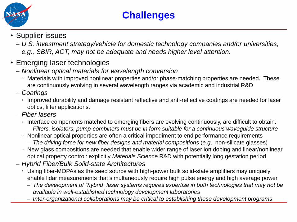
Challenges
• Supplier issues U.S. investment strategy/vehicle for domestic technology companies and/or universities,
e.g., SBIR, ACT, may not be adequate and needs higher level attention.
• Emerging laser technologies Nonlinear optical materials for wavelength conversion
◦ Materials with improved nonlinear properties and/or phase-matching properties are needed. These
are continuously evolving in several wavelength ranges via academic and industrial R&D
Coatings◦ Improved durability and damage resistant reflective and anti-reflective coatings are needed for laser
optics, filter applications.
Fiber lasers◦ Interface components matched to emerging fibers are evolving continuously, are difficult to obtain.
Filters, isolators, pump-combiners must be in form suitable for a continuous waveguide structure
◦ Nonlinear optical properties are often a critical impediment to end performance requirements
The driving force for new fiber designs and material compositions (e.g., non-silicate glasses)
◦ New glass compositions are needed that enable wider range of laser ion doping and linear/nonlinear
optical property control: explicitly Materials Science R&D with potentially long gestation period
Hybrid Fiber/Bulk Solid-state Architectures◦ Using fiber-MOPAs as the seed source with high-power bulk solid-state amplifiers may uniquely
enable lidar measurements that simultaneously require high pulse energy and high average power
The development of “hybrid” laser systems requires expertise in both technologies that may not be
available in well-established technology development laboratories
Inter-organizational collaborations may be critical to establishing these development programs

Challenges
• Slower than expected technology maturation
Achieving SWaP goals
◦ An asymptotic process often characterized by incremental improvements
Achieving reliability goals
◦ An asymptotic process often characterized by incremental improvements
New technology insertion
◦ Are there situations where abandoning a long development path is appropriate?

Technology Needs Charts
• Following charts are not comprehensive recapitulation of 2006 Transmitter
Technologies
Tables enumerate technology categories and high-level status
For comprehensive status update see Final Report

2007 Decadal Survey Needs: 1 m Solid-State Laser
Transmitters
Measure-
ment(s)Technology State of the Art Requirements Development Need
Topography,
aerosol and T
profiles
Pulse Rate 500 Hz,
Solid-state Laser
1 micron, 0.25 J @ 150
Hz PRF, WPE ~ 10%, 1 MHz
linewidth, M2 < 1.51
1 micron, 0.5 J @ 50 Hz
PRF, WPE 6%, 1 MHz
linewidth, M2 < 1.5
Reliability, packaging,
space qualification
Topography,
aerosol and T
profiles
Pulse Rate 1 kHz,
Solid-state Laser
1 micron: 1) bulk, 0.8 J @
5 kHz PRF, WPE ~ 6%2; 2)
fiber, > 1-4 mJ @ 10 kHz,
WPE > 15%, GHz linewidth,
M2 < 1.53
1 micron, 100’s J @
2.5 kHz PRF, WPE 6%,
1-MHz linewidth, M2 < 1.5
Reliability, packaging,
space qualification
Gravity cw Solid-state Single
Frequency Laser
1 micron, ~ 15 kW, WPE ~
10%, ~100 kHz linewidth, M2 <
1.54
1 micron, 20 mW, sub-Hz
linewidth5 (?)
Grace FO focused on
frequency reference. MO
(incl. ) and details of
locking scheme still in flux.
Atmospheric
Composition,
DWL, ocean
mixing-layer
Frequency Conversion see “Fixed Wavelength
Conversion” and “Tunable
Wavelength Conversion”
charts
Harmonic generation of
532, 355 nm; parametric
generation to fixed and
tunable ’s VIS-MWIR
Improved nonlinear optical
materials and anti-
reflective coatings
Topography,
aerosol and T,
oceanography
Fiber/Hybrid
(bulk+fiber)
10-100+ W at 1 m (typically <
1 mJ), PRF 20-100+ kHz, M2 ~
1, WPE 20%
1, 1.5, 2 m, 0.1-few mJ
@ 2.5 kHz PRF, WPE
15%, range of linewidths,
M2 < 1.5
Fiber-integrated
components, low-
nonlinearity gain fiber,
higher WPE pump diodes
High resolution
aerosol, H2O(v),
oceanography
Single signal laser
diodes, amplifiers
10 kHz-few MHz linewidth, 20-
100 mW Pave
linewidth from kHz to MHz
at variety of in VIS-SWIR
range
Linewidth in ~ 10 kHz
range, wavelengths >
telecom
Red font indicates “Emerging Technology”

2007 Decadal Survey Needs: 1.5, 2 m Solid-State
Laser TransmittersMeasure-
ment(s)Technology State of the Art Requirements
Development
Need
CO2,
Coherent
DWL
(aerosol)
Pulsed 2 m,
1.57 m laser
CO2: 30% conversion to
1530-1625 nm via DFG w/
1064 nm fiber-MOPA at
high PRF. DWL: 2 m
Tm/Ho system under
development at LaRC6, >
1J @ ~ 200 ns.
CO2: Pulsed 1.57 m sources w/
Pave ~ 5-20+ W, ~ 10 kHz PRF, ~
1 s pulsewidth, tunable.
DWL: Pulsed 2 m source @ 5-
300 Hz @ EPulse SQRT(PRF) >
0.6 JHz1/2, 8-GHz tunable
frequency-agility, M2 < 1.2, WPE >
5%.
CO2: technology
reliability and
maturation, SWaP
optimization. DWL:
technology reliability
and maturation, SWaP
optimization.
CO2 cw 1.57 and 2
m laser
Literature review in
progress (see Final
Report)
3-5 W cw @ 2.05 microns,
linewidth <50 kHz, 1-GHz tunable,
stabilization to < MHz, FM/IM
capability; 10% WPE. 10 W 1.57
m tunable cw sources.
IM/FM waveform
generation and control,
technology maturation
CH4 Pulsed ~1.65
m laser
Few mJ, kHz Er:YAG, <
10% WPE, uses NPRO
injection seed7
10 mJ/pulse, 1-3 kHz PRF, 10’s of
ns pulsewidth @ 1645 nm,
tunable for DIAL
Q-switched oscillator,
amplifier, WPE, SWaP
CO2, CH4 Fiber/Hybrid
(bulk+fiber)
In active development,
work to date focused on
high PRF
~ 10 W Pave, kHz PRF, ~ 1 s
pulsewidth or cw, tunable at
selected
Integration of fiber-
MOPA w/ bulk
amplifiers; < 20 kHz
PRF (Q-cw pumping of
fiber amps) or cw
CO2, CH4 Single signal
laser diodes
10 kHz-few MHz linewidth,
< few mW Pave
linewidth from kHz to MHz for
DIAL tunable wavelength
converters
Maturation of materials
and designs for 1.6 –
2+ m devices
Red font indicates “Emerging Technology”

2007 Decadal Survey Needs: Fixed Wavelength
Conversion Transmitters
Measure-
ment(s)Technology State of the Art Requirements Development Need
Aerosol, H2O(v),
T,
oceanography
(at 532 nm w/
less penetration
than ~450-480
nm)
Second Harmonic
Generation
~ 70% 1064nm 532 nm
( 24 W @ 150 Hz, Ppk =
16 MW)1; 50%, 1064nm
532 nm ( 200 W)
> 100 mJ @ 532 nm, 10-
200 Hz PRF; 2-5 mJ @
532 nm, 2.5-20 kHz PRF
Incremental
performance and
reliability improvements
O2 Second Harmonic
Generation
> 50% 1530nm765nm 1 J, 10 Hz. Scale telecom
technology lasers to
much higher energy
DWL; aerosol
and T profiles
Third Harmonic
Generation
~ 6 W, 50% 1064+532
355 nm (20 kHz, Ppk ~ 1
MW); ~ 20+% at 150-300
Hz PRF
~ 6 W, 30% 1064+532
355 nm (200 Hz, Ppk ~
10 MW
High efficiency, high
reliability UV generation
None specified Fourth Harmonic
Generation
~ 20% 1064 532266
nm (~ 10 W @ 20 kHz, Ppk
= 0.25 MW)
< 10 Hz and > kHz
systems 1-20 W range (in
reference to O3 meas)
High efficiency, high
reliability UV generation

2007 Decadal Survey Needs: Tunable Wavelength
Conversion Transmitters
Measure-
ment(s)Technology State of the Art Requirements
Development
Need
H2O(v),
oceanography
OPO (vis-nir) ~ 17% conversion to ~ 450 nm
via OPO+sum frequency w/
1064 nm fundamental.10 532
nm pumped OPO/DFG for 700-
1000 nm should be similar
On/off resonance H2O(v)
NIR lines (720, 820, 940
nm); Optimized for
ocean water transmission
400-480 nm
High efficiency,
high reliability VIS-
NIR generation
GHG OPO
(SW/MWIR)
30% conversion of 1 m laser
to 1530-1625 nm via DFG w/
1064 nm fiber-MOPA at high
PRF.11
Tunable source 1570-1650
nm for GHG DIAL, ~ 10 mJ
@ kHz PRF
Average and peak
power scaling,
operation at PRF <
10 kHz, extension
to > 1625 nm
O3, Cascaded
Parametric
(UV-VIS, NIR)
Literature review in progress,
similar to Fourth Harmonic
Generation + sum frequency to
reach 290-320 nm
< 10 Hz and > kHz systems
1-20 W range to support
290-320 nm tunable
systems
High efficiency,
high reliability UV
generation
GHG DFG/OPA
(SW/MWIR)
> 10% DFG to 3-3.8 m range
demonstrated at high PRF
using PPLN+1064 nm fiber
MOPA
Tunable source 3-3.3 m
for CH4 DIAL
Average and peak
power scaling,
operation at PRF <
10 kHz
Red font indicates “Emerging Technology”

Technology Needs Summary
UV
355-400 nm
VIS
400-650 nm
NIR/SWIR
700-2000 nm
MWIR
3-5 micron
Measurement3D Winds;
Water vapor;
Trop. ozone
Physical/biological
oceanography;
aerosols; topography
3D Winds; GHG; water
vapor; O2; topography;
aerosols
GHG (CH4)
Transmitter
THG, OPO/OPA of 1-
m sources; multi-
stage non-linear
wavelength
conversion
SHG of 1-µm sources;
multi-stage non-linear
wavelength conversion
1, 1.5, 1.8-2.6 m
sources; SHG of 1.5, 2
m sources; OPO/OPA
of 1 m sources
OPO/OPA of 1, 1.5,
2 m sources;
narrow-gap laser
diodes
Detector
GaN, MCP, DD-CCD;
Low-noise multi-
element arrays, QE >
50% @ 355 nm
Si-APD, PMT;
Gateable <50 ns, QE 50-
70% @ 450/532 nm
Lm HgCdTe APD;
Gm InGaAs APD;
PMT (to 1.4 m)
MCP (to ~ 900 nm)
Lm HgCdTe APD
HgCdTe FPAs
SL/nBn FPAs
Aperture>1.5-m aperture;
areal density <25 kg/m2 >1.5-m aperture;
areal density <25 kg/m2
>1.5 m aperture;
areal density <25 kg/m2
>1.5-m aperture;
areal density <25
kg/m2
IT*
Sub-µm HPC hardware
and tools;
intelligent sensor
management for laser
life optimization
Sub-µm HPC hardware
and tools;
intelligent sensor
management for laser life
optimization
Sub-µm HPC hardware
and tools;
intelligent sensor
management for laser life
optimization
Sub-µm HPC
hardware and tools;
intelligent sensor
management for
laser life
optimization
* Cross-cutting across multiple measurements and sensor modalities.

Preliminary Conclusions and Recommendations
Conclusions
• 1 m bulk solid-state (BSS) laser technology and associated harmonic
generations to VIS/UV are fairly mature– Development needed for reliability, continuous improvement of WPE of base laser
technology
– Development specifically needed durability and reliability of UV harmonic generation
(wavelengths < 400 nm).◦ NLO materials and crystal coatings are improvement areas
• 1 m fiber-laser technology is rapidly approaching BSS laser technology for Pave
and linewidth performance, lags in Ppk and low PRF parameters. Harmonic
generations to VIS/UV are fairly mature.– Waveform agility a priority for a range of national security lidar applications, development
of waveform generation infrastructure progressing to relatively advanced stage
– Fiber technology development needed to scale peak power capability at 1 m◦ Large mode area fiber and new glass compositions will be key

Preliminary Conclusions and Recommendations
Conclusions
• Telecom-type single-mode laser diodes and optical amplifiers are well-established
at 1480-1625 nm and ~ 1000 nm (Nd3+, Yb3+); emerging in 1625-2000+ nm
range– Continued Development needed for reliability, improvement of WPE for established ranges
– 1625-2000+ nm signal lasers currently have low power, optical amplifiers lacking or at early
stage of development.
• 1.5 and 2 m BSS and fiber-laser technology is in varying stages of development.– High power fiber-MOPA performance in Tm-fiber rapidly advancing
◦ Large mode area fiber and new glass compositions will be key, led by technology start-ups
◦ 793 nm pump diode technology fairly mature, longer pumps in development
◦ Signal diodes and semiconductor amplifiers relatively immature
– High power fiber-MOPA performance in Er-fiber lags◦ Product base strongly oriented to telecom performance requirements. Large mode area and PM fibers
not nearly as widely available as in Yb-fiber
◦ Pump diodes on the order of 30-35% electrical efficiency

Preliminary Conclusions and Recommendations
Recommendations
• Photonic Integrated Circuits (PIC’s) represent opportunity to consolidate signal generation,
amplification, frequency/waveform formatting with significant SWaP improvements– Development of monolithic and heterogeneous Integrated Photonic modules is well established in
1550 nm telecom band, emerging at 1000 nm and 1800-2000+ nm
• Pump diode development needs to continue for improved electrical efficiency and reliability
in 790-1000 nm range, especially at wavelengths needed for direct-pumping Er, Tm, Ho.
• Investigate fiber/BSS hybrid technologies. Potential solutions to difficult performance and
wavelength requirements– At high PRF fiber-based MO+preamp subsystems or fiber-MOPAs enable significant SWaP benefits
and potentially unprecedented waveform agility◦ Especially true for 1020-1100 nm, 1500-1600 nm, 1800-2100 nm wavelength ranges
◦ Development of new glass hosts and new fiber designs should continue
– At lower PRF (< 10 kHz) fiber-based systems/subsystems probably require development for QCW-
pumping and ASE/nonlinear penalty control and mitigation
• Although good nonlinear optical (NLO) materials are available for many measurements
requiring harmonic and parametric wavelength conversion, NLO materials for 200-400 nm
and 1600-2700 nm ranges can be improved– AR coatings and NLO crystals suffer from environmental and damage susceptibilities, and continued
development is needed
– Quasi phase-matched material development in lithium niobate, lithium tantalite, GaAs should continue
for power scaling, efficiency optimization, robustness

Questions & Comments

Backup

Performance Needs References
1. M. Albert et al., Proc. of SPIE Vol. 9612 961209-1
2. R. St Pierre et al., SSDLTR2006/2007
3. Christopher D. Brooks, Fabio Di Teodoro; Opt Exp 13:8999-9002 (2005); ibid, App
Phys Lett 89: (2006)
4. S. Redmond et al., CLEO 2007
5. W. M. Folkner et al., “Laser Frequency Stabilization for GRACE-2”, Proc. ESTF 2011.
6. J. Yu et al., Opt Lett 31:462-464 (2006)
7. D. Chen et al., Opt Lett 34:1501-1503 (2009); D. Chen et al. Opt Lett 36:1197-1200
(2011)
8. M. Kukla et al., Trends in Optics and Photonics 50:484-486, C. Marshall, ed. Optical
Society of America (2001), W. Lotshaw et al., CLEO Technical Digest, Post-deadline
Paper CPD33 (1997); A. Liu et al., Opt Lett 30:67-69 (2005)
9. X. Mu et al., Photonics West, 2016
10. C. Willis et al., Proc. SPIE 9612: 961201 (2015)
11. P. Belden et al., Opt Lett 40:958-961, (2015)

NASA ESTO Lidar Technology Community ForumFebruary 24, 2016
EST/PST:
11:00/08:00 Welcome/Overview of ESTO Investment Strategy Update (A. Valinia, NASA/ESTO)
11:30/08:30 Transmitters State-of-the-Art and Future Requirements (W. Lotshaw, Aerospace)
12:30/09:30 Data Utilization and Acquisition Future Requirements (L. Pearson, Aerospace)
13:15/10:15 Break
13:30/10:30 Receivers State-of-the-Art and Future Requirements (K. Gaab, Aerospace)
14:30/11:30 Emerging Technologies and Trends (D. Tratt, Aerospace)
15:15/12:15 Additional Input from Workshop Participants (All)
16:00/13:00 Adjourn
NASA ESTO Lidar Technology Status
Evaluation:
Data Acquisition & Data Utilization
(Command & Data Handling) Technology
Assessment

• Summary of information technology needs assessment for measurements from the
2007 decadal survey
– Topography (LIST), Winds (3D Wind Demo), CO2 (ASCENDS), Gravity (GRACE II),
Aerosols (ACE)
• Summary of information technology needs for new measurement concepts
– Biomass, phytoplankton, ocean mixed layer depth, non-CO2 GHG, other atmospheric
composition
• Overview of information technology development needs
– Onboard processing
– Spacecraft control and communication
– Ground processing
– Algorithms/models
• Overview of emerging information technology trends
• Recommendations
• Q&A
Contents

C&DH Assessment for 2007 Decadal Survey
Measurement Recommendations
Capability Gap Measurements TRL
Cloud detection, instrument pointing (<4 µrad),
health monitoring
CO2 (ASCENDS) 4
Instrument pointing knowledge, compression Aerosol (ACE) 4
None (met by GEDI) 3D Biomass (DESDynI) 6
None (met by GRACE FO, Sat-to-Sat
communication)
Gravity (GRACE II) 6
Onboard processing, compression, laser life
prognosis (<days)
Topography (LIST) 3
Autonomous acquisition, real-time LOS wind,
validation (<1hr), OSSE
3D Winds (Demo) 5

Enabling Technologies for New Concepts
Capability Concept TRL Challenge
Cross-cutting 3D biomass 3 Onboard compression,
calibration & validation
Algorithm Phytoplankton 4 Event detection
Algorithm Ocean mixed layer depth 5 Cloud detection
Technology Non-CO2 GHG 5 Instrument pointing
Health & Monitoring Atmospheric composition 4 Instrument pointing, laser
life prognosis

General Observations
• Four categories of development needs
– Technology
– Engineering
– Cross-cutting
– Algorithms
• Engineering needs are mission specific based on instrument, power, and spacecraft
– It is not feasible to start the development until phase A
• Cross-cutting needs require long term investment and standardization
– Onboard processor and storage
– Instrument interface, telecommunication, data compression
– Ground data processing, data analytics
• Algorithms
– Instrument specific
– Model-specific data
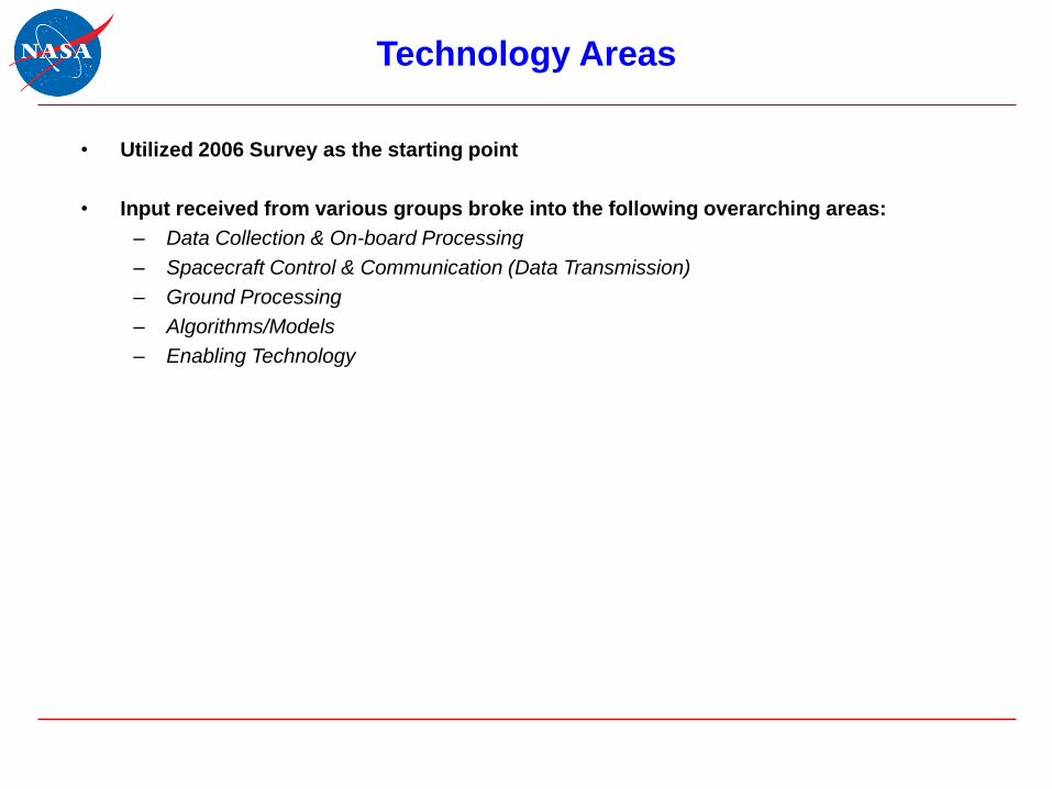
Technology Areas
• Utilized 2006 Survey as the starting point
• Input received from various groups broke into the following overarching areas:
– Data Collection & On-board Processing
– Spacecraft Control & Communication (Data Transmission)
– Ground Processing
– Algorithms/Models
– Enabling Technology

Onboard Processing
• Optimize data collection
• Effort is to reduce the amount of data initially collected, i.e., don’t simply operate
sensor in always-on mode. Use information from a variety of sources to do this,
thereby reducing resource impacts downstream.
• Adaptive Sensor Operations: with knowledge from another platform, another on-
board sensor, the data from the active sensor or a pre-loaded dataset,
automatically reconfigure the sensor collection parameters to collect the right data
or the right target
– On-board Sensor Control
– Standardization of Interfaces and Controls
– Spacecraft Area Network
– Formation Flying
• Science model-driven adaptive targeting

Onboard Processing (Cont.)
• Even with the effort to reduce the amount of data collected, data volumes are expected to
continue to increase. Need to store, process, and compress it on-board to meet various
mission needs.
• On-board Storage
– Space-qualified Terabyte storage Hardware
• On-board Processing
– Space-qualified HPC HW & programming tools
– On-board near real-time data processing
– Real-Time wind profiles
– Mission error Budgets
• Software Compressive Sensing
• On-Board Data Compression
• Development of compression algorithms to reduce the amount of data retained and
transmitted. Development of “policy” on the use of lossy compression – is it ever
acceptable not to transmit/archive the original data?
• Space-qualified HPC HW & programming tools
• Data Compression: Lossless
• Data Compression: Lossy

• Health Monitoring & Control
• Need both autonomous on-board sensor health monitoring & correcting capabilities,
combined with the use of “ground truth” data from both airborne and ground-based
lidar systems for calibration and data validation.
• Intelligent sensor health & safety
• Airborne lidar validation systems
• Ground lidar validation systems
• Pointing & tracking
Onboard Processing (Cont.)

Spacecraft Control and Communication
• Transmit (& Receive) the Data
• A platform/sensor can be expected to transmit data to another on-board sensor, to
another satellite or to the ground. Standards and protocols need to be established to
facilitate. Quantity of data is continuing to increase, advanced data transmission
capabilities need to be developed (i.e., laser communications). A platform can also be
either producer or consumer of this satellite-to-satellite data.
• Transmit the data to another Sensor
– Standardization of Interfaces & Protocols
• Transmit the data to another Satellite
– Standardization of Interfaces & Protocols
• Transmit the data to Ground
– Large Volume Data Downlink: Laser Communications

Ground Processing
• Ground Systems
• Once the data has been transmitted to the ground, it must support various levels of
processing: near real-time Decision Support Applications, Science Products and
further science research.
– Knowledge Discovery
– Cloud-based Processing
• Establish cloud-based service oriented architecture for processing data once it
reaches the ground allows for rapid expansion and contraction of capacity
eliminating the need to maintain large local processing clusters for each mission.
– Storage & Archive
• Data Management/Service Oriented Architecture
• Cloud-based Storage: Establishing cloud-based storage capability will allow
cloud-based data holdings to be published to a variety of architectures as a
service. Raw data can be archived to offline storage, while processed (more
actively used data/products) can be maintained online for faster access.

Ground Processing (Cont.)
• Data Dissemination
• Data delivery should be flexible enough to provide the requestor with the exact data
and metadata needed, in the format needed. Additionally, the ability to provide online
visualization of data should be a part of the concept of operations, if the data content
allows.
• Data Compression: Lossless
• Data Compression: Lossy
• Data Visualization

Algorithms/Models
• This is not a technology development. Most of the development needs should be
addressed by mission and ROSES R&A
• Modeling
– Observation System Simulation Experiments (OSSE)
– Model lidar data resampling techniques
• Algorithms
– Instrument specific algorithms and theories
– Ancillary data processing
– Calibration and validation campaigns

Enabling Technologies
• Cloud detection – optimization of compute intensive processing
• Coordinate sensing and event detection – onboard real-time data architecture
• Onboard processing and storage – space qualification of device technology
• Laser life prognosis – laser characterization, interactive sensing based on event
detection

Emerging Technology Trends
• FPGA
– IBM Coherent Accelerator Processor Interface (CAPI), PCIe
– Xilinx Virtex-5QV; Microsemi RTG4; Xilinx Zynq (non-rad-hard processor plus FPGA)
Future Interface technologies; JEDEC JEDS204B high-speed serial interface
ADC/DAC converters.
• MEMEX
– Grobid (GeneRation Of BIbliographic Data machine learning framework)
– Apache Tika (detects and extracts metadata and text from over various file formats)
– NLTK (natural language toolkit)
• CARACAS – onboard Control Architecture for Robotic Agent Command and Sensing
• Observations for model intercomparison projects (obs4MIPs)
• Cloud computing and network

C&DH Capability Advancement Recommendations
• Establish testbed in order to test onboard capabilities
• Cross-cutting needs
– Address instrument specific interfaces and requirements
• Quantitative goals are needed to address Instrument specific compression and
innovative retrieval algorithms
– Free flyer vs. hosted payload, processing power, platform specific
• Establish calibration and validation sensor network for remote sensing instruments
• Sample/synthetic data needed to test processing algorithms
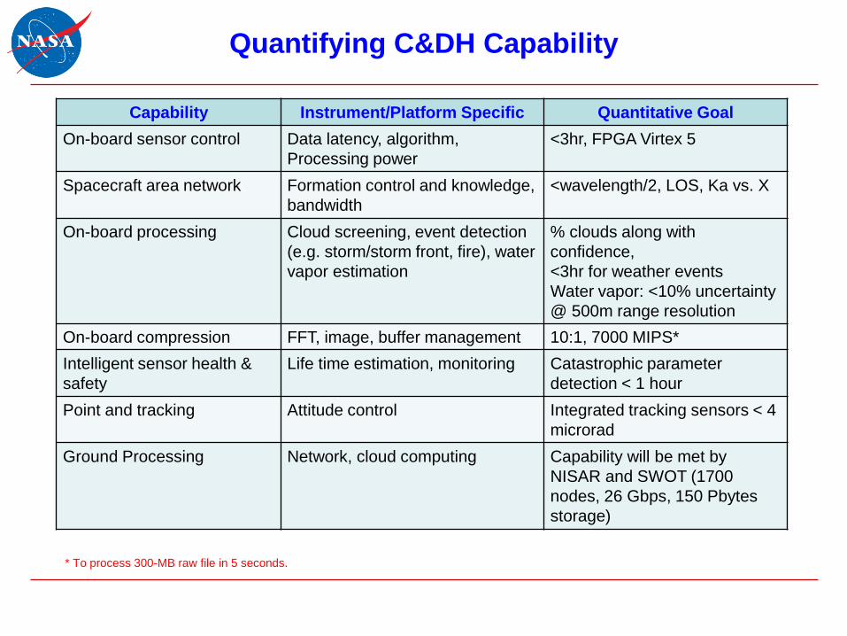
Quantifying C&DH Capability
Capability Instrument/Platform Specific Quantitative Goal
On-board sensor control Data latency, algorithm,
Processing power
<3hr, FPGA Virtex 5
Spacecraft area network Formation control and knowledge,
bandwidth
<wavelength/2, LOS, Ka vs. X
On-board processing Cloud screening, event detection
(e.g. storm/storm front, fire), water
vapor estimation
% clouds along with
confidence,
<3hr for weather events
Water vapor: <10% uncertainty
@ 500m range resolution
On-board compression FFT, image, buffer management 10:1, 7000 MIPS*
Intelligent sensor health &
safety
Life time estimation, monitoring Catastrophic parameter
detection < 1 hour
Point and tracking Attitude control Integrated tracking sensors < 4
microrad
Ground Processing Network, cloud computing Capability will be met by
NISAR and SWOT (1700
nodes, 26 Gbps, 150 Pbytes
storage)
* To process 300-MB raw file in 5 seconds.

• Measurement requirements must be clearly defined.
• Quantitative requirements then follow
• Technology requirements for each measurement in the areas of transmitters, receiver
systems, and DADU/C&DH are tightly coupled.
• Subsystems are not implementable if top-down requirements are not defined in terms of
mass, power, volume, interface, mechanical/thermal, data rate, and mission life
• Technology development to satisfy the priority measurement(s) must then be targeted
and coordinated in the three categories in order to achieve maximum return on
investment.
Preliminary Conclusions and Recommendations

Questions & Comments

Sample from the Inputs
Yellow: Technology
Green: Engineering
Blue: Cross-cutting development needs

NASA ESTO Lidar Technology Community ForumFebruary 24, 2016
EST/PST:
11:00/08:00 Welcome/Overview of ESTO Investment Strategy Update (A. Valinia, NASA/ESTO)
11:30/08:30 Transmitters State-of-the-Art and Future Requirements (W. Lotshaw, Aerospace)
12:30/09:30 Data Utilization and Acquisition Future Requirements (L. Pearson, Aerospace)
13:15/10:15 Break
13:30/10:30 Receivers State-of-the-Art and Future Requirements (K. Gaab, Aerospace)
14:30/11:30 Emerging Technologies and Trends (D. Tratt, Aerospace)
15:15/12:15 Additional Input from Workshop Participants (All)
16:00/13:00 Adjourn
NASA ESTO Lidar Technology Status
Evaluation
Receiver Technologies Assessment

Contents
• Summary of receiver technology assessment for measurements from the 2007
decadal survey
– Topography (LIST), Winds (3D Wind Demo), CO2 (ASCENDS), Gravity (GRACE II),
Aerosols (ACE)
• Summary of receiver technology needs for new measurement concepts
– 3D biomass, phytoplankton, ocean mixed layer depth, non-CO2 GHG, other
atmospheric composition
• Overview of technology vs engineering development needs
• Overview of emerging technology trends
• Recommendations
• Q&A

Receiver Assessment for the 2007 Decadal Survey
Measurements
Capability Gap Measurements TRL“Greatest
Challenge” TRL
High-efficiency detectors
in 1.5-2 micron rangeCO2 (ASCENDS) 5
Space
qualification/radha
rd assurance
Field-widened
interferometric receiverAerosol/Clouds/Ecosystems (ACE) 4 Wavefront error
High-bandwidth, high-
sensitivity detector
arrays
3D Biomass (NISAR/GEDI, formerly
DESDynI)5 N/A
None Gravity (GRACE II) 6 N/A
Multiple aperture/beam
receiverTopography (LIST in 2007 Decadal) 3
Large-area
detector with high
readout b/w
Single telescope
supporting multiple look
angles
3D Winds 3
Large-aperture
receive optics
(HOE/DOE,
interferometer)

Enabling Technologies for New Measurement Concepts
Capability Gap Concept TRL “Greatest
Challenge” TRL
Detector performance Phytoplankton 2 Dead-time,
afterpulsing
Detector performance Ocean Mixed Layer 2 Dead-time,
afterpulsing
Low-noise, few-photon-sensitive
detector array
Non-CO2 Green House Gases 5 Space qualification
Large-aperture collector; detector
efficiency
Ozone 4 Deployability
Detector performance Water vapor profiles 4 Low-noise, photon-
sensitive detector
array

Background
• The 2006 report contained 9 technology areas:
– Alignment Maintenance
– Scanning Systems
– Large Effective Area, Light-weight Telescopes
– Mechanical Metering (e.g., thermally stable, lightweight optical bench, trusses)
– Specialty Optics (e.g., high transmission optics, fibers, polarization)
– Narrowband Optical Filters
– Detectors and Amplifiers
– Optical High Resolution Spectral Analyzers
– Detection Electronics (e.g., high-speed ADC, multi-channel scaler)
• Areas changed in 2016 report
– Added Cryocoolers
• Compact, low power cryocoolers critical for infrared detectors
– Removed Mechanical Metering
• Quantitative requirements not reported
• Recognized as a key part of system design and can be used to relax active alignment and focus
control requirements in systems (e.g., SiC structure and optics in ADM-Aeolus ALADIN)

Technology Areas 2016
Technical Area 2006 2016 Rationale
Alignment Maintenance X X Cross-cutting technology.
Scanning Systems X XCross-cutting technology for measurements requiring
multiple look angles or specific look angles on command
Large Effective Area,
Light-weight TelescopesX X Cross-cutting technology for virtually all measurements
Mechanical Metering X - No quantitative requirements were levied
Specialty Optics X X Cross-cutting component
Narrowband Optical
FiltersX X Core technology for each measurement
Detectors and Amplifiers X X Core technology for each measurement
Optical High Resolution
Spectral AnalyzersX X Needed for HSRL systems to ocean profiling, aerosol
Detection Electronics X X Cross-cutting technology
Cryocoolers - XRequired for low-noise, high QE detectors in the
NIR/SWIR/MWIR (e.g., HgCdTe Lm-APD)

Observations
• Alignment maintenance is generally still challenging at the ~5-10 µrad regime, but
significant improvements have been made in the past 10 years
– ICESat-2 ATLAS will meet 2006 requirement for altimeters when launched
– Has not been demonstrated for smallsats
– Implementation at this level is primarily an engineering challenge and not a technology
development effort, with the exception of a few areas (i.e., lag-angle compensation, SWIR)
• Cross-cutting technology: large, light-weight apertures
– Power-aperture product: larger apertures or higher power lasers (or both)
– Current SOA space-based telescopes are 1-2 m diameter
– Lighter-weight, cost-effective apertures in the 1-2 m range would improve system SWaP
trades (additive manufacture)
– Deployable apertures larger that >1.5-2 m would enable reduced laser power or improve
system performance
– Smaller deployable apertures could enable some missions from smallsats

Observations (cont.)
• All measurement scenarios would benefit from improved detector performance
– Multi-element detectors with high QE/PDE, low noise, low timing jitter
– Full-waveform capabilities and large dynamic range (single-photon to high count rates)
– For cooled arrays, higher operating temp and/or improved cryocoolers needed
• State-of-the-art Dewar-cooler technologies, particularly linear-drive technology, are getting as
small as 5x5x5 cm and power consumption of a few watts.
• MEMS-based coolers are under development
– Strong belief that domestic industry base is not currently able to respond to lidar
community needs for affordable, low-volume, custom detector designs
– International collaboration on custom detectors challenging due to ITAR/EAR restrictions
• Cross cutting: additive manufacturing for improved mechanical and thermal stability,
reduced size and weight
• As in the case of transmitters, opportunities for synergistic DoD contractor development

Technology Needs: Alignment
NASA ESTO Lidar Community Workshop 24Feb16
Measurement Technology State of the Art Requirements Development Need
Wind
Voice-coil
actuated 2-axis
beam control
with reference
camera star-
tracker and
INS system
5-10 µrad co-alignment
demonstrated in the
Vis/NIR for ground and
airborne systems. ~5
µrad will be
demonstrated in a
satellite system on
ATLAS with LRS.
Lag-Angle
Compensation: Still
being evaluated;
designs for ~1 µrad
LAC developed, 10s of
µrad demonstrated
5 microrad roundtrip (5
msec) lag angle
compensation
(coherent)
50 microrad active T/R
boresite alignment
(direct)
• Develop optical lag angle
compensator
• Prelaunch lidar alignment
subsystem; highly quality
beam reducing telescope; >
50 cm diameter for space
application for far-field
• On-orbit pointing knowledge
subsystem (alignment
sensor+INS) needs to be
demonstrated at 2 micron.
Needs high-efficiency, high-
sensitivity SWIR star tracker,
high temp (TEC or room
temp.)
• Develop active optical
boresite alignment device
CO2
50 microradian standard
deviation on a zero
mean
Maintain
transmit/receive overlap
on the signal detector(s)
to within 10% of ideal
On-orbit pointing knowledge
subsystem (alignment
sensor+INS) needs to be
demonstrated at 2 micron.
Needs high-efficiency, high-
sensitivity SWIR star tracker,
high temp (TEC or room temp.)

Technology Needs: Scanning Systems
Measurement Technology State of the Art Requirements Development Need
Wind Still under review
TWiLiTE telescope uses a
40 cm diameter HOE as
the receiver collecting and
focusing aperture
30 deg nadir angle wide
field of view telescope
designs
Develop >75 cm
holographic or
diffractive optic
telescope and step
stare rotating
mechanism including
momentum
compensation.
Topography
Polarization
Gratings (cycloidal
diffractive
waveplates)
and/or
SEEOR (LC-clad
waveguide)
Switchable fiber
arrays
SEEOR: Vis-NIR
operation, 60x15 degree
FOV 2D scan
GFSC has demonstrated
benchtop fiber array for
FOV selection
addressable FOV across
1 - 2 degrees
Develop solid-state
approach of selecting
individual fields-of-view
at high switching rates.
Wind,
Topography, T
and Water
Still under review
10 cm devices with
acceptable efficiencies
have recently been
demonstrated.
Non-mechanical large
aperture (> 25 cm)
beam steering and
receiver pointing
devices.

Technology Needs: Telescopes
Measurement Technology State of the Art RequirementsDevelopment
Need
Wind, Aerosols
Beryllium or SiC
Field lens-corrected
Ritchey-Chretien or
other Cassegrain
receive telescope
Single aperture, 1-1.5 m,
~0.2-0.5 mrad FOV
Light-weight telescopes > 1
m
Light-weight,
deployable
telescopes > 2 m
diameter*
Aerosol, Ocean,
Non-CO2,
Phytoplankton
2-5 meter primary mirror
telescope for space based
lidar, <F/1 primary, <100
micron blur circle, high
transmission (>95%) at
target wavelength(s), low
thermal distortion, high
rigidity
Topography1 - 1.5 m diameter, < 10
microradian blur circle
CO2, Ozone
3m diameter deployable,
~100 mrad FOV, areal
density <25 Kg/m2
* Aperture size requirement is dependent on transmitter.

Technology Needs: Specialty Optics
Measurement Technology State of the Art RequirementsDevelopment
Need
Wind
Pure silica
or
Hollow-core
photonic crystal
fiber
Commercially available
options, but may not meet
requirements in both UV
and Vis, may not be space
qualified
Fiber couplers and fiber
optics with high
performance at 355 and
532, rad hardened
Improve UV rad-hard
fiber couplers and fiber
optics
Phytoplankton,
aerosol, ocean
mixed layer
Hard coated rugate
or other interference
filter
Meets or exceeds
specification except
possibly at UV edge
1-3 nm half-height or
better, D > 5, 90%
transmission or better in
380-800 nm range
Develop the 532 nm
notch filter that meets
or exceeds the
specification
CO2 SiO2/GeO2
PM single mode passive
optical fibers are
commercially available but
are not rad hard, may not
meet transmission
requirements
Polarization maintaining,
radiation tolerant 2
micron single mode fiber
with transmission
efficiency > 95%/m
Assess radiation
hardness and improve
transmission of fibers

Technology Needs: Narrowband Optical Filters
Measurement Technology State of the Art Requirements Development Need
Wind, Aerosol,
Ocean
Quasi-monolithic
field-widened
Michelson or Mach-
Zender interfero-
meters
~1 degree, 25 mm
aperture
0.1-1 m OPDs
Demonstrated 25:1-50:1
transmission ratios with
Michelson design.
Wavefront error limits
contrast
Increase interferometer
to > 10 mrad to support
large telescopes.
0.1-1 m OPDs. GHz
resolution or less, Mie
transmission ratio of
>100:1, goal of 1000:1 to
support HSRL
measurement in clouds
Athermal field-widened
interferometers to
support larger
apertures
CO2
Hard coated oxide
interference filters
Few 100 picometers
FWHM, >80% T, rounded
transmission peak, OD9
out of band rejection
100s of pm, >90% T, flat
top profile
Stable, flat top filters
need to reduce filter
distortion, improve
SNR
Water Still under review Still under review
high transmission
(>80%), fast temporal
response (<100
microseconds), <10-20
pm optical bandpass,
large free spectral range
(>100-300 pm), high
contrast ratio (> 100/
contrast ratio), etendue
>50mm-mrad
Tunable interferometric
filter for
implementation in high
PRF multi-wavelength
DIAL in the VIS-NIR

Technology Needs: Detectors
Measurement Technology State of the Art Requirements Development Need
Wind (direct or
hybrid), Aerosol
PMTs,, Si APD, or
Accumulation CCDs
PMTs, QE ~25%
Si APD, >65% QE, < 300 cps
DCR, < 50 ns dead time
ACCD: 85% QE, 16x16 pixels,
25 x 2.1 us range gates, 7
noise e- per pixel, 16-bit ADC
Single element or array
detectors with single photon
counting sensitivity, QE> 50
%, internal gain 10^6, dark
current <1 kcps, active area >
2 mm2
Develop and demonstrate
photon counting detector
arrays for increased
dynamic range
Wind (coherent)
CO2, non-CO2
GHG, water
HgCdTe APD arrays
80K, 2x8 pixel arrays, 75% QE,
200 kHz DCR, few photon
sensitive, 10 MHz bandwidth,
400-4200 nm responsivity
Multipixel arrays, >75% QE,
<200 kHz DCR, few photon
sensitive, 10 MHz bandwidth,
750-3400 nm responsivity,
low power consumption (<5W
including cooler)
Develop and demonstrate
arrays
Ocean Mixed
LayerSi APD or PMT
PMTs, QE ~25%
Si APD, >65% QE, < 300 cps
DCR, < 50 ns dead time
Gated on and off within 20-50
ns, high quantum efficiency
(>50%, goal >70%), Excess
noise factor <2 (variance
domain), low afterpulsing ,
large dynamic range, large
aperture (>1 mm^2), low dark
noise, Gain 10^5- 10^6
Develop and demonstrate
arrays
Topography, 3D
biomass, Aerosol
Si APD or PMT (532
nm)
InGaAs or HgCdTe APD
(1064 nm)
InGaAs: 256x64 pixel arrays,
35% QE, < 10 kHz DCR, single
photon sensitive, ~350 ps
timing jitter, asynchronous
HgCdTe: 80K, 2x8 pixel arrays,
75% QE, 200 kHz DCR, few
photon sensitive, 10 MHz
bandwidth, 400-4200 nm
responsivity
Large arrays (256x256), high-
efficiency (>50%), high-
bandwidth (1 GHz), low-
timing jitter (<100 ps) arrays
with high count rates (>100
Mcps).
Low-cost, high efficiency,
larger format, radiation
hard photon counting
arrays

Technology Needs: High Resolution
Spectral Analyzers
Measurement Technology State of the Art RequirementsDevelopment
Need
Phytoplankton,
ocean mixed
layer
Still under review
Although there are
commercial prototypes,
none of them meets the
specified quantitative
requirements and is a
space-qualified product.
LSE detection in 520-800
nm (optional: 370-800
nm, TBD) range, 1-3 nm
resolution, adjustable
gating with 40-100 ns
pulses synchronized with
the LSE backscatter
arrivals, photon counting
capability, high quantum
(QE) efficiency (50% or
better), low noise
Develop a space-
qualified LSE spectral
detector/analyzer that
meets or exceed the
listed requirements

Technology Needs: Detection Electronics
Measurement Technology State of the Art Requirements Development Need
Wind Still under review Still under review
FPGA based Real time
processors for LOS winds
from multiple lines of sight
with variable platform
motion
on-board processing of
sensor (e.g. Star tracker
pointing + lidar Doppler
shift) information into
data product (e.g. wind)
estimates
CO2 Still under review Still under review 20 MHz, 16 bit ADCHigh speed, high
resolution ADC
Topography Still under review Still under review
low power(<50W),12 bit, 1
Gsamp/s, 9 channel
digitizer
streaming digitizer, 1
Gsamp/s, 10-12 bit
resolution with integrated
pulse identification and
time tagging
Develop a low power
option for return pulse
digitization with 10-12
bits of dynamic range at
sampling rates of 1
Gsamp/s. Integrated
return-pulse identification
and processing is
desired.
Couple a high-speed A/D
converter with a high-
speed FPGA capable of
continuous digitization
and real-time return-
pulse identification.

Technology Needs Trades
UV
355-400 nm
VIS
400-650 nm
NIR/SWIR
700-2000 nm
MWIR
3-5 micron
Measurement3D Winds;
Water vapor;
Trop. ozone
Physical/biological
oceanography;
aerosols; topography
3D Winds; GHG; water
vapor; O2; topography;
aerosols
GHG (CH4)
Transmitter
THG of 1-m sources;
multi-stage non-linear
wavelength conversion
SHG of 1-µm sources;
multi-stage non-linear
wavelength conversion
1, 1.5, 1.8-2.6 m
sources; SHG of 1.5, 2
m sources; OPO/OPA
of 1 m sources
OPO/OPA of 1, 1.5,
2 m sources;
narrow-gap laser
diodes
Detector
GaN, MCP, DD-CCD;
Low-noise multi-
element arrays, QE >
50% @ 355 nm
Si-APD, PMT;
Gateable <50 ns, QE
50-70% @ 450/532 nm
Lm HgCdTe APD;
Gm InGaAs APD;
PMT (to 1.4 m)
MCP (to ~ 900 nm)
Lm HgCdTe APD
HgCdTe FPAs
SL/nBn FPAs
Aperture>1.5-m aperture;
areal density <25
kg/m2
>1.5-m aperture;
areal density <25 kg/m2
>1.5 m aperture;
areal density <25 kg/m2
>1.5-m aperture;
areal density <25
kg/m2
IT*
Sub-µm HPC hardware
and tools;
intelligent sensor
management for laser
life optimization
Sub-µm HPC hardware
and tools;
intelligent sensor
management for laser life
optimization
Sub-µm HPC hardware
and tools;
intelligent sensor
management for laser life
optimization
Sub-µm HPC
hardware and tools;
intelligent sensor
management for
laser life
optimization
* Cross-cutting across multiple measurements and sensor modalities.
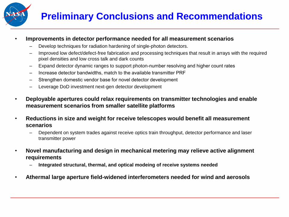
Preliminary Conclusions and Recommendations
• Improvements in detector performance needed for all measurement scenarios
– Develop techniques for radiation hardening of single-photon detectors.
– Improved low defect/defect-free fabrication and processing techniques that result in arrays with the required
pixel densities and low cross talk and dark counts
– Expand detector dynamic ranges to support photon-number resolving and higher count rates
– Increase detector bandwidths, match to the available transmitter PRF
– Strengthen domestic vendor base for novel detector development
– Leverage DoD investment next-gen detector development
• Deployable apertures could relax requirements on transmitter technologies and enable
measurement scenarios from smaller satellite platforms
• Reductions in size and weight for receive telescopes would benefit all measurement
scenarios
– Dependent on system trades against receive optics train throughput, detector performance and laser
transmitter power
• Novel manufacturing and design in mechanical metering may relieve active alignment
requirements
– Integrated structural, thermal, and optical modeing of receive systems needed
• Athermal large aperture field-widened interferometers needed for wind and aerosols

Questions & Comments

NASA ESTO Lidar Technology Community ForumFebruary 24, 2016
EST/PST:
11:00/08:00 Welcome/Overview of ESTO Investment Strategy Update (A. Valinia, NASA/ESTO)
11:30/08:30 Transmitters State-of-the-Art and Future Requirements (W. Lotshaw, Aerospace)
12:30/09:30 Data Utilization and Acquisition Future Requirements (L. Pearson, Aerospace)
13:15/10:15 Break
13:30/10:30 Receivers State-of-the-Art and Future Requirements (K. Gaab, Aerospace)
14:30/11:30 Emerging Technologies and Trends (D. Tratt, Aerospace)
15:15/12:15 Additional Input from Workshop Participants (All)
16:00/13:00 Adjourn

NASA ESTO Lidar Technology Status
Evaluation:
Emerging Technologies Assessment

• Definition of emerging technologies
• Summary of emerging technology needs assessment for measurements from the
2007 decadal survey
– Topography (LIST), Winds (3D Wind Demo), CO2 (ASCENDS), Gravity (GRACE II),
Aerosols (ACE)
• Summary of emerging technology needs for new measurement concepts
– 3D biomass, phytoplankton, ocean mixed layer depth, non-CO2 GHG, other
atmospheric composition
• Overview of emerging technology development needs
– Transmitter technologies
– Receiver technologies
– Information technologies (C&DH)
• Summary and Recommendations
• Q&A
Contents

Laser Remote Sensing
Altimetry, Geodetic Imaging
Direct Detection
Photon Counting
SingleDetector
Geiger Mode
Linear Mode
ArrayDetector
Geiger Mode
Linear Mode
Analog
SingleDetector
Single Pulse
Full Waveform
ArrayDetector
Single Pulse
Full Waveform
Coherent Detection
Real ApertureSynthetic Aperture
Single Detector
ArrayDetector
Other
Speckle Imaging, Pupil
Plane
Fourier Telescopy
Spectral
Multi-Wavelength
DIAL (atmospheric
gases)
Direct Detect Pulsed
IPDA(pulsed, cw)
PRN Waveforms
FM DIAL
Coherent DIAL/IPDA
Other
LIBS
Raman
Fluorescence
Elastic Backscatter
Vibrometry, Acoustics
Atmospheric
Clouds, Aerosols, Dust
Multi-Wavelength
Polarimetric
Winds
Direct
Coherent
Auto-covariance
Temperature Profiles
Rayleigh
Boltzmann
Adapted and updated from: Laser Radar: Progress and Opportunities in Active Electro-Optical Sensing (NRC, 2014).
Laser Remote Sensing Taxonomy: Space
Key:
Space-Proven (TRL 7-9)
Developmental (TRL 4-6)
Experimental (TRL 1-3)
Each sensor/measurement has its own Command and Data Handling ‘shadow’, in addition to the cross-cutting IT challenges.

Laser Remote Sensing
Altimetry, Geodetic Imaging
Direct Detection
Photon Counting
SingleDetector
Geiger Mode
Linear Mode
ArrayDetector
Geiger Mode
Linear Mode
Analog
SingleDetector
Single Pulse
Full Waveform
ArrayDetector
Single Pulse
Full Waveform
Coherent Detection
Real ApertureSynthetic Aperture
Single Detector
ArrayDetector
Other
Speckle Imaging, Pupil
Plane
Fourier Telescopy
Spectral
Multi-Wavelength
DIAL (atmospheric
gases)
Direct Detect Pulsed
IPDA(pulsed, cw)
PRN Waveforms
FM DIAL
Coherent DIAL/IPDA
Other
Raman
Fluorescence
Elastic Backscatter
Vibrometry, Acoustics
Atmospheric
Clouds, Aerosols, Dust
Multi-Wavelength
Polarimetric
Winds
Direct
Coherent
Auto-covariance
Temperature Profiles
Rayleigh
Boltzmann
Laser Remote Sensing Taxonomy: Suborbital
Adapted and updated from: Laser Radar: Progress and Opportunities in Active Electro-Optical Sensing (NRC, 2014).
Key:
Suborbital-Proven (TRL 7-9)
Developmental (TRL 4-6)
Experimental (TRL 1-3)
Each sensor/measurement has its own Command and Data Handling ‘shadow’, in addition to the cross-cutting IT challenges.

Emerging Technology Definitions
• Since the 2006 report there has been a revolution in smallsat/hosted payload concepts, fueled in
part by an increasingly (even aggressively) cost-constrained environment
– In this paradigm miniaturization is key
– The burgeoning additive manufacturing field offers potential solutions for previously impossible enabling
constructs (e.g., large-area mirrors that are lightweighted in ways that cannot be accomplished through other
means)
– Integrated photonics approaches are being used to dramatically compact optical designs
• The decision to actively address this emerging technologies in the 2016 report reflects a
realization that new capabilities could determine the success of more stringent measurement
requirements and that they should be defined and their development accelerated
• “Emerging technologies are technologies that are perceived as capable of changing the status
quo” (Wikipedia)
– Potential game changers
• For the current purpose we defined emerging technologies as being at a maturity level of <TRL3
– TRL 2 is the entry point for ESTO’s ACT and AIST programs
• System engineering as an emerging technology
– Trades between aperture size, detector efficiency, laser power, and waveform can mitigate technological hurdles
– Requires robust, high-fidelity modeling and simulation capabilities

Capability Gap Measurements Current TRL
SWIR optical mux CO2 (ASCENDS) 2
Tunable NIR laser;
High-QE UV/Vis detectors;
Narrowband wide-acceptance filter
Aerosol (ACE) 1-2
Intelligent performance management 3D Biomass (DESDynI) 2-3
Demonstrated by GRACE FO* Gravity (GRACE II) ▬
Intelligent performance management Topography (LIST) 2-3
High-QE multi-element UV/SWIR detector arrays 3D Winds (Demo) 2
Intelligent performance management;
Rad-hard deep-submicron microelectronics All 2-3
Unmet Technology Needs Since Prior Decadal
Survey
* Laser supplied by DLR (Germany).

Capability Measurement Current TRL
Intelligent performance management 3D biomass 2-3
Narrowband blocking filter;
High-resolution spectral analyzerPhytoplankton 2
Moderate PRF blue laser Ocean mixed layer depth 2
SWIR optical mux GHG 2
Tunable NIR laser;
NIR optical mux;
Photonic crystal fiber gas reference cell;
Large collection aperture;
Narrowband wide-acceptance filter
Other atmospheric composition (water
vapor)1-2
Tunable UV laser;
Large collection apertureOther atmospheric composition (ozone) 2
Tunable NIR laser;
High-QE UV/Vis detectors;
Narrowband wide-acceptance filter
Other atmospheric composition (clouds and
aerosols)1-2
Intelligent performance management;
Rad-hard deep-submicron microelectronics All 2-3
Emerging Needs for New Measurement Concepts
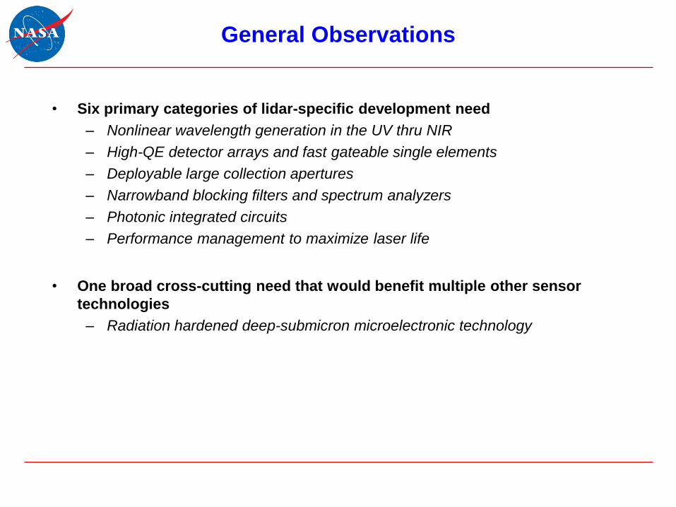
• Six primary categories of lidar-specific development need
– Nonlinear wavelength generation in the UV thru NIR
– High-QE detector arrays and fast gateable single elements
– Deployable large collection apertures
– Narrowband blocking filters and spectrum analyzers
– Photonic integrated circuits
– Performance management to maximize laser life
• One broad cross-cutting need that would benefit multiple other sensor
technologies
– Radiation hardened deep-submicron microelectronic technology
General Observations

Technology
Thrust AreaMeasurement State-of-the-Art Notional Requirements
Blue laser
Ocean
temperature
profiles (mixed
layer depth)
SHG/THG of 940/1320 nm
Nd:YAG; OPO w/Nd:YAG 3rd
harmonic
400-480 nm;
PRF ≤ 500 Hz;
30-100 mJ
UV laserTropospheric
ozone profiles
High-energy pumped multi-
stage cascaded non-linear
optical scheme
UV pairs separated by 10-20
nm;
space: 305-320 nm; airborne:
290-320 nm;
high efficiency, 100-1000 Hz,
20-100 mJ, M2 <2, linewidth <1
Å, pulse width 10-30 ns
NIR laser
Water vapor and
aerosol/cloud
profiles
Current Ti:Sapphire lab solution
not viable for space;
532-nm pumped OPO or
cascaded non-linear optical
scheme with high-WPE 1/1.5-
m pump laser
720 nm, WPE 5-10%, 20-40 W
at 1000-3000 Hz, or 100 mJ at
100 Hz double pulsed within
200-300 microseconds,
spectral purity >5000/1,
pulsewidth <20 ns, linewidth
<100 MHz
Emerging Transmitter Laser Technologies
Technology
Thrust AreaMeasurement State-of-the-Art Notional Requirements
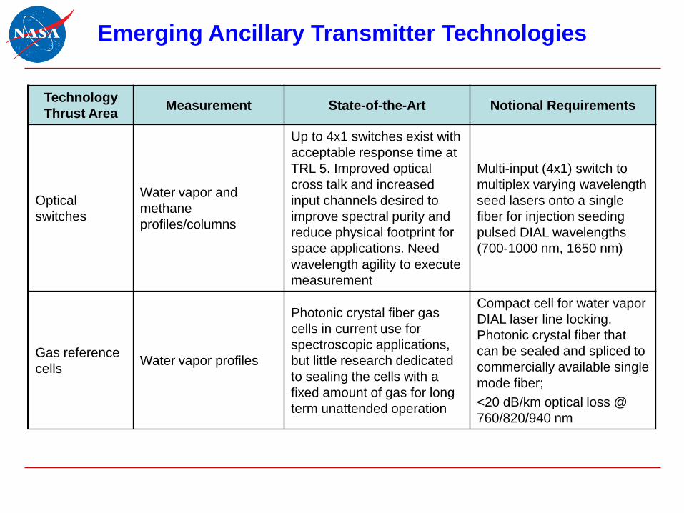
Optical
switches
Water vapor and
methane
profiles/columns
Up to 4x1 switches exist with
acceptable response time at
TRL 5. Improved optical
cross talk and increased
input channels desired to
improve spectral purity and
reduce physical footprint for
space applications. Need
wavelength agility to execute
measurement
Multi-input (4x1) switch to
multiplex varying wavelength
seed lasers onto a single
fiber for injection seeding
pulsed DIAL wavelengths
(700-1000 nm, 1650 nm)
Gas reference
cellsWater vapor profiles
Photonic crystal fiber gas
cells in current use for
spectroscopic applications,
but little research dedicated
to sealing the cells with a
fixed amount of gas for long
term unattended operation
Compact cell for water vapor
DIAL laser line locking.
Photonic crystal fiber that
can be sealed and spliced to
commercially available single
mode fiber;
<20 dB/km optical loss @
760/820/940 nm
Emerging Ancillary Transmitter Technologies

Technology
Thrust AreaMeasurement State-of-the-Art Notional Requirements
Detectors
(Including Arrays)
and Amplifiers
3-D winds
InGaAs arrays with extended
response to 2 microns
previously demonstrated but
vendors are no longer working
in this area; may require
alignment of fibers to each
detector element to maintain
heterodyne efficiency
Multi-element arrays;
QE > 80%, BW > 200MHz @ 2
microns;
QE > 50%, dark counts <1 kct/s
@ 355 nm;
QE > 70%, dark counts <1 kct/s
@ 532 nm
Detectors
(Including Arrays)
and Amplifiers
Aerosol profiles
Non-U.S. vendors not an option
due to export control/MCTL/
ITAR
Gateable within 20-50 ns, QE
50-70% @ 355/450/532 nm,
low afterpulsing, large dynamic
range, low dark noise
Emerging Detector Technologies

Technology
Thrust AreaMeasurement State-of-the-Art Notional Requirements
Large Effective
Area, Lightweight
Telescopes
(including stray light
control)
Trace gas profiles
Demonstrations of
deployable structures;
single-petal reflector
including the latch and hinge
mechanisms for mechanical
stability
3-m aperture with deployable
mechanisms;
areal density <25 kg/m2
Specialty Optics:
High Transmission
Optics, Fibers,
Polarization
Control, Wavefront
Phase Control
(Mode Matching)
Phytoplankton Iodine-filled cell
Narrow-band 532-nm notch
filter to reduce laser
backscatter to the level
comparable with
fluorescence and Raman
components in the laser-
stimulated backscatter signal
Narrowband Optical
Filters
Water vapor &
aerosol profiles
Metamaterials with large
angular acceptance; volume
Bragg gratings are an
alternative for ~10 pm
Tunable interferometric filter
for implementation in high
PRF multi-wavelength DIALs
operating in the VNIR (500-
1000 nm)
Emerging Ancillary Receiver Technologies (1/2)

Technology
Thrust AreaMeasurement State-of-the-Art Notional Requirements
Optical High
Resolution
Spectral
Analyzers
Phytoplankton
Commercial prototypes exist,
but none meet the specified
quantitative requirements and
are space-traceable
Laser-stimulated emission
(LSE) spectral detector/
analyzer;
370-800 nm, 1-3 nm
resolution, adjustable gating
Photonic
Integrated
Circuits*
Lidar/lasercomm
smallsat constellations
Utilize lasercomm
components beyond
lasers/amplifiers
Dramatic SWaP reductions to
enable smallsat applications;
1-2 microns
Emerging Ancillary Receiver Technologies (2/2)
* Cross-cutting across multiple measurements.

Technology Thrust
AreaMeasurement State-of-the-Art Notional Requirements
Intelligent sensor
health and safety*
Autonomous
monitoring & control of
lidar H&S (laser
performance/
degradation, laser life
optimization strategy)
Trim laser output power
based on performance
degradation tracking
Sensors for use in
predicting lidar health;
control software including
degradation mode models
and cost functions for
optimizing instrument
performance and/or
instrument life
Space-qualified HPC
HW and programming
tools†
Enabling technology
for smallsat and
hosted payloads
Current radiation
hardened technology is at
0.35 and 0.25 microns.
Large investment needed
to satisfy future
processing needs
Radiation hardened at
deep-submicron
microelectronic
technology (0.25, 0.18,
0.15 and 0.09 micron)
Emerging Information System Technologies
*Cross-cutting across multiple measurements.†Cross-cutting across multiple sensor modalities (not specific to lidar).

Emerging Technology Needs Roll-Up
UV
355-400 nm
VIS
400-650 nm
NIR/SWIR
700-2000 nm
MWIR
3-5 micron
Measurement3D Winds;
Water vapor;
Trop. ozone
Physical/biological
oceanography;
aerosols; topography
3D Winds; GHG; water
vapor; O2; topography;
aerosols
GHG (CH4)
Transmitter
THG of 1-m sources;
multi-stage non-linear
wavelength conversion
SHG of 1-µm sources;
multi-stage non-linear
wavelength conversion
1, 1.5, 1.8-2.6 m
sources; SHG of 1.5, 2
m sources; OPO/OPA
of 1 m sources
OPO/OPA of 1, 1.5,
2-m sources;
narrow-gap laser
diodes
Detector
GaN, MCP, DD-CCD;
Low-noise multi-
element arrays, QE >
50% @ 355 nm
Si-APD, PMT;
Gateable <50 ns, QE 50-
70% @ 450/532 nm
Lm HgCdTe APD;
Gm InGaAs APD;
PMT (to ~1.4 m);
MCP (to ~900 nm)
Lm HgCdTe APD;
HgCdTe FPAs;
SL/nBn FPAs
Aperture3-m aperture;
areal density <25 kg/m2 ▬3-m aperture;
areal density <25 kg/m2 ▬
IT*
Sub-µm HPC hardware
and tools;
intelligent sensor
management for laser
life optimization
Sub-µm HPC hardware
and tools;
intelligent sensor
management for laser life
optimization
Sub-µm HPC hardware
and tools;
intelligent sensor
management for laser life
optimization
Sub-µm HPC
hardware and tools;
intelligent sensor
management for
laser life
optimization
* Cross-cutting across multiple measurements and sensor modalities.
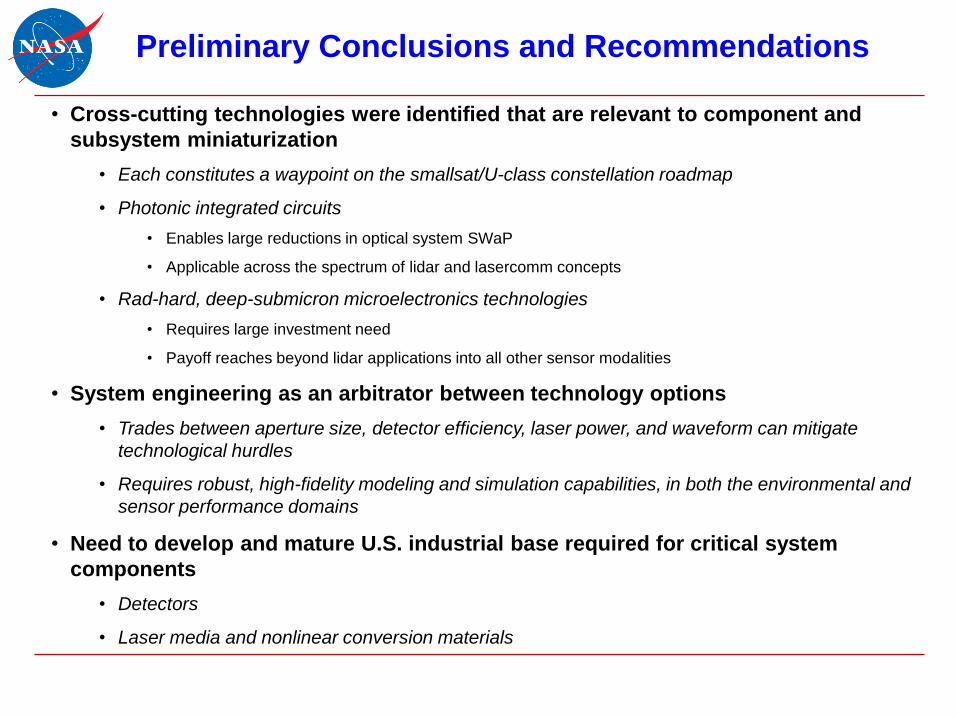
• Cross-cutting technologies were identified that are relevant to component and
subsystem miniaturization
• Each constitutes a waypoint on the smallsat/U-class constellation roadmap
• Photonic integrated circuits
• Enables large reductions in optical system SWaP
• Applicable across the spectrum of lidar and lasercomm concepts
• Rad-hard, deep-submicron microelectronics technologies
• Requires large investment need
• Payoff reaches beyond lidar applications into all other sensor modalities
• System engineering as an arbitrator between technology options
• Trades between aperture size, detector efficiency, laser power, and waveform can mitigate
technological hurdles
• Requires robust, high-fidelity modeling and simulation capabilities, in both the environmental and
sensor performance domains
• Need to develop and mature U.S. industrial base required for critical system
components
• Detectors
• Laser media and nonlinear conversion materials
Preliminary Conclusions and Recommendations

Questions & Comments

NASA ESTO Lidar Technology Status
Evaluation:
Community Input

Q1. Will we be able to download a copy of the charts presented today?
Ans – Yes, within two weeks.
Q2. What is the driver for 2-µm wavelength transmitters for wind lidar?
Ans – The answer to this question has roots going back ~25 years, when it was believed that the 1.5-
µm materials didn’t have the energy storage capacity to produce the large pulses considered
necessary, whereas modeling had indicated that the 2-µm materials would be able to do so. Given the
advances in 1.5-µm technology since it would be prudent to re-evaluate this question.
Q3. Is there a reason the water vapor profiling wavelengths are focused on 700-900 nm? Have telecomm
wavelengths been ruled out?
Ans – Current techniques are in line with water transitions – that’s why those wavelengths were
chosen.
Ans – There are strong bands within the 1.5-µm band, but you don’t get the same scattering. They can
be used for column measurements but most aren’t focusing on that.
Q4. Adaptive sensors as future technology were not addressed under transmitters, does this need to be
developed for both C&DH and transmitter or each?
Ans – No, fiber front ends offer adaptability for controlling signal properties.
Ans – Define an instrument suite to address the health of the laser. We can use this info to predict and
monitor the health of the transmitter.
Ans – It also comes in with active manipulation of both transmitter and receiver subsystems.
Community Feedback: Q&A (1/3)
Q5. Concerning free-space optical comms for downlink, what about leveraging multiple platforms?
Ans – There is a trade with how much info can be compressed. There is a limit before losing resolution
of what you’re trying to track. You can also use relays (TDRS type of advancements). Each mission
would have to balance smart sensing/compressive sensing, data compression, and downlink
capabilities during their engineering phase.
Q6. Why no mention of larger arrays and higher QE needs? Are there new types of telescopes (DARPA)?
Ans – Large arrays are an area of interest and we are attempting to highlight this in the presentation.
There are some promising candidates for solid state detectors.
Q7. Is there info on link budgets, array size, timing jitter, and system trades? MIT has been working on
asynchronous arrays.
Ans – Will direct this question to the NASA center POCs.
Ans – POCs are also in the report.
Ans – I am familiar with the MIT work and will reach out.
Q8. Wavefront agility is a ~TRL2 emerging technology under development for advanced lidar concepts.
Ans – We will ensure that it is discussed in the Final Report.
Q9. Will NASA fund ozone measurements?
Ans – It remains to be seen what NASA chooses in their responses to solicitations.
Community Feedback: Q&A (2/3)

Q10. Titanium carbide for radiation hardening? Could you discuss rad-hard materials?
Ans – Titanium-sapphire has been used, the doubler for CALIPSO is discussed. LBO is very durable
and is often the material of choice.
Q11. Is there an interest in distributed aperture receivers?
Ans – Yes, and these will be treated in the Final Report.
Q12. 400-480 nm is probably too blue for oceanographic measurements. The optimum is ~480 nm.
Ans – We will revisit the issue with the originators and correct if necessary.
Q13. There seems to be no mention of off-axis multiple scattering lidar concepts?
Ans – Although not explicitly mentioned in today’s presentations, the multiple scattering aerosol lidar
concept is treated in the draft Final Report. Its signature technical requirement comes through in our
charts as a need for wide-angle acceptance receiver technologies.
Q14. There seems to be no mention of frequency combs?
Ans – They were not mentioned today, but will be treated in the Final Report.
Q15. How long will you continue receiving White Papers?
Ans – The on-line repository will remain open until about mid-March.
Community Feedback: Q&A (3/3)

C1. Repository for white papers: http://dev.blinex.com/LIDARUpload/
C2. Currently, there is an interest in blue lasers, but the statement that the focus is mainly on
oceanographic measurements is an understatement. Also, there is interest in other atmospheric
gases (e.g., NOx, ammonia).
C3. Autonomous software (algorithms) for improving performance developed for the ground is not time
intensive. Need algorithms to perform better on orbit. System Engineering and System
(“Integrated”) Modeling for various performance parameters throughout. This may help with cost for
an overall mission and also with upfront design.
C4. GRACE-FO optical link met the needs for GRACE-II, but that was based on the 2007 decadal
survey and the community is now asking for other approaches to deal with aliasing effects.
Community Feedback: Comments

Backup

TRL Definitions
TRL Definition Hardware
Description Software
Description Exit Criteria
1
Basic principles observed and reported
Scientific knowledge generated underpinning hardware technology concepts/applications.
Scientific knowledge generated underpinning basic properties of software architecture and mathematical formulation.
Peer reviewed publication of research underlying the proposed concept/application.
2
Technology concept and/or application formulated
Invention begins, practical applications is identified but is speculative, no experimental proof or detailed analysis is available to support the conjecture.
Practical application is identified but is speculative; no experimental proof or detailed analysis is available to support the conjecture. Basic properties of algorithms, representations, and concepts defined. Basic principles coded. Experiments performed with synthetic data.
Documented description of the application/concept that addresses feasibility and benefit.
3
Analytical and experimental critical function and/or characteristic proof-of- concept
Analytical studies place the technology in an appropriate context and laboratory demonstrations, modeling and simulation validate analytical prediction.
Development of limited functionality to validate critical properties and predictions using non-integrated software components.
Documented analytical/experimental results validating predictions of key parameters.

TRL Definitions (cont.)
TRL Definition Hardware
Description Software
Description Exit Criteria
4
Component and/or breadboard validation in laboratory environment.
A low fidelity system/component breadboard is built and operated to demonstrate basic functionality and critical test environments, and associated performance predictions are defined relative to final operating environment.
Key, functionality critical software components are integrated and functionally validated to establish interoperability and begin architecture development. Relevant environments defined and performance in the environment predicted.
Documented test performance demonstrating agreement with analytical predictions. Documented definition of relevant environment.
5
Component and/or breadboard validation in relevant environment.
A medium fidelity system/component brassboard is built and operated to demonstrate overall performance in a simulated operational environment with realistic support elements that demonstrate overall performance in critical areas. Performance predictions are made for subsequent development phases.
End-to-end software elements implemented and interfaced with existing systems/simulations conforming to target environment. End-to-end software system tested in relevant environment, meeting predicted performance. Operational environment performance predicted. Prototype implementations developed.
Documented test performance demonstrating agreement with analytical predictions. Documented definition of scaling requirements.

TRL Definitions (cont.)
TRL Definition Hardware
Description Software
Description Exit Criteria
6
System/sub-system model or prototype demonstration in a relevant environment.
A high fidelity system/component prototype that adequately addresses all critical scaling issues is built and operated in a relevant environment to demonstrate operations under critical environmental conditions.
Prototype implementations of the software demonstrated on full-scale, realistic problems. Partially integrated with existing hardware/software systems. Limited documentation available. Engineering feasibility fully demonstrated.
Documented test performance demonstrating agreement with analytical predictions.