nasa cr-134545 bcac 06-11499 the results of a · pdf filethe effect of the refan nacelles on...
TRANSCRIPT

NASA CR-134545
BCAC 06-11499
THE RESULTS OF A HIGH-SPEED WIND TUNNEL TEST TO INVESTIGATE
THE EFFECTS OF THE NASA REFAN JT8D ENGINE NACELLES
ON THE STABILITY AND CONTROL CHARACTERISTICS
OF THE BOEING 727 AIRPLANE
by E. A. Kupcis
BOEING COMMERCIAL AIRPLANE COMPANY
A D IV IS ION OF
THE BOEING COMPANY
Prepared for
NATIONAL AERONAUTICS AND SPACE ADMINISTRATION
NASA Lewis Research Center
Contract NAS3-17812
IrNASA-CE-1345U5) THE R E S U L T S OF AHIGH-SPEED W I N D T U N N E L TEST TOI N V E S T I G A T E THE EFFECTS OF THE N A S ABEFAN JT8D (Boeinq Commercial AirplaneCo., Seattle) 52- p HC $5.75 CSCL 01B
N74-16726
Unclas
https://ntrs.nasa.gov/search.jsp?R=19740008613 2018-05-01T04:47:46+00:00Z
1. Report No. 2. Government Accession No.
CR-134545
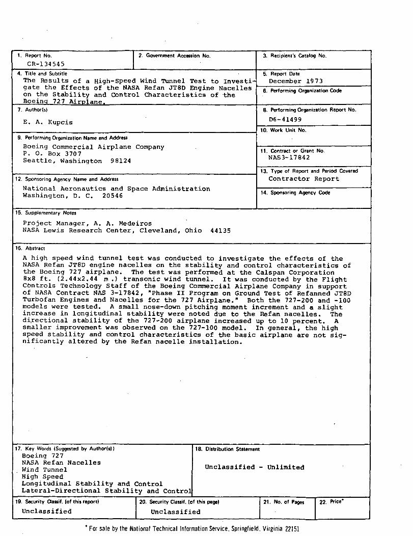
4. Title and SubtitleThe Results of a High-Speed Wind Tunnel Test to Investi-gate the Effects of the NASA Refan JT8D Engine Nacelleson the Stability and Control Characteristics of theBoeinq 727 Airplane.
7. Author(s)
E. A. Kupcis
9. Performing Organization Name and Address
Boeing Commercial Airplane CompanyP. 0. Box 3707Seattle, Washington 98124
12. Sponsoring Agency Name and Address
National Aeronautics and Space AdministrationWashington, D. C. 20546
3. Recipient's Catalog No.
5. Report DateDecember 1973
6. Performing Organization Code
B. Performing Organization Report No.
D6-41499
10. Work Unit No.
11. Contract or Grant No.NAS3-17842
13. Type of Report and Period CoveredContractor Report
14. Sponsoring Agency Code
15. Supplementary Notes
Project Manager, A. A. MedeirosNASA Lewis Research Center, Cleveland, Ohio 44135
16. Abstract
A high speed wind tunnel test was conducted to investigate the effects of theNASA Refan JT8D engine nacelles on the stability and control characteristics ofthe Boeing 727 airplane. The test was performed at the Calspan Corporation8x8 ft. (2.44x2.44 m .) transonic wind tunnel. It was conducted by the FlightControls Technology Staff of the Boeing Commercial Airplane Company in supportof NASA Contract NAS 3-17842, "Phase II Program on Ground Test of Refanned JT8DTurbofan Engines and Nacelles for the 727 Airplane." Both the 727-200 and -100models were tested. A small nose-down pitching moment increment and a slightincrease in longitudinal stability were noted due to the Refan nacelles. Thedirectional stability of the 727-200 airplane increased up to 10 percent. Asmaller improvement was observed on the 727-100 model. In general, the highspeed stability and control characteristics of the basic airplane are not sig-nificantly altered by the Refan nacelle installation.
17. Key Words (Suggested by Author(i))Boeing 727NASA Refan NacellesWind TunnelHigh SpeedLongitudinal Stability and ControlLateral-Directional Stability and Control
19. Security Qassif. (of this report)
Unclassified
18. Distribution Statement
Unclassified - Unlimited
20. Security Classif. (of this page) 21. No. of Pages 22. Price*
Unclassified
* For sale by the National Technical Information Service, Springfield, Virginia 22151
PRECEDING PAGE BLANK NOT FILMED
FOREWORD
The high-speed wind tunnel test described in this report was
performed by the Flight Controls Technology Staff of the Boeing
Commercial Airplane Company, a division of The Boeing Company,
Seattle, Washington. The work, sponsored by NASA Lewis Research
Center and reported herein, was performed in October 1973.
This report has been reviewed and is approved by:
Date -74F. C. Hall, Group EngineerFlight Controls Technology Staff
J. A .̂ TerrellChief, Staff TechnologyJT8D Refan Program
Date -2 • «?• • 7
DateK. P. Rice •• -Program ManagerJT8D Refan Program
i i i

PAGE BLANK NOT «UI»
TABLE OF CONTENTS
Page
1.0 SUMMARY ; 1
2.0 INTRODUCTION 3
3.0 NOMENCLATURE 7
4.0 MODEL AND TEST DESCRIPTION 9
4.1 MODEL DESCRIPTION 9
4.1.1 BASIC MODEL 9
4.1.2 NACELLE GEOMETRY 9
4.2 TEST FACILITY AND MODEL INSTALLATION 10
4.3 TEST PROCEDURE 10
5.0 DISCUSSION OF TEST RESULTS 13
5.1 LONGITUDINAL CHARACTERISTICS 13
5.2 LATERAL-DIRECTIONAL CHARACTERISTICS 14
6.0 CONCLUSIONS 17
7.0 REFERENCES _ _ 19
8.0 LIST OF FIGURES 21
1.0 SUMMARY
A high-speed wind tunnel model of the Boeing 727 airplane was
tested in support of the NASA Refan program. The purpose of the
test was to investigate the effects of the larger Refan nacelles
on the longitudinal and lateral-directional stability and control
characteristics of the 727 airplane.
The following conclusions are made:
1. The effect of NASA Refan nacelles on the high-speed
longitudinal stability and control characteristics of the
727-200 and -100 airplanes is minor. A small nose down
pitching moment increment and a slight increase in
longitudinal stability was noted.
2. Directional stability (^nf>) of the 727-200 airplane in-
creased up to 10% due to installation of the Refan nacelles.
A smaller improvement was .noted.on the 727-100 model.
3. In general, the high-speed stability and control character-
istics of the 727 Refan airplane are very similar to those
of the Basic 727.
PRECEDING PAGE BLANK NOT FIT,MP
2.0 INTRODUCTION
The Pratt & Whitney Aircraft JT8D-109 engine is a derivative of
the basic JT8D-9 turbofan engine, modified to incorporate a
new, larger diameter, single-stage fan with a bypass ratio of
2.03 and two supercharging low-pressure compressor stages. The
modification gives lower jet noise, increased takeoff and
cruise thrust, and lower specific fuel consumption. The use
of the JT8D-109 engine on the Boeing 727 airplane will require
enlarged side engine nacelles and center engine inlet, referred
to as the NASA Refan Configuration.
Previous wind tunnel testing has shown that aft body mounted
nacelles on a T-tail transport can have a significant effect on
the longitudinal and lateral-directional stability and control
characteristics. This effect consists of two parts: aerodynamic
forces on the nacelle itself and interference effects between
the nacelles and the empennage. -The relative^ jnagnitude of the
effect is a function of nacelle size and the location of the
nacelle relative to the vertical and horizontal tails, the body,
and wing.
In the pitch axis, larger nacelles tend to increase the stability
at low angles of attack. At high, post-stall (X's the increased
interference tends to reduce stabilizer and elevator effectiveness.
Stability changes at high Mach number due to larger nacelles
could adversely affect high speed tuck characteristics.
In the yaw axis, larger side nacelles reduce vertical tail
effectiveness due to increased aerodynamic interference. This
has an adverse effect on airplane Dutch roll characteristics.
Due to the complex nature of these effects, wind tunnel testing
was required to determine the influence of the larger NASA Refan
nacelles on the stability and control characteristics of the
727 airplane.
Low-speed wind tunnel tests were conducted at the Boeing Vertol
Wind Tunnel (May and June 1973) and at the University of
Washington Aeronautical Laboratory (August 1973). The results
of these tests are reported in Reference 1. Among the items
investigated was the effect of side nacelle location on post-
stall high angle of attack pitch characteristics. The most
favorable location for the Refan nacelle was found to be the
production JT8D-9 nacelle location.
High-speed longitudinal and lateral-directional stability and
control characteristics of the NASA Refan 727 airplane were
evaluated in the Calspan Corporation, 8x8 ft. (2.44x2.44 meter)
transonic wind tunnel in October 1973. The Refan side nacelle
location, as determined from the low-speed testing, was used.
Both the 727-200 and -100 airplanes were evaluated.
The effect of the Refan nacelles on the high-speed stability and
control characteristics of the 727 airplane as determined from
the Calspan test is the subject of this report. The emphasis
is on the 727-200 results, although some -100 data are also
given. Since high-speed aeroelastic corrections have a
considerable effect on all of the data shown, it should not be
used for absolute performance levels, but is intended only to
provide an increment between the basic and Refan 727
configurations.
PAGE BLANK NOT FILMED
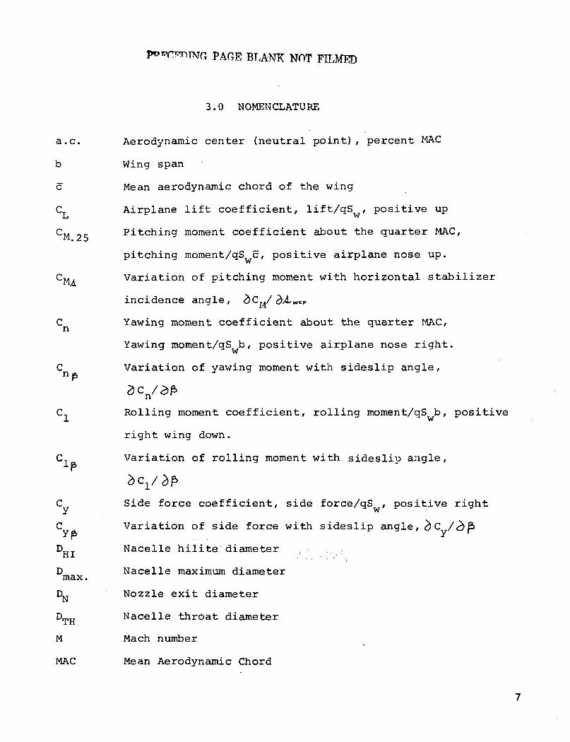
3 . 0 NOMENCLATU RE
a.c. Aerodynamic center (neutral point), percent MAC
b Wing span
c Mean aerodynamic chord of the wing
C Airplane lift coefficient, lift/qS , positive up
CM Pitching moment coefficient about the quarter MAC,^ *• £ D
pitching moment/qS c, positive airplane nose up.
CMA Variation of pitching moment with horizontal stabilizer
incidence angle, <^C,./^AWeP
C Yawing moment coefficient about the quarter MAC,
Yawing moment/qS b, positive airplane nose right.
C Variation of yawing moment with sideslip angle,
C, Rolling moment coefficient, rolling moment/qS b, positive
right wing down.
C, Variation of rolling moment with sidesliu angle,
C Side force coefficient, side force/qS , positive right
C Variation of side force with sideslip angle, ̂ C
D..T_ Nacelle hilite diameter"J. . .' . .
D Nacelle maximum diametermax.
DN Nozzle exit diameter
D̂ -j Nacelle throat diameter1 n
M Mach number
MAC Mean Aerodynamic Chord
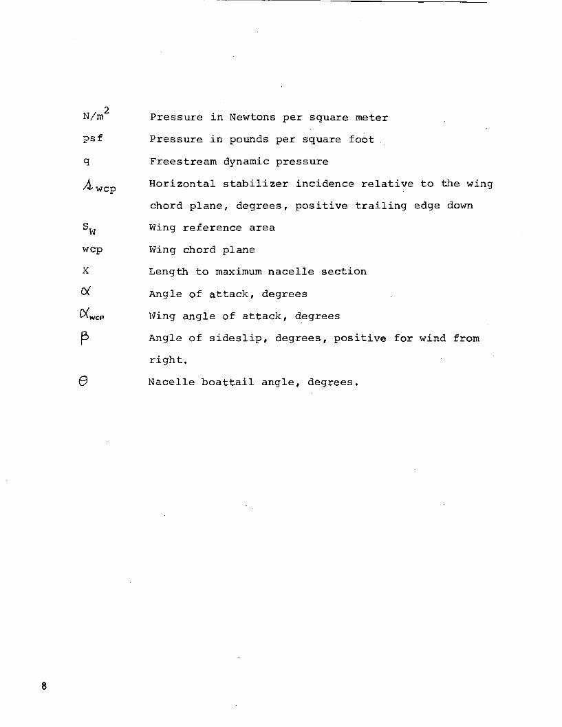
2N/m Pressure in Newtons per square meter
?sf Pressure in pounds per square foot ,
q Freestream dynamic pressure
ATT^_. Horizontal stabilizer incidence relative to the wingWt C tJ
chord plane, degrees, positive trailing edge down
S^, Wing reference area
wcp Wing chord plane
X Length to maximum nacelle section
^ Angle of attack, degrees
Wing angle of attack, degrees
Angle of sideslip, degrees, positive for wind from
right.
0 Nacelle boattail angle, degrees.

4.0 MODEL AND TEST DESCRIPTION
4.1 MODEL DESCRIPTION
4.1.1 BASIC MODEL
The model, designated TX-509I-10, is a 4.6 percent scale model
of the Boeing 727 airplane. Two, 10 foot (3.05 meter), constant
section body inserts, one forward and the other aft of the wing,
were used to permit testing both the 727-100 and -200
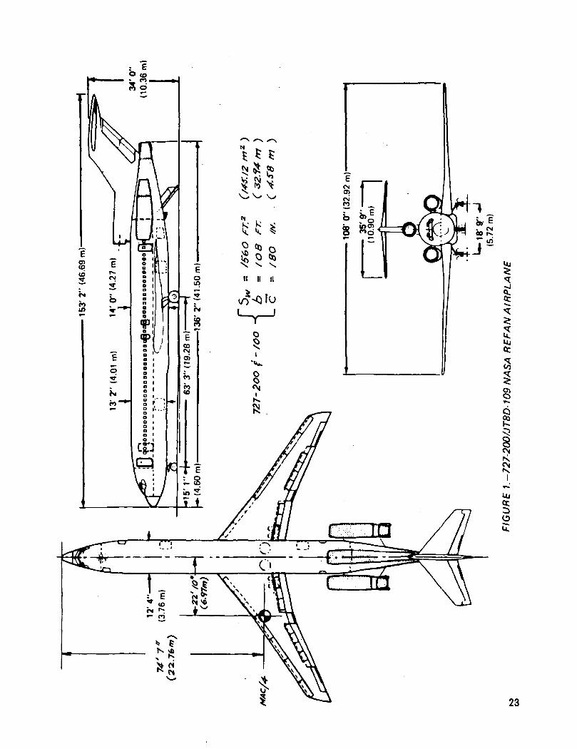
configurations. A three-view drawing of the 727-200 NASA Refan
configuration indicating the major dimensions is shown in
Figure 1. The model was sting mounted with an internal, six-
component, strain gauge balance for measuring forces and moments.
The basic model was modified to accept the NASA Refan side
nacelles and center engine inlet. Trip strips on the wing,
horizontal and vertical tail were used to simulate full scale
boundary layer conditions. The model installation and a
close-up view of the Refan nacelles are shown in Figures 2 and
3 respectively.
4.1.2 NACELLE GEOMETRY
The JT8D-109 NASA Refan engine requires a larger nacelle due to
its higher bypass ratio. The geometry of the NASA Refan and
the basic 727 nacelles as tested is shown in Figure 4. The
side nacelles were of the flow-through type and the center
engine inlet was plugged. The exit diameter of the side

nacelles tested was enlarged from that of the actual nacelles
to more correctly simulate the inlet flow field and its inter-
action with the empennage.
A plugged center engine inlet configuration was tested since the
sting mount precluded the use of a flow-through design. Previous
wind tunnel testing has shown the effects of the inlet plug to
be negligible in both pitch and yaw.
4.2 TEST FACILITY AND MODEL INSTALLATION
The test was conducted at the Calspan Corporation transonic
wind tunnel in Buffalo, N.Y. The test facility has a square
8x8 foot (2.44x2.44 meter) perforated wall test section, and is
pressurized. However, this test was run at a total pressure of
1 atmosphere for all Mach numbers. At M = .95, the maximum2
Mach number tested, dynamic pressure was 750 psf (35,850 N/m )
and Reynolds number per foot was 4.0x10 (13.1x10 per meter).
The model was installed on the Boeing 635H, six-component,
internal strain gauge balance. The Calspan Corporation double-
roll sting strut mechanism was used. This installation permitted
pitch and yaw run combinations to be made without the necessity
of a model change and tunnel shut down.
4.3 TEST PROCEDURE
The Mach number test range was 0.40 to 0.95 (some tail-off data
were obtained up to M=0.90 only). The angle of attack pitch
10

series was from -1° to +12° at low Mach number, with a lower CV
limit at high Mach number. The model was yawed between limits
of +5 degrees at constant angle of attack (0,2°, 2.2° and 4.2°) .
Six-component force and moment data were recorded and standard
wind tunnel corrections applied. Data repeatability was
considered good.
PAGE BLANK NOT FILMED
5.0 DISCUSSION OF TEST RESULTS
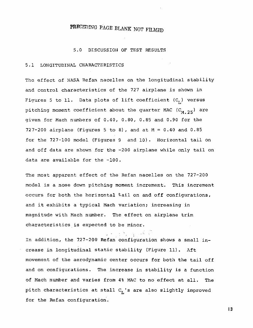
5.1 LONGITUDINAL CHARACTERISTICS
The effect of NASA Refan nacelles on the longitudinal stability
and control characteristics of the 727 airplane is shown in
Ficmres 5 to 11. Data plots of lift coefficient (CT) versusLI
pitching moment coefficient about the quarter MAC (CM -5) are
given for Mach numbers of 0.40, 0.80, 0.85 and 0.90 for the
727-200 airplane (Figures 5 to 8), and at M = 0.40 and 0.85
for the 727-100 model (Figures 9 and 10). Horizontal tail on
and off data are shown for the -200 airplane while only tail on
data are available for the -100.
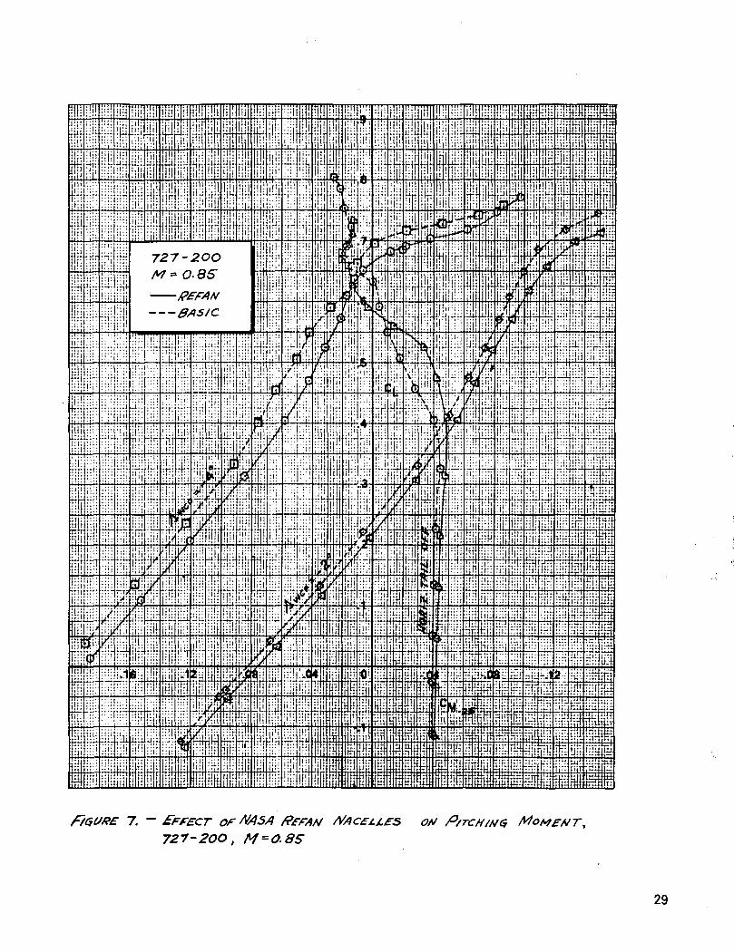
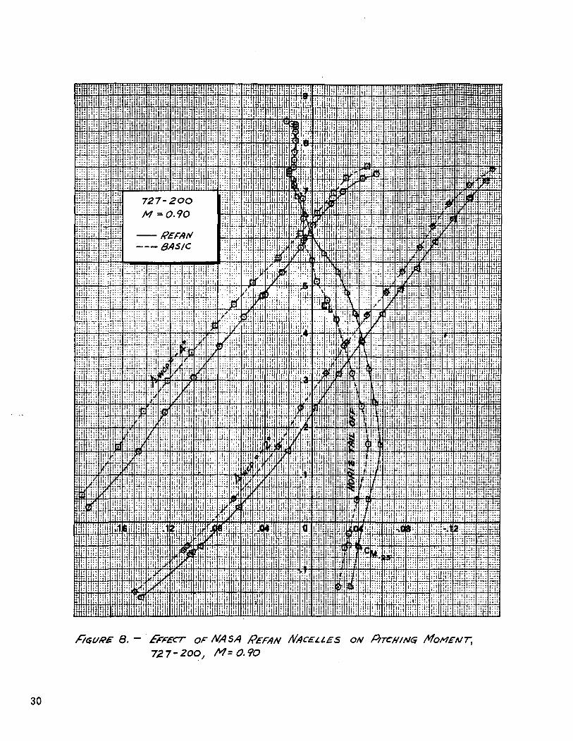
The most apparent effect of the Refan nacelles on the 727-200
model is a nose down pitching moment increment. This increment
occurs for both the horizontal tail on and off configurations,
and it exhibits a typical Mach variation; increasing in
magnitude with Mach number. The effect on airplane trim
characteristics is expected to be minor.
In addition, the 727-200 Refan configuration shows a small in-
crease in longitudinal static stability (Figure 11). Aft
movement of the aerodynamic center occurs for both the tail off
and on configurations. The increase in stability is a function
of Mach number and varies from 4% MAC to no effect at all. The
pitch characteristics at stall C's are also slightly improved
for the Refan configuration.
13

Analysis of the horizontal tail on data for the 727-200 model
indicates a small decrease in horizontal tail.effectiveness
for the Refan airplane. The apparent change in CM, is not
considered significant since it falls within the data scatter
band from previous wind tunnel tests conducted on the basic
727 airplane.
The effect of the Refan nacelles on 727-100 airplane longitudinal
characteristics (Figures 9 and 10) is similar to that of the
727-200 airplane. There is a nose down pitching moment increment
due to the Refan nacelles, with a slight increase in longitudinal
stability. For the data at a tail incidence of -4 degrees, the
nose down pitching moment increment does not appear. It is
suspected that this is due to a discrepancy in the tail incidence
setting.
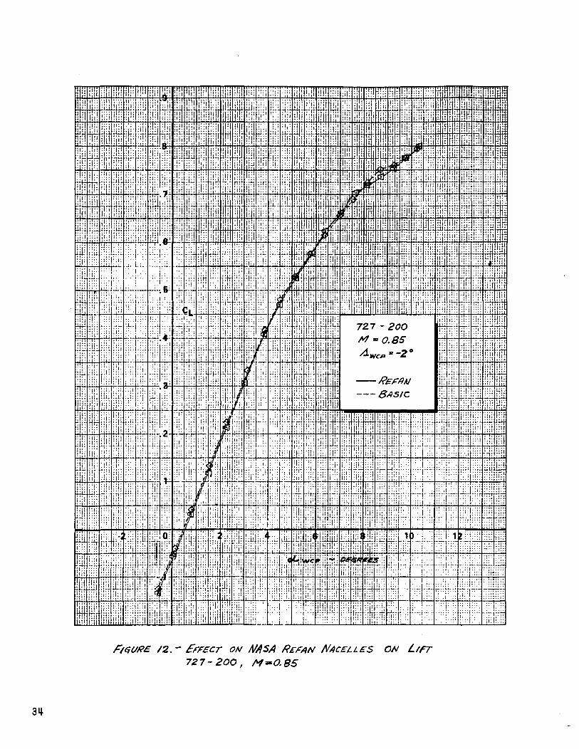
The Refan nacelle effect on airplane lift coefficient is small.
Representative data at a Mach number of 0.85 are shown in Figure
12 for the 727-200 airplane.
5.2 LATERAL-DIRECTIONAL CHARACTERISTICS
The effect of the NASA Refan nacelles on 727 airplane lateral-
directional stability is shown in Figures 13 to 20. Stability
derivatives C , C, and C are shown plotted versus Mach
number. The basic airplane and Refan configurations are compared
at wing angles of attack of (X =0.2°, 2.2° and 4.2°. The
727-200 airplane data (Figures 13 to 16) include vertical tail
14
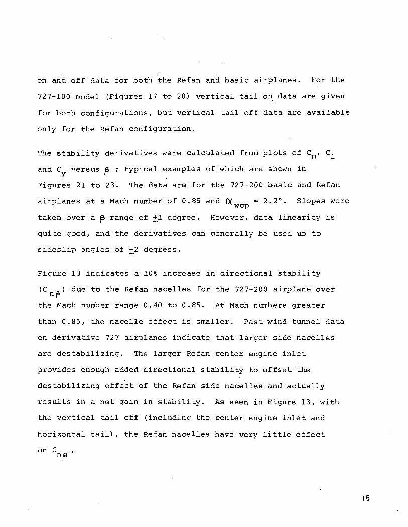
on and off data for both the Refan and basic airplanes. For the
727-100 model (Figures 17 to 20) vertical tail on data are given
for both configurations, but vertical tail off data are available
only for the Refan configuration.
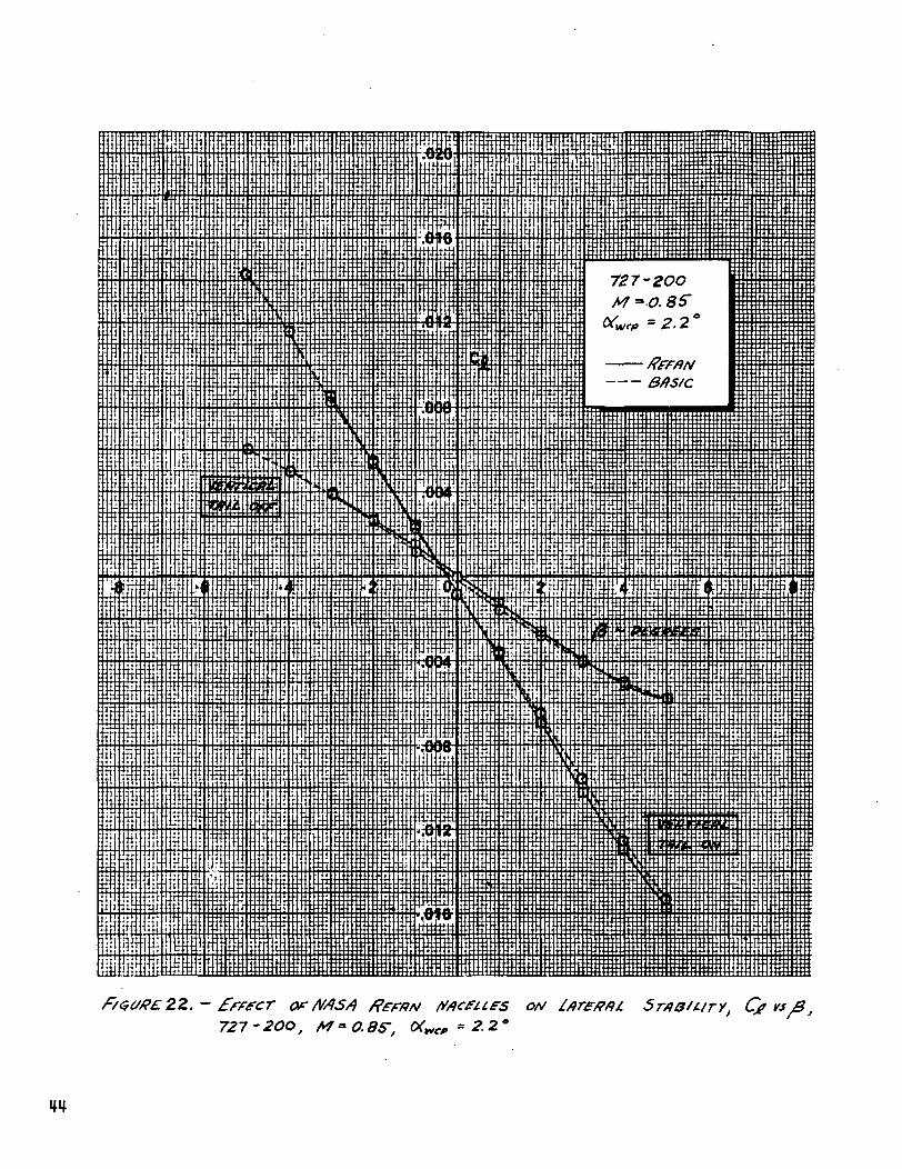
The stability derivatives were calculated from plots of Cn/ C,
and C versus & ; typical examples of which are shown in
Figures 21 to 23. The data are for the 727-200 basic and Refan
airplanes at a Mach number of 0.85 and (V =2.2°. Slopes were
taken over a 6 range of +1 degree. However, data linearity is
quite good, and the derivatives can generally be used up to
sideslip angles of +2 degrees.
Figure 13 indicates a 10% increase in directional stability
(C a) due to the Refan nacelles for the 727-200 airplane overnPthe Mach number range 0.40 to 0.85. At Mach numbers greater
than 0.85, the nacelle effect is smaller. Past wind tunnel data
on derivative 727 airplanes indicate that larger side nacelles
are destabilizing. The larger Refan center engine inlet
provides enough added directional stability to offset the
destabilizing effect of the Refan side nacelles and actually
results in a net gain in stability. As seen in Figure 13, with
the vertical tail off (including the center engine inlet and
horizontal tail), the Refan nacelles have very little effect
° n C '
15

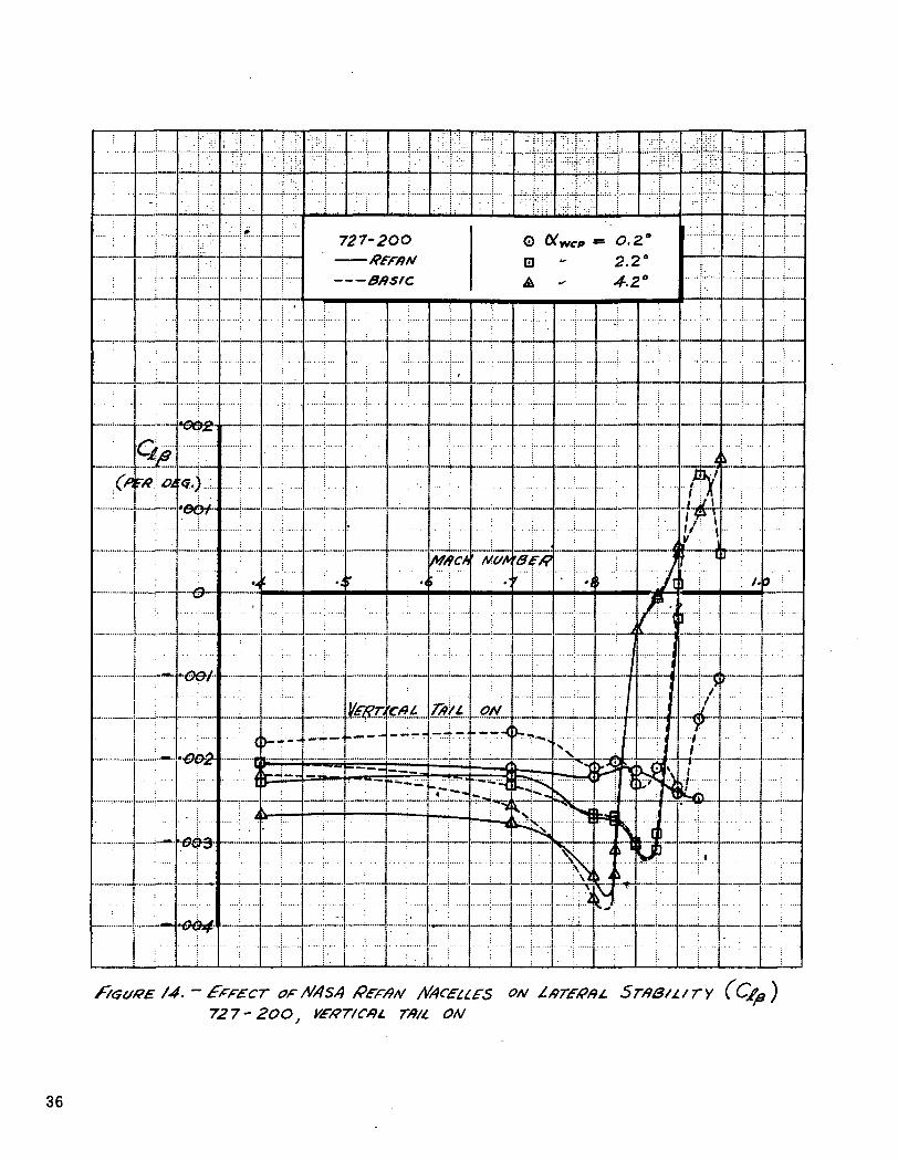
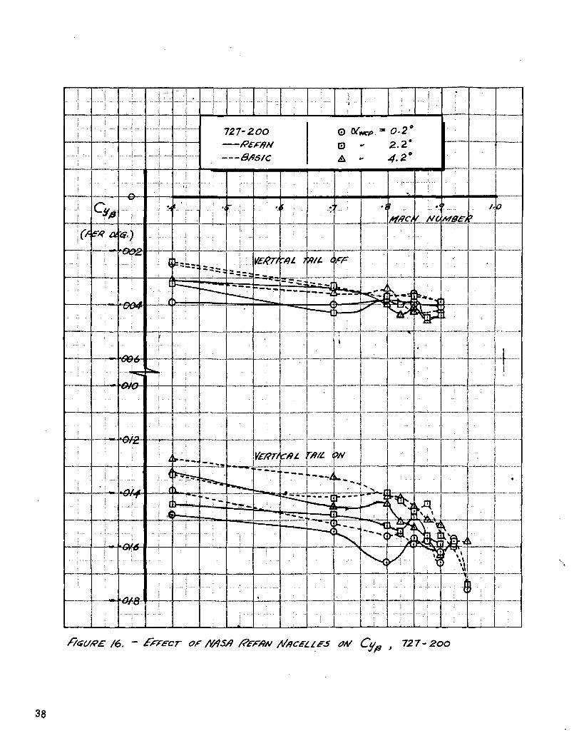
The lateral stability derivative C,B and side force derivative
C for the 727-200 airplane (Figures 14 to 16) exhibit
trends which are consistent with the observed increase in C .nPVertical tail on C, a and C.. „ are larger for the Refan
lp Yp
configuration at the lower Mach numbers, with the vertical tail
off data showing very little effect of Refan nacelles.
Refan nacelle effects on 727-100 lateral-directional stability
are shown in Figures 17 to 20. The data indicate a slight
increase in directional stability (Cna ) at low Mach number due
to the Refan nacelles. However, the effect is not as large
or as well defined as that for the 727-200 airplane. C -, „•"-P
is essentially identical for the basic and Refan configurations.
The increase in Cv at low Mach number is very similar to that•* P
seen on the 727-200.
The effect of the Refan nacelles on the 727-100 airplane is less
pronounced than on the -200 due to the shorter tail arm of the
former. The side force (C ) increment is essentially the samey P
for both airplanes, whereas the Refan effect on moments
is substantially less on the -100 airplane.
16

6.0 CONCLUSIONS
The effects of installing the P&W JT8D-109 NASA Refan nacelles
on the Boeing 727 airplane were investigated in a high-speed
wind tunnel test. Longitudinal and lateral-directional
stability and control characteristics of the 727-200 and -100
models were evaluated.
Refan nacelle effects on longitudinal stability and control
characteristics for both the 727-200 and -100 airplanes were
found to be small. The nacelles cause a small nose down pitching
moment and a slight increase in static stability.
727-200 airplane directional stability (Cna ) increased up to
10% due to installation of the Refan nacelles. This increase
is attributed primarily to the larger side area of the Refan
center engine inlet. The 727-100 model showed only a slight
increase in Cna due to the Refan nacelles. The nacelle effect
on the roll and side force derivatives, C,_ & C followed theip y p
same trend as that observed for Cnp
In general, the high-speed stability and control characteristics
of the basic and Refan 727 airplanes are very similar.
17

7.0 REFERENCES
1. M. D. Shirkey, "The Results of Low-Speed Wind Tunnel Tests
to investigate the Effects of the NASA Refan
JT8D Engine Nacelles on the Stability and
Control Characteristics of the Boeing 727-200."
NASA CR-134503, October 1973.
19

PRECEDING PAGE BLANK NOT FILIffiD
8.0 LIST OF FIGURES
FigureNo. Title Page
1 727-200/JT8D-109 NASA Refan Airplane 23
2 727-200/JT8D-109 NASA Refan Model Installed 24in the Calspan Corporation TransonicWind Tunnel
3 727-200/JT8D-109 NASA Refan Nacelle Instal- 25lation
4 Nacelle Geometry As Tested 26
5 Effect of NASA Refan Nacelles on Pitching 27Moment, 727-200, M = 0.40
6 Effect of NASA Refan Nacelles on Pitching 28Moment, 727-200, M = 0.80
7 Effect of NASA Refan Nacelles on Pitching 29Moment, 727-200, M = 0.85
8 Effect of NASA Refan Nacelles on Pitching 30Moment, 727-200, M = 0.90
9 Effect of NASA Refan Nacelles on Pitching 31Moment, 727-100, M =0.40
10 Effect of NASA Refan Nacelles on Pitching 32Moment, 727-100, M = 0.85
11 Effect of NASA Refan Nacelles on 33Longitudinal Stability, 727-200, CT =0.30LI
12 Effect of NASA Refan Nacelles on Lift, 34727-200, M = 0.85
13 Effect of NASA Refan Nacelles on 35Directional Stability (Cnp), 727-200
14 Effect of NASA Refan Nacelles on Lateral 36Stability (Gig,), 727-200, Vertical Tail On
15 Effect of NASA Refan Nacelles on Lateral 37Stability (ClB), 727-200, Vertical TailOff ^
21

FigureNo. Title Page
16 Effect of NASA Refan Nacelles on Cy , 38727-200 "
17 Effect of NASA Refan Nacelles on Directional 39Stability (C _ ), 727-100np
18 Effect of NASA Refan Nacelles on Lateral 40Stability (C,fl ), 727-100, Vertical TailOn r
19 727-100 Refan Lateral Stability (C,& ) , 41Vertical Tail Off p
20 Effect of NASA Refan Nacelles on C , 42727-100 Y"
21 Effect of NASA Refan Nacelles on Directional 43Stability, Cn vs B , 727-200, M = 0.85,(X = 2.2°^ wcp
22 Effect of NASA Refan Nacelles on Lateral 44Stability, C± vs B , 727-200, M = 0.85,(X = 2.2°.*-* wcp
23 Effect of NASA Refan NAcelles on Side Force, 45Cv vs B , 727-200, M = 0.85, (X _ = 2.2°
J! | WCp
22
Uj
-̂Jex.QC
Ujtt
i§
1
UjOC
23

FIGURE 2.—727-200/JT8D-109 NASA REFAN MODEL INSTALLED IN THECALSPAN CORPORATION TRANSONIC HIND TUNNEL
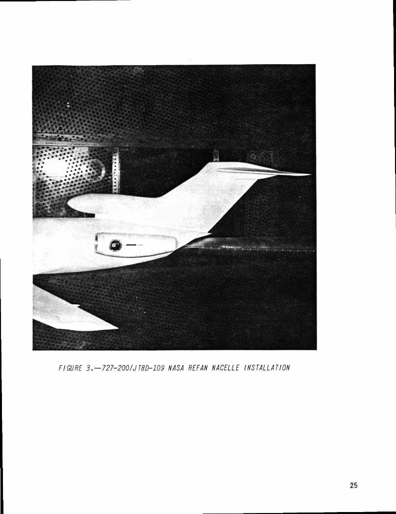
FIGURE 3. — 727-200/JT8D-109 NASA REFAN NACELLE INSTALLATION
25

NACELLE PLAN VIEW
Nacelle length, in. (cm)
Maximum diameter, Dm_ , in. (cm)
Nozzle exit diameter, DN. in. (cm)
Productionside
nacelleJT8D-9
/88. 2 (478-0)
Sf.O (/??.*)
34-1 (&.6)
Length to maximum section, X, in. (cm) 30.0 f 76-2)
Throat diameter, D-pH, in. (cm)
Hilite diameter, DH), in. (cm)
Tail pipe boattail angle, 6, deg (rad)
38.0 (96.S)
42.0 (/06.7)
8.S- (o./48)
NASA refanside
nacelleJT8D-109
233. / (S72./)
62.0 (/57.5)
43. 0 (/09.2)
33.5- (8S-f)
46.7 (//0.6~)
S2.2. (/32.6)
/<?./ (&/76)
Productioncenterinlet
JT8D-9
—
S/.O (./29.S)
Pi.VGG£D
32.6 (82-8}
PI. i/<s$eo
f>LVGG£O
—
NASA refancenterinlet
JT8D-109
—
6,4.8 (/6J-6)
Plt/fGE'D
34.9 (88.6)
Pil/GG&D
Pi. (J&iEO
—
FIGURE 4.-NACELLE GEOMETR Y AS TESTED
26

S. — frrecr of727-2OO,
ON
27

F/GUf?£. 6. - FfFECr OF /VrfSA
7Z7-200, M = O.QOMACfLL£S ON P/TCHWQ
28
7. — £Ff£CT OfWJSA727- 2OO, M =
/VAC£LJ.£S OfJ
29
F/GUGE 8. - ffFECr Of
72T- 2OO;
&EFAN NACELLES ON PITCHING
= O.9O
30

9. -727-/00,
ON P/rcft VA/G
31

/O. - £ff£CT OF A/tfSd REFAN fl/Acet.tes OH P/rcntfjG7^7-/00, M= O.8S
32

II. - £rF£cr OF /V4S/)727-200J CL= 0.
33
/2.- £ff£CT ON727-200
NACELLES ON L/FT

13. - frrecr of tfASA ff£F*N727-200
Srwury
35
727-2 OO#fntABflsrc
/4. - er Ms/) fifrAA/ A/AczufS ON £0T£fff)L STAB/I/TY727-2OO, Vf#TtCf)L TA/L ON
36

/S. - £fffcr or WSA ffffAA/ WCfLLES ON727 -2.00, VWTICtii- TfHL OFF
Sr/90/i/ry (C/g )
37
727- 2oo
38

17. ~ fiiac£Lt.£S OH O/fffCTtOM0L727 -
39

721'-/OO,


or 727-/OO

727-200M'0.85'
21. ~727-200 2.2.'
727 - 200, M=0. 85 ', 2. 2 *SrflB/ttrY, Cf vs

23. ~ OF MASA o/v727-200