nasa a microprocessor, and (2) syndrome calculation by using the g(x) encoding shift register....
TRANSCRIPT

NASA Technical Paper 1286
A Decoding Procedurefor the Reed-Solomon Codes
Raymond S. Lim ff€ \̂ IP* u *,
^J £3 w
AUGUST 1978
NASA
https://ntrs.nasa.gov/search.jsp?R=19780022919 2018-05-15T06:26:15+00:00Z

NASA Technical Paper 1286
A Decoding Procedurefor the Reed-Solomon Codes
Raymond S. LimAmes Research CenterMoffett Field, California
NASANational Aeronauticsand Space Administration
Scientific and TechnicalInformation Office
1978

SYMBOLS
d minimum (Hamming) distance between code words in a code
E(x) error polynomial
e order of an element in GF(2 )
e. error value at location X. of received codewordJ J
G generator matrix of a code
GF(2m) Galois field of 2™ elements
g(x) generator polynomial of a cyclic code
H parity-check matrix of a code
k number of information symbols in a code
M(x) message polynomial
m a positive integer
m(x) minimum polynomial
n code length (total number of symbols in a code)
(n,k) linear block code with parameters n and k
p number of errors in received codeword
p(x) primitive polynomial
q a positive integer defines the numbers of element in the Galois field
R(x) received polynomial
r(x) remainder polynomial
S syndrome of a parity check
S. a syndrome component calculated by root substitution method
S.^ a syndrome component calculated by R(x)/g(x)
t error correcting capability of a code
V(x) transmitted polynomial
Preceding Page Blank iii

X. error location at jth position of received codeword
a primitive element of GF(2 )
B error location number
a(x) error location polynomial
IV

A DECODING PROCEDURE FOR THE REED-SOLOMON CODES
Raymond S. Lira
Ames Research Center
SUMMARY
This paper describes a decoding procedure for the (n,k) t-error-correcting Reed-Solomon (RS) code, and an implementation of the (31,15) RScode for the I4-TENEX central system. This code can be used for error cor-rection in large archival memory systems. The principal features of thedecoder are (1) a Galois field arithmetic unit implemented by microprogram-ming a microprocessor, and (2) syndrome calculation by using the g(x)encoding shift register. Complete decoding of the (31,15) code is expectedto take less than 500 ysec. The syndrome calculation is performed by hard-ware using the encoding shift register and a modified Chien search. Theerror location polynomial is computed by using Lin's table, which is an inter-pretation of Berlekamp's iterative algorithm. The error location numbers arecalculated by using the Chien search. Finally, the error values are computedby using Forney's method.
PROLOGUE
Historically, in the development of algebraic coding theory, the Reed-Solomon (RS) codes were recognized as the most powerful and elegant, and alsothe most complicated, block codes to decode. These codes were first describedby I. S. Reed and G. Solomon in 1960. A systematic decoding algorithm was notdiscovered until 1968 by E. Berlekamp. Because of their complexity, the RScodes are not widely used except when no other codes are suitable.
In 1968, a (63,53) RS code with code symbols from GF(26) was used tosalvage the IBM Photo-Digital Storage System. In 1975, a (4095,4001) RS codewith code symbols from GF(212) was used to make the magnetic tape archivaldata storage system viable at the Bureau of the Census, Department of Com-merce. In 1975-1976, a (31,15) RS code with code symbols from GF(25) wasdesigned by E. Berlekamp for use in a classified defense communication system.Before proceeding with a description of decoding the RS codes, it is felt thatthe following poems selected to amplify the coding spirit are appropriate.

In Galois Fields*
In Galois fields, full of flowersprimitive elements dance for hoursclimbing sequentially through the treesand shouting occasional parities
The syndromes like ghosts in the misty dampfeed the smoldering fires of the Berlekampand high-flying exponents sometimes are downedon the jagged peaks of the Gilbert bound.
Message and Clarity
A message with content and clarityHas gotten to be quite a rarity.To combat the terror of serious error,Use bits of appropriate parity.
INTRODUCTION
With present technology, very large memory systems (>1012 bits) designedfor the archival storage of digital data are critically dependent on elec-tronic error correction systems (EECS) for ensuring system viability andintegrity (refs. 1, 2). In the IBM 3850 Mass Storage System, the EECS usedis an Extended Group Coded Recording capable of correcting up to 32 8-bitbytes of data in a 208-byte data block. In the CDC 38500 Mass Memory System,the EECS used is a modified Group Coded Recording similar to that used in theIBM 2400 Series magnetic type systems.
The use of magnetic tape systems for archival storage of digital datadepended even more critically on EECS to make them viable. The EECS devisedby Brown and Sellers, which was used in the IBM 2400 series magnetic tapesystem, is not adequate for long-term archival storage of data (refs. 3-5).
At the Institute for Advanced Computation (IAC), archival storage systemssuch as the UNICON 690 (or UNICON 190), magnetic tape systems, and other massmemory systems are no exceptions. The viability of these systems dependscritically on EECS. For the Institute, instead of designing a different EECStailored to each particular archival system, it is advantageous to designjust one EECS powerful enough to serve all systems within the Institute.
*By S. B. Weinstein of Bell Telephone Labs., IEEE, Trans, on Inf. Theory,March 1971, p. 220.
^From Error Correcting Codes, H. B. Mann, Ed., Wiley, N.Y., 1968.

This paper describes the (n,k) t-error-correcting Reed-Solomon (RS) codesand a decoding procedure suitable for implementation with the present technol-ogy. In particular, a (31,15) RS code is chosen as the EECS for the IAC 14-TENEX central system. This code is not a binary code, but a q-ary code withcode symbols from GF(25). It is believed that this code is powerful enoughto meet all anticipated IAC requirements. Because of the PDP-10, the PDP-11,and the ILLIAC IV computers comprising the I4-TENEX system, this code isplanned to have two modes of operation: 36-bit mode and 16/8-bit mode. Thedecoding of this code will be implemented by hardware and firmware, and con-sists of four steps: (1) the syndrome calculation is performed by hardwareusing the encoding shift register and a modified Chien search; (2) the errorlocation polynomial computation is performed by firmware by microprogramminga 2900 series microprocessor to implement the Berlekamp iterative algorithm;(3) the error location numbers calculation is performed by hardware using theChien search method; and (4) the error values computation is performed byfirmware using a method suggested by Forney. Finally, this (31,15) RS codeEECS is interfaced to the I4-TENEX system by means of a standard IAC 1011-Interface, like the Q1011 (ref. 6). With this interface, this EECS is justanother processor in the I4-TENEX central system.
The author wishes to thank Professor Shu Lin of the University of Hawaiifor his initial consultation and for reading this paper. He also thanks hiscolleagues D. K. Stevenson, G. F. Feierbach, and P. Hiss for reading and com-menting on the work reported herein.
REED-SOLOMON CODES
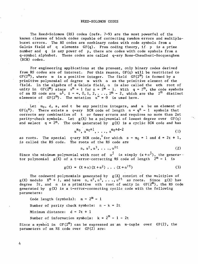
The Reed-Solomon (RS) codes (refs. 7-9) are the most powerful of theknown classes of block codes capable of correcting random errors and multiple-burst errors. The RS codes are nonbinary codes with code symbols from aGalois field of q elements GF(q). From coding theory, if p is a primenumber and q is any power of p, there are codes with code symbols from aq-symbol alphabet. These codes are called q-ary Bose-Chaudhuri-Hocquenghem(BCH) codes.
For engineering applications at the present, only binary codes derivedfrom RS codes are of interest. For this reason, GF(q) will be restricted toGF(2m), where m is a positive integer. The field GF(2m) is formed by aprimitive polynomial of degree m with a as the primitive element of thefield. In the algebra of a Galois field, a is also called the nth root ofunity in GF(2m) since an = 1 for n = 2m - 1. With q = 2m, the code symbolsof an RS code are a1, i = •», 0, 1, 2, . . . , 2m - 2, which are the 2m distinctelements of GF(2m). The notation a00 = 0 is used here.
Let m0, d, s, and t be any positive integers, and a be an element ofGF(qs). There exists a q-ary BCH code of length n = qs - 1 symbols thatcorrects any combination of t or fewer errors and requires no more than 2stparity-check symbols. Let g(X) be a polynomial of lowest degree over GF(q)and select q = 2m. The code generated by g(X) is a cyclic BCH code and has
am°, am°+1, . . ., am°+d"2 (1)
as roots. The special q-ary BCH code, for which s = mg = 1 and d = 2t + 1,is called the RS code. The roots of the RS code are
a, a2, a3, . . .,a2t (2)
Since the minimum polynomial with root of a is simply (x+a ), the genera- -tor polynomial g(X) of a t-error-correcting RS code of length 2m - 1 is
g(X) = (X+a) (X+a2) . . . (X+a2t) (3)
The codeword polynomials generated by g(X) consist of the multiples ofg(X) modulo Xn + 1, and have a, a2, a3, . . . , a2t as roots. Since g(X) hasdegree 2t, and a is a primitive nth root of unity in GF(2m), the RS codegenerated by g(X) is a t-error-correcting cyclic code with the followingparameters :
Code length (symbols): n = 2m - 1
Number of parity check symbols: n - k = 2t
Minimum distance: d = 2t + 1
Number of information symbols: k = 2 - 1 - 2t
Since a symbol in GF(2m) can be expressed as an m-tuple over GF(2), theparameters of an RS code over GF(2) are:

n = m(2m-l) bits
n-k = 2mt bits
d = 2t + 1
k = m(2m-l -2t) bits
In coding theory, if g(X) is a polynomial of degree n-k and is a fac-tor of Xn + 1, then g(X) generates an (n,k) cyclic code (ref. 7, theorem4.3; ref. 8, theorem 8.1). One way to show that an RS code generated by g(X)is cyclic is to describe the code in terms of its roots of g(X) in GF(2m).The order e of a field element a1 is the least positive integer for which(a1)6 = 1. Since (a1)11 = 1, e must be a factor of n = 2m - 1. If edivides n, then (Xe + l) divides (Xn +1) . Furthermore, an element a^ oforder e must be a root of (Xe + l), then (X + a^O divides (Xe + l), and henceit divides (Xn + l). Therefore, (Xn + l) has as roots all the n = 2m - 1nonzero elements of GF(2m). Since g(X) has a1, a2, a3, . . .,a2t as roots,g(X) is a factor of (Xn + l), and hence g(X) generates a cyclic code.
ERROR CORRECTING CAPABILITY
The RS codes over GF(2m) are very effective for correcting random andburst errors. Since each code symbol is an m-tuple (or m-bit symbol) overGF(2), a t-error-correcting RS code is capable of correcting any error pat-tern that affects t or fewer m-bit symbols. For example, since a burst oflength 3m+l cannot affect more than four m-bit symbols, a four-symbols cor-recting code can correct any single burst of length 3m+l or less. It canalso simultaneously correct any combination of two bursts of length m+1 orless because each such burst can affect no more than two symbols. At the sametime, it can correct any combination of four or less random errors. In gen-eral, the RS code with error correcting capability t can be used to correctany of the following errors:
1. All single bursts of length bj, no matter where it starts, ifb: < m(t - 1) + 1
2. Two bursts of length no longer than b2 each, no matter where eachburst starts, if b2 ^ m([t/2] -1) + 1, or any p bursts of lengthno longer than bp each, no matter where each burst starts, ifbp < m(tt/p] -1) + 1
From the above discussion, it follows that the RS code can be used to correctrandom errors, single-burst errors, or multiple-burst errors.
CODE SELECTION
The RS codes offer the designer a wide range of code parameters. Incoding theory, a block code with parameters n and k is denoted as (n,k).In table 1, a list of RS codes is tabulated for m equal to 4, 5, and 6 witht ranging from 2 to 10. For the IAC I4-TENEX system consisting of computers

TABLE 1. - LIST OF REED-SOLOMON CODES
m
4
5
6
t
23456
23456789
45678910
GF(2m)
(n,k)
(15,11)(15,9)(15,7)(15,5)(15,3)
(31,27)(31,25)(31,23)(31,21)(31,19)(31,17)(31,15)(31,13)
(63,55)(63,53)(63,51)(63,49)(63,47)(63,45)(63,43)
r = n-k = 2t
4681012
4681012141618
8101214161820
GF(2)
n = m(2m-l)
6060606060
155155155155155155155155
378378378378378378378 l
k = n-r
4436282012
1351251151Q595857565
330318306284282270258
with word lengths of 16 bits (PDP-lls), 36 bits (PDP-lOs), and 32/64 bits(ILLIAC IV), the best choice for fitting these word lengths is the (31,15)code. The formats for the 36-bit and the 16/8-bit are shown in figure 1.
BIT
NOTUSED
1 2 36 37 38 39 73 74 75 76 154
ONE PDP-1 DWORD ONE PDP-10 WORD PARITY-CHECK BITS
(a) Fitting of two PDP-10 words into 75 bits.Bit-0 is not used (always equal to zero).
o i 2
NOT USED
6 7 - 2 3 2 4 - 4 0 4 1 - 5 7 58 - 74 75 - 154
PARITY-CHECK BITS
(b) Fitting of four PDP-11 words into 75 bits.B.(i=0, 1,2, and 3) is a 16-bit word plus parity.
Figure 1. - Data formats of the (31,15) RS code for 36-bit and 16/8-bitmodes. Unused leading bits .are always zero.

ENCODING
There are two methods for encoding linear cycle codes: the serial shiftregister method and the parallel matrix method. Let M(X) be a message poly-nomial with k symbols encoded into a code polynomial (codeword) V(X) withn symbols. In the serial shift register method, encoding in systematic formis accomplished by dividing Xn~k M(X) by g(X) and appending the remainderr(X) to Xn~kM(X). That is
V(X) = r(X) + Xn~kM(X) = q(X)g(X) (4)
where q(X) is the quotient. This indicates that [r(X) +Xn~k M(X) ] is a mult-iple of g(X) and, therefore, is a code polynomial generated by g(X). Thecodeword generated is
-,_w_1 mOml • • • \_P
message* bits "
parity checkbits
and the most significant symbol of the message, mk_i, is sent first.
In the parallel matrix method, the generator matrix G has the form
G- IPkx(n-k)' W (5)
where P is a k x (n-k) matrix generated by retaining the remainder of
n-k+i(x) ,i = 0, 1,2, . . .,k - 1 (6)
and I is a kxk identity matrix. The encoding of the message vector Mto a code vector V is
V = MG (7)
The (31,15) RS code has n = 31, k = 15, m = 5, and t = 8. The primi-tive polynomial p(X) = X5 + X2 + 1 can be used to generate the 31 nonzeroelements of GF(25), as shown in table 2. The generator polynomial g(X)from equation (3) is
g(X) = (X+a)(X+a2) . . . (X+a15)(X+a16) (8)
Multiplying out the terms of g(X), the general form of g(X) is
15g(X) = X16 + ]£ ct. X1 = X16 + a15 X
15 + alt| Xlk + . . . + HI X + a0 (9)
1=0 1
The evaluation of ct^ in equation (9) is straightforward but extremely tedi-ous. In order to avoid errors, a computer program should be used in conjunc-tion with table 2 for such evaluation.
The implementation of equation (9) for encoding using the parallelmatrix method is a matrix G as shown in figure 2. Each ai,j in thematrix G is a field element in GF(25). The encoding, of M(X) into V(X) is

TABLE 2. - GALOIS FIELD OF 25.
01aex2
a3
a"a5
a6
a7
a8
a9
aioa11
a12
a13
a1"
a"
= 0= 0= 0= 0= 0= 1= 0= 0= 1= 0= 1= 1= 0= 0= 1= 1
a3
0000100101100111
a2
0001001011001111
a1
0010000100101100
a°
0100001001011001
a15 =a16 =a17 =a18 =a19 =a20 =a21 =a22 =ct23 =a24 =a25 =a26 =ct27 =a28 =a29 =a30 =
a"
1110001101110101
a3
1100011011101010
a2
100011011.1010100
a1
1111100011011101
a°
1111000110111010
Note: Elements generated by p(a) = a5 + a2 + 1.For example, a7 = (10100) means a7 = a4 + a2.
0
12
3
4
5
6
7
8
9
10
11
12
13
14
"0,0 "0.1 °0.2
"1.0 "1.1 °1.2
°2.0 a2.1 "2.2
•
•
•
°12.0 "12,1 a!2.2a!3.0 °13.1 °13.2
°14 n °U 1 a14 »
p
7 8 10 11 12 13 14 15 1617 18 ••• 2 8 2 9 3 0
. °0.13 °0.14 aO,15
Z.n a2.14 a2,15
1 0 0
0 0 1
a12.Ba12.14012.15|°a13.13c'l3.14a13.15|0
aW,13a14.14%15l0
0 0 0
0 1 0 • • • 0 0 0
0 0 0
. . . 1 0 0
. . . 0 1 0
. . . 0 0 1
Figure 2. - Generator matrix G of (15,13) Reed-Solomon codes;a. . is a field element from GF(25).

V(X) = (10)
where the message symbol ^-i is the most significant digit. From figure 2and equation (10), the parallel matrix encoding method requires about15 x 16 = 240 Galois field multipliers. Because of the logic complexity, thismethod is generally not used except for very high-speed applications, or whenG is very simple. For example, consider a 32-bit memory system built byusing n words by 4-bit integrated-circuit, random-access memory (1C RAM)chips. In such a memory system, a single chip failure will result in a 4-biterror in the 32-bit word. A t = 1 (15,13) RS code with code symbols fromGF(24) can be used for error correction in such a memory system. The Gmatrix of this code requires about 13 x 2 = 26 Galois field multipliers. Usingcurrent technology, these multipliers can be implemented by table lookup usingread-only memory (ROM) chips.
There are two shift register methods for encoding linear cyclic codes.One method uses a (n-k)-stage shift register, and the other uses a k-stageshift register (ref. 7). In practice, the (n-k)-stage shift register is mostcommonly used unless n-k is much greater than k. For encoding the (31,15)RS code, a (n-k) = 16 stages shift register (fig. 3) can be used to implementequation (4). The feedback multipliers a0, a\, . . ., 045 are field elementsof GF(2m). Each register stage is a 5-tuple shift register. Theoperation of the encoder is as follows. With SI set for feedback and S2 setto position 2, k information symbols are snifted into the encoder and simul-taneously sent to the channel. Then SI is turned to disable the feedback andS2 is turned to. position 1; the 16 parity-check symbols stored in the encodernow are shifted out to the channel, clearing the shift registers.
"(X)TO CHANNEL
Figure 3. - Encoder for (31,15) code; a± is a field element fromGF(25) and R.L is a 5-tuple shift register stage.

DECODING
In this section, an error correction procedure is described for the (n,k)t-error-correcting RS codes, and a design implementation is shown for the(31,15) t = 8 RS code. As described earlier in encoding, RS codes are non-binary codes. Therefore, the decoding procedure involves finding not onlythe error locations, but the error values as well. A t-error-correcting RScode generated by g(X) is a cyclic code, and the codewords consist of allmultiples of g(X). The degree of g(X) is 2t and its roots are a, a2, . . .,a . Since every codeword is some multiple of g(X), a, a2, . . ., a2t arealso roots of every codeword.
Let V(X) be the transmitted codeword, E(X) be the channel noise errorpattern, and R(X) be the received codeword represented as follows:
n-1V(X) = v0 + vj x + v2 x
2 + . . . + v _ :
E(X) = e0 + ex x + e2x2 + . . .+ em_1 x
11"1
R(X) = r0/+ rl x + r2x2 + . . .+ r n-1
i Xn-1
where v^, e^, and rif i = 0, 1, 2, . . .,n-l, are elements of GF(2m) . At the
decoder,
R(X) = V(X) + E(X) ' (11)
The error pattern E(X) can be described by a list of values and locations ofits nonzero components. For the decoding procedure to be described, theerror location will be given in terms of an error-location number, which issimply aJ for the (n-j)th symbol. Let X. be the error location numberand ej be the error value. Then for each nonzero component of E(X), apair of field elements (xj, ej) is required to describe that error. If E(X)has p errors, then p pairs (x̂ , e^) are required to describe the errors.Any decoding procedure is a procedure for locating these p pairs of (x•, e^)if p < t. J J
Assume that E(X) is an error pattern of p errors at locations jj,J 2» • • • > J p • Then.
E(X) =64 XJ1 + 64 X^2 + . . . + 64 XJP (12)J1 J 2 Jp
where p ^ t and 0 < J i < J 2 < . . . < J D ^ n-1. The first step in decoding isto check whether V(X) is a codeword by calculating the syndrome. If thesyndrome is zero, then either V(X) actually has no errors or V(X) has anundetectable error. In either case, V(X) is accepted as no error. A nonzerosyndrome indicates that an error has been detected; the error may or may notbe correctable. For the RS codes, the syndrome is defined as a vector Swith 2t components as follows (refs. 7, 8):
S. = R(ax) = r0 + TI a1 + r2(a
i)2 +. . .+ r^j (a1)11"1 (13)
10

for i = 1, 2, 3, . . ., 2t. Combining equations (11) and (13) gives the result
S± = V(a1) + E(aX)
Since V(a1) = 0,
S± =£=1 *j£
Combining equations (12) and (15) gives the result
j i.+ ejp(aP)
(U)
(15)
(16)t
for i = 1, 2, . . ., 2t. Expanding equation (16) gives the result
Si = aJP
(a(17)
S2t = eji(ajl)2t + eJ2(a
J2)2t +. . . + 6j (ajP)2t
Equation (17) is a set of 2t nonlinear equations which relates the 2tknown quantities of S^ to 2p unknowns, consisting of p unknown locationsand p unknown error values. Any error correction procedure is a method of
solving this set of equations for the p pairs of (e^ , cr̂ ), £ = 1, 2, . . .,• « • J X>
p. Once ajl, a"12, . . ., ajp are found, the powers ji, j2, . . ., jp will indi-cate the error locations in E(X). In general, there might be many error pat-terns that satisfy the 2t equations. If p ^ t, then the error patternwith the smallest p is the actual error pattern.
For notational convenience, let
, £ = 1, 2, . . ., p (18)
be the error location numbers (refs. 7, 8). Now equation (17) can be writtenas
S2 =
2t2t + e. 2t + + P.
' '2t
(19)
These 2t syndrome components are symmetric functions in g^, 82* • • •> 3p>which are known as power-sum symmetric functions. Next, let the error location polynomial be defined as follows:
11

where
a(X) = (1 +Bi X)(1+B2X) . . . (1+Bp X)
= a0 + D! X + a2 X2 + . . . + a Xp
OQ = 1
o-j = BI + B2 + • • • + 3p
02 = BI B2 + BI B3 + . . . -+
03 = BI 62 B3 + BI B2 Bs +
(20)
. p
•+ p_2
Op = BI B2B3 • • • B
o(X) are Bf1., g2~2>
(21)
-1The roots of o(X) are Bf , 82 » • • •» Bp , which are the inverses of theerror location numbers. It can be seen from equations (19) and (21) thatthe coefficients of o(X) are related to the syndrome components S^, 1 = 1 ,2, . . ., 2t. The coefficients o^, 02, • • • » op are known as elementary sym-metric functions of BI, B2, • • •» Bp. Therefore, if it is possible to finda(X) from the syndrome components, the error location numbers can be foundand the error pattern E(X) can be determined. In the following, an effec-tive decoding procedure is described and a design implementation for the(31,15) RS code is given. This procedure consists of four major steps asfollows (refs. 7, 8).
1.
2.
3.
4.
Calculate the syndrome S = (Si, 82, . . ., S2t) from R(X)
Calculate the error location polynomial a(X) from S
Determine the error locations X by finding the roots of a(X)
Calculate the error value from X- and S
STEP 1. SYNDROME CALCULATION
There are two methods for calculating the syndrome (S): the standardmethod, and the shift register method. -The standard method uses equation(13) because this is the way the syndrome is defined. The shift registermethod uses the g(X) encoding shift register.
isIn the standard method,, the syndrome calculation given in equation (13)
(22)
Si = r0 + r
S2 = r0 + r
S3 = r0 + r
2t = r0 + r
l a1 + r2 a2 +
! a2 + r2 a4 +
! a3 + r2 a6 +
2t i+t1 a + r2 a
n-1. . . + r , a
n-12(n-l)
. . . + r . an-1
3 (n-1). . . + r .a
n-1
. , 2t(n-l)+ . . . + r , an— 1 ,
12
In matrix form, equation (22) can be written as
S = RH = (r0 rj r2 • • • r _, i = 1, 2, 3, . . .,2t
j = 0, 1, 2, . . .,n-l
(23)
n *2t
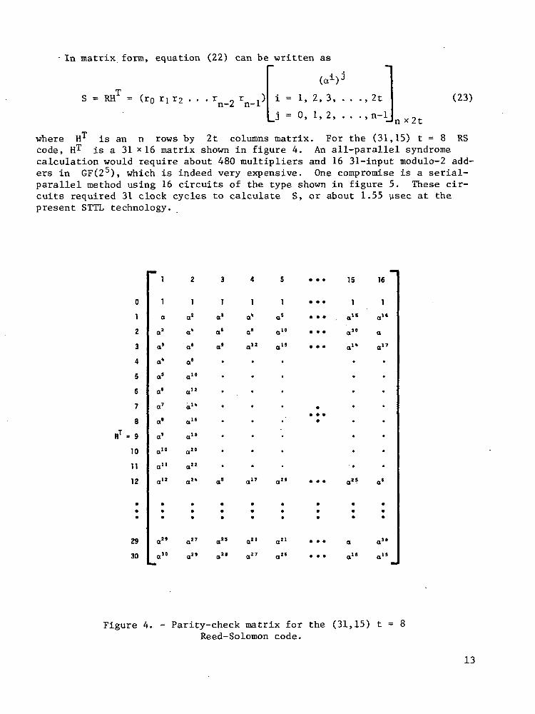
where H1 is an rows by 2t columns matrix. For the (31,15) t = 8 RScode, HT is a 31 x16 matrix shown in figure 4. An all-parallel syndromecalculation would require about 480 multipliers and 16 31-input modulo-2 add-ers in GF(25), which is indeed very expensive. One compromise is a serial-parallel method using 16 circuits of the type shown in figure 5. These cir-cuits required 31 clock cycles to calculate S, or about 1.55 usec at thepresent STTL technology.
0
12
3
4
5
6
7
8
9
10
11
12
29
30
1
1
a
a2
a3
a*
a5
os
a'
a'
o'
a"
a11
a12
a"
a"
2
1
a*
a'
a'
a'
a10
a12
a1"
a"
o"
a"
a22
a2'
a"
a2'
15
1
16
1
a"
a
Figure 4. - Parity-check matrix for the (31,15) t = 8Reed-Solomon code.
13

(a1)3./rY .,_
EG R 1
/f5
l ''S
1 REG F 1
f*GF(2S)
MULTIPLICATION
BY TABLE LOOKUP
\
/ x3 '5' 1 '
0/\
REG A
iS
f5
(ACC)
/
1 J
GENERATOR
(TABLE LOOKUP)"
Figure 5. - Circuit for calculating the syndrome component S..Approximately six STLL MSI ICs are required.
For large t(t>4), the best way to calculate the syndrome is to use theg(X) shift register. This will result in some saving in logic because thisshift register is already used for encoding. However, the S calculated byg(X) is not the same as the S calculated by R(ai) of equation (13), butthey are related. This relationship is described below.
From equation (13), let
S = (Sj, 82, • • • >
be the syndrome calculated by R(a ) with
S = R(a )
for i = 1,2,. . ., 2t. Let
S* = (S*, S*, . . .,S2*)
(24)
(25)
(26)
be the remainder calculated by dividing R(X) by g(X). The remainder S*is another form of the syndrome but S* * S. Using the Euclidean divisionalgorithm, the result of R(X)/g(X) is
R(X) = Q(X)g(X) + S*(X) (27)
where Q(X) is the quotient and
14
S*(X) = Sj* + S2* X + S3* X2 + . . . + S2* X
2t 1 (28)
is the remainder. Substituting X by a in equation (27) gives the result
R(ai) = Q(cti) g(a1) + S*(ai)
= S*(a) (29)
since Q(ai) g(a1) = 0. From equations (25), (28), and (29)', the relationshipbetween S and S* is
S. = S*(a)
i ±2S2*(a) + S3*(a) S2*(a±)2t~1 (30)
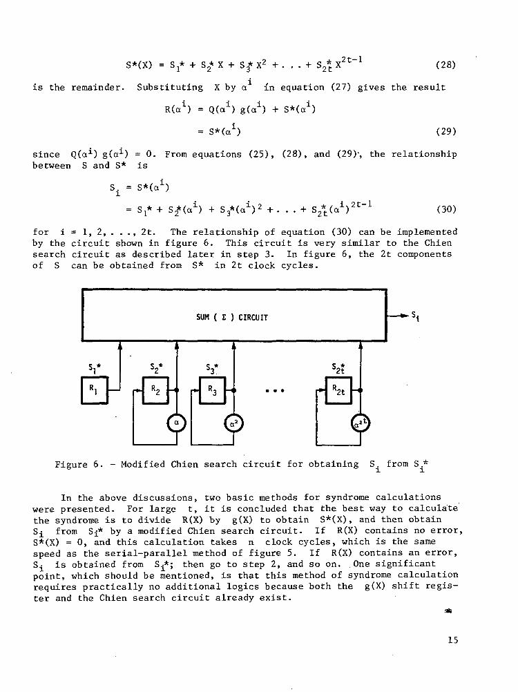
for i = 1, 2, . . ., 2t. The relationship of equation (30) can be implementedby the circuit shown in figure 6. This circuit is very similar to the Chiensearch circuit as described later in step 3. In figure 6, the 2t componentsof S can be obtained from S* in 2t clock cycles.
SUM ( Z ) CIRCUIT
V Y S3*
d>2t
Figure 6. - Modified Chien search circuit for obtaining S. from S .*
In the above discussions, two basic methods for syndrome calculationswere presented. For large t, it is concluded that the best way to calculatethe syndrome is to divide R(X) by g(X) to obtain S*(X), and then obtainS-^ from Sj* by a modified Chien search circuit. If R(X) contains no error,S*(X) = 0, and this calculation takes n clock cycles, which is the samespeed as the serial-parallel method of figure 5. If R(X) contains an error,S^ is obtained from S.-*; then go to step 2, and so on. .One significantpoint, which should be mentioned, is that this method of syndrome calculationrequires practically no additional logics because both the g(X) shift regis-ter and the Chien search circuit already exist.
SK
15

STEP 2. o(X) CALCULATION
A method for calculating the error location polynomial o(X) is givenbelow without proof. This method is the Lin's table (ref. 7), which is aninterpretation of Berlekamp's iterative algorithm (ref. 9). The same methodcan also be found in reference 8 in a slightly different form.
To find a(X), start with the table
" (y) xy o (X) d £ y — £
- 1 1 1 0 - 10 1 S1 0 012
2t
and proceed to fill out the table. Assuming that the table has all rowsfilled out up to and including the yth row, then fill out the (y+l)th rowas follows:
1. If d =0, then o(y+1)(X) = a(y)(X) and £ +J = £
2. If d * 0, find another row preceding the yth row, say the pthrow, such that the number p - £p in the last column of the tablehas the largest value and d * 0. Then
and
- a(y)(X) + d d-lX(y-p)a(X) (31)y p
= naxU , £ p+y-p] (32)
In either case,
A - Q. J. rr C J_ - „ c f~^dy+l ~ Sy+2 + °1 Sy+l + ' ' ' + a^ Sy+2-£ (33)
where the a y are the coefficients of a (X),
(X) - 1 + Ol X + a2 X2 + . . . + „ x (34)
If V(X) has exactly t errors, then the polynomial o ( X ) in the lastrow is the required a(X). If V(X) has more than t errors, then o(2Ohas degree greater than t, and generally it is not possible to locate theerrors. If V(X) has fewer than t errors, the table terminates into a modeprior to step 2t where d = d +1 = 0 and
16

The computation for o ( X ) and d combined, on the average, requiresabout 2t additions and 2t multiplications for each step. Since there are2t steps, the total is about 4t2 additions and 4t2 multiplications. Forthe (31,15) t = 8 RS code, at most 16 iterative steps are required to obtaina(X), and each step requires about 16 additions and 16 multiplications inGF(25), plus inversions. At the present technology, an economic method forperforming these computations is to have a Galois field arithmetic unit imple-mented by microprogramming a microprocessor like the 2900 series microproces-sor family. With a few hardware augmentations for inversions and specialinstruction controls, these Galois field arithmetic computations can be exe-cuted at 100 nsec per instruction. At this rate and allowing a 300% programoverhead, the o(X) calculation would take about 100 Msec.
STEP 3. DETERMINATION OF ERROR LOCATIONS
The error location numbers are the reciprocals of the roots of a(X).The roots of a(X) can be found simply by substituting 1, a, a2, . . .,an~^into a(X). Since an = 1, then a~^ = an~^. Therefore, if a^ is a root ofa(X), an~^ is an error location number and the received digit r
n_£ is in
error. If n is large, this substitution method is not desirable becausethe length of computation can be long.
If o^, i = 1, 2, . . ., p, and p < t are known from step 2, and usingthe fact that RS codes are cyclic, a procedure credited to Chien known as theChien search (refs. 7-9) can be used to find the error location numbers. Thereceived codeword R(X) is tested on a digit-by-digit basis starting with thehigh-order digit rn_} first. To decode rn_i> the decoder tests whetheran is an error location number. This is equivalent to testing whether ais a root of a(X). If a is a root, then from equations (20) and (21), theresult is
aia + ooa2+...+ a a = 1 (35)P
If equation (35) is satisfied, then an is an error location number andthe digit r ^ has an error; otherwise, rn_^ has no error. To decodern-£> the decoder tests
Ol a£ + 02 a2* + . . .+ a aP* = 1 (36)
If equation (36) is satisfied, then a^ is a root of a(X) and the digitrn_£ has an error; otherwise, rn_£ has no error.
The error location numbers testing procedure of the Chien search can beimplemented in a straightforward manner by a circuit such as that shown infigure 7. The t a-registers Rj, R2, . . ., Rt are initially stored withQI, 02, . • •, crt calculated in step 2. It should be noted that if p < t, theregister stages Rp+i» Rp+2> • • •» ̂t are st°re(l with zero sinceap+i = op+2 = • • • = ofc = 0. To test rn_j, the circuit is pulsed once. Themultiplications are performed and Oj a, 02 a2, . . ., ap aP are stored in thea-registers. The output of the SUM circuit is 1 if and only if the sum
17

Figure 7. - Chien search cyclic error location circuit.
aia + a?a2+...+ a <r = 1P
Otherwise, the output of SUM is 0 or a*. Having tested rn_i, the circuit ispulsed again; Now c^ a2, 02 a4, . . ., apa
2p are stored in the o-registers.The output of the SUM circuit is 1 if and only if the sum
Oi a2 + a? a4 + . . . + a a2 = 1P
Otherwise, the output of SUM is 0 or a1. This process continues until alln digits of R(X) are tested. The SUM output is shifted to an n-bit X^register. For example, for n = 15 and if the pattern in the X-^-register is
0 1 2 3 4 5 6 7 8 9 10 11 12 13 14
0 0 0 1 0 0 1 0 0 0 0 0 1 0 0
then the digits numbered 12, 6, and 3 of R(X) are in errors.
For the (31,15) t = 8 RS code, eight 5-tuple register stages arerequired. The multiplication circuits of a, a2, . . ., a8 can be implementedby table lookup using ROMs. The function of the SUM circuit can best be per-formed by the microprocessor since this function requires only eight XORoperations and a testing for "1" operation.
STEP 4. CALCULATION OF ERROR VALUES
The error values ,Aj
I = 1 , 2, . p, can be calculated from equation
(19) once the syndrome components Si, 82, • . ., S2t and the error locationsnumbers g2» •linear and one method of solving it for
p are known. The set of equations in equation (19) is
^is credited to Forner (refs.
18

7-9) . It should be noted that the error location number g,, is equal to
a £, and a ^ = an~^ = a~ , where a is a root of a (X) as described instep 2. Once the p pairs (Xj?, e, ) for £. = 1, 2, . . ., p are known, E(X)
in equation (12) can be determined.
To find ej , let
Z(X) = 1 + (S! +oj)X + (S2
then
. ..+ap)XP (37)
ej£ = - - - (38)
n (i + ̂ e£ l )
The computation of ej in equation (38) is relatively complex. For a
t-error-correcting RS code, and assuming E(X) has p ^ t digits in errors,the computation of Z(X) requires p+p(p+l)/2 additions and p(p+l)/2multiplications for each digit in error. Let D be the denominator of equa-tion (38). The interpretation of D is that D should consist of P - 1terms. The missing term in D is the term where 6-^ = B£. The computationof D requires p - 1 additions and (p-1) + (p-2) multiplications for eachdigit in error.
For the (31,15) t = 8 RS code, the computation of e^ in equation (38)
can be performed by the Galois field arithmetic unit implemented by micropro-grams in the 2900 series microprocessor. Assuming a 100-nsec instructionexecution rate and a 100% program overhead, the computation for each errorvalue will require about 20 usec, or about 200 ysec for all eight error values.
CONCLUSION
A decoding procedure has been described for the (n,k) t-error-correctingReed-Solomon (RS) codes. The code parameters are chosen such that the codesare cyclic so that encoding and some parts of decoding can be implemented byshift registers. In particular, a logic implementation scheme has been pre-sented for the (31,15) t = 8 RS code.' The principal features are (1) aGalois field arithmetic unit implemented by microprogramming a 2900 seriesmicroprocessor, and (2) syndrome calculation by using the g(X) encoding shiftregister. This arithmetic unit is capable of executing instructions at a100-nsec clock cycle rate. Encoding the (31,15) code would be implemented byshift registers requiring 31 clock cycles (3.1 ysec). Decoding the (31,15)code requires four steps of computation with a total decoding time of about500 ysec. With present technology, it is felt that the microprogrammable
19

microprocessor is the most feasible approach to decode this code except forthe case where n and t are small, for example, n < 15 and t < 2. For thesecases, an all-parallel method is probably more suitable.
Ames Research CenterNational Aeronautics and Space Administration
Moffett Field, California 94035, March 8, 1978
REFERENCES
1. Introduction to the IBM 3850 Mass Storage System (MSS). IBM DocumentGA32-0028-2, July 1975, p. 57; IBM 3850 Mass Storage System Installa-tion Guide. IBM Document GA32-0030-1, April 1976, p. 17.
2. 38500 Mass Storage System General Information Manual. Control Data Cor-poration Document 22294400, 1976; 38500 Mass Storage Reference Manual.Control Data Corporation Document 22083000, 1976.
3. Brown, D. T.; and Sellers, F. F., Jr.: Error Correction for IBM 800-bit-per-inch Magnetic Tape. IBM J. Res. Develop., July 1970, pp. 384-389.
4. Berlekamp, E. R. : Algebraic Codes for Improving the Reliability of TapeStorage. AFIPS Conf. Proc., vol. 44, May 19-22, 1975, pp. 497-499.
5. Poland, W. B.; Prine, G. E.; and Jones, T. L.: Archival Performance ofNASA GFSC Digital Magnetic Tape. AFIPS Conf. Proc., vol. 42, June 4-8,1973, Part II, pp. M68-M73.
6. Lim, R. S.: Technical Manual for Q1011, QM1011, and M1011: Virtual andDMA Central Memory Interface for PDP-11. IAC Report, Institute forAdvanced Computation, NASA-Ames Research Center, NASA, July 1976.
7. Lin, S.: An Introduction to Error-Correcting Codes. Prentice-Hall,Englewood Cliffs, New Jersey, 1970.
8. Peterson, W. W..; and Weldon, E. J., Jr.: Error-Correcting Codes. 2ndEdition, MIT Press, Cambridge, Mass., 1972.
9. Berlekamp, E. R.: Algebraic Coding Theory. McGraw-Hill Book Co., Inc.,New'York, 1968.
20

1. Report No. 2. Government Accession No.
NASA TP - 12864. Title and Subtitle
A DECODING PROCEDURE FOR THE REED-SOLOMON CODES
7. Author(s)
Raymond S . Lim
9. Performing Organization Name and Address
NASA Ames Research CenterMoffett Field, Calif. 94035
12. Sponsoring Agency Name and Address
National Aeronautics and Space AdministrationWashington, D. C. 20546
3. Recipient's Catalog No.
5. Report Date
August 19786. Performing Organization Code
8. Performing Organization Report No.
A-7372
10. Work Unit No.366-18-50-00-00
11. Contract or Grant No.
J3. Type of Report and Period Covered
Technical Paper
14. Sponsoring Agency Code
15. Supplementary Notes
16. Abstract
This paper describes a decoding procedure for the (n,k) t-error-correcting Reed-Solomon (RS) code, and an implementation of the (31,15) RScode for the I4-TENEX central system. This code can be used for errorcorrection in large archival memory systems. The principal features of thedecoder are (1) a Galois field arithmetic unit implemented by microprogram-ming a microprocessor, and (2) syndrome calculation by using the g(x)encoding shift register. Complete decoding of the (31,15) code isexpected to take less than 500 ysec. The syndrome calculation is performedby hardware using the encoding shift register and a modified Chien search.The error location polynomial is computed by using Lin's table, which isan interpretation of Berlekamp's iterative algorithm. The error locationnumbers are calculated by using the Chien search. Finally, the errorvalues are computed by using Forney's method.
17. Key Words (Suggested by Author(s))
Error-correcting codesMemory error correctionReliable memory systems
18. Distribution Statement
Unlimited
STAR Category - 62
19. Security Qassif. (of this report)
Unclassified20. Security Classif. (of this page)
Unclassified21. No. of Pages
24
22. Price*
$3.50
*For sale by the National Technical Information Service. Springfield, Virginia 22161NASA-Langley, 1978

National Aeronautics andSpace Administration
Washington, D.C.20546
Official Business
Penalty for Private Use, $300
THIRD-CLASS BULK RATE Postage and Fees PaidNational Aeronautics andSpace AdministrationNASA-451
NASA If Undeliverable (Section 158V