(nas-nae) w ashington dc unclassified … · this study by the national materials ... table 10...
TRANSCRIPT

/ AD-A0 861 NATIONAL MATERIALS ADVISORY BOARD (NAS-NAE) W ASHINGTON DC F/f 13/10
ANCHOR CHAIN FOR FUTURE U.S. NAVY VESSELS,(U)JUN 80 MDAgO3-78-C-0038
UNCLASSIFIED NMAS-371mmhh///////I//.EEllllllllllEE

Anchor Chain, for FutureSU.S. Navy Vessels
DTIOA-ELECTE
MAR 2 6 1981Th,e cNational Materials Advisory Board
Commission on Sociotechnical Systems
/" 1THIS DOCITN HAS BEIM APTROVID
SNMAB-371 7OR PUBLIC EELEASI AND SALE;ZISRn M5 is WILMTXD
NATIONAL RESEARCH COUNCILCOMMISSION ON SOCIOTECHNICAL SYSTEMS
NATIONAL MATERIALS ADVISORY BOARD
Chairman:Mr. William D. ManlySenior Vice PresidentCabot Corporation125 High StreetBoston, MA 02110
PastChairman:
Mr. Julius J. HarwoodDirector, Materials Science
LaboratoryEngineering and Research StaffFord Motor CompanyP. 0. Box 2053Dearborn, MI 48121
MembersDr, George S. Ansell Dr. John R. Hutchins III Dr. John J. Schanz, Jr.Dean, School of Engineering Vice President and Director of Senior SpecialistRensselaer Polytechnic Institute Research and Development Congressional Research Service-ENRTroy, NY 12181 Technical Staff Division Library of Congress
Corning Glass Works Washington, DC 20540D K wSullivan ParkDr. H. Kent Bowen Corning, NY 14830 Dr. Arnold J. SilvermanProfessor, Ceramic and Electrical Professor, Department of Geology
Engineering Dr. Sheldon E. Isakoff University of MontanaMassachusetts Institute of Technology Director, Engineering Research and Missoula, MT 5980177 Massachusetts Avenue Development DivisionCambridge, MA 02139 E. I. DuPont de Nemours & Co., Inc. Dr. Dorothy M. Simon
Wilmington, DE 19898 Vice President and Directorof Research
Dr. Van L Canady Dr. Frank E. Jaumot, Jr. AVCO CorporationSenior Planning Associate Director of Advanced Engineering 1275 King StreetMobil Chemical Company Delco Electronics Division Greenwich, CT 06830150 E. 42nd Street, Room 746 General Motors CorporationNew York, NY 10017 P. 0. Box 1104 Dr. William M. Spuron
Kokomo, IN 46901 Director, Manufacturing andQuality Control
Dr. George E. Dieter, Jr. Dr. James W. Mar Bendix CorporationDean, College of Engineering Professor, Aeronautics and 24799 Edgemont RoadUniversity of Maryland Astronautics Southfield, MI 48075College Park, MD 20742 Building 33-307
Massachusetts Institute of Technology Dr. Roger A. StrehlowDr. Joseph N. Epel Cambridge, MA 02139 Professor, Aeronautical andDr. ose N. pelAstronautical EngineeringDirector, Plastics Research and University of Illinois at UrbanaBuDevelopment Center Industrial Advisor 101 Transportation Building356 Executive Drive Industrial Development and Urbana, IL 61801Troy, MI 48084 Finance Department Dr. Michael Tenenbaum
World Bank 1644 Cambridge1818 H Street, N.W., Room D422 Flossmoor, IL 60422
Dr. Larry L. Hench Washington, DC 20431Professor and Head Dr. William A. VogelyCeramics Division Dr. R. Byron Pipes Professor and Head, DepartmentDepartment of Materials Science Director, Center for Composite of Mineral Economics
and Engineering Materials Pennsylvania State UniversityUniversity of Florida Department of Mechanical and University Park, PA 16802Gainesville, FL 32601 Aerospace Engineering
University of Delaware Dr. Albert R. C. WestwoodNewark, DE 19711 Director, Martin Marietta Labs
Dr. Robert E. Hughes Martin Marietta CorporationProfessor of Chemistry Dr. Allen S. Russell 1450 South Rolling RoadExecutive Director, Materials Vice President-Science and Baltimore, MD 21227
Science Center TechnologyDepartment of Chemistry Aluminum Company of America NMAB StaffCornell University 1501 Alcoa Building W. R. Prindle, Executive DirectorIthaca, NY 14850 Pittsburgh, PA 15219 R. V. Hemm, Executive Secretary
(1/1/80)
BIBLIOGRAPHIC DATA 1*Rpr~N-.- . ~ ,3. Recipient's Accession No.SHEET 2 A-31 -, 156 _____________
4.Title and Subtitle "Report Date -
Anchor Chain for Future U.S. Navy Vessels. Jund J t8q
7. Xlihor(s) 8. Performing Organization Rept.Committee on Anchor Chain Manufacture No. NMAB-371 [
9. Performing Organization Name and Address 10. Project/Task/Work Unit No.National Materials Advisory BoardNational Academy of Sciences 11. Conra.t/Gran No.2101 Constitution Ave., N.W.
Washington, D.C. 20418 #12. Sponsoring Organization Name and Address 13. Type of Report & Period
CoveredDepartment of Defense and the National Aeronautics '_pt,
and Space Administration _ _ _ _
15. Supplementary Notes
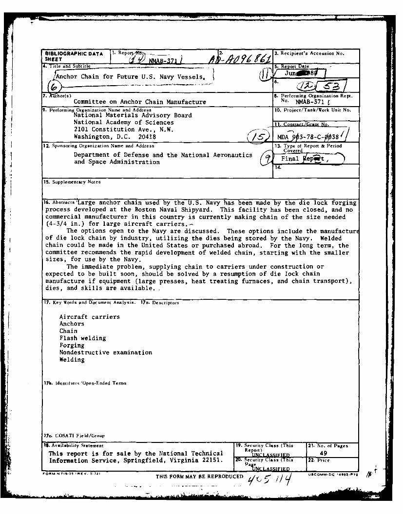
16. Abstracts Large anchor chain used by the U.S. Navy has been made by the die lock forgingprocess developed at the Boston Naval Shipyard. This facility has been closed, and nocommercial manufacturer in this country is currently making chain of the size needed(4-3/4 in.) for large aircraft carriers.-
The options open to the Navy are discussed. These options include the manufacturcof die lock chain by industry, utilizing the dies being stored by the Navy. Weldedchain could be made in the United States or purchased abroad. For the long term, thecommittee recommends the rapid development of welded chain, starting with the smallersizes, for use by the Navy.
The immediate problem, supplying chain to carriers under construction orexpected to be built soon, should be solved by a resumption of die lock chainmanufacture if equipment (large presses, heat treating furnaces, and chain transport),dies, and skills are available.-
17. Key Words and Document Analysis. 17a. Descriptors
Aircraft carriersAnchorsChainFlash weldingForgingNondestructive examinationWelding
17b. Identifiers 'Open-Ended Terms
17c. COSATI Field/Group
13. Availability Statement 19. Security Class (This 21. No. of PagesThis report is for sale by the National Technical Report)E 49
Information Service, Springfield, Virginia 22151. 20. Security Class (This 22. Price
, PaUNCLASSIFIED-
FOM TS-5INEV .1TIS FORM MAY BE REPRODUCED) Z/( 1 ,/aComm-0c 14952-P72, ,,
ANCHOR CHAIN FOR FUTURE U.S. NAVY VESSELS
Report of
Committee on Anchor Chain Manufacture
NATIONAL MATERIALS ADVISORY BOARD
Commission on Sociotechnical SystemsNational Research Council Acession o
DI A BA
U1I)~leJUTifcta
Publicatio NMAB-371 itt l ~i~
Natinal cadmy o Scince
WashigtonD.C. ode
-
1
pes
NOTICE
The project that is the subject of this report was approved bythe Governing Board of the National Research Council, whose membersare drawn from the Councils of the National Academy of Sciences, theNational Academy of Engineering, and the Institute of Medicine. Themembers of the Committee responsible for the report were chosen fortheir special competences and with regard for appropriate balance.
This report has been reviewed by a group other than the authorsaccording to procedures approved by a Report Review Committeeconsisting of members of the National Academy of Sciences, the NationalAcademy of Engineering, and the Institute of Medicine.
This study by the National Materials Advisory Board wasconducted under Department of Defense Contract No. MDA 903-78-C-0038for the Department of the Navy.
This report is for sale by the National Technical InformationService, Springfield, Virginia 22151.
Printed in the United States of America.
" ii
ABSTRACT
Large anchor chain used by the U.S. Navy has been made by the
die lock forging process developed at the Boston Naval Shipyard.This facility has been closed, and no commercial manufacturer inthis country is currently m; 'ng chain of the size needed (4-3/4 in.)for large aircraft carriers.
The options open to the Navy are discussed. These optionsinclude the manufacture of die lock chain by industry, utilizingthe dies being stored by the Navy. Welded chain could be made inthe United States or purchased abroad. For the long term, thecommittee recommends the rapid development of welded chain, startingwith the smaller sizes, for use by the Navy.
The immediate problem, supplying chain to carriers under con-struction or expected to be built soon, should be solved by aresumption of die lock chain manufacture if equipment (large presses,heat treating furnaces, and chain transport), dies, and skills areavailable.
tiii
NATIONAL MATERIALS ADVISORY BOARD
COMMITTEE ON ANCHOR CHAIN MANUFACTURE
Chairman
ADOLPH SCHAEFER, Executive Director, The Metal Properties Council, Inc.,New York, New York.
Members
FRANCIS W. BOULGER, Consultant, Columbus, Ohio.
CHARLES DECKARD, Corporate Director-Special Projects, The BendixCorporation, Southfield, Michigan.
GENE GOODWIN, Metals & Ceramics Division, Oak Ridge National Laboratory,
Oak Ridge, Tennessee.
C. MONROE HART, Rear Admiral, U.S.N. (ret.), Eyring Research Institute,Inc., Provo, Utah.
EDWARD NISBET, Supervisor, Product Metallurgy, National Forge, Irvine,Pennsylvania.
PAUL W. RAMSEY, Manager, Welding Research and Development, A.O. SmithCorporation, Milwaukee, Wisconsin.
ROBERT STOUT, Dean of the Graduate School, Lehigh University, Bethlehem,Pennsylvania.
Liaison Representatives
BRUNO L. ALIA, Chief Surveyor, Metallurgy Department, AmericanBureau of Shipping, New York, New York.
JACK W. BOLLER, Executive Director, Marine Board, National ResearchCouncil, Washington, D.C.
RANDOLPH W. KING, Executive Officer, National Academy of Engineering(formerly Executive Director, Marine Transportation Research Board,National Research Council), Washington, D.C.
GEORGE PRENTICE, Naval Sea Systems Command, Department of the Navy,
Washington, D.C.
v

STEVEN ROUSH, U.S. Coast Guard Headquarters, Washington, D.C.
GEORGE SORKIN, Consultant (formerly of the Naval Sea Systems Command,Department of the Navy), Alexandria, Virginia.
NMAB Staff
Joseph R. Lane, Staff Metallurgist
1i
I
&
1< - . -

CONTENTS
Page
Chapter 1 - INTRODUCTION 1
Chapter 2 - CONCLUSIONS/RECO44ENDATIONS 5
Chapter 3 - TECHNICAL RISKS AND CONFORMANCE TO SPECIFICATIONS 7FOR INDUSTRIAL PRODUCTION OF BOTH DIE LOCK ANDWELDED 4-3/4 IN. CHAIN
Military Specifications for Anchor Chain 7Die Lock Chain 8Flash-Butt-Welded Chain 9
Chapter 4 - NONDESTRUCTIVE EXAMINATION 13
Relevant Quality-Assurance Provisions 13Incoming Bar 13Chain Manufacture 13Nondestructive Examination 14
Chapter 5 - FAILURE MODES 17
Introduction 17Failures in Mooring Systems 17Navy Experience with Forged Chain 17Commercial Experience with Welded Chain 21Causes of Failures in Anchor Chain 27
Chapter 6 - DIE LOCK- AND FLASH-WELDED CHAIN EXPERIENCE 37
Analysis Procedure 37U.S. Navy Die Lock Chain Service Experience 37Flash-Welded Chain Experience 40
Chapter 7 - ECONOMIC ASPECTS 43
vii
A
TABLES AND FIGURES
Page
Figure 1 Processing Steps for Forging Die Lock Steel 2
Stud-Link Anchor Chain
Figure 2 Chain Manufacturing Sequence for Welded 3
Stud Links
Table 1 Failures and Causes of Failures in Parts of 19Mooring Systems in all Navy Vessels DuringJanuary 1954 Through June 1957
Table 2 Failures in Mooring Systems, by Categories, 20Listed in Navy Casualty Reports January 1, 1971Through October 30, 1979
Table 3 Summary of Notes Concerning Reasons for 22Replacement of Forged Chain Links
Table 4 Failures in Mooring Equipment of Merchant 23Ships (Welded Chain)
Table 5 Mooring Equipment Defects and Failures in Navy 25and ABS Records, by Subsystem Involved
Fable 6 Losses of Cables and Other Failures on Japanese 26Ships and Ship Losses in World Shipping
Table - Data From Laboratory Studies on Welded Anchor 30Chain
Table 8 Composition of Steel in Samples of 4-3/4 In. 33Flash-Butt-Welded Anchor Chain
Table 9 Data From Tests on Triplets of 4-3/4 In. 34Flash-Welded Alloy Steel Chain
Table 10 Defects and Failures of Ground Tackle in 38Aircraft Carriers, U.S. Navy, 1971-79
Fable 11 Defects and Failures of Ground Tackle in Medium 39Sired Ships, U.S. Navy, 1971-79
ix
rI
Page
Table 12 Types of Failure of Common Link in Destroyers, 40U.S. Navy 1971-79
Table 13 Number of Ground-Tackle Failures Reported in 41Merchant Ships, 1965-77, by Type of Equipment
Table 14 Comparison of the Dimensions of 3-3/4 In. Chain 42
Table 15 Price Comparisons for 3-3/4 In. Chain 43
x
Chapter 1
INTRODUCTION
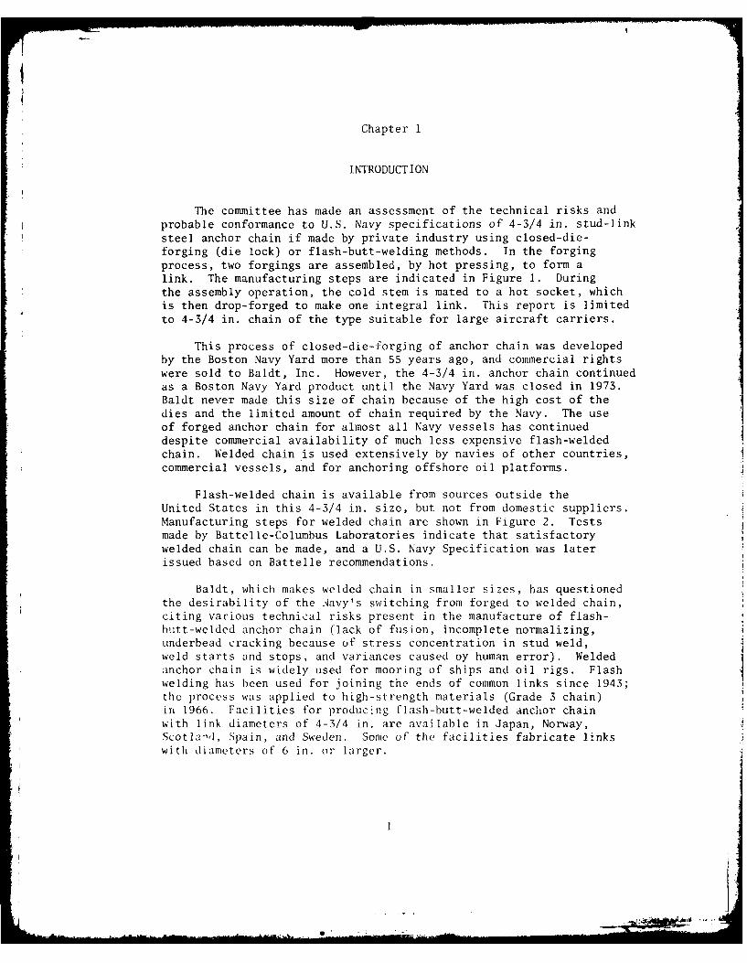
The committee has made an assessment of the technical risks andprobable conformance to U.S. Navy specifications of 4-3/4 in. stud-linksteel anchor chain if made by private industry using closed-die-forging (die lock) or flash-butt-welding methods. In the forgingprocess, two forgings are assembled, by hot pressing, to form alink. The manufacturing steps are indicated in Figure 1. Duringthe assembly operation, the cold stem is mated to a hot socket, whichis then drop-forged to make one integral link. This report is limitedto 4-3/4 in. chain of the type suitable for large aircraft carriers.
This process of closed-die-forging of anchor chain was developedby the Boston Navy Yard more than 55 years ago, and commercial rightswere sold to Baldt, Inc. However, the 4-3/4 in. anchor chain continuedas a Boston Navy Yard product until the Navy Yard was closed in 1973.Baldt never made this size of chain because of the high cost of thedies and the limited amount of chain required by the Navy. The useof forged anchor chain for almost all Navy vessels has continueddespite commercial availability of much less expensive flash-weldedchain. Welded chain is used extensively by navies of other countries,commercial vessels, and for anchoring offshore oil platforms.
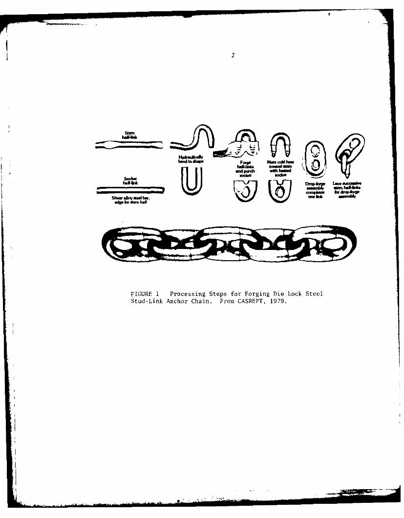
Flash-welded chain is available from sources outside theUnited States in this 4-3/4 in. size, but not from domestic suppliers.Manufacturing steps for welded chain are shown in Figure 2. Testsmade by Battelle-Columbus Laboratories indicate that satisfactorywelded chain can be made, and a U.S. Navy Specification was laterissued based on Battelle recommendations.
Baldt, which makes welded chain in smaller sizes, has questionedthe desirability of the Navy's switching from forged to welded chain,citing various technical risks present in the manufacture of flash-butt-welded anchor chain (lack of fusion, incomplete normalizing,underbead cracking because of stress concentration in stud weld,weld starts and stops, and variances caused ny human error). Weldedanchor chain is widely used for mooring of ships and oil rigs. Flashwelding has been used for joining the ends of common links since 1943;the process was applied to high-strength materials (Grade 3 chain)in 1966. Facilities for producing flash-butt-welded anchor chainwith link diameters of 4-3/4 in. are available in Japan, Norway,Scotland, Spain, and Sweden. Some of the facilities fabricate linkswith diameters of 6 in. or larger.
2
San
bdt. *ww og Mae, cold hm
Sodketmm
FIGURE 1 Processing Steps for Forging Die Lock SteelStud-Link Anchor Chain. From CASREPT, 1979.
3
CUT BAR HEAT BAR I t PASSTO LENGTH PRIOR TO BEND BEND
2 ng PASS BEND FLASH-BUTT WELD REMOVE WELD FLASHLACE THRU PREVIOUSLY
MADE LINK
STUD
INSERT STUD WELD STUDAND FORM LINK
STUD IS PREVIOUSLY MADE AND OFFEREDTO THE STUD PRESS FOR ASSEMBLY
FIGURE 2 Chain Manufacturing Sequence for Welded Stud Links(From Baldt, Inc.)

Chapter 2
CONCLUSIONS/RECOMMENDATIONS
1. It is the consensus of the committee that it is technicallypossible to make 4-3/4 in. stud link steel anchor chain of adequatereliability using either the closed-die-forging method or the flash-butt-welding method. The technical risks with either method are wellrecognized from past experience and can be minimized by a well-qualifiedand properly administered shop.
2. Review of service experience available indicates that thedie lock chain has been satisfactory and reliable in naval service, butthere has been little U.S. Navy experience with welded chain. Theservice performance of flash-welded anchor chain used by the BritishNavy and by merchant ships from many countries has been good. Basedon service records and mechanical property data, flash-butt-weldedanchor chain is expected to perform reliably.
3. The background of satisfactory experience with die lock chain,in contrast with very limited experience with welded chain, togetherwith the need for conservatism because of the critical importance oflarge aircraft carriers, indicates the advisability of providing thecarriers under construction with die lock chain if this can be done.It has been reported that some forge shops in the United States withhammers of adequate capacity could be adapted (with the addition ofchain handling equipment) at reasonable cost to make chain of thissize. If existing dies can be utilized and adequate skills areavailable, advantage should be taken of the situation, and 4-3/4 in.chain manufactured by this method to satisfy immediate needs. Yearsof experience with forged anchor chain, and very little with weldedchain, make it advisable, in the near term, to continue the use ofthe proven product in the largest and most critical size of chain,while production and service experience are developed with smallersize welded chain. When large welded chain ultimately becomesavailable, at first it could be attached to only one of the twoanchors on a ship, with die lock on the other, to further ease theintroduction. Forged chain can be expected to be more costly thanwelded chain; the cost differential would purchase assurance ofsatisfactory service while welded chain is undergoing qualification.
4. For the future the committee recommends that the Navy planto utilize welded chain link for all sizes. This recommendationis based upon our judgement that inherently the welded link offersthe possibility of superior quality and reliability at a lower cost.It is recommended that attention be given to the optimization of theselection of material, the manufacturing process and controls thereof,the specifications, and the design to produce the most reliable chainpossible by the welded method. It is our opinion that modern process
5
I.= GFG LAKN la

6
control, as applied to the flash-welded type of link, presents thepossibility of greater assurance of product reliability than can beachieved solely by existing nondestructive inspection techniques.In this connection, the current U.S. Navy specification MIL-C-24573(SH)appears to us to be satisfactory for this purpose. It should beutilized now for ships other than aircraft carriers, and periodicallyreviewed in the light of production and service experience.
S. The Navy is urged to acquire knowledge and experience in theutilization of welded type chain as quickly as possible by applyingthis product as opportunities present themselves. It is our recommen-dation that this experience and knowledge should preferably be gained
by manufacture carried out in the United States.
tI
I
Chapter 3
TECHNICAL RISKS AND CONFORMANCE TO SPECIFICATIONS FORINDUSTRIAL PRODUCTION OF BOTH DIE LOCK AND WELDED 4-3/4 IN. CHAIN
MILITARY SPECIFICATIONS FOR ANCHOR CHAIN
The two primary specifications are MIL-C-19944 (Ships) 1 Oct 57-
"Chain, Stud Link, Anchor, Die Lock Type, Heavy Duty, High Strength,and Standard," and MIL-C-24573 (Ships) 15 May 78-"Chain, 4-3/4 In.Stud Link, Anchor, Steel, Flash Butt Welded."
Comparison of Specifications
The welded-chain and forged-chain specifications for the 4-3/4 in.size are identical in making the following requirements:
Links per shot (90-foot length) (57)Weight per shot (20,500 lb)Length of six links (122-1/2 in. nominal)Chain breaking load (2.55 million lb)Chain proof load (1.70 million lb)
Materials for forged chain are specified by composition (AISI 8623-Ni-Cr-Mo type) and normalized properties (tensile strength, 95,000 psi;tensile elongation, 18 percent; tensile elongation plus reduction in area,56 percent), whereas for the welded chain, only properties are specified(yield strength, 68,000 psi; tensile elongation, 15.5 percent; reduc-tion in area, 40 percent; V-notch Charpy, 40 ft.-lb. at 320 F). TheNavy has indicated that AISI 1330 steel (C-Mn type) is to be used forwelded chain.
Other specification differences of significance cover tests oncompleted chain. The forged chain must meet tensile-impact andcompressive-impact requirements on actual links, whereas the tests onwelded chain for impact, bend, and tensile properties are performedon specimens taken from the links.
Other differences in quality-assurance requirements are evident.Forged chain is visually examined for surface defects (burrs,overlaps, etc.), and a link is sectioned and etched for macroexaminationof harmful defects. Welded chain requires visual inspection afterproof testing to check for surface defects and cracks in the flash-weld area. A link is sectioned and etched for macroexamination. Inaddition, each link's flash weld is examined by magnetic-particle(or liquid-penetrant) means for defects after grit-blasting and proof
7
8
testing. One stud fusion-weld from each shot is similarly inspectedafter proof testing.
Factors Affecting Service
A review of failure data on anchor chain from the U.S. Navy and
the American Bureau of Shippinz indicates that some service problemsoccur in the following areas:
* Link Integrity - Failure of a link may cause damage or loss
of vessel in storm or heavy seas. Failure of forged or welded links or
connections is rarely the main cause of failure of the system.
* Worn Links - Dimensional changes eventually cause operational
problems with anchor windlass. Periodic inspection will minimizethis problem.
. Appendages - Although a study of these elements was not the
committee's main assignment, it is significant that these appendagesfrequently are the parts of the ground-tackle system that produce themost problems.
DIE LOCK CHAIN
Quality Considerations
The forged chain has had excellent acceptance and more than 50
years of service experience. No problems have been repo;ted for the4-3/4 in. chain used for aircraft carriers.
It appears that the quality-assurance requirements, particularly
the proof testing of each 90-ft. shot, have weeded out defectivelinks. Defects mentioned in the specification include:
• Fracture under load* Tendency to open at the lock under load* Stretching beyond tolerances under load* Surface defects-burrs, overlaps, flaws, or defects including
rough surfaces that might cause kinking of the chain inservice
* Internal defects detected by macroexamination of two cross
sections-laps, seams, pipes, cracks, scale, fins, porosity,hard spots, nonmetallic inclusions, and segregation
9
Manufacturing Process
The closed-die-forging process for making anchor chain wasdeveloped by the Boston Navy Yard and used successfully for many years.Baldt also used the process under patent license from the governmentand has made chain for the Navy for many years. The die lock chainhas had a wide variety of uses other than as anchor chain, includinguse in pickling operations, marine and mine railways, and drag buckets.
It was learned that Baldt is limited to equipment of 1.S millionlb. for proof testing, whereas 4-3/4 in. chain requires 1.7 millionlb. This may have been a consideration in the seeking of another sourceto do the closed-die forging.
The committee has been informed by the Navy that the Chain Shop
has been included in the area of the Boston Navy Yard which is nowpart of the Boston National Historical Park. This, together with theremoval of some of the equipment, and the closeness to the BostonRedevelopment Authority property intended for residences, along with aquestion as to whether skilled workers could be rehired, makes theresumption of production here very improbable.
FLASH-BUTT-WELDEI) CHAIN
Quality Considerations
Flash-welded chain in 4 in. size or larger is being used by anmber of navies outside the United States, by over 700 commercialships world-wide (including some 300 classified by the AmericanBureau of Shipping), and for anchoring most offshore oil platforms.Reports of chain failure or damage in 1973-77 for American Bureau ofShipping vessels show only the following three instances of failure:
Failure of an integral stud at a sharp radius but near theflash-weld line. This is a quite different design from that of theinserted stud specified in MIL-C-24573.
* Failure of the fifth link inboard while the ship was at anchorin heavy seas. The fourth link was elongated and cracked, indicatingsignificant stressing.
* Seven bent links with no mention of cracking.
Types of defects mentioned in the MIL-C-24573 specifications
include:
• Fracture under proof load.
* Cracks in the weld area after proof load
1

10
. When tested to failure, fracture occurring in flash-weldheat-affected zone
0 Flash-weld misalignment larger than 3/32 in.• Magnetic particle indications in excess of standard NAVSEA
0900-003-8000, Class 2, in the stud-fusion weld aftergrit blasting and proof testing
* Magnetic-particle indications in flash-weld area after gritblasting and proof testing
. Surface defects-burrs, rough edges, cracks, and cuts
. Internal defects detected by macroexamination of two crosssections-laps, seams, pipe, cracks, scale, fins, porosity,nonmetallic inclusions, and segregations
4 Presence of Widmanst~tten structure of any form in themicrostructure of the flash-weld fusion zone.
Manufacturing Process
Information from anchor-chain manufacturers in the United States,Sweden, England, Germany, and Spain indicates that the flash-butt-welding process can produce acceptable chain that is capable of meetingMIL-C-24573 specifications.
Platen motion, current, and hydraulic pressure as a function oftime must be carefully controlled in the flash-welding process.Fixturing is also critical to minimize misalignment.
Design Considerations
The normal failure when a breaking load is applied to alink is not in the flash weld (nor in the forged connection for dielock chain) but in the corner or end. An exception to this would bean obviously defective weld (or forged connection).
Discussion of Relative Risks in Materials, Processes, and Products
The evidence indicates that anchor chain of satisfactory qualityfor U.S. Navy use has been produced by both closed-die forging andflash-butt welding. A comparison of the materials, manufacturingmethods, and end products will present this evidence in more detail.
Materials
The forged chain (MIL-C-19944, Type I, 4-3/4 in. chain) ismade with AISI 8632 steel, which contains (in percentages):

11
0.30-0.35 C, 0.70-0.90 Mn, 0.040 max. P, 0.040
max. S, 0.20-0.35 Si, 0.40-0.70 Ni, 0.40-0.60 Cr,0.15-0.25 Mo.
After heating to 20000F,* held 10 min., and cooled in stillair, its minimum tensile properties must be:
. tensile strength, 95,000 psi
. tensile elongation 18 percent* tensile elongation plus reduction in area, 56 percent
Flash-butt-welded chain (MIL-C-24573) is made from a fine-grainedsteel, which must have these properties after being normalized:
. tensile strength, 68,000 psi
. tensile elongation, 15.5 percent
. reductior in area, 40 percent
. V-notch Charpy, 43 ft.-lbs. at 320 F
According to U.S. Navy information, AISI 1330 steel, whichcontains (in percentages),
0.28-0.33 C, 1.60-1.90 Mn, 0.035 max. P, 0.040 max.S, 0.15-0.30 Si
is used for flash-welded anchor chain.
Analysis by Battelle-Columbus of welded chain from four suppliersindicated that all samples were close to or within the above ranges,containing percentages of:
0.22-0.34 C, 1.59-1.72 Mn, 0.008-0.032 max. P,0.019-0.035 max. S, 0.21-0.31 Si
Manufacturing Processes
The forging process developed by Boston Navy Yard has beenan acceptable manufacturing technique for both the Navy and Baldt.Only the Navy has made 4-3/4 in. chain. In the event that forgedchain were to be made in this size, there appear to be a number ofwell-qualified closed-die-forge shops in the United States that couldproduce a satisfactory product once they were equipped for making
Metals Handbook, Vol. 2 (8th Ed., 1964). Page 13 gives 1650OF as atypical normalizing temperature for AISI 8630.

ia
12
anchor chain. According to data published by the Forging InstituteAssociation, there are at least eight such shops having the 25,000-lb.hammers required for producing forged chain.
The flash-butt welding of anchor chain of 4-3/4 in. size iscurrently done only in plants outside the United States. Battelleextensively tested links from four such plants in its laboratoryevaluation (which led to development of the guidelines, manufacturingprocedures, and quality-assurance testing requirements incorporatedin MIL-C-24573). There is commercially available equipment forflash welding chain, a "merry-go-round" system with five stations(bending, flash welding, trimming, turning link, fitting stud). Theflash-welding process has widespread use in industry, and there shouldbe a number of shops in the United States capable of producing asatisfactory product once they were equipped for making anchor chain.
Products
Comparison of forged anchor chain and flash-butt-welded anchorchain under identical service conditions would obviously provide thegreatest degree of information about their equivalence. Unfortunately,such data have not been found, nor does it seem likely that suchdata exists.
Based on data from the U.S. Navy, The American Bureau ofShipping, Battelle-Columbus, and Baldt, it is likely that, withexisting quality- and process-control techniques, satisfactory weldedanchor chain can be manufactured by private industry in the United States-just as it is abroad.
The preceding technical assessment has ignored two additionalfactors. First, the Navy is a conservative organization. In such anenvironment it should be expected that innovations will be adoptedonly over a period of time. Second, and more important, large aircraftcarriers are extremely expensive (several billion dollars), and ofincalculable value to the defense of the nation. With such an enormousinvestment at risk, it is only prudent to be ultraconservative withany equipment on which the safety of the ship may depend. Therefore,while the data show welded chain to be satisfactory, a case can be madefor furnishing the large carriers at this time with forged chain, whileexperience with manufacture and use of welded chain on smaller shipsis acquired.

Chapter 4
NONDESTRUCTIVE EXAMINATION
RELEVANT QUALITY-ASSURANCE PROVISIONS
The repetitive character of anchor-chain manufacture for boththe forged die lock and flash-butt-welded types of chain makes processcontrol an essential part of the quality-assurance program, and theresults of nondestructive examination should be used as a guide formaking manufacturing corrections. The practice of periodic inspection,however, is a most effective way of avoiding unexpected failures.
INCOMING BAR
Heat identification of the starting bar stock is important andshould be traceable from the chain identification. Obviously eachheat used should be capable of meeting the minimum mechanical propertyrequirements of the chain specification after the required heat treat-ment.
It might be desirable to control the quality in terms of itsmanufacture, for example, the degree of reduction of strand-castmaterial. Nondestructive surface examination of the bar stock by themagnetic-particle or possibly by the eddy-current method would beof value in revealing surface seams or laps. Internal bar defects, suchas center-line unsoundness, could be readily detected by ultrasonicexamination.
CHAIN MANUFACTURE
Die Lock
The provisions of MIL-C-19944 have evidently enabled anadequate product to be made. Control of temperature in the variousheating stages for the forging of the links should not be difficultto achieve, and the appearance of the link after forging and flashtrimming probably gives a good guide to the effectiveness of theprocess, especially when the dimensions of the link are taken intoaccount.
Flash-Butt-Welding
A chemical-analysis specification should be drawn up forwelded chain when this system is used, just as has been done for dielock chain in MIL-C-19944(Ships).
13

14
It is acknowledged that close control of the welding-machinesettings is essential for obtaining consistent results. Probablymost of the link defects in the investigation reports received bythe committee reflect problems in the welding machine area, with theexception of fillet-weld defects in the stud when this method ofassembly is used.
NONDESTRUCTIVE EXAMINATION
Die Lock
Radiography of die lock chain might be helpful in showing theoutline of the forged joint. The technique would require somemasking and would probably be relatively expensive and time consuming,especially for large chain. Except for examination of random links,this is probably not a practical test method for die lock chain.
Ultrasonic examination of die lock chain would yield little,if any, useful information because of the large reflecting surfacesin the joint areas.
Magnetic-particle examination of the circumferential jointsin the die lock chain would give indications that would tend to maskany defects in these areas. Surface laps or seams from the originalbar could be seen, and any tendency for these to split in the outersurface of the joints would be revealed.
Liquid-penetrant examination of die lock chain would be lesssatisfactory than magnetic-particle examination because of the extensivebleed-out from the circumferential joints, as well as the gap betweenthe mating stud portions.
Flash-Butt-Welded Chain
Radiography should readily detect defects in their most likelylocation which is in the plane of the weld, at right angles to theaxis of the bar. However, masking of the weld joint would beneeded to equalize the exposure, and again the process would be timeconsuming and would require an area in which personnel can be protectedfrom the radiation. There is a distinct possibility that a planardefect with opposing faces tightly pressed together would escapedetection by radiography.
Ultrasonic examination, according to a Battelle report on thetesting of flash-butt-welded chain samples of oil-rig quality,revealed instances in which distinct indications were obtainedduring ultrasonic examination, but confirmation of the presence of welddefects by sectioning the welds could not be obtained.
. i
,u .'

15
It was noted that Lloyds Register does examine the test linksof welded chain by, ultrasonic methods using an angle-beam transducersited at the shoulder of the link.
Considering the welded link and the transversely orientedtype of defect that might be present, it is thought that a transmissionscanning system could be used with transmitting and receiving trans-ducers, which could be ganged together to simplify the inspection
technique. A suitable procedure and calibration standard would needto be developed for such a method.
Magnetic-particle examination, using an application standardsuch as Mil. Std. 271, would enable the surface of the link to beexamined effectively'.
Bearing in mind the surface condition of the link, indicationsas small as 1/16 in. could be detected with certainty and their lengthand orientation determined.
The orientation aspect of surface indications is of importancesince this will greatly influence the significance of defects withrespect to service failure. For anchor chain, defects with an obliqueor transverse orientation to the major axis of the link would be moreharmful than those aligned in the axial direction.
The procedures ale well established and relatively easy to apply.Since the material would probably have a fair degree of hardenability,precautions against arcing at the contacts should be taken.
Since the stud is conventionally pressed into place against theflash-butt weld, part of the weld circumference on the inside of thelink is masked by the stud, and its surface cannot be examined.Although their incidence is probably very low, defects have beenreported in this region.
Liquid-penetrant examination systems, including those usingfluorescent dyes, produce results similar to those of the magnetic-particle examination methods but will show only those indicationsthat are open to the surface. In this respect they are sometimes usefulin giving more information on indications found by the magnetic-particlemethod.

Chapter 5
FAILURE MODES
INTRODUCTION
Failures in lifting equipment are usually caused by corrosion,wear, stretching, ductile fracture, fatigue, or brittle fracture(Jamieson and Wright, 1975). Any of these mechanisms or a combinationof two or more of them may cause parts to fail. For instance, a chainmay stretch enough to become unserviceable as a result of high loadsand the combined effects of corrosion and abrasion in reducing thecross-sectional area of chain links. Similarly, initiation and growthof fatigue cracks may lead to ductile fracture or to brittle fractureby impact loads.
Equipment failures are sometimes attributed to improper designof components, poorly selected materials of construction, andinadequate manufacturing or testing practices. However, it is generallybelieved that most failures in lifting chains result from unexpectedlysevere operating conditions. Overloading is a common practice thatleads to stretching or to ductile, brittle, or fatigue fractures.
Periodic inspections and tests of anchor chain at suitableintervals, as required by the U.S. Navy, are desirable. Such testscan detect stretching, excessive wear from corrosion and abrasion, andthe presence of cracks. Conditions leading to brittle fractureare more insidious-they are not usually detected by inspections atregular intervals.
FAILURES IN MOORING SYSTEMS
The systems used for anchoring and mooring ships consist ofthree subsystems: anchor, chain and accessory fittings (swivels, etc.),and the windlass. The anchor chain consists of shots (90-ft. lengths)of common links permanently joined during manufacture and detachablelinks used to connect shots made up of common links. The latter categoryis usually considered to include other types of fasteners or accessories,such as shackles, clevises, and swivels, which couple the ends of thechain to the anchor and to the chain locker. That assignment to thecategory of detachable or connecting links is used partly because somefield service reports identify failed components in an ambiguous manner.
NAVY EXPERIENCE WITH FORGFD CHAIN
A NAVSHIPS report dated July 1, 1957, analyzed reports on ground-tackle failures during the preceding 3-1/2 year period (Brown and
17
pnCKJU PAGE BLANK-NOT FILi,
II
18
Landers, 1957). The 69 failures reported by the fleet correspond to anaverage of 1 failure/50 ship-years of service. Mooring systems forLST-type vessels accounted for one fourth of the failures; sevenoccurred in cable, not in anchor chain. Table I summarizes the partsfailures and their causes.
Fewer than half of the failures in ground tackle, 32 of 69(46 percent), were failures in chain links. The distributiua offailures by type of link was said to be:
Common links 12 Other types 4Detachable links 11 Unknown 5
Considering that there are far more common (die lock) links in ananchor chain than detachable links, the latter type is far more likelyto fail. The report also pointed out that 10 of the 32 link failuresoccurred in 1-1/4 in. chain used for LST (4 failures), DD (5), andDM (1) type ships. The investigators concluded that the possibleadvantages of using heavier anchor chains on such vessels and ofimproving the performance of detachable links should be considered.
To assist this committee, the Naval Sea Systems Command madea search of computerized Navy casualty reports for the periodJanuary 1, 1971 through October 30, 1979 (CASREPT, 1979). The numberof ship-years of service during that period is not known to thewriter. The reports give brief accounts of mooring-system failures invessels of all types and sizes. Although some U.S. Navy ships areequipped with welded chain, it is generally believed that a very highpercentage of the systems consists of forged (die lock-type) commonlinks. Casualty reports are submitted when mooring-system failuresdegrade a ship's capability to perform one or more of its primarymissions. Some of the deficiencies were found during routine inspectionand testing.
Table 2 summarizes the information in the casualty reportsabout th- subsystems involved. Broken, bent, and cracked anchorswere the most common cause of mooring failures-44 of 200 incidents.Accessories used for connections (shackles, swivels, etc.) were thenext most common cause of trouble-21 percent or 43 incidents. Someof those accessories might be considered assignable to the anchor orthe windlass subsystem, but the report descriptions were too briefto permit such distinctions. Common links, which make up about 95percent of the anchor chain (by length) caused about 17 percent ofthe failures in mooring systems. Detachable connecting links accountedfor about half as many failures as common links, even though theyare only about 1/25th as numerous. If the figure for connecting links(18) is adjusted to include failures in other connecting components(43), as seems to be normal practice, connections account for 30percent of the reported failures. Troubles with windlass and hawsepipeassemblies account for about 17 percunt of the total failures reported.
19
V)
Cd(SsIpuTM)Z: puvqjn.iq
U!
Uld -uq
-)joo H
V) L
V) z0c
CD 0
0C
C)C
-C)

20
TABLE 2 Failures in Mooring Systems, by Categories, Listed in Navy
Casualty Reports January 1, 1971 Through October 30, 1979
Failures Failures (adjusted)a
Category or Subsystem Number Percent Number Percent
Anchors 44 22.0 44 22.0
Common chain links 35 17.5 35 17.5
Connecting links 18 9.0 61 30.5
Windlass, bitter end 21 10.5 21 10.5
Accessories
Shackles, harps 23 11.5 - -
Swivels 15 7.5 -
Ball guides, clevises 5 2.5 - -
Other
Abandoned anchors 6 3.0 6 3.0
Stuck in Hawsepipe 13 6.5 13 6.5
Wire cable 8 4.0 8 4.0
Undescribed 12 6.0 12 6.0
aThe adjustment consisted of adding the 43 failures of accessories to the connecting-
link category, as seems to be the practice of the American Bureau of Shipping.Some of them might be just as logically assigned to windlass and anchor failures(From CASREPT, 1979).
21
The right hand column in Table 2 indicates that 48 percentof the failures in the mooring system are assignable commonly tochain and connecting links. That figure approximates the 46 percentfailure rate assigned to chain links in the earlier Navy report (Brownand Landers, 1957).
Some casualty reports included brief judgments, based on visualexaminations, about the chain-link failures. Those opinions aresummarized in Table 3. Chain links judged unserviceable because ofstretching or normal wear from abrasion and corrosion were almostalways detected during inspection and testing. For that reason about40 percent of the incidents (23 of 53) should not be considered servicefailures. Cracks were found in the studs of two chain links, and twofailures were attributed to improperly assembled connecting links.Three failures were attributed to fatigue (without laboratory studies)and three to internal corrosion of the links. Presumably the terminternal corrosion referred to attack along the crevices of themechanical joint between the two parts forming a forged link. Unfor-tunately, no descriptions were provided about the other 20 (38 percent)links. Since those links were only described as broken, their failureswere probably ductile or brittle fractures or both.
COMMERCIAL EXPERIENCE WITH WELDED CHAIN
Stern and Wheatcroft (1978) analyzed information received bythe American Bureau of Shipping (ABS) on failures of mooring systemsduring 1965-68 and 1973-77. Their findings were based on a computerizedsearch of equipment-failure information submitted by surveyors. Likethe Navy records described above, the survey records included briefnotes identifying failed components but not the results of laboratorystudies to determine causes of failures. Presumably, almost all anchorchains had welded links; other ABS data (provided by B.L. Alia) indicatethat large welded links perform reliably.
Table 4 shows that the incidence of mooring-system failures ofmerchant ships is relatively low. Even for the 1973-77 period, whenmore complete data were being compiled, the failure rate was estimatedto be 1 in 200 ship-years' service. That rate is approximately onefourth that mentioned in the 1957 Navy report (CASREPT, 1957). Thetabulation also shows that failures in common chain links (96) and ofconnecting links and shackles (178) accounted for approximately 60percent of the mooring-equipment failures reported. Connectingcomponents failed almost twice as frequently as common links. Afterconsidering the relative number of connecting links and of common linksin use, the authors pointed out that the failure frequency of joiningcomponents is of the order of 50 times that for common links.
22
TABLE 3 Summary of Notes Concerning Reasons for Replacement ofForged Chain Links
FAILURE COMMON LINKS CONNECTING LINKS TOTAL
Normal Wear 14 - 14
Stretched 4 5 9
Internal corrosion 2 1 3
Fatigue suspected 2 1 3
Crack in stud 2 - 2
Loose assembly - 2 2
Broken, undescribed 11 9 20
TOTAL 35 18 53
From CASREPT, 1979.

23
TABLE 4 Failures in Mooring Equipment of Merchant Ships (WeldedChain)
1965-1968 1973-1977 TotalComponent Number Percent Number Percent Number Percent
Connecting linksa 35 38 143 40 178 b 40
Common chain links 21 23 75 21 96 21
Windlass and bitter endc 16 18 66 18 82 18
Anchor 19 21 75 21 94 21
Total 91 359 450
Approximate Number of 25,000 70,000 95,000ship-years
aThis category includes some failures of anchor shackles (rings). One failure of aconnecting link and one failure of a common link were associated with drilling rigs,not ships.bA total of 67 of these failures were reported as anchor-shackle failures, but thereports showed that many of them occurred in the first link joining the shackle.
CMost windlass fialures were caused by windlass malfunctions or operator errors.From Stern and Wheatcroft, 1978.
R.
24
Table 5 shows that the ABS and Navy records are in remarkablygood agreement about the relative frequency of failure of differentsubsystems of mooring systems . For both types of service, and despitecharacteristic differences in chain-manufacturing processes, chaindefects and failures account for about 60 percent of all defects andfailures reported. The Navy and ABS data also indicate that approximatelytwo thirds of those defects and failures occurred in connecting linksand accessories.
In an effort to explain the higher failure rates of connectingcomponents, Stern and Wheatcroft (1978) made the following comments:
1. The complex design of connecting links, compared withthat of common links, causes larger stress concentrations. Thosefactors complicate stress analysis and inspection and decrease resis-tance to dynamic loading.
2. Connecting links and anchor shackles are subject to higherimpact loads than the rest of the chain.
3. Anchor shackles do not have to meet specific requirementsother than a proof test at a load less than the proof load for chain.
Table 6 summarizes the results of similar surveys made inother countries; presumably most of those merchant ships used weldedanchor chain. The Japanese data are for ships of all sizes builtsince 1968 and in service from 1973 to 1977 (Japanese Association forPrevention of Sea Casualties, 1976). That survey indicated a lowerratio (0.3 to 1) of failure in common links (4) to failures in acces-sories (15) than those based on American experience (0.5 and 0.6). Thedata collected by Lloyd's Register are for ships over 800 ft. longbuilt since 1965 and for service from 1969 to the middle of 1978(Buckle, 1980). Buckle found that failures of mooring systems of largeships were associated mainly with windlass components (119 cases) andwindlass prime movers (35). The windlass subsystem accounted for 62percent of system failures even after 119 lost anchors were excludedfrom consideration. Unlike the earlier studies, the Lloyd's Registerdata for large ships show that common chain links failed more often(18 cases) than shackles (8 cases). That ratio of failures in commonlinks to accessories is 2.3 to 1, compared with ratios ranging around0.5 to 1 in the other surveys. Buckle points out that small variationsin the relative strengths of links and shackles would be expected tohave a pronounced effect on the relative frequency of failures in thetwo types of chain components. That is, improving the strength ofshackles or of common links might not have a noticeable effect on totalfailure rates of mooring systems. Buckle also found that failurerates of anchor chain have not increased with ship size; for thoseclassified by Lloyd's Register, failure rates of mooring systemsamount to about 1 per 60 years of ship service.
25
TABLE 5 Moorinq Equipment Defects and Failures in Navy and ABSRecords, by Subsystem Involveda
Number %Subsystem ABS Navy ABS Navyb
Anchors 94 57 21 27
Connecting links and 178 79 40 38accessories
Common links 96c 47d 21c 23d
Windlass and bitter ends 82 24 18 12
Total 450 20 7b 100 IoC
aFrom Tables 1, 2, and 4.
bThe exclusions from data in Table 1 are those for 8 wire cable
systems, 9 unclassifiable links, and 6 unknown components.The 39 failures listed as Other in Table 2 were also excluded.cpredominantly welded chain links in ABS anchor chain.
dpredominantly forged chain links in Navy anchor chain.

26
TABLE 6 Losses of Cables and Other Failures on Japanese Shipsa
and Ship Losses in World Shippingb
SourceData Studied Buckle Japanese Assoc.
Ships at risk 61,000 952 a
Survey period 1964-1978 1973-1977
Ship-years' service - 3,294
Cables lost overboard 13c
Broken shackles 15
Broken common links - 4
Causes of Ship Losses
Dragging anchors 38
Broken cables 4
Broken mooring 19
Broken towlines 27
Other causes 3
ajapanese ships of all lengths built since 1968.
bLosses in world shipping derived from Lloyd's Casualty Reports
of ships over 100 gross tonne; six losses for ships over 20,000gross tonne.
cCable losses were mainly from failure of windlass brakes.From Japanese Association for the Prevention of Sea Casualties, 1976;and Buckle, 1980.

rp
27
CAUSES OF FAILURES IN ANCHOR CHAIN
Periodic inspection by the Navy is designed to remove suspector defective links from service before incidents in usage occur.
Forged Links for Anchor Chain
Most of the available information on the causes of failurein anchor chain is of a general nature. Very few reports on laboratoryfailure analyses were uncovered by the committee.
The data for forged chain links used by the U.S. Navy aresummarized in Table 3 (CASREPT, 1979). They indicate that 23 of the33 diagnosed failures were attributed to stretching and to normal wear,including general corrosion. Fatigue was suspected of causing threeother failures, but no supporting data were available. Fatigue isnot considered to be a likely cause of failure because anchor chainsare not subjected to a large number of cyclic loads. The committeewas informed that the CVAN 69 dropped and retrieved its anchor only20 times in 1979. Furthermore, the practice of proof-loading chainto two thirds of its breaking strength could increase its failurestrength compared with that of the original stock (Celander, 1972).
Table 3 attributes three failures of anchor chain to internalcorrosion. Presumably that mode of failure occurs only with chainlinks made by swaging to assemble two forged components and would notbe encountered in welded chain.
Table 3 indicates that the other 20 failures, excluding fourattributed to cracked studs and loose assemblies, apparently resultedfrom ductile or brittle fracture. Like stretching (9 cases), theincidence of ductile fracture would be expected to depend on theincidence of overloading and on the strength of the links. The bestprecaution for minimizing brittle fracture is the assurance that chaincomponents have reasonably high tensile elongation and V-notch Charpyvalues. Both factors are related to the microstructure of the steel,a characteristic of its composition and manufacture. The surveysindicate that the specifications have been adequate for procuringreliable forged anchor chain. Similarly, it would be expected thatwelded anchor chain meeting similar specifications and made under care-fully controlled conditions would also perform satisfactorily.
Welded Chain
Most of the available information on failures in welded linksis concerned with chain produced by flash-butt-welding proceduresand used on merchant ships and offshore rigs. It is generallybelieved that flash-butt-welding can produce joints of very high

28
quality (American Society for Metals, 1971). The preheating, high-temperature heating, and upsetting operations are performed inequipment provided with automatic sequencing. Since no fillermetal is added, the joints can develop properties equal to those ofthe raw material. The flashing and upsetting operation expels material,mainly slag and other molten material, at the joint. Another advantageof flash-butt-welding is that important welding parameters can be presetand then monitored to assure reproducible manufacturing practices. Forthose reasons, flash-welded joints are usually more reliable than thosemade by other welding processes. For instance, the failure rates ofjoints in continuous railway rails are said to be as follows (Hauser,1978):
Failure RateType of Joint (per 10,000 weld-years' service)
Flash-welded 0.435Gas-pressure-welded 13.34Thermit-welded 36.8
Because flash welding can produce high-integrity joints reproducibly,it is widely used for joining high-strength steel parts for aircraftlanding gear. Postweld heat treatments can develop joints as strongas the base metal, 200,000 psi for 4130 steel or 240,000 psi for 4340steel. Heat-treatable steels are usually normalized or quenched andtempered after welding to ensure attainment of uniform properties.
The most common types of defects in flash-butt welds and theirmost likely causes are (American Society for Metals, 1971):
* Circumferential crevices-Insufficient heating or upsetting* Cracks in heat-affected zone-Fast cocling* Voids or cast metal at joint-Insufficient pressure or
upsettingOxides, inclusions, decarburization-Improper platen speed,
voltage, or flashing gap* lntergranilar burning-Inadequate contact between electrodes
and workpiece
In repetitive operations, it should be relatively easy to preventsuch defects.
Experience of ships using flash-butt-welded chain appears tobe good. The Royal Navy (England) uses welded anchor chain almostexclusively and has had very few problems in service. Accordingto information presented at an informal meeting in 1979 atLloyd's Register of Shipping. experience with flash-butt-weldedchain, particularly in the larger sizes, has been good (privatecommunication). The people from Lloyd's technical staff andthe Technical Records Office indicate that welding practices

29
are important and must be carefully monitored.
Data collected by the American Bureau of Shipping also indicatethat welded anchor chain performs satisfactorily. That organizationestimates that about 700 ships are using anchor chain with links 4 in.or larger in diameter, probably all of which is welded; of those,approximately 300 ships are classified by ABS. A search by ABS ofits technical files for failures in chain with links larger than 4 in.in classified ships during 1973-77 disclosed only three cases ofdamage or failure.
The three failures of welded anchor chain reported to the ABSwere described as:
1. Stretching and cracking of the fourth inboard link andthe fifth inboard link while the ship was anchored in heavyweather.2. Seven bent links in another anchor chain; the reports did
not mention failure.3. One failure by cracking originating near the radius of a
stud and adjacent to one of the flash welds joining the integralstud to the link. (This represents an unusual type of link.)
Failures indicated as types 1. and 2. are like some mentioned inTable 3 and can be expected from either welded or forged chain withstrengths too low for severe operating conditions.
Stern and Wheatcroft (1978) concluded that some of the causesfor failures encountered in common and connecting links are:
* Brittle fracture because of low operating temperatures orimproper heat treatment.
* Degraded properties as a result of poor manufacturingpractices.C Cracks associated with tack welding of studs.
* Lack of fusion, and microcracks in the heat-affected zone ofwelded chain.
* Internal unsoundness.* Improper operation of equipment.
Welded Chain-Laboratory Studies
Laboratory studies were conducted by Lloyd's on links fromwelded anchor chains considered to be unsatisfactory by their owners(private communication). The compositions and other characteristicsof sound and defective chain links are listed in Table 7. Some of theother findings are summarized below because they indicate potentialcauses of trouble with flash-butt-welded anchor chains.
A4I
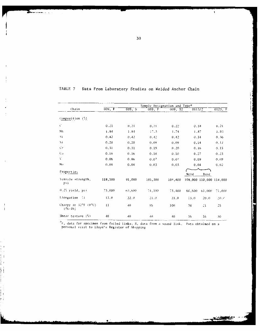
30
TABLE 7 Data From Laboratory Studies on Welded Anchor Chain
Sample Designation and TypeaChain 009, F 009, S 009, F 009, S2 0113/2 0123, F
Composit ion (%)
C 0.21 0.21 0.21 (.22 0.18 0.21
Mn 1.84 1.84 17.3 1.74 1.87 1 .93
Si 0.42 0.42 0.42 0.42 0.34 O.36
Ni 0.20 0.20 0.09 0.09 0.14 0.12
Cr 0.31 0.31 0.19 0.20 0.16 O.15
CU 0.16 0.16 0.10 0.10 0.27 0.23
V 0.06 0.06 0.07 0.07 0.09 0.09
Mo 0.04 0.04 0.03 0,03 0.04 0.02
Properties Wl~sWeld Base
lensile strength, 118,500 91,000 105,300 1OA,400 108,000 110,000 114,000psi
0.2. yield, psi 73,000 63,600 74,100 73,400 60,500 61,000 71,000
Cilongation U.) 13.0 22.0 21.0 21.0 13.0 20.0 20.0
Charpy at 320F (0CC) 11 40 95 100 38 21 25
(ft-lb)
Shear texture (%) 40 40 .0 40 35 35 30
aF, data for specimen from failed links; S, data from a sound link. Data obtained on apersonal visit to Lloyd's Register of Shipping
1. A 2-3/8 in.-diametcr I i i ., : i h the center of a0.4 in.-deep indentation in the I iiik ,- ,, J trming the link tomeet the stud. The strain associated ith the indentation caused acrack, up to 0.9 in.-deep, to form in the huat-affected zone (HtA:)of the butt weld in the link immediately above the stud. Thatcrack, which occurred before heat treatment, grew in service untilbrittle fracture took place.
2. Two links in a 3-1/4 in. chain broke in a brittle manner.In both cases the fractures occurred at two positions-in the vicinityof the flash-butt weld and transversely at the opposite sides of bothlinks. The fractures near the butt weld took place in the HAZ duringmanufacturing, and that area exhibited a coarse-grained, microstructurewith a ferrite network, Those characteristics, and crack initiation,resulted from gross overheating during welding. A sound link from thechain showed no evidence of grain coarsening. The properties of thesound and failed links are those listed for Samples 0009 in Table 7.
The sound links, with a uniformly fine-grained structure, hadacceptable mechanical properties. However, specimens from the twofailed links gave test values below the required levels of 17 percentelongation in tension and 43 ft.-lb. in V-notch Charpy tests at 32°F(O°C). The parent metal of those links was fine-grained, but oneexhibited a partially hardened structure containing bainite. The lattercharacteristic was considered responsible for the poor mechanicalproperties. Renormalizing did not eliminate the bainite or improvethe Charpy properties, but a subsequent tempering treatment wasbeneficial. Later studies on other links indicated that normalizingand tempering did not improve the properties of across-the-weldspecimens.
3. Three separate 3-1/4 in. chain links that had been rejectedfor service after magnetic-particle inspection were also examined. Thestudy, showed that inadequate gripping of the bars during flash weldingproduced folds or laps on the surface of the bars. Specimens takenfrom the base metal of the links, Sample 0113 in Table 7, had satisfactorytensile properties but unusually poor Charpy values. The across-the-weld specimen had poor tensile ductility. The lack of notch toughnesswas attributed to the high manganese content of the steel, whichcaused bainite to form in segregated areas. This experience confirmsthe opinion that tempering after normalizing is desirable.
4. Another 3-1/4 in. diameter chain link, for a drilling rig,with defects on both sides of the flash-butt weld, was also examined(Sample 0123 in Table 7). The Charpy properties of the parent metal onthe side opposite the weld were poor. That deficiency was attributedto the presence of patches of hainite in the microstructures resultingfrom a high manganese content.
32
Doerschuk, et al. (1977) evaluated the properties of somesamples of 4-3/4 in. flash-welded alloy steel stud-link chain.The commercial producers of the four samples were not required to fol-low the technical guidelines of the interim specification availableat that time, but their manufacturing practices were judged to bein close accord with those guidelines.
Table 8 lists the steel composition of the samples fromflash-welded anchor chain. Samples A and C meet the chemistrylimits for standard AISI 1330 steel. Samples B and D contain vanadiumand have carbon levels too low for that standard grade.
All of the samples met the bend test described in MIL-C-24573.None of the chain specimens broke in or near the flash weld. Theresults of other tests on samples taken from the chain are summarizedin Table 9. Comparing those values with the ones required by thecurrent MIL specification leads to the following comments:
* Sample C - slightly oversized but met all other requirements.* Sample B - gave a breaking load 3.7 percent below required
level but met other requirements.* Sample A - slightly undersized, narrowly failed breaking-
load and yield-strength requirements; met otherrequirements.
* Sample D - failed to meet required yield-strength andCharpy value for specimens taken near weld; metother requirements.
Since chain samples A and D had yield strengths below the required levelof 68,000 psi, it may be well to remember that Board of Trade rulesspecify a minimum ultimate strength, not a minimum yield strength(Celander, 1972).
The investigators also conducted metallographic studies onsamples taken from the chain. They found that the fillet weld be-tween the stud and link of Sample C was of poor quality; poor beadcontour, cracks, and regions of lack of fusion were detected. Somesmall cracks were found in Sample D near the flash weld and adjacentto the pressed-in stud. (This defect appar-citly resembles one ofthose found in laboratory studies by Lloyd's Register and describedabove.) Some bainite was present in banded (segregated) areas ofSample B. The microstructure of Sample C indicated that it had beenquenched and tempered, not normalized as required by the currentspecification.
The investigators concluded that flash-welded 4-3/4 in. anchorchain can be manufactured by existing commercial interests inaccordance with the interim specification (Doerschuk, et al., 1977).

33
0 0) 0 0
0D 0 0 0u
01 0 C 0 0
M ~ J 0 0- D C 0 '
-4u u * C; '1
.14* .14 0D C-D0E z
CiI04 0 0; 0C
0
tr (N It 0Q) - 00 co Lf)
-4 -40- -4
cdI 1-4
(-4 0 0 0
to w -4 4
4~J -u It r- 4~
.,-1 $-4-
o 0 X 4J X ~ 4-) H %
0~ 0 -u -
o 4 4-J- ~~
00
-let

34
TABLE 9 Data From Tests on Triplets of 4-3/4 In. Flash-WeldedAlloy Steel Chain
Sample Designation and Diameter; in.(mm)
Chain Specifications A, 4.73(120.0) B, 4.75(120.5) C, 5.2(132.0) D, 4.73(120.0)
Proof load, million lb. 1.7 1.7 1.7 1.7
Stretch (1) 0.00 2.01 0.23 0.39
Breaking load, 2 .5 40 a 2 .4 55 a 3.110 2.570million lb.
Tensile properties
Ultimate strength, 100,800 94,300 102,000 92,300psi
0.2% yield strength, 67,700 69,500 70,600 61,200psi
Reduction in area 66.1 68.8 64.6 70.0(%)
Brinell hardness
At mid-radius 199 192 201 185
0.1" below surface 187 181 269 188
Charpy V-notch at 32'F(0 OC)
Near ,jeld (ft-lb)b 45 52 65 26d
Base metal (ft-lb)c 53 122 107 127
Shear area
Near weld (%)b 50 57 62 44
Base metal (%)c 45 90 81 91
aMll-C-24573fShip) specifies a minimum breaking load of 2,550,000 lb.Averages for two specimens..Averages for three specimens.This value is below the minimum value of 36 ft-lb specified in MIL-C-24573(Ship).The individual values were 14.5 and 37 ft-lb.From Doerschuk, et al., 197'.
35
REFERENCES
American Society for Metals. 1971. "Flash and Fraction Welding."In Metals Handbook, Vol. 6, 8th Ed., pp. 485-518.
Brown, P. and R. Landers. 1957. NAVSHIPS Report No. 373-12(981),(July 1).
Buckle, A.K. 1980. "Ten Year Review of Defects and Failures in LargeShips' Anchoring and Mooring Equipment." Preprint C46 forConference on Mooring Large Ships Over 150,000 dwt, London,December 5, 1979. Accepted for publication in Marine Eng.(C), Vol. 92.
CASREPT Data Retrieval EIR TM03 NAVSEA 5141. 1979. In three parts:710101 to 741231 (50 pp.); 750101 to 751231 (22 pp.); 760101 to791024 (62 pp.). U.S. Navy Ships Parts Control Center, Mechanics-burg, Pa., (October 30).
Celander, I. 1972. "Preload Influence on Fatigue Characteristics ofChain Cable Exposed to Salt Weather and Atmosphere Conditions."Presented at Offshore Technology Conference, paper OTC 1578.
Doerschuk, D.C., R.J. Eiber, and T.P. Groeneveld. 1977. "LaboratoryEvaluation of 4-3/4" Flash Welded Alloy Steel Stud Link AnchorChain." Final report on MIPR No. N002476 MP6626M, 60 pp., (August).
Jamieson, F.L. and R.A. Wright. 1975. "Failures in Lifting Equipment,"In Metals Handbook, Vol. 10, 8th Ed., American Society for Metals,pp. 455-467.
Japanese Association for Prevention of Sea Casualties. 1976. "Investi-gation into Anchoring of Large Ships." (Not seen; cited inBuckle, 1980.)
Hauser, D. 1978. "Weldir of Railroad Rails-A Literature and IndustrySurvey." In Special Technical Publication 644. American Societyfor Testing and Materials, Philadelphia, Pa.
Military Specification MIL-C-24573(Ship). 1978. "Chain, 4-3/4 InchStud Link, Anchor, Steel, Flash Butt Welded," (May 15).
Stern, I.L. and M.F. Wheatcroft. 1978. "Toward Improving the Reliabilityof Anchor Chain and Accessories." Presented at 10th OffshoreTechnology Conference, Houston, Texas. Paper number 3206, (July).
ago

Chapter 6
DIE LOCK- AND FLASH-WELDED CHAIN EXPERIENCE
ANALYSIS PROCEDURE
The records and statements of operators described below forexperience with die lock and flash-welded chain were reviewed andclassified to determine recognizable patterns and feelings ofsatisfaction or dissatisfaction on the part of commercial and Navyship operating personnel. The design of chain links, wildcats, andstorage systems was also reviewed. An analysis was made, and conclu-sions were drawn from the results of these reviews.
U.S. NAVY DIE LOCK CHAIN SERVICE EXPERIENCE
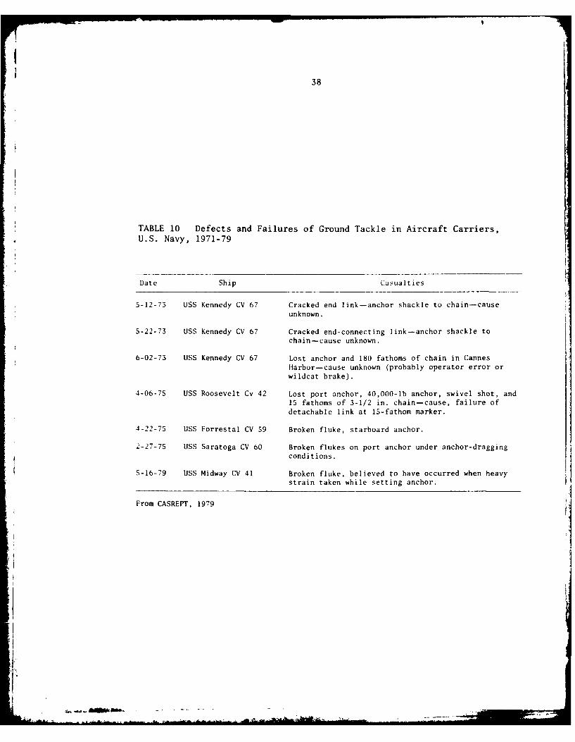
Aircraft-Carrier Casualties
Records before 1971 are not available or are not completelyreliable. The casualty reporting (CASREPT) data from the Navy for theperiod 1971-79 (CASREPT, 1979) appear substantially complete andreliable. CASREPT data for aircraft carriers (1971-79) were examinedfirst and are summarized in Table 10. Two end-connecting links werefound to be cracked, presumably during a routine examination. Therewas no loss of other ground tackle. There was one instance of loss ofanchor and 180 fathoms of chain, "cause unknown." This casualty is typicalof either operator error or failure of the wildcat braking system. Therewas one instance of loss of anchor and 15 fathoms of chain because of afailure of a detachable link. There were three failures of anchorflukes under heavy strain.
There were no cases reported of failure of a die lock chainlink.
Medium-Ship Ground-Tackle Casualties
Review was made of the 1971-79 CASREPT data for medium ships.In two ships under routine inspection, cracked or bent anchor oranchor-bending shackles were found. There were four cases of lost(later recovered) anchors and chains that occurred during the severedrop tests routinely conducted by the Navy Board of Inspection andSurvey. In all four cases, the casualty resulted from failure of thewildcat brake. In one case, the anchor shank was broken when theanchor dragged in high seas. The details are given in Table 11.
There were no cases reported of failure of a die lock chainlink.
37
___ING PA&GE BJ.Jhg-NO MID
38
TABLE 10 Defects and Failures of Ground Tackle in Aircraft Carriers,U.S. Navy, 1971-79
Date Ship Casualties
5-12-73 USS Kennedy CV 67 Cracked end link-anchor shackle to chain-causeunknown.
5-22-73 USS Kennedy CV 67 Cracked end-connecting link-anchor shackle tochain-cause unknown.
6-02-73 USS Kennedy CV 67 Lost anchor and 180 fathoms of chain in Cannes
Harbor-cause unknown (probably operator error orwildcat brake).
4-06-75 USS Roosevelt Cv 42 Lost port anchor, 40,000-lb anchor, swivel shot, and15 fathoms of 3-1/2 in. chain-cause, failure ofdetachable link at 15-fathom marker.
4-22-75 USS Forrestal CV 59 Broken fluke, starboard anchor.
2-27-75 USS Saratoga CV 60 Broken flukes on port anchor under anchor-draggingconditions.
5-16-79 USS Midway CV 41 Broken fluke, believed to have occurred when heavy
strain taken while setting anchor.
From CASREPT, 1979
--... ......---
39
TABLE 11 Defects and Failures of Ground Tackle in Medium SizedShips, U.S. Navy, 1971-79
Date Ship Casualty
5-09-74 USS Detroit AOL 4 Sprung anchor shackle-bent pin.
5-12-76 USS Kilauea AE 26 Lost anchor and 60 fathoms in 70 fathoms waterduring Insurv trials. Anchor and chain allowedto run free, then wildcat brake applied.Parted connecting shackle.
3-22-79 USS Ashtabula AO 51 Lost anchor and chain during Insurv test.Wildcat brake linings faulty,
5-07-76 USS Kawishiwi AO 146 Lost anchor and chain during drop test.Wildcat brake failed.
3-29-77 USS Ponchatoula AO 148 Lost anchor and chain during anchor wildcat testby Insurv. Brake failure. Chain ran free.
1-28-79 USS Seattle AOE 3 Anchor sank broken near crown, caused bydragging anchor in heavy seas during recoveryto get underway to prevent grounding,
7-14-77 USS Detroit AOE 4 Cracked bending link to anchor; one shot foundduring overhaul not to meet specifications.
From CASREPT, 1979.
I-

40
Destroyer Ground-Tackle Casualties
An analysis was next made of the ground-tackle casualties
reported for destroyers. A chart classifying all destroyer casualties
during the period 1971-79 is given as Table 12. There were eleven
CASREPT documents reporting ground tackle out of specification during
routine overhaul examinations. There were seven failures of detachable
links and seven failures of anchors (mostly under heavy load).
There were no cases reported of failure of a die lock chain
link.
TABLE 12 Types of Failure of Common Link in Destroyers, U.S. Navy1971-79
Out of Specification Detachable Link Anchor
DDG 4 DDG 35 DDG 8
DDG 5 DD 742 DDG 40DDG 32 DD 847 DD 868DD 708 DD 864 DD 880
DD 776 DD 878 DD 940
DD 805 DD 944 DD 883DD 819 DD 945 DD 950DD 820DD 763DD 785DD 863
Total 11 7 7
From CASREPT, 1979
FLASH-WELDED CHAIN EXPERIENCE
Flash-welded chain service data were not available in a CASREPT
form. An October 29, 1979, American Bureau of Shipping report gives
a summary of failure data collected from survey reports for 1965-68
and 1973-79. Table 13 shows the results of these reports. It is
apparent that failure of connecting links dominated the casualty reports.
Fifty percent of all failures (excluding anchor failures) were connecting-
link failures. Twenty-seven percent were common-link failures. In the
ABS documents, the chief surveyor reported that during the period
1973-77, three big (larger than 4 in.) chain failures were obser-;ed.
One failure occurred in the radius of an integral stud (near the heat
affected zone of the flash weld); another failure occurred at the

41
fifth link inboard while the ship was at anchor in heavy weather;another link was elongated and cracked, indicating significant stressing.In another case, the chain suffered seven bent links with no mention ofcracking.
TABLE 13 Number of Ground-Tackle Failures Reported in Merchant Ships,1965-77, by Type of Equipment
Anchor Connecting Link Common Link Bitter Enda
94 178 96 82
aMost bitter-end fialures were related to windlass malfunction or to
operator error.From American Bureau of Shipping, October 29, 1979.
A review of the experience of operating personnel did not providecrisp and definitive information. Few people had experience withboth die lock and flash-welded chain. All confirmed the urgent necessityfor reliable ground tackle.
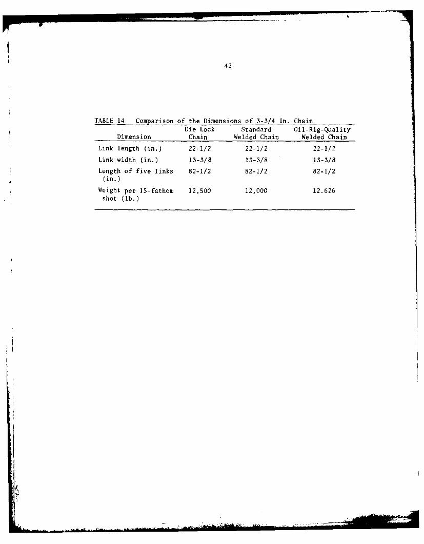
Design considerations include not only strength and resistance tofailure of the chain links, but also resistance to strain. Elongationand distortion of the links beyond specification result in poor fitof the links in the whelps of the wildcat. With the chain out of thecontrol of the wildcat, loss of ground tackle and even disaster canoccur. A comparison of the dimensions of the chain as shown in theU.S. manufacturer's catalog is presented in Table 14. From the abovetable it can be seen that the lengths and widths of the individual chainlinks are identical and that the weights of the 15-fathom shots areessentially the same, and therefore, the use of such welded chainshould be compatible with existing wildcats and associated systems.There is also a design parameter relatiog to stacking and payoutwithout kinking; this is important in preventing overstressing andmaterial damage and loss. The stud is obviously the key in the preventionof kinking. The size and shape of the holes are also important.
The review of service experience available would indicate that thedie lock chain has been satisfactory and reliable in naval service, andthat there has been little U.S. Navy experience with welded chain.
4 .
42
TABLE 14 Comparison of the Dimensions of 3-3/4 In. ChainDie Lock Standard Oil-Rig-Quality
Dimension Chain Welded Chain Welded Chain
Link length (in.) 22-1/2 22-1/2 22-1/2
Link width (in.) 13-3/8 13-3/8 13-3/8
Length of five links 82-1/2 82-1/2 82-1/2(in.)
Weight per 15-fathom 12,500 12,000 12.626shot (lb.)
IF
Chapter 7
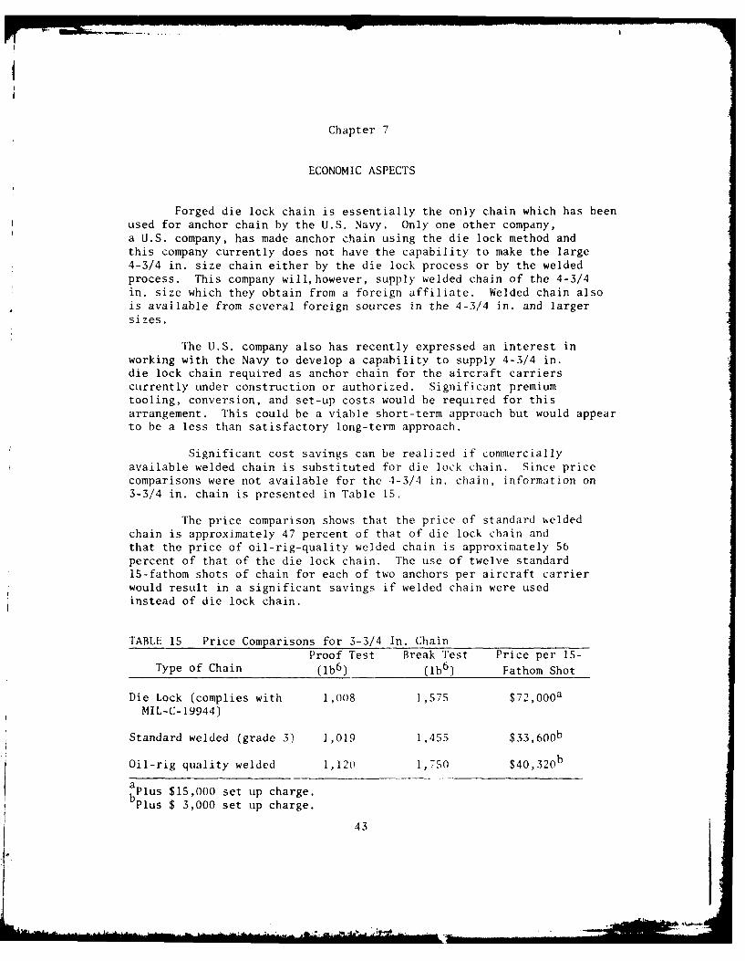
ECONOMIC ASPECTS
Forged die lock chain is essentially the only chain which has beenused for anchor chain by the U.S. Navy. Only one other company,a U.S. company, has made anchor chain using the die lock method andthis company currently does not have the capability to make the large4-3/4 in. size chain either by the die lock process or by the weldedprocess. This company will, however, supply welded chain of the 4-3/4in. size which they obtain from a foreign affiliate. Welded chain alsois available from several foreign sources in the 4-3/4 in. and largersizes.
The U.S. company also has recently expressed an interest inworking with the Navy to develop a capability to supply 4-3/4 in.die lock chain required as anchor chain for the aircraft carrierscurrently under construction or authorized. Significant premiumtooling, conversion, and set-up costs would be required for thisarrangement. This could be a viable short-term approach but would appearto be a less than satisfactory long-term approach.
Significant cost savings can be realized if commerciallyavailable welded chain is substituted for die lock chain. Since pricecomparisons were not available for the 4-3/4 in. chain, information on3-3/4 in. chain is presented in Table 15.
The price comparison shows that the price of standard weldedchain is approximately 47 percent of that of die lock chain andthat the price of oil-rig-quality welded chain is approximately 56percent of that of the die lock chain. The use of twelve standard15-fathom shots of chain for each of two anchors per aircraft carrierwould result in a significant savings if welded chain were usedinstead of die lock chain.
TABLE 15 Price Comparisons for 3-3/4 In. ChainProof Test Break Test Price per 15-
Type of Chain (Ib6) (b 6) Fathom Shot
Die Lock (complies with 1,008 1,575 $72,000 a
MIL-C-19944)
Standard welded (grade 3) 1,019 1,455 $33,600 b
Oil-rig quality welded 1,120 1,750 $40,320 b
aPlus $15,000 set up charge.Plus $ 3,000 set up charge.
43
44
As indicated earlier in Chapter 6 (Table 14) the physicaldimensions of the 3-3/4 in. chain are essentially the same for the dielock chain, the standard welded chain, and the oil-rig-quality weldedchain.
Although the physical dimensions and price comparisons shownin Tables 14 and 15 are for 3-3/4 in. chain rather than for 4-3/4 in.chain which is the subject of this report, it is reasonable to expectthat the comparisons presented are representative of what would beexpected for the larger size chain and that significant cost savingsare available if welded chain is used instead of die lock chain.
At the present time the large size chain is not manufactured inthe U.S. but it is manufactured in several other countries usingthe welded process. Assuming that all other considerations aresatisfactorily met, substitution of welded chain commercially availablefrom several world sources would be the most economical approach forfuture procurements of anchor chain.

THE NATIONAL ACADEMY OF SCIENCES was established in 1863 by Act ofCongress as a private, non-profit, self-governing membership corporation for the fur-therance of science and technology, required to advise the federal government uponrequest within its fields of competence. Under its corporate charter the Academy estab-lished the National Research Council in 1916, the National Academy of Engineering in1964, and the Institute of Medicine in 1970.
THE NATIONAL ACADEMY OF ENGINEERING was founded in 1964 as a non-profit membership institution, by action of the National Academy of Sciences underthe authority of its congressional charter of 1863 establishing it as a private, self-governing corporation to further science and technology and to advise the federal gov-ernment. The two Academies share those purposes in their fields.
THE NATIONAL RESEARCH COUNCIL was established in 1916 by the NationalAcademy of Sciences to associate the broad community of science and technology withthe Academy's purposes of furthering knowledge and of advising the federal govern-ment. The Council operates in accordance with general policies determined by theAcademy by authority of its Congressional charter of 1863 as a non-profit, self-governingmembership corporation. Administered jointly by the National Academy of Sciences,the National Academy of Engineering, and the Institute of Medicine (all three of whichoperate under the charter of the National Academy of Sciences), the Council is theirprincipal agency for the conduct of their services to the government and the scientificand engineering communities.
THE COMMISSION ON SOCIOTECHNICAL SYSTEMS is one of the major com-ponents of the National Research Council and has general responsibility for andcognizance over those program areas concerned with physical, technological, and in-dustrial systems that are or may he deployed in the public or private sector to servesocietal needs.
THE NATIONAL MATERIALS ADVISORY BOARD is a unit of the Commission onSociotechnical Systems of the National Research Council. Organized in 1951 as theMetallurgical Advisory Board, through a series of changes and expansion of scope, itbecame the Materials Advisory Board and, in January 1969, the National MaterialsAdvisory Board. In consonance with the scope of the two Academies, the general purposeof the Board is the advancement of materials science and engineering, in the nationalinterest. The Board fulfills its purpose by: providing advice and assistance, on request, togovernment agencies and to private organizations on matters of materials science andtechnology affecting the national interest; focusing attention on the materials aspectsof national problems and opportunities, both technical and nontechnical in nature, andmaking appropriate recommendations as to the solution of such problems and theexploitation of these opportunities; performing studies and critical analyses on mate-rials problems of a national scope, recommending approaches to the solution of theseproblems, and providing continuing guidance in the implementation of resultingactivities; identifying problems in the interactions of materials disciplines with othertechnical functions, and defining approaches for the effective utilization of materialstechnologies; cooperating in the development of advanced educational concepts andapproaches in the materials disciplines; communicating and disseminating informationon Board activities and related national concerns; promoting cooperation with andamong the materials-related professional societies; maintaining an awareness of trendsand significant advances in materials technology, in order to call attention to opportuni-ties and possible roadblocks, and their implications for other fields, and recognizing andpromoting the development and application of advanced concepts in materials and ma-terials processes.
