narrowband interference reduction technique in impulse
TRANSCRIPT

BIKRAMADITYA DAS et. al.: NARROWBAND INTERFERENCE REDUCTION TECHNIQUE IN IMPULSE RADIO (IR) UWB COMMUNICATION SYSTEM COEXISTING IN WPAN
DOI: 10.21917/ijct.2012.0067AND UNDERWATER ENVIRONMENT
478
NARROWBAND INTERFERENCE REDUCTION TECHNIQUE IN IMPULSE RADIO
(IR) UWB COMMUNICATION SYSTEM COEXISTING IN WPAN AND
UNDERWATER ENVIRONMENT
Bikramaditya Das1, Ch. Sasmita Das
2, Susmita Das
3, Bidyadhar Subudhi
4 and Bibhuti Bhusan Pati
5
1,5Department of Electrical Engineering, Veer Surendra Sai University of Technology, India
E-mail: [email protected] and
2,3,4Department of Electrical Engineering, National Institute of Technology Rourkela, India
E-mail: [email protected] and
Abstract
The Impulse Radio based Ultra Wideband (IR-UWB) system transmits
data by sending pulses, each with very small time duration followed by
pauses that are approximately two hundred times that length. Rake
receiver improves system performance by equalizing signals from
different paths. This enables the use of Rake receiver techniques in
UWB systems. For high data rate ultra-wideband communication
system, performance comparison of ARake, PRake and SRake
receivers are attempted. Although UWB communication offers a
promising solution in an increasingly overcrowded frequency
spectrum, mutual interference due to coexistence with other spectrally
overlapping wireless system degrades the performance of both
systems. The narrow band systems may cause interference with UWB
devices as it is having very low transmission power and the large
bandwidth. So it may jam the UWB receiver completely degrading
their performance. Rake receiver alone fails to perform in such
condition. A hybrid SRAKE-MMSE time domain equalizer is
proposed to overcome this by taking into account both the effect of the
number of rake fingers and equalizer taps. This scheme selects the
first strongest multipath components and combines them using a
SRake receiver based on the minimum mean square error (MMSE)
criterion. It also combats inter-symbol interference by considering the
same advantages. Study on non-line of sight indoor channel models
illustrates that bit error rate performance of UWB SRAKE-MMSE
(both LE and DFE types) improves for CM3 model with smaller
spread compared to CM4 channel model cancelling out the
narrowband interference. A modified UWB channel model is
proposed using the Rician distribution for underwater
communication. Again BER performance of the proposed receiver is
compared with traditional receiver technique for the underwater
UWB LOS channel model.
Keywords:
RAKE-MMSE, LE, DFE, IEEE 802.15.3a, Underwater, NBI
1. INTRODUCTION
Ultra-wideband (UWB) radio is an emerging technology in
WPAN wireless system that has attracted a great deal of interest
from academia, industries, and global standardization bodies.
The IEEE 802.15.3a (TG3a) and IEEE 802.15.4a (TG4a) are two
task groups (TGs) within 802.15 working group (WG) that
develop their standards based on UWB technology. UWB
technology has been around since 1960, when it was mainly
used for radar and military applications. Recent advances in
silicon process and switching speeds are moving it into the
commercial domain. One of the most promising commercial
application areas for UWB technology is the very high data rate
wireless connectivity of different home electronic devices at low
cost and low power consumption. Ultra-wideband technology
offers a solution for sharing the bandwidth resource and physical
size requirements of next-generation consumer electronic
devices. In addition, UWB promises low susceptibility to
multipath fading, high transmission security and simple design.
A traditional UWB technology is based on single band systems
employing carrier free or impulse radio communications.
Impulse radio (IR) refers to the generation of a series of impulse
like waveforms, each of duration in the hundreds of picoseconds
[1], [2] and [7]. This type of transmission does not require the
use of additional carrier modulation and is a baseband signal
approach. UWB technology provides high data rate with low
power spectral density due to modulation of extremely short
pulses within 3.1 to 10.6 GHz [5]. The very low transmission
power and the large bandwidth enable an UWB system to co-
exist with narrowband communication [3] systems illustrated in
Fig.1.
Fig.1. Spectrum of UWB and existing narrowband systems
Although UWB communication offers a promising solution
in an increasingly overcrowded frequency spectrum, mutual
interference due to coexistence with other spectrally overlapping
wireless system degrades the performance of both systems [4].
The interference caused may jam the UWB receiver completely.
According to Electromagnetic Compatibility (EMC) reports
submitted to FCC [24], the narrowband interferences (NBI)
expected by the UWB receivers are computer motherboard of
emission level 42.7 dBm at 1.9 GHz, IEEE 802.11b at centre
frequency 2.4 GHz, network interface card (NIC) of emission
level 49.8 dBm at 3.75 GHz, LAN switch of 44.3 dBm at 3.75
GHz, peripheral component interconnect (PCI) card for a

ISSN: 2229-6948(ONLINE) ICTACT JOURNAL ON COMMUNICATION TECHNOLOGY, MARCH 2012, VOLUME: 03, ISSUE: 01
479
personal computer 3.75 GHz and IEEE 802.11a (WLAN system)
at centre frequency 5.25 GHz etc. [3]. Study of impact of NBI
and suppression of NBI is one of the important issues associated
with UWB applications [16], [18] and [19] and [12]. Performance
enhancement by employing effective NBI mitigation techniques
are discussed in this research work [20].
Section 2 introduces the principle of UWB Rake receiver
considering its importance in UWB system. In section 3, UWB
Rake receiver structure is analyzed in the presence of NBI.
Simulation results for performance analysis of UWB Rake
receiver and performance degradation of UWB SRake receiver
in presence of NBI are presented in section 4 and 5 respectively.
Section 6 explains the performance of UWB SRAKE-MMSE
receiver and section 7 investigates the suppression of interference
by using the same. Simulation results are presented in section 8.
The conclusion is presented in section 9.
2. UWB RAKE RECEIVER STRUCTURE
The robustness of UWB signals to multipath fading [3] is
due to their fine delay resolution, which leads to a high diversity
order once combined with a Rake receiver. Rake receivers are
used in time-hopping impulse radio systems and direct sequence
spread spectrum systems for matched filtering of the received
signal [2], [10] and [11]. The receiver structure consists of a
matched filter that is matched to the transmitted waveform that
represents one symbol and a tapped delay line that matches the
channel impulse response [9] and [14]. It is also possible to
implement this structure as a number of correlators that are
sampled at the delays related to specific number of multipath
components; each of those correlators is known as rake finger.
Based upon the Rake receivers are three types. The All-Rake
(ARake) receiver captures all most all the energy carried by a
very large number of different multipath signals [8] and [13].
To reduce the rake complexity, a partial combining (called
PRake) is used as partial combining of the energy, which
combines the first arriving paths out of the available resolved
multipath components. Selective combining (called SRake) is a
suboptimum Rake receiver, which combines the energy
selectively carried out by the strongest multipath components. A
UWB Rake receiver structure is shown in Fig.2.
For a single user system, the continuous transmitted data
stream is represented as [13]
( ) ( ). ( . )s
k
s t d k p t k T
(1)
where, d(k) are stationary uncorrelated BPSK data and Ts is the
symbol duration. The UWB pulse p(t) has duration Tuwb (Tuwb
< Ts).
The channel impulse response is given by [6] and [22]
0
( ) . ( )M
i i
i
h t h t
(2)
M is the total number of paths in the channel. The received
signal first passes through the receiver filter matched to the
transmitted pulse and is given by,
( ) ( )* ( )* ( ) ( )* ( )
( ) . ( . ) ( )i s i
k i
r t s t h t p t n t p t
d k h m t k T n t
(3)
where, p(-t) represents the receiver matched filter and n(t) is the
Additive White Gaussian Noise (AWGN) with zero mean and
variance N0/2. Also,
( ) ( )* (- ) m t p t p t and ˆ( ) ( )* ( )n t n t p t
Combining the channel response with the transmitter pulse
shape and the matched filter,
~
0
( ) ( ) * ( ) * ( ) . ( ).M
i i
i
h t p t h t p t h m t
(4)
The received signal sampled at the lth
rake finger in the nth
data symbol interval is given by,
~
' '
0 0. . .s l s l
k
v nT t h n k T t d k
(5)
where, l is the delay time corresponding to the lth rake finger
and is an integer multiple of Tm. Parameter t0 corresponds to a
time offset and is used to obtain the best sampling time. For the
following analysis t0 will be set to zero. The Rake combiner
output at time t = n.Ts is,
' '
1 1
[ ] . . . . .L L
l s l l s l
l l
y n v nT n nT
(6)
Fig.2. UWB Rake receiver structure
2
1 1
r(t) {d(k)} p(t) CHANNEL
(IEEE 802.15.3a) p(-t)
h(t) n(t)
DETECTOR
2
L L

BIKRAMADITYA DAS et. al.: NARROWBAND INTERFERENCE REDUCTION TECHNIQUE IN IMPULSE RADIO (IR) UWB COMMUNICATION SYSTEM COEXISTING IN WPAN
AND UNDERWATER ENVIRONMENT
480
Fig.3. UWB Rake receiver model in presence of NBI
3. UWB SRAKE RECEIVER IN PRESENCE OF
NBI
The working of UWB system in co-existence with other
narrowband systems over their large bandwidth is challenging
[12]. Thus, UWB systems must cope with these narrow band
interference (NBI) using their high processing gain. However,
due to very low transmission power, it is not sufficient to
suppress high levels of NBI are typically from nearby
narrowband radio systems using a bandwidth of up to a few
MHz In many cases, the power of NBI is a few tens of dBs
higher than both the signal and noise power. The narrowband
interference (NBI) signal is modelled as a traditional single
carrier BPSK modulated waveform, given by [14] and [16]
1 0 1 1( ) 2 cos( ) ( )k
p
i t P t g z t kT
(7)
where, Pl is average transmit power of the narrowband
waveform. 0=2f0 is carrier frequency of the narrowband
waveform. is the random phase of the carrier. {gk} are the
randomly modulated BPSK symbols where gk{}, T1 is the
symbol period, 1 is a random delay uniformly distributed in [0,
T1] and z(t) is the baseband wave form shape. UWB Rake
receiver model considering NBI is shown in Fig.3.
The received signal passes through the receiver filter
matched is given by [14]
r(t) = A(t) * h(t) * p(-t) + n(t) * p(-t) + i(t) * p(-t) (8)
Interference coexisting with the same system generates extra
signal which can’t be easily detected at the output. Rather by
coexisting with original pulse, it will decrease the performance of
receiver. If such interference is not properly suppressed, then this
will jam the receiver and the system performance degrades [12].
4. PERFORMANCE ANALYSIS OF RAKE
RECEIVERS IN IR-UWB SYSTEM
BER performance of Rake receiver in IR-UWB system is
observed through MATLAB simulation. Performance comparison
among ARake, SRake, and PRake receiver is carried out using
different IEEE UWB channel models [6] as shown in Fig.4.
ARake receiver provides better result than other two types of
Rake. Since a UWB signal has a very wide bandwidth, ARake
receiver combining all the paths of the incoming signal is
practically unfeasible. Therefore, SRake becomes the practical
choice. It is observed form Fig.4(a) that using the perfect channel
impulse response and estimating 8 number of rake fingers; ARake
provides best performance of gaining more than 4dB SNR over
the PRake receiver at BER = 10-3
. It is also found that SRake and
PRake have almost the same diversity order, and differs by less
than 2dB due to line of sight (LOS) channel medium.
Fig.4(a). BER performance of Rake receivers for CM1 model
Fig.4(b). BER performance of Rake receivers for CM2 model
In the analysis CM2 channel model, SRake performance
approaches almost the same performance level as ARake. SRake
receiver provides 3dB SNR improvement at 10-2
BER floor over
the PRake as shown in Fig.4(b).
i(t)
2
1 1
r(t) {d(k)} p(t) CHANNEL
(IEEE 802.15.3a) p(-t)
h(t) n(t)
DETECTOR
2
L L
INTERFERENCE

ISSN: 2229-6948(ONLINE) ICTACT JOURNAL ON COMMUNICATION TECHNOLOGY, MARCH 2012, VOLUME: 03, ISSUE: 01
481
Fig.4(c). BER performance of Rake receivers for CM3 model
Fig.4(d). BER performance of Rake receivers for CM4 model
In Fig.4(c) showing SRake receiver performance, gain of
more than 4dB SNR over the PRake at BER=10-2
for NLOS
CM3 channel environment. Using CM4 channel model, for the
same simulation parameter SRake performs better as shown in
Fig.4(d). A SNR gain of more than 5dB is observed on 10-2
BER
floor for SRake. At low SNR’s the system noise is more and
hence the system degradation is noticed. More signal energy
capture is required to overcome it. This can be achieved by
increasing the numbers of rake fingers in Rake receiver
structure.
5. STUDY OF PERFORMANCE DEGRADATION
OF UWB SYSTEM IN PRESENCE OF NBI
SRake receiver in UWB system performance in absence and
presence of NBI is studied and found that NBI deteriorates the
system performance. In this study SRake with both 3 and 5 rake
fingers is considered. An NBI with signal to interference ratio
(SIR) of -20dB is added to the UWB channel model.
Fig.5. Performance of SRake receiver for CM1 channel model
Fig.6. Performance of SRake receiver for CM2 channel model
Fig.7. Performance of SRake receiver for CM3 channel model

BIKRAMADITYA DAS et. al.: NARROWBAND INTERFERENCE REDUCTION TECHNIQUE IN IMPULSE RADIO (IR) UWB COMMUNICATION SYSTEM COEXISTING IN WPAN
AND UNDERWATER ENVIRONMENT
482
Fig.8. Performance of SRake receiver for CM4 channel model
However, as discussed before with increase in rake fingers
the performance of SRake receiver increases. When the number
of rake fingers is increased to 5, similar degradation in
performance is noticed in both CM1 LOS channel medium and
in CM2 NLOS channel medium as shown in Fig.6. As shown in
Fig.7 for CM3 channel model, at SNR=20dB, UWB SRake
receiver bit error rate (BER) passes from 1.2 x 10⁻²
to 0.95 x 10⁻²
for 3 number of rake fingers and from 0.7 x 10⁻²
to 0.44 x 10⁻¹
for 5 number of rake fingers under the effect of NBI. The
performance of SRake receiver in presence of NBI is almost flat
above 10-1
BER floor. The receiver structure cannot and hence
deteriorates. So it is concluded as the multipath is reasonably
high for CM3 and CM4 channel models, Rake receiver structure
performance fails to eliminate NBI alone.
6. UWB SRAKE-MMSE RECEIVER STRUCTURE
This was achieved using Eigen value decomposition model
for a hybrid SRAKE-MMSE receiver structure for high data rate
UWB system is studied by the advantages of both rake fingers
and equalizer taps. A major advantage of MMSE scheme
relative to other interference suppression scheme is that explicit
knowledge of interference parameter is not required [15] and
[16].
The receiver structure is illustrated in Fig.9 and consists in a
SRake receiver followed by a linear MMSE equalizer. The
received signal first passes through the receiver filter matched to
the transmitted pulse. The output of the receiver filter is sampled
at each rake finger [14]. The minimum rake finger separation is
Tm=Ts/Nu, where Nu is chosen as the largest integer value that
would result in Tm spaced uncorrelated noise samples at the rake
fingers. For general selection combining, the rake fingers (β’s)
are selected as the largest L (L ≤ Nu) sampled signal at the
matched filter output within one symbol time period at time
instants 1 , l = 1, 2, ..., L.
For a minimum mean square error (MMSE) SRake receiver,
the conventional finger selection algorithm is to choose the paths
with highest signal-to-interference-plus-noise ratios (SINRs)
[17].
The noiseless received signal is given by Eq.(5). As derived
in section 2, Rake combiner output at time t = n.Ts is
' '
1 1
[ ] . . . .L L
l s l l s l
l l
y n v nT n nT
(9)
Assuming that the nth data bit is being detected, the MMSE
criterion consists in minimizing
2
( ) ( )E d n d n
(10)
where, ˆ( )d n is the equalizer output. From the Rake output signal,
the desired signal, the undesired ISI and the noise are
distinguished as,
1 11 1
1 1
1 1
1
( ) . ( ) . ( ) . (( ). ). ( )
ˆ. ( . )
L L
s
l k n l
L
s
l
y n h d n h n k T d k
n nT
(11)
where, the first term represents the desired output. The noise
samples at different fingers, ˆ( . )s ln nT , l = 1... L, are
uncorrelated and therefore independent, since the samples are
taken at approximately the multiples of the inverse of the
matched filter bandwidth. It is assumed that the channel has a
length of (n1+n2 +1).Ts. That is, there is pre-cursor ISI from the
subsequent n1 symbols and post-cursor ISI from the previous n2
symbols, and n1 and n2 are chosen large enough to include the
majority of the ISI effect [21] and [23]. Using Eq.(11), the Rake
output can be expressed now in a simple form as,
2
1
0
0
( ) . ( ) . ( ) ( ) [ ] ( )n
T
k
k nk
y n d n d n k n n n n n
(12)
where =[n1..0..n2] and d[n]=[d(n+n1)..d(n)..d(n-n2)]T.
Coefficient of k’s are obtained by matching Eq.(11) and
Eq.(12). The noise at Rake output is ~
'
1
( ) ( .Ts + )
L
l l
l
n n n n .
The output of the linear equalizer (LE) is obtained as
2
1
( ) .
k
T Tr
r k
d n c y n r c n c n
(13)
where c =[cK1 ...c0 ...cK2] contains the equalizer taps. Also
[n] = [T d[n+k1]… T
d[n]… T d[n-k2]]
T (14)
~ ~ ~
1 2... ...
T
n n n K n n n n K
(15)
The mean square error (MSE) of the equalizer,
2T TE d n c n c n
(16)
Eq.(16) is a quadratic function of the vector c, has a unique
minimum solution. Defining matrices R, p and N as,
R = E[[n]. T [n]] (17)
p = E[d(n). [n]] (18)
N = E[[n]. T[n]] (19)

ISSN: 2229-6948(ONLINE) ICTACT JOURNAL ON COMMUNICATION TECHNOLOGY, MARCH 2012, VOLUME: 03, ISSUE: 01
483
Fig.9. UWB SRAKE-MMSE receiver structure
The equalizer taps are given by
c = (R+N)-1
.p (20)
and the MMSE is
2 1
min ( ) .T
dJ p R N p (21)
2
2 [ ( ) ]d E d n
This Rake equalizer receiver will eliminate ISI as far as the
number of equalizer’s taps gives the degree of freedom required.
The equalizer output can be expressed as,
0
0
. ( ) . ( )
i
i
d n q d n q d n i w n
(22)
with qn = n.cn
The variance of w( n ) is,
2
1
2 2 2 01
1
. . 2
K L
i pw ni K l
Nc E
(23)
where Ep is the pulse energy. In the case of decision feedback
equalizer (DFE), assuming error free feedback, the input data
vector can be written in the form of
DFE[n] = [Td[n + k1]…T
d[n]d[n – 1]…dn-k2 (24)
7. UWB SRAKE-MMSE RECEIVER IN PRESENCE
OF NBI
A narrow band interference model, that is generally WLAN,
which coexists with UWB signal at the frequency 5.25 GHz as,
provided in Eq.(7). The received signal sampled at the lth rake
finger in the nth data symbol interval given by Eq.(7). The Rake
combiner output [14] at time t = n.Ts
' ' '
1 1 1
[ ] . . . . . .L L L
l s l l s l l s l
l l l
y n v nT i nT n nT
(25)
Fig.10. UWB RAKE-MMSE receiver structure with NBI
The received signal is sampled at pulse repetition frequency
after passing through the correlation receiver. The samples are
linearly combined using the MMSE criterion, so that weights are
effective to suppress the NBI [16]. The MMSE weight vector
c*is given by
c* = (Rs+Rl+RN)-1
.p (26)
where Rs, R1, RN are the autocorrelation of the signal, the NBI
and the noise respectively. So The MMSE can be mathematically
expressed as
2 1
min ( ) .T
d s l NJ p R R R p (27)
2
2 [ ( ) ]d E d n (28)
Thus, it is concluded that in the NBI suppression analysis
using SRAKE-MMSE receiver, the correlation between the
samples of the received signal plays the main role. Assuming
n(t) is not correlated to i(t) and has an impulsive auto-correlation,
Hence the NBI is modelled as single tone.
8. SIMULATION STUDY AND RESULTS
8.1 PERFORMANCE ANALYSIS OF SRAKE-
MMSE RECEIVER IN UWB SYSTEM
Performance of hybrid SRAKE-MMSE equalizer receiver for
high data rate UWB system is investigated through MATLAB
simulation. In the evaluation of receiver performance, high
multipath UWB propagation channel models, i.e. CM3 and CM4
are considered. In UWB SRAKE-MMSE receiver design,
selection of the number of rake fingers and the length of
equalizer taps play a main role. The rake fingers are regularly
positioned according to time channel spread and the number of
fingers [17].
The pulse shape adopted in the simulation study is taken as
the second derivative of the Gaussian pulse with pulse width
0.35 nsec. The root raised cosine (RRC) pulse with roll off factor
= 0.5 is used in the pulse-shaping filter. An oversampling
factor of eight is used for the root raised cosine (RRC) pulse
According to this sampling rate, time channel spread is chosen
equal to 100 for CM4 and 70 for CM3, this corresponds to
respectively 12 =100/8 and 9 = 70/8 transmitted symbols. This
choice enables to gather 99% of the channel energy. The
coherence bandwidths of CM3 and CM4 simulation are 10.6
MHz and 5.9 MHz respectively. The data rate is chosen to be
200 Mbps resulting in symbol duration of 5 nsec. The simulation
is performed at 100.8 GHz sampling rate. The rake finger
minimum time spacing is chosen as 0.1786 nsec, for Nu = 28.
p(t) UWB
CHANNEL
(IEEE 802.15.3a)
p(-t) SRAKE-MMSE
EQUALIZER
n(t) AWGN
i(t) NBI
{ d̂ (n)}
2
1 1
{d(n)} p(t) CHANNEL
(IEEE 802.15.3a) p(-t)
h(t) n(t)
MMSE
EQUALIZER
2
L L
BIKRAMADITYA DAS et. al.: NARROWBAND INTERFERENCE REDUCTION TECHNIQUE IN IMPULSE RADIO (IR) UWB COMMUNICATION SYSTEM COEXISTING IN WPAN
AND UNDERWATER ENVIRONMENT
484
Each channel is normalized prior to multiplying it by the
shadowing factor. The shadowing factor is also normalized to
have unit average value over all the 100 channel realizations.
The transmitter pulse shape has unit energy. The size of the
transmitted packets is equal to 2560 BPSK symbols including a
training sequence of length 500. CIR remains constant over the
time duration of packet. Table.1 provides all the simulation
parameter used for SRAKE-MMSE receiver. Performance of
UWB SRAKE-MMSE receiver varying length of equalizer taps
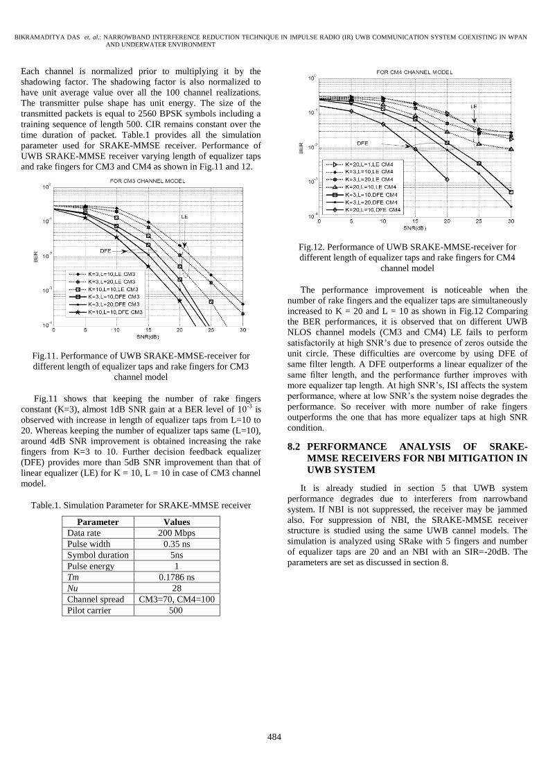
and rake fingers for CM3 and CM4 as shown in Fig.11 and 12.
Fig.11. Performance of UWB SRAKE-MMSE-receiver for
different length of equalizer taps and rake fingers for CM3
channel model
Fig.11 shows that keeping the number of rake fingers
constant (K=3), almost 1dB SNR gain at a BER level of 10-3
is
observed with increase in length of equalizer taps from L=10 to
20. Whereas keeping the number of equalizer taps same (L=10),
around 4dB SNR improvement is obtained increasing the rake
fingers from K=3 to 10. Further decision feedback equalizer
(DFE) provides more than 5dB SNR improvement than that of
linear equalizer (LE) for K = 10, L = 10 in case of CM3 channel
model.
Table.1. Simulation Parameter for SRAKE-MMSE receiver
Parameter Values
Data rate 200 Mbps
Pulse width 0.35 ns
Symbol duration 5ns
Pulse energy 1
Tm 0.1786 ns
Nu 28
Channel spread CM3=70, CM4=100
Pilot carrier 500
Fig.12. Performance of UWB SRAKE-MMSE-receiver for
different length of equalizer taps and rake fingers for CM4
channel model
The performance improvement is noticeable when the
number of rake fingers and the equalizer taps are simultaneously
increased to K = 20 and L = 10 as shown in Fig.12 Comparing
the BER performances, it is observed that on different UWB
NLOS channel models (CM3 and CM4) LE fails to perform
satisfactorily at high SNR’s due to presence of zeros outside the
unit circle. These difficulties are overcome by using DFE of
same filter length. A DFE outperforms a linear equalizer of the
same filter length, and the performance further improves with
more equalizer tap length. At high SNR’s, ISI affects the system
performance, where at low SNR’s the system noise degrades the
performance. So receiver with more number of rake fingers
outperforms the one that has more equalizer taps at high SNR
condition.
8.2 PERFORMANCE ANALYSIS OF SRAKE-
MMSE RECEIVERS FOR NBI MITIGATION IN
UWB SYSTEM
It is already studied in section 5 that UWB system
performance degrades due to interferers from narrowband
system. If NBI is not suppressed, the receiver may be jammed
also. For suppression of NBI, the SRAKE-MMSE receiver
structure is studied using the same UWB cannel models. The
simulation is analyzed using SRake with 5 fingers and number
of equalizer taps are 20 and an NBI with an SIR=-20dB. The
parameters are set as discussed in section 8.

ISSN: 2229-6948(ONLINE) ICTACT JOURNAL ON COMMUNICATION TECHNOLOGY, MARCH 2012, VOLUME: 03, ISSUE: 01
485
Fig.13. Performance of SRAKE-MMSE receiver with NBI for
CM1 channel model
Fig.14. Performance of SRAKE-MMSE receiver with NBI for
CM2 channel model
Fig.15. Performance of SRAKE-MMSE receiver with NBI for
CM3 channel model
Similar effects in performance are observed for CM3 and
CM4 models also. Table.2 describes the improvement in BER
level at SNR =20dB.
Fig.16. Performance of SRAKE-MMSE receiver with NBI for
CM4 channel model
Table.2. Improvement in BER level at SNR=20dB
Receiver
structure
UWB SRAKE-
MMSE
Receiver in
presence of
NBI
(SIR=-20dB)
UWB SRake
receive in
presence of
NBI
(SIR=-20dB)
UWB
Channel
models
BER BER
CM1 << 0.1 x 10⁻²
0.11 x 10⁻¹
CM2 0.4 x 10⁻²
0.36 x 10⁻¹
CM3 0.5 x 10⁻²
0.88 x 10⁻¹
CM4 0.12 x 10⁻¹
0.155 x 100
8.3 PERFORMANCE ANALYSIS OF SRAKE-
MMSE RECEIVERS FOR NBI MITIGATION IN
UNDERWATER MODIFIED UWB CHANNEL
MODEL
The speed of sound underwater is approximately 1500 m/s,
which provides a large propagation delays and motion-induced
Doppler effects. Phase and amplitude fluctuations may induce
high bit error probability. Interference is another phenomenon in
underwater acoustic networks, causing frequency-selective
fading in underwater channels. Research are carried out
assuming Rayleigh fading in nature, but it is observed that
Rayleigh fading exhibits better in terrestrial communication than
UWA communication [25]. According to Ray theory, the
number of Eigen rays reaching the receiver must be a Poisson
distribution with a mean value. A modified UWB S-V channel
model for underwater acoustic networks is proposed. In an
underwater acoustic channel, the communication frequency
range is inferior to 10 kHz. In short-range transmission, the
carrier frequency is 550 Hz in shallow water and 2 kHz in deep
water. The carrier frequency for long-range transmission is 1500
Hz. In all cases, the fractional bandwidth (fH − fL)/((fH + fL)/2)
BIKRAMADITYA DAS et. al.: NARROWBAND INTERFERENCE REDUCTION TECHNIQUE IN IMPULSE RADIO (IR) UWB COMMUNICATION SYSTEM COEXISTING IN WPAN
AND UNDERWATER ENVIRONMENT
486
is much greater than 0.20–0.25. Therefore, the underwater
acoustic channel can be modeled as a UWB channel (IEEE
802.15.3a). The S-V model is having two Poisson models,
employed in the modeling of the path arrivals in UWB
communications. The two Poisson models are for the first path
of each path cluster and for the paths or rays within each cluster
respectively. Applying the S-V model into underwater acoustic
channels, the arrival of clusters is modeled as a Poisson arrival
process with rate Λ, whereas, within each cluster, subsequent
multipath contributions or rays also arrive according to a Poisson
process. The distributions of the cluster arrival time and the ray
arrival time are given by [6]. It is desired to model the multipath
channel gain as a Rician distribution as per the above discussion.
According to Eq.(29), the average power decay profile is
characterized by an exponential decay of the amplitude of the
clusters and a different exponential decay for the amplitude of
the received pulses within each cluster. In underwater S-V
model, the gain of the kth
path within the lth cluster is a complex
random value with a modulus βkl and a phase θkl. It is assumed
that the βkl values in an underwater acoustic channel are
statistically independent and are Rician-distributed positive
random variables, whereas the θkl values are assumed to be
statistically independent uniform random variables over [0, 2π]
[26].
2 2 exp expl kl
kl ool
T
(29)
where the term β00 represents the average energy of the first
path of the first cluster, whereas Γ and γ are the power decay
coefficients for clusters and multipath, respectively. Using the
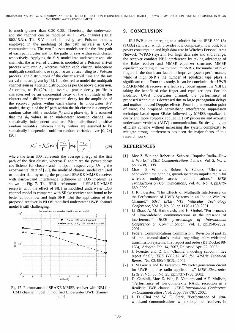
experimental data of [26], the modified channel model can used
to transfer data by using the proposed SRAKE-MMSE receiver
with narrowband interference technique in LOS medium as
shown in Fig.17. The BER performance of SRAKE-MMSE
receiver with the effect of NBI in modified underwater LOS
channel model is compared with SRake receiver and found to be
better at both low and high SNR. But the application of the
proposed receiver in NLOS modified underwater UWB channel
model is still challenging.
Fig.17. Performance of SRAKE-MMSE receiver with NBI for
CM1 channel model in modified Underwater UWB channel
model
9. CONCLUSION
IR-UWB is an emerging as a solution for the IEEE 802.15a
(TG3a) standard, which provides low complexity, low cost, low
power consumption and high data-rate in Wireless Personal Area
Network (WPAN) system. For high data rate and short range,
the receiver combats NBI interference by taking advantage of
the Rake receiver and MMSE equalizer structure. MMSE
equalizer operating at low to medium SNR’s, the number of rake
fingers is the dominant factor to improve system performance,
while at high SNR’s the number of equalizer taps plays a
significant role. From this study, it can be concluded that UWB
SRAKE-MMSE receiver is effectively robust against the NBI by
taking the benefit of rake finger and equalizer taps. For the
modified UWB underwater channel, the performance of
proposed technique is decreased due to large propagation delays
and motion-induced Doppler effects. From implementation point
of view, the proposed narrowband interference suppression
technique based upon SRake followed by MMSE equalizer is
costly and more complex applied in DSP processor and acoustic
underwater vehicles (AUV) communication. So designing an
efficient scheme without increasing the system complexity to
mitigate strong interferences has been the major focus of this
research work.
REFERENCES
[1] Moe Z. Win and Robert A. Scholtz, “Impulse Radio--How
it Works,” IEEE Communications Letters, Vol. 2, No. 2,
pp.36-38, 1998.
[2] Moe Z. Win and Robert A. Scholtz, “Ultra-wide
bandwidth time hopping spread-spectrum impulse radio for
wireless multiple access communications,” IEEE
Transactions on Communications, Vol. 48, No. 4, pp.679-
689, 2000.
[3] J. R. Foerster, “The Effects of Multipath Interference on
the Performance of UWB Systems in an Indoor Wireless
Channel,” 53rd IEEE VTS Vehicular Technology
Conference, Vol. 2, No. 69, pp.1176-1180, 2001.
[4] Li Zhao, A. M. Haimovich, and H. Grebel, “Performance
of ultra-wideband communications in the presence of
interference,” IEEE proceedings of International
Conference on Communication, Vol. 1, pp.2948-2952,
2001.
[5] Federal Communications Commission, Revision of part 15
of the commission’s rules regarding ultra-wideband
transmission systems, first report and order (ET Docket 98-
153), Adopted Feb. 14, 2002, Released Apr. 22, 2002.
[6] J. Foerster and Q. Li, “Channel modeling subcommittee
report final”, IEEE P802.15 WG for WPANs Technical
Report, No. 02/490r0-SG3a, 2002.
[7] JFM Gerrits and JR.Farserotu, “Wavelet generation circuit
for UWB impulse radio applications,” IEEE Electronics
Letters, Vol. 38, No. 25, pp.1737-1738, 2002.
[8] D. Cassioli, Moe Z. Win, F. Vatalaro and A.F. Molisch,
“Performance of low-complexity RAKE reception in a
Realistic UWB channel,” IEEE International Conference
on Communication , Vol. 2, pp. 763-767, 2002.
[9] J. D. Choi and W. E. Stark, "Performance of ultra-
wideband communications with suboptimal receivers in

ISSN: 2229-6948(ONLINE) ICTACT JOURNAL ON COMMUNICATION TECHNOLOGY, MARCH 2012, VOLUME: 03, ISSUE: 01
487
multipath channels," IEEE Journal on Selected Areas in
Communications, Vol. 20, No. 9, pp.1754-1766, 2002.
[10] J. D. Choi and W. E. Stark, “Performance of ultra-
wideband communications with suboptimal receivers in
multipath channels,” IEEE Journal on Selected Areas in
Communications, Vol. 20, No. 9, pp.1754-1766, 2002.
[11] J. Foerster, “The Performance of a Direct-Sequence Spread
Ultra-Wideband System in the Presence of Multipath,
Narrowband Interference and Multiuser Interference,”
IEEE Conference on Ultra Wideband Systems and
Technologies, pp.87-92, 2002.
[12] J.R. Foerster, “Interference modelling of pulse-based UWB
waveforms on narrowband systems,” IEEE 55th Vehicular
Technology Conference, Vol. 4, pp.1931-1935, 2002.
[13] Rajeswaran, V.S. Somayazulu, and J.R. Foerster, “Rake
performance for a pulse based UWB system in a realistic
UWB indoor channel,” IEEE International Conference on
Communications, Vol.4, pp.2879-2883, 2003.
[14] N. Boubaker and K.B. Letaief, “A Low Complexity RAKE
Receiver in a realistic UWB Channel and in the presence of
NBI,” IEEE Wireless Communications and Networking,
Vol. 1, pp.233-237, 2003.
[15] S. Gezici, H. V. Poor and H. Kobayashi, “Optimal and
Suboptimal Finger Selection Algorithms for MMSE Rake
Receivers in Impulse Radio Ultra-Wideband Systems,”
IEEE Wireless Communications and Networking
Conference, Vol. 2, pp.861-866, 2004.
[16] Zhao Guannan, Jin Minglu and Fan Wei, “A Low-
complexity NBI Suppression Algorithm in UWB Systems,
pp.1-4, 2006.
[17] Thomas Zasowski and Armin Wittneben, “UWB
transmitted reference receivers in the presence of co-
channel interference,” IEEE 17th International Symposium
on Personal, Indoor and Mobile Radio Communications,
pp. 1-5, 2006.
[18] M.K Lakshmanan and H. Nikookar, “Mitigation of
interference from wideband IEEE 802.11a source on UWB
wireless communication using frequency selective wavelet
packets,” IEEE International conference on waveform
diversity and design, pp.50–54, 2007.
[19] Huy Quach and Anh Dinh, “Narrowband interference
elimination in UWB communications systems,” Canadian
Conference on Electrical and Computer Engineering, pp.
1341 – 1344, 2007.
[20] Y. Wang and X. Dong, “Spectrum shaping and NBI
suppression in UWB communications,” IEEE Transactions
on Wireless Communications, Vol.6, No.5 pp.1944-1952,
2007.
[21] F. Troesch and A. Wittneben, “MLSE post-detection for
ISI mitigation and synchronization in UWB Low
Complexity Receivers,” IEEE 65th Vehicular Technology
Conference, pp. 2915 – 2919, 2007.
[22] C. Ramesh and V. Vaidehi, “Performance Analysis of
UWB Channels for Wireless Personal Area Network,”
Wireless Personal Communication, Springer, Vol. 41, No.
2, pp. 169-178, 2007.
[23] Xudong Ma, “Reduced Complexity Demodulation and
Equalization Scheme for Differential Impulse Radio UWB
Systems with ISI,” IEEE Sarnoff Symposium, pp.1-5, 2009.
[24] R. Kshetrimayum, “An introduction to UWB communication
systems,” IEEE Potentials, Vol. 28, No. 2, pp.9-13, 2009.
[25] G. Loubet and B. Faure, “Characterization of the
underwater channel for acoustic communications”, Journal
of the Acoustical Society of American, Vol. 105, No. 2,
pp. 1364, 1999.
[26] Xiuzhen Cheng, Haining Shu, Qilian Liang and David
Hung-Chang, “Silent Positioning in Underwater Acoustic
Sensor Networks,” IEEE Transaction on Vehicular
Technology, Vol. 57, No. 3, pp.1756-1766, May 2008.