nanotechnology || nanomaterials and their production
TRANSCRIPT

“09-ch06-101-124-9780080964478” — 2011/6/26 — 10:14 — page 101 — #1
CHAPTER
Nanomaterials and theirProduction 6C H A P T E R C O N T E N T S
6.1 Nanoparticles ... . . . . . . . . . . . . . . . . . . . . . . . . . . . . . . . . . . . . . . . . . . . . . . . . . . . . . . . . . . . . . . . . . . . . . . . 1036.1.1 Comminution and Dispersion . . . . . . . . . . . . . . . . . . . . . . . . . . . . . . . . . . . . . . . . . . 1046.1.2 Nucleation and Growth.. . . . . . . . . . . . . . . . . . . . . . . . . . . . . . . . . . . . . . . . . . . . . . . . 104
6.2 Nanofibers ... . . . . . . . . . . . . . . . . . . . . . . . . . . . . . . . . . . . . . . . . . . . . . . . . . . . . . . . . . . . . . . . . . . . . . . . . . . . 1086.3 Nanoplates and Ultrathin Coatings... . . . . . . . . . . . . . . . . . . . . . . . . . . . . . . . . . . . . . . . . . . . . . . . . . 108
6.3.1 Molecular Beam Epitaxy (MBE) . . . . . . . . . . . . . . . . . . . . . . . . . . . . . . . . . . . . . . . . 1096.3.2 Langmuir Films .. . . . . . . . . . . . . . . . . . . . . . . . . . . . . . . . . . . . . . . . . . . . . . . . . . . . . . . 1096.3.3 Self-Assembled Monolayers (SAMs) . . . . . . . . . . . . . . . . . . . . . . . . . . . . . . . . . . . 113
6.4 Crystallization and Supramolecular Chemistry .. . . . . . . . . . . . . . . . . . . . . . . . . . . . . . . . . . . . . . 1146.5 Composites ... . . . . . . . . . . . . . . . . . . . . . . . . . . . . . . . . . . . . . . . . . . . . . . . . . . . . . . . . . . . . . . . . . . . . . . . . . . 115
6.5.1 Polymer–Nano-Object Blends . . . . . . . . . . . . . . . . . . . . . . . . . . . . . . . . . . . . . . . . . . 1166.5.2 Metal–Matrix Composites . . . . . . . . . . . . . . . . . . . . . . . . . . . . . . . . . . . . . . . . . . . . . . 1196.5.3 Self-Repairing Composites . . . . . . . . . . . . . . . . . . . . . . . . . . . . . . . . . . . . . . . . . . . . . 1206.5.4 Nanofluids for Thermal Transport . . . . . . . . . . . . . . . . . . . . . . . . . . . . . . . . . . . . . . 1216.5.5 Alternating Polyelectrolyte Deposition . . . . . . . . . . . . . . . . . . . . . . . . . . . . . . . . . 122
6.6 Summary... . . . . . . . . . . . . . . . . . . . . . . . . . . . . . . . . . . . . . . . . . . . . . . . . . . . . . . . . . . . . . . . . . . . . . . . . . . . . . 1246.7 Further Reading ... . . . . . . . . . . . . . . . . . . . . . . . . . . . . . . . . . . . . . . . . . . . . . . . . . . . . . . . . . . . . . . . . . . . . . 124
A nanomaterial is a material having one or more external dimensions in the nanoscaleor having internal or surface structure in the nanoscale (Figure 6.1). If the descriptionis to be kept deliberately vague, one could use the word “nanosubstance” merelyto signify that some nanoscale features are involved. Nano-objects are categorizedaccording to the number of their external dimensions in the nanoscale (Figure 6.2).The concept of nano-object includes additional entities not shown in the figure butsometimes referred to, such as nanohorns, whose external dimension in the nanoscaletapers from large to small—that is, a hollow nanocone, except that the principal axismay not be straight. The concept of nanoplate includes all ultrathin coatings, evenif their substrate is not planar, as long as the substrate’s radius of curvature is muchgreater than the thickness of the coating.
A nanostructured material is defined as possessing internal or surface structure inthe nanoscale. This structure may arise due to the presence of contiguous elementswith one or more dimensions in the nanoscale. Primary atomic or molecular (in thechemical sense) structure is excluded (otherwise all materials would necessarily be
Nanotechnology: An Introduction. DOI: 10.1016/B978-0-08-096447-8.00006-5Copyright c© 2011. Published by Elsevier Inc. All rights reserved.
101

“09-ch06-101-124-9780080964478” — 2011/6/26 — 10:14 — page 102 — #2
102 CHAPTER 6 Nanomaterials and their Production
Nanomaterial
Nano-object Nanostructured material
FIGURE 6.1
Fragment of a concept system for nanotechnology (cf. Figure 1.1).
Nano-object (one or moreexternal dimensions in the
nanoscale)
Nanoparticle(3 external dimensions in
the nanoscale)
Nanowire(electrically conducting
nanofiber)
Nanotube(hollow nanofiber)
Nanorod(rigid nanofiber)
Nanofiber(2 external dimensions in
the nanoscale)
Nanoplate(1 external dimension in
the nanoscale)
FIGURE 6.2
Concept system for nano-objects (cf. Figures 1.1 and 6.1). See text for further explanation.
categorizable as nanostructured). Ultimately nanostructured materials should be pro-duced using bottom-to-bottom technology (i.e., mechanosynthesis, see Section 8.3),but currently this is only available for producing minute quantities of matter. Atpresent, the largest exemplar of nanostructured materials is composites comprisingnano-objects embedded in a matrix. In order to distinguish them from materials inwhich the embedded objects are larger than nanoscale, nanostructured compositesmay be called nanocomposites. In such materials, the overall structure is of a statis-tical nature. It would not, however, be appropriate to call such materials “randomlynanostructured”, since almost certainly spacial correlations exist.
Since the above definition refers to “contiguous elements”, it would appear thata heap of nano-objects would also fall into the category of nanostructured material.If the attractive energy of interaction between the objects is insignificant comparedwith thermal energy (i.e., mgd>kBT , where m and d are, respectively, the massand diameter of the object), one may refer to a powder (or an ultrafine powder ora nanopowder if the smallness of the objects needs to be explicitly stated, or indeed“nanoscale granular material”). If the objects attract each other weakly, one may referto an agglomerate; typically the external surface area of an agglomerate is similar tothe sum of the surface areas of the individual objects comprising it. If the objects arestrongly bonded to one another one may refer to an aggregate (typically the external
“09-ch06-101-124-9780080964478” — 2011/6/26 — 10:14 — page 103 — #3
6.1 Nanoparticles 103
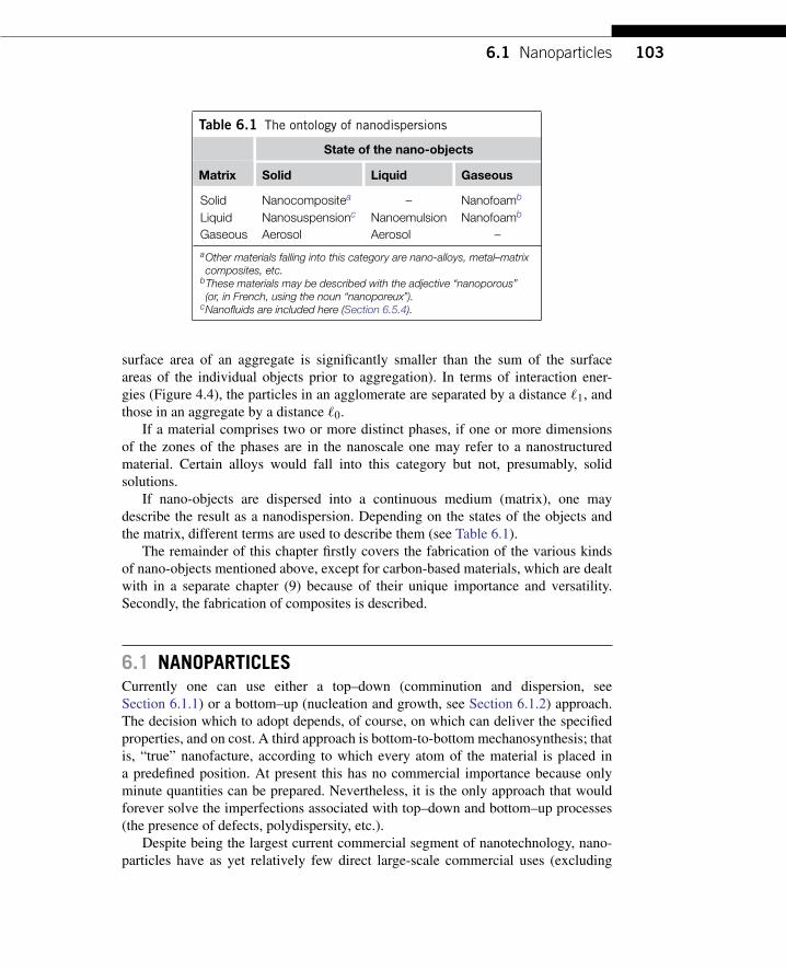
Table 6.1 The ontology of nanodispersions
State of the nano-objects
Matrix Solid Liquid Gaseous
Solid Nanocompositea – Nanofoamb
Liquid Nanosuspensionc Nanoemulsion Nanofoamb
Gaseous Aerosol Aerosol –
aOther materials falling into this category are nano-alloys, metal–matrixcomposites, etc.
bThese materials may be described with the adjective “nanoporous”(or, in French, using the noun “nanoporeux”).
cNanofluids are included here (Section 6.5.4).
surface area of an aggregate is significantly smaller than the sum of the surfaceareas of the individual objects prior to aggregation). In terms of interaction ener-gies (Figure 4.4), the particles in an agglomerate are separated by a distance `1, andthose in an aggregate by a distance `0.
If a material comprises two or more distinct phases, if one or more dimensionsof the zones of the phases are in the nanoscale one may refer to a nanostructuredmaterial. Certain alloys would fall into this category but not, presumably, solidsolutions.
If nano-objects are dispersed into a continuous medium (matrix), one maydescribe the result as a nanodispersion. Depending on the states of the objects andthe matrix, different terms are used to describe them (see Table 6.1).
The remainder of this chapter firstly covers the fabrication of the various kindsof nano-objects mentioned above, except for carbon-based materials, which are dealtwith in a separate chapter (9) because of their unique importance and versatility.Secondly, the fabrication of composites is described.
6.1 NANOPARTICLESCurrently one can use either a top–down (comminution and dispersion, seeSection 6.1.1) or a bottom–up (nucleation and growth, see Section 6.1.2) approach.The decision which to adopt depends, of course, on which can deliver the specifiedproperties, and on cost. A third approach is bottom-to-bottom mechanosynthesis; thatis, “true” nanofacture, according to which every atom of the material is placed ina predefined position. At present this has no commercial importance because onlyminute quantities can be prepared. Nevertheless, it is the only approach that wouldforever solve the imperfections associated with top–down and bottom–up processes(the presence of defects, polydispersity, etc.).
Despite being the largest current commercial segment of nanotechnology, nano-particles have as yet relatively few direct large-scale commercial uses (excluding

“09-ch06-101-124-9780080964478” — 2011/6/26 — 10:14 — page 104 — #4
104 CHAPTER 6 Nanomaterials and their Production
photographic emulsions and carbon black, both of which long precede the nano-era);mostly their applications are in composites (i.e., a mixture of component A addedto a matrix of component B, the latter usually being the majority component)—ananocomposite differs from a conventional composite only insofar as the additive isnanosized and better dispersed in the matrix. Applications such as reagents for theremediation of contaminated soils (e.g., iron nanoparticles for decomposing chlor-inated hydrocarbons) are being investigated, although the present very imperfectknowledge about the effects of such nanoparticles on soil ecosystems is preventingrapid exploitation in this area.
6.1.1 Comminution and DispersionThis top–down approach involves taking bulk material and fragmenting it. Crushingand grinding have typically been treated as low-technology operations; theoreticalscientists seeking to formalize the process beginning with the formulation of mech-anistic phenomenological rules (e.g., the random sequential fragmentation formalism)have hitherto had little industrial impact. The main advantages are universality (i.e.,applicability to virtually any material) and low cost. Even soft organic matter (e.g.,leaves of grass) can be ground by first freezing it in liquid nitrogen to make it brittle.
The main disadvantages are polydispersity of the final particles, the introduc-tion of many defects (including contamination by the material used to make thegrinding machinery—the smaller the particles the worse the contamination becauseit is introduced at the surface of the particles) and the impossibility of achievingnanoscale comminution, depending on the material: as a compressed brittle body ismade smaller, its fracture strength increases until at a certain critical size crack prop-agation becomes impossible [90], cf. Section 2.7. This explains the well-known sizelimit to the crushing of materials—typically above the nanoscale (e.g., around 0.8µmfor calcium carbonate).
Crushing and grinding are venerable industrial processes in the form of ham-mering, rolling or ball-milling, but the advent of nanotechnology has given rise tonovel, very well-controlled methods of achieving monodisperse nanoparticle gener-ation by comminution and dispersion. One such process is electroerosion dispersion(EED) [120], in which granulated metal is ground into a fine powder by electri-cal discharges—typically a few hundred volts are discharged in a microsecond. Theplasma temperature in the discharge filament is 10 000 to 15 000 K, sufficient to meltany metal.
6.1.2 Nucleation and GrowthThis process involves a first order phase transition from an atomically dispersed phaseto a solid condensed phase. During the first stage of the transition fluctuations in thehomogeneous, metastable parent phase result in the appearance of small quantitiesof the new phase. The unfavorable process of creating an interface opposes the gainin energy through the reduction in supersaturation of the parent phase, leading to a

“09-ch06-101-124-9780080964478” — 2011/6/26 — 10:14 — page 105 — #5
6.1 Nanoparticles 105
Nucleationrate
0
ΔG
n* n
FIGURE 6.3
Sketch of the variation of free energy of a cluster containing n atoms (cf. Figure 2.2). Themaximum corresponds to the critical nucleus size. Clusters that have managed throughfluctuations to climb up the free energy slope to reach the critical nucleus size have anequal probability to shrink back and vanish, or to grow up to microscopic size.
critical size of nucleus, n∗, above which the nucleic develop rapidly and irreversiblyinto the new “bulk” (albeit nanoscale) phase. Many syntheses were reported in the19th century (e.g., [50, 63]).
When atoms cluster together to form the new phase, they begin to create aninterface between themselves and their surrounding medium, which costs energy.Denoting the interfacial tension by γ , and using subscripts 1 and 2 to denote thenew phase and surrounding medium, respectively (see Section 3.2), the energy costis Aγ 12, where A is the area of the cluster’s surface, equal to (4π)1/3(3nv)2/3, wheren is the number of atoms in the cluster, and v the volume of one atom. At the sametime each atom contributes to the cohesive energy of the new phase. Summing thesetwo contributions, at first the energy will increase with increasing n, but ultimatelythe (negative) cohesive energy of the bulk will win (Figure 6.3).
In order to synthesize nanoparticles via nucleation and growth, firstly the atomsare dispersed (dissolved) in a medium under conditions such that the dispersion is sta-ble. Then, one or more of the external parameters is changed such that the bulk phaseof the material now dispersed is stable. This could be accomplished, for example,by cooling the vapor of the material. The formation of the new bulk phase is a firstorder phase transition involving nucleation. Chance fluctuations will generate criticalnuclei (see Figure 6.3).
Compound particles can be synthesized by chemical reaction [135]. Suppose theformula of the desired substance is MX, where M represents a metal such as silveror cadmium, and X a metalloid such as sulfur or selenium. One then prepares twosolutions of soluble compounds of M and X (for example, silver nitrate and sodiumsulfide), which are then mixed together. Figures 6.4 and 6.5 show some examples.
Two key challenges in this process are: (i) to obtain particles that are as uniform(monodisperse) as possible; and (ii) to be able to control the mean size. In the case of

“09-ch06-101-124-9780080964478” — 2011/6/26 — 10:14 — page 106 — #6
106 CHAPTER 6 Nanomaterials and their Production
10nm
FIGURE 6.4
Transmission electron micrograph of cadmium sulfide nanoparticles prepared in theauthor’s laboratory by nucleation and growth in aqueous solution [135]. The apparentagglomeration is an artifact of the sample preparation, in which a drop of the particlesuspension was placed on a carbon-coated copper grid and the water allowed toevaporate. This final stage of the evaporation process can be observed in situ in theelectron ultramicroscope: the water forms a receding thin film and capillary forces(Section 3.3) at its edge drag the particles together.
synthesis by chemical reaction, the key parameter is the rate of mixing. Two extremesituations yield the desired monodispersity: ultrarapid mixing of very concentratedsolutions, and ultraslow mixing of very dilute solutions. In the former case, a verylarge number of critical nuclei are formed almost simultaneously (the rate of creationof critical nuclei is proportional to the supersaturation; that is, the ratio of the actualconcentration to the solubility product of MX); growth of material onto the initiallyformed nuclei is too slow to compete with fresh nucleation in sinking the added mass.Conditions should be chosen such that the nuclei are just able to grow sufficientlylarge to be effectively irreversibly stable before all the free M and X ions have beenscavenged by the formation of nuclei. Further growth to any desired size can thenbe achieved in a separate, subsequent, stage by adding fresh material at a rate justsufficient to allow all the nuclei to grow without creating any new ones.
In the latter case, nuclei are formed extremely rarely and are unable to growbeyond the size of minimum stability because of the lack of material; diffusion offresh material to the few nuclei formed initially is too slow to prevent new nuclei

“09-ch06-101-124-9780080964478” — 2011/6/26 — 10:14 — page 107 — #7
6.1 Nanoparticles 107
100nm
FIGURE 6.5
Transmission electron micrograph of hematite nanoparticles prepared in the author’slaboratory by nucleation and growth in aqueous solution (cf. Figure 6.4).
been formed in order to sink the added reagents. Once a sufficient number of nucleihas been synthesized, they can be grown up to the desired size as in the previous case.This approach is very effective for synthesizing monodisperse noble metal particles(e.g., gold) by very slowly reducing the solution of a salt of the metal [50].
Because of the Kelvin relation (equation 2.7), larger particles will have a slightlylower solubility than smaller ones. Therefore, there will be a slight tendency for thesmaller ones to dissolve, and for their material to be deposited onto the bigger ones.This process is known as Ostwald ripening and under certain conditions may permitthe size distribution of a collection of particles to be narrowed, albeit at the price ofincreasing the mean size.
Once a collection of nuclei has been synthesized, it is very easy to grow shellsof different materials around them; one simply needs to ensure that the new materialis added at a sufficient rate to allow all the particles to grow uniformly, and not sorapidly that fresh nuclei are formed.
The interfacial free energy for aggregation of particles made from material 1 inthe presence of medium 2 is given by (see Section 3.2.1):
1G121 =1G11+1G22− 21G12 (6.1)
“09-ch06-101-124-9780080964478” — 2011/6/26 — 10:14 — page 108 — #8
108 CHAPTER 6 Nanomaterials and their Production
where 1G11 and 1G22 are the cohesive energies of materials 1 and 2, and 1G12is the solvation energy. Note that water has a very large cohesive energy. There-fore, particles of almost any insoluble material synthesized in water are likely toaggregate, unless appropriate measures to ensure their hydration are taken. A usefulstrategy is to synthesize the particles in the presence of a very hydrophilic mater-ial such as polyethylene glycol or a polyion such as hexametaphosphate, which isable to adsorb on the surface of the particles and effectively hydrate them. MichaelFaraday’s famous synthesis of gold nanoparticles used citrate ions to hydrate theirsurface [50]. Crystals of silver chloride, silver bromide and silver iodide ranging insize from tens of nanometers to micrometers, which form the basis of conventionalsilver halide-based photography, are stabilized in the emulsions used to coat glass orpolymer substrates by the natural biopolymer gelatin.
Micelles and superspheres are dealt with in Section 8.2.9.
6.2 NANOFIBERS“Nanofiber” is the generic term describing nano-objects with two external dimensionsin the nanoscale. A nanorod is a rigid nanofiber, a nanotube is a hollow nanofiber, anda nanowire is an electrically conducting nanofiber (Figure 6.2).
Two approaches are presently mainly used to synthesize nanofibers. For somesubstances, under certain conditions, the natural growth habit is acicular. Therefore,the methods described in Section 6.1.2 can be used to generate nuclei, followedby a growth stage to elongate them. Heterogeneous nucleation can be induced atthe solid/gas interface by predepositing small catalytic clusters. Upon addition ofvapor, condensation on the clusters and growth perpendicular to the solid substratetakes place. This is used as an efficient way of synthesizing carbon nanotubes (seeSection 9.2). If uniform nanopores can be formed in a membrane (e.g., by laserdrilling or by self-assembly) they can be used as templates for nanofiber formation.The material for the fiber should be deposited as a shell on the inner surface of thepores (if the goal is to make nanotubes), or else should completely fill the pores (fornanorods). Nanofibers, especially nanorods, formed by either of the two previousmethods can also be used as templates for making nanotubes of a different material.Lieber has reported the general synthesis of semiconductor nanowires with controlof diameter [44, 66].
6.3 NANOPLATES AND ULTRATHIN COATINGSMany of the traditional engineering methods of fabricating thin coatings on a sub-strate have not produced objects in the nanoscale because typically they have beenmore than 100 nm thick. Nevertheless, the trend is to develop thinner functional sur-faces by coating or otherwise modifying bulk material, and insofar as the coating or

“09-ch06-101-124-9780080964478” — 2011/6/26 — 10:14 — page 109 — #9
6.3 Nanoplates and Ultrathin Coatings 109
modification is engineered with atomic precision, it belongs to nanotechnology, andif it is nanostructured either laterally or perpendicular to the substrate, it will rank asa nanomaterial even if its overall thickness exceeds 100 nm.
The surface treatment of bulk material, especially metals, is an ancient technol-ogy. In the cases where nanoscale structural features were apparently necessary toensure having the required attributes (e.g., in Damascus swords [146]), althoughthe structures were created deliberately the nanoscale aspect might be consideredas essentially inadvertent since the technologist is unlikely to have explicitly envi-sioned the nanoscale structuring. This is in contrast to, for example, the medicinaluse of nanoparticulate gold (introduced by Paracelsus in the 16th century), when itwas realized that a metal could only be assimilated by a living human organism if itwas sufficiently finely divided.
Completely in the spirit of nanotechnology are the monomolecular layers, nowcalled Langmuir films, transferred to solid substrata using the Langmuir–Blodgett andLangmuir–Schaefer techniques; these films might only be a few nanometers thick.Their preparation is a “top–down” approach.
Many physical vapor deposition techniques (such as an evaporation and mag-netron sputtering) create films thicker than the nanoscale and hence are out of thescope of this book. Molecular beam epitaxy (MBE), a technique of great importancein the semiconductor processing industry, is briefly covered in Section 6.3.1 (see alsoSection 8.1.1).
6.3.1 Molecular Beam Epitaxy (MBE)MBE can be considered as a precise form of physical vapor deposition (PVD). Solidsource materials are placed in evaporation cells around a centrally placed, heated,substrate. Pressures less than 10−5 torr ensure that the mean free path of the vaporexceeds practical vacuum chamber dimensions (∼ 1 m), the molecular beam con-dition. Ultrahigh vacuum (UHV) conditions are needed to ensure the absence ofcontamination from residual gases (from the chamber walls, etc.). A few secondsare typically required to grow one monolayer. The technique has been developedvery successfully using a practical, empirical approach—thermodynamic analysis isdifficult because the various parts of the system (sources, substrate, chamber wall)are at different temperatures.
6.3.2 Langmuir FilmsLangmuir films, first reported by Pockels at the end of the 19th century, consist of amonomolecular layer of amphiphiles (molecules consisting of an apolar nanoblockconjoined to a polar block of roughly the same size) floating on water. The polar“heads” dip into the water and the apolar “tails” stick up into the air. In other words,the film precursors are molecules of general formula XP, where X is (typically) anapolar chain (e.g., an alkyl chain), called the “tail”, and P is a polar “head” group suchas oligoethylene oxide, or phosphatidylcholine. When spread on water they mostly
“09-ch06-101-124-9780080964478” — 2011/6/26 — 10:14 — page 110 — #10
110 CHAPTER 6 Nanomaterials and their Production
(a) (b) (c)
(d)
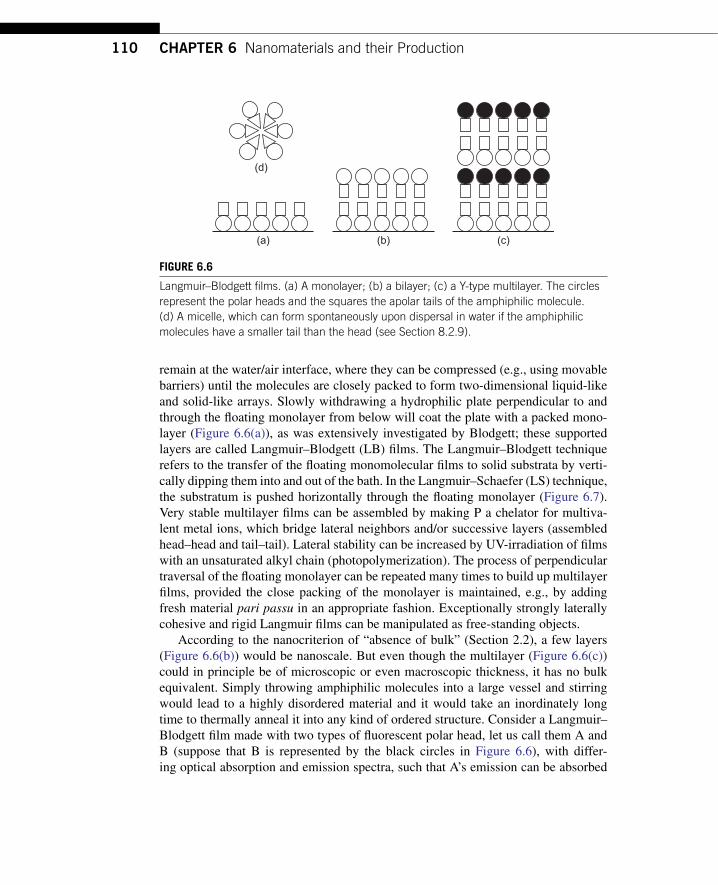
FIGURE 6.6
Langmuir–Blodgett films. (a) A monolayer; (b) a bilayer; (c) a Y-type multilayer. The circlesrepresent the polar heads and the squares the apolar tails of the amphiphilic molecule.(d) A micelle, which can form spontaneously upon dispersal in water if the amphiphilicmolecules have a smaller tail than the head (see Section 8.2.9).
remain at the water/air interface, where they can be compressed (e.g., using movablebarriers) until the molecules are closely packed to form two-dimensional liquid-likeand solid-like arrays. Slowly withdrawing a hydrophilic plate perpendicular to andthrough the floating monolayer from below will coat the plate with a packed mono-layer (Figure 6.6(a)), as was extensively investigated by Blodgett; these supportedlayers are called Langmuir–Blodgett (LB) films. The Langmuir–Blodgett techniquerefers to the transfer of the floating monomolecular films to solid substrata by verti-cally dipping them into and out of the bath. In the Langmuir–Schaefer (LS) technique,the substratum is pushed horizontally through the floating monolayer (Figure 6.7).Very stable multilayer films can be assembled by making P a chelator for multiva-lent metal ions, which bridge lateral neighbors and/or successive layers (assembledhead–head and tail–tail). Lateral stability can be increased by UV-irradiation of filmswith an unsaturated alkyl chain (photopolymerization). The process of perpendiculartraversal of the floating monolayer can be repeated many times to build up multilayerfilms, provided the close packing of the monolayer is maintained, e.g., by addingfresh material pari passu in an appropriate fashion. Exceptionally strongly laterallycohesive and rigid Langmuir films can be manipulated as free-standing objects.
According to the nanocriterion of “absence of bulk” (Section 2.2), a few layers(Figure 6.6(b)) would be nanoscale. But even though the multilayer (Figure 6.6(c))could in principle be of microscopic or even macroscopic thickness, it has no bulkequivalent. Simply throwing amphiphilic molecules into a large vessel and stirringwould lead to a highly disordered material and it would take an inordinately longtime to thermally anneal it into any kind of ordered structure. Consider a Langmuir–Blodgett film made with two types of fluorescent polar head, let us call them A andB (suppose that B is represented by the black circles in Figure 6.6), with differ-ing optical absorption and emission spectra, such that A’s emission can be absorbed

“09-ch06-101-124-9780080964478” — 2011/6/26 — 10:14 — page 111 — #11
6.3 Nanoplates and Ultrathin Coatings 111
(a)
(b)
W
B
Subphase
R
BW
Subphase
FIGURE 6.7
The Langmuir–Schaefer (LS) technique. (a) The polar substrate is slowly drawn upwardsthrough the Langmuir film to deposit a monolayer. (b) The coated substrate, now apolar, ispushed horizontally through the Langmuir film to deposit a second monolayer (and iscaught by the receptacle R). This operation is equivalent to a very rapid vertical descent.The rapidity is needed to ensure that the mensicus curves downwards during deposition.
by B (the process is called Forster energy transfer), which in turn would emit lightat wavelength λB. Then, exciting A (with light of wavelength λA) would result inemission of wavelength λB. On the other hand, if A and B were simply mixed atrandom, irradiating the mixture with λA would mostly result in emission of wave-length λA, since A and B have to be very close to each other in order for Forsterenergy transfer to occur: nanoscale structure results in qualitatively different behav-ior. Amphiphilic molecules can also form a bicontinuous cubic phase, which ispervasively nanostructured, although it can be of indefinite (i.e., macroscopic) extent.
If two different immiscible amphiphiles are mixed on the Langmuir trough, theresulting variegated structures can be imaged using scanning probe microscopy after

“09-ch06-101-124-9780080964478” — 2011/6/26 — 10:14 — page 112 — #12
112 CHAPTER 6 Nanomaterials and their Production
20 nm
0nm20 µm × 20 µm
FIGURE 6.8
Scanning force micrograph (contact mode) of a mixed behenic acid/pentadecanoic acidfilm transferred horizontally onto muscovite mica at a surface pressure of 15 mN/m. Imagesize: 20× 20 µm (reproduced with permission from [3]).
transferring the Langmuir film to a solid support using the Langmuir–Schaefer tech-nique (Figure 6.8). These experiments have shown (a) how difficult it is to findconvenient mixtures, and (b) how difficult it is to predict theoretically what pat-terns result. There are moreover experimental difficulties in imaging texture (seeChapter 5) at scales below a few tens of nanometers. The lack of metrology tech-niques suited for this purpose is in fact one of the main current hindrances to progressin the field.
Although there has been recurrent industrial interest in Langmuir–Blodgett (LB)films for numerous applications in microelectronics and integrated optics, the cum-bersome nature of the fabrication methodology, well suited to laboratory research butdifficult to automate, and the difficulty of creating defect-free films, have militatedagainst its adoption. The problem of defects (e.g., pinholes in the insulating layerof a field-effect transistor (FET), Figure 7.6) can, however, be overcome by redu-cing the component area (Section 10.4), suggesting that nanoscale electronics mightsee a revival of interest. One attractive feature is the versatile chemistry allowingenvironmentally responsive films to be synthesized; bio-inspired films in a chem-FET configuration can be responsive to both total captured particle number and theirstate of aggregation (see, e.g., [138]). Bio-inspired LB films are typically in the

“09-ch06-101-124-9780080964478” — 2011/6/26 — 10:14 — page 113 — #13
6.3 Nanoplates and Ultrathin Coatings 113
liquid crystalline phase, in which defects are self-annealed. Moreover, for electronicsapplications only very thin films are needed, whereas an optical waveguide requires∼ 100 monolayers, the defect-free assembly of which is cumbersome.
Post-processing LB films expands the fabrication possibilities. Blodgett herselfexplored “skeleton” films prepared by selectively dissolving away one component ofa mixed film. Any multivalent metal or metal compound nanoplate can be preparedfrom a metal–fatty acid LB film (e.g., dysprosium behenate) which is then pyrolysedto remove the organic moiety.
Under certain conditions, regular striated patterns can be formed during LBdeposition [156]. The cause is dynamic instability of substrate wetting.
6.3.3 Self-Assembled Monolayers (SAMs)If particles randomly and sequentially added to the solid/liquid interface are asym-metrical, i.e. elongated, and having affinity for the solid substratum at only one end(but the ability to move laterally at the interface), and with the “tail” (the rest) poorlysolvated by the liquid, they will tend to adsorb in a compact fashion, by strong lat-eral interaction between the tails (Figure 6.9). This is a practical procedure of someimportance for modifying the surfaces of objects fabricated by other means. The pre-cursors are molecules of general formula XR, where X is (typically) an apolar chain(e.g. alkyl), and R is a ligand capable of binding to a substratum. Addition of XR tothe metal surface results in a closely packed array of XR. The film is stabilized byhydrogen or chemical bonds to the substrate, and lateral LW forces between the X.
L L
X X
R R
S
FIGURE 6.9
A (fragment of a) self-assembled monolayer. The component molecules have the generalformula LXR, where X is an apolar chain (e.g., alkyl), and R is a reactive group capable ofbinding to the substratum S. X can be functionalized at the end opposite from R with agroup L to form molecules L–XR; the nature of L can profoundly change the wettingproperties of the SAM.

“09-ch06-101-124-9780080964478” — 2011/6/26 — 10:14 — page 114 — #14
114 CHAPTER 6 Nanomaterials and their Production
Self-assembled monolayers were discovered by Bigelow et al. [18]. Currentlythe two main types of R are –SH (thiol or mercaptan), which binds strongly to Au,Ag, Pt, Cu, Hg, etc.), and organosilanes, which bind strongly (bond covalently) tosilica. These chemical requirements are the main constraints limiting the versatilityof the technology. The original example was eicosyl alcohol (C20H41OH) dissolvedin hexadecane (C16H34) adsorbing on silica glass. Later, molecules with R = –SHand the organosilanes were investigated. If the tail moiety X is poorly solvated bythe liquid, its flexibility may enable it to be compactified while the molecule is inthe bulk solution, tending to prevent self-aggregation, and only unfurling itself afterR is attached to the solid surface—a rudimentary form of programming (cf. pro-grammable self-assembly, Section 8.2.8). SAMs provide a very convenient way tochange the wettability of a solid surface. Bigelow et al.’s monolayers were bothhydrophobic and oleophobic. An octadecanethiol (R = –SH) film adsorbed on goldwould be both oil and water repellent; if L = –OH it will be hydrophilic (seeSection 3.2.1).
X can be functionalized at the end opposite from R with reactive groups to formmolecules RXL. These can profoundly change the wetting properties of the assem-bled monolayer. For example, whereas octadecanethiol (L = –H) films are both oiland water repellent, if L = –OH then oil and water will spread. If they are bulky,the functionalized molecules should be mixed with unfunctionalized ones to avoidpacking defects. Mixtures with different chain lengths (e.g., X = C12 and C22) giveliquid-like SAMs. The biologically ubiquitous lipid bilayer membrane could be con-sidered to belong to this category. The component molecules are of type XR, where Xis an alkyl chain as before, and R is a rather polar “head group”, the volume of whichis typically roughly equal to that of X. Placing XR molecules in water and gently agi-tating the mixture will spontaneously lead to the formation of spherical bilayer shellsRXXR called vesicles. The vesicles will coat a planar hydrophilic substratum with alipid bilayer when brought into contact with it [38].
SAMs can be patterned using photolithography, or “stamping” (microletterpress),to create patterns on substrata (e.g., gold and/or silica) to which the SAM precursormolecules will bind, leaving other zones free. In this procedure, the required patternis the first created in relief on a silicon substrate, which is then used as a mould for theelastomeric polymer PDMS (polydimethylsiloxane). The SAM molecules can be useddirectly as ink to coat the projecting parts of the relief pattern, which is then stampedonto the substratum, or else the ink is some substance that passivates the substratumwith respect to the SAM molecules, which then selectively bind as required.
6.4 CRYSTALLIZATION AND SUPRAMOLECULARCHEMISTRY
It is a remarkable fact that many or even most organic molecules, despite their usu-ally very complicated shapes, are able to spontaneously form close-packed crystals.
“09-ch06-101-124-9780080964478” — 2011/6/26 — 10:14 — page 115 — #15
6.5 Composites 115
Perhaps only familiarity with the process prevents it from occupying a more prom-inent place in the world of self-assembly. In seeking to understand this remarkablephenomenon better, Kitaigorodskii formulated an Aufbau principle [92], accordingto which the self-assembly (cf. Section 8.2.1) of complicated structures takes placein a hierarchical fashion in the following sequence:
Stage 0 a single molecule (or a finite number of independent molecules).Stage 1 single molecules join up to form linear chains.Stage 2 the linear chains are bundled to form two-dimensional monolayers.Stage 3 the two-dimensional monolayers are stacked to form the final three-
dimensional crystal.
Many natural structures are evidently hierarchically assembled. Wood, for example,derives its structural strength from glucose polymerized to form cellulose chains,which are bundled to form fibrils, which are in turn glued together using lignin toform robust fibers. Note that the interactions between the molecular components ofthe crystal may be significantly weaker than the covalent chemical bonds holdingthe atomic constituents of the molecules together. Such weakness enables defects tobe annealed by locally melting the partially formed structure. There is an obviousanalogy between “crystallization” in two dimensions and tiling a plane. Since tilingis connected to computation, self-assembly, which can perhaps be regarded as a kindof generalized crystallization, has in turn been linked to computation.
Just as quantum dots containing several hundred atoms can in some sense (e.g.,with regard to their discrete energy levels) be regarded as “superatoms” (Section 2.5),so can supramolecular assemblies (typically made up from very large and elabo-rate molecules) be considered as “supermolecules”. The obtainable hierarchicallyassembled structures—an enormous literature has accumulated—provide powerfuldemonstrations of the Kitaigorodskii Aufbau principle. The use of metal ions asorganizing centers in these assemblies has been a particularly significant practicaldevelopment.
6.5 COMPOSITESMost of the materials around us are composites. Natural materials such as wood arehighly structured and built upon sophisticated principles. The basic structural unit iscellulose, which is a polymer of the sugar glucose, but cellulose on its own makes afloppy fabric (think of cotton or rayon), hence to give it strength and rigidity it mustbe glued together into a rigid matrix. This is accomplished by the complex multi-ring aromatic molecule lignin. Another example is the shell of marine molluscs suchas the abalone. They are composed of about 95% by volume of thin platelets, smallenough to rank as nano-objects, of aragonite, a form of calcium carbonate and about5% of protein. The toughness of the composite seashell exceeds by more than tenfoldthe toughness of pure calcium carbonate.
“09-ch06-101-124-9780080964478” — 2011/6/26 — 10:14 — page 116 — #16
116 CHAPTER 6 Nanomaterials and their Production
A striking thing about these natural composites is the enormous increase in desir-able properties, such as stiffness or toughness, through small (by volume or mass)inclusions of another material that would, by its nature, normally rank as the matrixin artificial composites. In contrast, the matrix in artificial composites is usually themajority component (in mass or volume or both). The principle of combining two ormore pure substances with distinctly different properties (which might be mechani-cal, electrical, magnetic, optical, thermal, chemical, and so forth) in order to create acomposite material that combines the desirable properties of each to create a multi-functional substance has been refined by humans over millennia, presumably mostlyby trial and error. Typically, the results are, at least to a first approximation, merelyadditive. Thus we might write a sum of materials and their properties like
cellulose high tensile strength self-repellent
+ lignin weak sticky= wood strong cohesive
Empirical knowledge is used to choose useful combinations, in which the desir-able properties dominate—in principle one might have ended up with a weak andrepellent material. The vast and always growing accumulation of empirical knowl-edge usually allows appropriate combinations to be chosen. Indeed, the motif ofstrong fibers embedded in a sticky matrix is very widely exploited, other examplesbeing glass fiber- and carbon fiber-reinforced polymers.
There are two principal motivations for creating composites. The first is toincrease the toughness of the majority component (as in the seashell). This occurs bydividing up the monolithic material into nano-objects and gluing the objects together.The increase in toughness comes partly through the increased ductility of the com-minuted objects (Sections 2.7 and 6.1.1) and partly through the fact that any fracturethat does occur can only extend to the object boundary or, if it occurs in the matrix,to the nearest object lying in its path, a distance which might well be shorter than theobject size. Particularly in this kind of composite the wetting of the principal phaseby the glue is of extreme importance. Empirical knowledge is now backed up andextended by fundamental knowledge of the molecular-scale forces involved, but nat-ural materials still far surpass artificial ones in this respect. Proteins in particular arevery versatile glues because of the variety of chemical functionalities possessed byamino acids. The second motivation is the combination of properties—these com-posites might well be called composites to distinguish them from the other kind; forexample ultrahard nanoparticles might be added to a relatively soft polymer matrixto create a hard, plastic material.
6.5.1 Polymer–Nano-Object BlendsIn fact, most of the recognized successes in nanomaterials so far have been not inthe creation of totally new materials through mechanosynthesis (see Section 8.3),which is still an unrealized goal, but in the more prosaic world of blending, which

“09-ch06-101-124-9780080964478” — 2011/6/26 — 10:14 — page 117 — #17
6.5 Composites 117
is the simplest form of combination. For example, one adds hard particles to a softpolymer matrix to create a hard, abrasion-resistant coating. As with atomically-basedmechanosynthesis, the results are, to a first approximation, additive. Thus we mightagain write a sum like
polypropylene flexible transparent
+ titanium dioxide rigid opaque= thin film coating (paint) flexible opaque
This is not actually very new. Paint, a blend of pigment particles in a matrix(the binder), has been manufactured for millennia. What is new is the detailed atten-tion paid to the nanoparticulate additive. Its properties can now be carefully tailoredfor the desired application. If one of components is a recognized nanosubstance—a nanoparticle or nanofiber, for example—it is acceptable to describe the blend as ananostructured material. Other applications of this kind include ultralow permeabilitymaterials for food packaging, for which it is often undesirable to restrict the ingressof oxygen. The main principle here is to blend particles of a very high aspect ratio(fragments of nanoplates rather than nanoparticles) into the polymer such that theprincipal plane of the objects is perpendicular to the route of ingress. The tortuosityof gas diffusion is vastly increased in such materials. Very often it is sufficient toapply an ultrathin coating onto a conventional flexible polymer substrate to achievethe desired diminution of gas permeability. The design of friction damping com-posites requires careful consideration of the viscoelastic properties of the material.“Self-cleaning” and anti-grafitti coatings rely on the active, typically photo-induced,chemistry taking place at the surface of the nanoparticles included in the matrix.The Paradigm of Paint. The biggest range of applications for such nanocompositesis in thin film coatings—in other words paint. This is a much older composite thanmost other nanomaterials. Paint consists of a pigment (quite possibly made of nano-particles) dispersed in a matrix of varnish. Paint can be said to combine the opacityof the pigment with the film-forming capability of the varnish.
Traditional pigments may comprise granules in the micrometer size range; grind-ing them a little bit more finely (if possible—see Section 6.1.1) turns them intonano-objects. Compared with transparent varnish, paint combines the attribute of pro-tection from the environment with the attribute of color. The principle can obviouslybe (and has been) extended practically ad libitum: by adding very hard particles toconfer abrasion resistance; metallic particles to confer electrical conductivity; tabularparticles to confer low gas permeability, and so on.
The purpose of adding materials to a polymer matrix is, then, to enhance prop-erties such as stiffness, heat resistance, fire resistance, electrical conductivity, gaspermeability, and so forth; the object of any composite is to achieve an advantageouscombination of properties. If the matrix is a metal, then we have a metal–matrix com-posite (MMC, Section 6.5.2). A landmark was Toyota’s demonstration in 1991 thatthe incorporation of a few weight percent of a nanosized clay into a polyamide matrixgreatly improved the thermal, mechanical (e.g., doubled the tensile modulus) and gas
“09-ch06-101-124-9780080964478” — 2011/6/26 — 10:14 — page 118 — #18
118 CHAPTER 6 Nanomaterials and their Production
permeability (barrier) properties of the polymer compared with the pure polymer orthe conventional composite made with micrometer-sized additive. This was the firstcommercial nanocomposite.
Another mineral–polymer composite is the material from which many naturalseashells are constructed: platelets of aragonite dispersed in a protein matrix (seealso Section 6.5.5). In this case, however, the “matrix” only constitutes a few percentof the volume of the composite.
There is no general theory suggesting that the advantage scales inversely withadditive size; whether a nanocomposite is commercially viable depends on all theparameters involved. There is such a huge variety of materials that it is perhaps futileto attempt a generalization. However, the very small size of individual nanoparticleswould make it feasible to incorporate a greater variety of materials within the matrixfor a given additive weight percent. Very often, ensuring wetting of the particle bythe matrix presents a significant technological hurdle. Most successful compositesrequire the additive to be completely wetted by the matrix. Wetting behavior can bepredicted using the Young–Dupre approach (see Section 3.2); if, however, the particlebecomes very small, the surface tension will exhibit a curvature-dependent deviationfrom the bulk value appropriate for a planar interface.
The three main fabrication routes for polymeric nanocomposites are:
1. Blending preformed nanoparticles with the matrix, which is typically in themolten state.
2. Dispersing preformed nanoparticles in monomer and polymerizing the matrixaround the nanoparticles (the Toyota composite mentioned above followed thisroute: modified clay was swollen in the presence of caprolactam followed bypolymerization).
3. Synthesizing the nanoparticles in situ within the matrix.
In each case the goal is to disperse the composites uniformly in the matrix. Hence thechemistry of the particle–composite interface is very important.
Nanocomposites can in principle be substituted for pure polymer in most appli-cations. Nevertheless, there is persistent reluctance to use them in structurally vitalcomponents since extensive data on their long-time performance is still lacking.A general difficulty is that the improved strength, stiffness, etc. of the compositesinevitably results in their being subjected to increased designed stress—otherwisethere would be no advantage in using them—and hence diminished tolerance todamage.Polymers with Added Electro-Active Materials. This is a typical functionality-enhancing technology. Antimony tin oxide (ATO) has become a popular additivefor applications such as protection against electromagnetic interference (EMI) andelectrostatic discharge (ESD). Antistatic coatings incorporate additives with bothhydrophobic and hydrophilic radicals, ideally concentrated in the interfacial zonebetween the polymer and the air: the hydrophobic radicals are oriented towards thepolymer and the hydrophilic radicals towards the air, whence they attract moisture,whose conductivity allows static charge accumulation to be dissipated.

“09-ch06-101-124-9780080964478” — 2011/6/26 — 10:14 — page 119 — #19
6.5 Composites 119
Polymers made conductive by the addition of electroactive materials are of grow-ing importance in the automotive industry. If used for body panels, for example,electrostatic spray painting is enabled, thereby reducing the need for primers, andwhich in turn improves painting reliability, reduces costs and lessens the impact onthe environment by using less volatile organic solvents. Conductive plastics havealso been used to make fuel pipes for automobiles, eliminating the build-up of staticelectricity and the danger of inadvertent ignition from a spark.
Much effort is currently being devoted to creating photovoltaic solar cells fromsemiconductor nanoparticles embedded in a matrix (the dielectric constant of whichmust be less than that of the particles if the electrons are to be properly routed). Themain advantage is that if the nanoparticles are small enough to show size-dependentoptical absorption (see Section 2.5), particles of different sizes can be blended tooptimally cover the solar spectrum. In addition, the fabrication of a nanoparticle–polymer composite should be significantly cheaper than the physical vapor depositionof a thin semiconductor film on a substrate.
6.5.2 Metal–Matrix CompositesConventional metal–matrix composites use two types of reinforcement:microparticles—usually silicon carbide—dispersed in an aluminium or magne-sium matrix to about 10–15 vol%; or continuous fibers—the most studied systemis titanium with SiC reinforcement. The existing materials show enhancements of afew % in stiffness, about 20% in strength and in superior wear resistance and fatigueinitiation behavior.
Pure magnesium reinforced with 30 nm alumina particles at up to 1 vol% givesYoung’s modulus improvements of about 20%, yield strength increases of 45%and some ductility improvement as well. The wear and creep performance is alsoimproved significantly in both aluminium and magnesium alloys. Silicon carbidenanoparticles used to reinforce magnesium result in a 100% increase in microhard-ness for 5 vol% SiC nanoparticles. SiC nanowire reinforcement of ceramics improvestoughness and strength by up to 100% for a few vol%.
Although extensive empirical work has been conducted, the parameter space is sovast (especially if one considers that distributions of sizes and shapes, such as mix-ing particles and rods of different lengths, may offer better toughness and ductility)that our current knowledge must be considered as being very limited. One generalprinciple that has emerged is that a much smaller volume fraction of nanoparticlesis required compared with microparticles of the same chemical substance to achieveequivalent improvements in strength and stiffness. Thus the degradation of toughnessand ductility will not be as extreme and these nanomaterials may be more damagetolerant.
It is important that the particles are well dispersed and well bonded to the matrixin order to create good reinforcement. Ultrasonic waves are used for dispersion ofnanoparticles in the melt. There are interactive influences of the intrinsic propertiesof reinforcement and matrix and the size, shape, orientation, volume fraction and

“09-ch06-101-124-9780080964478” — 2011/6/26 — 10:14 — page 120 — #20
120 CHAPTER 6 Nanomaterials and their Production
distribution of the reinforcement. Usually the reinforcement causes diminution of theductility and toughness compared with the matrix alone. In the case of high-strengthmagnesium and aluminum alloys ductility is already limited; consequently attemptshave been made to use ductile pure metals as the matrix.
Principle process routes are:
• Stir casting: the nano-objects are distributed and suspended in the molten metal,e.g., via high-energy mixing. Melt sizes as large as 7 tons are practicable. Theslurry is then cast as billets or rolling bloom. Products with a volume fraction ofreinforcement ranging from 10 to 40% are available. The microstructure of the stircast has to be finely controlled to develop uniform distributions of the particles.Spray casting followed by hot extrusion is also used.
• Liquid metal infiltration: requires a preform consisting of a mat or other assem-bly of the ceramic fibers and particles to be infiltrated. A volume fraction ofbetween 40 and 70% is required to provide sufficient mechanical stability to with-stand the infiltration forces without being crushed. Liquid metal infiltration isextensively used by the automotive industry, and is now a preferred process forthe thermal management industry as it has the ability to produce near net shapecomponents. Because of the relatively high volume fraction MMCs produced bythis process, applications tend to be those requiring wear resistance and high stiff-ness, rather than good toughness and ductility. The majority of applications usealuminum as the matrix material.
• Powder metallurgical routes: these are used to produce continuous and discon-tinuous MMC in aluminum and titanium matrices. Sintered preforms can be hotextruded to produce rods suitable for testing.
Current applications in the ground transportation industry account for 62% of theMMC market by mass. Aerospace applications are 5% by mass, and general industrialmarkets comprise about 6% by mass (including cemented carbide and ceramic–metalcomposite (cermet) materials for general tooling).
6.5.3 Self-Repairing CompositesThe basic principle is the incorporation of hollow fibers and microspheres intoconventional polymer matrix composites. These are presently typically microsized(20–50µm in diameter) rather than nanosized. Fibers and microspheres contain fluor-escent dyes and polymer adhesives. If the composite is damaged by fiber or resincracking, the cracks intersect the hollow fibers and microspheres, which liberates thedyes and adhesives, providing more visible indications of damage than the cracksthemselves, and self-repairs the matrix cracks. Catalysts for the cure of the adhe-sive can be placed in the resin separated from the fibers and capsule contents untilthe moment of release by damage. The concept has also been applied to self-repairconcrete structures.
Manufacture of such materials is relatively easily accomplished on a laboratoryscale. Hollow glass fibers of 20–50 µm diameter can be easily made, and hollow

“09-ch06-101-124-9780080964478” — 2011/6/26 — 10:14 — page 121 — #21
6.5 Composites 121
carbon fibers may also be made. Microcapsules containing adhesive can be createdusing in situ polymerization, followed by incorporation into a conventional structuralepoxy matrix material (Section 6.5.1). The required infiltration of the repair adhesiveinto the hollow fibers is often a difficult manufacturing step.
The self-repair action repairs only cracks in the polymer matrix; there are no sug-gested routes to the repair of continuous fibers. It is important that the repair materialhas sufficient time to flow from the containment vessels into the damaged region andhas the time, which is very possibly long, of the order of one day, to cure. In the caseof microspheres, it is important that the crack intersects and fractures them ratherthan propagating between them; this will depend on local elastic conditions at thecrack tip.
If successful repair can be demonstrated to have high structural integrity, it isenvisaged that these composites will be used in aircraft structures and in other appli-cations where high structural integrity in safety-critical structures is required. It isdifficult to envisage how these concepts can be extended into metallic structures,but they could be used in civil concrete structures. Presently the technology is inits infancy. The approaches used so far are very primitive, and there needs to besubstantial further development work before they could enter service. In particu-lar, nondestructive techniques for evaluating the strength of the repair are required,together with engineering data on the delamination resistance, the fatigue resistanceand the environmental resistance of the repair.
The concept of dye bleeding for damage detection works reasonably well, but anobvious disadvantage is the lack of capability to distinguish damage needing attentionfrom damage that can be left in service. Current synthetic realizations are a very longway from the type of self-repair schemes used in biological structures, which showvastly better flaw tolerance (equation 2.25).
6.5.4 Nanofluids for Thermal TransportNanofluids are suspensions of nanoparticles or nanofibers in a liquid medium. Theaddition of nanoparticles should substantially enhance the heat capacity of a fluid,and hence nanofluids have been proposed for heat transfer fluids. The reportedenhancements of critical heat flux are especially interesting in boiling heat transfer.Applications are found wherever cooling is important: in microelectronics, trans-portation, solid-state lighting, and manufacturing. Thermal interface materials (TIM)are essentially very viscous nanofluids used to eliminate asperity between a surfaceand a heat sink. Some reports of the degree of thermal conductivity enhancementare at variance with established theoretical predictions, however: both the experi-ments and the theory need to be scrutinized carefully. Current theory cannot explainthe strong measured temperature dependence of the thermal conductivity of thenanofluids [167].
The nanoparticles may be fabricated in dry form and then dispersed in the fluid,or they may be produced in situ in the liquid. The latter route was established in theSoviet Union some decades ago. About 1% by volume of copper nanoparticles or

“09-ch06-101-124-9780080964478” — 2011/6/26 — 10:14 — page 122 — #22
122 CHAPTER 6 Nanomaterials and their Production
carbon nanotubes dispersed in ethylene glycol or oil increases the thermal conduc-tivity by 40% (copper) and 150% (carbon nanotubes). Similar enhancements usingordinary particles would require more than 10% by volume. The nanofluids are alsomuch more stable than suspensions of conventional particles.
6.5.5 Alternating Polyelectrolyte DepositionIf the substratum is electrified (via the Gouy–Chapman mechanism) and the dissolvedmolecule is a polyion with an electrostatic charge of opposite sign, then it will adsorbon the surface and invert the charge; the strong correlations within the polymericion render the Gouy–Chapman mechanism invalid [65]. The polyion-coated substra-tum can then be exposed to a different polyion of opposite sign, which will in turnbe adsorbed and again invert the charge; the process can be repeated ad libitum toassemble thick films [143].
This method of alternating polyelectrolyte deposition (APED), invented by Iler[84], appears to have immense potential as a simple, robust method of surface mod-ification. It requires the substrate to be electrostatically charged when immersed inwater. It is then dipped into an aqueous solution of a polyelectrolyte of oppositecharge, with which it rapidly decomes coated. Any excess is then washed off, and thecoated substrate is dipped into a polyelectrolyte of the opposite charge, with which itnow becomes coated, and whose excess is again washed off, and so on (Figure 6.10).
There are few restrictions on the choices of polyelectrolytes. Much early workwas done with polyallylamine as the polycation and polystyrene sulfonate as thepolyanion. The essential feature of the technique is that at each dipping stage the sub-strate charge is not only neutralized but reversed (“overcharging”), hence allowingthe deposition to be repeated indefinitely. This phenomenon contradicts the pre-dictions of the mean-field theories—Gouy–Chapman and Debye–Huckel—of thedistribution of ions in the vicinity of charged surfaces (“electrified interfaces”).The discrepancy arises because the charges of the polyions are correlated. Imag-ine a polyion approaching a surface already covered with its congeners. The newarrival will repel the already adsorbed ones, creating a correlation hole (i.e., a nega-tive image) permitting attraction (Figure 6.11) [65]. Since the gaps between alreadyadsorbed polyions may be smaller than the size of one polyion, adsorption results incharged tails, ensuring overcharging (Figure 6.12).
(Monovalent) counterions screen the polyions in the usual Debye–Huckel fash-ion, diminishing the charging energy of the polyion more than its correlation energy,enhancing the charge inversion. (If the monovalent counterion concentration is veryhigh the correlation disappears and APED is no longer possible.) Multivalent coun-terions are more difficult to treat theoretically and APED in their presence wouldappear to be a fruitful area of investigation. The hydrogen ion may play a specialrole; for example, it has been found that the porosity of built layers can be reversiblycontrolled by varying ion concentration (e.g., pH).
Instead of polymeric polyions, nanoparticles composed of materials with ioniz-able surface groups can be used. In this case, although the electrostatic charge of

“09-ch06-101-124-9780080964478” — 2011/6/26 — 10:14 — page 123 — #23
6.5 Composites 123
1.
Bui
ld s
ubst
rate
Sol
id s
ubst
rate
2. 3.
++
+
+ +
−
−
−
−−
−
−
−
+
+
ll
l
l
l
l
3.2.1.
−
−−
−
−
−
−
−
−
−
−−−
++
+
+
+ ++
++
+ll
FIGURE 6.10
Upper panel: deposition of a polycation onto a negatively charged substrate followed by apolyanion. Lower panel: deposition of a polycation followed by a negatively chargednanoparticle onto a negatively charged substrate [112].
z
− − − − − − − − − −
λ + + +
+
+ +
FIGURE 6.11
A polyion approaching a surface already covered with its congeners (see text).
+ +
+ + ++
FIGURE 6.12
Overcharging resulting from adsorbed polyion tails (see text).

“09-ch06-101-124-9780080964478” — 2011/6/26 — 10:14 — page 124 — #24
124 CHAPTER 6 Nanomaterials and their Production
the surface of the coating is always reversed, typically not all the inner charges arecompensated because of steric hindrances, and hence electrostatic charges build up,and the long range electrostatic force ultimately prevents further particles from beingdeposited [116]. This is an example of a two-dimensional supersphere (Section 8.2.9).
If polymeric polyions are used as the polyelectrolyte of one sign, and ioniz-able particles as the polyelectrolyte of the opposite sign, the particles act as stressconcentrators, thus greatly increasing the toughness of the built material. Largeaspect ratio nanoparticles are very useful for diminishing the deleterious effects ofdefects (pinholes) in multilayer films. In this way sophisticated coatings can bebuilt up. It has been proposed that the shells of many marine organisms, such asthe abalone, are assembled using this principle, producing materials that are bothrobust (cf. equation 2.25) and beautiful: anisotropic nanoparticles are dispersed in abiopolymer matrix, which only occupies a few volume percent of the total mass. Nat-ural biopolymers, which are nearly all heteropolymers, primarily based on aminoacids as monomers, but also possibly incorporating polysaccharides and nucleicacids, can incorporate enormous functional variety in ways that we can only dreamabout at present in synthetic systems. Nevertheless, developments are moving inthis direction, as exemplified by the APED variant known as the surface sol-gelprocess [99].
6.6 SUMMARYThe terminological framework for nanomaterials is given. The two main divisions arenano-objects and nanostructured materials. The various kinds of nano-objects (par-ticles, fibers and plates) are described, along with their methods of manufacture. Themost important nanostructured materials are currently nanocomposites. Fabricationand applications are discussed. It must be emphasized that there is a vast body ofdetailed knowledge concerning this area, part of which is published but unpublishedwork undertaken in commercial confidence probably preponderates. Wetting of theembedded nano-objects by their matrix is of crucial importance, regarding whichpresent synthetic capabilities reveal themselves as far inferior to what nature can do.Composites with enhanced mechanical properties require careful consideration ofhow load is transferred between matrix and particle or fiber, and how many cycles ofrepeated loading and unloading fatigue the material.
6.7 FURTHER READINGJ.D. Swalen, et al., Molecular monolayers and films, Langmuir 3 (1987) 932–950.