nanofibers from electrically driven visc oelastic jets
TRANSCRIPT

Korea-Australia Rheology Journal September 2008 Vol. 20, No. 3 153
Korea-Australia Rheology JournalVol. 20, No. 3, September 2008 pp. 153-164
Nanofibers from electrically driven viscoelastic jets: modeling and experiments
Colman P. Carroll, Eduard Zhmayev, Vibha Kalra and Yong Lak Joo
School of Chemical & Biomolecular Engineering, Cornell University, Ithaca, NY, 14853
(Received May 6, 2008)
Abstract
Modeling and experiments of three electrospinning systems have been presented and they are i)axisymmetric instabilities in electrospinning of various polymeric solutions, ii) non-isothermal modeling ofpolymer melt electrospinning, and iii) control of nanoparticle distribution and location via confined self-assembly of block copolymers during electrospinning. It has been demonstrated that predicted simulationsare in good agreement with corresponding electrospinning experiments, and theoretical analysis providesfundamental understanding of phenomena that take place during electrospinning of various polymericliquids.
Keywords : electrospinning, axisymmetric instability, nonisothermal modeling, block copolymer nanocomposites
1. Introduction
Electrostatic fiber spinning or ‘electrospinning’ is a
unique process for forming fibers with submicron scale
diameters through the action of electrostatic force (Fong
and Reneker, 2001). The resulting nanofibers are collected
as non-woven mats with extremely large surface to mass
ratios, which can be used in filtration, catalysis, and bio-
medical applications (Huang et al., 2003). Studies in
electrospinning, however, have mostly been lead by
experimental approaches, and comprehensive comparison
between theory and experiments is rare. The current
communication focuses on some recent work on compre-
hensive modeling and its validation via experiments. Three
systems will be presented and they are i) axisymmetric
instabilities in electrospinning of various polymeric
solutions, ii) non-isothermal modeling of polymer melt
electrospinning, and iii) control of nanoparticle distribution
and location via confined self-assembly of block copol-
ymers during electrospinning. It will be demonstrated that
predicted simulations are in good agreement with
corresponding electrospinning experiments and theoretical
analysis provides fundamental understanding of pheno-
mena that take place during electrospinning of various
polymeric liquids.
2. Axisymmetric instability during electrospinn-ing of highly conducting, viscoelastic solutions
Generally it is desirable to obtain smooth, uniform fiber
in electrospinning, however, in some cases it is seen that
the product produced consists of non-uniform beaded
fibers. The emergence of these beads appears to be due to
an axisymmetric instability that occurs during the spinning
process. In the current work, we propose an approach to
predict the axisymmetric stability behavior of highly con-
ducting jets of PEO/water solutions. The study follows on
from a previous paper (Carroll and Joo, 2008) where the
axisymmetric instabilities of low electrical conductivity
PIB Boger fluid jets during electrospinning were consid-
ered.
Solutions of poly(ethylene oxide) (PEO) in water are
very commonly used as a model system for electrospinning
studies. Experimental electrospinning studies using PEO/
water have been carried out by Jaeger et al. (1996) and Son
et al. (2004). Both papers report that, under certain con-
ditions, beaded fiber products are obtained, whereas under
different spinning conditions, the fibers observed are seen
to be uniform. PEO based solutions were also used by
Reneker et al. (2000) studying the whipping instability
seen in electrospinning. In their work, a relatively high
concentration (~6 wt%) of comparatively low molecular
weight (~400 k) PEO is used, which appears to favor the
emergence of whipping rather than axisymmetric insta-
bilities.
Hohman et al. (2001) consider PEO/water solutions dur-
ing their theoretical analysis of the competition between
whipping and axisymmetric modes during electrospinning.
In their analysis, they identify an axisymmetric ‘conduct-
ing instability mode’ that is separate from the typical cap-
illary-driven Rayleigh instability. In a recent work, Yu et
al. (2006) electrospun a series of PEO/water solutions and
performed an analysis of how the Rayleigh instability within*Corresponding author: [email protected]© 2008 by The Korean Society of Rheology

Colman P. Carroll, Eduard Zhmayev, Vibha Kalra and Yong Lak Joo
154 Korea-Australia Rheology Journal
the jets is stabilized by the build-up of viscoelastic stresses
due to the stretching of the polymer during spinning.
In the current paper, a model for the initial stable jet seen
during electrospinning (Carroll and Joo, 2006) is used to
establish a jet ‘base state’ far from the spinneret nozzle. An
axisymmetric perturbation is then introduced into this base
state, and a linear stability analysis is performed to deter-
mine the expected growth rate of the axisymmetric ‘beads’,
as well as the expected bead wavenumber. In the exper-
imental section of the paper, highly conducting, viscoelas-
tic PEO/water solutions are prepared, characterized and
electrospun, and the jet behavior observed is captured
using high-speed photography. The jet stability character-
istics are then compared with the theoretical predictions.
2.1. ExperimentalIn the current paper we work mainly with a 2.5 wt%
solution of PEO (Aldrich, Mw =2×10⁶) in water. Exten-
sional relaxation times of similar fluids were measured by
Theron et al. (2004) to be ~200 ms. The fluid conductivity
was measured using a conductivity meter (VWR model
2052). The fluid properties of PEO/water solution are sum-
marized in Table 1. Those of 8000 ppm PIB/PB Boger
fluid are also shown in the Table for comparison.
A conventional electrospinning setup for polymer solu-
tions equipped with a high speed camera is used for the
current study. During spinning, a digitally controlled
syringe pump (Harvard Apparatus, PHD 2000) pumps
fluid out of a syringe nozzle at a known rate (usually order
0.1 mL/min or less). The syringe needle is connected to a
high voltage source (Gamma High Voltage Research, ES-
30P), which causes a large potential difference to exist
between the nozzle and the grounded aluminium collector
plate. The distance between the syringe tip and the col-
lector plate, d, is typically 15−30 cm for the PEO solutions
electrospun here. The apparatus is arranged with the spin-
neret vertically above the collector plate. In order to cap-
ture the very rapid emergence of the instability, we employ
a Redlake HS-3 high-speed camera. For the emergence of
the PEO/water beads, it was found that frame rates of 1000
−5000 frames per second were most appropriate. The
image sequences obtained are processed using MotionPro
Central software. Based on spinning conditions with the
fluid physical properties from Table 1, the dimensionless
groups required in the model can be deduced. The values
of key dimensionless groups for both PIB/PB and PEO/
water fluids are shown in Table 2.
2.2. TheoreticalThe fluid is described as a leaky dielectric with charges
only on the jet surface and viscoelastic models for polymer
solutions such as Oldroyd-B and FENE-P are fully coupled
with the fluid momentum equations and Gauss’s law. A
theoretical model for the jet is derived using a thin filament
approximation, and the resulting differential equations gov-
erning electrically charged, stable polymeric jets are solved
numerically (Carroll and Joo, 2006). An axisymmetric per-
turbation is then introduced into this base state, and a linear
stability analysis is performed to determine the expected
growth rate of the axisymmetric ‘beads’, as well as the
expected bead wavenumber. More specifically, we use the
dispersion relation to work out the expected instability
growth rates, ω, as a function of wavenumber, k. The dis-
persion relation is a quartic polynomial in ω, and there are
therefore generally 4 distinct stability branches. We are
principally interested in extracting the maximum ω value,
and the wavenumber, kcritical, at which this occurs. This is
the instability that should emerge fastest and dominate in
practice, and the values obtained using the analysis can be
directly compared with the experimentally-observed growth
Table 1. Physical properties of PIB/PB and PEO/water fluids
Fluid Relaxation time, λElectrical
conductivity, KSurface tension, γ
Total zero shear
viscosity, ηo
Viscosity ratio,
β=ηs/ηo
[s] [S/m] [N/m] [Pa.s] [-]
PIB/PB 0.006 3.0×10⁻⁴ 1.46×10⁻² 0.175 0.274
PEO/water 0.200 1.4×10⁻² 6.80×10⁻² 1.000 10−3
Table 2. Typical values of key dimensionless numbers for two fluids
PIB/PB 2.5×10⁻³ 5.15×10⁻³ 1.31×10⁻⁴ 8.67 0.0265 1.33
PEO/water 9.12×10⁻⁹ 1.27×10⁻³ 5.63×10⁻⁵ 9.89×10⁻⁶ 1.44 396
Pe2εDvoKRo
-------------= ReρvoRo
ηo
--------------= Weρvo
2Ro
γ--------------= εE
εDEo
2
ρvo2
-----------= DeλvoRo
--------= Ex
V∆ d⁄( )
Eo
-----------------=
Nanofibers from electrically driven viscoelastic jets: modeling and experiments
Korea-Australia Rheology Journal September 2008 Vol. 20, No. 3 155
rates and wavenumbers. We refer the reader to our recent
publication for more details on the stability analysis
(Carroll and Joo, 2008).
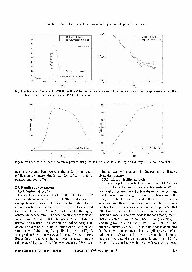
2.3. Results and discussions2.3.1. Stable jet profiles
The stable jet radius profiles for both PIB/PB and PEO/
water solutions are shown in Fig. 1. The results from the
asymptotic analysis with solutions of the full stable jet gov-
erning equations are shown for the PIB/PB Boger fluid
(see Carroll and Joo, 2008). We note that for the highly
conducting, viscoelastic PEO/water solution the visoelastic
force as well as the inertial force needs to be included to
balance the electrical force term in the final boundary con-
dition. The difference in the evolution of the viscoelastic
stress of two fluids along the spinline is shown in Fig. 2.
It is predicted that the viscoelastic stress for the PIB/PB
Boger fluid is relaxed as the jet moves far away from the
spinneret, while that of the highly viscoelastic PEO/water
solution steadily increases with increasing the distance
from the spinneret.
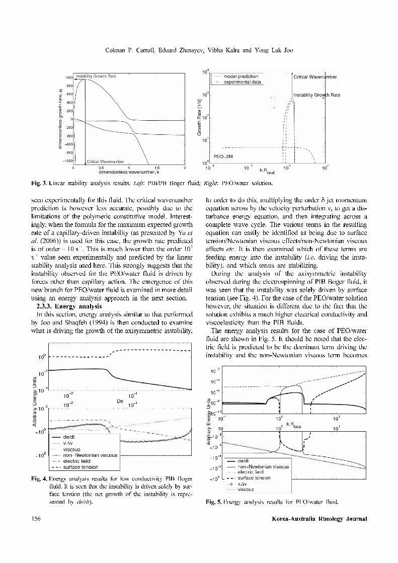
2.3.2. Linear stability analysis
The next step in the analysis is to use the stable jet data
as a basis for performing a linear stability analysis. We are
principally interested in extracting the maximum ω value,
and the wavenumber, kcritical. The values obtained using the
analysis can be directly compared with the experimentally-
observed growth rates and wavenumbers. The dispersion
relation for two fluids is shown in Fig. 3. It is predicted that
PIB Boger fluid has two distinct unstable axisymmetric
instability modes. The first mode is the ‘conducting mode’
that is unstable at low wavenumber (i.e. long wavelength),
and the growth rate is close to zero. Due to the low elec-
trical conductivity of the PIB fluid, this mode is dominated
by the other unstable mode, which is capillary-driven (Car-
roll and Joo, 2008). For the PEO/water solution, the max-
imum growth rate of the most unstable branch is ~103 s−1,
which is very consistent with the growth rates of the beads
Fig. 1. Stable jet profiles. Left: PIB/PB Boger fluid (The inset is the comparison with experimental data near the spinneret.), Right: Sim-
ulation and experimental data for PEO/water solution.
Fig. 2. Evolution of axial polymeric stress profiles along the spinline. Left: PIB/PB Boger fluid, Right: PEO/water solution.
Colman P. Carroll, Eduard Zhmayev, Vibha Kalra and Yong Lak Joo
156 Korea-Australia Rheology Journal
seen experimentally for this fluid. The critical wavenumber
prediction is however less accurate, possibly due to the
limitations of the polymeric constitutive model. Interest-
ingly, when the formula for the maximum expected growth
rate of a capillary-driven instability (as presented by Yu et
al. (2006)) is used for this case, the growth rate predicted
is of order ~10 s−1. This is much lower than the order 103
s−1 value seen experimentally and predicted by the linear
stability analysis used here. This strongly suggests that the
instability observed for the PEO/water fluid is driven by
forces other than capillary action. The emergence of this
new branch for PEO/water fluid is examined in more detail
using an energy analysis approach in the next section.
2.3.3. Energy analysis
In this section, energy analysis similar to that performed
by Joo and Shaqfeh (1994) is then conducted to examine
what is driving the growth of the axisymmetric instability.
In order to do this, multiplying the order δ jet momentum
equation across by the velocity perturbation vε to get a dis-
turbance energy equation, and then integrating across a
complete wave cycle. The various terms in the resulting
equation can easily be identified as being due to surface
tension/Newtonian viscous effects/non-Newtonian viscous
effects etc. It is then examined which of these terms are
feeding energy into the instability (i.e. driving the insta-
bility), and which terms are stabilizing.
During the analysis of the axisymmetric instability
observed during the electrospinning of PIB Boger fluid, it
was seen that the instability was solely driven by surface
tension (see Fig. 4). For the case of the PEO/water solution
however, the situation is different due to the fact that the
solution exhibits a much higher electrical conductivity and
viscoelasticity than the PIB fluids.
The energy analysis results for the case of PEO/water
fluid are shown in Fig. 5. It should be noted that the elec-
tric field is predicted to be the dominant term driving the
instability and the non-Newtonian viscous term becomes
Fig. 3. Linear stability analysis results. Left: PIB/PB Boger fluid; Right: PEO/water solution.
Fig. 4. Energy analysis results for low conductivity PIB Boger
fluid. It is seen that the instability is driven solely by sur-
face tension (the net growth of the instability is repre-
sented by de/dt). Fig. 5. Energy analysis results for PEO/water fluid.
Nanofibers from electrically driven viscoelastic jets: modeling and experiments
Korea-Australia Rheology Journal September 2008 Vol. 20, No. 3 157
destabilizing in the wavenumber interval 1<k.Rlocal <2.5,
rapidly pushing energy into the instability. The electric
field term in the energy analysis emanates from the electric
force term in the jet momentum equation. For the case of
the PIB Boger fluid, the energy analysis results show that
the term resulting from the coupling between the surface
charge and electric field is the most important one. This
term is seen to be stabilizing. For the PEO/water systems
however, much larger surface charge densities are present
(since the electrical conductivity is much larger and σ∝1/
Pe). This leads to a dominant surface charge term, which
is a destabilizing influence for this case. It thus appears that
interaction between the charges on the jet with an aid of
viscoelasticity is driving the instability.
3. Modeling of nonisothermal polymer jets in meltelectrospinning
While most of previous work on electrospinning has
involved polymer solutions, much progress has also been
made in polymer melt electrospinning (Zhou et al., 2006).
The latter is more attractive for industrial applications
because it is environmentally benign, it eliminates the sol-
vent recovery and treatments costs, and there is a wider
selection of polymers available, including such important
systems as polyethylene (PE) and polypropylene (PP)
which do not have appropriate solvents at room temper-
ature. Besides above advantages, this solvent-free approach
also opens the door to theoretical routes to model elec-
trospinning without the complications associated with sol-
vent evaporation.
In the current study, we extend the previous treatment by
Carroll and Joo (2006) to the case of nonisothermal poly-
mer melt jet and compare the simulation results to exper-
iments on polylactic acid (PLA).
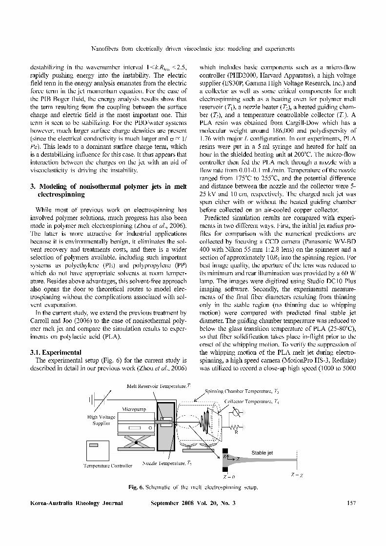
3.1. ExperimentalThe experimental setup (Fig. 6) for the current study is
described in detail in our previous work (Zhou et al., 2006)
which includes basic components such as a micro-flow
controller (PHD2000, Harvard Apparatus), a high voltage
supplier (ES30P, Gamma High Voltage Research, Inc.) and
a collector as well as some critical components for melt
electrospinning such as a heating oven for polymer melt
reservoir (T1), a nozzle heater (T2), a heated guiding cham-
ber (T3), and a temperature controllable collector (T4). A
PLA resin was obtained from Cargill-Dow which has a
molecular weight around 186,000 and polydispersity of
1.76 with major L configuration. In our experiments, PLA
resins were put in a 5 ml syringe and heated for half an
hour in the shielded heating unit at 200oC. The micro-flow
controller then fed the PLA melt through a nozzle with a
flow rate from 0.01-0.1 mL/min. Temperature of the nozzle
ranged from 175oC to 255oC, and the potential difference
and distance between the nozzle and the collector were 5-
25 kV and 10 cm, respectively. The charged melt jet was
spun either with or without the heated guiding chamber
before collected on an air-cooled copper collector.
Predicted simulation results are compared with experi-
ments in two different ways. First, the initial jet radius pro-
files for comparison with the numerical predictions are
collected by focusing a CCD camera (Panasonic WV-BD
400 with Nikon 55 mm 1:2.8 lens) on the spinneret and a
section of approximately 10R0 into the spinning region. For
best image quality, the aperture of the lens was reduced to
its minimum and rear illumination was provided by a 60 W
lamp. The images were digitized using Studio DC10 Plus
imaging software. Secondly, the experimental measure-
ments of the final fiber diameters resulting from thinning
only in the stable region (no thinning due to whipping
motion) were compared with predicted final stable jet
diameter. The guiding chamber temperature was reduced to
below the glass transition temperature of PLA (25-80oC),
so that fiber solidification takes place in-flight prior to the
onset of the whipping motion. To verify the suppression of
the whipping motion of the PLA melt jet during electro-
spinning, a high speed camera (MotionPro HS-3, Redlake)
was utilized to record a close-up high speed (1000 to 5000
Fig. 6. Schematic of the melt electrospinning setup.

Colman P. Carroll, Eduard Zhmayev, Vibha Kalra and Yong Lak Joo
158 Korea-Australia Rheology Journal
frames per second) movie of the PLA melt jet near the col-
lector at various spinning temperatures. The resulting fiber
mat is then inspected in a LEICA 440 scanning electron
microscope (SEM) and the images are analyzed to deter-
mine the fiber size and distribution.
3.2. TheoreticalWe have developed a model for non-isothermal, free sur-
face flows of electrically charged viscoelastic fluids in the
stable jet region of the melt electrospinning process. The
model is based on thin filament approximation applied to
fully coupled momentum, continuity, and energy equa-
tions, Gauss' law, and the non-isothermal Giesekus con-
stitutive model. We have developed a new asymptotic jet
thinning relationship for polymer melts particularly under
non-isothermal conditions where the tensile force balances
the tangential electric force. The resulting system of equa-
tions is solved numerically. We refer the reader to our
recent publication for more details on nonisothermal
modeling of electrospinning (Zhmayev et al., 2008).
3.3. Results and discussionsTo validate our nonisothermal model, simulations are
compared to results of PLA melt electrospinning in two
different ways. First, the simulated initial jet profiles are
compared to digitized experimental images of the stable
melt jet near the spinneret. Secondly, the predicted effects
of melt temperature, flow rate, and electric field strength
on the final jet diameter are compared to the final average
fiber diameter from non-isothermal experiments where the
whipping motion is suppressed by rapid cooling.
3.3.1. Comparison of initial PLA melt jet profile
The simulated initial jet profiles are compared to digi-
tized experimental images of the stable melt jet near the
spinneret. As shown in Fig. 7, the agreement is good
throughout the initial rapid thinning region for various noz-
zle spinning temperatures. It is interesting to note that even
the current 1-D model is accurately capturing the initial jet
development under various nonisothermal conditions.
3.3.2. Comparison with final average fiber diameter
Fig. 8 shows the effect of nozzle temperature T2 on the
final jet diameter for both simulation and PLA melt elec-
trospinning experiments. The micrograph images of col-
lected PLA fibers are also shown as insets. We note that
the average fiber diameter from experiments in Fig. 8 is
much larger than that of typical melt electrospun fibers
because the additional thinning by the whipping motion
was suppressed by low spinning temperature. Under these
processing conditions, it is observed that average fiber
diameter is close to the predicted final stable jet diameter
and both predicted final jet diameter and average diameter
of collected PLA fibers decrease, as nozzle temperature
increases. It is observed that the increase in nozzle (melt)
temperature decreases the viscoelasticity (and viscosity),
and thus the final jet gets thinner with increasing nozzle
temperature. The predicted final jet diameter and average
fiber diameter from experiments at various flow rates and
electric field strengths are also shown in the figure. As the
flow rate decreases and the electrical field strength
increases, both predicted final jet diameter and average
diameter of experimentally collected fibers decrease.
4. Control of nanoparticle location via confinedassembly of block copolymers during elec-trospinning
Controlling the spatial location of nanoparticles (NPs) in
polymer matrices is the fundamental challenge surrounding
the development of high end polymer nanocomposite
materials. High particle surface energies and strong inter-
particle interactions often lead to the aggregation of par-
ticles making it difficult to control their location. One can
use block copolymers (BCP) as templates for guiding the
location of nanoparticles for sophisticated tailoring of the
overall nanocomposite properties (Balazs et al., 2006).
Although surface modification has played an important
role in guiding NPs at desired locations in block copol-
ymers for many metals like gold and silver, in case of mag-
netically active particles like magnetite, strong magnetic
dipole interactions between particles often lead to clus-
tering and aggregation (Harris et al., 2003). Magnetite can
display high saturation magnetization and resistance to oxi-
dation, attracting great interest in electrical and biomedical
applications. Park and Char (2006) exploited the selectivity
of film casting solvents to control the morphology of mag-
Fig. 7. Comparisons of simulated and experimental initial jet pro-
files at various melt temperatures, T2=215oC, 235oC, and
255oC. We kept T3=25oC, E=2.0 kV/cm, and Q=0.05
ml/min for all three cases.

Nanofibers from electrically driven viscoelastic jets: modeling and experiments
Korea-Australia Rheology Journal September 2008 Vol. 20, No. 3 159
netic nanoparticle/poly(styrene-block-isoprene) (PS-b-PI)
nanocomposite films. For solvents like THF and toluene
which are neutral for PS and PI, they reported the for-
mation of lattice like NP aggregates inducing a BCP phase
transition from cylindrical to spherical morphology. In con-
trast, for PI selective solvents like hexane, NPs were selec-
tively incorporated into the PI phase for up to 5 wt%
nanoparticles in neat BCP. For higher particle loading,
however, aggregates were formed and selectivity of NPs
was lost.
Previous studies have been limited to the use of BCP cast
films as particle guiding scaffolds. The objective of this
paper is to use BCP nanofibers as templates to control the
location of nanoparticles not only to obtain high surface
area functional nanofiber mats, but also to achieve higher
particle loading owing to different fabrication conditions
compared to those for cast films. To this end, we have used
electrospinning to incorporate magnetite nanoparticles cov-
ered with oleyl group in lamellar forming PS-b-PI nanofi-
bers. Electrospinning is a simple and versatile method that
uses strong electric field to draw polymer solutions or
melts to produce ultra thin fibers with diameters ranging
from 50 to 500 nm. Recently, we reported the formation of
highly ordered lamellar morphology in pure BCP elec-
trospun fibers encapsulated with silica shell using coaxial
electrospinning. Thermally stable silica shell allowed us to
anneal the fibers above glass transition temperature of BCP
and obtain equilibrium morphology (Kalra et al., 2006a;
2006b). Lamellar structures in the form of stacked discs
and alternate concentric rings of PS and PI are formed
owing to the elongational deformation during electrospin-
ning and cylindrical confinement of the BCP. The work on
confined assembly in nanofibers is scientifically interest-
ing, but from the material applications perspective, it is
extremely important to be able to functionalize them. In the
present work, we have demonstrated how to utilize con-
Fig. 8. Effect of nozzle temperature, applied voltage, and flow rate on fiber diameter. The simulated final fiber diameter and average
diameter of collected PLA fibers are plotted at various nozzle temperatures, applied voltages, and flow rates.

Colman P. Carroll, Eduard Zhmayev, Vibha Kalra and Yong Lak Joo
160 Korea-Australia Rheology Journal
fined assembly to effectively functionalize these fibers
with magnetic nanoparticles to develop materials for novel
applications such as magnetic storage media, catalysis and
bioseparations. We show that due to the inherent fast evap-
oration and strong deformation rates in the electrospinning
process, the particles preferentially wet the PI domain and
yet remain very monodisperse for much higher particle
fractions than in BCP/magnetic NP films.
We also present molecular dynamics simulations coupled
with a dissipative particle dynamics thermostat to model
and simulate the behavior of symmetric diblock copoly-
mer/nanoparticle systems under simple shear flow. We
consider self-attracting nanoparticles to mimic magnetites
used in the electrospinning study. The aim of our present
study is to understand how the self-attracting nanoparticles
disperse in a block copolymer system under shear flow and
how the presence of nanoparticles affects the rheology,
structure and flow behavior of block copolymer systems.
4.1. ExperimentalPS-b-PI with MPS=53500 g/mol and MPI=70000 g/mol
is synthesized using a two step living anionic polymer-
ization (Kalra et al., 2006a). The polydispersity of the
polymer obtained by gel permeation chromatography is
1.04. Transmission Electron Microscopy (TEM) and small
angle x-ray scattering (SAXS) studies were carried out to
show the formation of lamellar morphology in films of PS-
b-PI cast in THF. Monodisperse 4.1±0.55 nm magnetite
nanoparticles with surface coated with oleyl group were
synthesized using a method similar to the one demon-
strated by Sun and Zeng (2002). 2 mmol of Iron (III) acety-
lacetonate (Fe(acac)3) was mixed in 20 ml of octadecene
with 1,2-hexadecanediol (10 mmol), oleic acid (6 mmol),
and oleylamine (6 mmol) under nitrogen and heated to 285oC for 30 min (ramping rate: 3oC/min). The precipitated
magnetite nanoparticles by cooling were recovered by cen-
trifugation. The presence of oleyl group on the surface of
particles makes them marginally selective towards PI
phase of the BCP. Coaxial nanofibers were electrospun
using 15-17 wt% solution of PS-b-PI/Fe3O4 NP mixtures in
THF as the inner core and silica sol gel precursor as the
outer solution. NP weight fractions in solid polymer were
varied from 0-10%. The volumetric flow rates used for
inner and outer solutions were 0.02 ml/min and 0.03 ml/min
respectively. The fibers were spun at an electric potential of
20 kV with spinneret to collector distance of 4 inches. We
refer the reader to our recent publications for a more
detailed overview of the experimental setup (Kalra et al.,
2006b). The diameters of coaxially spun fibers range from
300 nm to 1 µm as examined by Scanning Electron
Microscopy (SEM) (Leo 1550) with the core diameter typ-
ically ranging from 200-500 nm. Fibers, embedded in
epoxy matrix, were microtomed into 60 nm thin cross-sec-
tional and longitudinal sections at room temperature using
Leica ultracut UCT. Fiber sections were stained in osmium
tetraoxide vapors for 10 min and were viewed under Tec-
nai T12 transmission electron microscope operated at 120
KV for further characterization.
4.2. Theoretical modeling and simulationCoarse-grained Molecular Dynamics has been used to
simulate the motion of self-attracting NPs in block copoly-
mer and homopolymer melts. We refer the reader to our
recent publication for more details on the simulation
method (Kalra et al., 2008). The copolymer and homo-
polymer chains in the current study are modeled as fully
flexible bead-spring chains where the monomers are never
allowed to overlap. Since we are dealing with a diblock
copolymer, the chains consist of “A” and “B” blocks of
monomers. The excluded volume interactions between the
A and B monomers are accounted for by the purely repul-
sive, cut and shifted, Lennard-Jones (LJ) potential which is
often referred to as the WCA potential. We use a slight
modification of the Lennard Jones potential (refer to
equation 4 in Kalra et al., 2008) to model interactions
between different components of each system studied.
Equation 4 generates an attractive potential tail for all non
zero k values. Table 3 gives details of potentials for three
systems studied in this paper. Polymers are modeled as
flexible bead- spring chains with a FENE (Finitely Exten-
sible Nonlinear Elastic) potential and shear is implemented
using Lee Edwards Periodic Boundary Conditions with the
SLODD algorithm. To incorporate the physics of micro-
scopic phase separation between the A and B species, we
utilize an attractive potential between like monomers (i.e.,
A-A or B-B). This interaction taken together with the repul-
sive A-B potential ensures that phase separation will occur
if the temperature is below the order-disorder transition
temperature. We use the same attractive potential that was
used by Horsch and coworkers to model the equilibrium
properties of diblock copolymer melts. In modeling the
nanoparticles, we mimic the work that was recently
reported by Schultz et al. (2005). They used a “discon-
tinuous” molecular dynamics (DMD) technique to first
Table 3. Summary of interactions in systems studied. For a block
copolymer nanocomposite A and B denotes two different
monomeric beads and P denotes the nanoparticle
I Block Copolymer
k=0 A-B,B-P
k=0.5 A-P,A-A, B-B
k=1.0 P-P
II Homopolymer k=0 A-P, A-A, P-P
III Homopolymerk=0 A-P, A-A
k=0 P-P

Nanofibers from electrically driven viscoelastic jets: modeling and experiments
Korea-Australia Rheology Journal September 2008 Vol. 20, No. 3 161
model the equilibrium structure of diblock copolymer
melts, and then to model the equilibrium behavior of BCP/
NP mixtures. In DMD, all of the interactions are repulsive
and phase separation is induced by repulsive shoulders
between unlike species. In our simulation methodology, to
model mignetites which are selectively attractive to PI
domain, the attractive potential is used for NP-NP and NP-
B interactions, while the repulsive potential is used
between A-B, and NP-A interactions. Finally, we used a
thermostat that preserves hydrodynamic interactions, i.e.,
the Dissipative Particle Dynamics (DPD) thermostat. The
detailed simulation parameters are summarized in Table 4.
4.3. Results and discussionsFig. 9 a) shows the TEM images of cross-section and
longitudinal section of microtomed fibers that were elec-
trospun using a solution of neat PS-b-PI in THF as the core
material. All samples in this study use silica precursor
solution as the shell material. After annealing well above
the glass transition temperature of the block copolymer,
alternating concentric rings of PS (unstained, light regions)
and PI (stained dark regions) are formed due to the cylin-
drical confinement of the silica shell. For 4 wt% NPs in
symmetric PS-b-PI (Fig. 9 b)), well-ordered alternate con-
centric rings of PS and PI have been shown with magnetite
NPs uniformly dispersed in the PI domain. For 10-15 wt%
NPs, a transition of morphology has been seen from con-
centric rings to a bicontinuous phase with NPs again uni-
formly dispersed in the PI domain (see Fig. 9 c)). It should
be noted that NPs still remain uniformly and selectively
dispersed in the PI phase in spite of high particle loading
in BCP. Nanofiber mats with bicontinuous assembly and
well dispersed NPs in one domain can be useful in fab-
rication of membrane materials with well connected pore
structure after selective etching of the other domain.
To further understand the effect of flow on the nano-
Table 4. Simulation parameters used in the study
Parameters SymbolValue
(MD units)
Temperature kBT 1
NP,monomer size σP, σ 1
NP,monomer mass m 1
Chain length N 10
Bead density ρ 0.85
Cubic box size L 26-36
NP fraction φP 0.1
Number of chains M 1341-3600
Flory Huggins parameter*N20 χN 53.3
MD integration time step ∆t 0.01
Domain spacing d ~9.1
Copolymer end to end distance R0 4.62
Shear rate 0-0.15γ·
Fig. 9. TEM images of microtomed coaxial nanofibers. a) neat PS-b-PI, b) PS-b-PI with 4 wt% magnetite, and c) PS-b-PI with 10 wt%
magnetite. Top row is the cross section, while the cut along the fiber direction is shown in the bottom row. Grey shell region
is silica, in the core, light regions are PS domains, dark regions are stained PI domains and even darker dots are magnetite NPs.
All scale bars are 200 nm.

Colman P. Carroll, Eduard Zhmayev, Vibha Kalra and Yong Lak Joo
162 Korea-Australia Rheology Journal
particle location in block copolymers, we have performed
coarse grained MD simulations under simple shear flow.
Snapshots of MD simulation for self attracting nanopar-
ticles in BCP (System I) without and with shear are shown
in Fig. 10. The concentration profiles for NP, A and B
domains under shear are also shown in the figure. As
expected, self-attracting NPs with preferred interaction
with the B domain form aggregate in the B domains under
equilibrium, preventing symmetric BCP from assembling
into lamellae. When deformation is applied, self-attracting
NPs are dispersed in the B domain, placing themselves
near the center of the B domain. These results suggest that
deformation can play an important role in controlling the
location of nanoparticles in block copolymer matrices, and
that strong deformation during electrospinning can be one
of the reasons why much higher particle fractions than in
BCP/magnetic NP films are uniformly dispersed in the PI
domain of electrospun BCP fibers.
The effect of shear can be divided into two parts; the first
is the deformation that leads to an increase in the inter-par-
ticle distance and slows down the aggregation, the second
is the effect of shear on diffusion constants of the nano-
particles. While the former would always work towards
preventing aggregates, the latter could cause both homog-
enization and faster aggregation. In this case, a delicate
balance of various factors such as shear rate, and inter-
action potentials will be required. To understand these
effects of shear and provide a tool for targeted experiments,
we studied a simpler case of homopolymer with nano-
particles. Furthermore, to isolate the effect of diffusion on
aggregation, we use systems with different chain length of
the polymer matrix. Fig. 11 shows mean squared dis-
placement of nanoparticles vs. time curves for System II at
zero shear and shear rate=0.1 MD units. As seen in the
figure, the NPs diffuse at the similar rate (slope of the
curve) at zero shear in spite of the large differences in the
melt viscosity of different polymer chain lengths. This
interesting result is in line with a previous theory which
says that small particles (less than tube diameter) in a poly-
mer melt experience the same friction as in a melt of
monomer units. However, for shear rate=0.1, we find that
the diffusion decreases with increasing chain length. We
hypothesize that under shear flow the particles span a
larger portion of the polymer chain and hence are slowed
down due to the presence of entanglements. This effect of
shear on particle diffusion is critical in understanding and
designing an optimum well dispersed particle system. In
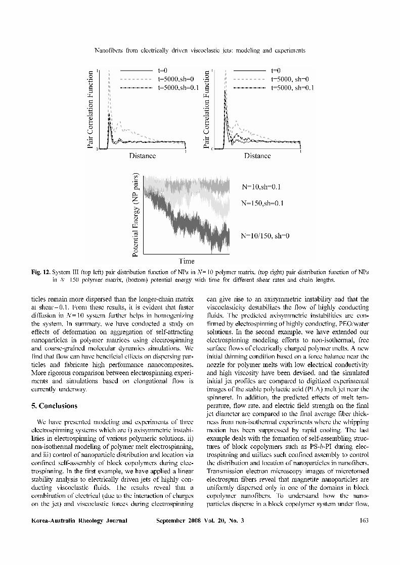
Fig. 12, we quantify our results through the pair distri-
bution function (g(r)). The initial g(r) shows only one peak
indicating a uniformly dispersed system. For both N=10
and N=150 polymer systems, we find that after t=5000
MD units, NPs in systems under shear remain much more
dispersed than quiescent systems. As expected from the
diffusion rates in Fig. 11, g(r) for both N=10 and N=150
systems show the same trend with time at shear=0. In
addition, we find that for the shorter-chain matrix, the par-
Fig. 10. Snapshots of MD simulation results for self attracting particles in BCP (system I). left: no shear, middle: shear rate=0.02, right:
Concentration profiles for NP, A and B domains under shear.
Fig. 11. Mean squared displacement of NPs vs. time for System
II for different chain length(N) and shear rates(sh).
Nanofibers from electrically driven viscoelastic jets: modeling and experiments
Korea-Australia Rheology Journal September 2008 Vol. 20, No. 3 163
ticles remain more dispersed than the longer-chain matrix
at shear=0.1. From these results, it is evident that faster
diffusion in N=10 system further helps in homogenizing
the system. In summary, we have conducted a study on
effects of deformation on aggregation of self-attracting
nanoparticles in polymer matrices using electrospinning
and coarse-grained molecular dynamics simulations. We
find that flow can have beneficial effects on dispersing par-
ticles and fabricate high performance nanocomposites.
More rigorous comparison between electrospinning experi-
ments and simulations based on elongational flow is
currently underway.
5. Conclusions
We have presented modeling and experiments of three
electrospinning systems which are i) axisymmetric instabi-
lities in electrospinning of various polymeric solutions, ii)
non-isothermal modeling of polymer melt electrospinning,
and iii) control of nanoparticle distribution and location via
confined self-assembly of block copolymers during elec-
trospinning. In the first example, we have applied a linear
stability analysis to electrically driven jets of highly con-
ducting viscoelastic fluids. The results reveal that a
combination of electrical (due to the interaction of charges
on the jet) and viscoelastic forces during electrospinning
can give rise to an axisymmetric instability and that the
viscoelasticity destabilizes the flow of highly conducting
fluids. The predicted axisymmetric instabilities are con-
firmed by electrospinning of highly conducting, PEO/water
solutions. In the second example, we have extended our
electrospinning modeling efforts to non-isothermal, free
surface flows of electrically charged polymer melts. A new
initial thinning condition based on a force balance near the
nozzle for polymer melts with low electrical conductivity
and high viscosity have been devised, and the simulated
initial jet profiles are compared to digitized experimental
images of the stable polylactic acid (PLA) melt jet near the
spinneret. In addition, the predicted effects of melt tem-
perature, flow rate, and electric field strength on the final
jet diameter are compared to the final average fiber thick-
ness from non-isothermal experiments where the whipping
motion has been suppressed by rapid cooling. The last
example deals with the formation of self-assembling struc-
tures of block copolymers such as PS-b-PI during elec-
trospinning and utilizes such confined assembly to control
the distribution and location of nanoparticles in nanofibers.
Transmission electron microscopy images of microtomed
electrospun fibers reveal that magnetite nanoparticles are
uniformly dispersed only in one of the domains in block
copolymer nanofibers. To understand how the nano-
particles disperse in a block copolymer system under flow,
Fig. 12. System III (top left) pair distribution function of NPs in N=10 polymer matrix, (top right) pair distribution function of NPs
in N=150 polymer matrix, (bottom) potential energy with time for different shear rates and chain lengths.

Colman P. Carroll, Eduard Zhmayev, Vibha Kalra and Yong Lak Joo
164 Korea-Australia Rheology Journal
coarse-grained molecular dynamics simulations coupled
with a dissipative particle dynamics thermostat have been
carried out. Our simulation results confirm our electro-
spinning experiments that deformation can be used as a
parameter to effectively control nanoparticle location and
distribution.
References
Balazs, A. C., T. Emrick and T. P. Russell, 2006, Nanoparticle poly-
mer composites: where two small worlds meet, Science 314, 1107.
Carroll, C. P. and Y. L. Joo, 2006, Electrospinning of viscoelastic
Boger fluids: modeling and experiments, Phys. Fluids 18,
053102.
Carroll, C. P. and Y. L. Joo, 2008, Axisymmetric instabilities in
electrically driven viscoelastic fluid jets: modeling and
experiments, J. Non-Newt. Fluid Mech. 153(2-3), 130.
Fong, H. and D. H. Reneker, 2001, “6. Electrospinning and the
formation of nanofibers,” in: D.R. Salem (Ed.) Structure
formation in polymeric fibers, Munich: Hanser Gardner Pub-
lications, 225-246.
Harris, L. A., J. D. Goff, A. Y. Carmichael, J. S. Riffle, J. J. Har-
burn, T. G. St. Pierre and M. Saunders, 2003, Magnetite nano-
particle dispersions stabilized with triblock copolymers, Chem.
Mater. 15, 1367.
Hohman M. M., M. Shin, G. Rutledge and M. P. Brenner, 2001,
Electrospinning and electrically forced jets: I. Stability theory,
Phys. Fluids 13, 2201.
Huang, Z. M., Y. Z. Zhang, M. Kotaki and S. Ramakrishna, 2003,
A review on polymer nanofibers by electrospinning and their
application in nanocomposites, Composites Sci. & Tech. 63, 2223.
Jaeger R., H. Schönherr and G. J. Vaneso, 1996, Chain packing
in electro-spun poly(ethylene oxide) visualized by atomic force
microscopy, Macromolecules 29, 7634.
Joo Y. L. and E. S. G. Shaqfeh, 1994, Observations of purely
elastic instabilities in the Taylor-Dean flow of a Boger fluid, J.
Fluid Mech. 262, 27.
Kalra, V., P. A. Kakad, S. Mendez, T. Ivannikov, M. Kamperman
and Y. L. Joo, 2006, Self-assembled structures in electrospun
PS-b-PI fibers, Macromolecules 39, 5453.
Kalra, V., S. Mendez, J. H. Lee, H. Nguyen, M. Marquez and Y.
L. Joo, 2006, Confined assembly in coaxially electrospun
block-copolymer fibers, Adv. Mater. 18, 3299.
Kalra, V., S. Mendez, F. Escobedo and Y. L. Joo, 2008, Coarse-
grained molecular dynamics simulation on the placement of
nanoparticles within symmetric diblock copolymers under
shear flow, J. Chem. Phys. 128, 164909.
Park, M. J. and K. Char, 2006, Effect of the casting solvent on the
morphology of PS-b-PI diblock copolymer/magnetite nano-
particle mixtures, Langmuir 22, 1375.
Reneker D. H., A. L. Yarin, H. Fong and S. Koombhongse, 2000,
Bending instability of electrically charged liquid jets of
polymer solutions in electrospinning, J. Appl. Phys. 87, 4531.
Son W. K., J. H. Youk, T. S. Lee and W. H. Park, 2004, The
effects of solution properties on electrospinning of ultrafine
poly(ethylene oxide) fibers, Polymer 45, 2959.
Sun, S. and H. Zeng, 2002, Size-controlled synthesis of mag-
netite nanoparticles, J. Am. Chem. Soc. 124, 8204.
Schultz, A. J., C. K. Hall and J. Genzer, 2005, Computer
simulation of block copolymer/nanoparticle composites, Mac-
romolecules 38, 3007.
Theron S. A., E. Zussman and A. L. Yarin, 2004, Experimental
investigation of the governing parameters in the electrospin-
ning of polymer solutions, Polymer 45, 2017.
Yu J. H., S. V. Fridrikh and G. C. Rutledge, 2006, The role of elas-
ticity in the formation of electrospun fibers, Polymer 47, 4789.
Zhmayev, E., H. Zhou and Y. L. Joo, 2008, Modeling of
nonisothermal polymer jets in melt electrospinning, J. Non-
Newt. Fluid Mech. 153(2-3), 95.
Zhou, H., T. Green and Y. L. Joo, 2006, The thermal effects on
electrospinning of polylactic acid melts, Polymer 47, 7497.