nanobiscuit vm95 reference manual...
TRANSCRIPT

NanoBiscuit Reference Manual – Version 1.1 © Erdman Video Systems, Inc. 2010
8895 SW 129th Street, Miami, FL 33176 Tel: 305.252.9560 | Fax: 305.969.9280
NanoBiscuit Hardware and VM95 Reference Manual
Version 1.0

NanoBiscuit Reference Manual – Version 1.1 2

NanoBiscuit Reference Manual – Version 1.1 3
Table of Contents 1. Hardware
1.1. Overview 1.2. Block Diagram 1.3. Power Requirements 1.4. Long Term Reliability Strategy 1.5. Components 1.6. Connections 1.7. Switches 1.8. Fuses 1.9. Transformer Box
2. Software 2.1. General Operation 2.2. The Main Screen 2.3. The Options
2.3.1. General 2.3.2. Pan & Tilt 2.3.3. Controller 2.3.4. Video 2.3.5. Digital Camera 2.3.6. Dial-up 2.3.7. FTP 2.3.8. Archive 2.3.9. Advanced 2.3.10. Weather/Email
3. Programming 3.1. The Sampling Schedule
3.1.1. -98 Scene – Digital Camera Acquisition 3.1.1.1. General Tab 3.1.1.2. Capture Tab 3.1.1.3. Overlay Tab 3.1.1.4. Archiving Tab
3.1.2. -99 Scene – AutoPan Image Capture 3.1.3. -997, -998, -995 – Uploading to the Internet
3.2. WVCC – Configuration for Video Enabled Systems 3.3. uEye Camera Considerations 3.4. Common Reprogramming Tasks
4. Index

NanoBiscuit Reference Manual – Version 1.1 4

NanoBiscuit Reference Manual – Version 1.1 5
Chapter 1
Hardware Overview and Strategies

NanoBiscuit Reference Manual – Version 1.1 6

NanoBiscuit Reference Manual – Version 1.1 7
1.1 Hardware Overview The Nano-Biscuit System is an internet appliance which uses a Windows XP computer and embedded support circuitry to create a reliable image monitoring and documentation system that can run unattended for months to years, while continuously taking images, archiving them and uploading them to the Internet. The main components of a complete system consist of the computer, watchdog circuitry, a digital camera with an environmental housing, support circuitry, power supplies and cabling.
1.2 System Block Diagrams
Fig 1.1 All-in-one Configuration
Fig 1.2 Two-Piece Configuration
NanoBiscuit Reference Manual – Version 1.1 8
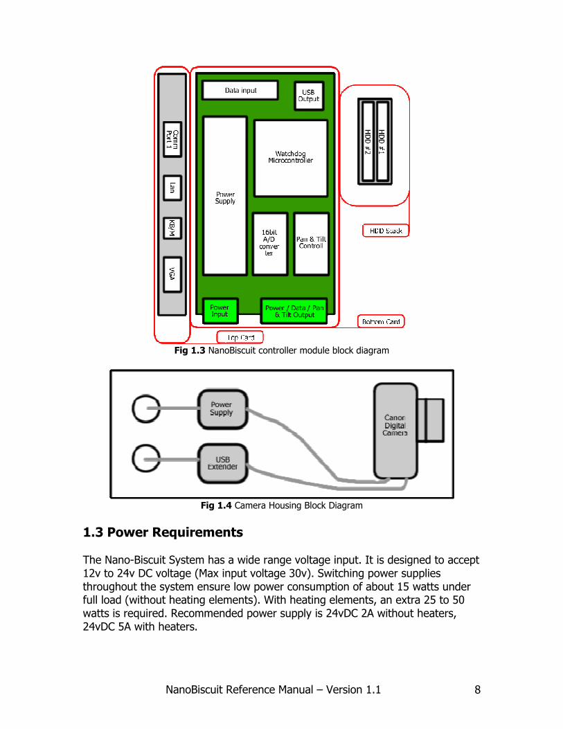
Fig 1.3 NanoBiscuit controller module block diagram
Fig 1.4 Camera Housing Block Diagram
1.3 Power Requirements The Nano-Biscuit System has a wide range voltage input. It is designed to accept 12v to 24v DC voltage (Max input voltage 30v). Switching power supplies throughout the system ensure low power consumption of about 15 watts under full load (without heating elements). With heating elements, an extra 25 to 50 watts is required. Recommended power supply is 24vDC 2A without heaters, 24vDC 5A with heaters.

NanoBiscuit Reference Manual – Version 1.1 9
1.4 Long Term Reliability and Maintenance Strategy There are a number of subsystems and features incorporated into the Nano-Biscuit to ensure reliable operation and remote maintenance. The Nano-Biscuit system incorporates an 8-bit 8051 microcontroller, henceforth called the Watchdog. The Watchdog performs various functions including power management, watchdog and A/D conversion. When the main power is switched on, power is first applied to the Watchdog. This starts its program running and within about 3 seconds, the Watchdog applies power to the embedded x86 computer. The embedded pc is setup to start running VM95 automatically. VM95 communicates to the Watchdog through a serial port and while VM95 is running properly, VM95 sends "okay" messages to the Watchdog. If the Watchdog does not receive an "okay" message at the predetermined expiration time (20 min default), it will do a cold restart of the embedded pc (by removing power and reapplying it after a few seconds). When the embedded pc starts up, besides launching VM95, it also launches a suite of remote access and control programs, a direct IP access program, a VPN program, and a hosted access program. This allows a remote user to reprogram, configure, and perform maintenance on the embedded pc via LAN/WAN connection. All Nano-Biscuit systems come with two mirrored hard disk drives. One of the drives is utilized as the system disk, the other is a backup. All images and configuration files are mirrored during normal operation of the system. In the event of a system disk failure (corruption, etc.) the watchdog will switch the hard disk drive configuration so that the backup becomes the new system disk. Once the disks are flipped in this manner the backup can be cloned back to the original system disk. This provides data backup and an extra layer of reliability. All internet connected Nano-Biscuit systems have, built into VM95, the ability to report system malfunction to the end user. These error messages can be sent via email or text message to multiple users. Maintenance: The system hardware should routinely be checked for cleanliness every 1 to 3 months depending on the location. Bird droppings, dust, frequent rain, icy conditions, and salty environments will hasten this requirement. Extension mops can be purchased at your local hardware store to give you the ability to wipe down the external housings of any debris. If operating the controller box indoors with the box open, be aware of any dust that may accumulate on the heatsink and remove periodically. Check screw cage clamp (green pluggable terminal) wiring at least once a year to ensure a tight connection. Check mounting bracket at least once a year for loose screws, attach points, or safety straps. Adjust as needed. If operating with UPS battery backup,

NanoBiscuit Reference Manual – Version 1.1 10
be sure to follow the manufacturers recommended battery replacement schedule.
1.5 Hardware Components Embedded x86 Computer: This component is what’s called an embedded pc available from Advantech (www.advantech.com), model 9375 or equivalent. It utilizes a low power x86 microprocessor, which runs at 500 MHz or greater. It is a very low power computer requiring approximately 5w to 10w of power. Most systems will come with 512MB of Ram and two 160GB 2.5” notebook hard disk drive. The computer has 4 serial ports, a parallel port and an Ethernet (RJ45 jack). Watchdog: This is an 8-bit microprocessor made by Atmel. (http://www.atmel.com/). It has 8K programmable flash and executes our custom firmware that performs a number of low level functions including power management, rebooting, A/D conversions, watchdog, voltage/temperature monitoring, and wake up alarm for the embedded pc. A/D Conversion Circuitry: Temperature measurements and pan tilt positioning are accomplished by reading voltages from the respective sensors. The voltages are converted to 16 bit integers and sent to the embedded pc via the serial port. Main Board: Our in-house designed and manufactured PCB. It’s approximately 4” x 7” and sits as the base board in the biscuit stack. Functional Switches and LED's: There are three functional switches on the Main Board. The “on/off” switch is used to tell the Watchdog that the unit is to be powered on. The “watchdog” switch enables or disables the watchdog expiration hard reboot. The third switch is a 4 pole dip switch which controls what voltage is being output to the camera. Ports and Connectors: All the ports to connect to the embedded pc are located on the edge of the board. This includes keyboard/mouse (shared 6 pin mini-din), monitor (VGA HDDB-15), and network (RJ/45). All external connections to the main board are through pluggable terminal strips. All the connections are labeled for convenience. Battery Backup: When possible, plugging the unit into a UPS battery backup is suggested for uninterrupted system function.

NanoBiscuit Reference Manual – Version 1.1 11
Pan/Tilt Controller: The pan/tilt controller consists of a single half bridge IC motor driver. USB Extender modules: All two piece units with a cable length longer than 15ft come with a USB extender module. These modules extend the USB signal up to 150ft or 330ft over cat5e twisted pair (depends which model you purchased). Camera Board: Our camera board is identical to the main board. The watchdog software is different, however, in order to control the camera functions. (This feature is sometimes not included in the basic systems) Heaters: The system can be outfitted with heaters to prevent fogging/icing of the camera housing glass. The heaters come thermostatically controlled so as to turn on at 80° F and turn off at 110° F. This keeps the camera housing temperature at or above 80° F during most of the operation. This temperature range is well above the highest average dew point in the contiguous US, and safe for the equipment. Heaters can also be placed inside the controller box in a 2-piece configuration. These heaters also come thermostatically controlled so as to turn on at 40° F and turn off at 60° F. This set of heaters protect the spindle based HDD from freezing temperatures. Enclosures: All our enclosures are outdoor rated. The power supply enclosure is made from UV stabilized ABS plastic and is rated NEMA 4X. The controller box enclosure is resin epoxy filled fiberglass and rated to NEMA 4X. All our camera enclosures are industry standard Pelco enclosures and are rated to NEMA 3R. In rare instances we use Conway camera enclosures which are rated to IP66.
1.6 Internal Connections There are a number of internal connections that the user will encounter while setting up the NanoBiscuit system. The user should familiarize themselves with the connections prior to system deployment. This will help keep stress and confusion in the field to a minimum.

NanoBiscuit Reference Manual – Version 1.1 12
Fig 1.5 x86 Embedded PC
User accessible connections: CN19=Comm1, CN23=LAN, CN14=Keyboard/Mouse, CN12=VGA
System connections: CN16=Comm2-4, CN2=Power, CN15+CN13=USB, CN11=IDE, CN8=reset All other connections are unused.
Embedded PC connections: The embedded PC has all the connections of a normal PC. These connections will allow you to connect a monitor, keyboard, mouse, and ethernet cable to the system for diagnostics and configuration. All the user connections are along the edge of the circuit board for easy access.

NanoBiscuit Reference Manual – Version 1.1 13
Fig 1.6 EVS mainboard connections
EVS mainboard connections: User serviceable connections include the dual USB ports, all the switches, all the fuses, and the last and most important are the double stack green pluggable terminals along the bottom edge of the card. These Phoenix connecters are where the external devices will wire into the controller. All of the green terminals will come labeled with pin functions. The green pluggable terminal blocks that come attached to the cable should not need to be removed in order to pass the cable through the conduit gland of the box.

NanoBiscuit Reference Manual – Version 1.1 14
Fig 1.7 Passing the green pluggable terminal through the cable gland
Connecting the Camera cables to the NanoBiscuit Controller: As mentioned above, the user will need to connect the camera cable to the NanoBiscuit controller upon receipt of the equipment. This is done first by passing the camera cable ends through the cable gland as depicted in Fig 1.7. Then the user must plug the cables into the correct ports on the NanoBiscuit mainboard. Most systems will come with a category 5 ethernet cable and a multi-conductor cable. The category 5 ethernet cable must not be plugged into the ethernet port on the x86 embedded PC. This connection will be made instead to a device called the USB super booster. In truth this cable carries the USB signal to the camera in the camera housing. The multi-conductor wire will come wired into a set of two green pluggable terminals. These terminals will plug into the right side 10p double stack green header. They will be labeled for both the top and bottom terminals. If using a video based controller, the RCA type plug will connect either at the top edge of the EVS mainboard or directly to the blue capture card connected to your system. Please note that the camera housing side of the wiring will be factory connected in 95% of all systems and will not need user manipulation. Connecting the power cable to the NanoBiscuit Controller: The power connection from the transformer box will come pre-wired into a 4pos green pluggable terminal. This will plug into the top level of the bottom-left double stack green header. Please note that the bottom level is reserved for internal wiring of an LCD monitor (optional).

NanoBiscuit Reference Manual – Version 1.1 15
1.7 Switches Power Switch: There is only one power switch on the EVS mainboard. This switch is a soft switch (no current passes through the switch.) Left position is “off”, right position is “on”. Watchdog Enable Switch: This switch tells the watchdog to monitor the system for crashes when in the “on” position. If the watchdog doesn’t receive the “OK” signal from VM95 within the set watchdog expiration time (default 20min) then the watchdog will shut the PC down. This switch should be in the “on” position during normal operation, and only switched off during system maintenance. Left position is “off”, right position is “on”. Camera Voltage DIP Switch: The camera voltage output can be set to different voltages by the DIP switch in the middle on the board (check fig 1.6 for reference).
1.8 Fuses and Circuit Protection There are three fuses on the EVS mainboard: one main fuse, one camera fuse, and one embedded PC fuse (see fig 1.6.) These fuses are subminiature radial fuses and can be replaced in the event that they are tripped. Fuses will trip in the event of over-voltage or over-current conditions. These conditions are as follows:
Fuse Overcurrent max Overvoltage max
Main fuse 5A 36.8VDC
Embedded PC fuse 5A 7.0VDC
Camera fuse 3A (may be 5A) 14.7VDC
Fig 1.8 Transient voltage protection ratings Contact EVS to receive replacement fuses.
1.9 Transformer Box Certain NanoBiscuit configurations will come with an external transformer box. The box is an ABS plastic enclosure made by Bud Industries. The transformer can come ready to wire to 110vAC or 220vAC via green pluggable terminal blocks. The output will either be 30vDC or 24vDC depending on the factory configuration by EVS. The output is protected by a 5A 3AG glass fuse. Input and output terminals are labeled for your convenience. There is pass-through connector for ethernet that may simplify wiring in some instances.

NanoBiscuit Reference Manual – Version 1.1 16
Fig 1.9 Inside look at the external transformer box.

NanoBiscuit Reference Manual – Version 1.1 17
Chapter 2
Software Options and Settings

NanoBiscuit Reference Manual – Version 1.1 18

NanoBiscuit Reference Manual – Version 1.1 19
Software
A licensed version of Windows XP is installed on the computer. VM95 software, written by Erdman Video Systems, is the main application software and manages the majority of the systems capabilities such as digital capture and uploads. Systems configured with video capture cards, including uEye cameras require the program WVCC to be running along with VM95.
2.1 General Operation of VM95 VM95 is a Visual Basic 6.0 application developed, written, and maintained by EVS over the past 15 years. There are 2 modes or states that the program can be in, “Manual” and “Automatic.” When the program starts up, a screen is presented that says, “Click for Manual Control”. If you click on it, you enter manual control. In the Manual mode, you can test, configure, and program the operation of VM95. You can also view images from the local archive (hard disk), setting up and displaying composite images (composite images are any group of images, and are most often used to display panoramas consisting of 2 or more images). From Manual mode, one can launch the Automatic mode (under the File menu). The menus at the top will disappear and be replaced by one menu choice, “Stop Automatic”, which when clicked on will send you back to Manual mode. Automatic mode runs the ‘scenes’ (operations) specified in the Sample Schedule. The metaphor used here is that of a ‘Scene’. ‘Scenes’ are sampled (executed) regularly throughout the day and have “On” and “Off” times during the day. For example, “Scene 1” can be setup to turn on at 6:30 am and take a picture every 20 minutes until the “Off” time at 17:30 in the afternoon. When this “Scene” is sampled/executed, it snaps an image, downloads it from the camera to the computer, labels it, and saves it (archives it) to the local hard disk (and optionally to other hard drives). There are settings for what size of image you want, the quality, amount of disk space to use for the scene etc., all of which will be discussed in detail later. Another “Scene” operation can be an upload to the Internet. Here the various settings will involve whether to send a thumbnail, which FTP site to send the image, the name the image file should have at the FTP site, etc. In all, there are about 8 different types of ‘Scenes’ one can setup in the Sample Schedule, each having their own daily “On”, “Off”, and “Interval” times plus many other parameters depending on the operation performed by the ‘Scene’. We have mentioned” , Image Capture, and Image Uploading. Other “Scenes”

NanoBiscuit Reference Manual – Version 1.1 20
include AutoPan Image Capture, Video Capture, measuring temperature and voltage, different types of Internet Uploading, and even rebooting the system. The Sampling Schedule (under the Setup menu) is where the scenes are setup. Information that is common to all scenes or independent of the scenes is setup in the ‘Options’ (also under the Setup menu). Here things like Station Name, cameras, FTP sites, Email warnings, and many other parameters can be configured. When everything is setup properly, automatic mode can be launched and the various scenes will be executed throughout the day according to the Sample Schedule. VM95 operates in conjunction with the EVS Board. This board controls the power to the computer and to the cameras, toggling them when necessary. The EVS Board also communicates through a serial port with the computer and serves as a ‘watchdog’ for the VM95 program.
2.2 The Main Screen
Fig 2.1 The main screen when you enter Manual mode. This screen is seen when the pan tilt
option has been selected. The left column of the screen changes depending on which options have been select, e.g., with or without video, with or without digital cameras and with or without
a pan tilt unit.
There are 4 main windows one can see above. The upper left window (in green) is used for displaying live video signals and is also used for temporarily holding images when they are being processed, as in the case of labeling and resizing

NanoBiscuit Reference Manual – Version 1.1 21
the image. The other 3 windows are image buffers. After acquiring and processing an image, it is loaded into one of these windows before it is archived. You can also load your own images into these windows. You can zoom in on the images in these 3 buffers simply by “drawing” a box (click the left mouse button, and while holding it down, move the mouse: you will see a box being drawn, and when you release the mouse button, the image will be zoomed to that portion). A zoomed image will have horizontal and vertical scroll bars to let you move about in the image. To zoom all the way out, press the “x” key on the keyboard. You can also see a full screen image by double clicking on the image. To return to the normal view, double click again on the full screen image. In addition, you can increase the brightness, contrast and sharpness of the image but pressing the “b”, “c” and “s” keys respectively. To reduce the brightness, contrast and sharpness, hold down the “Shift” key while pressing “b”, “c” or “s”. To return to the original setting, press the “r” key. Two more image attributes can be obtained by selecting one of the last 2 menu choices under the “View/Edit” menu. “Show Image Dimensions” and “Compute Image Brightness” can be very useful in certain cases. “Compute Image Brightness” performs a calculation on the image that gives you one number representing the average brightness of the image. The value goes from 0 (black) to 255 (white). There are a couple programmable settings in the Sample Schedule that, when acquiring images, allow you to specify the average brightness desired for the image to be captured. When making movies or time lapse sequences, having images of all the same brightness can enhance the view-ability of the sequence. You can test the scenes choosing ‘Test Capture and Label’ under the Test Capture menu. The image captured will be displayed in one of the 3 buffers. The last buffer you clicked on will be the buffer used for the new image. Below the bottom two buffers, there is space for a message. This is used to display the status of various operations and to display messages that can alert the user to unusual conditions. Below this status line are a few check boxes: “View Sample List”: During Automatic mode, a list of all the scenes to be sampled is displayed. Sometimes you don’t want to see this and you just want to see the images. Unchecking this box will hide this sample list. “Rotate Capture Windows”: In Automatic mode, a check in this box will load the captured images into successive buffers, so you would be able to see that last 3 images capture. This is convenient sometimes but can reduce system performance if you are capturing high resolution images, so it’s best to leave this unchecked for normal operations.

NanoBiscuit Reference Manual – Version 1.1 22
“Enable Internet”: This check box directly affects whether the system will attempt to do uploads to the Internet or not. If it is unchecked, the system will not attempt to connect to the internet, either in both Manual and Automatic mode. If you or the program attempt to upload to the Internet, and this box is not checked, you will see a message on the Status Line alerting you to this condition. “Run Minimized”: this should not be checked and has been removed from recent version of vm95.
2.3 The Options Form To pull up the “Options” form from Manual mode, click on “SetUp” and then on “Options”.
2.3.1 General Options
Fig 2.2 The “Options” form. This is the General Tab that one sees when first entering the
“Options” form. To see the other groups of options, click on the desired heading in the white list box in the upper left.
System Type: The Pan/Tilt option requires an EVS Controller board. Station Name: Use a sensible name here since it is used in all texting and email alerts. It is also used in the file name when selecting the Argus file format.

NanoBiscuit Reference Manual – Version 1.1 23
Enable Video Server (wvcc): Check this for video systems and uEye camera systems. Slow Frame Rates: This will lower the load on the cpu. Check the task manager to see if cpu usage is too high, and check this option if it is too high. Solar Powered System: This option changes the way some of the power saving features work. Most reboot conditions are ignored since the system will most likely shut down itself anyway. Log files are kept to a smaller size. The Watchdog time is set to 5 minutes (instead of 60 minutes). It is not essential to check this when using a solar system. Min brightness: This option tells the software to NOT save (ie., archive) any captured image (from an Olympus or Canon camera only) that has an average brightness less than the value you enter. Brightness values can range from 0 (black) to 255 (white). Typical day time images have an average brightness around 100 – 140. Night time images can be as low as 50 and still show some details. We recommend a value of about 40 to avoid having unsightly dark images on your web page that remain there until the next morning. Save Canon Images: This is a special way to snap and collect images for solar powered systems. While the computer is off, the Controller board snaps pictures on the digital camera. When the computer wakes up, the images on the memory card will be archived (and optionally labeled) to the hard disk as scene 5. Scene 5 must be set up properly. Long Exposure White Balance: used by EVS for special imaging needs. Use Constant IP: used by EVS for special configurations, normally not checked. Ethernet Adapter: used by EVS for special configurations, normally not checked. Cycle Cam power at startup: Normally not checked. If the CamPower (in uEye systems for example) is used to power the USB extender REX unit, sometimes its required to toggle the power to these units to get them to perform reliably. Check this box to do this. IR Illuminator Enable: used by EVS for special imaging needs.

NanoBiscuit Reference Manual – Version 1.1 24
Master Slave Disk Control: Available on with the EVS Controller board, this is a type of poor man’s disk mirroring and ensures that the system function normally even if the primary disk suffers a complete meltdown. 2 Fixed Serial Controllers: Normally not checked. Used in specially configured systems to control 2 digital cameras located more than 100’ apart. Check Pan/Tilt each time: Normally not checked. Used in very high winds conditions that can move the pan tilt. Digitize Enabled: Normally checked. On pan tilt systems, it’s sometimes useful to run the schedule without digitizing to see how it moves to the various positions. Internet Enabled: Normally checked. Un-checking this allows you to run through a schedule while skipping over the uploads. Note that there is also check box at the bottom of the main screen that is also labeled 'Enable Internet': It has the same function and is more accessible. Limit Image Uploads: used by EVS for special configurations, normally not checked Use temporary file name: This option causes the software to send all files (when doing an FTP) using a temporary file name and then renaming it once it’s all there. This addresses 2 issues: 1) For those viewing the web page that contains the uploading image, this option keeps the viewer from seeing a partial image on the web or from getting the 'x' where the image should be, since (assuming you're using a static filename) while the image is being uploaded, the image is not available for viewers who try to see it. 2) The other issue concerns FTP Servers, such as IIS Version 4, which do not allow overwriting a file if any web browser has viewed the image in the last few minutes, but, oddly enough, it will let you rename it. Ignore AC Power loss: used by EVS for special configurations, normally not checked Do not check for file existence during FTP: Normally not checked. Some FTP servers seem to disconnect the user when a specific file is looked for in an empty directory, and this causes an unsuccessful upload. Note that checking the box cannot hurt anything: At worst, a file is uploaded that was already uploaded previously. Enable automatic exposure adjustments for conditions of low light: used by EVS for special imaging needs.

NanoBiscuit Reference Manual – Version 1.1 25
Use (new) long Thumbnail names: This option is recommended for all new installation. Previous to version 51z, the thumbnail filenames created for Internet uploading used 8 character filenames, and since the date and time were encoded into the filenames, times were resolved only to the minute. With this box checked, thumbnail filenames use the same name as the high resolution file, with '_tn' appended to the end. This could create problems if you already have old thumbnails uploaded, in that, for example, slide shows may not work properly anymore. Move Zoom before capture: used by EVS for special imaging needs.
2.3.2 Pan Tilt Options
Fig 2.3 Pan Tilt options allow you to correct (in software) for various types of wiring in which either the motor wires or the feedback pot wires are reversed.
When setting up a pan tilt system for the first time, it is necessary to make sure the software can move the unit in the direction it expects. That is to say, when clicking on the “Right” button, the unit actually pans to the right. If the unit moves to the left when “Right” is clicked, you simply check the “Reverse Pan Direction” box (see Fig 2.3) and “Right” becomes right. Likewise for the tilt; you must ensure that “Up” is up and “Down” moves down. Position of the pan tilt unit is read by measuring the voltage across potentiometers that are mechanically coupled to the gears of the pan tilt unit. A

NanoBiscuit Reference Manual – Version 1.1 26
reference voltage (of about 2 volts) is applied to the pots and the wiper gives us the position. Similarly to the pan and tilt motors, these can be wired differently relative to what the software expects. When the unit pans to the right, the readings should increase. You verify this by reading the current values (clicking on “Read Values”, see Fig 2.1), moving to the right (clicking on the “Right” button) and reading the values again. If the values decreased, simply check the box labeled “Reverse Pan Feedback Pot Sense”, and it should work properly. Likewise for the Tilt feedback. Tilting down should increase the value read; if not, check the appropriate box (“Reverse Tilt Feedback Pot Sense”). The check box labeled “Two Pan/Tilts or Zoom/Focus System” is for custom applications.
2.3.3 Controller Options
Fig 2.4 Options for the ‘Controller’ refer to the EVS Controller Board. For the Biscuit System,
the check box “Use Xplor32 micro for ADC…” must be checked. If you do not have an EVS Controller board, uncheck the “Use Xplor32…” check box.
The ‘Controller’ options are used to configure the EVS Controller Board. When used, the checkbox “Use Xplor32 micro for ADC…” must be checked. “Do not use parallel port” should be checked except in legacy systems. The correct Comm Port and baud rate should be selected. ‘Watchdog TimeOut Time’ : 20 minutes is a standard choice.

NanoBiscuit Reference Manual – Version 1.1 27
‘Disable Xplor32 Watchdog on start of VM95…’ : Normally unchecked. ‘Pan Tilt positioning tolerance’ refers to the acceptable error when positioning the pan tilt. Setting this to 8 is standard. Pan tilt positions are read to an accuracy of 15 bits, which, given the way the electronics are designed, gives a resolution
of 1 part in 32768 for the range of motion (360° for the pan and 180° for the tilt). Translated into degrees, this is a bit less than 0.02 degrees. The actual positioning accuracy is worse than this due to electrical noise and mechanical play, and we have determined that the accuracy is between 0.1 and 0.2 degrees, about 10 times better than typical security pan tilt systems. ‘Compute Loop for Frequency’ is a non critical essentially a calibration of the CPU in order to accurately do sub second timing when positioning the pan tilt. ‘Wind Shield Wiper Control Values’: used to adjust the wiper and pump times in wind shield wiper enabled systems. ‘Enable Servo Motor Control’ is used in custom applications.
2.3.4 Video Options
Fig 2.5 Video includes uEye cameras and Sensoray video digitizers. Be sure to also check the ‘Enable Video Server’ check box under the General Options.

NanoBiscuit Reference Manual – Version 1.1 28
Only the first 2 check boxes are used in normal applications. When using a video camera with the Sensoray board or the uEye cameras, check the 2 boxes shown above. The Setup for the Video lines is shown below.
Fig 2.6 When using the uEye cameras, check Cam5 present and choose S-Video as the Default
Video line. Dwell time is only used when multiple video lines are used and should be set to 1800 or greater. The default frame rate should be set to 1 or 2 for most systems so that the CPU does
not have to work excessively. Triggered recording is used only in custom applications.

NanoBiscuit Reference Manual – Version 1.1 29
2.3.5 Digital Camera Options
Fig 2.7 Up to 4 Canon and or Olympus cameras are supported with the Biscuit system. When using Canon SLR cameras, you MUST enter the work EOS into the Name field, otherwise a
PowerShot camera is assumed and the camera will not initialize properly.

NanoBiscuit Reference Manual – Version 1.1 30
2.3.6 Dial-up Options
Fig 2.8 Normally the Constant Net connection is checked, even if using a dialup since XP handles
the connection automatically. The Reestablish lost ISP Connection is used only in custom applications and is normally unchecked.
2.3.7 FTP Options A working knowledge of an FTP program (like the free program WsFtp) is necessary to properly set up your FTP options. Sometimes you will need to talk to your Web administrator to get things set up so that you understand where the files will be sent, whether you have read/write privileges, and how (or where) to “see” the images and html documents from a web browser. It is not the intent of this document to teach you these things. When you “log” onto an FTP site, you “land” in a certain directory, often called the StartUp directory. Sometimes it’s the root (“/”) and sometimes it’s down a number of subdirectories. This can be setup by your site administrator. There are a number of free FTP utilities you can download that will allow you to test FTP function from the Nano-Biscuit. Confirm that you can connect using your User Name and Password, and also confirm that you can send a file to the site, that you can send it back to yourself, and that you can delete it. Also confirm that you can see the file using a web browser. If any of these operations fail, they must be fixed before you can successfully use VM95. Having done all this, now go to “Options” and click on “FTP”.

NanoBiscuit Reference Manual – Version 1.1 31
Fig 2.9 FTP options: You can have up to 10 FTP sites to which you can send images from the archives, html documents, and files.
To add or change an FTP site address, double click on an entry in the list box near the top of the form. You can also double click on a blank line there also. This will prompt you to type in the new address for the site. Note that the “FTP Profile” and FTP Site Address do NOT have to be the same, and this allows you to setup multiple uploads to the same ftp site, but with different startup directories. They can be a dotted address (like 122.32.222.1) or they can be the name of the site (like ftp.video-monitoring.com). If you are changing an existing FTP Site name to some other name, you will be asked if you want to change all occurrences of that name that are found in the “Sample Schedule” to the new name. This can be very convenient and a time saver. Enter the appropriate User Name and Password. The “Starting Directory” is an optional directory name, into which you will be placed after you log onto the FTP site. This directory must exist already. There is another tab on the FTP Options called ‘FTP Options’. Click on it and you should see the following screen:
NanoBiscuit Reference Manual – Version 1.1 32
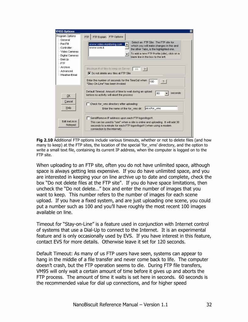
Fig 2.10 Additional FTP options include various timeouts, whether or not to delete files (and how
many to keep) at the FTP sites, the location of the special ‘for_vms’ directory, and the option to
write a small text file, containing its current IP address, when the computer is logged on to the FTP site.
When uploading to an FTP site, often you do not have unlimited space, although space is always getting less expensive. If you do have unlimited space, and you are interested in keeping your on line archive up to date and complete, check the box “Do not delete files at the FTP site". If you do have space limitations, then uncheck the “Do not delete…” box and enter the number of images that you want to keep. This number refers to the number of images for each scene upload. If you have a fixed system, and are just uploading one scene, you could put a number such as 100 and you’ll have roughly the most recent 100 images available on line. Timeout for “Stay-on-Line” is a feature used in conjunction with Internet control of systems that use a Dial-Up to connect to the Internet. It is an experimental feature and is only occasionally used by EVS. If you have interest in this feature, contact EVS for more details. Otherwise leave it set for 120 seconds. Default Timeout: As many of us FTP users have seen, systems can appear to hang in the middle of a file transfer and never come back to life. The computer doesn’t crash, but the FTP operation seems to die. During FTP file transfers, VM95 will only wait a certain amount of time before it gives up and aborts the FTP process. The amount of time it waits is set here in seconds. 60 seconds is the recommended value for dial up connections, and for higher speed

NanoBiscuit Reference Manual – Version 1.1 33
connections, one could lower this value to 30 seconds. Perhaps most useful in the case of really slow, one could up this value to 120 seconds.
The “Check for for_vms directory…” option. The for_vms directory is a special directory located at the FTP site to which you are uploading, and is used as a folder to hold files that you want to send to the VM95 camera station. The “vms” in for_vms stands for “video monitoring station”. And any files placed in this directory are “for” the “vms” station. Please see the section on “Non-Direct Re-Programming of VM95 over the Internet” for more details on how to use this capability. The “Send/Remove IP address...” option is useful in some cases, when you want to know what IP address your cameras station is using for its Internet connections. The current IP address is written in a small text file called “ip.txt” and is put in the “from_vms” directory under the archive directory at the FTP site. This file gets written as soon as an FTP connection is made, and the file is deleted right before the FTP connection is released, so it is essentially an indicator of when your camera system is uploading. Since it also tells you its IP address, this can be used, in conjunction with remote control programs to connect to the camera system. Note that if you do take control of a system in this manner, it is important that you immediately click on the menu choice “Stay On Line”, which will tell the system not to hang up the modem at the end of the uploading operation.
2.3.8 Archive Options

NanoBiscuit Reference Manual – Version 1.1 34
Fig 2.11 The Archive options: The archive directory name is where all your imagery is stored
locally and is also used a the remote site where the images are uploaded.
The Archive Directory is a required field. The 2nd and 3rd Archive directories names are optional. The can be used to mirror the archive of images, or for backup to an external hard drive. Whether or not a sampled image is saved in the 2nd 3rd and 4th archives is determined in the Sample Schedule for each scene, that is, it can be turned on and off depending on the scene. Use Simplified Date/Time Names saves the images at the FTP site differently. Read the ? help buttons on the to the right of the check box for more details. Save to the Argus Standard saves the images locally with names that follow the Argus convention (used in beach and shoreline studies). Since all the files are saved in one directory, you must set the limit for the maximum number of files saved in the argus subfolder. Total Number of Drives was used only in older systems and is not used anymore. Maximum number of files per directory is used to limit the number of files in any one directory. A new subdirectory is created when the limit is reached.
NanoBiscuit Reference Manual – Version 1.1 35
2.3.9 The Advanced Options
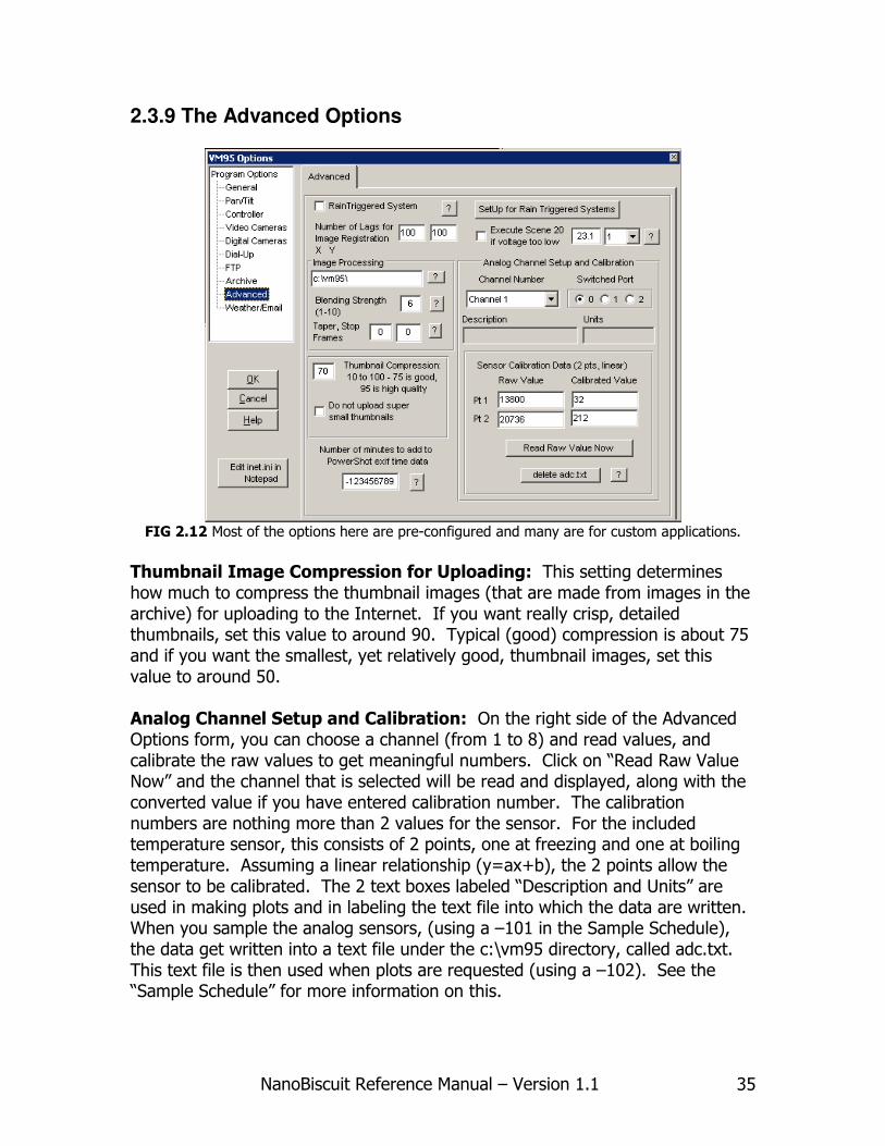
FIG 2.12 Most of the options here are pre-configured and many are for custom applications.
Thumbnail Image Compression for Uploading: This setting determines how much to compress the thumbnail images (that are made from images in the archive) for uploading to the Internet. If you want really crisp, detailed thumbnails, set this value to around 90. Typical (good) compression is about 75 and if you want the smallest, yet relatively good, thumbnail images, set this value to around 50. Analog Channel Setup and Calibration: On the right side of the Advanced Options form, you can choose a channel (from 1 to 8) and read values, and calibrate the raw values to get meaningful numbers. Click on “Read Raw Value Now” and the channel that is selected will be read and displayed, along with the converted value if you have entered calibration number. The calibration numbers are nothing more than 2 values for the sensor. For the included temperature sensor, this consists of 2 points, one at freezing and one at boiling temperature. Assuming a linear relationship (y=ax+b), the 2 points allow the sensor to be calibrated. The 2 text boxes labeled “Description and Units” are used in making plots and in labeling the text file into which the data are written. When you sample the analog sensors, (using a –101 in the Sample Schedule), the data get written into a text file under the c:\vm95 directory, called adc.txt. This text file is then used when plots are requested (using a –102). See the “Sample Schedule” for more information on this.

NanoBiscuit Reference Manual – Version 1.1 36
2.3.10 The Weather/Email Options
Fig 2.13 Weather Options when using the Davis Weather Wizard III or the Davis Monitor II.
Error Reporting and Email Notification: All internet connected Nano-Biscuit systems have, built into VM95, the ability to report system malfunction to the end user. These error messages can be sent via email or text message to multiple users. You must check the corresponding boxes shown in Fig 1.12. The first type of notification is SMS. You can enter multiple phone numbers in the provided text input. You must separate numbers with commas. Numbers must also include the country code. Ex: “13052529560,393484780143” The buttons below will send out test SMS messages to the corresponding numbers. The second type of notification is email. Enter the email addresses in the text input separated by commas. Ex: “[email protected],[email protected]”. The buttons below will send out test email messages to the corresponding addresses. The third type of notification is operational data sent to EVSCenter. This database is monitored by EVS for any possible errors. This type of error reporting is only sent to EVS and not the user. EVSCenter only receives the same type of notices that are sent to the user.
NanoBiscuit Reference Manual – Version 1.1 37
Chapter 3
Software Options and Settings

NanoBiscuit Reference Manual – Version 1.1 38

NanoBiscuit Reference Manual – Version 1.1 39
3.1 Programming the Sample Schedule The Sample Schedule is where most of the programming is done once the system has been initially setup. As mentioned earlier, a metaphor for the sampling schedule is “Scenes”. Each “Scene” has a daily On and Off time and an Interval (the Internal determines at what interval during the “On” time that the scene gets sampled). Sampling a “scene” involves executing what the scene is setup to do. There are about 11 different operations a “scene” can do; they are: 0 Video Image Capture -98 Digital Image Capture -99 AutoPan Image Capture -998 Composite upload to the Internet –997 Single Scene upload to the Internet –101 Sample the analog channel –102 Make plots of the weather or analog data –995 Timelapse sequence upload to the Internet -96 Capture motion video direct to a file –994 Make an Mpeg movie and/or make and save composite images –999 Reboot the system
The number in bold is simply an abbreviation for the scene. It is used as a shorthand method to refer to a scene’s operation. A note about Composite images: One of the unusual strengths of VM95 is the way it can handle composite images. A composite image is any collection of images, from 1 to more than 9 images, that is defined in the “Composite Image layout”. For example, when using a pan/tilt unit, you may want to do a panorama consisting of 5 images from left to right. You could use a –99 (autopan image capture) to acquire the images and store them in the archive locally. You would define a 5 column, single row composite in the “Composite Image Layout” that would point to the 5 scenes captured with the –99. Then in order to upload these to the Internet, you would use a –998, in which you would simply reference the composite layout you defined, and all the details of gathering the files, making thumbnails, naming them, laying them out on the web page, etc would be taken care of automatically. Archiving: Images are archived to the local hard disk whenever they are sampled. That is, when you do an image capture via a “–98”, “-99” or a “0” operation, the captured image is archived in a specific directory structure. An example will illustrate this: Use “pics” for the archive directory and set up Scene 1 to be a –98, a Digital Camera Capture. The very first time you sample this image in automatic mode, (or if you do Menu->Test->Test Capture, Label and

NanoBiscuit Reference Manual – Version 1.1 40
Archive”), a series of subdirectories will be created under c:\pics. If today’s date is March 21 2009, then the image acquired will be saved as c:\pics\s1\mar2109k\m211130a.jpg The various subdirectories have the shown name because: c:\pics this is the archive directory name you set in Options s1 this is used because the sample was setup in Scene 1 (of the Sample Schedule); mar2109k mar21 stands for March 21; 01 stands for year 2001, and the k at the end represents the hour of the day that this directory was created (a-w represent hour 0 – 23 respectively) m211130a.jpg this is the file name for the captured image; m21 stands for March 21, 1130 stands for 11:30 in the morning, and the “a” represents the “seconds” of the time the image was captured. The letters a-z represent the number of seconds from 0 to 59. The letter used for the month is:
j January f February m March a April y May u June l Jul g August s September o October n November d December
The use of the intermediate sub directory called mar2101k in the above example is needed in order to keep the number of files in any one directory from getting too large and unmanageable. The date encoded into this subdirectory corresponds to the first file written into the subdirectory. When the total number of images exceeds 1600 images, the archiving operation automatically creates a new subdirectory, using the date/time from the image to be saved. New sub-directories are created every 1600 images, and/or every 3 months starting with January, which ever comes first. “s” scenes are used for standard capture scenes “p” scenes are used for auto pan scenes “d” scenes are used for post processed scenes such as making a panorama, resizing, etc “v” scenes are for saved time lapse movies in .wmv format.

NanoBiscuit Reference Manual – Version 1.1 41
“f” scenes are for saved variance images (using video or ueye cameras). “x” scenes are for saved pixel extraction/time stack images in .bmp format.
3.1.1 The -98 Scene 3.1.1.1 An Overview and the General Tab
Fig 3.1 An example screen of what you see when you first enter the Sample Schedule. Here
we see the General tab of a –98 operation
On the left side, in the white list box with the vertical scroll bar, is a listing of the 80 “scenes” that can be programmed, S1 – S80. The Scenes with a green dot next to them are the scenes that are currently active, indicated by the fact that they have a non-zero Sample Interval. To deactivate a scene, so it won’t get sampled, you must set the Sample Interval to 0. A Sample Schedule with no green dots will not do anything when it is put into automatic mode. It will simply flash a message on the Status Line that there are no scenes to sample. To the right of each scene number is a number in parentheses, which is the code for the scene operation, allowing you to quickly recognize where the different scene operations are situated.

NanoBiscuit Reference Manual – Version 1.1 42
Buttons along the Bottom:
Save/Return: saves all changes you made. Cancel/Return: does not save any of the changes you made Table View: saves your changes and presents all the data in a spreadsheet like structure which can be very useful in making global changes, and reorganizing the scene order. Save Schedule: This lets you save all the scene parameters in a text file of your naming, with the extension .sch. It is useful for saving complete setups, and then reloading them at a latter time. We also provide some pre-written sample schedule that you can load and see how certain things are accomplished. Load Schedule: This is for reloading a pre-written or previously saved sample schedule. Wizard: Walks you thru some basic setup scenarios and pre loads some of the fields for you after you’ve selected a number of options.
Fig 3.2 The drop down list for the “Operation to be performed”
At the center top of Fig 3.1 and 3.2, you see “Scene Number 1”, corresponding to S1 at the left in the white list box. Right below this is the “Operation to be performed”, which you can choose using the drop down list box. Different operations will have a different number of tabs. In Fig 3.1, you see the operation is a –98, which is a Digital Camera Acquisition operation. There are four tabs that need to be set up, or at least checked, for proper operation. The tab we see in Fig 3.1 is the “General” tab. This tab is very similar for all the operations since all operations will have an “On” time, “Off” time and an “Interval”. Interval, On and Off: The “On” and “Off” time should always be in the 24 hour format and should always consist of 4 digits with a colon (:) in the middle,
NanoBiscuit Reference Manual – Version 1.1 43
such as 17:35 or 06:45. You can type in the time value without the colon and it will be automatically formatted with the colon for you. The “Interval” is in minutes and represents the amount of time before the operation is repeated, assuming that the time is in the “On” period. Scenes that should be sampled every 20 minutes between 8 in the morning and 5 in the afternoon are easy to set up: Interval=20 On time=08:00 Off time=17:00 What about samples that should start late at night and turn off in the morning? Lets say you want to take pictures of a parking lot from 9 pm to 6 am every 5 minutes. Set up the parameters as follows: Interval=5 On time=21:00 Off time=06:00 The program logic is such that, when it sees an “Off” time that is less than the “On” time, it will assume you are sampling through the night and into the next day. If you want to sample continuously, set the “On” time to “00:00” and the “Off” time to “24:00”. An Interval more than 1 day (1440 minutes) is acceptable, but it is probably more reasonable just to disable certain days. On the Minute: This is a feature that can be quite useful, but can be a bit confusing at first. To understand why it’s needed, you need to understand how the program determines which scene to sample next. Suppose you have programmed up 5 scenes to take pictures and upload images every 20 minutes. Let’s say you start them all at 7:30 am and turn them off at 17:30. When automatic mode starts up, it scans through the list of scenes and computes the next sample time for each scene. In our example, all 5 scenes would be set to sample immediately, assuming it’s after 7:30 and before 17:30. So it “samples” them in the order that they are in, since they have the same first sample time. When it finishes sampling a scene, it computes the next sample time for that scene by adding the interval to its current time. It does not add 20 minutes to the scheduled time, but rather to the current time when it sample the scene. In this way, the scenes will get naturally staggered out in time. Some operations you just don’t know how long they will take, like uploads to the internet, so this strategy ends up working quite well. In certain cases, though, you may want the samples to occur at a very specific time, like at the top of each hour. For example, say you want to capture an image at 8:00, 9:00 … until 17:00. You could set it up as follows: On time = 8:00
NanoBiscuit Reference Manual – Version 1.1 44
Off time = 17:15 Interval= 60 On the minute=checked Tolerance=10 minutes The time 17:15 was used so it will sample at 17:00, otherwise it might start at a second past 17:00 and decide it’s outside the desired sampling on/off times. With “On the Minute” checked, only samples at the top of the hour will be taken. The tolerance is a needed parameter that tells the software how many minutes it can be late and still be required to take the sample. For example, if you start up the automatic mode at 11:05, you will not get your first sample, unless the tolerance is 5 minutes or greater. Or similarly, if another operation takes so long that its already 12:07 before it finishes, a sample with the tolerance set for 10 minutes will still take place, since 12:07 is within 7 minutes of the actually scheduled time. Do not set the tolerance to be greater than the Interval. Since the “On the Minute” scenes take precedence over the regular scenes (which do not have “On the Minute” checked), you could get stuck sampling only one scene the whole time if your tolerance is larger than the Interval. As a general rule, we recommend making the tolerance about ¼ or less than the Interval, If you are not sure whether you need “On the Minute”, it’s best to leave it unchecked. Day of the Week: These check boxes left you turn on and off the sampling for various days of the week. If none of them are checked, the scene will never be sampled.
Up to this point, the comments made regarding Fig 3.1 are the same for all scenes. They all have on, off, interval and on the minute parameters. The following comments are specific to the type of scene we are sampling. Fig 3.1 is a –98, that is, a Digital Camera Acquisition scene. On the General tab you see a zoom setting, this can be set for 0 (wide angle) to 13 (zoomed all the way). Also on this General tab is a check box called “Repetitive DC120 Shots to CompactDisk.” This option is for a specific client only. Leave this box unchecked. Finally, on this General tab is the check box labeled “Save Image under a different scene Number”. This can be extremely useful in certain cases, especially when you need to program many scenes to accomplish the sampling of a certain process in the manner you want. For example, let’s say you just want to take shots during rush hour traffic, from 7:00 – 9:00 am and from 15:00 – 18:00 daily. You can easily program up two scenes to do this. But if you want to make a slideshow showing both sets of images in the same slideshow, you’d
NanoBiscuit Reference Manual – Version 1.1 45
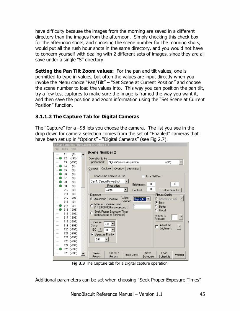
have difficulty because the images from the morning are saved in a different directory than the images from the afternoon. Simply checking this check box for the afternoon shots, and choosing the scene number for the morning shots, would put all the rush hour shots in the same directory, and you would not have to concern yourself with dealing with 2 different sets of images, since they are all save under a single “S” directory. Setting the Pan Tilt Zoom values: For the pan and tilt values, one is permitted to type in values, but often the values are input directly when you invoke the Menu choice “Pan/Tilt” – “Set Scene at Current Position” and choose the scene number to load the values into. This way you can position the pan tilt, try a few test captures to make sure the image is framed the way you want it, and then save the position and zoom information using the “Set Scene at Current Position” function. 3.1.1.2 The Capture Tab for Digital Cameras The “Capture” for a –98 lets you choose the camera. The list you see in the drop down for camera selection comes from the set of “Enabled” cameras that have been set up in “Options” - “Digital Cameras” (see Fig 2.7).
Fig 3.3 The Capture tab for a Digital capture operation.
Additional parameters can be set when choosing “Seek Proper Exposure Times”

NanoBiscuit Reference Manual – Version 1.1 46
Fig 3.4 Seek exposure parameters
VM95 incorporates a simple algorithm to seek an exposure setting that allows you to achieve a certain exposure often not possible with automatic settings. This desired “Average Brightness” parameter can be set. Completely black is 0 and all white is 255. A good night time value is around 90 to 120, depending what’s of interest. The Region of Interest should be set to all 0’s. In this way, the whole image will be used when computing the average brightness of the image. To use the ‘Region of Interest’, you must enter normalized values (from 0-80 for x and 0-60 for y) for the coordinates and width and height. Double-Click on the gray box in the upper right and the latest image snapped with ‘Test Capture and Label’ will be loaded into the window. Simply draw a box with the mouse clicked down, and when you release the mouse, the 4 values will be loaded correctly into the text boxes. The algorithm referred to above involves taking a picture, using the exposure time specified in the “starting exposure”. This is in usec (micro seconds, or millionths of a second). Put a value like 100000 (0.1 seconds) for a starting value. After the image gets taken, the algorithm computes the image’s average brightness, and, if the brightness is more than 15 units away from the Average Brightness parameter, the program estimates a new exposure time, and re-shoots the image, and will loop for up to 10 times until it gets to the “best” exposure it can. Maximum exposure time is 16 seconds. When the algorithm finishes, the exposure time used is placed as the “starting exposure” parameter, so that when the scene is sampled again, it will start from the “best” exposure time it had most recently. A White Balance of “Daylight” is usually the best setting for daytime shots, whereas for night time shots, “Tungsten” gives nice results. Picture Quality: This determines the quality of the image that the camera sends to the computer. We usually set this to “Best”. (Uncompressed is not yet supported, so don’t choose it). Be aware that it is this image that gets resized,
NanoBiscuit Reference Manual – Version 1.1 47
adjusted, and labeled and it is then re-saved as a Jpeg image (for the second time) in the archive directory. There is a separate setting for the quality of this 2nd “saving” and that is set under the “Archive” tab. Adjust the Brightness to an exact value after its Captured: This setting adjusts the brightness of the whole image, after it has been captured, to within a few counts of the value you set. It can be very useful in making a visually smooth looking time lapse sequence out of an image set that normally might bounce around in brightness, such as when clouds go by. All black images will become all gray images, and look strange for night time shots. This feature seems more useful for day time shots because of this. 3.1.1.3 The Overlay Tab
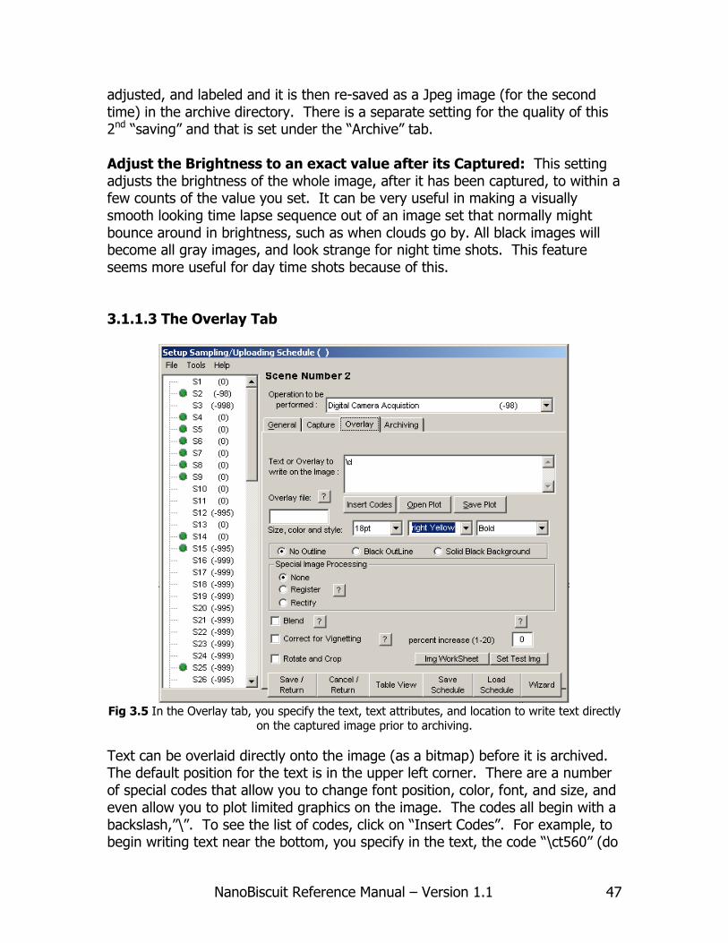
Fig 3.5 In the Overlay tab, you specify the text, text attributes, and location to write text directly
on the captured image prior to archiving.
Text can be overlaid directly onto the image (as a bitmap) before it is archived. The default position for the text is in the upper left corner. There are a number of special codes that allow you to change font position, color, font, and size, and even allow you to plot limited graphics on the image. The codes all begin with a backslash,”\”. To see the list of codes, click on “Insert Codes”. For example, to begin writing text near the bottom, you specify in the text, the code “\ct560” (do
NanoBiscuit Reference Manual – Version 1.1 48
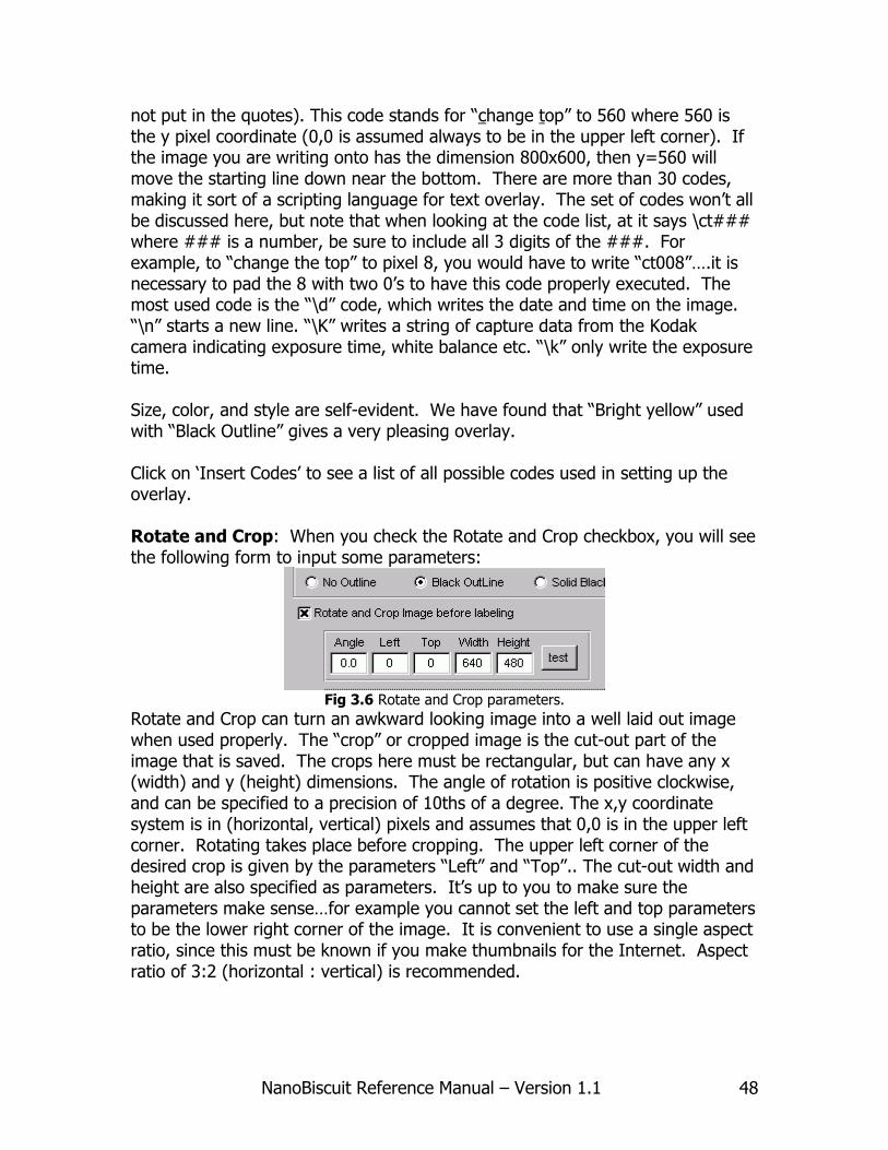
not put in the quotes). This code stands for “change top” to 560 where 560 is the y pixel coordinate (0,0 is assumed always to be in the upper left corner). If the image you are writing onto has the dimension 800x600, then y=560 will move the starting line down near the bottom. There are more than 30 codes, making it sort of a scripting language for text overlay. The set of codes won’t all be discussed here, but note that when looking at the code list, at it says \ct### where ### is a number, be sure to include all 3 digits of the ###. For example, to “change the top” to pixel 8, you would have to write “ct008”….it is necessary to pad the 8 with two 0’s to have this code properly executed. The most used code is the “\d” code, which writes the date and time on the image. “\n” starts a new line. “\K” writes a string of capture data from the Kodak camera indicating exposure time, white balance etc. “\k” only write the exposure time. Size, color, and style are self-evident. We have found that “Bright yellow” used with “Black Outline” gives a very pleasing overlay. Click on ‘Insert Codes’ to see a list of all possible codes used in setting up the overlay. Rotate and Crop: When you check the Rotate and Crop checkbox, you will see the following form to input some parameters:
Fig 3.6 Rotate and Crop parameters.
Rotate and Crop can turn an awkward looking image into a well laid out image when used properly. The “crop” or cropped image is the cut-out part of the image that is saved. The crops here must be rectangular, but can have any x (width) and y (height) dimensions. The angle of rotation is positive clockwise, and can be specified to a precision of 10ths of a degree. The x,y coordinate system is in (horizontal, vertical) pixels and assumes that 0,0 is in the upper left corner. Rotating takes place before cropping. The upper left corner of the desired crop is given by the parameters “Left” and “Top”.. The cut-out width and height are also specified as parameters. It’s up to you to make sure the parameters make sense…for example you cannot set the left and top parameters to be the lower right corner of the image. It is convenient to use a single aspect ratio, since this must be known if you make thumbnails for the Internet. Aspect ratio of 3:2 (horizontal : vertical) is recommended.

NanoBiscuit Reference Manual – Version 1.1 49
3.1.1.4 The Archive Tab
Fig 3.7 The Archiving tab lets you control the quality of the saved image, how much local disk
space to set use for the scene and more.
All images that are captured get archived. You can set a size limit on how much space you want the scene to occupy on the local hard disk. Once the size of all the images in the scene exceeds the number of Megabytes you specify, the oldest images will get deleted to maintain to total space usage under the limit you set. Images on the 2nd, 3rd, and 4th archive never get deleted. Managing their disk space is up to you. The Jpeg quality when we save the image (after resizing and labeling the captured image) can be set from 0-100. Setting it to 0 is interpreted as setting it to the default value which is 75 in this case. “100” results in a near perfect image whose size is about ½ the size of the equivalent 24 bit color, bitmap image. A value is 75 gives you a compression of around 10-20, and has only a slight visual artifacts that become more and more evident as you zoom in on the image. A value a 50 will result in a very small file size, but artifacts of the compression (blocky and patchy looking, with distinct horizontal and vertical lines with lengths in multiples of 8 pixels) will be apparent. Save to 2nd, 3rd and 4th archives: In the “Options” “Archive” setting, you can specify a 2nd, 3rd and 4th archive, which can be any device that Windows can

NanoBiscuit Reference Manual – Version 1.1 50
write to, and for which it has a drive letter. If one or all are specified, and you have checked this box, then, besides saving the image in the main archive, it will get saved identically in the 2nd 3rd and 4th archive. In addition, save image to a specified file name: Sometimes it is convenient to have the latest image captured saved somewhere with a fixed filename, which gets overwritten each time the image is sampled and archived. You can specify the drive letter, path and filename, or if you just specify the filename, it will save the file in the directory from where VM95 is running (usually c:\vm95)
3.1.2 Setting Up an AutoPan Scene:
Fig 3.8 The AutoPan (-99) General Tab
The AutoPan operation is a one scene method to take many images; each successive image shifted and tilted a fixed amount relative to the previous image. This allows one to efficiently setup a panorama sweep, for example, of an
area up to 360°.
In the AutoPan General Tab shown above, note that relative to General tab of a –98 (Digital Cam Capture), the pan tilt values near the zoom values have disappear and a new set of parameters appeared near the bottom.

NanoBiscuit Reference Manual – Version 1.1 51
Put all images into one “S” directory: Leave this checked box unchecked for now; when this is checked, it changes how the images are archived. Total number of scenes: The total number of images to be taken during the complete autopan operation is given by this value. You set this. If you want a 4 scene panorama, set this to 4. Archiving of the scenes will go into the “p” archives. Normal capture scenes (-98 and 0) archive their images in the “s” archives as discussed already. AutoPan scenes go into the “p” series, and you need to tell it which number to begin with, which you set in the Starting Scene Number parameter. The Ending scene number is a computed field that shows you that last scene number to be used just for your information. It cannot be set. So typically you might choose 4 for the “Total number of scene” and let’s say 10 for the “Starting scene number”. When the sampled in automatic mode, you will get 4 images making up the panorama, saved into the p10, p11, p12 and p13 directories. Unfortunately you cannot “Test Capture and Label” an autopan scene. The first scene will be taken with the pan tilt unit at the values set by the Starting pan value, and the Starting tilt value. The second image will be shifted to the right by the amount given in pan shift and tilted down by the amount given in tilt shift. If the values are negative, the pan will shift left and the tilt will shift up. It turns out to be convenient if you choose the far left scene as the starting position, and use positive values for the shift. Often in a panorama, the tilt remains 0, but sometimes, due to an imperfect horizontal mounting job, as the unit pans, it drifts up or down, making steps in the images where they should join. You can use the tilt shift to correct for this. Trial and error is the best way to remove this “step” problem; typical correction values range from +/-8 to +/- 40. With the AutoPan images saved in their respective “p” directories, one can define composite images that can be used to create a single, large panorama image (-994). Use Digital camera AutoPan: Make sure this box is check if you’re using Digital cameras. AutoPan was originally developed assuming one was using a video camera. With the availability of digital cameras, this checkbox was created to do the same autopan for the digital cameras.

NanoBiscuit Reference Manual – Version 1.1 52
3.1.2.1 Capture Tab for an AutoPan using a Digital Camera
Fig 3.9 The Capture Tab for an AutoPan (-99) when using a Digital cam.
Fig 3.9 shows the Capture tab for an AutoPan using a Digital camera. It is essentially a pointer to a –98 scene where the capture tab has been setup with all the desired parameters. The drop down list shows you all the scenes that are of the type –98, since only these scenes will have a properly configured Capture Tab. You must make sure the scene is setup properly, and it would be advisable to do a “Test Capture and Label” on the scene to test it out.
3.1.3 Uploading to the Internet It is assumed that you have configured access to the Internet, and access to the FTP sites in the Options form. If you haven’t, go to the Options form in Section 1.0 There are 3 scene operations that do Internet upload: -997 single file upload -998 composite upload -995 time lapse sequence upload All three of these operations share the same “General” Tab:

NanoBiscuit Reference Manual – Version 1.1 53
Fig 3.10 The General tab that is the same for all Upload operations.
There is only one new field we’ve haven’t seen here. It is the checkbox labeled “Do Not Call ISP for Uploading, use the local LAN. This was needed to support older dial up connections and is no longer used. Also in common for all three types of uploads, is the MultiFile tab:

NanoBiscuit Reference Manual – Version 1.1 54
Fig 3.11 The Multi-file options allow you to send a list of files from the local machine to an FTP
site.
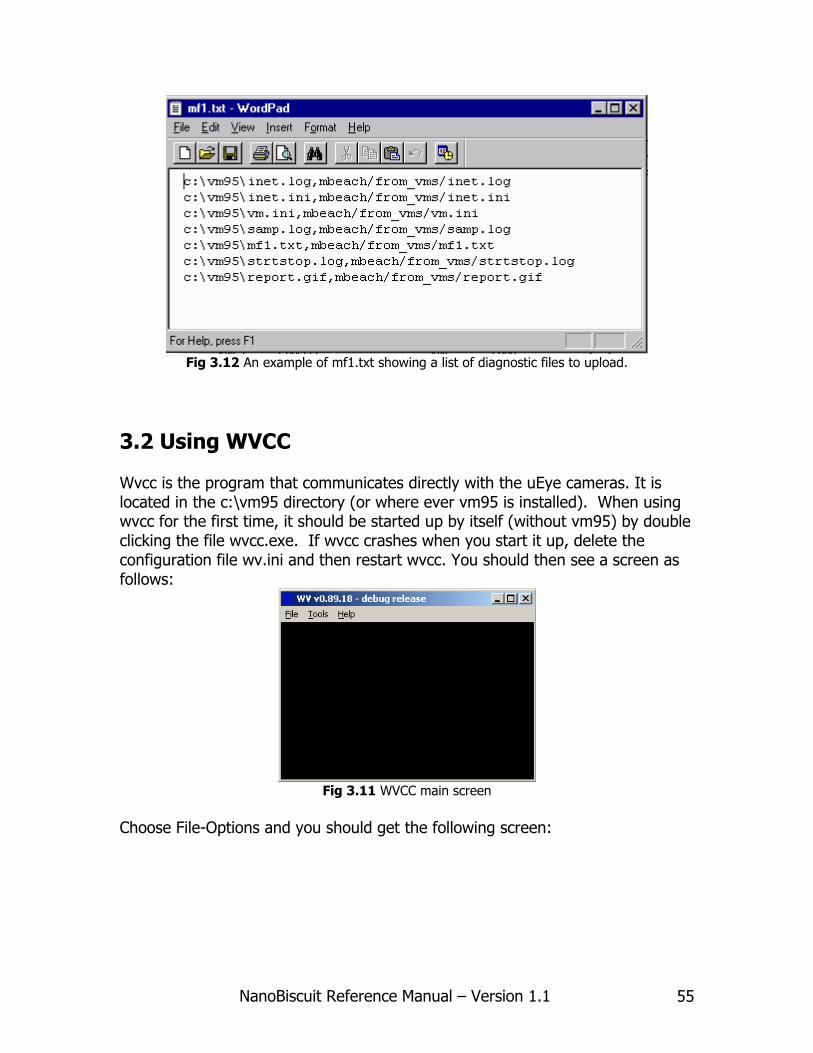
MultiFile operations were created to address the need of sending a list of existing files from the local computer to the FTP site, allowing you to set the path and filename at the destination site. We use this principally for sending our diagnostic files to the Internet so they can be accessed and checked without disturbing the camera system. A number of our clients use this to send data files from one location to another on their LAN at a regular schedule. There are 4 ascii files that can be viewed and edited with any text editor (notepad or write). Any of the 3 upload operations can be requested to send one of these 4 files at the end of its upload operation. The 4 ascii files are found in the application directory (usually c:\vm95) and are called mf1.txt, mf2.txt, mft3.txt and mf4.txt. Fig 2.12 shows and example of mf1.txt loaded with the usual set of diagnostic files we like to upload. Each line consist of 2 complete path and filenames separated by a comma ( , ). The first path file name is the local file on the Biscuit WinXP computer, and the second file name is for the destination at the FTP site, relative to its starting directory. Note that use of backslash for the local file and normal slash for the Internet file.
NanoBiscuit Reference Manual – Version 1.1 55
Fig 3.12 An example of mf1.txt showing a list of diagnostic files to upload.
3.2 Using WVCC Wvcc is the program that communicates directly with the uEye cameras. It is located in the c:\vm95 directory (or where ever vm95 is installed). When using wvcc for the first time, it should be started up by itself (without vm95) by double clicking the file wvcc.exe. If wvcc crashes when you start it up, delete the configuration file wv.ini and then restart wvcc. You should then see a screen as follows:
Fig 3.11 WVCC main screen
Choose File-Options and you should get the following screen:

NanoBiscuit Reference Manual – Version 1.1 56
Fig 3.12
Check “Show system messages…” so you can see the progress when wvcc starts up. Click on Network on the left side panel; you should see this:
Fig 3.13
The port number and the Silverlight Access check box are for remote viewing and control of the camera. Contact EVS if you want to use these features. The Video Selection shows you this:
NanoBiscuit Reference Manual – Version 1.1 57
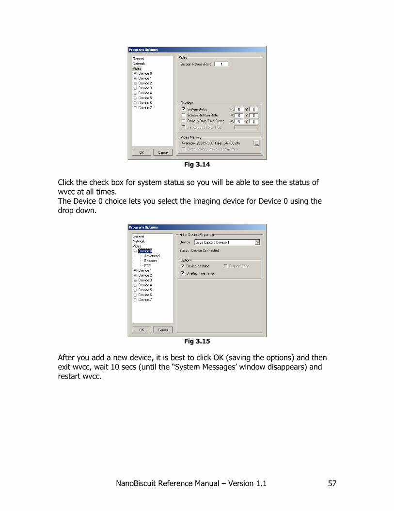
Fig 3.14
Click the check box for system status so you will be able to see the status of wvcc at all times. The Device 0 choice lets you select the imaging device for Device 0 using the drop down.
Fig 3.15
After you add a new device, it is best to click OK (saving the options) and then exit wvcc, wait 10 secs (until the “System Messages’ window disappears) and restart wvcc.

NanoBiscuit Reference Manual – Version 1.1 58
Fig 3.16
In the ‘Advanced’ properties, you can access the Capture Filter and Capture Pin. These are options and settings that the uEye driver lets you access. Proper operation depends on some of these settings, in particular, the Pixel Clock settings in the Capture Pin shown below.
Fig 3.17
For 1.6GHz Atom processors, you should not go above 7Hz for one camera and 5MHz for multiple cameras. You want to avoid dropped frames, which you can verify under the Device tab of the Capture Filter properties:
NanoBiscuit Reference Manual – Version 1.1 59
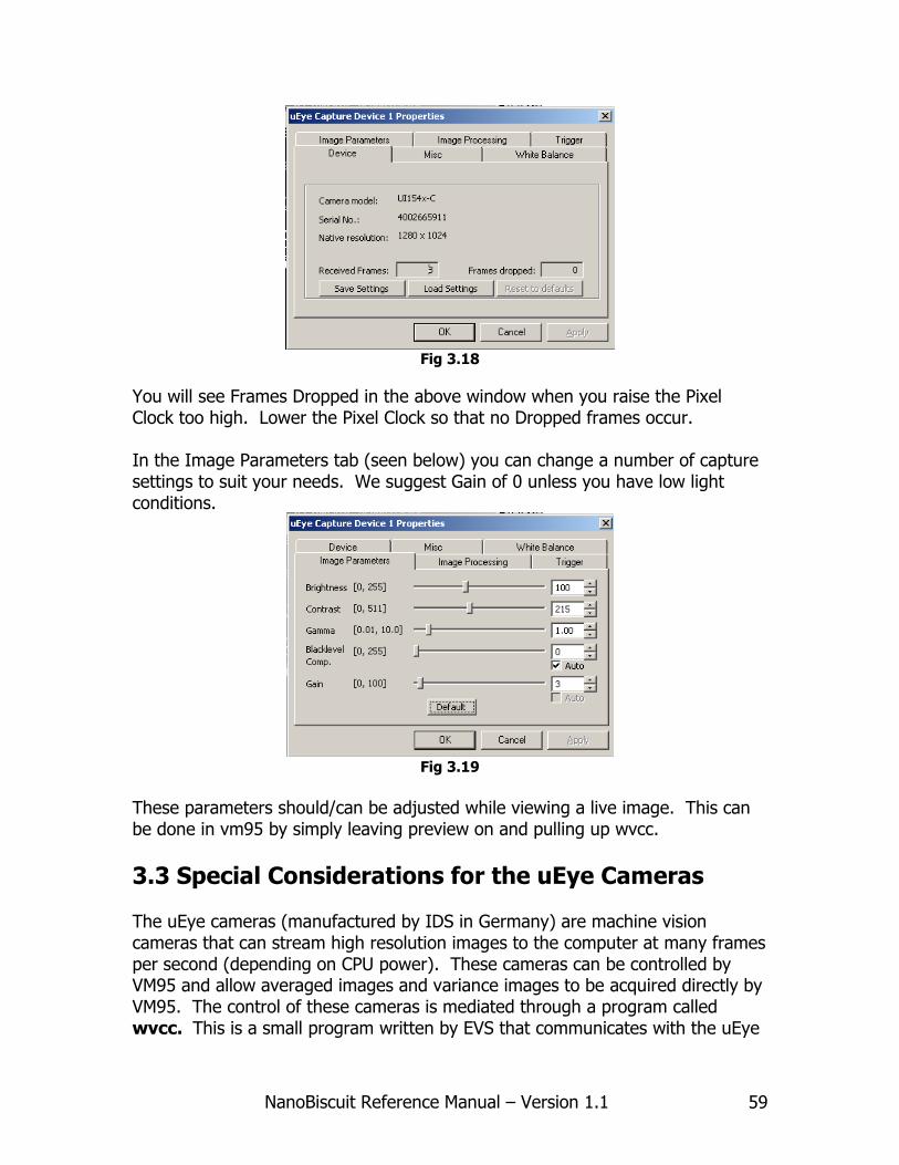
Fig 3.18
You will see Frames Dropped in the above window when you raise the Pixel Clock too high. Lower the Pixel Clock so that no Dropped frames occur. In the Image Parameters tab (seen below) you can change a number of capture settings to suit your needs. We suggest Gain of 0 unless you have low light conditions.
Fig 3.19
These parameters should/can be adjusted while viewing a live image. This can be done in vm95 by simply leaving preview on and pulling up wvcc.
3.3 Special Considerations for the uEye Cameras The uEye cameras (manufactured by IDS in Germany) are machine vision cameras that can stream high resolution images to the computer at many frames per second (depending on CPU power). These cameras can be controlled by VM95 and allow averaged images and variance images to be acquired directly by VM95. The control of these cameras is mediated through a program called wvcc. This is a small program written by EVS that communicates with the uEye
NanoBiscuit Reference Manual – Version 1.1 60
cameras through a DirectX/DirectShow interface. There are a number of settings that must be correctly configured for these cameras to work. First, the uEye software must be installed, and when the cameras are plugged into the USB, the red LED on the back of the camera should turn green. This indicates that Windows is communicating with the cameras. When using more than one camera, you must insure that they have unique ID’s. There are a number of utility and demo programs that come with the uEye software. The program “uEye Camera Manager” allows you to set the device ID of the camera. The program “DirectShow device manager” lets you add and remove cameras from DirectShow management and registers the ones you have chosen. These programs are simple and easy to use; more details on how to use these programs can be found in the uEye help files.
3.4 Common Re-Programming Tasks 1 - Change ftp site and login information 2 – Turn off a scene 3 – Add a scene 4 – Change the On/Off times and Interval for a scene 5 – Figure out which scene is taking an image seen on a web page 6 – Backup options and strategies 7 – Check out and adjust available disk space Section in progress…

NanoBiscuit Reference Manual – Version 1.1 61
Notes

NanoBiscuit Reference Manual – Version 1.1 62
NanoBiscuit Reference Manual – Version 1.1 © Erdman Video Systems, Inc. 2010
8895 SW 129th Street, Miami, FL 33176 Tel: 305.252.9560 | Fax: 305.969.9280