nano tube based sensors for capnography
TRANSCRIPT
NANOTUBE BASED SENSORS FOR CAPNOGRAPHY
By
Ushaswini Chowdary.M
Capnography
• Capnography is the monitoring of the concentration or partial pressure of
carbondioxide(CO2) in the respiratory gases. Its main development has
been as a monitoring tool for use during anesthesia and intensive care .
• It is usually presented as a graph of expiratory CO2 (measured in
millimeters of mercury, "mmHg") plotted against time, or, less commonly,
but more usefully, expired volume.
• The capnogram is a direct monitor of the inhaled and exhaled
concentration or partial pressure of CO2, and an indirect monitor of
the CO2 partial pressure in the arterial blood.
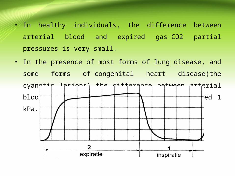
• In healthy individuals, the difference between arterial blood and expired
gas CO2 partial pressures is very small.
• In the presence of most forms of lung disease, and some forms
of congenital heart disease(the cyanotic lesions) the difference between
arterial blood and expired gas increases and can exceed 1 kPa.
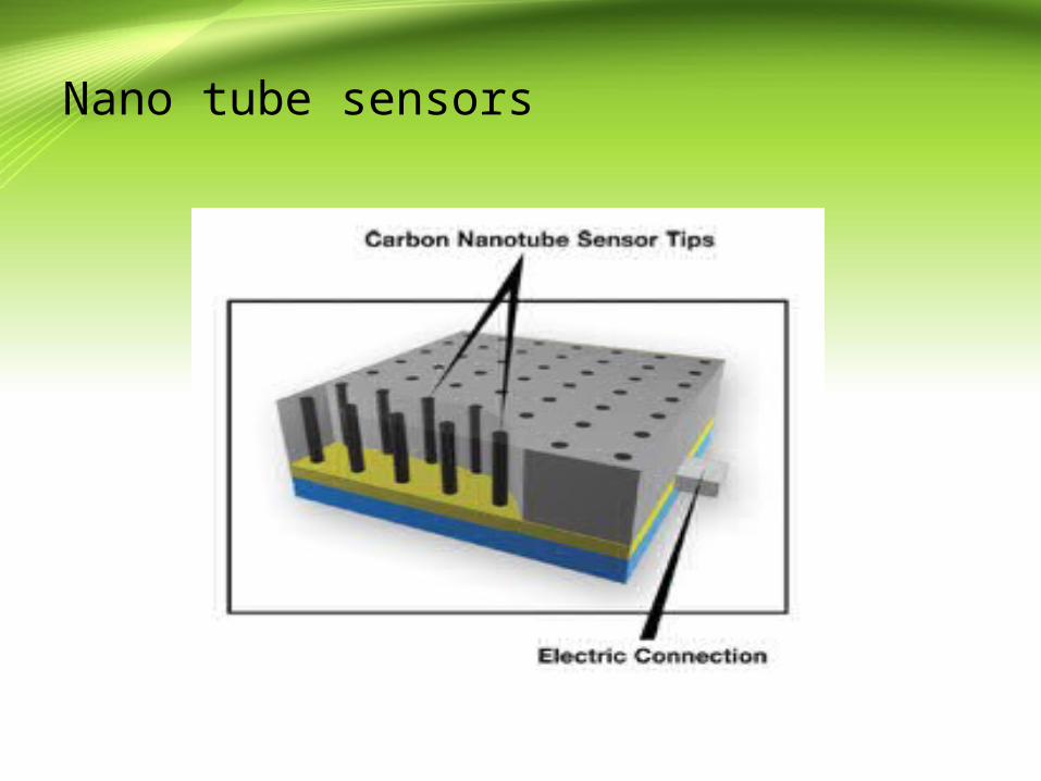
Nano tube sensors
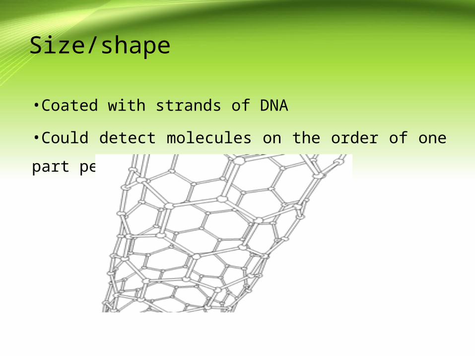
Size/shape
•Coated with strands of DNA
•Could detect molecules on the order of one part per million
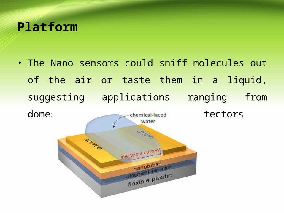
Platform
• The Nano sensors could sniff molecules out of the air or taste
them in a liquid, suggesting applications ranging from
domestic security to medical detectors

APPLICATIONS
FOR BLOOD GLUCOSE MONITARING
•Enzyme glucose oxidase is non-covalently attached
•Brings catalysation of glucose yielding hydrogen-peroxide
•Enzyme immobilisation allows flow of current

Types of sensors for detection
• For development of such a sensor is shown by use of
functionalized carbon nanotube (CNT) materials.
• Single-walled carbon nanotubes (SWNTs) functionalized with
polyethylene imine (PEI) is used as the CO2 sensitive
material.
• A conductivity measurement technique using surface acoustic
wave (SAW) sensors enables measurement of SWNT
conductivity with very high resolution
CURRENT CAPNOGRAPHY SENSORS
• Respiratory carbon dioxide (CO2) gas analysis or
capnography, has become a critical part of a number of
diagnostic tests and monitoring devices used clinically.
• After anesthesia, respiration can be depressed because of
anesthesetic agents or additionally administered drugs (namely
opioids) used to control pain leading to a rise in CO2
concentration (hypercapnia).
• Integration of respiratory gas analysis with measures of breathing pattern
(e.g., tidal volume, respiratory rate) and ventilation to obtain measures of
oxygen consumption(VO2) and carbon dioxide production (VCO2), can
provide powerful prognostic information in a number of diseases.
• In the case of hypercapnia (excess CO2 in blood), breath analysis requires
measurement of concentration of CO2.
• Current measurement systems for CO2 gas analysis include infra-red
analyzers andmass spectrometers.
• Bedside infra-red analyzers are used for respiratory CO2 gas analysis in
anesthesiology

• Mass spectrometers have always been considered the gold standard for
respiratory gas analysis for a number of reasons, including fast response
time, ability to measure dry gases, accuracy and stability of measures.
• In addition they have the advantage of measuring multiple gases
simultaneously.
• Several modifications can be made to mass spectrometers to further reduce
gas delays and enhance response times.
• A major limitation of both bedside infrared analyzers and mass
spectrometers is the fact that they are expensive, bulky, cannot be used for
ambulatory applications and for remote dynamic applications

• Thus there is a need for new technology that would overcome
many of these current obstacles.
• More recently developed infrared probe (PhaseIn Medical
Technologies, Inc.) may be used to measure CO2 at the nose
of the patient.

SOLID-STATE TECHNOLOGIES FOR CO2 SENSING
• Solid-state CO2 sensors developed using responsive materials have the
potential to be small, inexpensive and directly mountable beneath the nasal
cavity, making them attractive for ambulatory monitoring.
• Materials found responsive include polymers , carbon nanotubes and
metal carbonates.
• However, most sensors have been reported to be unacceptably sensitive to
other respiratory variables (like temperature, humidity and other gases),
making them inadequate for respiratory CO2 analysis

Carbon nanotube coated surface acoustic wave• carbon nanotube (CNT) coated surface acoustic wave (SAW) sensors are
investigated for CO2 sensing.
• principle of resonant-frequency measurement of surface acoustic
wave(SAW) devices, for observing extremely small changes in mass
during gas chromatography.
• SAW devices can be operated in a batteryless wireless fashion for a variety
of sensing applications. Combined with their small size, low-cost and ease
of manufacturing, SAW devices become attractive candidates for sensitive,
portable gas sensing.

• SAW devices have a piezoelectric substrate excited by comb-like metal
patterns called inter-digital transducers(IDTs
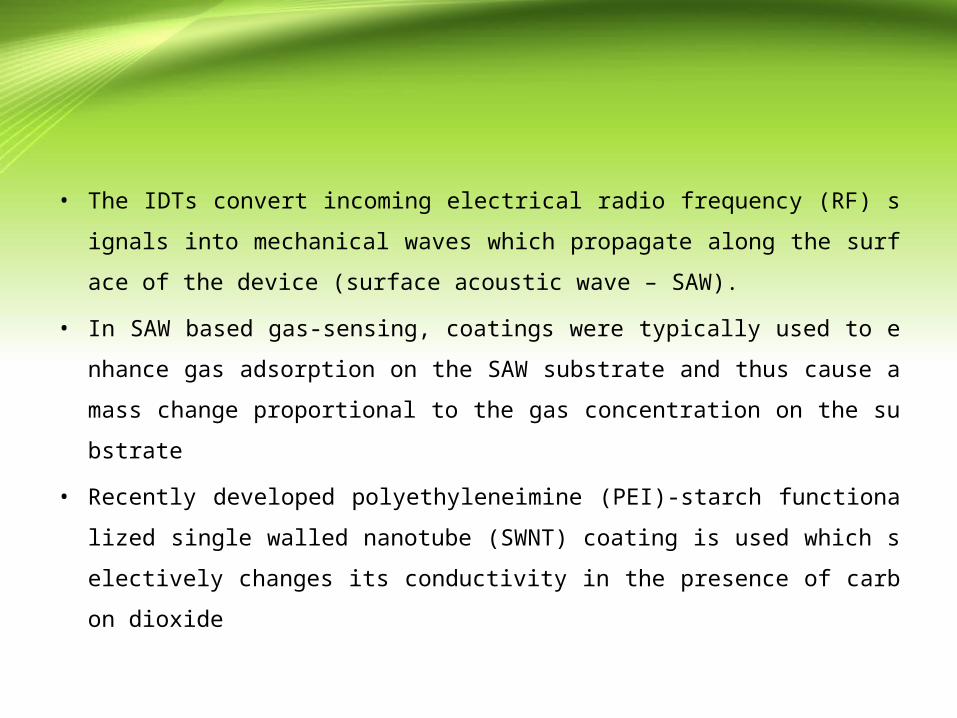
• The IDTs convert incoming electrical radio frequency (RF) signals into me
chanical waves which propagate along the surface of the device (surface ac
oustic wave – SAW).
• In SAW based gas-sensing, coatings were typically used to enhance gas ad
sorption on the SAW substrate and thus cause a mass change proportional t
o the gas concentration on the substrate
• Recently developed polyethyleneimine (PEI)-starch functionalized single
walled nanotube (SWNT) coating is used which selectively changes its con
ductivity in the presence of carbon dioxide
04/15/23
CARBON NANOTUBES AS GAS SENSING MATERIALS
• The conductivity of carbon nanotubes (CNT) films is sensitive to a variety
of gases .
• Such conductivity-sensitive CNT films are thus attractive coatings for SA
W devices.
• CO2 being a weakly reducing gas does not affect CNT film conductivity a
ppreciably
• Multiwall nanotube (MWNT)- silicon dioxide composite films changed the
ir permittivity and conductivity upon exposure to CO2.

04/15/23
• It was recently reported that conductivity of PEI-starch functionalized singl
e walled carbon nanotubes (SWNTs) was sensitive to the concentration of
CO2 .
• Earlier work , the change in CO2 concentration was measured as a change i
n current of a MOSFET with the CNT film acting as its semiconducting lay
er.
• However, it has been reported that the repeatability of such CNT-FETs is af
fected by oxygen adsorption at the metal-CNT film junctions which alters t
he work function of the contact, thereby altering the I-V characteristics of t
he FET.
• Hence, CNT-FETs cannot be deployed independently for repeatable gas-se
nsing.

04/15/23
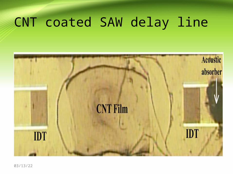
• CNT-coated SAW sensors used in this work monitor the gas concentration
by detecting the change in acoustoelectric coupling between the piezoelectr
ic SAW substrate and the CNT film deposited on the acoustic pathway
• This sensing methodology eliminated the common problems of hysteresis a
nd variability due to oxygen adsorption at the metal CNT junctions in the
widely researched CNT-FETs.
• Combined with their small size and radio-frequency operation, CNT-coated
SAW sensors show promise as a workable solution for portable, sensitive
wireless gas monitoring.
04/15/23
CNT coated SAW delay line

04/15/23
• Though CNT films may be drop coated by utilizing ionic surfactants adsor
bed on the nanotubes to uniformly disperse the CNTs in solution , such met
hods compromise the exposed nanotube area to incoming gases.
• Hence, surfactant-dispersed CNTs were not favored for this application.
• CNT films for gas sensing are required to have maximum surface area exp
osed to the incoming gas, a recently developed CNT coating technique for
transparent thin film actuators
• Subsequent self-assembly on oppositely charged substrates allowed fabrica
tion of uniform CNT films without interfering surfactant molecules in the f
ilm.
04/15/23
• Such films without surfactants presented a higher ratio of nanotubes/substr
ate area to incoming gases, thereby increasing their sensitivity.
• The horizontal random network of CNTs was tens of nanometer thick and t
hus was not likely to trap gases as might be expected for vertically grown
CNTs
• Hence the response time of the film to gas sensing was likely to be higher
• Acidified SWNTs: 100 mg of SWNTs from Times nano web (Chengdu,
China) with 30 ml of 96% H2SO4 and 10 ml of 69% HNO3 at 110oC for 7
0 min. The acid treated CNTs were subsequently diluted and filtered repeat
edly to wash away the residual acids
04/15/23
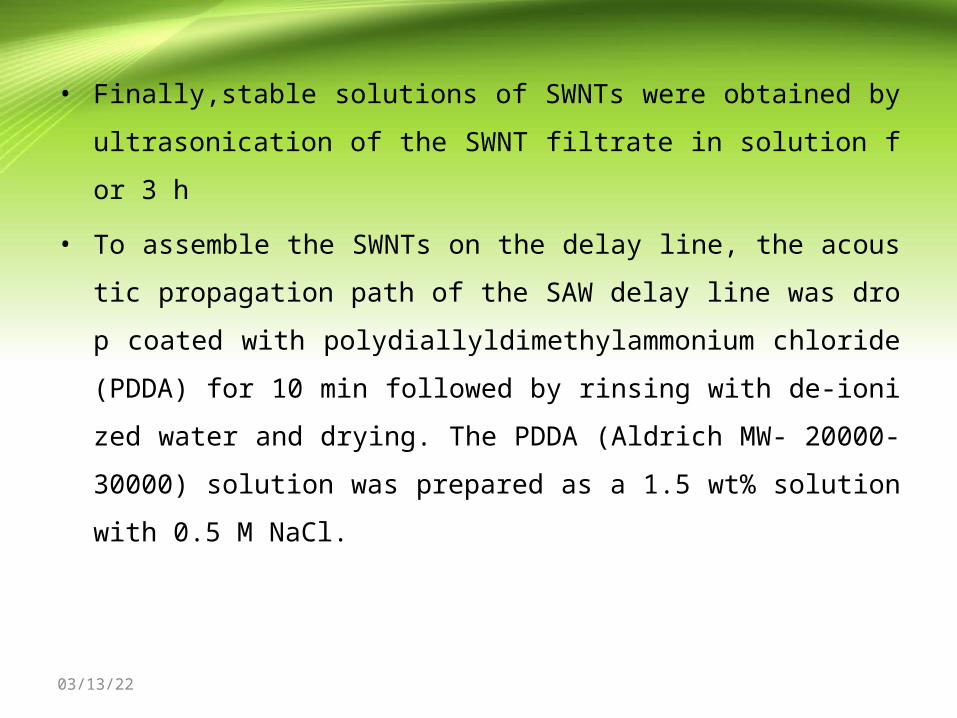
• Finally,stable solutions of SWNTs were obtained by ultrasonication of the
SWNT filtrate in solution for 3 h
• To assemble the SWNTs on the delay line, the acoustic propagation path of
the SAW delay line was drop coated with polydiallyldimethylammonium c
hloride (PDDA) for 10 min followed by rinsing with de-ionized water and
drying. The PDDA (Aldrich MW- 20000-30000) solution was prepared as
a 1.5 wt% solution with 0.5 M NaCl.
04/15/23
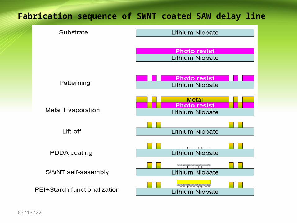
Fabrication sequence of SWNT coated SAW delay line
04/15/23
04/15/23
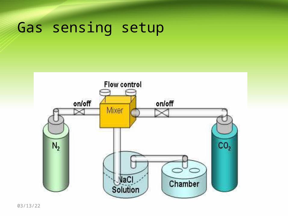
Gas sensing setup