nano-engineered catalyst for the utilization of co2 in dry ... library/research/coal/carbon...
TRANSCRIPT

Kickoff MeetingSeptember 12, 2017
Nano-engineered catalyst for the utilization of CO2 in dry reforming to produce syngas
DOE Contract No. DE-FE0029760
Shiguang Li, Gas Technology Institute (GTI)Xinhua Liang, Missouri University of Science and Technology (Missouri S&T)
2
2
Outline
Introduction to team members
Project overview
Technology fundamentals/background
Research plan
Preliminary results

3
Research organization, providing energy and environmental solutions to the government and industry since 1941
Facilities: 18 acre campus near Chicago
Introduction to GTI
Idea
Market Analysis
Technology Analysis
Product Development
Lab and Field Testing
Demonstration
Commercialization
OFFICE SUBSIDIARY

4
Introduction Missouri S&T
Co-educational research university located in Rolla, Missouri
Prof. Liang Group: expertise in atomic layer deposition thin coatings, catalyst preparation, characterization, and testing
Dr. Xinhua Liang
Zeyu Shang Xiaofeng Wang Yan Gao
Weston Shoemaker Han Yu Ye Jin

5
5
Project overview
Performance period: July 1, 2017 – June 30, 2020
Funding: $799,807 DOE ($199,990 co-funding), three year effort
Objectives: Develop nano-engineered catalyst supported on high-surface-area ceramic hollow fibers for the utilization of CO2 in dry reforming of methane (CO2 + CH4 → 2 H2 + 2 CO) to produce syngas
Team:
Member Roles• Project management and planning• Quality control, reactor design and testing• Techno-Economic Analysis (TEA ) and life cycle analysis (LCA)
Catalyst development and testing

6
Project organization and structure
DOE NETLProject ManagerProject oversight
GTIDr. Shiguang Li- PI
• Coordinate project activities• Project management
GTIMs. Kate Jauridez
Contract administrator
Missouri S&TDr. Xinhua Liang
• Catalyst development
GTIMr. Howard Meyer
• Project QA/QC
GTIMr. Travis Pyrzynski
• System modification and testing
GTIDr. James Aderhold
• Process simulation
GTIDr. Naomi Klinghoffer• Reactor design
7
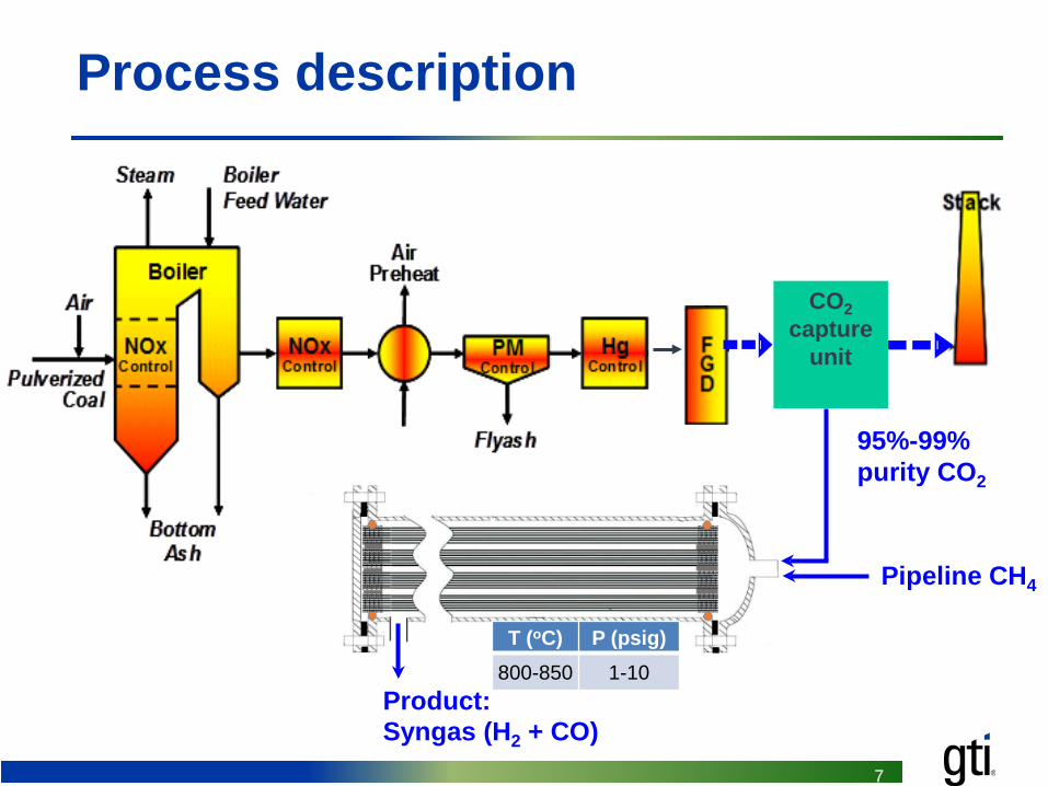
Process description
95%-99% purity CO2
CO2capture
unit
Pipeline CH4
Product:Syngas (H2 + CO)
T (oC) P (psig)800-850 1-10
88
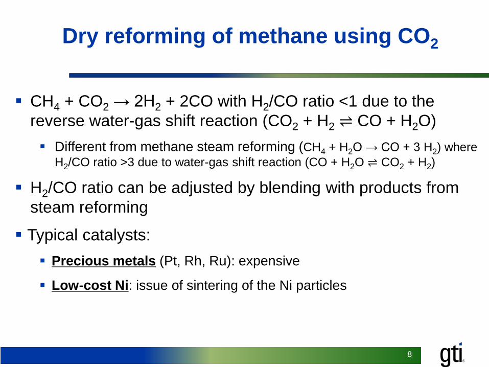
Background
CH4 + CO2 → 2H2 + 2CO with H2/CO ratio <1 due to the reverse water-gas shift reaction (CO2 + H2 ⇌ CO + H2O) Different from methane steam reforming (CH4 + H2O → CO + 3 H2) where
H2/CO ratio >3 due to water-gas shift reaction (CO + H2O ⇌ CO2 + H2)
H2/CO ratio can be adjusted by blending with products from steam reforming
Typical catalysts: Precious metals (Pt, Rh, Ru): expensive
Low-cost Ni: issue of sintering of the Ni particles
Dry reforming of methane using CO2

9
9
Bis(cyclopentadienyl)nickel, Ni(Cp2), used as a precursor
Self-limiting sequential surface chemical reactions Nickelocene
Ni(C5H5)2Al2O3 surface
OH OHNi Ni
O O
CxHy C5H5
A Al2O3 surface
HydrogenH2B Al2O3 surface Al2O3 surface
Ni Ni
O O
CxHy C5H5
CxHy C5H6
NiNiOH OH
Nickelocene:
Nano-engineered Ni catalyst prepared by atomic layer deposition (ALD)

10
10
TEM image of γ-Al2O3 spheres supported Ni catalysts
Ni particle size: 2-6 nm, average 3.6 nm Particles prepared by traditional methods are ~10-20 nm
Smaller nanoparticles can increase active sites
0
10
20
30
40
1 2 3 4 5 6 7
Freq
uenc
y, %
Particle diameter, nmZ. Shang, et al., Applied Catalysis B: Environmental, 2017, 201, 302-309

11
11
X-ray photoelectron spectroscopy (XPS) analysis indicates the presence of NiAl2O4
Z. Shang, et al., Applied Catalysis B: Environmental, 2017, 201, 302-309
850855860865870
Inte
nsity
Binding energy, eV
As deposited
Heated 550 ºC
NiO
NiAl2O4
Ni
Metallic Ni can be observed on as-deposited Ni/Al2O3catalyst
Metallic Ni was oxidized to NiO and NiAl2O4 when catalysts were calcined in air at 550oC

12
12
ResultsH2-Temperatrue programmed reduction (TPR) analysis
NiAl2O4 spinel would form in the Ni ALD process.
No NiAl2O4 spinel would form for Ni catalysts prepared by conventional method.
200 300 400 500 600 700 800 900
Hyd
roge
n co
nsum
ptio
n
Temperautre, °C
ALD Ni/dense Al2O3 NPs
IW Ni/porous ɤ-Al2O3
ALD Ni/porous ɤ-Al2O3
FreeNiO
NiO interactedwith support Non-stoichiometric
nickel aluminate
NiAl2O4
Z. Shang, et al., Applied Catalysis B: Environmental, 2017, 201, 302-309

13
13
Performance of ALD Ni/γ-Al2O3 catalyst
Catalyst was regenerated by oxidation and reduction between cycles Conversion stable at 850 ºC after 140 hours in 2nd cycle Only slight deactivation at lower temperatures (<3% in 50 hours)
0
20
40
60
80
100
0 50 100 150 200 250 300 350
Met
hane
con
vers
ion,
%
Time, hr
1st cycling
2nd cycling
3rd cycling
850 ℃850 ℃
800 ℃
700 ℃
850 ℃ 800 ℃
750 ℃
700 ℃

14
14
Advantages over traditional catalysts prepared by incipient wetness (IW)
Higher activity due to highly dispersed nanoparticles: ~3.6 nm Ni particles compared to ~10-20 nm particles prepared by traditional methods
Better stability due to strong bonding between nanoparticles and substrates since the particles are chemically bonded to the substrate during ALD
0
20
40
60
80
100
0 50 100 150 200
Meth
ane c
onve
rsion
, %
Time on stream, hr
1st cycle2nd cycle3rd cycle
850 ℃
850 ℃
800 ℃
750 ℃
700 ℃
850 ℃
800 ℃
750 ℃
700 ℃
0
20
40
60
80
100
0 50 100 150 200 250 300 350
Met
hane
con
vers
ion,
%
Time, hr
1st cycle
2nd cycle
3rd cycle
850 ℃850 ℃
800 ℃
700 ℃
850 ℃ 800 ℃
750 ℃
700 ℃
CatalystCH4 reforming rate (L·h-1gNi-1) H2/CO ratio in the product850°C 800°C 750°C 850°C 800°C 750°C
ALD 1840 1740 1320 0.82 0.78 0.68IW 1700 1150 480 0.70 0.61 0.51
ALD IW

15
15
Novel α-Al2O3 hollow fiber with high packing density is being used as catalyst substrate in current project
Catalyst Geometry SA/V (m2/m3)1-hole 1,1511-hole-6-grooves 1,7334-hole 1,70310-hole 2,013Monolith 1,3004-channel ceramic hollow fibers 3,000
Commercial substrates Novel α-Al2O3 hollow fibers Four channels, 35 cm long OD of 3.2 mm and a channel inner
diameter of 1.1 mm Geometric surface area to volume
as high as 3,000 m2/m3
Currently being tested in a packed bed reactor with catalyst supported on ~2-cm long fibers

16
16
In addition to packed bed reactor, a pressure-driven transport reactor will be designed and tested
1
2
Ceramic hollow fibers
O
Fiber internal surface, pores, and external surface deposited with catalysts for reactions:CO2 + CH4 → 2 H2 + 2 CO
Feed:CO2 + CH4 to bore (tube) side
Product: syngas (H2 + CO)Collected from the shell side
Dead end

17
17
Overview/roadmapTask 1: Project management and planning (throughout the project)
BP1(18 months)
Task 2.0 – Dry reforming catalyst (supported on ~1-2-cm long fibers) synthesis optimization, characterization and testing
Task 8.0 – Catalytic reactor performance testing of the two configurations
Task 6.0 – Further improvement of the hollow fiber supported catalyst
Task 3.0 – Modification of ALD reactor for coating catalysts onto 20-cm long hollow fibers
Task 5.0 – Evaluation of 20-cm hollow fiber supported catalyst performance
Task 7.0 – Design and construction of reactor containing multiple hollow fibers
Task 4.0 – Deposition of catalyst onto 20-cm long hollow fibers using viscous flow ALD
Task 11.0 – Life cycle analysis and technical and economic feasibility study
Task 10.0 – Catalyst deactivation and long-term stability tests
Task 9.0 – Catalyst support for deactivation and long-term stability tests
System Design/ModificationCatalyst Development
BP2(18 months)

18
18
Project funding profile
Budget Period 1 Budget Period 2Total Project
07/01/2017-12/31/2018 01/01/2018-06/30/2020
Government Share
Cost Share
Government Share
Cost Share
Government Share
Cost Share
GTI $70,026 $15,136 $329,775 $49,854 $399,802 $64,990
Missouri S&T $230,830 $66,813 $169,176 $68,187 $400,005 $135,000
Total $300,856 $81,949 $498,951 $118,041 $799,807 $199,990
Cost Share 79% 21% 81% 19% 80% 20%

19
19
MilestonesBudget Period
Task/Subtask Number
Milestone Title/Description Completion Date
Planned Actual1 1 Updated Project Management Plan. 08/31/17 07/03/171 1 Kickoff Meeting. 09/30/17 09/12/17
1 2 Catalyst showed CH4 conversion >90%, H2/CO ratio of 0.7-0.85, and CH4 reforming rate >2,200 L/h/gNi at 800ºC and 15-25 psia. 03/31/18
1 3, 4Hollow fiber supported catalyst showed CH4 conversion >95%, H2/CO ratio in the range of 0.7-0.85, and CH4 reforming rate >2,300 L/h/gNi at 800 ºC and pressure of 15-25 psia.
12/31/18
1 5 200 hours testing showed CH4 conversion decrease less than 20% at 800ºC and pressure of 15-25 psia. 12/31/18
1 1 Submit Continuation Application. 10/01/18
2 6 20 pieces of 20-cm long hollow fibers coated with catalysts shipped to GTI for testing in catalytic reactor. 09/30/19
2 7 Reactors containing multiple hollow fibers passed commissioning testing. 03/31/19
2 8 Catalytic reactor showed CH4 conversion >95%, H2/CO ratio of 0.7-0.85, and CH4 reforming rate >2,200-2,500 L/h/gNi at 800ºC. 09/30/19
2 9,10 200 hours testing in catalytic reactor showed conversion decrease less than 10% at 800ºC. 06/30/20
2 11 Issue topical report on technical and economic feasibility and life cycle analysis 06/30/20
2 1 Submit Final Technical Report. 07/30/20

20
20
Success criteria
Decision Point Date Success Criteria
Go/no-go decision points
12/31/18
1) Fiber supported catalyst shows CH4 conversion >95%, H2/CO ratio of 0.7-0.85, and CH4 reforming rate >2,300 L/h/gNi at 800 ºC and 15-25 psia
2) 200 hours testing shows CH4 conversion decrease less than 20% at 800ºC and 15-25 psia
Completion of the
project6/30/20
1) Catalytic reactor shows CH4 conversion >95%, H2/CO ratio of 0.7-0.85, and CH4 reforming rate >2,200-2,500 L/h/gNi at 800ºC
2) 200 hours testing shows conversion decrease less than 10% at 800ºC
21
21
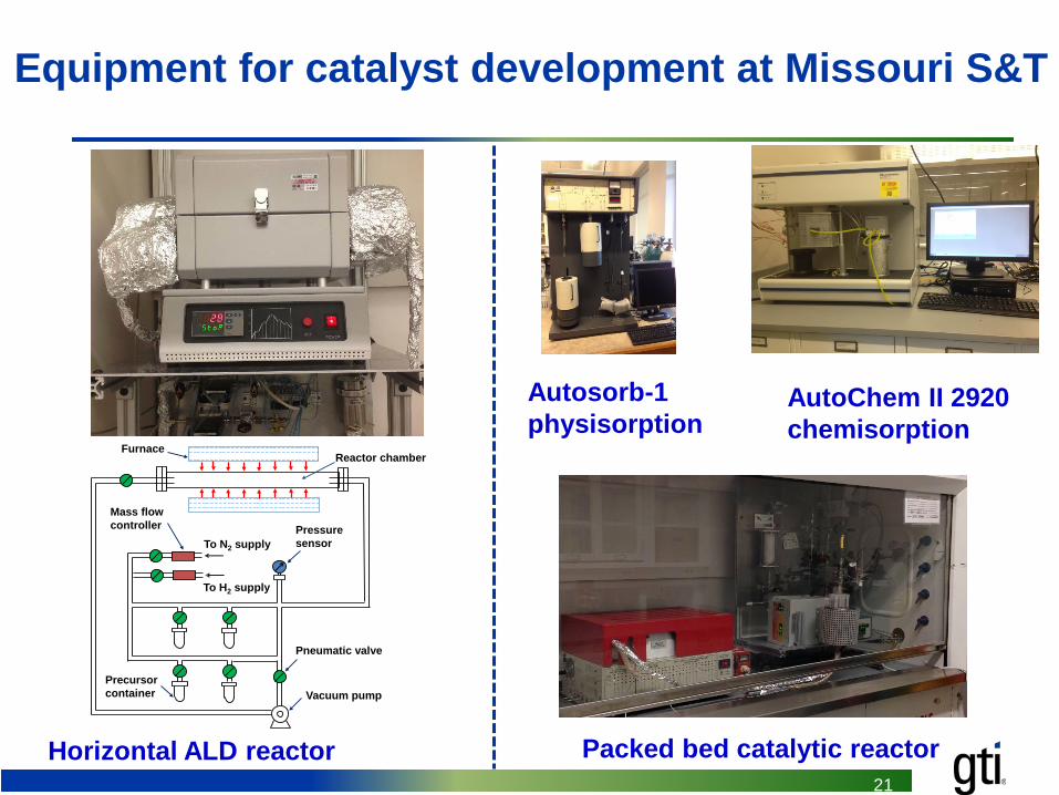
Equipment for catalyst development at Missouri S&T
Mass flow controller
To N2 supply
Vacuum pump
Pressuresensor
To H2 supply
Pneumatic valve
Precursor container
Reactor chamberFurnace
Horizontal ALD reactor Packed bed catalytic reactor
Autosorb-1 physisorption
AutoChem II 2920 chemisorption

22
22
Catalyst development strategies
Current statusALD Ni/α-Al2O3 hollow fiber (1-cm long)
ImprovementALD Ni/α-Al2O3 hollow fiber (1-cm long)
Scale-upALD Ni/α-Al2O3 hollow fiber (20-cm long)

23
23
Equipment for catalyst testing at GTI

24
Challenges/Risks1) Longer-term stability of catalyst
Mitigation: 1a: Address any issues observed during
a 200-hour testing 1b: Develop a catalyst regeneration
process
2) Catalytic reactor sealing/pottingMitigation: 2a: Use advanced potting materials 2b: Leave the potting ends in a lower
temperature zone
3) Pressure-driven transport configuration not as good as expected
Mitigation: 3a: Alternate designs
Risk summary
Consequence
Like
lihoo
d
1 2 3 4 5
1
2
3
4
5 1
21a
1b 2a
2b
3
3a
Preliminary risk assessment: technical challenges and mitigation strategies

25
25
Preliminary results: ALD Ni/α-Al2O3 hollow fiber shows higher CH4 reforming rate than ALD Ni/γ-Al2O3
CatalystCH4 reforming rate (L·h-1gNi-1)
850°C 800°C 750°C 700°C
ALD Ni/γ-Al2O3 porous sphere 1840 1740 1320 720
ALD Ni/α-Al2O3 hollow fiber 1970 2040 1770 980

26
Plans for future development
In this project Project just started, will focus on project work and meeting
milestones
After this project Test with real captured CO2 from our CO2 capture system

27
27
Summary
We are developing ALD nano-engineered catalysts for utilization of CO2 in dry reforming of methane to produce syngas
ALD nano-engineered catalyst improves catalytic activity and stability
Novel α-Al2O3 hollow fiber increases surface area, and enables pressure-driven transport reactor configuration
Preliminary study indicated that Ni catalyst supported on α-Al2O3 hollow fiber had higher reforming rate than that on the γ-Al2O3 porous particles
CatalystCH4 reforming rate (L·h-1gNi-1)
850°C 800°C 750°C 700°C
ALD Ni/γ-Al2O3 porous particles 1840 1740 1320 720
ALD Ni/α-Al2O3 hollow fiber 1970 2040 1770 980
0
20
40
60
80
100
0 50 100 150 200 250 300 350
Meth
ane c
onve
rsion
, %
Time, hr
1st cycling
2nd cycling
3rd cycling
850 ℃850 ℃
800 ℃
700 ℃
850 ℃ 800 ℃
750 ℃
700 ℃

28
Acknowledgements
Financial and technical support
NETL Project Manager Bruce Lani
DE-FE0029760