nano and r2 nano the world's strongest thermal bridging …marmox.com/products/61.pdf · ·...
TRANSCRIPT

Stop Thermal bridging at the root
Nano and R2 NanoThe world's strongest Thermal Bridging Block
Use where the wall meets the floorDifferent widths availableLight weight to handleEasy to use
56
INSU
LATI
ON
SO
LUTI
ON
S
Insulation solutions

57
Heat camera shows in red the main area whereheat is lost from a house
What is Marmox THERMOBLOCK ?®
®
®
2
2
polymeric cement mortar
Fiber glass mesh
(nano) polymeric concrete
extruded polystyrene foam
Fiber glass mesh
polymeric cement mortar
What are thermal bridges?
Thermal bridges can occur at various locations in the building envelope. They result in increased heat flow, which in turn causes additional transmission heat loss, lower internal surface temperatures, and possible condensation and mold problems. The additional transmission heat loss drives up energy consumption, an especially important issue as we move towards low-energy housing and passive houses, and further in the future towards near-zero energy homes. Indeed, research has shown that heat loss due to thermal bridges can be so high that it cannot be offset by the energy gained through solar water heating. Thermal bridges generally have a significant overall impact on heat-energy demand, driving up consumption by as much as 30%!
What is Marmox Thermoblock®?
Marmox THERMOBLOCK is a patented insulating part, comprising a core of extruded polystyrene foam (XPS) containing regularly spaced load-bearing (nano) polymeric concrete cylinders. The upper and lower sides are covered with polymeric cement, reinforced with a fiberglass mesh.
This unique structure gives Marmox THERMOBLOCK a number of exceptional properties:
• R -value = 2 m k/W at just 6 cm thickness• Compressive strength ≥ 6 N/mm• Watertight• Lightweight• Easy to work with

58
INSU
LATI
ON
SO
LUTI
ON
S
Insulation solutions
Color image
Cross sectionof a nanotube
Variousnanotubes
What is nanotechnology?
Nanotechnology makes it possible to work with parts measured in nanometers (a billionth of a meter). This is a scale just above that of atoms (0.060 nm to 0.275nm) and simple molecules. One criterion is that the structure must measure less than 100 nanometers in at least one dimension.
A nanotube is an elongated nanostructure in the form of a hollow cylinder, usually made from carbon. Nanotubes come in various types, the best known of which is the carbon nanotube.
This is a rolled-up layer of graphite, hollow inside, with a length ten thousand times greater than its diameter.
Carbon nanotubes (CNTs) were discovered in the early 1990s. CNT length is measured in micrometers, with diameters less than 100 nm and usually close to 10 nm, depending on the synthesis process. CNTs have a single wall (SWNTs), a double wall (DWNTs) or multiple walls (MWNTs), depending on the number of layers (the C is often omitted in these abbreviations).
In their pure state, CNTs have exceptional mechanical, electrical and thermal properties. Once good CNT dispersion has been obtained, a very low concentration is needed to radically improve the mechanical properties of the material, among other things. The optimal dispersion percentage is usually between 0.1% and 2%.
The load-bearing (nano) polymeric carbon cylinders in Marmox THERMOBLOCK nano and R2 nano are a direct application of the above technology. The use of Graphistrength MWNT (carbon nano-tubes with 10 to 15 walls with an average outer diameter of 12 nm) in the polymeric concrete leads to mechanical strengthening of the composite material and a perfect balance between λ-value and compressive strength.
®
®

59
Why choose Marmox Thermoblock as insulating part?
Belgisch Staatsblad/Moniteur belge - 08.12.2010
In Flanders (the other Belgian Regions are expected to follow shortly) from 1 January 2011 the EPB reporter must allow for the impact of nodes on the K-level for new buildings subject to a planning permit application or a report.
The compulsory method for determining the impact of nodes on the transmission heat loss coefficient is laid down in appendix VIII “Behandeling van bouwknopen” in Belgisch Staatsblad/ Moniteur belge (08.12.2010). Three methods are provided: a detailed method (Option A), a method of EPB-accepted nodes (Option B) and a method in which a fixed penalty is placed on the K-level (Option C).
Numerical calculations with validated software (Option A) are very labor-intensive and demand specialized know-how and software. If no effort is made to limit heat loss at the nodes (Option C) the unknown impact of the nodes on the total heat loss is established by means of a fixed penalty on the K-level of 10 K-points. In practice, as research has shown, Option B will most often be chosen.
It is important to note that, like the other options, Option C in no way absolves the building team from the responsibility to minimize the risk of mold growth and condensation.
In Option B, a fixed K-level penalty of 3 K-points is allocated for ‘EPB-accepted nodes’. These are nodes whose specific features do not cause improper heat loss and that can therefore be considered as nodes with low thermal conductivity. No lengths and/or quantities need to be established for these nodes, which mean that calculations can be limited. Option B proposes two ways for ensuring a node is ‘EPB-accepted’:
• The node complies with the applicable limit values.• The node satisfies one of the three basic rules for thermal bridge features.
Research has shown that more than 50% of all designers prefer to work with Option B and Basic Rule 2 (Insertion of insulating parts).
®

60
INSU
LATI
ON
SO
LUTI
ON
S
Insulation solutions
Basic Rule 2: insertion of insulating parts
This basic rule applies to nodes where the insulation layers do not (cannot) interconnect, although the possibility of inserting insulating parts does exist.These insulating parts assume the thermal insulating function of the insulating layers locally, ensuring the continuity of the thermal break, such as at the junction of a flat roof and an exterior wall or the foundations.
Basic Rule 2 proposes that all insulating parts must satisfy all 3 of the followingrequirements:
The λ-value of both the extruded polystyrene foam (λ= 0,030 W/mK) and the (nano) polymeric concrete (λ = 0,165 W/mK) in Marmox THERMOBLOCK is less than 0.2 W/mK, so this requirement is satisfied. Furthermore, given that the volume share of the (nano) polymeric concrete is ≤ 10% per running meter of linear node, this can be viewed as a permitted local interruption of the insulating part, as a consequence of which λ is fixed at 0.030 W/mk.
The R-value requirement states that the thermal resistance R of the insulating part is ≥ half of R1 or R2, whichever is lowest (where R1 and R2 are the thermal resistances of the connecting insulation layers). To ensure this requirement remains feasible in the event of very high values of R1 and R2 (thick insulating layers), an upper limit is imposed on R: 2 m K/W. Marmox THERMOBLOCK R2 nano has an R-value = 2 m K/W and so always provides a sound solution that does not require any further calculations.
Where an insulating part (with a given thickness) connects to an insulating layer or another insulating part (with a given thickness), the contact length must be ≥ half of the smallest of the two thicknesses. Subject to the correct features, Marmox THER-MOBLOCK can always satisfy this requirement (see pp. 63, 64, 65 and 66).
®
insulating part
2 ®
®
2

61
KOBRA - Calculation results
f = 0,876
Q2D = 20,372 W/m
L2D = 1,019 W/(mK)
l1 = 0,980 m
l2 = 1,325 m
U1 = 0,328 W/(m K)
U2 = 0,606 W/(m K)
psi = -0,106 W/(mK)
Ueq = 0,442 W/(m K)
The calculation results show that an excellent temperature factor f is obtained as well as an advantageous negative Ψ-value.
Figure1: Graphical depiction of materials of the foundation
Figure 2 : Graphic depiction of temperatures of the foundation (with heat streamlines)
Psi value Ψ and temperature factor f
The thermal performance of an insulating part in a node is characterized by the linear thermal transmittance Ψ (in W/mK). This thermal transmittance indicates which penalty (difference between the numerical two-dimensional reference based on the overall dimensions) must be imposed on the thermal transmission calculated on the basis of U-values. Ψ-values can be negative when the reference calculation overestimates the actual heat flow.
The temperature factor f is an indicator of the lowest internal surface temperature θ at a feature, where θ is the internal temperature and θe the external temperature. The temperature factor f has a value between 0 and 1. If the internal surface temperature is too low, surface condensation and mold growth may occur.Depending on the building type, minimal values are presupposed for f ≥ 0.80.
By way of example, the calculation of both the Ψ-value and the temperature factor f for a typical application such as the foundation is presented below, with use of the Marmox THERMOBLOCK R2 nano and Styrodur C in cavity (80 mm) and floor (40 mm). A graphical depiction of the feature with isotherms and heat streamlines can be obtained using Physibel’s KOBRA software, which is free to download from the WTCB.
Ѳ – ѲF =
si
Ѳ – Ѳi e
esi i
® ®
2
2
2

62
INSU
LATI
ON
SO
LUTI
ON
S
Insulation solutions
600
53
15
1.5
1.53030
64 64
40.5
19.5
90
110
21.6
58.4
85.7
24.3
140
190
28.3
131.7
92
92
26
28.6
115.7
115.7
290
240
1.5
2525
63
1.5
RANGE
Marmox THERMOBLOCK is available in 2 thicknesses (50 and 60 mm) and 6 breadths (90, 110, 140, 190, 240 and 290 mm), whereas the usable length is always 600 mm(615 mm in total).
Marmox THERMOBLOCK nano has a thickness of 50 mm. Marmox THERMOBLOCK R2 nano has a thickness of 60 mm.
®
® ®

Features
Insulating parts assume the thermal insulation function of the insulation layers locally where the insulation layers do not interconnect directly, but it is possible to insert insulating parts.As a consequence, the thermal break can be retained, such as at the foundation or at the connection with a flat roof. That avoids improper heat losses and prevents con-densation and mold problems.
Foundation above crawl space (floor insulation --> hard insulation plate)
63
1 Facing brick Cavity Insulation High-speed building brick 288x138x138 Interior plastering2 Floor finish + screed Hard insulation plate In-fill screed Floor elements in reinforced concrete3 Stahlton lintel or equivalent for filling4 Hollow concrete block 390x290x1905 Full concrete block 290x90x906 Full concrete block 290x90x1407 Cementing8 Bituminous sealing layer9 DPC foil10 Watertight cementing behind plinth11 Edge strip in PE foam12 Marmox THERMOBLOCK R2 nano
®

Foundation above crawl space
(floor insulation --> PUR insulation sprayed in situ)
64
INSU
LATI
ON
SO
LUTI
ON
S
Insulation solutions
1 Facing brick Cavity Insulation High-speed building brick 288x138x138 Interior plastering2 Floor finish + screed PUR insulation sprayed in situ Floor elements in reinforced concrete3 Hollow concrete block 390x290x1904 Full concrete block 290x90x905 Cementing6 Bituminous sealing layer7 DPC foil8 Watertight cementing behind plinth9 Edge strip in PE foam10 Marmox THERMOBLOCK R2 nano®

Flat roof edge
65
1 Facing brick Cavity Insulation High-speed building brick 288x138x138 Interior plastering2 Roof seal Insulation Any waterproof layer Concrete for slopes Concrete bearing floor Interior plastering3 High-speed building brick 288x138x1384 Cap stone5 Cavity cover6 High-speed building brick 288x138x1887 Angle slat8 Marmox THERMOBLOCK R2 nano
4
56
7 8
≥ 15 cm
8
804
150↓50
130
15
23
1
scale = 1:10
90 80 140 1530
®

Flat roof/rising cavity wall connection
66
INSU
LATI
ON
SO
LUTI
ON
S
Insulation solutions
1 Facing brick Cavity Insulation High-speed building brick 288x138x138 Interior plastering2 Roof seal Insulation Any waterproof layer Concrete for slopes Concrete bearing floor Interior plastering3 High-speed building brick 288x88x1384 High-speed building brick 288x88x885 Metal slab6 Angle slat7 Marmox THERMOBLOCK R2 nano®
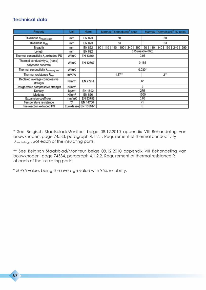
Technical data
* See Belgisch Staatsblad/Moniteur belge 08.12.2010 appendix VIII Behandeling van bouwknopen, page 74533, paragraph 4.1.2.1. Requirement of thermal conductivityλ of each of the insulating parts.
** See Belgisch Staatsblad/Moniteur belge 08.12.2010 appendix VIII Behandeling van bouwknopen, page 74534, paragraph 4.1.2.2. Requirement of thermal resistance Rof each of the insulating parts.
° 50/95 value, being the average value with 95% reliability.
67
insulating part

Packaging
68
INSU
LATI
ON
SO
LUTI
ON
S
Insulation solutions
69
• Installation should always be carried out on a level base, with the introduction below and above the Marmox THERMOBLOCK of a completely level mortar bed of 12-15 mm to ensure a full connection. That means that the mortar bed must be introduced at the top and at the bottom across the full breadth and length.
• If Marmox THERMOBLOCK is installed as a bottom layer; it should be installed perfectly level in a mortar bed. This takes care of the irregularities in the base. The mortar for the mortar bed is a traditional mortar based on 9 parts sand and 3 parts cement. Ensure the mortar is not too wet (water/cement-factor = 0.7), as it is thicker than a regular masonry joint. Add Addibond 65 to the mixing water to improve the adhesive power of the mortar.
• Marmox THERMOBLOCK must not be used in more than one adjacent layer, with or without mortar joint.
• Always use a Marmox THERMOBLOCK with a breadth equal to the breadth of the wall.
• Marmox THERMOBLOCK can be installed below or directly above the first masonry layer on the basis of brick, concrete blocks or sand-lime brick.
• If concrete blocks are used, the concrete blocks below or above the Marmox THER-MOBLOCK must be of the full type. If hollow concrete blocks are used, any layer below or above the Marmox THERMOBLOCK should be turned around and filled with mortar or concrete cement.
• For uses in combination with glued or mortared aerated concrete, please contact us.
• If bituminous membranes have to be introduced on or against the product with a flame, the flame-resistant version (Marmox THERMOBLOCK R2 nano/pir) must be used. This is available on request.
• To ensure a perfect watertight connection between the blocks, use MS polymer kit (type TEC7®) in the groove/joint.
Installation guidelines
®
®
®
®
®
®
®
®

70
INSU
LATI
ON
SO
LUTI
ON
S
Insulation solutions
Specifications text
Description :
The low thermal-conductivity featuring of the nodes is achieved with a patented insulating part (Marmox THERMOBLOCK ) comprising a core of extruded polystyrene foam (XPS) with regularly spaced load-bearing (nano) polymeric concrete cylinders. Upper and lower sides are covered with a polymer cement mortar, reinforced with fiberglass meshing.
Material :
Thickness: 50 mm (Marmox THERMOBLOCK nano) 60 mm (Marmox THERMOBLOCK R2 nano)• Breadth: 90 – 110 – 140 – 190 – 240 – 290 mm• Length: 615 mm total (600 mm usable)• Thermal conductivity λ = 0.030 W/mK according to appendix VIII• Declared average compressive strength = 6 N/mm²• Design value compressive strength = 2 N/mm²• Density 275 kg/m³The insulating part is packed in cardboard boxes.The relevant details are stated on the label of each packaging unit.
Installation :
Installation should be carried out in the accepted manner and in accordance with the manufacturer’s instructions.
®
®
®
insulating part