name and address of certificate holder: performance...
TRANSCRIPT

Rapid Panels
User should check the
validity of the Certificate by contacting Member
Secretary, BMBA at
BMTPC or the Holder of
this Certificate.
Name and Address of Certificate Holder:
M/s Worldhaus Construction
Pvt. Ltd.
No. 102/5, 7th ‘A’ Main,
3rd Block, Jayanagar
Bangalore -- 560011
Performance Appraisal
Certificate No.
PAC No 1026-S/2016
Issue No. 01
Date of Issue: 08.04.2016
Building Materials & Technology Promotion Council Ministry of Housing & Urban Poverty Alleviation
Government of India
Core 5A, First Floor, India Habitat Centre,
Lodhi Road, New Delhi – 110 003 Tel: +91-11-2463 8096, 2463 8097; Fax: +91-11-2464 2849
E-mail: [email protected] Web Site: http://www.bmtpc.org


2
CONTENTS
PART 1 CERTIFICATION……………………………………………………………………………. 3
1.1 Certificate Holder …………………………………………………………………. 3
1.2 Description of System …………………………………………………………….. 3
1.3 Design Considerations…………………..………………………………………… 4
1.4 Production Machinery …………………………………………………………….. 5
1.5 Manufacturing Process ……………………………………………………………. 6
1.6 Basis of Assessment …………………………………………………………….... 6
1.7 Use & Limitations of the System …………………………………………………. 7
1.8 Conditions of Certification ……………………………………………………….. 7
1.9 Certification ……………………………………………………………………… 8
PART 2 CERTIFICATE HOLDER’S TECHNICAL SPECIFICATION………………………….. 8
2.1 General…………………………………………………………………………….. 8
2.2 Specifications of the System……………………. ………………………………… 9
2.3 Production Stages …………………………………………………………………. 11
2.4 Implementation ……………………………………………………………………. 11
2.5 Transportation, Handling & storage ………………………………………………. 31
2.6 Inspection and Training …………………………………………………………… 33
2.7 Good Practices for Installation & Maintenance …………………………………… 33
2.8 Maintenance Requirements ………………………………………………………... 33
2.9 Skills/ training needed for installation …………………………………………….. 33
2.10 Guarantees/Warrantees Provided by.……………………………………………... 33
2.11 Responsibility ……………………………………………………………………. 33
PART 3 BASIS OF ASSESSMENT AND BRIEF DESCRIPTION OF ASSESSMENT
PROCEDURE …………………………………………………………………………………………..
34
3.1 Assessment ………………………………………………………………………… 34
3.2 Site Inspection ……………………………………………………………………... 34
3.3 Tests Performed …………………………………………………………………… 34
3.4 Execution of Projects ……………………………………………………………… 36
PART 4 STANDARD CONDITIONS ………………………………………………………………… 38
PART 5 LIST OF STANDARDS AND CODES USED IN ASSESSMENT………………………… 40 CERTIFICATION …………………………………………………………………............................... 41
PART 6 ABBREVIATIONS …………………………………………………………………………… 42
PERFORMANCE APPRAISAL CERTIFICATION SCHEME – A BRIEF…………………... 43
ANNEX I FLOW CHART ………………………………………..…………………………………… 44
ANNEX II QAP ….…………………………………………………………………………………….. 45
ANNEX III PRODUCTION STAGES ……………………………………………………………….. 46
ANNEX IV TYPICAL DESIGN ………………………………………………………….. 48
3
PART 1 CERTIFICATION
1.1 Certificate Holder
Worldhaus Construction Pvt. Ltd.
No. 102/5, 7th ‘A’ Main, 3rd Block
Jayanagar
Bangaluru -- 560011
Tel: 09740916023, 08050268566
Email: [email protected]
1.2 Description of system
1.2.1 Name of the System – Rapid Panel
1.2.2 Brand Name – WorldHaus
1.2.3 Brief Description
The Rapid Panel is a prefabricated assembly of high-strength steel
wire forming a panel with a core of expanded polystyrene (EPS).
During construction, Rapid Panels are installed as walls and/or
slabs. Specified mixtures of mortar or concrete are applied to the
surfaces of the panels to complete the structure.
The basic unit of the Rapid Panel is the zig-zag truss. Steel wire is
bent into a zig-zag shape to form a continuous chain of web
members. This bent wire is then welded to continuous chord wires
at every node to form the complete truss. (See Fig. 1)
The Rapid panels are manufactured in a fully automated plant.
This technology was initially developed in USA and the Indian
firm has a collaboration with WorldHaus, California, USA.
The Rapid panels are manufactured in Mexico and there is no plant
in India at present.

4
Fig. 1 Rapid Panel
1.3 Design Considerations
1.3.1 Structural design and analysis of Rapid panels shall be based on
relevant Indian and International standards. The design loads shall
not exceed the values given in Table 1 except where additional load
is provided. The panel construction assembly shall be used for free
standing walls when designed and anchored as cantilever walls.
Panels shall be reinforced and tied at vertical joints to maintain
alignment. Additional reinforcement and cement plaster shall be
provided as required by the design.
The technology is intended for use where Architectural drawings
are available. The Architect and Engineer designer team of the
concerned developer/owner (client) is responsible for the drawings
and overall building design to comply with the various regulatory
requirements applicable to the area.
1.3.2 The design assumptions, detailed calculations, references to
necessary and detailed design drawings shall be made available on
demand, if required. The structural design calculations should
clearly demonstrate structural integrity and stability including
connection details. Design calculations should have proper
sketches annotated in English.
1.3.3 Foundation shall be specifically designed in accordance with
provisions given in IS 1904:2005. All foundations should be
designed by structural engineer with appropriate reference.

5
1.3.4 In addition, any other requirement regarding safety against
earthquake need to be ensured by the designer as per prevailing
codal requirements.
A typical Design and Structural analysis of G+3 storey building
using Rapid panels is attached at Annex IV.
1.4 Production Machinery and Equipment
There is no manufacturing plant in India at present. The panels are
manufactured in Mexico and are imported as per requirement. The
information is based on the papers submitted by the firm.
The machinery (not verified by BMTPC) are:
Truss Machine: The truss machine takes spools of steel wire and
welds them into trusses of a specified length and width. It consists
of three components:
Six spools for staging the steel wire fed into the machines
(three wires for each truss).
A machine that pulls wire off the spools and straightens it.
The truss machine itself.
Assembly Carts: Alternating layers of truss and EPS strips are
placed in this cart to assemble the panel in preparation for the panel
assembly welder.
Panel Assembly Welder: The panel assembly welder takes the
assembled panel on the assembly cart, draws in cross wires from
spools, and welds them to the panel. It consists of two components:
Two spools for staging the steel wire fed into the machine
(one wire for either side of the panel).
The panel assembly welder itself.
Hand Repair Station: The hand repair station is essentially a table
and a hand held welder that allows the operator to create the
continuous connection part of the panel and repair any incomplete
welds from the panel assembly welder.
Support Equipment: This section includes any equipment or
services required for manufacture that do not rely on specialized
equipment.

6
1.5 Manufacturing Process
The manufacturing process of the panels shall be as follows:
The shop-fabricated panels shall consist of welded wire zig-zag
trusses and a foam plastic core to which structure plaster shall be
applied on each side. The panels shall have vertical 75 mm (3 inch)
deep 14 gauge (2.03 mm) wire trusses spaced at 50 mm (2 inch)
centers with preformed 57 mm (2 ¼ inch) thick expanded
polystyrene (EPS) foam strips between. The assembly shall be held
together with 14 gauge (2.03 mm) horizontal wires on each face at
50 mm centers electro welded to the truss chords. The horizontal
wires and vertical truss chords shall project 10 mm (3/8 inch)
approx. beyond each foam plastic face to permit wire embedment
within cement and gypsum plaster finish applied to each face after
erection on the site.
The panels shall be manufactured in 1.22 m (4 feet) widths and
varying heights from 1.52 m to 3.55 m (6 feet to 14 feet) in
increments of 100 mm. The nominal thickness of the panel shall be
75 mm resulting in a finished wall thickness, after plastering, of
100 mm or more. The Rapidpanels are manufactured in a fully
automated plant.
1.6 Basis of Assessment
1.6.1 Scope of Assessment
Scope of assessment includes conformance of manufactured wall
and floor/roof panels to the specified requirements for use in the
building construction.
1.6.2 Assessment
Assessment of the suitability of the Rapid Panel is based on:
i) Inspection of the under construction/constructed buildings
during visit of some of TAC members and Officers of
BMTPC at Bangalore
ii) Test Report of EPS and Galvanized high strength steel bars
by Civil-Aid Technoclinic Pvt. Ltd., Bangalore and Shriram
Industrial Research Institute, Delhi
iii) Test report of Load tests on Roof Panels by IIT Madras
iv) Test Report on Wall Panel by Civil-Aid Technoclinic Pvt.
Ltd., Bangalore
v) Test Report on Steel Bars by Karnataka Test House Pvt. Ltd.,
Bangalore

7
vi) Legacy Report by ICC Evaluation Services Inc., USA
vii) Construction Manual by WorldHaus Construction Ltd., USA
viii) Quality Assurance Procedure followed by the
Certificate Holder for quality control of the system as per the
Quality Assurance Plan enclosed at Annex II.
1.7 Use and Limitations of the Rapid Panels
1.7.1 The panels shall be used for construction of buildings consisting of
frame structures, load bearing walls, floors and roof etc. for
residential purposes up to G+3 storey.
1.7.2 Limitations of Use
i. Panel lengths shall be up to 5 m, simply supported on beams
or bearing walls not less than 125 mm in width
ii. Panels shall be installed with min. M20 grade of concrete
and 1:3 cement plaster
iii. Total dead load (including panel self-weight) shall not
exceed 3.3 kN/m2
iv. Total imposed load (live load) shall not exceed 3.0 kN/m2.
1. 8 Conditions of Certification
1.8.1 Technical Conditions
1.8.1.1 Raw materials and the finished panels shall conform to the
requirements of the prescribed specifications.
1.8.1.2 The building to be constructed using the Rapid Panels shall be
designed by competent structural engineers in accordance with the
specifications, following relevant codal requirements,
manufactured as per the details worked out in design and
constructed by trained persons only with technical support or
supervision by qualified engineers and builders, based on structural
designs and seismic evaluation & wind forces as per the details
given and this PAC.
The structural engineers and building designers associated with
such type of construction should be thoroughly familiar with the
various structural aspects. It is also recommended that Architects
and Construction Engineers who undertake such building design
and construction gain familiarity with the properties and materials,
characteristics of Rapid Panels and its applications.
8
The design assumptions, detailed calculations, references to
necessary and detailed design drawings shall be made available on
demand, if required. The structural design calculations should
clearly demonstrate structural integrity and stability including
connection details.
1.8.2 Setting up of Plant in India
The Certificate holder shall inform BMTPC as and when any plant
is set up in India. The panels from new set up will be allowed to be
used for this Certification purpose only after it fulfils the
requirements given in this Certification .
1.8.3 Quality Assurance
The Certificate Holder shall implement & maintain a quality
assurance system in accordance with Scheme of Quality Assurance
(SQA) given in the Annex II attached with this Certificate.
1.8.4 Durability
The Certificate Holder shall provide necessary structural warranty
ensuring durability of the system to the user, on demand.
1.8.5 Handling of User Complaints
1.8.5.1 The Certificate holder shall provide quick redressal to consumer/
user complaints proved reasonable & genuine and within the
conditions of warranty provided by it to customer/purchaser.
1.8.5.2 The Certificate holder shall implement the procedure included in
the SQA. As part of PACS Certification he shall maintain data on
such complaints with a view to assess the complaint satisfaction
and suitable preventive measures taken.
1.9 Certification
On the basis of assessment given in Part 3 of this Certificate &
subject to the conditions of certification, use & limitations set out
in this Certificate and if selected, installed & maintained as set out
in Part 1 & 2 of this Certificate, the system covered by this
Certificate is fit for use set out in the Scope of Assessment.
PART 2 CERTIFICATE HOLDER’S TECHNICAL SPECIFICATIONS
2.1 General
The PAC holder shall manufacture the panels in accordance with
the requirements specified.

9
2.2 Specifications of the Rapid Panels
2.2.1 Specifications
Specification for the raw materials and finished panels shall be as
per performance criteria when tested in accordance with the
company standard & relevant Indian/ International Standards listed
in this Certificate.
2.2.2 Specifications of Raw Materials
1. Galvanised high strength steel wire: Fe 500 & Fe 550 as per
IS 1786: 2008 having following characteristics:
(a) For Slab Panel
(i) Dia.
Top wire: 2.65 mm
Top distribution wire: 1.9 mm
Truss wire: 2.65 mm
Bottom wire: 5 mm
Bottom distribution wire: 1.9 mm
(ii) Mechanical characteristics
1.9 mm dia
Yield strength : 680 N/mm2
UTS : 687 N/mm2
Elongation : > 4.8 %
2.65 mm dia
Yield strength : 618 N/mm2
UTS : 632 N/mm2
Elongation : > 6.1 %
5 mm dia
Yield strength : 670 N/mm2
UTS : 816 N/mm2
Elongation : > 14 %
(iii)) Chemical characteristics
C % < 0.153, P % < 0.016, S % < 0.015, Mn % < 0.893, Si % <
0.134

10
a) For wall Panel
(i) Dia
Top wire: 2.65 mm
Top distribution wire: 1.9 mm
Truss wire: 2.65 mm
Bottom wire 2.65 mm
Bottom distribution wire: 1.9 mm
(ii) Mechanical characteristics
1.9 mm dia
Yield strength : 680 N/mm2
UTS : 687 N/mm2
Elongation : > 4.8 %
2.65 mm dia
Yield strength : 618 N/mm2
UTS : 632 N/mm2
Elongation : > 6.1 %
(iii)) Chemical characteristics
C % < 0.153, P % < 0.016, S % < 0.015, Mn % < 0.893, Si % <
0.134
2. Expanded Polystyrene (EPS): Self-extinguishing type EPS
shall conform to IS 4671:1984 and shall have following
characteristics:
Density: Shall be not less than15 kg/m3.
Flammability: Non Flammable
Moisture Continent at 50ºC: less than 1.1 %
Thickness: not less than 50 mm
Bead size: shall be > 95% between 0.5 – 1.12 mm as per
ASTM C 578
Environmental hazardous Substances:
Lead: <1 ppm, Cd: < 1 ppm, Hg: < 0.01 ppm and Cr: <1 ppm
3. Ordinary Portland Cement: 43 grade as per IS 8112:2013.
4. Fine aggregate 4.7 mm size for concrete as per IS
383:2016 and plaster of sand 150 micron – 2.36 mm as per IS
1542:1992
5. Coarse Aggregate of 20 mm & 40 mm size as per IS
383:2016

11
6. Steel reinforcement: as per IS 1786:2008.
7. Gypsum Plaster board: as per IS 2095 (Part 1):2011.
8. Cast-in-place concrete: The min. grade of concrete is M20
and slump for walls, floors and roofs shall be as per IS 456:2000.
9. Cement Plaster having a minimum 28-day compressive
strength as required by design based on testing in accordance with
IS 4031(Part 6):1988.
10. Adhesive: as per ASTM C 881
11. Plasticizers: as per IS 9103:1999
12. Waterproofing: as per IS 2645:2003
13. Fibers: Polypropylene fiber mesh as per EN 14889-2:2006
14. Ledger Bolt: Consists of 12.7 mm diameter L-shaped bolt
with washers and nuts as per ASTM A 307. It shall be fastened to
the panel wire sand plastered in accordance with Fig.4. The cement
plaster for the panel for use with this connection device shall have
a minimum 28-day compressive strength of 25 MPa.
15. Hartco clips: Formed from 11.11mm-wide, No. 20 gauge cold-
rolled steel and manufactured by Stanley Hartco or Spenax Flex-C-
Rings, No. 516G100, manufactured by Stanley Spenax or equal.
2.3 Production
No production is done in India at present. All the panels are
imported from Mexico. The process of production as reported is
given in Annex III.
2.4 Implementation
2.4.1 Panel System
2.4.1.1 Raft foundation
For only ground floor and G+1 unit constructions. When the soil
surface is strong or when the soil is improved, this is done by using
a slab/raft foundation. Construction process of a slab/raft
foundation shall be as follows:
(i) A trench of 600 mm in depth and 200 mm in width shall be
excavated as per design.
(ii) The trench shall be made waterproof with 400 caliber
polyethylene or a comparable product.
(iii) At the bottom of the trench PCC concrete 50 mm thick shall
be placed.
(iv) The wall panels shall be placed in groups of 2 or 3.

12
(v) The inside reinforcing steel shall be tied to that on the next
panel.
(vi) The welded wire mesh for the slab shall be placed and tied to
the wall panel.
(vii) The wall panels shall be made straight with plumb, holding
them with tension wires and metal rules to avoid the panels
moving or falling out of plumb.
(viii) The trench shall be filled with concrete after waterproofing
and vibrated for correct execution.
(ix) The concrete slab shall be placed according to its
specifications. (See Fig. 2)
Fig. 2 Foundation Details
2.4.1.2 Strip foundation
For only ground floor and G+1 unit constructions. When the
surface soil is in a terrain with vegetation or lime, and it is required
to locate the foundation in a stronger and deeper layer, this is done
by using a strip footing. Construction process of a slab/raft
foundation shall be as follows:
(i) A trench of 1000 mm in depth or that which is required and
of a width adequate to transfer the load to the soil as per
design shall excavated.
(ii) The trench shall be made waterproof with 400 caliber
polyethylene or a comparable product.
(iii) A layer of 50 mm PCC concrete shall be laid.
(iv) Thereafter, wall panels shall be placed in groups of 2 or 3.
(v) The inside reinforcing steel shall be tied to that on the next
panel.

13
(vi) The wall panels shall be made straight with plumb, holding
them with tension wires and metal rules to avoid the panels
moving or falling out of plumb.
(vii) The footing shall be filled with concrete after waterproofing
and vibrated for correct execution. (See Fig. 3)
Fig. 3 Implanted Type Foundation
2.4.1.3 To use the wall panel as a footing
Steps as given below shall be followed:
(i) A trench of 700 mm to 1000 mm in depth or that which is
required and of a depth necessary to carry the load as per
design shall be excavated.
(ii) The trench shall be made waterproof with 400 caliber
polyethylene or a comparable product.
(iii) At the bottom of the trench PCC concrete 50 mm thick shall
be placed.
(iv) The footing which is made from the wall panel with the
required steel reinforcement shall be placed, with the steel on
the bottom and perpendicular to the wall length, without
polystyrene and with the thick steel bars on the bottom.
(v) The wall panels shall be placed in the center of the footing in
groups of 2 or 3 pieces, integrating them with the footing
with 10mm steel bars ever 300mm.
(vi) The reinforcing steel shall be tied together with wires.
(vii) The wall panels shall be supported with wood props,
allowing a covering of 50mm.
14
(viii) The wall panels shall be made straight with plumb, holding
them with tension wires and metal rules to avoid the panels
moving or falling out of plumb.
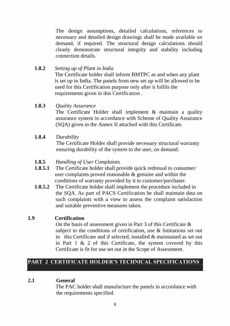
(ix) Concrete having grade M25 shall be placed and vibrated
adequately, integrating waterproofing for correct execution.
(See Fig. 4)
Fig. 4 Foundation Details
2.4.1.4 Existing foundation
When a foundation already exists or when something is being
constructed over existing construction, steps as given below shall be
followed:
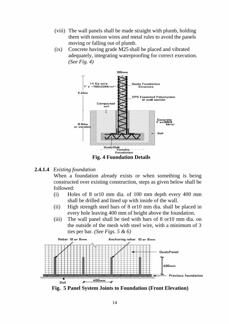
(i) Holes of 8 or10 mm dia. of 100 mm depth every 400 mm
shall be drilled and lined up with inside of the wall.
(ii) High strength steel bars of 8 or10 mm dia. shall be placed in
every hole leaving 400 mm of height above the foundation.
(iii) The wall panel shall be tied with bars of 8 or10 mm dia. on
the outside of the mesh with steel wire, with a minimum of 3
ties per bar. (See Figs. 5 & 6)
Fig. 5 Panel System Joints to Foundation (Front Elevation)
15
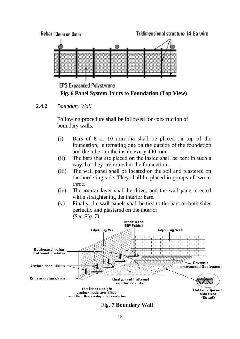
Fig. 6 Panel System Joints to Foundation (Top View)
2.4.2 Boundary Wall
Following procedure shall be followed for construction of
boundary walls:
(i) Bars of 8 or 10 mm dia shall be placed on top of the
foundation, alternating one on the outside of the foundation
and the other on the inside every 400 mm.
(ii) The bars that are placed on the inside shall be bent in such a
way that they are rooted in the foundation.
(iii) The wall panel shall be located on the soil and plastered on
the bordering side. They shall be placed in groups of two or
three.
(iv) The mortar layer shall be dried, and the wall panel erected
while straightening the interior bars.
(v) Finally, the wall panels shall be tied to the bars on both sides
perfectly and plastered on the interior.
(See Fig. 7)
Fig. 7 Boundary Wall

16
2.4.3 Wall Panels
Exterior wall panels shall be set with a minimum 6 mm (1/4 inch)
clearance between the concrete slab edge and the panel
reinforcement. The slab shall be attached with perimeter foundation
with 63 mm-long by 3 mm ( 2 ½ inch by 1/8 inch) thick steel hold-
down connector channels and 13 mm (1/2 inch) diameter
foundation bolts placed at a distance of 1.22 m (4 feet) max.
centers along width and at each panel end. Panel reinforcement and
connector channels shall be attached with 305 mm (1 feet) long, 12
gauge wires extending approximately 45 degrees upward along
each panel face from each channel end. The upper end of the
diagonal wires shall be attached to the panel reinforcement. As an
alternate, shear receivers consisting of 54 mm (2 1/8 inch) long
channel-shaped 16 gauge (1.63 mm) sheet metal fastened with two
Hartco clips each side and anchored with 13 mm-diameter anchor
bolts shall be used with the placement as above. These shear
receivers shall also be used at panel tops and openings. For details
of the shear receiver and anchor connection. (See Figs 5 and 16).
Resistance to uplift or overturning forces shall be provided by
installing a hold-down device using No. 8 gauge wire loops (See
Fig. 18). 26 gauge (0.46 mm) galvanized sheet metal flashing with
external and internal lips shall be placed between the floor slab and
wall. Vertical foam core edges of exterior wall panels shall be
treated with a 6 mm to 10 mm (¼ inch to 3/8 inch) continuous bead
of elastomeric sealant prior to butting with adjacent panel cores.
Panels shall be joined along vertical edges with 203mm (8 inch)
wide strips of 14 gauge (2.03 mm) 51 square mm (2 inch square)
welded wire mesh on each face centered on the panel joint. The
mesh shall be attached to the vertical panel wire reinforcement with
Hartco clips spaced 305 mm on center at the edge wires and 610
mm (2 feet) on center at interior wire (See Figure 12). Panels shall
also be joined on both sides with 14 gauge (2.03 mm) wire trusses
(See Fig. 17). In addition to the above, butting panel edge wires
shall be attached with the clips spaced at 610 mm on center on each
panel face. Corner and intersecting walls shall be connected with
mesh trusses and clips in a similar manner. Clips installed in
accordance with figures when truss strips shall be used as joint
mesh.
Interior wall panels shall be set and attached to hold-down
connector channels with 12 gauge (2.64 mm) wires in the same
manner as exterior panels. Approved powder-actuated anchors
shall be used, provided they are adequate for applicable uplift

17
loads. A nonstructural plaster ground shall be attached at the base
of the interior panels if desired.
Lintel sections over openings shall consist of panel sections with
truss reinforcement placed horizontally and reinforced (See Figs 15
and 20). Allowable loads shall be as per in Table 1.
Electrical raceways, switch boxes and outlet boxes shall be
installed prior to application of the cement plaster in accordance
with local requirements. Outlet boxes shall be placed to minimize
the cutting of the wire mesh reinforcement. Where two or more
wires in the same direction are cut, they must be replaced with wire
of the same gauge and attached with at least two Hartco clips at
each end at a sufficient distance beyond the opening to develop
continuity.
Plumbing and waste lines shall be limited to extending at right
angles through the wall panels and located to minimize the cutting
of panel wires.
Detail of a Wall panel is shown in Fig. 8 below:
Fig. 8 Wall Panel
2.4.4 Roof and Floor Panels
The panels shall not be permitted to bear on wood-frame walls. The
connection method of the roof panels to wall panels (See Figs 4
and 13) and the allowable loads for the connection are shown in
Table 2. Horizontal diaphragms shall be permitted the same shear
values as vertical racking shear, provided the panels are fastened to
each other and to walls as described in this report.

18
The details of a Roof panel is shown in Fig. 9 below:
Fig. 9 Roof Panel
Process flow chart is given at Annex I.
Table 1 Allowable Roof, Floor and Wall Panel Loads1
Type of
loading
Panel height
or span4 (m)
Load Remarks
kg/m kg/m2
Axial2 2.44 46075
--
--
3.66 40135
Axial3 2.44 4013
Transverse2
for wall, roof
or floor panels
1.22
--
434 Wind or lateral load applied
perpendicular to the face of
panel. For superimposed
roof or floor loads, no
increase for duration of load
is permitted.
1.52 385
1.83 273
2.13 249
2.44 195
3.05 122
3.66 78
4.27 59
Transverse3
for wall, roof
or floor panels
2.44
--
112 Wind or lateral load applied
perpendicular to the face of
panel. 3.05 & 3.66 m high
panels to be used for interior
walls only.
3.05 63
3.66 49
Racking
shear2 for wall
panels
H/D = 0.457
or less
490
-- In continuous panel runs,
12.7 mm dia anchor bolts
shall be reqd. at each end
and at a max. of 1.22 m
centers at intermediate
locations. Where panel runs
a max. of 1.22 m wide, the
anchor bolts shall be placed
at each end of the panel.
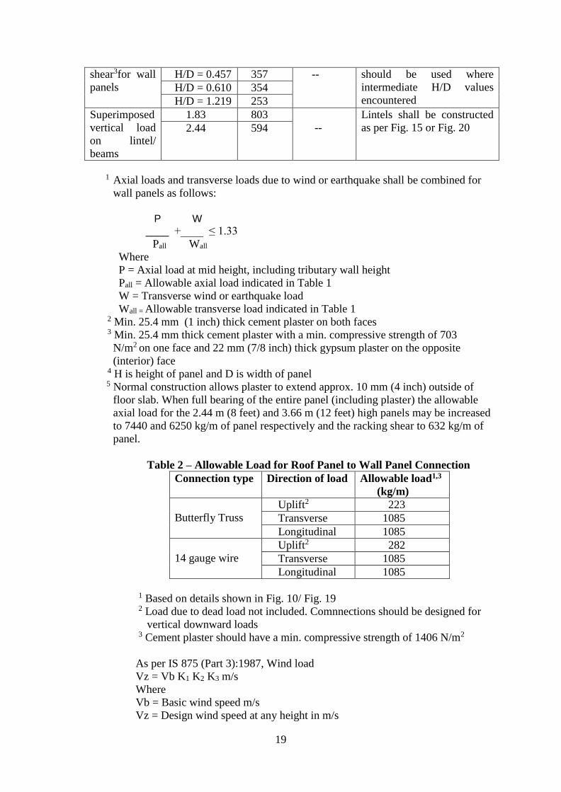
Racking H/D = 0.305 409 The lower shear values
19
shear3for wall
panels
H/D = 0.457 357 -- should be used where
intermediate H/D values
encountered H/D = 0.610 354
H/D = 1.219 253
Superimposed
vertical load
on lintel/
beams
1.83 803
--
Lintels shall be constructed
as per Fig. 15 or Fig. 20 2.44 594
1 Axial loads and transverse loads due to wind or earthquake shall be combined for
wall panels as follows:
P W
____ +____ ≤ 1.33
Pall Wall
Where
P = Axial load at mid height, including tributary wall height
Pall = Allowable axial load indicated in Table 1
W = Transverse wind or earthquake load
Wall = Allowable transverse load indicated in Table 1
2 Min. 25.4 mm (1 inch) thick cement plaster on both faces
3 Min. 25.4 mm thick cement plaster with a min. compressive strength of 703
N/m2 on one face and 22 mm (7/8 inch) thick gypsum plaster on the opposite
(interior) face
4 H is height of panel and D is width of panel
5 Normal construction allows plaster to extend approx. 10 mm (4 inch) outside of
floor slab. When full bearing of the entire panel (including plaster) the allowable
axial load for the 2.44 m (8 feet) and 3.66 m (12 feet) high panels may be increased
to 7440 and 6250 kg/m of panel respectively and the racking shear to 632 kg/m of
panel.
Table 2 – Allowable Load for Roof Panel to Wall Panel Connection
Connection type Direction of load Allowable load1,3
(kg/m)
Butterfly Truss
Uplift2 223
Transverse 1085
Longitudinal 1085
14 gauge wire
Uplift2 282
Transverse 1085
Longitudinal 1085
1 Based on details shown in Fig. 10/ Fig. 19
2 Load due to dead load not included. Comnnections should be designed for
vertical downward loads
3 Cement plaster should have a min. compressive strength of 1406 N/m2
As per IS 875 (Part 3):1987, Wind load
Vz = Vb K1 K2 K3 m/s
Where
Vb = Basic wind speed m/s
Vz = Design wind speed at any height in m/s

20
K1 = Probability factor (Risk coefficient)
K2 = Terrain height & structure size factor
K3 = Topography factor
Design wind pressure Pz = 0.6 V2z N/m2
Fig. 10 Typical Overhang Detail
Fig. 11 Panel Shear Connector Fig. 12 Wall Panel Joint
Fig. 13 Ledger Bolts to Panel Fig. 14 Butterfly Truss Strip

21
Fig. 15
Fig. 16 Shear Receiver Fig. 17 Truss Strip Connection at Wall Joint
Fig. 18 Hold-down Anchor Fig. 19 Typical Eave Detail

22
Fig. 20 Typical Door Opening Reinforcement
2.4.5 Installation of Panels
The procedure for installing the panels shall be as follows:
1. The panels shall be put in place according to the building plan
as follows:
It must be ensured that the rebar is on the bottom of the
panel
Each panel shall have a portion of wire mesh on the end
without polystyrene.
The adjacent panel shall be inserted into this area thereby
locking them together. The overlapping wire mesh should
be tied together.
The vertical rebar in the wall shall be allowed to go
through the polystyrene in the panels.
It shall be necessary to cut some of the wire mesh to
allow this. The rebar on the bottom of the panel shall not
be cut.
2. The polystyrene in the areas directly over the walls shall be
removed.
3. The rebar that bends into the panels shall be placed according to
the wall reinforcement and this bar shall be tied to the wire

23
mesh on top of the panel. The vertical rebar shall be extended as
necessary.
4. The support props shall be placed beneath the panels as follows:
The panels should be supported from below at a spacing
of max. 1 m in each direction.
Wood beams shall be placed between the panels and the
props in the direction opposite the rebar on the bottom of
the panel.
The middle prop shall be higher than the others as per the
building plan. (See Fig. 21)
5. The edge molds shall be placed around the perimeter of the
panel as follows:
Each set of holes in the edge molds shall be tied tightly to
the panel
It must be ensured that the edge molds are level and
straight.
It must also be ensured that there is more than 50 mm
clearance between the top of panels and top of edge
molds.
6. A minimum M20 grade of concrete shall be used.
7. The concrete shall be placed in 50 mm thick layer on top of the
panels. It must be ensured that there is a smooth and level
surface by using the bubble level.
8. The edge molds shall be removed after 24 hours while the props
after 7 days.
9. The surface of the concrete should be kept moist for 28 days
and the concrete shall not be allowed to become dry during this
period.
Fig. 21 Counter Shaft

24
Table 3 Slab Camber at Panel Midspan
Slab clearance (m) 3 4 5
Camber (mm) 30 35 40
2.4.6 Supports and Cambers
Slabs for roofs and floors shall be made with slab panels and
supported during erection with temporary beams with props spaced
at 900 mm, leaving a camber (see table below). The support beams
shall be located on the bottom of the panel, always perpendicular to
the direction of the zigzag trusses in the panel. Most of the supports
shall be removed 14 days after concreting, leaving only those
supporting the center of the span for 30 days.
Table 4 Cambers for Floor and Roof
Slab span (m) 2.50 3.25 4.06 4.50 5.00
Slab simply supported
on both ends (mm)
10 30 35 35 40
Continuous slab or
slab supported on 3 or
more ends (mm)
10
15
20
25
30
2.4.7 Connections
All the connections for walls and slabs shall use the self-connection
system, where the mesh on the end of the panel shall be used to join
the panels in different situations. (See Fig. 22)

25
Fig. 22 Connections
2.4.8 Door and Window
These shall be made by marking and cutting the mesh of the wall
panel with a circular saw, reciprocating saw, or with wire cutters,
and reinforcing the edges on both sides with zigzag mesh. The
zigzag mesh should extend 300 mm from the edges of the doors
and windows. Afterwards, diagonal zigzag mesh shall be installed
on every corner of 400 mm.
Where edges and corners are reinforced, the polystyrene along the
perimeter of the opening shall be removed and the space is filled
with mortar or concrete to form a rigid boundary. In the area on top
of the opening, the polystyrene shall be removed and reinforcing
steel placed to form a lintel beam. (See Figs. 23 & 24)
Fig. 23 Door and Window Connection Details

26
Fig. 24 Door and Window Nozzles (Elevation)
2.4.9 Plumbing and Electrical Fixtures
Water pipes and electrical conduits shall be placed within the
panels as shown in the building plans. The guidelines for installing
pipes and conduits in the panels shall be as follows:
Polystyrene in the panel shall be removed to
accommodate pipe and conduits
Large pipes shall require cutting wire mesh so as to fit in
the panel. The wire mesh on top of the panel shall only be
cut.
The pipe should not be higher than 25 mm above wire
mesh on top of the panel.
Taps, other plumbing fixtures and electrical fittings
should be fixed after plastering
Taps shall be located at floor height other than the sill
level. The vertical pipes shall be fixed along the wall
surface to provide the taps at the levels above the finished
floor level – for toilets at 450 mm, for bathrooms at 750
mm and for kitchen at 900 mm.
All floor drains should be provided with perforated
covers.
Wires to electrical wall fittings should be fixed from the
ceiling panel to the location indicated on the building
plans and conduit installed on the wall surface.
Wall electrical fittings should be located at 1200 mm
above the finished floor level. (See Figs 25 & 26)

27
Fig. 25 Duct Work on Panel System (Top View)
Fig. 26 Installation of Duct Work
2.4.10 Plumb and Alignment
It shall be assured that the wall panel is plumb and in line,
and to maintain right angles between them, tension wire and
metal rulers shall be used. (See Figs. 27 & 28)

28
Fig. 27 Plumb and Align – Cross section Panel System
The polystyrene in the center of the panel shall be toothed on the
surface to ensure better mortar connection and less wastage.
Fig. 28 Plumb and Align (Schematic drawing)
2.4.11 Finishing
2.4.11.1 Floor finishing
The guidelines for floor finish shall be as follows:

29
It must be ensured that the floor area is completely clear
of any debris, dust and soil etc.
It must be ensured that the floor surface is damp prior to
finishing and it should be fully moist without any water
stagnating on it.
Cement mortar of mix 1 cement: 3 sand shall be prepared
and required quantity of mortar shall be applied to the
floor to provide a smooth finish.
Slope shall be given in the floor as per the building plans.
However, if no slope is specified, minimum slope
towards the doorway out of the room shall be provided.
Floor finish should be allowed to be cured for at least 10
days after placement.
2.4.11.2 Ceiling finishing
The guidelines for ceiling finish shall be as follows:
A stiff mix of 1 cement: 3 sand mortar shall be prepared
and applied to the ceiling, providing a level but rough
surface. This layer should be cured for at least 24 hours
before next layer is applied.
It must be ensured that the first layer of plaster is damp
prior to applying the finish layer.
Cement mortar of mix 1 cement: 4 sand shall be prepared
and required quantity of mortar shall be applied to the
ceiling to provide a smooth finish.
The total thickness of the ceiling finish should not exceed
19 mm below the panel wire mesh.
Ceiling finish should be allowed to be cured for at least 10
days after placement.
2.4.11.3 Wall finishing
The guidelines for wall finish shall be as follows:
It must be ensured that the wall is damp prior to applying
plaster.
Cement mortar of mix 1 cement: 4 sand shall be prepared
and 25 mm plaster shall be applied to the wall to give a
finish surface.
Wall plaster should be allowed to be cured for at least 7
days after placement. (See Fig. 29)

30
Fig, 29 Panel System Wall (Schematic Drawing)
2.4.12 Handling of Panels
These panels are composed of two layers of steel wire mesh with a
layer of polystyrene in the middle. The bottom side of each panel
has rebar welded in which provides the strength that allows the
panel to be used as a slab. The wire mesh on the top and bottom are
connected to each other with a ‘zig-zag truss’ of wire running
between the two meshes, welded at each joint.
The guidelines for handling the panels for ensuring safety shall be
as follows:
Gloves shall always be worn while handling the panels
otherwise the hands may be cut with the ends of the wire
mesh
The wire mesh or rebar shall not be bend, deform or broken,
except necessary to cut or install the panels.
2.4.13 Cutting of Panels
As the panels are manufactured in a few fixed sizes, it shall be
necessary to cut the panels to a smaller size. The procedure for
cutting of the panels shall be as follows:
The length of the panel to be cut shall be measured and the
measurement extended to the far-side of the nearest cross-
wire. This measurement extension shall make the panel size
longer and not smaller.

31
Bolt cutters shall be used to cut the wires along the measured
length on one side of the panel.
Panels shall be flipped to the other side and bolt cutters used
to cut the wires along the measured length on the other side
of the panel.
Panels shall be allowed to stand on its end and bended to 90
to expose the ‘zig-zag truss’. The bolt cutter shall be used to
cut the exposed wires.
It shall be necessary to bend the panel to 90º in the other
direction also to expose the rest of the ‘zig-zag truss’ wires
and cut them with bolt cutters.
2.5 Transportation, Handling and Storage of Panels
2.5.1 Transportation
The panels shall be shipped using closed body containers on
all sea routes.
On land route, open body trailers may be used to transport
more materials.
In case of open body container, the panels shall be strapped
or tied up in an appropriate manner for withstanding the wind
and travel velocity.
Flammable materials should not be stacked along with the
panels.
2.5.2 Handling
Panels shall be stacked in an appropriate manner to prevent
sliding, spreading, or falling.
Panels shall be stacked one on one basis with the longest
panel at the bottom / side.
Lagging (sleeve) shall be used when steel is handled by a
crane or forklift to aid safe rigging.
Gloves shall be used while loading or unloading manually.
The top panel shall be removed from a stack on top of the
stock.
2.5.3 Storage
Panels shall be stored in a planned and orderly manner that
does not endanger employee safety.
It must be ensured that stacks are stable and stacked to aid
safe handling and loading.
Panels shall be stored on pallets to discourage rodent.

32
Spills and leaks from rodents shall immediately be cleaned
up.
Petrochemical products or flammable products shall not be
stored near the panels.
2.5.3.1 Storing panels in an open yard
Combustible materials should be stored at least 5 meters
away from a building or structure.
Stacks shall not be more than 5 meter high.
Panels shall be covered with high density polythene sheets.
Driveways between and around panels shall be at least 3
meter wide.
The stacks shall be kept free from accumulations of material
or rubbish.
A map grid system shall be used for planning driveways in
open-yard.
Panels shall not be stored under power lines or where they
may block egress or emergency equipment.
Portable fire extinguishing equipment shall be provided at
accessible marked locations in the yard so that the nearest
extinguisher is not more than 15 meter away from the panel.
2.5.3.2 Storing panels indoors
In order to store panels indoors, special attention shall be
required to access, fire prevention and protection, floor
loading and overhead hazards.
Panels shall be placed so they do not interfere with access
ways, doorways, electrical panels, fire extinguishers etc.
The access ways or exits shall not be obstructed with
accumulations of scrap near Panels.
Aisles should be wide enough to accommodate forklifts or
firefighting equipment.
Portable fire extinguishing equipment shall be provided at
accessible marked locations in the yard so that the nearest
extinguisher is not more than 15 meter away from the panel.
Panels shall be placed inside buildings under construction at
least 2 meter away from any hoist way or inside floor
openings, and 3.50 meter away from an exterior wall that
does not extend above the top of the material stored.
33
2.6 Inspections & Testing
Inspections & testing shall be done at appropriate stages of
manufacturing process of all the components. The inspected frames
and panels shall be stored & packed to ensure that no damage
occurs during transportation. As part of quality assurance, regular
in process inspections shall be carried out by the trained personnel
of the PAC holder.
2.7 Good Practices for Installation & Maintenance Good practice as per requirement including Do’s & Don’ts of
working with Rapid panel System of the manufacturer shall be
followed for erection and maintenance of these sections.
2.8 Maintenance Requirements
It is assumed that no special maintenance is required during
intended working life. Should repairs prove necessary, it shall ably
be carried out by the trained persons using appropriate products
and materials.
2.9 Skilled /Training Needed for Installation
Special training shall be required to get necessary skill set for
assembly of Rapid panels and their erection. Moreover, workers
shall be trained/ oriented on handling and installation of modules,
panels etc. and support system with all required safety measures
taken including heavy hats, protective shoes etc.
2.10 Guarantees/Warranties Provided by the PAC Holder
PAC holder shall provide necessary guarantees/ warranties of the
system to the client.
2.11 Responsibility
Specific design using Rapid panels technology is the
responsibility of the designer with the instructions, supervision
and guidance of the PAC holder.
Quality of installation/construction of the system on site is the
responsibility of the trade persons engaged by the
manufacturer.
Quality of maintenance of the building is the responsibility of
the building owner.
Providing necessary facilities and space for movement of
cranes and vehicles is the responsibility of the manufacturer.

34
PART 3 BASIS OF ASSESSMENT AND BRIEF DESCRIPTION OF
ASSESSMENT PROCEDURE
3.1 Assessment
3.1.1 The technical assessment was done as per provisions of the
Standards listed in Part 5 of this Certificate.
3.2 Site Inspection Inspection of a complete module assembled at site for construction
of a house (G+1) of 110 sqm area approx. by the manufacturer was
done by the TAC members and IOs. A (G+2) flat of 60 sqm area
approx. constructed in 2015 was also inspected by the TAC
members and IOs. The work was found to be satisfactory and the
occupants have no complaints.
3.3 Tests Performed
3.3.1 By Civil-Aid Technoclinic Pvt. Ltd., Bangalore
1. Test Report on Galvanised high strength steel bars in January, 2016
i. Measured dia (mm) : 1.90, 2.65
ii. UTS (N/mm2) : 687 632
iii. Elongation (%) : 4.8 6.1
2. Test Report on Wall Panel in February 2014
The following tests were conducted on the sample of wall panel:
i. Axial Load test
ii. Rebound Hammer test
iii. Nail withdrawal test
i. Result of Axial Load test
Dimensions of Sample: 3100 mm x 1220 mm x 115 mm
Maximum load applied: 12.0 tons
Maximum deflection: 5.50 mm
Table 5 Load applied (ton) Central deflection
measured (mm)
Observation
0 0 The wall panel is capable of
taking the min. load of 12.0 ton
No crack observed on the
surface of the wall panel
5.0 2.7
10.0 5.0
12.0 5.5
35
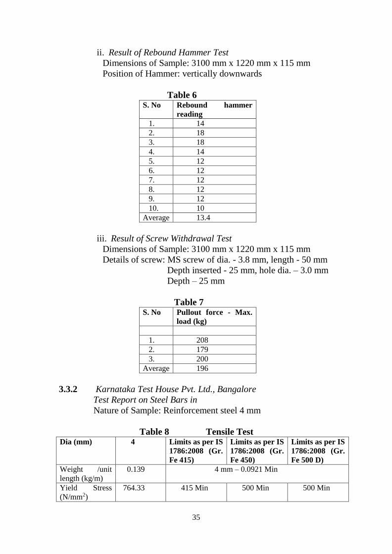
ii. Result of Rebound Hammer Test
Dimensions of Sample: 3100 mm x 1220 mm x 115 mm
Position of Hammer: vertically downwards
Table 6 S. No Rebound hammer
reading
1. 14
2. 18
3. 18
4. 14
5. 12
6. 12
7. 12
8. 12
9. 12
10. 10
Average 13.4
iii. Result of Screw Withdrawal Test
Dimensions of Sample: 3100 mm x 1220 mm x 115 mm
Details of screw: MS screw of dia. - 3.8 mm, length - 50 mm
Depth inserted - 25 mm, hole dia. – 3.0 mm
Depth – 25 mm
Table 7 S. No Pullout force - Max.
load (kg)
1. 208
2. 179
3. 200
Average 196
3.3.2 Karnataka Test House Pvt. Ltd., Bangalore
Test Report on Steel Bars in
Nature of Sample: Reinforcement steel 4 mm
Table 8 Tensile Test Dia (mm) 4 Limits as per IS
1786:2008 (Gr.
Fe 415)
Limits as per IS
1786:2008 (Gr.
Fe 450)
Limits as per IS
1786:2008 (Gr.
Fe 500 D)
Weight /unit
length (kg/m)
0.139 4 mm – 0.0921 Min
Yield Stress
(N/mm2)
764.33 415 Min 500 Min 500 Min

36
Tensile Strength
(N/mm2)
907.64 10% more than
actual 0.2%
proof stress but
not less than 485
N/mm2
8% more than
actual 0.2%
proof stress but
not less than 545
N/mm2
10% more than
actual 0.2%
proof stress but
not less than 565
N/mm2
Elongation (%) 16.0 14.5 Min 12.0 Min 16.0 Min
3.3.3 By M/s Shriram Institute for Industrial Research, Delhi
Test Report on EPS in January, 2016
i. Bead size (%) : 96
ii. Environmental Hazardous substances :
a. Lead content as Pb, (ppm) : < 1
b. Cadmium content as Cd (ppm) : < 1
c. Mercury content as Hg (ppm) : < 0.01
d. Hexavalent chromium content as Cr +6 (ppm): <1
3.3.4 By IIT Madras, Chennai in November, 2012
Load tests on prefabricated sandwich roof panels:
Single-point loadings (shear) and two point load (bending).
Based on static tests under gravity loading, IIT Madras has certified
that RapidPanel Roofing slab system is found satisfactory for use
in buildings, for imposed loads (live loads) defined in IS 875 (Part
2):1987, under the following conditions:
1. Panel lengths up to 5.01 m, with appropriate camber provided,
simply supported on beams or bearing walls not less than 125
mm in width
2. Panels installed with M20 grade of concrete and 1:3 cement
mortar
3. Total dead load (including panel self-weight) not to exceed 3.3
kN/m2
4. Total imposed load (live load) not to exceed 3.0 kN/m2
3.4 Execution of Projects
The manufacturer, as reported, has constructed the buildings as per
the details given below: (These have not been inspected by
BMTPC)
S. No. Name & location of the
project
Total Area
(sqm)approx.
Period of
Completion
1. Construction of Ground
floor house at Sarjapura,
200 June 2014

37
Bangalore
2. Construction of Basement
+ Ground floor house at
Coorg, Bangalore
300 July 2014
3. Construction of S+2,
Nirmithi Kendra at
Bangalore
120 July 2014
4. Construction of S+2+H
floor flat at Bangalore
180 October
2014
5. Construction of S+2 floor
flat at Bangalore
120 January
2015
6. Construction of CSI
Church at Hosur,
Bangalore
350 May 2015
7. Construction of G+2 floor
flat at Bangalore
120 May 2015
8. Construction of G+3 flat at
Bhubaneswar
200 November
2015

38
This certificate holder shall satisfy the following conditions:
4.1 The certificate holder shall continue to have the product reviewed by BMBA.
4.2 The product shall be continued to be manufactured according to and in
compliance with the manufacturing specifications and quality assurance
measures which applied at the time of issue or revalidation of this certificate. The
Scheme of Quality Assurance separately approved shall be followed.
4.3 The quality of the product shall be maintained by the certificate holder. Complete
testing facilities shall be installed for in-process control.
4.4 The product user should install, use and maintain the product in accordance with
the provisions in this Certificate.
4.5 This certificate does not cover uses of the product outside the scope of this
appraisal.
4.6 The product is appraised against performance provisions contained in the
standards listed in Part-V. Provisions of any subsequent revisions or provisions
introduced after the date of the certificate do not apply.
4.7 Where reference is made in this Certificate to any Act of Parliament of India,
Rules and Regulations made there under, statutes, specifications, codes of
practice, standards etc. of the Bureau of Indian Standards or any other national
standards body and the International Organization for Standardization (ISO),
manufacturer’s company standards, instruction/manual etc., it shall be construed
as reference to such publications in the form in which they were in force on the
date of grant of this Certificate (and indicated in Part V to this Certificate)
4.8 The certificate holder agrees to inform BMBA of their clients with details of
construction on six monthly basis.
4.9 The certificate holder agrees to provide to BMBA feedback on the complaints
received, the redressal provided, and the time taken to provide redressal on
complaint to complaint basis as soon as redressal is provided. BMBA agrees to
provide the certificate holder the user feedback received by it, if any.
4.10 If at any time during the validity period, PACH is unable to fulfill the
conditions in his PAC, he should on his own initiative suspend using the PAC
and notify Chairman, PAC the date from which he has suspended its use, the
reason for suspension and the period by which he will be able to resume. He
shall not resume without the prior permission of BMBA. He shall also inform,
simultaneously, his agents, licensees, distributors, institutional, government,
public sector buyers, other buyers and all those whom he has informed about
his holding the PAC. He shall also inform all those who buy his product(s)
during the period of suspension. He shall provide to BMBA at the earliest the
list of who have been so informed by him.
PART 4 STANDARD CONDITIONS
40
PART 5 LIST OF STANDARDS & CODES USED IN ASSESSMENT
5.1 Standards - These Standards are referred for carrying out particular tests
only and do not specify the requirement for the whole product as such.
5.1.1 IS 383:2016 – Specifications for fine and coarse aggregates from natural
resouces
5.1.2 IS 456:2000 -- Code of practice for plain and reinforced concrete
5.1.3 IS 875 (Part 1):1987 -- Code of Practice for Design Loads (Other
Than Earthquake) for Buildings & Structures Part 1 Dead Loads - Unit Weights
of Building Material & Stored Materials (Incorporating IS 1911: 1967)
5.1.4 IS 875 (Part 2):1987 -- Imposed Loads
5.1.5 IS 1346:1991 – Code of practice for waterproofing of roofs
5.1.6 IS 1542:1992 – Specifications for sand for plaster
5.1.7 1786:2008 – Specifications for high strength deformed steel bars and
wires for concrete reinforcement
5.1.8 IS 1893 (Part 1):2002 -- Criteria for Earthquake Resistant Design of
Structure
5.1.9 IS 1904: 2005 – Code of practice for design and construction of
foundations in soils: General requirements
5.1.10 IS 2095 (Part 1):2011 – Specifications for gypsum plaster board
5.1.11 IS 2645:2003 – Specifications for integral water proofing compounds for
cement, mortar and concrete
5.1.12 IS 4326:1993 -- Code of Practice for Earthquake Resistant Design and
Construction of Buildings
5.1.13 IS 4671:1984 -- Specifications for expanded polystyrene for thermal
insulation purposes
5.1.14 IS 8112:2013 – Specifications for 43 grade ordinary portland cement
5.1.15 IS 9103:1999 -- Specifications for concrete admixtures
5.1.16 ASTM A 307-14 – Standard specifications for carbon steel bolts and
studs
5.1.17 ASTM C 881 -- Standard specifications for epoxy resin based bonding
5.1.18 EN 14889-2:2006 -- Standard specifications for plymers for concrete
Part 5.2 Company Standards of the PAC holder – The branded design &
specifications of the raw materials and finished product are as submitted by the
manufacturer. The PAC holder has to make available the company standards to
the consumers according to which testing have been done.

42
PART 6 ABBREVIATIONS
Abbreviations
BMBA Board of Agreement of BMTPC
BMTPC Building Materials and Technology Promotion
Council
CPWD Central Public Works Department
ED Executive Director of BMTPC
IO Inspecting Officer
MS Member Secretary of BBA
PAC Performance Appraisal Certificate
PACH PAC Holder
PACS Performance Appraisal Certification Scheme
SQA Scheme of Quality Assurance
TAC Technical Assessment Committee (of BMBA)

43
PERFORMANCE APPRAISAL CERTIFICATION SCHEME - A BRIEF
Building Materials & Technology Promotion Council (BMTPC) was set up by the
Government of India as a body under the Ministry of Housing &Urban Poverty
Alleviation to serve as an apex body to provide inter-disciplinary platform to promote
development and use of innovative building materials and technologies laying special
emphasis on sustainable growth, environmental friendliness and protection, use of
industrial, agricultural, mining and mineral wastes, cost saving, energy saving etc.
without diminishing needs of safety, durability and comfort to the occupants of
buildings using newly developed materials and technologies.
During the years government, public and private sector organizations independently or
under the aegis of BMTPC have developed several new materials and technologies.
With liberalization of the economy several such materials and technologies are being
imported.
However, benefits of such developments have not been realized in full measure as
understandably the ultimate users are reluctant to put them to full use for want of
information and data to enable them to make informed choice.
In order to help the user in this regard and derive the envisaged social and economic
benefits the Ministry of Housing &Urban Poverty Alleviation has instituted a scheme
called Performance Appraisal Certification Scheme (PACS) under which a
Performance Appraisal Certificate (PAC) is issued covering new materials and
technologies. PAC provides after due investigation, tests and assessments, amongst
other things information to the user to make informed choice.
To make the PACS transparent and authentic it is administered through a Technical
Assessment Committee
(TAC) and the BMTPC Board of Agreement (BMBA) in which scientific,
technological, academic, professional organizations and industry interests are
represented.
The Government of India has vested the authority for the operation of the Scheme
with BMTPC through Gazette Notification No. 1-16011/5/99 H-II in the Gazette of
India No. 49 dated 4th December, 1999.
Builders and construction agencies in the Government, public and private sectors can
help serve the economic, development and environmental causes for which the people
and Government stand committed by giving preference to materials and technologies
which have earned Performance Appraisal Certificates.
Further information on PACS can be obtained from the website: www.bmtpc.org

44
ANNEX I
(Clause 1.3.2)
Production Flow Chart
45
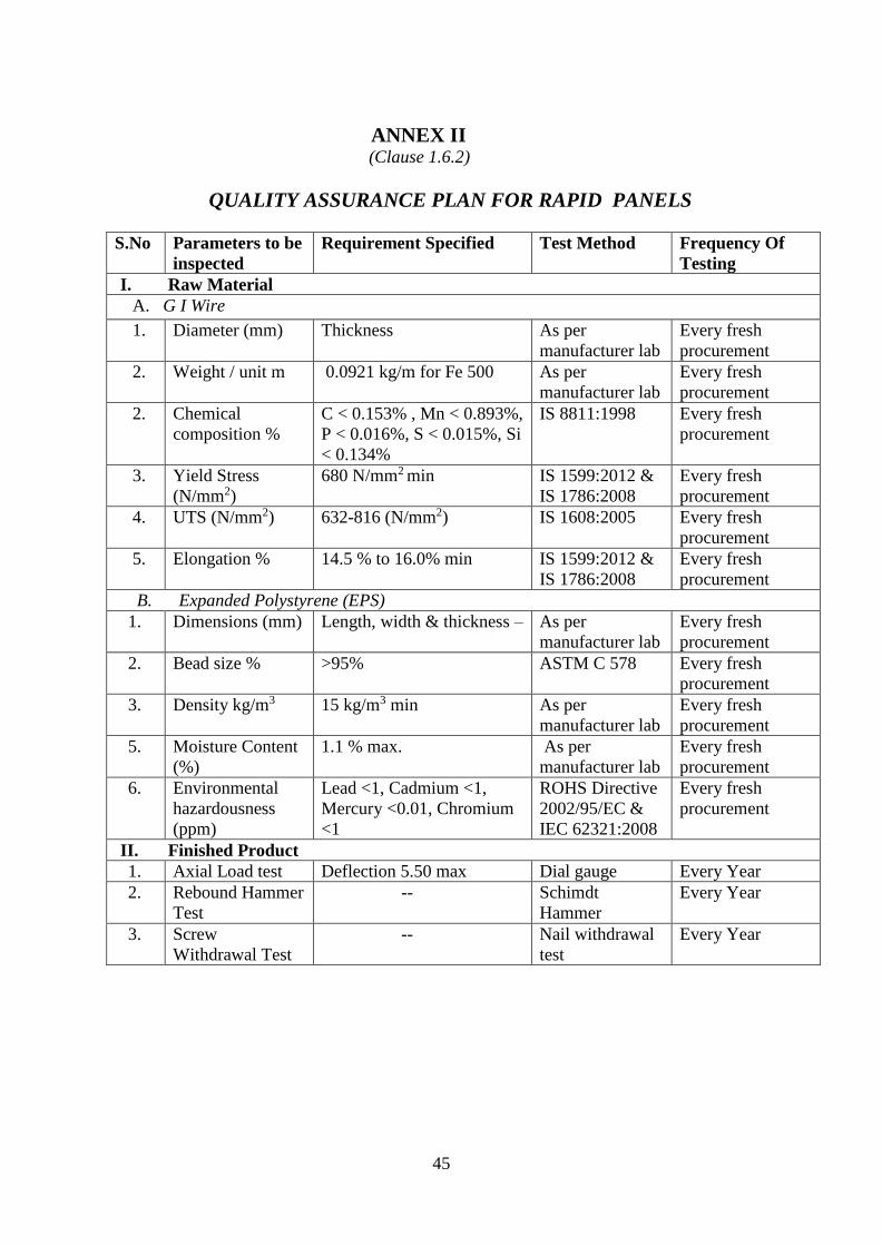
ANNEX II
(Clause 1.6.2)
QUALITY ASSURANCE PLAN FOR RAPID PANELS
S.No Parameters to be
inspected
Requirement Specified Test Method Frequency Of
Testing
I. Raw Material
A. G I Wire
1. Diameter (mm) Thickness
As per
manufacturer lab
Every fresh
procurement
2. Weight / unit m 0.0921 kg/m for Fe 500 As per
manufacturer lab
Every fresh
procurement
2. Chemical
composition %
C < 0.153% , Mn < 0.893%,
P < 0.016%, S < 0.015%, Si
< 0.134%
IS 8811:1998 Every fresh
procurement
3. Yield Stress
(N/mm2)
680 N/mm2 min
IS 1599:2012 &
IS 1786:2008
Every fresh
procurement
4. UTS (N/mm2) 632-816 (N/mm2) IS 1608:2005 Every fresh
procurement
5. Elongation % 14.5 % to 16.0% min IS 1599:2012 &
IS 1786:2008
Every fresh
procurement
B. Expanded Polystyrene (EPS)
1. Dimensions (mm) Length, width & thickness – As per
manufacturer lab
Every fresh
procurement
2. Bead size % >95% ASTM C 578 Every fresh
procurement
3. Density kg/m3 15 kg/m3 min As per
manufacturer lab
Every fresh
procurement
5. Moisture Content
(%)
1.1 % max. As per
manufacturer lab
Every fresh
procurement
6. Environmental
hazardousness
(ppm)
Lead <1, Cadmium <1,
Mercury <0.01, Chromium
<1
ROHS Directive
2002/95/EC &
IEC 62321:2008
Every fresh
procurement
II. Finished Product
1. Axial Load test Deflection 5.50 max Dial gauge Every Year
2. Rebound Hammer
Test
-- Schimdt
Hammer
Every Year
3. Screw
Withdrawal Test
-- Nail withdrawal
test
Every Year

46
ANNEX III (Clause 2.3)
Production Stages
The production stages as reported are given below:
1. Raw Material
The steel wires/ rods and EPS of specified quality shall be procured
as per quantity required and stored at the stock yard.
2. Truss
The truss machine produces two trusses simultaneously, with
length and width programmed by the operator. The steel wire shall
be staged on spools and fed into the first machine, which shall
straightens six lines of spooled wire. The straightened wires shall
feed directly into the truss machine. The center wire on each of the
two tracks shall be bent into the zig-zag shape.
The two outer wires on each track shall be drawn parallel to the
zig-zag
And welded to its corners. Once the programmed length of truss is
produced, the operator places the trusses on a storage rack. The
equipment itself does not require any direct operation after it has
been programmed, except to start and stop the process.
3. Assembling Trusses and EPS Strips
A movable rack specially designed to feed through the panel
machine shall be used to assemble the panel and prepare it for
welding to the cross wires. A truss shall be placed horizontally on
the bottom of the rack, then alternating layers of EPS strips (67 mm
thick) and trusses placed until the rack is full (achieving the 1200
mm panel width). A lever shall be closed on the top of the rack to
secure the layers in place, and the positions of the EPS strips and
trusses adjusted to ensure they are in line. The rack shall then
positioned near the panel machine.
4. Panel
The rack fits into a track on the panel assembly welder, confining it
to only move though the machine. The machine operator feeds the
front of the panel into the machine, then starts the machine. The
panel automatically moves through the machine in steps of 67mm.
Steel cross wires on spools are drawn into the top of the machine
and fed onto either side of the panel, perpendicular to the trusses.

47
The machine welds each intersection of the chord wires and truss
wires at once before pushing the panel another 67 mm and doing
the same thing. This continues until the end of the panel is reached.
The operator manually starts and stops this process at the beginning
and end of the panel.
5. Manual Welding and Repair
The completed panel is moved to the hand repair station, which is a
large table with a hand welder. First, the continuous connection
feature is completed by manually welding two more wires along
the length (parallel with the truss) where the cross wires extend
beyond the EPS. Then the panel is checked for any weld points that
the panel assembly welder may have missed, and these points are
manually welded.
6. Post-Production
Completed panels are stored in a godown for use or sale.

48
ANNEX IV
(Clause 1.3)
TYPICAL DESIGN OF A BUILDING
The building has been designed for G+3 floors. All elements are designed as per
Indian Standards.
1. Design Parameters
Size of the plot: 12.20 X 12.20 mtr.
Type of Building: R.C.C Rapid panel Slab and R.C.C Rapid panel Slab
wall.
Number of storey: Ground + 3 floors.
Safe Bearing capacity of the soil as per the soil investigation report: 1.50
mtr below G.L= 20 T/m2.
Type of foundation: Isolated footing.
Grade of Concrete: M25 min. Cement content shall be as per provisions
of IS 456:2000, for moderate environmental exposure condition.
Grade of Steel (Fe 500): All reinforcement shall be high yield deformed
bars of Fe-500, indicated with a prefix # with the appropriate bar diameter
in the drawings.
Environmental exposure condition considered would be ‘moderate’.
Density of Concrete: 25 kN/m3
Density of Rapid panels: 5.5 kN/m3 ( as per test report)
2. Static Loads consideration.
All loads and combinations are as per IS 875:1987 and IS 456:2000.
2.1 Ground floor roof
Dead load of slab: Rapid panel + (75 mm floor finishing) + (25 mm ceiling
plastering).
Live load= 2.0 kN/m2 (As per Table 1, IS 875(Part 2):1987). Residential
occupancy.
Wall load: Rapid wall panel load, 5.5 kN/m3 + 35 mm cement mortar plastering
works both face of the wall.
Stair case load: Rapid panel + (75 mm staircase finishing).
2.2 First floor and second floor Dead load of slab: (Rapid panel + (75 mm floor finishing) + (25 mm ceiling
plastering).

49
Live load: 2.0 kN/m2. (As per Table 1, IS 875(Part 2):1987). Residential
occupancy.
Wall load: Rapid wall panel load, 5.5 kN/ m2+ 35 mm cement mortar plastering
works both face of the wall.
Stair case load: Rapid panel + (75 mm staircase finishing).
2.3 Third floor roof (Terrace) Dead load of slab: Rapid panel + (75 mm floor finishing) + (25 mm ceiling
plastering) + WPC.
Live load: 1.5 kN/m2 Flat roof with Access. (As per Table 1, IS 875(Part
2):1987). Residential occupancy.
Wall load: Rapid wall panel load, 5.5 kN/ m2 + 35 mm cement mortar plastering
works both face of the wall.
Stair case load: Rapid panel + (75 mm staircase finishing).
3. Seismic load.
Zone II (As per IS 1893:2002 Bangalore region falls under Zone –II. Relevant
earthquake parameters as per zone-II are considered in the design).
Importance Factor: Important Building, 1.5.
Response Reduction: Special RC Frame building, 5.0
Type of soil: medium soil
Damping: 5%.
4. Load combination.
Ultimate limit state (partial safety factors as per IS 456:2000, CI 36.4.1)
UL=1.5 (DL+LL)
UL=1.5 (DL+EQL/WL) or (0.9DL+ 1.5 EQL/WL)
UL=1.2 (DL+LL+EQL/WL)
Serviceability limit state
SL=1.0(DL+LL)
UL=1.0DL+ 0.8LL+ 0.8 EQL/WL
UL=1.2(DL +EQL/WL).
5. Foundation analysis.
All the isolated footing is analyzed as per the standard empirical methods.
Design of Panel wall and roofing/flooring system

50
Slab Panel floor
Dead Load of panel: 5.5 kg/m2 = 0.055 kN/m2
Self-weight of concrete 75 mm thick = 1.875 kN/m2
Ceiling Plaster 20 mm thick = 0.4 kN/m2
Finished Load = 0.8 kN/m2
Total Dead Load = 3.075 = 3.13 kN/m2
Wall Panel
Dead Load of panel: 5.5 kg/m2 = 0.055 kN/m2
Plastering external 35mm thick = 0.7 kN/m2
Plastering internal 35mm thick = 0.7 kN/m2
Total Dead Load = 1.455 = 1.5 kN/m2
Live Load as per IS-875 Part-2:1987 for Residential Floor = 2.0 kN/m2
Live Load as per IS-875 Part-2:1987 for Residential = 1.5 kN/m2
(Access Terrace).
*Load due to wall per running meter
Height of each floor 3.0 m (Ground floor to first floor)
3.0 m (First floor to second floor)
3.0 m (Second floor to Terrace floor)
1.0 m (Ground level to Foundation)
0.45 m (parapet wall)
Total Height = 10.45m
Wall construction
All corners and wall joints should be reinforced with right angled wire
mesh to the full height of the walls.
To cut panels to fit for door & window openings, wire should be cut with
a wire cutter or angle grinder. Measure and mark the cut lines before
starting to cut.
After the wire mesh has been cut, EPS shall be cut with a hacksaw blade
or stiff blade hand saw.
Added steel mesh reinforcement shall be required around door and
window openings to ensure that no plaster cracks form in these areas.
Mesh reinforcement strips shall be tied diagonally with wire around
openings before plastering.
Once wall panels are in place and tied together, bracing shall be required
to hold them vertical before plastering. This shall be done only on one
side of the panels.
Once the panels are plastered on one side, the wall bracing shall be
removed after 24 hours. The panels are now sufficiently stiff so that
plastering on other side can be done without bracing.

51
Extra Vertical reinforcement should be provided floor to floor junction.
Slab construction
Same as wall construction.
When connecting a slab to load bearing wall panel, the EPS within the
entire joint area should be removed and the joint should be fully
concrete. Also, additional steel wire mesh should be tied to all joints.
If panels need to extended or otherwise joined together, a full concrete
section should be provided at the joint with the same strength of the
panel itself. Note that the allowable positive moment capacity of the
panel is 23 Knm. So any full concrete joint should be designed to have
the same capacity.
Load due to wall per running meter = L x B x H x weight per cu meter
=1 m x 10.45 m x 1.5 kN/m2
= 15.7 kN
Load due to roofing per running meter load.
Area of roof per running meter = 1m x 5.5 m =5.5 m2
Floor Load for Ground roof, First roof and second roof
Dead load = 3.13 kN/m2
Live load = 2.0 kN/m2
Total dead+ live load = 5.13 kN/m2x 5.5m2 =28.2 kN per running meter.
Ground + first + second floor =3 x 25.5Kn = 84.6 kN
Roof Load for terrace
Dead load = 3.13 kN/m2
Live load = 1.5 kN/m2
Total dead + live load = 4.63 kN/m2 x 5.5 m2 =25.5 kN per running meter.
Terrace load =25.5 kN
Total Load due to roofing per running meter load =110.1 kN
Total wall panel load of all floor + total roofing load per running meter =
126 kN per running meter.

52