name 430 marine engineering sessional (lab sheet...
TRANSCRIPT

NAME 430 – Marine Engineering Sessional (Lab Sheet) Experiment – 04: Study and Performance Test of a Refrigeration Unit
Prepared by – Md. Habibur Rahman, Lecturer (Dept. of NAME), BUET 1 | P a g e
01. Name of the Experiment: Study and Performance Test of a Refrigeration Unit.
02. Write down the objectives of this experiment.
03. Specifications & Ambient Data
Model
Type of refrigerants
Power input
Compressor side maximum pressure
Suction side minimum pressure
Type of transducer used for measuring temperature
Compressor Type
Sub-cooling availability
Super heating availability
04. A system diagram of the Refrigeration unit along with its performance test set-up is shown
below - - -

Prepared by – Md. Habibur Rahman, Lecturer (Dept. of NAME), BUET 2 | P a g e
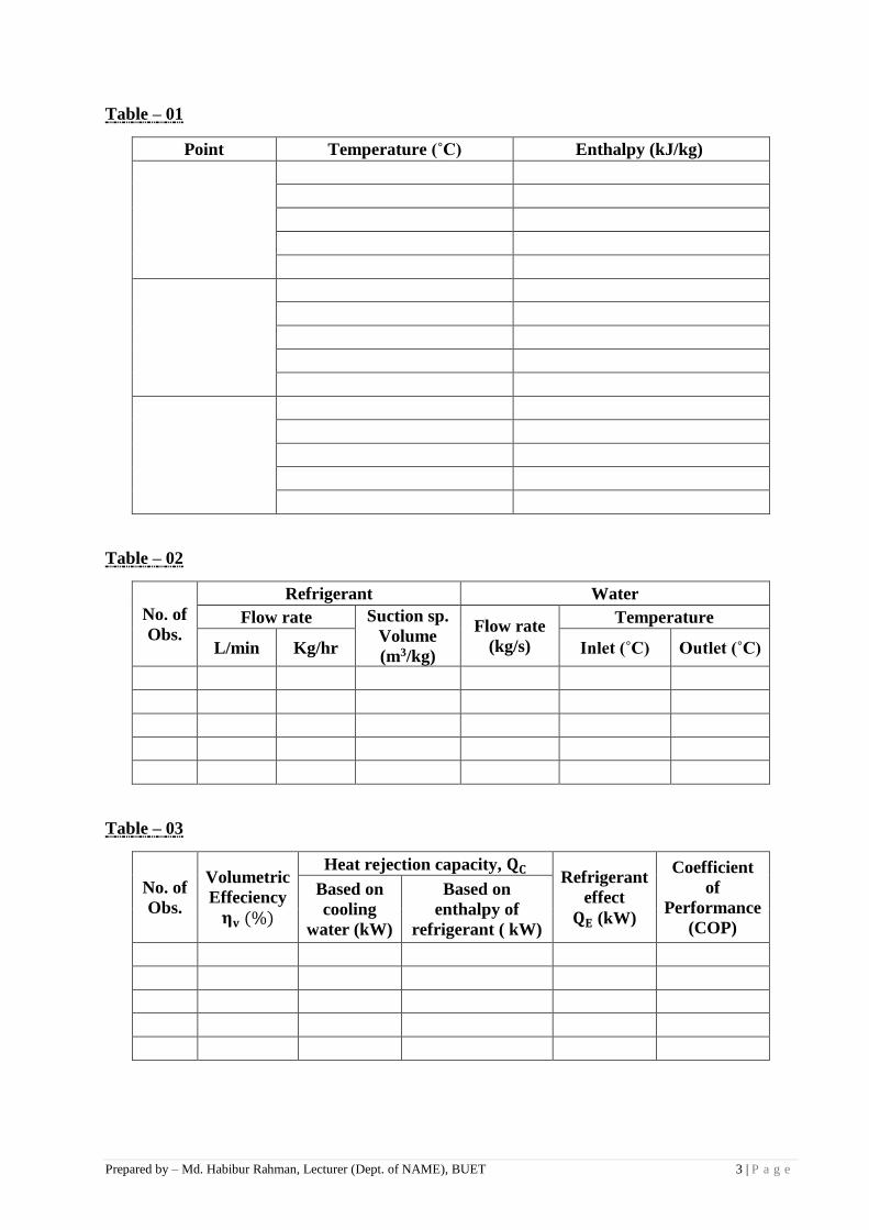
Data Sheet
A. Observation Table
Start the refrigerating unit and allow some time to bring it to steady state condition. Then
take temperature, pressure readings at different state points (as available). Measure flow
rates of refrigerant and condenser water.
Wa
tt
Met
er
Ice
Ca
n
Tem
p.
T9
(˚C
)
Bri
ne
Ev
ap
ora
tor
Tem
p. Ou
t
T6
(˚C
)
In
T5
(˚C
)
Cooli
ng
wate
r
Con
den
se
r T
emp
.
Ou
t
T8
(˚C
)
In
T7
(˚C
)
Flo
w r
ate
of
ref.
(liq
)
(L/m
in)
Evap
.
Ou
tlet
Tem
p.
(R-1
2)
T4
(˚C
)
Con
d.
Ou
tlet
Tem
p.
(R-1
2)
T3
(˚C
)
Com
p.
Sp
eed
(r.p
.m.)
Co
mp
ress
or Tem
per
atu
re
Del
iver
y
Tem
p.
T1
(˚C
)
Su
ctio
n
Tem
p.
T1
(˚C
)
Pre
ssu
re
Del
iver
y
Pre
ssu
re
P2
(kg
/cm
2)
Su
ctio
n
Pre
ssu
re
P1
(kg/c
m2)
Per
iod
Prepared by – Md. Habibur Rahman, Lecturer (Dept. of NAME), BUET 3 | P a g e
Table – 01
Point Temperature (˚C) Enthalpy (kJ/kg)
Table – 02
No. of
Obs.
Refrigerant Water
Flow rate Suction sp.
Volume
(m3/kg)
Flow rate
(kg/s)
Temperature
L/min Kg/hr Inlet (˚C) Outlet (˚C)
Table – 03
No. of
Obs.
Volumetric
Effeciency
𝛈𝐯 (%)
Heat rejection capacity, 𝐐𝐂 Refrigerant
effect
𝐐𝐄 (kW)
Coefficient
of
Performance
(COP)
Based on
cooling
water (kW)
Based on
enthalpy of
refrigerant ( kW)
Prepared by – Md. Habibur Rahman, Lecturer (Dept. of NAME), BUET 4 | P a g e
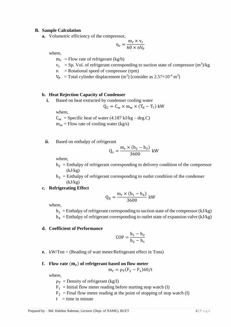
B. Sample Calculation
a. Volumetric efficiency of the compressor,
ηv =mr × vr
60 × nVP
where,
mr = Flow rate of refrigerant (kg/h)
vr = Sp. Vol. of refrigerant corresponding to suction state of compressor (m3)/kg
n = Rotational speed of compressor (rpm)
VP = Total cylinder displacement (m3) [consider as 2.57×10⁻⁴ m3]
b. Heat Rejection Capacity of Condenser
i. Based on heat extracted by condenser cooling water
QC = Cw × mw × (T8 − T7) kW
where,
Cw = Specific heat of water (4.187 kJ/kg – deg.C)
mw = Flow rate of cooling water (kg/s)
ii. Based on enthalpy of refrigerant
Qc =mr × (h2 − h3)
3600 kW
where,
h2 = Enthalpy of refrigerant corresponding to delivery condition of the compressor
(kJ/kg)
h3 = Enthalpy of refrigerant corresponding to outlet condition of the condenser
(kJ/kg)
c. Refrigerating Effect
QE =mr × (h1 − h4)
3600 kW
where,
h1 = Enthalpy of refrigerant corresponding to suction state of the compressor (kJ/kg)
h4 = Enthalpy of refrigerant corresponding to outlet state of expansion valve (kJ/kg)
d. Coefficient of Performance
COP =h1 − h2
h2 − h1
e. kW/Ton = (Reading of watt meter/Refrigerant effect in Tons)
f. Flow rate (𝐦𝐫) of refrigerant based on flow meter
mr = ρT(F2 − F1)60/t where,
ρT = Density of refrigerant (kg/I)
F1 = Initial flow meter reading before starting stop watch (I)
F2 = Final flow meter reading at the point of stopping of stop watch (I)
t = time in minute

Prepared by – Md. Habibur Rahman, Lecturer (Dept. of NAME), BUET 5 | P a g e
C. Assignments
Inspect the unit and answer the following - - -
a. What is the type of condenser?
b. What is a solenoid valve and why is it used?
c. What is the purpose of using a sight glass?
d. Why liquid to suction gas heat exchanger is used?
e. What are the functions of an expansion valve? What type of expansion valve is used
here?
f. Why brine tank is insulated?
g. Why high pressure & low pressure switches are used in refrigerating system?
h. What is the speed of the motor and what is the number of poles of the motor?
i. What are the functions of an Air Handling Unit (AHU) and a Fan Coil Unit (FCU)?
D. Discussion
Discuss the above study and express your comments regarding the experiment.