nafnoise and fast noise module - wind.nrel.gov workshop... · • users guide • some validation...
TRANSCRIPT

1Operated for the U.S. Department of Energy Office of Energy Efficiency and Renewable Energy by Midwest Research Institute • Battelle
NAFNoise and FAST Noise Module
TurbSim & Design Codes Workshop
September 25, 2008
Pat Moriarty

2
Innovation for Our Energy Future National Renewable Energy Laboratory
Outline
• Noise mechanisms• Code Descriptions• Simple Models
– 2D Data Comparison– Full Turbine Comparison
• More complex Models– 2D data Comparison
• Inputs & Outputs• Future Work

3
Innovation for Our Energy Future National Renewable Energy Laboratory
Technical report
• NREL/TP 500-34478• http://www.nrel.gov/docs/fy04o
sti/34478.pdf • Theory manual• Users guide• Some validation• See also Moriarty 2004 ASME
and Moriarty 2005 CEAS for more model detail and validation

4
Innovation for Our Energy Future National Renewable Energy Laboratory
Noise Mechanisms Two-dimensional only
Turbulent boundary layer trailing-edge Blunt trailing edge
Laminar vortex sheddingTurbulent inflow

5
Innovation for Our Energy Future National Renewable Energy Laboratory
Code Descriptions• Mostly empirical models noise models
– Brooks, Pope, & Marcolini (1989) – airfoil self noise • Based on NACA 0012 measurements• Turbulent boundary layer trailing edge, separating flow, laminar boundary layer vortex
shedding, and trailing edge bluntness vortex shedding– Amiet (1975) – turbulent inflow noise
• Flat plate formulation• Leading edge noise source
• Models with more physics– Xfoil (Drela 2001)
• Calculates boundary layer properties directly• Any airfoil shape • Tripping included
– Full or simplified Guidati turbulent inflow noise (CEAS 2005)– TNO turbulent boundary layer trailing edge (CEAS 2005)
• NAFNoise– 2D airfoil only– Standalone code
• FAST Noise module– Full turbine– No Xfoil (only in alpha version)– No Guidati turbulent inflow noise module (simplified in alpha version)– No TNO trailing Edge noise module– BPM tip noise included (1989)– No mechanical or tower wake noise or atmospheric propagation
⎟⎟⎠
⎞⎜⎜⎝
⎛∝ 2
*5log10
e
sTBL r
bMSPL δ

6
Innovation for Our Energy Future National Renewable Energy Laboratory
Full Turbine Modeling
• Rotor broken into many different segments• Airfoil noise calculated for each segment
– Relative to observer position (directivity)– Two-dimensional– Quasi-steady
• Tip Noise only 3D model• Total rotor noise is the summation of all the
segments– Time and space dependent SPL– Fully averaged spectra (OASPL)
• NOT modeled– Mechanical noise – Tower influence– Atmospheric propagation

7
Innovation for Our Energy Future National Renewable Energy Laboratory
Tip Noise
NACA 0012 Airfoil, a=10.8º, U∞
=71.3 m/sBrooks Pope, & Marcolini 1989
NACA 0012

8
Innovation for Our Energy Future National Renewable Energy Laboratory
Aeroacoustic Measurements NLR Small Aeroacoustic Wind Tunnel
• 0.38 m x 0.51 m open jet (80 m/sec)• Inflow turbulence intensity
– 1% clean: 5-9 % with grid• 48-microphone phased array 0.6 m
from model• Seven different airfoils• Re ~ 200,000 – 1 million (chord =
0.23m)• α
= 0°- 8° (corrected for jet)• Tripped airfoils – 0.25 mm zigzag tape
@ 5% l.s. & 2% u.s.

9
Innovation for Our Energy Future National Renewable Energy Laboratory
Airfoil Validation
NACA 0012
⎟⎟⎠
⎞⎜⎜⎝
⎛∝ 2
5log10e
pLBL r
bMSPL
δ
α
= 4.4°Untripped Boundary Layer

10
Innovation for Our Energy Future National Renewable Energy Laboratory
Full Turbine Comparison
• CART Turbine at NWTC– 600 kW turbine– Constant speed (41.8 rpm)
• 95 m/s tip speed (M = 0.28)• Re ~ 5 million near tip
– mod LS(1)-0417 airfoils– TE thickness ~ 1% chord
• Upwind met measurements– 2.0 diameters west-northwest– Sonic anemometer at hub height
• 3 ground-level microphones– Downwind 58 m & 99 m– Rotor plane (south) 58 m– One-minute average spectra
LS(1)-0417
NACA 0012

11
Innovation for Our Energy Future National Renewable Energy Laboratory
Full Turbine Distance
~6 dB difference in measurement and prediction

12
Innovation for Our Energy Future National Renewable Energy Laboratory
Full Turbine Mean Wind Speed
58 m downwind, δ
= 3°

13
Innovation for Our Energy Future National Renewable Energy Laboratory
Xfoil Boundary Layer Prediction
• Sound intensity proportional to boundary layer thickness (δ* or δ)
• Brooks, Pope, and Marcolini – NACA 0012 measurements– empirical formulae
• Use Xfoil (Drela, 2001) instead– Allows for any airfoil shape
• Also used for TNO TBLTE model
⎟⎟⎠
⎞⎜⎜⎝
⎛∝ 2
*5log10
e
sTBL r
bMSPL δ
⎟⎟⎠
⎞⎜⎜⎝
⎛∝ 2
5log10e
pLBL r
bMSPL
δ

14
Innovation for Our Energy Future National Renewable Energy Laboratory
Turbulent Inflow Noise Guidati Model
• Based on method of Guidati et al. (1997)
• Produces correction to flat plate estimate
• Acoustic analogy of Möhring (1979)
– Steady, inviscid, and incompressible potential base flow
– Turbulent gusts modeled by discrete sheets
– Sheets carry vorticity– Vorticity determined from von
Karman spectrum
Grosse Wellenzahl
2Δζ2/λ ≈ 1 !!
LD/λ >> 1 ok
λ
λ
dBSPLSPLSPL GuidatiAmietInflow 10++=
( ) φ022 iHeMii eBHeB U×⋅−∇=+∇ ω
( ) ( )UU ×⋅−∇=∇⋅++∇ ωBiHeMBHeB 022 2

15
Innovation for Our Energy Future National Renewable Energy Laboratory
Turbulent Inflow Noise Guidati Model
S822, α
= 0.0°, M=0.095, f = 2 kHz

16
Innovation for Our Energy Future National Renewable Energy Laboratory
Turbulent Inflow Noise Guidati Model
M = 0.095 α
= 4.4°
5 min./ freq. (1.7 GHz) = Too Computationally Expensive !!!

17
Innovation for Our Energy Future National Renewable Energy Laboratory
Turbulent Inflow Noise Simplified Model – Straight Line Approximation
SD2030
fx63
S822
SG6043
S834
SH3055
Dec
ambe
red
airf
oils
Strouhal number 2πfC/U (-)
Diff
eren
cein
soun
dpo
wer
leve
lSP
L Airf
oil-S
PLFl
atpl
ate
(dB
)
0 25 50 75 100-30
-20
-10
0
Origin at (-5, 0)Slope is only unknown!

18
Innovation for Our Energy Future National Renewable Energy Laboratory
Turbulent Inflow Noise Simplified Model
Inflow turbulence noise indicator IT
Slop
epa
ram
eter
SL
0 0.1 0.20
0.1
0.2
0.3
0.4
0.5
0 0.1 0.2 0.3
Drel,1%Drel,10%
V10 0.25 0.5 0.75 1
%,%, yrelxrel DADIT ⋅+=
%10,%1, relrel DDIT +=
2317.5123.1 ITITSL ⋅+⋅=
2 5fCSPL SLUπ⎛ ⎞Δ = − +⎜ ⎟
⎝ ⎠
Optimization
19
Innovation for Our Energy Future National Renewable Energy Laboratory
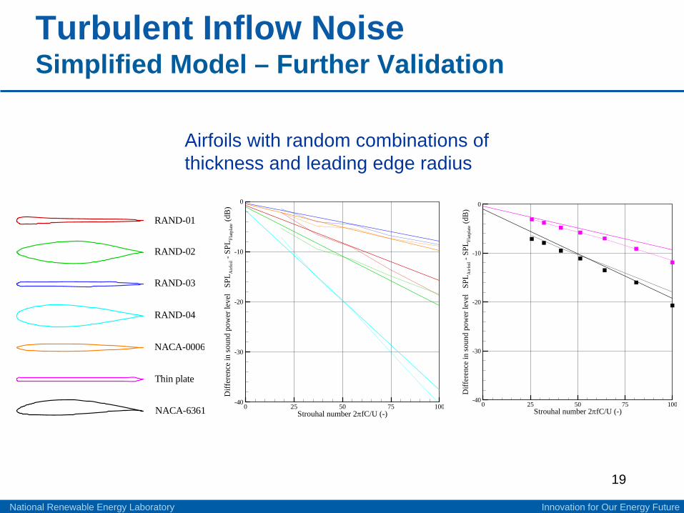
Turbulent Inflow Noise Simplified Model – Further Validation
R A N D - 0 1 R A N D - 0 2 R A N D - 0 3 R A N D - 0 4 N A C A - 0 0 0 6T h i n p l a t e N A C A - 6 3 6 1 Strouhal number 2πfC/U (-)
Diff
eren
cein
soun
dpo
wer
leve
lSP
L Airf
oil-S
PLFl
atpl
ate
(dB
)
0 25 50 75 100-40
-30
-20
-10
0
Strouhal number 2πfC/U (-)
Diff
eren
cein
soun
dpo
wer
leve
lSP
L Airf
oil-S
PLFl
atpl
ate
(dB
)
0 25 50 75 100-40
-30
-20
-10
0
Airfoils with random combinations of thickness and leading edge radius

20
Innovation for Our Energy Future National Renewable Energy Laboratory
Turbulent Boundary Layer TE Noise TNO Model
• Originally developed by R. Parchen of TNO-TPD in Netherlands
• XFOIL for B. L. parameters (Cf , δ, and Uo )
• Coles’ law of the wall & law of the wake
• Prandtl’s mixing length hypothesis
• Empirical relations for mixing length and dissipation length scales
• 4 constants tuned to NLR data
( ) ( )∫∞
=0
1110
2 ,0,4
dkkPkcR
DS ωωπ
ω
( ) ( ) ( )∫∞
−−⎟⎟⎠
⎞⎜⎜⎝
⎛∂∂
+=
02
21,13122
2
2
12222
32
1
212
0312,,4,, dxekUkk
xUuL
kkkkkP xk
cm ωφωφρω
⎟⎟⎠
⎞⎜⎜⎝
⎛⎟⎟⎠
⎞⎜⎜⎝
⎛−⎟⎟
⎠
⎞⎜⎜⎝
⎛−++⎟⎟
⎠
⎞⎜⎜⎝
⎛= Bu
uUWBxuuU
νδ
κνκ
*
*02
**
1 ln121ln1
⎟⎠⎞
⎜⎝⎛=
δκδ085.0
tanh085.0 2xlm
32
2 1
1 2 1xc
L c x e δε δ
⎛ ⎞⎛ ⎞⎜ ⎟− −⎜ ⎟⎜ ⎟⎝ ⎠⎝ ⎠
⎛ ⎞⎜ ⎟= −⎜ ⎟⎜ ⎟⎝ ⎠
2
12
xUlmt ∂∂
=ν

21
Innovation for Our Energy Future National Renewable Energy Laboratory
Turbulent Boundary Layer TE Noise TNO vs. BPM
TNORe = 1.1 · 106
NACA 0012
BPMFrequency (Hz)
Soun
dpr
essu
rele
vel(
dB)
2000 4000 6000 800050
60
70
80
1000
0°, 4.5°, 9°, 12°, 16.5°

22
Innovation for Our Energy Future National Renewable Energy Laboratory
Turbulent Boundary Layer TE Noise TNO vs. BPM
Frequency (Hz)
Soun
dpr
essu
rele
vel(
dB)
2000 4000 6000 800050
60
70
80
1000
0°, 10°, 18°
TNORe = 1.0 · 106
BPM

23
Innovation for Our Energy Future National Renewable Energy Laboratory
Inputs (NAFNoise)
• Desired noise modules to use (e.g. TBL, LBL, etc..)• Boundary layer calculation (Xfoil vs. BPM)• TBLTE Noise calculation (BPM vs. TNO)• Turbulent Noise calculation (Amiet vs. full Guidati vs. simple Guidati)• Airfoil properties
– Airfoil shape (NACA automatically calculated)– Trip locations– Airfoil thickness (simple Guidati model)– Chord, Span– Trailing edge thickness & angle
• Incoming flow– AoA, Velocity– Turbulence intensity, length scale– Speed of sound, viscosity, and density
• Observer position

24
Innovation for Our Energy Future National Renewable Energy Laboratory
Inputs (FAST Noise Module)
• Desired noise modules to use (e.g. TBL, LBL, etc..)• Desired outputs
– Which noise source to use for OASPL• Speed of sound• Tip shape parameters
– Round or square– Spanwise lift distribution slope
• Observer position• Blade trailing edge thickness & angle• Many parameters passed automatically from FAST input files

25
Innovation for Our Energy Future National Renewable Energy Laboratory
Outputs - Spectra
NAFNoise - NACA 0012
M=0.207
FAST - AOC 15/50
Time Averaged

26
Innovation for Our Energy Future National Renewable Energy Laboratory
FAST Outputs – Full Turbine
Noise Footprint Rotor Plane – Doppler Amplification
AOC 15/50Time dependent

27
Innovation for Our Energy Future National Renewable Energy Laboratory
Code Observations
• Two-dimensional airfoil– Reasonable agreement with validation data depending on physics– Using XFOIL to calculate BL thickness improves TBL noise prediction– Using XFOIL to calculate BL thickness DOES NOT improve LBL-VS noise
prediction• Measurement and calculation sensitive to transition
– TNO adequate replacement for BPM• As accurate as BPM• More physical detail than BPM• A reasonable agreement with measured data• May improve with more sophisticated boundary layer information
– Guidati model accurate for turbulent inflow noise– Simplified turbulent inflow model as accurate as full boundary element
method• Full Turbine
– Absolute levels not accurately estimated– Some trends in SPL spectra predicted by the code, but not all (e.g. pitch
effect)

28
Innovation for Our Energy Future National Renewable Energy Laboratory
Future Work
• Incorporate more physical models into 3-D wind turbine code
• Validate against more full wind turbine test data• Improve turbulence length scales used in TNO• Improve BL calculation for TNO (CFD based)• Tower influence model• Atmospheric propagation

29Operated for the U.S. Department of Energy Office of Energy Efficiency and Renewable Energy by Midwest Research Institute • Battelle
Questions?
Pat Moriarty
+1 (303) 384 – [email protected]