nadir user's guide - amazon simple storage service · symbol requiring reference to the...
TRANSCRIPT

NADIR
USER'S GUIDE
September 2009 MADE - V 3.20

GU_NADIR_V_3_20_EN 2 / 20
CONTENTS
1 SAFETY INFORMATION ............................................................................................................................. 3
1.1 SAFETY RECOMMENDATIONS : ........................................................................................................................ 3
1.2 FOLLOWING THE SAFETY RECOMMENDATIONS : .................................................................................................. 3
1.3 WARNING LABELS ......................................................................................................................................... 3
1.4 DANGEROUS ENVIRONMENTS ......................................................................................................................... 4
2 OVERVIEW ................................................................................................................................................ 5
3 NADIR COMPONENTS ............................................................................................................................... 6
4 NADIR TRANSMITTER ............................................................................................................................... 7
4.1 CONNECTION OF THE TRANSMITTER ................................................................................................................. 8
5 NADIR RECEIVER ....................................................................................................................................... 9
6 USING NADIR RECEIVER .......................................................................................................................... 10
6.1 USING THE INTERNAL TRANSDUCER ................................................................................................................ 12
6.2 USING THE EXTERNAL TRANSDUCER ............................................................................................................... 12
6.3 USING THE MADE-FLEX ROGOWSKI COIL TO IDENTIFY A PHASE ......................................................................... 13
7 NADIR OPERATION ................................................................................................................................. 14
8 TECHNICAL CHARACTERISTICS ................................................................................................................ 16
9 MAINTENANCE ....................................................................................................................................... 17
10 RECYCLING .......................................................................................................................................... 17
11 GUARANTEE ........................................................................................................................................ 18
11.1 LIMITATIONS ............................................................................................................................................. 18
11.2 CLAIMS LIMITATIONS ................................................................................................................................... 18
12 COPYRIGHT ......................................................................................................................................... 19
13 APPENDIX ........................................................................................................................................... 20
13.1 CE CONFOMITY ......................................................................................................................................... 20

GU_NADIR_V_3_20_EN 3 / 20
1 SAFETY INFORMATION
1.1 Safety recommendations : Please read this manual carefully before unpacking, configuring or using this equipment. Note all indications of danger and other warnings. The failure to observe these recommendations could result in serious injury to the operator or could damage the equipment. To ensure that the protection provided by this equipment is appropriate, do not use or install it other than in accordance with the conditions indicated in this manual. Dismantling the cases is forbidden. This operation is limited exclusively to personnel qualified by MADE.
1.2 Following the safety recommendations : DANGER : Indicates a dangerous or potentially dangerous situation which, if not avoided, could cause serious or deadly injuries. NOTE : Indicates a potentially dangerous situation which could cause superficial to moderate injuries. Remark : Information that merits mention.
1.3 Warning labels Read all labels and wordings shown on the instrument. Bodily injury or equipment damage could occur if these instructions are not respected.
Symbol requiring reference to the instruction manual for instructions concerning operation or safety recommendations
Dangerous voltage
AC current
IP standard – Protection against dust and water : TRANSMITTER
IP standard – Protection against dust and water : RECEIVER
IP 65
IP 22

GU_NADIR_V_3_20_EN 4 / 20
1.4 Dangerous environments DANGER : Even though some of the systems supplied by MADE are designed and certified for installation in dangerous environments, several MADE systems are not intended for use in such environments. It is incumbent upon those who install these systems in dangerous environments to determine the acceptability of the system for its environment. Additionally, to guarantee safety, the installation of systems in dangerous environments must be compliant to the order specification of the manufacturer. Any modification of systems or their installation is not recommended and could cause deadly injuries and/or damage to facilities.
GU_NADIR_V_3_20_EN 5 / 20
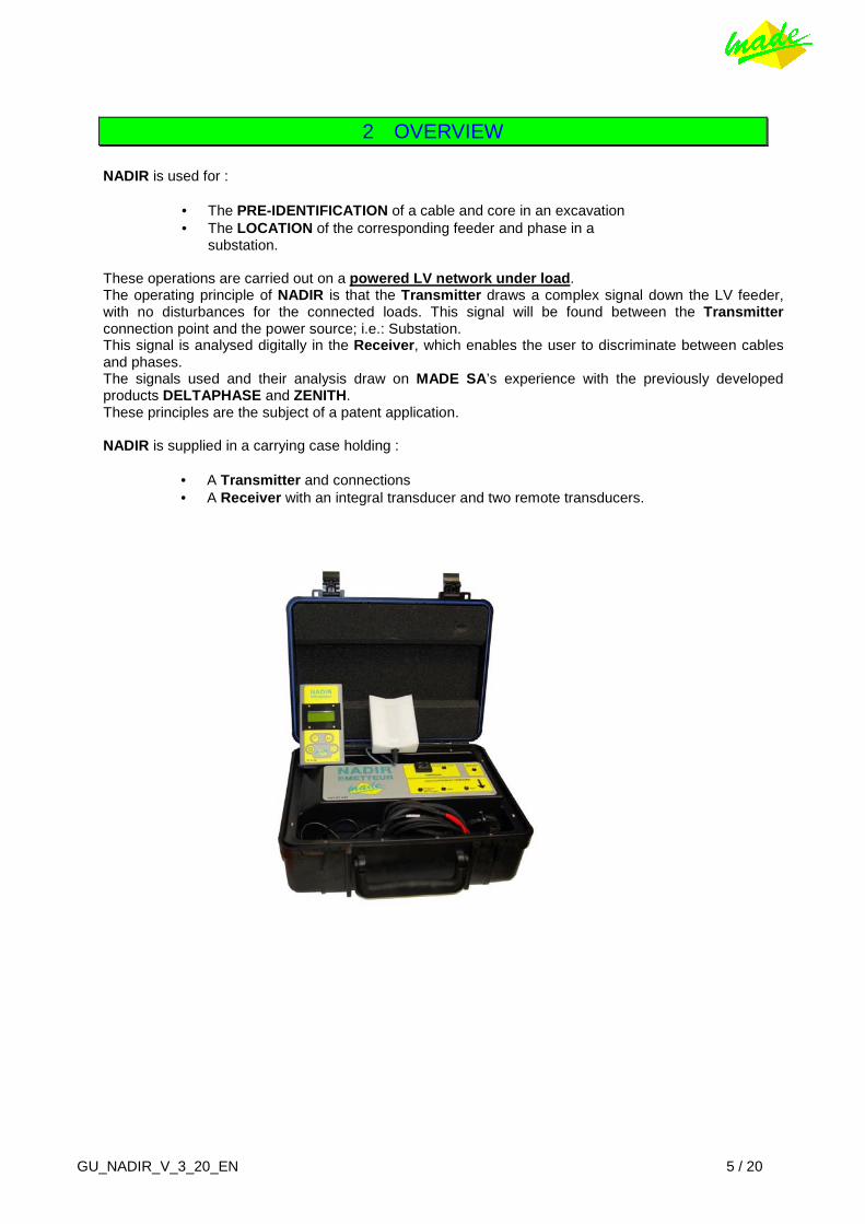
2 OVERVIEW NADIR is used for :
• The PRE-IDENTIFICATION of a cable and core in an excavation • The LOCATION of the corresponding feeder and phase in a
substation. These operations are carried out on a powered LV network under load . The operating principle of NADIR is that the Transmitter draws a complex signal down the LV feeder, with no disturbances for the connected loads. This signal will be found between the Transmitter connection point and the power source; i.e.: Substation. This signal is analysed digitally in the Receiver , which enables the user to discriminate between cables and phases. The signals used and their analysis draw on MADE SA ’s experience with the previously developed products DELTAPHASE and ZENITH. These principles are the subject of a patent application. NADIR is supplied in a carrying case holding :
• A Transmitter and connections • A Receiver with an integral transducer and two remote transducers.

GU_NADIR_V_3_20_EN 6 / 20
3 NADIR COMPONENTS TRANSMITTER :
� Integral carrying case � 1 Cable for the connection to the network
(phase-phase or phase-neutral) � 2 crocodile clips � Integral charger for the receiver � 1 mains cable (230 V ∼) for the charger � 1 link cable for charging the receiver.
RECEIVER : � Polycarbonate cased hand-held with
display screen and integral cable transducer.
� Remote transducer for cable pre-identification
� MADE-Flex (Rogowski coil) for locating the phase(s).
The charger for Receiver battery pack is integrated into the Transmitter . To charge the Receiver , connect the Transmitter to a 230 V ∼ supply, and connect the Receiver with the cable supplied. The level of charge of the Receiver is shown on the last page of the Receiver display. This reading will only be correct when the Receiver is disconnected from the charger and the charging cable.

GU_NADIR_V_3_20_EN 7 / 20
4 NADIR TRANSMITTER The Transmitter is connected, using the crocodile clips provided, either between any two phases, or between any phase and neutral on the feeder, downstream of the point of interest.
THE TRANSMITTER AUTOMATICALLY ADJUSTS TO THE VOLTAGE SUPPLIED .
� Turning ON the TRANSMITTER :
• Connect the 2 crocodile clips between PHASE and NEUTRAL or between PHASES, depending on the kind of network (The fan starts)
• Pressing the push button once, located in the "TRANSMITTING" area, starts the emission
• The yellow LED flashes showing the going-on emission • Turn down the cover, do not try to lock it • Start measuring with the RECEIVER.
A LED indicates the presence of the supply (230 V or 400 V). The Transmitter is started by switching it ON, and a flashing green LED indicates correct operation. In the presence of an internal fault, the red FAULT lamp will light. Should this occur, turn OFF, check the connections and re-start. If the fault persists, contact : NIS, A. T. M. S. or the manufacturer. The NADIR Transmitter monitors its internal voltages, the cooling fan and the overall operation. So as to improve reception, try to connect the Transmitter as close as possible downstream of the point of interest.
� Stopping the TRANSMITTER :
• Press the push button, used to turn ON the Transmitter. • The yellow LED stops flashing, the fan is still in operation • Disconnect the crocodile clips from the network, the fan stops.
BT HTA
Connection: Phase-Neutral
or Phase-Phase
N Ph Ph
HB
Transmitter
Receiver using internal sensor
Receiver using external sensor
Receiver using Rogowski coil

GU_NADIR_V_3_20_EN 8 / 20
4.1 Connection of the Transmitter
Phase-to-Phase connection in a link box
Phase-to-Neutral connection in a link box

GU_NADIR_V_3_20_EN 9 / 20
5 NADIR RECEIVER The Receiver assembly includes :
� The Hand-held with control buttons and display with an integral transducer � The Cable Pre-identification transducer � The MADE-Flex Rogowski coil transducer for Phase identification.
Battery pack : The last menu page indicates the level of charge of the integrated battery pack. This reading will only be correct when the Receiver is disconnected from the charger and the charging cable. To recharge the battery pack, connect the link cable to the charger in the NADIR Transmitter and connect this in turn to the mains (230 V∼). Receiver battery life : 5 hours in normal use. Charging time : 10 hours (when completely discharged). When the Receiver detects a charge level of 20 %, the display indicates this and turns OFF. Then, recharge the Receiver . Turn-off after 5 seconds.
Battery level
20 % Recharge !

GU_NADIR_V_3_20_EN 10 / 20
6 USING NADIR RECEIVER
� To start the Receiver : Press ON The software version number and the telephone number of MADE-SA are shown. � To use with the cable pre-identification Transducer
• Connect this Transducer • Place the Transducer on the cables, one by one to find the highest signal.
� To use with the integral Transducer
• Do not connect a Transducer to the Receiver • Place the back of the Receiver on the cable and proceed as above.
� Menu :
• Press VALID to enter the configuration page: Backlighting ON - OFF Memo Max ON - OFF
• Memo Max : display the largest signal value in the series of measurements, in addition to the latest value.
After configuration, press SCROLL .
NADIR V3.00 WWW.MADE-SA.COM Tel. : +33.494.083.198
MADE SA
CONFIGURATION ←
LIGHTING : MEMO MAX :

GU_NADIR_V_3_20_EN 11 / 20
� Menu SEARCH : for quickly locating a cable carrying the transmitter signal :
Press VALID :
• The bar graph continuously indicates the signal level measured in percent • The signal reading is updated every 2 seconds.
The measurement is instantaneous and in real time. Press VALID and SCROLL :
� Menu IDENTIFICATION : for a more precise discrimination between cables and phases :
The measurement is made with more sophisticated algorithms in order to better identify the transmitted signal, and integrated over 5 seconds. The SEARCH function enables quick location of the cable sought. The IDENTIFICATION function confirms this for cables and phases with more precision and leaves the signal level value on the screen together with the highest value in the sequence if the Memo Max function is activated.
SEARCH
Level xx %
IDENTIFICATION
Level xx %

GU_NADIR_V_3_20_EN 12 / 20
6.1 Using the internal Transducer
Correct Position Wrong Position
6.2 Using the external Transducer

GU_NADIR_V_3_20_EN 13 / 20
6.3 Using the MADE-FLEX Rogowski coil to identify a phase
Rogowski coil

GU_NADIR_V_3_20_EN 14 / 20
7 NADIR OPERATION
� " CABLE PRE-IDENTIFICATION " function :
There are two options :
• The remote Transducer is placed on the cable • Or just the Receiver , using the internal Transducer .
The measurement is carried out at the point of interest. Since the conductors are twisted in the cable, and the modulation is between one phase and neutral or between 2 phases, move the Transducer along or around the cable to seek the best signal. This operation is first done in SEARCH mode, which gives an instantaneous measurement (acquisition time ∼ 2 seconds). During the acquisition, hold the transducer still. When a significant signal is found, change to IDENTIFICATION mode, which gives a measurement integrated over 5 seconds. As an indication, drawing on our experience, the minimum values found on the correct cable are around 35 to 40 % (according to the network and it’s load). In ideal circumstances, the received level is from 70 % to 90 %. On the "wrong " cables or phases, the signal is < 10 %.
3 Cables in the trench
∼ 1 m
Measurement Measurement Measurement 1 2 3 with the NADIR Receiver
GU_NADIR_V_3_20_EN 15 / 20
� In " PHASE IDENTIFICATION " mode :
• Connect the « MADE-FLEX » (Rogowski coil) Transducer to the Receiver The Receiver differentiates automatically between Transducers. Note : Do not put this Transducer around the cable or the screen, only the Phase to be measured, or only the Neutral of the feeder, depending on the Transmitter connection. • Close the « MADE-FLEX » coil.
� The menus SEARCH or IDENTIFICATION are used as above :
As an indication, the minimum levels observed should be between 30 % and 100 % (depending on the network and loads). On the "wrong" cables, the signal is < 10 %.
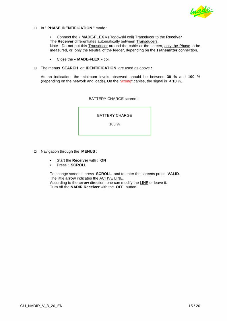
BATTERY CHARGE screen :
� Navigation through the MENUS :
• Start the Receiver with : ON • Press : SCROLL
To change screens, press SCROLL and to enter the screens press VALID . The little arrow indicates the ACTIVE LINE. According to the arrow direction, one can modify the LINE or leave it. Turn off the NADIR Receiver with the OFF button.
BATTERY CHARGE
100 %

GU_NADIR_V_3_20_EN 16 / 20
8 TECHNICAL CHARACTERISTICS
� Weight : 13 kg
• Transmitter : 12 kg • Receiver : 1 kg
� Dimensions :
• Transmitter : 549 x 371 x 229 mm • Receiver : 320 x 110 x 45 mm
� Transmitter supply :
• From a 230 V ∼ mains cable, between Phase and Neutral or between 2 Phases. • Consumption : 4 A • Fuse on the front face of the Transmitter, power : 10 AHPC • Charger : 200 mA • Crocodile clip with : 10 AHPC fuses. • Range of voltage : 185 V to 250 V or 350 V to 420 V.
� Receiver supply :
• Internal battery pack autonomy : 5 hours in normal use.
� International Standards applied :
• CEM Standards • NF EN 61 000-6-1 • NF EN 61 000-6-3 • NF EN 61 000-3-2 • NF EN 61000-3-3,
as well as the technical specifications ST BT 840 ind. C from November 2000 • NF EN 61243-3 • NF EN 60529 • NFC20-030

GU_NADIR_V_3_20_EN 17 / 20
9 MAINTENANCE Dismantling systems is forbidden. This operation is limited exclusively to personnel qualified by MADE. An annual inspection can be carried out in our premises. Never use solvent, or a solvent-based product, to clean the system and / or its accessories. For cleaning and maintenance of NADIR, it is sufficient to :
� Check that the Transducers are clean : wipe off with a dry cloth � Do not use corrosive products to clean the faces � Use only the accessories delivered with the system � In the event of a technical problem, request assistance from :
MADE-SA - Tel. :+33 494 083 198 or A. T. M. S. - Tel.: 07 717 763 510 or
Norwich Instruments Services - Tel.: 01 603 416 900 for U.K. market.
� Perform a yearly check on the operation :
Any breakdowns Calibration of Transmitter and Receiver Battery state.
10 RECYCLING
In accordance with the decree n° 2005-829 of July 2 0, 2005 relating to the waste disposal of electrical
equipment and electronic (WEEE), the user ensures and takes responsibility for the collection and the
elimination of the WEEE under the conditions of the articles 21 and 22 of this decree.

GU_NADIR_V_3_20_EN 18 / 20
11 GUARANTEE MADE guarantees this product, to the initial purchaser, against all material or functional failure during a period of one year from the date of delivery, unless otherwise indicated in the product manual. If a defect is discovered during the period of the guarantee, MADE agrees, at its choice, to either repair or replace the deficient part, excluding the expenses of handling and of initial delivery. All parts repaired or replaced under the terms of this agreement will be guaranteed only for the remainder of the period of initial guarantee of the system.
11.1 Limitations This guarantee does not cover: • Damage caused by a "cause beyond control", natural disasters, strikes, wars (declared or not), terrorism, social conflicts or any acts under governmental jurisdiction • Damage due to misuse, to carelessness, to any accident or an unsuitable application or installation • Damage caused by a repair or an attempted repair not authorized by MADE • Any product that is not used in accordance with the instructions provided by MADE • Cost of transport back to MADE • Cost of transport by express delivery of parts or products under guarantee • Cost travel for a repair on site under guarantee This guarantee constitutes the unique explicit guarantee established by MADE for its products. All implied guarantees, including, but not limited to, guarantees on the commercial value of the product and its suitability for a particular use are positively rejected. The present guarantee confers certain rights : the legislation of the country or jurisdiction can grant others. This guarantee constitutes the final declaration, complete and exclusive, of the terms of the guarantee and no body is allowed to give other guarantees or promises on MADE’s account.
11.2 Claims limitations Claims having for object repair or replacement are the only allowable claims in case of the breaking of this guarantee. The MADE Company cannot be held responsible, whether on the basis of strict responsibility or any other legal basis, of any incidental or consecutive damage resulting from a violation of the guarantee or from carelessness.

GU_NADIR_V_3_20_EN 19 / 20
12 COPYRIGHT © All reserved rights. The distribution and the copying of this document, as well as the use and the communication of its content, are forbidden without written authorization of MADE. The content of this document is destined for use only as information. It can be modified without prior notice and must not be considered as an obligation by MADE. MADE declines all responsibility for mistakes or inaccuracies that the present document may contain.
GU_NADIR_V_3_20_EN 20 / 20
13 APPENDIX
13.1 CE Confomity The Society :
declares by this document that the product described in this manual, that is :
NADIR
conforms to the following directives , including all the applicable amendments : Référence Titre 73/23/CEE 89/336/CEE
Low Voltage Directive ( LVD ) Electromagnetic Compatibility Directive ( EMC )
and that the standards and/or technical specifications listed in this manual have been applied. The designated product has been designed, manufactured and tested in the framework of a Quality Assurance System certified as conforming to the standard :
ISO 9001 : 2008 par l'Association Française pour l'Assurance Qualité - AFAQ. Certificat : QUAL / 2005 / 24473B Du : 07 / 05 / 2009
D. SPADA P.D.G.