nace rp 0178
DESCRIPTION
Recommended PracticeTRANSCRIPT

~~ ~~
NACE RPO378 95 6452983 0500933 274
NACE Standard RPO178-95 Item No. 21022
Infonnlng aie World on Corrosion Control
Standard Recommended Practice
Fabrication Details, Sutface Finish Requirements, and Proper Design Considerations for Tanks
and Vessels to Be Lined for Immersion Service This NACE International standard represents a consensus of those individual members who have reviewed this document, its scope, and provisions. Its acceptance does not in any respect preclude anyone,whether he has adopted the standard or not, from manufacturing, marketing, purchasing, or using products, processes, or procedures not in conformance with this standard. Nothing contained in this NACE International standard is to be construed as granting any right, by implication or otherwise, to manufacture, sell, or use in connection with any method, apparatus, or product covered by Letters Patent, or as indemnifying or protecting anyone against liability for infringement of Letters Patent. This standard represents minimum requirements and should in no way be interpreted as a restriction on the use of better procedures or materials. Neither is this standard intended to apply in all cases relating to the subject. Unpredictable circumstances may negate the usefulness of this standard in specific instances. NACE International assumes no responsibility for the interpretation or use of this standard by other parties and accepts responsibility for only those official NACE International interpretations issued by NACE International in accordance with its governing proce- dures and policies which preclude the issuance of interpretations by individual volunteers.
Users of this NACE International standard are responsible for reviewing appropriate health, safety, environmental, and regulatory documents and for determining their applicability in relation to this standard prior to its use. This NACE International standard may not necessarily address all potential health and safety problems or environmental hazards associated with the use of materials, equipment, andior operations detailed or referred to within this standard. Users of this NACE International standard are also responsible for establishing appropriate health, safety, and environ- mental protection practices, in consultation with appropriate regulatory authorities if necessary, to achieve compliance with any existing applicable regulatory requirements prior to the use of this
CAUTIONARY NOTICE: NACE International standards are subject to periodic review, and may be revised or withdrawn at any time without prior notice. NACE International requires that action be taken to reaffirm, revise, orwithdrawthis standard no laterthan five yearsfrom the date of initial publication. The user is cautioned to obtain the latest edition. Purchasers of NACE International standards may receive current information on all standards and other NACE Intemational publications by contacting the NACE International Membership Services Department, P.O. Box 21 8340, Houston, Texas 7721 8- 8340 (telephone +1 713492-0535).
, standard.
Reaffirmed September 1995 Reaffirmed March 1991
Revised 1989 Approved 1978
NACE International P.O. Box 218340
Houston, Texas 7721 8-8340 +I 71 W492-O535
O1 995, NACE International
COPYRIGHT NACE InternationalLicensed by Information Handling ServicesCOPYRIGHT NACE InternationalLicensed by Information Handling Services

NACE RPOLï8 95 = 61152983 0500932 LO O W
R PO1 78-95
Foreword
When specifying tanks for immersion service that are to be internally lined to control corrosion and prevent product contamination, special design, fabrication details, and surface finishing require- ments must be taken into consideration to obtain the desired performance of these linings. As the corrosiveness of the product increases, the design of thevessel becomes more critical, relative to the performance of the lining.
This standard is issued to present recommended practices for the design, fabrication, and surface finish of metal tanks and vessels that are to be lined for corrosion resistance and to prevent product contamination. The standard explains how the suggested practices govern the quality of lining applications. Appendix A depicts both good and bad design practices on tanks, while Appendix B contains a list of suggested responsibilities for the coating applicator to ensure the best protective coating available. Appendix C is avisual and written description of the degree of surface preparation of welds in tanks and vessels prior to lining.(’)
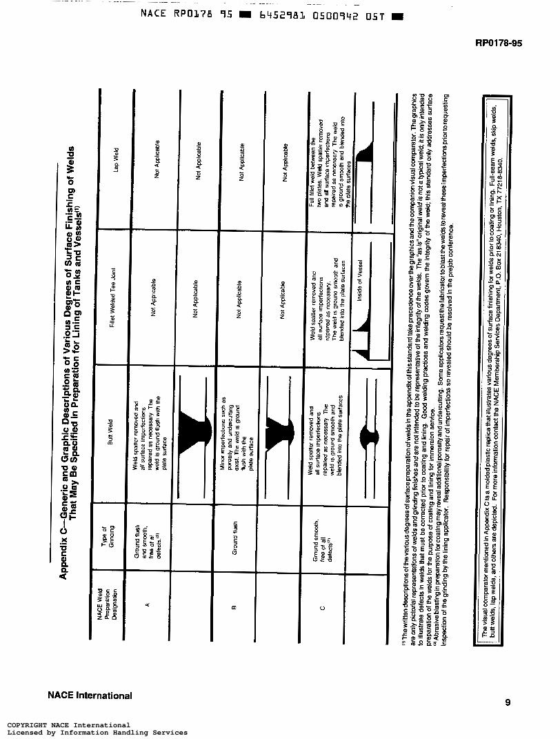
The written descriptions of the various degrees of surface preparation of welds in Appendix C of this standard take precedence overthe graphics and the companion visual comparator. The graphics are only pictorial representations of welds and grinding finishes and are not intended to be representative of the integrity of the welds. The “as is” original weld is not a typical weld; it is only intended to illustrate defects in welds that must be corrected prior to coating and lining.
Good welding practices and welding codes govern the integrity of the weld; this standard only addresses surface preparation of the welds for the purpose of coating and lining for immersion service.
This standard recommended practice was originally prepared in 1978 by NACE International Task Group T-6A-29, a component of Unit Committee T-6A on Coating and Lining Materials for Immersion Service, in collaboration with Unit Committee T-6H on Application and Use of Coatingsfor Atmospheric Service (currently titled Coating Materials for Atmospheric Service). The standard was revised in 1989 by Task Group T-6G-27, a component of Unit Committee T-6G on Surface Preparation for Protective Coatings, and was reaffirmed in 1991 and 1995. The standard is issued by NACE International under the auspices of Group Committee T-6 on Protective Coatings and Linings.
NACE International gratefully acknowledges the contributions of the following companies in the preparation of the welding samples and the fabrication of the die from which the plastic replicas have been molded:
Ausimont, Morristown, NJ Houston Lighting & Power, Houston, TX S.G. Pinney & Associates Inc., Port St. Lucie, FL The Sherwin-Williams Co., Cleveland, OH
NACE also gratefully acknowledges the assistance of KTA-Tator Inc., Pittsburgh, PA, in developing the weld pattern that was used to mold the plastic replica of weld samples.
The visual comparator mentioned in Appendix C is a molded plastic replica that illustrates various degrees of surface finishing for welds pBor to coating or lining. Full-seam welds, skip welds, but welds, lap welds, and others are depicted. For more information contact the NACE Membership SeMces Department, P.O. Box 218340. Houston, TX 77218-8340.
This standard represents a consensus of those individual members who have reviewed this document, its scope, and provisions. Its acceptance does not in any respect preclude anyone, whether he has adopted the standard or not, from manufacturing, marketing, purchasing, or using products, processes, or procedures not in conformance with this standard. Nothing contained in this NACE International standard is to be construed as granting any right, by implication or otherwise, to manufacture, sell, or use in connection with any method, apparatus, or product covered by Letters Patent, or as indemnifying or protecting anyoneagainst liabilityfor infringement of Letters Patent. This standard represents minimum requirements and should in no way be interpreted as a restriction on the use of better procedures or materials.
~~~ ~
NACE International i
COPYRIGHT NACE InternationalLicensed by Information Handling ServicesCOPYRIGHT NACE InternationalLicensed by Information Handling Services
~~~~ ~~ ~~
NACE RPO178 95 b452981 0500933 O47 = RP0178-95
NACE International Standard
Recommended Practice
Fabrication Details, Surface Finish Requirements, and Proper Design Considerations for Tanks
and Vessels to Be Lined for Immersion Service Contents
1. General .......................................................................................................................... 1 2. Design Requirements .................................................................................................... 1 3. Fabrication Requirements .............................................................................................. 2 4. Surface Finish Requirements ........................................................................................ 2 Appendix A-Fabrication Details, Surface Finish Requirements, and
Proper Design Considerations for Metal Tanks and Vessels to Be Lined for Immersion Service .......................................................................................... 3
Appendix B-Suggested Responsibilities ......................................................................... 8 Appendix C-Generic and Graphic Descriptions of Various Degrees
of Surface Finishing of Welds That May Be Specified in Preparation for Lining of Tanks and Vessels ..................................................................................... 9
NACE International
COPYRIGHT NACE InternationalLicensed by Information Handling ServicesCOPYRIGHT NACE InternationalLicensed by Information Handling Services
NACE RPOL78 95 m b45Z98L 0500934 T83 m
RPO178-95
Section 1: General
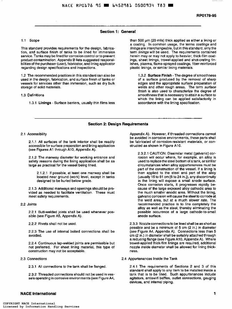
1.1 Scope
This standard provides requirements for the design, fabrica- tion, and surface finish of tanks to be lined for immersion service. Tanks may be lined for corrosion control or to prevent product contamination. Appendix B lists suggested responsi- bilities of the purchaser (user), fabricator, and lining applicator regarding design specifications and inspections.
1.2 The recommended practices in this standard can also be used in the design, fabrication, and surface finish of tanks or vessels for services other than immersion, such as dry bulk storage of solid materials.
1.3 Definitions
1.3.1 Linings - Surface barriers, usually thin films less
than 500 pm (20 mils) thick applied as either a lining or a coating. In common usage, the terms coatings and liningsare interchangeable, but in this standard, only the term linings will be used. The requirements contained herein may or may not apply to heavier, thick-film coat- ings, sheet linings, trowel-applied and shot-creting fin- ishes, plasma, flame-sprayed coatings, fiber-reinforced plastic linings, or similar lining materials.
1.3.2 Surface Finish -The degree of smoothness of a surface produced by the removal of sharp edges and the appropriate surface preparation of welds and other rough areas. The term curface finish is also used to characterize the degree of smoothness that is necessary to attain a surface to which the lining can be applied satisfactorily in accordance with the lining specification.
2.1
2.2
2.3
Section 2: Design Requirements
Access i bi I ity
2.1.1 All surfaces of the tank interior shall be readily accessible for surface preparation and lining application (see Figures A l through Alo, Appendix A).
2.1.2 The manway diameter for working entrance and safety reasons during the lining application shall be as large as practical for the vessel being lined.
2.1.2.1 If possible, at least one manway shall be located near ground (work) level, except in tanks designed to be buried below grade.
2.1.3 Additional manways and openings should be pro- vided as needed to facilitate ventilation. These must meet safety requirements.
Joints
2.2.1 Butt-welded joints shall be used whenever pos- sible (see Figure A5, Appendix A).
2.2.2 Rivets shall not be used.
2.2.3 The use of internal bolted connections shall be avoided.
2.2.4 Continuous lap-welded joints are permissible but not preferred. For sheet lining material, this type of construction may not be acceptable.
Connections 2.4
2.3.1 All connections to the tank shall be flanged.
2.3.2 Threaded connections should not be used in ves- sels operating in corrosive environments (see Figure A4,
Appendix A). However, if threaded connections cannot be avoided in corrosive environments, these parts shall be fabricated of corrosion-resistant materials, or con- structed as shown in Figure A l O.
2.3.2.1 CAUTION: Dissimilar metal (galvanic) cor- rosion will occur where, for example, an alloy is used to replace the steel bottom of a tank, or similar circumstances when alloy appurtenances must be part of the construction of the vessel. If a lining is then applied to the steel and part of the alloy (usually 15 to 61 cm [6 to 24 in.]), any discontinuity in the lining will expose a small anode surface. Once corrosion starts, it progresses rapidly be- cause of the large exposed alloy cathodic area to the much smaller anodic area. Without the lining, galvanic corrosion will cause the steel to corrode at the weld area, but at a much slower rate. The recommended practice is to line completely the alloy as well as the steel, thereby eliminating the possible occurence of a large cathode-to-small anode surface.
2.3.3 Nozzle connections to be lined shall be as short as possible and be a minimum of 5 cm (2 in.) in diameter (see Figure A4, Appendix A). Connections less than 5 cm (2 in.) in diameter shall be suitably attached through a reducing flange (see Figure Alo, Appendix A). Where trowel-applied thick-film linings are required, additional nozzle inside diameter shall be allowed for lining thick- ness.
Appurtenances Inside the Tank
2.4.1 The requirements of Sections 2 and 3 of this standard shall apply to any item to be installed inside a tank that is to be lined. Such appurtenances include agitators, antiswirl baffles, outlet connections, gauging devices, and internal piping.
NACE International 1
COPYRIGHT NACE InternationalLicensed by Information Handling ServicesCOPYRIGHT NACE InternationalLicensed by Information Handling Services

NACE RPO178 95 6952981 0500935 î 1 T m
RPO178-95
2.4.2 If appurtenances inside the tank, including nuts and bolts, cannot be lined, they shall be made of corro- sion-resistant materials. (CAUTION: See Paragraph 2.3.2.1 .)
2.4.3 If bolted connections are necessary and cannot be made of corrosion-resistant materials, the mating sur- faces shall be lined before assembly. Gaskets shall be used on mating surfaces and the sealing surfaces of nuts and bolts to protect the lining.
2.4.4 Dissimilar metals shall be electrically isolated from the steel tank surface wherever possible. Where dissimi- lar metals are used, selection shall be such that the galvanic effect is minimized. Other corrosion mitigation methods may be required (see Figure A8, Appendix A).
2.4.5 Heating elements shall be attached with a mini- mum clearance of 15 cm (6 in.) from the tank surface.
2.5 Structural Reinforcement Members
2.5.1 Structural support members should be installed on the exterior of the tank. However, if such members are installed internally, they shall be fabricated of simple shapes such as smooth round bars or pipe for ease of applying the lining material.
2.5.2 The use of internal flanged connections, stiffening rings, reinforcement pads, angles, channels, I-beams, and other complex shapes should be avoided. If they must be installed internally, these members shall be fully welded and welds and sharp edges ground and given a radius of at least 3 rnm (118 in.); 6 mm (1/4 in.) radius is preferred (see Figures A l and A6, Appendix A).
Section 3: Fabrication Requirements
3.1 All requirements given in Section 2 on Design Require- ments shall apply to all fabrication procedures.
3.2 All welding shall be continuous, Intermittent or spot weld- ing shall not be allowed.
3.3 Fillets and corners must be accessible for grinding.
3.4 Field tanks fabricated for use with high-heat-cured linings (e.g., unmodified phenol formaldehyde thermosetting coat- ings) should have bottoms suitably insulated and installed on properly drained foundations to facilitate proper cure of the lining on the floor of the tank. Because the sand-filled earthen foundation, concrete pad, or other similar foundation is a poor insulator, some means must be considered prior to the appii- cation of the lining either to override the heat sink or to distribute the heat uniformly. This can be accomplished in several ways:
(a) with the use of properly sized heaters;
(b) by placing the tank on a concrete pad topped with a 1 O-cm (4-in.) layer of vermiculite concrete;
(c) by insulating with a high-cornpressive-strength struc- tural grade insulation between the tank bottom and foundation;
(d) by installing an internal temporary false bottom ap- proximately 1.5 m (5 ft) above the floor of the tank prior to the final high-temperature bake; or
(e) by other suitable means that will practically and effectively ensure a properly cured lining on the tank floor.
Section 4: Surface Finish Requirements
4.1 Sharp edges and fillets shall be ground to asmooth radius of at least 3 mm (1/8 in.): 6 mm (1/4 in.) is preferred.
4.2 Tank surfaces to be lined shall contain no wax or grease pencil marks, gouges, handling marks, deep scratches, metal stamp marks, slivered steel, or other surface flaws. Flaws shall be repaired by solvent cleaning, welding, or grinding, as appropriate.
4.3 All rough welds shall be ground to remove sharp edges, undercuts, pinholes, and other such irregularities (see Figure A2, Appendix A). Chipping can be used to remove sharp edges if followed by grinding. See Appendix C for written and graphic descriptions of five degrees of surface finishing of welds that may be specified preparatory to the lining of tanks and vessels.
4.3.1 The amount of grinding performed shall be judi- cious; grinding shall be performed only to the extent necessary to prepare the weld surface and surrounding metal surfaces in accordance with the specification.
2
Overgrinding, which would result in decreasing the wall thickness or the integrity of the weld beyond the limita- tions imposed by good welding practices, applicable welding codes, or pressure vessel ratings, shall be avoided.
4.4 Automatic machine welds may be acceptable as dictated by the specifications for film continuity.
4.5 All weld spatter must be removed. Chipping may be used if followed by grinding or the use of an abrasive disc.
4.6 The use of an antispatter coating applied adjacent to the weld area prior to welding is suggested. The use of silicone, oil, or any other antispatter materials that would not be readily removed by abrasive blasting shall be avoided.
4.7 When checking weld continuity, the fabricatorshall avoid the use of oils or other foreign materials which would leave a contaminating residue not easily removed by abrasive blasting.
NACE International
COPYRIGHT NACE InternationalLicensed by Information Handling ServicesCOPYRIGHT NACE InternationalLicensed by Information Handling Services

~~~ ~~~~ ~~
NACE RPOL78 95 6452983 0500936 856
RPO178-95
Appendix A-Fabrication Details, Surface Finish Requirements, and Proper Design Considerations for Metal Tanks and Vessels to Be Lined for Immersion
Vessel
oreferred: 0.3-cm WE-in.1 iadiuc minimum)
DO DON'T
Figure A l
Skip Weld
2 Channels Back-to-Back
DON'T
All construction involving pockets or crevices that will not drain or that cannot be properly abrasive blasted and lined shall be avoided.
Inside of Vessel Grind Srnooth Inside of Pinhole
DO DONT
Figure A2 All joints shall be continuous fuli-penetration welds. in tanks that require a 100% holiday-free lining, all welds must be smooth with no porosity, holes, high spots, lumps, or pockets. Grinding is required to eliminate porosity, sharp edges, and high spots. The use of weld metal to fill in undercuts or pits is required for severe service conditions and/or high-bake linings. Compatible caulking materials may be used for filling in mild service such as dry bulk storage.
NACE International 3
COPYRIGHT NACE InternationalLicensed by Information Handling ServicesCOPYRIGHT NACE InternationalLicensed by Information Handling Services

RPO178-95
Inside oí
Do DON'T
Figure A3 All weid spatter shall be removed.
Weld I I c I 4
I li1 I \
SlipOn Overall Length t ' Flange Shall be as Short as
Weld
\ RoundCorners - I
DO Corners
DON'T
Pad Type Threads
Round These Corners
DO
'Inside of Vessel
Sharp Corner \
I DON'T
Figure A4 The outlets shall be flanged or pad type rather than threaded. Within pressure limitations, siip-on flanges are preferred because the inside surface of the attaching weid is readily available for radiusing and grinding. if operating pressure dictates the use of weid neck flanges, the inside surface of the attaching weid is in the throat of the nozzle, making repair of surface irregularities by grinding rather difficult.
4 NACE International
COPYRIGHT NACE InternationalLicensed by Information Handling ServicesCOPYRIGHT NACE InternationalLicensed by Information Handling Services
RPO178-95
Inside of 1 Grind Smooth Vessel J
f 9
DO
Inside of Vessel Continuous Fillet
f
DO
Inside of Vessel
5F$ji DON’T
Inside of Vessel
f 5 Ga \
T DON,T Inside oí Vessel
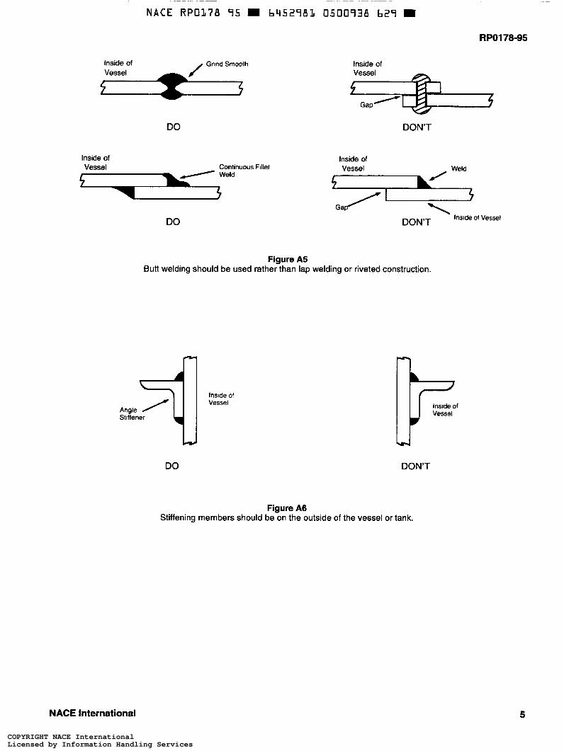
Figure A5 Butt welding should be used rather than lap welding or riveted construction.
Stiííener Angle
Inside o1 Vessel
DO
Figure A6
Inside of Vessel
æ-l
DON’T
Stiffening members should beÖn the outside of the vessel or tank.
NACE International 5
COPYRIGHT NACE InternationalLicensed by Information Handling ServicesCOPYRIGHT NACE InternationalLicensed by Information Handling Services
RPOl78-95
, A- Weld Inside-Eliminate Crevice
o Vessel ' I Insideof
- Shell
Inside of Vessel
/-
DO DONT
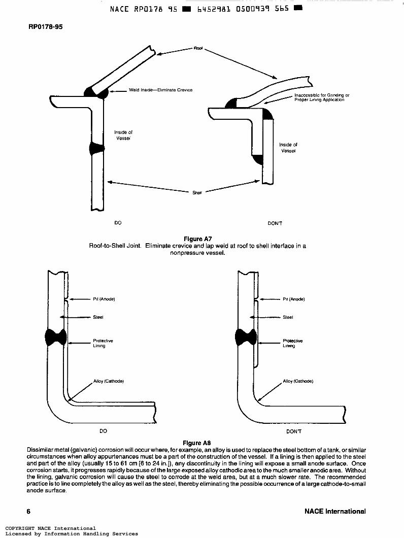
Figure A7
nonpressure vessel. Roof-to-Shell Joint. Eliminate crevice and lap weld at roof to shell interface in a
- Pit(Anode)
- Steel
I Protective Lining
Alloy (Cathode)
/
DO
f - Pit(Anode)
4 Steel
Protective Lining
#
DON7
Figure A8 Dissimilar metal (galvanic) corrosion will occur where, for example, an alloy is used to replace the steel bottom of a tank, or similar circumstances when alloy appurtenances must be a part of the construction of the vessel. If a lining is then applied to the steel and part of the alloy (usually 15 to 61 cm [6 to 24 in.]), any discontinuity in the lining will expose a small anode surface. Once corrosion starts, it progresses rapidly because of the large exposed alloy cathodic area to the much smaller anodic area. Without the lining, galvanic corrosion will cause the steel to corrode at the weld area, but at a much slower rate. The recommended practice is to line completelythe alloy as well as the steel, thereby eliminating the possible occurrence of a large cathode-to-small anode surface.
6 NACE International
COPYRIGHT NACE InternationalLicensed by Information Handling ServicesCOPYRIGHT NACE InternationalLicensed by Information Handling Services

NACE RPO178 95 6452981 0500940 287
R PO1 78-95
Screwed nipple for use during fabrication and heat curing of thermosetting linings
The plug should be left out for venting and the hole plugged with grease to prevent atmospheric corrosion of the threads
*- Installation of curved (preferred) or flat plate, fully seal-welded and ground, io eliminate inaccessible area for DroDer I I / /
I Y / surface preparation and lining in multi- compariment tanks constructed with dished heads between compartments
w Figure A9
A technique (detail of fabrication) to allow for good continuity of lining application for inaccessible areas such as in multicompartment tanks.
Slip-on flange
2.5 cm (1 in.) lhread nipple
If an alloy flange is required. the designer should consider the use of insulating sleeves and washers as a protection against galvanic corrosion
it - inside - Overalt Length Shall be as Shon as Possible
Line Completely io Boll Circle \ Y lnsi4e of Vessel
Gnnd and radius
Figure A l O Minimum 5-cm (2-in.) diameter nozzle required for most thin-film linings. Thicker-film linings may require a larger-diameter nozzle. This diagram also illustrates suggested construction where a threaded connection is required in a tank that requires a holiday-free lining.
NACE International 7
COPYRIGHT NACE InternationalLicensed by Information Handling ServicesCOPYRIGHT NACE InternationalLicensed by Information Handling Services

RPO178-95
Appendix B-Suggested Responsibilities
This section recommends responsibilities that should be as- signed to the purchaser, designer, fabricator, lining applicator, and inspector in order to obtain a properly designed and fabricated tank for interior lining.
B I .I Joint Responsibilities
B I . I .1 The purchaser, designer,fabricator, inspector(s), and applicator should review and agree to the require- ments involved before contractual agreements are made.
B I .I .2 The purchaser, in agreement with the fabricator and lining applicator, should assign responsibility for inspection of fabrication, surface finish, and lining appli- cation, and such responsibility should be defined in all contracts.
B I .2 Responsibilities of the Purchaser (Owner or User)
B1.2.1 The purchasershould be responsibleforspecify- ing and/or approving the detail requirements for design, fabrication, and surface finish to all parties concerned.
B I .2.1 .I The detailed requirements should be fully described in writing and include drawings of the tank to be fabricated and lined and service require- ments.
B1.2.1.2 The purchaser should advise the designer, fabricator, lining applicator, and all inspectors of the detailed requirements, including time schedules, inspection, and acceptable requirements, in writ- ing.
B1.3 Responsibilities of the Designer
B I .3.1 The designer should be responsible for including the requiredfabrication and surface details on all sketches and drawings related to the tank.
BI .4 Responsibilities of the Fabricator
81.4.1 The fabricator should be responsible for adher- ing to the fabrication and surface finish details shown on the working drawings and described in the tank specifi- cations.
B I .4.2 Responsibilityfor additional welding, grinding, or surface finishing that may be revealed by the surface preparation for lining, plus any subsequent reblasting, should be defined in the lining contract.
BI .4.3 The fabricator, when checking the quality of the weld, should use only those marking materials that can be readily and thoroughly removed by the fabricator after completion of the inspection procedure.
B I .5 Responsibilities of the Lining Applicator
B I .5.1 Responsibilityfor additional welding, grinding, or surface finishing that may be revealed by the surface preparation for lining, plus any subsequent reblasting, should be defined in the lining contract.
B I .6 Responsibilities of the Inspector(s)
B I .6.1 A qualified inspector should be responsible for the verification of fulfillment of design, fabrication, and su rface fin ish requirements.
8 NACE International
COPYRIGHT NACE InternationalLicensed by Information Handling ServicesCOPYRIGHT NACE InternationalLicensed by Information Handling Services
RPO178-95
m
NACE International 9
COPYRIGHT NACE InternationalLicensed by Information Handling ServicesCOPYRIGHT NACE InternationalLicensed by Information Handling Services

RPOl78-95
O
J
u w
r n
10 NACE International
COPYRIGHT NACE InternationalLicensed by Information Handling ServicesCOPYRIGHT NACE InternationalLicensed by Information Handling Services