naca tn 144 notes on the design of ailerons
TRANSCRIPT
7/27/2019 NACA TN 144 Notes on the Design of Ailerons
http://slidepdf.com/reader/full/naca-tn-144-notes-on-the-design-of-ailerons 1/14
yL?zzL’.&-dNATIONAL
.
ADVISORY CCMMIT’IEEFOR
.
No. 144
NOTES ON TKE DESIGN OF AILERONS.
By ‘W.S. 13iehljBureau of Aeronautics, U.S.N.
r
“L
b
June, 1923.
7/27/2019 NACA TN 144 Notes on the Design of Ailerons
http://slidepdf.com/reader/full/naca-tn-144-notes-on-the-design-of-ailerons 2/14
NATIONAL ADVISOR”fCOMMITTEE FOR AERONAUTICS.
TZCENICAL NOTE NO. 144.
.—— .
NOTES 01~T-HEDESIGN OF AILE20KS.*
Ey W. S. Diehl.
Recent data have shown that certain farms or types of ailer-
ons i-nextensive use, are.in reality quite inefficient and cr.-
tirely unsuited for the high speeds now realized. The same data ...
also show forms B arid
factory in every way.
C on Figure 3 to tieefficient aridsatis- .-
The most importaat of the characteristics required of ailer-
ons are:
1. Effectiveness under all conditions of flight;
2. Small moments about the hinge;
3. High efficiency (small yawing moment opposing turn);
4. Simplicity in construction.
The following notes have been compiled from various sources
in order to supply data and instructions for obtaining satisfactory
results based on the requirements just enumerated.
Chord, oz Depth.
Tests conducted at the National Physical Laboratory (British
A.C.A..R & M 550 and 615) show that the maximum rolling moment ob-
tained is practically independent of the aileron chord d, pro-
vided tha’t d is not less than about 15% of the wing chord c.
* Originally prepared as Technical Note #240, Bureau of AeroButic~Naw Department.
s.—
7/27/2019 NACA TN 144 Notes on the Design of Ailerons
http://slidepdf.com/reader/full/naca-tn-144-notes-on-the-design-of-ailerons 3/14
.
-2-
However, the greater the valtieof d/c, the greater the moments ~
. about the hinge, the greater the yawing moments (opposing turn),
and the less the rolling moments per lxpitaileron area. In gener-
al, the best results are obtained when d/c is between .20 and .30.
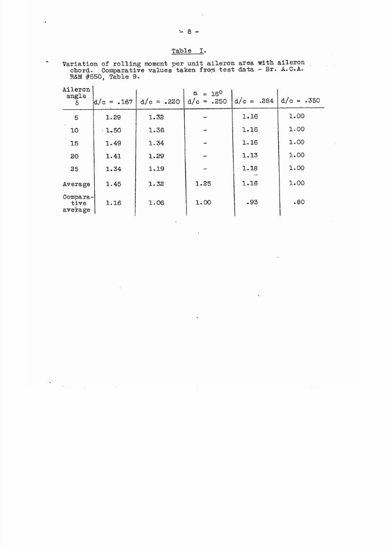
Table I contains comparative figures, taken from test data,
showing the variation of rolling moment per unit aileron area with —
the ratio d/c. In this table the rolling moment for d/c = .25
taken as unity. The average values when plotted (Fig. 1), lie
on the straight line (1) which has the equation
q~ = 1.50 - 2.00 (d/c) . . . . . . . . . . (1) ‘
where q~ is the ratio of the rolling moment per unit area, at
any given aileron setting, for an aileron whose chord is d/c, to
that for sn aileron whose chord is 25$ c (i.e. d/c = ,25).
This equation is used later to determine the variation of aileron ._..
area with plan form, retaining constant effectiveness=
EBQ”
Table 11 contains comparative
.-,.-
rolling moments per Unit aileron
azea for ailerons of various spans, as obtained in the N@L tests,
It is quite interesting to compare this experimental data With the
values predicted from the assumption that the wing area foiward of
the aileron is affected uniformly over the entire length of the
aileron. That is, the rolling moment due to an aileron will be
proportional to the product of the wing area which it affects by
the moment of this area about the center of gravity. Table III
7/27/2019 NACA TN 144 Notes on the Design of Ailerons
http://slidepdf.com/reader/full/naca-tn-144-notes-on-the-design-of-ailerons 4/14
’36
ct>ntaiasthe relative mOments per unit aileron area for ailerons
* of varying length, calculated on this assumption. The calculated —
values check the experimental values very closely as may be ~een
from Fig. 1, where the line (2) represents the calculated valueg
and the points marked with circles, the experimental
line (2) is defined by the equation
n= = (1.20 - 0,6 (L/b) )
where L/b is the ratio of aileron span
relative rolling moment per unit aileron
L/b = 1/3 as unity. This equation will
. . . . . *
values. The
. . . . .(2)
to wing span and Oa the
area referred to
be used “~ter to deter-.
mine the variation of aileroi~area witi~plan form, retaining con-
stant effectiveness=
The ratio of rolling moment to hinge moment, usually called
aileron efficiency, is found to be a maximum when L/b = 2/3.
For the best average results L/b should be greater than 0.35 .
and less than 0.70. Very long ailerons
bind at the hinges.
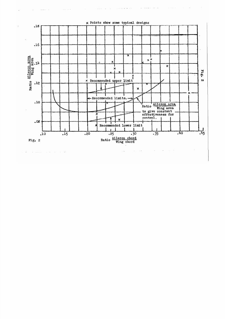
Area.—-
are liable to deflect and
For the average airplane the aileron area is about 11% of the
wing area. This would correspond to an aileron with d/c = 1/3
and L/b = 1/3.
These proportions were once in extensive use, although the
present tendency is towards narrower ailerons. Assuming that the
proportions given are satisfactory, the proportions of a series
7/27/2019 NACA TN 144 Notes on the Design of Ailerons
http://slidepdf.com/reader/full/naca-tn-144-notes-on-the-design-of-ailerons 5/14
-4-
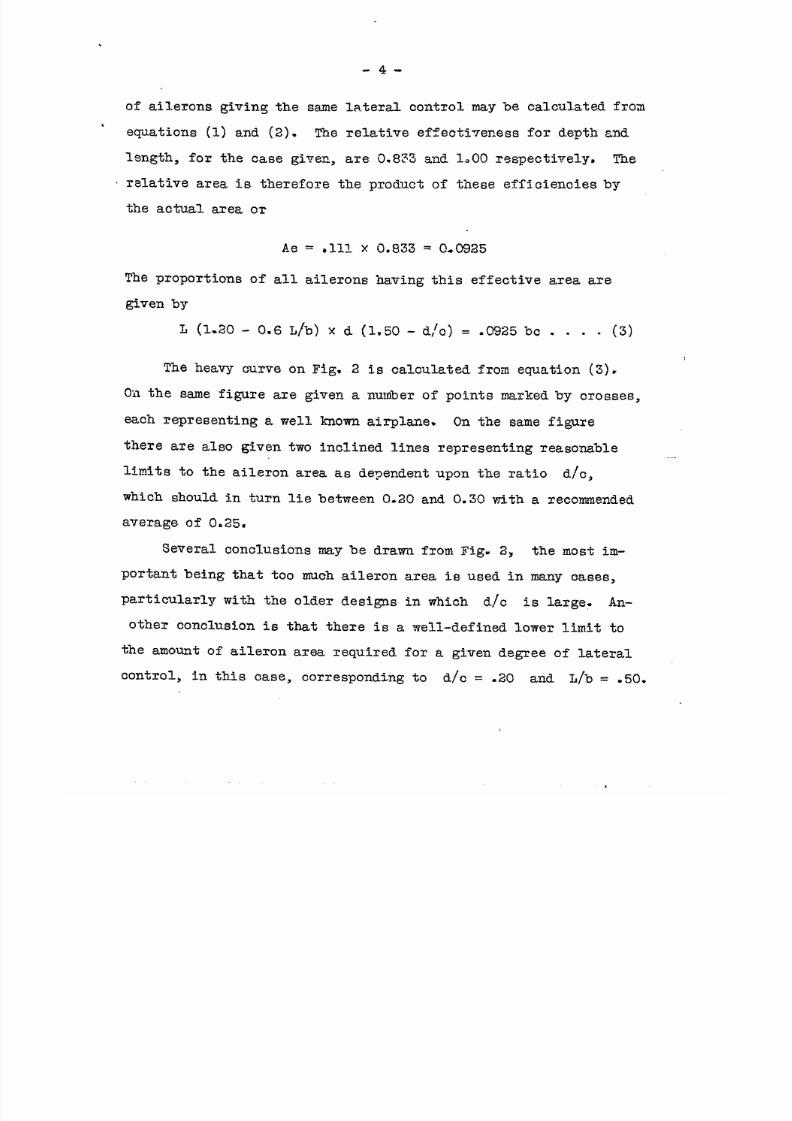
of ailerons giving the same lateral control may be calculated from
.e~iations (1) and (2). The relative effecti~eness for depth and
length, for the case given, are 0.833 and 1.00 respectively. The
“relative area is therefore the product of tineseefficienciesby
the actual axea or
Ae = ,111 X 0.833 = C!-0925
The proportions of all ailerons having this effective area are
given by
L (1.20 - 0.6 L/b) X d (1.50 - d/C) =
The heavy curve on Fig. 2 is calculated
.0925bc . . . . (3)
froa equation (3).
Oilthe same figure are given a number of points marked by crosses,
each representing a well known airplane. On the same figure
there are also given two inclined lines representing reasonable
limits to the aileron area as dependent upon the ratio d/c,
which should in turn lie between 0.20 and 0.30 with
average of 0,25.
Several conclusions may be drawn from Fig. 2Y
portant being that too much aileron area is used in
a recommended
the most im-
many cases,
particularly with the older designs in which d/c is large- An-
other conclusion is that there is a well-defined lower limit to
the amount of aileron area required for a given degree of lateral
COIltrOl, in this case, corresponding to d/c = .20 and L/b = .50.
7/27/2019 NACA TN 144 Notes on the Design of Ailerons
http://slidepdf.com/reader/full/naca-tn-144-notes-on-the-design-of-ailerons 6/14
-5-
foml
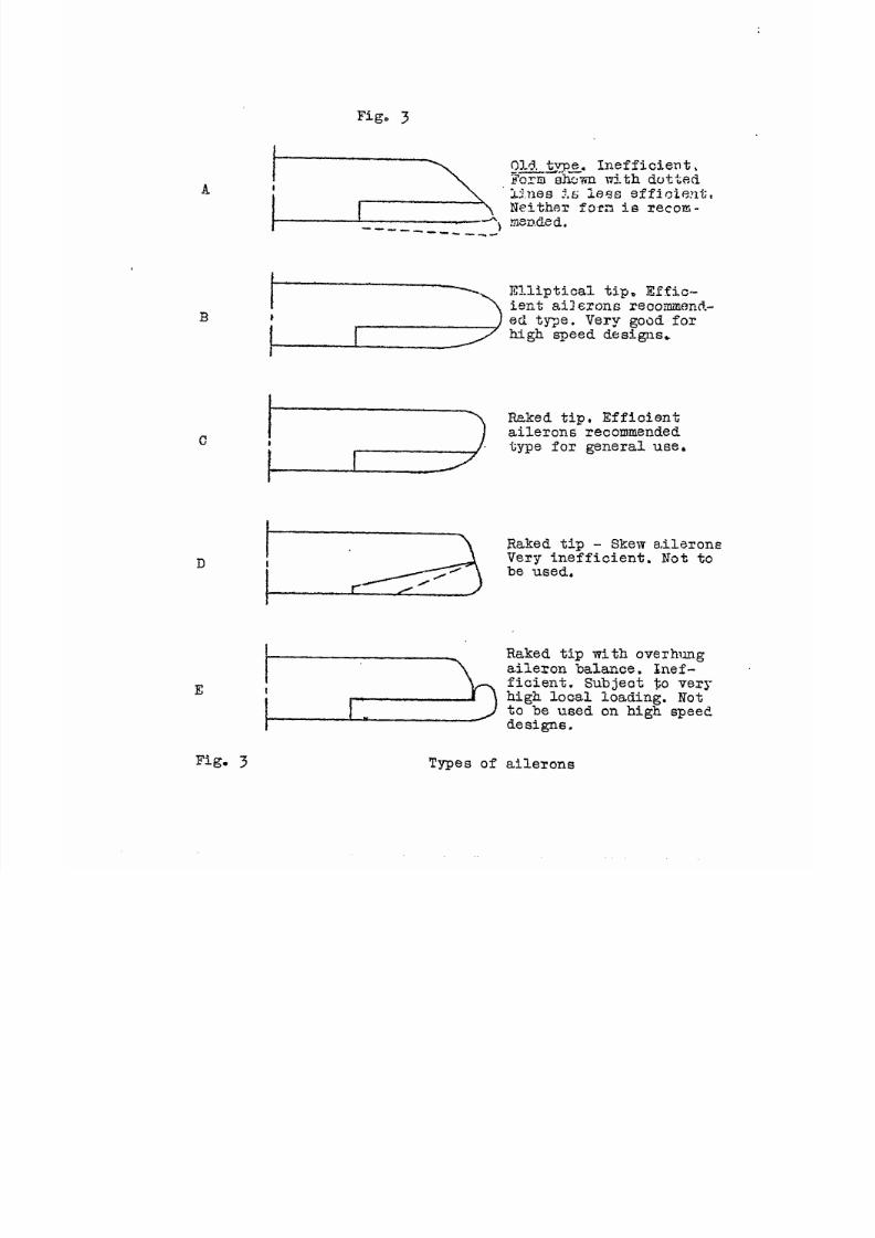
The plan form
of the wings.
tained from a wing
p~a~ fo~m.
of the ailerons is partially fixed by the plan
Tests have shown that the best results a~e ob-
tip rounded elliptically or raked with the lead-
ing edge longer than the trailing edge. The wing tips should never ._
be raked with the leading edge shorter than the trailing edge for ._
several reasons, the most important
loading which occurs on the extreme
With the ordinary construction this
of which is the extremely high
tip of this type of wing.
peak in loading comes on the
aileron and increases the hinge moments while decreasing the ail-
eron efficiency. Another reason for avoiding the wing tip raked ._
SO that the leading edge is shorter than the trailing edge, maY be
found in the behavior of the general pressure distribution on the
wing tip. It is well known that a slight washout in angle of at- —
tack towards the tip improves the performance of the mingby pre-
venting the early breakdown in lift which first takes place on the
tip, and thus equalizing the loading over the wing. It may easily
be seen that the old type of aileron shown as A in Fig. 3, give-s —-
an increase in angle towards the tip and that the flow must be
seriously disturbed..
The best plan form for an aileron is not as yet definitely -
determined, although it is knowm that certain forms such as B
and C orIFig. 3, give very good results. These forms are recom-
mended for general use..
The ‘lskew~letting is objectionable when of the form shown in
7/27/2019 NACA TN 144 Notes on the Design of Ailerons
http://slidepdf.com/reader/full/naca-tn-144-notes-on-the-design-of-ailerons 7/14
-6-
D in Fig. 3.The full effect of the angular movement is lost and4
the loading is objectionable. Difficulty is liable to be met with
this form of aileron binding when the wing deflects. The hinges -J
of all ailerons should be so arranged as to minimize the effect of
any warp or Ms% in the wing.
Qeneral Conclusions.
The following conclusions may be drawn from a study of the
references listed elsewhere in this note:
(1)
(2)
(3)
(4)
(5)
(6)
(7)
(8)
The aileron chord should be about 25% of the wing
chord - never more than 33% and never less than 20$.It is recommended that 3@ be used as the upper limit.
The aileron span should be greater than 35* of thesemi-wing span. With an aileron having tjc = .25,the span should be between 40% and 5@@ of the semi-wing span for normal control when the wing has anaspect ratio of 6.
—
In the general case the aileron area should vary from9$ to 12$ of the wing area as the aileron chordvaries from 20~ to 35% of the wing chord.
The plan form of the aileron should be such that thereis in effect a washout of angle of attack towardsthe tip - such as that given on a normal aileron onan elliptically rounded wing tip
The aileron should never extend beyond the mean tip ofthe wing.
All types of skew settings are to be discouraged.
The aileron hinges should be desi~ed to prevent binding ,if the wing deflects or twists.
Ailerons on high speed airplanes should always be of theforms B or C, or some modification of these forms,
and should be made very rigid to prevent vibration.

7/27/2019 NACA TN 144 Notes on the Design of Ailerons
http://slidepdf.com/reader/full/naca-tn-144-notes-on-the-design-of-ailerons 8/14
Refezences~..
‘*Teston RAF-6 Aerofoil with.Hinged Rear Margin*f-Washington Navy Yard, W.T.R. #34.
~fAirForces and Moments for Loening 1.1-80irplane[l- “Washington Navy Yard, W.T.R. #211.
l’AnInvestigation of the Aerodynamic Properties of
Wing Ailerons, Part Z - Effect of Variation ,ofPlan Form of Wing Tip and Span of Aileron(r-Br- A.C.A. R&M #550.
llAnInvestigation of the Aerodynamic Properties ofWing Ailerons, Part 11 - The Effect of’ Vaziationof Chord of Aileron, etc.fi- Br. AtC.A. R&M #550.
‘lPressureDistribution over Thick Aerofoilsm -
N.A .C.A. Report #150.
lfPressureDistribution over”Thick Wings ~ncludingAilerons!I– N.A.C.A. Report #161.
‘~Na.valrchitecture in Aeronauticslf(Hunsaker), 1920,July, Aeronautical Journal.
7/27/2019 NACA TN 144 Notes on the Design of Ailerons
http://slidepdf.com/reader/full/naca-tn-144-notes-on-the-design-of-ailerons 9/14
“-8-
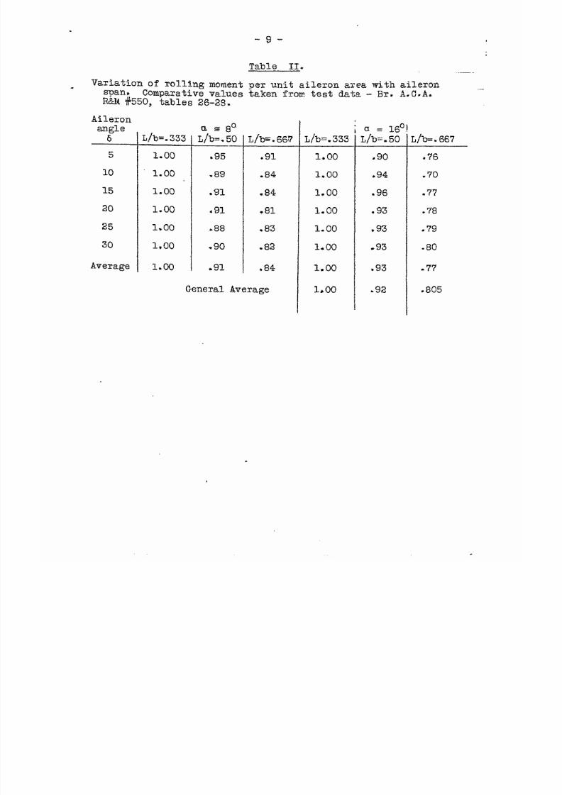
Table 1.
-.Variation of rolling moment per unit aileron area with aileron
chord. Comparative values taken fray test data - Br. A.C.A.R&M #550, Table 9-
Aileronangle
6 Id/C = .167
5
10
15
20
25
Avem ge
Corupara-tive
ave?age
1.29
1.50
1-4-9
1.41
1.34
1.45
1.16
dlc = S220
1.32
1.36
1.34
1.29
1.19
1.32
1.06
1.25
1.00
L/C = .284
1,16
1.16
1.16
1.13
1.18
.-1.16
.93
I/c = .350
1.00
1.00
1.00
1,00
1.00
1.00
.80
7/27/2019 NACA TN 144 Notes on the Design of Ailerons
http://slidepdf.com/reader/full/naca-tn-144-notes-on-the-design-of-ailerons 10/14
.
-9-
Table 11.
Average
L/b=.333
1.00
1.00
1.00
1.00
1.00
1,00
1.00
as 8°L/b=.50
.95
.89
s91
q 91
*88
-90
-91
L/b=.667
.91
.84
.84
.81
q 83
.82
.84
Variation of rolling moment Der unit aileron area with aileron. span, Comparative values %aken from test data - Br. A.C.A.R&M #550, tables 26-2S.
Aileronamgle6
5
10
15
20
25
30
General Average
L/b=.333
1.00
1.00
1.00
1.00
1.00
1.00
1.00
1,00
ia = 16°
L/b= .50
q 90
.94
.96
.93
,93
*93
.93
.92
L/b=.667
.76
.70
.77
.78
.79
.80
-77
.805
7/27/2019 NACA TN 144 Notes on the Design of Ailerons
http://slidepdf.com/reader/full/naca-tn-144-notes-on-the-design-of-ailerons 11/14
Table 111;
--- -..Variation of aileron effectiveness per unit area with aileron span.Calculated values based on wing area affected.
IJb-
.20
.30
*333
q 40
q 50—
.60
q 70
.80
*90
Wingarea
affected.
Se/S
q2O
.30
q333
q 40
*50—
.60
q 70
.80
s90
Momenta~m ofareaaifect-ed.
l/b
q9O
.85
.833
m 80
.75
q 70
.65
.60
Moment Relativof area aileroaffected area
u=
( Sex 1—— )b,Ar
.180
,255
.27’8
s 320
q375
.420
q455
.480
-495
q 20
.30
.333
.40
q 50—
m60
.70
.80
.90
Relativemoment
per unitaileronar~a
.90
.85
.80
* ‘?5
.70.-
.65
.60
*55
Relati~eefficiency
1.08
1.02
2.00
.96
.90
.84
.78
.72
-.—-66
7/27/2019 NACA TN 144 Notes on the Design of Ailerons
http://slidepdf.com/reader/full/naca-tn-144-notes-on-the-design-of-ailerons 12/14
. .i,
r-
.
10 20
~tio Aileron ohord-~
Wing chord - c
~tiO A5.leronSPan=~
Wing’span b
Line (1) Line (2)
Fig. 1 Rela*lve effectivenessof ailerons of various spans and chords
7/27/2019 NACA TN 144 Notes on the Design of Ailerons
http://slidepdf.com/reader/full/naca-tn-144-notes-on-the-design-of-ailerons 13/14
x PointG chow some typioal designs
I1. ‘.
*
.- ~ ~ . w
x
x -)
{. %,x%
!
s~
x%
w % ~*
1 I l“”,. ~
7X Recommendedupper limit nl
x
x
1
I
-x—
+Reoommmded limits.
~iolAileron azea— ..— -Wing area
— to give constentx effeotiveneesfor
Oontrol.
t I ! !I
# Remm!m~nded1ower l~iit
1 1.1 t i 1, 1. I
,15 a20
-
.25 q 30q 35 .40 q
~tiO Aileron chord
wing ohord
7/27/2019 NACA TN 144 Notes on the Design of Ailerons
http://slidepdf.com/reader/full/naca-tn-144-notes-on-the-design-of-ailerons 14/14