naca - digital library/67531/metadc62252/m2/1/high... · structures problem involves many formerly...
TRANSCRIPT


NACA RM L56C24 " _....
NATIONAL ADVISORY COMMITTEE FOR AERONAUTICS
RFSEARCH MEM0RANDlb.I
PRESENTATION ON FACILITY PROBLENS I N
HIGH-TEMPERATURE STRUCTURES RESEARCH^
By Paul E. Purser and Richard R. Heldenfels
This presentation i s intended to ref lect the current general approach of the NACA t o t h e problems of high-temperature structures research facil- i t i e s . The f a c i l i t i e s and problems discussed apply t o f l i g h t i n t h e Mach number range from 2 t o about 20. It i s emphasized t h a t this f i e l d i s one i n which the thinking i s rapidly changing and the Faci l i t ies invest iga- tions discussed, particularly for the higher temperature range, are in the exploratory stage.
~
INTRODUCTION
Because of the recent increased emphasis on the long-range b a l l i s t i c missile and the s teadi ly increasing f l ight speeds of other missiles and f igh ter and bomber a i rc raf t , there has been considerable concern expres- sed i n many quarters about the possibility of coping with the high- temperature structural problems t h a t accompany these high speeds. In par t icular , there has been some concern about the NACA plans for research and research equipment i n t h e high-temperature f ie ld . This concern i s understandable for several reasons :
It i s apparent t o many people tha t t he high-temperature structures problem involves many formerly separate fields of research such as structures, aerodynamics, metallurgy, and physical chemistry so that the work t h a t needs t o be done requires cutting across previous organizational lines in both industry and research. This new (or merged) f i e l d i s
. growing so rapidly and i s so fast-moving tha t there has not been time t o report on some of the things people are doing or planning. . .
j b r i g i n a l l y prepared for presentation t o a special panel of NACA I Subcommittee on Aircraft Structures - Sept. 11, 1955.
I I
i

2 li NACA FN LfJ6C24
Consequently, the NACA s t a f f has assembled a s to ry of current thinking, plans, and s t a tus i n t h i s wea fo r p re sen ta t ion f irst t o a special panel of t he Subcommittee on Aircraft Structures and l a t e r t o o the r i n t e re s t ed NACA Subcommittees and Committees.
The presentation i s intended to give a brief review of the prob- lem areas i n t h e f i e l d of high-temperature structural research and of the NACA plans for and s t a tus of equipment i n t h i s f i e l d . F i r s t , t h e whole picture as presently known i s presented briefly i n order, as the discussion continues, to provide an understanding of how the NACA plans f i t i n t o t h e n a t i o n ' s needs.
GENERAL ENVIRONMENT
Figure 1 shows the temperature ranges of concern t o "high-temperature"; s t ructures . The f i g u r e i s a p lo t of temperature i n degrees Fahrenheit on a log scale against Mach number. The curves show stagnation temperature at 50,000 f e e t (which a body nose or wing leading edge might have t o with- stand) and the equilibrium or wall temperatures (which would ac t f a r the r ',
back on the s t ruc ture) . The w a l l temperatures w e shown with no radia- t i o n and with ideal black-body radiat ion at 50,000 f e e t and with black- body r ad ia t ion a t 200,000 fee t . The temperatures are a l l calculated for a i r as an ideal gas with constant specific heat, no dissociation, etc. There w i l l be more discussion of t h i s po in t l a t e r . A t present it i s sufficient to note that the temperatures increase with Mach number i n a rather orderly fashion and the values cover the range from what known materials can withstand up to the temperature of the sunls surface and on up into the region of the interior temperatures of some of the cooler stars.
In addition to the temperatures, the heat flux or t h e r a t e a t which the heat energy goes into the, structure i s of concern. Figure 2 shows some typ ica l maximum heating rates as a function of Mach number and ,
boundary-layer condition. The heat ing ra te in Btu/f tz /sec i s plot ted on a log scale against Mach number for a point 1 foot back on a f la t p la te considering instantaneous exposure a t s ea l eve l . These conditions may seem somewhat unrealist ic but the values shown are approximately correct f o r body noses and wing leading edges, and f o r wing undersurfaces during maneuvers a t a l t i t ude . As indicated by the approximate equation on the figure, the heating rate i s dependent on a number of variables. There i s a heat-transfer coefficient K which varies somewhat with temperature and with body shape and Mach number; an almost d i r ec t dependence on den- s i t y and velocity and on the temperature difference between the skin and boundary-layer recovery temperature (which increases with Mach number).

NACA RM L56C24 3
The x factor indicates a strong dependence on distance from the leading edge f o r the f i r s t few inches and l e s s dependence for s ta t ions 1 foot o r more back. A similar approximate re la t ion can be wri t ten f o r the laminar case i n which K w i l l be smaller by approximately one order of magnitude, and p, V, and Z w i l l a l l appear t o t h e 1/2 power. The equation, inci- dentally, i s wri t ten f o r local conditions of Mach number, density, and velocity. This leads t o a transient heating condition when aircraf t are maneuvering, even though equilibrium conditions may have been reached before the maneuver i s s tar ted. For instance, when the wing angle of a t tack i s increased the density on the lower surface increases, the velocity decreases but the Mach number a l s o decreases and K increases, with a net resul t that the heat f lux increases . The opposite effects occur on the upper surface and this, then, increases the temperature and heating gradients through the structure.
Figures 1 and 2 have shown that both temperature and heat flux increase in a more or less orderly fashion with Mach nuniber; thus, the heating conditions of concern a re s e t by the Mach number requirements.
Figure 3 shows the speed or Mach number requirements as plots of maximum Mach nuniber against calendar years. The so l id l ine represents the maximum speeds reached by NACA research vehicles and, except fo r t he ear l ier years where there were some V-2 f i r ings , Bumpers, e tc . , it rep- resents the m a x i m u m speeds reached anywhere with .ar t ic les big enough t o carry research instruments. The dashed l i n e and aircraft designations show the speeds for which a r t i c l e s were being designed (and thus for which data were needed) a t any particular t ime. The two l ines a r e roughly pa ra l l e l and both show an extremely rapid r i s e i n t h e l a s t few years. The plateau on the so l id l ine i s a temporary limit imposed by rocket motors and instrumentation, and work i s under way t o overcome it. However, one can conclude from th is f igure tha t Mach number requirements are - not showing an orderly increase with time. In fact, it appears t h a t any timetable as t o when f a c i l i t i e s a r e needed fo r any particular range condenses t o "now. I'
RFGIONS OF INTEREST
Since data are needed for the complete Mach number and temperature range, a look at the type of a i r c ra f t for which these data are needed i s pertinent. Figure 4 shows three general regions of interest along with types of a i r c ra f t pe r t inen t t o each region.
In t he f irst region, extending up t o Mach numbers of 3 or and I 2
stagnation temperatures of l,OOOo F, there are present-day missiles, t he next generation of f ighters , and possibly the second generation of

4 .NACA RM ~36~24 :
bombers. The fighters will be exposed to transient heating in acceler- * ation and climb, to high relatively steady temperatures for an hour or so, and will undergo fairly large transients in maneuvers. For the bombers the transients from acceleration; climb, and maneuvers will be less (although the maneuver transients after bod release may be appre- ciable) but the duration of steady high temperatures may be several hours. Missiles do not have the long-duration steady-temperature problem but their acceleration and maneuver transients are likely to be quite high. Typical values of expected heating rates in this region range from 1 Btu/ftz/sec for the X - I B which was no$ designed as a "high- temperature" airplane, up to 3 for the X - 2 , 10 for,some missiles, and on up into the range between 50 and 100 for possible antiaircraft missiles.
In the second region, which extends up to M = LO and possibly on up to 12 or 13, with stagnation temperatures up to near 10,OOOo F, there are glide rockets, (possibly both manned and unmanned), and the next generation or two of missiles. The proposed hypersonic research airplane which is essentially a low-speed glide rocket will probe into the range up to M = 7 and is expected to have to withstand heating rates of from 3 to 30 Btu/ft2/sec depending on the flight plan. Higher speed glide rockets and missiles are likely to undergo heating rates in the range between 100 and 1,000 Btu/ft2/sec.
In the third region, which extends up to Mach numbers of 20 and above, there are the re-entry bodies of long-range ballistic missiles. These bodies will encounter stagnation temperatures in the 30,000° F to 40,000° F range and heating rates, depending on the flight plan, boundary-layer condition, etc., that may range from less than 1,000 to above 10,000 Btu/ft2/sec.
FACILITIES FOR LOWER MACH NUMBER RFGION
The speed range of immediate interest, and a lso the one in which NACA has done most research on the structural problems of high-speed aircraft and missiles, covers Mach numbers up to about 4. The next part of the discussion then will cover the facilities used for this research and indicate the type of results obtained for this speed range. Occasionally, however, some of the work described will be applicable to the higher speed ranges.
~ .,,
.. ,
Any discussion of the structural problems of high-speed aircraft must start with consideration of the nature of the environment to which , '
the structure is exposed. This discussion will begin with a consideration of NACA research concerned with the environment and then proceed to a dis- cussion of research on structures.
, .

NACA RM ~ 5 6 ~ 2 4 5
Environment Research
Figure 5 classifies the environment research as to types and facil- ities. First, there are the characteristics of the aerodynamic loads. This is the old problem that has always been with us and which is not drastically changed by increase in speeds. Details of the load distrt- bution and other characteristics of the loading are affected by Mach number, but no new concepts are involved. Consequently, little consid- eration need be devoted to this problem. New concepts are primarily con- cerned with aerodynamic heating, i.e., the magnitude of the temperatures that are encountered by high-speed aircraft and rate at which heat is transfez-red to the structure. These two items are investigated by studies of equilibrium temperatures and heat-transfer coefficients. In addition to determining the characteristics of the heating, means for alleviating the adverse effects of aerodynamic heating is also a topic for research. Such things as aerodynamic configurations that experience the least aerodynamic heating for a given flight trajectory, methods for corrling a structure, or techniques for insulating a structure are subjects that must be investigated.
The facilities in which this environment research is conducted are wind tunnels and jets, rocket models, and research airplanes. Wind tun- nels and jets provide ground facilities in which detailed studies of equilibrium temperatures and heat-transfer coefficients can be made. However, the scope of this research is often limited by the character- istics of the available tunnels and jets. NACA research on aerodynamic heating began about 10 years ago utilizing existing wind tunnels which were not particularly well suited for aerodynamic heating research. Since that time a number of facilities, designed specifically for heating research, have become operational and are in use at aJ.1 NACA laboratories.
Rocket models are vel1 adapted to aerodynamic heating research because they experience actual flight conditions. They have been used extensively for fundamental heat-transfer investigations and to check wind-tunnel results on various types of configurations. This type of research is limited by complexity of the models and the limited amount of data that can be telernetered back to the ground.
Research airplanes have been used relatively little in the past to collect information on aerodynamic heating, although they have provided a large amount of environmental research on aerodynamic loads. There is, however, a project underway for a heating investigation on an existing research airplane, the X-lB, and the advanced research air- plane to be discussed later has as one of its purposes aerodynamic heating research.
, .

6 NACA RM ~ 5 6 ~ 2 4 _/.
Figure 6 shows some of the configurations that have been investi- ga ted for the i r aerodynamic heating characterist ics, i .e. , dis t r ibu t ion ..',.
of equilibrium temperatures and heat-transfer coefficients. O f par t ic- u la r in te res t i s the heat t ransfer to var ious shapes of bodies and body :,,, noses and the heat ing character is t ics of a i r foi l sect ions, par t icular ly ' ,"
f laps where the high pressure on the underside greatly increases the heating. Canopies involving transparent materials, wing plan-form ef fec ts and the hea t t ransfer to wing leading edges are important. The nose of a body and the leading edge of a wing experience very high heating rates because they are in a stagnation region and configura- t ions tha t might be used to a l l ev ia t e t h i s hea t ing are of extreme im- portance. For example, blunting the leading edge o r providing it with sweep have been found t o decrease the heat- t ransfer ra te in this region. Flared skir ts are useful fo r s t ab i l i z ing high-speed bodies o r as a means of decelerating re-entry noses a t high alt i tudes. An example of research on other means fo r a l l ev ia t ing aerodynamic heating are such projects as the one involving transpiration cooling of a cone.
I ..
Although the primary object of t h i s p a r t of the discussion i s t o pre- sent problems concerned with speeds up t o Mach number 4.0, the aerodynamic heating research discussed extends well beyond t h i s speed range since facil- i t i e s and projects do not necessarily follow the classification lines given in f i gu re 4. The bulk of the work, however, i s concerned with the lower speeds.
Figure 7 i s a photograph of a wind-tunnel setup i n .which aerodynamic heating research i s being done. The par t icu lar inves t iga t ion i l lus t ra ted ' . was concerned with the melting characterist ics of various body shapes u t i l i z ing models made of low melting-point alloys. A model i n t he tun- ne l shows t h e i n i t i a l body shape and the model held by the research sc i en t i s t shows the shape that resul ted af ter substant ia l mel t ing had occurred. This particular tunnel i s a Mach number 7.0 hypersonic wind tunnel and i s j u s t one of many wind-tunnel and jet f a c i l i t i e s being used f o r aerodynamic heating research.
Figure 8 shows a t ranspirat ion cool ing tes t se tup. The cone has a ,': porous skin through which various f luids and gases are transpired t o cool the surface. Test results give flow rates required to maintain various ! surface temperatures and the work t o date has used water, helium, and nitrogen as the coolant. 4
#$
Figure 9 shows a rocket model typical of many used t o investigate ,$ aerodynamic heating problems. This particular model i s a parabolic body c$' revolution on which heat t ransfer and sk in f r ic t ion a re measured. It i s boosted t o high speeds by the booster rockets and contains an in te rna l
5
sustainer rocket. Models such as these have been used to invest igate aerodynamic heating up t o a Mach number o f about 4.0.
. , l
% g
i

NACA RM ~ 5 6 ~ 2 4 7
Rocket models for investigations of higher Mach numbers become con- siderably more complicated as shown on figure 10. This photograph shows two four-stage rocket models in position prior to launching at the NACA Pilotless Aircraft Research Station at Wallops Island. The research model is the fourth stage which is the small body at the upper end of the assemblage. Models such as these have attained a Mach number of 10 at an altitude of about 100,000 feet.
Figure 11 illustrates the thermocouple installation recently com- pleted in the X-IB airplane. The installation was made for the purpose of measuring skin and structural temperatures in this research airplane. The temperature of various parts of the skin on the nose, canopy, con- trol surfaces, wing, fin and stabilizer junction, and other points on the body will be measured to determine whether the simple theories of heat transfer apply to all locations on a complicated airplane shape. Also, temperatures of the interior structures will be measured to collect data on heat flow through representative types of airplane construction.
The preceding discussion comprises a rather hasty review of NACA research on the environment encountered by high-speed aircraft, partic- ularly in the Mach number range up to 4.0, but has also indicated some work applicable to higher speed ranges of interest for glide rockets and missiles. This research on the environment constitutes a large part of the NACA effort on structural problems of high.-speed aircraft.
Structures Research
Turning now to the structures research, figure 12 indicates research types and facilities. The types of structures research indicated here are classified by the type of environment encountered, rather than by the structural action resulting from the environment. As is shown, the structures reseazch is concerned with the effects of four types of environmental conditions. First is the load-carrying ability of the structures. This is essentially the same problem with which structures research has always dealt but which is now complicated by the three other types of environment indicated, i.e., the high tempera- tures that result from aerodynamic heating, the rapid heating that occurs when flight conditions change, and finally, the problems that might be called aero-thermo-elastic, which are the combined effects of aerodynamic loads, high temperatures, and rapid heating. High temperatures influence the load-carrying ability of a structure primarily through their effects on material properties with the resulting loss of strength and creep of structures at elevated temperatures. Rapid heating is of interest be- cause it induces thermal stresses which may cause a structure to buckle or experience other undesirable deformations. These t h e m 1 stresses may also cause significant reductions in the stiffness of a structure even when they are well below the levels required to produce buckling. These stiffness changes are a particularly significant part of the aero- thermo-elastic problems wherein combined actions may lead to wing diver- gence, aileron reversal, or flutter.

8 NACA RM L36C24
The f ac i l i t i e s u sed t o i nves t iga t e t hese s t ruc tu ra l problems are l ikewise c lass i f ied on the bas i s of types of environment they produce. 7
The tes t ing machine, of course, is the old standby for producing vari- ' . '
ous types of loads on s t ruc tu ra l elements and components. Ovens and furnaces provide an easy means of generating high temperatures, par- t i cu l a r ly when the temperatures associated with speeds up t o Mach number 4.0 are of concern. These ovens and furnaces are commonly combined wi th t es t ing machines t o provide information on the charac- t e r i s t i c s of materials and structures at elevated temperatures. Rapid heating of s t ructures presents a more complicated problem. The par t ic - ular type of rapid-heating apparatus wed at the NACA is the radiant heater. Again, the radiant heater can be combined with a tes t ing machine t o provide combinations of loads and rapid heating. Combinations of radiant heaters or ovens with testing machines. provide methods for gross simulation of high temperatures, rapid heating, and various aerodynamic loadings, but they simulate the true aerodynamic environment only i n an overal l manner, not in detai l . Detai led s imulat ion of aerodynamic heating and loading requires aerodynamic f a c i l i t i e s such as j e t s and wind tunnels, rocket models, and research airplanes. None of t h e s e f a c i l i t i e s have been used extensively in the past for structures research, although wind tun- nels and rocket models have been used f o r a number of investigations of f l u t t e r problems. However, increasing use is now being made of these f ac i l i t i e s fo r r e sea rch . on s t ruc tura l problems.
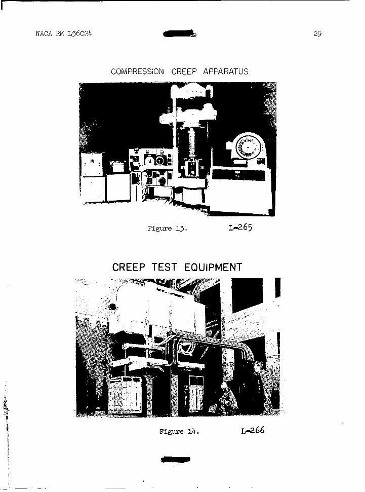
Figure 13 i s a photograph of some compression creep apparatus i n ,,,,
the Structures Research Laboratory at Langley. This apparatus combines . '
a tes t ing machine with a furnace for the purpose of investigating the strength and creep behavior of structural elements at elevated tempera- tu res . The pa r t i cu la r equipment in p l ace i n t he t e s t ing machine is a fixbure for conducting tests on plqtes, but other f ixtures can be placed i n t h e machine for invest igat ing mater ia l propert ies or the s t ruc tura l behavior of columns and stiffened panels. The apparatus in the picture consists of a t e s t i n g machine, specimen fixtures, data recording appa- .:
ratus, furnace, and furnace control equipment. This particular furnace ' ,
has a temperature limit of 600°, corresponding t o a Mach number of about 3.0, but w i l l be soon rebuilt to extend the temperature l i m i t t o 1,200' which corresponds t o Mach number of about 4.0. Several other '- pieces of equipment similar t o t h a t shown here are available. in the , #
structures laboratory for determining the elevated temperature strength B and creep properties of materials a t temperatures up t o about 1,800~. Metals are unsuitable for structural applications at this temperature 3: which corresponds t o a Mach number of about 5.0. $
Figure 1 4 shows a large furnace that was b u i l t f o r t h e purpose of if t e s t ing s t ruc tu ra l components such as box beams. The particular furnace # is 3 f ee t by 3 f e e t by 8 f e e t i n s i z e and has a temperature limit of 9 about gooo. In the se tup i l lus t ra ted the specimen is carrying a dead & weight load and i s undergoing a creep t e s t . By substi tuting hydraulic :.,
jacks for the dead weights, s ta t ic s t rength tests can be conducted i n this furnace.
' X
,$
I, A .
,* *I
mmF

NACA RM ~36~24 9
Equipment of the type i l lustrated in the previous two f igures i s used to invest igate the s t rength and creep character is t ics of materials and structures at elevated temperatures. One of the primary objects of these investigations has been the correlat ion of structural behavior with material behavior. This work has been fa i r ly successfu l and the strength of plates, st iffened panels, and box beams of many materials a t room and elevated temperatures has been correlated with the material stress-strain curves obtained under similar exposure t o temperature. Similar efforts have been made t o correlate the creep behavior of plates with mater ia l creep curves and t h e i n i t i a l e f f o r t s i n t h i s r e g a r d have also been successful.
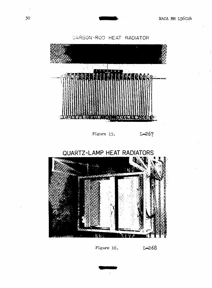
Turning now to considerations of rapid-heating equipment, there a re many techniques that can be used to rap id ly hea t s t ruc tures , bu t the par t icu lar method used in the Structures Research Laboratory of the NACA i s the radiant-heating technique. Two types of radiator are in use, the carbon-rod type and the quartz-lamp type.
Figure 15 i s a photograph of a carbon-rod heat radiator. This radiator consis ts of an array of 3/8-inch-diameter carbon rods that are 20 inches long and spaced 1 inch apart t o give a total length of 48 inches. These rods are brought t o incandescence by passing electrical current through them and the heat radiated i s used to rapidly heat a s t ructural specimen. This radiator has heated specimens a E rapidly as 100 Btu/ft2/sec,. This heating rate is higher than any r a t e contemplated f o r a i r c r a f t i n t h e speed range up t o Mach number 4.0 and is suff ic ient ly high to handle most of the problems associated with glide rockets in the higher speed range. It i s not capable of generating the heat fluxes produced by re-entry of ba l l i s t i c mi s s i l e s . It may also be used t o simulate the heat radiated by nuclear explosions.
The maximum power output of t h i s 2- by 4-foot array of carbon rods requires 2,000 kw of e l e c t r i c a l energy. The power requirements of rapid- heating equipment are thus quite high and special power sources are nec- essary wherever they are used. Init ially only 225 kw were ava i l ab le i n Structures Research Laboratory, but t h i s has recently been increased to 2,000 kw and a budget request has been in i t ia ted for a capac i ty of 10,000 kw. This lat ter power supply w i l l permit the construction and operation of radiant heaters that can heat both sides of s t ructures as large as 6 by 8 f e e t .
The carbon rods have a high thermal inertia and about 12 seconds is required to bring them to their operating temperatures of 4,600' F. Con- sequently, the control of the heat output from th is type of heater is ra ther - , .d i f f icu l t . In most invest igat ions in which these radiators are used, a mechanically operated shield i s needed to control the heat ing of the specimen. This kind of control usually provides only a single-step input and is not very suitable for simulation of aerodynamic heating. A more desirable radiator could be control led e lectr ical ly to give a varying heating rate. The quartz-lamp heat radiator i s one that f u l f i l l s t h i s requirement . -

10
. . .
In t h e i n i t i a l developnent of radiant heaters considerable effort j ' .
was devoted to tungsten f i lament types such as indus t r i a l heat lamps and ;.-
it was found that the General Electric Company was actively developing a tubular quartz lamp that very nearly fulf i l led our requirements. Development work with the General Electric Company resu l ted in the lo - inch: quartz lamp. This lamp consis ts of a tungsten filament encased i n a 3/8-inch quartz tube f i l l ed with an inert gas. This particular lamp is '.:,ih r a t e d a t 1 kw and 2.20 v, but is frequently used for high intensity heating' , a t 460 v and 3 kw. Recently, lamps have become ava i l ab le i n t he 25-inch length which operates on 460 v f o r continuous use or which can be operated a t twice this vol tage for short h igh intensi ty heat ing tes ts . A 50-inch lamp is a l so under development and should be available soon. The tungsten fi lament in these lamps has low thermal inertia and consequently when com- bined with proper control equipment can give varying heat intensit ies.
. ,
. .
Figure 16 i s a photograph of a quartz-lamp radiator . This pa r t i c - ular setup shows two 10- by 24-inch radiators heating each side of a s t ruc tura l specimen. Each radiator consis ts of a double-deck array of quartz lamps t h a t are spaced at l /2-inch intervals. There are 97 lamps ; i n t h e 24-inch radiator , and a t maximum intensity they require approxi- mately 300 kw of power. In an array such as t h i s t h e quartz-lamp radi- ~j
a to r can provide maximum heating rates approaching the 100 Btu/ft2/sec ;''.
obtainable with the carbon-rod radiators. This appears to be about the ; ' ' prac t ica l upper limit for these particular quastz lamps, but further . I
development can lead t o higher power densit ies; for example, a 23-inch _-I
lamp r a t e d a t 3 kw a t 600 vol t s has been produced. Further development ': can also increase the maximum in tens i ty of carbon-rod radiators .
Figure 17 shows some of the types of t e s t s made with the rapid- heating equipment. The s t ruc tu ra l specimen i s heated by radiant heaters and may be simultaneously loaded by some type of t e s t ing machine or loading apparatus as indicated in the sketch, the purpose of these tests then being to inves t iga te the e f fec ts of rapid heating alone, o r the combined e f f ec t s of rapid heating with static o r dynamic loads, on s t ruc- ,,
t u r a l behavior. For example, items that are being investigated include the thermal buckling and maximum strength of s t ructures for var ious com- binations of loads and rapid heating and the e f fec t of rapid heating on F the natural frequencies of vibrat ion of a s t ruc tu re t o determine how ,j$
rapid heating influences the effective st iffness of a s t ructure . Also, of interest are thermal deformations of the s t ructure which may occur 4'
ei ther with o r without applied loads. These deformations may a l so be e*> i in te rpre ted in terms of reduced s t i f fnes s of a s t ructure .
Figure 18 i l l u s t r a t e s some of the types of construction that have ,!k .I, been included i n such test programs. The purpose of these investigations I.',
iiP
3P
ti
! .F $ 1.

NACA RM ~ 5 6 ~ 2 4 11
i s t o determine the characteristics of existing types of construction under rapid-heating conditions as well as t o develop new types of con- s t ruct ion that are less susceptible to the detrimental effects of rapid heating. Thus the t e s t program has included both the mulitweb structure with formed channel webs and the skin stringer type of construction which are representative of current practice. Also investigated have been the corrugated web and a truss-type web which have low extensional s t i f fness and consequently induce negligible thermal stresses in a rapidly heated s t ructure . These types of construction have been investigated, both for their thermal s t ress propert ies and for their load-carrying capabi l i t ies . Other types of structures investigated include integrally st iffened con- s t ruct ion and the honeycomb core which are promising means of s tab i - l iz ing the skin of high-speeii vehicles. Both of these constructions have been investigated on some wing models t e s t e d i n a supersonic jet and both constructions were superior t o more conventional designs that had d i f f i - culty surviving the test conditions.
Figure 19 i s an i l l u s t r a t i o n of one setup in which the e f fec ts of rapid heating on the character is t ics of some box beams were investigated. The box beams included the formed channel, corrugated, and truss-type webs. Each cover of the box beams was heated by the carbon-rod radiators shown above and below the specimen and a pure bending moment was applied through the loading f ixture at the end. This is a re la t ive ly simple type of combined heating and loading setup i n which the heating and loading are gross simulations of the heat and loads expected i n f l i g h t .
Figure 20 shows a more complicated arrangement for heating and loading a missile w i n g . This setup uses quartz lamps and numerous load points in an effor t t o simulate more accurately the distribution of heat and load. Although the photograph does not show the auxi l iary control equipment it i s evident that detailed simulation requires very complex arrangements of tes t apparatus . It i s thus desirable to have some type of f a c i l i t y i n which proper simulation can be obtained without the complexity exhibited here. One such f a c i l i t y i s a heated wind tunnel in which the structure can be both heated and loaded aerodynamically.
Figure 21 shows a wing model se tup in the p ref l igh t j e t at Wallops Island, Va. , f o r t h e purpose of conducting an aerodynamic heat ing tes t . The NACA has previously reported much of the work that has been done i n t h i s f a c i l i t y i n which small wing models have been subjected to aerody- namic heating and loads with the results that several models have experi- enced dynamic f a i lu re s as a resu l t of the rapid-heating combined with aerodynamic loads.

12 NACA RM ~ 5 6 ~ 2 4
High-Temperature Structural Research Laboratory
In 1951 it appeared that the requirements for high-temperature struc- tural research were increasing substantially and that the NACA would need a l a r g e f a c i l i t y i n which such problems could be investigated. The prob- lem of conducting such research was studied during the following year and the requirements indicated on f igure 22 were e s t a b l i s h e d f o r t h i s f a c i l i t y . In general, it was r equ i r ed t ha t t he f ac i l i t y be able t o simulate the heating and loading encountered by high-speed a i r c r a f t and that r e a l i s t i c strucliural models be accommodated. With regard to the heat ing, it was necessary that the faci l i ty s imulate both the magnitude and d is t r ibu t ion of the heating. This means that it must e i ther heat the model aerodynam- i c a l l y as i n f l i g h t or provide some very elaborate control equipment f o r duplicating the temperatures and heating rates experienced i n f l i g h t . With regard to the loading, again it was desirable that t h e f a c i l i t y sim- ulate both the magnitude and d is t r ibu t ion of the expected loads and that the loads could be applied in the manner expected in f l i gh t , i . e . , t he structure would be subjected to rapid applications of load at various times during the heating cycle. Since the exact nature of the environment on the s t ructure was not known at that time and is a t best only generally understood at present, the conclusion was reached that the only good solu- t i on t o t h i s f a c i l i t y problem was a very special type of wind tunnel i n which the heating and loading would be produced aerodynamically a s i n f l i g h t . It must be a special type of wind tunnel t o provide true stag- nation temperatures and heat-transfer rates. The design conditions selec- ted covered Mach numbers up t o and including 3.0, which was bel ieved to be the probable speed range of man-carrying aircraf t dur ing the t ime this ' f a c i l i t y would be of most use.
The s ize of t h e f a c i l i t y was determined by the s t ruc tu ra l models it was d e s i r e d t o t e s t . The model c r i t e r i a were that t h e f a c i l i t y should accommodate s t ruc tu ra l components such as wings, bodies, or control sur- f aces l i ke ly t o be used on high-speed a i r c r a f t and that these models would be of the same type of contruction as the fu l l - s i ze a r t i c l e . The a b i l i t y t o construct buil t-up structural models f i x e s a minimum s i ze fo r t he models and consequently determines the size of t he t e s t s ec t ion . Also, the con- d i t ions produced in the tunnel must take proper cognizance of the scaling laws associated with aerodynamic heating and loading o f s t ruc tura l models and the s t r a in d i s t r ibu t ions that result . Since the various phenomena . .
under invest igat ion scale in different ways it w a s concluded that the ..
f a c i l i t y should be as large as possible in order that the models be near ' f u l l scale. Large supersonic wind tunnels, however, are very expensive so t h e f i n a l compromise was a tes t sec t ion measuring 6 fee t in he ight by
82 feet in width. This s i ze can accommodate half-scale models of many '. 4 s t ruc tura l components of fu ture a i rc raf t or complete missiles.

NACA RM ~ 5 6 ~ 2 4 0 13
Figure 23 shows the operating range of t h i s f a c i l i t y . S t a t i c p r e s - sure in the t es t sec t ion i s plotted as a function of Mach number and the shaded area indicates the combinations of pressure and Mach number avai l - able. For reasons t o be d iscussed shor t ly , th i s fac i l i ty w i l l be a blowdown-type tunnel, thus the approximate running times i n seconds are indicated for various conditions. The Mach number range extends from 1.3 t o 3.0, a l though v i r tua l ly a l l t es t ing w i l l be i n t h e Mach number 2.0 t o 3.0 range. The stagnation temperature i s fixed at 660° F, the actual value experienced in the s t ra tosphere a t Mach number 3.0. Stagnation temperature cannot be varied during a run, but can be p re se t a t any desired value between about 100' F and 660° F. On the r ight of the chart the pressure has been interpreted in terms of a l t i t u d e f o r a half-scale model. To get the correct temperature dis t r ibut ion in a scale model of a structure, the scale model must be heated fas ter than the ful l -scale a r t i c l e . Consequently, i n t h e wind tunnel the half-scale model must be run a t higher densities than a fu l l - sca le a r t ic le to ob ta in the cor rec t Reynolds number and thus correct heat-transfer coefficient. The a l t i t ude scale indicates the ful l -scale a l t i tude for a half-scale model and shows that at Mach number 3.0 the running conditions simulate the heating encountered in t he a l t i t ude range between 40,000 t o 50,000 f ee t , whereas at Mach number 2.0 the alt i tudes simulated are from 10,000 t o 35,000 f e e t . In the t es t of a half-scale model t ha t i s heated faster to provide the proper temperature distribution, significant events occur faster (by the square of sca le fac tor ) so that the running time in the tunnel corresponds t o 4 t imes the t ime during full-scale f l ight, thus a 30-second t e s t of a half-scale model w i l l produce the temperatures encountered by t h e f u l l - s c a l e a r t i c l e i n a 2-minute f l i g h t . A s previously indicated, this f a c i l - i t y i s a blowdown-type tunnel. It w i l l be a blowdown wind tunnel p r i - marily because of the tremendous amount of power required for the con- tinuous operation of such a f a c i l i t y . For example, the maximum power required is a t Mach number 2.5 on the upper curve. A t this condition the
tunnel would require 3- million horsepower for continuous operation.
However, by using a blowdown tunnel a 20,000-horsepower compressor running for l ess than 2 hours w i l l s to re suf f ic ien t air t o give the running times shown on the f igure. It may be of i n t e re s t t o no te that t h e t e s t con- dit ions indicated can be obtained without a subsonic diffuser. The super- sonic discharge is thus a gigant ic je t engine that has a maximum th rus t of about 750,000 pounds.
1 2
Figure 24 shows an a rch i tec t ' s ske tch of t h e f a c i l i t y which gives an indication of the s i z e and arrangement. The air is s tored in the b o t t l e s t o t h e l e f t which are approximately 70 feet h igh. The test sec- t i o n is housed in t he tallest section and the tunnel discharges through the opening indicated at the r ight . The tunnel controls and data recording equipment 'are housed i n the conc'rete building in front of t h e t e s t chamber and the other small building houses equipment for stagnation temperature control. -

1 4 NACA RM ~ 5 6 ~ 2 4
Figure 25 i l lus t ra tes the genera l arrangement of t h e f a c i l i t y . The air storage field, pressure control valves, heat accumulator, supersonic nozzle, and test sect ion are indicated in black, the stagnation temper- ature controls in gray, and auxi l iary equipment in dark gray. The heat !
accumulator which f i x e s the stagnation temperature of t he air before it is expanded through the nozzle i s a regenerative-type heater that s tores hea t in th in s ta in less s tee l shee ts between runs and then trans- f e r s t h i s h e a t t o t h e a i r s t r e a m during t h e t e s t . There are approximately 600,000 pounds of 0.025-inch-thick stainless steel s h e e t i n t h i s accumulator.
Figure 26 shows a cross-sectional view of the nozzle and tes t sec- t i o n of t h i s f a c i l i t y . This particular nozzle shown is one that pro- duces a Mach number 3.0 air flow and a schematic model i s shown in t he tes t sec t ion . The nozzle walls are f lexible plates pul led down against templates. By changing templates the Mach number can be changed. Three s e t s of templates are being made t o give Mach numbers of 2.0, 2.5, and 3.0. A s i l lus t ra ted here , models may be mounted i n t h e f l o o r of the t es t sec- t i o n on a turntable which controls the angle of a t tack and thus the aero- dynamic loads on the model. This turntable i s actuated by a hydraulic system controlled by a servo. The angle of a t tack can be programmed during a t e s t so that the model experiences pull-ups o r similar load applications. Other arrangements of models include bodies o r complete missiles sting-mounted in the cen ter of the tunnel.
Since th i s tunnel dupl ica tes the aerodynamic heating experienced by aircraf t s t ructures , the tunnel i tsel f experiences the same heat ing in the tes t sect ion, but in the nozzle throat where the flow i s very dense the tunnel experiences more severe heating than any model expected t o be pu t i n it. Consequently, one of the problems t o be investigated in the f a c i l i t y i s also involved in i t s design. A t the throat , the f lexible p la tes which a re 1 inches thick steel could experience very rapid
heating and consequently high thermal stresses. These stresses could be high enough t o permanently deform the plate; thus it was necessary t o devise some means of protecting the nozzle walls from the severe heating. Since the maximum temperatures expected i n t h i s t u n n e l a r e moderate, a prac t ica l approach w a s to insulate the tunnel wal ls in the area between the entrance cone and the t es t sec t ion . Numerous means of insulating the w a l l s were investigated and the f ina l so lu t ion w a s t o use a phenolic fiberglas laminate 0.050 inch thick. This laminate i s a suff ic ient ly poor conductor of hea t t o keep the s t ee l p l a t e below 2000 F i n any con- templated run.
e.
x
The type of t e s t program planned for t h i s f a c i l i t y will include rapid aerodynamic heating of various types of structures such as wings '.:# and fuselages that incorporate both conventional structures and s t ruc tures , , specifically designed to al leviate thermal stress. In addi t ion to the : heating, the structure w i l l be subjected to aerodynamic loading . .
. .
, .
1 -

NACA RM ~ 5 6 ~ 2 4 15
during the heating cycle t o determine combined e f f ec t s of heating and loading and t o investigate any aero-elast ic o r f l u t t e r problems that may be encountered.
This f a c i l i t y i s now under construction with a l l major components under contract . The foundations are nearing completion and the erection of buildings and equipment w i l l begin soon. The tunnel should begin operat ing in la te 1956.
Concluding Remarks f o r Lower Mach Number Region
This concludes the discussion of our accomplishments i n t h e f i e l d s of aerodynamic heating and s t ructural design in the speed range up t o Mach number 4.0. In addition, some plans for future research have been indicated. Although much has been accomplished already, the existing problems are s o numerous that a much grea te r e f for t i s needed t o e s t a b l i s h the character is t ics of the environment, f ind means to a l l ev ia t e t he severi ty of aerodynamic heating, establish the range of usefulness of present methods of structural design, and to devise new types of con- s t ruct ion that are not susceptible to the detrimental effect of aerody- nami c heating .
The remainder of the discussion w i l l be devoted t o f a c i l i t i e s f o r research in the higher speed ranges.
FACILITIES FOR HYPERSONIC REGION
Environment
The discussion for lower Mach number began with a discussion of environment, f igure 27 extends that discussion to higher speeds. The temperatures, pressures, and ve loc i t ies a re the same as those previously discussed except that the values are higher for the hypersonic speeds. The temperatures a t these speeds, referring back t o f igure 1, went up t o that of the sun's surface and more. Now, granted that these extreme tem- peratures may not exis t as one normally thinks of temperature, but when the air is compressed on a body moving through it, the energy is cer ta inly there . It may appear as dissociation, ionization, other molecular degrees of freedom, etc. , but the high energy level exists.
A t these temperatures (and even a t lower values) chemistry enters the picture. One example of this chemical entry is the proposal that re-entry bodies be cooled (or absorb heat) by allowing the outer layer of s t e e l t o melt and slough off. This condition has been simulated i n low-temperature wind-tunnel t e s t s by m a k i n g models of Wood's metal and

16 NACA RM ~ 5 6 ~ 2 4
melting them w i t h aerodynamic heating. In an attempt t o g e t more real- i s t ic condi t ions some tests were made with preheated steel rod specimens i n t h e TOO0 F, M = 2 p re f l igh t j e t a t Wallops Island, Va.
Carbon and chrome-molybdenum s t ee l s burned rather than melted when inser ted into the j e t a f t e r being preheated t o about 2,400° F; s ta in less s t e e l and copper did not burn. Under the tes t conditions the air je t actually tended t o c o o l t h e specimen and also the Mach number was low enough tha t the air w a s not dissociated or ionized. Under more r e a l con- di t ions where the air w i l l be heating the metal rather than cooling it and where the air , through i t s temperature, dissociation, and ionization, may have considerably increased chemical activity the stainless steel and copper may also burn.
In order to avoid the preheating requirements and t o obtain more nearly correct aerodynamic heating, the Ames Laboratory built a hot subsonic j e t using acetylene burners to get temperatures of about 2,6000 F. Some exploratory tes ts were made of two s t e e l models i n t h i s j e t . The models were 3/8 inch in diameter - one was sharp pointed and one had the nose blunted to a 1/16-ir~ch radius. The pointed body came up t o temperature very quickly and burned. The greater heat capacity of the blunted nose protected it at these temperatures but from the glow it appeared t h a t it too would burn i n a somewhat hotter airstream.
In some o t h e r t e s t s a heated s t r ip of t i tanium alloy burned very n i ce ly i n a s t i l l nitrogen atmosphere - so oxidation i s not the only chem- i c a l a c t i v i t y of concern. It appears in general that chemistry is t o be a r e a l p a r t of the high-speed structural environment. It i s believed that the aerodynamics and materials aspects of the problem are pointing toward a merging of t h e f i e l d s of structures, aerodynamics, metallurgy, and chem- istry in high-temperature structural research and design.
S t ruc tura l Research Equipment
Having considered the environment for the higher Mach number range, consideration may now be given t o the equipment t h a t may be needed f o r research in this range. Figure 28 shows a l i s t i n g of some of t h i s equip- *
ment, and, although a t first glance, it appears primarily to be aerodynamfc rather than structural , the f igure i s not mislabeled. The asterisks indi-. cate those items tha t a re ac t ive ly producing data of in te res t t o t h i s f i e l d . The other items represent ideas that are being studied in efforts to learn" what can be done to ge t the requi red da ta .
The items are broken down a rb i t r a r i l y i n to three groups: Ground, Flight, and Combination. Each item w i l l be d iscussed br ie f ly bu t f i r s t :
it i s important t o re-emphasize that the unstarred items are in the explor- a tory , planning, or small-scale laboratory study stage.

Supersonic true-temperature tunnels.- By "supersonic true-temperature tunnels" (figure 28) are meant those i n which the air i s heated (usually by metallic heat exchangers) so that after being expanded through the supersonic nozzle the static temperature is representative of t he atmos- phere or stratosphere, that i s between f70° F rather than a t -300 or -400' F. Most supersonic tunnels are heated only enough t o prevent moisture condensation or a i r l iquefac t ion in the test section. But a f e w , l ike the p re- f l igh t j e t a t Wallops, the new large s t ructures je t at Langley and some other small j e t s now being bui l t , are heated sufficiently to pro- vide duplication of t rue air conditions. Enough i s believed t o be known at present to allow true-temperature tunnels t o be bui l t wi th s tagnat ion t e m - peratures up t o 1,800' t o 2,000° F which w i l l cover Mach numbers up t o near 5 . To go t o higher speeds, however, and s t i l l get the same quality of duplication of t rue environment as discussed for the new structures j e t a t Langley, other equipment will be needed. Some of the other items on figure 28 represent ideas being studied along these lines.
Ceramic heat exchangers.- Another possible means of heating the air i s t o use ceramics rather than metals in the heat exchangers. Figure 29 shows such a jet schematically and l ists the ceramics presently being considered f o r such use. The stagnation temperature w i l l be l imi t ed t o somewhat below the melting point of the ceramic - the l is ted melting points show the range we might be able t o cover, 3,400' F t o 5,900' F. Other problems, however, must also be considered, such as: Magnesia has a high vapor pressure and is subject to breaking up at high temperatures, and thor ia i s somewhat radioactive. In general quite a l o t i s known about ceramics but in par t icu lar enough i s not believed t o be yet known t o permit the straightforward design of even a 1-inch-diameter 3,000° F j e t . Con- sequently Langley i s now building a small laboratory-scale heat exchanger to e s t ab l i sh some design principles and determine just what might be a t ta in- ab le in terms of temperature, Mach number, and t e s t a l t i t u d e .
Special compressors.- Air can also be heated by rapid compression; thus consideration must be given "special compressors;" these include such equip- ment as the Apgs hypersonic gun tunnel ( f ig . 30) . This equipment consists of a long tube (20-mm inside diameter) containing air, a piston, and a powder charge. The powder is ignited and pushes the pis ton down the tube compressing the air; the valve i s then opened and the air is discharged through the hy-personic nozzle. The a i r i s heated by the compression and a l so by shock waves ( se t up by the pis ton motion) bouncing back and f o r t h . i n t he t ube . This equipment has been operated a t stagnation temperatures of over 6,000~ F, Mach number of approximately 7, t e s t a l t i t u d e of 100,000 feet , f o r about 1 second. This sounds very good but the a i r under these conditions caused very bad erosion of the compression chamber, valve, and nozzle. As a r e su l t of t h i s t h e gun tunnel i s now being operated only a t temperatures up t o 2,000° F u n t i l more i s learned about how to -p ro tec t the equipment .

18 NACA RM ~ 5 6 ~ 2 4
The Langley Laboratory is building . a p i l o t model of ,an " isentropic" compressor that should be somewhat less subject to erosion but which w i l l a l so be l i m i t e d i n maximum temperature. In the isentropic compressor the pis ton is driven by air metered from another source so the pis ton motion is controlled and w i l l not set up the bouncing shock>waves. This equip- ment w i l l be limited t o a maximum temperature of about 3,000° F i t s i n i t i a l ' operation and probably w i l l s t i l l have t o be i n the 2,0000 F range until more is learned about handling such hot high-pressure air. When more is learned about this the temperature ranges of both items can be increased by preheating the air i n t h e compression chamber.
Chemical j e t s . - Another potential source of hot high-energy gas streams for research work is the chemical je t . Figure 31 lists three poss ib i l i t i es , inc luding a i r . The chemical contents of the j e t s , it w i l l be noted, a re qu i te d i f fe ren t . The a i r j e t should retain i t s familiar 78-percent nitrogen, 21-percent oxygen, e t c . up t o a t l e a s t 5,000° F. The ethylene-air j e t has about the right nitrogen content but i s def ic ient i n oxygen and a l so has appreciable carbon and hydrogen compounds. The acid-ammonia rocket je t i s def ic ient in both ni t rogen and oqygen except that a t high temperatures the water vapor may t e n d t o a c t very much like f ree oxygen. A t any r a t e it is apparent from the listed values of pres- ently available maximum temperatures that high temperatures are easier to reach with chemical jets at present and f o r that reason Langley is building small models of such jets t o t r y t o determine how much effect the chemical differences cause and how much use can be made of the chemically incorrect jets.
Shock tubes.- Another item that may be considered a "special com- pressor" i s the shock tube. These a r e i n rather extensive use at various places for the study of gas properties a t high temperatures and they may prove quite useful as high-temperature aero-structures research equipment. A s shown on f igure 32, the shock tube consists of a high-pressure chamber, a diaphragm, a low-pressure chamber, and a w e a k s e a l at the end. I n oper- ation the high pressure i s b u i l t up t o a desired value, the diaphragm is broken, and the high-pressure gas drives a shock wave down through'the low-pressure chamber. This device w i l l then provide stagnation temper- a tures of 10,OOOo F o r over, Mach numbers up t o about 2.5, and t e s t alti-, tudes down t o sea l e v e l w i t h test durations of 1 t o 2 thousandths of a second. By inserting the entrance of a hypersonic nozzle in the low- pressure chamber, the Mach number can be increased to 10'or more at the expense of an i nc rease i n t e s t a l t i t ude t o abou t 100,000 f e e t . The extremely short test times available w i t h t h i s t ype of equipment present . ' ' tough instrumentation problems but s o far it is the only ground item that w i l l produce stagnation temperatures of the order of 10,OOOo F i n a moving air stream. Consequently, NACA i s working with p i l o t models to evaluate. . the u t i l i t y of the shock tube and t o develop research techniques for i t s use. Incidentally, the short test time should be helpful from the standpoint .:
of equipment protection requirements. 3 ,
. . . ". ._. ._ . . . . . - .

NACA RM ~56~24 - 19
FLunaces and radiators.- The ear l ier d iscussion covered the present s ta tus of furnace-and-radiator-type equipment and indicated our f a i r l y extensive use of such items. With presently available equipment, temper- atures over 5,000° F o r 6 , 0 0 0 ~ F will probably not be possible except with the sun furnace or the. high-intensity electric arc.
With a sun furnace, which is essent ia l ly a parabolic mirror f o r col lect ing the sun’s radiation and focusing it at one spot, it appears possible to get temperatures in the range from 6 , 5 0 0 ~ F t o 8 , 0 0 0 ~ F and heat fluxes of the order of 2,000 Btu/ft2/sec. Such a device would be extremely useful, particularly for some materials work. Convair i s using some small ones and a large one probably should be built; at present, however, the NACA has no such plans.
The high-intensi ty e lectr ic arc offers the poss ib i l i ty of achieving temperatures somewhat higher than the sun furnace and NACA i s investigating it t o see ju s t w h a t u t i l i t y it might have.
In general, furnaces and radiators are l imited by the lack of airflow. For some uses this can be overcome by using them to hea t models mounted i n cooler a i r j e t s . By t h i s means, it i s poss ib le to ge t an approximately correct temperature distribution but the heating w i l l be incorrect; i .e. , the air w i l l be cooling the model rather than heating it and the nose w i l l undergo the greatest cooling rather than the greatest heating. This scheme i s useful, however, and i s being exploited where applicable.
1 2 . - The last i t e m of purely gound equipment l isted in f igure 28 is t h e a s y e t m o w n idea l for which a search i s now being made, Since none of the items already discussed w i l l allow true duplication Of all the con- di t ions in the higher speed range.
Project i les and combination equipment.- Figure 28 l i s t s three items of flikt equipment. In order of speeds a t t a i n e d t o date: pro jec t i les - are the fastest and airplqnes are the slowest; as fo r s i ze and tes t dura- t ion the order i s reversed, airplanes are the la rges t and have the longest time of f l i g h t and pro jec t i les are the smallest and have the shortest f l i g h t time .
”
Project i les , despi te the instrumentation troubles caused by t h e i r small s ize and shor t f l i gh t times, do offer considerable promise as research tools. Although some work has been done with fragments from shaped charges and similar explosives the fastest f l i g h t s of pro jec t i les of known, predetermined, shape and s ize have been made with the Ames light-gas gun i l l u s t r a t e d on f igure 33. This gun consists of a powder chamber, piston, helium compression chamber, seal, model, and evacuated bar re l . The powder i s ignited, the piston compresses the helium, which i n turn shears the seal and drives the model out through the evacuated

20 0 NACA RM ~ 5 6 ~ 2 4
ba r re l . A 0 .22-cal iber pi lot model i s i n use a t Ames and has provided. projecti le speeds of over 15,000 fps . With a la rger (20 mm) .gun now i n the design and construction stage it is believed that speeds approaching 20,000 fps w i l l be obtained. This equipment w i l l then provide stagnation temperatures of over 25,000' F and ef fec t ive t es t a l t i tudes ranging from sea level on up s ince gun launched project i les can be f i red in to p res - . surized ranges with controlled atmospheres.
Lower-speed p ro jec t i l e s f i r ed from powder guns can also provide use- f u l information; some work along this l i n e is being done a t both Ames and Langley, but the most highly developed use of such guns has been i n t h e Ames supersonic free-fl ight tunnel. This tunnel i s i l l u s t r a t e d i n t h e top of f igure 34. Here the model is f i r e d upstream into a long, constant Mach number, test section of a supersonic tunnel. The tunnel air speed and project i le veloci ty are addi t ive thus giving higher veloci t ies than either.device alone could give. In addition the major par t of the stag- nation temperature comes from the projecti le kinetic energy so the tunnel i s not required to handle such hot air. This equipment has been used exten- s ively to s tudy the factors affect ing boundary layers at high speeds which are important because of the factor of 10 in the d i f fe rence between lami- nar and turbulent boundary-layer heating.
On the lower part of f igure 34 i s i l l u s t r a t e d a "re-entry tunnel" t ha t i s somewhat k in to the f ree- f l igh t tunnel . Here the t es t sec t ion i s a long supersonic nozzle shaped so that the a i r densi ty var ies a long the nozzle in the same exponential fashion that it varies with alt i tude i n f r e e a i r . Thus a model f i r e d upstream into this nozzle will undergo the same increasing density that a re-entry body undergoes i n coming down tkrough the atmosphere. The scaling laws, as far as i s now known, are such tha t t he combination of small size, short test t ime, and den- s i ty cont ro l in the tunnel can be arranged t o give good simulation of the rea l problem. In order to evaluate this scheme Ames i s building a small p i lot model re-entry tunnel to use with the 0.22-caliber l ight- gas gun. If present expectations are realized, naturally efforts w i l l be made to design a larger tunnel t o use with the larger light-gas gun.
Rocket models. - Now t o r e t u r n t o t h e f l i g h t equipment: f igure 6 ..
covered the rocket-model program fa i r ly wel l . S ince th i s is the on ly w a y known a t p re sen t fo r really get t ing t rue dupl icat ion a t the high speed with instrumented articles, NACA i s in the p rocess of extending these tests t o higher speeds as rapidly as rocket-motor and instrumentation limits w i l l allow. For an i l l u s t r a t ion of the range of tes t condi t ions that can be covered, some typical rocket model t ra jec tor ies a re shown on f ig - ure 35. Here a re p lo ts of alt i tude against range for three types of rocket f l ight plan. The solid portions of the l ines indicate powered f l i g h t and the dashed portions show coast ing f l ight . The maximum speed, of course, i s a t t h e end of t he l a s t so l id l i ne . The straight-away t ra jec tory i s the simplest and provides the highest speeds in general

NACA RM ~ 5 6 ~ 2 4 L 21
f o r a given propulsion system; however, it has the disadvantage of placing the data-gathering portion of t h e f l i g h t a t very high alt i tude which increases the instrumentation problems, a l so the models go t o extreme ranges (500 or 600 nautical miles) which requires a long range sea search or clearance. The N a v y , incidentally, has been most cooper- a t i v e i n making these sea searches for us and i n moving the i r t r a in ing f l ee t ou t of the area on f i r ing da tes . To avoid or lessen some of these problems, p lans a t Langley a r e t o use the re-entry type trajectory where the maximum speed i s obtained on the way down a f t e r t he model and par t of the booster system have coasted over the peak of the t ra jec tory a t lower speeds. A s noted on the f igure, the Lewis Laboratory i s Using a similar fl ight plan with their air-launched models.
Airplanes. - The NACA i s planning t o extend the X-1 and work men- t ioned earlier into the hypersonic range with a new research airplane. This airplane i s designed t o operate a t Mach numbers up t o near 7 over an a l t i tude range of several hundred thousand f e e t . An envelope of design f l igh t a l t i tude aga ins t Mach number fo r such an airplane i s shown on f ig- ure 36. With present knowledge, use of the full a l t i t ude po ten t i a l i t i e s of t he a i r c ra f t will probably be impossible because of heating during re-entry but such an airplane will allow detailed measurements of the mag- nitude and d is t r ibu t ion of heating rates, temperatures, stresses, deforma- tions, airloads, etc., and most important will provide operating experience i n t h i s speed range with the actual full-size aircraft .
Equipment Summary
TO summarize br ief ly , f igure 28 i s again referred to. In order t o pro- vide data in the h igher speed range with any of t h e l i s t e d items of equipment, or with whatever new ideas t h a t may arise, a considerable e f f o r t w i l l be needed i n obtaining operating experience and i n developing research techniques and instrumentation.
True-temperature tunnels probably can be made t o operate up t o t h e range of 6,0000 F or 7,000° F sometime in the fu ture , i f the materials problem of containing and directing the required hot high-pressure air can be overcome.
Chemical j e t s w i l l allow a temperature range o f , 5,000° F t o 6,0000 F t o be reached sooner and more easi ly but the effects of gas composition and chemistry on the results obtained need more study and evaluation.
Shock tubes, despite their short tes t times, w i l l provide temper- atures up. i n t h e 10,OOOo F range and should prove quite useful.
Furnaces and radiators offer the possibi l i ty of reaching temper- atures of from 6,000' F t o . 8,000' F. The high-intensity arc, which may -

22 NACA RM ~ 5 6 ~ 2 4
go higher i n temperature, needs more study at present. This general type of equipment should prove quite useful for materials work and either alone o r when combined with cooler air jets ' w i l l be use fu l fo r ac tua l s t ructural research.
Rocket models and airplanes are the only presently known items that w i l l provide complete true duplication of the whole environment. Rocket models need more e f f o r t on rocket-motor and instrumentation development and f o r airplanes, naturally, a t least gross answers must be obtained t o some of the problems before even research airplanes can be designed and b u i l t .
Project i les and the special combination tunnels should prove extremely valuable despite their size l imitat ions.
CONCLUDING REMARKS
In conclusion, the following general observations can be made:
The f i e lds of s t ructures , aerodynamics, metallurgy, and chemistry appear t o be merging rapidly and a l l are becoming in tegra l par t s of the f i e l d of high-temperature structures.
Actually none of t he ground equipment discussed provides com- p le te ly adequate duplication or simulation of flight conditions but it i s f e l t t h a t each item can contribute some answers t o the whole problem.
With respec t to s ta tus of research equipment, where the way i s known facil i t ies are being provided and where knowledge i s limited, work i s progressing a t laboratory scale to learn what t o do. NACA i s giving the bes t poss ib le a t ten t ion to f l igh t work and, although it is too ear ly t o say what ground equipment i s needed, the needs are believed to cover A
the whole temperature range.
Langley Aeronautical Laboratory, National Advisory Committee for Aeronautics,
Langley Field, V a . , September 11, 1955.

50,000-
10,000-
5,000
To F
1,000
500
looo
i
i
".
t ( *
5 10 15 20 M
~
Figure 1. 6 2 5 4
HEATING RATES
4°K - " X A T (TURBULENT) 5 / 7
I $000 cc
-~ BTU/SEG F T ~ IOU :... TURBULENT
Figure 2. E.253 i

NACA m ~ 5 6 ~ 2 4
SPEED REQUIREMENTS
20 i?' ATLAS I
ATTAINED BY NACA 8 ,.-I PLANNED FOR
MODELS & AIRPLANES-! DESIGN
I
16 RESEARCH ROCKET r ' AIRCRAFT IN
12 '\, ' "AX 8 ~. cJ
HERMES NlKE I
X-2 NAVAHO#, I L. = - -* 4 &:*,,.-e
*@ 1945 1950 1955 1960
YEAR
0
Figure 3 . L-255
REGIONS OF INTEREST

ENVIRONMENT RESEARCH
TYPES
AERODYNAMIC LOADS AERODYNAMIC HEATING HEAT ALLEVIATION
FACILITIES
WIND TUNNELS AND JETS ROCKET MODELS RESEARCH AIRPLANES
Figure 5. L-2 57
AERODYNAMIC 'HEATING RESEARCH BODIES AND NOSE SHhkS WINGS AND FLAPS
<,".~,,"~,~ .>,-I "j - Q-ZJ a - 4 WING LEADING EDGES
CANOPIES a d ' /""7
? / / / / l j / l / / / / / / l / / f / l / / / /
,. I , , . . " "
~ " , . .~ n
, I . " , , . , , . ~
Figure 6. L-258

26 - NACA RM ~ 5 6 ~ 2 4
I I-IN. HYPERSONIC WIND TUNNEL
Figure 7. L-259
TRANSPIRATION COOLING TEST
Figure 8 . L-260
0

NACA RM ~ 5 6 ~ 2 4 c
, ROCKET MODEL AERODYNAMIC HEATING RESEARCH
Figure 9. L-261.
HYPERSONIC ROCKET MODELS
. . ',, ' !
I i
i
Figure 10. L-2 62

28 b, NACA RM L36C24
X-IB THERMOCOUPLE INSTALLATION . .. .
Figure 11.. ~ - 2 63
STRUCTURES RESEARCH TYPES
LOADS HIGH TEMPERATURES RAPID HEATING AERO- THERMO- ELASTICITY
FACILITIES
TESTING MACHINES OVENS AND FURNACES RADIANT HEATERS JETS AND WIND TUNNELS ROCKET MODELS RESEARCH AIRPLANES
Figure 12. L-264
I
NACA RM ~56~24
COMPRESSION CREEP APPARATUS
Figure 13. L-265 Figure 13. L-265
CREEP TEST EQUIPMENT
Figure 14. ~ - 2 6 6
NACA RM ~ 5 6 ~ 2 4
Figure 13. L-267
QUARTZ-LAMP HEAT RADIATORS
Figure 16. L-2 68

NACA FN ~ 5 6 ~ 2 4
RAPID HEATING TESTS THERMAL BUCKLING MAXIMUM STRENGTH
AT HEAT
NATURAL FREQUENCY THERMAL DEFORMATION EFFECTIVE STIFFNESS REDUCED STIFFNESS
AT AT
Figure 1'7. L-2 69
TYPES OF CONSTRUCTION
, . , Figure 18. ~ - 2 7 0

- . "
NACA RM ~ 5 6 ~ 2 4
HEATING AND LOADING OF -BOX BEAM
Figure 19.
HEATING & LOADING MISSILE WING
Figure 20. L-272

I
NACA RM L56C24
JET TEST OF WING STRUCTURE
Figure 21. L-273
BASIC REQUIREMENTS HIGH TEMPERATURE STRUCTURAL RESEARCH LABORATORY
SI MULATE HEATlN G MAGNITUDE DISTRIBUTION
SIMULATE LOAD1 N G MAGNITUDE DISTRIBUTION APPLICATION
ACCOMODATE STRUCTURAL MODELS CONFIGURATION CONSTRUCTION SCALING
Figure 22. L-274
33

34 NACA IIM L56C24
OPERATING RANGE. HIGH' TEMPERATURE STRUCTURAL RESEARCH LABORATORY
/ 14 C T A Chi rr tnulvATlON . TEMP.= 660"
j FT b
J 30 I
1.5 2.0 2.5 3.0
HIGH TEMP STRUCTURAL RES. LAB. " ,
, , >
" " . .
Figure 24. ~ - 2 7 6

NACA RM L36C24 35
GENERAL ARRANGEMENT HIGH TEMPERATURE STRUCTURAL RESEARCH LABORATORY
NOZZLE AND TEST SECTION HIGH TEMPERATURE STRUCTURAL RESEARCH
LABORATORY
*
Figure 26. -18
PrllE .~ . "

ATMOSPHERIC ENVIRONMENT
TEMPERATURE PRESSURE VELOCITY
CHEMICAL CONTENT CHEMICAL ACTIVITY
STRUCTURAL RESEARCH EQUIPMENT
SUPERSONIC TRUE-TEMPERATURE TUNNEL* CERAMIC HEAT EXCHANGERS SPECIAL COMPRESSORS
SHOCK TUBES FURNACES AND RADIATORS*
GROUND COMBUSTION PRODUCT TUNNEL
? ?
GUN- LAUNCHED PROJECTILES
AIRPLANES FLIGHT ROCKET MODELS
CoMBINATloN RE-ENTRY TUNNEL FREE-FL!GHT TUNNEL*
Figure 28. 1,481

NACA RM ~56~24 k 37
CERAMIC HEAT EXCHANGERS MATERIAL MELTING
POINT. OF
ALUMINA (Al203) 3450 CERAMIC HEATER
MAGNESIA (Me01 4750 AIR ZIRCONIA (Zr021 THORIA (Tho21 5970
TEST NOZZLE
STAGNATION TEMPERATURE - BELOW MELTING OF CERAMIC
MACH NUMBER - ? EFFECTIVE ALTITUDE - ?
Figure 29. 6 2 8 3
HYPERSONIC GUN TUNNEL
AIR, FVALVE
U) POWDER/ LPISTON CHARGE
STAGNATION TEMPERATURE - UP TO 6,000' F MACH NUMBER - 7
EFFECTIVE ALTITUDE - 100,000 .FT. DURATION - 1 SEC.
Figure 30. L-282

Icr NACA R" L56C24
CHEMICAL JETS AI R COMBUSTION ROCKET
(PURE) (ETHYLENE - AIR) (ACID -AMMONIA)
% % %
N2 70 N2 30.5 o2 p-J 21 og4 64.9
MISC. I I H z 0 0 7.5 Hz B 3.5
co2 0 7.5 OH I .7 CO,CZH, I .7 O2.NO.H I 4
PRESENT
TMAX. 2000°F 3400" F 4300°F
Figure 31. L-284
SHOCK TUBES
J ~ P H R A G M HIGH PRESSURE
OW PRESSURE WEAK
STAG. TEMP. - UP TO IO,OOO"F+ MACH NUMBER - UP TO 2.5 EFF. TEST ALT. - SEA LEVEL AND ABOVE DURATION - .OOl TO .002 SEC.
., . HYPERSONIC .. ' .. .. ... ., . ~ , ,, . .. i . '. ;. . .. ' :;: . . . TEST JET
STAG. TEMP - UP TO I0,OO- MACH NUMBER - UP TO 10' EFE TEST ALT - LI 100,000 FT. DURATION - .001 TO .002 SEC.
Figure 32. E285
I

LIGHT-GAS GUN POWDER CHARGE
STAG. TEMP. - UP TO 25,OOO"F.
MACH NUMBER- UP TO 15+
EFF. TEST ALT.-SEA LEVEL AND ABOVE
Figure 33. 1,4286
SUPERSONIC FREE-FLIGHT TUNNEL
.~
MODEL CATCHER
r AIR RE-ENTRY TUNNEL
CATCHER

40 - NACA RM ~ 5 6 ~ 2 4
200,000. '
ALT, FT
l00,000
ROCKET-MODEL TRAJECTORIES I
. .
4 I STRAIGHT AWAY,. i'
I (LANGLEY) I I ~
; ' :
I
.-RE-ENTRY TYPE
"" T4 :a 150.
RANGE, MlLES
Figure 35. ~4288
UTION OF STEADY
OPER. EXPER. WITH
0 2 4 6 8 M . ,
Figure 36. xi-289
NACA - Langley Field, VA.