na762tb - highpoint tech · na762tb overview ... b. double-click the “highpointiop.mpkg” icon...
TRANSCRIPT

HighPoint Technologies Inc. 1
NA762TB
High-Performance Thunderbolt™ Storage
User’s Guide
V1.00
Mar. 9, 2014

HighPoint Technologies Inc. 2
Table of Contents 1. Introduction ..................................................................................................................................... 3
2. SYSTEM REQUIREMENTS .................................................................................................................. 3
3. What’s in the Box? ........................................................................................................................... 3
4. NA762TB Overview .......................................................................................................................... 4
5. Setting up the NA762TB ................................................................................................................... 6
5.1 HDD Installation ......................................................................................................................... 6
5.2 Connecting the NA762TB to a Mac System. .............................................................................. 7
5.3 Install the software for NA762TB ............................................................................................... 7
6. Configuring RAID Arrays ................................................................................................................... 9
6.1 Configuring RAID Arrays ............................................................................................................. 9
6.2 Using the RAID disk with Mac OS X. ......................................................................................... 13
7. Deleting RAID Storage .................................................................................................................... 15
8. RAID Disk Failure Recovery ............................................................................................................ 15
9. Expanding RAID Storage Capacity .................................................................................................. 17
10. NA762TB Audible Alarm ................................................................................................................. 17
11. Technical Support........................................................................................................................... 18
12. LIMITED WARRANTY ...................................................................................................................... 18
APPENDIX A - Using the WebGUI (full guide) ........................................................................................ 19
APPENDIX B - Web RAID Management ICON Definition List ................................................................. 38
APPENDIX C - RAID Technology Explanation ......................................................................................... 40
APPENDIX D - Thunderbolt Daisy Chain configuration .......................................................................... 41
HighPoint Technologies Inc. 3
1. Introduction HighPoint's NA762TB Thunderbolt™ Storage Solution delivers high-performance, hardware RAID storage from a single cable connection!
The fully integrated hardware RAID controller and eight removable disk modules were designed for today's fastest 6 Gb/s storage devices - perfect for professional, I/O intensive applications such as digital content creation and media post production. The NA762TB's robust, stylish aluminum construction ensures your storage stays cool while running at optimum efficiency.
Key Features
Stylish, compact and Whisper-Quiet Enclosure Thunderbolt™ interface with 10Gbps of throughput in both channels Eight (3.5”) SAS/SATA Removable Disk Tray Module RAID level 0, 1, 10, 5, 6, 50, & JBOD Comprehensive Storage Management Suite Simplified Cabling Solution Temperature/fan failure LEDs and mutable buzzer alarm
2. SYSTEM REQUIREMENTS Apple Mac system with Thunderbolt support. Mac OS X 10.8.x or higher
3. What’s in the Box? A. NA762TB Enclosure x 1 B. Disk module x 8 (Installed) C. Thunderbolt™ cable x 1 (2 meters) D. Power Cord x 1 E. Hard Disk Drive mounting screw x 32 F. Key for HDD tray x 2

HighPoint Technologies Inc. 4
4. NA762TB Overview
Specifications
Host Interface :
• Thunderbolt™ • 10Gbps Bi-directional
Controller & RAID Feature :
• Supports RAID Level 0, 1, 10, 5, 6, 50, Single Disk or JBOD • Multiple RAID Selection • Online Array Roaming • Greater than 2TB Capacity per Disk Drive Support
Storage :
• Supports up to 8 SAS/SATA 3Gb/s or 6Gb/s 3.5" HDDs (Hard Disks Sold Separately) • Stylish Aluminum Housing with Solid Metal Structure • Thunderbolt™ Port for Daisy-chain up to 6 Devices • Individual Key lock of each HDD tray for physical security
Monitors/Indicators :
• Web base GUI RAID Manager for Remote Management • SMTP Support for Email Notification • FAN fail LED • Over Temperature LED • HDD fail LEDs
Cooling Fans:
• Two 80x 80x 25mm • Hot-Swappable

HighPoint Technologies Inc. 5
Power Supply:
• Server-grade 300W Single Power Supply • Low-noise Design • Universal: 100~240VAC, 50/60Hz
Environmental Requirements:
• Operation Temperature: 5°C ~ 50°C • Storage Temperature: -20°C~ 70°C • Operation Humidity: 10% ~ 80%, non-condensing • Storage Humidity: 5% ~ 95%
Dimensions :
• 231(D) x 156(W) x 365(H) mm • 9.1(D) x 6.1(W) x 14.4(H) inch
Operating System Support:
• Mac OS X 10.6.x/ 10.7.x/ 10.8.x /10.9.x (Driver was integrated by Apple OS X 10.9.x)
Scalability :
• Thunderbolt™ port for daisy-chain up to 6 devices
Panel Layout
1. HDD Power LED: White - Power On Indicator
2. HDD Status LED: Flash Blue - HDD Access Indicator, Red - HDD Failure Indicator
3. Power on LED: White - Enclosure power on
4. Fan Status LED: Normal - Green, Failure - Red (too slow RPM or stop)
5. Temperature LED: Normal - Green; Over-temperature - Red

HighPoint Technologies Inc. 6
6. Mute Button: Reset for Buzzer Beeping
7. Thunderbolt™ connectors:
Connecting Thunderbolt™ cables to host, upstream and downstream device
8. Hot-swappable cooling fans
9. Power cord receptacle
10. Power switch
5. Setting up the NA762TB
5.1 HDD Installation
The NA762TB has 8 Disk modules. It can support both SATA and SAS hard disk drives.
Note: Use only enterprise RAID edition series hard disks for RAID applications.
step 1. Place the NA762TB on a level surface and remove each disk module.
step 2. Carefully insert the HDD into each disk module and secure them with the provided mounting screws. Once complete, insert each disk module back into the front panel of the NA762TB.

HighPoint Technologies Inc. 7
5.2 Connecting the NA762TB to a Mac System.
step 1. Connect the NA762TB to the host system with the Thunderbolt™ cable, and then connect the NA762TB with a power source.
step 2. With the power cord connected to the power source, turn on the NA672TB using the power switch on the rear panel (switch to the “I” position to power on the NA762TB).
Note: The NA762TB is designed to be powered on and powered off simultaneously with the HOST system, when the NA762TB is connected to the HOST system with the Thunderbolt™ cable. Therefore, power on HOST first – the NA762TB will automatically power on. (NA762TB supports hot-plug and hot-unplug for powering-on and powering-off)
5.3 Install the software for NA762TB
1) Driver installation.
step 1. Driver Installation.
Please visit (http://www.hptmac.com/series_NA762TB-Resources.php) for the latest driver package. Once downloaded, unzip the package, and follow the procedure below:
a. Double-click the “uninstall.command” script file to uninstall the currently installed driver.
b. Double-click the “HighPointIOP.mpkg” icon to install the driver package. You will be asked to input the administrator’s password in order to complete this. Once

HighPoint Technologies Inc. 8
complete, you will be asked to reboot the system. Confirm the prompt to proceed.
step 2. Verifying driver installation.
After the driver has been installed and the system rebooted, verify the NA762TB device status using OS X System Information pane.
To verify the NA762TB driver status;
Click the Apple icon on top left of the screen, and select About This Mac, and then select More Info. Next, select System Report, and click PCI Cards on left side of the System Information pane. The Driver Installed entry for controller pci1103, 4520 should be “Yes”
2) RAID Management software installation.
All hard disks installed into the NA762TB will be configured as single drives by default, and will be recognized by OS X Disk Utility. In order to configure RAID array you will need to install the Web RAID Management software (also known as the WebGUI).
step 1. WebGUI Installation
Download and install the RAID Management software from the NA762TB product page:
http://www.hptmac.com/series_NA762TB-Resources.php
step 2. Running the WebGUI

HighPoint Technologies Inc. 9
Unzip the package and double-click the “HighPoint WebGUI” icon to install WebGUI. You’ll be asked to input system administrator’s password to complete installation. After installation is complete, a WebGUI icon will be displayed on desktop screen.
Double-click this icon to open the WebGUI. The system’s default web browser will open a login page. To login, use the default user name: RAID and password: hpt.
6. Configuring RAID Arrays
6.1 Configuring RAID Arrays
The NA762TB RAID controller supports multiple RAID levels. The steps below describe how to quickly configure a RAID5 array.
step 1. Verify the physical device status.
Click the Physical tab to make sure all of the HDD’s are detected. Each drive will be designated as Device 1-N, where N refers to the disk module number. Click device icon, it will display detail device information. If any of the disks are not detected, check the corresponding disk module and make sure the drive is securely installed (see page 6 for more information).

HighPoint Technologies Inc. 10
step 2. Verify the Logical Device status.
Click the Logical tab to check if any of the disks were previously part of another RAID array. If a RAID configuration is reported, click on Maintenance, displayed toward the right of the Status column and delete the array. Back up data first if you need to keep the data on this array before doing array deletion.
step 3. Creating a RAID Array.

HighPoint Technologies Inc. 11
The following procedure demonstrates how to configure a RAID5 array. A RAID5 array’s usable capacity is calculated using the following formula: N-1, multiplied by the capacity of the smallest disk (where ‘N’ refer to the total number of disks). For more detailed instructions, see section 4.1 – Logical: Create Array, on page 20.
Note: We recommend using identical hard disk when creating a RAID array. In addition, only use enterprise class RAID edition hard drives.
Follow the steps below to create a RAID 5 Array.
A. Click the Create Array button on the left panel.
B. Select the Array Type (RAID level): RAID 5
C. Select the Initialization Method: Foreground
Note: For RAID5, only foreground or background initialization is recommended. The initialization time is dependent on array capacity. The initialization process will zero out all disks so a correct parity can be generated during disk writes. Correct, consistent parity information is essential for the integrity of data when rebuilding RAID 5 arrays.
D. Select the Available Disks: Click the Select all button.
E. Click the Create button to create the array.

HighPoint Technologies Inc. 12
The following diagram displays RAID5 foreground initialization in progress.
step 4. After the array has been created, it will be displayed under the Logical tab.

HighPoint Technologies Inc. 13
6.2 Using the RAID disk with Mac OS X.
A newly created RAID Array will be recognized as an empty disk. OS X must initialize it before it can be used.
step 1. Initializing the RAID disk.
After a RAID array has been created, OS X will display a pop-up window with options to initialize, Ignore or Eject. Click Initialize to open Disk Utility.
step 2. Erase the Disk
Select the RAID volume, and select the Erase tab. Enter a name in the Name: field, and click the Erase button towards the bottom right-hand corner to format the array. Once complete, the RAID array will be ready for use, and will be mounted on the desktop.

HighPoint Technologies Inc. 14
After the RAID disk is erased, the RAID5 disk volume icon will be found on the desktop and finder as a new disk volume.
step 3. Ejecting the RAID array
To eject the RAID array using Mac OS X, select Go from the Desktop, and select Computer. Click on the RAID array (it will be displayed using the name you selected on step 2), and click on File. Select Eject from the drop-down menu to eject the RAID array.
Note: The NA762TB supports Thunderbolt power management. While the NA762TB is connected to the host system using the Thunderbolt cable, shutting down the host will automatically power down the NA762TB
HighPoint Technologies Inc. 15
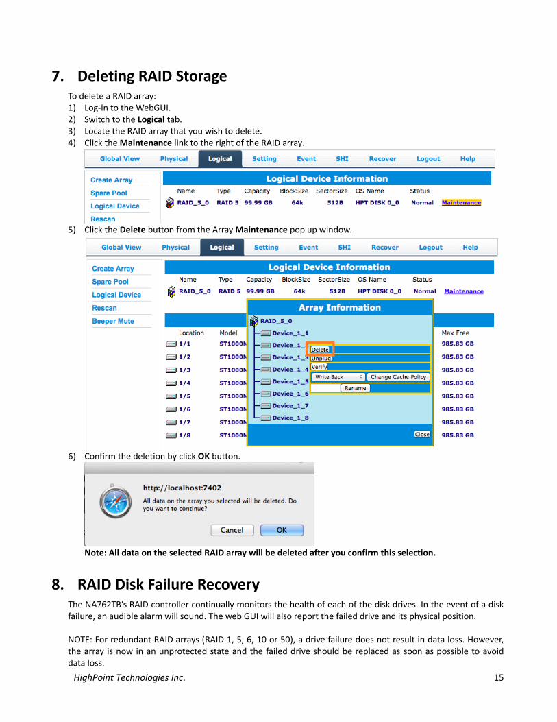
7. Deleting RAID Storage To delete a RAID array: 1) Log-in to the WebGUI. 2) Switch to the Logical tab. 3) Locate the RAID array that you wish to delete. 4) Click the Maintenance link to the right of the RAID array.
5) Click the Delete button from the Array Maintenance pop up window.
6) Confirm the deletion by click OK button.
Note: All data on the selected RAID array will be deleted after you confirm this selection.
8. RAID Disk Failure Recovery The NA762TB’s RAID controller continually monitors the health of each of the disk drives. In the event of a disk failure, an audible alarm will sound. The web GUI will also report the failed drive and its physical position. NOTE: For redundant RAID arrays (RAID 1, 5, 6, 10 or 50), a drive failure does not result in data loss. However, the array is now in an unprotected state and the failed drive should be replaced as soon as possible to avoid data loss.

HighPoint Technologies Inc. 16
NOTE: If the NA762TB was configured in RAID 6 mode, up to two drives can fail with no loss of data. Replace any failed drive as soon as possible. Follow the steps below to identify and replace a failed drive. 1) Launch the WebGUI 2) Mute the alarm with the Beeper Mute button. 3) The WebGUI will display information like that shown below. An exclamation mark on the RAID array icon
indicates that the “Status” of the array is Critical. The lower portion of the GUI indicates which drive in which disk unit has failed.
Note: In this example drive 4 of the RAID 5 Array of has failed.
4) Unlock the disk module Key and remove the failed drive by gently sliding the drive module out of the enclosure. WARNING: Make absolutely sure that you remove the failed drive indicated by the GUI. The HDD status LED can also help locate the Failed disk. When the disk has failed, the NA762TB’s HDD status LED will emit a solid red light. Reinstall the disk module immediately if you remove the wrong disk module.
5) Replace the failed drive with a new disk module and secure in place. Once the drive has spun up to speed, the GUI will indicate that the array is rebuilding (The “Status” shows Rebuilding and the percentage complete) as shown below. The rebuild time is approximately 2 hours per TB.
6) Once the rebuild is complete, the RAID array will return to the Normal status. Your data is now secure.

HighPoint Technologies Inc. 17
9. Expanding RAID Storage Capacity Note: Mac OS X cannot support partition expansion – DO NOT attempt to use the WebGUI’s OCE or ORLM functions with a Mac system.
To Expand RAID storage capacity:
a. Back up all original data to a separate storage device. b. Delete the current RAID array c. Create a new array using the original and added disks. d. Restore the data from the backup source to the new array.
10. NA762TB Audible Alarm The NA762TB has two internal Alarm buzzers. These two Alarm buzzers will emit different types of sound when an error condition is detected.
10.1 Storage controller buzzer: This buzzer is for HDD failure (offline) status notification and it will emit a high pitch continuous sound. This alarm will sound when a disk failure occurs or a disk or an array is removed without using the “unplug” feature in the WebGUI. When the sound is triggered, follow the steps below to check the HDD status and mute the alarm.
a. Open the WebGUI and switch to the logical tab. The alarm can be stopped using the WebGUI’s Mute button, or the Rescan function found under the Physical or Logical tabs.
b. Check the physical device status if there are any disabled drives.
c. Locate the disk module number. The NA762TB’s HDD status LED will emit a solid red light if a disk has failed. Check the HDD status LED and locate the failed disk.
d. If the RAID is in critical status, please follow “Chapter 8 RAID Disk Failure Recovery” to recover the RAID disk
e. For other RAID status, please refer p.37 for RAID recovery
10.2 Enclosure buzzer The alarm buzzer will emit an intermittent sound when a cooling fan has failed, or the enclosure is overheating. Follow the steps below to check the enclosure status and mute the alarm.
a. Use the mute button on the front panel of NA762TB to mute the alarm.
b. Check if the FAN and Temperature LED from the front panel of NA762TB is light on red.
c. If the enclosure alarm actives, this is usually related to NA762TB hardware problem. Please contact Technical Support and report the issue.
HighPoint Technologies Inc. 18
11. Technical Support If you encounter any problems while utilizing the HighPoint NA762TB, or have any questions about this or any other HighPoint Technologies, Inc. product, feel free to contact our Customer Support Department.
Web Support: http://www.highpoint-tech.com/websupport/
Thunderbolt™ Support: Phone: (408)240-6108 Skype: HighPoint.Thunderbolt
12. LIMITED WARRANTY HighPoint warrants your Product against any defect in material and workmanship, under normal use, for the designated warranty period. If the Product should become defective within the warranty period, HighPoint will at its discretion, repair or replace the Product. Repair or replacement parts or Products will be furnished on an exchange basis and will be either new or reconditioned. All replaced parts or Products shall become the Property of HighPoint. This warranty shall not apply if the Product has been damaged by accident, misuse, abuse or as a result of unauthorized service or parts. Warranty service is available to the purchaser by obtaining a Return Material Authorization number (RMA) and by delivering the Product during the warranty period to an authorized HighPoint service facility or to HighPoint. The purchaser shall bear all shipping, packing and insurance costs and all other costs, excluding parts and labor, necessary to effectuate repair, replacement or refund under this warranty. All returned products must be shipped to HighPoint in the original shipping container. For more information on how to obtain warranty service, an RMA number or to acquire shipping materials, contact HighPoint Technical Support. The support information is listed on Chapter 11 section.
IN THE EVENT A PRODUCT BECOMES DEFECTIVE DURING THE WARRANTY PERIOD, THE PURCHASER’S EXCLUSIVE REMEDY SHALL BE REPAIR OR REPLACEMENT AS PROVIDED ABOVE. INCIDENTAL OR CONSEPROUENTAL DAMAGES, INCLUDING WITHOUT LIMITATION LOSS OF DATA, ARISING FROM BREACH OF ANY EXPRESS OR IMPLIED WARRANTY ARE NOT THE RESPONSIBILITY OF GTECH AND, TO THE EXTENT PERMITTED BY LAW, ARE HEREBY EXCLUDED BOTH FOR PROPERTY DAMAGE, AND TO THE EXTENT NOT UNCONSCIONABLE, FOR PERSONAL INJURY DAMAGE

HighPoint Technologies Inc. 19
APPENDIX A - Using the WebGUI (full guide) HighPoint’s web-based RAID Management Software (also known as the WebGUI) is used to monitor and configure hard disks and RAID arrays attached to HighPoint RocketRAID host adapter which is intergraded to the NA762TB.
1. Running the HighPoint Web RAID Management software (WebGUI)
After downloading and installing the WebGUI, open the WebGUI by double-clicking the icon found on the desktop:
Login to the WebGUI and configure the RAID arrays. Use the default user name: RAID and password: hpt to login
Remote Login
Users connected to a local network can remotely access the WebGUI through the IP address the machine is located on.
Open a terminal and type in the following command: ifconfig
Once the IP address is obtained users can remotely access the machine by typing in the following address:
http://IP Address:7402
HighPoint Technologies Inc. 20
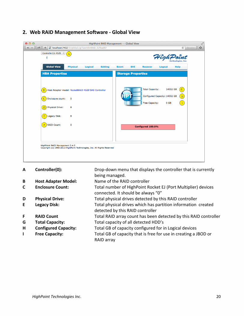
2. Web RAID Management Software - Global View
A Controller(0): Drop-down menu that displays the controller that is currently being managed.
B Host Adapter Model: Name of the RAID controller C Enclosure Count: Total number of HighPoint Rocket EJ (Port Multiplier) devices
connected. It should be always “0” D Physical Drive: Total physical drives detected by this RAID controller E Legacy Disk: Total physical drives which has partition information created
detected by this RAID controller F RAID Count Total RAID array count has been detected by this RAID controller G Total Capacity: Total capacity of all detected HDD’s H Configured Capacity: Total GB of capacity configured for in Logical devices I Free Capacity: Total GB of capacity that is free for use in creating a JBOD or
RAID array

HighPoint Technologies Inc. 21
3. Web RAID Management Software - Physical
3.1 Physical - Controller
A. Controller Information
It lists the following controller information Model Name: RAID controller model number BIOS Version: RAID controller BIOS version Vendor: Vendor Name PCI Bus Number: PCI slot information PCI Device Number: PCI device number PCI Func Number: PCI function number
B. Extended Information It lists controller other information such as processor type, temperatures, voltage, SDRAM, Battery, Firmware version, and SAS address.
C. Update Firmware Controller BIOS/Firmware can be update from Physical page. Browse for BIOS image and click the Submit button.

HighPoint Technologies Inc. 22
3.2 Physical - Devices
A. Physical Device Information: Itlists devices attached to this controller. Information includes disk model name and capacity.
B. By clicking device icon, it displays detail device properties Unplug:
Powers off the device or RAID array and allow you to remove the device
Model: Device model information Revision: Firmware revision Location: Location number of the device on the RAID controller Max Free: Max free space for creating a single disk JBOD or to be part of a
RAID array Status: Device status is Legacy or Normal Serial Number:
Serial Number of device
Capacity: Total capacity of the device Read Ahead: Caching mode to improve Read performance Write Cache: Caching mode to improve Write performance NCQ: Native Command Queuing, I/O commands that are in a queue are
re-ordered for better efficiency

HighPoint Technologies Inc. 23
Identify LED: A blinking cursor to identify the location of a HDD
3.3 Physical - Rescan
The item will rescan the controller to detect devices.
4 Web RAID Management Software - Logical
A. Logical Device Information: It is the logical disk that is connected to the RAID controller and has already been reported to the operating system. Example: Mac OSX – “Disk Utility”
B. Physical Device Information: The physical disk attached to the RAID controller.
4.1 Logical - Create Array To create an array, users need to provide information to tell utility how to construct this array. This section gives a detail description. The following diagram shows the creation page.

HighPoint Technologies Inc. 24
A. Array Type
Choose the RAID type to create. The NA762TB’s RAID controller supports RAID 0, 1, 5, 6, 10, 50 & JBOD.

HighPoint Technologies Inc. 25
B. Array Name Enter the name for the RAID array.
C. Initialization Method The initialization of array is to clean up array disk so there is no invalid data exists. This is essential for array with parity information. During data rebuilding, only valid parity data can re-construct the correct data. There are four options to choose from.
1. Keep Old Data: This is the default option when creating a RAID array. a. This option leaves existing data intact. b. This option does not initialize the array disk. You can use this option when creating RAID
arrays with new hard disks (initialization is not generally necessary for new drives, as they contain no data).
c. In some cases, this option can be used to recover disabled RAID arrays.
2. Quick Init: The RAID array will be immediately accessible. a. This option will delete all content on the disks. b. This option will not perform disk array initialization. When new HDD’s are used this option
can be ignored since there is no data on the hard disk.
3. Foreground: The RAID array is not accessible until initialization is completed. a. This option will delete all content on the disks. b. The logical disks will not be reported to the operating system until initialization is complete.
This method is faster than “Background”, and requires far less time to complete.
4. Background: The RAID array is accessible while disk initialization is being performed. a. This option will delete all content on the disks. b. This method will slow the initialization process, but allows the array to be utilized
immediately
HighPoint Technologies Inc. 26
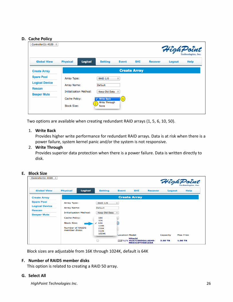
D. Cache Policy
Two options are available when creating redundant RAID arrays (1, 5, 6, 10, 50).
1. Write Back Provides higher write performance for redundant RAID arrays. Data is at risk when there is a power failure, system kernel panic and/or the system is not responsive.
2. Write Through Provides superior data protection when there is a power failure. Data is written directly to disk.
E. Block Size
Block sizes are adjustable from 16K through 1024K, default is 64K
F. Number of RAID5 member disks This option is related to creating a RAID 50 array.
G. Select All

HighPoint Technologies Inc. 27
User can select how many disks to construct the array or click this “select all” to use all HDDs for the array creation.
H. Capacity This allows users to define how much disk capacity will be used. If “maximum” is chosen, then it means use all calculated available disk space.
After the array has been created, it will be displayed under “Logical Device Information” (4.3).
The following information is displayed for each logical device:
Name: Default name of the RAID array Type: Type of RAID array Capacity: Total capacity of the RAID array Cache Policy: Redundant RAID array options for performance or protection Block Size: RAID array block size Sector Size: RAID array sector size OS Name: Name of HDD seen in the OS Status: Status of RAID array. Other option include (Normal, Critical,
Disable, Rebuilding, Verifying)
Array Maintenance: Maintenance provides a selection of general maintenance features and options for the selected array:
1. Diagram 1: Array is in “Normal” Status

HighPoint Technologies Inc. 28
2. Diagram 2: Array is in “Critical” status
The arrays current status and RAID level determine which options and features are provided by Maintenance:
1. Delete : Delete the selected RAID array 2. Unplug : Power off the RAID array and remove it. Without using this feature, removing any disk
member will trigger the alarm. 3. Verify : This option is only available when RAID is in “Normal” status. 4. Add : This option is only available when RAID is in “Critical” status. Click the “add disk”
button to add a new disk in. The following diagram shows how to add a free disk to join the critical array rebuilding.
HighPoint Technologies Inc. 29
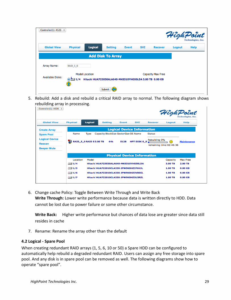
5. Rebuild: Add a disk and rebuild a critical RAID array to normal. The following diagram shows
rebuilding array in processing.
6. Change cache Policy: Toggle Between Write Through and Write Back Write Through: Lower write performance because data is written directly to HDD. Data
cannot be lost due to power failure or some other circumstance.
Write Back: Higher write performance but chances of data lose are greater since data still
resides in cache
7. Rename: Rename the array other than the default
4.2 Logical - Spare Pool
When creating redundant RAID arrays (1, 5, 6, 10 or 50) a Spare HDD can be configured to automatically help rebuild a degraded redundant RAID. Users can assign any free storage into spare pool. And any disk is in spare pool can be removed as well. The following diagrams show how to operate “spare pool”.

HighPoint Technologies Inc. 30
4.3 Logical – Logical Device
Displays logical devices hosted by the NA762TB.

HighPoint Technologies Inc. 31
4.4 Logical - Rescan
When hot-plugging a single device or RAID array, the Rescan button prompts the RAID controller to scan for device changes.
4.5 Logical - Beeper Mute
This will temporarily disable the internal speaker on the RAID controller.
5 Web RAID Management Software - Setting
This tab displays various controller settings and options:
5.1 Setting - System
A. Enable auto rebuild: If enabled, any new disk attached to the RAID controller will be used to rebuild the critical RAID array. Note: The new disk needs to be equal to or larger than the minimum capacity among the remaining disk members of the array.
B. Enable Continue Rebuilding on error:
Enabled by default. If disabled, the WebGUI will ignore bad sectors/read failures and allow the rebuild process to continue. Warning: this option should only be enabled in the case of an emergency – data inconsistency or data loss may result. Review the Event Log before enabling this option, and check for HDD bad

HighPoint Technologies Inc. 32
sector events. If bad sectors are found, we recommend first contacting the HDD manufacturer, then technical support, for further advice.
C. Enable audible alarm:
When a disk goes off-line the beeper on the RAID controller will sound.
D. Set Spindown Idle Disk (Minutes):
Hard drives can be instructed to spin down when there is no disk activity for a set period of time. You are free to specify the interval – from 10 to 240 minutes.
E. Restrict to localhost access:
This option is used to restrict WebGUI access to the local system and not allowing remote access.
F. Set Rebuild Priority: When rebuilding a critical RAID array, there are five rebuilding options to choose from. Each rebuild priority will affect the rebuild completion time.
Lowest Lowest Priority when rebuilding arrays. System resources will be assigned to all other tasks first.
Low Low Priority. Most of the system’s tasks have priority over the rebuild procedure.
Medium Medium Priority is the default option – system resources are equally distributed between the rebuild procedure and other system tasks.
High High Priority – the majority of available system resources will be directed towards the rebuild procedure.
HighPoint Technologies Inc. 33
Highest Highest Priority – the RAID controller will utilize all available system resources to rebuild the array.
G. Port Number 7402: The listening port number used to log into the WebGUI. 7402 is
the default port number. Other port numbers can be used in place of the default as long as they are free.
H. Password Setting: The default password “hpt” can be changed. Note: If the current password is lost or forgotten, you can uninstall and reinstall the Web RAID Management software to restore the default settings. When changing the password, the maximum number of characters allowed is eight.
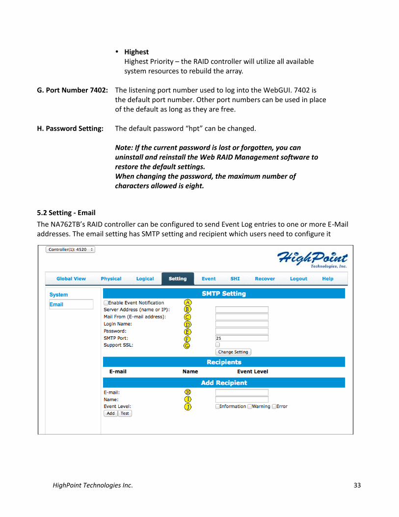
5.2 Setting - Email
The NA762TB’s RAID controller can be configured to send Event Log entries to one or more E-Mail addresses. The email setting has SMTP setting and recipient which users need to configure it

HighPoint Technologies Inc. 34
A. Enable Event Notification:
Check this item to enable Event Notification
B. Server address: This is SMTP mail server address. It can be IP address or SMTP name
C. Mail From: This is email address of the sender D. Login Name: The login name of send’s email account E. Password: The login password of send’s email account F. SMTP Port: This is SMTP port number. The default is 25 for non-SSL
SMTP server G. Support SSL: Check this box if using SSL SMTP and change SMTP port to
SSL port number. Click “Change setting” to save new information.
H. Support SSL: Setup the recipient’s email address I. Name: The name of the recipient J. Event level Check which information that you want to send out for
monitoring. The “Test” check-box is used to verify if email setting is working.
6 Web RAID Management Software - Event
The Event tab will open the Event View interface. Event View logs all RAID related activity including administrative actions, warnings and hardware failures.

HighPoint Technologies Inc. 35
There are three options to operate this event log section
Clear: Click “Clear” to remove all current entries from the Event View log.
Next: The Event View log can span several pages. Click “Next” to view past entries.
Download: The Event View log can be saved as a text file for reference.
7 Web RAID Management Software - SHI (Storage Health Inspector)
Storage Health Inspector:
SHI will inspect each HDD periodically. If any abnormal status is found, it will be recorded in the Event log. SHI can help to identify problems with HDD’s and prevent further damage or data loss. If additional proof of errors is needed, the HDD’s can be placed onto the onboard SATA/SAS port and a 3rd party SMART software utility can be run.
HDD Temperature Threshold:
Setup the HDD temperature threshold to prevent HDD overheating. When the HDD goes beyond the threshold an alert will be triggered.
SMART: SMART attributes for each HDD will be displayed. The following diagram display detail SMART information read out from HDD
Schedule This allows user to schedule a task to run

HighPoint Technologies Inc. 36
When “schedule” button is checked, it displays the following configuration page to schedule a task to run.
Task List: The Task tab allows you to schedule maintenance sessions for RAID 1, 5, 6, 10 and 50 arrays. User can name each task and specify the frequency, date, hour, minute and second for each session. Regular maintenance is highly recommended for any redundant RAID array, and is essential for maintaining healthy, reliable storage configurations.

HighPoint Technologies Inc. 37
8 Web RAID Management Software - Recover
Recover can help repair RAID arrays that have been assigned the disabled status. This feature helps protect RAID configurations by storing multiple copies of RAID configuration data, which administrators can use to restore a disabled RAID array.
Note: Please refer the How-To guide that explains this Recover feature: http://www.highpoint-tech.com/PDF/support/WebGUI_Recover_Feature.pdf

HighPoint Technologies Inc. 38
APPENDIX B - Web RAID Management ICON Definition List The following table lists the definition of each ICON used by the RAID Management interface (The examples use a RAID 5 array for reference).
Icon Description
The array status is "Normal".
The array has stopped “Initializing”. Current status is “Uninitialized”.
The array is “Initializing”: Initializing (Foreground) and Initializing (Background).
The array is performing a data consistency checking and its current status is “Verifying”.
The array status is "Critical" - a disk is missing from the RAID array.
The array status is "Verifying". This indicates that the array is running a data integrity check.
The array status is "Rebuilding". This occurs when the data verification fails or when adding a new disk into the "Critical" array.
The array status is "Critical". This indicates that current array needs "rebuild". This icon will also show up on a device in a RAID disk member as needing to "rebuild" its data.
The status of the "Array" or "Device" is "Disabled".
The array is "Initializing". There are two types of initialization- Foreground and Background.
The array OCE/ORLM operation has stopped.
This icon means the RAID array is "Uninitialized". On the RAID array either Foreground or Background initialization has stopped (Incomplete).
On a disk ( ), it indicates that the disk is not initialized and will need to be initialized for the 1st time before it can be used with HighPoint RAID card.
The device status "Legacy". An existing file system has been created

HighPoint Technologies Inc. 39
on the HDD.
The device is a "Spare". It is used to replace the failed RAID disk member to rebuild automatically.
Information.
Warning.
Error.
The array is inconsistent and it needs to “rebuild”. The current status is “Critical”.
Array disk member diagram is listed below.
It shows a RAID-5 disk member is lost and its current status is “Critical”. Array disk member diagram is listed below.
The array is “rebuilding” and its current status is “Rebuilding”. Array disk member diagram is listed below.
The array is not available. Two scenarios can cause this to happen. First - a lost RAID disk member exceed the minimum required to maintain a RAID level. Second - a disk failed before the initialization or
HighPoint Technologies Inc. 40
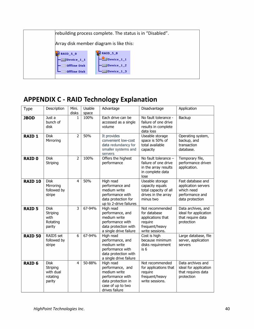
rebuilding process complete. The status is in “Disabled”.
Array disk member diagram is like this:
APPENDIX C - RAID Technology Explanation Type Description Mini.
disks Usable space
Advantage Disadvantage Application
JBOD Just a bunch of disk
1 100% Each drive can be accessed as a single volume
No fault tolerance - failure of one drive results in complete data loss
Backup
RAID 1 Disk Mirroring
2 50% It provides convenient low-cost data redundancy for smaller systems and servers
Useable storage space is 50% of total available capacity
Operating system, backup, and transaction database.
RAID 0 Disk Striping
2 100% Offers the highest performance
No fault tolerance – failure of one drive in the array results in complete data lose
Temporary file, performance driven application.
RAID 10 Disk Mirroring followed by stripe
4 50% High read performance and medium write performance with data protection for up to 2-drive failures
Useable storage capacity equals total capacity of all drives in the array minus two
Fast database and application servers which need performance and data protection
RAID 5 Disk Striping
with Rotating parity
3 67-94% High read performance, and
medium write performance with data protection with a single drive failure
Not recommended for database
applications that require frequent/heavy write sessions.
Data archives, and ideal for application
that require data protection
RAID 50 RAID5 set followed by stripe
6 67-94% High read performance, and medium write performance with data protection with a single drive failure
Cost is high because minimum disks requirement is 6
Large database, file server, application servers
RAID 6 Disk Striping with dual
rotating parity
4 50-88% High read performance, and medium write
performance with data protection in case of up to two drives failure
Not recommended for applications that require
frequent/heavy write sessions.
Data archives and ideal for application that requires data
protection

HighPoint Technologies Inc. 41
APPENDIX D - Thunderbolt Daisy Chain configuration Thunderbolt’s Daisy Chain feature can connect the host system with 6 Thunderbolt devices (or 5 devices and 1 display).
Configuration 1: Connect the host with 6 Thunderbolt Devices.
Configuration 2: Connect the host with 5 Thunderbolt devices and one display.