na series quarter turn actuator - acrodyne · 1 na series quarter turn actuator instruction and...
TRANSCRIPT
1
NA SERIES
QUARTER TURN ACTUATOR
Instruction and Maintenance Manual
Eunha Machinery Industrial Co., Ltd Kwangmyoung industrial complex 141, 201 Haan-Dong, Kyounggi-Do, Korea
Tel : 02) 806-4263 Fax : 02) 806-4266

1
General
1. General
2. Pre-caution before installation
3. Storage
4. Mounting base
5. Drive Bushing
6. Cable connection
7. Internal Wiring
8. Set Limit Switches
9. Set Torque Switches
10. Indicatiion
11. Commissioning
12. Trouble Shooting
13. Repair and maintenance
2
General
CAUTION
Before Handling the actuator,
please read instruction manual
and be well aware how to to do.
NA Series actuator is a engineered products which has been designed for
usage of automation of 90o rotary valve or same operating principle
equipment. Internal provisions like as self-locking which prevent reverse
action from valve, Manual Override, and mechanical torque
switches(except for NA06 & 09) which protect actuator from overload,
Space heater for anti-condensation provide optimum condition for actuator
operation.
Enclosure
Al alloy enclosure is treated by Hard-anodized and powder coated.
Therefore it can be used under severe corrosive atmosphere.
All enclosures are designed to provide IP67grade ingress protection with
explosion proof structure and to provide best performance under any
circumstances.
Performance and applicable range
13 model of NA06, 09, 15, 19, 28, 38, 50, 60, 80, 100, 150, 200, 250
provide various torque 6Kg.m~ 250Kg.m and these are suitable for
operation of 50A ~600A of butterfly valve, 40A~400A of Ball valve, and
other 90o rotary equipment like as Damper.
3
General
Lubrication and convenient installation for any direction
NA Series actuator has double worm gearing, and the mechanism is fully
filled with grease.
There is no leak of lubricant because housing is totally enclosed structure.
Therefore installation for any direction is possible on the purpose.
Inspection, Measurement and test
The performance and quality of NA Series actuators are certified by
factory through out the leak, torque test and other necessary
measurement after assembly and 100% certified product only delivered to
customer.
Temperature, Humidity and Altitude
NA Series Actuators are designed suitable for following condition.
User should note these conditions when you select actuator.
Ambient Temperature : -10oC ~ 55
oC
Max. Temp. of fluid : 80oC
Relative Humidity : RH90%
Altitude : Lower than 1000m
1
Commissioning
1. Please check if the supplied actuator is suitable one for your
application.
2. Please check Model, Mounting base, Electrical specification and
options comparing to your specification for puschasing.
(Can check these on the name plate mounted on actuator)
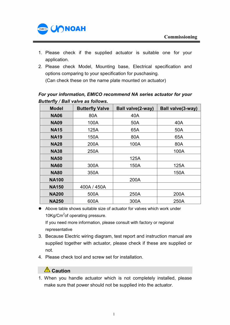
For your information, EMICO recommend NA series actuator for your
Butterfly / Ball valve as follows.
Model Butterfly Valve Ball valve(2-way) Ball valve(3-way)
NA06 80A 40A
NA09 100A 50A 40A
NA15 125A 65A 50A
NA19 150A 80A 65A
NA28 200A 100A 80A
NA38 250A 100A
NA50 125A
NA60 300A 150A 125A
NA80 350A 150A
NA100 200A
NA150 400A / 450A
NA200 500A 250A 200A
NA250 600A 300A 250A
� Above table shows suitable size of actuator for valves which work under
10Kg/Cm2of operating pressure.
If you need more information, please consult with factory or regional
representative
3. Because Electric wiring diagram, test report and instruction manual are
supplied together with actuator, please check if these are supplied or
not.
4. Please check tool and screw set for installation.
Caution
1. When you handle actuator which is not completely installed, please
make sure that power should not be supplied into the actuator.
2
Commissioning
2. If limit switches are not set yet, please make sure that actuator should
not be fully open or close.
Actuator should be stored at dry and clean place if it is not immediately
installed after delivery.
The place should
There should be no severe vibration and temperature change in the place.
If it is high humidity, power should be supplied at least every two week in
order to operate the heater to prevent condensation.
Also, please do not remove the plug which mounted into actuator cable
entry until wiring is ready in the field.
CAUTION
: If trouble due to inappropriate storage
and place, EMICO can not guaranty the
performance and quality.
3
Commissioning
Please be careful not to operate actuator to fully close or fully open until
the direction of actuator is not confirmed (Especially 3 phase electricity).
Also if limit switches are not completely set yet, it can be a major cause of
damage of valve and actuator.
(Limit switches are already set when delivery, limit switches can be set
again in the field if necessary).
It is very simple to operate actuator by manual or electrical as follows.
Manual operation
If you want to operate actuator by manual, pull the lever (toward
handwheel), so that clutch is to be engaged with handwheel.
If it is engaged, then you can operate actuator to any direction by manual.
Direction Indication of Open and Close is marked on the handwheel and
handle cover and in general, to turn clockwise is close and counter
clockwise is open.
Electrical operation
After completion of wiring, you can operate actuator by switch in the
Local panel.
If electricity is supplied, actuator automatically returns from manual to
electrical operation mod.
If lever lean toward opposite side of handwheel, you can acknowledge it
as electrical operating mode.
1
Indication
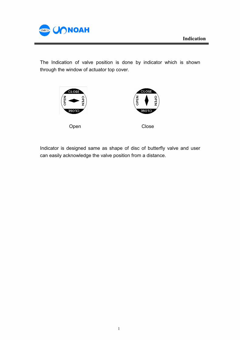
The Indication of valve position is done by indicator which is shown
through the window of actuator top cover.
Open Close
Indicator is designed same as shape of disc of butterfly valve and user
can easily acknowledge the valve position from a distance.
1
Electrical wiring
Taking off Top cover
By using the L-wrench, unscrew the screw of top cover and take off the
top cover from assembly.
Electrical wiring
Wiring should be done as per the wiring diagram which is provided
together with actuator. Especially electricity (voltage, phase and hertz)
should be confirmed comparing to the details on nameplate.
Warning
Relays for power supply should not be
connected to more than two actuators.
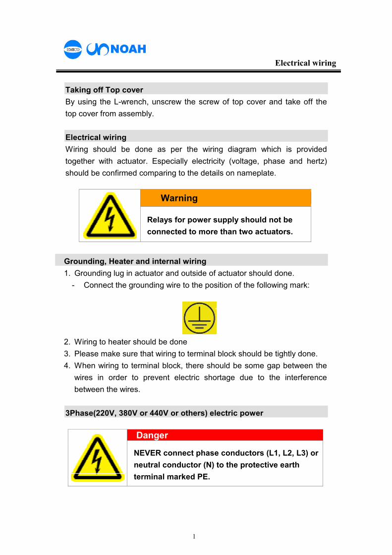
Grounding, Heater and internal wiring
1. Grounding lug in actuator and outside of actuator should done.
- Connect the grounding wire to the position of the following mark:
2. Wiring to heater should be done
3. Please make sure that wiring to terminal block should be tightly done.
4. When wiring to terminal block, there should be some gap between the
wires in order to prevent electric shortage due to the interference
between the wires.
3Phase(220V, 380V or 440V or others) electric power
Danger
NEVER connect phase conductors (L1, L2, L3) or
neutral conductor (N) to the protective earth
terminal marked PE.
2
Electrical wiring
Because there is no way to identify each phase among 3 phase, user
should confirm the actuator correct rotating direction.
Otherwise, it can be a major problem of motor burning.
In order to check correct rotating direction for start up, followings should
be done.
1. Make valve disc 45o position by using manual handwheel of actuator.
2. Push the Close or Open switch for approx. 3seconds, check the
rotating direction of valve disc.
3. If direction of valve disc is reverse, immediately stop the actuator and
check the wiring again.
Then change 2 wires each other among 3 wires(U V W).
Single phase(110V or 220V) Power
When wiring, please be careful not to supply power to open and close
terminal simultaneously.
This is a major cause of motor burning and after service at free of charge
is impossible.
Others after wiring
After completion of wiring, make internal wires well arranged by using
cable tie & etc and remove substance in the actuator if any in order to
avoid any trouble due to the substance.
After completion of all wiring and arrangement in internal, put the top
cover on the housing and fasten the 4 retaining screws.
Caution :
Without confirmation rotating direction of 3 phase, actuator ca be
operated in reverse direction.
In this case, limit switches can not function and therefore Jamming of
gearing or motor burning can occur.
This is not a trouble which free after service is applicable.
1
Cable entry
Cable entry is consist of 2 ea PF 3/4 TAP and when you do wiring through
cable entry, please be careful for following cases.
Cable Gland
Certified products as per standard should be used and there must be tight
sealing by using elastic rubber packing, hardening resin, compound and
metallic packing (metallic seize cable) to prevent any harmful influence
from outside like as moisture or leak of water.
Cable conduit
When use cable conduit, need to make hole for retaining screws on
following parts and tight up with the retaining screws.
Otherwise, it should be tightly fixed through the hole which has no internal
threads.
1. Outside wall of actuator
2. Plate mounted on inside or outside wall of actuator
3. Component for sealing which is a part of wall of actuator or mounted
on wall of actuator.
Others
1. Please make sure that internal wiring to terminal block should be tight
2. Please make Sealed cable entry by factory as it is if you don’t use.
3. Direction of Cable entry toward ground is recommended if possible.
4. Conduit should be a product certified by anti-water leaks, and in case
of usage of uncertified product, after service at free of charge is not
possible.
Ex-proof products
Cable Gland for pertaining performance of ex-proof is not our scope of
supply and certified products by the regulation or standard by local institute
should be used.
If it is difficult, please consult with our regional agent or distributor.
In case of usage of uncertified component and failure, we are free
from the responsibility for that fault.
1
Set of limit switches
Set of Close limit switch
Pulling the lever and turn the handwheel toward clockwise to make valve
full close position.
Then adjusting lower cam to be contacted to close limit switch, tighten the
bolt for limit cam and fix.
Set of Open limit switch
Turning the manual handwheel to counter clockwise and make actuator
full Open.
Then adjust upper cam of limit switch (Open limit switch) as same way to
adjust Close limit switch.
Mechanical Stop Bolt
When you adjust Open & Close limit switch, because Mechanical Stop
Bolt can interrupt the setting of valve operation, turning the mechanical
stop bolt counter clockwise with using L-wrench by 2 turn from open &
close position and tighten it.
Commissioning
After checking of adjustment of Open & Close limit switches and
interruption of Mechanical Stop Bolt, operating actuator 2~ 3 times (Open-
Close, Close-Open) by using switch in control panel, check if each lamp is
on or not.
1
Set of torque switches
Setting of torque switches
Generally speaking, it is not necessary to adjust the torque switches
because the switches are already set by factory before delivery.
But if you still need to adjust the switches, please consult with us or
regional agent
Wrench bolts fastening Torque switches are marked by red paint.
If the bolts are changed and trouble happens because of this change,
EMICO has no responsibility for that problem.
Operating test of torque switches
IN order to check the operating of torque switches, push the roll of micoro
switch of torque switch during open or close operation.
If actuator stop, it means that torque switches work successfully.
Caution :
Torque switches are installed for the purpose of protection of
actuator and valve and because these are set by factory with
precision equipment, EMICO can not guaranty the performance
if these are changed or adjusted without consultation with
factory.
1
Mounting and installation
Drive bushing
Drive bushing for mounting actuator on is supplied for every actuator and
valve stem with key way type is recommended to use.
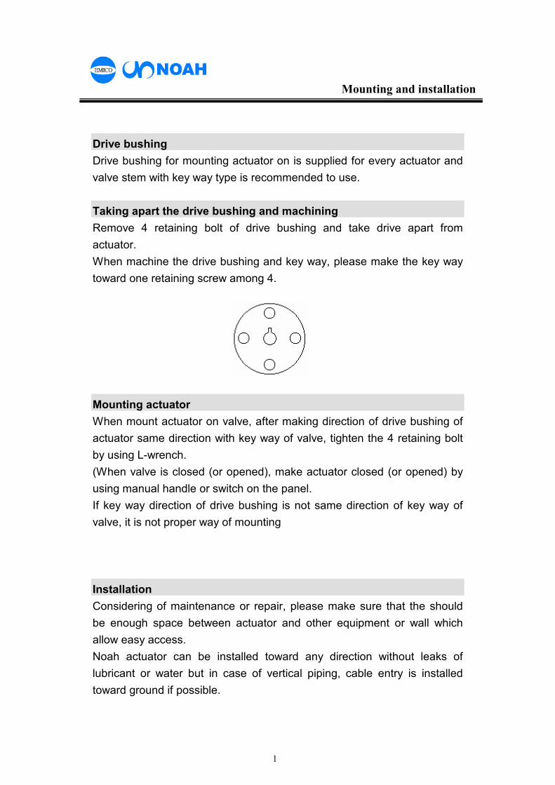
Taking apart the drive bushing and machining
Remove 4 retaining bolt of drive bushing and take drive apart from
actuator.
When machine the drive bushing and key way, please make the key way
toward one retaining screw among 4.
Mounting actuator
When mount actuator on valve, after making direction of drive bushing of
actuator same direction with key way of valve, tighten the 4 retaining bolt
by using L-wrench.
(When valve is closed (or opened), make actuator closed (or opened) by
using manual handle or switch on the panel.
If key way direction of drive bushing is not same direction of key way of
valve, it is not proper way of mounting
Installation
Considering of maintenance or repair, please make sure that the should
be enough space between actuator and other equipment or wall which
allow easy access.
Noah actuator can be installed toward any direction without leaks of
lubricant or water but in case of vertical piping, cable entry is installed
toward ground if possible.
2
Mounting and installation
Also, following cases are to be considered.
In case of butterfly valve
Please be careful when install actuator on butterfly valve because normal
operation is not possible if both face of valve seat are suppressed too
much.
In case of 3way ball valve
Please check if the valve is L port or T port
In case of damper
Please make sure that mounting should be done when damper is
completely closed.
Prior to this, check if rotating direction of damper is same with that of
actuator.
In case of direct mounting and use of rod box, check if damper is open or
close.
It is recommended to use the rod box type for the severe application like
as vibration or high temperature.
1
Mounting base
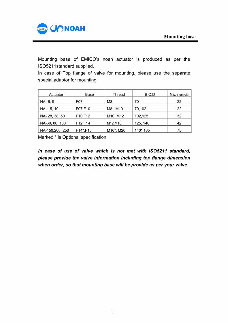
Mounting base of EMICO’s noah actuator is produced as per the
ISO5211standard supplied.
In case of Top flange of valve for mounting, please use the separate
special adaptor for mounting.
Actuator Base Thread B.C.D Max Stem dia
NA- 6, 9 F07 M8 70 22
NA- 15, 19 F07,F10 M8 , M10 70,102 22
NA- 28, 38, 50 F10,F12 M10, M12 102,125 32
NA-60, 80, 100 F12,F14 M12,M16 125, 140 42
NA-150,200, 250 F14*,F16 M16*, M20 140*,165 75
Marked * is Optional specification
In case of use of valve which is not met with ISO5211 standard,
please provide the valve information including top flange dimension
when order, so that mounting base will be provide as per your valve.
1
Trouble Shooting
When operation, there is some cases that operating is not succesful
due to several reason.
I those, please check as per follows
Mechanical trouble
1. Pulling the Hand/Auto lever of actuator, operate the valve by manual
2. If handwheel is O.K, there is no trouble in mechanism and check
electrical trouble.
3. If handwheel is not move, it could be “Jamming” and check as follows.
Jamming happen during close operation, loose mechanical stop bolt by
2 turns which is opposite side from handwheel and pulling the lever and
turn handwheel left.
If doing this and Jammingis released, check the power wiring.
4. If handwheel is operated without any load, mounting between actuator
and vlave is not proper and need to check it
5. If valve is not fully closed or opened, please check adjustment of limit
switches.
6. Valve operation is smooth and well by using manual handwheel, check
“Electrical problem”
1
Trouble Shooting
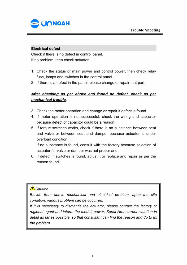
Electrical defect
Check if there is no defect in control panel.
If no problem, then check actuator.
1. Check the status of main power and control power, then check relay
fuse, lamps and switches in the control panel.
2. If there is a defect in the panel, please change or repair that part.
After checking as per above and found no defect, check as per
mechanical trouble.
3. Check the motor operation and change or repair if defect is found.
4. If motor operation is not successful, check the wiring and capacitor
because defect of capacitor could be a reason.
5. If torque switches works, check if there is no substance between seat
and valve or between seat and damper because actuator is under
overload condition.
If no substance is found, consult with the factory because selection of
actuator for valve or damper was not proper and
6. If defect in switches is found, adjust it or replace and repair as per the
reason found.
Caution :
Beside from above mechanical and electrical problem, upon the site
condition, various problem can be occurred.
If it is necessary to dismantle the actuator, please contact the factory or
regional agent and inform the model, power, Serial No., current situation in
detail as far as possible, so that consultant can find the reason and do to fix
the problem.
Maintenance
Noah actuator is designed to withstand for 30 years just same with life of
plant but regular check and maintenance (at least 2 times per year) which
operate actuator
Caution
Please be noticed that free after service is not applicable to
following cases.
1. Damage and trouble caused by user’s inattention
2. Trouble caused by modification or repair without consulting with
EMICO
3. Trouble caused by inappropriate change of our standard wiring
4. Trouble caused by operation without confirmation of rotating
direction( 3phase)
5. Trouble caused inappropriate sealing of cable gland or conduit
6. Trouble caused by force major.
7. Trouble occurred over warranty period
2
Maintenance
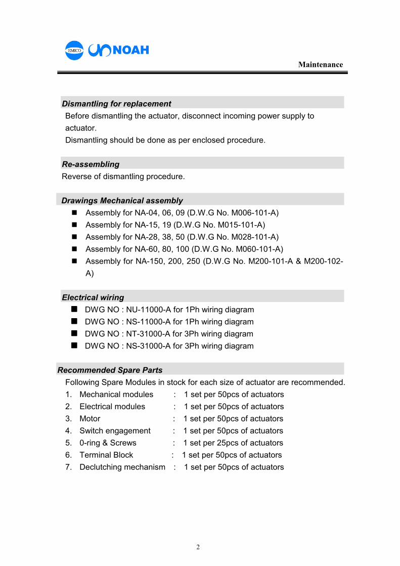
Dismantling for replacement
Before dismantling the actuator, disconnect incoming power supply to
actuator.
Dismantling should be done as per enclosed procedure.
Re-assembling
Reverse of dismantling procedure.
Drawings Mechanical assembly
� Assembly for NA-04, 06, 09 (D.W.G No. M006-101-A)
� Assembly for NA-15, 19 (D.W.G No. M015-101-A)
� Assembly for NA-28, 38, 50 (D.W.G No. M028-101-A)
� Assembly for NA-60, 80, 100 (D.W.G No. M060-101-A)
� Assembly for NA-150, 200, 250 (D.W.G No. M200-101-A & M200-102-
A)
Electrical wiring
���� DWG NO : NU-11000-A for 1Ph wiring diagram
���� DWG NO : NS-11000-A for 1Ph wiring diagram
���� DWG NO : NT-31000-A for 3Ph wiring diagram
���� DWG NO : NS-31000-A for 3Ph wiring diagram
Recommended Spare Parts
Following Spare Modules in stock for each size of actuator are recommended.
1. Mechanical modules : 1 set per 50pcs of actuators
2. Electrical modules : 1 set per 50pcs of actuators
3. Motor : 1 set per 50pcs of actuators
4. Switch engagement : 1 set per 50pcs of actuators
5. 0-ring & Screws : 1 set per 25pcs of actuators
6. Terminal Block : 1 set per 50pcs of actuators
7. Declutching mechanism : 1 set per 50pcs of actuators
3
Maintenance
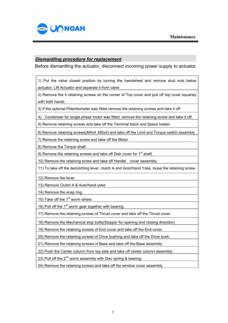
Dismantling procedure for replacement
Before dismantling the actuator, disconnect incoming power supply to actuator.
.
1) Put the valve closed position by turning the handwheel and remove stud nuts below
actuator. Lift Actuator and separate it from valve
2) Remove the 4 retaining screws on the corner of Top cover and pull off top cover squarely
with both hands
3) If the optional Potentiometer was fitted remove the retaining screws and take it off
4) Condenser for single phase motor was fitted, remove the retaining screw and take it off.
5) Remove retaining screws and take off the Terminal block and Space heater.
6) Remove retaining screws(M4x4, M5x4) and take off the Limit and Torque switch assembly
7) Remove the retaining screw and take off the Motor.
8) Remove the Torque shaft
9) Remove the retaining screws and take off Disk cover for 1st shaft.
10) Remove the retaining screw and take off Handle cover assembly.
11) To take off the declutching lever, clutch A and Auto/Hand Yoke, loose the retaining screw.
12) Remove the lever.
13) Remove Clutch A & Auto/hand yoke
14) Remove the snap ring.
15) Take off the 1st worm wheel.
16) Pull off the 1st worm gear together with bearing.
17) Remove the retaining screws of Thrust cover and take off the Thrust cover.
18) Remove the Mechanical stop bolts(Stopper for opening and closing direction)
19) Remove the retaining screws of End cover and take off the End cover.
20) Remove the retaining screws of Drive bushing and take off the Drive bush.
21) Remove the retaining screws of Base and take off the Base assembly
22) Push the Center column from top side and take off center column assembly.
23) Pull off the 2nd worm assembly with Disc spring & bearing.
24) Remove the retaining screws and take off the window cover assembly