na journal of applied - longdom€¦ · tungsten inert gas welding tungsten inert gas (tig) welding...
TRANSCRIPT
Volume 4 • Issue 1 • 1000151J Appl Mech EngISSN:2168-9873 JAME, an open access journal
Open AccessResearch Article
Choudhary, J Appl Mech Eng 2015, 4:1 DOI: 10.4172/2168-9873.1000151
Keywords: TIG joining; MMCs; Taguchi’s methodology; Design ofexperiments; Optimal parametric settings
IntroductionA “composite” is when two or more different materials are
combined together to create a superior and unique material. This is an extremely broad definition that holds true for all composites, however, more recently the term “composite” describes reinforced plastics. One constituents is called the reinforcing phase and one which it is embedded is called the matrix, the reinforcing phase material may be in the form of particles fibers or flakes the matrix materials are generally continuous phase, Aluminum based metal matrix composites (MMCs) reinforced with ceramic particles (Al2O3, SiCp, Graphite etc.) have developed considerable interests in modern industry due to light weight of aluminum and its expensive as compared with other metals such as Titanium and Magnesium [1].
Types of composites
(i) Matrix material (ii) Reinforcements
On the basis of matrix material composites are classified as follows:
(a) Metal matrix composites (b) Polymer matrix composites
(c) Ceramic composites (d) Carbon composites
On the basis of Reinforcements composites are classified as follows:
(a) Particle-reinforced (b) Whisker-or short fibre-reinforced
(c) Continuous fibre-reinforced (d) Mono filament-reinforced
Classification of metal matrix composites (MMCs): AMMCs can be classified into four types depending on the type of reinforcement [2].
(a) Particle-reinforced AMCs (PAMCs)
(b) Whisker-or short fibre-reinforced AMCs (SFAMCs)
*Corresponding author: Rahul Choudhary, Department of Industrial Design,National institute of Technology Rourkela, India, Tel: 0661-2462003; E-mail:[email protected]
Received December 08, 2014; Accepted January 15, 2015; Published January 25, 2015
Citation: Choudhary R (2015) Multi Response Optimization of Tungsten Inert Gas (TIG) Welding of Al6063/15%Sicp Metal Matrix Composites. J Appl Mech Eng 4: 151. doi:10.4172/2168-9873.1000151
Copyright: © 2015 Choudhary R. This is an open-access article distributed under the terms of the Creative Commons Attribution License, which permits unrestricted use, distribution, and reproduction in any medium, provided the original author and source are credited.
Multi Response Optimization of Tungsten Inert Gas (TIG) Welding of Al6063/15%Sicp Metal Matrix Composites.Rahul Choudhary*Department of Industrial Design, National institute of Technology Rourkela, India
AbstractMaterial scientists and researchers in this area have been fulfilling the demand of the engineering sector since
decades in synthesizing materials to attain the demanded properties to enhance efficiency and cost savings in the manufacturing sector Aluminium metal matrix composites (AMMCs) are becoming more popular as structural materials and joining them is therefore of paramount importance. Joining of advanced materials plays an increasingly important role in modern manufacturing industries. AMMCs have a unique combination of mechanical and physical properties, such as high specific strength, specific modulus of elasticity, low thermal expansion coefficient and good wear resistance; these are being widely used in aerospace engineering, automotive industry, electronic packaging, medical appliances, heat exchanger fins and other related industries. As these new materials become available it is necessary to define and optimize joining techniques, and a thorough understanding of process. The present work first deals with the fabrication of SiCp reinforced AMMCs (Al6063/15%SiCp) with Liquid Processing Technique, i.e. Stir casting method and later to seek for possibilities of successful joining with TIG process, for possible structural applications. The present study deals with an experimental study carried out in order to optimize the process parameters namely Frequency (Hz), Current (A), Shielding gas flow rate (l/m), Percentage time electrode positive (μs). The performance measures evaluated are namely Micro- hardness, (VHN) and Impact strength, (Joule), for Tig welding of Al6063/15%SiCp. The results have been analysed using Taguchis methodology. The optimal values of micro-hardness are A1B3C3D1 (frequency HF Hz, current 105 A, shielding gas flow rate 14 l/m, percentage time electrode positive 60 μs). The optimal values for impact strength are A2B1C1D3 (frequency LF Hz, current 85 A, shielding gas flow rate 10 l/m, percentage time electrode positive 70 μs).
(c) Continuous fibre-reinforced AMCs (CFAMCs)
(d) Mono filament-reinforced AMCs (MFAMCs)
Particle reinforced aluminium matrix composites (PAMCs):These composites generally cover equiaxed ceramic reinforcements with an aspect ratio less than about 5. Ceramic reinforcements are normally oxides or carbides or borides (Al2O3 or SiC or TiB2) and present in volume fraction less than 30% when used for organizational and wear resistance applications.
Short fibre-and whisker-reinforced aluminium matrix composites (SFAMCs): These have reinforcements with an aspect ratio of greater than 5, but are not continuous. Short alumina fibre reinforced aluminium matrix composites is one of the first and most popular AMCs to be developed and used in pistons. These were produced by squeeze infiltration process. Whisker reinforced composites are produced by either by PM processing or by infiltration route.
Continuous fibre-reinforced aluminium matrix composites (CFAMCs): Here, the reinforcements are in the form of continuous fibres (of alumina, SiC or carbon) with a diameter less than 20μm. The
Journal of Applied Mechanical EngineeringJo
urna
l of A
pplied Mechanical Engineering
ISSN: 2168-9873
Citation: Choudhary R (2015) Multi Response Optimization of Tungsten Inert Gas (TIG) Welding of Al6063/15%Sicp Metal Matrix Composites. J Appl Mech Eng 4: 151. doi:10.4172/2168-9873.1000151
Page 2 of 8
Volume 4 • Issue 1 • 1000151J Appl Mech EngISSN:2168-9873, an open access journal
fibres can either be parallel or pre woven, interweaved prior to the production of the composite [3].
Mono filament reinforced aluminium matrix composites (MFAMCs): Monofilaments are large diameter (100 to 150 μm) fibres, usually formed by chemical vapour deposition (CVD) of either SiC or B into a core of carbon fibre or W wire. Bending flexibility of monofilaments is low compared to multi filaments.
Properties
Favourable properties of AMMCs are high strength, high stiffness, high temperature stability, improved wear resistant, corrosion resistant, adjustable coefficient of thermal expansion etc. SiCp reinforced aluminium metal matrix composites (SiCp/Al MMCs) have a unique combination of mechanical and physical properties, such as high specific strength and specific modulus of elasticity, low thermal expansion coefficient and good wear resistance [4].
Processing of metal matrix composites (MMCS)
Manufacturing of MMCs at industrial scale can be classified into two main groups [5-7].
(i) Liquid state processes (ii) Solid state processes
Liquid state processes: Liquid state fabrication of Metal MatrixComposites involves incorporation of dispersed phase into a molten matrix metal, followed by its Solidification. In order to provide high level of mechanical properties of the composite, good interfacial bonding (wetting) between the dispersed phase and the liquid matrix should be obtained.
Liquid state processes are also classified as follows: (a) Stir casting (b) Infiltration (c) Gas pressure infiltration (d) Squeeze infiltrationcasting (e) Pressure die Infiltration
Stir casting method of fabrication of MMCs: Stir Casting is a liquid state method of composite materials fabrication, in which a dispersed phase (ceramic particles, short fibres) is mixed with a molten matrix metal by means of mechanical stirring.
Solid phase processes: Solid state fabrication of Metal MMCs is the process, in which Metal Matrix Composites are formed as a result of bonding matrix metal and dispersed phase due to mutual diffusion occurring between them in solid states at elevated temperature and under pressure.
They are classified as following (a) Diffusion bonding
(b) Sintering
Joining metal matrix composites (MMCS)
There are a number of methods available for joining MMCs, some being more successful than others (Table 1). Relative ratings for processes used for bonding MMCs.
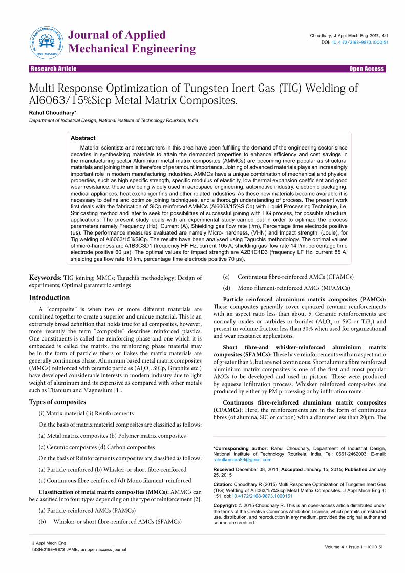
Tungsten inert gas welding
Tungsten Inert Gas (TIG) welding (Figure 1). Also known as Gas Tungsten Arc Welding (GTAW) is a process that produces an electric arc maintained between a non-consumable tungsten electrode and the part to be welded. The heat-affected zone, the molten metal, and the tungsten electrode are all shielded from atmospheric contamination by a blanket of inert gas fed through the TIG torch.
Inert gas (usually Argon) is inactive or deficient in active chemical
properties. The shielding gas serves to blanket the weld and exclude the active properties in the surrounding air. Inert gases, such as Argon and Helium, do not chemically react or combine with other gases. They pose no smell and are transparent, permitting the welder maximum visibility of the arc. In some instances Hydrogen gas may be added to enhance travel speeds [8]. TIG is used to weld steel, stainless steel, nickel alloys, titanium, aluminium, magnesium, copper, brass, bronze, and even gold. TIG can also weld dissimilar metals to one another such as copper to brass and stainless steel to mild steel [9].
Direct current electrode negative (DCEN): Direct current (DC) is an electrical current that flows in one direction only. DCEN is not use due to no cleaning of aluminium oxide layer
Direct current electrode positive (DCEP): When welding with direct current electrode positive (DCEP), the torch is connected to the positive terminal on the welding power source and the ground or work lead is connected to the negative terminal. The electron flow is still from negative to positive; the electrons are now leaving the work
Taguchi orthogonal array
Orthogonal arrays are two dimensional arrays of numbers which possess the interesting quality that by choosing any two columns in the array you receive an even distribution of all the pair –wise combination of values in the array, here is some terminology for working with orthogonal array.
Runs: The number of rows in the array. This directly translates to the number of test cases that will be generated the OATS technique.
Factors: The number of columns in an array. This directly translates to the maximum number of variables that can be handled by this array.
Levels: The maximum number of values that can be taken on by any single factor. An orthogonal array will contain values from 0 to levels 1.
Figure 1: Tungsten Inert gas arc welding process (TIG [7].
Process Sheet Extrusion CastingTIG Good good goodMIG Good good goodResistance Fair n/a n/aLaser Poor poor poorElectron Beam Poor poor poorFriction Welding n/a good goodDiffusion Bonding Fair fair fairFlash Welding n/a good good
Table 1: Relating ratings for processes used for bonding MMCs [6]. Form of MMCs.
Citation: Choudhary R (2015) Multi Response Optimization of Tungsten Inert Gas (TIG) Welding of Al6063/15%Sicp Metal Matrix Composites. J Appl Mech Eng 4: 151. doi:10.4172/2168-9873.1000151
Page 3 of 8
Volume 4 • Issue 1 • 1000151J Appl Mech EngISSN:2168-9873, an open access journal
Taguchi orthogonal array are experimental design that usually require only a fraction of the full factorial combination. The arrays are design to handle as many factors as possible in a certain number of runs. Create Taguchi design by assigning some or all of the array columns to the factors in your experiment. The columns of the arrays are balanced and orthogonal. This means that in each pair of columns, all factor combinations occurs the same number of times. Orthogonal designs allow estimating the effect of each factor on the response or performance measures independently of all other factors.
For our experimentation, we have used L18 orthogonal array. The standard L18 orthogonal array is shown in Table 2, where A is noise factor having two levels and B, C and D being control factors having three levels each.
Here factor A has 2 levels, whereas factor B, C and D have three levels each. Interaction between column 1 and 2 is orthogonal to all columns and hence can be estimated without sacrificing any column [10].
ExperimentationThe objective of the experimentation is to optimization of
tungsten inert gas (TIG) welding process parameter during welding of Al6063/15%SiCp metal matrix composites. A L18 (21 × 33) orthogonal array was employed to study the effect of Frequency, Current, Shielding gas flow rate, Percentage time electrode positive. The performance measures considered were Micro Hardness and Impact Strength The Experimentations were carried out in two steps first is processing of MMCs and then secondly is joining of MMCs by TIG process.
Work material
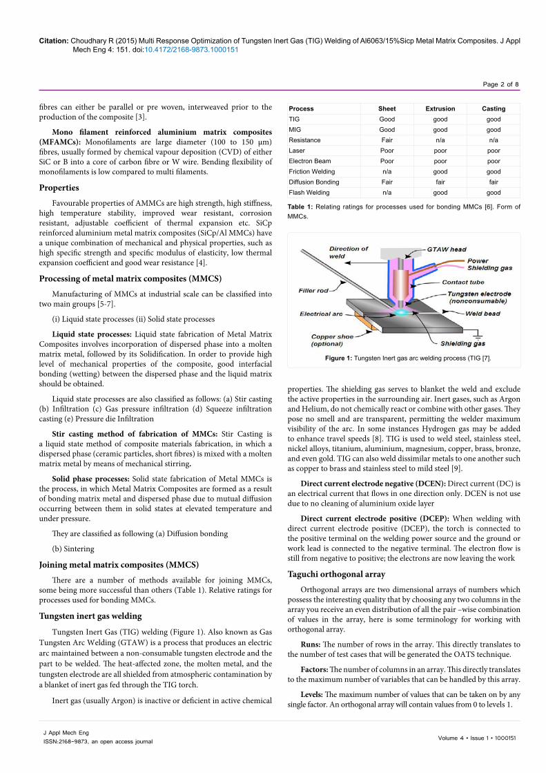
Matrix material: The matrix material used in the investigation is AA6063 (Table 3). Chemical Composition of Aluminium Alloy 6063 (Source: Munjal Casting Pvt. Ltd.) (Figure 2).
Processing of MMCS
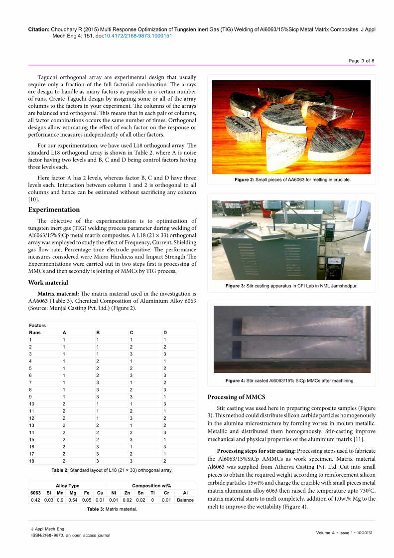
Stir casting was used here in preparing composite samples (Figure 3). This method could distribute silicon carbide particles homogenously in the alumina microstructure by forming vortex in molten metallic. Metallic and distributed them homogenously. Stir-casting improve mechanical and physical properties of the aluminium matrix [11].
Processing steps for stir casting: Processing steps used to fabricate the Al6063/15%SiCp AMMCs as work specimen. Matrix material Al6063 was supplied from Atherva Casting Pvt. Ltd. Cut into small pieces to obtain the required weight according to reinforcement silicon carbide particles 15wt% and charge the crucible with small pieces metal matrix aluminium alloy 6063 then raised the temperature upto 7300C, matrix material starts to melt completely, addition of 1.0wt% Mg to the melt to improve the wettability (Figure 4).
Figure 3: Stir casting apparatus in CFI Lab in NML Jamshedpur.
Figure 4: Stir casted Al6063/15% SiCp MMCs after machining.
FactorsRuns A B C D1 1 1 1 12 1 1 2 23 1 1 3 34 1 2 1 15 1 2 2 26 1 2 3 37 1 3 1 28 1 3 2 39 1 3 3 110 2 1 1 311 2 1 2 112 2 1 3 213 2 2 1 214 2 2 2 315 2 2 3 116 2 3 1 317 2 3 2 118 2 3 3 2
Table 2: Standard layout of L18 (21 × 33) orthogonal array.
Alloy Type Composition wt%6063 Si Mn Mg Fe Cu Ni Zn Sn Ti Cr Al0.42 0.03 0.9 0.54 0.05 0.01 0.01 0.02 0.02 0 0.01 Balance
Table 3: Matrix material.
Figure 2: Small pieces of AA6063 for melting in crucible.
Citation: Choudhary R (2015) Multi Response Optimization of Tungsten Inert Gas (TIG) Welding of Al6063/15%Sicp Metal Matrix Composites. J Appl Mech Eng 4: 151. doi:10.4172/2168-9873.1000151
Page 4 of 8
Volume 4 • Issue 1 • 1000151J Appl Mech EngISSN:2168-9873, an open access journal
Joint design and edge preparation
The joint design used in this work was a single V grove which was selected according to the thickness of the base material, the grove angle is 750 root gap of 2 mm and root face 2 mm was used other relevant information about grove design is shown in Figure 5, the edge preparation was done with the help of shaper M/C.
Pre-cleaning
Before starting welding pre-cleaning the surface of base metal and grove edges is necessary so that dust, oil, rust and other unwanted particles can be removed otherwise these particles may lead to some types of defects in the weld metal.
Factors and levels
(a) Noise factor: Frequency (Hz), no of levels=2
1. Low frequency, (LF) and 2. High frequency, (HF), Degree of freedom (DOF)=1
(b) Control factors: Current (A), no of levels=3, (DOF)=2 Shielding gas flow rate (l/m), no of levels=3, (DOF)=2
Percentage time electrode positive (μs), no of levels=3, (DOF)=2
In the present experimentation study frequency, current, shielding gas flow rate and duration of electrode positive have been considered as process parameters. Thus each process parameters were assigned three levels except frequency based upon the preliminary experiments. The process parameters along with their levels considered for the present study is listened in Table 4.
Taguchi’s orthogonal array: In the present study, L18 (21x33) orthogonal array has been used. Accordingly 18 experiments were carried out to study the effect of process parameters. Each experimental runs were repeated twice in order to reduce experimental errors (Table 5).
Experimental procedure: The joint design used in this work was a single V grove which was selected according to the thickness of the
base material and made by shaper machine, other relevant information about grove design is shown in Figure 5. Pre-cleaning of plate and grove edges was done with the help of wire brush.
Performance measures: The various performance measures or the responses that were studied in the TIG welding of Al6063/15%SiCp metal matrix composite are:
a. Micro-hardness (VHN) hardness is the ability of a metal to resist penetration to resist abrasive wear, or to resist the absorption of energy under impact load; according these can be thought of as penetration hardness, wear hardness, and rebound hardness [12]. Vickers hardness test uses a square based diamond pyramid so it has higher accuracy because the diagonals of a square can be measured more accurately than the diameter of a circle and hardness is present in VHN number [13].
b. Impact strength (Charpy test) the resistance of the material to fracture under impact loading, i.e., under quickly dynamic loads, the quantitative value measured in joules [14].
Factors Unit Levels 1 2 3Frequency Hz HF LF -
(Denoted as 1) (Denoted as 2)
Current A 85 95 105
Shielding gas flow rate l/m 10 12 14
Percentage time electrode positive
Table 4: Process parameters considered and their levels.
Runs Noise factor Control factorFrequency (Hz) Current (A) S.G.F.R (l/m) %Time
electrode + (μs)1 HF 85 10 602 HF 85 12 653 HF 85 14 704 HF 95 10 605 HF 95 12 656 HF 95 14 707 HF 105 10 658 HF 105 12 709 HF 105 14 60
10 LF 85 10 7011 LF 85 12 6012 LF 85 14 6513 LF 95 10 6514 LF 95 12 7015 LF 95 14 6016 LF 105 10 7017 LF 105 12 6018 LF 105 14 65
Table 5: Taguchi’s orthogonal array.
Figure 5: Joining of MMCs work specimen.
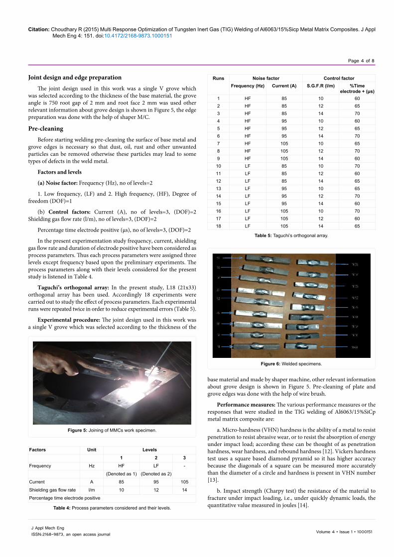
Figure 6: Welded specimens.
Citation: Choudhary R (2015) Multi Response Optimization of Tungsten Inert Gas (TIG) Welding of Al6063/15%Sicp Metal Matrix Composites. J Appl Mech Eng 4: 151. doi:10.4172/2168-9873.1000151
Page 5 of 8
Volume 4 • Issue 1 • 1000151J Appl Mech EngISSN:2168-9873, an open access journal
Testing of work specimens
Testing is considered as the necessary to the satisfactory performance of the welded joints in service for this purpose the specimen dimensions and welding conditions are set and to make the material samples for testing. Following are the different tests that are carried out in the present study (Figures 6 and 7).
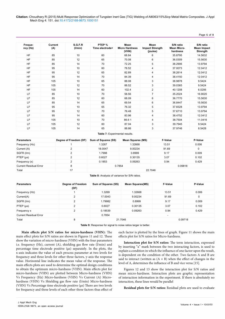
Micro hardness testing (Vickers hardness): For micro-hardness testing the specimens were prepared using standard procedure like belt grinding, polishing using successively fine grades of emery up to 2500 grit size. This is help-full in removing coarse and fine oxide layer as well as scratches on the surface that were to be metal graphically analyzed (Figure 7).
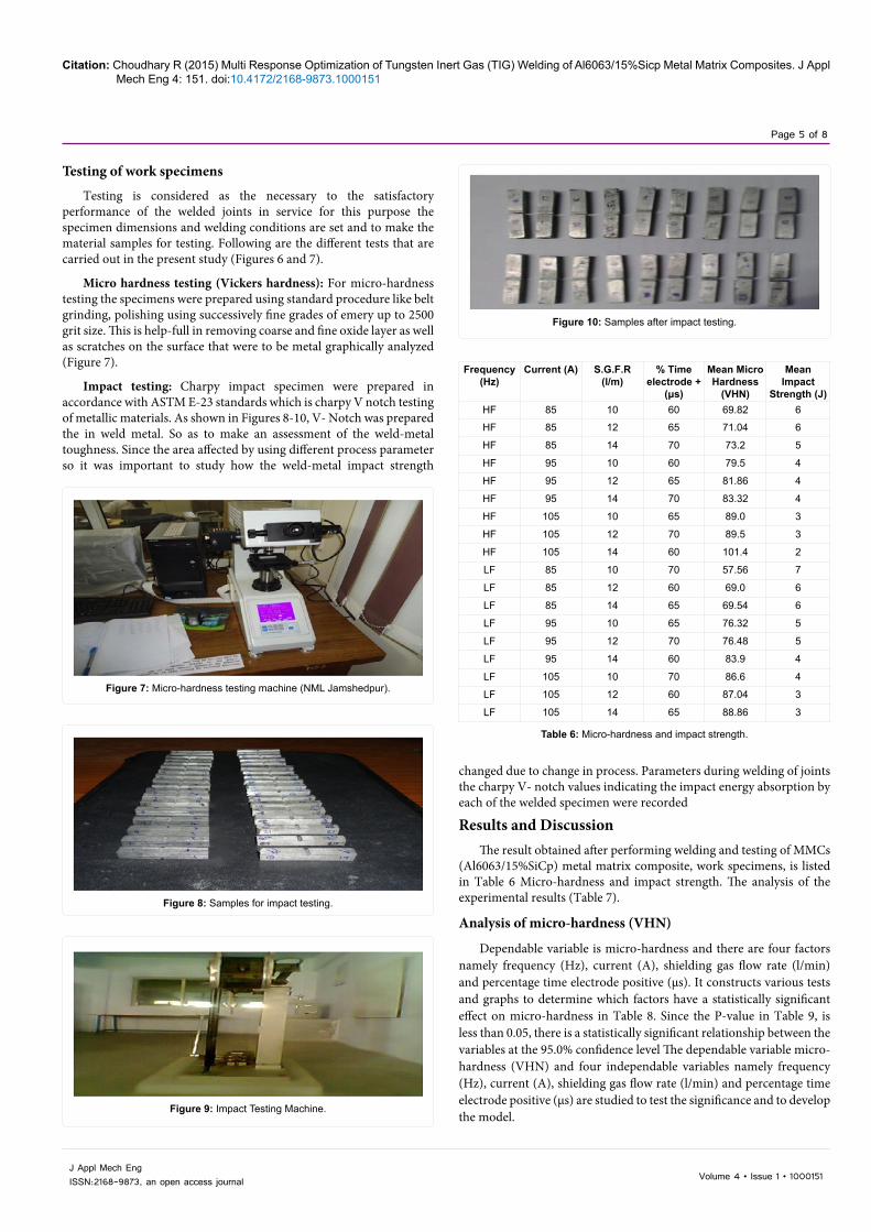
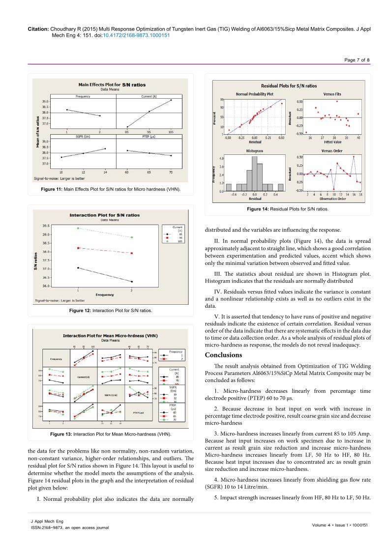
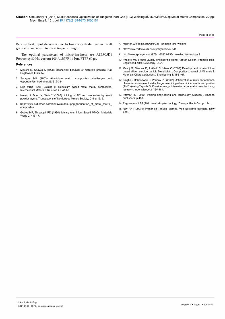
Impact testing: Charpy impact specimen were prepared in accordance with ASTM E-23 standards which is charpy V notch testing of metallic materials. As shown in Figures 8-10, V- Notch was prepared the in weld metal. So as to make an assessment of the weld-metal toughness. Since the area affected by using different process parameter so it was important to study how the weld-metal impact strength
changed due to change in process. Parameters during welding of joints the charpy V- notch values indicating the impact energy absorption by each of the welded specimen were recorded
Results and DiscussionThe result obtained after performing welding and testing of MMCs
(Al6063/15%SiCp) metal matrix composite, work specimens, is listed in Table 6 Micro-hardness and impact strength. The analysis of the experimental results (Table 7).
Analysis of micro-hardness (VHN)
Dependable variable is micro-hardness and there are four factors namely frequency (Hz), current (A), shielding gas flow rate (l/min) and percentage time electrode positive (μs). It constructs various tests and graphs to determine which factors have a statistically significant effect on micro-hardness in Table 8. Since the P-value in Table 9, is less than 0.05, there is a statistically significant relationship between the variables at the 95.0% confidence level The dependable variable micro-hardness (VHN) and four independable variables namely frequency (Hz), current (A), shielding gas flow rate (l/min) and percentage time electrode positive (μs) are studied to test the significance and to develop the model.
Figure 7: Micro-hardness testing machine (NML Jamshedpur).
Figure 8: Samples for impact testing.
Figure 9: Impact Testing Machine.
Frequency (Hz)
Current (A) S.G.F.R (l/m)
% Time electrode +
(μs)
Mean Micro Hardness
(VHN)
Mean Impact
Strength (J)HF 85 10 60 69.82 6
HF 85 12 65 71.04 6
HF 85 14 70 73.2 5
HF 95 10 60 79.5 4
HF 95 12 65 81.86 4
HF 95 14 70 83.32 4
HF 105 10 65 89.0 3
HF 105 12 70 89.5 3
HF 105 14 60 101.4 2
LF 85 10 70 57.56 7
LF 85 12 60 69.0 6
LF 85 14 65 69.54 6
LF 95 10 65 76.32 5
LF 95 12 70 76.48 5
LF 95 14 60 83.9 4
LF 105 10 70 86.6 4
LF 105 12 60 87.04 3
LF 105 14 65 88.86 3
Table 6: Micro-hardness and impact strength.
Figure 10: Samples after impact testing.
Citation: Choudhary R (2015) Multi Response Optimization of Tungsten Inert Gas (TIG) Welding of Al6063/15%Sicp Metal Matrix Composites. J Appl Mech Eng 4: 151. doi:10.4172/2168-9873.1000151
Page 6 of 8
Volume 4 • Issue 1 • 1000151J Appl Mech EngISSN:2168-9873, an open access journal
Main effects plot S/N ratios for micro-hardness (VHN): The main effect plots for S/N ratios are shown in Figures 11 and 12. These show the variation of micro-hardness (VHN) with the four parameters i.e. frequency (Hz), current (A), shielding gas flow rate (l/min) and percentage time electrode positive (μs) separately. In the plots, the x-axis indicates the value of each process parameter at two levels for frequency and three levels for other three factors, y-axis the response value. Horizontal line indicates the mean value of the response. The main effects plots are used to determine the optimal design conditions to obtain the optimum micro-hardness (VHN). Main effects plot for micro-hardness (VHN) are plotted between Micro-hardness (VHN) Vs Frequency (Hz) Micro-hardness (VHN) Vs Current (A) Micro-hardness (VHN) Vs Shielding gas flow rate (l/min) Micro-hardness (VHN) Vs Percentage time electrode positive (μs) There are two levels for frequency and three levels of each other three factors thus effect of
each factor is plotted by the lines of graph. Figure 11 shows the main effects plot for S/N ratios for Micro-hardness.
Interaction plot for S/N ratios: The term interaction, expressed by inserting “x” mark between the two interacting factors, is used to explain a condition in which the influence of one factor upon the result, is dependent on the condition of the other. Two factors A and B are said to interact (written as (A × B) when the effect of changes in the level of A, determines the influence of B and vice versa [15].
Figures 12 and 13 show the interaction plot for S/N ratios and mean micro-hardness. Interaction plots are graphic representation of interaction information in the experiment. If there is absolutely no interaction, these lines would be parallel
Residual plots for S/N ratios: Residual plots are used to evaluate
Freque-ncy (Hz)
Current(A)
S.G.F.R(l/min)
PTEP %Time electrode+
MeanMicro Hardness
(VHN)
MeanImpact Strength
(joules)
S/N ratioMean Micro-
hardness
S/N ratioMean Impact
StrengthHF 85 10 60 68.84 6 35.8795 14.5632HF 85 12 65 70.08 6 36.0309 15.5630HF 85 14 70 72.25 5 38.2906 13.9794HF 95 10 60 78.52 4 37.0073 12.0412HF 95 12 65 82.89 4 38.2614 12.0412HF 95 14 70 84.39 4 38.4150 12.0412HF 105 10 65 88.08 3 38.9878 9.5424HF 105 12 70 88.52 3 39.0365 9.5424HF 105 14 60 102.4 2 40.1208 6.0206LF 85 10 70 58.56 7 35.2024 16.9020LF 85 12 60 68.09 6 36.7770 15.5630LF 85 14 65 69.54 6 36.8447 15.5630LF 95 10 65 76.32 5 37.6528 13.9794LF 95 12 70 76.48 5 37.6710 13.9794LF 95 14 60 83.96 4 38.4752 12.0412LF 105 10 70 86.6 1 4 38.7504 11.0416LF 105 12 60 87.04 3 39.7945 9.5424LF 105 14 65 88.86 3 37.9746 8.5428
Table 7: Experimental results.
Parameters Degree of Freedom (DF) Sum of Squares (SS) Mean Squares (MS) F-Value P-ValueFrequency (Hz) 1 1.3267 1.32668 13.51 0.006Current (A) 2 18.0047 9.00234 91.69 0SGFR (l/m) 2 1.7998 0.8999 9.17 0.009PTEP (μs) 2 0.6027 0.30135 3.07 0.102Frequency (x) 2 0.1853 0.09263 0.94 0.429Current Residual Error 8 0.7854 0.09818Total 17 22.7046
Table 8: Analysis of variance for S/N ratios.
Parameters Degree of Freedom (DF)
Sum of Squares (SS) Mean Squares(MS) F-Value P-Value
Frequency (Hz) 1 1.3269 1.32668 13.51 0.006
Current(A) 2 17.0043 9.00234 91.69 0
SGFR (l/m) 2 1.79982 0.8999 9.17 0.009
PTEP (μs) 2 0.6027 0.30135 3.07 0.102
Frequency x 2 0.18539 0.09263 0.94 0.429
Current Residual Error 0.7854 -
Total 8 21.7046 0.09718
Table 9: Response for signal to noise ratios larger is better.
Citation: Choudhary R (2015) Multi Response Optimization of Tungsten Inert Gas (TIG) Welding of Al6063/15%Sicp Metal Matrix Composites. J Appl Mech Eng 4: 151. doi:10.4172/2168-9873.1000151
Page 7 of 8
Volume 4 • Issue 1 • 1000151J Appl Mech EngISSN:2168-9873, an open access journal
Figure 11: Main Effects Plot for S/N ratios for Micro hardness (VHN).
Figure 12: Interaction Plot for S/N ratios.
Figure 13: Interaction Plot for Mean Micro-hardness (VHN).
Figure 14: Residual Plots for S/N ratios.
the data for the problems like non normality, non-random variation, non-constant variance, higher-order relationships, and outliers. The residual plot for S/N ratios shown in Figure 14. This layout is useful to determine whether the model meets the assumptions of the analysis. Figure 14 residual plots in the graph and the interpretation of residual plot given below:
I. Normal probability plot also indicates the data are normally
distributed and the variables are influencing the response.
II. In normal probability plots (Figure 14), the data is spread approximately adjacent to straight line, which shows a good correlation between experimentation and predicted values, accent which shows only the minimal variation between observed and fitted value.
III. The statistics about residual are shown in Histogram plot. Histogram indicates that the residuals are normally distributed
IV. Residuals versus fitted values indicate the variance is constant and a nonlinear relationship exists as well as no outliers exist in the data.
V. It is asserted that tendency to have runs of positive and negative residuals indicate the existence of certain correlation. Residual versus order of the data indicate that there are systematic effects in the data due to time or data collection order. As a whole analysis of residual plots of micro-hardness as response, the models do not reveal inadequacy.
ConclusionsThe result analysis obtained from Optimization of TIG Welding
Process Parameters Al6063/15%SiCp Metal Matrix Composite may be concluded as follows:
1. Micro-hardness decreases linearly from percentage time electrode positive (PTEP) 60 to 70 μs.
2. Because decrease in heat input on work with increase in percentage time electrode positive, result coarse grain size and decrease micro-hardness
3. Micro-hardness increases linearly from current 85 to 105 Amp. Because heat input increases on work specimen due to increase in current as result grain size reduction and increase micro-hardness Micro-hardness increases linearly from LF, 50 Hz to HF, 80 Hz. Because heat input increases due to concentrated arc as result grain size reduction and increase micro-hardness.
4. Micro-hardness increases linearly from shielding gas flow rate (SGFR) 10 to 14 Litre/min.
5. Impact strength increases linearly from HF, 80 Hz to LF, 50 Hz.
Citation: Choudhary R (2015) Multi Response Optimization of Tungsten Inert Gas (TIG) Welding of Al6063/15%Sicp Metal Matrix Composites. J Appl Mech Eng 4: 151. doi:10.4172/2168-9873.1000151
Page 8 of 8
Volume 4 • Issue 1 • 1000151J Appl Mech EngISSN:2168-9873, an open access journal
Because heat input decreases due to low concentrated arc as result grain size coarse and increase impact strength.
The optimal parameters of micro-hardness are A1B3C3D1 Frequency 80 Hz, current 105 A, SGFR 14 l/m, PTEP 60 μs.
References
1. Meyers M, Chawla K (1998) Mechanical behavior of materials practice. HallEnglewood Ellifs, NJ.
2. Surappa MK (2003) Aluminium matrix composites: challenges andopportunities. Sadhana 28: 319-334.
3. Ellis MBD (1996) Joining of aluminium based metal matrix composites.International Materials Reviews 41: 41-58.
4. Huang J, Dong Y, Wan Y (2005) Joining of SiCp/Al composites by insertpowder layers. Transactions of Nonferrous Metals Society, China 15: 5.
5. http://www.substech.com/dokuwiki/doku.php_fabrication_of_metal_matrix_composites
6. Gottos MF, Threadgill PD (1994) Joining Aluminium Based MMCs. Materials World 2: 415-17.
7. http://en.wikipedia.org/wiki/Gas_tungsten_arc_welding
8. http://www.millerwelds.com/pdf/gtawbook.pdf
9. http://www.springer.com/978-1-85233-953-1 welding technology 2
10. Phadke MS (1989) Quality engineering using Robust Design. Prentice Hall, Englewood cliffs, New Jerry, USA.
11. Manoj S, Deepak D, Lakhvir S, Vikas C (2009) Development of aluminium based silicon carbide particle Metal Matrix Composites, Journal of Minerals &Materials Characterization & Engineering 8: 455-467.
12. Singh S, Maheshwari S, Pandey PC (2007) Optimization of multi performance characteristics in electric discharge machining of aluminium matrix composites (AMCs) using Taguchi DoE methodology. International Journal of manufacturing research. Inderscience 2: 138-161.
13. Parmar RS (2010) welding engineering and technology (2ndedn.). Khanna publishers, p.488.
14. Raghuwanshi BS (2011) workshop technology. Dhanpat Rai & Co., p. 114.
15. Roy RK (1990) A Primer on Taguchi Method. Van Nostrand Reinhold, New York.