n90-10088 - nasa · pdf filen90-10088 flexible missile autopiix)t design studies with...
TRANSCRIPT

N90-10088
FLEXIBLE MISSILE AUTOPIIX)T DESIGN STUDIES WITH PC-MATLAB/386
By
Michael J. RuthJohns Hopkins Universlty/Applied Physics Laboratory
Laurel, Maryland
ABSTRACT
Development of a responsive, high-bandwidth missile autopflot for airframes whichhave structural modes of unusually low frequency presents a challenging design task.Such systems are viable candidates for modern, state-space control design methods.The PC-MATLAB interactive software package provides an environment well-sulted tothe developement of candidate linear control laws for flexible missile autopflots. Thestrengths of MA_ include: (1) Exceptionally high speed -- MATLAB's version for80386-based PC's offers benchmarks approaching minicomputer and mainframeperformance; (2) Ability to handle large design models of several hundred degrees offreedom, ff necessary; and [3} Broad extensibflity through user-defined functions. Tocharacterize MATLAB capabilities, a simplified design example is presented. Thisinvolves interactive defintlon of an observer-based state-space compensator for anexible missile autopilot design task. MATLAB capabilities and limitations, in thecontext of this design task, are then summarized.
PRECF=DING PAGE BLANK NOT FILMED
https://ntrs.nasa.gov/search.jsp?R=19900000772 2018-05-18T01:58:32+00:00Z


FLEXIBLE MISSILE AUTOPILOT DESIGN STUDIESWITH PC-MATLAB/386
Michael J. RuthJohns Hopkins University / Applied Physics Laboratory
Laurel, Maryland
Workshop on Computational Aspects in the Controlof Flexible Systems
12-14 July 1988
Williamsburg. Virginia
PRECEOING PAGE BLANK NOT FILMED

PRESENTATION OVERVIEW
1. Introduction
2. MATLAB Background
3. Characteristics of MATLAB Environment
4. Classical Control Capabilities
5. Modern Control Design Example
6. Summary
142

INTRODUCTION
JHU/APL acts as technical direction agent
for US Navy weapon system programs
A key task of APL's Guidance, Control, and
Navigation Systems Group is the evaluation
or conceptual design of missile guidance and
control systems
Analysis and design work requires a flexible,
interactive linear modeling tool
PC-MATLAB resident on 80386 engineering work-
stations provides such a tool
Work presented here shows general attributes ofMATLAB, demonstrating use of PC-MATLAB/386
for linear design of a flexible missile autopilot

MATLAB BACKGROUND
MATLAB (MATrix LABoratory) provides an interactive.matrix-oriented environment
MATLAB is based on the EISPACK and LINPACK routinesfor matrix computations
PC-MATLAB/386 is a high-performance MATLABimplementation for 80386-based workstations
MATLAB built-in functions, plus higher-levelfunctions developed for control system calcula-tions, allow for effective controls designstudies

HARDWARE AND SOFTWARE CONFIGURATION
• COMPAQ 386/20 computer
• Weitek 1167 numeric coprocessor
• PC-MATLAB/386 with Control Systems Toolbox

PC-MATLAB/386 ATTRIBUTES
• Interactive, high-level command environment
• Very high processing speed
• Easy extensibility via user-defined functions
A MATLAB INTERACTIVE COMMAND LINE EXAMPLE
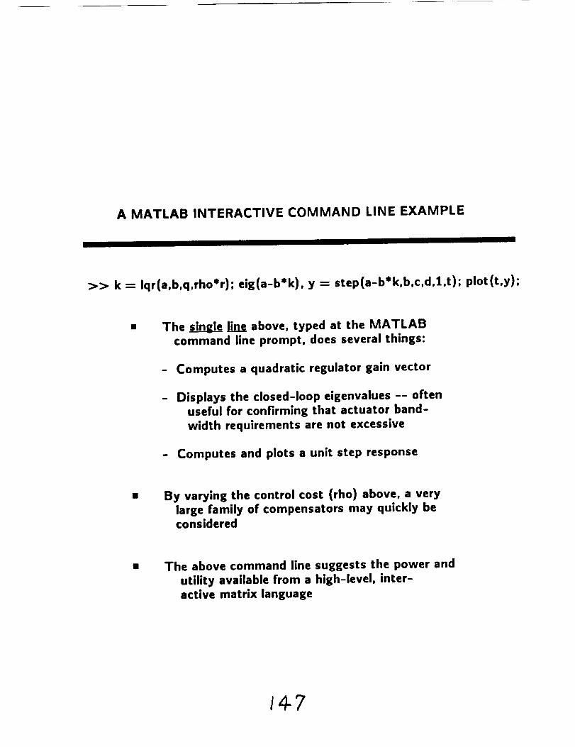
>> k = Iqr(a,b,q,rho*r); eig(a-b*k), y = step(a-b*k,b,c,d,l,t); plot(t,y);
The _ lin___eeabove, typed at the MATLAB
command line prompt, does several things:
- Computes a quadratic regulator gain vector
Displays the closed-loop eigenvalues -- often
useful for confirming that actuator band-
width requirements are not excessive
- Computes and plots a unit step response
By varying the control cost (rho) above, a very
large family of compensators may quickly beconsidered
The above command line suggests the power and
utility available from a high-level, inter-
active matrix language
147

PC-MATLAB/386 PROCESSING SPEED
• MATLAB's UNPACK Benchmark: 460 double precision KFLOPS
This processing speed is:
- 25 x faster than standard PC/AT- 6 x faster than Mac II
- :3 x faster than MicroVax II
Implication: the fast response time resulting from
such performance allows for truly interactive
design iterations on complex control laws

MATLAB EXTENSIBILITY
User-defined functions may be developedthrough creation of simple text files
Some typical user-defined functions:
- Frequency-response plotting routines
- Application-specific linear transformations
- Multivariable Nyquist criterion
Complex state-space or transfer-function
models also defined through user text files

AN EXAMPLE OF A USER-DEFINED COMMAND FILE
Below command set calculates and plots the
maximum and minimum singular values of
a plant and observer-based compensator,
for a loop broken at plant input
function [smln,smax] = svdlnput(s,b,c,kcon,kobs,w);
Jay = sqrt(-l);[nn.xx]=size(a); 12:eye(nn); [nE,xx]:size(cza*b); phi = '(s*i2-a)';for I = l:nc;
s = w(1)*jey; phieval = eval(phl);
gs = c/phlevallb; ks = kcon / (phleval+bSkcon+kobs_c) • kobs;xx=svd(ks*Es); smln(1)=xx(ng); saax(1)=xx(1);
end;
convert to dec$bels and plot output
smtn:20*loglO(sain); smax:20*loglO(smax);
semilogx(w,smln,w,smax,'r--'); trld;
tltle('Max end Min SinEular Values; Loop Broken at Plant Input ');
xlabel('Frequenc¥ (rad/sec)'); ylebel('Mairnitude (db)');
Procedure requires only eleven lines ofexecutable MATLAB code

CLASSICAL CONTROL CAPABILITIES
• Frequency response
• Rootlocus
• Nyquist plots
Development of dynamic compensators
(lead-lag, notch filters, etc)

MODERN CONTROL DESIGN EXAMPLE
Design plant describes tactical missile ata high-altitude flight condition
Design plant includes single-plane rigid-body dynamics and effect of first flexiblemode on sensed pitch rate
Objective is to develop an autopilot to trackcommanded accelerations
Design challenge is to achieve high closed-loopbandwidth in presence of low-frequencybending modes

DESIGN APPROACH
Establish design goals for closed-loopresponsiveness and stability
Develop full-state feedback (LQR) gainsfor design plant
Define linear observer to reconstruct full statevector
- Use "robust observer" design (Doyle and Stein,197g IEEE Transactions on Automatic Control)
- Adjust observer gains to recover original LQR
loop transfer in desired frequency range

DESIGN PLANT MODEL
II II I
Fifth-order state vector x; x = Ax + bu
• x--" [qr qr/s a/s qf/s qf]
First three state variables are associated with
rigid-body airframe; the last two describe
flexible mode dynamics
• Rate gyro measurement: [1 0 0 0 1] * x
• (Integrated) accelerometer measurement: [0 0 I 00] * x
A "-"
I1 0 -2.3557e+02 1.7967e+02 0 01
.O000e+O0 0 0 0 00 2,6158e+00 -1,9951e+00 0 00 0 0 0 1.0000e+O00 0 0 -2.4649e+04 -3.1400e+00 I
-j
b "_
'2"8031e+02
09.2587e-02
03.0723e÷02

SOME OBSERVATIONS ON DESIGN PLANT MODEL
Feedback of the first three states describes
a very standard (rigid-body) autopilot
topology, used by tactical missiles sincelgso's
Open-loop plant is characterized by lightly
damped airframe (weathercock) poles, and
by bending mode poles
- Airframe pole frequency lies atnominal 2.5 Hz
- Bending mode has nominal 25 Hz natural
frequency
Desired autopilot crossover frequency here
will lie near the bending mode frequency

EFFECT OF STRUCTURAL MODE ON SENSED PITCH RATE
(RATE GYRO MEASUREMENT)
Response to Unit Fin Deflection25 , ,.
2O
15
I0
_ 5
0
i_ -lo
-15
-2O
-250
t
I i i i I I I I i
0.1 0.2 0.3 0.4 0.5 0.6 0.7 0.8 0.9
Time (see)

CONTROLLABILITY AND OBSERVABILITY PROPERTIES OF PLANT
• System (A,b) is controllable
System is unobservable if rate gyro alone,or accelerometer alone, is used as the
measurement to reconstruct state vector
Both sensor outputs thus should be used in the
observer design
Approach taken for this application:
Define a (non-square) design plant having
one input (fin deflection) and two inde-
pendent outputs (gyro and accelerometer)
Use extensions of loop transfer recovery
(Williams and Madiwale, 1985 ACC) valid
for non-square systems

FREQUENCY RESPONSE OF FULL-STATE FEEDBACK (LQR) SYSTEM(LOOP BROKEN AT PLANT INPUT)
_D
=E
6O
4O
2O
-20
-4O
! !!!!
_60 i i * l llll, J t I i l llll I n a i I l I Ii l J i l J i i la
10-] 10 o 101 10 z 10 3
Frequency (rad/sec)

OBSERVATIONS ON LOOP TRANSFER RECOVERY PROCEDURE
For this application, recovery at both the(rigid-body) airframe and bending mode
frequencies may only be achieved with veryhigh observer gains
For practical ranges of observer gains, recovery
at airframe frequencies is obtained at the costof lessened robustness in the structural mode
frequency range
Use of a set of user-defined MATLAB files, to
implement a range of observer gain calcu-lations, makes evaluation of this robustness
tradeoff straightforward

RECOVERY OF DESIRED FULL-STATE FEEDBACK SYSTEMWITH MODEL-BASED COMPENSATOR
Asymptotic Loop Transfer Recovery Properties of Compensator100 ...................................................
°m
5O
-50
-100 ............ _"..... '-
i i i lillll i i i ii_lll i | i illlll ! 1 i Ila_tl J I , illll, i i i ii,
lO-I 10 o lOl 10 z IO s 10 4 IO s
Frequency (rad/sec)
160

ACCELERATION STEP RESPONSE OF FINAL COMPENSATOR DESIGN
Response to l-Gee Acceleration Command
0°_
>@
i i i i I I i
0.3 0.4 0.5 0.6 0.7 0.8 0.9
Time (see)
161

RESPONSE OF FLEXIBLE MODE STATE DURINGACCELERATION STEP RESPONSE
0.5
0.4
0.3
0.2
0.!
o-0.1
-0.2
-0.3
-0.4
-0.50
Pitch Rate Response Due to Flexible Mode
.............
I I I i I I ! I |
0.1 0.2 0.3 0.4 0.5 0.6 0.? 0.8 0.9 1
Time (sec)
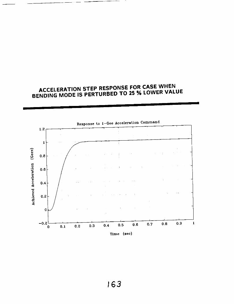
ACCELERATION STEP RESPONSE FOR CASE WHENBENDING MODE IS PERTURBED TO 25 % LOWER VALUE
1.2
Response to l-Gee Acceleration Command
I -
O_0.8
O
0.6
_ 0.4
0.2o_
(P
0
f/
_0.2___ .....0 0.1 0.2 0.3 0.4 0.5 0.6
Time (sec)
163

COMPARISON OF ACTUAL AND RECONSTRUCTED FLEXIBLEMODE STATE DURING STEP RESPONSE -- BENDING MODE
PERTURBED TO 25 % LOWER VALUE
I I I
0.5
0"4 t
0.3
0.2-
0.1
0
-0.1 i:'
lO*_ _' 'l
-0.3
-0.4
-0.50
Actual (-) and Reconstructed (--) Flexible Mode Statel i w J w w
f i _ / ,,_ ,....,, ,_ ,
i , I i I l I , i, I I
0.1 0.2 0.3 0.4 0.5 0.6 0.7 0.8 0.9
Time (sec)
SUMMARY OF DESIGN RESULTS
Model-based compensator yields a high-bandwidthautopilot, which is robust to at least a 25%
perturbation in bending mode frequency
• A number of issues still not addressed:
- Detailed noise sensitivity assessment
- Effect of higher-frequency structural modes
- Phase lag from actuator dynamics- Effect of structural modes on accelerometer
measurement
- Tolerance to uncertainties in aerodynamics
• Above concerns could also be addressed using MATLAB

SUMMARY: MATLAB APPLICABILITY FORCONTROL DESIGN OF FLEXIBLE SYSTEMS
MATLAB provides the necessary tools for avariety of control system design techniques
Extensibility of MATLAB allows developmentof tools to implement recent modern controldesign methods, including loop transferrecovery
Implementation for 80386-based machines (PC-MATLAB/386) has very high performance,allowing for interactive control design ofcomplex systems such as flexible structures
Any flexible structures control problem whichcan be cast into a state-space framework
may benefit from design work with MATLAB