n600 wireless dual band router wndr3400 setup manual - netgear
TRANSCRIPT

3Muscle and Forces
Physicists recognize four fundamental forces. In the order of their rel-ative strength from weakest to strongest they are: gravitational,electrical, weak nuclear, and strong nuclear. Only the gravitational andelectrical forces are of importance in our study of the forces affectingthe human body. The electrical force is important at the molecular andcellular levels, e.g., affecting the binding together of our bones and con-trolling the contraction of our muscles. The gravitational force, thoughvery much weaker than the electrical force by a factor of 1039, is impor-tant as a result of the relatively large mass of the human body (at leastas compared to its constituent parts, the cells).
3.1 How Forces Affect the Body
We are aware of forces on the body such as the force involved when webump into objects. We are usually unaware of important forces insidethe body, for example, the muscular forces that cause the blood to cir-culate and the lungs to take in air. A more subtle example is the forcethat determines if a particular atom or molecule will stay at a given place
37

in the body. For example, in the bones there are many crystals of bonemineral (calcium hydroxyapatite) that require calcium. A calcium atomwill become part of the crystal if it gets close to a natural place for cal-cium and the electrical forces are great enough to trap it. It will stay inthat place until local conditions have changed and the electrical forcescan no longer hold it in place. This might happen if the bone crystal isdestroyed by cancer. We do not attempt to consider all the variousforces in the body in this chapter; it would be an impossible task.
Medical specialists who deal with forces are (a) physiatrists (spe-cialists in physical medicine) who use physical methods to diagnose andtreat disease, (b) orthopedic specialists who treat and diagnose diseasesand abnormalities of the musculoskeletal system, (c) physical therapists,(d) chiropractors who treat the spinal column and nerves, (e) rehabili-tation specialists, and (f) orthodontists who deal with prevention andtreatment of irregular teeth.
3.1.1 Some Effects of Gravity on the Body
One of the important medical effects of gravity is the formation of vari-cose veins in the legs as the venous blood travels against the force ofgravity on its way to the heart. We discuss varicose veins in Chapter 8,Physics of the Cardiovascular System. Yet gravitational force on theskeleton also contributes in some way to healthy bones. When a personbecomes “weightless,” such as in an orbiting satellite, he or she losessome bone mineral. This may be a serious problem on very long spacejourneys. Long-term bed rest is similar in that it removes much of theforce of body weight from the bones which can lead to serious bone loss.
3.1. 2 Electrical Forces in the Body
Control and action of our muscles is primarily electrical. The forces pro-duced by muscles are caused by electrical charges attracting oppositeelectrical charges. Each of the trillions of living cells in the body hasan electrical potential difference across the cell membrane. This is aresult of an imbalance of the positively and negatively charged ions onthe inside and outside of the cell wall (see Chapter 9, Electrical Signalsfrom the Body). The resultant potential difference is about 0.1 V, butbecause of the very thin cell wall it may produce an electric field as
38 PHYSICS OF THE BODY

large as 107 V/m, an electric field that is much larger than the electricfield near a high voltage power line.
Electric eels and some other marine animals are able to add the elec-trical potential from many cells to produce a stunning voltage of severalhundred volts. This special “cell battery” occupies up to 80% of an eel’sbody length! Since the eel is essentially weightless in the water, it canafford this luxury. Land animals have not developed biological electri-cal weapons for defense or attack.
In Chapter 9 we discuss the way we get information about bodyfunction by observing the electrical potentials generated by the variousorgans and tissues.
3. 2 Frictional Forces
Friction and the energy loss resulting from friction appear everywherein our everyday life. Friction limits the efficiency of machines such aselectrical generators and automobiles. On the other hand, we make useof friction when our hands grip a rope, when we walk or run, and indevices such as automobile brakes.
Some diseases of the body, such as arthritis, increase the friction inbone joints. Friction plays an important role when a person is walking.A force is transmitted from the foot to the ground as the heel touchesthe ground (Fig. 3.1a). This force can be resolved into vertical and hor-izontal components. The vertical reaction force, supplied by the surface,is labeled N (a force perpendicular to the surface). The horizontal reac-tion component, FH, must be supplied by frictional forces. Themaximum force of friction Ff is usually described by:
Ff = µN
where N is a normal force and µ is the coefficient of friction betweenthe two surfaces. The value of µ depends upon the two materials in con-tact, and it is essentially independent of the surface area. Table 3.1 givesvalues of µ for a number of different materials.
The horizontal force component of the heel as it strikes the groundwhen a person is walking (Fig. 3.1a) has been measured, and found tobe approximately 0.15W, where W is the person’s weight. This is howlarge the frictional force must be in order to prevent the heel from slip-ping. If we let N≈W, we can apply a frictional force as large as f = µW.
Muscle and Forces 39
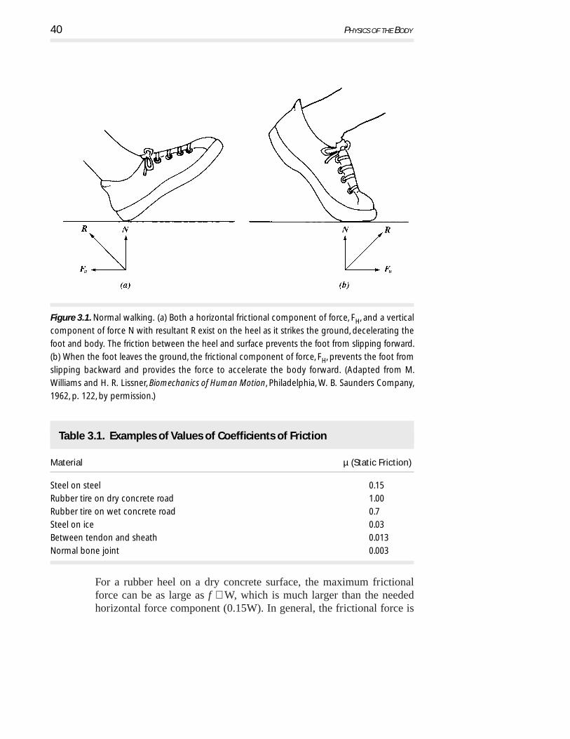
For a rubber heel on a dry concrete surface, the maximum frictionalforce can be as large as f ≅ W, which is much larger than the neededhorizontal force component (0.15W). In general, the frictional force is
40 PHYSICS OF THE BODY
Figure 3.1. Normal walking. (a) Both a horizontal frictional component of force, FH, and a vertical
component of force N with resultant R exist on the heel as it strikes the ground, decelerating the
foot and body. The friction between the heel and surface prevents the foot from slipping forward.
(b) When the foot leaves the ground, the frictional component of force, FH, prevents the foot from
slipping backward and provides the force to accelerate the body forward. (Adapted from M.
Williams and H. R. Lissner, Biomechanics of Human Motion, Philadelphia, W. B. Saunders Company,
1962, p. 122, by permission.)
Table 3.1. Examples of Values of Coefficients of Friction
Material µ (Static Friction)
Steel on steel 0.15
Rubber tire on dry concrete road 1.00
Rubber tire on wet concrete road 0.7
Steel on ice 0.03
Between tendon and sheath 0.013
Normal bone joint 0.003

large enough both when the heel touches down and when the toe leavesthe surface to prevent a person from slipping (Fig. 3.1b). Occasionally,a person slips on an icy, wet, or oily surface where µ is less than 0.15.This is not only embarrassing; it may result in broken bones. Slippingcan be minimized by taking very small steps.
Friction must be overcome when joints move, but for normal jointsit is very small. The coefficient of friction in bone joints is usually muchlower than in engineering-type materials (Table 3.1). If a disease of thejoint exists, the friction may become significant. Synovial fluid in thejoint is involved in lubrication, but controversy still exists as to its exactbehavior. Joint lubrication is considered further in Chapter 4.
The saliva we add when we chew food acts as a lubricant. If youswallow a piece of dry toast you become painfully aware of this lackof lubricant. Most of the large internal organs in the body are in moreor less constant motion and require lubrication. Each time the heartbeats, it moves. The lungs move inside the chest with each breath, andthe intestines have a slow rhythmic motion (peristalsis) as they movefood toward its final destination. All of these organs are lubricated bya slippery mucus covering to minimize friction.
3. 3 Forces, Muscles, and Joints
In this section we discuss forces in the body and forces at selected jointsand give some examples of muscle connections to tendons and bonesof the skeleton. Since movement and life itself depends critically onmuscle contraction, we start by examining muscles.
3. 3.1 Muscles and Their Classification
Several schemes exist to classify muscles. One widely used approach isto describe how the muscles appear under a light microscope. Skeletalmuscles have small fibers with alternating dark and light bands, calledstriations—hence the name striated muscle. The fibers are smaller indiameter than a human hair and can be several centimeters long. The othermuscle form, which does not exhibit striations, is called smooth muscle.
The fibers in the striated muscles connect to tendons and formbundles. Good examples are the biceps and triceps muscles depictedin Fig. 3.2, which will be examined further later in this section.
Muscle and Forces 41

Closer examination of the fibers show still smaller strands calledmyofibrils that, when examined by an electron microscope, consistof even smaller structures called filaments. The latter are composedof proteins. As shown schematically in Fig. 3.3, the filaments appearin two forms: (1) thick filaments that are composed of the proteinmyosin and are about 10 nm in diameter and 2000 nm (2 × 10⁻⁶ mor 2 micrometers) long, and (2) thin filaments that are composed ofthe protein actin and are about 5 nm in diameter and 1500 nm long.During contraction, an electrostatic force of attraction between thebands causes them to slide together, thus shortening the overall lengthof the bundle. A contraction of 15–20% of their resting length canbe achieved in this way. The contraction mechanism at this level isnot completely understood. It is evident that electrical forces areinvolved, as they are the only known force available. It should beemphasized that muscles produce a force only in contraction, that is,during a shortening of the muscle bundle.
Smooth muscles do not form fibers and, in general, are much shorterthan striated muscles. Their contraction mechanism is different, and insome cases they may contract more than the resting length of an indi-vidual muscle cell. This effect is believed to be caused by the slippingof muscle cells over each other. Examples of smooth muscles in the bodyare circular muscles around the anus, bladder, and intestines, and in thewalls of arteries and arterioles (where they control the flow).
42 PHYSICS OF THE BODY
Figure 3. 2. Schematic view of the muscle system used to bend the elbow. Biceps bend the elbow
to lift, triceps straighten it.

Sometimes muscles are classified as to whether their control is vol-untary (generally, the striated muscles) or involuntary (generally, thesmooth muscles). This classification breaks down, however; the blad-der has smooth muscle around it, yet is (usually) under voluntary control.
A third method of classifying muscles is based on the speed of themuscle’s response to a stimulus. Striated muscles usually contract intimes around 0.1 s (for example, the time to bend an arm), while smoothmuscles may take several seconds to contract (control of the bladder).
3. 3. 2 Muscle Forces Involving Levers
For the body to be at rest and in equilibrium (static), the sum of theforces acting on it in any direction and the sum of the torques about anyaxis must both equal zero.
Many of the muscle and bone systems of the body act as levers.Levers are classified as first-, second-, and third-class systems (Fig. 3.4).Third-class levers are most common in the body, while first-class leversare least common.
Third-class levers, however, are not very common in engineering.To illustrate why this is so, suppose you were to open a door whose
Muscle and Forces 43
Figure 3.3. Schematic view of actin and myosin filaments with arrows showing the sliding
movement between the filaments associated with muscle contraction.

doorknob was located close to the hinge side of the door. It requires acertain amount of torque to open the door. Recall that torque is the prod-uct of the applied force and a lever arm that describes the effect thisforce will have to produce rotation about the hinge. Since the lever armin this example is small, it follows that it will require a great deal offorce to open the door. Finally, note that the applied force in this exam-ple must move the door near the hinge only a short distance to open thedoor. In the case of humans, this type of lever system amplifies themotion of our limited muscle contraction and thus allows for larger (andfaster!) movement of the extremities. We give an example of movementof the forearm later in this section.
Muscles taper on both ends where tendons are formed. Tendons con-nect the muscles to the bones. Muscles with two tendons on one endare called biceps; those with three tendons on one end are called tri-ceps. Because muscles can only contract, muscle groups occur in pairs;one group serves to produce motion in one direction about a hinged joint,and the opposing group produces motion in the opposite direction. Therotation of the forearm about the elbow is an excellent example of thisprinciple. The biceps act to raise the forearm toward the upper arm,while the triceps (on the back of the upper arm) pull the forearm away
44 PHYSICS OF THE BODY
Figure 3.4. The three lever classes in the body and schematic examples of each. W is a force that
is usually the weight, F is the force at the fulcrum point, and M is the muscular force. Note that the
different levers depend upon different arrangement of the three forces, M, W, and F.

PR
OB
LEM
from the upper arm. Try this yourself a few times, feeling the action ofthese upper arm muscles with your other hand.
3.1 Try the following to experience the advantages and disadvantages ofa third-class lever system. Place a large plastic bucket on a table andload it with two 5 kg masses (weight, 98 N or 22 lb). Wrap the han-dle of the bucket with a cloth to provide a softer suspension point.Lift the bucket with one hand, keeping the angle between your fore-arm and upper arm about 90°. Now repeat the experiment of liftingthe bucket with the handle further up your forearm, say halfway tothe elbow. Can you feel the difference in the force required in yourbiceps? By how much has it changed by sense and by calculation(see below)? Repeat this experiment with varying angles between thetwo parts of your arm.
Let’s consider further the case of the biceps muscle and the radiusbone acting to support a weight W in the hand (Fig. 3.5a). Figure 3.5bshows the forces and dimensions of a typical arm. We can find the forcesupplied by the biceps if we sum the torques (force times distance—moment arm) about the pivot point at the joint. There are only twotorques: that due to the weight W (which is equal to 30W acting clock-wise) and that produced by the muscle force M (which actscounterclockwise and of magnitude 4M). With the arm in equilibrium4 M must equal 30 W, or 4 M – 30 W = 0 and M = 7.5 W. Thus, a mus-cle force 7.5 times the weight is needed. For a 100 N (~22 lb) weight,the muscle force is 750 N (~165 lb).
For individuals building their muscles through weight lifting, theexercise of lifting a dumbbell as in Fig. 3.5 is called a dumbbell curl.A trained individual could probably curl about 200 N (~44 lb) requir-ing the biceps to provide 1500 N (~330 lb) force.
In our simplification of the example in Fig. 3.5b, we neglected theweight of the forearm and hand. This weight is not present at a partic-ular point but is nonuniformly distributed over the whole forearm andhand. We can imagine this contribution as broken up into small segmentsand include the torque from each of the segments. A better method isto find the center of gravity for the weight of the forearm and hand andassume all the weight is at that point. Figure 3.5c shows a more correctrepresentation of the problem with the weight of the forearm and hand,H, included. A typical value of H is 15 N (~3.3 lb). By summing the
Muscle and Forces 45

torques about the joint we obtain 4 M = 14 H + 30 W, which simplifiesto M = 3.5 H + 7.5 W. This simply means that the force supplied bythe biceps muscle must be larger than that indicated by our first calcu-lation by an amount 3.5 H = (3.5)(15) = 52.5 N (~12 lb).
What muscle force is needed if the angle of the arm changes fromthe 90˚ (between forearm and upper arm) that we have been consider-
46 PHYSICS OF THE BODY
Figure 3.5. The forearm. (a) The muscle and bone system. (b) The forces and dimensions: R is the
reaction force of the humerus on the ulna, M is the muscle force supplied by the biceps, and W is
the weight in the hand. (c) The forces and dimensions where the weight of the tissue and bones
of the hand and forearm H is included. These forces are located at their center of gravity.

ing so far, as illustrated in Fig. 3.6a? Figure 3.6b shows the forces wemust consider for an arbitrary angle α. If we take the torques about thejoint we find that M remains constant as alpha changes! (As you willsee if you perform the calculation, this is because the same trigonometricfunction of α appears in each term of the torque equation.) However,the length of the biceps muscle changes with the angle. Muscle has aminimum length to which it can be contracted and a maximum lengthto which it can be stretched and still function. At these two extremes,the force the muscle can exert is much smaller. At some point inbetween, the muscle produces its maximum force (see Fig. 3.7). If thebiceps pulls vertically (which is an approximation), the angle of the fore-arm does not affect the force required; but it does affect the length ofthe biceps muscle, which in turn affects the ability of the muscle to pro-vide the needed force. Most of us become aware of the limitations ofthe biceps if we try to chin ourselves. With our arms fully extended wehave difficulty, and as the chin approaches the bar the shortened mus-cle loses its ability to shorten further.
Muscle and Forces 47
Figure 3.6. The forearm at an angle α to the horizontal. (a) The muscle and bone system. (b) The
forces and dimensions.

48 PHYSICS OF THE BODY
Figure 3.7. At its resting length L a muscle is close to its optimum length for producing force. At
about 80% of this length it cannot shorten much more and the force it can produce drops
significantly. The same is true for stretching of the muscle to about 20% greater than its natural
length. A very large stretch of about 2L produces irreversible tearing of the muscle.
Figure 3.8. Raising the right arm. (a) The deltoid muscle and bones involved. (b) The forces on the
arm. T is the tension in the deltoid muscle fixed at the angle α , R is the reaction force on the
shoulder joint, W1 is the weight of the arm located at its center of gravity, and W2 is the weight in
the hand. (Adapted from L. A. Strait, V. T. Inman, and H. J. Ralston, Amer. J. Phys., 15, 1947, p. 379.)

The arm can be raised and held out horizontally from the shoulderby the deltoid muscle (Fig. 3.8a); we can show the forces schematically(Fig. 3.8b). By taking the sum of the torques about the shoulder joint,the tension T can be calculated from:
T = (2 W1 + 4 W2)/ sin α (3.1)
If α = l6°, the weight of the arm W1 = 68 N (∼ 15 lb), and the weightin the hand W2 = 45N (∼ 10 lb), then T = 1145 N (∼ 250 lb). The forceneeded to hold up the arm is surprisingly large.
3. 2In the lever of the foot shown in Fig. 3.4, is M greater or smaller thanthe weight on the foot? (Hint: The muscle that produces M is attachedto the tibia, a bone in the lower leg.)
3. 3Show that for Fig. 3.6, the muscle force is independent of the angle.
3.4Derive Equation 3.1 for the arm and deltoid muscle system.
Muscle and Forces 49
PR
OB
LEM
PR
OB
LEM
PR
OB
LEM

3.5It is known that the human biceps can produce a force of approxi-mately 2600 N. Why can’t you pick up an object with your handwhich weighs 2600 N?
3.6 If you turn your hand over and press it against a table, you have afirst class lever system (see sketch). In this case, the biceps musclegroup is relaxed and is ignored. The force of the hand F on the tableis balanced by the force supplied by the triceps M pulling on the ulnaand the fulcrum force R located where the humerus makes contactwith the ulna. For the parameters shown below and for a force F =100 N (22 lb), find the force needed from the triceps. Ignore the massof the arm and hand.
3.7 One first-class lever system involves the extensor muscle, whichexerts a force M to hold the head erect; the force W of the weight ofthe head, acting at its center of gravity (cg), lies forward of the forceF exerted by the first cervical vertebra (see sketch on the next page).The head has a mass of about 3 kg, or weight W≅ 30 N.(a) Find F and M. [Answer: F = 48 N; M = 18 N](b)If the area of the first cervical vertebra, on which the head rests,
is 5 × 10⁻⁴ m2, find the stress (force per unit area: N/m2) on it.[Answer: 9.6 × 10⁴ N/m2]
50 PHYSICS OF THE BODY
PR
OB
LEM
PR
OB
LEM
PR
OB
LEM
M F
l
R
0.08l
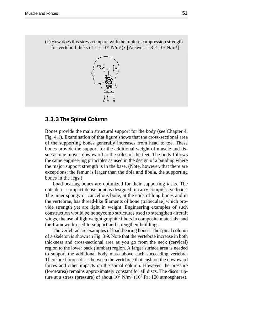
(c) How does this stress compare with the rupture compression strengthfor vertebral disks (1.1 × 10⁷ N/m2)? [Answer: 1.3 × 10⁶ N/m2]
Muscle and Forces 51
3. 3. 3 The Spinal Column
Bones provide the main structural support for the body (see Chapter 4,Fig. 4.1). Examination of that figure shows that the cross-sectional areaof the supporting bones generally increases from head to toe. Thesebones provide the support for the additional weight of muscle and tis-sue as one moves downward to the soles of the feet. The body followsthe same engineering principles as used in the design of a building wherethe major support strength is in the base. (Note, however, that there areexceptions; the femur is larger than the tibia and fibula, the supportingbones in the legs.)
Load-bearing bones are optimized for their supporting tasks. Theoutside or compact dense bone is designed to carry compressive loads.The inner spongy or cancellous bone, at the ends of long bones and inthe vertebrae, has thread-like filaments of bone (trabeculae) which pro-vide strength yet are light in weight. Engineering examples of suchconstruction would be honeycomb structures used to strengthen aircraftwings, the use of lightweight graphite fibers in composite materials, andthe framework used to support and strengthen buildings.
The vertebrae are examples of load-bearing bones. The spinal columnof a skeleton is shown in Fig. 3.9. Note that the vertebrae increase in boththickness and cross-sectional area as you go from the neck (cervical)region to the lower back (lumbar) region. A larger surface area is neededto support the additional body mass above each succeeding vertebra.There are fibrous discs between the vertebrae that cushion the downwardforces and other impacts on the spinal column. However, the pressure(force/area) remains approximately constant for all discs. The discs rup-ture at a stress (pressure) of about 107 N/m2 (107 Pa; 100 atmospheres).

52 PHYSICS OF THE BODY
Figure 3.9. The spinal column provides the main support for the head and trunk of the body. The
column has an “S” shape, and the vertebrae increase in cross-sectional area as the supporting load
increases. The length of the column for a typical adult male is about 0.7 m.

The length of the spinal column shortens slightly from its normallength of about 0.7 m (male) by as much as 0.015 m (1.5 cm = 0.6 in)after arising from sleep. The original length is restored after a night’ssleep. However, the spinal column does shorten permanently with agemost often as the result of osteoporosis and compression of the discs,which is particularly common in elderly women. Osteoporosis causesbone to weaken and eventually to collapse. This is discussed further inthe next chapter.
The spinal column has a normal curvature for stability. Viewed fromthe right side the lower portion of the spine is shaped like a letter “S”as shown in Fig. 3.9. Lordosis, kyphosis, and scoliosis are deviationsin the shape of the spine. Lordosis, too much curvature, often occurs inthe lumbar region. A person with this condition is sometimes calledsway-backed (Fig. 3.10a). Kyphosis is an irregular curvature of thespinal column as seen from the side; frequently it leads to a hump inthe back. A person with this condition is often referred to as hunch-backed (Fig. 3.10b). Scoliosis is a condition in which the spine curvesin an “S” shape as seen from the back (Fig. 3.10c). Normal posture isshown in Fig. 3.10d.
Muscle and Forces 53
Figure 3.10. Sketches for the abnormal spinal conditions of (a) lordosis (or sway-back), (b) kyphosis
(or hunch-backed), and (c) scoliosis. (d) The normal condition. (Adapted from A Guide to Physical
Examination, B. Bates, J. P. Lippincott, Philadelphia, PA, pp. 261–261, (1974) by permission.)

3.8 The discs in the spinal column can withstand a stress (force per unitarea) of 1.1 × 10⁷ N/m2 before they rupture.(a) If the cross-sectional area of your discs is 10 cm2, what is the max-
imum force that can be applied before rupture takes place?[Answer: 1.1 × 10⁴ N]
(b)Estimate the stress at a disc located at the level of the center ofgravity of your body when you are standing vertically. [Answer:3.5 × 10⁵ N/m2]
(c) What types of situations might the body experience where thestress on this vertebra would be much larger than in (b) above?
3. 3.4 Stability While Standing
In an erect human viewed from the back, the center of gravity (cg) islocated in the pelvis in front of the upper part of the sacrum at about 58%of the person’s height above the floor. A vertical line from the cg passesbetween the feet. Poor muscle control, accidents, disease, pregnancies,overweight conditions, or poor posture change the position of the cg toan unnatural location in the body as illustrated in Fig. 3.11. An overweightcondition (or a pronounced slump) lead to a forward shift of the cg, mov-ing the vertical projection of it under the balls of the feet where the balanceis less stable. The person may compensate by tipping slightly backward.
To retain stability while standing, you have to keep the vertical pro-jection of your cg inside the area covered by your feet (Fig. 3.12a). Ifthe vertical projection of your cg falls outside this area, you will tipover. When your feet are close together (Fig 3.12a) you are less sta-ble than when they are spread apart (Fig 3.12b). Likewise, if the cgis lowered, you become more stable. A cane or crutch also improvesyour stability (Fig. 3.12c). Comparing the stability of a human with afour-legged animal, it is clear that the animal is more stable becausethe area between its four feet is larger than for two-legged humans.Thus it is understandable that a human baby takes about ten monthsbefore it is able to stand while a newborn four-legged animal achievesthis in less than two days (in the wild, less than one hour), a usefulcondition for survival.
The body compensates its stance when lifting a heavy suitcase withone arm. The opposite arm moves out and the body tips away from theobject to keep the cg properly placed for balance. (Try lifting the bucketused in Problem 3.1 out to the side to see how this works.) People who
54 PHYSICS OF THE BODY
PR
OB
LEM

Muscle and Forces 55
Figure 3.11. (a) The center of gravity of a normal person is located about 58% of the person’s
height above the soles of their feet. (b) An overweight condition can shift the cg forward so that
the vertical projection of it passes underneath the balls of the feet, causing the body to
compensate by assuming an unnatural position leading to possible muscle strain. (After C. R. Nave
and B. C. Nave, Physics for the Health Sciences, W. B. Saunders Company, 1975, p. 24 by permission.)
Figure 3.12. The body remains stable as long as the vertical projection of the cg remains inside the
cross-hatched area between the feet. (a) The stable area when the feet are close together, (b) the
stable area when the feet are spread apart, and (c) the stable area when a cane or crutch is used.

have had an arm amputated are in a situation similar to a person car-rying a suitcase. They compensate for the weight of the remaining armby bending the torso; however, continued bending of the torso leads tospine curvature. A common prosthesis is an artificial arm with a massequal to the missing arm. Even though the false arm may not function,it helps to prevent distortion of the spine.
3. 3.5 Lifting and Squatting
The spinal cord is enclosed and protected by the spinal column. The spinalcord provides the main pathway for the transmission of nerve signals toand from the brain. The discs separating the vertebrae can be damaged;one common back ailment is called a slipped disc. The condition occurswhen the wall of the disc weakens and tears, leading to a bulge that some-times pushes against nerves passing through the special holes (foramina)on the sides of each vertebra. Extended bed rest, traction, physical ther-apies, and surgery are all used to alleviate this condition.
An often abused part of the body is the lumbar (lower back)region, shown schematically in Fig. 3.13. Lumbar vertebrae are sub-ject to very large forces those resulting from the weight of the bodyand also the forces you create in the lumbar region by lifting. Thefigure illustrates the large compressive force (labeled R) on the fifthlumbar vertebra (labeled L5). When the body is bent forward at 60°to the vertical and there is a weight of 225 N (∼ 50 lb) in the hands,the compressive force R can approach 3800 N (∼ 850 lb, or about sixtimes an average body weight).
It is not surprising that lifting heavy objects incorrectly is a primarycause of low back pain. Since low back pain can be serious and is notwell understood, physiologists are interested in finding out exactly howlarge the forces are in the lumbar region. Measurements of pressure inthe discs have been made by inserting a hollow needle connected to acalibrated pressure transducer into the gelatinous center of an interver-tebral disc. This device measures the pressure within the disc. Thepressures in the third lumbar disc for an adult in different positions areshown in Fig. 3.14a and 3.14b. Even when standing erect there is a rel-atively large pressure in the disc as a result of the combined effects ofweight and muscular tension. If the disc is overloaded as might occur inimproper lifting, it can rupture (or slip), causing pain either from the rup-ture or by allowing irritating materials from inside the disc to leak out.
56 PHYSICS OF THE BODY

Muscle and Forces 57
Figure 3.13. Lifting a weight. (a) Schematic of forces used. (b) The forces where T is an
approximation for all of the muscle forces and R is the resultant force on the fifth lumbar vertebra
(L5). Note that the reaction force R at the fifth lumbar vertebra is large. (Adapted from L. A. Strait,
V. T. Inman, and H. J. Ralston, Amer. J. Phys., 15, 1947, pp. 377–378.)

58 PHYSICS OF THE BODY
Figure 3.14. Pressure on the spinal column. (a) The pressure on the third lumbar disc for a subject
(A) standing, (B) standing and holding 20 kg, (C) picking up 20 kg correctly by bending the knees,
and (D) picking up 20 kg incorrectly without bending the knees. (b) The instantaneous pressure
in the third lumbar disc while picking up and replacing 20 kg correctly and incorrectly. Note the
much larger peak pressure during incorrect lifting. (Adapted from A. Nachemson and G. Elfstrom,
Scand. J. Rehab. Med., Suppl. 1, 1970, pp. 21–22.)

Muscle and Forces 59
It has been argued that low back pain is the price that humans payfor being erect; however, disc degeneration also occurs in four-leggedanimals (in particular, in dachshunds). Disc failures for both animals andhumans occur in regions under the greatest stress.
Just as forces can be transmitted over distances and around cornersby cable and pulley systems, the forces of muscles in the body are trans-mitted by tendons. Tendons, the fibrous cords which connect the muscleend to a bone, minimize the bulk present at a joint. For example, themuscles that move the fingers to grip objects are located in the forearm,and long tendons are connected to appropriate places on the fingerbones. Of course, the tendons have to remain in their proper locationsto function properly. Arthritis in the hands often prevents the tendonsfrom fully opening and closing the hands.
In the leg, a tendon passes over a groove in the kneecap (patella)and connects to the shin bone (tibia). With your leg extended you canmove the patella with your hand but with your knee flexed you cannot;the patella is held rigidly in place by the force from the tendon as shownin Fig. 3.15. The patella also serves as a pulley for changing the direc-tion of the force. This also acts to increase the mechanical advantageof the muscles that straighten the leg. Some of the largest forces in thebody occur at the patella. When you are in a deep squatting position,the tension in the tendons that pass over the patella may be more thantwo times your weight (Fig. 3.15).
3. 3.6 Forces on the Hip and Thigh
When you are walking, there is an instant when only one foot is on theground and the cg of your body is directly over that foot. Fig. 3.16ashows the forces acting on that leg. These forces are (1) the upward ver-tical force on the foot, equal to the weight of the body, W; (2) the weightof the leg, WL, which is approximately equal to W/7; (3) R, the reac-tion force acting between the hip and the femur; and (4) the tension, T,in the muscle group between the hip and the greater trochanter on thefemur. The latter provides the force to keep the body in balance.
The various dimensions and the angle shown in Fig. 3.16 have beentaken from cadaver measurements. Solving the equations for equilib-rium in this example, it is found that T = 1.6 W and R = 2.4 W at thehip joint. Thus for a 70 kg individual, the head of the femur experiencesa force of over 1600 N (≈350 lb) or 2.4 times the body weight!

When there is injury to the muscle group at the hip, or damageto the hip joint, the body reacts by trying to reduce the forces thatcause pain—T and R in Fig. 3.16a. It does this by tipping the bodyso that the cg is directly over the ball of the femur and the foot (Fig.3.16b). This reduces the muscle force, T, to nearly zero, and the reac-tion force, R, becomes approximately the body weight W minus oneleg, or (6/7) W. R is now pointing directly downward. This reducesthe forces T and R by a large amount and helps the healing process.However, the downward reaction force causes the head of the femurto grow upward, while the ball of the femur on the other leg does notchange. Eventually this leads to uneven growth at the hip joints andpossible permanent curvature of the spine.
60 PHYSICS OF THE BODY
Figure 3.15. Diagram of the tensile force on the patellar ligament during squatting. The tension T
is very large when a person is in a low squat.

Muscle and Forces 61
Figure 3.16. A diagram that shows approximately the forces and dimensions (in cm) for the hip-
leg under different conditions. (a) When the person is standing on one foot. The vertical upward
force on the foot is the person’s weight, W. The weight of the leg, WL, is taken to be W/7 and the
angle of the hip abductor muscles indicated by T is taken to be 70°. R is the reaction force
between the hip and the head of the femur (hip joint). (b) When either the hip joint or abductor
muscle is injured, the body is bent to place the cg directly over the ball of the femur and the
center of the foot, thus reducing the reaction force, R, and the force of the abductor muscle, T. (c)
When a cane is used, the abductor force, T, and the reaction force, R, at the head of the femur are
greatly reduced. The upward force of FC = W/6 gives T ≈ 0.65W and R ≈ 1.3W, a substantial
reduction from that of part (a). (Adapted from M. Williams and H. R. Lissner, Biomechanics of
Human Motion, Philadelphia, W. B. Saunders Company, 1962, p.110 and from G. B. Benedek and F.
M. H. Vilars, Physics with Illustrative Examples from Medicine and Biology, Vol. 1, Mechanics, Addison-
Wesley, 1973.)

PR
OB
LEM
The use of crutches or a cane reduces the force on the hip joint. Thephysics of the use of a cane is shown schematically in Fig. 3.16c. Thereare three forces acting on the body: the weight, W, the force, FC, push-ing upward on the cane, and the upward force on the foot equal to W − FC. Note that the cane is in the hand opposite to the injured hip.Without the cane, we found T = 1.6 W and R = 2.4 W. The use of thecane reduces these forces by allowing the foot to move from the posi-tion under the centerline of the body, as in Fig. 3.16a, to a new locationcloser to being under the head of the femur. The spine is not twisted asit is in Fig. 3.16b. The cane is located 0.3 m from the vertical projectionline of the cg. We assume that the cane supports about 1/6 of the body’sweight. For the conditions given in Fig. 3.16c, we find T = 0.65 W andR = 1.3 W. Although human nature leads us to hide our handicaps, theuse of a cane can considerably aid in the healing process for hip joints.
3.9Use the equations of static equilibrium to calculate the forces T andR for the case shown in Fig. 3.16a. [Answer: T = 1.6 W; R = 2.4 W]
3.4 Forces During Collisions
When a portion of the body (or the whole body) bumps into a solidobject, it rapidly decelerates, resulting in large forces. If we considerthe deceleration to be constant and limit ourselves to one-dimensionalmotion, we can use the original form of Newton’s second law. Forceequals the rate of change of momentum. The more common form, masstimes acceleration, can be written as:
F = ma = m(∆v/∆t) = ∆(mv)/∆t
or F = the rate of change of momentum.
Newton originally wrote his second law in this form.
62 PHYSICS OF THE BODY

3.4.1 Examples of Forces during Collisions
The following example illustrates how this form of Newton’s secondlaw can be used to estimate the forces on the body when it collides withsomething:
Example: A person walking at 1 m/s accidentally bumps her or his headagainst an overhanging steel beam (ouch!). Assume that the head stopsin about ∆t = 0.01 s while traveling an additional distance of 0.005 m(5 mm). The mass of the head is 3 kg. What is the force which causedthis deceleration?
Answer: The change of momentum is ∆(mv) = (3 kg)(0 m/s) −(3 kg)(1 m/s) = −3 kg m/s (the minus sign means that the momen-tum of the head has decreased; the force is in the opposite directionfrom the motion). Thus F = (−3 kg m/s)/(0.01 s) = −300 N (about67 lb force).
Example: If we repeat this accident, with a steel beam with 0.02 m (2cm) of padding, the time of deceleration is increased to ∆t = 0.04 s. What force acts to decelerate the head under these conditions?
Answer: F = ∆(mv)/∆t = (3 kg m/s)/(0.04 s) = 75 N (about 15 lb),a considerable reduction from the first case.
An example of a dynamic force in the body is the apparent increaseof weight when the heart beats (systole). About 0.06 kg of blood is givena velocity of about 1 m/s upward in a time of t = 0.1s. The upwardmomentum given to the mass of blood is (0.06 kg) (1 m/s) = 0.06 kgm/s; thus the reaction force to this movement of the blood is (0.06 kgm/sec)/(0.1 s) or 0.6 N (∼ 0.125 lb, or 2 oz). This is enough to producea noticeable jiggle on a sensitive spring-type scale (as noted in Chap-ter 1, Terminology, Modeling, and Measurement).
If you jump from a height of 1 m and land stiff-legged, you are infor a shock. Under these conditions, the deceleration of the body takesplace mostly through compression of the padding of the feet. We cancalculate that the body is traveling at 4.5 m/s (16 km/hr) just prior tohitting; and if the padding collapses by 1 cm, the body stops in about0.005 s (5 ms). Under these conditions, the force in your legs is almost100 times your weight (that is, 100 g; see Fig. 3.17). If you land on a
Muscle and Forces 63

gym mat, the deceleration time would be longer; and if you follow thenormal body reaction, you will land on your toes first and bend yourknees to decelerate over a much longer time, thus decreasing the land-ing force.
A current popular form of entertainment is bungee jumping, inwhich a person is attached to a very stretchable bungee cord and jumpsfrom a considerable height. The bungee cord decelerates the person overa long distance. The thrill comes from the freefall and deceleration. Interms used in Fig. 3.17, the deceleration distances would usually be morethan 10 m and the velocities below 100 km/hr. This puts the conditionsbeyond the upper right region of the figure.
64 PHYSICS OF THE BODY
Figure 3.17. A compilation of documented cases of impact results on humans shown as a log-log
plot of the velocity on impact versus the deceleration distance during impact. The diagonal lines
show the deceleration in terms of acceleration of gravity, g. (One g times your body’s mass is
equal to your body weight.) The hollow squares represent data from documented free-fall
survivors. The shaded areas represent guestimates for the other situations. (After R. G. Snyder,
Bioastronautics Data Book, Second ed., 1973, p. 228.)

PR
OB
LEM
3.10A 50 kg person jumping from a height of 1 m is traveling at 4.4 m/sjust prior to landing. Suppose the person lands on a pad and stops in0.2 s. What maximum decelerating force will be experienced?[Answer: Fmax = 1100 N]
3.4. 2 Surviving Falls from Great Heights
You might think that if you jump or fall from a great height your chanceof surviving is zero, unless of course you land on something like a giantairbag. In real life, your chances are very small, but not zero. Peoplehave survived falls from great heights. It all depends on where and howyou land! If you fall on bushes, tree branches, deep snow, or land onthe side of a hill, the deceleration forces you experience may be smallenough that you could survive. A summary of the hazardous ranges forimpact collisions is shown in Fig. 3.17 along with some documentedcases. This figure shows the velocity at the time of impact plotted ver-sus the distance needed to stop. One could equally well plot the velocityversus the time needed to stop, but usually the distance is more easilymeasured. The heavy diagonal lines in the figure indicate the deceler-ations in terms of the units of gravity, g = 9.8 m/s–2. For example, adeceleration of 10 g corresponds to a decelerative force equal to tentimes the weight of the object. The double line in the figure representsan estimate of the limit of survivability.
3.4. 3 Collisions Involving Vehicles
Collisions of high velocity, modern cars subject occupants to very largeaccelerative or decelerative forces. The results of these forces on the dri-ver and passengers can be broken bones, internal injuries, and death.
In the 1960s a federally mandated safety program for the automo-bile was begun. Even earlier, the military, NASA, and scientific groupswere studying the forces that the body could withstand. For small con-trolled forces, this study was conducted using human volunteers. Formore extreme limits, cadavers, dummies, or animals were used to deter-mine the tolerance ranges.
Muscle and Forces 65
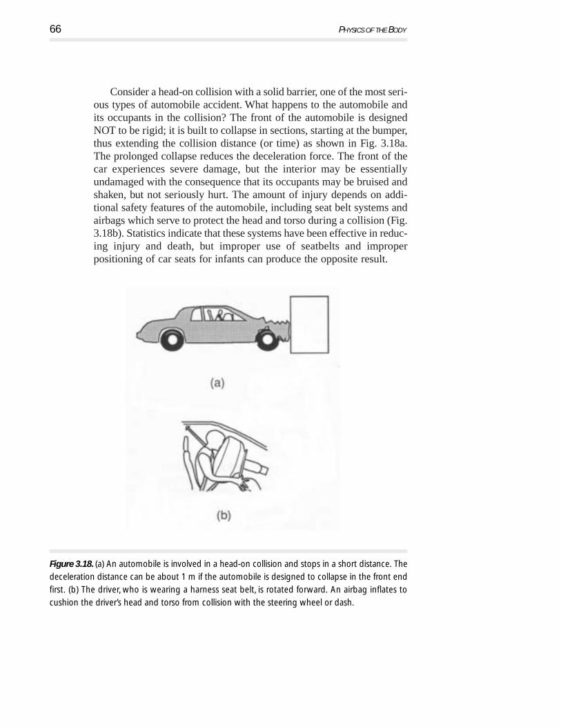
Consider a head-on collision with a solid barrier, one of the most seri-ous types of automobile accident. What happens to the automobile andits occupants in the collision? The front of the automobile is designedNOT to be rigid; it is built to collapse in sections, starting at the bumper,thus extending the collision distance (or time) as shown in Fig. 3.18a.The prolonged collapse reduces the deceleration force. The front of thecar experiences severe damage, but the interior may be essentiallyundamaged with the consequence that its occupants may be bruised andshaken, but not seriously hurt. The amount of injury depends on addi-tional safety features of the automobile, including seat belt systems andairbags which serve to protect the head and torso during a collision (Fig.3.18b). Statistics indicate that these systems have been effective in reduc-ing injury and death, but improper use of seatbelts and improperpositioning of car seats for infants can produce the opposite result.
66 PHYSICS OF THE BODY
Figure 3.18. (a) An automobile is involved in a head-on collision and stops in a short distance. The
deceleration distance can be about 1 m if the automobile is designed to collapse in the front end
first. (b) The driver, who is wearing a harness seat belt, is rotated forward. An airbag inflates to
cushion the driver’s head and torso from collision with the steering wheel or dash.

PR
OB
LEM
Because of the hazards of uncontrolled automobile collisions, federallaw requires a number of safety devices in automobiles. These includeheadrests, seat and shoulder belts (a three-point harness to prevent the per-son from being thrown from the automobile), energy-absorbing steeringcolumns, penetration-resistant windshields, and side door beams to pro-vide protection to the occupants during a side collision.
Information such as that given in Fig. 3.17 is used in the design ofemergency escape methods from high-performance aircraft and in safetydesigns for commercial aircraft as well as for automobiles. For exam-ple, if a pilot is to be shot upward through an escape hatch, it is necessaryto know the effects of acceleration in the seat-to-head direction. Byknowing the limitations of the body, the accelerative force and its dura-tion can be adjusted to minimize the probability of injury duringemergency procedures.
A more familiar example of the use of the information in Fig. 3.17is in the design of helmets for bicyclists, motorcycle riders, and for var-ious sports such as baseball, football, hockey, and lacrosse. Each helmetis designed to reduce deceleration by crushing during impact. One cri-terion for bicycle helmets is the ability of the rider’s head to withstanda 24 km/hr (15 mph) impact onto a rigid, flat surface as might happenif you fall when traveling at that speed. The helmet material must havethe appropriate stiffness to compression so that the collapse of the hel-met padding prolongs the deceleration and thus reduces the forces onthe head. One must remember, however, that safety devices do not pro-vide absolute protection.
3.11Estimate the force on the forehead in Fig. 3.18 if the mass of the headis 3 kg, its velocity is 15 m/s, and a padded dash is used instead ofthe air bag to stop the head in 0.02 s. [Answer: Fmax = 2.3 × 10³ N]
3.4.4 Effects of Acceleration on Humans
Acceleration of the body produces a number of effects such as (1) anapparent increase or decrease in body weight, (2) changes in internalhydrostatic pressure, (3) distortion of the elastic tissues of the body, and
Muscle and Forces 67

(4) the tendency of solids with different densities suspended in a liquidto separate. If the acceleration is sufficiently large, the body loses con-trol because it does not have adequate muscle force to work against thelarge acceleration forces. Under certain conditions the blood may poolin various regions of the body; the location of the pooling depends uponthe direction of acceleration. If a person is accelerated head first, thelack of blood flow to the brain can cause blackout and unconsciousness(see Chapter 8, Physics of the Cardiovascular System).
Astronauts in an orbiting satellite are in a condition of free fall orapparent weightlessness. Prior to man’s first space flights, there wereconcerns about the physiological effects of weightlessness. Many of theeffects predicted were based on changes observed in the body duringextended periods of bed rest. We now have information about the effectson the body of extended time in space. Some physiological changes dotake place; however, they have not been incapacitating or permanent.
Tissue can be distorted by acceleration and, if the forces are suffi-ciently large, tearing or rupture can take place. Laboratory informationis sparse, but some experiments in huge centrifuges have shown thattissue can be stretched by accelerative forces until it tears. In some autoaccidents, the aorta tears loose from the abdominal membrane leadingto serious consequences if not death.
3.4.5 Oscillatory Motion
When walking, the legs (and arms) undergo a repetitive motion similarto that of a pendulum. Using this observation, we can estimate the speedof walking at a natural pace. We model the motion of the leg as a sim-ple pendulum (ball at end of a string of length L) as illustrated in Fig.3.19. The leg differs from the simple pendulum in that the mass of theleg is distributed nonuniformly, whereas the mass of the simple pendu-lum is concentrated at one point. To correct for this difference, we definethe effective length of the leg, Leff, as that length of a simple pendulumthat would have the same period of oscillation as the complex shapedleg. (You might try to find this length by cutting out a model leg fromheavy cardboard or other material and comparing its oscillation periodwith that of a simple pendulum whose length you can adjust so as tomatch periods.) For small oscillation amplitudes, the period of a simplependulum is T = 2π(L/g)1/2, where g is the acceleration of gravity. Fora typical leg of a 2 m tall person, Leff = 0.2 m and thus T = 0.9 s. (Howdoes this agree with your natural walking pace? Remember, this is the
68 PHYSICS OF THE BODY
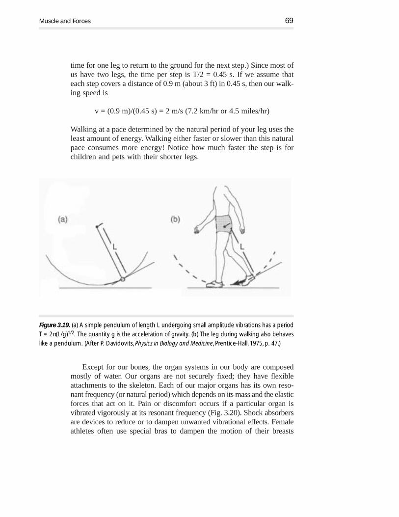
time for one leg to return to the ground for the next step.) Since most ofus have two legs, the time per step is T/2 = 0.45 s. If we assume thateach step covers a distance of 0.9 m (about 3 ft) in 0.45 s, then our walk-ing speed is
v = (0.9 m)/(0.45 s) = 2 m/s (7.2 km/hr or 4.5 miles/hr)
Walking at a pace determined by the natural period of your leg uses theleast amount of energy. Walking either faster or slower than this naturalpace consumes more energy! Notice how much faster the step is for children and pets with their shorter legs.
Except for our bones, the organ systems in our body are composedmostly of water. Our organs are not securely fixed; they have flexibleattachments to the skeleton. Each of our major organs has its own reso-nant frequency (or natural period) which depends on its mass and the elasticforces that act on it. Pain or discomfort occurs if a particular organ isvibrated vigorously at its resonant frequency (Fig. 3.20). Shock absorbersare devices to reduce or to dampen unwanted vibrational effects. Femaleathletes often use special bras to dampen the motion of their breasts
Muscle and Forces 69
Figure 3.19. (a) A simple pendulum of length L undergoing small amplitude vibrations has a period
T = 2π(L/g)1/2. The quantity g is the acceleration of gravity. (b) The leg during walking also behaves
like a pendulum. (After P. Davidovits, Physics in Biology and Medicine, Prentice-Hall, 1975, p. 47.)
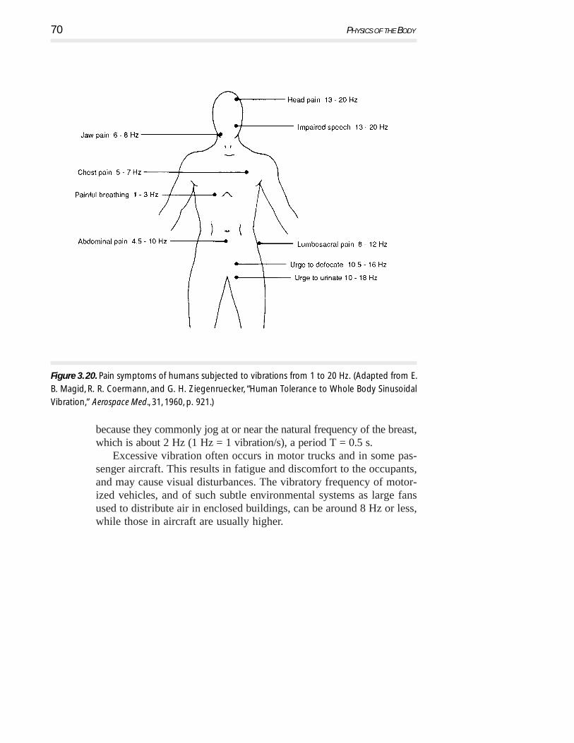
because they commonly jog at or near the natural frequency of the breast,which is about 2 Hz (1 Hz = 1 vibration/s), a period T = 0.5 s.
Excessive vibration often occurs in motor trucks and in some pas-senger aircraft. This results in fatigue and discomfort to the occupants,and may cause visual disturbances. The vibratory frequency of motor-ized vehicles, and of such subtle environmental systems as large fansused to distribute air in enclosed buildings, can be around 8 Hz or less,while those in aircraft are usually higher.
70 PHYSICS OF THE BODY
Figure 3. 20. Pain symptoms of humans subjected to vibrations from 1 to 20 Hz. (Adapted from E.
B. Magid, R. R. Coermann, and G. H. Ziegenruecker, “Human Tolerance to Whole Body Sinusoidal
Vibration,” Aerospace Med., 31, 1960, p. 921.)

3.5 Physics in Teeth
As we grow into adults, our teeth undergo changes that usually do notconcern us unless there is pain or expense. Toothaches and trips to thedentist cause concern, but most of the time our teeth play passive rolesin our lives.
There are many applications of physics in our teeth and jaws—suchas forces involved with biting, chewing, and erosion of teeth. In addi-tion, prosthetic (replacement) devices such as bridges and crowns haveto be biocompatible as well as have sufficient strength to function prop-erly. Sometimes we inherit less than perfectly arranged teeth. We usuallysee an orthodontist who uses a variety of procedures applying force toreposition and straighten the teeth.
We consider first the physics of normal teeth, the forces involved inbiting, and the force of the bite limited by the jaw (masseter) muscles.Next, we give simple examples of straightening and moving permanentteeth (orthodontics) and an example where the jaw is reshaped. Finally,we discuss a few prosthetic crowns and bridges.
3.5.1 Forces in Normal Teeth
Most of us wish we had teeth that were perfect. Figure 3.21 depicts thenormal 32 permanent adult teeth and a cross section of a typical per-manent molar tooth. It is obvious that different teeth have differentfunctions. The incisors and cuspids (sometimes called eye teeth orcanine teeth) have single cutting or biting edges. They have singleroots; the roots for the cuspids located in the upper jaw are the longest.Behind the cuspids are the first and second bicuspids, followed by threemolars, which usually have two or three roots. They are used for chew-ing or grinding food on the surface between the teeth (called the occlusalsurface). Figure 3.22 shows a schematic view of the skull. The pivotfor the jaw (mandible) is called the temporal-mandible joint (TMJ)—often a source of problems. The masseter muscle provides the main forcefor biting and chewing.
Scientists have measured the stress-strain behavior of the enamel anddentin components of teeth (see Chapter 4, Physics of the Skeleton, fordefinitions of stress-strain). A stress-strain curve for dentin is shown inFig. 3.23. The maximum force than one can exert, measured at the firstmolar occlusal surface (1st biscuspid), is about 650 N. If the area of
Muscle and Forces 71

72 PHYSICS OF THE BODY
Figure 3.21. (a) The 32 normal permanent teeth of an adult. (b) Cross-section view of an adult molar
tooth. (Images modified by Ken Ford, original image Copyright © 1994, TechPool Studios Corp. USA.)
(a)
(b)

Muscle and Forces 73
Figure 3. 22. Schematic view of an adult skull showing some of the teeth and the masseter muscle
that provides the closing and chewing action of the lower jaw (mandible). The dimensions are in
units of L which is the distance of the first bicuspid from the hinge of the jaw. 0.4L is the
approximate location of the masseter muscle from the hinge and 1.2L is the distance of the
central incisor from the hinge. The value of L is typically about 6.5 cm for women and 8 cm for
men. (Image modified by Ken Ford, original image Copyright © 1994, TechPool Studios Corp. USA.)
Figure 3. 23. The stress-strain curve for wet dentin
under compression for the premolar (bicuspids)
teeth for adults in two different age groups.
Young’s modulus initially increases with age, but
later it drops slightly. The enamel surface has a
Young’s modulus about five times greater than
that for dentin. Note the stress scale is a factor of
10 larger if given in N/mm.2 [After H. Yamada,
Strength of Biological Materials, F. H. Evans (ed.),
Baltimore, Williams and Wilkins, 1970, p. 150 by
permission.]

PR
OB
LEM
contact is about 10 mm2, the force per unit area is then nearly 65 N/mm2 (6.5 × 10⁷ N/m2 or kg/mm2). The Hooke’s law portion of thestress-strain curve in Fig. 3.23 in kg/mm2 for dentin shows about a 0.01(1%) fractional compression of the tooth. Considering that enamel isstronger than dentin by a factor of five, the biting force is well belowthat where failure of the tooth would occur.
If we accidentally bite into a hard cherry stone or kernel of popcorn,the area of contact may be as small as 1 mm2; then the compressive stressis about 650 N/mm2 (65 kg/mm2). Under these conditions, the toothwould fail. Many of us have learned this fact experimentally. A tooth thathas been weakened by fillings or decay might be broken when you bitea hard, small object.
The 650 N biting force is supplied by the masseter muscles. Goingback to Fig. 3.4 we see that biting is a third class lever with the mus-cle close to the fulcrum of the jaw as shown in Fig. 3.22.
3.12From the dimensions of Fig. 3.22 and the force on the first bicuspidof 650 N, show that masseter force is 1625 N and the force on thecentral incisors is 540 N.
Because the molars are used for grinding food, they have large sur-face areas compared to the incisors, which act more like knives in thebiting process. If the force from the masseter muscles were acting onlyon the central incisors and not on the molars, the net force would beless than 650 N by the ratio of L/1.2L or 540 N. This force is aboutequal to the weight of a small adult. You can imagine how effective theincisors would be when you visualize using a dull knife on an applewith a force about the same as the weight of a human.
Consider biting into an apple (see Fig. 3.24). The teeth behave likethe knife shown in (a). When the incisors first make contact with theapple, the stress (force/area) is very large because of the large appliedforce (assume 200 N) and the small area of the edge of the incisor teeth(perhaps 1 mm2). This applied force leads to a stress of 200 N/mm2
(20 × 107 N/m2), which is sufficiently large to rupture the apple (b) (andmost other foods as well!). Once the apple’s skin has been ruptured, then
74 PHYSICS OF THE BODY

PR
OB
LEM
the front and back surfaces of the teeth make contact with the interiorof the apple. The angle of the front incisors is about 60° as shown in(c) and (d) where the force of 200 N is still applied by the jaw on thefront teeth. In the simplest approximation (d), the downward force isbalanced by the two components of force F normal to the front and backsurfaces of the incisors. These two forces can be large and push apartthe two sides of the apple being bitten, causing the crack to spread.
3.13From the force diagram of biting in Fig. 3.24(d), estimate the forcesnormal to the two surfaces of the incisors.
Have you noticed that the permanent teeth of young adults appearvery prominent in their jaws? This is particularly true of the frontincisors. After 20 or 30 years this no longer seems to be the case. Whathas taken place is that the teeth wear; in some cases their length erodesas much as 0.1 mm/yr.
Muscle and Forces 75
Figure 3. 24. Schematic of the action of the biting behavior of an incisor tooth on an apple. (a) A
knife cutting into an apple. (b) The incisor making contact with the apple and having sufficient
force to cause the skin to rupture. (c) The incisor has penetrated the apple causing a crack to
propagate. (d) The schematic behavior of the forces on the incisors.

3.5. 2 Some Simple Cases of the Physics in Orthodontics
Everyone has seen a child with its thumb in its mouth. It is part of grow-ing up and nearly all children do this and eventually the thumb suckingends. Excessive thumb sucking can change the shape of the mouth as itcan move front teeth. Most often, the two central incisors are pushed outand spread apart, which can lead to a large overbite as shown in Fig. 3.25a.
76 PHYSICS OF THE BODY
Figure 3. 25. The location of the teeth in the upper jaw with respect to frontal teeth in the lower
jaw leads to several conditions: (a) overbite, (b) normal bite, and (c) crossbite. (Image modified by
Ken Ford, original image Copyright © 1994, TechPool Studios Corp. USA.)

Muscle and Forces 77
How can those teeth be brought back to the desired location? Oneway is shown in Fig. 3.26a where a mechanical connection is made tothe teeth that need to be moved and force is supplied by the external head-gear. Depending upon the initial conditions of the teeth, other methodssuch as adding a rubber band to provide tension between the teeth (shownin Fig. 3.26b) may be all that is needed to move the teeth together. Some-times a tooth needs to be moved a small amount; this can often beaccomplished by appropriate spring wires as shown in Fig. 3.26c. It issurprising how small the force needs to be, in this case only about 1 N.However, we should remember that in the early years, the erupting teethare guided by their surroundings: the jaw and the neighboring teeth.
Figure 3.26. (a) Sometimes in orthodontic work the teeth are moved by an external headgear which
supplies the force on the teeth. (b) For some teeth with too large a gap between them, the force of
a rubber band is sufficient. (c) A simple brace (stainless spring steel) arrangement used to provide a
small force (1–2 N) on a cuspid that needs to be moved into better alignment with the upper jaw.
(Images modified by Ken Ford, original image Copyright © 1994, TechPool Studios Corp. USA.)

There are many orthodontic appliances and, to a large degree, theydepend on the skill of the orthodontist. Figure 3.27 shows different meth-ods to apply forces to move teeth. Figure 3.27a represents a fixedorthodontic apparatus. It has several features common to straighteningand moving teeth, e.g., the banding and brackets are often used alongwith the arch wire to form the main support for other attachments tomove teeth. Clever arrangements of the attachment bands, arch wire,and elastic bands can accomplish complicated movements of the teeth.Figure 3.27b depicts an adjustable, removable appliance designed towiden the jaws and straighten the front teeth. The adjustment movesabout 0.8 mm per turn where each day one quarter of a turn is made.The total movement may be as much as one cm.
3.14Using Fig. 3.27a, give a descriptive discussion of the force directionsand the desired changes for the teeth being moved or straightened.
Figure 3.28 shows two examples of moving teeth: (a) A springunder compression is used to widen the space for the middle tooth. (b)A spring under tension moves a tooth to close a gap. These springs sup-ply a variable force for compression or expansion. Typically, the forcewill be about 1 N, which reduces as the tooth moves. Note that thesprings are connected to the brackets attached to the teeth. The bracketon the tooth to be moved can slide guided by the arch wire; the otherbracket is fixed to the arch wire.
3.5. 3 Crowns, Bridges, and Implants
Despite our efforts to preserve our teeth, an accident can lead to bro-ken teeth, or one or more teeth have decayed. We may be unfortunateand inherit genes that do not favor long-lasting teeth. Many people need
78 PHYSICS OF THE BODY
PR
OB
LEM

Muscle and Forces 79
Figure 3. 27. Two schematic orthodontic arrangements. (a) An exaggerated case of a fixed
orthodontic apparatus used to move and control teeth in the upper and lower right jaw (left side
not shown). (b) An adjustable movable appliance used to widen the upper jaw while at the same
time straightening the front teeth. This arrangement, when modified, can also be used to reduce
the size of the jaw. (Adapted from S. Garfield, Teeth, Teeth, Teeth, New York, Simon & Schuster, 1969,
p. 217 by permission.)
(a)
(b)
(a)

dental repair for damaged or missing teeth. The simplest repair is a sim-ple filling. In many cases the filling does not significantly reduce thestrength of the tooth; the repair may last a lifetime if properly done andgiven proper care.
Let us consider a more drastic case where the tooth has had exten-sive fillings and now is not structurally sound. How can one preservethe tooth and the function it provides? One approach is to crown thetooth, as shown in Fig. 3.29. This is a prosthesis and involves grindingaway the damaged area of the tooth and replacing it with an artificialtooth. The shape of the crown is determined from molds made of thepatient’s mouth, ensuring a custom fit. The crown is often made of astrong gold alloy with a porcelain face, in a color matching the perma-nent teeth and cemented in place. The use of gold is not a new idea theEtruscans, over 3000 years ago, made simple crowns. We now know thatgold is inert chemically; it has a strength greater than the original teethand can easily be cast in a mold. These repairs are attractive, functional,easy to keep clean, and long lasting.
80 PHYSICS OF THE BODY
Figure 3. 28. (a) A compressed spring arrangement is used to move an improperly aligned tooth
to a different position. (b) A spring under tension supplies a force to move a tooth to fill a gap.
(a)
(b)

Suppose that the tooth has been damaged so much that it needs tobe removed. You might be faced with the prospect of a “bridge” pros-thesis. For this to work, there have to be teeth on both sides of themissing tooth for attaching the bridge. Figure 3.30 shows an exampleof a bridge which uses the adjacent teeth.
A bridge may fail when the material properties of the gold alloy areimproperly used, such as an improper design with insufficient strengthbetween the replacement tooth and its attachment to the neighboringteeth. If the cross-sectional area on both sides of the replacement toothis insufficient, then the use of the bridge in chewing could cause thereplacement tooth to flex eventually breaking the connections. Engineerscall this a shearing force, which is another way of classifying thestrength of materials.
What happens if a nearby tooth cannot be used for a support? Fig.3.31 shows an implanted peg screwed directly into the jaw. The prosthetic tooth is then cemented to the peg. This type of prosthesis ismore difficult to keep clean, but acceptable in many situations.
Muscle and Forces 81
Figure 3. 29. (a) A tooth damaged by decay. (b) The damaged tooth is prepared for a crown. An
impression of the natural teeth is used to prepare the crown replacement. (c) Shows the crown
cemented in place. (Image modified by Ken Ford, original image Copyright © 1994, TechPool
Studios Corp. USA.)

82 PHYSICS OF THE BODY
Figure 3.30. A simple bridge prosthesis. (a) The missing tooth and the teeth on either side
prepared by grinding to support the bridge. (b) The bridge replacement and the supporting
structures for either side of the missing tooth. A mold of the region of the missing tooth and of
the teeth in the upper and lower jaw is needed to ensure the correct fit as shown in (c) for the
bridge cemented into place. (Adapted from S. Garfield, Teeth, Teeth, Teeth, New York, Simon &
Schuster, 1969, p. 257 by permission.)
Figure 3.31. In a situation where there are no adjacent teeth to use for a bridge, sometimes an
implant is used instead. (a) The implant is screwed into the jaw and the tissue and jaw are allowed
to heal. (b) Later, the peg to hold the tooth is installed. (c) The finished tooth cemented in place.
(Image modified by Ken Ford, original image Copyright © 1994, TechPool Studios Corp. USA.)

Of course, the materials for tooth repair need to be biocompatible.That is not a problem. Metals are often used to strengthen a body part(e.g., the hip transplant). The forces on prosthetic teeth go directly tothe jaw like natural teeth. An implanted tooth is a very successful prosthesis.
Muscle and Forces 83
