n iz case fi le copy - nasa · the results of the tests indicate that when the aspect ratio is ......
TRANSCRIPT

o_o0
O
O
1
CASE Fi LECOPY
N IZ 53835
NATIONAL ADVISORY COMMITTEE
FOR AERONAUTICS
TECHNICAL NOTE
No. 1835
INVESTIGATION AT LOV_ SPEEDS OF THE EFFECT OF ASPECT
RATIO AND SWEEP ON ROLLING STABILITY
DERIVATIVES OF UNTAPERED WINGS
By Alex Goodman and Lewis R. Fisher
Langley Aeronautical Laboratory
Langley Air Force Base, Va.
Washington
March 1949
FILE OOPYITobercurr_l
the _les of the Nat/enal
Ad,isory _tee
for,+,em+mt+tmWs+l_nt_tm,_, C,
+
https://ntrs.nasa.gov/search.jsp?R=19930082522 2018-06-20T21:37:40+00:00Z

NATIONAL ADVISORY COMMITTEE FOR AERONAUTICS
TECHNICAL NOTE NO. 1835
INVESTIGATION AT LOW SPEEDS OF TEE EFFECT OF ASl_ECT
RATIO AND SWEEP ON ROLLING STABILITY
DERIVATIVES OF UNTAPERED WINGS
By Alex Goodman and Lewis R. Fisher
SUMMARY
A low-scale wind-tunnel investigation was conducted in rolling flow
to determine the effects of aspect ratio and sweep (when varied independ-
ently) on the rolling stability derivatives for a series of untapered
wings. The rolling-flow equipment of the Langley stability tunnel was
used for the tests.
The results of the tests indicate that when the aspect ratio is
held constant, an increase in the sweepback angle causes a significant
reduction in the damping in roll at low lift coefficients for only the
higher aspect ratios tested. This result is in agreement with available
swept-wing theory which indicates no effect of sweep for aspect ratios
near zero. The result of the linear theory that the damping in roll is
independent of lift coefficient and that the yawing moment and lateral
force due to rolling are directly proportional to the llft coefficient
was found to be valid for only a very limited lift-coefficlent range
when the wings were highly swept. For such wings, the damping was
found to increase in magnitude and the yawing moment due to rolling, to
change from negative to positive at moderate lift coefficients.
The effect of wing-tlp suction, not accounted for by present theory,
was found to be very important with regard to the yawing moment due to
rolling, particularly for low-aspect-ratio swept wings. An empirical
means of correcting present theory for the effect of tip suction is
suggested.
The data of the present investigation have been used to develop a
method of accounting for the effects of the drag on the yawihg moment
due to rolling throughout the lift range.
INTRODUCTION
In order to estimate the dynamic flight characteristics of an air-
plane, a knowledge of the stability derivatives is necessary. The static-
stability derivatives are easily determined from conventional wind-tunnel

2 NACATN No. 1835
tests. The rotary derivatives, howewer, have usually been estlmate_ inthe past from available theory because of the lack of a convenientexperimental technique. Such a technique has been developed, and therotary derivatives can now be easily d_termlned by the utilization ofthe curved-flow and rolling-flow equil_ent in _he Langley stabilitytunnel. This equipment is being utilized for the purpose of determiningthe effects of various geometric variables on the rotary and staticstability characteristics of wings and complete airplane configurations.The method of determining the rolling derivatives by means of the rolling-flow equil_ent is described in reference 1.
The present paper gives results of tests madeto determine theeffects of independent variations of aspect ratio and sweepon the rollingderivatives of a series of untapered wings. The static and yawing deriva-tives determined for the samewings are reported in reference 2. Dataobtained in the present investigation have been used to derive an empiricalcorrection to existing theory for evaluation of the derivative of yawingmomentdue to rolling.
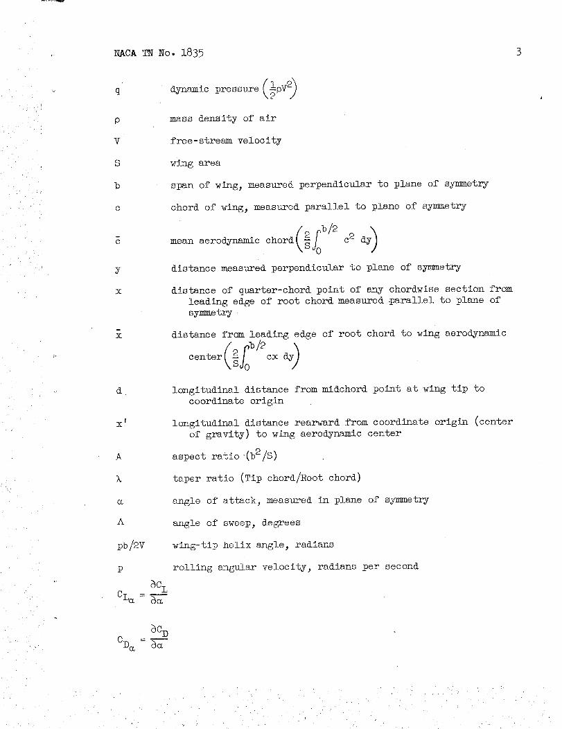
SYMBOIS
The data are presented in the form of standard NACAcoefficients offorces and moments, which are referred in all cases to the stability axeswith the origin at the quarter-chord point of the meanaerodynamic chordof the models tested. The positive directions of the forces, moments,and angular displacements are shown in figure 1. The coefficients andsymbols used herein are defined as follows:
CL
CD
Cy
C_
Cn
lift coefficient (L/qS)
drag coefficient (-X/qS)
lateral-force coefficient (Y/qS)
rolling-moment coefficient (L'/qSb)
yawing-momentcoefficient (N/qSb)
L lift
X longitudinal force
Y lateral force
Z normal force
L ! rolling moment
N yawing moment
NACATN No. 1835
q dynamic pressure (lpV 0
p mass density of air
V free- stream velocity
S wing area
b span of wing_ measuredperpendicular to plane of symmetry
c chord of wing_ measured parallel to plane of symmetry
/2 , b/2mean aerodynamic chord _ J0 c2dy)
y distance measured perpendicular to plane of symmetry
x distance of quarter-chord point of any chordwise section from
leading edge of root chord measured parallel to plane of
symmetry
x distance from leading edge of root chord to wing aerodynamic
center _ cx i
d longitudinal distance from mldchord point at wing tip to
coordinate origin
x longitudinal distance rearward from coordinate origin (center
of gravity) to wing aerodynamic center
A aspect ratio (b2/S)
k taper ratio (Tip chord/Root chord)
angle of attack, measured in plane of symmetry
A angle of sweep, degrees
pb/2V wing-tip helix angle_ radians
p rolling angular velocity_ radians per second
8C L
CL_- 8_
8C D
CD_- _

4 NACATN No. 1835
3C n
Cnp- _(_/
APPARATUS AND TESTS
The tests of the present investigation were conducted in the 6-foot-
diameter rolling-flow test section of the Langley stability tunnel. In
this test section, rolling flight is simulated by rotating the air stream
about a rigidly mounted model. (See reference 1.)
The models tested consisted of a series of untapered wings, all of
which had NACA 0012 airfoil sections in planes normal to the leading edge.
The model configurations are identified by the following designations:
Wing
1
2
3
4
56
789
Aspect ratio
1.34
1.34
i .34
2.61
2.612.61
5.16
5.165.16
Sweepback
(deg)
0
4560
0
4560
0
4560
The wing plan forms and other pertinent model data are presented
in figure 2.
The models were rigidly mounted on a single strut at the quarter-
chord point of the mean aerodynamic chord° (See fig. 3-) The forces and
moments were measured by means of electrical strain gages mounted on the
strut.

• j'
• • ! i• / _
ii!_
NACA TNNo. 1839
All of the tests were made at a dynamic pressure of 39.7 pounds per
square foot (Mach number of 0.17) with the exception of the tests made
on wing 9. The tests on this wing were made at a dynamic pressure of
24.9 pounds per square foot (Mach number of 0.13) because of the flexi-
bility of the model. The Reynolds numbers for these tests are presented
in table I. In the present investigation, tests were made through a
range of rotor speeds corresponding to the values of pb/2V given in
table I. Each model was tested through an angle-of-attack range from
approximately zero lift up to and beyond maximum lift.
As part of this investigation_ She effects of sharp-nose airfoil
sections on the rotary derivatives were also determined. The sharp-nose
airfoil sections were simulated by attaching full-span leading-edge
spoilers to wings i and 4 (fig. 2).
CORRECTIONS
Corrections for the effects of Jet boundaries_ based on unswept-
wing theory, have been applied to the angle of attack, drag coefficient,
and rolling-moment-coefficient data.
No corrections for the effects of blocking, turbulence, or for the
effects of static-pressure gradient on the boundary-layer flow have been
applied.
RESULTS ANDDISCDBSION
Presentation of Data
The results of the present series of tests are presented in figures 4
to 17. The lift coefficient and drag coefficient not ideally associated
°2with lift CD _A for the present series of wings are presented in
figure 4 and were obtained from tests of reference 2. The rolling
stability characteristics for the wings with and without spoilers are
given in figures 5 to 8. The development of the method used to calculate
the yawing moment due to rolling throughout the lift range is presented
in figures 9 to 15. A comparison between the experimental and calculated
values of the yawing moment due to rolling is given in figures 16 and 17.
Damping in Roll
Results obtained for the damping in roll (fig. 5) show that for the
low-aspect-ratio wings (A = 1.34 and 2.61) variations in the sweep angles
produced rather irregular effects. At the lowest aspect ratio, the damping
in roll of the wings with 45 ° and 60 ° sweepback was greater than that of

6 NACATN No. 1835
the unswept wing, and the difference was greater at high lift coefficientsthan at low lift coefficients. For an aspect ratio of 2.61_ the dampingin roll increased abruptly at lift coefficients of about 0.3 and 0.6 forthe 60° and 45° sweptback wings, respectively; whereas, no abrupt changewas noted for the unswept wing except at maximumlift. The abrupt changesin damping in roll occur at approximately the lift coefficients at which
C_2 (See fig. 4(b).)the drag increment CD - _-- begins to increase.Changesin the damping in roll (as well as in other rotary and staticderivatives) might be expected because an increase in the incre-
CL2ment CD _A should correspond to the beginning of flow separationfrom somepoint on the wing surface. Appreciably sharper breaks in the
curves of CD CL2- _ were obtained for the sweptback wings having an_A
aspect ratio of 5.16. (See fig. 4(c).) The breaks occur at lift coeffi-cients of about 0.3 and 0.5 for the wings with 60° and 45° sweepback_respectively, which are in fair agreement with the lift coefficients atwhich breaks occnr in the damping-in-roll curves (fig. 5).
An increase in Reynolds number, which would delay separation and
consequently cause the increases in CD - --CL2 to occur at higher liftxA
coefficients_ probably would also extend the linear portions of thecurves of damping in roll and of the other rotary derivatives.
The experimental values of CZp for CL = 0 determined from thesetests are compared with the theoretical values obtained from the approxi-
mate theory of reference 3and by an application of the theory of
Weissinger as presented in reference 4. (See fig. 6.) The variation
of CZp for CL = 0 as given by reference 3 is
(A + 4)c°sA _ p)ACZp = A + 4 cos A Z =0 o
where _Zp)A=0O for CL = 0 is obtained from the best available theory\ /--
or experimental data. A section-lift-curve slope of 5.67 per radian was
used for both the Weissinger and approximate theory computations. In
general, the experimental data compare about equally well with either ofthe theories. Both theories indicate a decreased effect of sweep as the
aspect ratio is reduced, although the variations indicated by reference 4
appear to be somewhat more reliable than those indicated by reference 3,
particularly at low aspect ratios.
Full-span leading-edge spoilers tested on two unswept wings (wings i
and 4) had little effect on CZp over a greater part of the lift range.

NACATNNo. 1835 7
(See fig. 7-) At high lift coefficients, a definite reversal in the signof CZp was obtained slightly before maximumlift was reached. A rever-sal in the sign of CZp for the wings without spoilers could not beestablished because near maximumlift the model vibrated so severely thataccurate measurementscould not be made.
Lateral Force Due to Rolling
The derivative Cyp varies linearly with lift coefficient in mostcases for only a limited range of lift coefficients. (See fig. 8.) The
lift are compared in figure l0 with valueszeroslopes Cyp/CL throughobtained by the approximzte theory of reference 3. Both theory andexperiment indicate an increase in slope with sweepfor constant aspectratio. The agreement between theory and experiment is poor, however, atthe lower aspect ratios. The theory of reference 3 does not account forthe values of Cyp/CL_ obtained at zero sweep. These values are presumedto be caused by tip suction (analogous to leading-edge suction discussedin reference 5)- _or the wings considered, the effect of tip suctionappears to be approximately independent of the sweepangle, because thedifferences between the experimental and theoretical curves are almostthe sameat all sweepangles, although the magnitude of the differenceincreases appreciably as the aspect ratio is reduced. The theory of low-aspect-ratio triangles presented in reference 5 indicates that the con-tribution of tip suction to the derivative Cyp varies inversely as theaspect ratio° If the samerelationship is assumedto apply to the pre-sent wings, an empirical expression for the effect of tip suction can bedetermined by plotting Cyp/CL for zero sweepagainst I/A. Such aplot, obtained from the present data and from unpublished data on atapered wing, is presented in figure 9. The data fall consistentlybelow the curve indicated by reference 5 for low-aspect-ratio trianglesbut are in fair agreementwith the following empirical expression:
(i)
When this increment is added to the contribution caused by sweep, as
given in reference 3, the following equation results:
__Cyp= A + cos A tan A + _i
CL A + 4 cos A A
(2)
Results calculated from equation (2) are compared in figure i0 with
the experimental results. The fact that good agreement is obtained is
of little interest, since the same experimental results were used to
evaluate the empirical correction included in equation (2). The most

8 NACATN No. 1835
important application of the tip-suction increment of Cyp is inconnection with the derivative Cnp as discussed in the followingsection.
Yawing MomentDue to Rolling
For the unswept wings without spoilers, wings 4 and 7, the variationof Cnp with lift coefficient was approximntely linear up to maximum
lift coefficient. The variation of Cnp with lift coefficient for wing i(without spoiler) was linear for only the low-lift-coefflcient range.(See fig. ii.) The sharp leading-edge wings, as simulated by attachingfull-span leading-edge spoilers to wings i and 4, yielded about the samevalues of Cnp at low lift coefficients as whenno spoilers wereattached. (See fig. 7.) At moderate lift coefficients, the spoilerscaused a reversal in the sign of Cnp, and Cnp becamepositive. Thisvariation is similar to the variation obtained with the swept wings.(See figs. 7 and ii.)
The values of Cnp for the swept wings were proportional to thelift coefficient for only a limited range. At moderate lift coeffi-cients, Cnp reversed sign and ass1_medcomparatively large positivevalues. This change probably results from the high drag associatedwith partial separation. Also, the initial slope Cnp/CL (fig. 13)increases as the aspect ratio decreases. The theory of references 3 and 6indicates the opposite variation. A possible explar_tion for the observedtrend might be that the tlp-suction contribution to the lateral forcealso contributes to the yawing moment. If the resultant tip-suctionforce is assumedto act at the mldchord point of the wing tip, a correc-tion to Cnp can easily be derived from the empirical expression pre-viously obtained for the tip-suction force. The correction is
where Cyp/CL for A = 0° is given by equation (i) and d, the longi-tudinal distance from the mldchord point at the wing tip to the coordinateorigin, is
d =-_ tan A+ _A + x'

NACATN No. 1835 9
where x' is the longitudinal distance rearward from the coordinate
origin (center of gravity) to the wing aerodynamic center. Therefore_
for untapered wings
ACnp l(tan i) i xCT - V_ A + X A2(3)
which when added to equation (31) of reference 3 gives
QZ_CnP)I _ A + 4
CL A + 4 cos A + 6 A 19 CT,
_A<tanA+l)- 1 x'A 2
(4)
/. \
The quantity qCnp/CL) 0 was given as [Cnp/CL)A=oO in reference 3,
but the new symbol is used herein since this quantity does not include
tip suction. (Equation (3) does not reduce to zero at A =0 °.)
Equation (4) has been used to construct the chart shown in figure 12.I^_%
The symbol k_OnPJ 1 indicates that the chart applies only to that part
CL
of Cnp contributed by the lift and induced-drag forces. Figure 13
shows a comparison of the experimental and calculated values of Cnp/CL.
The revised equation results in appreciable improvement over the
equation of reference 3- The agreement is very good for all the wings
tested.
As indicated by figure ii the curves of Cnp against CL are
linear over only a small range for the swept wings because of the rise
in drag at high lift coefficients. An equation which includes considera-
tion of the effect of the drag for unswept wings is given in reference 7
as
Cnp =-K(CL- CD_ ) (5)
where the value of K depends on the plan form of the wing. If the
induced drag is separated from the profile drag, equation (5) can be
written as
Cnp -KC L\I - 2 _A(6)

i0 NACA TN No. 1835
where
CD = D /
For swept wings, the first term of equation (6) can presumably be
replaced by equation (4) and, therefore,
_Z_CnP)I CL+ K(CDo_ _ (7)Cnp = CL
The increment of Cnp not associated with the lift or induced-
drag forces, therefore, can be expressed as
(ACnp)2 = K(CD0 )(8)
The value of the constant K can be evaluated empirically,
since (CDn _ can be obtained by measuring the slopes of the curves\ v/
CL2
of CD _A plotted against angle of attack in figure 4, and
<AC np) 2 = Cnp - ¢ACnp) 1
where Cnp is the experimental value and _P/I£C_) is obtained fromi
figure 12° In evaluating (CD0J_ any initial slope at zero lift was sub-
tracted from the slope at a specific angle of attack because for the
symmetrical wings considered, the initial slope must have resulted from
support-strut interference.
Values of _ACnp_2 are pl°tted against (CD0)_ in figure 14. The
slopes of the curves appear to depend on aspect ratio, but no consistent
variation with sweep angle exists. The average slopes of the data of
figure 14 are plotted against aspect ratio in figure 15. At high aspect
ratios the value of the constant _ approaches that given by Zimmerman
(reference 7), but at low aspect ratios the empirical values are much
higher.
Equation (7) was used to calculate Cnp throughout the lift range
for the wings of the present investigation and for several others
(unpublished). The experimental and calculated values of Cnp for these
cases are presented in figures 16 and 17.

NACATNNo. 1835 ll
The wings considered in figure 16 are the wings of the present Inves_tigation which were used to develop the empirical corrections to thetheory and, therefore, the fact that reasanably good agreementbetweencalculations and experiment was obtained might not be considered as avalid verification of the method. The wings considered in figure 17,however, include the unswept wings with leading-edge spoilers of the
present investigation and certain additional wings from other unpublished
investigations. In general, the agreement shown in figure 17 is approxi-
mately as good as that shown in figure 16. Two of the wings in figure 17
were tapered (taper ratio of 0.50 and 0.25). The agreement obtained with
these tapered wings is approximately as good as that obtained for
untapered wings, in spite of the fact that the method was developed for
untapered wings.
CONCLUB IONB
The results of low-scale wind-tunnel tests made in rolling flow to
determine the effects of aspect ratio and sweep (when varied independ-
ently) on the rolling stability derivatives for a series of untapered
wings indicated the following conclusions:
1. When the aspect ratio is held constant, an increase in the sweep-
back angle causes a significant reduction in the damping in roll at low
lift coefficients for only the higher aspect ratios tested. The result
is in agreement with available swept-wing theory which indicates no
effect of sweep for aspect ratios near zero.
2o The result of linear theory that the damping in roll is inde-
pendent of the llft coefficient and that the yawing moment and lateral
force due to rolling are directly proportional to the lift coefficient
was found to be valid for only a very limited lift-coefflcient range
when the wings were highly swept. For such wings, the damping in roll
was found to increase in magnitude and the yawing moment due to rolling,
to change from negative to positive at moderate llft coefficients.
3. The effect of wing-tip suction, not accounted for by present
theory, was found to be very important with regard to the yawing moment
due to rolling_ particularly for low-aspect-ratio swept wings. An
empirical means of correcting the present theory for the effect of tip
suction is suggested.
4. The data of the present investigation have been used to develop
a method of accounting for the effects of the drag on the yawing moment
due to rolling throughout the lift range.
Langley Aeronautical Laboratory
National Advisory Committee for Aeronautics
Langley Air Force Base, Va., January 19, 1949

12 NACATN No. 1835
REFERENCES
/ •
i
• /
1. MacLachlan, Robert_ and Letko_ William: Correlation of Two Experi-
mental Methods of Determining the Rolling Characteristics of
Unswept Wings. NACA T_No. 1309, 1947.
2. Goodms_ Alex, and Brewer, Jack D.: Investigation at Low Speeds of
the Effect of Aspect Ratio and Sweep on the Static and Yawing
Stability Derivatives of Untapered Wings. NACA TN No. 1669, 1948.
3. Toll_ Thomas A., and Queijo_ M. J.: Approximate Relations and Charts
for Low-Speed Stability Derivatives of Swept Wings. NACA TN
_o. 1581, 1948.
4. Bird_ John D.: Some Theoretical Low-Speed Sl_n Loading Character-
istics of Swept Wings in Roll and Sideslip. NACA TN No. 1839, 1949.
5- Ribner, Herbert So: The Stability Derivatives of Low-Aspect-Ratio
Triangular Wings at Subsonic and Supersonic Speeds. NACA TN
No. 1423, 1947.
6o Pearson_ Henry A._ and Jones, Robert T.: Theoretical Stability and.
Control Characteristics of Wings with Various Amounts of Taper
and Twist. NACA Rep. No. 635, 1938.
7. Zi_mermzn_ Charles H.: An Analysis of Lateral Stability in Power-
Off Flight with Charts for Use in Design. NACA Rep. No. 589_ 1937.

NACA TN No. 1835 13
! !i_ !!
, < /
_: i̧ ¸¸_ Z̧
TABLE I
TEST CONDITIONS AND CONFIGURATIONS
Sweep
nglodeg)
0
0
0
45
45
45
6o
60
6o
Aspectratio
1.34
2.61
5.16
1.34
.61
5.16
1.34
2.61
5.16
I
Reynolds numberm
based on cand V
1.99 x lO 6
1.39
.98
1.97
1.39
.97
1.97
1.37
.76
Wing-tip helix
_.ngle,
2V
O, + 0.0149, + 0.0448
O, +,0208, + .0625
0, +.0288, +.0664
0, +.0149, ±.0446
O, +.0212, ±.0619
O, ±.0288, ±.0664
O, ±.0149 ±.0448
0, ±.0212, +.0619
O, +-0355, +o1064
• r..

14 NACA TN No. 1835
<
L: • "
_ i.I i •i
Y
z_
L
3_cho# B-_Figure i.- System of axes used. Positive directions of forces, moments_
and angles are indicated.

_- ..,../I
i_c
!
I
L
I "J
1
7
f
!
I
2
¢
.A. S4s_A J b Z.0
I L3# 36"4 221 /.68 041
0 4- 26t _EOYOa Lie .3ot.,A)
7 516'3.52 4.26",83 ,21
60
2 134'
5 2_i
3 /3¢
6: z_/
9 s/_"
3,62
356
350'
,_$3
3_
Z2_ /G6 <2..95
3,O5//7 /05
4.25 .83 Z26
221 I_5 136
3.051,16/60
4.28 83 Z06
Figure ,2.- Plan forms of sweptback wings. NACA 0012 profile (perpendicular to leading edge).


c_
O
_okD1
(a) Wing 2. A = 1.34; A = 45 ° •
Figure 3.- Wings mounted in the 6-foot diameter rolling-flow test section of the
Langley stability tunnel.


o
O
(Do
k31
(b) Wing 8. A = 5.16; A = 45 °.
Figure 3.- Concluded.Q
F.JkO


NACA TN No. 1835 21
I
@
.5
.4
.3
.2
.!
0
/
//
/
LO
.6
.d
.Z
o
[]
0
IX
_A(dc:7)©
0 (_,OOlhd456O
9.
I
I I I I
/6 20 2_ Z8 3Z YoF _Hac/<. _. drag,
(a) A = 1.34,
Figure 4,- Variation with angle of attack of the aerodynamic
characteristics of a series of swept wings.

22 NACATN No. 1835
.3!
.2
d
0
A
.Z
ojCY
P_7
/i
A
(deg)o 0[] 0 _poi_o ,#5
y,
6_#t
/i
Y
8 12 /6 202_2g
Angle d uNocl<,z.d_g
(_ ) A = 2.61,
Figure 4,-- Continued.
I I
I I I I
.#2 36 /t0

NACA TN No. 1835 23
6
5
A
2I
QI
0
/
/f,"
12--
10
.6
,.2
oi0
0
0
A
A(dc_J
04560
/
9
W
/,. \
./
8 12 16 2OHngh of o//osh,
I II
t I I i
Z4 Z8
(c) A = 5.16.
Figure 4.-- Concluded.
3Z

24 NACA TN No. 183_
0
14
_8
0i
(dcg)o 0[] 45
,4--/,3# _
Y
4=2.6/
.Z
0
:Z
;.4
I
.2 0 .Z A .C ._ /.0liF! cedfxcxcnl.KL
Figure 5.-Variation of C_p with llft
LI I I
coefficient.

NACA TN No. 1835 25
" i •
:i
T_Eoryo/refErEnsaG
Theorj d ra/_rE.s__I
A--13_
0
-.Z
-.M
1.2,U
O
-.2
I0
l-5./d
Figure 6.-- Variation of CZp for zero lift with sweep angle.

;71_• •
26
2
0
-2
/
0
-/
IZ
d
g
!/
/
I/I/
--_ Plain leodm9 _dge--_---With iead/n_-edqe _po/le,
NACA TN No. 1835
i r
\
I I I
_2 0 .Z .4 .6 ._ /.0
Z/f/coef_c_enl.,CZ
(a) A = O°; A = 1.34.
Figure 7.-- Effect of leading-edge spoiler on the rolling derivatives of
two unswept wings.
".k

NACA TN No. 1835 27
Z
_f ---El(
b
iaq._ ]
%
Z
!
0,J
Plain leadin9 edqe--_---_lh lea#rag-edge _pol/_,r
.8
d
0t3
0 .Z .4 .d
Zi// coe_cJent,CL
(b) A = 0°; A = 2.61.
Figure 7.- Concluded.
/0

28 NACA TN No. 1835
8
M
.4
0
-4
H
(deglo 0[]45
.29
E./ A:/.34
A =2.6/
.4
Figure 8.- Variation of Cyp with lift coefficient.

C'tl
_o uo]:q._]:_l_A-'6 ea_l:,_
co;-t
r._)
O/ E>"
I
"/jl_ldldu-i_i_
J
J
/ ,,'t,
V/
..Q_- V'
J
i
f
\\
.D
I
f
i
f
0
J0
.7

30 NACA TN No. 1835
5xt_erjman_/
ii..
2
I
0
2
I
0
.' i
TMur/ J reference .6
ECuoh_ M)
v
f
I
f
,.....-
s
A: AM
A:Zd
2
0 i
0 /o 7o ,_70 do 50 60
anyh,A,deg
Figure i0.--Variation of _p/CL with sweep angle.

NACATN No. 1835 31
.3
.f
.I
0
=I
.Z
.I
./p
!
[]
/
0
[]
0
A
04560
.Z
.I
0
:/
=Z
A=ZI#
\
0 .2 .4 .0 .8 /.,4
dill co_lT_ciet'll,
with lift coefficientFigure ii.-- Variation of Cnp

i!̧
3
0
f
/
-I / fj /ff
//-///f / f _
/////
I
-7 o / 2 3 4 s 6 _ ' 8A_pect ra/zo ,A
IL_eg)
- 0
3040frO
6O
Figure 12.-- Variation of the increment of Cnp (due to the llft and induced drag forces) with
aspect ratio. Equation (4).
DO
0
kD]

NACA TN No. 1835 33
_/-xper/menT_d/
Theoryof refer_'nce 6
E_ludhonfd)
0
:d
:8
_ m
A -134
0
:8
A= 2.M
0
d
% 10 _7O 60 dO JO 60
Angleo? sw_eep ,A _ dey
A-- 6.16
Figure 13.- Variation of Cnp/C L with s_eep angle.

• • '?
5
A
)
0
A
o 0
[] AS"
_> _0
_>C:
J
///
eS0 .&:_
-- I/eroge v_,,_
/
/f_
/
•00A .00_ .012 O_ .012 .016 .012 .Oil
(cD.)¢
[]
/
__==----/
L
i i
.020 .02¢ .02e
(a) A = 1.34. (b) A = 2.61. (c) A = 5.16.
Figure 14.-- Variation of the increment of Cnp (increment not associated with lift or induced drag
foroe_)with (C_)j =q.atlon(8).o
x_

•i
_r"
-i
NACA TN No. 1835
IiI
Z IrJ
JJ
J
.M
o®
m
o
.M
Ie
35

0
-I
.2
.I
0
:/
m_o_
_b
-_L
om'/
_J
3--
I
! Q-
?
0
0
I e EI'pef//_e/?_'/ [ _
--[Tuolton (#)!
!..... q ,aiion (7)
I
_k_.._._ _ I.I
OQ
"_._::_- _._- - %
i9/
A
0
,2
,/
-:/,L-k__ C /
\ -\
!t
i 0/
d/
0
0
Q-0 /
/
/
e
o-._,#
F
Cnp
ZI// COml'igClen,l, UZ
(a) A = 1.3_. (b) A = 2.6l.
Figure 16.-- Variation of the experimental and calculated values of
a series of swept _ings.
i®_O D 0\
\
60
(c) A = 9.16.
_Ith llft coefficient for
o
ook]l

_ACA _N No. 183_ 37
.2
.I
0
-./
0
_I
o Exp_rT/_c_/W
Equo#o,_ (4)
Eguoho,_ 17)
/'D
f2h)/:O. IVo_ _po/ler_.
0
/Z,/_,__eetbco*ve;_..f
.#
,,. o.C__-/ C3 .D
J
_D)A--2LI A. #5 °
0
IA.2M
NAOA _I
#
I
.D
n
-0/2
y.;
!#
I .
1 I I
.2
./
OII
II
<./
/
£ A.z z- 5"
IA.O.SO
0__o
I
LI/I
!
I
/Ill codigsienl,
Figure 17.- Comparison of additional experimental and calculated values
of Cnp for several swept wings.
