n a m i n g a n d n u m b er i n g p a r a m eter s
TRANSCRIPT

Conventions Naming and Numbering parameters

Naming and Numbering conventions to be used in Tekla Structures. Deciding on the numbering and naming parameters to be used in the software is very important to ensure efficient use of Tekla Structures. Doing this early on enables users to apply specific attributes to objects which will be modelled and save them as company standards. These standards can then be placed into the pre-created firm folder for use in all models. These form the basis of the drawing office standard output control which will be used throughout the system. This is the second stage of building the foundation of your drawing office standards which will be followed through into the next stage to build your filters.
Naming. In Tekla Structures you have many tools available to you to model in any object you require. These, on a basic level, are Column, Beam, Plate, Slab etc tools. These tools allow you to model defined cross-sections into the 3D space. The main differentiating attribute to most of these objects is then the Name of that object.
Deciding on a naming convention early in the use is TS and then at the beginning of a project (each project could see the need for additional objects if the job requires it) is very useful in the ongoing management of your models and their outputs. Having a drawing office standard controlling these is therefore important also. You may use the beam tool to model several different types of beam. You do not want to call them all BEAM. Rather, you would want to define an exact and specific description of the object through its name. For example - Using the beam tool you can model Beams, Rafters, Purlins etc. You then create a saved setting for each and in each define the Name identifier.

Numbering. As you will come to appreciate the numbering system in Tekla Structures is complex and sophisticated. It is the most advanced checking and quantifying procedures in the industry and therefore has a wealth of information which can be used to understand how best you will want to apply this for your particular business. This can be found in Tekla User Assistance. Here are some useful links: https://teklastructures.support.tekla.com/search/site/Numbering https://teklastructures.support.tekla.com/2020/en/mod_what_is_numbering https://teklastructures.support.tekla.com/2020/en/mod_numbering_series https://teklastructures.support.tekla.com/2020/en/mod_planning_your_numbering_series For this tutorial, we will be focusing on the simple use of the Prefix and Start number of model objects. Steel menu tools:

Concrete menu tools:
Rebar menu tools:
Note: Notice that the Steel numbering options include Assembly and Part fields. This is because Steel assemblies are constructed from its constituent parts and these also need to be fabricated. Cast Units are, however, poured whole concrete objects and as such do not require additional numbers.

Prefix - This is an identifying code which the user can define and apply to objects to differentiate them from other similar objects. There are both Assembly/Cast Unit prefixes and part prefixes which can be added to objects in the model. For example - Steel Beams Prefixed B, Steel Columns prefixed C, Plates prefixed P and so on. Start Number - This is the starting number with which the automatic numbering will begin to assign to the objects in the particular Prefixed series of elements. Typically, these will begin at 1 but there are instances where you may wish to start at a different number. For example - If you wish to number your model in phases. This could be by floor or by building area. In these instances you may wish the start number to be, say 1000 for floor/area 1, 2000 for floor/area 2 and so on. This then allows you a reserve of 999 numbers for each area. All of the standard object types in the system will already have these set up but you may wish to change them to suit your own needs. Also, when you add a new object type to the system you will want to assign a numbering convention to them. For example - you may add a new column type of, say, Sheet Pile and to this add a prefix of SP to it.

Keep a record of your Naming and Numbering convention. Below is an example of how you can record these.
The last two columns are for use in the following tutorials and require this one to be completed before being used. You can download a sample Excel/GSheet for use in this if you need - download link on-page. https://docs.google.com/spreadsheets/d/1Pj8THaAW9jb3sba4Uq8c8UdUbhdsQyrUm2tQ2_7GOyA/edit?usp=sharing
Object Type
Name Part Prefix
Part Start Number
Assembly/Cast Unit
Prefix
Assembly/Cast Unit
Start Number
Filter Drawing Object Setting
Steel Beam
BEAM M 1 B 1 (used in later
tutorial)
(used in later
tutorial)
Steel Column
COLUMN M 1 C 1
Steel Rafter
RAFTER M 1 R 1
Steel Purlin
PURLIN M 1 PN 1
Concrete Beam
BEAM - - CB 1
Concrete Column
COLUMN - - CC 1
Concrete Pile
PILE - - CP 1

Tutorial.
Step 1. Take the time to set out your requirements for Naming and Numbering basic standards using the provided Excel/GSheet or similar.
Step 2. Check the standards which are present out of the box in your environment. Open Tekla Structures and create a new model. A lot of the set up should already be available and ready to use.
Select an entry to load the properties.

Check the properties align with your Naming and Numbering conventions sheet. Any that require amendments you can make by updating the required properties in the Dialog and then save the setting with a suitable name. Add those changes to your records. For example: If the existing Prefix for the Beam setting does not match what you would like to use. Existing: Name = Beam, Prefix = B, Start Number = 1

Your requirement: Name = Beam, Prefix = SB, Start Number = 1 Amend the Prefix from B to SB and Save the property with the same name.
Update the Naming and Numbering sheet with your changes.
Object Type
Name Part Prefix
Part Start Number
Assembly/Cast Unit
Prefix
Assembly/Cast Unit
Start Number
Filter Drawing Object Setting
Steel Beam
BEAM M 1 SB 1 (used in later
tutorial)
(used in later
tutorial)
Steel Column
COLUMN M 1 C 1
Steel Rafter
RAFTER M 1 R 1
Steel Purlin
PURLIN M 1 PN 1
Concrete Beam
BEAM - - CB 1
Concrete Column
COLUMN - - CC 1
Concrete Pile
PILE - - CP 1
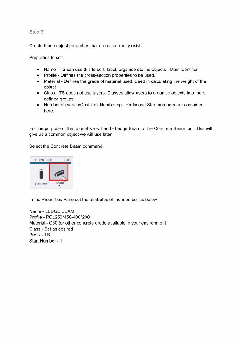
Step 3. Create those object properties that do not currently exist. Properties to set:
● Name - TS can use this to sort, label, organise etc the objects - Main identifier ● Profile - Defines the cross-section properties to be used. ● Material - Defines the grade of material used. Used in calculating the weight of the
object ● Class - TS does not use layers. Classes allow users to organise objects into more
defined groups ● Numbering series/Cast Unit Numbering - Prefix and Start numbers are contained
here. For the purpose of the tutorial we will add - Ledge Beam to the Concrete Beam tool. This will give us a common object we will use later. Select the Concrete Beam command.
In the Properties Pane set the attributes of the member as below Name - LEDGE BEAM Profile - RCL250*450-400*200 Material - C30 (or other concrete grade available in your environment) Class - Set as desired Prefix - LB Start Number - 1

In the Saved settings field, type Ledge Beam and click the Save button
Continue to create all required settings you have listed in your sheet.
Object Type
Name Part Prefix
Part Start Number
Assembly/Cast Unit
Prefix
Assembly/Cast Unit
Start Number
Filter Drawing Object Setting
Steel Beam
BEAM M 1 SB 1 (used in later
tutorial)
(used in later
tutorial)
Steel Column
COLUMN M 1 C 1
Steel Rafter
RAFTER M 1 R 1
Steel Purlin
PURLIN M 1 PN 1

Step 4. Move all of the saved setting files to the Firm folder. The settings will be found in the attributes folder in the model folder. File - Open model folder.
Concrete Beam
BEAM - - CB 1
Concrete Column
COLUMN - - CC 1
Concrete Pile
PILE - - CP 1
Ledge Beam
LEDGE BEAM

Double click the attributes folder.
Sort the folder by the date modified to bring the file to the top of the Explorer window
You need to ensure that you get all of the files which have been created. When you save object properties there will be at least 2 files created. For Example: Ledge Beam.cbm Ledge Beam.cbm.more

Select all of the required files and CUT them from the attributes folder.
Paste them into the Firm folder /Model_Settings folder we set up previously.

Step 5. Test the files working from the firm folder. Shut down Tekla Structures and restart. Create a New model.
Note: Model name is not important. Select one of the modelling tools which should have one of your saved settings in it.
Check the load dropdown for the filename. Select.

Check the parameters are correct.
Add the object to the model space.