n. 3, marzo 2015 - anno 107 la metallurgia...
TRANSCRIPT

Pos
te Ita
liane
spa
- S
pedi
zion
e in
abb
onam
ento
pos
tale
- D
L 3
53
/20
03
(co
nv. in
L. 2
7/0
2/0
4 n
. 4
6) ar
t. 1
., c
omm
a1 D
CB
UD
.Ann
o 107,
n. 3
- M
arzo
20
15
- Per
iodi
co m
ensi
le
CONSEDIT - Viale Europa Unita, 29 - 34073 Grado (GO) - Tel. 0431 876070 - Fax 0431 886507 - www.consedit.com - [email protected]
La Metallurgia ItalianaOrgano ufficiale dell’Associazione Italiana di Metallurgia.Rivista fondata nel 1909
International Journal of the Italian Association for Metallurgy
N. 3, marzo 2015 - Anno 107

European Conferenceon Heat Treatment 2015&22nd IFHTSE CongressHeat Treatment and Surface EngineeringFrom tradition to innovation
Organised by
Sponsored by
REGISTER NOW!
Associazione Italiana di Metallurgia
Programme
With about 160 papers in the programme, we expect ECHT 2015 & 22 IFTHSE in Venice to be a vibrant and successful event. The 90 oral presentations and over 70 posters will give life to parallel sessions covering:
Invited lecturer
Exhibition & SponsorshipThe Conference will feature a technical exhibition that will represent many areas of industry with latest equip-ment, facilities and instruments, products and services in the field of heat treatment and surface engineering. Companies will be able to reinforce their participation and enhance their corporate identification by taking advantage of benefits offered to them as Contributing Sponsors of the Conference.Companies interested in taking part in the exhi-bition or sponsoring the Conference may contact the ( · tel. +39 02 76021132).
Conference venueThe Conference will be held in Venice, at
(Viale Ancona 2, Venezia Mestre, Venice - Italy).
Conference organisersASSOCIAZIONE ITALIANA DI METALLURGIAp.le Rodolfo Morandi 2 · 20121 Milano · Italyphone: +39 02.7602.1132 or +39 02.7639.7770fax +39 02.7602.0551 · e-mail: [email protected] conference website: www.aimnet.it/ht2015.htm
ScopeThe long-standing co-operation between AIM - Associazione Italiana di Metallurgia - and the IFHTSE - Inter-national Federation for Heat Treatment and Surface Engineering - has already led to the joint organisation of significant events, such as the Congresses held in Florence in 1982 and in 1998 and the Congress on automotive applications organized in Riva del Garda in 2005.Now, our combined resources will be focused on the organization of a Conference that will deal with tradition and innovation in heat treatment and surface engineering. The Conference will join the European Conference on Heat Treatment 2015 and the 22nd IFHTSE Congress.
Conference website: www.aimnet.it/ht2015.htm
VENICE ITALY, 2022 MAY 2015
22_IFHTE_Congress_1Ann_PubbA4.indd 1 12/03/15 09:55

La Metallurgia Italiana
Direttore Responsabile:Gianangelo Camona
Comitato scientifico - Editorial Panel:Livio Battezzati, Riccardo Carli, Mario Conserva, Augusto Di Gianfrancesco, Franco Dinucci, Carla Gambaro, Gian Luca
Garagnani, Bevis Hutchinson, Chong Soo Lee, Alberto Molinari, Roberto Montanari, Elena Pereloma, Giorgio Poli, Emilio
Ramous, Claudia Rinaldi, Roberto Roberti, Hans J. Roven, Dieter Senk, Piotr R. Scheller, Pierre Soulignac, Jean-Marc Steiler, Stefano Trasatti, George F. Vander Voort, Maurizio Vedani
Segreteria di redazione:Antonella Donzelli
Comitato di redazione:Federica Bassani, Gianangelo Camona,
Antonella Donzelli, Ottavio Lecis, Carlo Mapelli
Direzione e redazione:AIM - P.le R. Morandi 2 - 20121 Milano
tel. 02 76 02 11 32 - fax 02 76 02 05 [email protected] - www.aimnet.it
Gestione editoriale, pubblicità e abbonamenti:CONSEDIT sas
Viale Europa Unita, 29 - 34073 Grado (GO)Tel. 0431 87 60 70 - fax 0431 88 65 [email protected] - www.consedit.com
Abbonamento annuale (10 numeri):Italia: 83,00 € - Estero, zona 1 (Europa e bacino Mediterraneo): 124,00 €
Altri Africa/Asia e Americhe: 150,00 €; Oceania: 160,00 €Costo singolo fascicolo (spese di spedizione escluse): 10,00 €
Per sottoscrivere l’abbonamento è sufficiente effettuare un bonifico bancario intestandolo a CONSEDIT sas e utilizzando il seguente codice
IBAN (Credito Cooperativo Friuli):IT 19 I 07085 64590 015210014135
Si prega quindi di darne avviso tramite mail, indicando nome, cognome, azienda, indirizzo e telefono, a:
[email protected]. L’abbonamento decorrerà dal primo numero raggiungibile a pagamento avvenuto.
Garanzia di riservatezza per gli abbonati:Le informazioni custodite nell’archivio elettronico dell’Editore verranno utilizzate ai sensi del D.Lgs. 196/03. L’Editore garantisce la massima
riservatezza dei dati forniti dagli abbonati e la possibilità di richiederne gratuitamente la rettifica o la cancellazione scrivendo a:
CONSEDIT sas - Responsabile DatiViale Europa Unita, 29 - 34073 Grado (GO)
La riproduzione degli articoli e delle illustrazioni è permessa solo citando la fonte e previa autorizzazione della Direzione della rivista.
Reg. Trib. Milano n. 499 del 18/9/1948.Sped. in abb. Post. - D.L.353/2003 (conv. L. 27/02/2004 n. 46)
art. 1, comma 1, DCB UDConsedit sas è iscritta al Roc con il num. 4109
Stampa: Poligrafiche San Marco sas - Cormòns (GO)
Metallurgia fisica
Lega eutettica Pb-Bi allo stato liquido: studio dell’ordine a breve raggioR. Montanari, A. Varone ......................................................3
Schiume metalliche
Mechanical characterization of AISI 316 tubes filled with Al alloy foamsG. Costanza, A. Sili, M.E.Tata ..............................................9
Tribologia
Effetti della diluizione sulla microstruttura e omportamento ad usura di una lega Fe-C-B-Cr-ML. Rovatti, J. N. Lemke, M. Colombo, O. Stejskal, M. Vedani ..15
Metallurgia delle polveri
Shot peening of a sintered Ni-Cu-Mo steel produced by diffusion bonded powdersL. Emanuelli, M. Biesuz, S. Libardi, P. Marconi, A. Molinari ... 23
Acciaio
Disegno metallurgico di una microstruttura alto resistenziale ad alta tenacità e deformabilità migliorataA. Di Schino, G. Porcu, C. Zhang, Z. Lei ..........................29
Saldatura
Influenza dei parametri di saldatura sulla microstruttura di giunti saldati SMAw/GTAw di acciaio X 10 CrMoVNb9-1 (P91)G. Barbieri, M. Cesaroni, L. Ciambella, G. Costanza, R. Montanari ....................................................................37
Trattamenti superficiali
ZnO nanowires grown on bulk ZnO coatings: mechanical response to deep cryogenic treatmentM. Cabibbo ......................................................................47
The effect of deep cryogenic treatment on hardness and wear behavior of the H13 tool steelK. Amini, M. Negahbani, H. Ghayour .................................53
International Journal of the Italian Association for Metallurgy
Mensile dell’Associazione Italiana di Metallurgia fondata nel 1946
Pos
te Ita
liane
spa
- S
pedi
zion
e in
abb
onam
ento
pos
tale
- D
L 3
53
/20
03
(co
nv.
in L
. 2
7/0
2/0
4 n
. 4
6)
art.
1.,
com
ma1
DC
B U
D.
Ann
o 1
07
, n.
3 -
Mar
zo 2
01
5 -
Per
iodi
co m
ensi
le
CONSEDIT - Viale Europa Unita, 29 - 34073 Grado (GO) - Tel. 0431 876070 - Fax 0431 886507 - www.consedit.com - [email protected]
Organo ufficiale dell’Associazione Italiana di Metallurgia.Rivista fondata nel 1909
N. 3, marzo 2015 - Anno 107
N. 3/Marzo 2015
Anno 107 - ISSN 0026-0843

La Metallurgia Italiana - n. 3/20152
Qualche buona ragione per farlo:
✔ L’AIM è un luogo di incontro privilegiato per la diffusione della conoscenza, elemento fonda-mentale per il progresso industriale e scientifi-co della nostra società.
✔ Il tuo sostegno e la tua competenza sono indi-spensabili per l’attività dell’Associazione, che da oltre sessant’anni si impegna attivamen-te nella diffusione della cultura metallurgica, attraverso l’organizazzione di manifestazioni nazionali ed internazionali che toccano tutti gli aspetti della metallurgia.
✔ Nei diversi Centri di Studio, operativi nell’AIM, si realizzano le migliori condizioni per promuo-vere il tuo incontro diretto con gli specialisti delle varie discipline metallurgiche, in campo nazionale.
✔ Nei Centri di Studio, e nelle attività da loro promosse, si concretizza il mix delle migliori esperienze del mondo industriale e del mondo accademico.
✔ La consolidata presenza dell’AIM nel circuito dei convegni internazionali ti permette di rice-vere frequentemente in Italia un aggiornamen-to sulle principali linee di sviluppo della metal-lurgia in campo mondiale.
✔ La qualità di Socio ti consente di godere delle riduzioni nelle quote di iscrizione alle manife-stazioni (fino ad arrivare all’iscrizione gratuita alle Giornate di Studio - per i soci Seniores - e a tutte le manifestazioni organizzate dall’AIM - per i soci Juniores).
✔ L’iscrizione all’Associazione ti garantisce l’abbo-namento gratuito alla rivista mensile La Metal-lurgia Italiana e l’accesso in condizioni favorevo-li ad un’ampia collana tecnica.
Come farlo:
✔ Per diventare socio basta iscriversi online sul sito www.aimnet.it oppure richiedere alla Se-greteria AIM la scheda di iscrizione (Modello A/2014) e restituirla compilata a mezzo e-mail ([email protected]) o fax (02 7602 0551), accompagnata dal versamento della quota as-sociativa.
Associazione Italiana di MetallurgiaPiazzale R. Morandi, 2 – 20121 MilanoTel. 02-76021132 – 02-76397770Fax. 02-76020551E-mail: [email protected] – www.aimnet.it
VUOI DIVENTARE SOCIO AIM?VUOI RINNOVARE L’ASSOCIAZIONE?
HONEGGER GASPARE S.r.l.Via F. Carlini, 1 _ 20146 Milano
Tel. +39 (02)47 79 141Fax +39 (02)48 95 37 [email protected]
www.honegger.it
www.metec.comwww.tbwom.com
worldwide
Battete il ferro fi nché è caldoLa 9. edizione della fi era con congresso dedicata alla metallurgia, all’acciaio fuso e alla produzione di acciaio con congresso trasforma le visioni in impianti e prodotti.
Il motore di crescita: la metallurgiaMETEC con il suo ampio programma collaterale, è l’evento top quando si tratta di macchinari, impianti e prodotti per la produzione di ferro grezzo, acciaio e metallo non ferroso.
Benvenuti a Düsseldorf!
met1502_80x247_IT.indd 1 28.01.15 11:46

La Metallurgia Italiana - n. 3/2015 3
Metallurgia fisica
Lega eutettica Pb-Bi allo stato liquido: studio dell’ordine a breve raggio
R. Montanari, A. Varone
R. Montanari, A. VaroneDipartimento di Ingegneria Industriale,
Università di Roma-Tor Vergata,Via del Politecnico 1, 00133 Roma, Italia
La conoscenza delle modifiche strutturali che avvengono nella lega eutettica Pb-Bi (LBE) allo stato liquido è importante sia da un punto di vista scientifico che applicativo. Questa lega è stata selezionata come liquido di raffreddamento e come sorgente di neutroni di spallazione nello sviluppo di MYRRHA (ADS), quindi le sue
proprietà termo-fisiche giocano un ruolo molto importante.Esperimenti di Spettroscopia Meccanica [1-2] evidenziano nella lega allo stato liquido la presenza di un ampio massimo di frizione interna e una grossa variazione del modulo elastico tra 350 °C e 520 °C. Dopo fusione il
modulo elastico della lega decresce in maniera costante fino a ~350 °C, poi a 400 °C si registra un brusco calo che copre un intervallo di temperatura di circa 170 °C, infine, sopra 520 °C il modulo continua a decrescere con
una pendenza molto simile a quella iniziale.Lo scopo di questo lavoro è stato quello di investigare mediante diffrazione X ad alta temperatura (HT-XRD)
la struttura della lega LBE e la sua evoluzione in un esteso intervallo di temperatura (fino a 720 °C). I risultati mostrano che l’ordine a breve raggio della lega subito dopo fusione corrisponde a una struttura cubo-ottaedrica
che progressivamente evolve verso una struttura icosaedrica al crescere della temperatura. Tale trasformazione si completa intorno a 720 °C.
Keywords: Lega Pb-Bi eutettica - LBE - Metallo liquido - Diffrazione dei raggi X ad alta temperatura -RDF - Trasformazione strutturale
INTRODUZIONE
La lega LBE è stata selezionata come liquido raffreddante e sorgente di neutroni per lo sviluppo di MYRRHA (ADS) [3]. Questo nuovo tipo di reattore può essere considerato una delle possibili soluzioni ai problemi legati alla produ-zione di rifiuti nucleari in quanto è in grado di trasmutare le scorie con alta radioattività e lunghi tempi di dimezza-mento [4].
Possibili cambiamenti strutturali del liquido raffreddante possono influenzare l’interazione di quest’ultimo con i ma-teriali strutturali. Per tali ragioni in studi precedenti [2] la lega LBE è stata analizzata mediante frizione interna (IF) e misure di modulo elastico dinamico a temperature molto maggiori di quella di fusione (125 °C) usando un nuovo metodo da noi sviluppato. Dopo la fusione della lega, gli andamenti di Q-1 e E/E0 (il modulo elastico E è normalizza-to al valore iniziale E0) in funzione della temperatura sono
caratterizzati da una marcata caduta del modulo elastico che inizia a 350°C. La variazione copre un intervallo di circa 170 °C, mentre sopra i 520 °C il modulo continua a decrescere con una pendenza molto simile a quella ini-ziale. In corrispondenza di tale caduta sono stati registrati dei massimi di frizione interna. Zu et al.[1] effettuando con il pendolo torsionale degli esperimenti simili sulla stessa lega hanno osservato un massimo di Q-1 intorno a 550 °C. Risultati analoghi sono stati ottenuti anche in leghe Pb-Bi con diversa composizione da quella eutettica oltre che in altre leghe binarie [5-7]. In tali studi si è assunto che la struttura della lega fosse eterogenea dopo la fusione, con la presenza di un numero, seppur ridotto, di cluster cristallini che ad alta temperatura tendono a disgregarsi determinando una struttura più uniforme.
Questi risultati sono in accordo con anomalie della con-duttività elettrica s(T) osservate da Plevachuk et al. [8] e Li et al. [9], i quali attribuirono queste deviazioni dalla line-arità a una disomogeneità strutturale del metallo liquido.
Brazhkin et al. [10] osservarono la presenza di una tra-sformazione del primo ordine dipendente dalla pressione in alcuni metalli liquidi quali: Se, S, Bi, Sn, Sb, Te, e I che è stata attribuita ad un cambio nell’ordine a breve raggio del liquido. Transizioni simili sono state studiate anche nel P

La Metallurgia Italiana - n. 3/20154
Memorie
e N [11-12]. Anche in alcune leghe binarie quali Sn, Pb-Bi, Pb-Sn, In-Bi [1-2,13-14] sono stati registrati dei cambia-menti nella struttura del liquido a temperature molto supe-riori a quella di liquidus, ovvero in una zona del diagramma di stato dove non sono presenti curve. Per comprendere meglio l’evoluzione strutturale che la lega eutettica Pb-Bi subisce all’aumentare della tempera-tura sono state effettuate misure di diffrazione X ad alta temperatura (HT-XRD) fino a 720 °C e dagli spettri di dif-frazione è stata determinata la funzione di distribuzione radiale (RDF) che fornisce informazioni sull’ordine a breve raggio presente nel metallo liquido. E’ stato anche realiz-zato un modello per descrivere la ri-organizzazione degli atomi e la sua evoluzione in funzione della temperatura.Infine, la RDF è stata interpolata con le funzioni di coppia per determinare la distanza delle coppie atomiche Pb-Pb, Bi-Bi e Pb-Bi nel fuso fino a 720 °C.
MAteRiALi e Metodi
Il materiale esaminato è la lega Pb-Bi con composizione eutettica (Pb 44.1-Bi 55.9 % at).
Le misure HT-XRD sono state effettuate mediante l’impie-go di una camera ANTON PAAR HT-16 con un porta-cam-pione adatto a contenere il metallo liquido in atmosfera di gas inerte. Gli spettri di diffrazione sono stati registrati utilizzando la radiazione Mo-Kα (λ = 0.7093 Å) e incre-mentando la temperatura per monitorare possibili cam-biamenti strutturali che avvengono nel metallo liquido. Durante ciascun test la temperatura, controllata median-te una termocoppia posta direttamente in contatto con il campione, è stata mantenuta costante (± 0.1 K). Gli spettri XRD sono stati misurati nell’intervallo angolare 2Q 5-55° con passo di 0.05° e tempo di conteggio di 5 s per passo. Prima di ciascun test la temperatura è stata mantenuta costante per circa 30 minuti in modo che il campione po-tesse raggiungere la corretta stabilità termica. Dallo spet-tro di diffrazione del metallo liquido è stata determinata la funzione RDF, 4pr2r(r). Essa fornisce informazioni sul numero di atomi posti a una distanza compresa tra r e r+dr dal centro di un dato atomo.
AnALisi degLi sPettRi xRd
In un liquido poli-atomico come nel caso della lega LBE si può scegliere una conveniente unità di composizione, designata con UC, come unità di struttura. In questo modo il liquido risulta completamente costituito da tali unità. In generale per una lega binaria del tipo AXB1-X si possono usare come unità di composizione X atomi di A e 1-X atomi di B. Nel caso presentato avremo quindi X = 44.1 % e 1-X = 55.9 % .Il fattore di scattering medio per elettrone fe è dato dalla seguente relazione [15]:
(1)
dove Zm e fm sono rispettivamente il numero atomico e il fattore di scattering atomico degli atomi di tipo m. La somma UC è estesa a tutti gli atomi nell’unità di composizione. Il fattore di scattering vale fm = Km fe dove m = 1 per il Pb e m = 2 per il Bi (Z1 = 82 e Z2 = 83).L’intensità di diffrazione X, I(Q), viene usualmente espressa in termini di Q=4psinθ/λ dove θ è l’angolo di diffrazione e λ è la lunghezza d’onda. La curva sperimentale è preliminarmente corretta dagli effetti dovuti all’assorbimento A e alla polarizzazione P per ottenere l’intensità I*(Q) che poi sarà convertita in unità assolute Ieu*(Q). Ulteriori dettagli sulla procedura sono riportati in [16].La funzione i(Q) può essere quindi espressa in termini di Ieu*(Q):
(2) dove I*eu(Q)/N è l’intensità in unità elettroniche per atomo e 1/g2(Q) è un fattore di convergenza. La funzione g(Q) = 1 quando Q = 0. La RDF è stata calcolata utilizzando la seguente relazione:
(3) dove re è la densità elettronica media nel campione.La curva RDF differenziale G(r) può essere ottenuta sottraendo il contributo parabolico ∑UC je Zr rp 22 alla RDF. Le posizioni r1 e r2 del primo e del secondo massimo della RDF possono essere determinate con estrema precisione e rappresentano il raggio medio del primo e del secondo guscio atomico attorno ad un atomo che viene preso come riferimento. Dal rapporto r2 / r1 è possibile ottenere indicazioni sull’arrangiamento atomico nel liquido. Siccome i raggi atomici del Pb e del Bi sono molto simili (raggio atomico: Pb = 0.175 nm , Bi = 0.143 nm) i picchi della RDF sono la sovrapposizione del contributo delle coppie Pb-Pb, Bi-Bi e Pb-Bi. Introducendo le funzioni di coppia Pij:
(4) la RDF può essere quindi espressa come segue:
5)
Combinando l’Eq. (3) e l’ Eq. (5) si ottiene la seguente espressione:
(6)
Le funzioni di coppia Pij(r) sono state determinate mediante l’ Eq. (5) introducendo per le coppie Pb-Pb e Bi-Bi i valori di rij determinati per i metalli puri. Le distanze delle coppie Pb-Bi e i valori di Nij sono stati adattati nel termine a sinistra dell’ Eq. (6) in modo da ottenere la

La Metallurgia Italiana - n. 3/2015 5
Metallurgia fisica
migliore interpolazione del termine a destra. Il metodo è stato utilizzato per analizzare gli spettri di diffrazione della lega allo stato liquido alle diverse temperature.
RisuLtAti e discussione
In Fig. 1 sono riportate le funzioni G(r) per alcune temperature selezionate. Per descrivere la struttura del liquido la distanza media r1 tra atomi primi vicini è di particolare rilevanza, essa corrisponde alla posizione centrale del primo massimo della RDF. Come risulta particolarmente evidente dalla Fig. 2 il valore di r1 in funzione della temperatura decresce in maniera netta appena si raggiunge la temperatura di 350°C. A temperature superiori a 520°C r1 non subisce più sostanziali variazioni. È possibile notare che la brusca variazione di r1 ha luogo in corrispondenza dello stesso intervallo di temperatura dove è stata osservata la caduta del modulo elastico [2]. Dall’ analisi degli andamenti delle RDF in funzione della temperatura è stato inoltre possibile osservare che il primo massimo si muove verso angoli più alti mentre il secondo in direzione opposta. Questo spostamento indica un ri-arrangiamento atomico che può essere descritto mediante il rapporto r2/r1 come mostrato in Fig. 3. Il rapporto r2/r1 passa da un valore di ~1.41 subito dopo la fusione a ~1.61 quando la temperatura raggiunge 720 °C. Per comprendere tali risultati è utile considerare alcuni studi fatti da Reichert et al. [17]. Questi ricercatori furono i primi ad osservare sperimentalmente una simmetria a base cinque nel Pb liquido catturando frammenti di liquido su Si monocristallino (111) e misurando la radiazione X evanescente che risulta estremamente sensibile all’interfaccia solido-liquido. Questa è stata la prima evidenza sperimentale dell’esistenza in un liquido mono-atomico, di un impacchettamento di tipo icosaedrico come era stato già ipotizzato da Frank [18] e Bernal [19]. Se si considera che in un liquido gli atomi interagiscano mediante un potenziale simmetrico come quello di Lennard-Jones, l’arrangiamento locale che gli atomi tenderanno ad avere sarà un impacchettamento poliedrico di icosaedri formati da 13 atomi. Questo tipo di configurazione richiede infatti 8.4 % di energia in meno rispetto a una configurazione di cluster con alto impacchettamento di tipo cristallino. La principale caratteristica di una simmetria a base cinque come quella che si ha in un icosaedro è che essa non è in grado di ricoprire l’intero spazio e quindi non consente di formare un cristallo. Un impacchettamento di questo tipo può essere quindi visto come un tentativo di massimizzare la densità a breve raggio. La più densa configurazione che può essere creata utilizzando delle sfere rigide è quella di un tetraedro e unendo 12 tetraedri tra loro attorno a un vertice comune è possibile formare un icosaedro come quello mostrato in Fig. 4 (a). Nella struttura icosaedrica il rapporto r2 / r1 ovvero tra la distanza di atomi secondi e primi vicini è pari al numero aureo f = 1.618.
Fig. 1 - Curve G(r) ottenute a diverse temperature
Fig. 1 - G(r) curves at different temperatures
Fig. 2 - Distanza media r1 degli atomi primi vicini in funzione della temperatura
Fig. 2 - Average distance r1 of 1st nearest neighbour atoms determined at different temperatures
Fig. 3 - Rapporto r2/r1 in funzione della temperatura
Fig. 3 - Trend of the ratio r2/r1 vs temperature
G(r
)

La Metallurgia Italiana - n. 3/20156
Memorie
Subito dopo la fusione (125°C) il rapporto r2 / r1 della lega LBE risulta essere pari a 1.41, un valore molto vicino a 2dunque l’arrangiamento elementare degli atomi nel Pb-Bi allo stato liquido corrisponde piuttosto a una configurazione costituita da cuboottaedri, come quello mostrato in Fig. 4 (b), piuttosto che a un icosaedro. Con l’aumentare della temperatura il rapporto r2/r1 (Fig. 3) subisce un incremento progressivo fino a 720°C, temperatura alla quale diventa pari a ~1.61, valore estremamente vicino al numero aureo f. Questo risultato indica sostanzialmente che l’ordine a breve raggio della lega eutettica si modifica seguendo un’evoluzione strutturale che porta il liquido da una configurazione di tipo cubo-ottaedrica a bassa temperatura, appena dopo la fusione, a una configurazione di tipo icosaedrica a 720 °C.Siccome la RDF rappresenta il numero medio di atomi posti a una distanza compresa tra r e r + dr dal centro di un dato atomo preso come riferimento, essa rappresenta la struttura media del liquido ma non fornisce ulteriori dettagli legati alle specifiche strutture che possono temporaneamente esistere in una zona o in un’altra. Di fatto è una media nel tempo e nello spazio quindi un certo rapporto r2/r1 non permette di sapere se esiste un’unica configurazione in tutto il fuso oppure se coesistono più strutture di cui il rapporto in questione è la media. In altre parole l’arrangiamento atomico nella lega liquida ad una temperatura qualsiasi tra 125 °C e 720 °C potrebbe essere costituito dalla coesistenza di cluster cubo-ottaedrici e icosaedrici con quantità relative che variano in funzione della temperatura stessa.
Fig. 4 - Struttura icosaedrica (a) e cubo-ottaedrica (b).
Nelle figure sono mostrati gli atomi primi e secondi vicini
ad un atomo preso come riferimento (O)
Fig. 4 - Icosahedral (a) and cuboctahedral (b) structure.
Figures show the first and the second neighbour atoms of a
given atom (O).
Fig. 5 - Il modellino mostra le strutture cubo-ottaedrica
(a) e icosaedrica (b)
Fig. 5 - Model shows the two structures: cuboctahedral (a)
and icosahedral (b)
Ipotizzando che il rapporto r2/r1 dipenda da una singola configurazione in tutto il fuso si è cercato di descrivere la trasformazione che porta da un cubo-ottaedro ad un icosaedro. Per comprendere bene come sia possibile il passaggio da una configurazione all’altra è stato anche realizzato un modello fisico in legno (Fig. 5). Sia l’icosaedro che il cubo-ottaedro sono poliedri che possono essere costruiti a partire da un ottaedro, un solido con 12 spigoli di lunghezza a. Se gli atomi occupano le posizioni centrali di ciascun spigolo dell’ottaedro (coordinata 0.5 a) costituiscono i vertici di un cubo-ottaedro (Fig. 5 a), se invece occupano le posizioni ottenute dividendo ciascun spigolo per il numero aureo (1/1.618) a = 0.61 a formano i vertici di un icosaedro (Fig. 5 b). Però per ogni spigolo ci sono due posizioni 0.61 a quindi nella trasformazione da cubo-ottaedro a icosaedro gli atomi si devono spostare tutti in modo coordinato. In particolare, facendo riferimento a ciascuna faccia triangolare dell’ottaedro si debbono spostare o tutti in senso orario o tutti in senso antiorario. Ovviamente le posizioni intermedie tra 0.5 a e 0.61 a possono rappresentare le configurazioni presenti nel liquido a temperature tra 125 °C e 700 °C.L’evoluzione strutturale osservata è pertanto associabile a cambiamenti strutturali in cui gli atomi del metallo liquido disposti inizialmente in una configurazione cubo-ottaedrica si riorganizzano in una configurazione icosaedrica. L’andamento mostrato in Fig. 3 non è continuo ma mostra un plateau tra 350 e 520 °C, nello stesso intervallo in cui sono stati registrati la variazione di modulo elastico e i massimi di frizione interna [2].
a) b)
a) b)

La Metallurgia Italiana - n. 3/2015 7
Metallurgia fisica
Alla luce di questi risultati si è pensato di effettuare un’ulteriore analisi sugli andamenti delle RDF. In particolare si è voluto osservare come varia il contributo delle varie funzioni di coppia Pb-Pb, Bi-Bi e Pb-Bi per ciascun massimo della RDF in funzione delle diverse T. I picchi della RDF sono in realtà la somma del contributo delle coppie Pb-Pb, Bi-Bi e Pb-Bi in quanto per tale lega la loro posizione centrale è molto vicina ed è quindi impossibile distinguere i diversi contributi. Per tale ragione sono state effettuate delle interpolazioni mediante le funzioni di coppia Pij(r). In Fig. 6, a titolo di esempio, si mostra l’interpolazione del primo massimo della RDF a 126 °C. Come è possibile osservare la RDF viene correttamente interpolata dalle funzioni P11 (Pb-Pb) e P22 (Bi-Bi) senza dover considerare il contributo delle coppie miste Pb-Bi. Le stesse analisi sono state effettuate anche sulle RDF ottenute ad altre temperature fino a 720 °C. In tabella sono riportate le posizioni centrali delle funzioni di coppia P11 (Pb-Pb), P22 (Bi-Bi) e P12 (Pb-Bi) così ottenute. Fino a 350 °C la coppia mista Pb-Bi non è presente indicando che nonostante l’avvenuta fusione della lega allo stato liquido vi è ancora la presenza di numerosi cluster provenienti dal solido originale. Mentre incrementando la temperatura la struttura del metallo liquido tende a uniformarsi (comparsa delle coppie miste) diventando un liquido progressivamente più omogeneo.
concLusioni
Alla luce dei risultati ottenuti è possibile concludere che allo stato liquido la lega LBE subisce un’evoluzione strutturale che viene descritta dal rapporto r2/r1 (Fig. 3) in funzione della temperatura. Gli atomi subito dopo la fusione hanno un ordine a breve
raggio consistente con una configurazione di tipo cubo-ottaedrica (r2/r1=1.41). All’aumentare della temperatura il rapporto r2/r1 cresce fino a raggiungere a 720 °C il valore 1.61 indicativo di una configurazione di tipo icosaedrico. La trasformazione geometrica cubo-ottaedro —› icosaedro è stata descritta e verificata utilizzando un piccolo modello fisico da noi realizzato.L’interpolazione delle curve RDF con le funzioni di coppia mostra che nella lega non sono presenti coppie miste Pb-Bi dalla fusione (125 °C) fino a 350 °C. Sopra questa temperatura si formano coppie miste Pb-Bi e la lega diventa più omogenea.
RingRAziAMenti
Gli autori ringraziano i Sigg. Benedetto Iacovone e Piero Plini del Dipartimento di Ingegneria Industriale dell’ Università di Roma-Tor Vergata per la preparazione dei provini.
BiBLiogRAfiA
1] F. Q. ZU, Z.G. ZHU, B. ZHANG, Y. FENG, J.P. SHUI, J. Phys. Condens. Matter, 13 (2001) p. 11435.
2] R. MONTANARI, A. VARONE, Solid State Phenomena, 184 (2012) p. 434.
3] L. CINOTTI, B. GIRAUD, H.A. ABDERRAHIM, J. Nucl. Mater. 335 (2004) p. 148.
4] I.S. HwANG, S.H. JEONG, B.G. PARK, w.S. YANG, K.Y. SUH, C.H. KIM, Prog. Nucl. Energy 37 (2000) p. 217.
5] F. Q. ZU, Z. G. ZHU, L. J. GUO, X. B. QIN, H. YANG, w. J. SHAN, Phys. Rev. Lett., 89–12 (2002) p. 125505.
6] F. Q. ZU, X. F. LI, L. J. GUO, H. YANG, X. B. QIN, Z. G.
Fig. 6 - (a) Analisi del 1° massimo della RDF ottenuta 125 °C. (b) La tabella mostra le distanze rij delle coppie Pb-Pb, Bi-Bi e Pb-Bi determinate ad alcune temperature più significative.
Fig. 6 - (a) Fitting of the first RDF maximum at 125°C. (b) Table shows the distance rij between Pb-Pb, Bi-Bi and Pb-Bi pairs for some temperatures

La Metallurgia Italiana - n. 3/20158
Memorie
ZHU, Physics Lett. A, 324 (2004) p. 472.7] F. Q. ZU, L. J. GUO, Z. G. ZHU, Y. FENG, Chin. Phys.
Lett., 19 (2002) p. 94.8] Yu. PLEVACHUK, V. SKLYARCHUK, S. ECKERT, G.
GERBETH, J. Nucl. Mater. 373 (2008) p. 335.9] Q. LI, F.Q. ZU, X.F. LI, Y. XI, Mod. Phys. Lett. B, 20/4
(2006) p. 151.10] V.V. BRAZHKIN, S.V. POPOVA, R.N. VOLOSHIN, High
Pressure Research, 15 (1997) p. 267.11] Y. KATAYAMA, J. Non-Cryst. Solids, 312-314 (2002) p. 8.12] G.D. MUKHERJEE, R. BUEHLER, Phys. Rev. Lett., 99
(2007) p. 225701.
13] Z.G. ZHU, F.Q. ZU, L.J. GUO, B. ZHANG, Mater. Sci. Eng. A, 370 (2004) p. 427.
14] I. KABAN, w. HOYER, YU PLEVACHUK, V. SKLYARCHUK, J. Phys. Condens. Matter, 16 (2004) p. 6335.
15] B.E. wARREN, H. KRUTTER, O. MORNINGSTAR, J. Amer. Ceram. Soc., 19 (1936).
16] R. MONTANARI, Int. J. of Mater. and Prod. Techn., 20 (2004) p. 452.
17] H. REICHERT, O. KLEIN, H. DOSCH, M. DENK, V. HONKIMAKI, T. LIPPMANN, G. REITER, Nature, 408 (2000) p. 839.
18] F.C. FRANK, Proc. Roy. Soc. London A, 215 (1952) p. 43.19] J.D. BERNAL, Nature 185 (1960) p. 68.
Liquid Pb-Bi eutectic alloy:study of short-range order
Keywords: Pb-Bi eutectic alloy - LBE - Liquid metal - High-temperature X-ray diffraction -RDF - Structural transformation
Liquid Pb–Bi eutectic (LBE) alloy has been selected as a coolant and neutron spallation source for the development of MYRRHA, an accelerator driven system (ADS). This new reactor type might be one of the possible solutions for the nuclear waste problem because it is able to transmute high level radioactive waste and long lived actinides. The ADS technology however requires special operating conditions. The materials need to resist temperatures ranging between 200-550°C under a high energy neutron flux and in contact with the LBE. This condition increases liquid metal corrosion and embrittlement, in fact the limitation of ADS life is due to the relatively low corrosion resistance of structural materials in the LBE environment. The compatibility of structural materials with liquid LBE at high temperature is one of the key issues for the commercialization of such fast reactors. Possible structural changes of the liquid may affect the interaction of LBE with structural materials. Therefore, in previous works LBE was investigated by internal friction (IF) and dynamic modulus measurements far above the eutectic temperature (125 °C) by using a new method developed by us. After melting the alloy exhibits a steady modulus decrease up to 350 °C, here a remarkable drop is observed covering a temperature range of about 170 °C. Finally, above 520°C, modulus continues to decrease with slope very close to the initial one. In correspondence of the modulus drop two IF maxima were detected: the first centered at ~350 °C, the second at ~460 °C. Anomalies of the liquid metal have been evidenced by other investigators as well. It is believed that the structure of the alloys is heterogeneous after melting, with residual minor crystals still existing and, when the critical temperature is reached, the residual conglomerates are broken and the uniform structure appears.To better understand the nature of LBE structural evolution vs. temperature High Temperature X-Ray Diffraction (HT-XRD) measurements have been carried out up to 720 °C; from diffraction patterns the radial distribution function (RDF) has been calculated (some G(r) curves are reported in Fig. 1). RDF provides information about possible changes of liquid metal. The average distance r1 between the 1st nearest neighbour atoms is of particular relevance: the position (Fig. 2) and shape of 1st RDF peak progressively change as temperature increases with strict correspondence with the dynamic modulus drop previously observed by us. The trend of the ratio r2 / r1 vs. temperature (Fig. 3) showed that just after melting r2 / r1 is ~ 1.41, increases till to reach the value of ~1.61 at 720 °C. The result indicates that the short-order of liquid LBE gradually changes from a cuboctahedral configuration (the ratio is 2 ) just after melting to an icosahedral one (the ratio corresponds to the golden ratio f = 1.618 ) at 720 °C. The two structures of the liquid are shown in Fig. 4.To describe structural re-arrangement of atoms in the liquid from cuboctahedral to icosehedral configuration a model has been realized (Fig. 5). The fitting of the first RDF peak by pair functions Pij(r) permitted to identify and determine the single contributions at increasing temperature. From melting up to 350 °C, the mixed Pb–Bi pairs are not present. They appear at 350 °C and their contribution to RDF 1st peak becomes more important as temperature increases. In fact, the increasing number of Pb-Bi pairs corresponds to a more homogeneous elemental distribution in the alloy.

La Metallurgia Italiana - n. 3/2015 9
Schiume metalliche
Mechanical characterization of Aisi 316 tubes filled with Al alloy foams
g. costanza, A. sili, M.e.tata
g. costanza, M.e.tataDipartimento di Ingegneria Industriale, Università di
Roma - Tor Vergata
A. siliDipartimento di Ingegneria Elettronica, Chimica e
Ingegneria Industriale, Università di Messina
In tubular elements filled with metal foams the structural collapse is delayed in comparison with the empty tubes, consequently compression strength and absorbed energy increase. Production methods of foams are crucial, as they determine cellular morphology and bonds formation with tube wall. In this work AISI 316 steel tubes filled
with foam of commercially pure Al and Al-Si alloys with hypoeutectic compositions were produced. The process parameters were optimized to obtain closed cells foams with an acceptable morphology of porosity and good
mechanical properties. Foams were characterized by optical and scanning electron microscopy and by computer tomography; mechanical properties were investigated by axial compression tests (performed on foam samples and on Cu tubes, empty or filled with foams) and radial compression “Brazilian test” (carried out on AISI 316
tubes, empty or filled with foams).
Keywords: Aluminum foams - Metallography - Mechanical Testing - Non-destructive testing - Processes
intRoduction
In the automotive industry particular attention has been oriented to the utilization of structural elements as energy absorbers, in order to guarantee good passenger protection by transforming, in the event of collision, kinetic energy in deformation energy [1]. Cellular materials, as metal foams, light and high energy absorber, are very attractive in au-tomotive applications where crashworthiness, fuel saving and CO2 emission restraint are critical parameters [2].In recent years, aluminum foams have been widely used thanks to their low density and melting point which facili-tate production process [3]. Their porous structure allows to absorb significant amounts of energy at constant and relatively low stress; in particular compression behavior is affected by cells morphology, as quoted in literature through experimental surveys [4,5] and numerical simu-lation [6]. Strain rate is critical for compression behavior of foams [7]: in quasi-static conditions, the compression diagram of a closed-cell Al foam is characterized by a short initial elastic phase, a broad plateau of plastic deformation (up to strain around 50-60%), with the gradual disappea-
rance of cells of greater diameter, and a final stage with a sudden load increase due to cells collapse in the whole sample [8]. Compression properties, such as elastic modu-lus, plastic plateau wideness and related absorbed energy depends on the collapse mode of cells [9, 10], which are affected by production process parameters [11]. In this field computer tomography has been experimented as a useful tool for observing, step by step, compression of a single sample [8].Metallic tubes filled with Al foam cores are attractive because of the interaction between tube wall and foam which delays the structural collapse and increases ener-gy absorption during compression or bending [12]. The efforts of many researchers have been directed towards the optimization of foaming conditions inside tubes [13], testing the effects of such filling on impact energy absorp-tion in structural components [14], developing numerical simulation in order to study the buckling patterns [15] and carrying out size optimization of a hollow tube acting as energy absorber, evaluating also the effects of filling [16]. During deformation of a tube filled with metal foam, the collapse mode of cells and their interaction with the con-tainer inner surface play an important role. As regards the production process, it is necessary to avoid the formation of an insulating oxide film between foam and tube internal surface: the possibility of obtaining the formation of me-tallurgical bonds through foaming in situ with appropriate precautions was experimented in [17]. A careful investiga-tion of metal foams and filled tubular elements requires the preparation of numerous specimens at different com-pression levels, in order to perform a 3D reconstruction

La Metallurgia Italiana - n. 3/201510
Memorie
during deformation of both cells structure [18] and the whole foam/tube system [19].In a previous work [19], copper tubes filled with alumi-num foam were produced through a foaming compacted powders inside them: the axial compression behavior of these elements was studied by means of tomographic ob-servations carried out at various levels of compression.In this work AISI 316 steel tubes filled with foam of com-mercially pure Al and Al-Si hypoeutectic alloy are produced too. The first goal has been the process parameters opti-mization to obtain closed cells foams with an acceptable morphology of porosity and good mechanical properties, successively manufacturing filled tubes to be utilized as energy absorber. Foams were metallographically charac-terized by optical and scanning electron microscopy (SEM) and by computer tomography (CT); mechanical proper-ties were investigated by axial compression test on foams samples and copper tubes (empty or filled) and radial compression “Brazilian test” on AISI 316 tubes (empty or filled).
MAteRiALs And MetHods
Foams production
Foams production was performed by compacted powders method [20]. On the basis of the process parameters de-veloped in previous work [21 - 24], foams with closed cells of AlSi hypoeutectic alloys were produced. Silicon lowers the melting point of aluminum making it closer to that of the foaming agent decomposition (465°C). Such alloying gives a remarkable increase of hardness than pure alumi-num, improving wear resistance and mechanical proper-ties in general; however, an excess of Si gives excessive fluidity making difficult to control bubbles growth; moreo-ver Si can significantly embrittle the cells walls carrying to collapse during deformation.Commercially pure Al powder (96.6%), alone or with Al-Si12 alloy powder to obtain hypoeutectic compositions (both 44 μm average diameter), was suitable mixed with TiH2 powder as foaming agent (5 μm average diameter) and SiC powder (37 μm average diameter) to increase vi-scosity and stabilize porosity by acting on the interface metal - bubble.The following compositions were considered: TiH2 (0.4 - 0.6 weight %), SiC (3 - 9 weight %) and metals powder (commercially pure Al, alone or together with AlSi12) to balance. These powders were carefully mixed to have a homogeneous precursor, because, especially for TiH2 par-ticles, it is a fundamental requirement for producing foams of good quality [25].In order to obtain precursors with diameter of 15 mm and height of 10 mm, powder mixtures were compacted in a mold, by means of hydraulic press, choosing the optimum load for crushing any oxide inside powders (120 kN for commercially pure Al and 150 kN for Al-Si alloys, as a con-sequence of their greater mechanical strength). The oxide layer was removed from the precursor surface by mecha-nical abrasion, to avoid any obstacle to bubble growth du-
ring foaming. Precursors were placed inside Cu tubes or AISI 316 steel tubes: both tubes were 16 mm diameter and 1 mm thickness and were utilized as crucibles inside a fur-nace at 700°C (optimal temperature for a continuous H2 release) for 5 min (in the case of Cu tubes) or 8 min (AISI 316 tubes). Then samples were extracted from the furnace and water cooled. These combinations of process tempe-rature and time were experimented as suitable for a good compromise between melt viscosity and foam growth.
Metallographic and tomographic investigations
Samples of foams and tube sections, after appropriate me-tallographic preparation and etching with HF (0.5%), were observed by optical microscopy and SEM. Moreover, CT investigations were performed by a variable focus appara-tus (Cu filament and X-ray accelerating voltage of 225 kV), operating in the field of micro-macro focus with spatial re-solution up to 30 microns. The 2D images of tube sections were elaborated to increase contrast and brightness in or-der to highlight cells structure and foam - wall interfaces.
Compression tests
Compression tests were performed on cylindrical speci-mens of foams and tubes (empty or filled) at crosshead constant speed (2 mm/min), with a data acquisition fre-quency of 5 Hz. For safety reasons, the maximum load did not exceed 45 kN, being the load cell capacity equal to 50 kN.
Axial compression test
Axial compression tests were carried out to compare com-mercially pure Al and Al-Si alloys behaviors, excluding tube stiffening effects. Results of axial compressions on Cu tu-bes filled with Al foam, performed step by step to take tomographic images, were also reported [19].Compression stress is given by the following equation:
1) s = 4 P / (π D2)
being P the applied load and D the specimen diameter, assumed equal to the initial value.
The deformation ε was referred to the crosshead advan-cement (δ):
2) ε = (L – Lo) / Lo = δ / Lo
where L is the length of the deformed specimen and Lo its initial length.
Radial compression test
On steel tubes, because of their higher stiffness compa-red to copper tubes, were carried out radial compression tests, named “Brazilian test”. This test is used in the field of rocks, powder metallurgy [26] and in any case tensile test cannot be performed [27]. As shown in figure 1, it gives rise to compression stresses along the direction of compression (y) and tensile stresses along the perpendi-cular direction (x).

La Metallurgia Italiana - n. 3/2015 11
Schiume metalliche
The compression (sy) and tensile (sx) stresses along the y axis achieve their maximum values at the origin and assu-me the following expressions [27]:
3) sy = - 6 P / (π D l)
sx = 2 P / (π D l)
where l is the axial length of the specimen and D is assu-med equal to the initial diameter. Deformation values were calculated on the basis of the diameter values along the direction of compression accor-ding to the following expression:
4) ε = (Do – D) / Do
being Do the initial diameter.
Fig. 1 - Sketch of the radial compression test “Brazilian test”: y compression stress and x tensile stress directions.
Fig. 1 - Schema della prova di compressione radiale “Brazilian test”: y direzione degli sforzi di compressione, x direzione degli sforzi di trazione.
ResuLts And discussion
Process parameters optimization
The best quality of cells morphology was achieved with commercial pure Al: samples of AISI 316 tube and Cu tube filled with commercially pure Al are shown in fig. 2, where the CT image appears suitable to check the bonding con-ditions between foam and tube wall.The AlSi6 and AlSi8 foams had good quality, even if some problems of cells coalescence were encountered. Figure 3 shows three samples of AlSi6 alloy, with 0.4% of TiH2 and different concentrations of SiC. The SiC particles have the dual effect of increasing liquid viscosity and stabilize porosity: Banhart’s work shows how improvements can be achieved by stabilizing bubbles growth during foaming [29]. In our experiments the optimal content of the stabili-zer agent SiC resulted equal to 9%, greater than the quan-tity of 3% utilized for pure Al foam, while the blowing agent content was the same (0.4% of TiH2).About the Si content in the matrix, the best result in terms of cell morphology (size, shape and regular distribution) was obtained with the AlSi8 alloy, while other composi-tions had problems of cells coalescence. In any case these problems are common to all the AlSi alloys, due to higher foaming time in the steel crucible.
In figure 4 two samples of AlSi8 foams with two different content of the blowing agent TiH2 are shown: titanium
Fig. 2 - Samples of tubes filled with commercially pure Al foam: a) steel tube (photographic image of a section), b) Cu tube (CT image).
Fig. 2 – Campioni di tubi riempiti con schiuma in Al commercialmente puro: a) tubo di acciaio (immagine fotografica del tubo sezionato), b) tubo di rame (immagine tomografica).
Fig. 3 – Effect of SiC content on foaming process (AlSi6 alloy – TiH2 0.4%): a) 3%, b) 9%, c) 12%.
Fig. 3 – Effetto del tenore di SiC sul processo di schiumatura (lega AlSi6 – TiH2 0.4%): a) 3%, b) 9%, c) 12%.
hydride begins to dissociate above 465°C, giving rise to bubbles of H2 and causing the molten metal expansion and the consequent filling of the crucible.The TiH2 and SiC contents determine density and, accor-ding to the cooling conditions, cells size: the best cell mor-phology was obtained with a TiH2 content equal to 0.4%.
Fig. 4 – Effects of TiH2 content on foaming process (AlSi8 – SiC 9%): a) 0.4%, b) 0.6%.
Fig. 4 – Effetto del tenore di TiH2 sul processo di schiumatura (lega AlSi8 – SiC 9%): a) 0.4 %, b) 0.6%.

La Metallurgia Italiana - n. 3/201512
Memorie
Metallographic investigations
Metallographic investigations confirmed the hypoeutectic alloy formation. Due to the high melting point, the SiC par-ticles are dispersed in the metal matrix and are perfectly visible at low magnification (fig. 5a). The metal matrix has a hypoeutectic morphology with primary Al grains and Si precipitates at their boundary, clearly recognizable at hi-gher magnification (fig. 5b). The Si particles have average dimension of about 1 μm (fig. 6).
Compression test
The compression curves of three foam samples (commer-cially pure Al, AlSi6 and AlSi8), not contained in tubes, are compared in figure 7: both compression strength and ab-sorbed energy increase with the Si content. The Al foam has a progressive strain hardening according to deforma-tion. Instead the AlSi alloys curves are characterized by an initial peak, followed by stress reductions at deformations above 20%, ascribed to cells collapse due to the alloy brit-tleness, or other factors such as polyhedral shape cavities that give rise to a triaxial stress state. In all the examined cases, at deformations around 80%, stress increases shar-ply as a result of the generalized cells collapse.At the end of compression test, the Al foam deformed into a thin homogeneous disk, while the AlSi ones show some fractures that can be ascribed to crack nucleation caused by the combined effects of SiC sharp edges and alloy brit-tleness.Cu tubes filled with commercially pure Al foam have a stif-fness significantly greater than those of empty tubes, as shown in figure 8 [19]. Their compression behavior is cha-racterized by a sequence of peaks, each one correspon-ding to wall buckling.Cu tube filled with Al foam started buckling with the first two folds located at the two ends of the sample, while the third fold grows at half height; instead the empty tube started to buckle at one of the two ends and continues sequentially. During the initial stage of deformation (fig. 9a), the cells remain intact and adherent to the tube wall, with localized detachments at the first fold or at the zones where folds are to be formed. At successive deformation step (fig. 9b) cells appear strongly damaged with evident detachment from tube walls.Radial compression curves of the AISI 316 tubes, respec-tively empty and filled with commercially pure Al or AlSi8 alloy foams, are shown in figure 10. All the three diagrams show a wide plateau of plastic deformation. In general foam increases the tube stiffness, anyway the AlSi8 foam is more performing in terms of mechanical strength and absorbed energy, although Si entails a weight increase.
concLusions
Conclusions are drawn with reference to the following to-pics: foaming parameter optimization, metallurgical and mechanical characterization of foams, mechanical beha-vior of tubes filled with foam. Regarding the first point,
Fig. 5 – Optical micrographs of AlSi6 foam: a) cell wall with SiC particles, b) detail of metal matrix.
Fig. 5 – Micrografie ottiche di una schiuma in lega AlSi6: a) parete di una cellula con evidenza delle particelle di SiC, b)
dettaglio della matrice metallica.
Fig. 6 – SEM micrograph of AlSi6 foam.
Fig. 6 – Micrografia SEM di una schiuma in lega AlSi6.
Fig. 7 – Compression diagrams: commercially pure Al and AlSi alloys foams.
Fig. 7 – Diagrammi di compressione: schiume in Al commercialmente puro e leghe AlSi.

La Metallurgia Italiana - n. 3/2015 13
Schiume metalliche
Fig. 8 – Compression diagrams: empty Cu tube, Cu tube filled with commercially pure Al.
Fig. 8 – Diagrammi di compressione: tubo di Cu vuoto, tubo di Cu riempito con schiuma in Al commercialmente puro.
Fig. 9 – Tomographic sections at two deformation steps of a Cu samples filled with Al foam: a) initial
deformation stage; b) after deformation (50%).
Fig. 9 – Sezioni tomografiche a due livelli di deformazione di un tubo di rame riempito con schiuma in alluminio: a) fase iniziale della deformazione; b) fase avanzata (50%).
a) b)
Fig. 10 – Radial compression “Brazilian test” results (compression stress according to diametral
deformation)
Fig. 10 – Risultati della prova di compressione radiale “Brazilian test” (sforzi di compressione in funzione della
deformazione diametrale).
commercially pure Al and AlSi alloy foams of good quality were obtained starting from compacted powders, thanks to the optimization of blowing and stabilizer agents con-tents according to process time and temperature.
Commercial pure Al foams showed the best morphology quality of cells; the AlSi6 and AlSi8 foams had a good qua-lity too, even if some problems of cells coalescence were encountered. Greater compression strength and absorbed energy were achieved testing the AlSi hypoeutectic alloys, in particular both the two properties increased if the Si content changed from 6 to 8 %.
Finally it was experimented that compression strength and absorbed energy of Cu and AISI 316 tubes filled with foams are significantly greater than those of empty tubes. During axial compression, Cu tubes showed characteristic buc-kling folds and related peaks in the stress - strain curve; instead the AISI 316 tubes, tested by radial compression, gave continuous curves.
AcKnoWLedgeMents
we would like to thank Mr. Piero Plini and Mr. Benedetto Iacovone for technical support during mechanical testing; Dr. Francesco Brugnolo and Dr. Livio Longobardi, who con-tributed actively to this research carrying out their thesis.
RefeRences
1] G. Dong, D. wang, J. Zhang, S. Huang, “Side Structure Sensitivity to Passenger Car Crashworthiness During Pole Side Impact”, Tsinghua Science and Technology, 12(3) (2007). 290-295
2] G. Lu and T. Yu, “Energy absorption of structures and materials”, woodhead Publishing Limited, Cambridge, UK, (2003), 1–424
3] M. Yu, J. Banhart, “Mechanical properties of metal foams”, in Metal Foams, Ed. J. Banhart and H. Eifert, Verlag MIT, Bremen (1998), 37-48
4] H. Yu, Z. Guo, Bing Li, G. Yao, H. Luo, Y. Liu, “Research into the effect of cell diameter of aluminium foam on its compressive and energy absorption properties”, Material Science and Engineering A, 454-455 (2007), 542-546
5] F. Campana, D. Pillone, “Effect of wall microstructure and morphometric parameters on the crush behaviour of Al alloy foams”, Materials Science and Engineering A, 479 (2008), 58-64
6] Yang An, Cui’e wen, Peter D. Hodgson, Chunhui Yang, “Investigation of cell shape effect on the mechanical behaviour of open-cellmetal foams”, Computational

La Metallurgia Italiana - n. 3/201514
Memorie
Science, 55 (2012), 1-97] G. Costanza, M.E. Tata, “Dynamic and static compres-
sive behaviour of aluminium foam”, Proceedings of the 4th International Structural Engineering and Construc-tion Conference, ISEC-4 - Innovations in Structural En-gineering and Construction, Vol. 2 (2008) 919-922
8] G. Costanza, F. Mantineo, S. Missori, A. Sili, M.E. Tata, “Characterization of the compressive behaviour of an Al foam by X-ray computerized tomography”, TMS 2012 - 141st Annual Meeting & Exhibition, March 11-15 2012, Orlando FL,, Light Metals 2012, Edited by Carlos E. Suarez, John wiley & Sons, pp. 533-536
9] H.w. Song, Q.J. He, J.J. Xie, A. Tobota, “Fracture me-chanisms and size effects of brittle metallic foams: in situ compression test inside SEM”, Composites Scien-ce and Technology, 68 (2008), 2441-2450
10] Y. Mu, G. Yao, L. Liang, H. Luo, G. Zu, “Deformation mechanims of closed-cell aluminium foam in compres-sion”, Scripta Materialia, 63 (2010), 629-632
11] G. Costanza, R. Montanari, M.E. Tata, “Optimisation of TiH2, and SiC content in Al foams”, La Metallurgia Ita-liana, Vol. 97 n. 6 (2005), 41-47.
12] M.Seitzberger, F.G. Rammerstorf. H.P. Degischer, R.Gradinger, “Crushing of axially compressed steel tu-bes filled with aluminium foam”, Acta Mechanica, 125 (1997), 93-105.
13] Makoto Kobashi, Ryosuke Sato, Naoyuki Kanetake, “Foaming and filling-in behavior of porous aluminum in hollow components”, Materials Transactions, V. 47, No 9 (2006), 2178-2182.
14] Y. An, Cui’E Gwen, P. Hodgson, C. Yang “Impact re-sponse and energy absorption of aluminum foam-filled tubes”; Applied Mechanics and Materials, V. 152-154 (2012), 436-439
15] wenyi Yan, Emilien Durif, Yasuo Yamada, Cui’e wen, “Crushing simulation of foam-filled aluminium tubes”, Materials Transactions, V. 48, No. 7 (2007), 1901-1906.
16] H.R. Zarei, M. Kröger, “Optimization of the foam-filled aluminum tubes for crush box application”, Thin-wal-led Structures, 46 (2008) 214–221
17] L. Bonaccorsi, E. Proverbio, N. Raffaele. “Effect of the interface bonding on the mechanical response of alu-minium foam reinforced steel tubes”, J. Mater. Sci., 45 (2010), 1514-1522
18] N. Michailidis, F. Stergioudi, H. Omar, D.N. Tsipas, “An image-based reconstruction of the 3D geometry of an Al open-cell foam and FEM modeling of the material re-sponse”, Mechanics of Materials, 42 (2010), 142-147
19] G. Costanza, F. Mantineo, A. Sili, M.E. Tata, “Characte-rization of Cu tube filled with Al alloy foam by means of X-ray computer tomography”, TMS2014 - 143rd An-nual Meeting Supplemental Proceedings, San Diego, California (USA), February 16-20, 2014
20] J. Banhart, J. Baumeister, M. weber, Proc. of the Euro-pean Conference on Advanced PM Materials, Birming-ham, (1995), p.201
21] G. Costanza, G. Gusmano, R. Montanari, M.E. Tata, “Metodi di produzione e applicazioni delle schiume metalliche”, La Metallurgia Italiana, n. 2/2003, p. 31-35.
22] G. Costanza. G. Gusmano, R. Montanari, M.E. Tata, N. Ucciardello, “Effect of powder mix composition on Al foam morphology”, Proceedings of the Institution of Mechanical Engineers, Part L: Journal of Materials: De-sign and Applications, 222 (2008), 131-140.
23] G. Costanza, M.E. Tata, “Metal foams: Recent experi-mental results and further developments”, Metallurgia Italiana, Vol. 103 n. 3 (2011), 3-7.
24] G. Costanza, M. E. Tata, Recycling of exhaust batteries in lead-foam electrodes, in REwAS 2013 Enabling Ma-terials Resource Sustainability, Ed. Anne Kvithyld and Christina Meskers, ISBN 978-1-1186-0587-5, pp . 272-278.
25] C. Park, S. R. Nutt, “Effect of process parameters on steel foam synthesis”, Materials Science and Enginee-ring, A297 (2001), 62-68
26] P. Jonsén, H.-A. Häggblad, “Fracture energy based con-stitutive models for tensile fracture of metal powder compacts”, International Journal of Solids and Struc-tures, 44 (2007), 6398–6411
27] Proveti, J. and Michot, G., 2006, The Brazilian test: a tool for measuring the toughness of a material and its brittle to ductile transition. Int. J. Fracture, 139 455-460.
28] Ye Jianhong, F.Q. wu, J.Z. Sun, “Estimation of the ten-sile elastic modulus using Brazilian disc by applying diametrically opposed concentrated loads”, Interna-tional Journal of Rock Mechanics & Mining Sciences 46 (2009) 568–576
29] J. Banhart, F. Baumgärtner, S. Cox, B. Kronberg, D. Langevin, S. Odenbach, D. weaire, T. wübben, “Deve-lopment of advanced foams under microgravity”, 1st International Symposium on Microgravity Research and Applications in Physical Sciences and Biotechno-logy, 10-15 September 2000, Sorrento, Italy - Procee-dings, ESTEC/ESA Publishing Division, Noordwijk, ESA Special Publications SP-454, (2000), 589–596.

La Metallurgia Italiana - n. 3/2015 15
Tribologia
effetti della diluizione sulla microstrutturae comportamento ad usura
di una lega fe-c-B-cr-Mo
L. Rovatti, J. n. Lemke, M. colombo, o. stejskal, M. Vedani
L. Rovatti, J. Lemke, M. colombo, M. Vedani Politecnico di Milano,
Dipartimento di Meccanica, Milano
o. stejskalBernex Bimetallic Sro, Modrice bei Brno,
Czech Republic
Generalmente tra le leghe hardfacing a base ferro quelle ipereutettiche, composte da carburi primari in una struttura eutettica, offrono le migliori prestazioni ad usura. L’ottimizzazione della composizione chimica di tali
leghe, però, deve tener conto del fenomeno della diluizione. Durante la deposizione, la diffusione di elementi di lega e la fusione del substrato possono modificare la sequenza di solidificazione della lega. Ciò porta ad una
diminuzione della frazione dei carburi primari e alla variazione delle proprietà del rivestimento. Lo scopo della ricerca è stato quello di analizzare gli effetti della diluizione. In un primo approccio la diluizione viene simulata tramite la fusione di una lega ipereutettica Fe-C-B–Cr-Mo con aggiunte crescenti di ferro puro.
Successivamente è stata analizzata la fusione della lega direttamente in crogioli di acciaio. I risultati derivanti dalla simulazione sono infine messi a confronto con quelli ottenuti dalla deposizione della lega tramite un processo industriale di spin casting. L’evoluzione microstrutturale dopo diluizione è stata studiata tramite microscopia
ottica, elettronica, diffrazione dei raggi X, misure DSC e di microdurezza, mentre la resistenza ad usura è stata analizzata attraverso prove pin-on-disc.
Parole chiave: Rivestimenti - Tribologia - Microscopia elettronica - Ghisa- Fusione e Rifusione
intRoduzione
La metodologia hardfacing consente di aumentare le pro-prietà di resistenza ad usura di utensili e parti meccaniche tramite la deposizione di un rivestimento duro e ad elevate proprietà tribologiche senza alterare la tenacità del sub-strato [1]. Le leghe hardfacing sono generalmente costi-tuite da fasi dure come composti intermetallici, carburi e boruri dispersi in una matrice metallica più duttile. Tra le leghe hardfacing a base ferro quelle ad alto contenuto di elementi di lega come Cr, Mo, V e Nb sono impiegate per applicazioni industriali in cui è richiesta elevata resistenza a corrosione e ad usura. Alcune tra le principali applicazio-ni si trovano nel settore minerario, lavorazione del calce-struzzo o nel processo di estrusione dei polimeri [2-4].I processi di deposizione adatti a produrre rivestimenti hardfacing con spessori rilevanti che possono raggiunge-re alcuni millimetri sono le tecnologie di Laser cladding, Plasma Transferred Arc cladding, processi di Spin Casting o altre tecnologie di saldatura ad arco [5,6]. Oggi il con-
trollo della diluizione sta acquisendo importanza per tutte le tecniche di deposizione, al fine di ottenere rivestimenti di elevata qualità [6,7]. Se un minimo livello di diluzione è richiesto per assicurare la continuità tra rivestimento e substrato, un alto livello di diluizione non consente di pre-servare l’omogeneità della microstruttura e delle proprietà tribologiche del rivestimento [8]. La diluizione è causata dall’interdiffusione degli elementi di lega e da una par-ziale fusione del substrato. Specialmente in leghe ad alto contenuto di C e B che diffondono nel modo interstiziale, la diluizione può modificare sensibilmente la sequenza di solidificazione della lega hardfacing riducendo la frazione delle fasi dure del rivestimento [8, 9].In letteratura sono presenti pochi esempi di studi siste-matici sugli effetti della diluizione sulla microstruttura e sulle proprietà di leghe hardfacing a base ferro e ad alto contenuto di B e C [8,10]. Considerando che la diluizione chimica può essere definita come percentuale di materiale base nel rivestimento [7], in questa ricerca sono stati ana-lizzate le conseguenze della diluizione in una lega hardfa-cing Fe-C-B–Cr-Mo attraverso graduali aggiunte di Fe puro. In un secondo stadio, per realizzare condizioni di diluizione più rappresentative, le polveri hardfacing sono state fuse direttamente in crogioli di acciaio. Questo approccio è sta-to sviluppato per simulare gli effetti del processo di spin casting, un processo di deposizione di rivestimenti a basso punto di fusione sulla superficie interna di cilindri usati nel campo industriale dell’estrusione dei polimeri.

La Metallurgia Italiana - n. 3/201516
Memorie
Come ultima fase dello studio è stata analizzata la micro-struttura di un inlay prodotto da spin casting industriale mettendola a confronto con quella ottenuta dalla simula-zione sperimentale.
MAteRiALi e PRoceduRA sPeRiMentALe
Nel presente studio sono stati investigati gli effetti della diluizione su una lega ipereutettica la cui composizione è riportata in tabella 1. La lega contiene un alto tenore di C, B, Cr e di altri elementi di lega che formano carburi e boruri stabili in modo da garantire un’elevata resistenza a corrosione e a usura.
C+B Si Mn Cr Ni Mo V Cu Fe5.5-6 1.9-2.4 0.2-0.5 9-10 3.5-4.5 5-6 0.07-0.1 1-1.5 Bal.
Tab. 1 Composizione della lega base (% in peso)
Table 1 - Chemical composition of the reference alloy (wt.%)
Le polveri della lega hardfacing, (granulometria 45-355 μm) sono state miscelate con quelle di ferro puro (grado di pu-rezza del 99%, granulometria 50-150 μm) e poste in crogioli di allumina (dimensioni di 30 x 15 x 10 mm) per la fusione all’interno di un forno in atmosfera controllata sotto flusso di argon. Nella seconda modalità di indagine in laboratorio, le polveri non diluite sono state portate a fusione in crogioli di acciaio (dimensioni di 40 mm x 30 mm 45 mm e qualità C60) per riprodurre le reali condizioni di diluizione.I crogioli utilizzati per le fusioni sono riportati in figura 1. Nella figura 1b è riportata la sezione trasversale dei cro-gioli di acciaio dopo fusione della lega base. A seguito dei processi di fusione i campioni sono stati sezionati e carat-terizzati tramite prove DSC per misurare l’intervallo di so-lidificazione. Il ciclo termico imposto nelle rampe DSC ha previsto una velocità di 30°C/min fino a 1250°C, un man-tenimento alla temperatura massima di 15 min, seguito da un raffreddamento con la stessa velocità fino a temperatura ambiente. Analisi di diffrazione ai raggi X (XRD) sono sta-te condotte tramite una strumentazione PANalitical X-Pert PRO utilizzando la radiazione CuKα (λ = 0,15418 nm) per determinare le fasi presenti. Le analisi microstrutturali al microscopio ottico (OM) ed elettronico (SEM) sono state re-alizzate dopo levigatura con carte abrasive, pulitura ai pan-ni con paste diamantate ed attacco chimico con reagenti Nital 3% e Marble. La durezza dei provini è stata misurata tramite macrodurometro Vickers (294.3 N), mentre i profili di microdurezza nei depositi sono stati realizzati utilizzando un carico di 19.6 N. Le prove di usura sono state realizzate tramite un tribometro pin-on-disc (CSM Instruments) utiliz-zando una sfera di Si3N4 (diametro di 6 mm), ad una velocità lineare di 0.1 m/s per circa 9000 giri per una lunghezza di 300 m. Le tracce di usura sono state osservate al SEM e il loro profilo è stato misurato tramite un profilometro a con-tatto da cui è stato ricavato il volume di usura.
Fig.1 - Crogioli di allumina (a) e di acciaio utilizzati per la fusione delle polveri (b)
Fig.1 Alumina and steel crucibles (a,b) used for melting the alloy powders
RisuLtAti e discussione
Microstruttura della lega base
La lega base fusa e risolidificata nei crogioli di allumina è caratterizzata da un’elevata percentuale di fasi dure (84 ± 4.65% in volume) in una matrice metallica, come mostrano le micrografie riportate in figura 2.
Fig. 2 - Microstruttura della lega base as cast
Fig. 2 - Microstructure of the as cast alloy: OM (a) and SEM BSE micrograph (b). The table contains the EDS microanalysis related to the point analysis of figure b
Fig. 3 - Spettro XRD della lega base
Fig. 3 - XRD spectrum of the reference alloy
Dalla caratterizzazione tramite microanalisi EDS e dalla dif-frazione ai raggi X (figura 3), nella microstruttura della lega

La Metallurgia Italiana - n. 3/2015 17
Tribologia
Fig. 4 - Micrografie ottiche della lega diluita con 20% (a), 30% (b), 40% (c) e 50% (d) di polvere di ferro puro
Fig. 4 - Optical micrographs of the diluted alloys with different Fe addition: 20 wt. % Fe (a), 30 wt. % Fe (b), 40 wt. % Fe (c), 50 wt. % Fe (d)
Fig. 5 - Micrografie SEM-BSE della lega diluita con 20% (a), 30% (b), 40% (c) e 50% (d) di polvere di ferro puro
Fig. 5 - SEM-BSE micrographs of the diluted alloys: 20 wt. % Fe (a), 30 wt. % Fe (b), 40 wt. % Fe (c), 50 wt. % Fe (d)
base si evidenzia la presenza di boruri M2B e carburi M7C3 primari (corrispondenti alle fasi più scure in figura 2b), di carbo-boruri M23(C,B)6 e M3(C,B) di forma sferoidale e di fasi ricche in Mo di forma lamellare e blocky-shape.Come riportato in letteratura, la presenza di boruri M2B e carburi M7C3 si osserva in leghe hardfacing FeCrMoCB con alto rapporto B/(B+C) come quella in esame [11]. In aggiunta, Röttger et al. hanno attribuito la presenza di una struttura lamellare ricca di Mo in questa classe di leghe hardfacing alla fase eutettica M3B2 [11].
Microstruttura della lega dopo diluizione
Per verificare ed analizzare l’influenza della diluizione sulla microstruttura della lega hardfacing su substrati di acciaio, le polveri della lega base sono state miscelate con diverse
aggiunte di polvere di ferro puro. Le micrografie ottiche di figura 4 illustrano le variazioni microstrutturali della lega per crescenti livelli di diluizione. E’ possibile individuare una transizione dalla solidificazione ipereutettica a quel-la ipoeutettica in corrispondenza di un’aggiunta di ferro superiore al 30% vista l’alta concentrazione di C+B della lega. Come è possibile osservare in figura 4, solo in corri-spondenza dell’aggiunta del 40% di Fe si possono notare le prime dendriti metalliche primarie, mentre la microstruttu-ra della lega diluita al 50% di Fe risulta essere chiaramente ipoeutettica.In figura 5 a-d sono riportate micrografie SEM-BSE rap-presentative della struttura delle leghe diluite. Si evidenzia che aggiunte di ferro superiori al 20% riducono la percen-tuale di carburi e boruri primari M
2B e M7C3. Inoltre, nelle leghe ad elevata diluizione, il Mo è presente prevalente-mente nella fase a struttura lamellare e non più nella for-

La Metallurgia Italiana - n. 3/201518
Memorie
ma blocky-shape (Figura 2b). A seguito della diluizione si osserva inoltre che la matrice metallica risulta caratteriz-zata da una struttura bainitico-martensitica (figura 5a-d).Per monitorare l’evoluzione microstrutturale dopo diluizio-ne è stato misurato il contenuto delle fasi presenti nelle leghe diluite. In figura 6 sono riportate rispettivamente le frazioni in volume delle fasi primarie totali, dei carbo-boruri primari M7C3 e M2B e delle fasi ricche in Mo in funzione del livello di diluizione. Come già illustrato, la transizione alla solidificazione ipoeutettica si osserva in corrispondenza di una diluzione tra il 30% e il 40% (figura 6a). In figura 7 sono riportati i risultati delle prove DSC per i diversi livelli di diluizione considerati. Per aggiunte cre-scenti di ferro le temperature di inizio e fine solidificazione aumentano. In corrispondenza della composizione prossima al punto eutettico della lega con aggiunte di 30%Fe l’intervallo di solidificazione raggiunge, come atteso, un valore minimo
Fig. 6 - Evoluzione delle fasi primarie (a) delle frazioni dei carbo-boruri e delle fasi ricche in Mo (b) con livelli crescenti di diluizione
Fig. 6 - Primary phase evolution with increasing dilution rate (a), fraction of the carbo-borides and Mo-rich phases in the diluted alloys (b)
Fig.7 - Intervallo di solidificazione della lega base e delle leghe diluite
Fig. 7 - Solidification ranges of the reference alloy and of the diluted alloys
Fig. 8 - Andamento della durezza della lega base e delle leghe dopo diluzione
Fig. 8 -Macrohardness of the reference alloy and of the diluted alloys
di 51°C. Nel campo della solidificazione ipoeutettica l’in-tervallo di solidificazione ha un nuovo ampliamento di circa il 23% in corrispondenza del massimo livello di diluizione. E’ importante ricordare che all’aumentare dell’intervallo di solidificazione aumenta la tendenza delle leghe a manife-stare fessurazione a caldo durante la solidificazione, ren-dendo molto critico il processo di produzione di manufatti integri [12].L’evoluzione della durezza è stata analizzata per livelli cre-scenti di diluizione. I risultati delle misure di durezza sono riportati in figura 8.Come si può osservare dal grafico, la durezza rimane sta-bile per bassi livelli di diluizione, mentre si ottiene una di-minuzione pari al 20% in corrispondenza di una diluzione del 50%. Tale andamento può essere associato alla dimi-nuzione della frazione di fasi dure primarie e dei carburi blocky-shape ricchi in Mo nelle leghe diluite. La resistenza ad usura rappresenta uno dei parametri chia-

La Metallurgia Italiana - n. 3/2015 19
Tribologia
Materiale Volume di usura (x 104 μm3)
lega base 442 ± 55lega base + 30%Fe 1304 ± 47,2
Tabella 2 - Volume di usura dopo prove pin-on-disc per una lunghezza di strisciamento di 300 m delle leghe
studiate
Table 2 Volume loss of the investigated alloys after pin-on-disc wear tests (sliding distance 300 m)
Fig. 9 - Microstrutture SEM delle tracce di usura dopo prove pin-on-disc di 300 m sulla lega base (a) e sulla lega base + 30%Fe (b)
Fig. 9 -SEM micrographs obtained by SEM-BSE of the wear tracks of the reference alloy (a) and of the diluted alloy with 30% of Fe (b)
ve delle leghe hardfacing. Per questa ragione è stata simu-lata un livello di elevato diluizione tipico di un inlay dopo spin casting di una lega hardfacing con alto contenuto di elementi interstiziali. Le perdite di volume misurate dopo prove di usura per lunghezze di strisciamento pari a 300 m sono riportate in tabella 2.Dai risultati ottenuti si può dedurre che alti livelli di dilui-zione portano ad una marcata diminuzione della resisten-za ad usura. In particolare, la perdita di volume misurata aumenta del 195% in corrispondenza di una diluizione del 30%.In figura 9 è possibile osservare le tracce di usura della lega base e del materiale diluito del 30% a seguito del test pin-on-disc per una distanza di 300 m. La lega base non mostra particolari segni di modificazioni morfologiche sul-la superficie, mentre la lega diluita presenta marcati segni di usura e di ossidazione.
MicRostRuttuRA deLLA LegA fusA neL cRogioLo di AcciAio
In figura 10a-f è illustrato l’effetto della diluizione dovu-to dalla fusione della lega base direttamente in crogioli di acciaio.
Fig.10 - Micrografie ottiche e SEM della lega base fusa nel crogiolo di acciaio in posizioni differenti: nella parte alta (a,b), nella parte centrale (c,d) e
all’interfaccia con il crogiolo (e,f)
Fig. 10 - Optical and SEM micrographs the hardfacing alloy melted in the steel crucible at different positions on cross
sectioned samples: top (a, b), middle (c, d) and bottom part (close to interface with the substrate) (e, f)

La Metallurgia Italiana - n. 3/201520
Memorie
Dalle micrografie di figura 10 si nota che la parte centrale (1.5 mm dall’interfaccia) e alta del crogiolo (3 mm dall’in-terfaccia) mostrano una struttura ancora ipereutettica del tutto simile a quella osservata nella lega base fusa nei cro-gioli di allumina (figura 2). All’interfaccia con il substrato si osserva uno strato di circa 300 μm caratterizzato da una struttura eutettica. Sulla base dei precedenti risultati della simulazione della diluizione (figura 4), si può dedurre che quest’area ha una struttura caratterizzata da una diluzione superiore al 30%. In particolare, come mostra la microgra-fia SEM-BSE di figura 10d, nella parte bassa del crogiolo non si osservano carbo-boruri primari e fasi blocky-shape ricche in Mo. Inoltre, si è osservata una parziale fusione del substrato che è passato allo stato liquido miscelandosi con la lega hardfacing provocando una variazione micro-strutturale nella parte bassa del crogiolo (figura 10e-f).Evidenti porosità si individuano in corrispondenza della struttura eutettica della lega all’interfaccia con il substra-to. Una possibile spiegazione di tale fenomeno può essere la variazione della sequenza di solidificazione della lega dopo diluizione. Come mostrano i risultati DSC in corri-spondenza della composizione eutettica, si osserva un au-mento delle temperature di liquidus e solidus e un valore minimo dell’intervallo di solidificazione (figura 7). Il profilo di durezza misurato nella sezione della lega fusa nel crogiolo di acciaio è riportato in figura 11. I risultati
Fig.11 - Sezione della lega base fusa nel crogiolo di acciaio (a) e profilo di durezza corrispondente (b)
Fig. 11- Cross section (a) and corresponding hardness profile of the reference alloy cast in the steel crucible (b)
Fig.12 - Microstruttura della lega base dopo spin casting
Fig.12 - Optical and SEM-BSE micrographs of the reference alloy after spin casting process
ottenuti sono coerenti con i precedenti dati di durezza mi-surati dopo diluzione (figura 8). Nella parte centrale a circa 1.5 mm dall’interfaccia e nella parte alta della sezione, a circa 3 mm, la durezza presenta un valore prossimo a quello misurato nella lega base (figu-re 8 e 11). All’interfaccia si può invece osservare un valore minimo di durezza del rivestimento dovuto all’elevata dilu-zione in quest’area.
Microstruttura della lega base dopo spin casting
Le micrografie riportate in figura 12 sono relative al rive-stimento depositato attraverso processo di spin casting in un impianto industriale. Sulla base dei risultati ottenuti tra-mite simulazione, è possibile stimare che l’inlay analizzato mostra una struttura eutettica e un livello di diluizione del 30%. Come mostrano le micrografie 12a-b è quasi comple-tamente soppressa la presenza dei boruri M2B e dei carbu-ri M7C3 e delle fasi blocky-shape ricche in Mo. È possibile osservare inoltre la presenza della fase lamellare ricca in Mo (figura 12b). Lo spettro XRD riportato in figura 13 conferma i risultati precedentemente discussi. Nella lega base dopo spin ca-sting si individua la presenza dei carbo-boruri ortorombici M3(C,B) e di quelli cubici M23(C,B)6 e dei picchi relativi alla fase Fe-α. Dai risultati ottenuti si può dedurre che, con la

La Metallurgia Italiana - n. 3/2015 21
Tribologia
diminuzione di carbonio e boro disponibili, viene stabilizza-to l’eutettico contenente le fasi M3(C,B) e M23(C,B)6. Tale ri-sultato è concorde con quanto mostra il diagramma di sta-to Fe-C-B e come confermano le prove DSC (figura 7) [13]. In corrispondenza di un’aggiunta del 30% di ferro, infatti, si osserva un minimo del range di solidificazione (51°C), corrispondente ad una solidificazione eutettica. Poiché la microstruttura dell’inaly è influenzata dai parametri del processo di spin casting, un approccio sistematico di ana-lisi della diluizione può rappresentare un importante stru-mento di controllo della qualità del rivestimento.
concLusioni
La presente ricerca ha studiato gli effetti microstrutturali legati alla diluzione di una lega hardfacing ad alto conte-nuto di elementi di lega quali: C, B, Cr e Mo. In particolare, la transizione microstrutturale iper-ipoeutettica è stata in-dividuata per un livello di diluizione superiore al 30%. L’in-fluenza della diluizione sulla durezza non è così marcata come atteso. Nelle leghe diluite la durezza rimane stabile per livelli di diluizione inferiori del 30%, mentre diminuisce di circa il 20% solo per un’aggiunta di Fe del 50% in peso. La resistenza ad usura subisce, al contrario, una marcata diminuzione per alti livelli di diluizione. A seguito di pro-ve pin-on-disc i volumi di usura nelle leghe diluite sono aumentati del 195% rispetto a quelli misurati nelle leghe base. La variazione dell’intervallo di solidificazione a se-guito di diluizione raggiunge un valore minimo per com-posizioni prossime a quelle eutettiche, mentre subisce un incremento in campo ipoeutettico. Tale allargamento può avere influenza sulla tendenza alla formazione di difetti in fase di solidificazione. Il rivestimento a seguito del processo di spin casting consi-derato in questa sperimentazione risulta caratterizzato da un livello di diluzione di circa il 30%. I risultati della ricerca hanno permesso di individuare un approccio sistematico per l’analisi della diluizione di leghe hardfacing a seguito di
Fig.13 - Spettro XRD della lega base dopo spin casting
Fig. 13 - XRD spectrum of the reference alloy after spin casting
deposizione su substrati di acciaio. Il metodo sperimentale utilizzato può rappresentare uno strumento di ottimizza-zione non solo per il processo di spin casting, ma per tutte le tecniche di deposizione di rivestimenti spessi.
RingRAziAMenti
Il presente studio è stato sviluppato per il progetto di ri-cerca DEBACOAT- Development of high-performance barrels with innovative gradient coatings, finanziato dalla Commissione Europea nel FP7-SME-2012 (id del progetto: 315417). Gli autori ringraziano il Dr. Tuissi (CNR.IENI Italia) per l’analisi XRD.
BiBLiogRAfiA
1] M.F. Buchely, J.C. Gutierrez, L.M. Leon, A. Toro, wear, 259 (2005) 52-61
2] E.O. Correa, N.G. Alcantara, D.G. Tecco, R.V. Kumar, Metall. Mater. Trans., 38A (2007) 1671-1680
3] C.-H. Lin, C.-M. Chang, J-H. Chen, w. wu, J. Alloys and Comp., 498 (2010) 30-36.
4] R.J. Chung, X. Tang, D.Y. Li, B. Hinckley, K. Dolman, wear 301 (2013) 695-706
5] A. A. Sorour, R. R. Chromik, M. Brochu, Metallogr. Mi-crostruct. Anal., 2 (2013) 223-233
6] L. St-Georges, wear 263 (2007) 562-566
7] B. Valsecchi, B. Previtali, E. Gariboldi, International Journal of Structural Integrity 3 (2012) No.4 377–395
8] I. Hemmati,V. Ocelı´k n, J. Th. M. De Hosson, Mate-rials Letters 84 (2012) 69–72
9] C. R. Das, S. K. Albert, A. K. Bhaduri and R. Nithya, Materials Science and Technology 23 (2007) No. 7, 771-779
10 L. Rovatti, J. N. Lemke, N. Lecis, O. Stejskal, and M. Vedani Effect of dilution on microstructure and wear resistance of a Fe-based hardfacing alloy with high amount of carbide-forming elements, Conference Pa-pers in Science, Article ID 276374.
11] A. Röttger, S. weber, w. Theisen, Materials Science and Engineering A 532 (2012) 511- 521
12] J. Campbell, Castings, Second ed., Butterworth Heine-mann Publisher, Oxford (2003)
13] L. Brewer and S.-G. Chang, Metallography, Structures and Phase Diagrams, Vol 8, Metals Handbook, 8th ed., American Society for Metals, Metals Park, OH (1973).

La Metallurgia Italiana - n. 3/201522
Memorie
dilution effects on microstructure and wear resistance of a fe-c-cr-Mo hardfacing alloy
Keywords: Dilution - Fe-based hardfacing alloys - Microstructure - Casting - wear resistance
Hardfacing is the application of a hard, wear-resistant material to the surface of a component to reduce loss of material by abrasion, impact, erosion and corrosion. Fe-based alloys containing high amount of carbide-forming ele-ments can be utilized like as-cast products or as hardfacing alloys for producing thick deposits. The main industrial application fields of hardfacing alloys are mining and mineral processing, cement industry and polymer extrusion. Suitable deposition processes are welding-based techniques (e.g. Tungsten Inert Gas deposition, Plasma Transfer-red Arc), laser cladding or spin casting of the molten alloy inside barrels. The chemical composition of the hardfacing alloys has to be tuned considering the dilution effects with the substrate. In fact, the diffusion of interstitial elements at the deposition temperature is not negligible. In the present paper, the effects of dilution on a hypereutectic Fe-C-B based alloy containing Cr and Mo was investi-gated. The microstructural evolution was studied by XRD (X-ray diffraction), differential scanning calorimetry (DSC), optical microscopy (OM) and scanning electron microscopy (SEM), while mechanical behaviour was analysed by hardness measurements and wear resistance by pin-on disc tests. The dilution on the reference alloy was simulated by producing laboratory castings with an increased amount of Fe, up to 50 wt. %. For Fe addition higher than 30 wt. % the microstructure shifted from a fully hypereutectic to an hypoeutectic structure with notable differences in alloy properties. In correspondence of the eutectic structure the solidification range reached a minimum value. Moreover, the hardness and wear properties of the diluted alloys decreased when the Fe level increased over 30 wt. %. The obtained results were compared in a first step with the dilution of the hardfacing alloy cast on steel substrates and secondly with the inlay microstructure produced by a real industrial process. In particular the Fe-C-B-Cr-Mo hardfacing alloy produced by the spin casting process showed a dilution level higher than 30 %. Considering that the deposition parameters can highly influence the final microstructure of the inlay, the methodo-logical analysis of the dilution can represent an useful instrument for the quality and the property optimization of the hardfacing alloys.

La Metallurgia Italiana - n. 3/2015 23
Metallurgia delle polveri
shot peening of a sintered ni-cu-Mo steel produced by diffusion bonded powders
L. emanuelli, M. Biesuz, s. Libardi, P. Marconi, A. Molinari
L. emanuelli, M. Biesuz, A. MolinariDepartment of Industrial Enginering,
University of Trento, Trento, Italy
s. LibardiTFM Group
Grisignano,Padova, Italy
P. Marconi2Effe Engineering, Soiano al Lago, Brescia, Italy
The influence of the mechanical properties of a diffusion bonded Ni-Cu-Mo sintered steel on the residual stresses and the plastic deformation promoted by both steel and ceramic shot peening was investigated. While steel shots deform the surface more extensively than ceramic ones, leading to a thicker surface densification, ceramic shots are more effective in terms of maximum compressive residual stresses. The increase in the yield strength of the base material enhances residual stresses and reduces plastic deformation. The strain induced transformation of Ni-rich austenite in martensite causes a slight decrease of tensile elongation and of impact energy in specimens
sintered at low temperature.
Keywords: Steel - Powder metallurgy - Surface treatments
intRoduction
Shot peening is a flexible and cost effective technology to improve the fatigue resistance of mechanical parts due to the compressive residual stresses introduced in the surfa-ce layers, that oppose the nucleation and the propagation of the fatigue crack [1, 2]. A noticeable improvement of the high cycle fatigue resistance of some sintered steels is reported in [3-8], attributed to residual stresses and to the additional contribution of surface densification and strain hardening promoted by plastic deformation.Molinari et al. [9] investigated the plane bending fatigue fracture surface of a sinterhardened 3%Cr-0.5%Mo-0.5%C steel after shot peening with steel shots of different dia-meters. The fatigue crack nucleates in the tensile residual stress zone, beneath the strain hardened layer, in cor-respondence to either cluster of pores or large irregular pores, as usual in porous sintered steels. The effect of shot peening is therefore that of moving the site for crack initiation towards the interior, where the stress intensity is lower than at the surface, and from this viewpoint is may
be concluded that residual stresses have a predominant role. Shot peening increases the resistance to contact fati-gue of a sinterhardened Cu-Mo steel, as shown by Metinoz et al. [10]. Authors propose a model to predict the contact fatigue resistance, based on the comparison between the maximum stress and the yield strength profiles, that was validated by experiments. Surface densification increases the fraction of load bearing section, thus reducing the ma-ximum stress and contributing to the increase in the con-tact fatigue resistance. The effect of strain hardening on the yield strength of the material is also significant.Both plastic deformation, responsible for surface densifi-cation and strain hardening, and the amount of residual stresses depend on the mechanical properties of the base material. In the present work, a diffusion bonded Ni-Cu-Mo steel was produced by either cold and warm compaction and sintered at 1125°C and 1250°C to vary its mechanical properties, to investigate the response to shot peening. Both steel and ceramic shots were used. Ceramic shot pe-ening is alternative to the traditional operation using steel shots, characterized by a tendencially higher efficiency in terms of surface residual stresses, due to the higher ela-stic modulus of ceramics, and by a better surface quality of the shot peened parts [11].
exPeRiMentAL PRoceduRe
The steel was produced by adding 0.5% graphite to a diffu-sion bonded 4%Ni-1.5%Cu-0.5%Mo iron powder.Green parts were produced by either cold or warm com-paction (CC and wC in the following, respectively), and were sintered at two temperatures: 1125°C in a belt fur-

La Metallurgia Italiana - n. 3/201524
Memorie
nace under endogas atmosphere and at 1250°C in a va-cuum furnace. Tensile and Charpy impact testpieces were produced.Steel shot peening was carried out with quenched and stress relieved 1%C-0.8%Mn steel shots, 0.8 mm diameter and 12 Almen A intensity. Ceramic peening was made using 0.3-0.4 mm diameter Zirshot Y 300 shots (YSZ containing 30 wt.% glass), with a 4 Almen A intensity. According to the authors experience, the above conditions are typical for shot peening of hardened steel mechanical parts.The microstructural analysis was carried out at the Light Optical Microscope after metallographic preparation and even after etching with 2% Nital. The thickness of the sur-face densified layer was measured by Image analysis on five metallographic images, according to a procedure re-ported in [8]. Microhardness profile was measured using HV0.1 scale. HV10 hardness, tensile and impact proper-ties were also measured on both sintered and shot peened specimens. The micro-geometry of the die and punch sur-faces was investigated by a roughness and contour mea-surement instrument, equipped with a stylus having a typi-cal radius of 5 μm. Five scans 5 mm long were carried in the central part of each surface and the Abbott Firestone curves were obtained with a 0.8 mm cut off filter [12]. The residual stress profile was measured by X-ray Diffraction, according to EN 15305 standard, using the CrKα radiation and a spot of 2mm diameter. An 8mm diameter area was progressively thinned by electrochemical etching, and the thinning depth was measured by a micrometer.
Fig. 1 - The microstructure of the investigated materials
ResuLts And discussion
Figure 1 shows the microstructure of the as sintered materials; the microstructural characterization shows that the increase in the sintering temperature improves the pore morphology and slightly decreases porosity, while warm compaction does not have any evident effect on the microstructure. After metallographic etching, the decrease of the content of the Ni-austenite caused by the increase in the sintering temperature is well evident; the enhanced homogenization of Ni increases hardenability and microstructure evolves from ferrite, pearlite, bainite and Ni austenite after sintering at 1125°C to bainite and martensite with small Ni austenite areas after sintering at 1250°C. XRD analysis reveals that austenite content decreases from 15±2% down to 6±2% on increasing temperature, without any effect of warm compaction.Density, open and closed porosity of the four materials, as measured by the water displacement method, are re-ported in Table 2; warm compaction and the increase in the sintering temperature increase density slightly, while porosity evolves from mostly open to mostly closed on in-creasing temperature.
Tsint = 1125°C Tsint = 1250°C
r(g/cm3) εt(%) εopen(%) r(g/cm3) εt(%) εopen(%)
CC 7.05 9.1 7.6 7.15 8.4 3.9wC 7.11 8.9 6.5 7.24 7.2 2
Table 2 - Density (r),total (εt ) and open (εopen ) porosity.

La Metallurgia Italiana - n. 3/2015 25
Metallurgia delle polveri
Figure 2 shows the mechanical properties of the four ma-terials. The increase in the sintering temperature increa-ses microhardness, due to the microstructural transforma-tions induced by the enhanced Ni dissolution in austenite, and hardness due to the additional effect of the increased density. The compaction technique does not affect micro-hardness and hardness significantly. Yield and Ultimate Tensile Strength follow the same trend as hardness, while tensile elongation decreases on increasing sintering tem-perature, due to the formation of a tendencially less duc-tile microstructure. Impact energy is almost unaffected by the sintering temperature, since the increased strength is
Fig. 2 - Mechanical properties of the investigated materials
Fig. 3 - Residual stress profiles after shot peening
compensated by the decreased ductility. Figure 3 shows the residual stress profiles of the warm compacted Charpy bars sintered at the two temperatures, after shot peening with steel and ceramic shots.The compressive residual stress profiles show a maximum at around 0.025-0.03 mm. The transition from compressive to tensile stresses was not individuated but it may be expec-ted to occur at a depth of 0.15 and 0.2 mm from the surface in specimens sintered at 1125°C and 1250°C, respectively. Ceramic shot peening tends to promote higher compressive stresses on the surface layers and a thinner compressed la-yer than steel shot peening, as expected. The residual stres-ses are higher in the specimens sintered at 1250°C.Figure 4 shows the microhardness profiles of the speci-mens sintered at the two temperatures Even in this case, no effect of the compaction techniques was observed. Plastic deformation and the consequent strain hardening promote a microhardness increase towards the surface, and involves a deeper layer in the specimens sintered at the lower temperature. Energy spent for plastic deforma-tion does not contribute to the accumulation of residual stresses, that are elastic in nature. Therefore, the lower yield strength and the higher ductility of the specimens sintered at 1125°C result in a greater plastic deformation, evidenced by the deeper strain hardened layer, and in a smaller amount of residual stresses. Since mechanical properties are not significantly affected by the compaction
Figure 4 - Microhardness profiles after shot peening of CC specimens

La Metallurgia Italiana - n. 3/201526
Memorie
Fig. 5 - Surface densification promoted by shot peening
Fig. 6 - Surface profile and relevant Abbott-Firestone curves
density. Densification depth decreases on increasing sin-tering temperature in steel shot peening, whilst it result unaffected in ceramic shot peening; the effect of the resi-stance to plastic deformation of the base material can only be observed in the former.Surface densification increases the load bearing surface. Figure 6 shows some examples of the surface profile and of the Abbott-Firestone curves. The load bearing surface Mr2 and Ra were calculated from the surface profiles. Sin-ce Ra does not have a real meaning for sintered speci-mens, being strongly affected by the surface pores, it was not calculated. Figure 7 summarizes Ra and Mr2 relevant to the surface of the specimens in contact to the punch
technique, no difference in strain hardening and in resi-dual stresses between cold compacted and warm compac-ted specimens is observed.Plastic deformation causes the densification of the surfa-ce layers. Figure 5 shows two examples of the microstruc-ture of the shot peened specimens, relevant to materials cold compacted and sintered at 1125°C, and the surface densification depth of all the specimens.Densification involves a deeper layer in steel shot peening, as clearly shown by the micrographs and confirmed by the diagram in the figure. This is due to the higher energy in-volved in steel shot peening than in ceramic one, resulting from the larger shot diameter combined to the higher steel

La Metallurgia Italiana - n. 3/2015 27
Metallurgia delle polveri
Fig. 7 - Roughness and load bearing surface
Fig. 8 - Mechanical properties of sintered and shot peened materials
and that in contact to the matrix. The load bearing surface increases up to 90-92% on both the surfaces investigated, irrespective to the starting one that is smaller for the punch surfaces. No effect of com-paction, sintering temperature and shot materials was ob-served. The main difference between ceramic and steel shot peening is relevant to roughness; Ra is significantly smaller after ceramic shot peening, because of the smaller diameter of the shots.To summarize, ceramic shot peening promotes the forma-tion of larger compressive residual stresses in a slight thin-ner layer than steel shot peening. On the other side, the latter is more effective to increase density of the surface layers but the final roughness is higher than after ceramic shot peening. From these results it may be concluded that steel shots tend to deform plastically the surface layers more than ceramic ones. On the contrary, ceramic shots are more effective in terms of residual stresses. In both the techniques, the increase in the yield strength of the base material enhances residual stresses and reduces plastic deformation, as it might be expected. The effect is very pronounced on residual stresses.The effect of the shot material on the improvement of the mechanical and of the contact fatigue will be investiga-ted. Here the effect on tensile properties and on impact
strength is presented. Both tensile and impact resistance depend on the bulk properties, and therefore the effect of shot peening is expected to be negligible. Figure 8 shows yield and Ultimate Tensile Strength, tensile elongation at fracture and impact energy of the sintered and of the shot peened specimens.The differences between sintered and shot peened speci-mens are almost negligible, being comparable to the scat-ter band of the results, apart from the decrease of tensile elongation and of impact energy for specimens sintered at the lower temperature, that is significant of a decrease of ductility. Such a result may find justification in the comple-te strain induced transformation of austenite in martensite detected by XRD in all the shot peened specimens, within a surface layer comparable to the strain hardened one. The Ni-rich austenite contributes to ductility, and its tran-sformation may worsen such a property in particular in the low temperature sintered specimens, having a less irre-gular pore morphology that enhances strain localization more than in the high temperature sintered ones. In other words, the better pore morphology of specimens sintered at 1250°C may partially compensate for the decreased ductility of the matrix. Since plastic deformation is allowed to propagate far from the neck regions before the critical conditions for ductile fracture are reached.

La Metallurgia Italiana - n. 3/201528
Memorie
3] K. Kanno, Y. Takeda, A. Bergmark, L. Alzati, B. Linqvist, Y. Ueda, K. Kanda, A. Zan- donati, Proceedings Euro PM2004, vol. 3, Vienna (Austria), EPMA Shrewsbury (UK), October 18–21 2004, pp. 159–164.
4] C.M. Sonsino, G. Schlieper, w.L. Huppmann, Modern Developments in Powder Metallurgy 16 (1985) 33–49.
5] C.M. Sonsino, F. Muller, V. Arnhold, G. Schlieper, Mo-dern Developments in Powder Metallurgy 2 (1) (1988) 55–66.
6] S. Saritas, C. Dogan, R. Varol, Powder Metallurgy 42 (2) (1999) 126–130.
7] J. Yves, Metal Powder Report 4 (2004) 48–50.8] E. Santuliana, I. Cristofolini, A. Molinari, S. Libardi, P.
Marconi, Advances in Powder Metallurgy & Particulate Materials 6(2010)41-48
9] A. Molinari, E. Santuliana, I. Cristofolini, A. Rao, S. Li-bardi, P. Marconi, Materials Science and Engineering A 528(2011)2904–2911
10] I. Metinoz, I. Cristofolini, w. Pahl, A. DeNicolo, P. Mar-coni, A. Molinari, Materials Science and Engineering A 614(2014)81-87
11] P. V. Muterlle, A. Molinari, M. Perina, P. Marconi, Proce-edings PM2010 world Congress, Florence 10-14 Octo-ber 2010, ed. EPMA, Shrewsbury (UK), 2010, vol. 4, p. 791-796, ISBN 978 1 899072 11 8
12] I. Cristofolini, G. Cipolloni, A. Molinari, Advances in Powder Metallurgy and Particulate Materials 2(7)(2012)47-56
concLusions
A diffusion bonded Ni-Cu-Mo steel with different mechani-cal properties was produced by varying compaction tech-nique and sintering temperature to investigate the influen-ce of mechanical properties on the residual stresses and the plastic deformation promoted by shot peening. Both steel and ceramic shots were usedThe steel shots tend to deform plastically the surface more than ceramic ones, leading to a thicker surface densifica-tion. On the contrary, ceramic shots are more effective in terms of maximum compressive residual stresses. The in-crease in the yield strength of the base material enhances residual stresses and reduces plastic deformation, and in turn surface densification. The effect on residual stresses is very pronounced.Tensile and impact properties of sintered and shot peened specimens are almost negligible; only a slight decrease of tensile elongation and of impact energy is measured on specimens sintered at the lower temperature, attributable to the complete strain induced transformation of austenite in martensite.
RefeRences
1] M. Benedetti, V. Fontanari, B.R. Hohn, P. Oster, T. Tobie, International Journal of Fatigue 24 (2002) 1127–1136.
2] M.L. Aggarwal, V.P. Agrawal, R.A. Khan, International Journal of Fatigue 28 (2006) 1845–1853.

La Metallurgia Italiana - n. 3/2015 29
Acciaio
disegno metallurgico di una microstruttura alto resistenziale
ad alta tenacità e deformabilità migliorata
A. di schino, g. Porcu, c. zhang, z. Lei
A. di schino, g. PorcuCentro Sviluppo Materiali S.p.A., Roma, Italia
c. zhang, z. LeiBaoshan Iron&Steel, Shanghai, Cina
A causa della domanda crescente di gas, si sta rendendo necessaria la costruzione di lunghi gasdotti che attraversino regioni sismicamente attive e/o regioni artiche in cui movimenti del terreno causati dalla presenza di “permafrost” possano sottoporre a deformazione il gasdotto stesso. Perché tali gasdotti possano lavorare in sicurezza, è necessario l’utilizzo di tubi che soddisfino requisiti di “strain-based design”. Ciò implica la richiesta
di un basso rapporto Y/T in direzione longitudinale del tubo, di una curva sforzo-deformazione continua, di un alto grado resistenziale in direzione trasversale. Inoltre, una adeguata tenacità è richiesta, anche a basse
temperature. Per raggiungere tali obiettivi è necessario un opportuno disegno metallurgico della microstruttura della lamiera di partenza, attraverso la comprensione dei meccanismi microstrutturali che regolano le
proprietà meccaniche, e che guidino di conseguenza la definizione della composizione chimica e dei parametri di processo da adottare. Il lavoro qui presentato riporta i risultati conseguiti in tal senso nell’ambito di un
progetto di cooperazione tra Baosteel e CSM.
Keywords: Acciaio - Deformazioni plastiche - Proc. termomeccanici - Caratterizz. materiali - Microscopia Elettronica prove meccaniche - Modellazione
intRoduzione
Gasdotti destinati ad attraversare zone simicamente atti-ve e/o regioni caratterizzate dalla presenza di permafrost devono essere progettati tenendo conto di requisiti di ele-vata deformabilità, in aggiunta alla richiesta di resistenza alla elevata pressione interna. Di conseguenza, acciai per gasdotti destinati a tali applicazioni in aggiunta ai requisiti previsti in direzione trasversale dalle specifiche tecniche di riferimento (in termini di resistenza a trazione, durezza, tenacità d’impatto, drop weigth wear (DwT) test), devono soddisfare requisiti tecnici in direzione longitudinale del tubo. In particolare a tali gasdotti si richiede un elevato grado di deformabilità in direzione longitudinale, in ter-mini di coefficiente di incrudimento (n), elevato allunga-mento uniforme (Ag,%), basso rapporto Rt0.5/Rm, curva sforzo-deformazione continua. A tali requisiti si aggiunge la richiesta di una buona tenacità, i cui parametri di riferi-mento devono essere funzione delle temperature a cui il
gasdotto si troverà ad operare (in taluni casi “artiche”) e ovviamente requisiti di saldabilità, di cui la composizione chimica deve tener conto. Lo sviluppo di acciai alto resi-stenziali per gasdotti destinati a tali applicazioni (definite strain-based) ha avuto una accelerazione negli ultimi anni [1-4]. Nello sviluppo di tali materiali, c’è da tenere presen-te che le specifiche tecniche di riferimento si riferiscono alle proprietà del tubo, e che il processo di tubificazione può incidere notevolmente sulle proprietà meccaniche. Di conseguenza si rende necessario un processo di reverse engineering, in base al quale dalle proprietà del tubo si possano calcolare le proprietà della lamiera di partenza, rendendo pertanto necessario lo sviluppo di metodi di calcolo in grado di predire le proprietà della lamiera che consentano di ottenere, con uno specifico processo di tu-bificazione (che va pertanto validato sul singolo tubificio) le proprietà del tubo [5]. Una volta definite le proprietà meccaniche della lamiera, si rende necessaria, la progetta-zione della microstruttura migliore (che renda compatibili i requisiti di proprietà tensili ad elevata deformabilità) [6]. In tal senso, vanno opportunamente definiti la composi-zione chimica dell’acciaio di riferimento e il processo di raffreddamento dopo laminazione [7-8] (parametro questo che pilota la trasformazione di fase dopo laminazione in campo austenitico e quindi la microstruttura finale). Anche piccole differenze nella velocità di raffreddamento adotta-

La Metallurgia Italiana - n. 3/201530
Memorie
ta possono avere una ripercussione seria nelle proprietà finali, in particolare nel rapporto Rt0.5/Rm [9]. La sche-da di laminazione deve essere inoltre progettata tenendo conto della necessità di affinamento del grano austenitico deformato, parametro pure necessario all’ottenimento di una microstruttura finale “fine”, requisito indispensabile per raggiungere gli elevati target di tenacità usualmente richiesti [10-11]. L’approccio seguito al CSM per la defini-zione delle proprietà di una lamiera che soddisfi requisi-to per un tubo di grado X80 (dopo tubificazione UOE) per applicazioni strain based fornite da Boasteel, è riportato in [12]. Basandosi su tale approccio sono state definite le seguenti proprietà per la lamiera (Tabella 1).
YS TS Y/T Ag
MPa MPa %
Min. 490 700 0.65 7.0
Max 520 750 0.72 -
Tab. 1 - Proprietà meccaniche calcolate per lamiere idonee alla produzione di tubi X80 a deformabilità
migliorata.
Table 1 – Calculated plate properties range suitable for manufacturing X80 pipes at Baosteel.
In aggiunta a queste si richiede una tenacità minima (DwTT) pari a 85% a ¬T=-20°C. Dalle specifiche riportate in Tabella 1 appare evidente l’effetto del processo di tubi-ficazione UOE sulle proprietà meccaniche. In particolare il processo di tubificazione agisce nel senso di innalzare le proprietà tensili. Si riporta di seguito il lavoro svolto per la definizione della microstruttura in grado di soddisfare i requisiti di cui sopra.
RisuLtAti e discussione
Definizione della composizione chimica e della micro-struttura
Punto di partenza nella definizione della composizione chi-mica sono due composizioni comunemente utilizzate per acciai per il grado X80 (Tabella 2). La seconda composizio-ne si differenzia dalla prima per l’aggiunta di Mo, promoto-re di temprabilità bainitica.Assumendo come ragionevole un valor medio del grano ferritico di 8 μm, è possibile valutare l’effetto della micro-struttura sulle proprietà tensili. Per far ciò si calcolano le proprietà tensili delle diverse fasi che si possono forma-re durante il raffreddamento seguente la laminazione per ciascuna delle due composizioni chimiche in base a [13], ottenendo i risultati riportati in Tabella 3. Successivamen-te si considerano diverse “miscele” delle differenti fasi, pesate supponendo che tutte le fasi durante deformazione compiano lo stesso lavoro (approccio ISOworking ) [14]. In
x80_1 x80_2
c 0.07 0.07
Mn 1.85 1.85
cr 0.25 0.15
Mo - 0.18
nb 0.04 0.04
ni 0.25 0.25
Tab. 2 - Composizione chimica dei due acciai utilizzati per la definizione della microstruttura (massa, %:
elementi principali).
Table 2 - Steel chemical composition used as starting point for microstructure definition (main elements, mass%).
tale analisi sono stati considerati tre diversi livelli di baini-te granulare (GB) (50%, 70%, 90%), sei livelli di martensite ad alto carbonio (MA) (10%, 8%, 6%, 4%, 2%, 0%) all’interno della GB. La presenza di ferrite poligonale è assunta come complemento a 100%.
steelRp gB
(MPa)
Rp Pf
(MPa)
Rm gB
(MPa)
Rm Pf (MPa)
x80_1 589 442 729 556
x80_2 606 444 771 556
Tab. 3 - Proprietà meccaniche intrinseche delle possibili fasi che si formano durante il raffreddamento
degli acciai considerati (GB=bainite granulare, PF=ferrite poligonale).
Table 3 - Intrinsic mechanical properties of different phases for possible X80 grade candidate steels.
Basandosi su quanto sopra si possono identificare diver-se finestre microstrutturali per i due acciai considerati. E’ chiaro dalle Figure 1 e 2 che la presenza della GB gioca un ruolo primario. Nel caso dell’acciaio X80_1, il raggiun-gimento delle proprietà desiderate è legato ad un tenore di GB>70%. L’aggiunta di Mo (acciaio X80_2), permette di raggiungere il target con un contenuto di GB inferiore (60%-65%).La presenza di isole di MA gioca inoltre un ruolo decisivo sulla tenacità. Relazioni quantitative in tal senso non si co-noscono ma è noto che il parametro
MA
MA
d
f
(dove fMA e dMA sono la frazione volumetrica e la dimen-sione media rispettivamente delle isole di MA) sia quello

La Metallurgia Italiana - n. 3/2015 31
Acciaio
Fig. 1 - Finestra microstrutturale per l’ottenimento delle proprietà target nell’acciaio X80_1
Fig. 1 - Microstructure window for steel X80_1 in order to satisfy target values for Rm and Rt2.
Fig. 2 - Finestra microstrutturale per l’ottenimento delle proprietà target nell’acciaio X80_2
Fig. 2 - Microstructure window for steel X80_2 in order to satisfy target values for Rm and Rt2.
attraverso il quale la MA agisca sulla Kvmax. Basandosi anche su questo e sull’esperienza maturata nello sviluppo di acciai di altro grado per gasdotti, si possono definire le seguenti finestre microstrutturali:
Acciaio X80_1GB = 85 – 90%;MA = 3 – 6%;PF = complemento al 100%.
Acciaio X80_2GB > 80%;MA>6% ;PF = complemento al 100%.
Quindi l’aggiunta del vincolo sulla tenacità conferma la ne-cessità di un tenore di GB inferiore per l’acciaio X80_2 rispetto all’acciaio X80_1. L’acciaio X80_2 mostra inoltre una finestra meno critica nella definizione della percen-tuale di GB. Pertanto è stato scelto come acciaio per l’ot-tenimento delle proprietà per applicazioni strain based. A tal fine, partendo dalla composizione chimica dell’acciaio X80_2 e basandosi sull’approccio riportato in [14], è sta-ta effettuata una analisi di sensibilità al contenuto delle diverse fasi presenti su parametri legati alla duttilità del materiale (Δn/n0) (Figure 3 e 4). I risultati mostrano che le condizioni di 1.5% strain based sono raggiunte con una microstruttura (sottoinsieme di quella precedente):PF: 15÷30%;MA in GB: 10÷20%.Le isole di MA devono essere inoltre il più fini possibili cosi da mantenere valori adeguati di tenacità.
Produzione di lamiere sperimentali e proprietà mecca-niche
Presso l’impianto pilota di Baosteel sono state eseguite co-late di lingotti da 80 kg (250 mm x 230 mm x 250 mm) in
Fig. 3 - Dipendenza del parametro Δn/n0 dal contenuto di GB.
Fig. 3 - Percentage increase of work hardening exponent (Δn/n0) as a function of MA content (in GB).
Fig. 4 - Dipendenza del parametro Δn/n0 dal contenuto di PF.
Fig. 4 - Percentage increase of work hardening exponent (Δn/n0) as a function of PF content.

La Metallurgia Italiana - n. 3/201532
Memorie
accordo alla composizione chimica dell’acciaio X80_2 (assi-curando valori di P≤0.01% e S ≤0.002%). Dopo trattamento di omogeneizzazione a 1210 °C i lingotti sono stati laminati a caldo fino a uno spessore di 25 mm. La temperatura all’in-gresso del treno finitore è stata di 850 °C, con uscita al finitore a 760 °C. La strategia seguita per l’ottenimento del-la microstruttura definita nel paragrafo precedente è stata quella di variare le condizioni di raffreddamento: in partico-lare a parità di velocità di raffreddamento (CR=10-15 °C/s) sono state variate le temperature di inizio (SCT) e fine (FCT) raffreddamento, come riportato di sotto:
Test 1SCT = 686 °C • FCT = 445 °C•
Test 2SCT = 700 °C• FCT = 480 °C •
Test 3SCT = 719 °C• FCT = 445 °C •
Test 4SCT = 700 °C • FCT = 460 °C •
Test 5SCT = 675 °C• • FCT = 445 °C •
Test 6SCT = 685 °C• FCT = 470 °C•
Fig. 5 - Curve sforzo-deformazione relative ai test di laminazione eseguiti (direzione longitudinale).
Fig. 5 - Stress-strain curves (longitudinal direction).
Le curve sforzo-deformazione relative ai sei test eseguiti sono riportate in Figura 5. I risultati che possono essere ricavati da tali curve sono riassunti in Tabella 4. Le curve relative ai trials 1-4 mostrano il desiderato comportamen-to continuo. Tra queste, le curve relative ai trials 1 e 2 soddisfano i requisiti di Rp02e Rm riportati in Tabella 1
con valori di Y/T nell’intervallo 0.66-0.71 e allungamento uniforme Ag>9.6%.La dipendenza delle proprietà tensili (trasversali e longitu-dinali) dai parametri SCT e FCT è riportata nelle Figure 6-9. Le Figure 6 e 7 mostrano come, a parità di FCT (FCT=445 °C) SCT rivesta un ruolo determinante nella definizione di una microstruttura ad alta resistenza e altra deformabilità.
trialRp02
(MPa)Rm
(MPa)Ag,% Rt0.5/Rm
1 T 542 745 9.6 0.72 L 498 723 10.9 0.66
2 T 527 743 9.9 0.71 L 467 719 10.4 0.66
3 T 610 728 8.7 0.83 L 574 697 10.9 0.83
4 T 589 704 9.6 0.84 L 563 688 11.4 0.82
5 T * 704 13.0 0.80 L * 673 11.0 0.83
6 T * 704 12.0 0.81L 564 679 11.0 0.83
Tab. 4 - Proprietà meccaniche delle lamiere in funzione delle condizioni di raffreddamento (*=curva
discontinua).
Table 4 - Mechanical properties of plate as a function of cooling conditions (*=discontinuous curve).
Fig.6 - Effetto della temperatura di inizio raffreddamento (SCT) sulle proprietà tensili (le aree
colorate corrispondono all’intervallo di proprietà target) (direzione trasversale).
Fig. 6 - Effect of Start Cooling Temperature on mechanical properties (transverse direction).
A titolo di esempio, l’analisi dell’effetto della SCT per i trials 1 e 3 mostra un effetto considerevole su entrambe le proprietà tensili longitudinali e trasversali (Figure 6-7). Al diminuire di SCT il carico di snervamento diminuisce; al contrario aumenta il carico massimo con conseguente di-minuzione del rapporto Y/T (e quindi migliore deformabi-

La Metallurgia Italiana - n. 3/2015 33
Acciaio
Fig.7 - Effetto della temperatura di inizio raffreddamento (SCT) sulle proprietà tensili (le aree
colorate corrispondono all’intervallo di proprietà target) (longitudinale).
Fig. 7 - Effect of Start Cooling Temperature on mechanical properties (longitudinal).
lità). L’analisi dei risultati relativi ai trials 2 e 4 mostra l’ef-fetto dovuto invece alla FCT (Figure 8 e 9). Al diminuire di FCT nell’intervallo di temperature 480 °C-460 °C, il carico massimo non varia significativamente; al contrario il carico di snervamento aumenta, con conseguente aumento del rapporto Y/T (deterioramento della deformabilità).
Risultati relativi a tests Charpy-V sui trials 1 e 2 (che sod-disfano i requisiti tensili) mostrano come i materiali si pre-sentino completamente duttili fino a T=-80 °C con energie di impatto > 200 J a T=-40°C (Figure 10 e 11). I risultati di prove DwT confermano la buona tenacità dei materiali: en-trambi i trials 1 e 2 mostrano frazioni di superficie di frat-tura duttile > 95% a T=-20°C (target shear area: SA>85%@-20 °C) (Tabella 5).
Fig.8 - Effetto della temperatura di fine raffreddamento (FCT) sulle proprietà tensili (le aree
colorate corrispondono all’intervallo di proprietà target) (direzione trasversale).
Fig. 8 - Effect of Finish Cooling Temperature on mechanical properties (transverse direction).
Fig.9 - Effetto della temperatura di fine raffreddamento (FCT) sulle proprietà tensili (le aree
colorate corrispondono all’intervallo di proprietà target) (direzione longitudinale).
Fig. 9 - Effect of Finish Cooling Temperature on mechanical properties (longitudinal).
Fig. 10 - Curva Charpy-V (Trial 1).
Fig. 10 - Charpy-V curve (Trial 1).
Fig. 11 - Curva Charpy-V (Trial 2).
Fig. 11 - Charpy-V curve (Trial 2).

La Metallurgia Italiana - n. 3/201534
Memorie
Trial n. PositionTest
Temperature(°C)
SA1%
SA2%
1 L -20 100 100
2 L -20 95 100
3 L -20 92 65
4 L -20 88 100
5 T -20 95 75
5 T -40 40 45
6 T -20 100 97
6 T -40 35 30
Tab. 5 - Risultati delle prove DWT.
Table 5. Results of DWT tests
MicRostRuttuRA
I Risultati dell’analisi microstrutturale mostrano come la microstruttura target sia stata ottenuta in entrambi i casi in cui sono state traguardate le proprietà meccaniche de-siderate (Trials 1 e 2). Le Figure 12a e 13a mostrano come in entrambi i casi la microstruttura sia costituita da regioni
Fig. 12 - Microstruttura relative al Trial 1 (a: analisi TEM in sezione sottile: b) analisi EBSD)
Fig. 12 - Microstructures as obtained in Trial 1 (a: TEM analysis; b: EBSD analysis).
Tab. 6 - Microstrutture relative ai trials 1 e 2.
Fig. 13 - Microstruttura relative al Trial 2 (a: analisi TEM in sezione sottile: b) analisi EBSD)
Fig. 13 - Microstructures as obtained in Trial 2 (a: TEM analysis; b: EBSD analysis).
ad alta densità di dislocazioni (GB) alternate a regioni a bassa densità di dislocazioni (PF). Si rivela inoltre la pre-senza di regioni finemente disperse di austenite residua (RA)/martensite ad alto carbonio (MA). Tali regioni in ta-luni casi appaiono infatti rimanere stabili come austenite, in altri trasformano dopo raffreddamento in martensite, in altri ancora mostrano di far coesistere le due fasi all’inter-no della stessa isola [6]. Le isole si RA/MA risultano fini (< 1μm), come atteso dai buoni valori di energia di impatto CVN tenacità ottenuti. La bassa temperatura di transizione (50% FATT< -80 °C, DwTT@-20°C> 98%) ottenuta risulta inoltre essere legata all’ottenimento di un pacchetto di GB (dp) nell’intervallo 4.5 μm-5.0 μm (Figura 12b-13b).
concLusioni
E’ stata progettata e realizzata su scala pilota una micro-struttura con proprietà meccaniche idonee per tubi di grado X80 (spessore 25 mm) ad elevata tenacità e deformabilità migliorata. La microstruttura appare essere costituita da:
• Ferrite poligonale: 15÷20%;
• MA in GB: 10÷15%.
Le isole di MA risultano essere finemente disperse nella matrice di GB.I materiali caratterizzati da tale microstrut-tura mostrano un rapporto Y/T nell’intervallo 0.66-0.72 e risultano essere duttili fino a temperature di servizio pari a -80 °C.
Trial n. HV10 GB, % PF, % MA, % dp (μm)1 233 85 15 15 4.52 232 80 20 10 5.0

La Metallurgia Italiana - n. 3/2015 35
Acciaio
RifeRiMenti BiBLiogRAfici
[1] A. LIESSEM, R. RUETER, M. PANT, V. SCHwINN, Journal of Pipeline Engineering, Vol. 9 (2010), p.19.
[2] T.HARA, Y. SHINOHARA, Y. TERADA, H. ASAHI, N. DOI, Proceedings of the Pipeline Technology Confe-rence, Oostende (2009), p. 154.
[3] R. MURAOKA, J. KONDO, Y. FENG, H. CHEN, M. OKAT-SU, N. ISHIKAwA, S. IGI, N. SUZUKI, K. MASAMURA, Proceedings of the 8th International Pipeline Confe-rence, Calgary (2010), p. 287.
[4] D. SEO, S.YOO, w.SONG, w. CHO,K. KANG, Procee-dings of the Nineteenth International Offshore and Polar Engineering Conference, Osaka (2009), p. 61.
[5] L. MACIA, S. KIBEY, H. ARSLAN, F. BARDI, Procee-dings of the 8th International Pipeline Conference, Calgary (2010), p. 365.
[6] A. DI SCHINO, G. PORCU, Z. LEI., C. ZHANG, Procee-dings of the 33rd International Conference on Offsho-re Mechanics and Arctic Engineering (OMAE), San Francisco (2014), Paper n° 23538.
[7] P. SUIKKANEN , L. KARJALAINEN, A. DEARDO, La Me-tallurgia Italiana, 2000, p.41.
[8] R.w. REGIER, J.G. SPEER, D.K. MATLOCK, J.K. CHOI, Association for Iron and Steel Technology Internatio-nal Symposium on the Recent Developments in Plate Steels, winter Park (2011), p. 351.
[9] H. SUN, S. AN, D. MENG, D. XIA, Y. KANG, Procee-dings of the 10th International Conference on Steel Rolling, Beijing (2010), p. 420.
[10] A. DI SCHINO, C. GUARNASCHELLI, Materials Let-ters, Vol. 63 (2009), p. 1968.
[11] A. SMITH, M. LUBRANO, A. DI SCHINO, A. GUINDANI, Metallurgia italiana, Vol. 3 (2014), p. 43.
[12] A.GOTTI, G. MALATESTA,G. ZANGARI, L. ZHENG, C. ZHANG, J. HAN, Proceedings of the Fifth Baosteel Biennial Academic Conference, Shanghai, (2013), p. 104.
[13] F.B. PICKERING, “Materials science and technology, constitution and properties of Steels”, eds. R. w. Cahn, P. Haasen and E. J. Kramer, Chapter 2, Vol. 7 (1970, p. 43.
[14] O. BOUAZIZ, P. BUESSLER , Advanced Engineering Materials, Vol. 6 (2004), p. 79.
Microstructure identification for x80 plates/pipes with low temperature toughness and enhanced
strain capacity
Keywords: Microstructure, toughness, strain based
Due to the increasing demand for natural gas, the construction of long-distance pipelines through seismically active regions or arctic regions with ground movement caused by permafrost phenomena will become more and more ne-cessary. To guarantee the safe operation of those pipelines, the pipe material has to fulfil strain-based design requi-rements. Hence in longitudinal direction low yield-to-tensile ratios, high uniform elongation values and a roundhouse shape of the stress-strain curve combined with sufficient strength values in transverse direction are essential. Mo-reover, a satisfactory low temperature toughness has to be guaranteed. An adequate plate metallurgical design is fundamental for appropriate pipe properties achievement. As far as concerns the plate design the understanding and the control of microstructure are the key factors, achieved by an adequate steel chemical composition and proper process parameters. In the framework of a co-operation between Baosteel and Centro Sviluppo Materiali (CSM), a project has been started aimed at manufacturing X80 strain based designed pipes. As a starting point pilot trials have been carried out at Baosteel Research Center in order to produce different microstructures. Besides the steel chemical composition, the cooling process has the most significant influence on the formation of the microstruc-ture: in order to assess the effect of the cooling process, the same rolling schedule was adopted for producing the different test materials, obtained varying the start cooling and finish cooling temperatures. The microstructure and mechanical properties of the different test materials were assessed and the best microstructure for the plates for X80 pipes with enhanced strain capacity has been identified.

◗◗◗Technical Focus◗ State of the art aspects
◗Raw Materials
◗Equipment
◗Future Trends - Innovative Furnaces◗Efficiency
◗Environment & Safety
◗Market outlook
◗◗◗Conference chairmanGiuseppe Pasini
◗◗◗Conference venue
◗◗◗Exhibition & Sponsorship
11TH EUROPEANELECTRIC STEELMAKINGCONFERENCE & EXPO
AIM is looking forward to welcoming you in the unique city of Venice!
⋅ ⋅ ⋅⋅
◗◗◗Important dates
reduction of iron ores makes electric furnace an interesting solution not only for the production route based on steel scrap recycling
th
www.aimnet.it/eec2016.htm
Patronised by ASSOCIAZIONE ITALIANA DI METALLURGIA
Organised by

La Metallurgia Italiana - n. 3/2015 37
Saldatura
influenza dei parametri di saldatura sulla microstruttura di giunti saldati sMAW/gtAW
di acciaio x 10 crMoVnb9-1 (P91)
g. Barbieri, M. cesaroni, L. ciambella, g. costanza, R. Montanari
g. Barbieri, M. cesaroniENEA, CR Casaccia, 00123,
Santa Maria di Galeria, Roma
L. ciambella, g. costanza , R. Montanari Dipartimento di Ingegneria Industriale,
Università di Roma -Tor Vergata, 00133 Roma
Questo lavoro descrive i risultati conseguiti nella saldatura dell’ acciaio resistente a creep P91. I campioni sono stati sottoposti a due tipi di saldatura, a elettrodo schermato (SMAW) e ad arco con elettrodo infusibile sotto protezione di gas inerte (GTAW automatizzata). E’ stata quindi valutata l’influenza dei parametri
di saldatura sulla microstruttura del giunto e sulle conseguenti caratteristiche meccaniche (resistenza, resilienza e duttilità) della zona fusa (ZF). In particolare, i parametri analizzati sono stati il rapporto ed il modo di deposizione, l’apporto termico ed il trattamento termico post saldatura (PWHT). Lo studio delle proprietà dei
giunti è stato condotto mediante analisi al microscopio ottico, rilievo dei profili di durezza, prove di trazione longitudinale in ZF, test di resilienza e prova di indentazione FIMEC. La ZF mostra caratteristiche di durezza e tenacità considerevolmente differenti rispetto al metallo base (MB) anche dopo i PWHT. La durata del PWHT
influenza maggiormente, rispetto agli altri parametri, la tenacità mentre la duttilità è poco influenzata.
Parole chiave: Acciaio inox - Saldatura - Prove meccaniche - Prove non distruttive - Selezione materiali
intRoduzione
La scelta degli acciai per la realizzazione dei componenti strutturali dei reattori nucleari di IV Generazione è ricadu-ta sugli acciai Ferritici-Martensitici in particolare quelli al 9% di Cr , in virtù della loro capacità di mantenere inaltera-te le caratteristiche meccaniche, pur operando ad elevate temperature e prolungate esposizioni neutroniche ad alto contenuto energetico, unitamente alla buona resistenza al contatto con fluidi refrigeranti di natura aggressiva [1-2-3]. Il lavoro, è inserito nell’ambito delle attività del progetto MATTER (MATerial TEsting and Rules) che ha come obietti-vo quello di individuare e caratterizzare i materiali struttu-rali, e di fornire dati utili per l’adeguamento della normati-va di riferimento francese RCC-MR per la progettazione e fabbricazione di componenti per impianti nucleari [4-5].La normativa RCC-MR richiede prestazioni più elevate per
la qualificazione di giunti di saldatura di componenti nucle-ari in pressione, rispetto agli standard tradizionali (PED e ASME) utilizzati per i più comuni impianti termici. In parti-colare, è richiesto un allungamento minimo del 20% e un valore medio minimo di resilienza pari a 60 J a 0 °C. Tali limiti non sono facilmente ottenibili, specialmente nella zona fusa e dipendono principalmente dalla composizio-ne chimica del materiale di riempimento, dai parametri di saldatura (corrente, velocità, tensione) e dal trattamento termico post saldatura (PwHT).Fissati il materiale di base (P91/ Industeel) e il materiale di riempimento (BohlerThermanit/ MTS3), l’obiettivo è la valutazione dell’influenza dei principali parametri di pro-cesso in funzione delle tecnologie di saldatura e del PwHT. Si è scelto quindi di confrontare due diverse tecnologie di saldatura: GTAw (TIG) meccanizzato, e SMAw (elettrodo).
MAteRiALi e tecnicHe sPeRiMentALi
Il materiale base utilizzato è l’acciaio P91 temprato e rin-venuto. Il trattamento prevede un riscaldamento fino ad una temperatura di austenitizzazione di 1071°C, un man-tenimento per 4h in forno, un successivo raffreddamento in acqua, ed un rinvenimento a 757°C per 5h 31min. Tale ciclo permette di ottenere una struttura omogenea a gra-

La Metallurgia Italiana - n. 3/201538
Memorie
no fine con martensite lamellare per favorire un aumento della resistenza dell’acciaio. I carburi precipitati sono del tipo MX (dove M è Nb o V e X è C o N) e del tipo M23C6 (ad alto tenore di Cr e Mo)[6-7]. Nelle Tab. 1-3 sono indicate le composizioni chimiche sia del materiale base (P91) che del materiale di riempimento, utilizzati.In Tab. 4 sono riportati i risultati dei test effettuati sul ma-teriale base tal quale e sottoposto ai due differenti PwHT: PwHT1 corrisponde a due ore di permanenza a 760 °C, PwHT2 a quattro ore a 760 °C. Si può osservare che a se-guito dei trattamenti termici il materiale subisce modeste variazioni del carico di snervamento, di rottura e dell’allun-gamento percentuale A%. Per entrambi i processi studiati, in base ai dati di lette-ratura [8-9-10], è stato deciso di analizzare l’influenza di quattro parametri:1- Velocità di deposizione (Deposition Ratio DR);2- Modo di deposizione;3- Apporto termico (Heat Input HI);4- Durata del PwHT.Sono stati quindi scelti due differenti angoli di cianfrino (60° e 75°), due modalità di deposizione (“String Beads - Passata Stretta”, “weave Beads - Passata Larga”, ottenute attraverso differenti velocità di saldatura ws ) e due diffe-renti tempi per il PwHT (2h, 4h) fissando la temperatura a 760°C.
Tab. 1 - Acciaio P91: composizione (% in peso) e caratteristiche meccaniche.
Table 1 - Chemical (% in weight) and Mechanical features of P91.
=""
2&4*')&3*" @)" ')*2B)2*04/+" @&)" B&'&2*4')" @)" .&3@&4E'&" P;/''*04*+" G*3/;)4H+" 4*0.)/0*R" *" @&3"4'&44&2*04/"4*'2);/"B/.4".&3@&4E'&"PMQWIR$"V)..&4)")3"2&4*')&3*"@)"(&.*"PMN!b"[email protected]**3R"*")3"2&4*')&3*"@)"')*2B)2*04/"P%/O3*'IO*'2&0)4b",I?>R+"3c/()*44)G/" X" 3&" G&3E4&5)/0*" @*33L)0S3E*05&" @*)" B')0;)B&3)" B&'&2*4')" @)" B'/;*../" )0" SE05)/0*" @*33*"4*;0/3/D)*" @)" .&3@&4E'&" *" @*3" MQWI$" ?)" X" .;*34/" TE)0@)" @)" ;/0S'/04&'*" @E*" @)G*'.*" 4*;0/3/D)*" @)".&3@&4E'&d"#I:Q"PIC#R"2*;;&0)55&4/+"*"?,:Q"P*3*44'/@/R$"
"
-(.&,!($!)&).&0"!0@&)/+&,!-&".($!"
C3" 2&4*')&3*" (&.*" E4)3)55&4/" X" 3L&;;)&)/" MN!" 4*2B'&4/" *" ')0G*0E4/$" C3" 4'&44&2*04/" B'*G*@*" E0"').;&3@&2*04/"S)0/"&@"E0&"4*2B*'&4E'&"@)"&E.4*0)4)55&5)/0*"@)"!<e!a-+"E0"2&04*0)2*04/"B*'"]O")0"S/'0/+" E0" .E;;*..)G/" '&SS'*@@&2*04/" )0" &;TE&+" *@" E0" ')0G*0)2*04/" &" e^ea-" B*'" ^O" >!2)0$" I&3*";);3/" B*'2*44*" @)" /44*0*'*" E0&" .4'E44E'&" /2/D*0*&" &" D'&0/" S)0*" ;/0" 2&'4*0.)4*" 3&2*33&'*" B*'"S&G/')'*"E0"&E2*04/"@*33&"'*.).4*05&"@*33L&;;)&)/$"C";&'(E')"B'*;)B)4&4)"./0/"@*3"4)B/",f"P@/G*","X"9("/"J"*"f"X"-"/"9R"*"@*3"4)B/",=>-_"P&@"&34/"4*0/'*"@)"-'"*",/R[_7e\$"9*33*"I&($"!7>"./0/")0@);&4*"3*";/2B/.)5)/0)";O)2);O*".)&"@*3"2&4*')&3*"(&.*"PMN!R";O*"@*3"2&4*')&3*"@)"')*2B)2*04/+"E4)3)55&4)$"
"0) -B) +) /) /C) 0D) "C) 08) -9) (E) ";) '8) :)
<$!=" <$]^e" <$<!N" <$<<!" <$=<^" <$<^>" <$=>g" g$Nee" <$g^=" <$<!=" <$<g=" <$<<^" <$=<<"
.C) ") " " " " " " " " " " "
<$<<=" <$<]^" " " " " " " " " " " "
.)>F0?) ,G)7HI)>-+J?) ,K)>-+J?) (L)
=<" ^_g" e!]"" =^"
.J;M)6"7":;;)&)/"MN!d";/2B/.)5)/0*"PY")0"B*./R"*";&'&44*').4);O*"2*;;&0);O*$"
%)*+,(-!"!!#$%&'()*!PY")0"h*)DO4R")+,!-%($)+'()*!.%)/01%2!3.!4567!
!
0) /C) -B) +) /) 08) -9) "C) :) 0D) (E) ";) ")7H67) 7HI6) 7HNO) P)7H76) P)7M76) OHN) 6H76) 7HQQ) 7H6<) 7H7Q) P)7M76) 7H7N) 7H7Q)
.)>F0?) ,G)7HI)>-+J?) ,K)>-+J?) ()L) +3@.)=<" ij"^><" ij_=<" !e" e_<a-b=O"
.J;M)I"7"-/2B/.)5)/0*"PY")0"B*./R"@*33L*3*44'/@/"*";&'&44*').4);O*"2*;;&0);O*d"@)&2*4'/">$=22+"3E0DO*55&">^<"22+""
%)*+,(."7"#$%&'()*!89!'+!:%';$/<!)+,!-%($)+'()*!.%)/01%2!3.!/$%!%*%(/13,%=!,')&%/%1!>7?!&&@!*%+;$/!>AB!&&7!
"
0) /C) -B) +) /) 08) -9) "C) :) 0D) (E) ";) ")<+!<>" <+=>" <+^^" <+<<_" <+<<=" g+gg" !+<<" <+]N" <+!N]" <+<]" <+<<]" <+<^" <+<]]"
.)>F0?) ,G)7HI)>-+J?) ,K)>-+J?) ()L) +3@.)=<" ij"]!<" ij_=<" !^" e_<a-b=O"
.J;M))R"7"-/2B/.)5)/0*"@)"S)3/"*"(&;;O*44*"PY")0"B*./R*";&'&44*').4);O*"2*;;&0);O*$"
%)*+,(/"7"#$%&'()*!89!'+!:%;$/<!)+,!-%($)+'()*!.%)/01%2!3.!!/$%!.'**%1!&)/%1')*7!
!
Tab. 2 - Composizione (% in peso) dell’elettrodo e caratteristiche meccaniche: diametro 3.2mm, lunghezza 350 mm,
Table 2 - Chemical (% in weight) and Mechanical features of the electrode: diameter 3.2 mm, lenght 350 mm.
=""
2&4*')&3*" @)" ')*2B)2*04/+" @&)" B&'&2*4')" @)" .&3@&4E'&" P;/''*04*+" G*3/;)4H+" 4*0.)/0*R" *" @&3"4'&44&2*04/"4*'2);/"B/.4".&3@&4E'&"PMQWIR$"V)..&4)")3"2&4*')&3*"@)"(&.*"PMN!b"[email protected]**3R"*")3"2&4*')&3*"@)"')*2B)2*04/"P%/O3*'IO*'2&0)4b",I?>R+"3c/()*44)G/" X" 3&" G&3E4&5)/0*" @*33L)0S3E*05&" @*)" B')0;)B&3)" B&'&2*4')" @)" B'/;*../" )0" SE05)/0*" @*33*"4*;0/3/D)*" @)" .&3@&4E'&" *" @*3" MQWI$" ?)" X" .;*34/" TE)0@)" @)" ;/0S'/04&'*" @E*" @)G*'.*" 4*;0/3/D)*" @)".&3@&4E'&d"#I:Q"PIC#R"2*;;&0)55&4/+"*"?,:Q"P*3*44'/@/R$"
"
-(.&,!($!)&).&0"!0@&)/+&,!-&".($!"
C3" 2&4*')&3*" (&.*" E4)3)55&4/" X" 3L&;;)&)/" MN!" 4*2B'&4/" *" ')0G*0E4/$" C3" 4'&44&2*04/" B'*G*@*" E0"').;&3@&2*04/"S)0/"&@"E0&"4*2B*'&4E'&"@)"&E.4*0)4)55&5)/0*"@)"!<e!a-+"E0"2&04*0)2*04/"B*'"]O")0"S/'0/+" E0" .E;;*..)G/" '&SS'*@@&2*04/" )0" &;TE&+" *@" E0" ')0G*0)2*04/" &" e^ea-" B*'" ^O" >!2)0$" I&3*";);3/" B*'2*44*" @)" /44*0*'*" E0&" .4'E44E'&" /2/D*0*&" &" D'&0/" S)0*" ;/0" 2&'4*0.)4*" 3&2*33&'*" B*'"S&G/')'*"E0"&E2*04/"@*33&"'*.).4*05&"@*33L&;;)&)/$"C";&'(E')"B'*;)B)4&4)"./0/"@*3"4)B/",f"P@/G*","X"9("/"J"*"f"X"-"/"9R"*"@*3"4)B/",=>-_"P&@"&34/"4*0/'*"@)"-'"*",/R[_7e\$"9*33*"I&($"!7>"./0/")0@);&4*"3*";/2B/.)5)/0)";O)2);O*".)&"@*3"2&4*')&3*"(&.*"PMN!R";O*"@*3"2&4*')&3*"@)"')*2B)2*04/+"E4)3)55&4)$"
"0) -B) +) /) /C) 0D) "C) 08) -9) (E) ";) '8) :)
<$!=" <$]^e" <$<!N" <$<<!" <$=<^" <$<^>" <$=>g" g$Nee" <$g^=" <$<!=" <$<g=" <$<<^" <$=<<"
.C) ") " " " " " " " " " " "
<$<<=" <$<]^" " " " " " " " " " " "
.)>F0?) ,G)7HI)>-+J?) ,K)>-+J?) (L)
=<" ^_g" e!]"" =^"
.J;M)6"7":;;)&)/"MN!d";/2B/.)5)/0*"PY")0"B*./R"*";&'&44*').4);O*"2*;;&0);O*$"
%)*+,(-!"!!#$%&'()*!PY")0"h*)DO4R")+,!-%($)+'()*!.%)/01%2!3.!4567!
!
0) /C) -B) +) /) 08) -9) "C) :) 0D) (E) ";) ")7H67) 7HI6) 7HNO) P)7H76) P)7M76) OHN) 6H76) 7HQQ) 7H6<) 7H7Q) P)7M76) 7H7N) 7H7Q)
.)>F0?) ,G)7HI)>-+J?) ,K)>-+J?) ()L) +3@.)=<" ij"^><" ij_=<" !e" e_<a-b=O"
.J;M)I"7"-/2B/.)5)/0*"PY")0"B*./R"@*33L*3*44'/@/"*";&'&44*').4);O*"2*;;&0);O*d"@)&2*4'/">$=22+"3E0DO*55&">^<"22+""
%)*+,(."7"#$%&'()*!89!'+!:%';$/<!)+,!-%($)+'()*!.%)/01%2!3.!/$%!%*%(/13,%=!,')&%/%1!>7?!&&@!*%+;$/!>AB!&&7!
"
0) /C) -B) +) /) 08) -9) "C) :) 0D) (E) ";) ")<+!<>" <+=>" <+^^" <+<<_" <+<<=" g+gg" !+<<" <+]N" <+!N]" <+<]" <+<<]" <+<^" <+<]]"
.)>F0?) ,G)7HI)>-+J?) ,K)>-+J?) ()L) +3@.)=<" ij"]!<" ij_=<" !^" e_<a-b=O"
.J;M))R"7"-/2B/.)5)/0*"@)"S)3/"*"(&;;O*44*"PY")0"B*./R*";&'&44*').4);O*"2*;;&0);O*$"
%)*+,(/"7"#$%&'()*!89!'+!:%;$/<!)+,!-%($)+'()*!.%)/01%2!3.!!/$%!.'**%1!&)/%1')*7!
!
Tab. 3 - Composizione di filo e bacchette (% in peso)e caratteristiche meccaniche.
Table 3 - Chemical (% in weght) and Mechanical features of the filler material.
Rp 0,2 (MPa) Rm (MPa) A%BM Rd 559 705 23
BM oRd 559 704 24BM oRd PWHt1 552 699 26
BM oRd PWHt2 547 699 24
Tab. 4 - Valori medi del carico di snervamento, di rottura e dell’allungamento percentuale misurati sul
metallo base nella direzione di laminazione (RD) e ortogonale (ORD) prima e dopo i PWHT.
Table 4 - Average values of yield point, ultimate strength and elongation measured on metal base in the rolling direction (RD) and orthogonal (ORD) before and after
PWHT.
sALdAtuRA sMAW
I giunti sono stati realizzati con due differenti velocità di saldatura, un preriscaldo (Tp) di 200° C ed una temperatu-ra di interpass (Ti) di 260 °C. Successivamente sono stati sottoposti ad un trattamento di deidrogenazione a 350° C per due ore, prima del definitivo PwHT nello stesso forno
c Mn P s si cu ni cr Mo Al nb zr V ti n
0.12 0.457 0.019 0.001 0.205 0.053 0.238 8.977 0.852 0.012 0.082 0.005 0.200 0.002 0.045
t (°c) Rp 0,2 (MPa) Rm (MPa) A%
20 568 714 25
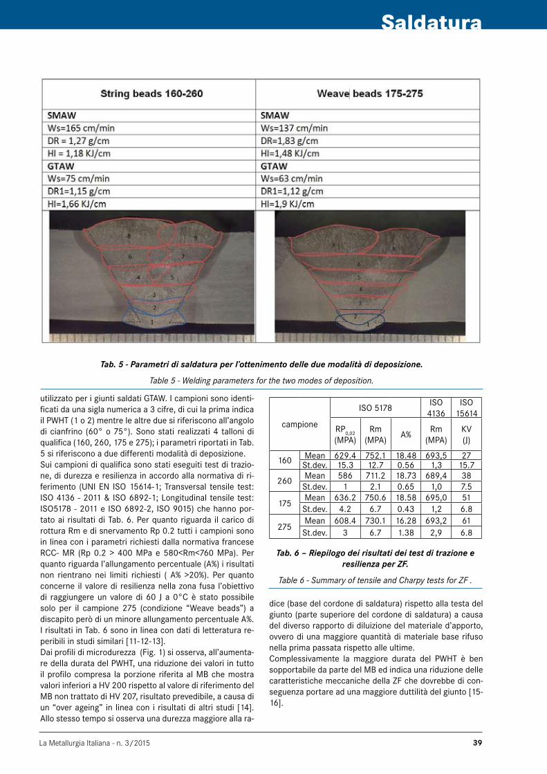
La Metallurgia Italiana - n. 3/2015 39
Saldatura
utilizzato per i giunti saldati GTAw. I campioni sono identi-ficati da una sigla numerica a 3 cifre, di cui la prima indica il PwHT (1 o 2) mentre le altre due si riferiscono all’angolo di cianfrino (60° o 75°). Sono stati realizzati 4 talloni di qualifica (160, 260, 175 e 275); i parametri riportati in Tab. 5 si riferiscono a due differenti modalità di deposizione. Sui campioni di qualifica sono stati eseguiti test di trazio-ne, di durezza e resilienza in accordo alla normativa di ri-ferimento (UNI EN ISO 15614-1; Transversal tensile test: ISO 4136 - 2011 & ISO 6892-1; Longitudinal tensile test: ISO5178 - 2011 e ISO 6892-2, ISO 9015) che hanno por-tato ai risultati di Tab. 6. Per quanto riguarda il carico di rottura Rm e di snervamento Rp 0.2 tutti i campioni sono in linea con i parametri richiesti dalla normativa francese RCC- MR (Rp 0.2 > 400 MPa e 580<Rm<760 MPa). Per quanto riguarda l’allungamento percentuale (A%) i risultati non rientrano nei limiti richiesti ( A% >20%). Per quanto concerne il valore di resilienza nella zona fusa l’obiettivo di raggiungere un valore di 60 J a 0°C è stato possibile solo per il campione 275 (condizione “weave beads”) a discapito però di un minore allungamento percentuale A%. I risultati in Tab. 6 sono in linea con dati di letteratura re-peribili in studi similari [11-12-13]. Dai profili di microdurezza (Fig. 1) si osserva, all’aumenta-re della durata del PwHT, una riduzione dei valori in tutto il profilo compresa la porzione riferita al MB che mostra valori inferiori a HV 200 rispetto al valore di riferimento del MB non trattato di HV 207, risultato prevedibile, a causa di un “over ageing” in linea con i risultati di altri studi [14]. Allo stesso tempo si osserva una durezza maggiore alla ra-
Tab. 5 - Parametri di saldatura per l’ottenimento delle due modalità di deposizione.
Table 5 - Welding parameters for the two modes of deposition.
campione
ISO 5178ISO
4136ISO
15614
RP0,02
(MPA)Rm
(MPA)A%
Rm(MPA)
KV(J)
160 Mean 629.4 752.1 18.48 693,5 27 St.dev. 15.3 12.7 0.56 1,3 15.7
260 Mean 586 711.2 18.73 689,4 38 St.dev. 1 2.1 0.65 1,0 7.5
175Mean 636.2 750.6 18.58 695,0 51 St.dev. 4.2 6.7 0.43 1,2 6.8
275Mean 608.4 730.1 16.28 693,2 61 St.dev. 3 6.7 1.38 2,9 6.8
Tab. 6 – Riepilogo dei risultati dei test di trazione e resilienza per ZF.
Table 6 - Summary of tensile and Charpy tests for ZF .
dice (base del cordone di saldatura) rispetto alla testa del giunto (parte superiore del cordone di saldatura) a causa del diverso rapporto di diluizione del materiale d’apporto, ovvero di una maggiore quantità di materiale base rifuso nella prima passata rispetto alle ultime. Complessivamente la maggiore durata del PwHT è ben sopportabile da parte del MB ed indica una riduzione delle caratteristiche meccaniche della ZF che dovrebbe di con-seguenza portare ad una maggiore duttilità del giunto [15-16].

La Metallurgia Italiana - n. 3/201540
Memorie
Fig. 1 – Confronto fra i profili di durezza alla testa (Cap) ed alla radice ( Root ) delle saldature.
Fig. 1 - Comparison of profiles hardness to the head ( Cap ) and the root (Root ) weld joint.
sALdAtuRA gtAW
L’intervallo di parametri investigati per la realizzazione del processo sono riportati in Tab. 7:
Mode I V ws [mm/min]
wfs [mm/min]
HI[kJ/mm]
DR [g/cm]
N. Pass Smusso
LDR230 12 120 660 1,38 0,34 18 75230 13 120 660 1,50 0,34 18 75
TDR
230 11,3 120 1750 1,30 0,89 8 75230 12,4 120 1750 1,43 0,89 8 75250 13,5 144 1980 1,41 0,84 7 60250 13 144 1980 1,35 0,84 7 60
HDR250 12 120 1980 1,50 1,01 6 60250 12,5 120 1980 1,56 1,01 6 60
Tab. 7 – Set-up dei parametri di saldatura (LDR: Tasso di deposizione basso, TDR: Tasso di deposizione bersaglio, HDR: Tasso di deposizione alto. Ws :
Velocità di saldatura (Welding Speed, Wfs: Velocità del filo d’apporto (Welding filler speed).
Table 7 - Welding parameter set-up (LDR: Low deposition ratio, TDR: Target deposition ratio, HDR: High deposition
ratio. Ws: welding speed, Wfs: Welding filler speed.
L’analisi di questo primo piano sperimentale, realizzato con un HI similare ma diverso DR e differente angolo di cianfrinatura riproducendo il tipo di deposizione “String Beads” V75; “weave Beads” V60, è avvenuta essenzial-mente attraverso test di durezza, analisi metallografica e radiografica. In Tab. 8 sono riportate le microstrutture del metallo base (BM), della zona di transizione (ZTA-ZF) e della zona fusa (ZF) ottenuta per i giunti nelle condizioni di LRD e TRD. Mentre sul MB la differente durata del trattamento termi-co non mostra differenze di microstruttura apprezzabili, nella ZF si osserva come la microstruttura, pur presen-tandosi in entrambi i casi come una martensite lamellare rinvenuta, questa sia molto più omogenea nel caso di LDR rispetto al caso TDR in accordo a quanto riportato in let-
teratura [17-18].In questo caso, comparando i profili di durezza fra le con-dizioni di LDR e TRD si osserva che a parità di trattamen-to termico si hanno valori paragonabili di durezza mentre solo in corrispondenza della radice del cordone si verifica un leggero slittamento (Fig. 2) che è dovuto alla maggiore larghezza della ZF in virtù del maggiore angolo di cianfri-natura.Ciò fa presumere che il parametro che maggiormente in-fluenza la durezza e le caratteristiche del
Le piastre di qualifica finali sono state realizzate con i pa-rametri della tabella seguente (Tab. 9), fissando il DR al va-lore di riferimento (0,67 g/cm), scelto come buon compro-messo fra produttività ed omogeneità della microstruttura. Anche in questo caso, anche a parità di DR. è stato deciso di verificare l’influenza del modo di deposizione a cordoni stretti/larghi variando contestualmente il ws e wfs, utiliz-zando differenti HI.
Id I(A) V(V)ws
(mm/min)wfs
(mm/min)HI
(KJ/mm)N.pass.
D.R.(g/cm)
Bevel
G75xy 230 12 120 1320 1,41 11 0,67 75°G60xy 250 12 90 990 1,84 8 0,67 60°
Tab. 9 - Parametri finali GTAW
Table 9 - Final parameter GTAW
Dai profili di durezza realizzati sui campioni ottenuti utiliz-zando i parametri della Tab. 9 (G60xy, G75xy) si può evi-denziare che in analogia a quanto accadeva per i campioni realizzati con SMAw il trattamento termico prolungato 4h riduce il valore di durezza.
I profili realizzati con un carico di 200 gf mettono bene in luce una delle problematiche maggiori della saldatura di questo tipo di acciai ovvero la formazione di una zona di softening all’interfaccia fra MB e ZTA, evidenziate nei grafici, che è origine delle cosiddette rotture “type IV cra-cking”.

La Metallurgia Italiana - n. 3/2015 41
Saldatura
Tab. 8 – Confronto microstrutture LDR-TDR. - Table 8 - LDR-TDR microstructures comparison.
Fig. 2 – Confronto fra i profili di durezza a parità di PWHT.
Fig. 2 - Comparison of profiles hardness with same PWHT.

La Metallurgia Italiana - n. 3/201542
Memorie
Fig. 3 – Profili di durezza in funzione delle differenti condizioni di saldatura e PWHT.
Fig. 3 - Hardness profiles as function of different welding conditions and PWHT.
Nella Fig. 4 è riportata la sezione macrografica tipica dei giunti realizzati a parità di DR e differente HI. Allo stesso modo di quanto fatto per le saldature SMAw, sui giunti GTAw sono stati effettuati test di trazione, di durezza e resilienza (Tab. 10) . In aggiunta sono stati realizzati anche test di trazione longitudinale alla temperature di 550°C (Tab. 11), temperatura di test richiesta per il BM dal RCC-MR.
Fig. 4 - Macrografia giunto “Bersaglio”.
Fig. 4 - Macrography of Target joint.
campione
ISO 5178ISO
4136ISO
15614
RP0,02
(MPA)Rm
(MPA)A%
Rm(MPA)
KV(J)
G601MeanSt.dev.
682,5 790 17,6 701,6 145,71,3 1,1 0,1 3,4 5,5
G602MeanSt.dev.
666,3 772,1 17,8 689,5 1676,4 4.2 0,3 2,0 11,4
G751MeanSt.dev.
696,8 796,2 17,0 697,8 150,76,8 0 0.1 5,3 13
G752MeanSt.dev.
680,8 781,3 17,9 703,9 171,314,2 10,6 1,6 3,3 5,5
Tab. 10 – Riepilogo dei risultati dei test di trazione e resilienza per ZF.
Table 10 - Summary of tensile and Charpy tests for ZF
campione
ISO 5178
Rp 0,2
(Mpa)
Rm(MPA)
A%
G602TMeanSt.dev.
429,8 453,5 21,8
1,9 1,5 0,8
G752TMeanSt.dev.
429,7 451,4 20,2
4,3 1,5 0,6
Tab. 11 - Riepilogo dei risultati dei test di trazione effettuati a 550°C.
Table 11 - Summary of tensile tests at 550 ° C.
Nei test eseguiti a temperatura ambiente, la FZ mostra valori molto elevati di Rm che non risultano conformi ai re-quisiti della RCC - MR ( Max 760 MPa ) previsti per il BM. Al tempo stesso l’allungamento, come mostrato per il SMAw, è superiore al 17 % , promesso dal materiale di riempimen-to utilizzato, ma inferiore alla soglia del 20 % richiesta per il BM. L’influenza del tempo di mantenimento del PwHT sulle caratteristiche dei giunti è uguale a quanto osservato per i campioni SMAw: si ottiene una riduzione della resi-stenza e un aumento dell’allungamento, all’aumentare del tempo del PwHT. La prova effettuata a 550 ° C presenta valori di Rp 0,2 più elevati di quanto richiesto (260 MPa) e l’allungamento è superiore al 20 %. Per la prova di resilien-za si registrano valori più elevati rispetto a quelli ottenuti con tecnica SMAw (circa il doppio) largamente in accordo con quanto richiesto dalla normativa (60 J /0°C).

La Metallurgia Italiana - n. 3/2015 43
Saldatura
AnALisi fiMec
Ad integrazione dei dati sperimentali ottenuti su diversi campioni saldati mediante tecnica SMAw sono state effet-tuate ulteriori caratterizzazioni, mediante controlli di tipo non distruttivo, con la tecnica di indentazione strumentata FIMEC (Flat-top Cylinder Indenter for MEchanical Charac-terisation) [19]. Il test FIMEC è una prova di indentazione strumentata che impiega un indentatore di geometria ci-lindrica a testa piatta in wC sinterizzato di raggio pari a 0,5 mm e permette di determinare alcune delle principali proprietà meccaniche di un materiale metallico. Il FIMEC consente di ricavare le caratteristiche tensili di un mate-riale metallico in corrispondenza delle zone in cui possono avere luogo variazioni locali delle proprietà meccaniche come nel caso delle diverse zone di un giunto saldato. La penetrazione della punta nel materiale da esaminare avviene a velocità costante (0,1 mm/min). Nel corso della prova si registrano il carico e la profondità di penetrazio-ne. Dividendo il carico per l’area della punta si ottengono curve pressione-penetrazione con un andamento caratte-ristico.Sono stati realizzati test di indentazione in 3 diverse zone del campione P91-260 (MB, ZTA e Saldatura). Dall’analisi FIMEC è stato possibile valutare la tensione di snervamen-to mediante l’algoritmo descritto in [20]. Le curve FIMEC ottenute ed i valori di tensione di snervamento associati sono riportati in Fig. 5. Tali valori sono stati confrontati con quelli ottenuti da test standard di trazione condotti su provini estratti dal BM e dal cordone di saldatura e ripor-tati in Tab. 6. Questi dati confermano quanto ottenuto con le prove di trazione e forniscono informazioni addizionali sulla ZTA.
concLusioni
In questo lavoro è stata investigata la saldabilità dell’accia-io P91 con tecnica SMAw e TIG automatizzata in funzione dell’influenza dei parametri di saldatura e del trattamento termico post saldatura (PwHT), con l’impiego di materia-li d’apporto, candidati alla saldatura di componenti, con qualificazione nucleare secondo le normative di riferi-mento. L’analisi ha messo in evidenza che i parametri di saldatura uniti ai trattamenti PwHT effettuati su i saggi con SMAw inducono nella ZF una notevole riduzione della resilienza misurata con test Charpy, come anche la dutti-lità mostra un allungamento percentuale che per quanto superi il limite minimo promesso dal filler material MTS3 (17%) difficilmente va oltre al 18%. Mentre è stato verifica-to come il trattamento termico a maggiore durata influen-zi notevolmente la resilienza portando a superare i limiti imposti per i componenti N1x nel caso dei parametri 275 ovvero cordoni larghi e apporto termico elevato, la duttilità del giunto non sembra essere influenzata sufficientemente dalla durata del PwTH. Per i saggi realizzati con tecnica GTAw, in analogia a quan-to visto per i campioni saldati con tecnica SMAw, l’analisi dei profili di durezza confermano come il parametro che
Fig. 5 - Curve di indentazione FIMEC e valori di tensione di snervamento ottenuti su tre diverse zone
del provino P91-260 (BM, ZTA e Saldatura).
Fig. 5 - Indentation FIMEC curve and values of yield stress obtained on three different areas of the specimen P91-260
( BM , HAZ and ZF ) .
più influenza i valori è la durata del PwHT rispetto al modo di deposizione. Anche per i campioni realizzati con tecnica GTAw l’allungamento è stato inferiore del 20 % , mentre si sono ottenuti buoni risultati in termini di resistenza e tenacità del giunto. Alla luce dei risultati ottenuti, l’aumento del tempo del PwHT sembrerebbe essere la chiave per ottenere valori di allungamento pari o superiori al 20 % ,anche se ciò com-porta una maggiore probabilità della formazione del “Type IV cracking”. Saranno necessari dei dati, relativi a test di creep, per comprendere appieno se una riduzione del valore soglia dell’allungamento è ammissibile, e prendere in conside-razione un adeguamento della RCC-MR con valori meno stringenti per le saldature rispetto al materiale base preso come target per questo lavoro.Le prove FIMEC dimostrano come sia possibile ottenere delle informazioni attendibili sulle proprietà meccaniche del giunto. Queste associate a rilievo di profili di durezza ed a repliche metallografiche su saldature di componenti in esercizio, possono essere un valido strumento per ot-tenere dei dati sulla durata di vita residua di componenti, ad esempio monitorando le caratteristiche nel tempo delle zone “type IV cracking”.
BiBLiogRAfiA
1] D.R. HARRIES, R. L. KLUEH, High-Chromium Ferritic and Martensitic Steels for Nuclear Applications, ASTM stocK number: mono3 (2013).
2] J.I. COLE, J.L. REMPE, T.C. TOTEMEIER, G.S. wAS, K. SRIDHARAN, T. ALLEN, J. JANG, S. HONG, Developing and Evaluating Candidate Materials for Generation IV Supercritical water Reactors, Technical report, INL (2006).

La Metallurgia Italiana - n. 3/201544
Memorie
3] A. CAMMI, S. CONCARI, Metodi di prova di materia-li esposti a metalli liquidi, Rapporto Tecnico,RSE, (2011).
4] T. LIRATZIS, Rivista italiana della saldatura, No.2 (2010), p.16.
5] A.TONTI, Main issues for use P91in nuclear power plants, Atti di European Nuclear Conference Barcello-na, (2010).
6] R.E. MIZIA , Next Generation Nuclear Plant Reactor Pressure Vessel Acquisition Strategy, Technical report, INL (2008).
7] C. PANAITS, w. BENDICK, A. FUCHSMANN, J. BESSON, A.-F. GOURGUES–LORENZON, International Journal of Pressure Vessels and Piping 87 (2010), p. 326.
8] H. HUESER, Properties of matching filler metals T91/P91, EPRI-RRAC, Atti di Fifth International Conferen-ce of welding and Repair technology for power Plant, (2002).
9] M. L. SANTELLA, R. w. SwINDEMAN, R. w. REED, J. M. TANZOSH, Martensite transformation, microsegre-gation, and creep strength of 9 Cr-1 Mo-V steel weld metal, Atti di Trends in welding Research-International Conference, (2003).
10] R. SINGH, M.S., IENG, MwELDI, Pipeline & Gas Journal, vol.238 No.10 (2011).
11] B. SILwAL, L. LI, A. DECEUSTER, B. GRIFFITHS, wel-ding Journal, Vol. 92 (2013), p. 80.
12] D.P. SINGH, M. SHARMA, J.S. GILL, IJRMET Vol. 3 (2013), p. 216.
13] G. TANIGUCHI, K. YAMASHITA, Effects of Post weld Heat Treatment (PwHT) Temperature on Mechanical Properties of weld Metals for High-Cr Ferritic Heat-Resistant Steel, welding in the world, vol.56 (2012), p.81.
14] A. MCGEHEE, K. COLEMAN, Optimal Hardness of P91weldments, EPRI, Technical Report (2003).
15] P. DE SMET, H. VAN wORTEL, welding Journal, vol.85 (2006), p.42.
16] A. DIMATTEO, Rivista italiana della saldatura, No.2 (2012), p.153.
17] B.ARIVAZHAGAN, R.PRABHU, S.K. MARARAJ, S.SUNDARESAN, Journal of Materials Engineering & Performance , vol.18 (2009), p.999.
18] T. VUHERER, M. DUNDER, LJ. MILOVIC, M. ZRILIC, I. SAMARDZIC, METALURGIJA 52 (2013), p. 317.
19] B. RICCARDI, R. MONTANARI, Materials Science & En-gineering A, 381/1-2 (2004), p. 281.
20] L. CIAMBELLA, R. MONTANARI, Materials Science Fo-rum, Vol. 783-786 (2014), p. 2272.
influence of welding parameters on microstructure of welded joints sMAW/gtAW steel x10 crMoVnb 9-1 (P91)
Keywords: Stainless steel - welding - Mechanical test - Non destructive test - Selecting materials
This paper presents weldability results of P91 creep resistant steels performed through two different welding techno-logies: the “ fully mechanized (GTAw)”, and the “Shielding Metal Arc welding (SMAw)”It was evaluated the influence of welding parameters on the microstructure of the joint and on the consequent mecha-nical characteristics (Strength, toughness and ductility) of the fused zone (ZF). with reference to the P91 creep resistant steel (Tab.1), the RCC-MRx code for the design and production of compo-nents for nuclear power plants, have data sheet about the chemical and mechanical features of “Base Material” (BM) but does not have data sheet about filler materials, as qualified for welding nuclear components class 1.Scope of this work is to evaluate possible candidate filler material (Tab.2) and to suggest welding technologies and related operative welding conditions to ensure that N1 class could be produced with the same requirements as the Base Material, in compliance to the design code.The main objective of this study is to evaluate the candidate filler materials and suggest welding conditions optimized for PwTH, Heat Input (HI), and Deposition Mode/Ratio(DM/DR), to obtain an elongation of more than 20 % and a toughness of more than 60 J to 0°C (as evaluated by Charpy KV test)in the fused zone (ZF).For both processes, according to the literature data, it was decided to analyze the influence of four parameters: speed of deposition (deposition ratio DR ); mode of deposition (DM); Heat input (HI ); duration of PwHT . To varying DR/ DM were chosen two different bevel angles (60 ° and 75 °), two modes of deposition (“ String Beads”, “ weave Beads “), obtained through different welding speed ws. Two different holding times (2h , 4h ) for PwHT were investigate to evaluate the influence of Time on the feature of FZ.The test was carried out in compliance within the RCC- Mr and the correlate ISO Standard: ( UNI EN ISO 15614-1 ; Transversal tensile test : ISO 4136-2011 & ISO 6892-1 ; Longitudinal tensile test : ISO5178 - 2011 and ISO 6892-2 , ISO 9015). The Data about the performed test are reported in Tab. 6.In general for both the welding technology evaluate, the Fused Zone as welded have a fully martensitic microstructu-res, this is demonstrated by the high value of hardness. After the PwHT the hardness in FZ decreases from more of

La Metallurgia Italiana - n. 3/2015 45
Saldatura
400 to 230-250 HV5, typical values of tempering martensite. The comparison between the hardness profiles measured at different conditions and PwHT show that the duration of the holding time influences the hardness (Fig.1). If the hol-ding time increases the hardness in FZ decreases.About SMAw, the toughness improves with increasing the holding time of the PwHT. However only for the condition of welding “weave beads” the value is in compliance with the RCC- MR (Tab. 6). In general, a little reduction of tensile strength was observed after the PwHT, and the differences increase with the increase in holding time. At the same way, the test on GTAw coupons, confirming that longer PwHT holding time induces a reduction in the hardness of fused zone.The micro hardness test highlighted the well know problem of softening in the interface between of HAZ and BM, where the material was subjected to an unavoidable over-tempering (Fig.3).The V notch Charpy tests on GTAw weld shown very high values (higher than SMAw ) in all the case in compliance with the requirement of RCC-MR.The longitudinal tensile test at room temperature for GTAw ZF specimens (Tab.10), shows very high values of Rm than SMAw. However, this high values are not in compliance with the requirements of the RCC-MR (Max 760 MPa).At the same time the values of elongation, both for GTAw and SMAw processes, is more than 17%, which is promising for a filler material but less than the 20%, threshold required for the BM and the target for the welds. The influence of holding time of PwHT on the mechanical features is the same for the two processes analyzed. The strength is reduced and the elongation increased with augment of holding time of the PwHT. The longitudinal tensile test at 550°C were performed only for the GTAw coupons and shown values of Rp 0,2 more than required (260 MPa) and an elongation more than 20 (Tab.11).. The SMAw and GTAw shown that the “weave beads” Deposition Mode allowed obtaining the best results in terms of toughness and ductility. The holding time of PwHT influenced the toughness, hardness and strength of the welds. The holding time of 4 h appear to allow the best results. The elongation in all tests for processes at room temperature were less than 20 %. The fully mechanized GTAw showed values of strength very high in association with very good toughness. In all the processes two main problem remain: The softening zone between HAZ and BM (Type IV Cracking zone); The elongation less than 20% , which is requested for the Base Material.Values of elongation of 17-18% are commonly achievable from a wide range of processes and welding parameters. To increase this value, the augment of the PwHT holding time seems to improve the elongation but a long time of PwHT means a higher over-tempering of the Type IV Cracking zone.So, in conclusion, the filler material used in this work is a good candidate to weld Nuclear component made of P91, however the target in terms of ductility and maximum strength, required as BM of RCC-Mr, needs to be reviewed.

6th International Conference
STEELSIM2015
BARDOLINO, ITALY23-25 SEPTEMBER 2015
Modelling and Simulation of metallurgical processes cover an important role in optimizing technological processes, decreasing production costs, increasing steel quality and defining the correct design of metallurgical processes in order to improve their sustainability even from the environmental point of view. The fundamentals of metallurgical processes can be investigated through physical and numerical modelling following several numerical approaches. Traditional and new mathematical techniques applied by modern simulation facilities allow to achieve results that are useful to understand physical interaction and to design a profitable metallurgical process. The simulations technique can be applied to the different steps of the metallurgical production route: production and refining of liquid metals, solidification, plastic deformation, thermo-mechanical processes, thermal treatment, verification of structural reliability etc.
CONFERENCE TOPICSState of art and developments in modeling and simulation in steelmaking:• Ironmaking• Primary metallurgy (aluminium alloys, copper alloys
titanium alloys etc.)• Secondary steelmaking• Refining of metal alloys• Thermodynamic and kinetic simulation of the metallurgical
systems • Casting and solidification• Electrochemical processes• Metalforming processes and thermo-mechanical treatment• Heat treatments• Fracture mechanics and safety criteria• Fatigue mechanics• Safety criteria• Reduction of environmental impact
EXHIBITION & SPONSORSHIP OPPORTUNITIESSteelSim 2015 will feature an Exhibition that will enable excellent exposure for company products, technologies, innovative solutions or services. Companies will also be able to become Sponsors of the Conference. Companies interested in taking part in the Exhibition or in sponsoring the event may contact the Organising Secretariat (e-mail: [email protected] / fax: +39 0276020551).
VENUEThe Conference will be staged at the Congress Center of Aqualux Hotel Spa Suite & Terme, in Bardolino (VR), ItalyVia Europa Unita, 24/b 37011
www.aimnet.it/steelsim2015.htm
ORGANIZING SECRETARIAT
AIM - ASSOCIAZIONE ITALIANA DI METALLURGIAP.le R. Morandi, 2 · 20121 Milano · Italy · tel. +39 02 76021132 · fax. +39 02 76020551
e-mail: [email protected] www.aimnet.it
Organised by ASSOCIAZIONE ITALIANA DI METALLURGIA
MODELLING and SIMULATION of METALLURGICAL PROCESSES in STEELMAKING

La Metallurgia Italiana - n. 3/2015 47
Trattamenti superficiali
Marcello cabibbo Dipartimento di Ingegneria Industriale e Scienze
Matematiche (DIISM),Università Politecnica delle Marche, Via Brecce Bianche, 60131 Ancona
ZnO nanowires are currently used in many application fields, such emission displays, dye-sensitized solar cells, gas sensors, nanomachines, to cite but few. Thermal stability is often a concern in terms of the mechanical
response and, in particular, for the elasticity of the nanowires. Literature works focused to a certain degree, on the heating response of nanowires. Anyhow, no experimental data are nowadays available in literature on the low- and very low-temperature exposures. In the present study, deep-cryogenic treatment was performed on vertically
aligned ZnO nanowires produced by metal organic chemical vapor deposition. The mechanical response of the nanowires was detected by nanoindentation tests. It was found that the Young’s modulus, the critical buckling stress and strain of individual nanowires is not significantly influenced by the cryogenic exposure. Yet, the bulk
base ZnO from which the nanowires are grown halved after the deep-cryogenic treatment.
Keywords: ZnO nanowires - ZnO coatings - Nano-structured coatings - Deep-cryogenic treatment
intRoduction
Zinc oxide (ZnO) has drawn considerable interest because-of its semiconducting and piezoelectric properties [1-3]. In particular, ZnO nanostructures have applications asfield-ef-fect transistors [4], gas sensors [5], field-emission displays [6], and nano-electromechanical systems (NEMS) [7]. All of theseapplications require the knowledge and the ability to controlthe mechanical behavior of ZnO nanostructures. ZnO possesses one of the richest family of nanostructures [3,8].ZnO has some advantages over the other above men-tioned nanostructures as it exhibits both semiconducting and piezoelectric properties, and it can be grown in a wide variety of geometrical configurations [9].Due to the reported high elastic modulus and high aspect ratio, a further potential application of ZnO Nws is as tips for atomic force microscopy. It has also been shown that thesematerials are potential useful for nanoscale interconnects,active components of optical electronic devices andnano-electromechanical systems. For these reasons, it is importantto understand mechanical charac-
teristics of the ZnONws[1,9-15].Presently, there are many reports on themechanical pro-perties of ZnO Nws [16-18]. Recent experimental findings [18] reportedmodels to determining the buckling of ZnO Nws under uniaxial compression, and proposed a new method to observe thecritical load, elastic modulus, and stress or strain of the Nws based on the Euler or Johnson buckling theory.There are several techniques that have been developed for measuring the elastic properties of individualNw. The technique first introduced by wong, Sheehan, Lieber [1] is based on quantifying the deflection of a single nanowireaf-fixed at one end with the other end left free to be deflected by an atomic force microscope tip. The Nws were laid in parallel to a solid substrate, and the elastic modulus was calculated from the force-deflection curve.Moreover, me-chanicalproperties of ZnO and similarNws have been ex-tensively studiedby tensile loading, bending, and buckling [19].The study of nanoindentation on a vertically aligned na-nowires (VANw) forest reveals a process whereby Nws are consecutively bent during the penetration of the indent tip. Therefore, the resistance of a VANw forest to penetra-tion is due to successive bending of Nws as the tiptouches theNws. Using a micro-mechanical model of the indenta-tion process, the effective bending stiffness of constituent Nws in the VANw array is then deduced from nanoinden-tation force-penetrationdepth curves (essentially using the
zno nanowires grown on bulk zno coatings:mechanical response to deep cryogenic
treatment
M. cabibbo

La Metallurgia Italiana - n. 3/201548
Memorie
classical Oliver and Pharr approach, see [20] to cite but one) [21]. Furthermore, when the size of a material is redu-ced to the nanoscale, owing to the large surface-to-volume ratio, surface effects will play important roles in the nano-structures. The theory of surface elasticity proposed by Gurtinet al. [22] has been widely employed and developed to account for the surface effects on nanoscale elements.Different techniques have been used to grow ZnO Nws, such as laser ablation [23], chemical vapor deposition me-thod, electro-deposition method, vapor phase transport [11-14], thermal evaporation using ZnO powders [15], low-temperature liquid-phase deposition [24], vapor–liquid–solid deposition [25], electrochemical decomposition, which is a less onerous technique used in industry [26], and metal organic chemical vapor deposition (MOCVD) [14,27,28]. In this research work, ZnO Nws were grown by MOCVD in a Si-(100) substrate. In this work, the influence of a deep cryogenic treatment on MOCVD ZnO Nws mechanical pro-perties such Young’s modulus and hardness was studied.
exPeRiMetAL detAiLs
A vertical chamber MOCVD systemwas employed for the catalyst-free synthesis of theZnO Nws. Si-(100) wafer was used as thesubstrate. High-purity diethyl zinc (puri-ty >99.99%), and N2O (purity >99.99%) were used as zinc and oxygensources, respectively, and nitrogen as the car-rier gas.The diethyl zinc was kept at room temperature. The basepressure of the reactor chamber was 105 Torr, the working pressure being 40 Torr. The ZnO Nwswere grown via a two-step process. First, a thinnucleation layer of ZnO was grown at a temperature of 400°C. Thence, ZnO Nws were grown on the annealed nucleationlayer at a temperature of 650°C and for a total duration of 30 min. The elastic properties and hardness of the vertical aligned ZnO Nws were measured by an indentation method [21] in which a tip was pushed downward against the aligned Nws so that many Nws are in contact with the tip (at least 30 individual Nws). By measurement of the force-displa-cement curve, and the average number of Nws that were in contact with the tip, an average elastic modulus and hardness estimation of the Nws is possible. This method requires that the density of the Nws is high and all of the Nws have the same size and length. To obtain statistically reliable data, different regions of the ZnO Nws were tested at different tip loads. Thus more than 100 measurements were carried out and the data reported hereafter were averaged over all the processed load-unload curves. Raw data analysis was performed according to the Oliver and Pharr method (readers interested to have more details on this widely used method of data analysis are referred to [20,29] and actually to the many other literature papers on nanoindentation data analysis). According to the round robin experiment results reported in [29], a trapezoid load function (loading time of 20 s, holding at the peak load for
60 s, followed by 3 s unloading to the 10% of the peak load, and a final 60 s holding at this load).The Si/ZnO Nws samples were subjected to a cryogenic treatment consisting of a cooling from room temperature to -196°C at a rate of 1°C/min, holding at -196°c for 120 min, and slow recover to room temperature at same rate used for the cooling process.A Hysitron©Inc. triboscope nanoindenterUbi®-1 was used to determine the Young’s modulus and hardness of the ZnO Nws prior and after a cryogenic treatment. A unia-xial compression onto the ZnO Nwswas exerted by a 3-si-ded pyramidal Berkovich tip (with edge aperture angle of 65.35°, and radius of curvature of 150 nm).Samples surface morphology and size distribution of the Nws before andafter the cryogenic treatment and the na-noindentation tests were characterized by a Zeiss© Supra®-40 field emission scanning electron microscope(FESEM), operated at 5 KeV.
exPeRiMentAL ResuLts And discussion
Fig. 1 shows a cross-section FESEM image recorded at a 30° tilt angle of the as-grown ZnO Nws. It can be seenthat ZnO Nws are densely well-aligned with uniform diameter. Mean diameter, length and density of these Nws were 80 ± 5 nm, 1000 ± 80 nm, and 7.15·109 cm-2, respectively. As shown in the Figure 1 inset, ZnO Nws were grown with an hexagonal structure.
Fig. 1 - Cross-section FESEM image recorded at a 30° tilt angle showing diameter, length, and distribution of the as-grown ZnO NWs. Inset is a top-view showing the
grown structure of the present ZnO NWs, which are hexagonal.
Fig. 2 reports a top-view FESEM micrograph of the de-ep-cryogenic treated Nws after nanoindentation test. It can be seen that these Nws were severely distorted and collapsed to the basement layer. Since these tests were destructive, several tests were carried out at different lo-ads and in different ZnO Nws regions to ascertain the re-producible of the method. Results yield a full and reliable reproducibility of the method.

La Metallurgia Italiana - n. 3/2015 49
Trattamenti superficiali
A typical continuous load–unload force–displacement curve for as-grown and cryogenic treated Nws is shown in Figure 3. This figure clearly illustrates that multiple di-scontinuities, i.e. pop-in events, in the force–displacement curves occur during loading, in both cases, the as-grown Nws (Fig. 3(a)), and the deep-cryogenic treated condition (Fig. 3(b)). No discontinuities have been observed on un-loading. Results show that the critical load for the first pop-in, that is the elastic-plastic threshold value, essen-tially varies in the range of 300-480 μN, in both conditions. More specifically, the as-growth Nws showed a average elastic-plastic threshold load value of 390 μN, and after cr-yogenic treatment this mean value was of 410 μN, that is, the mean critical load did not changed significantly after cryogenic treatment. In either cases, varying the applied load (in the range of 1 to 3.5 mN) the analysis of nanoin-dentation curves also revealed that the larger the load re-quired for the first pop-in to occur, the larger the length
Fig. 2 - FESEM top-view of the deep-cryogenic treated ZnO NWs after a nanoindentation test (applied load of
7 mN, triangular pyramidal Berkovich tip).
Fig. 3 - Six representative load-displacement nanoindentation curves showing the pop-in event upon loading of the ZnO NWs in the as-grown condition (maximum loads ranging1.25- to - 3.0 mN), a), and after deep-cryogenic
treatment (cooling to -196°C at a rate of 1°C/min, holding at -196°c for 120 min, followed by 1°C/min slow recover to room temperature), where maximum loads ranged1.25-to-2.7 mN, b).
of indenter excursion during the pop-in event, i.e. larger penetration depth. As a result, the maximum penetration of the indenter is essentially independent of the number of pop-in events during loading.The loading portion of the load-displacement curves consi-st of three stages which can be recognized by the value of the critical load, Pcr: an initial load regime, where the load, P, increases (P < Pcr), followed by a sudden drop in the cur-ve slope, which eventually becomes flat at P = Pcr, and a third stage,where the load starts back to increase with the penetration depth, P > Pcr. The buckling instability occurs in the flat portion of the loading curve. It is well known that the behavior of an ideal column ofNws compressed by an axial load P can be summarized as follows: a. if P < Pcr, the column is in stable equilibrium in its straight position; b. if P = Pcr, the column is in a neutral equilibrium in either the straight or a slightly bent position; c. if P > Pcr, the column is in unstableequilibrium in its straight position and will buckle under the applied load.Such a type of buckling is called Euler buckling [30].
Fig. 3 also shows large displacement versus load in the load range P<Pcr, which denotes a large flexibility of the ZnO Nws. This behavior was observed not only in the as-grown condition, but also, and surprisingly, after deep-cryogenic treatment.In particular, the value of the critical load, Pcr, is essentially the same in either the as-grown and cryogenic treated condition, this ranges from 300 to 480 μN, in the as-grown Nws, and from 360 to 440 μN, in the cryogenic treated condition. An interesting aspect is thus that the range of variability of the buckling critical load after cryogenic treatment is far more narrow, and limited to the upper value portion of the value range showed in the as-grown condition. The ranging values of the ZnO Nws critical load depend on the applied maximum load, and in most cases it rises with applied load, which ranged 1.0 to 3.5 mN. Moreover, the penetration depth reached to initia-

La Metallurgia Italiana - n. 3/201550
Memorie
te the critical buckling load in the cryogenic treated ZnO Nws was the same as to the as-grown ZnO Nws. It is well known that the high flexibility of the ZnO Nws is attributed to the low dimension of the structure. For instance, Chen et al. [10] showed that a pure single ZnO crystal of 100 nm diameter can be bent into a minimum of 1 μm diame-ter circle. Another reason may be due to the movement of the Nws at the ends support, as a perfect rigid support is impossible, which is thus not influenced by the cryogenic treatment.
The FESEM top-view, reported in Fig. 2, easily allows the estimation of the average critical buckling load of an indi-vidual ZnO Nw. As reported in Fig. 2, the area interacting with the indentation pyramidal tip is constituted by a equi-lateral triangle of 2 μm edge dimension (for typical applied loads of 2.5-3.5 mN), which slightly reduces to 1.7-1.8 μm in the lower load range (1.5-to-2.5 mN). The total ZnO Nws run over by the pyramidal tip are some 80. Thereafter, the critical buckling load of a single ZnO Nw is about 4.9 and 5.1 μN, in the as-grown and cryogenic treated conditions, respectively. The unchanged buckling load of ZnO Nws af-ter deep-cryogenic treatment is surely a remarkable result. This means that no change in the elastic-plastic properties of the ZnO Nws is induced by a cryogenic treatment.
Following the classical theory of elasticity of solids [33], the critical buckling load for an ideal elastic column can be expressed as (Euler load), Eq. (1):
(1) Pcr = p2EI/Leff2
where E is the Young’s modulus of an individual ZnO Nw, I = πD4/32 is the momentum of inertia, D the mean Nw diameter (this taken as the outer circumference of the Nw hexagonal section), Leff is the effective Nw length, which, for a fixed-pinned “cylindrical” Nw is 0.7L, L being the mean Nw length. The critical buckling strain is given by εcr = scr/E, where the critical buckling stress, scr = Pcr/A, A being the mean section area of the hexagonal Nws (A = (3√3/8)D2). Table 1 compiles the values obtained for the single ZnO Nw Young’s modulus, E, its critical buckling stress, scr, and strain, εcr, in the as-grown and deep-cryogenic tre-ated conditions. The quite close Young’s modulus values (86 GPa for the as-grown, and 90 GPa of the deep-cryo-genic treated single ZnO Nw), accounting for a slight 4% difference, clearly indicate a almost irrelevant influence of the cryogenic treatment in the elastic modulus of the ZnO Nws.The here obtained values are reasonably close to the re-ported elastic modulus of single-crystal ZnO bulk coating, beingE = 111 GPa as shown in [34]. The elastic properties of ZnO nanostructures and their size dependence have been previously investigated by means of transmission electron microscopy (TEM) [10] and atomic force microscopy (AFM) [30]. The Young’s modulus of ZnO Nws was found to de-crease dramatically with increasing diameter, reaching the
Pcr, μN
E, GPa
scr, MPa
εcr varia-tion,
%
as-grown 4.9 86 1192 0.014 -
deep-cryogenic treated
5.1 90 1241 0.014 4
Table 1. Single ZnO NW critical buckling load, Pcr, Young’s modulus, E, stress, scr, and strain, εcr, in the
as-grown and deep-cryogenic treated conditions.
ZnO bulk value for diameters typically larger than 120 nm. This behavior was attributed to a surface stiffening effect dominating at large surface-to-volume ratios [10]. The similar critical buckling stress in both conditions also means that hardness of individual ZnO Nws is not signifi-cantly modified after cryogenic treatment.
On the other hand, Oliver and Pharr analysis of the who-le load-unload curves allowed to determine the Young’s modulus and hardness of the ZnO Nws prior and after deep-cryogenic treatment. Anyhow, it must be emphasi-zed that the classical Oliver and Pharr analysis approach of the raw data allows to determine the Young’s modulus and hardness of the ZnO Nws, together with the basement from which they are grown. This is due to the fact that the third part of the loading curve, i.e. for P >Pcr, pertain to the ZnO coating basement, since the Nw buckling load has been exceeded. Due to the fact that the Oliver and Pharr analysis determination of the coating Young’s modu-lus and hardness are determined from the slope, i.e. the tangent, at the starting point of the unloading curve, the obtained value derives from both ZnO base and Nws. This holds unless the substrate of Si-(100) start to contribute to the measurements. This typically holds for penetration depths approaching 20-25% of the total coating thickness. In the present case, even the maximum applied load of 3.5 mN did not reach this limit (the penetration depth being of 3500 nm, under a ZnO base thickness of 20μm and Nw of 1 μm).
Curve analysis showed that the as-grown Nws Young’s modulus is Eas-grown, of 115 ± 25 GPa, which essentially dou-bled after deep-cryogenic treatment (Epost-cryo = 320 ± 10 GPa). On the other hand, hardness increased slightly in the deep-cryogenic treated condition, being Has-grown = 4.4 ± 0.4 GPa, and Hpost-cryo = 5.3 ± 0.3 GPa. Elastic modulus and hardness of the base bulk ZnO coating well agreed with literature data (see for instance [35]).Thence, the hardness-to-elastic modulus ratio, H/E, of the ZnO coa-ting, constituted by the base and Nws, almost halved after cryogenic treatment. Since, as shown above, the ZnO indi-vidual stress and Young’s modulus did increase of only 4% after deep-cryogenic treatment, the larger part of reduc-tion of the Young’s modulus as determined by the load-unload curve analysis is to be attributed to the bulk base ZnO coating. This indeed is an interesting result, as it was shown that, while the elastic modulus of the ZnO bulk co-

La Metallurgia Italiana - n. 3/2015 51
Trattamenti superficiali
ating halved after deep-cryogenic treatment, the ZnO Nws were practically not affected.
concLusions
In summary, it was reported that deep-cryogenic treatment of MOCVD ZnO Nws did not impair the large flexibility of the as-grown ZnO Nws. It also did not influence to a signi-ficant extent the Young’s modulus and the critical buckling load, stress , and strain. On the other hand, the Young’s modulus of the bulk ZnO base, from which the Nws were grown, halved after the deep-cryogenic treatment.
AcKnoWLedgMents
The authors wish to thank Mr. D. Ciccarelli for their help in performing the cryogenic treatment and nanoindentation tests.
RifeRiMenti BiBLiogRAfici
[1] Z.L. wANG,J.H. SONG, Science 312 (2006) 242.[2] M.-H. ZHAO,Z.L. wANG, S.X. MAO, Nano Lett. 4
(2004) 587.[3] Z.L. wANG, J. Phys. Condens. Matter 16 (2004)
R829.[4] X. wANG,J. ZHOU,J. SONG, J. LIU,N. XU,Z.L. wANG,
Nano Lett. 6 (2006) 2768.[5] M.S. ARNOLD, P. AVOURIS, Z.w. PAN, Z. wANG, J.
Phys. Chem. B 107 (2003) 659.[6] C.J. LEE, T.J. LEE, S.C. LYU, Y.ZHANG, H. RUH, H. LEE,
J. Appl. Phys. Lett. 81 (2002) 3648.[7] w.L. HUGHES, Z.L. wANG, Appl. Phys. Lett. 82 (2003)
2886.[8] A. DJURISIC, A. NG, X. CHEN, Prog. Quantum Elec-
tron. 34 (2010) 191.[9] H. ZHOU, M. wISSINGER, J. FALLERT, R. HAUSCHILD,
F.STELZL, C. KINGSHIRN, H. KALT, Appl. Phys. Lett. 91 (2007) 181112.
[10] C.Q. CHEN, Y. SHI, Y.S. ZHANG, J. ZHU, Y.J. YAN, Phys. Rev. Lett. 96 (2006) 075505.
[11] D.C. LOOK, Mater. Sci. Eng. B 80 (2001) 383.[12] S. MUTHUKUMAR, H. SHEN, J. ZHONG, Z. ZHANG,
N.w. EMANTOGLU, Y. LU, IEEE Trans. Nanotechnol. 2 (2003) 50.
[13] w. LEE, M.C. JEONG, J.M. MYOUNG, Acta Mater. 52 (2004) 3949.
[14] Z.R. DAI, Z.w. PAN, Z.L. wANG, Adv. Funct. Mater. 13 (2003) 9.
[15] Z.w. PAN, Z.R. DAI, Z.L. wANG, Science 291 (2010) 1947.
[16] C.Q. CHEN, J. ZHU, Appl. Phys. Lett. 90 (2007) 043105.
[17] S.J. YOUNG, L.w. LI, S.J. CHANG, T.H. FANG, T.J.
HSUEH, T.H. MEEN, I.C. CHEN, Nanotechnology 18 (2007) 225603.
[18] M. RIAZ, O. NUR, M. wILLANDER, P. KLASON, Appl. Phys. Lett. 92 (2008) 103118.
[19] M.F. YU, O. LOURIE, M.J. DYER, K. MOLONI, T.F. KEL-LY, R.S. RUOFF, Science 287 (2000) 637.
[20] w.C. OLIVER, G.M. PHARR, J. Mater. Res. 7 (1992) 1564.
[21] H.J. QI, K.B.K. TEO, K.K.S. LAU, M.C. BOYCE, w.I. MIL-NE, J. ROBERTSON, K.K. GLEASON, J. Mech. Phys. So-lids 51 (2003) 2213.
[22] M.E. GURTIN, J. wEISSMULLER, F. LARCHE’, Phil. Mag. A 78 (1998) 1093.
[23] B.M. ATAEV, I.K. KAMILOV, V.V. MAMEDOV, ,Tech. Phys. Lett. 23 (1997) 842.
[24] F. XU, Z.Y. YUAN, G.H. DU, T.Z. REN, C. VOLCKE, P. THIRY, B.L. SU, J. Non-Crystal. Solids 352 (2006) 2569.
[25] Y.S. ZHANG, K. YU, S.X. OUYANG, Z.Q. ZHU, Mater. Lett. 60 (2006) 522.
[26] Y. LEPRINCE-wANG, G.Y. wANG, X.Z. ZHANG, D.P. YU, J. Crystal Growth 287 (2006) 89.
[27] J.Y. PARK, D.J. LEE, Y.S. YUN, J.H. MOON, B.T.LEE, S.S. KIN, J. Crystal Growth 276 (2005) 158.
[28] Y.J. ZENG, Z.Z YE, w.Z. XU, L.P. ZHU, B.H. ZHAO, Appl. Surf. Sci. 250 (2005) 280.
[29] M. CABIBBO, P. RICCI, R.CECCHINI, Z. RYMUZA, J. SULLIVAN, S. DUB, S. COHEN, Micron 43 (2012) 215.
[30] w.J. MAI, Z.L. wANG, Appl. Phys. Lett. 89 (2006) 073112.
[31] L.w. JI, S.J. YOUNG, T.H. FANG, C.H. LIU, Appl. Phys. Lett. 90 (2007) 033109.
[32] S.J. YOUNG, L.w. JI, S.J. CHANG, T.H.FANG, T.J. HSUEH, Physica E 39 (2007) 240.
[33] S.P. TIMOSHENKO, J.M.GERE, Theory of Elastic Stabi-lity McGraw-Hill, New York, 1961, p. 46.
[34] S.O. KUCHEYEV, J.E. BRADBY, J.S. wILLIAMS, C. JAGA-DISH, M.V.SwAIN, Appl. Phys. Lett. 80 (2002) 956.

CONFERENCE&EXHIBITION20th - 21st - 22nd MAY 2015 MILANO
WE STEEL BELIEVE
L’EVENTO INTERNAZIONALE DEDICATO ALLA FILIERA DELL’ACCIAIO DALLA PRODUZIONE AL SUO UTILIZZO
LO STILE MADE IN ITALY PER TRE GIORNI DI BUSINESS E APPROFONDIMENTIPENSIAMO INSIEME ALL’ACCIAIO DI DOMANI
MADE IN STEEL 2015
IL PRINCIPALE EVENTO DEL SUD EUROPA DEDICATO ALL’ACCIAIO

La Metallurgia Italiana - n. 3/2015 53
Trattamenti superficiali
the effect of deep cryogenic treatment on hardness and wear behavior
of the H13 tool steel
K. Amini, M. negahbani, H. ghayour
Kamran AminiDepartment of Mechanical Engineering,
Tiran Branch, Islamic Azad University, Tiran, Iran* Corresponding Author: [email protected]
Tel. 00989131651659
Mehran negahbaniDepartment of Mechanical Engineering, Khomein
Branch, Islamic Azad University, Khomein, Iran
Hamid ghayourDepartment of Materials Engineering, Najafabad
Branch, Islamic Azad University, Najafabad, Isfahan, Iran
In recent decades, cryogenic treatment has been used as the finishing operation between the quenching and tempering treatment on tool steels for the purpose of increasing hardness and wear resistance. H13 tool steel is a hot working steel widely used in manufacturing molds and hot working tools. In this research, the effect of deep
cryogenic treatment at -196 for 24 hours has been investigated in comparison with the quenching-tempering treatment on hardness, structure and wear resistance. In addition, the effect of TiC coating after cryogenic
treatment on hardness and wear resistance has been studied. The results of this research showed that cryogenic treatment with or without coating leads to an increase in hardness levels of 5.7 % and 9.6 %, respectively, and
an improvement in the wear resistance levels of 33 % and 60 % respectively, in comparison with the quenching-tempering treatments. Investigating the wear surfaces by scanning electron microscopy (SEM) showed that the
wear mechanism is adhesive.
Keywords: Deep cryogenic treatment - H13 tool steel - Hardness - wear behavior
intRoduction
The martensitic transformation start and finish temperatu-res in steels are reduced by increasing the percentages of carbon and the alloying elements. Even in high-alloy steels with high carbon contents, the martensitic transformation finish temperatures may reach less than zero degrees Cel-sius. Because of this, the retained austenite will exist in the steel structure after quenching to the environmental temperature. Retained austenite is a soft phase that re-duces hardness, wear resistance, and dimensional sta-bility [1]. It is an unstable phase that may be converted into martensite in working conditions and under stress. The recently formed martensite is not tempering; hence, it is very brittle. Also, the mentioned transformation is ac-
companied with a 4% increase in volume. This undesirable increased volume can lead to distortion and dimensional instability [1-2]. Therefore, one of the important issues in heat treatment of steels is the reduction or elimination of the retained austenite. One of the methods of the reduction or elimination of the retained austenite is using cryogenic treatment [3-4]. Technically, cryogenic treatment is divided into two cate-gories based on the temperature of the treatment: shal-low cryogenic treatment (cooling to temperatures of -80 and deep Cryogenic Treatment (cooling to temperatures of -196 . Most of the improvement in properties is obtai-ned when cryogenic treatment is performed immediately after quenching and before tempering [4]. In deep cryoge-nic treatment, in addition to the transformation of retai-ned austenite to martensite, the secondary and highly fine carbides are formed in the structure after the tempering treatment [4-5]. Conducted researches show that in deep cryogenic treatment in comparison with conventional heat treatment, the number of carbides increases and a more suitable distribution of carbides is formed [4-6]. Huang showed that in high-speed steel M2, the carbides volume fraction becomes two-fold due to the effect of deep cryo-genic treatment [6]. Meng reported 110 – 600% improve-ment in wear resistance at different speeds by performing cryogenic treatment on steel Fe-12Cr-Mo-V-1,4C using sample on the wheel test [5]. Meng also showed that de-spite the lack of change in the percentage of martensite at temperatures of -50 and -185 , the wear resistance of a sample on which the deep cryogenic treatment is per-

La Metallurgia Italiana - n. 3/201554
Memorie
formed improves due to the deposition of fine carbides η (Eta). The reason for the deposition of these carbides is the lattice contraction and the pressuring of the carbon atoms to leave the primary places. These carbides incre-ase the strength and toughness of steel [5]. The conduc-ted researches show that cryogenic treatment improves hardness [7-9], wear resistance [10-11], and increases bending strength [12], dimensional stability [13], fatigue resistance [9], and fracture toughness [12] in the steel pie-ces. H13 tool steel is a hot working steel that is widely used in manufacturing molds and hot working tools. In the present study, the effect of deep cryogenic treatment on microstructure, hardness and wear resistance of this steel with and without TiC coating has been investigated in com-parison with the conventional quenching-tempering heat treatment. The steel investigated in the present study is the H13 tool steel which is a hot working steel Due to the sensitiveness of using this steel and the existence of the retained austenite in its structure, using deep cryogenic treatment after performing common austenite - quenching treatment is necessary. However, there is not much avai-lable information about deep cryogenic treatment of this steel. The current study has been performed to investiga-te the effect of holding duration of the H13 tool steel at the temperature of deep cryogenic treatment (-196 for 24 hours, and coating this steel as well as investigating the effect of this treatment on its hardness and wear behavior. Also, the effect of deep cryogenic treatment on the wear mechanism and distribution of carbides was studied.
exPeRiMents
A H13 rod with adiameter of 20mm was cut into disks with height of 55 mm. The nominal composition of the rod is introduced in Table 1. To perform heat treatment, the samples were preheated at the rate of 30 °C / min up to 650°C and kept at this temperature for 20 minutes. Then, for austenitizing, these samples were heated at the rate of 20 °C / min up to 1030 °C and kept at this temperature for 30 minutes. Then the samples were removed from the furnace and were immediately quenched in the oil envi-ronment. After that, two of the samples were immediately placed in the furnace under tempering treatment at 550˚C for 50 minutes (QT) and the other two samples were pla-ced under cryogenic treatment at -196 °C (Deep Cryoge-nic treatment) for 24 hours.After warming to ambient temperature, one of the cryo-genic samples was immediately tempered for 50 minutes at temperature of 550 °C (DCT24). In order to investiga-te the effect of the coating treatment, two other samples were prepared after warming to the ambient temperature. For this purpose some of the DCT and QT samples were coated by a 50 mm-thick layer of TiC via the PVD method and were placed under tempering treatment at 550 °C for 50 minutes (DCT24P and QTP respectively). The heat tre-atments of the samples and their abbreviation signs are given in Table 2.
A programmable heat-operating furnace (Carbolite, RHF1400, England) was used for austenitizing and tem-pering the samples. After the austenitizing and quenching heat treatment, in order to remove surface oxides and cal-culate the hardness carefully, the samples were sanded to a 600 grit. After tempering, the samples were sanded to a 1200 grit to be polished and the uniformity of the surface in the wear test and their surface roughness reached 0.3 μm. Then they were put under the hardness and wear tests. The hardness of the samples was measured in Rockwell scale (HRC) and based on the ASTEM E18 standard. The samples were analyzed via XRD to evaluate the effect of the deep cryogenic heat treatment on the retained austenite percen-tage. For this evaluation, a Cu Kα radiation was used, and the retained austenite percentage was determined accor-ding to the ASTM E975-00 standard. Metallography of the samples was conducted by using the common method of sanding and polishing with the emulsion of a device con-taining alumina of 0.5 μm. 4% Nital Etching solution was used for etching the samples and the structure was studied by optical microscopy (Olympus, PGM3) and field emission scanning electron microscopy (FSEM JEOL2010).The wear test samples were cut from the original sample as discs with a diameter of 50 mm and by using the wire cut method before the heat treatment and they were ground by magnetic stone for uniformity of surface. The wear test was conducted according to the ASTM G99 standard by using the wear machine with the Pin-On-Disk method with a force of 60 Newton and the speed of 0.15 m/s. During the experiment, the samples weight reduction was calcula-ted by a digital scale with 0.0001 g precision milligram. The abrasion test was conducted at a distance of 1000 meters in the humidity of 30±5 %, and at the temperature of 25±5 . In the wear test, the graphs of weight reduction versus distance and wear rate versus distance were drawn. The wear rate was calculated by using the following formula.
wr = Dm / (r ×l×F) × 106 (1)
where, Wr is the wear rate (mm3 /Nm), m is the weight reduction (mg), r is the density of steel (g/cm3) l is the sli-ding distance (meter), F is the applied force (Newton) and the coefficient of 106 is for the unit conversion.Scanning electron microscopy (SEM Philips-XI30) was used to study the surface and wear mechanisms.
C Si Mn P S Cr Mo V Feo.35 1.2 0.35 o.o3 0.03 5 1.5 1 90.5
Table 1 - Chemical composition of the H13 tool steel (Wt.%)
ResuLts And discussion
X-ray diffraction (XRD) analysis of the samples show that the deep cryogenic heat treatment eliminates the retained austenite completely. It was also clarified that the rate of carbides dispersion in the samples which have been under

La Metallurgia Italiana - n. 3/2015 55
Trattamenti superficiali
Sample number Heat treatment Abbreviation sign
Sample 1
Preheating at 650 °C for 20 minutes; Austeni-tizing at 1030 °C for 30 minutes; Quenching in oil; Tempering at 550 °C for 50 minutes; Air cooling
Austenitizing; Quenching in oil; Tempering(QT)
Sample 2
Preheating at 650 °C for 20 minutes; Austeni-tizing at 1030 °C for 30 minutes; Quenching in oil; Cooling to -196 °C; Keeping at this temperature for 24 hr; warming to ambient temperature; Tempering at 550 °C for 50 mi-nutes; Air cooling
Austenitizing; Quenching in oil; Deep cryoge-nic treatment; Tempering (DCT24)
Sample 3
Preheating at 650 °C for 20 minutes; Austeni-tizing at 1030 °C for 30 minutes; Quenching in oil; Coating with TiC using the PVD method, Tempering at 550 °C for 50 minutes; Air co-oling
Austenitizing, Quenching in oil, Tempering, Coating (QTP)
Sample 4
Preheating at 650 °C for 20 minutes; Austeni-tizing at 1030 °C for 30 minutes; Quenching in oil; cooling to -196 °C; Keeping at this temperature for 24 hr; warming to ambient temperature; Coating with TiC using the PVD method Tempering at 550 °C for 50 minutes; Air cooling;
Austenitizing, Quenching in oil, Deep Cryoge-nic Treatment, Tempering, Coating (DCT24P)
Table 2 - Heat treatment condition of the H13 tool steel
deep cryogenic treatment is much more than the samples of quenching-tempering (Figs 1and 2 (a, b)). This is one of the main reasons for increasing the hardness and wear resistance of cryogenic samples in comparison with the samples of quenching-tempering.These tiny carbides are created due to the microscopic internal tensions caused by factors such as difference in the thermal contraction coefficient of different phases or transformation of the retained austenite to martensite and crystalline defects such as twinning and dislocation. Un-der these conditions, the temperature must be sufficiently low for these microscopic internal tensions to reach the point of the forming of the mentioned crystalline defects. If sufficient time is available under this condition, the local influence leads to the clustering of carbon and the alloying elements near the lattice defects. On the other hand, by decreasing temperature, super-saturation in martensite increases. Thus, the lattice distortion and thermodyna-mic instability in martensite increases. Both of the above mentioned factors are the driving force for the movement of carbon atoms and the alloying elements around these crystal defects [6, 14-15]. Therefore, very tiny nuclei are formed, leading to sediment of very fine carbides even the nano-sized ones in the tempering treatment [14-16]. Clu-stering of carbon atoms around these dislocations is to reduce the final energy of the system [6, 14].In a study on steel 80 CrMo 125 conducted by Amini et al., a 2% increase in the volume fraction of carbides due to cryogenic treatment in comparison with the common heat
treatment (quenching-tempering) was reported. They also reported more homogeneous distribution of the carbides due to the cryogenic treatment [15].In another research performed by the same researchers on tool steel 1.2080, due to cryogenic treatment, the car-bide volume fraction increased, the distribution of these carbides was more appropriate, and the nano-sized carbi-des were observed in the structure [16].These researchers have considered the mentioned carbi-des as the main factor in the improvement of hardness and wear resistance of steel 1.2080 due to the cryogenic treatment [14-16].Results of the hardness tests of different samples are given in Tables 3 and 4. As can be seen, hardness has increased by 5.7 % due to the cryogenic treatment and has increased by 9.6 % due to coating after the cryogenic treatment. It was also revealed that the dep cryogenic heat tretament did not affects the hardness of PVD samples (DCT24P and QTP) (table 3) due to the similar top layer.The reason for increasing hardness due to the cryogenic treatment is related to the conversion of the retained au-stenite to martensite and the sediment of the tiny nano-meter-sized carbides, and more appropriate distribution of carbides. Increasing hardness due to the cryogenic treat-ment has also been reported by other researchers [8-10, 14-17].

La Metallurgia Italiana - n. 3/201556
Memorie
SampleHardness of Average
(HRC)
DCT24 55 ± 1
DCT24P 57 ± 1
QTP 57 ± 1
QT 52 ±2
Table 3 - Hardness of experimental samples
Sample DCT24 DCT24P
Percentage of increase of the hardness (in compari-son with the QT sample)
5.76 9.61
Table 4 - Percentage rate of the increase of the hardness of the samples
Fig.1 - Optical micrographs of carbides: (a) DCT24 and (b) QT samples
Fig. 2 - FSEM micrographs of the carbides: (a) CHT and (b) DCT24 samples
Fig. 3 shows the curve of the mass loss versus the sliding distance under a force of 60 Newton. As can be seen, in the samples which have been under deep cryogenic treat-ment, less weight reduction was observed in comparison with the conventional heat treatment samples due to the elimination of the retained austenite and the sediment of very tiny carbides. In the comparison between these four samples, the samples of the conventional quenching-tem-pering treatment have the highest weight reduction. Lo-west weight reduction has been observed in the 24 hr deep cryogenic and coated samples. The curves of the wear rate versus distance under the force of 60 Newton and at the speed of 0.15 m/s for all the samples are drawn in Fig. 4. The lowest wear rate has been observed in the deep cryo-genic and coated samples. Also, due to the increase in the distance and cold working of the layers under wear, the wear rate has been reduced [4]. As can be seen in Table 5, the improvement of wear resistance for the DCT24 and DCT24P samples in comparison with the QT sample is 30% and 60%, respectively. The reason for the improvement of wear behavior in the cryogenic samples in comparison with the QT sample is the transformation of the retained
austenite to martensite and the sediment of the tiny car-bides. However, in the coated samples, the wear behavior improves by increasing the hardness of the surface due to the TiC coating after deep cryogenic treatment. The

La Metallurgia Italiana - n. 3/2015 57
Trattamenti superficiali
Fig.3 - Variations of the mass loss of the heat treated H13 tool steel versus the sliding distance under 60 N
at V = 0.15m/s
Fig. 4 - Variations of the wear rate of the heat treated H13 tool steel versus sliding distance under 60 N at V
= 0.15m/s
Sample DCT24 DCT24P
Percentage of the increase of the wear resistance (in compari-
son with the QT sample)33 60
Table 5 - Percentage rate of the increase of the samples wear resistance
Fig. 5 - SEM image of the worn- out surface of the H13 tool steel under 60 N load and 0.15 m/s sliding velocity after 1000m sliding: (a) QT,(b)DCT24, (c)DCT24P, (d)QTP.
PVD coating improves the wear resistance remarkably. In comparison between the PVD samples (DCT24P and QTP) the DCT24P shows a slightly higher wear resistance. This behavior is a consequence of a harder sub-layer beneath the coating top layer. After the erosion of the coating the DCT sub-layer shows a higher degree of resistance against wear and hence the wear resistance of the DCT24P sam-ples is higher than that of the QTP ones. Studying the wear surface given in Fig 5 indicates an adhesive mechanism in

La Metallurgia Italiana - n. 3/201558
Memorie
the worn out surface of the samples. As can be seen, less adhesive wear is observed in the cryo-genic samples. In the studies conducted by Fantalvo [18] on tool steels, increasing the volume fraction and reducing the distance between carbides have reduced the adhesive wear. On the other hand, Yang et al. [19] have considered increasing the hardness of the steel surface as the main actions of the resistance to adhesive wear. Therefore, re-sistance to adhesive wear increases in the deep cryogenic treatment because of the increase in hardness due to in-creasing of the volume fraction of carbides.For more studies the wear derbies was also examined via the SEM. Results show that the wear derbies of the DCT sample are smaller in size as compared with the QT ones. This behavior is a consequence of harder surface of the DCT samples as compared with the conventionally treated ones (Fig. 6).
concLusion
It was observed that deep cryogenic treatment with 1. and without coating with TiC resulted in the increase of hardness and wear resistance in comparison with conventional heat treatment. The increasing of the hardness and wear resistance in the samples of deep cryogenic treatment, respectively, is 5.8% and 33% and with regard to the samples of deep cryogenic tre-atment and coating is 9.6% and 60%. The increasing of
RefeRences
1] G. E. Totten, Steel heat treatment equipment and process design, Taylor and Francis,(2007) 55-64.
2] R. E. Reed-Hill and R. Abbaschian, Physical metallurgy principles, 3nd ed., PwS Publishing Company, Boston, (1992) 651-668.
3] L. D. Mohan, S. Renganarayanan and A. Kalanidhi, Cryogenic treat-ment to augment wear resistance of tool and die steel, Cryogenics, 41 (2001) 149-155.
4] P.F. Stratton, Optimizing nano-carbide precipitation in tool steels, Materials Science and Engineering A, 809 (2007) 449-451.
5] F. Meng, K. Tagashira, R. Azuma and H. Sohma, Role of eta-carbide precipitation in thewear resistance improvements of Fe-12-Cr-Mo-V-1.4C tool steel by cryogenic treatment, ISIJ International, 34 (1994) 205-210.
6] J. F. Huang, Y. T. Zhu, X. Z. Liao, I. J.Beyerlein, M. A. Bourje and T. E. Mitchell, Microstructure of cryogenic treated M2 tool steel, Mate-rials Science and Engineering A, 339 (2003) 241-244.
7] A. Molinari, M. Pellizzari, S. Gialanella, G. Straffelini and K. H. Stia-sny, Effect of deep cryogenic treatment on the mechanical proper-ties of tool steels, Journal of Materials Processing Technology, 118 (2001) 350-355.
8] A. Akhbarizadeh, A. Shafyei and M. A. Golozar, Effects of cryogenic treatment on wear behavior of D6 tool steel, Materials & Design, 30 (2009) 3259-3264.
9] S. Zhirafar, A. Rezaeian and M. Pugh, Effect of cryogenic treatment on the mechanical properties of 4340 steel, Journal of Materials Pro-cessing Technology, 186 (2007) 298-303.
10] D. Das, K. K. Ray and A. K. Dutta, Influence of temperature of sub-zero treatments on the wear behavior of die steel, wear, 267 (2009) 1361-1370.
11] P. Stratton and M. Graf, The effect of deep cold induced nano - car-bides on the wear of case hardened components, Cryogenics, 49 (2009) 346-349.
12] D. Yun, L. Xiaoping and X. Hongshen, Deep cryogenic treatment of high-speed steel and its mechanism, Heat Treatment of Metals, 3 (1998) 55-59.
13] C. H. Surberg, P. Stratton and K. Lingenhole, The effect of some heat treatment parameters on the dimensional stability of AISI D2, Cryogenics, 48 (2008) 42-47.
14] K. Amini, A. Akhbarizadehand S. Javadpour, Effect of deep cryogenic treatment on the formation of nano-sized carbides and the wear be-havior of D2 tool steel, International Journal of Minerals, Metallurgy and Materials, 19 (2012) 795-799.
15] K. Amini, S. Nategh and A. Shafyei, Influence of different cryotreat-ments on tribological behavior of 80CrMo12 5 cold work tool steel, Materials & Design, 31 (2010), 4666 4675.
16] K. Amini, A. Akhbarizadehand S. Javadpour, Investigating the effect of holding duration on the microstructure of 1/2080 tool steel du-ring the deep cryogenic heat treatment, Vacuum, 85 (2012), 1534-1540.
17] H. Paydar, K. Amini and A. Akhbarizadeh, Investigating the effect of deep cryogenic heat treatment on the wear behavior of 100Cr6 alloy steel, Kovove Materialy - Metallic Materials, 52 (2014) 163-169.
18] G. A. Fantalvo, R. Humer, C. Mittere, K. Sammt and L. Schemmel, Microstructure aspects determining the adhesive wear of tool steel, wear, 260 (2006) 1028-1034.
19] J. Yang, Z. Ye. Yong Liu, D. Yang and H. Shiyu, Microstructural and tribological characterization of plasma- and gas-nitrided 2Cr13 steel in vacuum, Materials & Design, 32 (2011) 808-814.
the hardness and wear resistance in deep cryogenic treatment is related to the conversion of the retained austenite to martensite, more sediment and more uni-form distribution of carbides.
The predominant wear mechanism in the sample of 2. conventional heat treatment is adhesive. It was also observed that by performing the deep cryogenic tre-atment the wear mechanism did not change and the collected wear derbies of the cryogenically treated samples were more brittle and smaller
Fig. 6 - SEM micrograph of wear derbies of the heat treated samples under 60 N load and sliding velocity
of 0.15 m/s: (a) QT and (b) DCT24.

La Metallurgia Italiana - n. 3/2015 59
Atti e notizie
MAteRiALi PeR oiL&gAs in suPeRLegHe e
AcciAi inossidABiLi
Milano, 23 - 24 aprile 2015
Anche se l’attuale riduzione del prezzo del petrolio si tradurrà in un calo tem-poraneo degli investimenti nel settore Oil & Gas, queste risorse continueran-no ad essere per i prossimi decenni la fonte principale dell’approvvigiona-mento energetico. Per tenere il pas-so con la domanda crescente di tali materie prime, è necessaria l’esplora-zione di nuovi giacimenti sempre più difficili da raggiungere.I volumi estratti nell’ultra-deep of-fshore, così come quelli derivanti da scisti onshore, cresceranno in futuro e le condizioni di esercizio dei mate-riali utilizzati per l’estrazione saranno sempre più severe: temperature am-biente elevate o sotto zero, pressio-ni crescenti, ambienti acidi (ad alto contenuto di H2S) con livelli elevati di CO2 e conseguenti severe condizioni corrosive.Questo è il campo di applicazione delle leghe resistenti alla corrosio-ne (CRA), poiché più adatte a soddi-sfare i requisiti sempre più severi in esplorazione e produzione. L’utilizzo delle superleghe nel settore Oil &Gas, con particolare riferimento ai forgiati in Alloy 625, 718 e 725, rientra nel-la ricerca di elevate performance dei prodotti.Le due Giornate proposte dal Centro Forgiatura dell’AIM hanno non solo l’obiettivo di illustrare la metallurgia dei materiali utilizzati nel settore, non-ché i processi di fabbricazione e tra-sformazione degli stessi ma, soprat-tutto, puntano a coinvolgere anche gli utilizzatori finali, che spiegheranno le loro esigenze solitamente recepite solo con la lettura delle specifiche di approvvigionamento. Non dobbiamo infine dimenticare che la qualità di questi componenti è fondamentale per la protezione dell’ambiente e per la sicurezza degli operatori impegnati nelle difficili attività di estrazione.Questo è il valore aggiunto che queste Giornate vogliono offrire: utilizzatori e produttori attorno ad uno stesso tavo-
lo, non per fronteggiarsi, ma per colla-borare al raggiungimento di obiettivi che possano soddisfare tutti gli attori di questo scenario, incluse le forge Italiane che nel mondo giocano un ruolo fondamentale nella produzione di questi componenti. La manifesta-zione avrà il seguente programma:
23 aprile
Industria e Università: sinergia tra pro-duzione e ricerca verso l’innovazione
Corrosion Resistant Steels and Alloys in the Oil & Gas Industry (Nickel Alloys, Stainless Steels, Alloy Steels)
Gli acciai inossidabili in applicazioni Oil & Gas
Metallurgia fisica e proprietà di leghe di nichel
Metallografia e trattamento termico di leghe di nichel
Refining treatment in a Vacuum Induc-tion Degassing (VID) furnace for high alloyed low carbon steels
Special Steel Mills for High - End Pro-ducts
Normative internazionali e requisiti - non standard - personalizzati
Materiali di alta qualità per applicazio-ne ad alte performances
Utilizzo di leghe base Ni nella produzio-ne di valvole sottomarine
Il controllo del processo attraverso la simulazione
24 aprile
Applicazioni ingegneristiche avanzate per il settore O&G
Impianti per la forgiatura e condizioni di deformazione per l’ottenimento di prodotti “sani”
Moderne soluzioni impiantistiche e di processo per la laminazione a caldo di
prodotti lunghi di qualità per applica-zioni “Oil & Gas”
Forgiatura radiale Danieli: sviluppi im-piantistici innovativi per prodotti Oil & Gas ad elevate performances
Utilizzo delle superleghe per la produ-zione di forgiati nel settore Oil&Gas
Criticità nei cicli termomeccanici: casi applicati agli acciai inossidabili
Principali forme di corrosione nell’estra-zione e trasporto degli idrocarburi
Improved performance of forged parts for O&G through “Forge NxT”:WW examples of advanced use
Acciai inossidabili duplex sottoposti a HISC in applicazioni offshore: ruolo, caratterizzazione e controllo dell’au-stenite spacing
Per ulteriori informazioni rivolgersi alla Segreteria dell’Associazione Ita-liana di Metallurgia, oppure visitare il sito www.aimnet.it
GIORNATA DI STUDIO
tuBi in AcciAioAL cARBonio
Dalmine, 11 giugnoCremona, 25 giugno
In Italia, da sempre, il settore dei tubi rappresenta un importante realtà in-dustriale e commerciale nazionale ed internazionale. Sul nostro territorio convivono parec-chie industrie che fabbricano tubi in acciaio e tubi di metallo non ferroso. Queste aziende produttrici hanno una forte leadership sul mercato naziona-le ed internazionale e la nostra quali-tà produttiva è riconosciuta in tutto il mondo.La valenza qualitativa dei diversi tubi prodotti in Italia trascina un indotto notevole che riguarda i settori dell’im-piantistica, della siderurgia, dell’auto-motive, del petrolio e del gas, della termica, settori che si sono imposti sul mercato sfruttando la loro crea-tività e la loro capacità di proporre prodotti di alta qualità. Notevole è il nostro settore di distri-buzione di tubi in acciaio al carbonio, formato da una serie di aziende me-dio piccole che acquistano e vendono

La Metallurgia Italiana - n. 3/201560
Atti e notizie
60
Atti e notizie
tubi in Italia, in Europa ed nel resto nel mondo. Con l’aumento della produzione mon-diale di tubi in acciaio si è verificato anche un miglioramento delle tecno-logie dei processi produttivi ed una evoluzione delle normative. Il Centro di Studio delle Lavorazioni Plastiche AIM, attento a questo avan-zamento produttivo e di mercato che si è verificato nelle aziende nazionali, ha organizzato due Giornate di Studio, per far percepire ai molti tecnici che lavorano nei settori sopra menzionati - inclusi i tecnici commerciali che opera-no nella distribuzione dei tubi - lo stato di avanzamento tecnologico dei pro-cessi di fabbricazione e per conoscere de visu, mediante la visita di impianti, le moderne tecnologie produttive. Una vera occasione da non perdere per completare il proprio background professionale.La prima Giornata, sui “Tubi senza sal-datura” sarà tenuta a Dalmine l’11 giu-gno, presso Tenaris Dalmine e prevede interventi su tubi senza saldatura, sul-le tecnologie dei processi di fabbrica-zione e sulle principali applicazioni dei tubi senza saldatura. Le presentazioni del mattino saranno seguite da una vi-sita agli impianti. La seconda Giornata, riguardante i “Tubi saldati” sarà tenuta il 25 giungo presso la Arvedi Tubi Ac-ciaio - ATA di Cremona. Il programma prevede presentazioni sulla linea di produzione ATA per tubi saldati di dia-metro medio/alto e spessori elevati , sulle caratteristiche tecniche e tecno-logiche del nuovo processo di fabbri-cazione di tubi saldati con un severo rapporto D/sp. e per impieghi partico-lari, sulla produzione dei tubi saldati, sulle tecnologie dei processi di fabbri-cazione a freddo, a caldo e finitura di tubi saldati. Seguirà una visita al nuo-vo laboratorio per le prove e il collaudo dei prodotti. Per ulteriori informazioni rivolgersi alla Segreteria AIM oppure visitare il sito www.aimnet.it
Le PRossiMe MAnifestAzioni AiM
tRAttAMenti teRMici Corso modulare – Centro TTMMilano, 14-15, 21-22 aprile
MAteRiALi PeR oiL&gAs in suPeRLegHe e AcciAi inossidABiLiGdS – Centro FOR
23-24 aprile
soLidificAzione e coLAtA continuA Corso itinerante – Centro A7-8-14-15-28-29 maggio
eur. conf. HeAt tReAtMent & suRfAce engineeRing & 22nd ifHtse congress
Venezia, 20-22 maggio http://www.aimnet.it/ht2015.htm
tRAttAMenti teRMici Corso modulare – Centro TTMMilano, 9-10, 16-17 giugno
scuoLA di MetALLuRgiA deLLe PoLVeRiCorso– Centro MP
imola, 11-12 giugno
tuBi in AcciAio AL cARBonio: tubi senza saldaturaGdS – Centro LP
dalmine, 11 giugno
xi giornate nazionali coRRosione e PRotezioneferrara, 15-16-17 giugno
http://www.aimnet.it/gncorr2015.htm
tuBi in AcciAio AL cARBonio: tubi saldatiGdS – Centro LP
cremona, 25 giugno
steeLsiM 2015 6th Int. Conf. Modelling and Simulation of Metallurgical Processes in Steelmaking
Bardolino, 23-25 settembre http://www.aimnet.it/steelsim2015.htm
tRAttAMenti teRMici Corso modulare – Centro TTM
Milano, 29-30 settembre
Pillole per Preposti: LA MAccHinA fusoRiACorso – Centro A
Brescia, 14 ottobre
MAteRiALi di cARicA in AcciAieRiAGds – Centro A
Milano, 18 novembre
2016
eec 2016 - 11th european electric steelmaking conference Venezia, 25-27 maggio 2016 - http://www.aimnet.it/eec2016.htm
Per ulteriori informazioni rivolgersi alla Segreteria AIM, e-mail: [email protected], oppure visitare il sito Internet www.aimnet.it
eRRAtA coRRigeNel numero di febbraio siamo in-corsi in un errore di stampa, pub-blicando una versione non più at-tuale dell’annuncio pubblicitario della Tav Engineering. Ci scusiamo con gli interessati.

La Metallurgia Italiana - n. 3/2015 61
Acciaio
61
Normative
Premessa
Una fase importante nello sviluppo di un progetto di norma (UNI, ISO o CEN) sono le inchieste per la raccolta dei com-menti e delle espressioni di voto.La durata dell’inchiesta è legata al tipo di inchiesta in corso:NwIP (CEN e ISO) – 3 mesi (se non diversamente deciso dal Technical Committee competente);ISO/CD – 3 mesi (se non diversamente deciso dal Techni-cal Committee competente);ISO/DIS – 3 mesi;prEN – 3 mesi;ISO/FDIS – 2 mesi;FprEN – 2 mesi.Chiunque ritenga di avere commenti ad un progetto di nor-me può inoltrarli ad UNSIDER, gli associati che regolar-mente partecipano alle attività degli Organi Tecnici dell’En-te attraverso UNIONE/ISOlution, tutti gli altri inviandoli alla Segreteria dell’Ente [email protected] commenti dovranno essere inviati sull’apposito modulo e redatti in lingua inglese.Tutti i commenti verranno esaminati dal competente Orga-no Tecnico Unsider, deputato alla definizione nella posizio-ne nazionale sul progetto.
norme unsideR pubblicate nel mese di febbraio 2015
EN ISO 10439-1:2015
Petroleum, petrochemical and natural gas industries. Axial and centrifugal compressors and expander-compressors. Part 1: General requirements (ISO 10439-1:2015)
EN ISO 10439-2:2015
Petroleum, petrochemical and natural gas industries. Axial and centrifugal compressors and expander-compressors. Part 2: Non-integrally geared centrifugal and axial com-pressors (ISO 10439-2:2015)
EN ISO 10439-3:2015
Petroleum, petrochemical and natural gas industries. Axial and centrifugal compressors and expander-compressors. Part 3: Integrally geared centrifugal compressors (ISO 10439-3:2015)
EN ISO 10439-4:2015
Petroleum, petrochemical and natural gas industries. Axial and centrifugal compressors and expander-compressors. Part 4: Expander-compressors(ISO 10439-4:2015)
ISO 6508-1:2015
Metallic materials. Rockwell hardness test. Part 1: Test method
ISO 6508-2:2015
Metallic materials. Rockwell hardness test. Part 2: Verifi-cation and calibration of testing machines and indenters
ISO 6508-3:2015
Metallic materials. Rockwell hardness test. Part 3: Calibra-tion of reference blocks
Progetti unsideR in inchiesta pren e iso/dis
gennaio 2015
prEN – progetti di norma europei
prEN ISO 19901-4
Petroleum and natural gas industries. Specific require-ments for offshore structures. Part 4: Geotechnical and foundation design considerations (ISO/DIS 19901-4:2015)
prEN ISO 17781
Petroleum, petrochemical and natural gas industries. Test methods for quality control of microstructure of austenit-ic/ferritic (duplex) stainless steel (ISO/DIS 17781:2015)
prEN 16808
Petroleum, petrochemical and natural gas industries. Sa-fety of machineries. Manual elevators
ISO/DIS – progetti di norma internazionali
ISO/DIS 4955
Heat-resistant steels
ISO/DIS 6931-1
Stainless steels for springs. Part 1: wire
ISO/DIS 11949.2
Cold-reduced tinmill products. Electrolytic tinplate
ISO/DIS 11950.2
Cold-reduced tinmill products. Electrolytic chromium/chromium oxide-coated steel
ISO/DIS 11951.2
Cold-reduced tinmill products. Blackplate
ISO/DIS 12135
Metallic materials. Unified method of test for the determi-nation of quasistatic fracture toughness
ISO/DIS 17781
Petroleum, petrochemical and natural gas industries. Test methods for quality control of microstructure of austenit-ic/ferritic (duplex) stainless steel
ISO/DIS 19901-4
Petroleum and natural gas industries. Specific require-ments for offshore structures. Part 4: Geotechnical and foundation design considerations
ISO/DIS 22034-2
Steel wire and wire products. Part 2: Tolerances on wire dimensions
notizie dA unsideR

La Metallurgia Italiana - n. 3/201562
Memorie Normativa
Progetti unsideR al voto fpren e iso/fdisgennaio 2015
FprEN – progetti di norma europei
FprEN ISO 13702
Petroleum and natural gas industries. Control and miti-gation of fires and explosions on offshore production installations. Requirements and guidelines (ISO/DIS 13702:2013)
FprEN ISO 24817
Petroleum, petrochemical and natural gas industries. Com-posite repairs for pipework. Qualification and design, in-stallation, testing and inspection (ISO/FDIS 24817:2015)
FprEN ISO 16961
Petroleum, petrochemical and natural gas industries. In-ternal coating and lining of steel storage tanks (ISO/FDIS 16961:2015)
FprEN ISO 19901-8
Petroleum and natural gas industries. Specific require-ments for offshore structures. Part 8: Marine soil investi-gations (ISO 19901-8:2014)
FprCEN ISO/TS 17969
Petroleum, petrochemical and natural gas industries. Guide-lines on competency for personnel (ISO/DTS 17969:2015)
ISO/FDIS – progetti di norma europei
ISO/FDIS 4689-3
Iron ores. Determination of sulfur content. Part 3: Com-bustion/infrared method
ISO/FDIS 10203
Iron ores. Determination of calcium. Flame atomic absorp-tion spectrometric method
ISO/FDIS 10204
Iron ores. Determination of magnesium. Flame atomic ab-sorption spectrometric method
ISO/FDIS 13702
Petroleum and natural gas industries. Control and mitiga-tion of fires and explosions on offshore production instal-lations. Requirements and guidelines
ISO/FDIS 14577-1
Metallic materials. Instrumented indentation test for hard-ness and materials parameters. Part 1: Test method
ISO/FDIS 14577-2
Metallic materials. Instrumented indentation test for hard-ness and materials parameters. Part 2: Verification and calibration of testing machines
ISO/FDIS 14577-3
Metallic materials. Instrumented indentation test for hard-ness and materials parameters. Part 3: Calibration of ref-erence blocks
ISO/FDIS 15633Iron ores. Determination of nickel. Flame atomic absorp-tion spectrometric method
ISO/FDIS 15634Iron ores. Determination of chromium content. Flame atomic absorption spectrometric method
ISO/FDIS 16903
Petroleum and natural gas industries. Characteristics of LNG, influencing the design, and material selection
ISO/FDIS 16961
Petroleum, petrochemical and natural gas industries. In-ternal coating and lining of steel storage tanks
ISO/PRF TS 17969.2
Petroleum, petrochemical and natural gas industries. Guidelines on competency for personnel
ISO/PRF 22016
Determination of sulfur in refractory products and raw ma-terials by gravimetric, photometric and titrimetric methods
ISO/FDIS 24817
Petroleum, petrochemical and natural gas industries. Composite repairs for pipework. Qualification and design, installation, testing and inspection
QuoTe SociAli AiM 2015(ANNO SOLARE)
Benemeriti (quota minima) ............... 1.750,00 €
Sostenitori (quota minima) .................. 750,00 €
Ordinari (solo persona)........................... 70,00 €
Seniores .................................................. 25,00 €
Juniores ....................................................15,00 €
La quota dà diritto di ricevere la rivista dell’Asso-ciazione La Metallurgia italiana. Ai soci viene ri-servato un prezzo speciale per la partecipazione alle manifestazioni AIM e per l’acquisto delle pub-blicazioni edite da AIM.
Per ulteriori informazioni, iscrizioni, rinnovi:
AIM - Associazione Italiana di Metallurgia
Piazzale R. Morandi, 2 - 20121 MilanoTel.: 02 76021132/76397770,
fax: 02 76020551e-mail: [email protected]
www.aimnet.it

La Metallurgia Italiana - n. 3/2015 63
Vita associativaAttualità industriale
iMPRoVed softWARe foR tHe siMuLAtion of steeL And MetAL
cAsting
THERCAST® is Transvalor’s tried and tested 3D finite element software for the simulation of metal casting, solidification and heat treatment pro-cesses. It excels thanks to its proven ability to forecast real-world results,
Illustration through a cut plane of the grain structure of a quarter solidified
ingot (Graphics: Transvalor). Grain structure is obtained by “CAFE”
method with THERCAST® (We will be pleased to provide you with text and
picture by e-mail upon request)
thus allowing plant operators to redu-ce time and expenditure for planning, starting up and running casting pro-cesses. The software has now been thorou-ghly revamped. The greatly enhanced 8.2 version includes important new functionalities as well as significant improvements to many of its existing features. It can be used for steels just as well as for other technical metals such as copper or aluminum. The outstanding highlight is a new comprehensive model of the flow characteristics based on real viscosi-ty data making it possible to predict the rheological behaviour of the melt during casting processes as well as when solidifying with a much higher degree of precision. Another remar-kable feature is the degree of accu-racy with which the transformation
processes within the microstructure during heat treatment can be depic-ted. The results thus comprehensive-ly match real-world conditions. The software permits computing processes governing the casting of ingots with the same ease and accu-racy as those applying to continuous casting operations. Another aspect worth mentioning re-lates to substantial enhancements of the man-machine interface.
(fonte: Transvalor S.A.)
Aic concLude un iMPoRtAnte PRogetto
di ReVAMPing deL LAMinAtoio di oRi
MARtin BResciA
AIC ha concluso alla fine del 2014 un importante progetto con il Gruppo ORI Martin per il revamping del lami-natoio dello stabilimento di Brescia che ha consentito un rapidissimo e positivo esito e ha permesso al clien-te un anticipo sui programmi di lami-nazione.L’intervento si è svolto in due fasi, nel corso delle quali AIC ha elimina-to una serie di azionamenti e com-ponenti ormai obsoleti passando ad
fornitura di un MCC di comando della centrale oleodinamica di lubrificazio-ne e dell’azionamento in CC da 2100A per il comando della nuova gabbia 0H, installata da ORI Martin a monte del treno di laminazione con l’obietti-
Quadro comando e controllo fornito da AIC a ORI Martin
AIC è un system integrator globale che fornisce soluzioni di automazione avanzate e su misura per l’industria si-derurgica, con l’obiettivo di migliorare costantemente l’efficienza, la com-petitività e la sicurezza dei processi di produzione. Con più di 800 appli-cazioni in tutto il mondo e 40 anni di storia, AIC può vantare un’esperienza unica sia in progetti greenfield che di revamping nel campo dei laminatoi per prodotti lunghi e delle macchine di colata continua.
ORI Martin è uno dei principali gruppi siderurgici italiani. Lo stabilimento di Brescia, fondato nel 1933, può con-tare su un’acciaieria a forno elettrico per la produzione di billette in colata continua e laminazione di vergella, bordione e barre in acciai legati per applicazioni speciali. E’ dotato inoltre di impianti per trattamenti termici di ricottura e bonifica. Ori Martin da anni ha fatto della produzione di acciai spe-ciali per la meccanica, e nello specifi-co per il settore dell’automotive, il suo core-business ed è in grado di offrire oltre 200 diverse famiglie di acciai.
apparecchiature all’avanguardia.Durante la prima fase AIC ha sostitu-ito gli azionamenti di due gabbie del-la linea barre a monte della placca, della cesoia entrata placca e della cesoia punta/coda (con abbattito-re), quest’ultima movimentata con 2 motori in asse elettrico e mecca-nico, comandati da due azionamenti da 1600A in configurazione master/slave.La seconda fase si è focalizzata sulla
vo di poter ampliare la tipologia delle billette da laminare nonchè di miglio-rare la flessibilità in ottica di maggiori potenzialità di produzione.Il nuovo assetto garantirà all’impianto una minore sollecitazione dei compo-nenti meccanici e una riduzione dei consumi, grazie all’ottimizzazione del-la gestione software che movimenta i macchinari ed ai conseguenti minori assorbimenti di corrente.
(Fonte: Aic/Ori Martin)

La Metallurgia Italiana - n. 3/201564
Agenda
cALendARio dei PRinciPALi eVenti inteRnAzionALi
15 - 17 aprile Graz, Austria 8th international esAfoRM conference on Material forming Organizzato da ASMET. Info: www.esaform2015.at
22 - 24 aprile Birmingham, UK Rolls 2015 Organizzato da IOM3. Info: http://www.iom3.org/events/rolls2015
28-30 aprile Graz, Austria 8th europ. stainless steel - science & Market and duplex Organizzato da ASMET. Info: www.stainlesssteel2015.org
10 – 13 maggio Budapest, Ungheria 9th int. conf. cLeAn steeL Organizzato da Hungarian Mining and Metallurgical Society
19-21 maggio Düsseldorf, Germania cetAs 2015 – 9tH int. conf. on Progress in Analytical chemistry & Materials characterisationin the steels and Metal industry
Organizzati da Steel Institute VDEh. Info: http:// www.cetas2015.eu
20-22 maggio Venezia eur. conf. HeAt tReAtMent & suRfAce engineeRing & 22nd ifHtse congress
Organizzata da AIM. Info: http://aimnet.it/ht2015.htm
27-28 maggio Bergamo iVs – international Valve summit Info: www.confindustriabergamo.it
31 maggio – 4 giugno Toronto, Canada gALVAtecH 2015 - 10th int. conf. on zinc and zinc Alloy coated steel sheet
Organizzata da AIST. Info: http://www.aist.org/conference-expositions/ galvatech-2015
31 maggio – 4 giugnoToronto, Canada cHs2 2015 - 5th int. conf. on Hot sheet Metal forming of High-Performance steel.
Organizzata da AIST. Info: http://www.aist.org/conference-expositions/chs2
31 maggio – 5 giugno, Loano xLiV cALPHAd – int. conf. on computer coupling of Phase diagrams and thermochemistry
Info: http://www.calphad.org/meetings/2015/
15-16-17 giugno Ferrara xi giornate nazionali corrosione e Protezione Organizzate da AIM. Info: http://www.aimnet.it/gncorr2015.htm
15 –19 giugno Düsseldorf, Germania Metec insteelcon 2015 - estAd 2015 Organizzati da Steel Institute VDEh. Info: http://www.metec-
insteelcon2015.com/
24-26 giugno Skiathos, Grecia 4th international conference of engineering Against failure – iceAf iV Info: http://ltsm.mead.upatras.gr/lab/lang_en/conference/view/6
6-10 settembre Graz, Austria euRocoRR 2015 Organizzata da ASMET. Info: www.eurocorr2015.org
20-24 settembre Leoben, Austria Liquid Metal Processing & casting conference Info: www.Impc2015.org
20-24 settembre, Varsavia, Polonia euRoMAt 2015 Info: http://www.fems.org/index.php/euromat.html
23 - 25 settembre, Bardolino steeLsiM 2015 6th int. conf. Modeling and simulation of Metallurgical Processes in steelmaking
Organizzata da AIM. Info: www.aimnet.it/steelsim2015.htm
4-7 ottobre Reims, Francia euRo PM2015 congress & exhibition Info: www.europm2015.com
28 – 30 ottobre Francoforte, Germania insight, mechanisms and modelling in high temperature corrosion - efc-Workshop – 2015
Organizzato da DECHEMA. Info: http://www.dechema.de/efcws2015

XI EDIZIONEFerrara - 15-17 giugno 2015
www.aimnet.it/gncorr2015.htm
Con il patrocinio di
Corrosionee Protezione
Giornate Nazionalisulla
Organizzate da
Provincia di Ferrara
ASSOCIAZIONE ITALIANA DI METALLURGIA
Coordinatore delle GiornateProf. Cecilia Monticelli
PresentazioneLe Giornate Nazionali sulla Corrosione e Protezione si terranno a Ferrara dal 15 al 17 giugno 2015. Si tratta di un evento che negli anni si è saputo aff ermare su scala nazionale come punto di incontro per discutere questioni scientifi che, tecnologiche e produttive, nell’ambito della corrosione e protezione dei materiali. Il Convegno prevede la presentazione dei risultati raggiunti da vari gruppi di studio e da numerose aziende del settore. Anche in questa undicesima edizione sono stati istituiti dei premi, destinati a giovani ricercatori che si distin-gueranno, nell’ambito della manifestazione, per l’importanza e l’attualità dei temi proposti nelle loro letture.
Aree tematiche principali
Spazio aziendeÈ previsto uno spazio per l’esposizione di apparecchiature, per la presentazione dei servizi e per la distribuzione di ma-teriale promozionale. Informazioni più dettagliate possono essere richieste alla Segreteria organizzativa del convegno ([email protected]).
Presentazione di memorieGli interessati a presentare memorie scientifi che dovranno inviare entro il 27 febbraio 2015, il titolo della memoria, i nomi degli autori della memoria e la loro affi liazione ed un sommario di circa 500 parole mediante il modulo online presente sul sito www.aimnet.it/gncorr2015.htm.
Date importanti:Invio titolo e riassunti 27 febbraio 2015Notifi ca accettazione 20 marzo 2015Apertura iscrizioni 27 marzo 2015Invio dei testi completi 30 aprile 2015
Atti
SedeLa manifestazione si terrà dal 15 al 17 giugno presso le sale Imbarcadero del Castello Estense di Ferrara in Largo Castello
Segreteria organizzativaAIM - Associazione Italiana di Metallurgia
CorrProt_XI_PubbA4.indd 1 09/07/14 11:03

Creare un valore solido …
Visit us at
METEC 2015Hall 5, Booth E22GIFA/THERMPROCESS 2015Hall 10, Booth H41June 16 - 20, Düsseldorf, Germany
Una colata continua affascinante.
L’esperienza e la creatività dei nostri ingegneri ci ha consentito di mettere a Vostra disposizione una colata continua “intelli-gente”, basata sulla consapevolezza di una relazione stretta tra la qualità delle Vostre bramme e la qualità dei Vostri prodotti fi nali. Per questo motivo, optare per la tecnologia all’avanguardia di SMS group signifi ca scegliere l’oro.Come esempio citiamo la nostra “Tecnologia intelligente per la colata continua bramme (ISC)”, un sistema che garantisce una sinergia tra il raffreddamento, la dynamic soft reduction ed
il design dell’azionamento e che Vi permetterà di incrementare la Vostra produttività del 5% rispetto ad impianti convenzionali.In sintesi, il suddetto processo di colata continua è in grado di generare un valore solido, un obiettivo che tutti noi cerchiamo di realizzare.
SMS group – Il meglio della Tecnologia per prodotti all’avanguardia.
SMS INNSE S.p.A.
Via Milano, 4 Phone: +39 02 2124-1 E-mail: [email protected] 20097 San Donato Milanese (MI), Italy Fax: +39 02 2124-699 Internet: www.innse.com
Goldbramme_A4_ital.indd 1 24.02.15 09:25