myanmar national building code 2016mes.org.mm/sites/default/files/mnbc part5d.pdf · myanmar...
TRANSCRIPT

Building Services
MYANMAR
NATIONAL
BUILDING
CODE
2016
PART 5D
WATER SUPPLY, DRAINAGE AND SANITATION

Building Services
PLUMBING SERVICES
PART-5D WATER SUPPLY, DRAINAGE AND SANITATION
( INCLUDING SOLID WASTE MANAGEMENT )
The following codes are made with reference to the activities covered under central
product classification.(here in after referred to as ‘CPC’) Code 8672 – Subclass
86724, of the provisional CPC of the United Nation.
5D.1 SCOPE
5D.1.1
This Section covers the basic requirements of water supply for residential, business
and other types of buildings, including traffic terminal stations. This Section also
deals with general requirements of plumbing connected to public water supply and
design of water supply systems.
5D.1.1.1
This Section does not take into consideration the requirements of water supply for
industrial plants and processes, which have to be provided for separately. It also does
not provide the requirements of water supply for other purposes, such as fire fighting,
and street cleaning.
5D.1.2
This Section also covers the design, layout, construction and maintenance of drains
for foul water, surface water and subsoil water and sewage; together with all
ancillary works, such as connections, manholes and inspection chambers used
within the building and from building to the connection to a public sewer, private
sewer, individual sewage-disposal system, cesspool, soak away or to other approved
point of disposal/ treatment work.
NOTE — A sanitary drainage system consists of a building sewer, a building drain,
a soil and/or waste stack, horizontal branches or fixture drain, and vents. The
sanitary drainage of a large building may have a number of primary and secondary
branches, and several soil and/or waste stacks, each of them in turn may have a
number of horizontal branches.
5D.2 TERMINOLOGY
5D.2.1.1 Access Panel
Removable panel mounted in a frame, normally secured with screws and
mounted in a wall or ceiling, to provide access to concealed appurtenances or
items which may require maintenance.
5D.2.1.2 Air Gap
The distance between the lowest point of a water inlet or feed pipe to an
appliance and the spill-over level (or the overflowing level) of the appliance.

Building Services
5D.2.1.3 Air Valve
A valve that releases air from a pipeline automatically without loss of water, or
introduce air into a line automatically if the internal pressure becomes less than
that of the atmosphere.
5D.2.1.4 Authority Having Jurisdiction
The Authority which has been created by a statute and which for the purpose of
administering the Code/Part may authorize a committee or an official to act on
its behalf; hereinafter called the 'Authority'.
5D.2.1.5 Available Head
The head of water available at the point of consideration due to mains' pressure
or overhead tank or any other source of pressure.
5D.2.1.6 Back Siphonage
The flowing back of used, contaminated, or polluted water from a plumbing
fixture or vessel into a water supply due to a reduced pressure in such pipe (see
Backflow).
5D.2.1.7 Back Up
A condition where the wastewater may flow back into another fixture or
compartment but not back into the potable water system.
5D.2.1.8 Backflow
a) The flow of water or other liquids, mixtures or substances into the distributing
pipes of a system of supply of potable water from any source or sources other
than its intended source.
b) The flow of a liquid in a direction reverse of that intended.
5D.2.1.9 Backflow Prevention Device
Any approved measure or fitting or combination of fittings specifically designed
to prevent backflow or back-siphonage in a water service.
5D.2.1.10 Barrel
This portion of a pipe in which the diameter and wall thickness remain uniform
throughout.
5D.2.1.11 Base
The lowest portion or lowest point of a stack of vertical pipe.
5D.2.1.12 Battery of Fixtures
Any group of two or more similar adjacent fixtures which discharge into a
common horizontal waste or soil pipe.
5D.2.1.13 Bedding
The material on which the pipe is laid and which provides support for the pipe.
Bedding can be concrete, granular material or the prepared trench bottom.

Building Services
5D.2.1.14 Benching
Slopping surfaces constructed on either side of channels at the base of a
manhole or inspection chamber for the purpose of confining the flow of
sewage, avoiding the accumulation of deposits and providing a safe working
platform.
5D.2.1.15 Branch
a) Special form of sewer pipe used for making connections to a sewer or water
main. The various types are called ‗T‘, ‗Y‘, ‗T-Y‘ double Y and V branches,
according to their respective shapes.
b) Any part of a piping system other than a main or stack.
5D.2.1.16 Branch Soil Pipe (BSP)
A pipe connecting one or more soil appliances to the main soil pipe.
5D.2.1.17 Branch Soil Waste Pipe (BSWP)
A pipe connecting one or more soil and/or waste appliances to the main soil
waste pipe (one pipe system).
5D.2.1.18 Branch Ventilating Pipe (BVP)
A pipe, one end of which is connected to the system adjacent to the trap of an
appliance and the other to a main ventilating pipe or a drain-ventilating pipe. It
is fitted to prevent loss of water seal from a trap owing to partial vacuum,
back-pressure, or surging caused by air movement within the pipe system. It
also provides ventilation for the branch waste pipe.
5D.2.1.19 Branch Waste Pipe (BWP)
A pipe connecting one or more waste appliances to the main waste pipe.
5D.2.1.20 Building Drain, Combined
A building drain which conveys both sewage and storm water or other drainage.
5D.2.1.21 Building Drain, Sanitary
A building drain which conveys sewage and sullage only.
5D.2.1.22 Building Drain, Storm
A building drain which conveys storm water or other drainage but no sewage.
5D.2.1.23 Building Sewer
That part of the horizontal piping of a drainage system which extends from the
end of the building drain and which receives the discharge of the building drain
and conveys it to a public sewer, private sewer, individual sewage- disposal
system or approved point of disposal.
5D.2.1.24 Building Sub-Drain
That portion of a drainage system which cannot drain by gravity in the building
sewer.

Building Services
5D.2.1.25 Building Trap
A device, fitting or assembly of fittings installed in the building drain to prevent
circulation of air between the drainage of the building and the building sewer. It
is usually installed as running trap.
5D.2.1.26 Cesspool
a) An underground chamber for the reception and storage of foul water, the
contents of which are periodically removed for disposal.
b) A box-shaped receiver constructed in a roof or gutter for collecting rainwater
which then passes into a rainwater pipe connected thereto.
5D.2.1.27 Chair
A bed of concrete or other suitable material on the trench floor to provide a
support for the pipes at intervals.
5D.2.1.28 Channel
The open waterway through which sewage, storm water or other liquid wastes
flow at the invert of a manhole or an inspection chamber.
5D.2.1.29 Chute
A vertical pipe system passing from floor to floor provided with ventilation and
inlet openings for receiving refuse from successive floors and ending at the
ground floor on the top of the collecting chambers.
5D.2.1.30 Cistern
A fixed container for water in which water is at atmospheric pressure. The
water is usually supplied through a float operated valve.
5D.2.1.31 Cleaning Eye
An access opening in a pipe or pipe fitting arranged to facilitate the cleaning of
obstructions and fitted with removable cover.
5D.2.1.32 Clear Waste Water
Cooling water and condensate drainage from refrigeration and air conditioning
equipment, cooled condensate from steam heating systems, cooled boiler
blow-down water, waste water drainage from equipment rooms and other areas
where water is used without an appreciable addition of oil, gasoline, solvent,
acid, etc, and treated effluent in which impurities have been reduced below a
minimum concentration considered harmful.
5D.2.1.33 Collection Chamber
A compartment situated at the lower end of the chute for collecting and housing
the refuse during the period between two successive cleanings.
5D.2.1.34 Communication Pipe
That part of a service pipe which vests in the water undertakes. It starts at the
water main and terminate at a point which differs according to the
circumstances of the case.
Building Services
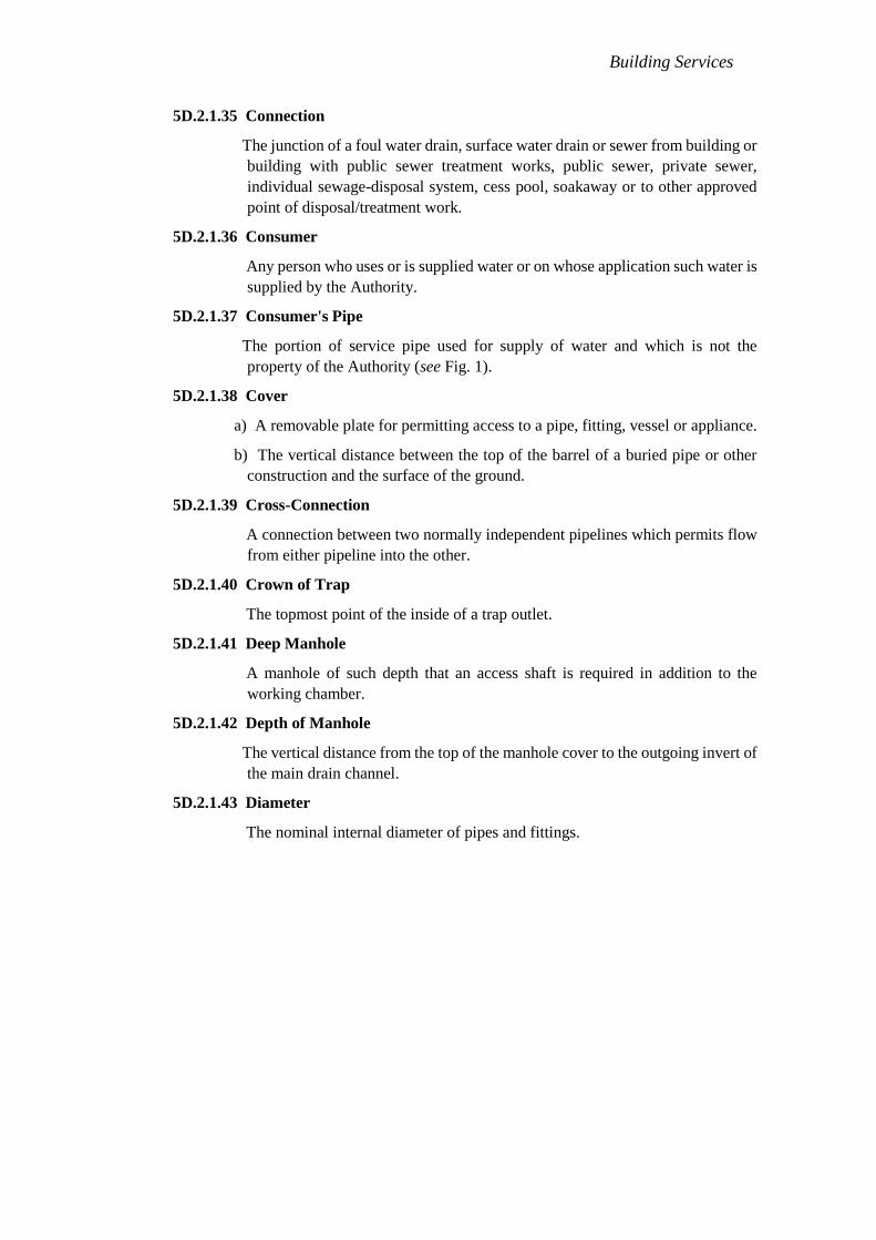
5D.2.1.35 Connection
The junction of a foul water drain, surface water drain or sewer from building or
building with public sewer treatment works, public sewer, private sewer,
individual sewage-disposal system, cess pool, soakaway or to other approved
point of disposal/treatment work.
5D.2.1.36 Consumer
Any person who uses or is supplied water or on whose application such water is
supplied by the Authority.
5D.2.1.37 Consumer's Pipe
The portion of service pipe used for supply of water and which is not the
property of the Authority (see Fig. 1).
5D.2.1.38 Cover
a) A removable plate for permitting access to a pipe, fitting, vessel or appliance.
b) The vertical distance between the top of the barrel of a buried pipe or other
construction and the surface of the ground.
5D.2.1.39 Cross-Connection
A connection between two normally independent pipelines which permits flow
from either pipeline into the other.
5D.2.1.40 Crown of Trap
The topmost point of the inside of a trap outlet.
5D.2.1.41 Deep Manhole
A manhole of such depth that an access shaft is required in addition to the
working chamber.
5D.2.1.42 Depth of Manhole
The vertical distance from the top of the manhole cover to the outgoing invert of
the main drain channel.
5D.2.1.43 Diameter
The nominal internal diameter of pipes and fittings.

Building Services
NOTE – The illustration is not intended to indicate recommended positions of
underground storage tank (where provided), pipes, etc and this will depend on
local situations.
FIG. 1 TYPICAL SKETCH FOR IDENTIFICATION OF DIFFERENT TYPES OF
WATER SUPPLY PIPES
5D.2.1.44 Direct Tap
A tap which is connected to a supply pipe and is subject to pressure from the
water main.
5D.2.1.45 Down take Tap
A tap connected to a system of piping not subject to water pressure from the
water main.
5D.2.1.46 Drain
A conduit, channel or pipe for the carriage of storm water, sewage, waste water
or other water-borne wastes in a building drainage system.
5D.2.1.47 Drain Ventilating Pipe (DVP)
A pipe installed to provide flow of air to or from a drain to prevent undue
concentration of foul air in the drain. The main soil pipe or main waste pipe
may serve as drain ventilating pipe wherever their upper portions, which do not
receive discharges, are extended to the roof level and let open to air.
5D.2.1.48 Drainage
The removal of any liquid by a system constructed for the purpose.
5D.2.1.49 Drainage Work
The design and construction of a system of drainage.
5D.2.1.50 Drop Connection
A length of conduit installed vertically immediately before its connection to a
sewer or to another drain.

Building Services
5D.2.1.51 Drop Manhole
A manhole installed in a sewer where the elevation of the incoming sewer
considerably exceeds that of the outgoing sewer; a vertical waterway outside
the manhole is provided to divert the waste from the upper to the lower level so
that it does not fall freely into the manhole except at peak rate of flow.
5D.2.1.52 Effective Opening
The minimum cross- sectional area at the point of water supply, measured or
expressed in terms of:
a) the diameter of a circle; and
b) the diameter of a circle of equivalent cross- sectional area, if the opening is not
circular.
5D.2.1.53 Feed Cistern
A storage vessel used for supplying cold water to a hot water apparatus,
cylinder or tanks.
5D.2.1.54 Fittings
Fittings shall mean coupling, flange, branch, bend, tees, elbows, unions, waste
with plug, P or S trap with vent, stop ferrule, stop tap, bib tap, pillar tap, globe
tap, ball valve, cistern storage tank, baths, water-closets, boiler, geyser,
pumping set with motor and accessories, meter, hydrant, valve and any other
article used in connection with water supply, drainage and sanitation.
5D.2.1.55 Fixture Unit
A quantity in terms of which the load producing effects on the plumbing system
of different kinds of plumbing fixtures is expressed on some arbitrarily chosen
scale.
5D.2.1.56 Fixture Unit Drainage
A measure of probable discharge into the drainage system by various types of
plumbing fixtures. The drainage fixture unit value for a particular fixture
depends on its volume rate of drainage discharge, on the time duration of a
single drainage operation and on the average time between successive
operations.
5D.2.1.57 Float Operated Valve
Ball valves or ball taps and equilibrium valves operated by means of a float.
5D.2.1.58 Flushing Cistern
A cistern provided with a device for rapidly discharging the contained water
and used in connection with a sanitary appliance for the purpose of cleaning the
appliance and carrying away its contents into a drain.
NOTE — The nominal size of a cistern is the quantity of water discharged per
flush.

Building Services
5D.2.1.59 Formation
The finished level of the excavation at the bottom of a trench or heading
prepared to receive the permanent work.
5D.2.1.60 French Drain or Rubble Drain
A shallow trench filled with coarse rubble, clinker, or similar material with or
without field drain pipes.
5D.2.1.61 Frost Line
The line joining the points of greatest depths below ground level up to which the
moisture in the soil freezes.
5D.2.1.62 General Washing Place
A washing place provided with necessary sanitary arrangement and common to
more than one tenement.
5D.2.1.63 Geyser
An apparatus for heating water with supply control on the inlet side and
delivering it from an outlet.
5D.2.1.64 Gully Chamber
The chamber built of masonry round a gully trap for housing the same.
5D.2.1.65 Gully Trap
A trap provided in a drainage system with a water seal fixed in a suitable
position to collect waste-water from the scullery, kitchen sink, wash basins,
baths and rain water pipes.
5D.2.1.66 Haunching
Outward sloping concrete support to the sides of a pipe or channel above the
concrete bedding.
5D.2.1.67 Heel Rest Bend or Duck-Foot Bend
A bend, having a foot formed integrally in its base, used to receive a vertical
pipe.
5D.2.1.68 High Altitudes
Elevations higher than 1 500 m above mean sea level (MSL).
5D.2.1.69 Highway Authority
The public body in which is vested, or which is the owner of, a highway
repairable by the inhabitants collectively; otherwise the body or persons
responsible for the upkeep of the highway.
5D.2.1.70 Horizontal Pipe
Any pipe of fitting which makes an angle of more than 45° with the vertical.
5D.2.1.71 Hot Water Tank
A vessel for storing hot water under pressure greater than atmospheric pressure.
Building Services
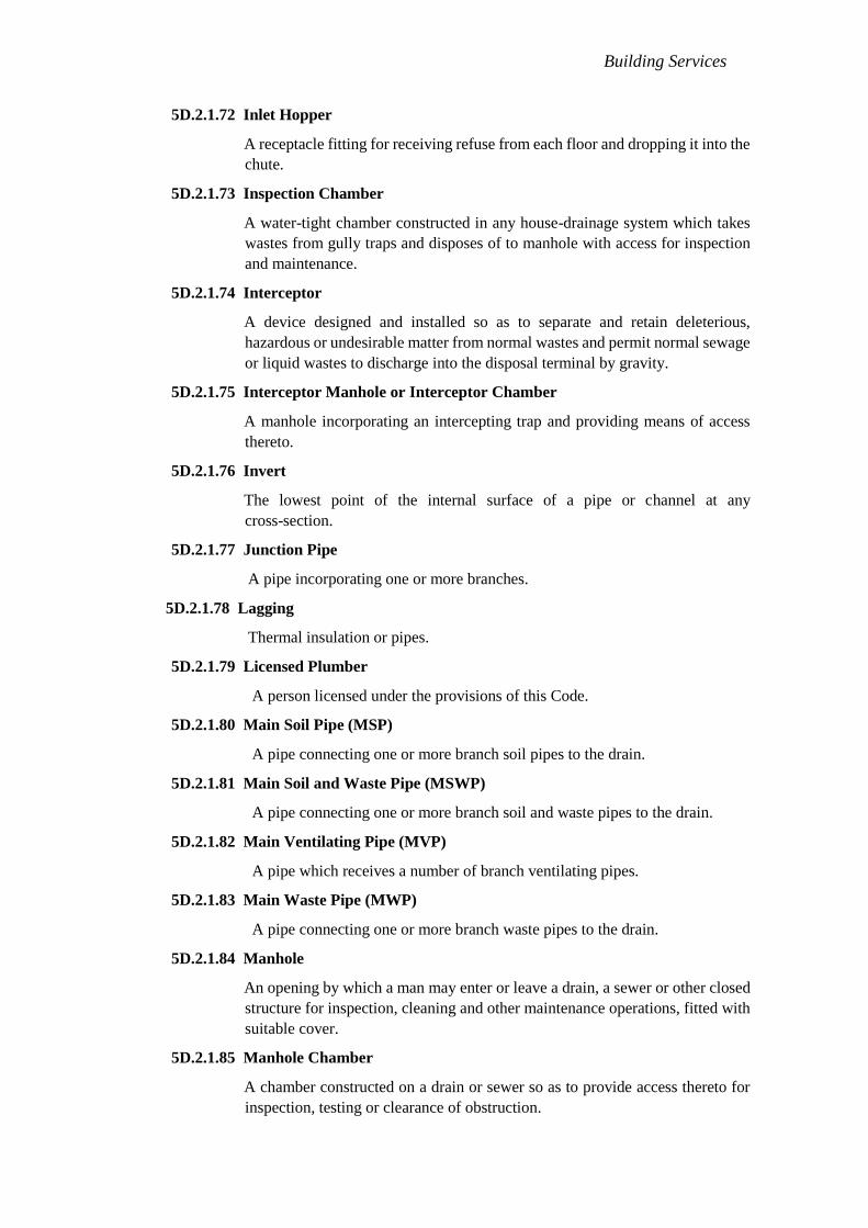
5D.2.1.72 Inlet Hopper
A receptacle fitting for receiving refuse from each floor and dropping it into the
chute.
5D.2.1.73 Inspection Chamber
A water-tight chamber constructed in any house-drainage system which takes
wastes from gully traps and disposes of to manhole with access for inspection
and maintenance.
5D.2.1.74 Interceptor
A device designed and installed so as to separate and retain deleterious,
hazardous or undesirable matter from normal wastes and permit normal sewage
or liquid wastes to discharge into the disposal terminal by gravity.
5D.2.1.75 Interceptor Manhole or Interceptor Chamber
A manhole incorporating an intercepting trap and providing means of access
thereto.
5D.2.1.76 Invert
The lowest point of the internal surface of a pipe or channel at any
cross-section.
5D.2.1.77 Junction Pipe
A pipe incorporating one or more branches.
5D.2.1.78 Lagging
Thermal insulation or pipes.
5D.2.1.79 Licensed Plumber
A person licensed under the provisions of this Code.
5D.2.1.80 Main Soil Pipe (MSP)
A pipe connecting one or more branch soil pipes to the drain.
5D.2.1.81 Main Soil and Waste Pipe (MSWP)
A pipe connecting one or more branch soil and waste pipes to the drain.
5D.2.1.82 Main Ventilating Pipe (MVP)
A pipe which receives a number of branch ventilating pipes.
5D.2.1.83 Main Waste Pipe (MWP)
A pipe connecting one or more branch waste pipes to the drain.
5D.2.1.84 Manhole
An opening by which a man may enter or leave a drain, a sewer or other closed
structure for inspection, cleaning and other maintenance operations, fitted with
suitable cover.
5D.2.1.85 Manhole Chamber
A chamber constructed on a drain or sewer so as to provide access thereto for
inspection, testing or clearance of obstruction.

Building Services
5D.2.1.86 Non-Service Latrine
Other than 'service latrine'.
5D.2.1.87 Offset
A pipe fitting used to connect two pipes whose axes are parallel but not in line.
5D.2.1.88 Period of Supply
The period of the day or night during which water supply is made available to
the consumer.
5D.2.1.89 Pipe System
The system to be adopted will depend on the type and planning of the building in
which it is to be installed and will be one of the following:
a) Single stack system (see Fig. 2) — The one- pipe system in which there is
no trap ventilation.
b) Single stack — Partially Vented — A via media between the one-pipe
system and the single stack system (see one-pipe system, partially
ventilated).
c) One-pipe system (see Fig. 3) — The system of plumbing in which the
wastes from the sinks, baths and wish basins, and the soil pipe branches are
all collected into one main pipe, which is connected, directly to the drainage
system. Gully traps and waste pipes are completely dispersed with, but all
the traps of the water closets, basins, etc, are completely ventilated to
preserve the water seal.
d) One-pipe system — Partially vented (also called single stack, partially
ventilated) — A system in which there is one soil pipe into which all water
closets, baths, sinks, and basins discharge. In addition, there is a relief
vent, which ventilates only the traps of water closets.
e) Two-pipe system (see Fig. 4) — The system of plumbing in which soil and
waste pipes are distinct and separate. The soil pipes being connected to the
FIG. 2 SINGLE STACK SYSTEM – MAIN FEATURE OF DESIGN

Building Services
drain direct and waste pipes through a trapped gully. All traps of all
appliances are completely ventilated in this system.
5D.2.1.90 Pipe Work
Any installation of piping with its fittings.
5D.2.1.91 Plumbing
a) The pipes, fixtures and other apparatus inside a building for bringing in the
water supply and removing the liquid and water borne wastes.
b) The installation of the foregoing pipes, fixtures and other apparatus.
5D.2.1.92 Plumbing System
The plumbing system shall include the water supply and distribution pipes;
plumbing fittings and traps; soil, waste, vent pipes and anti-siphonage pipes;
building drains and building sewers including their respective connections,
devices and appurtenances within the property lines of the premises; and
water-treating or water-using equipment.
5D.2.1.93 Potable Water
Water which is satisfactory for drinking, culinary and domestic purposes and
meets the requirements of the Authority.

Building Services
5D.2.1.94 Premises
Premises shall include passages, buildings and lands of any tenure, whether
open or enclosed, whether built on or not, and whether public or private in
respect of which a water rate or charge is payable to the Authority or for which
an application is made for supply of water.
5D.2.1.95 Puff Ventilation
The ventilation provided for waste traps in two-pipe system, in order to
preserve the water seal.
5D.2.1.96 Residual Head
The head available at any particular point in the distribution system.
5D.2.1.97 Saddle
A purpose made fitting, so shaped as to fit over a hole cut in a sewer or drain
used to form connections.
5D.2.1.98 Sanitary Appliances
The appliances for the collection and discharge of soil or waste matter.
5D.2.1.99 Service Latrine
A latrine from which the excreta are removed by manual agency and not by
water carriage.
5D.2.1.100 Service Pipe
Pipe that runs between the distribution main in the street and the riser in case of
a multi-storeyed building or the water meter in the case of an individual house
and is subject to water pressure from such main.
5D.2.1.101 Sewer
A pipe or conduit, generally closed, but normally not flowing full for carrying
sewage and/ or other waste liquids.

Building Services
5D.2.1.102 Slop Hopper (Slop Sink)
A hopper shaped sink, with a flushing run and outlet similar to those of a WC
pan, for the reception and discharge of human excreta.
5D.2.1.103 Soakaway
A pit, dug into permeable ground lined to form a covered perforated chamber or
filled with hard-core, to which liquid is led, and from which it may soak away
into the ground.
5D.2.1.104 Soffit (Crown)
The highest point of the internal surface of a sewer or culvert at any cross-
section.
5D.2.1.105 Soil Appliances
A sanitary appliance for the collection and discharge of excretory matter.
5D.2.1.106 Soil Pipe
A pipe that conveys the discharge of water closets or fixtures having similar
functions, with or without the discharges from other fixtures.
5D.2.1.107 Soil Waste
The discharge from water closets, urinals, slop hoper, stable yard or cowshed
gullies and similar appliances.
5D.2.1.108 Stop-Cock
A cock fitted in a pipe line for controlling the flow of water.
5D.2.1.109 Stop Tap
Stop tap includes stop-cock, stop valve or any other device for stopping the
flow of water in a line or system of pipes at will.
5D.2.1.110 Storage Tank
A container used for storage of water which is connected to the water main or
tube- well by means of supply pipe.
5D.2.1.111 Sub-Soil Water
Water occurring naturally in the sub-soil.
5D.2.1.112 Sub-Soil Water Drain
a) A drain intended to collect and carry away sub-soil water.
b) A drain intended to disperse into the sub-soil from a septic tank.
5D.2.1.113 Sub-Zero Temperature Regions
Regions where temperatures fall below 0°C and freezing conditions occur.
5D.2.1.114 Sullage
See 5D.2.1.129.
5D.2.1.115 Supply Pipe
So much of any service pipe as is not a communication pipe.

Building Services
5D.2.1.116 Supports
Hangers and anchors or devices for supporting and securing pipe and fittings to
walls, ceilings, floors or structural members.
5D.2.1.117 Surface Water
Natural water from the ground surface, paved areas and roofs.
5D.2.1.118 Surface Water Drain
A drain conveying surface water including storm water.
5D.2.1.119 Systems of Drainage
a) Combined system — A system in which foul water (sewage) and surface
water are conveyed by the same sewers and drains.
b) Separate system — A system in which foul water (sewage) and surface
water are conveyed by the separate sewers and drains.
c) Partially separate system — A modification of the separate system in which
part of the surface water is conveyed by the foul (sanitary) sewers and drains.
5D.2.1.120 Trade Effluent
Any liquid either with or without particles of matter in suspension which is
wholly or in part produced in the course of any trade or industry, at trade
premise. It includes farm wastes but does not include domestic sewage.
5D.2.1.121 Trap
A fittings or device so designed and constructed as to provide, when properly
vented, a liquid seal which will prevent the back passage of air without
materially affecting the flow of sewage or waste water through it.
5D.2.1.122 Vertical Pipe
Any pipe or fitting which is installed in a vertical position or which makes an
angle or not more than 45° with the vertical.
5D.2.1.123 Vent Slack/Vent Pipe
A vertical vent pipe installed primarily for the purpose of proving circulation of
air to and from any part of the drainage system. It also protects trap seals from
excessive pressure fluctuation.
5D.2.1.124 Vent System
A pipe or pipes installed to provide a flow of air to or from a drainage system or
to provide a circulation of air with in such system to protect traps seals from
siphonage and back-pressure.
5D.2.1.125 Warning Pipe
An overflow pipe so fixed that its outlet, whether inside or outside a building, is
in a conspicuous position where the discharge of any water therefrom can be
readily seen.

Building Services
5D.2.1.126 Wash-Out Valve
A device located at the bottom of the tank for the purpose of draining a tank for
cleaning, maintenance, etc.
5D.2.1.127 Waste Appliance
A sanitary appliance for the collection and discharge of water after use for
ablutionary, culinary and other domestic purpose.
5D.2.1.128 Waste Pipe
In plumbing, any pipe that receives the discharge of any fixtures, except water-
closets or similar fixtures and conveys the same to the house drain or soil or
waste stack. When such pipe does not connect directly with a house drain or
soil stack, it is called an indirect waste pipe.
5D.2.1.129 Waste-Water (Sullage)
The discharge from wash basins, sinks and similar appliances, which does not
contain human or animal excreta.
5D.2.1.130 Water Main (Street Main)
A pipe laid by the water undertakers for the purpose of giving a general supply
of water as distinct from a supply to individual consumers and includes any
apparatus used in connection with such a pipe.
5D.2.1.131 Water Outlet
A water outlet, as used in connection with the water distributing system, is the
discharge opening for the water (a) to a fitting; (b) to atmospheric pressure
(except into an open tank which is part of the water supply system); and (c) to
any water- operated device or equipment requiring water to operate.
5D.2.1.132 Water Seal
The water in a trap, which acts as a barrier to the passage of air through the trap.
5D.2.1.133 Water Supply System
Water supply system of a building or premises consists of the water service
pipe, the water distribution pipes, and the necessary connecting pipes, fittings,
control valves, and all appurtenances in or adjacent to the building or premises.
5D.2.1.134 Waterworks
Waterworks for public water supply include a lake, river, spring, well, pump
with or without motor and accessories, reservoir, cistern, tank, duct whether
covered or open, sluice, water main, pipe, culvert, engine and any machinery,
land, building or a thing used for storage, treatment and supply of water.
5D.2.1.135 Grey Water Reuse Systems
A system where grey water (wastewater but not soil or black water), is
collected, not treated and reused for acceptable purposes.
5D.2.1.136 Recycled Water
Water that has been treated and provided for reuse by a water distributor
through a reticulated water system.

Building Services
5D.2.1.137 Aquifer Recharge
The infiltration or injection of natural waters or recycled waters into an aquifer,
providing replenishment of the ground water resource.
5D.2.1.138 Aquifer Storage And Recovery
Injection of recycled water into aquifers for storage ,which may be recovered
later to meet water demands.
5D.2.1.139 Black Water
Toilet wastewater that contains organic matter from urine , faecal matter and
toilet paper.
5D.2.1.140 Direct Potable Recycling
The immediate addition of recycled water to the drinking water distribution
system ( without an intermediate stage of storage or mixing with surface or
ground water).
5D.2.1.141 Dual Reticulation
The simultaneous supply of water from two separate sources, requiring two sets
of pipes: one to provide potable water ( for drinking, cooking and bathing
purposes) ; the other to provide recycled water for non potable purposes.
5D.2.1.142 Effluent
Treated or untreated liquid waste flowing from agricultural and industrial
processes , or treated wastewater discharged from sewage treatment plants.
5D.2.1.143 Greywater
A combination of wastewater from the laundry , bathroom and kitchen . Kitchen
wastewater is usually not suitable for reuse.
5D.2.1.144 Grond Water
Subsurface water from which wells , springs or bores are fed.
5D.2.1.145 Indirect Potable Recycling
The withdrawal , treatment and distribution of potable (drinking) water from
surface or ground water that contains some proportation of recycled water.
Compare with ―direct potable recycling‖ , above.
5D.2.1.146 Industrial Purposes
Use of cycled water by industry for purposes including cooling processes ,
operation of boilers , manufacturing and processing activities , washdown and
cleaning , window washing , toilet and urinal flushing and other uses ( e.g. dust
suppression and irrigation of grounds)
5D.2.1.147 Internal Recycling
The use of recycled water by the entity that produced the wastewater irrigation .
The watering of crops ,pasture , golf courses ,parks , gardens and open spaces
,which may involve using different applications (e.g. drip ,trickle, spray and
flood).

Building Services
5D.2.1.148 Municipal Effluent
Used water from community and industry that enters the sewerage system.
5D.2.1.149 Non – Potable Purposes
The use of water for purposes other than drinking ,cooking , bathing and
laundry : for example ,irrigation of gardens ,lawns and toilet flushing.
5D.2.1.150 Potable
(Water) of a quality suitable for drinking ,cooking and personal bathing.
5D.2.1.151 Rainwater tanks
Tanks used to collect and store rainfall from household roofs for beneficial use
5D.2.1.152 Raw Water
Water that forms the source supply for potable water ,before it has been treated .
5D.2.1.153 Recycled Water
Appropriately treated effluent and urban storm water suitable for further use .
5D.2.1.154 Sewage
The used water of community or industry , conveyed through sewers to be
treated at a sewage treatment plant.
5D.2.1.155 Storm Water
All surface water runoff from rainfall , predominantly in urban catchments ;
such areas may include rural residential zones.
5D.2.1.156 Wastewater
The used water of community , industry or agriculture.
5D.2.1.157 Water Quality
The chemical , physical and biological condition of water.
5D.2.1.158 Water Recycling
Use of appropriately treated wastewater and urban stormwater for beneficial
purposes.
5D.2.1.159 Water Resource
The sources of supply of ground and surface water in a given area.
5D.3 GENERAL
5D.3.1 Basic Principles
5D.3.1.1 Potable Water
All premises intended for human habitation, occupancy, or use shall be
provided with supply of potable water. This water supply shall not be connected
with unsafe water resources, nor shall it be subject to the hazards of backflow.

Building Services
5D.3.1.2 Water Provision
Plumbing fixtures, devices and appurtenances shall be provided with water in
sufficient volume and at pressures adequate to enable them to function properly
and without undue noise under normal conditions of use.
There should be at least a residual head of 6 ft at the consumer's tap.
NOTE — The residual head shall be taken at the highest/farthest outlets in the
building.
5D.3.1.3 Water Conservation
Plumbing system shall be designed, installed and adjusted to use the optimum
quantity of water consistent with proper performance and cleaning.
5D.3.1.4 Safety Devices
Plumbing system shall be designed and installed with safety devices to
safeguard against dangers from contamination, explosion, overheating, etc.
5D.3.1.5 Plumbing Fixtures
It is recommended that each family dwelling unit should have at least one water
closet, one lavatory, one kitchen wash place or a sink, and one bathing wash
place or shower to meet the basic requirements of sanitation and personal
hygiene.
5D.3.1.6 Drainage System
The drainage system shall be designed, installed and maintained to guard against
fouling, deposit of solids and clogging and with adequate cleanouts so arranged
that the pipes may be readily cleaned.
5D.3.1.7 Materials and Workmanship
The plumbing system shall have durable material, free from defective
workmanship and so designed and installed as to give satisfactory service for its
reasonable expected life.
5D.3.1.8 Fixture Traps and Vent Pipes
Each fixture directly connected to the drainage system shall be equipped with a
liquid seal trap. Trap seals shall be maintained to prevent sewer gas, other
potentially dangerous or noxious fumes, or vemin from entering the building.
Further, the drainage system shall be designed to provide an adequate
circulation of air in all pipes with no danger of siphonage, aspiration, or forcing
of trap seals under conditions of ordinary use by providing vent pipes
throughout the system.
5D.3.1.9 Foul Air Exhaust
Each vent terminal shall extend to the outer air and be so installed as to minimize
the possibilities of clogging and the return of foul air to the building, as it
conveys potentially noxious or explosive gases to the outside atmosphere. All
vent pipes shall be provided with a cowl.

Building Services
5D.3.1.10 Testing
The plumbing system shall be subjected to required tests to effectively disclose
all leaks and defects in the work or the material.
5D.3.1.11 Exclusion from Plumbing System
No substance that will clog or accentuate clogging of pipes, produce explosive
mixtures, destroy the pipes or their joints, or interfere unduly with the
sewage-disposal process shall be allowed to enter the drainage system.
5D.3.1.12 Light and Ventilation
Wherever water closet or similar fixture shall be located in a room or
compartment, it should be properly lighted and ventilated.
5D.3.1.13 Individual Sewage Disposal Systems
If water closets or other plumbing fixtures are installed in buildings where
connection to public sewer is not possible, suitable provision shall be made for
acceptable treatment and disposal.
5D.3.1.14 Maintenance
Plumbing systems shall be maintained in a safe and serviceable condition.
5D.3.1.15 Accessibility
All plumbing fixtures shall be so installed with regard to spacing as to be
accessible for their intended use and for cleaning. All doors, windows and any
other device needing access within the toilet shall be so located that they have
proper access.
5D.3.1.16 Fixture for Disabled
Special toilet fixtures shall be provided for the disabled with required fixtures
and devices.
5D.3.1.17 Structural Safety
Plumbing system shall be installed with due regard to preservation of the
structural members and prevention of damage to walls and other surfaces.
5D.3.1.18 Protection of Ground and Surface Water
Sewage or other waste shall not be discharged into surface or sub-surface water
without acceptable form of treatment.
5D.3.2 Water Supply Connection
5D.3.2.1 Application for Obtaining Supply Connection
Every consumer, requiring a new supply of water or any extension or alteration
to the existing supply shall apply in writing in the prescribed form (see Annex
A) to the Authority.
5D.3.2.2 Bulk Supply
In the case of large housing colonies or where new services are so situated that it
will be necessary for the Authority to lay new mains or extend an existing main,
Building Services
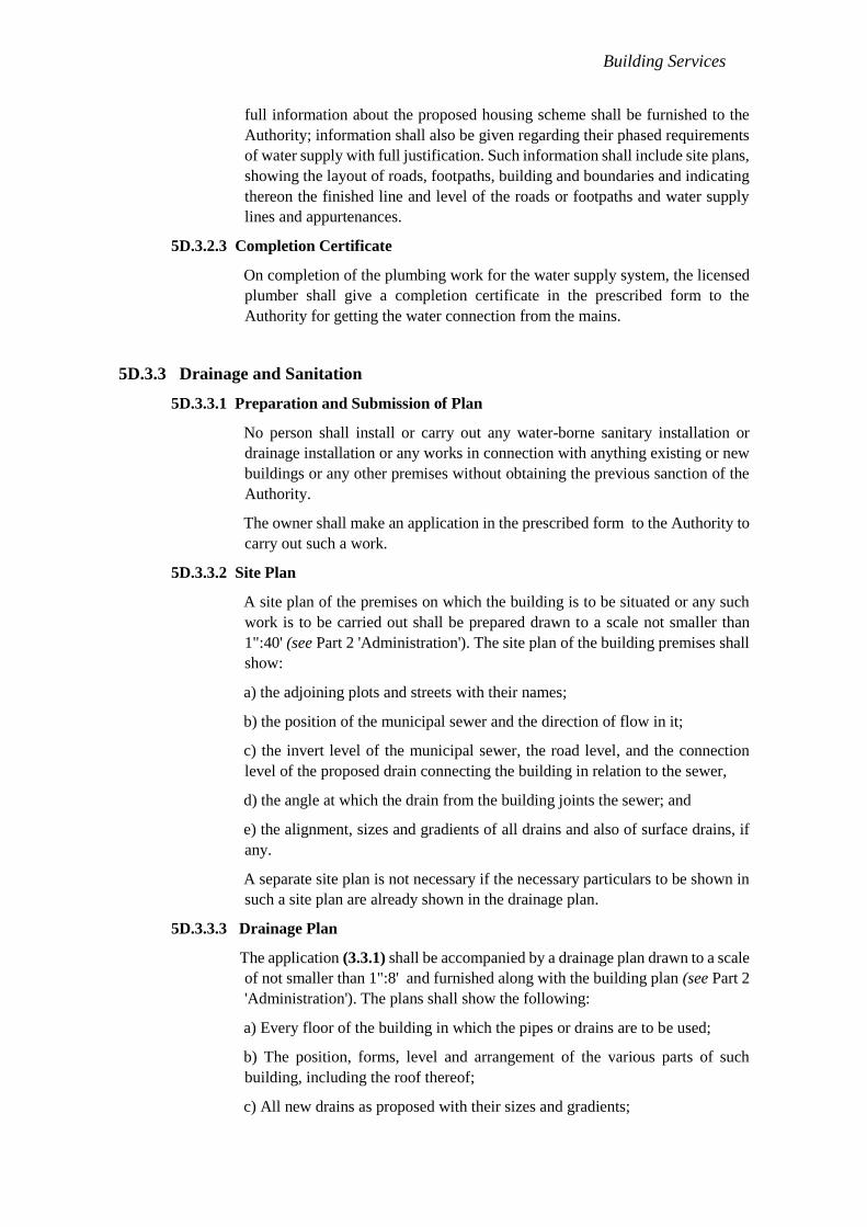
full information about the proposed housing scheme shall be furnished to the
Authority; information shall also be given regarding their phased requirements
of water supply with full justification. Such information shall include site plans,
showing the layout of roads, footpaths, building and boundaries and indicating
thereon the finished line and level of the roads or footpaths and water supply
lines and appurtenances.
5D.3.2.3 Completion Certificate
On completion of the plumbing work for the water supply system, the licensed
plumber shall give a completion certificate in the prescribed form to the
Authority for getting the water connection from the mains.
5D.3.3 Drainage and Sanitation
5D.3.3.1 Preparation and Submission of Plan
No person shall install or carry out any water-borne sanitary installation or
drainage installation or any works in connection with anything existing or new
buildings or any other premises without obtaining the previous sanction of the
Authority.
The owner shall make an application in the prescribed form to the Authority to
carry out such a work.
5D.3.3.2 Site Plan
A site plan of the premises on which the building is to be situated or any such
work is to be carried out shall be prepared drawn to a scale not smaller than
1":40' (see Part 2 'Administration'). The site plan of the building premises shall
show:
a) the adjoining plots and streets with their names;
b) the position of the municipal sewer and the direction of flow in it;
c) the invert level of the municipal sewer, the road level, and the connection
level of the proposed drain connecting the building in relation to the sewer,
d) the angle at which the drain from the building joints the sewer; and
e) the alignment, sizes and gradients of all drains and also of surface drains, if
any.
A separate site plan is not necessary if the necessary particulars to be shown in
such a site plan are already shown in the drainage plan.
5D.3.3.3 Drainage Plan
The application (3.3.1) shall be accompanied by a drainage plan drawn to a scale
of not smaller than 1":8' and furnished along with the building plan (see Part 2
'Administration'). The plans shall show the following:
a) Every floor of the building in which the pipes or drains are to be used;
b) The position, forms, level and arrangement of the various parts of such
building, including the roof thereof;
c) All new drains as proposed with their sizes and gradients;

Building Services
d) Invert levels of the proposed drains with corresponding ground levels;
e) The position of every manhole, gully, soil and waste pipe, ventilating pipe,
rain water pipe, water-closet, urinal, latrine, bath, lavatory, sink, trap or other
appliances in the premises proposed to be connected to any drain and the
following colours are recommended for indicating sewers, waste water pipes,
rainwater pipes an existing work.
Description of Work Colour
Sewers Red
Waste water pipes and rain-water pipes Blue
Existing work Black
f) The position of refuse chute, inlet hopper and collection chamber.
5D.3.3.3.1
In the case of an alteration or addition to an existing building, this clause shall
be deemed to be satisfied if the plans as furnished convey sufficient information
for the proposals to be readily identified with previous sanctioned plans and
provided the locations of tanks and other fittings are consistent with the
structural safety of the building.
5D.3.3.3.2
The plans for the building drainage shall in every case be accompanied by
specifications for the various items of work involved. This information shall be
supplied in the prescribed from.
5D.3.3.4
In respect of open drains, cross-sectional details shall be prepared to a scale not
smaller than 1":4' showing the ground and invert levels and any arrangement
already existing or proposed for the inclusion of any or exclusion of all storm
water from the sewers.
5D.3.3.5 Completion Certificate
At the completion of the plumbing installation work, the licensed plumber shall
give a completion certificate in the prescribed form.
5D.3.4 Licensing/Registration of Plumbers
5D.3.4.1 Execution of Work
The work which is required to be carried out under the provisions of this
Section, shall be executed only by a licensed plumber under the control of the
Authority and shall be responsible to carry out all lawful directions given by the
Authority. No individual shall engage in the business of plumbing unless so
licensed under the provisions of this Section.

Building Services
5D.3.4.1.1
No individual, firm, partnership or corporation shall engage in the business of
installing, repairing or altering plumbing unless the plumbing work performed
in the course of such business is under the direct supervision of a licensed
plumber and who has been assigned duties by authority.
5D.3.4.2 Examination and Certification
The Authority shall establish standards and procedure for the qualification,
examination and licensing of plumbers and shall issue licenses to such persons
who meet the qualifications thereof and successfully pass the examination.
5D.3.4.3
For guidelines for registration of plumbers including the minimum standards
for qualifications for the grant of licenses, reference may be made to Authority
concerned .
5D.4 WATER SUPPLY
5D.4.1 Water Supply Requirements for Buildings
5D.4.1.1 Water Supply for Residences
A minimum of 15gal to 22gallons per capita per day (gpcd) may be considered
adequate for domestic needs of urban communities, apart from non-domestic
needs as flushing requirements. As a general rule the following rates per capita
per day may be considered minimum for domestic and non-domestic needs:
a) For communities with population up to 20 000 and without flushing
system:
1) water supply through stand post 9 gpcd ,
Min 2) water supply through house service connection
15 to 20 gpcd
b) For communities with population 20 000 to100 000 20 to 30
gpcd
together with full flushing system
c) For communities with population above 100 000 30 to 40
gpcd
together with full flushing system
NOTE — The value of water supply given as 30 to 40 gallons per capita per day
may be reduced to 30 gallons per capita per day for houses for Lower Income
Groups (LIG) and Economically Weaker Section of Society (EWS), depending
upon prevailing conditions.
5D.4.1.1.1 Out of the 30 to 40 gallons per capita per day, 10 gallons per capita per day
may be taken for flushing requirements and the remaining quantity for other
domestic purposes. For estimating purpose regardless of community
population, water requirement may be assumed 40 gallons per capita per day.
Building Services
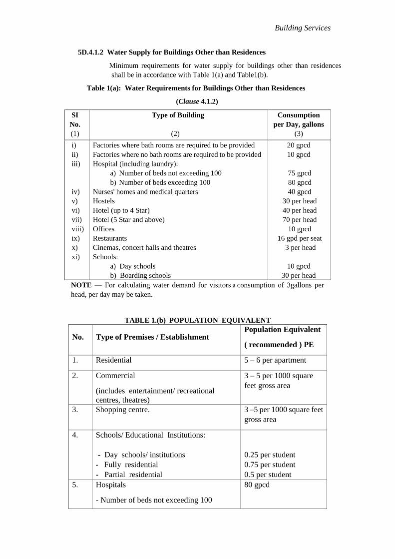
5D.4.1.2 Water Supply for Buildings Other than Residences
Minimum requirements for water supply for buildings other than residences
shall be in accordance with Table 1(a) and Table1(b).
Table 1(a): Water Requirements for Buildings Other than Residences
(Clause 4.1.2)
SI
No.
(1)
Type of Building
(2)
Consumption
per Day, gallons
(3)
i)
ii)
iii)
iv)
v)
vi)
vii)
viii)
ix)
x)
xi)
Factories where bath rooms are required to be provided
Factories where no bath rooms are required to be provided
Hospital (including laundry):
a) Number of beds not exceeding 100
b) Number of beds exceeding 100
Nurses' homes and medical quarters
Hostels
Hotel (up to 4 Star)
Hotel (5 Star and above)
Offices
Restaurants
Cinemas, concert halls and theatres
Schools:
a) Day schools
b) Boarding schools
20 gpcd
10 gpcd
75 gpcd
80 gpcd
40 gpcd
30 per head
40 per head
70 per head
10 gpcd
16 gpd per seat
3 per head
10 gpcd
30 per head
NOTE — For calculating water demand for visitors a consumption of 3gallons per
head, per day may be taken.
TABLE 1.(b) POPULATION EQUIVALENT
No. Type of Premises / Establishment Population Equivalent
( recommended ) PE
1. Residential 5 – 6 per apartment
2. Commercial
(includes entertainment/ recreational
centres, theatres)
3 – 5 per 1000 square
feet gross area
3. Shopping centre. 3 –5 per 1000 square feet
gross area
4. Schools/ Educational Institutions:
- Day schools/ institutions
- Fully residential
- Partial residential
0.25 per student
0.75 per student
0.5 per student
5. Hospitals
- Number of beds not exceeding 100
80 gpcd

Building Services
5D.4.1.3 Water Supply Requirements of Traffic Terminal Stations
The water supply requirements of traffic terminal stations (railway stations, bus
stations, harbours, airports, etc) include provisions for waiting rooms and
waiting halls. They do not, however, include requirements for retiring rooms.
Requirements of water supply for traffic terminal stations shall be according to
Table 2.
- Number of beds exceeding 100 2.0 per bed
2.5 per bed
6.
Clinic 0.5 per patient
7.
Hotels ( with dining and laundry facilities )
Hotels ( without dining and laundry )
4 per room
2.0 per room
8.
Market ( wet type ) 5 – 7 per 1000 square
feet gross area
9.
Market ( dry type ) 3 – 5 per 1000 square
feet gross area
10.
Beauty saloon
0.5 per client
11. Restaurants, cafeteria 0.4 per seat
12. Office 0.25
13. (i)Factories where bath rooms are required
to be provided
(ii) Factories where no bath rooms are
required
to be provided
0.5
0.25
14. Nurses' homes and medical quarters 1
Note:
1 PE is equivalent to 40 gallons per capita per day ( gpcd )
30 % of water supply is generally taken as soil water.

Building Services
Table 2: Water Supply Requirements for Traffic Terminal Stations
(Clause 4.1.3)
SI
No. Nature of Station/Terminal
Where Bathing
Facilities are Provided
gallons/capita
Where Bathing
Facilities are not
Provided gallons/capita
(1) (2) (3) (4)
i) Intermediate stations
(excluding mail and express stops)
10 5
ii) Junction stations and intermediate
stations where mail or express
stoppage is provided
15 10
iii) Terminal stations 10 10
iv) International and domestic airports 15 15
NOTES
1 The number of persons shall be determined by average number of passengers
handled by the station daily; due consideration may be given to the staff and
vendors likely to use facilities.
2 Consideration should be given for seasonal average peak requirements.
5D.4.1.4 Water Supply for Fire Fighting Purposes
5D.4.1.4.1 The Authority shall make provision to meet the water supply requirements for
fire fighting in the city/area, depending on the population density and types of
occupancy.
5D.4.1.4.2 Provision shall be made by the owner of the building for water supply
requirements for fire fighting purposes within the building, depending upon
the height and occupancy of the building, in conformity with the requirements
laid down in Part 4 'Fire and Life Safety'.
5D.4.1.4.3 The requirements regarding water supply in storage tanks, capacity of fire
pumps, arrangements of wet riser-cum-down comer and wet riser installations
for buildings above 50ft in height, depending upon the occupancy use, shall be
in accordance with Part 4 'Fire and Life Safety'.
5D.4.1.5 Water Supply for Other Purposes
5D.4.1.5.1 Water supply in many buildings is also required for many other applications
other than domestic use, which must be identified in the initial stages of
planning so as to provide the requisite water quantity, storage capacity and
pressure as required for each application. In such instances information about
the water use and the quality required may be obtained from the users. Some
typical uses other than domestic use and fire fighting purposes are air
conditioning and air washing, swimming pools and water bodies and gardening.
Building Services
5D.4.2 Water Sources and Quality
5D.4.2.1 Sources of Water
The origin of all sources of water is rainfall. Water can be collected as it falls as
rain before it reaches the ground; or as surface water when it flows over the
ground or is pooled in lakes or ponds; or as ground water when it percolates into
the ground and flows or collects as ground water; or from the sea into which it
finally flows.
5D.4.2.2 The quality of water to be used for drinking shall follow WHO GIUDELINES .
5D.4.2.3 For purposes other than drinking, water if supplied separately, shall be absolutely
safe from bacteriological contamination so as to ensure that there is no danger to
the health of the users due to such contaminants.
5D.4.2.4 Waste Water Reclamation
Treated sewage or other waste water of the community may be utilized for
non-domestic purposes such as water for cooling, flushing, lawns, parks, fire
fighting and for certain industrial purposes after giving the necessary treatment
to suit the nature of the use. This supply system shall be allowed in residences
only if proper provision is made to avoid any cross connection of this treated
waste water with domestic water supply system.
5D.4.2.5 Whenever a building is used after long intervals, the water quality of the stored
water must be checked so as to ensure that the water is safe for use as per water
quality requirements specified in this Code.
5D.4.3 Estimate of Demand Load
5D.4.3.1 Estimates of total water supply requirements for buildings shall be based on the
occupant load consistent with the provisions of 4.1.
5D.4.3.1.1 For residential buildings, the requirements of water shall be based on the actual
number of occupants; where this information is not available, the number of
occupants for each residential unit may be based on a family of five to six. For
assessing the population in other occupants, reference may be made to Part 4
'Fire and Life Safety'.
5D.4.3.1.2 In making assessment of water supply requirements of large complexes, the
future occupant load shall be kept in view. Use may be made of the following
methods for estimating future requirements:
a) demographic method of population projection,
b) arithmetic progression method,
c) geometrical progression method,
d) method of varying increment or incremental increase,
e) logistic method,
f) graphical projection method, and
g) graphical comparison method.

Building Services
5D.4.4 Storage of Water
5D.4.4.1 In a building, provision is required to be made for storage of water for the
following reasons:
a) to provide against interruptions of the supply caused by repairs to mains, etc;
b) to reduce the maximum rate of demand on the mains;
c) to tide over periods of intermittent supply; and
d) to maintain a storage for the fire fighting requirement of the building (see
Part 4 'Fire and Life Safety').
5D.4.4.2 The water may be stored either in overhead tanks (OHT) and/or underground
tanks (UGT).
5D.4.4.3 Materials Used
Reservoirs and tanks for the reception and storage of water shall be constructed
of reinforced concrete brick masonry, ferro cement precast, mild steel, stainless
steel, galvanized iron or plastic.
5D.4.4.3.1 Tanks made of steel may be of welded, riveted or pressed construction. The
metal shall be galvanized coated externally with a good quality anti-corrosive
weather-resisting paint. Lead-based paint shall not be used in the tank.
Lead-lined tanks shall not be used. Rectangular pressed steel tanks shall
conform to good practice [9-1(3)].
5D.4.4.4 Each tank shall be provided with the following:
a) Manholes — Adequate number of manholes for access and repair. The
manholes shall be made of corrosion resistant material (for example, cast iron,
reinforced cement concrete, steel fibre reinforced concrete, galvanized steel,
high density polyethylene, fibre glass reinforced plastic or such other materials
acceptable to the Authority). Manholes shall be provided with locking
arrangement to avoid misuse and tampering.
b) Catch Rings and Ladders — Tanks higher than 3 feet deep shall be provided
with corrosion resistant catch rings, steps or ladders according to the depth to
enable a person to reach the bottom of the tank.
c) Overflow Pipe — Each tank shall be provided with an overflow pipe
terminating above the ground/terrace level to act as a 'Warning Pipe' to indicate
overflow conditions. The size of the overflow pipe shall be adequate to accept
the flow. Normally the overflow pipe size shall be one size higher than the inlet
pipe. When the inlet pipe diameter is large, two or more overflow pipes of
equivalent cross- section may be provided.
d) Vent Pipes — Tanks larger than 1200 gallons capacity shall be provided with
vent pipes to prevent development pressure in the tank which might result in
NO FLOW condition or inward collapse of the tank.
Scour Pipe — Each tank shall be provided with a scour pipe with an accessible
valve for emptying the tank.
e) Connection of Overflow and Scour Pipe — Under no circumstances tank
overflow and scour pipe shall be connected to any drain, gully trap or manhole

Building Services
to prevent back flow and contamination of the water. All such connections shall
be discharged over a grating with an air gap of 2 inches. All overflow and vent
pipes shall be provided with a mosquito proof brass grating to prevent ingress
of mosquito, vermin and other insects.
f) The top slab of the tank must be suitably sloped away from its centre for proper
drainage of the rainwater.
g) Tanks on terraces and above ground shall be supported by appropriate
structural members so as to transfer the load of the tank and the water directly
on the structural members of the building.
5D.4.4.5 Every storage tank shall be easily accessible and placed in such a position as to
enable thorough inspection and cleaning to be carried out. If the storage capacity
required is more than 1200 gallons, it is advantageous to arrange it in a series of
tanks so interconnected that each tank can be isolated for cleaning and inspection
without interfering with the supply of water. In large storage tanks, the outlet
shall be at the end opposite the inlet to avoid stagnation of the water.
5D.4.4.6 The outlet pipe shall be fixed 2 inches to 3 inches above the bottom of the tank and
fitted with a strainer, preferably of brass.
5D.4.4.7 In the case of underground storage tanks, the design of the tank shall be such as to
provide for the draining of the tank when necessary and water shall not be allowed
to collect around the tank. The tank shall be perfectly water-proof and shall be
provided with a cement concrete cover, having a manhole opening, with a properly
fitting hinged cast iron cover on a leak-proof cast iron frame.
The underground tanks should not be located in low lying areas or near any public
or private sewer, septic tank, leaching pool or soakage pit to prevent any
contamination. The overflow of the tank should be well above (preferably 2 feet)
the external surface level and terminate as a warning pipe with a mosquito proof
grating. Care must be taken to prevent backflow of local surface water into the tank
in case of local flooding. Otherwise the overflow must be terminated in a more
safer manner as per the site conditions. For tanks with at least one side exposed to a
basement, it is safer to discharge the overflow into the basement level.
The tank top slab shall also be designed to carry the load due to fire tender
movement where anticipated as in the case of an extended basement.
There should be no common wall between the tanks storing safe water and tanks
storing water from unsafe sources.
In the case of storage tanks built under the floor slab, it must have at least 2 feet
space around the perimeter of the tank to enable regular inspection and
maintenance. It must have at least 3 feet vertical space between the floor slab and
cover slab of the tank to enable regular inspection and maintenance.
5D.4.4.8 In case of overhead tanks, bottom of the tanks shall be placed clear off the terrace
slab such that the elevation difference between the outlet pipe of the tank and the
highest fixture at the top floor of the building is minimum 6 feet, which shall also
prevent leakage into the structural slab. In tall buildings, the top of the tank shall be
provided with the safe ladder or staircase. The top slab shall be provided with
railing or a parapet wall.

Building Services
5D.4.4.9 For jointing steel pipe to a storage tank, the end of the pipe shall be screwed,
passed through a hole in the tank and secured by backnuts, both inside and outside.
The pipe end shall be flush with the face of the inside backnut. For jointing copper
pipe to steel or copper tank, a connector of non-ferrous material shall be used. The
connector shall have a shoulder to bear on the outside of the tank and shall be
secured by a backnut inside.
5D.4.4.10 The quantity of water to be stored shall be calculated taking into account the
following factors:
a) hours of supply at sufficiently high pressure to fill up the overhead storage
tanks;
b) frequency of replenishment of overhead tanks, during the 24 h;
c) rate and regularity of supply; and
d) consequences of exhausting storage particularly in case of public buildings like
hospitals.
If the water supply is intermittent and the hours of supply are irregular, it is
desirable to have a minimum storage of half a day's supply for overhead tanks.
For additional requirement of water storage for firefighting purposes, reference
may be made to Part 4 'Fire and Life Safety'.
NOTE — General guidelines for calculation of capacity of these storage tanks are
as follows:
a) In case only OHT is provided, it may be taken as minimum one day's
requirement;
b) In case only UGT is provided, it may be taken as minimum 150 percent of one
day's requirement; and
c) In case combined storage is provided, it may be taken as minimum 100 percent
UGT and minimum 50 percent OHT of one day's requirement.
5D.4.4.11 When only one communication pipe is provided for water supply to a building, it
is not necessary to have separate storage for flushing and sanitary purposes for
health reasons. In such cases when only one storage tank has been provided,
tapping of water may be done at two different levels (the lower tapping for
flushing) so that a part of the water will be exclusively available for flushing
purposes.
5D.4.5 Materials, Fittings and Appliances
5D.4.5.1 Standards for Materials, Fittings and Appliances
All materials, water fittings and appliances shall conform to Part 5 'Building
Materials'.
5D.4.5.2 Materials for Pipes
Pipes may be of any of the following materials:
a) cast iron, vertically cast or centrifugally (spun) cast,
b) steel (internally lined or coated with bitumen or a bituminous composition, and
out-coated with cement concrete or mortar, where necessary),

Building Services
c) reinforced concrete,
d) prestressed concrete,
e) galvanized mild steel tubes,
f) copper,
g) brass,
h) wrought iron,
i) asbestos cement,
j) polyethylene,
k) unplasticized PVC,
l) chlorinated PVC, or
m) stainless steel.
5D.4.5.2.1 The material chosen shall be resistant to corrosion, both inside and outside or
shall be suitably protected against corrosion.
5D.4.5.2.2 Polyethylene and unplasticized PVC pipes shall not be installed near hot water
pipes or near any other heat sources. For temperature limitations in the use of
polyethylene and unplasticized PVC pipes to convey water, reference may be
made to good practice [9-1(4)].
5D.4.6 Design of Distribution Systems
5D.4.6.1 General
All buildings shall conform to the general requirements given in 3.1.
5D.4.6.2 Rate of Flow
One of the important items that needs to be determined before the sizes of pipes
and fittings for any part of the water piping system may be decided upon, is the rate
of flow in the service pipe which, in turn depends upon the number of hours for
which the supply is available at sufficiently high pressure. If the number of hours
for which the supply is available is less, there will be large number of fittings in use
simultaneously and the rate of flow will be correspondingly large.
The data required for determining the size of the communication and service pipes
are:
a) the maximum rate of discharge required;
b) the length of the pipe; and
c) the head loss by friction in pipes, fittings and meters.
5D.4.6.3 Discharge Computation
5D.4.6.3.1 Design of consumer's pipes based on fixture units
The design of the consumers' pipes or the supply pipe to the fixtures is based
on:
a) the number and kind of fixtures installed;
b) the fixture unit flow rate; and

Building Services
c) the probable simultaneous use of these fixtures.
The rates at which water is desirably drawn into different types of fixtures
are known. These rates become whole numbers of small size when they are
expressed in fixture unit.
The fixture units for different sanitary appliances or groups of appliances
are given in Table 3 and Table 4.
Table 3: Fixture Unit for Different Types of Fixtures with Inlet Pipe Diameter
(CLAUSE 4.6.3.1)
SI
No.
Type of Fixture Fixture Unit FU
as Load Factor
Minimum Normal Size
of Fixture Branch, in
(1) (2) (3) (4)
i) Ablution tap 1 ½
ii) Bath tub supply by spout
Shower over tub does not add to the load
3 ½
iii) Shower stall domestic 2 ½
iv) Shower in groups per head 3 ½
v) Wash basin domestic use 1 ½
vi) Wash basin public use 2 ½
vii) Wash basin surgical 2 ½
viii) Scrub station in hospitals per outlet 3 ½
ix) Drinking water fountain/water cooler 0.5 ½
x) Water-closet with cistern (single/double flush) 1 ½
xi) Water-closet with flush or magic eye operated valve 8 1 / 1¼
xii) Urinals with auto flushing cisterns 4 ½ / ¾
xiii) Urinals with flush or magic eye operated valve 2 ½ / ¾
xiv) Kitchen sink (domestic use) 2 ½ / ¾
xv) Washing machine 3 ½ / ¾

Building Services
Table 4: Fixture Unit for Different Types of Fixtures Based on Pipe or Trap Diameter
(CLAUSE 4.6.3.1)
SI
No.
(1)
Drain or Trap Outlet
Diameter(inches)
(2)
Fixture Unit
(FU)
(3)
i) 1¼ or smaller 1
ii) 1½ 2
iii) 2 3
iv) 2½ 4
v) 3 5
vi) 4 6
NOTE — Before using the above figures check the actual flow from the outlets of special equipment,
for example, small period high discharges, for example, from washing machines, boiler blow downs,
filter backwash and water tank emptying operations.
Table 5: Probable Simultaneous Demand
(Clause 4.6.3.2)
No. of
Fixture
Units
(1)
System with Flush Tanks Demand
(Based on Fixture Units)
System with Valves Demand
(After Hunter)
Unit Rate Flow1) Flow in gallon per minute Unit Rate Flow1) Flow in gallon per minute
(2) (3) (4) (5)
20 2.0 12.45 4.7 29.28
40 3.3 20.55 6.3 39.25
60 4.3 26.80 7.4 46.09
80 5.1 31.77 8.3 51.70
100 5.7 35.51 9.1 56.69
120 6.4 39.86 9.8 61.05
140 7.1 44.22 10.4 64.79
160 7.6 47.34 11.0 68.53
180 8.2 51.08 11.6 72.27
200 8.6 53.57 12.3 76.63
220 9.2 57.31 12.7 79.11
240 9.6 59.80 13.1 84.60
300 11.4 71.02 14.7 91.56
400 14.0 87.21 17.0 105.91
500 16.7 104.04 19.0 118.36
600 19.4 120.85 21.1 131.45
700 21.4 133.32 23.0 143.29
800 24.1 150.13 24.5 152.61
900 26.1 162.58 26.1 162.58
1000 28.1 175.05 28.1 175.05
1500 36.1 224.88 36.1 224.88
2000 43.9 273.48 43.9 273.48
2500 51.1 318.32 51.1 318.32
3000 57.8 360.07 57.8 360.07
1)Unit rate of flow = Effective fixture units
Building Services
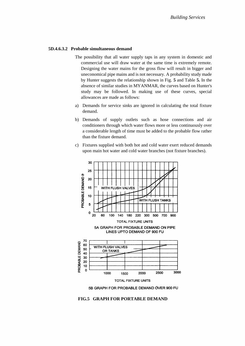
5D.4.6.3.2 Probable simultaneous demand
The possibility that all water supply taps in any system in domestic and
commercial use will draw water at the same time is extremely remote.
Designing the water mains for the gross flow will result in bigger and
uneconomical pipe mains and is not necessary. A probability study made
by Hunter suggests the relationship shown in Fig. 5 and Table 5. In the
absence of similar studies in MYANMAR, the curves based on Hunter's
study may be followed. In making use of these curves, special
allowances are made as follows:
a) Demands for service sinks are ignored in calculating the total fixture
demand.
b) Demands of supply outlets such as hose connections and air
conditioners through which water flows more or less continuously over
a considerable length of time must be added to the probable flow rather
than the fixture demand.
c) Fixtures supplied with both hot and cold water exert reduced demands
upon main hot water and cold water branches (not fixture branches).
FIG. 5 GRAPH FOR PORTABLE DEMAND
FIG.5 GRAPH FOR PORTABLE DEMAND

Building Services
5D.4.6.4 Pipe Size Computation
Commercially available standard sizes of pipes are only to be used against the
sizes arrived at by actual design. Therefore, several empirical formulae are
used, even though they give less accurate results. The Hazen and William's
formula and the charts based on the same may be used without any risk of
inaccuracy in view of the fact that the pipes normally to be used for water
supply are of smaller sizes. Nomogram of Hazen and William's equation has
been provided in Annex F.
5D.4.7 Distribution Systems in Multi-Storeyed Buildings
5D.4.7.1
There are four basic methods of distribution of water to multi-storeyed buildings.
a) Direct supply from mains to ablutionary taps and kitchen with WCs and urinals
supplied by overhead tanks.
b) Direct Pumping Systems
c) Hydro-Pneumatic Systems
d) Overhead Tanks Distribution
5D.4.7.2 Direct Supply System
This system is adopted when adequate pressure is available round the clock at
the topmost floor. With limited pressure available in most city mains, water
from direct supply is normally not available above two or three floors. For
details of this system, reference may be made to good practice [9-1(5)] may be
referred.
5D.4.7.3 Direct Pumping
5D.4.7.3.1 Water is pumped directly into the distribution system without the aid of any
overhead tank, except for flushing purposes. The pumps are controlled by a
pressure switch installed on the line. Normally a jockey pump of smaller
capacity installed which meets the demand of water during low consumption
and the main pump starts when the demand is greater. The start and stop
operations are accomplished by a set if pressure switches are installed directly
on the line. In some installation, a timer switch is installed to restrict the
operating cycle of the pump.
5D.4.7.3.2 Direct pumping systems are suitable for buildings where a certain amount of
constant use of water is always occurring. These buildings are all centrally air
conditioned buildings for which a constant make up supply for air conditioning
cooling towers is required.
5D.4.7.3.3 The system depends on a constant and reliable supply of power. Any failure in
the power system would result in a breakdown in the water supply system.
5D.4.7.3.4 The system eliminates the requirements of overhead tanks for domestic
purposes (except for flushing) and requires minimum space (see Fig. 6).

Building Services
5D.4.7.4 Hydro-Pneumatic Systems
5D.4.7.4.1 Hydro-pneumatic system is a variation of direct pumping system. An air-tight
pressure vessel is installed on the line to regulate the operation of the pumps.
The vessel capacity shall be based on the cut- in and cut-out pressure of the
pumping system depending upon allowable start/stops of the pumping system.
As pumps operate, the incoming water in the vessel, compresses the air on top.
When a predetermined pressure is reached in the vessel, a pressure switch
installed on the vessel switches off the pumps. As water is drawn into the
system, pressure falls into the vessel starting the pump at preset pressure. The
air in the pressure tank slowly reduces the volume due to dissolution in water
and leakages from pipe lines. An air compressor is also necessary to feed air
into the vessel so as to maintain the required air-water ratio. The system shall
have reliable power supply to avoid breakdown in the water supply.
5D.4.7.4.2 There is an alternate option of providing variable speed drive pumping system
where a pump with a large variation in its pressure-discharge and speed of the
pump is efficiently used to deliver water at rates of flow as required by the
system by changing its speed by a varying its with the assistance of an
electronic device which will reduce the rate of flow from speed of the motor
from 960 rpm to 3 000 rpm. With this arrangement the same pump is able to
deliver water as required at different times of the day. The system consumes
energy in proportion to the work done and save considerable amount of power
as compared to the fixed speed pumps used conventionally.
5D.4.7.4.3 Hydro-pneumatic system generally eliminates the need for an over head tank
and may supply water at a much higher pressure than available from overhead
tanks particularly on the upper floors, resulting in even distribution of water at
all floors (see Fig. 7).
FIG. 6 DIRECT PUMPING SYSTEM APPLICABLE WHERE THERE
IS CONTINUOUS DEMAND ON SYSTEM

Building Services
5D.4.7.5 Overhead Tank Distribution
5D.4.7.5.1 This is the most common of the distribution systems adopted by various type of
buildings.
5D.4.7.5.2 The system comprises pumping water to one or more overhead tanks placed at
the top most location of the hydraulic zone.
5D.4.7.5.3 Water collected in the overhead tank is distributed to the various parts of the
building by a set of pipes located generally on the terrace.
5D.4,7.5.4 Distribution is accomplished by providing down takes to various fixtures (see
Fig. 8).
5D.4.8 General Requirements for Pipe Work
5D.4.8.1 Mains
The following principles shall apply for the mains:
Service mains shall be of adequate size to give the required rate of flow.
FIG. 7 HYDRO – PNEUMATIC SYSTEM FIG. 8 OVERHEAD TANK
DISTRIBUTION
a) The mains shall be divided into sections by the provisions of sluice valves and
other valves so that water may be shut off for repairs.
b) To avoid dead ends, the mains shall be arranged in a grid formation or in a
network.
c) Where dead ends are unavoidable, a hydrant shall be provided to act as a
wash-out.
d) The wash-out valve shall not discharge directly into a drain or sewer, or into a
manhole or chamber directly connected to it; an effectively trapped chamber
shall be interposed, into which the wash-out shall discharge.
e) Air valves shall be provided at all summits, and wash-out at low points between
summits.

Building Services
f) Mains need not be laid at unvarying gradients, but may follow the general
contour of the ground. They shall, however, fall continuously towards the
wash-out and rise towards the air valves. The gradient shall be such that there
shall always be a positive pressure at every point under working conditions.
g) The cover for the mains shall be at least 3 feet under roadways and 2 feet 6
inches in the case of footpaths. This cover shall be measured from the top of the
pipe to the surface of the ground.
h) The mains shall be located sufficiently away from other service lines like
electric and telegraph cables to ensure safety and where the mains cannot be
located away from such lines, suitable protective measures shall be accorded to
the mains.
5D.4.8.2 Communication Pipes
a) Every premises that is supplied with water by the Authority shall have its own
separate communication pipe. In the case of a group or block of premises
belonging to the same owner the same communication pipe may supply water
to more than one premises with the prior permission of the Authority.
b) The communication pipe between the water main and the stop-cock at the
boundary of the premises shall be laid by the Authority.
c) Connections up to 2 inches diameter may be made on the water main by means
of screwed ferrules, provided the size of the connections does not exceed
one-third the size of the water main. In all other cases, the connection shall be
made by a T-branch off the water main.
d) As far as practicable, the communication pipe and the underground service
pipe shall be laid at right angles to the main and in approximately straight lines
to facilitate location for repairs. It is also recommended that the
communication pipe be laid in a pipe sleeve of larger dia. Made of
non-corrosive material to protect the communication pipe.
e) Every communication pipe shall have a stopcock and meter inserted in it. The
waterway of each such fitting shall not be less than the internal sectional area
of the communication pipe and the fittings shall be located within the premises
at a conspicuous place accessible to the Authority which shall have exclusive
control over it.
5D.4.8.3 Consumer Pipes
a) No consumer pipe shall be laid in the premises to connect the communication
pipe without the approval of the Authority.
b) The consumer pipe within the premises shall be laid underground with a
suitable cover to safeguard against damage from traffic and extremes of
weather.
c) To control the branch pipe to each separately occupied part of a building
supplied by a common service pipe, a stop tap shall be fixed to minimize the
interruption of the supply during repairs. All such stop valves shall be fixed in
accessible positions and properly protected. To supply water for drinking or
for culinary purposes, direct taps shall be provided on the branch pipes
Building Services
connected directly to the consumer pipe. In the case of multi-storeyed
buildings, downtake taps shall be supplied from overhead tanks.
d) Pumps shall not be allowed on the service pipe, as they cause a drop in
pressure on the suction side, thereby affecting the supply to the adjoining
properties. In cases where pumping is required, a properly protected storage
tank of adequate capacity shall be provided to feed the pump.
e) No direct boosting (by booster pumps) shall be allowed from the service pipes
(communication and consumer pipes).
f) Consumer pipes shall be so designed and constructed as to avoid air-locks.
Draining taps shall be provided at the lowest points from which the piping
shall rise continuously to draw-off taps.
g) Consumer pipes shall be so designed as to reduce the production and
transmission of noise as much as possible.
h) Consumer pipes in roof spaces and unventilated air spaces under floors or in
basements shall be protected against corrosion.
i) Consumer pipes shall be so located that they are not unduly exposed to
accidental damage and shall be fixed in such positions as to facilitate cleaning
and avoid accumulations of dirt.
j) All consumer pipes shall be so laid as to permit expansion and contraction or
other movements.
5D.4.8.4 Prohibited Connections
a) A service pipe shall not be connected into any distribution pipe; such
connection may permit the backflow of water from a cistern into the service
pipe, in certain circumstances, with consequent danger of contamination and
depletion of storage capacity. It might also result in pipes and fittings being
subjected to a pressure higher than that for which they are designed, and in
flooding from overflowing cisterns.
b) No pipe for conveyance or in connection with water supplied by the Authority
shall communicate with any other receptacle used or capable of being used for
conveyance other than water supplied by the Authority.
c) Where storage tanks are provided, no person shall connect or be permitted to
connect any service pipe with any distributing pipe.
d) No service or supply pipe shall be connected directly to any water-closet or a
urinal. All such supplies shall be from flushing cisterns which shall be supplied
from storage tank.
e) No service or supply pipe shall be connected directly to any hot water system
or to any other apparatus used for heating other than through a feed cistern
thereof.
5D.4.9 Jointing of Pipes
5D.4.9.1 Cast Iron Pipes
Jointing may be done by any of the following methods:
a) spigot and socket joints, or
Building Services
b) flanged joints in accordance with good practice [9-1(6)]. The lead shall
conform to the accepted standards [9-1(7)].
5D.4.9.2 Steel Pipes
Plain-ended steel pipes may be jointed by welding. Electrically welded steel pipes
shall be jointed in accordance with good practice [9-1(8)].
5D.4.9.3 Wrought Iron and Steel Screwed Pipes
Screwed wrought iron or steel piping may be jointed with screwed and socketed
joints. Care shall be taken to remove any burr from the end of the pipes after
screwing. A jointing compound approved by the Authority and containing no
red lead composition shall be used. Screwed wrought iron or steel piping may
also be jointed with screwed flanges.
5D.4.9.4 Asbestos Cement Pipes
Asbestos cement pipes may be jointed in accordance with good practice [9-1(9)].
5D.4.9.5 Copper Pipes
Copper pipes shall be jointed by internal solder ring joint, end-brazing joint or by
use of compression fitting. The flux used shall be non-toxic and the solder used
shall be lead free. The use of dezincification fittings shall be made in case of
jointing of copper pipe and steel pipe.
5D.4.9.6 Concrete Pipes
Concrete pipes shall be jointed in accordance with good practice [9-1(10)].
5D.4.9.7 Polyethylene and Unplasticized PVC Pipes
Polyethylene and unplasticized PVC pipes shall be jointed in accordance with
good practice [9-1(11)].
5D.4.10 Backflow Prevention
5D.4.10.1 The installation shall be such that water delivered is not liable to become
contaminated or that contamination of the public water supply does not occur.
5D.4.10.2 The various types of piping and mechanical devices acceptable for backflow
protection are:
a) Barometric loop,
b) Air gap,
c) Atmosphere vacuum breaker,
d) Pressure vacuum breaker,
e) Double check valve, and
f) Reduced pressure backflow device.
5D.4.10.3 The installation shall not adversely affect drinking water:
a) by materials in contact with the water being unsuitable for the purpose;
b) as a result of backflow of water from water fittings, or water using appliances
into pipework connected to mains or to other fittings and appliances;

Building Services
c) by cross-connection between pipes conveying water supplied by the water
undertaker with pipes conveying water from some other source; and
d) by stagnation, particularly at high temperatures.
5D.4.10.4 No pump or similar apparatus, the purpose of which is to increase the pressure in
or rate of flow from a supply pipe or any fitting or appliance connected to a
supply pipe, shall be connected unless the prior written permission of the water
supplier has been obtained in each instance.
The use of such a pump or similar apparatus is likely to lead to pressure
reduction in the upstream pipe work which, if significant, increase the risk of
backflow from other fittings.
5D.4.10.5 The water shall not come in contact with unsuitable materials of construction.
5D.4.10.6 No pipe or fitting shall be laid in, on or through land fill, refuse, an ash pit,
sewer, drain, cesspool or refuse chute, or any manhole connected with them.
5D.4.10.7 No pipe susceptible to deterioration by contact with any substance shall be laid
or installed in a place where such deterioration is likely to occur. No pipe that is
permeable to any contaminant shall be laid or installed in any position where
permeation is likely to occur.
5D.4.10.8 If a liquid (other than water) is used in any type of heating primary circuit,
which transfers heat to water for domestic use, the liquid shall be non-toxic and
non- corrosive.
5D.4.10.9 A backflow prevention device shall be arranged or connected at or as near as
practicable to each point of delivery and use of water. Appliances with built-in
backflow prevention shall be capable of passing the test. All backflow
prevention devices shall be installed so that they are accessible for examination,
repair or replacement. Such devices shall be capable of being tested periodically
by the Authority to ensure that the device is functioning efficiently and no
backflow is occurring at any time.
5D.4.11 Conveyance and Distribution of Water Within the Premises
5D.4.11.1 Basic Principles
Wholesome water supply provided for drinking and culinary purposes shall not
be liable to contamination from any less satisfactory water. There shall,
therefore, be no cross-connection whatsoever between the distribution system
for wholesome water and any pipe or fitting containing unwholesome water, or
water liable to contamination, or of uncertain quality, or water which has been
used for any other purpose. The provision of reflux or non-return valves or
closed and sealed stop valves shall not be construed as a permissible substitute
for complete absence of cross- connection.
5D.4.11.2 The design of the pipe work shall be such that there is no possibility of backflow
towards the source of supply from any cistern or appliance, whether by
siphonage or otherwise. Reflux non-return valves shall not be relied upon to
prevent such backflow.
5D.4.11.3 Where a supply of less satisfactory water than wholesome water becomes
inevitable as an alternative or is required to be mixed with the latter, it shall be
delivered only into a cistern and by a pipe or fitting discharging into the air gap
Building Services
at a height above the top edge of the cistern equal to twice its nominal bore and
in no case less than 6 inches. It is necessary to maintain a definite air gap in all
appliances or taps used in water- closets.
5D.4.11.4
All pipe work shall be so designed, laid or fixed and maintained as to remain
completely water-tight, thereby avoiding wastage, damage to property and the
risk of contamination.
5D.4.11.5
No water supply line shall be laid or fixed so as to pass into or through any sewer,
scour outlet or drain or any manhole connected therewith nor through any ash
pit or manure pit or any material of such nature that is likely to cause undue
deterioration of the pipe, except where it is unavoidable.
5D.4.11.5.1
Where the laying of any pipe through corrosive soil or previous material is
unavoidable, the piping shall be properly protected from contact with
such soil or material by being carried through an exterior cast iron tube
or by some other suitable means as approved by the Authority. Any
existing piping or fitting laid or fixed, which does not comply with the
above requirements, shall be removed immediately by the consumer and
relaid by him in conformity with the above requirements and to the
satisfaction of the Authority.
5D.4.11.5.2
Where lines have to be laid in close proximity to electric cables or in
corrosive soils, adequate precautions/protection should be taken to avoid
corrosion.
5D.4.11.6
Underground piping shall be laid at such a depth that it is unlikely to be damaged
by frost or traffic loads and vibrations. It shall not be laid in ground liable to
subsidence, but where such ground cannot be avoided, special precautions shall
be taken to avoid damage to the piping. Where piping has to be laid across
recently disturbed ground, the ground shall be thoroughly consolidated so as to
provide a continuous and even support.
5D.4.11.7
In designing and planning the layout of the pipe work, due attention shall be given
to the maximum rate of discharge required, economy in labour and materials,
protection against damage and corrosion, water hammer, protection from frost,
if required, and to avoidance of airlocks, noise transmission and unslightly
arrangement.
5D.4.11.8
To reduce frictional losses, piping shall be as smooth as possible inside. Methods
of jointing shall be such as to avoid internal roughness and projection at the
joints, whether of the jointing materials or otherwise.

Building Services
5D.4.11.9
Change in diameter and in direction shall preferably be gradual rather than abrupt
to avoid undue loss of head. No bend or curve in piping shall be made which is
likely to materially diminish or alter the cross- section.
5D.4.11.10
No boiler for generating steam or closed boilers of any description or any
machinery shall be supplied direct from a service or supply pipe. Every such
boiler or machinery shall be supplied from a feed cistern.
5D.4.12 Laying of Mains and Pipes on Site
5D.4.12.1
The mains and pipes on site shall be laid in accordance with good practice
[9-1(12)].
5D.4.12.2 Excavation and Refilling
The bottoms of the trench excavations shall be so prepared that the barrels of the
pipes, when laid, are well bedded for their whole length on a firm surface and
are true to line and gradient. In the refilling of trenches, the pipes shall be
surrounded with fine selected material, well rammed so as to resist subsequent
movement of the pipes. No stones shall be in contact with the pipes; when
resting on rock, the pipes shall be bedded on fine-selected material or
(especially where there is a steep gradient) on a layer of concrete.
5D.4.12.2.1
The pipes shall be carefully cleared of all foreign matter before being laid.
5D.4.12.3 Laying Underground Mains
Where there is a gradient, pipe laying shall proceed in ‗uphill‘ direction to facilitate
joint making.
5D.4.12.3.1
Anchor blocks shall be provided to withstand the hydraulic thrust.
5D.4.12.4
Iron surface boxes shall be provided to give access to valves and hydrants and
shall be supported on concrete or brickwork which shall not be allowed to rest
on pipes.
5D.4.12.5 Laying Service Pipes
5D.4.12.5.1
Service pipes shall be connected to the mains by means of right-hand screw
down ferrule or T-branches. The ferrules shall conform to accepted
standards [9-1(13)].
5D.4.12.5.2
Precaution against contamination of the mains shall be taken when making
a connection and, where risk exists, the main shall be subsequently
disinfected. The underground water service pipe and the building sewer

Building Services
or drain shall be kept at a sufficient distance apart so as to prevent
contamination of water. Water service pipes or any underground water
pipes shall not be run or laid in the same trench as the drainage pipe.
Where this is unavoidable, the following conditions shall be fulfilled:
a) The bottom of the water service pipe, at all points, shall be at least 1 ft
above the top of the sewer line at its highest point.
b) The water service pipe shall be placed on a solid shelf excavated on one
side of the common trench.
c) The number of joints in the service pipe shall be kept to a minimum.
d) The materials and joints of sewer and water service pipe shall be
installed in such a manner and shall possess such necessary strength and
durability as to prevent the escape of solids, liquids and gases there from
under all known adverse conditions, such as corrosion strains due to
temperature changes, settlement, vibrations and superimposed loads.
5D.4.12.5.3
The service pipe shall pass into or beneath the buildings at a depth of not
less than 2 ft 6 in below the outside ground level and, at its point of entry
through the structure, it shall be accommodated in a sleeve which shall
have previously been solidly built into the wall of the structure. The
space between the pipe and the sleeve shall be filled with bituminous or
other suitable material for a minimum length of 6 inches at both ends.
5D.4.12.6 Pipes Laid Through Ducts, Chases, Notches or Holes
Ducts or chases in walls for piping shall be provided during the building of the
walls. If they are cut into existing walls, they shall be finished sufficiently
smooth and large enough for fixing the piping.
5D.4.12.6.1
Piping laid in notches or holes shall not be subjected to external pressure.
5D.4.12.7 Lagging of Pipes
Where lagged piping outside buildings is attached to walls, it shall be entirely
covered all round with waterproof and fire insulating material and shall not be
in direct contact with the wall. Where it passes through a wall, the lagging shall
be continued throughout the thickness of the wall.
5D.4.13 Hot Water Supply Installations
5D.4.13.1 Design Consideration
5D.4.13.1.1 General
In electric water heating practice for domestic purposes, the accepted
method is to use storage heaters in which water is steadily heated up to a
predetermined temperature and stored until required for use. The heating
by electricity of a large quantity of water, such as water required for a
hot bath, within the time normally taken to run the water into the bath,
requires a heater of too high a rating to be practicable in normal domestic
premises.

Building Services
5D.4.13.1.2
In modern hotels and apartment blocks and service apartments, centralized storage
and distribution systems are adopted, where other energy sources such as oil,
gas, solar panels, etc, may be used for the generation of hot water as these
options prove more economical and convenient in heating large volumes of
water for storage.
5D.4.13.1.3
When water supplied to the buildings contain dissolved salts resulting in
hardness of water, measures such as installation of water softening plants
etc shall be taken to avoid formation of scales in the hot water
installations.
5D.4.13.2 Storage Temperature
5D.4.13.2.1
The design of hot water supply system and its appliances shall be based on
the
temperatures at which water is normally required for the various uses,
namely:
Scalding 150°F ( 65°C )
Sink 140°F ( 60°C )
Hot bath 110°F ( 43°C ) as run, for use at 105°F ( 41°C )
Warm bath 98°F ( 37°C )
Tepid bath 85°F ( 29.5°C )
5D.4.13.2.2
In order to minimize the danger of scalding, precipitation of scale from hard
water, standing heat losses, risk of steam formation and the possibility of
damage to porcelain or other fittings and to surface finishes, a storage
temperature of 140°F is recommended. If storage capacity is limited, a
higher temperature up to 150°F may be adopted when soft water is used.
5D.4.13.3 Storage Capacity
The size of the storage vessel is governed by the maximum short time demand of
the domestic premises. Depending on local conditions this shall be 10 gal to 15
gal at 140°F in a dwelling with a bath tub and 5 gal at 140°F for a shower or a
tap (for bucket supply). The capacity of the storage vessel shall not be less than
20 percent in excess of the required maximum short time demand. In larger
houses where a single hot water heater is intended to supply hot water to more
than one bathroom or kitchen or both, the maximum short time demand shall be
estimated and the capacity decided accordingly. Small electric or gas storage
heaters of 3 gal to 5 gal capacity may be used to supply one or two points of
draw off depending on the use of hot water. Values of volume of hot water
required for a bath, when cold water is mixed with it are given in Table 6.

Building Services
Table 6: Volume of Hot Water Required for a Bath when cold water is Mixed with It
( Clause 4.13.3 )
Storage Temperature, ˚F 167 158 150 140 130 122
Percentage of hot water required 51 55 60 66 73 82.5
Quantity of hot water in gallons
required for a 25 gallons bath 13 14 15 17 18.5 21
NOTE – Hot bath temperature at 106˚F and cold water at about 41 to 42˚F.
5D.4.13.4 Rate of Flow
With storage type installation, the recommended minimum rates of flow for
different types of fixtures are given in Table 7.
Table 7: Rate of Hot Water Flow
(Clause 4.13.4)
SI NO. Fixtures Rate of Flow gallons/ min
(1) (2) (3)
i) Bath tub 5
ii) Kitchen 3
iii) Wash basin 1.5
iv) Shower (spray type) 1.5
5D.4.13.5 Design of Storage Vessel
Storage tanks shall be oblong or cylindrical in shape and shall be installed,
preferably with the long side vertical in order to assist the effective
stratification or 'layering' of hot or cold water. The ratio of height to width or
diameter shall not be less than 2:1. An inlet baffle should preferably be fitted
near the cold inflow pipe in order to spread the incoming cold water.
5D.4.13.6 Materials for Storage Vessel and Pipes
5D.4.13.6.1
Under no circumstances shall ungalvanized (black) mild steel pipes and
fittings, such as sockets, bushes, etc, be used in any part of a hot water
installation, including the cold feed pipe and the vent pipe. Materials
resistant to the chemical action of water supplied shall be used in
construction of vessels and pipes. Each installation shall be restricted to
one type of metal only, such as all copper or all galvanized mild steel.
When water supplied is known to have appreciable salt content,
galvanized iron vessels and pipes shall not be used. However, it is
advisable to avoid use of lead pipes in making connection to wash
basins. Where required it is also advisable to use vessels lined internally
with glass, stainless steel, etc.
Building Services
5D.4.13.6.2
In general tinned copper and other metals such as other metals etc are
suitable for most types of water. The suitability of galvanized mild steel
for storage tanks depends upon the pH value of the water and the extent
of its temporary hardness. For values of pH 7.2 or less, galvanized mild
steel should not be used. For values of pH 7.3 and above, galvanized
mild steel may be used provided the corresponding temporary hardness
is not lower than those given below:
5D.4.13.7 Location of Storage Vessel
The loss of heat increases in proportion to the length of pipe between the storage
vessel and the hot water outlet since each time the water is drawn, the pipe fills
with hot water which then cools. The storage vessel shall therefore be so placed
that the pipe runs to the most frequently used outlets are as short as possible.
5D.4.13.8 Immersion Heater Installation
5D.4.13.8.1
If a domestic storage vessel is to be adopted to electric heating by the
provision of an immersion heater and thermostat, the following
precautions shall be observed:
a) Location of immersion heaters — The immersion heater shall be
mounted with its axis horizontal, except in the case of the circulation
type which is normally mounted with its axis approximately vertical.
b) In a tank with a flat bottom, a space of not less than 3in below the
immersion heater and 5in below the cold feed connection shall be
provided to allow for accumulation of sludge and scale, where it will not
affect the working of the immersion heater.
c) In a cylindrical storage vessel with inwardly dished bottom, the inlet
pipe shall be so arranged that the incoming cold water is not deflected
directly into the hot water zone. The lowest point of the immersion
heater shall be 1inch above the centre line of the cold feed inlet, which,
in turn, is usually 4inches above the cylinder rim.
pH Value Minimum Temporary Hardness Required
(ppm)
7.3 210
7.4 150
7.5 140
7.6 110
7.7 90
7.8 80
7.9-8.5 70
Building Services
d) Location of thermostat — Where the thermostat does not form an
integral part of the immersion heater, it shall be mounted with its axis
horizontal, at least 2in away from and not lower than the immersion
heater.
e) Dual heater installations — If desired, the principle of the dual heater
may be adopted. In this case, one heater and its thermostat shall be
installed at a low level as indicated in (b) and (c). The second heater and
its thermostat shall be similarly disposed in the upper half of the
cylinder at a level depending on the reserve of hot water desired for
ordinary domestic use. The bottom heater shall be under separate switch
control.
f) Clearance around storage vessel — Adequate clearance shall be
provided between the tank and the cupboard, door or walls to allow
convenient insertion and adjustment of the immersion heater and
thermostat and to give space for thermal insulation.
5D.4.13.8.2 Rating of Immersion Heaters
The rating of an immersion heater shall be determined according to the
following factors:
a) proposed hot water storage capacity (the maximum with cold water as
indicated in 4.13.3 shall be taken into account),
b) rate of utilization (draw off frequency),
c) permissible recovery period, and
d) inlet water temperature.
For details regarding rated input of water, refer to good practice [9-1(14)].
5D.4.13.9 Thermal Insulation
The hot water storage vessel and pipes shall be adequately insulated wherever
necessary to minimize heat loss. The whole external surface of the storage
vessel including the cover to the hand hole, shall be provided with a covering
equivalent to not less than 3 inches thickness of thermal insulating material
having a conductivity of not more than 0.05 W/(m2.°C)/mm at mean
temperature of 122°F.
5D.4.13.10 Cold Water Supply to Heaters
5D.4.13.10.1
A storage water heater (pressure type) shall be fed from a cold water storage
tank and under no circumstances connected directly to the water main,
except the type which incorporates a feed tank with ball valves and
overflow pipe arrangement (cistern type heaters) or non-pressure type
heaters.
5D.4.13.10.2 Storage cisterns
5D.4.13.10.2.1
The storage capacity of a cold water tank shall be at least twice the
capacity of the hot water heater. The capacity of the storage tank

Building Services
may, however, be 1.5 times when the number of heaters connected
to one common tank exceeds 10.
5D.4.13.10.2.2
The storage tank for supply of cold water to hot water heaters shall
be separate, if practicable. In the case of a common tank which
also supplies cold water to the fixtures, this cold water supply
connection shall be so arranged that 50 percent of the net capacity,
worked out as in 4.13.10.2.1, shall be available for supply to the
hot water heaters.
5D.4.13.10.2.3
In the case of multi-storeyed buildings where a common overhead
tank over the stair/lift well is generally installed, it is advisable to
have one or more local tanks for supply to the hot water heaters.
This arrangement shall help in reducing the length of the vent
pipes (see Fig. 9).
5D.4.13.10.2.4
In tall multi-storeyed buildings where the static pressure increases
with the height, the total static pressure on the hot water heaters on
the lowest floor shall not exceed the rated working pressure of the
hot water heater installed. Should the height of the building so
require, additional tanks shall be provided on the intermediate
floors to restrict the static head to permissible limits (see Fig. 10).
5D.4.13.10.2.5
As an alternative to the arrangements stated in 4.13.10.2.3 and
4.13.10.2.4 an individual storage tank in each flat may be
provided for supply to hot water heaters (see Fig. 11).
5D.4.13.11 Cold Water Feed
5D.4.13.11.1
The feed pipe connecting cold water tank with the hot water heater shall not
be of less than ¾ inches bore and it shall leave the cold water tank at a
point not less than 2 inches above the bottom of the tank and shall
connect into the hot water heater near its bottom. The feed pipe shall not
deliver cold water to any other connection, but into the hot water
cylinders only.
5D.4.13.11.2
In the case of multi-storeyed buildings, a common cold water feed pipe may
be installed, but each hot water heater shall be provided with a check
valve (horizontal type check valve shall be preferred to vertical type for
easy maintenance).
5D.4.13.11.3
Care shall be taken in installing the piping to prevent air locks in the piping
and negative pressure in the hot water heater. Cold water feedpipe shall

Building Services
not be cross connected with any other source of supply under pressure
(see Fig. 9).
5D.4.13.12 Hot Water Piping
5D.4.13.12.1 Expansion pipe or vent pipe
5D.4.13.12.1.1
Each pressure type hot water heater or cylinder shall be provided with
a vent pipe of not less than ¾ in bore. The vent pipe shall rise
above the water line of the cold water tank by at least 6 in plus ¼
in for every 1 ft height of the water line above the bottom of the
heater. The vent shall discharge at a level higher than the cold
water tank and preferably in the cold water tank supplying the hot
water heaters. Care shall be taken to ensure that any accidental
discharge from the vent does not hurt or scald any passerby or
persons in the vicinity.
5D.4.13.12.1.2
The vent pipe shall be connected to the highest point of the heater
vessel and it shall not project downwards inside it, as otherwise air
may be trapped inside, resulting in surging and consequent noises.
5D.4.13.12.1.3
At no point, after leaving the vessel, shall the vent pipe dip below the
level of its connection with the vessel.
5D.4.13.12.1.4
A vent pipe may, however, be used for supply of hot water to any
point between the cold water tank and the hot water heaters.
5D.4.13.12.1.5
The vent pipe shall not be provided with any valve or check valves.
5D.4.13.12.2 Hot water heaters
5D.4.13.12.2.1
The common hot water delivery pipe shall leave the hot water heater
near its top and shall be of not less than ¾ inch bore generally, not
less than 1 inch bore if hot water taps are installed on the same
floor as that on which the hot water heater is situated.
5D.4.13.12.2.2
Hot water taps shall be of such design as would cause the minimum
friction. Alternatively, oversized tap may be provided, such as a ¾
inch tap on a ½inch pipe.
5D.4.13.12.2.3
The hot water distributing system shall be so designed as to ensure that
the time lag between opening of the draw-off taps and discharge of hot
water is reduced to the minimum to avoid wastage of an undue amount
of water which may have cooled while standing in the pipes when the

Building Services
taps are closed. With this end in view, a secondary circulation system
with flow and return pipes from the hot water tank shall be used where
justified. Whether such a system is used or not, the length of pipe to a hot water
draw-off tap, measured along the pipe from the tap to the hot water tank
or the secondary circulation pipe, shall not exceed the lengths given in
Table 8.
FIG. 9 INSTALLATION FOR 8 – STOREYED BUILDING
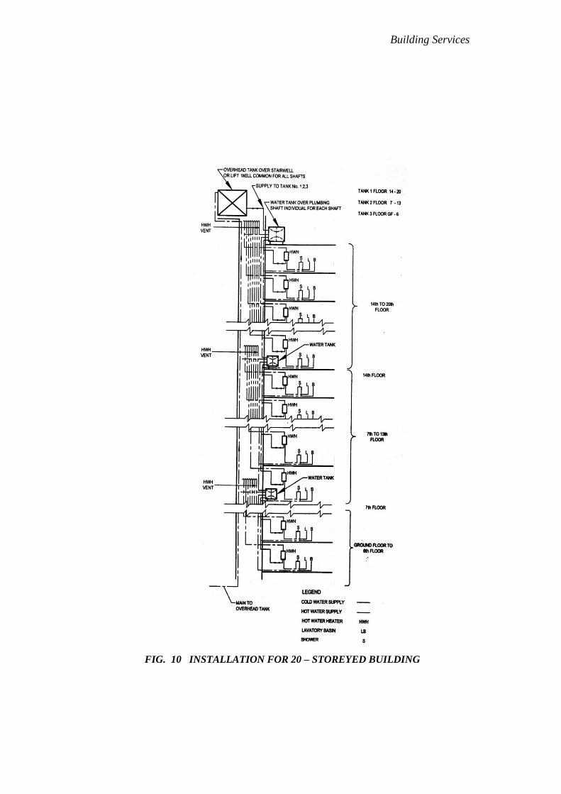
Building Services
FIG. 10 INSTALLATION FOR 20 – STOREYED BUILDING

Building Services
FIG. 11 INSTALLATION FOR 8 – STOREYED BUILDING
WITH INDIVIDUAL WATER TANKS

Building Services
Table 8: Maximum Permissible Lengths of Hot Water Draw-off Pipes
(Clause 4.13.12.2.3)
SI NO. Largest Internal Diameter of Pipe Length, feet
(1) (2) (3)
i) Not exceeding ¾ inch 40'
ii) Exceeding ¾ inch but not exceeding 1 inch 15'
iii) Exceeding 1 inch 10'
NOTE – In the case of a composite pipe of different diameters, the largest diameter is to
be taken into consideration for the purpose of this table.
5D.4.13.12.2.4
Wherever mixing of hot and cold water is done by a mixing fitting,
that is, hot and cold stop-cocks deliver to a common outlet of
mixed water (that is, showers, basin or bath supply fittings), the
pressure in the cold and hot water systems shall be equal. This can
be achieved by connecting the cold water supply from an
overhead tank at the same static height as the overhead tank
supplying cold water to the hot water heaters. In case this is not
possible, hot and cold water should be supplied to the fixtures by
separate supply taps.
5D.4.13.13 Types of Hot Water Heaters
The various types of water heaters used for preparation of hot water are as follows:
a) Electric Storage Heaters:
(1)Non-pressure or open outlet type,
(2)Pressure type,
(3)Cistern type, and
(4)Dual heater type.
b) Gas Water Heaters:
(1)Instantaneous type, and
(2)Storage type.
c) Solar Heating Systems:
(1)Independent roof mounted heating units, and
(2)Centrally banked heated system.
d) Central Hot Water System
(1)Oil fired, and
(2)Gas fired.

Building Services
5D.4.13.13.1
The quality and construction of the different types of hot water heaters shall
be in accordance with good practice [9-1(15)].
5D.4.13.13.2 Typical arrangement of water heater is shown in Fig. 12.
FIG. 12 NON – PRESSURE TYPE INSTALLATION
Building Services
5D.4.13.13.3
Requirements in regard to inspection and maintenance of hot water supply
installations shall be in accordance with 4.14.1 to 4.14.4.
5D.4.14 Inspection and Testing
5D.4.14.1 Testing of Mains Before Commencing Work
All pipes, fittings and appliances shall be inspected, before delivery at the site to
see whether they conform to accepted standards. All pipes and fittings shall be
inspected and tested by the manufacturers at their factory and shall comply with
the requirements of this Section. They shall be tested hydraulically under a
pressure equal to 1.5 times this maximum permissible working pressure or
under such greater pressure as may be specified. The pipes and fittings shall be
inspected on site before laying and shall be sounded to disclose cracks. Any
defective items shall be clearly marked as rejected and forthwith removed from
the site.
5D.4.14.2 Testing of Mains After Laying
After laying and jointing, the main shall be slowly and carefully charged with
water by providing a 1 inch inlet with a stop-cock, so that all air is expelled
from the main. The main is then allowed to stand full of water for a few days if
time permits, and then tested under pressure. The test pressure shall be 168 ft or
double the maximum working pressure, whichever is greater. The pressure
shall be applied by means of a manually operated test pump, or, in the case of
long mains or mains of a large diameter, by a power-driven test pump, provided
the pump is not left unattended. In either case, due precaution shall be taken to
ensure that the required test pressure is not exceeded. Pressure gauges shall be
accurate and shall preferably have been recalibrated before the test. The pump
having been stopped, the test pressure shall maintain itself without measurable
loss for at least 5 min. The mains shall be tested in sections as the work of
laying proceeds; it is an advantage to have the joints exposed for inspection
during the testing. The open end of the main may be temporarily closed for
testing under moderate pressure by fitting a water-tight expanding plug of
which several types are available. The end of the main and the plug shall be
secured by struts or otherwise, to resist the end thrust of the water pressure in
the mains.
5D.4.14.2.1
If the section of the main tested terminates into a sluice valve, the wedge of
the valve shall not be used to retain the water; instead the valve shall be
temporarily fitted with a blank flange, or, in the case of a socketed valve,
with a plug, and the wedge placed in the open position while testing. End
support shall be given as in 4.14.2.
5D.4.14.3 Testing of Service Pipes and Fittings
When the service pipe is complete, it shall be slowly and carefully charged with
water, allowing all air to escape, care being taken to avoid all shock or water
hammer. The service pipe shall then be inspected under working conditions of
pressure and flow. When all draw-offs taps are closed, the service pipe shall be
absolutely water-tight. All piping, fittings and appliances shall be checked for

Building Services
satisfactory support, and protection from damage, corrosion and frost. Because
of the possibility of damage in transit, cisterns shall be re-tested for
water-tightness on arrival at the site, before fixing.
5D.4.14.4
In addition to the provisions given in 4.14.1, provisions given in 4.14.4.1 to
4.14.4.3 shall also apply to hot water supply installations in regard to inspection
and testing.
5D.4.14.4.1 Testing of the system after installation
After the hot water system, including the hot water heaters, has been
installed, it shall be carefully charged with water, so that all air is
expelled from the system. The entire system shall then be hydraulically
tested to a pressure of 168 ft or twice the working pressure, whichever is
greater, for a period of at least half an hour after a steady state is reached.
The entire installation shall then be inspected visually for leakages, and
sweating. All defects found shall be rectified by removing and remaking
the particular section. Caulking of threads, hammering and welding of
leaking joints shall not be allowed.
5D.4.14.4.2 Hot water testing
After the system has been proved water-tight, the hot water heaters shall be
commissioned by connecting the same to the electrical supply. The system
shall then be observed for leakage in pipes due to expansion or overheating.
The temperature of water at outlets shall be recorded. The thermostats of the
appliances shall be checked and adjusted to temperatures specified in
5D.4.13.2.1.
5D.4.14.4.3 Electrical connection
For relevant provisions regarding general and safety requirements for
household and similar electrical appliances, reference may be made to good
practice [9-1(14)]. The metal work of the water heating appliances and
installation other than current carrying parts shall be bonded and earthed in
conformity with the good practice [9-1(14)]. It should be noted that screwing
of an immersion heater into a tank or cylinder cannot be relied upon to effect
a low resistance earth connection, a satisfactory separate earthing of heater
should be effected.
5D.4.15 Cleaning and Disinfection of the Supply System
5D.4.15.1
All water mains communications pipes, service pipes and pipes used for
distribution of water for domestic purposes shall be thoroughly and efficiently
disinfected before being taken into use and also after every major repair. The
method of disinfection shall be subject to the approval of the Authority. The pipes
shall also be periodically cleaned at intervals, depending upon the quality of
water, communication pipes and the storage cisterns shall be thoroughly cleaned
at least once every year in order to remove any suspended impurities that may
have settled in the pipes or the tanks.
Building Services
5D.4.15.2 Disinfection of Storage Tanks and Downtake Distribution Pipes
The storage tanks and pipes shall first be filled with water and thoroughly flushed
out. The storage tank shall then be filled with water again and a disinfecting
chemical containing chlorine added gradually while the tanks are being filled, to
ensure thorough mixing. Sufficient quantities of chemicals shall be used to give the
water a dose of 50 parts of chlorine to one million parts of water. If ordinary
bleaching powder is used, the proportions will be 0.33 lb of powder to 220 gallons
of water. The powder shall be mixed with water to a creamy consistency before
being added to the water in the storage tank. When the storage tank is full, the
supply shall be stopped and all the taps on the distributing pipes opened
successively working progressively away from the storage tank. Each tap shall be
closed when the water discharged begins to smell of chlorine. The storage tank
shall then be topped up with water from the supply pipe and with more disinfecting
chemical in the recommended proportions. The storage tank and pipes shall then
remain charged for at least 3 hours. Finally, the tank and pipes shall be thoroughly
flushed out before any water is used for domestic purposes.
5D.4.16 Water Supply Systems in High Altitudes and/ or Sub-zero Temperature
Regions
5D.4.16.1 Selection and Source
In general, the site selected for a water source shall be such as to minimize the
length of transmission line so as to reduce the inspection and upkeep. Attempt shall
be made, where feasible, to locate the source near the discharge of waste heat, such
as of power plants provided it does not affect the potability of water.
5D.4.16.2 Pumping Installation
Pump and pumping machinery shall be housed inside well-insulated chambers.
Where necessary, arrangements shall be made for heating the inside of pump
houses. Pump houses, as far as possible, should be built directly above the water
intake structures.
5D.4.16.3 Protection of Storage Water and Treatment
Where ambient temperatures are so low as to cause danger of freezing, proper
housing, insulation and protection shall be provided for all processes and
equipment. If necessary, means shall be provided for proper heating of the
enclosure.
5D.4.16.4 Transmission and Distribution
Freezing of the buried pipe may be avoided primarily by laying the pipe below the
level of the frost line; well consolidated bedding of clean earth or sand, under,
around or over the pipe should be provided. For the efficient operation and design
of transmission and distribution work, the available heat in the water shall be
economically utilized and controlled. If the heat which is naturally present in water
is made equate to satisfy heat losses from the system, the water shall be warmed.
Where economically feasible, certain faucets on the distribution system may be
kept in a slightly dripping condition so as to keep the fluid in motion and thus
prevent is freezing. If found unsuitable for drinking purposes, such water may be
used for heating purposes. Heat losses shall be reduced by insulation, if necessary.
Any material that will catch, absorb or hold moisture shall not be used for
Building Services
insulation purposes. Adequate number of break pressure water tanks and air
release valves shall be provided in the distribution system.
NOTE — The level of frost line is generally found to be between 3 ft and 4 ft
below ground level in the northern regions of MYANMAR, wherever freezing
occurs.
5D.4.16.4.1 Materials for pipes
Distribution pipes shall be made of any of the following materials
conforming to Part 5 'Building Materials':
(a) high density polyethylene pipes,
(b) asbestos cement pipes,
(c) galvanized iron pipes,
(d) cast iron pipes, and
(e) unplasticized PVC pipes (where it is laid before frost line).
5D.4.16.4.2 Materials for insulation of pipes
The normal practice in MYANMAR is to surround the pipe with straw,
grass or jute wrapped over with gunny and painted with bitumen;
alternatively, other materials, like 85 percent magnesia, glass wool, etc, or
with the approval of the Authority may also be used.
5D.4.16.4.3 Distribution methods
Distribution by barrels or tank trucks shall be employed, where the water
requirements are temporary and small. Utmost care shall be exercised for
preventing the water from being contaminated by maintaining a residual of
disinfecting agent at all times. Hoses, pails and the tank shall be kept free
from dust and filth during all period of operation. Where winter
temperatures are low, making frost penetration depths greater during the
winter, and where adequate facilities for heating the water in the
distribution system do not exist, the use of tank trucks or barrels for
delivery of water shall be considered only for cold weather; during the
warm weather, piping system for seasonal use may be supplemented.
5D.4.16.4.4
In the conventional distribution system involving the use of a network of
pipelines requiring no auxiliary heat, it is essential that the pipelines are
buried well below the frost line. Adequate facilities for draining the
pipelines shall be provided where there is a danger of frost.
5D.4.16.4.5 House service connections
House service connections shall be kept operative by the use of adequate
insulation at exposed places extending below the frost line. Figure 10
shows a typical arrangement for providing insulation for house service
connections.

Building Services
5D.4.16.5
For detailed information on planning and designing water supply system peculiar
to high altitudes and/or sub-zero temperature regions of the country, reference
may be made to good practice [9-1(16)].
5D.4.17 Guidelines to Maintenance
5D.4.17.1
Storage tanks shall be regularly inspected and shall be cleaned out periodically, if
necessary. Tanks showing signs of corrosion shall be emptied, thoroughly wire
brushed to remove loose material (but not scraped), cleaned and coated with suitable
bituminous compositions or other suitable anti- corrosive material not liable to impart
taste or odor or otherwise contaminate the water. Before cleaning the cistern, the
outlets shall be plugged to prevent debris from entering the pipes. Tanks shall be
examined for metal wastage and water tightness after cleaning.
5D.4.17.2
Record drawings showing pipe layout and valve positions shall be kept up to date
and inspection undertaken to ensure that any maintenance work has not
introduced cross-connections or any other undesirable feature. Any addition or
alterations to the systems shall be duly recorded from time-to-time.
5D.4.17.3
Any temporary attachment fixed to a tap or outlet shall never be left in such a
position that back-siphonage of polluted water may occur into the supply system.
5D.4.17.4
All valves shall periodically be operated to maintain free movement of the
working parts.
5D.4.17.5
All taps and ball valves shall be watertight, glands shall be made good, washers
shall be replaced and the mechanism of spring operated taps and ball valves shall
be repaired where required.
5D.4.17.6
All overflow pipes shall be examined and kept free from obstructions.
5D.4.17.7
The electrical installation shall be checked for earth continuity and any defects or
deficiencies corrected in the case of hot water supply installations.
Building Services
5D.5 DRAINAGE AND SANITATION
5D.5.1 Types of Sanitary Appliances
5D.5.1.1 Soil Appliances
5D.5.1.1.1 Water-closet
It shall essentially consist of a closet consisting of a bowl to receive
excretory matter, trap and a flushing apparatus. It is recommended to
provide ablution tap adjacent to the water-closet, preferably on right
hand side wall. The various types/style of water-closets may be:
a) Squatting Indian type water closet,
b) Washdown type water closet,
c) Siphonic washdown type water closet, and
d) Universal or Anglo-Indian water closet.
5D.5.1.1.2 Bidet
It is provided with hot and cold water connection. The bidet outlet should
essentially connect to soil pipe in a two-pipe system.
5D.5.1.1.3 Urinal
It is a soil appliance and is connected to soil pipe after a suitable trap. Urinal
should have adequate provision of flushing apparatus. The various
types/style of urinal may be:
a) Bowl type urinal: Flat back or Angle back,
b) Slab (single) type urinal,
c) Stall (single) type urinal,
d) Squatting plate type urinal, and
e) Syphon jet urinal with integral trap.
5D.5.1.1.4 Slop sink and bed pan sink
Slop sink is a large sink of square shape. The appliance is used in hospitals
installed in the nurse's station, operation theatres and similar locations for
disposal of excreta and other foul waste for washing bed pans and urine
bottles/pans. It is provided with a flushing mechanism.
5D.5.1.2 Waste Appliances
5D.5.1.2.1 Washbasin
It is of one piece construction having a combined overflow and preferably
should have soap holding recess or recesses that should properly drain into
the bowl. Each basin shall have circular waste hole through which the liquid
content of the basin shall drain.

Building Services
5D.5.1.2.2 Wash-trough
It is a linear trough for simultaneous use by number of persons.
5D.5.1.2.3 Sink
It is used in kitchen and laboratory for the purpose of cleaning
utensils/apparatus and also serve the purpose of providing water for general
usage. The sink may be made with or without overflow arrangement. The
sink shall be of one piece construction including combined over flow,
where provided. The sink shall have a circular waste hole into which the
interiors of the sink shall drain.
5D.5.1.2.4 Bath tub
Bath tub may be of enameled steel, cast iron, gel- coated, glass fibre
reinforced plastic or may be cast in-situ. It shall be stable, comfortable, easy
to get in and out, water tight, with anti-skid base, and easy to install and
maintain. The bath tub shall be fitted with overflow and waste pipe of
nominal diameter of not less than 1.25 inches and 1.5 inches respectively.
5D.5.1.2.5 Drinking fountain
It is a bowl fitted with a push button tap and a water bubbler or a tap with a
swan neck outlet fitting. It has a waste fitting, a trap and is connected to the
waste pipe.
5D.5.1.3
The requirements of various soil appliances and waste appliances shall be in
accordance with accepted standards [9-1(17)].
5D.5.2 Drainage and Sanitation Requirements
5D.5.2.1 General
There should be at least one water tap and arrangement for drainage in the vicinity
of each water-closet or group of water-closet in all the buildings.
5D.5.2.2
Each family dwelling unit on premises (abutting on a sewer or with a private
sewage disposal system) shall have, at least, one water-closet and one kitchen
type sink. A bath or shower shall also be installed to meet the basic requirements
of sanitation and personal hygiene.
5D.5.2.3
All other structures for human occupancy or use on premises, abutting on a sewer
or with a private sewage-disposal system, shall have adequate sanitary facilities,
but in no case less than one water-closet and one other fixture for cleaning
purposes.
5D.5.2.4 For Residences
5D.5.2.4.1
Dwelling with individual convenience shall have at least the following
fitments:
a) One bathroom provided with a tap and a floor trap;

Building Services
b) One water-closet with flushing apparatus with an ablution tap; and
c) One tap with a floor trap or a sink in kitchen or wash place.
5D.5.2.4.1.1
Where only one water-closet is provided in a dwelling, the bath and
water-closet desirably shall be separately accommodated.
NOTE — Water-closets, unless indicated otherwise, shall be of
Indian style (squatting type).
5D.5.2.4.2
Dwellings without individual conveniences shall have the following
fitments:
a) One water tap with floor trap in each tenement,
b) One water-closet with flushing apparatus and one ablution tap
bath
for every two tenements, and
c) One bath with water tap and floor trap for every two tenements.
5D.5.2.5 For Buildings Other than Residences
5D.5.2.5.1
The requirements for fitments for drainage and sanitation in the case of
buildings other than residences shall be in accordance with Table 9 to Table
22. The following shall be, in addition, taken into consideration:
a) The figures shown are based upon one (1) fixture being the
minimum
required for the number of persons indicated or part thereof.
b) Building categories not included in the tables shall be considered
separately by the Authority.
c) Drinking fountains shall not be installed in the toilets.
d) Where there is the danger of exposure to skin contamination with
poisonous, infectious or irritating material, washbasin with eye
wash jet and an emergency shower located in an area accessible at
all times with the passage/ right of way suitable for access to a
wheel chair, shall be provided.
e) When applying the provision of these tables for providing the
number of fixtures, consideration shall be given to the
accessibility of the fixtures. Using purely numerical basis may not
result in an installation suited to the need of a specific building.
For example, schools should be provided with toilet facilities on
each floor. Similarly toilet facilities shall be provided for
temporary workmen employed in any establishment according to
the needs; and in any case one WC and one washbasin shall be
provided.

Building Services
f) All buildings used for human habitation for dwelling, work,
occupation, medical care or any purpose detailed in the various
tables, abutting a public sewer or a private sewage disposal
system, shall be provided with minimum sanitary facilities as per
the schedule in the tables. In case the disposal facilities are not
available, they shall be provided as a part of the building design
for ensuring high standards of sanitary conditions in accordance
with this section. The location of the facility or facilities shall be
selected with due regard given to health, sanitary and environment
requirements, within the building's jurisdiction.
g) Workplaces where crèches are provided, they shall be provided
with one WC for 10 persons or part thereof, one washbasin for 15
persons or part thereof, one kitchen sink with floor trap for
preparing food/milk preparations. The sink provided shall with a
drinking water tap.
h) In all types of buildings, individual toilets and pantry should be
provided for executives, and for meeting/seminar/conference
rooms, etc as per the user requirement.
j) Where food is consumed indoors, water stations may be provided
in place of drinking water fountains.
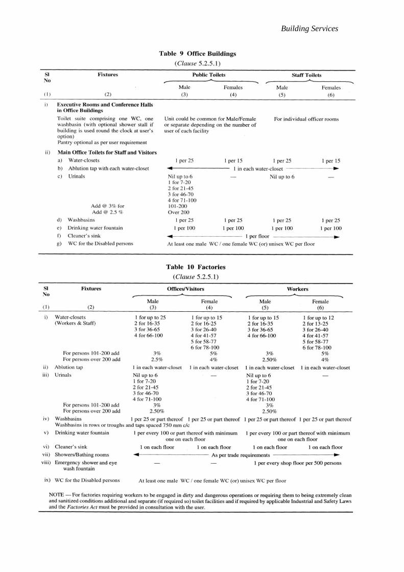
Building Services
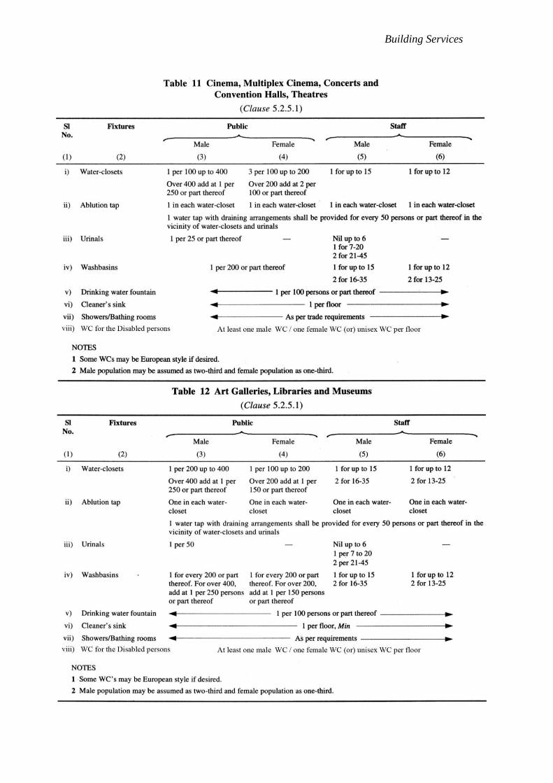
Building Services

Building Services
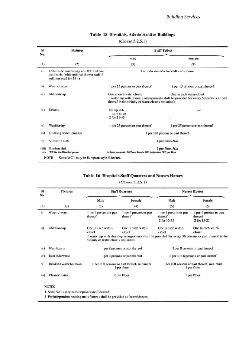
Building Services

Building Services

Building Services

Building Services
5D.5.3 Materials, Fittings and Appliances
5D.5.3.1 Standards for Materials, Fittings and Sanitary Appliances
All materials, fittings and sanitary appliances shall conform to Part 5
'Building Materials'.
5D.5.3.2 Choice of Material for Pipes
5D.5.3.2.1 Salt glazed stoneware pipe
For all sewers and drains in all soils, except where supports are required as
in made-up ground, glazed stoneware pipe shall be used as far as possible in
preference to other types of pipes. These pipes are particularly suitable
where acid effluents or acid subsoil conditions are likely to be encountered.
Salt glazed stoneware pipes shall conform to accepted standards [9-1(18)].
5D.5.3.2.2 Cement concrete pipes
When properly ventilated, cement concrete pipes with spigot and socket or
collar joints present an alternative to glazed stoneware sewers of over 6
inches diameter. These shall not be used to carry acid effluents or sewage
under conditions favourable for the production of hydrogen sulphide and
shall not be laid in those sub soils that are likely to affect adversely the
quality or strength of concrete. Owing to the longer lengths of pipes
available, the joints would be lesser in the case of cements concrete pipes.
These pipes may be used for surface water drains in all diameters. Cement
concrete pipes shall conform to accepted standards [9-1(19)].
5D.5.3.2.3 Cast iron pipes
5D.5.3.2.3.1
These pipes shall be used in the following situation:
a) in bed or unstable ground where soil movement is
expected;
b) in-made-up or tipped ground;
c) to provide for increased strength where a sewer is laid at
insufficient depth, where it is exposed or where it has to
be carried on piers or above ground;
d) under buildings and where pipes are suspended in
basements
and like situations;
e) in reaches where the velocity is more than 9 ft/s; and
f) for crossings of watercourses.
NOTE — In difficult foundation condition such as in the case of
black cotton soil, the cast iron pipes shall be used only when
suitable supporting arrangements are made.

Building Services
5D.5.3.2.3.2
It shall be noted that cast iron pipes even when given a protective
paint are liable to severe external corrosion in certain soils; among
such soils are:
a) soils permeated by peaty waters; and
b) soils in which the sub-soil contains appreciable concentrations of
sulphates. Local experiences shall be ascertained before cast iron
pipes are used where corrosive soil conditions are suspected.
Where so used, suitable measures for the protection of the pipes
may be resorted to as an adequate safeguard.
5D.5.3.2.3.3
Cast iron pipes shall conform to accepted standards [9-1(20)].
5D.5.3.2.4 Asbestos cement pipes
Asbestos cement pipes are commonly used for house drainage
systems and they shall conform to accepted standards [9-1(21)]. They
are not recommended for underground situations. However, asbestos
cement pressure pipes conforming to accepted standards [9-1(21)]
may be used in underground situations also, provided they are not
subject to heavy superimposed loads. These shall not be used to carry
acid effluents or sewage under conditions favourable for the
production of hydrogen sulphide and shall not be laid in those
sub-soils which are likely to affect adversely the quality or strength of
asbestos cement pipes. Where so desired, the life of asbestos cement
pipes may be increased by lining inside of the pipe with suitable
coatings like epoxy/polyester resins etc.
5D.5.3.2.5 PVC pipes
Unplasticized PVC pipes may be used for drainage purposes;
however, where hot water discharge is anticipated, the wall thickness
shall be minimum 0.1inches irrespective of the size and flow load.
PVC and HDPE pipes shall conform to accepted standards [9-1(23)].
NOTE — Where possible, high density polyethylene pipes (HDPE) and
PVC pipes may be used for drainage and sanitation purposes, depending
upon the suitability.
5D.5.4 Preliminary Data for Design
5D.5.4.1 General
Before the drainage system for a building or group of buildings is designed and
constructed, accurate information regarding the site conditions is essential. This
information may vary with the individual scheme but shall, in general, be
covered by the following:
(a) Site Plan (see 5D.3.3.2).
(b) Drainage Plan (see 5D.3.3.3).

Building Services
(c) Use — A description of the use for which the building is intended and periods
of occupation in order that peak discharges may be estimated;
(d) Nature of Waste — While dealing with sewage from domestic premises,
special problems under this head may not arise; however, note shall be taken of
any possibility of trade effluents being discharged into the pipes at a future date;
(e) Outlet Connection — The availability of sewers or other outlets;
(f) Cover — The depth (below ground) of the proposed sewers and drains and the
nature and weight of the traffic on the ground above them;
(g) Sub-soil Condition:
(1)The approximate level of the subsoil water, and any available records of flood
levels shall be ascertained, as also the depth of the water table relative to all
sewer connections, unless it is known to be considerably below the level of the
latter;
(2)In the case of deep manholes, this information will influence largely the type of
construction to be adopted. The probable safe bearing capacity of the subsoil at
invert level may be ascertained in the case of a deep manhole.
(3)Where work of any magnitude is to be undertaken, trial pits or boreholes shall
be put at intervals along the line of the proposed sewer or drain and the data
therefrom tabulated, together with any information available from previous
works carried out in the vicinity. In general the information derived from trial
pits is more reliable than that derived from boreholes. For a long length of
sewer or drain, information derived from a few trial pits at carefully chosen
points may be supplemented by that obtained from number of intermediate
boreholes. Much useful information is often obtained economically and quickly
by the use of a soil auger;
(4)The positions of trial pits or boreholes shall be shown on the plans, together
with sections showing the strata found and the dates on which water levels are
recorded.
(a)Location of Other Services — The position, depth and size of all other pipes,
mains, cables, or other services, in the vicinity of the proposed work, may be
ascertained from the Authority, if necessary;
(b)Reinstatement of Surfaces — Information about the requirements of the
highway authority is necessary where any part of the sewer or drain is to be
taken under a highway. Those responsible for the sewer or drain shall be also
responsible for the maintenance of the surface until permanently reinstated. The
written consent of the highway authority to break up the surface and
arrangement as to the charges thereof and the method and type of surface
reinstatement shall always be obtained before any work is commenced;
(c)Diversion and Control of Traffic
In cases where sewers cross roads or footpaths, cooperation shall be maintained
with the police and Authorities regarding the control and diversion of vehicular
and/or pedestrian traffic as may be necessary. Access to properties along the
road shall always be maintained and adequate notice shall be given to the

Building Services
occupiers of any shops or business premises, particularly if obstruction is
likely;
During the period of diversion, necessary danger lights, red flags, diversion
boards, caution boards, watchmen, etc, shall be provided as required by the
Authority;
(d)Way-leaves (Easements) — The individual or authority carrying out the work
is responsible for negotiating way-leaves where the sewer crosses land in other
ownership. The full extend and conditions of such way-leaves shall be made
known to the contractor and his employees, and prior notice of commencement
of excavation shall always be given to the owners concerned, and cooperation
with them shall be maintained at all stages, where sewers run across fields or
open ground, the exact location of manholes shall be shown on way-leaves or
easement plans. The right of access to manhole covers and the right to maintain
the sewer shall be specifically included in any way-leave or easement
arrangements which may be made with the owner of the land; and
(e)Damage to Buildings and Structures — When sewer trenches have to be
excavated near buildings or walls a joint inspection with the owners of the
property shall be made to establish whether any damage or cracks exist before
starting the work, and a properly authenticated survey and record of the
condition of buildings likely to be affected shall be made. Tell tales may be
placed across outside cracks and dated, and kept under observation.
Un-retouched photographs taken by an independent photographer may provide
useful evidence.
5D.5.4.2 Drainage into a Public Sewer
Where public sewerage is available, the following information is particularly
necessary and may be obtained from the Authority:
(a) the position of the public sewer or sewers in relation to the proposed buildings;
(b) the invert level of the public sewer;
(c) the system on which the public sewers are designed (combined, separate or
partially separate), the lowest level at which connection may be made to it, and
the Authority in which it is vested;
(d) the material of construction and condition of the sewer if connection is not to be
made by the Authority;
(e) the extent to which surcharge in the sewer may influence the drainage scheme;
(f) whether the connection to the public sewer is made, or any part of the drain laid,
by the Authority, or whether the owner is responsible for this work; if the latter,
whether the Authority imposes any special conditions;
(g) whether an intercepting trap is required by the Authority on the drain near the
boundary of the curtilage; and
(h) where manholes are constructed under roads, the approval of the Highway
Authority for the type of cover to be fitted shall be obtained.

Building Services
5D.5.4.3 Other Methods of Disposal of Sewage
5D.5.4.3.1
Where discharge into a public sewer is not possible, the drainage of the
building shall be on a separate system. Foul water shall be disposed of by
adequate treatment approved by the Authority on the site. The effluent
from the plant shall be discharged into a natural watercourse or public
drain or disposed into sub-soil, preferably a porous sub-soil. The treated
soil water shall have effluent quality of BOD5 =20 mg/L, SS= 30 mg/L,
COD= 60 mg/L and the effluent must be chlorinated before being
discharged. 5D.5.4.3.2
In the case of dilution into a natural stream course, the quality of the
effluent shall conform to the requirements of the Authority controlling
the prevention of pollution of streams.
5D.5.4.3.3
In the case of sub-soil dispersion, the requirements of the Authority for
water supply shall be observed to avoid any possible pollution of local
water supplies or wells.
5D.5.4.3.4
The general sub-soil water level and the subsoil conditions shall be
ascertained, including the absorptive capacity of the soil.
5D.5.4.3.5
A sub-soil dispersion is not desirable near a building or in such positions
that the ground below the foundations is likely to be affected.
5D.5.4.3.6
Under the separate system, drainage of standard the building shall be
done through septic tanks of different sizes or by stabilization ponds or
by any other methods approved by the Authority.
For detailed information on the design and construction of septic tanks
and waste stabilization ponds, reference may be made to good practice
[9-2(24)].
5D.5.4.4 Disposal of Surface and Sub-soil Waters
All information which may influence the choice of methods of disposal of
surface and/or sub-soil waters shall be obtained. In the absence of surface water
drainage system, and if practicable and permissible, disposal into a natural
water-course or soakaway may be adopted. The location and flood levels of the
water course as also the requirements of the Authority controlling the river or
the waterway shall be ascertained.

Building Services
5D.5.5 Planning and Design Considerations
5D.5.5.1 Aim
The efficient disposal of foul and surface water from a building is of great
importance to public health and is an essential part of the construction of the
building. In designing a drainage system for an individual building or a housing
colony, the aim shall be to provide a system of self-cleaning conduits for the
conveyance of foul, waste, surface or subsurface waters and for the removal of
such wastes speedily and efficiently to a sewer or other outlet without risk of
nuisance and hazard to health.
5D.5.5.1.1
To achieve this aim a drainage system shall satisfy the following
requirements:
a) rapid and efficient removal of liquid wastes without leakage;
b) prevention of access of foul gases to the building and provision for
their escape from the system.
c) adequate and easy access for clearing obstructions;
d) prevention of undue external or internal corrosion, or erosion of joints
and protection of materials of construction; and
e) avoidance of air locks, siphonage, proneness to obstruction, deposit
and damage.
5D.5.5.1.2
The realization of an economical drainage system is added by compact
grouping of fitments in both horizontal and vertical directions. This
implies that if care is taken and ingenuity brought into play when
designing the original building or buildings to be drained, it is possible to
group the sanitary fittings and other equipment requiring drainage; both
in vertical and horizontal planes, as to simplify the drainage system and
make it most economical.
5D.5.5.1.3
Efficient and an economical plumbing system can be achieved by
planning the toilets in compact grouping with the layout of the
bathrooms and observing the following guidelines:
a) Placing of plumbing fixtures around an easily accessible pipe shaft; in
high rise buildings the pipe shafts may have to be within the building
envelope and easy provision for access panels and doors should be
planned in advance, in such cases.
b) Adopting repetitive layout of toilets in the horizontal and vertical
directions.
c) Avoiding any conflict with the reinforced cement concrete structure
by avoiding embedding pipes in it, avoiding pipe crossings in beams,
columns and major structural elements.

Building Services
d) Identifying open terraces and areas subject to ingress of rainwater
directly or indirectly and providing for location of inlets at each level for
down takes for disposal at ground levels.
e) Avoiding crossing of services of individual property through
property of other owners.
f) Planning to avoid accumulation of rain water or any backflow from
sewers particularly in planned law elevation areas in a building.
5D.5.5.2 Layout
5D.5.5.2.1 General
Rain-water should preferably be dealt separately from sewage and
sullage. Sewage and sullage shall be connected to sewers. However,
storm water from the courtyard may be connected to the sewer where it is
not possible to drain otherwise; after obtaining permission of the
Authority.
5D.5.5.2.2 Additional Requirement
The following requirements are suggested to be considered in the design
of drainage system:
a) The layout shall be as simple and direct as practicable.
b) The pipes should be laid in straight lines, as far as possible, in both
vertical and horizontal planes.
c) Anything that is likely to cause irregularity of flow, as abrupt changes
of direction, shall be avoided.
d) The pipes should be non-absorbent, durable, smooth in bore and of
adequate strength.
e) The pipes should be adequately supported without restricting
movement.
f) Drains should be well ventilated, to prevent the accumulation of foul
gases and fluctuation of air pressure within the pipe, which could lead
to unsealing of gully or water-closet traps.
g) All the parts of the drainage system should be accessible for
feasibility of inspection and practical maintenance.
h) No bends and junctions whatsoever shall be permitted in sewers
except at manholes and inspection chambers.
i) Sewer drain shall be laid for self-cleaning velocity of 2.5 ft/s and
generally should not flow more than half-full.
j) Pipes crossing in walls and floors shall be through mild steel sleeves
of diameter leaving an annular space of 0.2 inches around the outer
diameter of the pipe crossing the wall.
k) Pipes should not be laid close to building foundation.

Building Services
l) Pipes should not pass near large trees because of possibility of
damage by the roots.
m) Branch connections should be swept in the direction of flow.
n) Sewer pipes should be at least 3 ft below road and at least 2 ft below
fields and gardens.
o) Pipes should not pass under a building unless absolutely necessary.
p) Where it is necessary to lay pipes under a building, the following
conditions shall be observed:
1) Pipes shall be cast iron pressure pipe as per good practice [9-2(20)];
2) The pipe shall be laid in straight line and at uniform gradient;
3) Means of access in form of manholes/ inspection chamber shall be
provided at each end, immediately outside the building; and
4) In case the pipe or any part of it is laid above the natural surface of
the ground, it shall be laid on concrete supports, the bottom of which
goes at least 6 inches below the ground surface.
NOTE — It is desirable that pipe/drains should not be taken through a
living room or kitchen and shall preferably be taken under a staircase
room or passage.
q) Consideration shall be given to alternative layouts so as to ensure that
the most economical and practical solution is adopted. The possibility of
alterations shall be avoided exercising due care and forethought.
5D.5.5.2.3 Protection against vermin and dirt
The installation of sanitary fittings shall not introduce crevices which are
not possible to inspect and clean readily.
Pipes, if not embedded, shall be run well clear of the wall. Holes through
walls to taken pipes shall be made good on both sides to prevent entry of
insects. Materials used for embedding pipes shall be rodent-proof.
Passage of rodents from room-to-room or from floor- to-floor shall be
prevented by suitable sealing. The intermediate lengths of ducts and
chases shall be capable of easy inspection. Any unused drains, sewers,
etc, shall be demolished or filled in to keep them free from rodents.
All pipe shafts shall be plastered before any pipes are installed in the
shaft. This will provide a smooth surface and prevent location for
survival of insects and vermins.
5D.5.5.2.4 Choice of plumbing system
In selecting one or more of the type of piping systems, the building and
the layout of toilets; relationship with other services; acceptability to the
Authority; and any special requirements of users, shall be studied.
(a) Two-pipe system
(1) This system is ideal when the location of toilets and stacks for the WCs
and waste fittings is not uniform or repetitive.

Building Services
(2) In large buildings and houses with open ground and gardens the sullage
water from the waste system can be usefully utilized for gardening and
agriculture.
(3) In larger and multi-storied buildings, the sullage is treated within the
building for re-use as makeup water for cooling towers for air
conditioning system and is also used for flushing water-closets provided
it has absolutely no connection with any water supply line, tank or
system used for domestic and drinking supply.
(b) One-pipe system
(1) This system is suitable for buildings where the toilet layouts and the
shafts are repetitive. It requires less space, and is economical.
(2) Continuous flow of water in the pipe from waste appliances makes it less
prone to blockage and makes the system more efficient.
(3) The system eliminates the need for a gully trap which requires constant
cleaning.
(4) The system is ideal when the main pipes run at the ceiling of the lowest
floor or in a service floor. Two-pipe system may present space and
crossing problems which this system eliminates.
(c) Single stack system
(1) The single stack system (without any vent pipe) is ideal when the toilet
layouts are repetitive and there is less space for pipes on the wall.
(2) In any system so selected there should be not more than two toilet
connections per floor.
(3)The system requires minimum 4 inches diameter stack for a maximum of
five floors in a building.
(4)All the safeguards for the use of this system given in 5.5.2.4.1 shall be
complied with.
(d) Single stack system (partially ventilated)
(1)The system and the applicable safeguards under this system are the same
as for single stack system. The prime modification is to connect the
waste appliances, such as wash basin, bath tub or sink to a floor trap.
(2)For detailed information regarding design and installation of soil, waste
and ventilating pies, reference may be made to good practice [9-2(25)].
5D.5.5.2.4.1 Safeguards for single stack system
a) as far as practicable, the fixtures on a floor shall be connected to
stack in order of increasing discharge rate in the downward
direction;
b) the vertical distance between the waste branch (from floor trap or
from the individual appliance) and the soil branch connection,
when soil pipe is connected to stack above the waste pipe, shall
be not less than 8 inches;

Building Services
c) depth of water seal traps from different fixtures shall be as
follows:
Water closets 2 inches
Floor traps 2 inches
Other fixtures directly connected to the stack.
1) Where attached to branch waste pipes of 3 inches dia or more
1.5 inches
2) Where attached to branch waste pipes of less than 3 inches dia
3 inches
NOTE — When connection is made through floor trap, no separate
seals are required for individual fixtures.
d) branches and stacks which receive discharges from WC pans
should not be less than 4 inches, except where the outlet from the
siphonic water closet is 3¼ inches, in which case a branch pipe of
3¼ inches may be used. For outlet of floor traps 3 inches dia pipes
may be used;
e) the horizontal branch distance for fixtures from stack, bend(s) at
the foot of stack to avoid back pressure as well as vertical distance
between the lowest connection and the invert of drain shall
be as shown in Fig. 2A; and
f) for tall buildings, ground floor appliances are recommended to be
connected directly to manhole/inspection chamber.
5D.5.5.3 Drainage (Soil, Waste and Ventilating) Pipes
5D.5.5.3.1 General considerations
5D.5.5.3.1.1
Drainage pipes shall be kept clear of all other services. Provisions
shall be made during the construction of the building for the entry
of the drainage pipes. In most cases this may be done conveniently
by building sleeves or conduit pipes into or under the structure in
appropriate positions. This will facilitate the installation and
maintenance of the services.
5D.5.5.3.1.2
Horizontal drainage piping should be so routed as not to pass over
any equipment or fixture where leakage from the line could
possibly cause damage or contamination. Drainage piping shall
never pass over switch-gear or other electrical equipment. If it is
impossible to avoid these areas and piping must run in these
locations, then a pan or drain tray should be installed below the
pipe to collect any leakage or condensation. A drain line should
run from this pan to a convenient floor drain or service sink.

Building Services
5D.5.5.3.1.3
All vertical soil, waste, ventilating and anti- siphonage pipes shall
be covered on top with a copper or heavily galvanized iron wire
dome or cast iron terminal guards. All cast iron pipes, which are to
be painted periodically, shall be fixed to give a minimum
clearance of 2 inches clear from the finished surface of the wall by
means of a suitable clamps.
NOTE — Asbestos cement cowls may be used in case asbestos
cement pipes are used as soil pipes.
5D.5.5.3.1.4
Drainage pipes shall be carried to a height above the buildings as
specified for ventilating pipe (see5D. 5.5.3.4).
5D.5.5.3.2 Soil pipes
A soil pipe, conveying to a drain, any solid or liquid filth, shall be
circular and shall have a minimum diameter of 4 inches.
5D.5.5.3.2.1
Except where it is impracticable, the soil pipe shall be situated
outside the building or in suitably designed pipe shafts and shall
be continued upwards without diminution of its diameter, and
(except where it is unavoidable) without any bend or angle, to
such a height and position as to afford by means of its open end a
safe outlet for foul air. The position of the open end with its
covering shall be such as to comply with the conditions set out in
5D.5.5.3.4 relating to ventilating pipe. Even if the pipes are laid
externally, the soil pipes shall not be permitted on a wall abutting
a street unless the Authority is satisfied that it is unavoidable.
Where shafts for pipes are provided, the cross-sectional area of the
shaft shall be suitable to allow free and unhampered access to the
pipes and fittings proposed to be installed in the shaft. However in
no case cross- section area of the shaft shall be less than a square
of one meter side. All pipe shafts shall be provided with an access
door at ground level and facilities for ventilation.
5D.5.5.3.2.2
Soil pipes, whether insider or outside the building, shall not be
connected with any rainwater pipe and there shall not be any trap
in such soil pipe or between it and any drain with which it is
connected.
5D.5.5.3.2.3
Soil pipes shall preferably be of cast iron. Asbestos cement
building pipes may also be used as soil pipes only above ground
level.

Building Services
5D.5.5.3.2.4
The soil pipe shall be provided with heel rest bend which shall rest
on sound footing, if terminating at firm ground level. When the
stack is terminating at the ceiling of a floor, the bend shall be
provided with sufficient structural support to cater for the stack
dead weight and the thrust developed from the falling soil/waste.
Vertical stack shall be fixed at least 2 inches clear of the finished
surface of the wall by means of a suitable clamps of approved
type.
5D.5.5.3.3 Waste pipes
Every pipe in a building for carrying off the waste or overflow water
from every bath, washbasin or sink to a drain shall be of 1¼ inches to 2
inches diameter, and shall be trapped immediately beneath such
washbasins or sink by an efficient siphon trap with adequate means for
inspection and cleaning. Such traps shall be ventilated into the external
air whenever such ventilation is necessary to preserve the seal of the trap.
Waste pipes, traps, etc, shall be constructed of iron, lead, brass,
stoneware, asbestos cement or other approved material. The overflow
pipe from washbasin, sinks, etc, shall be connected with the waste pipe
immediately above the trap. Vertical pipes carrying off waste water shall
have a minimum diameter of 3 inches.
NOTE — Whenever washbasins and sinks have in-built overflow
arrangements, there is no need to provide overflow pipes in such cases.
5D.5.5.3.3.1
Every pipe in a building for carrying off waste water to a drain
shall be taken through an external wall of the building by the
shortest practicable line, and shall discharge below the grating or
surface box of the chamber but above the inlet of a properly
trapped gully. The waste pipe shall be continued upwards without
any diminution in its diameter and (except when unavoidable)
without any bend or angle to such a height and position as to
afford by means of the open end of the waste pipe, a safe outlet for
foul air, the position of the open end and its covering being such as
to comply with the conditions.
5D.5.5.3.3.2
Except where it is impracticable, the common waste pipe shall be
situated outside the building and shall be continued upwards
without diminution of its diameter (except where it is
unavoidable) without any bend or angle being formed to such a
height and position as to avoid by means of the open end a safe
outlet for foul air, the position of the open end and the covering
threat being such as to comply with the conditions set out in
5.5.3.4 relating to ventilating pipe.
5D.5.5.3.3.3

Building Services
If the waste pipe is of cast iron, it shall be firmly attached 2 inches
clear of the finished surface of the wall by means of a suitable
clamps or with properly fixed holder bats or equally suitable and
efficient means.
5D.5.5.3.4 Ventilating pipes
Ventilating pipes should be so installed that water cannot be retained in
them. They should be fixed vertically. Whenever possible, horizontal
runs should be avoided. Ventilating pipe shall be carried to such a height
and in such a position as to afford by means of the open end of such pipe
or vent shaft, a safe outlet for foul air with the least possible nuisance.
5D.5.5.3.4.1
The upper end of the main ventilating pipe may be continued to
the open air above roof level as a separate pipe, or it may join the
MSP and/or MWP above the floor level of the highest appliance.
Its lower end may be carried down to join the drain, at a point
where air relief may always be maintained.
5D.5.5.3.4.2
Branch ventilating pipes should be connected to the top of the
BSP and BWP between 3 inches and 1 ft 6 in from the crown of
the trap.
5D.5.5.3.4.3
The ventilating pipe shall always be taken to a point 2 ft above the
level of the eaves or flat roof or terrace parapet whichever is
higher or the top of any window within a horizontal distance of 5
ft The least dimension shall be taken as a minimum and local
conditions shall be taken into account. The upper end of every
ventilating pipe shall be protected by means of a cowl.
5D.5.5.3.4.4
In case the adjoining building is taller, the ventilating pipe shall be
carried higher than the roof of the adjacent building, wherever it is
possible.
5D.5.5.3.4.5
The building drain intended for carrying waste water and sewage
from a building shall be provided with at least one ventilating pipe
situated as near as practicable to the building and as far away as
possible from the point at which the drain empties into the sewer
or other carrier.

Building Services
5D.5.5.3.4.6 Size of ventilating pipe
(a) The building drain ventilating pipe shall be of not less than 3
inches diameter when, however, it is used as MSP or MWP. The
upper portion, which does not carry discharges, shall not be of
lesser diameter than the remaining portion;
(b) The diameter of the main ventilating pipe in any case should not
be less than 2 inches;
(c) A branch ventilating pipe on a waste pipe in both one-and
two-pipe systems shall be of not less than two-thirds the diameter
of the branch waste ventilated pipe; subject to a minimum of 1
inch; and
(d) A branch ventilating pipe on a soil pipe in both one-and two-pipe
systems shall be not less than 1¼ inches in diameter.
5D.5.5.3.5 Design of drainage pipes
5D.5.5.3.5.1 Estimation of maximum flow of sewer
a) Simultaneously discharge flow
(1) The maximum flow in a building drain or a stack depends on the
probable maximum number of simultaneously discharging
appliances. For the calculation of this peak flow certain loading
factors have been assigned to appliances in terms of fixture units,
considering their probability and frequency of use. These fixture
unit values are given in Table 23.
(2) For any fixtures not covered under Table 23, Table 24 may be
referred to for deciding their fixture unit rating depending on their
drain or trap size,
(3) From Tables 23 and 24, the total load on any pipe in terms of
fixtures units may be calculated knowing the number and type of
appliances connected to this pipe.
(4) For converting the total load in fixture units to the peak flow in
gallons per minute, Fig. 13 is to be used.
(5) The maximum number of fixture units that are permissible various
recommended pipe size in the drainage system are given in Tables
25 and 26.
(6) Results should be checked to see that the soil, waste and building
sewer pipes are not reduced in diameter in the direction of flow.
Where appliances are to be added in fixture, these should be taken
into account in assessing the pipe sizes by using the fixture units
given in Tables 21 and 22,
b) Maximum discharge flow — The maximum rate of discharge
flow shall be taken as thrice the average rate, allowance being
made in addition for any exceptional peak discharges. A good
average rule is to allow7 for a flow of liquid wastes from buildings
at the rate of 3 litres per minute per 10 persons.

Building Services
5D.5.5.3.5.2 Gradients
5D.5.5.3.5.2.1
The discharge of water through a domestic drain is intermittent
and limited in quantity and, therefore, small accumulations of
solid matter are liable to form in the drains between the
building and the public sewer. There is usually a gradual
shifting of these deposits as discharges take place. Gradients
should be sufficient to prevent these temporary accumulations
building up and blocking the drains.
Table 21 Fixture Units for Different Sanitary Appliances or Groups
(Clause 5.5.3.5.1)
SI
No.
(1)
Type of Fixture
(2)
Fixture Unit Value
as Load Factors
(3)
i)
ii)
iii)
iv)
v)
vi)
vii)
viii)
ix)
x)
xi)
xii)
xiii)
xiv)
xv)
One bathroom group consisting of water-closet,
washbasin and bath tub or shower stall:
a) Tank water-closet
b) Flush-valve water-closed
Bath tub1)
Bidet
Combination sink-and-tray (drain board)
Drinking fountain
Floor traps2)
Kitchen sink, domestic
Wash basin, ordinary3)
Washbasin, surgeon's
Shower stall, domestic
Showers (group) per head
Urinal, wall lip
Urinal, stall
Water-closet, tank-operated
Water-closet, valve-operated
6
8
3
3
3
½
1
2
1
2
2
3
4
4
4
8
1) A shower head over a bath tub does not increase the fixture unit value.
2) Size of floor trap shall be determined by the area of surface water to be
drained.
3) Washbasins with 32 mm and 40 mm trap have the same load value.

Building Services
Table 22 Fixture Unit Values for Fixtures Based on Fixture Drain on Trap Size
( Clause 5.5.3.5.1 )
SI
No.
(1)
Fixture Drain on Trap Size
(2)
Fixture
Unit Value
(3)
i)
ii)
iii)
iv)
v)
vi)
1¼ in and smaller
1½ in
2 in
2½ in
3 in
4 in
1
2
3
4
5
6
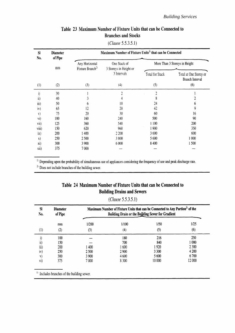
Building Services

Building Services
FIG. 13 PEAK FLOW LOAD CURVES
5D.5.5.3.5.2.2
When flow occurs in drain piping, it should not entirely fill the
cross-section of the pipe under flow condition. If the pipe were
to flow full, pressure fluctuations would occur which could
possibly destroy the seal of the traps within the building.
Normally, the sewer shall be designed for discharging the peak
flow as given in 5.5.3.5.1, flowing half-full with a minimum
self-cleansing velocity of 2.5 ft/s. The approximate gradients
which give this velocity for the sizes of pipes likely to be used
in building drainage and the corresponding discharges when
following half-full are given in Table 27.
5D.5.5.3.5.2.3
In cases where it is practically not possible to conform to the
ruling gradients, a flatter gradient may be used, but the
minimum velocity in such cases shall on no account be less
than 2 ft/s and adequate flushing should be done.
NOTE — Where gradients are restricted, the practice of using a
pipe of larger diameter than that required by the normal flow,
in order to justify laying at a flatter gradient does not result in
increasing the velocity of flow, further this reduces the depth
of flow and thus for this reasons the above mentioned practice
should be discouraged.
5D.5.5.3.5.2.4
On the other hand, it is undesirable to employ gradients giving
a velocity of flow greater than 8 ft /s. Where it is unavoidable,
cast iron pipes shall be used. The approximate gradients, which
give a velocity of 8 ft/s for pipes of various sizes and the
corresponding discharge when flowing half-full are given in
Table 27.

Building Services
5D.5.5.3.5.2.5
The discharge values corresponding to nominal diameter and
gradient given in Table 27 are based on Manning's formula (n
= 0.015).
NOTE — Subject to the minimum size of 4 inches, the sizes of
pipes shall be decided in relation to the estimated quantity of
flow and the available gradient.
Table 25 Different Dia Pipes Giving Velocity and Corresponding Discharge
at Minimum and Maximum Gradient
(Clauses 5.5.3.5.2.2, 5.5.3.5.2.4, 5.5.3.5.2.5)
SI
No.
(1)
Diameter
in
(2)
Minimum
Gradient
(Velocity:2.5 ft/s)
(3)
Discharge at the
Minimum Gradient
( ft3 /s )
(4)
Maximum
Gradient
(Velocity:8 ft/s)
(5)
Discharge at the
Maximum Gradient
( ft3/s )
(6)
i)
ii)
iii)
iv)
v)
vi)
4
6
8
9
10
12
1 in 57
1 in 100
1 in 145
1 in 175
1 in 195
1 in 250
0.11
0.25
0.43
0.55
0.65
1.00
1 in 5.6
1 in 9.7
1 in 14
1 in 17
1 in 19
1 in 24.5
0.35
0.78
1.41
1.75
2.12
3.12
5D.5.5.3.6 Drain appurtenances
5D.5.5.3.6.1 Trap
All traps shall be protected against siphonage and back pressure
ensuring access to atmospheric air for air circulation and
preserving the trap seal in all conditions.
5D.5.5.3.6.1.1
A trap may be formed as an integral trap with the appliance
during manufacture or may be a separate fitting called an attached
trap which may be connected to the waste outlet of the appliance.
5D.5.5.3.6.1.2
Traps should always be of a self-cleansing pattern. A trap,
which is not an integral part of an appliance, should be directly
attached to its outlet and the pipe should be uniform
throughout and have a smooth surface.
5D.5.5.3.6.1.3
The trap should have minimum size of outlet/exit, same as that
of largest waste inlet pipe.
Building Services
5D.5.5.3.6.1.4
Traps for use in domestic waste installations and all other traps
should be conveniently accessible and provided with cleansing
eyes or other means of cleaning.
5D.5.5.3.6.1.5
The minimum internal diameter for sanitary appliances shall be as
follows:
Sanitary Appliance Minimum Internal
Diameter of Waste
Outlet (inches)
Soil appliances
a) Indian and European type water closets 4
b) Bed pan washers and slop sinks 4
c) Urinal with integral traps 3
d) Stall urinals (with not more than 2
5 inches of channel drainage)
e) Lipped urinal small/large40 1½
Waste appliances
f) Drinking fountain 1
g) Wash basin 1¼
h) Bidets 1¼
i) Domestic sinks and baths 1½
j) Shower bath trays 1½
k) Domestic bath tubs 2
l) Hotel and canteen sinks 2
m) Floor traps (outlet diameter) 2½
5D.5.5.3.6.2 Floor drains
All toilets/bathrooms in a building desirably should be provided with
floor drains to facilitate cleaning.
5D.5.5.3.6.2.1
Floor drains shall connect into a trap so constructed that it can be
readily cleaned and of a size to serve efficiently the purpose for
which it is intended. The trap shall be either accessible from
the floor drain or by a separate cleanout within the drain.
5D.5.5.3.6.2.2
Floor drain also receives, waste piping which does not connect
to the sanitary system, known as indirect waste. This discharge

Building Services
from an indirect waste should be conveyed into a water
supplied, trapped and vented floor drain.
5D.5.5.3.6.2.3
Floor drain should be provided in mechanical equipment
rooms, where pumps, boilers, water chillers, heat exchangers
and other air conditioning equipments are periodically drained
for maintenance and repair. Boiler requires drain at safety
relief valve discharge.
5D.5.5.3.6.2.4
Strategically floor drains are required to be located in buildings
with wet fire protection sprinkler systems to drain water in
case of activation of sprinkler heads.
5D.5.5.3.6.3 Cleanouts
The cleanout provides access to horizontal and vertical lines
and stacks to facilitate inspection and means to remove
obstructions common to all piping systems, such as solid
objects, greasy wastes, hair and the like.
5D.5.5.3.6.3.1
Cleanouts in general should be gas and water-tight, provide
quick and easy plug removal, allow ample space for rodding
tools, have means of adjustments to finished floor level, be
attractive and be designed to support whatever load is directed
over them.
5D.5.5.3.6.3.2
Waste lines are normally laid beneath the floor slab at a
sufficient distance to provide adequate back-fill over the joints.
Cleanouts are then brought up to floor level grade by pipe
extension pieces.
5D.5.5.3.6.3.3
The size of the cleanout within a building should be the same
size as the piping up to 4 inches. For larger size piping 4 inches
cleanouts are adequate for their intended purpose.
5D.5.5.3.6.3.4
Cleanouts are suggested to be provided at the following
locations:
a) Inside the building at a point of exit, Y junction branch or a
trap.
b) At every change of direction greater than 450.
c) At the base of all stacks.

Building Services
d) At the horizontal header, receiving vertical stacks and serving the
purpose of offset header.
5D.5.5.4 Indirect Wastes
5D.5.5.4.1 General
Waste, overflow and drain pipes from the following types of equipment
shall not be connected into any drainage system directly to prevent
backflow from the drainage system into the equipment/installation:
a) Plumbing and kitchen appliances.
1) Underground or overhead water tanks.
2) Drinking water fountains.
3) Dishwashing sinks and culinary sinks used for soaking and
preparation of food.
4) Cooling counters for food and beverages.
5) Kitchen equipment for keeping food warm.
6) Pressure drainage connections from equipment.
b) Air conditioning, heating and other mechanical equipments
1) Air handling equipment.
2) Cooling tower and other equipments.
3) Condensate lines from equipments
4) Storage tanks.
5) Condensate lines.
6) Boiler blow down lines.
7) Steam trap drain lines.
c) Laboratories and other areas
1) Water stills.
2) Waste from laboratory in specified sinks.
3) Sterlizers and similar equipments.
4) Water purification equipments.
5D.5.5.4.2 Indirect waste receptors
All plumbing fixtures or other receptors receiving the discharge of
indirect waste pipes shall be of such shape and capacity as to prevent
splashing or flooding and shall be located where they are readily
accessible for inspection and cleaning.
5D.5.5.4.3 Pressure drainage connections
Indirect waste connections shall be provided for drains, overflows or
relief vents from the water supply system, and no piping or equipment
carrying wastes or producing wastes or other discharges under pressure
shall be directly connected to any part of the drainage system.

Building Services
The above shall not apply to any approved sump pump or to any
approved plumbing fixture discharging pressurized waste or device
when the Authority has been satisfied that the drainage system has the
capacity to carry the waste from the pressurized discharge.
5D.5.5.5 Special Wastes
5D.5.5.5.1 General
Wastes having characteristics which may be detrimental to the pipes in
which it is disposed as well as to the persons handling it. Such wastes
used in a building need to be specially identified and a suitable and safe
method of its disposal installed to ensure that the piping system is not
corroded nor the health and safety of the occupants is affected in any
way.
Whenever the occupant or the user of any wastes is unaware of the
dangers of the consequences of disposing the waste, he shall be made
aware of the dangers of his action along with providing suitable warning
and instruction for correct disposal be provided to him.
Piping system for all special wastes should be separate and independent
for each type of waste and should not be connected to the building
drainage system. Other applicable provisions for installation of soil and
waste pipe system shall be however be followed.
5D.5.5.5.2 Laboratory waste
A study of the possible chemical and corrosive and toxic properties of
wastes handled and disposed off in a laboratory need to be ascertained in
advance. The relevant statutory rules and regulation regarding the
method of disposal of strong and objectionable wastes shall be followed.
All sinks, receptacles, traps, pipes, fittings and joints shall of materials
resistant to the liquids disposed off in the system.
In laboratories for educational, research and medical institutions,
handling mildly corrosive and toxic wastes, they may be neutralized in
chambers using appropriate neutralizing agents. The chamber shall be
provided with chambers at inlet and outlet for collecting samples of the
incoming and outgoing waste for monitoring its characteristics.
5D.5.5.5.3 Infected wastes
Infected liquid wastes are generated in hospitals from patient excreta;
operation theatres; laboratories testing samples of stools, urine, blood,
flesh; etc which shall not be disposed off into the drainage system. Such
waste shall be collected separately and pre-treated before disposal into
the building drainage system.
Soiled and linen from infectious patients needs to be collected from the
respective areas of the hospital in separate linen bins and pre-washed and
sterilized in the laundry before final wash in the hospital laundry. Liquid
wastes from the washing operations shall be neutralized to prevent any
cross contamination before disposal in the building's drainage system.
Building Services
5D.5.5.5.4 Research laboratory wastes
Research laboratories conducting research in all areas of science and
technology, for example chemical industry, pharmacy, metallurgy,
bio-sciences, agriculture, atomic energy, medicine, etc, shall follow the
established procedures laid down by statutory bodies to handle, treat and
dispose wastes which are highly toxic, corrosive, infectious,
inflammable, explosive and having bacterial cultures, complex organic
and inorganic chemicals. Such wastes shall not be disposed off in a
building drainage system or the city sewerage system unless they are
pre-treated and meet the disposal criteria in accordance with the relevant
rules/regulations.
5D.5.5.6 Grease Traps
Oil and grease is found in wastes generated from kitchens in hotels, industrial
canteens, restaurant, butcheries, some laboratories and manufacturing units
having a high content of oil and greases in their final waste.
Waste exceeding temperature of 60° C should not be allowed in the grease trap.
When so encountered it may be allowed to cool in a holding chamber before
entering the grease trap.
Oil and greases tend to solidify as they cool within the drainage system. The
solidified matter clogs the drains and the other matter in the waste stick to it due
to the adhesion properties of the grease. Oil and greases are lighter than water
and tend to float on the top of the waste water.
Grease traps shall be installed in building having the above types of wastes. In
principle the grease laden water is allowed to retain in a grease trap which
enables any solids to be settled or separated for manual disposal. The retention
time allows the incoming waste to cool and allow the grease to solidify. The
clear waste is then allowed to discharge into the building's drainage system.
5D.5.5.7 Oil Interceptors
Oils and lubricants are found in wastes from vehicle service stations,
workshops manufacturing units whose waste may contain high content of oils.
Oils, for example, petroleum, kerosene and diesel used as fuel, cooking,
lubricant oils and similar liquids are lighter than water and thus float on water in
a pipe line or in a chamber when stored. Such oils have a low ignition point and
are prone to catch fire if exposed to any flame or a spark and may cause
explosion inside or outside the drainage system. The flames from such a fire
spread rapidly if not confined or prevented at the possible source. Lighter oils
and lubricants are removed from the system by passing them through an oil
interceptor/petrol gully. They are chambers in various compartments which
allow the solids to settle and allow the oils to float to the top. The oil is then
decanted in separate containers for disposal in an approved manner. The oil free
waste collected from the bottom of the chamber is disposed in the building
drainage system.
5D.5.5.8 Radioactive Waste
Scientific research institutions, hospital and many types of manufacturing
processes use radioactive material in form of radio isotopes and other

Building Services
radioactive sources for their activities. Manufacture, sale, use and disposal of
radioactive material is regulated by the statutory rules and regulation. Proposal
for usage and disposal of radioactive materials shall be done in consultation
with and prior permission of the Authority by the users of the materials. No
radioactive material shall be disposed off in any building drainage system
without the authorization of the Authority.
5D.5.5.9 Special Situations of Waste Water Disposal
Buildings may generate uncontaminated waste water from various sources
continuously, intermittently or in large volumes for a short time, for example,
emptying any water tanks or pools, testing fire and water lines for flow
conditions, etc. Connections from all such sources shall be made to the building
drainage system indirectly through a trap. It should be ensured in advance that
the building drain or a sump with a pump has the capacity to receive to rate of
flow. In case the capacity is less the rate of discharge from the appliances
should be regulated to meet the capacity of the disposal. Under no
circumstances shall any waste water described above shall be disposed off in
any storm water drains.
5D.5.5.10 Manholes
5D.5.5.10.1 General
A manhole or inspection chamber shall be capable of sustaining the loads
which may be imposed on it, exclude sub-soil water and be water-tight.
The size of the chamber should be sufficient to permit ready access to the
drain or sewer for inspection, cleaning and rodding and should have a
removable cover of adequate strength, constructed of suitable and
durable material. Where the depth of the chamber so requires, access
rungs, step irons, ladders or other means should be provided to ensure
safe access to the level of the drain or sewer. If the chamber contains an
open channel, benching should be provided having a smooth finish and
formed so as to allow the foul matter to flow towards the pipe and also
ensure a safe foothold.
No manhole or inspection chamber shall be permitted inside a building
or in any passage therein. Further, ventilating covers shall not be used for
domestic drains. At every change of alignment, gradient or diameter of a
drain, there shall be a manhole or inspection chamber. Bends and
junctions in the drains shall be grouped together in manholes as far as
possible.
5D.5.5.10.2 Maximum Spacing of manhole
The maximum spacing of manholes for a given pipe size should be as
follows:
Pipe Diameter Maximum Spacing of
Manhole
inches feet
Up to 6 50
> 6 to 12 100
Building Services
>12 to 18 150
>18 to 36 250
Beyond 36 300 or spacing shall
depend upon local condition and shall be
gotten approved by the Authority
Where the diameter of a drain is increased, the crown of the pipes shall
be fixed at the same level and the necessary slope given in the invert of
the manhole chamber. In exceptional cases and where unavoidable, the
crown of the branch sewer may be fixed at a lower level, but in such
cases the peak flow level of the two sewers shall be kept the same.
5D.5.5.10.3 Size of manhole
The manhole or chamber shall be of such size as will allow necessary
examination or clearance of drains. The size of manhole shall be adjusted
to take into account any increase in the number of entries into the
chamber.
5D.5.5.10.3.1
Manholes may be rectangular, arch or circular type. The minimum
internal size of manholes, chambers (between faces of masonry)
shall be as follows:
a) Rectangular Manholes
(1) For depths less than 3 feet 3 feet x 2 feet 8 inches
(2) For depths from 3 feet and up to 8 feet 4 feet x 3 feet
b) Arch Type Manholes
a) For depths of 8 feet and above 4 feet 6 inches x 3 feet
NOTE—The width of manhole chamber shall be suitably increased
more than 3feet on bends, junctions or pipes with diameter greater
than 1 feet 6 inches so that benching width in either side of
channel is minimum 8 inches.
c) Circular Manholes
1) For depths above 3 feet and up to 5 feet 6 inches
3 feet - diameter
2) For depths above 5 feet 6 inches and up to 7 feet 6
inches 4 feet - diameter
3) For depths above 7 feet 6 inches and up to 29 feet 6
inches 5 feet - diameter
4) For depths above 29 feet 6 inches and up to 46 feet
6 feet – diameter
NOTES
1 In adopting the above sizes of chambers, it should
be ensured that these sizes accord with full or half bricks with

Building Services
standard thickness of mortar joints so as to avoid wasteful cutting
of bricks.
2 The sizes of the chambers may be adjusted to suit
the availability of local building materials and economics of
construction.
3 The access shaft shall be corbelled inwards on
three sides at the top to reduce its size to that of the cover frame to
be fitted or alternatively the access shaft shall be covered over by a
reinforced concrete slab of suitable dimensions with an opening
for manhole cover and frame.
5D.5.5.10.4 Construction
5D.5.5.10.4.1 Excavation
The manhole shall be excavated true to dimensions and levels as
shown on the plan. The excavation of deep manholes shall be
accompanied with safety measures like timbering, staging, etc. In
areas where necessary, appropriate measures for dewatering
should be made.
5D.5.5.10.4.2 Bed Concrete
The manhole shall be built on a bed of concrete 1:4:8 (1 cement: 4
coarse sand: 8 graded stone aggregate 1½ in nominal size). The
thickness of bed concrete shall be at least 6 in for manholes up to 3
feet in depth, at least 8 inches for manholes from 3 feet upto 8 feet
in depth and at least 1 ft for manholes of greater depth, unless the
structural design demands higher thickness.
This thickness may be verified considering the weight of wall,
cover, the wheel loads, impact of traffic which are transmitted
through cover and the shaft walls and for water pressure, if any. In
case of weak soil, special foundation as suitable shall be provided.
5D.5.5.10.4.3 Brickwork
The thickness of walls shall be designed depending upon its shape
and taking onto account all loads coming over it, including earth
pressure and water pressure.
Generally the brickwork shall be with first class bricks in cement
mortar 1:5 (1 cement: 5 coarse sand). All brickwork in manhole
chambers and shafts shall be carefully built in English Bond, the
jointing faces of each brick being well "buttered" with cement
mortar before laying, so as to ensure a full joint. The construction
of walls in brickwork shall be done in accordance with good
practice [9-1(26)].
For various depths the recommended thickness of wall may be as
follows:

Building Services
Depth of the Chamber Thickness of Wall
a) Up to 7 feet 6 inches 8 inches (one brick
length)
b) From 7 feet 6 inches up to 10 feet 1 feet (one and half brick
length)
c) From 10 feet up to 16 feet 6 inches 1 feet 4 inches (two
brick length)
d) From 16 feet 6 inches up
to 29 feet 6 inches 1 feet 8 inches
(two and half brick length)
e) Above 29 feet 6 inches 2 feet (three brick
length)
The actual thickness in any case shall be calculated on the basis of
engineering design. Typical sections of the manholes are illustrated
in Fig. 14, 15 and 16.
NOTES
1 Rich mix of cement mortar, not weaker than 1:3,
should be used in brick masonry, where sub-soil
water conditions are encountered.
2 For arched type of manholes, the brick masonry in
arches and arching over pipes shall be in cement
mortar 1:3.
FIG. 14 DETAIL OF MANHOLE (DEPTH LESS THAN 3 FEET)

Building Services
FIG. 15 DETAIL OF MANHOLE ( DEPTH 3 FEET AND UP TO 8 FEET )
5D.5.5.10.4.4 Plastering
The wall shall be plastered (½ inches, Min) both inside and outside
within cement mortar 1:3 and finished smooth with a coat of neat
cement. Where sub-soil water conditions exist, a richer mix may
be used and it shall further waterproofed with addition of
approved waterproofing compound in a quantity as per
manufacturer specifications.
All manholes shall be so constructed as to be watertight under test.
All angles shall be rounded to 3 inches radius and all rendered
internal surface shall have hard impervious finish obtained using a
steel trowel.
5D.5.5.10.4.5 Channels and benching
These shall be semi-circular in the bottom half and of diameter
equal to that of the sewer. Above the horizontal diameter, the sides
shall be extended vertically 2 inches above the crown of sewer
pipe and the top edge shall be suitably rounded off. The branch
channels shall also be similarly constructed with respect to the
benching, but at their junction with the main channel an
appropriate fall, if required suitably rounded off in the direction of
flow in the main channel shall be given.
The channel/drain and benching at the bottom of the chamber
shall be done in cement concrete 1:2:4 and subsequently plastered
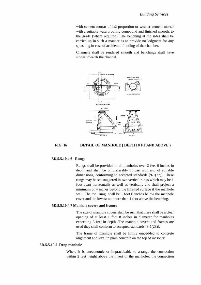
Building Services
with cement mortar of 1:2 proportion or weaker cement mortar
with a suitable waterproofing compound and finished smooth, to
the grade (where required). The benching at the sides shall be
carried up in such a manner as to provide no lodgment for any
splashing in case of accidental flooding of the chamber.
Channels shall be rendered smooth and benchings shall have
slopes towards the channel.
FIG. 16 DETAIL OF MANHOLE ( DEPTH 8 FT AND ABOVE )
5D.5.5.10.4.6 Rungs
Rungs shall be provided in all manholes over 2 feet 6 inches in
depth and shall be of preferably of cast iron and of suitable
dimensions, conforming to accepted standards [9-1(27)]. These
rungs may be set staggered in two vertical rungs which may be 1
foot apart horizontally as well as vertically and shall project a
minimum of 4 inches beyond the finished surface if the manhole
wall. The top rung shall be 1 foot 6 inches below the manhole
cover and the lowest not more than 1 foot above the benching.
5D.5.5.10.4.7 Manhole covers and frames
The size of manhole covers shall be such that there shall be a clear
opening of at least 1 foot 8 inches in diameter for manholes
exceeding 3 feet in depth. The manhole covers and frames are
used they shall conform to accepted standards [9-1(28)].
The frame of manhole shall be firmly embedded to concrete
alignment and level in plain concrete on the top of masonry.
5D.5.5.10.5 Drop manhole
Where it is uneconomic or impracticable to arrange the connection
within 2 feet height above the invert of the manholes, the connection

Building Services
shall be made by constructing a vertical shaft outside the manhole
chamber, as shown in Fig. 17. If the difference in level between the
incoming drain and the sewer does not exceed 2 feet, and there is
sufficient room in the manhole, the connecting pipe may be directly
brought through the manhole wall and the fall accommodated by
constructing a ramp in the benching of the manhole.
For detailed information regarding manholes in sewerage system,
reference may be made to good practice [9-1(29)].
FIG. 17 DROP MANHOLE
NOTE – Wall thickness have been indicated in brick length to provide
for use of modular bricks or traditional bricks. In the Fig. B = one brick
length, 1.5B = one and a half brick length etc.
5D.5.5.11 Storm Water Drainage
5D.5.5.11.1 General
The object of storm water drainage is to collect and carry, the rain-water
collected within the premises of the building, for suitable disposal.
5D.5.5.11.2 Design factors
Estimate of the quantity that reaches the storm water drain depends on the
following factors:
a) Type of soil and its absorption capacity determined by its soil group.
b) Ground slope and the time in which the area is drained.
c) Intensity of the rainfall for a design period.
d) Duration of the rain/storm.
1 ft 6
in

Building Services
5D.5.5.11.2.1 Imperviousness
The soil conditions and the ground slope determine the
impermeability factor. Impermeability factor is the proportion of
the total rainfall received on the surface which will be discharging
into the a storm water drain after allowing for initial abstraction
(in local pond and lakes), ground absorption by evaporation,
vegetation and other losses. The net flow reaching the storm water
drain is called runoff.
The percentage of imperviousness of the drainage area may be
obtained from available data for a particular area. In the absence
of such data, the following values may serve as a guide:
Type of area Imperviousness
factor(percent)
Commercial and industrial areas 70-90
Residential areas (high density) 60-75
Residential areas (low density) 35-60
Parks and underdeveloped areas 10-20
5D.5.5.11.2.2 Terrain modeling
Areas planned for urbanization from agricultural land, forest or
low grade land for example, low lying areas prone to flooding,
marshy or abandoned quarries, etc need detailed and careful
consideration with respect to its drainage. A detailed contour
survey shall be carried out not only with respect to the site but also
the surrounding areas to verify the quantity/area contributing
runoff, presence of any low lying and natural water body acting as
holding pond or any natural drain passing through the area and
beyond whose filling up or diversion may cause water logging
problem on the site or to the surrounding areas.
The planning of the area should ensure that:
a) All areas become self draining by gravity with respect to the high
flood level of the area or the drainage channels passing whichever
is higher.
b) As far as possible, natural drainage pattern with respect to the
whole area be maintained except when low lying areas need to be
filled up for grading purposes.
c) The drainage in the area shall be planned in accordance with the
natural slopes.
d) Levels of the main highway or road connecting to the property
shall be determined to ensure proper drainage and protection of
the site.

Building Services
e) The formation levels of the entire area shall be prepared to
determine proposed formation levels by preparing a terrain model
which will show the proposed the site contours, ground and road
levels and connections to all services including storm water
disposal system.
5D.5.5.11.2.3 Design frequency
Storm water drainage system for an urbanized area is planned on
the basis of the design frequency of the storm which shall be
determined by the designer. Frequency is the period in which the
selected design intensity recurs in a given period of time in years.
5D.5.5.11.2.4 Time of concentration
Time of concentration is the time required for the rainwater to
flow to reach the farthest point of the drainage system or the
outfall under consideration. Time of concentration is equal to the
inlet time plus the time required for the flow to reach the main or
branch drain. The inlet time is the time dependent on the distance
of the farthest point in the drainage area to the inlet of the manhole
and the surface slopes, etc and will vary between 5 min to 30 min.
In highly developed sections for example with impervious
surfaces it may be as low as 3 min or lower (with good slopes) as
in building terraces and paved areas. Correspondingly the design
intensity for the drainage for such areas will be much higher.
Rainwater pipes have to be designed for an intensity for a very low
time of concentration.
5D.5.5.11.2.5 Natural infiltration
In planning any area with buildings, layout with paved and
non-permeable surfaces, care should be taken to allow maximum
discharge of the rain-water to flow directly or indirectly to
permeate into the ground for enabling the ground water to be
recharged. Some of the techniques which allow infiltration that
may be considered are:
a) Use of brick paved open jointed storm water drains.
b) Providing bore holes in the storm water drains.
c) Using paving tiles with open joints which enable water to percolates as it
flows on it.
5D.5.5.11.3 Combined system
A combined system of drainage is one which carries the sewerage as well
as the runoff from the storm water drainage. Relevant applicable
statutory rules/ regulations may not allow such system in new areas and
the sewerage and the storm water drainage have to be separate and
independent of each other. Such systems are however existing in many
old cities and the storm water may have to be discharged into the
combined drainage system.

Building Services
Where levels do not permit for connection to a public storm water drain,
storm water from courtyards of buildings may be connected to the public
sewer, provided it is designed to or has the capacity to convey combined
discharge. In such cases, the surface water shall be admitted to the soil
sewer through trapped gullies in order to prevent the escape of foul air.
5D.5.5.11.4 Discharging into a watercourse
It may often be convenient to discharge surface water to a nearby stream
or a watercourse. The invert level of the outfall shall be about the same as
the normal water level in the watercourse or ideally should be above the
highest flood level of the watercourse. The out-fall shall be protected
against floating debris by a screen.
5D.5.5.11.5 Discharge to a public storm water drain
Where it is necessary to connect the discharge rainwater into a public
storm water drain, such drains shall be designed for the intensity of rain
based on local conditions, but in no case shall they be designed for
intensity of rainfall of less than 2 inches / hour. Rainwater from each
building plot shall be connected to the storm water drainage through a
separate pipe or an open public drain directly. No trap shall be installed
before the connection.
5D.5.5.11.6 Rain-water pipes for roof drainage
5D.5.5.11.6.1
The roofs of a building shall be so constructed or framed as to permit
effectual drainage of the rain-water there from by means of a
sufficient number of rain-water pipes of adequate size so arranged,
jointed and fixed as to ensure that the rainwater is carried away from
the building without causing dampness in any part of the walls or
foundations of the building or those of an adjacent building.
5D.5.5.11.6.2
The rain-water pipes shall be fixed to the outside of the external walls
of the building or in recesses or chases cut or formed in such external
wall or in such other manner as may be approved by the Authority.
5D.5.5.11.6.3
Rain-water pipes conveying rain- water shall discharge directly or
by means of a channel into or over an inlet to a surface drain or
shall discharge freely in a compound, drained to surface drain but
in no case shall it discharge directly into any closed drain.
5D.5.5.11.6.4
Whenever it is not possible to discharge a rain-water pipe into or
over an inlet to a surface drain or in a compound or in a street drain
within 100 ft from the boundary of the premises, such rain-water
pipe shall discharge into a gully trap which shall be connected
with the street drain for storm water and such a gully- trap shall
have a screen and a silt catcher incorporated in its design.

Building Services
5D.5.5.11.6.5
If such streets drain is not available within 100ft of the boundary
of the premises, a rain-water pipe may discharge directly into the
kerb drain and shall be taken through a pipe outlet across the foot
path, if any, without obstructing the path.
5D.5.5.11.6.6
A rain water pipe shall not discharge into or connect with any soil
pipe or its ventilating pipe or any waste pipe or its ventilating pipe
nor shall it discharge into a sewer unless specifically permitted to
do so by the Authority, in which case such discharge into a sewer
shall be intercepted by means of a gully trap.
5D.5.5.11.6.7
Rain-water pipes shall be constructed of cast iron, PVC, asbestos
cement, galvanized sheet or other equally suitable material and
shall be securely fixed.
5D.5.5.11.6.8
The factors that decide the quantity of rain water entering are:
a) Intensity of rainfall, and
b) Time of concentration selected for rain-water pipe.
A bell mouth inlet at the roof surface is found to give better
drainage effect, provided proper slopes are given to the roof
surface. The spacing of rain-water pipes depends on the locations
available for the down takes and the area which each pipe serves.
The spacing will also be determined by the amount of slopes that
can be given to the roof. The recommended slopes for the flat
roofs with smooth finish would be 1:150 to 1:133, with rough
stone/tiles 1:100 and for gravel set in cement or losely packed
concrete finish 1:75 to 1:66. The effective strainer area should
preferably be 1.5 to 2 times the area of pipe to which it connects to
considerably enhance the capacity of rain water pipes.
The rain water pipes of cast iron (coefficient of roughness 0.013)
shall normally be sized on the basis of roof areas according to
Table 28. The vertical down take rain-water pipes, having a bell
mouth inlet on the roof surface with effective cross-sectional area
of grating 1.5 to 2 times the rain-water pipe area, may be designed
by considering the outlet pipe as weir.
For full circumference of pipe acting as weir, the roof area (RA)
for drainage may be worked out by using RA = 0.084 x d 5/2
/I
Where d = Pipe diameter; inches
I = Intensity of rainfall ( inches / hour )

Building Services
Table 26 Sizing of Rain-Water Pipes for Roof Drainage
( Clause 5.5.11..6.8)
Dia of Pipe
(in)
Average Rate of Rainfall
( inches / hour )
2 3 4 5 6 7
Roof Area ( ft2 )
2 144.24 95.80 71.04 57.05 47.36 35.52
2½ 259.41 172.23 129.17 103.33 86.11 64.58
3 439.17 290.63 219.59 175.45 146.39 109.79
4 919.25 613.55 459.62 368.13 306.77 229.27
5 1719.12 1148.84 866.50 692.13 575.87 430.56
6 2686.69 1795.65 1348.41 107.64 899.87 674.90
NOTE – For rain-water pipes of other materials, the roof areas shall
be multiplied by (0.013/coefficient of roughness of surface of that
material).
5D.5.5.11.6.9
The storm water may be led off in a suitable open drain to a
watercourse. The open drain, if not a pucca masonry throughout,
shall be so at least where there is either a change in direction or
gradient.
5D.5.5.12 Rain-water Harvesting
5D.5.5.12.1 General
To supplement the ever growing shortage of protected, pure and safe
water supply for human consumption rainwater is an ideal source which
can be conserved and used in a useful manner by the people. The amount
of rainfall available varies from region to region. Each area has to
develop its own method and system to conserve, store and use it to suit
its requirements and local conditions. There are several methods by
which rain-water can be stored, used and conserved. Each system
depends on the amount of precipitation, the period in which the rainfall
occurs in a year and the physical infrastructure for example, space
available to store the water, etc.
There are several techniques available for catching and storing the
rain-water. Most of the techniques are applicable for large open areas,
farms, sloping grounds etc, with a low population base. Two major
systems that are ideal for urban and semi-urban developed areas are:
a) Artificial ground water recharge, and
b) Roof top rain-water harvesting.
5D.5.5.12.2 Artificial ground water recharge
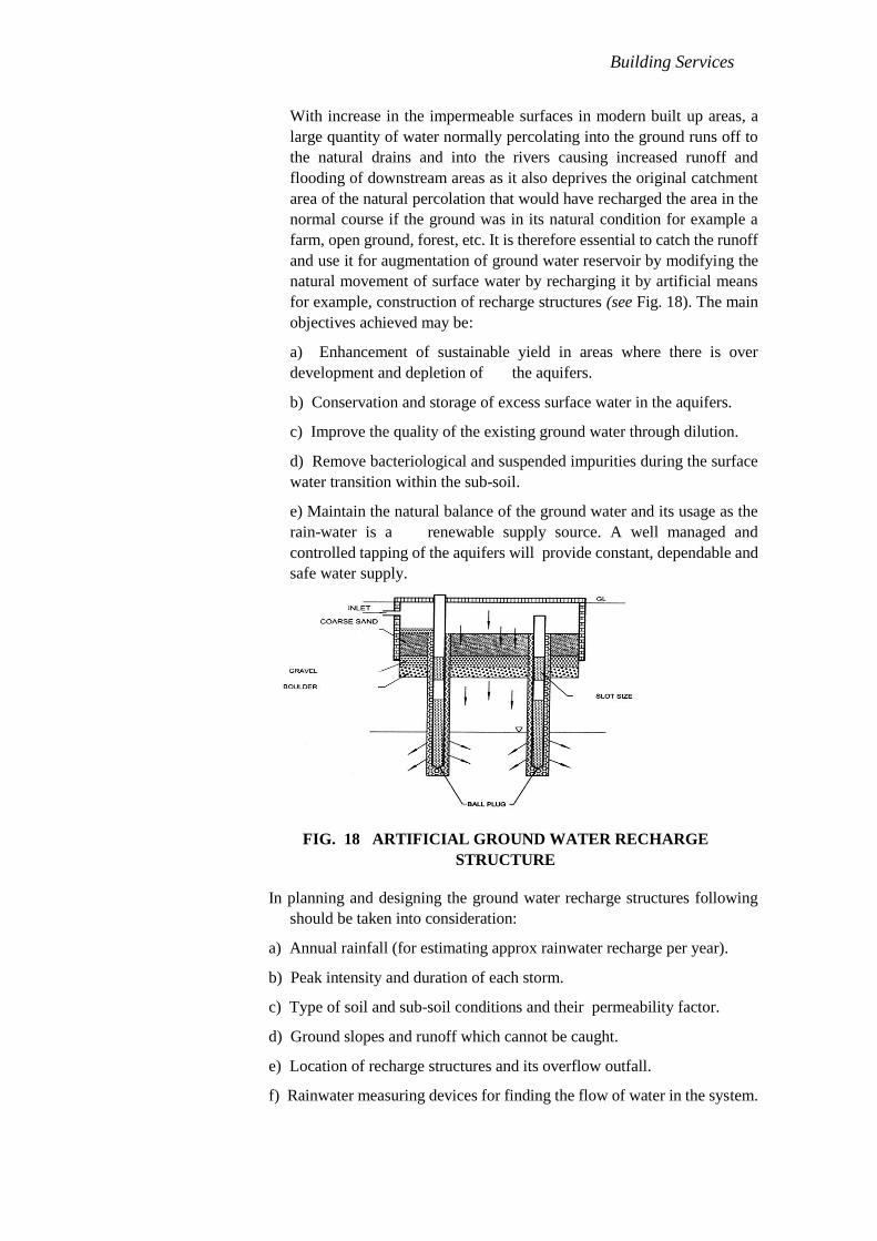
Building Services
With increase in the impermeable surfaces in modern built up areas, a
large quantity of water normally percolating into the ground runs off to
the natural drains and into the rivers causing increased runoff and
flooding of downstream areas as it also deprives the original catchment
area of the natural percolation that would have recharged the area in the
normal course if the ground was in its natural condition for example a
farm, open ground, forest, etc. It is therefore essential to catch the runoff
and use it for augmentation of ground water reservoir by modifying the
natural movement of surface water by recharging it by artificial means
for example, construction of recharge structures (see Fig. 18). The main
objectives achieved may be:
a) Enhancement of sustainable yield in areas where there is over
development and depletion of the aquifers.
b) Conservation and storage of excess surface water in the aquifers.
c) Improve the quality of the existing ground water through dilution.
d) Remove bacteriological and suspended impurities during the surface
water transition within the sub-soil.
e) Maintain the natural balance of the ground water and its usage as the
rain-water is a renewable supply source. A well managed and
controlled tapping of the aquifers will provide constant, dependable and
safe water supply.
In planning and designing the ground water recharge structures following
should be taken into consideration:
a) Annual rainfall (for estimating approx rainwater recharge per year).
b) Peak intensity and duration of each storm.
c) Type of soil and sub-soil conditions and their permeability factor.
d) Ground slopes and runoff which cannot be caught.
e) Location of recharge structures and its overflow outfall.
f) Rainwater measuring devices for finding the flow of water in the system.
1/32 to
3/32 in
3/16 to
3/8 in
3/16 to
3/4 in
⅛
in
FIG. 18 ARTIFICIAL GROUND WATER RECHARGE
STRUCTURE

Building Services
For artificial recharge to ground water, Guidelines for Artificial Recharge to
Ground Water (under preparation) may be referred.
5D.5.5.12.3 Roof top rain-water harvesting
5D.5.5.12.3.1 Harvesting in regular rainfall areas
In areas having rainfall over a large period in a year for example,
in hilly areas and coastal regions, constant and regular rainfall can
be usefully harvested and stored in suitable water tanks. Water is
collected through roof gutters and down take pipes. Provision
should be made to divert the first rainfall after a dry spell so that
any dust, soot, leaves etc, are drained away before the water is
collected into the water tank. The capacity of the water tank
should be enough for storing water required for consumption
between two dry spells. The water tank shall be located in a well
protected area and should not be exposed to any hazards of water
contamination from any other sources. The water shall be
chlorinated using chlorine tablets or solution to maintain a
residual chlorine of approximately 1 ppm. The tank must have an
overflow leading to a natural water courses or to any additional
tanks (see Table 29).
Table 27 Rainwater Available from Roof Top Harvesting
( Clause 5.5.12.13.1 )
Rain Fall
(inch) 3 6 9 12 15 18 21 24 27 30 33 36 39 42 45 48 51 54 57 60
Roof Top
Area (ft2) Harvested Water from Roof Tops ( x 103 ft3 )
( 80 percent of gross precipitation )
100 0.02 0.04 0.06 0.08 0.1 0.12 0.14 0.16 0.18 0.2 0.22 0.24 0.26 0.28 0.3 0.32 0.34 0.36 0.38 0.4
200 0.04 0.08 0.12 0.16 0.2 0.24 0.28 0.32 0.36 0.4 0.44 0.48 0.52 0.56 0.6 0.64 0.68 0.72 0.76 0.8
300 0.06 0.12 0.18 0.24 0.3 0.36 0.42 0.48 0.54 0.6 0.66 0.72 0.78 0.84 0.9 0.96 1.02 1.08 1.14 1.2
400 0.08 0.16 0.24 0.32 0.4 0.48 0.56 0.64 0.72 0.8 0.88 0.96 1.04 1.12 1.2 1.28 1.36 1.44 1.52 1.6
500 0.1 0.2 0.3 0.4 0.5 0.6 0.7 0.8 0.9 1 1.1 1.2 1.3 1.4 1.5 1.6 1.7 1.8 1.9 2
600 0.12 0.24 0.36 0.48 0.6 0.72 0.84 0.96 1.08 1.2 1.32 1.44 1.56 1.68 1.8 1.92 2.04 2.16 2.28 2.4
700 0.14 0.28 0.42 0.56 0.7 0.84 0.98 1.12 1.26 1.4 1.54 1.68 1.82 1.96 2.1 2.24 2.38 2.52 2.66 2.8
800 0.16 0.32 0.48 0.64 0.8 0.96 1.12 1.28 1.44 1.6 1.76 1.92 2.08 2.24 2.4 2.56 2.72 2.88 3.04 3.2
900 0.18 0.36 0.54 0.72 0.9 1.08 1.26 1.44 1.62 1.8 1.98 2.16 2.34 2.52 2.7 2.88 3.06 3.24 3.42 3.6
1000 0.2 0.4 0.6 0.8 1 1.2 1.4 1.6 1.8 2 2.2 2.4 2.6 2.8 3 3.2 3.4 3.6 3.8 4
1100 0.22 0.44 0.66 0.88 1.1 1.32 1.54 1.76 1.98 2.2 2.42 2.64 2.86 3.08 3.3 3.52 3.74 3.96 4.18 4.4
1200 0.24 0.48 0.72 0.96 1.2 1.44 1.68 1.92 2.16 2.4 2.64 2.88 3.12 3.36 3.6 3.84 4.08 4.32 4.56 4.8
1300 0.26 0.52 0.78 1.04 1.3 1.56 1.82 2.08 2.34 2.6 2.86 3.12 3.38 3.64 3.9 4.16 4.42 4.68 4.94 5.2
1400 0.28 0.56 0.84 1.12 1.4 1.68 1.96 2.24 2.52 2.8 3.08 3.36 3.64 3.92 4.2 4.48 4.76 5.04 5.32 5.6
1500 0.3 0.6 0.9 1.2 1.5 1.8 2.1 2.4 2.7 3 3.3 3.6 3.9 4.2 4.5 4.8 5.1 5.4 5.7 6
2000 0.4 0.8 1.2 1.6 2 2.4 2.8 3.2 3.6 4 4.4 4.8 5.2 5.6 6 6.4 6.8 7.2 7.6 8
2500 0.5 1 1.5 2.0 2.5 3 3.5 4 4.5 5 5.5 6 6.5 7 7.5 8 8.5 9 9.5 10
3000 0.6 1.2 1.8 2.4 3 3.6 4.2 4.8 5.4 6 6.6 7.2 7.8 8.4 9 9.6 10.2 10.8 11.4 12
4000 0.8 1.6 2.4 3.2 4 4.8 5.6 6.4 7.2 8 8.8 9.6 10.4 11.2 12 12.8 13.6 14.4 15.2 16
5000 1 2 3 4 5 6 7 8 9 10 11 12 13 14 15 16 17 18 19 20
10000 2 4 6 8 10 12 14 16 18 20 22 24 26 28 30 32 34 36 38 40
20000 4 8 12 16 20 24 28 32 36 40 44 48 52 56 60 64 68 72 76 80
30000 6 12 18 24 30 36 42 48 54 60 66 72 78 84 90 96 102 108 114 120
Building Services
5D.5.5.12.3.2 Harvesting in urban areas
In urban areas with the rainfall limited during the monsoon period
(usually from 15-90 days) roof top rain-water cannot be stored and
used as mentioned above and is best used for recharging the
ground water. For individual properties and plots the roof top rain-
water should be diverted to existing open or abandoned tube wells.
In a well building complex the system should be laid out so that
the runoff is discharged in bore-wells as per designs specified by
the Authority.
For roof top rain water harvesting in hilly areas reference may be
made to good practice [9-1(30)].
5D.5.5.12.4 Care to taken in rain-water harvesting
Water conservation technique discussed above shall be constructed with
due care taking following precautions:
a) No sewage or waste water should be admitted into the system.
b) No waste water from areas likely to have oil, grease or other
pollutants should be connected to the system.
c) Each structure/well shall have an inlet chamber with a silt trap to
prevent any silt from finding its way into the sub-soil water.
d) The wells should be terminated at least 16 feet 6 inches above the
natural static sub-soil water at its highest level so that the incoming
flow passes through the natural ground condition and
prevents contamination hazards.
e) No recharge structure or a well shall be used for drawing water for
any purpose.
5D.5.5.13 Sub-soil Water Drainage
5D.5.5.13.1 General
Sub-soil water is that portion of the rainfall which is absorbed into the
ground.
The drainage of sub-soil water may be necessary for the following reasons:
a) to avoid surface flooding;
b) to alleviate or to avoid causing dampness in the building, especially in
the cellars;
c) to reduce the humidity in the immediate vicinity of the building; and
d) to increase the workability of the soil.
5D.5.5.13.2 Depth of water table
The standing level of the sub-soil water will vary with the season, the
amount of rainfall and the proximity and level of drainage channels.
Information regarding this level may be obtained by means of boreholes
or trial pits, preferably the latter. It is desirable though not always
practicable to ascertain the level of the standing water over a

Building Services
considerable period so as to enable the seasonal variations to be recorded
and in particular the high water level. The direction of flow of the
sub-soil water may usually be judged by the general inclination of the
land surface and the main lines of the subsoil drains shall follow the
natural falls, wherever possible.
5D.5.5.13.3 Precautions
Sub-soil drains shall be so sited as not to endanger the stability of the
buildings or earthwork. In some portions of the drain, it may be
necessary to use non-porous jointed pipes.
5D.5.5.13.3.1
No field pipe shall be laid in such a manner or in such a position
as to communicate directly with any drain constructed or adopted
to be used for conveying sewage, except where absolutely
unavoidable and in such case a suitable efficient trap shall be
provided between sub-soil drain and such sewer.
5D.5.5.13.4 Systems of sub-soil drainage
Clay or concrete porous field drain pipes may be used and shall be laid in
one of the following ways (see also Fig, 19):
a) Natural — The pipes are laid to follow the natural depressions or
valleys of the site; branches discharge into the main as tributaries do into
a river.
b) Herringbone — The system consists of a number of drains into
which discharges from both sides smaller subsidiary branch drains
parallel to each other, but an angle to the mains forming a series of
herringbone pattern. Normally these branch drains should not exceed
30 m in length.
c) Grid — A main or mains drain is laid to the boundaries if the site into
which subsidiary branches discharge from one side only.
d) Fan-Shaper—The drains are laid converging to a single outlet at one
point on the boundary of a site, without the use of main or collecting
drains.
e) Moat or cut-off system — This system consists of drains laid on one
or more sides of a building to intercept the flow of subsoil water and
carry it away, thereby protecting the foundations of a building.

Building Services
FIG. 19 DETAILS OF DRAINAGE SYSTEM
The choice of one or more of these systems will naturally depend on the
local conditions of the site. For building sites, the mains shall be not less
than 3 inches in diameter and the branches not less than 2½ inches in
diameter and the branches not less than 2½ inches in diameter but
normal practice tends towards the use of 4 inches and 3 inches
respectively. The pipes shall generally be laid at 2 feet to 3 feet depth, or
to such a depth to which it is desirable to lower the water- table and the
gradients are determined rather by the fall of the land than by
considerations of self-cleansing velocity. The connection of the
subsidiary drain to the main drain is best made by means of a clay ware
or concrete junction pipe. The outlet of a sub-soil system may discharge
into a soak away or through a catch pit into the nearest ditch or
watercourse. Where these are not available, the sub-soil drains may be
connected, with the approval of the Authority, through an intercepting
trap to the surface water drainage system,
NOTE — Care shall be taken that there is no backflow from sub-surface
drains during heavy rains.
5D.5.5.14 Waste Disposal Systems in High Altitudes and or Sub-zero Temperature
Regions
5D.5.5.14.1
In general, all the cases to be exercised regarding water supply systems
shall also be applicable in the case of waste disposal systems shall also
be applicable in the case of waste disposal systems. The biological and
chemical reduction of organic material proceeds slowly under low
temperature conditions, consequently affecting the waste disposal
systems. The waste disposal methods given in 5.5.14.2, 5.5.14.3 and
5.5.14.4 shall be used only where it is not practical to install water
carriage system.

Building Services
5D.5.5.14.2 Box and can system
Where box and can systems are employed, adequate arrangements shall
be made for the cleaning and disinfection of the can after it is emptied of
its contents. The excrement from the can shall be disposed of by burial in
isolated spots far from habitation or by incineration, where feasible. The
can shall be fitted with a tight fitting lid for use when it is carried for
emptying.
5D.5.5.14.3 Trench or pit latrines
Trench or pit latrines shall be used only where soil and sub-soil
conditions favour their use. Whenever they are used, they shall not be
closer than 60 ft from any source of drinking water, such as well, to
eliminate the possibility of bacterial pollution of water.
5D.5.5.14.4 Chemical toilets
For the successful functioning of chemical toilets, they shall preferably
be installed in heated rooms or enclosures.
NOTE — Chemical toilet essentially consists of small cylindrical tanks
with a water-closet seat for the use of 8 to 10 persons. A ventilation pipe
is fitted to the seat. A strong solution of caustic soda is used as a
disinfectant. It kills bacteria, liquefies the solids and thus checks the
decomposition of organic matter. The tank is provided with a drain plug
for which liquid runs to a soak pit at the time of disposal.
5D.5.5.14.5 Water-borne sanitation systems
Water-borne sanitation systems shall be used, where practicable.
Sanitation systems for the collection of sewage should be constructed in
such a manner that maximum heat is retained by insulation, if necessary.
5D.5.5.14.5.1 Sewerage laying
Under normal circumstances, sewers shall be laid below the frost
line. Manholes shall be made of airtight construction so as to
prevent the cold air from gaining access inside and freezing the
contents. The trenches for sewers shall be loosely filled with earth
after laying sewers, since loose soil is a better insulator than
compacted soil. Consequently, sewers laid under traffic ways and
other places where soil compaction may be expected are required
to be given adequate insulation. Where feasible, sewers shall be so
located that the trench line is not in shadow, when the sun is
shining. Concrete, cast iron and stoneware pipes conduct heat
relatively rapidly and as such should be adequately insulated.
5D.5.5.14.5.2 Septic tanks
Septic tanks can function only when it can be ensured that the
contents inside these do not freeze at low temperature. For this
purpose, the septic tanks shall be located well below the frost line.
The location of manhole openings shall be marked by staves.
Fencing around the septic tanks shall be provided for discouraging
traffic over them. As the rate of biological activity is reduced by

Building Services
50 percent for every 10°C fall in temperature, the capacity of
septic tanks shall be increased by 100 percent for operation at
10°C over that for operation at 20°C.
5D.5.5.14.5.3 Seepage pits
Seepage pits can function only when the soil and subsoil
conditions are favourable. Frozen soil extending to a great depth
would preclude the use of such disposal devices in view of the
lower water absorption capacity. The discharge of effluent should
be made below the frost line.
5D.5.5.14.5.4 Sewage treatment plants
Suitable design modifications for sedimentation, chemical and
biological processes shall be applied to sewage treatment plants
for satisfactory functioning.
NOTE — Lavatories and bathrooms shall be kept heated to avoid
freezing of water inside traps and flushing cisterns.
5D.5.6 Construction Relating to Conveyance of Sanitary Wastes
5D.5.6.1 Excavation
5D.5.6.1.1 General
The safety precautions as given in Part 7 'Constructional Practices and
Safety' shall be ensured.
5D.5.6.1.2
Turf, topsoil or other surface material shall be set aside, turf being
carefully rolled and stacked for use in reinstatement. All suitable broken
surface material and hard-core shall be set on one side for use in
subsequent reinstatement.
5D.5.6.1.3
Excavated material shall be stacked sufficiently away from the edge of
the trench and the size of the spoil bank shall not be allowed to become
such as to endanger the stability of the excavation. Spoil may be carried
away and used for filling the trench behind the work.
5D.5.6.1.4
Excavation shall proceed to within about 3 inches of the finished
formation level. This final 3 inches is to be trimmed and removed as a
separate operation immediately prior to the laying of the pipes or their
foundations.
5D.5.6.1.5
Unless specified otherwise by the Authority, the width at bottom of
trenches for pipes of different diameters laid at different depths shall be
as given below:

Building Services
a) For all diameters, up to an average depth of 4 ft, width of trench in ft
= diameter of pipe + 1 ft;
b) For all diameters for depths above 4 ft; width of trench in ft =
diameter of pipe + 1⅓ ft; and
c) Notwithstanding (a) and (b), the total width of trench at the top
should not be less than 2 ft 6 in for depths exceeding 3 ft.
5D.5.6.1.6
Excavation in roads shall be so arranged, in agreement with the proper
authority, as to cause the minimum obstruction to traffic. The methods to
be adopted shall depend on local circumstances.
5D.5.6.1.7
All pipes, ducts, cables, mains or other services exposed in the trench
shall be effectively supported by timber and/or chain or rope-slings.
5D.5.6.1.8
All drainage sumps shall be sunk clear of the work outside the trench or
at the sides of manholes. After the completion of the work, any pipes or
drains leading to such sumps or temporary sub-soil drains under
permanent work shall be filled in properly with sand and consolidated.
5D.5.6.2 Laying of Pipes
Laying of pipes shall be done in accordance with good practice [9-1(31)].
5D.5.6.3 Jointing
All soil pipes, waste pipes, ventilating pipes and other such pipes above ground
shall be gas-tight. All sewers and drains laid below the ground shall be
water-tight. Jointing shall be done in accordance with good practice [9-1(31)].
5D.5.6.4 Support or protection for pipes
5D.5.6.4.1 General
It may be necessary to support or surround pipe sewers or drains by
means of concrete in certain circumstances. Some of the suggested
methods are given in 5.6.4.2 to 5.6.4.4.
5D.5.6.4.2 Bedding
Bedding (see Fig. 20) shall be rectangular in section and shall extend
laterally at least 6 inches beyond and on both sides of the projection of
the barrel of the pipe. The thickness of the concrete below the barrel of
the pipe shall be not less than 4 inches for pipes under 6 inches diameter
and 6 inches for pipes 6 inches and over in diameter. Where bedding is
used alone, the concrete shall be brought up at least to the invert level of
the pipe to form a cradle and to avoid line contact between the pipe and
the bed.

Building Services
W = D + 1'-0"
where D is external diameter of the pipe
T = 4" for pipes under 6" nominal dia (or) 6" for pipes of 6" nominal dia and over
FIG. 20 BEDDING
5D.5.6.4.3 Hunching
Concrete hunching (see Fig. 21) shall consist of:
a) A concrete bed as described for bedding ( see Fig- 5.6.4.2);
b) The full width of the bed carried up to the level of the horizontal diameter
of the pipe; and
c) Splays from this level carried up on both sides of the pipe, from the full
width of the bed to meet the pipe barrel tangentially.
W = D + 1'-0"
where D is external diameter of the pipe
T = 4" for pipes under 6" nominal dia (or) 6" for pipes of 6" nominal dia and over
FIG. 21 HAUNCHING
0'-6"
0'-6"

Building Services
5D.5.6.4.4 Surround or Encasing
The surround or encasing (see Fig. 22) shall be similar to hunching up to
the horizontal diameter of the pipe and the top portion over this shall be
finished in a semicircular form to give a uniform encasing for the top half
of the pipe.
W = D + 1'-0"
where D is external diameter of the pipe
FIG. 22 SURROUND OR ENCASING
5D.5.6.5 Connection to Existing Sewers
The connection to an existing sewer shall, as far as possible, be done at the
manholes. Where it is unavoidable to make connection in between two
manholes, the work of breaking into the existing sewer and forming the
connection shall be carried out by the Authority or under its supervision.
5D.5.6.5.1
Breaking into the sewer shall be effected by the cautious enlargement of
a small hole and every precaution shall be taken to prevent any material
from entering the sewer. No connection shall be formed in such a way as
to constitute a projection into the sewer or to ca5D. 5D.use any
diminution in its effective size.
5D.5.6.6 Back-Filling
5D.5.6.6.1
Filling of the trench shall not be commenced until the length of pipes
therein has been tested and passed (see 5.10.2).
5D.5.6.6.2
All timber which may be withdrawn with safety shall be removed as
filling proceeds.
0'-6"
0'-6"

Building Services
5D.5.6.6.3
Where the pipes are unprotected by concrete haunching, the first
operation in filling shall be carefully done to hand-pack and tamp
selected fine material around the lower half of the pipes so as to buttress
them to the sides of the trench.
5D.5.6.6.4
The filling shall then be continued to 6 inches over the top of the pipe
using selected fine hand-packed material, watered and rammed on both
sides of the pipe with a wooden rammer. On no account shall material be
tipped into the trench until the first 6 inches of filling has been
completed. The process of filling and tamping shall proceed evenly so as
to maintain an equal pressure on both sides of the pipeline.
5D.5.6.6.5
Filling shall be continued in layers not exceeding 6 inches in thickness,
each layer being watered and well rammed.
5D.5.6.6.6
In roads, surface materials previously excavated shall be replaced as the
top layer of the filling, consolidated and maintained satisfactorily till the
permanent reinstatement of the surface is made by the Authority.
5D.5.6.6.7
In gardens, the top soil and turf, if any, shall be carefully replaced.
5D.5.7 Construction Relating to Conveyance of Rain or Storm Water
5D.5.7.1 Roof Gutters
Roof gutters shall be of any material of suitable thickness. All junctions and
joints shall be water-tight.
5D.5.7.2 Rain-Water Pipes
Rain water pipes shall conform to the accepted standards [9-1(32)].
5D.5.7.3 Sub-soil Drain Pipes
5D.5.7.3.1 Field drain pipes
Suitable pipes for this purpose are plain cylindrical glazed water pipes,
or concrete porous pipes though the latter may prove unsuitable where
sub-soil water carries sulphates or is acidic. Trenches for these pipes
need be just wide enough at the bottom to permit laying the pipes, which
shall be laid with open joints to proper lines and gradients.
It is advisable to cover the pipes with clinker free from fine ash, brick
ballast or other suitable rubble, or a layer of inverted turf, brush-wood or
straw before refilling the trench, in order to prevent the infiltration of silt
through the open joints. Where the sub-soil drain is also to serve the
purpose of collecting surface water, the rubble shall be carried upto a
suitable level and when required for a lawn or playing field, the

Building Services
remainder of the trench shall be filled with pervious top soil. When
refilling the trenches, care shall be taken to prevent displacement of
pipes in line of levels. When they pass near trees or through hedges,
socket pipes with cement or bitumen joints shall be used to prevent
penetration by roots.
5D.5.7.3.2 French Drain
A shallow trench is excavated, the bottom neatly trimmed to the gradient
and the trench filled with broken stone, gravel or clinker, coarse at the
bottom and finer towards the top.
5D.5.8 Selection and Installation of Sanitary Appliances
5D.5.8.1
Selection, installation and maintenance of sanitary appliances shall be done in
accordance with good practice [9-1(33)].
5D.5.9 Refuse Chute System
5D.5.9.1
Refuse chute system is provided in multi- storeyed buildings for transporting
and collecting in a sanitary way the refuse from floors at different heights. The
refuse is received from the successive floor through the inlets located on the
vertical system of pipes that convey refuse through it and discharge it into the
collecting chamber from where the refuse is cleared at suitable intervals.
5D.5.9.2
This system has got three functionally important components, namely, the chutes,
the inlet hopper and the collection chamber.
5D.5.9.2.1
The chute may be carried through service shafts meant for carrying drainage
pipes. However, the location shall be mostly determined by the position of
the inlet hopper and the collecting chamber that is most convenient for the
user. It should also be considered to locate the chute away from living rooms
in order to avoid noise and smell nuisance.
5D.5.9.2.2
In individual chute system, the inlet hopper shall be located in the passage
near the kitchen and in the common chute system towards the end of the
common passage. Natural ventilation should be adequate to prevent any
possible odour nuisance. There should be adequate lighting at this location.
For ground floor (floor 1), the inlet hopper may be placed at a higher level
and a flight of steps may be provided for using the same.
5D.5.9.2.3
The collection chamber shall be situated at ground level.
5D.5.9.2.4
Requirements in regard to the design and construction of refuse chute
system shall be in accordance with good practice [9-1(34)].
Building Services
5D.5.10 Inspection and Testing
5D.5.10.1 Inspection
5D.5.10.1.1
All sanitary appliances and fitments shall be carefully examined for
defects before they are installed and also on the completion of the work.
5D.5.10.1.2
Pipes are liable to get damaged in transit and, not withstanding tests that
may have been made before dispatch, each pipe shall be carefully
examined on arrival on the site. Preferably, each pipe shall be rung with a
hammer or mallet and those that do not ring true and clear shall be
rejected. Sound pipes shall be carefully stored to prevent damage. Any
defective pipes shall be segregated, marked in a conspicuous manner and
their use in the works prevented.
5D.5.10.1.3
Cast iron pipes shall be carefully examined for damage to the protective
coating. Minor damage shall be made good by painting over with hot tar
or preferably bitumen. But if major defects in coating exit, the pipes shall
not be used unless recoated. Each pipe shall be carefully re-examined for
soundness before laying.
5D.5.10.1.4
Close inspection shall be maintained at every stage in the work,
particularly as to the adequacy of timber supports used in excavation and
the care and thoroughness exercised in filling.
5D.5.10.1.4.1
Careful note shall be kept of the condition of any sewer, manhole or
other existing work which may be uncovered and any defects evident
shall be pointed out immediately to the Authority.
5D.5.10.1.4.2
No work shall be covered over or surrounded with concrete until it has
been inspected and approved by the Authority.
5D.5.10.2 Testing
5D.5.10.2.1
Comprehensive tests of all appliances shall be made by simulating
conditions of use. Overflow shall be examined for obstructions.
5D.5.10.2.2 Smoke test
All soil pipes, waste pipes, and vent pipes and all other pipes when above
ground shall be approved gas-tight by a smoke test conducted under a
pressure of 1 inch of water and maintained for 15 min after all trap seals
have been filled with water. The smoke is produced by burning only
waste or tar paper or similar material in the combustion chamber of a
smoke machine. Chemical smokes are not satisfactory.

Building Services
5D.5.10.2.3 Water test
5D.5.10.2.3.1 For pipes other than cast iron
Glazed and concrete pipes shall be subjected to a test pressure of
at least 5 ft head of water at the highest point of the section under
test. The tolerance figure of 8 gallons / inches of diameter/mile
may be allowed during a period of 10 min. The test shall be carried
out by suitably plugging the low end of the drain and the ends of
connections, if any, and filling the system with water. A knuckle
bend shall be temporarily jointed in at the top end and a sufficient
length of the vertical pipe jointed to it so as to provide the required
test head, or the top end may be plugged with a connection to a
hose ending in a funnel which could be raised or lowered till the
required head is obtained and fixed suitably for observation.
Subsidence of the test water may be due to one or more of the
following causes:
absorption by pipes and joints;
sweating of pipes or joints;
leakage at joints or from defective pipes; and
trapped air.
Allowance shall be made for (a) by adding water until absorption
has ceased after which the test proper should commence. Any
leakage will be visible and the defective part of the work should be
cut out and made good. A slight amount of sweating which is
uniform may be overlooked, but excessive sweating from a
particular pipe or joint shall be watched for and taken as indicating
a defect to be made good. A slight amount of sweating which is
uniform may be overlooked, but excessive sweating from a
particular pipe or joint shall be watched for and taken as indicating
a defect to be made good.
NOTE — This test will not be applicable to sanitary pipe work above
ground level.
5D.5.10.2.3.2 For cast iron pipes
Cast iron sewers and drains shall be tested as for glazed and
concrete pipes. The drain plug shall be suitably strutted to prevent
their being forced out of the pipe during the test.
5D.5.10.2.4 Tests for straightness and obstruction
The following tests shall be carried out:
a) by inserting at the high end of the sewer or drain a smooth ball of a
diameter ½ inch less than the pipe bore. In the absence of
obstruction, such as yarn or mortar projecting through the joints,
the ball should roll down the invert of the pipe, and emerge at the
lower end; and

Building Services
b) by means of a mirror at one end of the line and lamp at the
other. If the pipeline is straight, the full circle of light may be
observed. If the pipe line is not straight, this will be apparent.The
mirror will also indicate obstruction in the barrel.
5D.5.10.2.5 Test records
Complete records shall be kept of all tests carried out on sewers and
drains both during construction and after being put into service.
5D.5.11 Maintenance
5D.5.11.1 General
Domestic drainage system shall be inspected at regular intervals. The
system shall be thoroughly cleaned out at the same time and any defects
discovered shall be made good.
5D.5.11.2 Cleaning of Drainage System
5D.5.11.2.1
Sewer maintenance crews, when entering a deep manhole or sewer
where dangerous gas or oxygen deficiencies may be present, shall follow
the following procedures:
a) Allow no smoking or open flames and guard against parks.
b) Erect warning signs.
c) Use only safety gas-proof, electric lighting equipment.
d) Test the atmosphere for noxious gases and oxygen deficiencies
(presence of hydrogen sulphide is detected using lead acetate paper and
that of oxygen by safety lamps).
e) If the atmosphere is normal, workmen may enter with a safety belt
attached and with two men available at the top. For extended jobs, the
gas tests shall be repeated at frequent intervals, depending on
circumstances.
f) If oxygen deficiency or noxious gas is found, the structure shall be
ventilated with pure air by keeping open at least one manhole cover each
on upstream and downstream side for quick exit of toxic gases or by
artificial means. The gas tests shall be repeated and the atmo- sphere
cleared before entering. Adequate ventilation shall be maintained during
this work and the tests repeated frequently.
g) If the gas or oxygen deficiency is present and it is not practicable to
ventilate adequately before workers enter, a hose mask shall be worn and
extreme care taken to avoid all sources of ignition. Workers shall be
taught how to use the hose equipment. In these cases, they shall always
use permissible safety lights (not ordinary flash lights), rubber boots or
non- sparking shoes and non-sparking tools;
h) Workmen descending a manhole shaft to inspect or clean sewers shall
try each ladder step or rung carefully before putting the full weight on it
to guard against insecure fastening due to corrosion of the rung at the

Building Services
manhole wall. When work is going on in deep sewers, at least two men
shall be available for lifting workers from the manhole in the event of
serious injury; and
i) Portable air blowers, for ventilating manhole, are recommended for all
tank, pit or manhole work where there is a question as to the presence
of noxious gas, vapours or oxygen deficiency. The motors for these
shall be of weather proof and flame-proof types; compression ignition
diesel type (without sparking plug) may be used. When used, these shall
be placed not less than 6 feet 6 inches away from the opening and on the
leeward side protected from wind, so that they will not serve as a
source of ignition for any inflammabl gas which might be present.
Provision should be made for ventilation and it should be of the forced
type which can be provided by a blower located at ground level with
suitable flexible ducting to displace out air from the manhole.
5D. 5.11.2.2
The following operations shall be carried out during periodical cleaning of
a drainage system.
a) The covers of inspection chambers and manholes shall be removed
and the side benching and channels scrubbed;
b) The interceptive trap, if fitted, shall be adequately cleaned and flushed
with clean water. Care shall be taken to see that the stopper in the
rodding arm is securely replaced;
c) All lengths of main and branch drains shall be rodded by means of
drain rods and a suitable rubber or leather plunger. After rodding, the
drains shall be thoroughly flushed with clean water. Any obstruction
found shall be removed with suitable drain cleaning tools and the
system thereafter shall be flushed with clean water;
d) The covers of access plates to all gullies shall be removed and the
traps plunged and flushed out thoroughly with clean water. Care shall be
taken not to flush the gully deposit into the system;
e) Any defects revealed as a result of inspection or test shall be made good;
f) The covers or inspection chambers and gullies shall be replaced, bedding
them in suitable grease or other materials; and
g) Painting of ladders/rings in deep manholes and external painting of
manhole covers shall be done with approved paints.
h) In the case of WWTP built under the floor slab, it must have at least 2
feet space around the perimeter of the tank to enable regular inspection
and maintenance. It must have at least 3 feet vertical space between the
floor slab and cover slab of the tank to enable regular inspection and
maintenance.
5D.5.11.3
All surface water drains shall be periodically rodded by means of drain rods and a
suitable rubber or leather plunger. After rodding, they shall be thoroughly

Building Services
flushed with clean water. Any obstruction found shall be removed with suitable
drain cleaning tools.
5D.5.11.4
All sub-soil drains shall be periodically examined for obstruction at the open joints
due to the roots of plants or other growths.
5D.6 SOLID WASTE MANAGEMENT
5D.6.1 General
5D.6.1.1
Efficient collection and disposal of domestic garbage from a building or activity
area is of significant importance to public health and environmental sanitation
and, therefore, an essential part of the construction of the built environment.
Notwithstanding the provisions given herein, the solid waste management shall
have to comply with relevant statutory Rules and Regulations in force from
time- to-time. In this regard, the provisions of the following shall govern the
procedures for handling, treatment, etc of solid wastes as applicable to the
concerned building occupancy:
a)Manufacture, Storage and Import of Hazardous Chemical Rules, 1989;
b)Bio-Medical Waste (Management and Handling Rules, 1998; and
c)Municipal Solid Wastes (Management and Handling) Rules, 2000.
5D.6.1.2
The provisions relating to solid waste management given in 6.2 are applicable to
wastes in general, and specifically exclude the hazardous chemical wastes and
bio-medical waste.
5D.6.2 Solid Waste Management Systems
5D.6.2.1
In designing a system dealing with collection of domestic garbage for a built
premises/community/ environment, the aim shall be to provide speedy and
efficient conveyance as an essential objective for design of the system. The
various available systems may be employed in accordance with 6.2.1 to 6.2.3,
which may be adopted individually or in combination as appropriate in specific
situations.
5D.6.2.2 Refuse Chute System
5D.6.2.2.1
Refuse chute system is a convenient and safe mode of collection of
domestic solid wastes from buildings exceeding 3 storeys. The internal
diameter of the chute shall be at least 1 ft.
The access to the refuse chute shall be provided from well ventilated and
well illuminated common corridor or lobby and preferably it should not
be located opposite or adjacent to entry of individual flats or lift.

Building Services
5D.6.2.2.2 Opening for feeding of refuse chute
Opening, with top or bottom hinged shutters with appropriate lockable latch,
shall be provided for convenient accessing of the refuse chute by users.
5D.6.2.2.3 Refuse collection chamber
The collection chamber may be located in ground floor or basement level,
provided appropriate arrangement is made for (a) drainage of the
collection pit by gravity flow to ensure its dryness, (b) an appropriate
ramp access is provided for convenient removal of garbage from the
collection pit, and (c) satisfactory ventilation for escape of gas and
odour. The floor of the chamber shall be provided with drainage through
a 4 inches diameter trap and screen to prevent any solid matters flowing
into the drain and the drain shall be connected to the sewer line. The floor
shall be finished with smooth hard surface for convenient cleaning.
The height of the collection chamber and vertical clearance under the
bottom level of garbage chute shall be such that the garbage trolley can
be conveniently placed.
The collection chamber shall be provided with appropriate shutter to prevent
access of all scavenging animals like the cattle, dogs, cats, rats, etc.
5D.6.2.2.4 Material for chute
The chute may be of masonry or suitable non-corrosive material. Further the
material should be rigid with smooth internal finish, high ductility and
alkali/acid resistant properties.
5D.6.2.2.5 Size of trolley
The size of the garbage trolley shall be adequate for the daily quantity of
garbage from a chute. For working out quantity of garbage, a standard of
approximately 0.75 kg/person may be taken.
5D.6.2.3 Dumb-Waiter
In high rise buildings with more than 8 storeys, electrically operated dumb-waiters
may be used for carrying domestic garbage in packets or closed containers. For
handling of garbage by dumb-waiters in a building, a garbage chamber shall
have to provided either at ground floor or basement level and the provisions of
garbage collection chamber for chute as given in 6.2.2 shall apply.
5D.6.2.3.1 Shutters for dumb-waiter
The shutters for dumb-waiter and garbage collection chamber shall be
provided with shutters with same consideration as in the case of garbage
chute. However, the dumb-waiter shall be made child-proof.
5D.6.2.3.2 Sorting of garbage to remove toxic matters from garbage
Before feeding the garbage to compost pits the following objects need to be
removed:
a) inert matters like glass, metals, etc chemicals, medicines, batteries of any
kind;
b) polythene and plastic materials; and

Building Services
c) any other non-biodegradable material.
These separated items shall be handled separately, and may be scrapped or
recycled, etc as appropriate.
5D.6.2.4
Bin center system is a simple, convenient, safe, affordable and sustainable mode
of collection of domestic waste from buildings regardless of storeys. Preferably
it should be located at the back and side of the building provided that the bins
are accessible for removal of garbage.
5D.6.2.4.1
The size should be adequate to store two days quantity of garbage volume.
A standard of approximately 1.65 lb / person may be taken.
5D.6.2.4.2
The structure may be built of RCC, brick work or any other non-porous
material. The structure should be water tight and well ventilated. It must
be covered with hinged shutter for convenience accessing to the user.
5D.6.3 Garbage Collection system
Location
5D. 6.3.1 Garbage Chute System (GCS)
5D.6.3.1.1
Garbage Chute System is a convenient and safe means of collection of
domestic joined wastes (Garbage) from high rise building when properly
designed, constructed, operated and maintained.
5D.6.3.1.2
The access to the garbage chute shall be provided from a well ventilated
and well illuminated common corridor.
5D.6.3.1.3
It should not be located opposite or/and adjacent to entry of individual
apartments or lifts.
Construction
5D. 6.3.2
Free standing garbage chute may be used. The chute must rise vertically through
the building up to the roof level and properly vented.
5D.6.3.2.1
The chute must be provided with close-fitting access hopper at every floor.
5D.6.3.2.2
For reducing the risk of blockage in the chute, the diameter of the chute
should not be less than 2 feet.
5D.6.3.2.3
The diameter of the vent pipe should not be less than 9 inches.

Building Services
5D.6.3.2.4
The chute is required to have smooth, non-absorbent, non-combustible
surfaces and non-crackable surfaces the chute may be constructed of
glazed fireclay, masonry or concrete pipes.
5D.6.3.3 Occupants using chute
5D.6.3.3.1
Occupants should have not more than 30 m to walk to the point of access to
the chute. For reasons of hygiene and maintenance, more than 6
dwellings/apartments should not share one access hopper.
5D.6.3.4 Garbage handling
5D.6.3.4.1
Wastes shall be collected and securely wrapped in 'garbage bags' when
discarding it through the access hopper into the chute, and down into the
container located at the lowest end of the chute at ground level.
5D.6.3.5 Container / Garbage Trolley
5D.6.3.5.1
The container is housed in a garbage collecting chamber with
proper shutter to prevent all scavenging animals like dogs,
rodents, flies and rats etc. from gaining access to the chamber. The
floor of the chamber shall be properly drained.
5D.6.3.5.2
It is preferable that the container is fitted with appropriate wheels, as
a trolley, for easy maneuver to and from the collection chamber by
the garbage handlers.
5D.6.3.5.3
The size of the container/garbage trolley shall be adequate for the daily
quantity of garbage generated from the apartments it serves.
A minimum of 2 containers/ garbage trolleys would be adequate for storing
garbage from the chute for at least one day.
5D.6.4 Service lift handling system
5D.6.4.1
In this case a service lift is provided for the occupants to use the lift for transporting
the daily garbage to the bin center located at ground level.
Note: All wastes should be securely wrapped in garbage bags.
5D.6.4.2 The following should be noted and due consideration given;
a) Provision of garbage bin centre.
b) Disposal of garbage from the premises.
c) Proper maintenance of garbage bin in healthy environment condition.

Building Services
Good Practices (9-1(2) to 9-1(34)) Shown in NBC of India

Building Services

Building Services
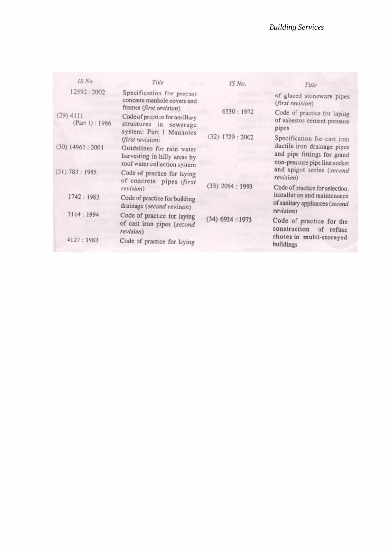
Building Services

Building Services
Annex A
Detailed Structural and explanatory notes
CPCprov code 86724
Structure Notes
Hierarchy
Section: 8 – Business services; agricultural, mining and manufacturing services
Division : 86 – Legal, accounting, auditing and book-keeping services; taxation services;
market research and public opinion polling services; management and consulting services;
architectural, engineering and other technical services
Group: 867 – Architectural, engineering and other technical services
Class: 8672 – Engineering services
Subclass: 86724 - Engineering design services for the construction of civil engineering
works
Explanatory note
Engineering design services for the construction of civil engineering works, such as
bridges and viaducts, dams, catchment basin, retaining walls, irrigation systems, flood
control works, tunnels, highways and streets including interchanges and related works,
locks, canals, wharves and harbours works, water supply and sanitation works such as
water distribution systems, water, sewage, industrial and solid waste treatment plants and
other civil engineering project.
Design services consists of one or a combination of the following: preliminary plans,
Specifications and cost estimates to define the engineering design concept; final plans,
Specifications and cost estimates, including working drawings,
Specifications regarding materials to be used, method of installation, time limitations and
other Specifications necessary for tender submission and construction and expert advice to
the client at the time of calling for and accepting tenders; service during the construction
phase. Included are engineering design services for buildings if they are an integral part of
the engineering design for a civil engineering work.
This code corresponds to the following:
ISIC Rev.3 code(s)7421