my solar hydrogen and ammonia - nh3 fuel … · my solar hydrogen and ammonia fueled tractor and...
TRANSCRIPT

1

MY SOLAR HYDROGEN AND AMMONIA FUELED TRACTOR AND FERTILIZER
SYSTEM
Jay Schmuecker
2

TOPICS
• Background
• System Description
• Hydrogen Storage
• Ammonia Generation
• System Controls
• System Schematic
• Tractor
• The Result
3

BACKGROUND
• Corn and soybeans are raised on our 320 acre farm.
• 3000 pounds of hydrogen is needed to replace the fossil fuels used.
– A pound of hydrogen contains the energy of a little less than two quarts of gasoline.
• 175 pounds of nitrogen/acre is applied to the corn cropland each year.
• A significant fraction Earth’s population is dependent on nitrogen fertilized foods.
• When ammonia is used, 4500 pounds of hydrogen is applied.
• Ammonia containing 5800 pounds
4

BACKGROUND
• As a memorial to my father, a hydrogen use advocate, on the Iowa farm where he was raised; we have the ability to make from only solar power, water, and air:
– Hydrogen, for use as a fuel and to make:
– Ammonia, for use as a fuel and fertilizer
• I’m also doing this to make the public, especially farmers, aware that as fossil energy costs increase, we will have to find other materials for use as farm fuels and fertilizers.
– We are demonstrating an alternative.
5

SYSTEM DESCRIPTION
• Three two axis trackers, rated at 8.1 kw total, provide power to inverters.
• Unused power is fed to the grid.
• Short term peak power is drawn from the grid.
6

SYSTEM DESCRIPTION
• An electrolyzer rated to provide .2 lbs (40scf) of hydrogen/hr.
• 7kw is required to start the unit, then the output is throttled to match the solar array output.
7

SYSTEM DESCRIPTION
• Two 5 hp air compressors are used together or separately to drive the pumps.
• Air is routed through drying coils, refrigerant and desiccant dryers.
8

HYDROGEN STORAGE
• The produced hydrogen is stored at 200 psi in the 1000 gal staging tank at the rear.
• Then it is pumped into the 8 composite storage tanks.
9

HYDROGEN STORAGE
• Compressed air drives the storage pump that compresses hydrogen to 3600 psi in the storage tanks.
• After storage tank hydrogen has been bleed into the tractor, the tractor pump pumps hydrogen into the four tractor tanks.
• Hydrogen is available to flow to the ammonia generation subsystem
10
AMMONIA GENERATION
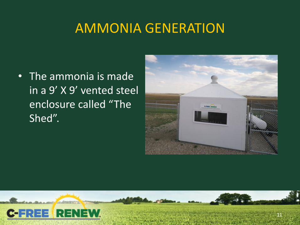
• The ammonia is made in a 9’ X 9’ vented steel enclosure called “The Shed”.
11
AMMONIA GENERATION
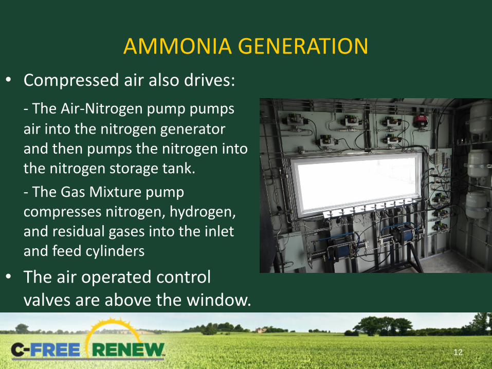
• Compressed air also drives:
- The Air-Nitrogen pump pumps air into the nitrogen generator and then pumps the nitrogen into the nitrogen storage tank.
- The Gas Mixture pump compresses nitrogen, hydrogen, and residual gases into the inlet and feed cylinders
• The air operated control valves are above the window.
12

AMMONIA GENERATION
• The nitrogen is separated from the air and pumped into the 1000 gallon nitrogen storage tank.
• Eye wash is provided, if needed.
13
AMMONIA GENERATION
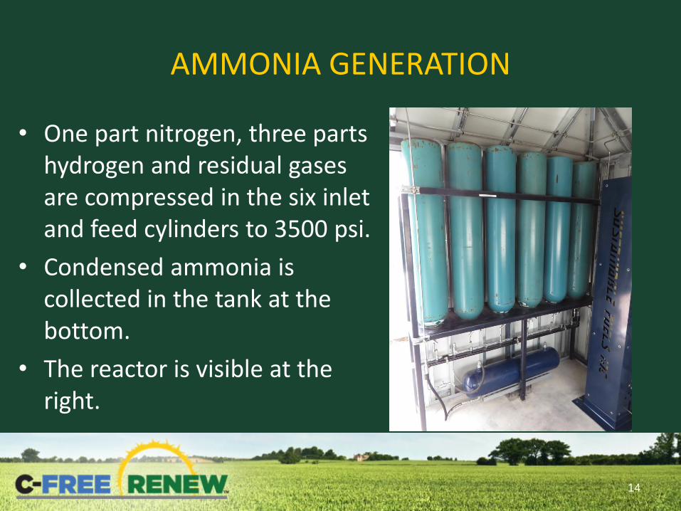
• One part nitrogen, three parts hydrogen and residual gases are compressed in the six inlet and feed cylinders to 3500 psi.
• Condensed ammonia is collected in the tank at the bottom.
• The reactor is visible at the right.
14

AMMONIA GENERATION
• The reactor before being insulated and enclosed.
• Internal temperatures run 450 – 550 degrees C.
15

AMMONIA GENERATION
16
• Electrical heaters around the reactor and on the top incoming gas line heat the gases to start the reaction.
• Once the reaction is started, the inlet gases are routed in the bottom of the reactor where the exit gases preheat it.
• As the inlet cylinders are emptied, the high reactor pressure is maintained by the gas mixture pump and feed cylinder.

AMMONIA GENERATION
• The mixture flows through the cooling coil and into the three left outlet cylinders where the ammonia condenses.
• The right cylinder, the feed cylinder, is pumped to 3500 psi to maintain reactor efficiency as the inlet cylinder pressure falls to 350 psi.
• All ammonia is collected in the collector tank at the bottom.
17

AMMONIA GENERATION • About 18 hours are needed to
load the inlet cylinders, and about 11 hours to react the gases to make 6 gallons of ammonia.
• The liquid ammonia is bled from the collector tanks to the mini-nurse tank.
– Ammonia is pumped into the tractor tank using special hoses.
– The full nurse tank will fertilize 3 acres of corn cropland.
18

AMMONIA GENERATION
• System controlled by automated valves.
• Ammonia containing components can be vented through top Shed vent if needed.
19
SYSTEM CONTROLS
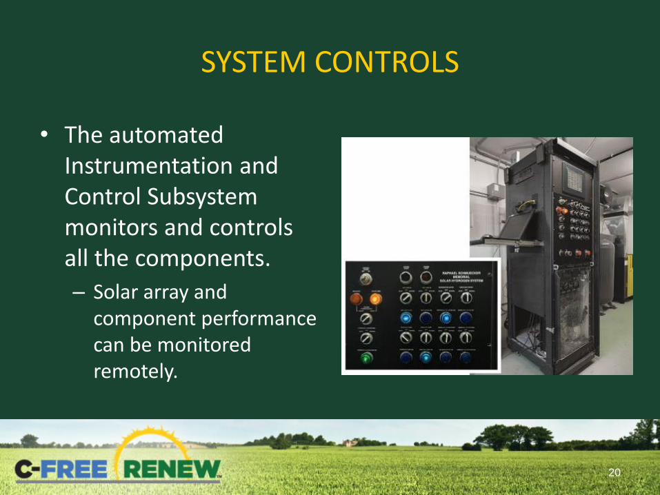
• The automated Instrumentation and Control Subsystem monitors and controls all the components.
– Solar array and component performance can be monitored remotely.
20

SYSTEM SCHEMATIC
21
• The generation and use of these on-site renewably made fuels and fertilizer are C-FREE RENEW (Carbon Emission Free Renewable) Technology

TRACTOR
• A Hydrogen Engine Center 572 cu. in. 13.5 to 1 compression ration V-8 engine is fueled by hydrogen or a mixture of hydrogen and ammonia.
• Engine Schematic
22

TRACTOR
• Hydrogen enters the engine through injectors in the intake manifold and it is ignited by spark plugs.
23

TRACTOR
• After the engine is started and before shutdown, a solenoid valve allows liquid ammonia into the vaporizer.
• The resulting gases flow through the mixer where they are blended with the engine intake air.
24

TRACTOR
• The energy contained in the 60 gallon ammonia tank is equivalent to that contained in two of the 21” X 10’ long 3000 psi hydrogen storage tanks.
25

THE RESULT:
26
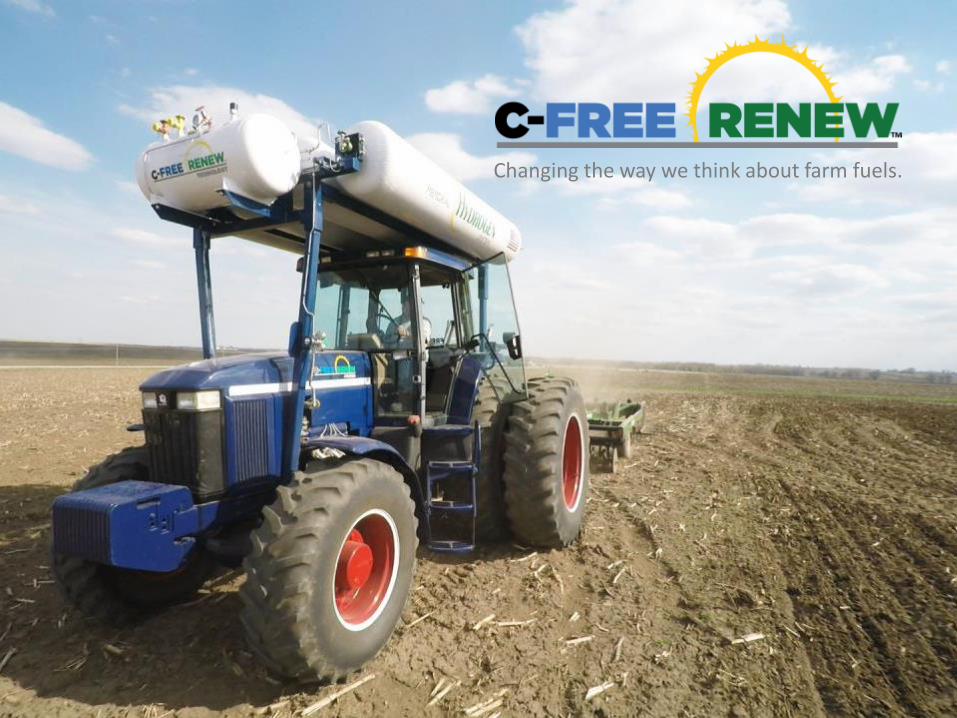
27
Changing the way we think about farm fuels.