my notes for edx 8.02x "electricity and magnetism"
DESCRIPTION
My notes, mostly from the lectures. Not 100% is covered, and they are absolutely not a substitute for the lectures themselves.Also contains (my own) homework and exam solutions.TRANSCRIPT
Notes for edX/MITx 8.02x “Electricity and Magnetism”,Spring 2013
Thomas Backman, [email protected]
June 18, 2013
Contents
0 Preface/disclaimer 6
1 Week 1 71.1 Coulomb’s law . . . . . . . . . . . . . . . . . . . . . . . . . . . . . . . . . . . . . . . . . . . 71.2 Electric fields . . . . . . . . . . . . . . . . . . . . . . . . . . . . . . . . . . . . . . . . . . . 7
1.2.1 Multiple charges . . . . . . . . . . . . . . . . . . . . . . . . . . . . . . . . . . . . . 81.2.2 Electric field lines . . . . . . . . . . . . . . . . . . . . . . . . . . . . . . . . . . . . . 91.2.3 Dipoles . . . . . . . . . . . . . . . . . . . . . . . . . . . . . . . . . . . . . . . . . . . 9
1.3 Electric flux and Gauss’s law . . . . . . . . . . . . . . . . . . . . . . . . . . . . . . . . . . . 91.3.1 Quick facts . . . . . . . . . . . . . . . . . . . . . . . . . . . . . . . . . . . . . . . . 91.3.2 Slower this time... . . . . . . . . . . . . . . . . . . . . . . . . . . . . . . . . . . . . . 101.3.3 Gauss’s law . . . . . . . . . . . . . . . . . . . . . . . . . . . . . . . . . . . . . . . . 11
2 Week 2 142.1 Electrostatic Potential Energy and Electric Potential . . . . . . . . . . . . . . . . . . . . . 14
2.1.1 Electrostatic Potential Energy . . . . . . . . . . . . . . . . . . . . . . . . . . . . . . 142.1.2 Electric potential . . . . . . . . . . . . . . . . . . . . . . . . . . . . . . . . . . . . . 152.1.3 More on electric potential . . . . . . . . . . . . . . . . . . . . . . . . . . . . . . . . 18
2.2 Electric fields inside hollow conductors . . . . . . . . . . . . . . . . . . . . . . . . . . . . . 192.3 High-voltage breakdown and lightning . . . . . . . . . . . . . . . . . . . . . . . . . . . . . 20
2.3.1 Electric breakdown . . . . . . . . . . . . . . . . . . . . . . . . . . . . . . . . . . . . 21
3 Week 3 233.1 Capacitance and Field Energy . . . . . . . . . . . . . . . . . . . . . . . . . . . . . . . . . . 23
3.1.1 Field Energy . . . . . . . . . . . . . . . . . . . . . . . . . . . . . . . . . . . . . . . 233.1.2 Capacitance . . . . . . . . . . . . . . . . . . . . . . . . . . . . . . . . . . . . . . . . 24
3.2 Dielectrics . . . . . . . . . . . . . . . . . . . . . . . . . . . . . . . . . . . . . . . . . . . . . 263.2.1 More on capacitors . . . . . . . . . . . . . . . . . . . . . . . . . . . . . . . . . . . . 303.2.2 A bit on van de Graaff generators . . . . . . . . . . . . . . . . . . . . . . . . . . . . 30
3.3 Current, resistivity and Ohm’s law . . . . . . . . . . . . . . . . . . . . . . . . . . . . . . . 31
4 Week 4 344.1 Batteries and EMF . . . . . . . . . . . . . . . . . . . . . . . . . . . . . . . . . . . . . . . . 34
4.1.1 Kirchhoff’s rules . . . . . . . . . . . . . . . . . . . . . . . . . . . . . . . . . . . . . . 354.1.2 Basic circuit analysis . . . . . . . . . . . . . . . . . . . . . . . . . . . . . . . . . . . 36
4.2 Magnetic Field and Torques . . . . . . . . . . . . . . . . . . . . . . . . . . . . . . . . . . . 364.2.1 The B Field . . . . . . . . . . . . . . . . . . . . . . . . . . . . . . . . . . . . . . . . 37
4.3 Review for Exam 1 . . . . . . . . . . . . . . . . . . . . . . . . . . . . . . . . . . . . . . . . 384.3.1 That’s it . . . . . . . . . . . . . . . . . . . . . . . . . . . . . . . . . . . . . . . . . . 39
1
5 Week 5 405.1 Moving Charges in Magnetic Fields . . . . . . . . . . . . . . . . . . . . . . . . . . . . . . . 40
5.1.1 Moving charges, radii and special relativity . . . . . . . . . . . . . . . . . . . . . . . 405.1.2 Isotope separation . . . . . . . . . . . . . . . . . . . . . . . . . . . . . . . . . . . . 425.1.3 Particle accelerators/cyclotrons . . . . . . . . . . . . . . . . . . . . . . . . . . . . . 435.1.4 Cloud chambers and bubble chambers . . . . . . . . . . . . . . . . . . . . . . . . . 45
5.2 Biot-Savart Law . . . . . . . . . . . . . . . . . . . . . . . . . . . . . . . . . . . . . . . . . . 465.3 Ampere’s law . . . . . . . . . . . . . . . . . . . . . . . . . . . . . . . . . . . . . . . . . . . 48
5.3.1 The magnetic field of a solenoid . . . . . . . . . . . . . . . . . . . . . . . . . . . . . 49
6 Week 6 516.1 Electromagnetic induction . . . . . . . . . . . . . . . . . . . . . . . . . . . . . . . . . . . . 51
6.1.1 Lenz’s law . . . . . . . . . . . . . . . . . . . . . . . . . . . . . . . . . . . . . . . . . 516.1.2 Magnetic flux . . . . . . . . . . . . . . . . . . . . . . . . . . . . . . . . . . . . . . . 526.1.3 Faraday’s law . . . . . . . . . . . . . . . . . . . . . . . . . . . . . . . . . . . . . . . 536.1.4 The breakdown of intuition . . . . . . . . . . . . . . . . . . . . . . . . . . . . . . . 54
6.2 Motional EMF and dynamos . . . . . . . . . . . . . . . . . . . . . . . . . . . . . . . . . . . 566.2.1 Changing the area . . . . . . . . . . . . . . . . . . . . . . . . . . . . . . . . . . . . 576.2.2 Eddy currents . . . . . . . . . . . . . . . . . . . . . . . . . . . . . . . . . . . . . . . 59
6.3 Displacement currents and synchronous motors . . . . . . . . . . . . . . . . . . . . . . . . 616.3.1 The amended Ampere’s law . . . . . . . . . . . . . . . . . . . . . . . . . . . . . . . 626.3.2 Displacement current . . . . . . . . . . . . . . . . . . . . . . . . . . . . . . . . . . . 646.3.3 Synchronous motors . . . . . . . . . . . . . . . . . . . . . . . . . . . . . . . . . . . 65
7 Week 7 687.1 How do magicians levitate women? . . . . . . . . . . . . . . . . . . . . . . . . . . . . . . . 68
7.1.1 The human heart . . . . . . . . . . . . . . . . . . . . . . . . . . . . . . . . . . . . . 687.1.2 Aurora borealis . . . . . . . . . . . . . . . . . . . . . . . . . . . . . . . . . . . . . . 707.1.3 Superconductivity and magnetic levitation . . . . . . . . . . . . . . . . . . . . . . . 71
7.2 Inductance and RL circuits . . . . . . . . . . . . . . . . . . . . . . . . . . . . . . . . . . . . 737.2.1 Direct-current RL circuits . . . . . . . . . . . . . . . . . . . . . . . . . . . . . . . . 757.2.2 Alternating-current RL circuits . . . . . . . . . . . . . . . . . . . . . . . . . . . . . 807.2.3 More on magnetic levitation . . . . . . . . . . . . . . . . . . . . . . . . . . . . . . . 82
7.3 Magnetic materials . . . . . . . . . . . . . . . . . . . . . . . . . . . . . . . . . . . . . . . . 837.3.1 A short note on motors . . . . . . . . . . . . . . . . . . . . . . . . . . . . . . . . . . 837.3.2 Magnetic dipole moment . . . . . . . . . . . . . . . . . . . . . . . . . . . . . . . . . 837.3.3 The source of magnetism in matter . . . . . . . . . . . . . . . . . . . . . . . . . . . 847.3.4 Magnetization . . . . . . . . . . . . . . . . . . . . . . . . . . . . . . . . . . . . . . . 857.3.5 Paramagnetism . . . . . . . . . . . . . . . . . . . . . . . . . . . . . . . . . . . . . . 867.3.6 Diamagnetism . . . . . . . . . . . . . . . . . . . . . . . . . . . . . . . . . . . . . . . 877.3.7 Ferromagnetism . . . . . . . . . . . . . . . . . . . . . . . . . . . . . . . . . . . . . . 88
8 Week 8 908.1 Hysteresis and electromagnets . . . . . . . . . . . . . . . . . . . . . . . . . . . . . . . . . . 90
8.1.1 Ferromagnetism and hysteresis . . . . . . . . . . . . . . . . . . . . . . . . . . . . . . 928.1.2 Maxwell’s equations . . . . . . . . . . . . . . . . . . . . . . . . . . . . . . . . . . . 95
8.2 Review for Exam 2 . . . . . . . . . . . . . . . . . . . . . . . . . . . . . . . . . . . . . . . . 96
9 Week 9 979.1 Transformers, Car Coils and RC circuits . . . . . . . . . . . . . . . . . . . . . . . . . . . . 97
9.1.1 RC circuits . . . . . . . . . . . . . . . . . . . . . . . . . . . . . . . . . . . . . . . . 979.1.2 Transformers . . . . . . . . . . . . . . . . . . . . . . . . . . . . . . . . . . . . . . . 1009.1.3 Spark plugs / “car coils” . . . . . . . . . . . . . . . . . . . . . . . . . . . . . . . . . 101
2
9.2 Driven RLC circuits and resonance . . . . . . . . . . . . . . . . . . . . . . . . . . . . . . . 1029.3 Traveling waves and standing waves . . . . . . . . . . . . . . . . . . . . . . . . . . . . . . . 105
9.3.1 Traveling waves . . . . . . . . . . . . . . . . . . . . . . . . . . . . . . . . . . . . . . 1059.3.2 Standing waves . . . . . . . . . . . . . . . . . . . . . . . . . . . . . . . . . . . . . . 1069.3.3 Musical instruments . . . . . . . . . . . . . . . . . . . . . . . . . . . . . . . . . . . 107
10 Week 10 10910.1 Resonance, electromagnetic waves . . . . . . . . . . . . . . . . . . . . . . . . . . . . . . . . 109
10.1.1 Radar and measuring distance . . . . . . . . . . . . . . . . . . . . . . . . . . . . . . 11210.1.2 Radio . . . . . . . . . . . . . . . . . . . . . . . . . . . . . . . . . . . . . . . . . . . 113
10.2 Index of refraction and Poynting vector . . . . . . . . . . . . . . . . . . . . . . . . . . . . . 11310.2.1 Poynting vector . . . . . . . . . . . . . . . . . . . . . . . . . . . . . . . . . . . . . . 11310.2.2 Waves due to accelerating charges . . . . . . . . . . . . . . . . . . . . . . . . . . . . 11410.2.3 Spherical waves and the Poynting vector . . . . . . . . . . . . . . . . . . . . . . . . 11510.2.4 Photons and radiation pressure . . . . . . . . . . . . . . . . . . . . . . . . . . . . . 11610.2.5 Polarization . . . . . . . . . . . . . . . . . . . . . . . . . . . . . . . . . . . . . . . . 118
10.3 Snell’s law, refraction and total reflection . . . . . . . . . . . . . . . . . . . . . . . . . . . . 12010.3.1 Total internal reflection . . . . . . . . . . . . . . . . . . . . . . . . . . . . . . . . . . 12110.3.2 Frequency and wavelength in refraction . . . . . . . . . . . . . . . . . . . . . . . . . 12210.3.3 Dispersion, prisms and white light . . . . . . . . . . . . . . . . . . . . . . . . . . . . 12310.3.4 Primary colors . . . . . . . . . . . . . . . . . . . . . . . . . . . . . . . . . . . . . . 124
11 Week 11 12611.1 Polarizers and and Malus’s law . . . . . . . . . . . . . . . . . . . . . . . . . . . . . . . . . 126
11.1.1 Polarization by reflection . . . . . . . . . . . . . . . . . . . . . . . . . . . . . . . . . 12711.1.2 Polarization by scattering . . . . . . . . . . . . . . . . . . . . . . . . . . . . . . . . 12911.1.3 Scattering demonstration and Rayleigh scattering . . . . . . . . . . . . . . . . . . . 131
11.2 Rainbows . . . . . . . . . . . . . . . . . . . . . . . . . . . . . . . . . . . . . . . . . . . . . 13211.2.1 Other atmospherical optical phenomena . . . . . . . . . . . . . . . . . . . . . . . . 13811.2.2 Polarization of rainbows . . . . . . . . . . . . . . . . . . . . . . . . . . . . . . . . . 138
11.3 Review for Exam 3 . . . . . . . . . . . . . . . . . . . . . . . . . . . . . . . . . . . . . . . . 139
12 Week 12 14012.1 Double slit interference and interferometers . . . . . . . . . . . . . . . . . . . . . . . . . . . 14012.2 Gratings and resolving power . . . . . . . . . . . . . . . . . . . . . . . . . . . . . . . . . . 14512.3 Single-slit diffraction . . . . . . . . . . . . . . . . . . . . . . . . . . . . . . . . . . . . . . . 14712.4 Doppler effect and the Big Bang . . . . . . . . . . . . . . . . . . . . . . . . . . . . . . . . . 149
12.4.1 The Doppler effect and light . . . . . . . . . . . . . . . . . . . . . . . . . . . . . . . 15012.4.2 Big Bang cosmology . . . . . . . . . . . . . . . . . . . . . . . . . . . . . . . . . . . 151
12.5 Farewell special . . . . . . . . . . . . . . . . . . . . . . . . . . . . . . . . . . . . . . . . . . 152
13 Homework problems 15313.1 Week 2 . . . . . . . . . . . . . . . . . . . . . . . . . . . . . . . . . . . . . . . . . . . . . . . 153
13.1.1 Problem 1: Motion of charged particle in electric field . . . . . . . . . . . . . . . . . 15313.1.2 Problem 2: Three plates capacitor . . . . . . . . . . . . . . . . . . . . . . . . . . . . 15413.1.3 Problem 3: Electric field, potential, and electrostatic potential energy . . . . . . . . 15413.1.4 Problem 4: Electric field of a charged ring . . . . . . . . . . . . . . . . . . . . . . . 15513.1.5 Problem 5: Two spherical conductors . . . . . . . . . . . . . . . . . . . . . . . . . . 15813.1.6 Problem 6: Two conducting hollow cylinders . . . . . . . . . . . . . . . . . . . . . . 15913.1.7 Problem 7: Speed of an electron . . . . . . . . . . . . . . . . . . . . . . . . . . . . . 161
13.2 Week 3 . . . . . . . . . . . . . . . . . . . . . . . . . . . . . . . . . . . . . . . . . . . . . . . 16213.2.1 Problem 1: Spherical capacitor . . . . . . . . . . . . . . . . . . . . . . . . . . . . . 16213.2.2 Problem 2: Coaxial cylinders . . . . . . . . . . . . . . . . . . . . . . . . . . . . . . 163
3
13.2.3 Problem 3: The effect of a dielectric medium on capacitance . . . . . . . . . . . . . 16513.2.4 Problem 4: Coaxial cable with dielectric . . . . . . . . . . . . . . . . . . . . . . . . 16613.2.5 Problem 5: Capacitor network . . . . . . . . . . . . . . . . . . . . . . . . . . . . . . 16813.2.6 Problem 6: Resistances of conducting wires . . . . . . . . . . . . . . . . . . . . . . 16913.2.7 Problem 7: Resistor network . . . . . . . . . . . . . . . . . . . . . . . . . . . . . . . 170
13.3 Week 4 . . . . . . . . . . . . . . . . . . . . . . . . . . . . . . . . . . . . . . . . . . . . . . . 17113.4 Week 5 . . . . . . . . . . . . . . . . . . . . . . . . . . . . . . . . . . . . . . . . . . . . . . . 171
13.4.1 Problem 1: Lorentz Force . . . . . . . . . . . . . . . . . . . . . . . . . . . . . . . . 17113.4.2 Problem 2: Motion of a charged particle in magnetic field . . . . . . . . . . . . . . . 17213.4.3 Problem 3: Cyclotron . . . . . . . . . . . . . . . . . . . . . . . . . . . . . . . . . . . 17313.4.4 Problem 4: Rectangular current loop . . . . . . . . . . . . . . . . . . . . . . . . . . 17313.4.5 Problem 5: Resistor network . . . . . . . . . . . . . . . . . . . . . . . . . . . . . . . 17513.4.6 Problem 6: Coaxial current loops . . . . . . . . . . . . . . . . . . . . . . . . . . . . 17613.4.7 Problem 7: Parallel plate capacitor . . . . . . . . . . . . . . . . . . . . . . . . . . . 176
13.5 Week 6 . . . . . . . . . . . . . . . . . . . . . . . . . . . . . . . . . . . . . . . . . . . . . . . 17913.5.1 Problem 1: Ampere’s law in action . . . . . . . . . . . . . . . . . . . . . . . . . . . 17913.5.2 Problem 2: Intuition breaks down . . . . . . . . . . . . . . . . . . . . . . . . . . . . 18113.5.3 Problem 3: Helmholtz coils . . . . . . . . . . . . . . . . . . . . . . . . . . . . . . . 18213.5.4 Problem 4: Spinning loop in a magnetic field . . . . . . . . . . . . . . . . . . . . . . 18413.5.5 Problem 5: Loop in a magnetic field . . . . . . . . . . . . . . . . . . . . . . . . . . 18513.5.6 Problem 6: Electrodynamic tether . . . . . . . . . . . . . . . . . . . . . . . . . . . . 18613.5.7 Problem 7: Motor . . . . . . . . . . . . . . . . . . . . . . . . . . . . . . . . . . . . . 18613.5.8 Problem 8: Auroral zone . . . . . . . . . . . . . . . . . . . . . . . . . . . . . . . . . 188
13.6 Week 7 . . . . . . . . . . . . . . . . . . . . . . . . . . . . . . . . . . . . . . . . . . . . . . . 18813.6.1 Problem 1: Magnetic energy of a solenoid . . . . . . . . . . . . . . . . . . . . . . . 18813.6.2 Problem 2: Displacement current . . . . . . . . . . . . . . . . . . . . . . . . . . . . 19013.6.3 Problem 3: RL circuit . . . . . . . . . . . . . . . . . . . . . . . . . . . . . . . . . . 19013.6.4 Problem 4: RL circuit . . . . . . . . . . . . . . . . . . . . . . . . . . . . . . . . . . 19213.6.5 Problem 5: Opening a switch on an RL circuit . . . . . . . . . . . . . . . . . . . . . 19313.6.6 Problem 6: Self-inductance of a toroid . . . . . . . . . . . . . . . . . . . . . . . . . 19613.6.7 Problem 7: RL circuit . . . . . . . . . . . . . . . . . . . . . . . . . . . . . . . . . . 197
13.7 Week 8 . . . . . . . . . . . . . . . . . . . . . . . . . . . . . . . . . . . . . . . . . . . . . . . 19813.8 Week 9 . . . . . . . . . . . . . . . . . . . . . . . . . . . . . . . . . . . . . . . . . . . . . . . 199
13.8.1 Problem 1: RC circuit . . . . . . . . . . . . . . . . . . . . . . . . . . . . . . . . . . 19913.8.2 Problem 2: RC circuit . . . . . . . . . . . . . . . . . . . . . . . . . . . . . . . . . . 20013.8.3 Problem 3: RLC circuit . . . . . . . . . . . . . . . . . . . . . . . . . . . . . . . . . 20113.8.4 Problem 4: An LRC circuit . . . . . . . . . . . . . . . . . . . . . . . . . . . . . . . 20113.8.5 Problem 5: Design a flute . . . . . . . . . . . . . . . . . . . . . . . . . . . . . . . . 20313.8.6 Problem 6: Width of resonance peak . . . . . . . . . . . . . . . . . . . . . . . . . . 20313.8.7 Problem 7: Standing wave . . . . . . . . . . . . . . . . . . . . . . . . . . . . . . . . 20413.8.8 Problem 8: Traveling wave . . . . . . . . . . . . . . . . . . . . . . . . . . . . . . . . 20513.8.9 Problem 9: Lightly damped undriven circuit . . . . . . . . . . . . . . . . . . . . . . 206
13.9 Week 10 . . . . . . . . . . . . . . . . . . . . . . . . . . . . . . . . . . . . . . . . . . . . . . 20813.9.1 Problem 1: Traveling electromagnetic waves . . . . . . . . . . . . . . . . . . . . . . 20813.9.2 Problem 2: A standing electromagnetic wave . . . . . . . . . . . . . . . . . . . . . . 20913.9.3 Problem 3: E-M waves - Maxwell’s equations, and the speed of light . . . . . . . . . 21113.9.4 Problem 4: Polarized radiation . . . . . . . . . . . . . . . . . . . . . . . . . . . . . 21313.9.5 Problem 5: Polarization of electromagnetic radiation . . . . . . . . . . . . . . . . . 21613.9.6 Problem 6: Poynting vector . . . . . . . . . . . . . . . . . . . . . . . . . . . . . . . 21713.9.7 Problem 7: Intensity of the sun . . . . . . . . . . . . . . . . . . . . . . . . . . . . . 21813.9.8 Problem 8: Snell’s law in action: fiber optics! . . . . . . . . . . . . . . . . . . . . . 219
13.10Week 11 . . . . . . . . . . . . . . . . . . . . . . . . . . . . . . . . . . . . . . . . . . . . . . 221
4
13.11Week 12 . . . . . . . . . . . . . . . . . . . . . . . . . . . . . . . . . . . . . . . . . . . . . . 22113.11.1Problem 1: Primary rainbow . . . . . . . . . . . . . . . . . . . . . . . . . . . . . . . 22113.11.2Problem 2: Polarization of primary rainbow . . . . . . . . . . . . . . . . . . . . . . 22313.11.3Problem 3: Glassbow . . . . . . . . . . . . . . . . . . . . . . . . . . . . . . . . . . . 22313.11.4Problem 4: Secondary rainbow . . . . . . . . . . . . . . . . . . . . . . . . . . . . . 22413.11.5Problem 5: Diffraction pattern . . . . . . . . . . . . . . . . . . . . . . . . . . . . . . 22513.11.6Problem 6: Optical resolution of the human eye . . . . . . . . . . . . . . . . . . . . 226
14 Exam problems 22714.1 Midterm 1 . . . . . . . . . . . . . . . . . . . . . . . . . . . . . . . . . . . . . . . . . . . . . 227
14.1.1 Problem 1: Electric field on the surface of a conductor . . . . . . . . . . . . . . . . 22714.1.2 Problem 2: Non-conducting charged planes . . . . . . . . . . . . . . . . . . . . . . . 22814.1.3 Problem 3: Incandescent bulbs . . . . . . . . . . . . . . . . . . . . . . . . . . . . . 22914.1.4 Problem 4: Circuit . . . . . . . . . . . . . . . . . . . . . . . . . . . . . . . . . . . . 23014.1.5 Problem 5: Point charge in a hollow conducting sphere . . . . . . . . . . . . . . . . 23114.1.6 Problem 6: Charges on an equilateral triangle . . . . . . . . . . . . . . . . . . . . . 23214.1.7 Problem 7: Capacitor network . . . . . . . . . . . . . . . . . . . . . . . . . . . . . . 233
14.2 Midterm 2 . . . . . . . . . . . . . . . . . . . . . . . . . . . . . . . . . . . . . . . . . . . . . 23514.2.1 Problem 1: RL circuit . . . . . . . . . . . . . . . . . . . . . . . . . . . . . . . . . . 23514.2.2 Problem 2: Non-conservative fields . . . . . . . . . . . . . . . . . . . . . . . . . . . 23614.2.3 Problem 3: Bainbridge mass spectrometer . . . . . . . . . . . . . . . . . . . . . . . 23614.2.4 Problem 4: RL circuit . . . . . . . . . . . . . . . . . . . . . . . . . . . . . . . . . . 23814.2.5 Problem 5: Magnetic field of a loop . . . . . . . . . . . . . . . . . . . . . . . . . . . 23814.2.6 Problem 6: Magnetic field of a current-carrying ribbon . . . . . . . . . . . . . . . . 23914.2.7 Problem 7: Magnetic field of a rotating charged sphere . . . . . . . . . . . . . . . . 240
14.3 Midterm 3 . . . . . . . . . . . . . . . . . . . . . . . . . . . . . . . . . . . . . . . . . . . . . 24314.3.1 Problem 1: RC Circuit . . . . . . . . . . . . . . . . . . . . . . . . . . . . . . . . . . 24314.3.2 Problem 2: RLC circuit . . . . . . . . . . . . . . . . . . . . . . . . . . . . . . . . . 24414.3.3 Problem 3: Energy flow of a capacitor . . . . . . . . . . . . . . . . . . . . . . . . . 24714.3.4 Problem 4: Electromagnet with small air gap . . . . . . . . . . . . . . . . . . . . . 25014.3.5 Problem 5: RLC Circuit . . . . . . . . . . . . . . . . . . . . . . . . . . . . . . . . . 25114.3.6 Problem 6: Electromagnetic wave . . . . . . . . . . . . . . . . . . . . . . . . . . . . 25214.3.7 Problem 7: Radiation pressure on the Earth . . . . . . . . . . . . . . . . . . . . . . 253
14.4 Final Exam . . . . . . . . . . . . . . . . . . . . . . . . . . . . . . . . . . . . . . . . . . . . 25514.4.1 Problem 1: Loop in a Magnetic Field . . . . . . . . . . . . . . . . . . . . . . . . . . 25514.4.2 Problem 2: Non-conducting infinite sheet and infinite parallel slab . . . . . . . . . . 25614.4.3 Problem 3: RLC circuit . . . . . . . . . . . . . . . . . . . . . . . . . . . . . . . . . 26014.4.4 Problem 4: Plane electromagnetic wave . . . . . . . . . . . . . . . . . . . . . . . . . 26214.4.5 Problem 5: Loop in a magnetic field . . . . . . . . . . . . . . . . . . . . . . . . . . 26314.4.6 Problem 6: Charged particles in a magnetic field . . . . . . . . . . . . . . . . . . . . 26514.4.7 Problem 7: Diffraction pattern . . . . . . . . . . . . . . . . . . . . . . . . . . . . . . 26614.4.8 Problem 8: Capacitor washers . . . . . . . . . . . . . . . . . . . . . . . . . . . . . . 26814.4.9 Problem 9: Circuit . . . . . . . . . . . . . . . . . . . . . . . . . . . . . . . . . . . . 27214.4.10Problem 10: An LC circuit . . . . . . . . . . . . . . . . . . . . . . . . . . . . . . . . 27514.4.11Problem 11: Dielectric sphere . . . . . . . . . . . . . . . . . . . . . . . . . . . . . . 27814.4.12Problem 12: Parallel RLC . . . . . . . . . . . . . . . . . . . . . . . . . . . . . . . . 279
5
Chapter 0
Preface/disclaimer
The most important thing to keep in mind where reading these notes is that I’m just another student,taking this course. I have almost zero previous knowledge of electromagnetism, though I previously tookthe MITx 6.002x “Circuits and Electronics” class. That knowledge helped only in small parts of this course,however, and I’ve learned almost everything except circuit analysis on a week-to-week basis, while writingdown all this.
In other words: there may well be errors in here!In part because I make typos and other stupid mistakes, but also because I might have misunderstoodsome concept somewhere. I usually point out whenever I feel less than certain, but that doesn’t guaranteeanything, of course.
These notes are made up of three parts: lecture notes, homework solutions, and exam solutions.The lecture notes are in part from the lectures as-is (essentially a transcription), but I do add my owncomments and extra information here and there.They will lack some information from the lectures, as I don’t write down everything (for example, I rarelywrite down anything during demonstrations, only their results if necessary), but also have some tiny extrabits (from the book, things I knew to begin with, or things I look up elsewhere).
I write the homework solutions as I solve them, so the text and even the answers are usually written beforeI’ve even clicked “check”. Still, I look at the staff’s solutions after the fact and at least if I remember usinga different method, I try to check that I wasn’t just lucky in getting the correct answer for myself.The exact same thing applies to the exam solutions as well.
There are no notes/solutions for homework 1, as I started writing the solutions down the second week.
By the way: I certainly welcome all feedback, corrections, comments and whatnot! Too small a fractionof my daily e-mail is written by actual human beings (rather than being spam, mass-emails/mailing lists,forum notices, ...), anyway. :-)
6
Chapter 1
Week 1
1.1 Coulomb’s lawTwo point charges q1 and q2, separated by distance r, equal in magnitude and of equal polarity, will repelone another. The force on q2 due to q1, in the direction 180 degrees opposite to to the direction of q1, is
~F1,2 =q1q2K
r2· ˆr1,2
... where K is Coulomb’s constant, roughly 8.987551787 · 109 N · m2 · C−2, and ~F1,2 means the force oncharge 2 due to charge 1. ˆr1,2 is the unit vector in the direction from charge 1 to charge 2. And, sinceeach force has an equal and opposite reaction, we also have a ~F2,1 ( ~F2,1 = − ~F1,2)
Note how the equation is sign-sensitive: if both changes have the same sign, the force forces the particlesapart. On the other hand, if they differ in sign, the result will be negative, and so the force vector willpoint towards q1 from q2 (and vice versa) instead of away from it.
Also:
K =1
4πε0
where ε0 is the permittivity of free space, also (more recently) known as the electric constant.
ε0 ≈ 8.854187 · 10−12 farad/meter
1.2 Electric fieldsImagine a setup very similar to the one above.We have a charge, Q+, and a test charge q a distance r away. As before, the force on the test charge is
~F =QqK
r2r
If we take that force vector, and “divide out” q, the test charge, we get the electric field at the point inspace where q is located. Let’s call that point p; in that case, we have the electric field ~Ep:
~Ep =~F
q=QK
r2r
where r is again the unit vector pointing away from Q in the direction of the test charge.By convention, we choose the electric field to be such that the field vector is in the direction of the forceon a positive test charge. If the test charge were negative, the electric force would attract the two charges
7
toward each other, and the electric field would be pointing towards Q.
Put more simply: for a positive charge, we draw the field as a set of arrows pointing from the charge andaway. This field is spherically symmetric, and as we saw above, decays in a inverse-r-squared fashion. Ifthe charge is instead negative, we draw it as a set of arrows pointing towards the charge, again with moreforce (longer arrows, to represent larger vector magnitudes) closer to the charge.
The electric field can be thought of as the force per unit charge (as we have divided out the charge of theequation).
1.2.1 Multiple charges
To calculate the net electric field for multiple charges, we use the superposition principle: very simply, wecalculate the electric field due to each charge alone, at a certain point p; the net electric field a that pointis then simply the vector sum of all these individual electric fields.
For example, for a set of three charges, Q1+, Q2− and Q3−, we get three separate electric fields: one thatrepels from Q1, and two that attract towards Q2 and Q3 respectively. The net electric field is then
~Ep = ~E1 + ~E2 + ~E3
and more generally, for a set of i charges, the same sum holds:
~Ep =∑i
~Ei
So depending on how much change each of these points hold, the resulting vector may be in any direction,with any magnitude; we simply cannot say until we do a quantitative calculation of the force.
Now, then, what is the point of calculating this electric field? Well, now we know what the electric fieldat that point is, we can very easily calculate the force vector for any charge we place at the location, likethis:
~F = q ~E
So, in other words, we simply multiply the charge by the electric field vector, and we get the force. q canbe large or small, positive or negative, and the result will still come out right.If the charge is large, the force will be large, and vice versa.If the charge is positive, the force vector will be in the same direction as ~E. If the charge is negative, itwill be in the opposite direction of ~E.
In a system of multiple charges, there may be a point in space where the electric field’s magnitude isexactly zero, because the forces from all the charges in the system perfectly cancel out.One of the simplest such cases is when you have a set of three charges, equal in polarity and magnitude,arranged at the vertices of an equilateral triangle. In such a case, the electric field strength will be exactlyzero in the middle of the three charges.
Charges of differing polarity can also produce points with no net force.Imagine a one-dimensional line, measuared in meters. At the exact middle, 0 m, we have a 1µC charge.At 4 m, we have a −0.5µC charge.For a positive test charge located in between these two, i.e. on the interval (0, 4), the forces will beadditive; the positive charge at 0 will push towards the right, and the negative charge at 4 m will pulltowards the right.If we go past 4 m, however, there will come a point where the force cancels out exactly: the stronger, but
8
more distant positive charge repels, and the weaker, but closer negative charge attracts.In this example, that spot is at 8 + 4
√2 meters, which can be found by solving the equation relating the
two electric fields:
~E0 =1µK
r2x
~E4 =−0.5µK
(r − 4)2x
~E0 + ~E4 = 0
where ~E0 is the electric field due to the particle a 0 m alone, and ~E4 the field due to the negative particleat 4 m alone.If we solve the equation (on the third line above), we get ≈ 13.65 meters.
1.2.2 Electric field lines
There’s a second common way of visually representing electric fields, besides the vector field: electric fieldlines. Here, we lose some information about the field strength at any particular point, but can instead seethe curvature much more clearly.Such a representation would have a ton of lines coming from (or going to, for negative charges) each charge,curving around depending on other, nearby charges.The further away you get from a charge, the further apart the lines will become. This represents theinverse-r-squared weakening of the field.
One crucial aspect about these lines is that if you place a positive charge anywhere on a field line, theforce vector on that charge will always be tangential to the field line at that point. If the placed charge isnegative, the force vector will simply be the same but flipped 180 degrees around.
It is also important to note that because of this, the trajectory of a charge (say, released a 0 velocity) willnot follow any one field line exactly; the trajectory can be quite complex. Any time you reach a field line,however, the force vector will again be tangential to that field line.
1.2.3 Dipoles
As we saw above, with two charges of equal polarity, there is a point between the two where the forcecancels out, and the electric field is zero.If we instead have two charges, equal in magnitude but opposite in sign, we have a dipole. In this case,there is no point where the electric field is zero.
Two charges of unequal charge and opposite polarity will, as observed from “far” away, behave as a singlecharge whose value is the difference of the two. For example, a +3 change next to a -1 will “look” like a+2 charge from far away, and the electric field falls off with a inverse-r-squared relationship.With dipoles, that is no longer the case: the field falls off with an inverse-r-cubed relationship, i.e. itweakens much faster as the distance increases. This does make intuitive sense: from afar, it should actlike a single point charge with zero charge!
1.3 Electric flux and Gauss’s law
1.3.1 Quick facts
According to Wikipedia, electric flux is “the rate of flow per unit charge of the electric field”. It can bethought of as the number of electric field lines going through a surface.For a uniform electric field, the flux passing through a surface of vector area S is
9
ΦE = ~E · ~A = EA cos θ
where θ is the angle between the normal of the surface (the vector perpendicular to the surface) and theelectric field lines.For a non-uniform electric field, the flux can be calculated by using a surface integral:
ΦE =x
S
~E · ~dA
where ~dA is a vector area infinitesimal.
1.3.2 Slower this time...
OK, let’s start over. Say we have an open surface, e.g. a paper (unlike a closed surface, e.g. a bag or aballoon) placed in an electric field. We can divide the field into infinitesimals with area dA. Each of thesewill have a normal unit vector n that is perpendicular to it.Each of these infinitesimal areas will have a flux dφ associated with it, which can be calculated:
dΦE = ~E · ndA = ~E · ~dA = E dA cos θ
Here, θ is, as above, the angle between the normal and the electric field lines. The notation with andwithout the n are two ways of writing the same thing. One considers dA as an area, with a normal unitvector to give it direction, while the second combines the to into the vector area ~dA.The flux can be larger than, smaller than, or equal to zero.
One can make a useful parallel between electric flux and air flow. Consider a hollow rectangle positionperpendicular to a uniform air flow. In other words, the normal to the rectangle is parallel with the airflow. How much air goes through it? Well, it’s simply the rate of air flow multiplied by the rectangle’sarea.If we rotate the rectangle 90 degrees, such that the normal is now perpendicular to to the air flow, no airgoes through the rectangle - it is parallel to the air flow.If the angle is anything in between the two, we simply multiply the v ·A we already have by the cosine ofthe angle. That is, the air flow through the rectangle is given by vA cos θ.
The exact same way can be used to calculate the electric flux “through” the rectangle - multiply the electricfield vector and the vector area using the dot product, such that you get EA cos θ.
Example with a point charge
Say we have a point charge +Q, and a spherical surface with radius R surrounding it.For any chosen infinitesimal area dA on the surface, the normal will be radially outwards - as will theelectric field, since we have a positive point charge. In fact, the two will be parallel at all locations on thesurface, so the cosine of the angle between them is always 1.Not only that, but since we chose to do this with a spherical surface, the electric field has exactly thesame magnitude at all points along the surface. These facts, when combined, makes for an extremely easycalculation of the total flux - it is simply the magnitude of the electric field, times the surface area - EA,or in the case of a sphere, 4πR2E.
Well, E isQK
R2r, as we have seen previously, with r being the unit vector in the direction from the charge
to the chosen surface area infinitesimal. K, the Coulomb constant, has an exact definition (but we oftensimply use 9 · 109 instead, which about 0.14% off from the real value):
K =1
4πε0
10
If we substitute that in, we have~E =
Q
4πε0R2r
... which looks more complex, until we finalize the flux calculation by multiplying the electric field’smagnitude with the surface area of 4πR2:
E · 4πR2 =Q
ε0
Spectacular! Note not only how simple it is, but indeed that the radius term disappeared. And, since ε0 isa physical constant, we clearly see that the net charge is the only thing that determines the flux throughthis closed surface.Indeed, this also means that the result holds regardless of the shape of the surface used to confine thecharge. Whether it is a sphere, a cylinder, a box or just something entirely different, the amount of fluxis exactly the same.This can be intuitively understood if we go back to the air flow analogy: regardless of the bag’s size,assuming air could travel through it, it would have to get out of there somewhere regardless of the bag’ssize.
Now, since electric fields from multiple point charges are added using vector addition, it is clear that anycollection of charges inside this “bag” must behave in the same way. That leads us to:
1.3.3 Gauss’s law
Gauss’s law states that the electric flux through a closed surface, with nonzero net charge inside, is,regardless of the shape and size of the surface:
φ =
~E · ~dA =
∑Qins
ε0
where φ (also ΦE) is the total electric flux through the surface,∑Qins is the total electric charge inside
the surface, and ε0 as always the permittivity of free space.The ring in the integral symbol is to indicate that the surface we are integrating over is a closed surface.
Gauss’s law always holds, no matter how the charge is arranged inside the bag, or how it is shaped.It is, however, not very useful unless we have some form of symmetry. The main use of Gauss’s law isto calculate electric fields, and to do so, we need to take advantage of one of three forms of symmetry:spherical, to encapsulate a point charge or such; cylindrical, to encapsulate an infinite “wire” of charge;and planar, to calculate electric fields around an infinite plane. In all three cases, the charge distributionmust be uniform.
Gauss’s law application: a charged, hollow sphere
Let’s attempt an application of Gauss’s law, on a hollow, conductive sphere, with charge Q uniformlydistributed on the surface. The sphere is of radius R.First, we need to choose one of the gaussian surfaces: the spherical one, the cylinder (for the infinite wire)or the “pillbox”, also a cylinder, used for planar surfaces.Clearly, we want the spherical one in this case; we choose a concentric sphere (i.e. it is perfectly centeredon the charged sphere) such that the radius r of the “Gauss sphere” touches the point where we want tocalculate the electric field.Then, we note a few things: the problem is spherically symmetric, so the electric field’s magnitude at anypoint along the surface of our Gauss sphere must be exactly the same as for any other point on it. Thatfollows from the symmetry of the problem.Also, we know that the electric field is radially outwards (or inwards, if the charge is negative) - either
11
way, it is either parallel or antiparallel between any chosen dA on the surface.
Now that we have the same situation as before - the direction of E is always parallel with the surfacenormals, and we know how the surface area of a sphere - we can calculate the (again simply EA), andthen solve for the electric field.Let’s begin with the case of r < R, i.e. inside the hollow sphere:
E4πr2 =
∑Qins
ε0
E =
∑Qins
4πr2ε0
However, we know from the problem definition that there is no charge inside, so the numerator is zero!Therefore, the electric field at every point inside the sphere is zero, since the result clearly holds for anyr inside the sphere - we didn’t specify it.
Next, let’s look at the case where r > R, i.e. outside the hollow sphere.The same arguments hold here, as well: the problem is spherically symmetric, so the magnitude mustbe equal at all points at the distance r from the sphere; also, we know that the electric field is radiallyoutwards (or inwards). Therefore, we can use the same calculation:
E4πr2 =
∑Qins
ε0
E =
∑Qins
4πε0r2
This, too, is an incredible result! The result is exactly what you get for a point charge, when using
Coulomb’s law (only that we use1
4πε0= K here instead of the symbol K). In other words, this charged
hollow sphere behaves exactly as a point charge to everyone outside the sphere (while, as we saw justabove, the electric field is exactly zero inside the sphere).
Second Gauss’s law application: infinite charged plane
Next, consider a large plane - infinite, even, for the calculation - again with a uniform charge density σ.That is, we have a set number of coulombs per square meter σ.As before, our first task is to choose a Gaussian surface. For planes, we use the “pillbox”, which is acylinder. Our goal is to find the electric field at any point in space. We choose a point d, and “place”our cylinder such that the plane is exactly centered along its height. That is, d of the cylinder’s height isabove the plane, and d is also below the plane.Now, for the symmetry arguments to work, we need a few things to be true: the circular area at the topof the cylinder must be parallel to the charged plane, and same for the bottom. Second, the vertical wallsof the cylinder must be perpendicular to the plane. Lastly, as stated previously, the two “side caps” mustboth be exactly d away from the plane, i.e. be at the same distance from the plane.
Since the surface charge distribution is uniform, we can find the enclosed charge in our cylinder easily: itis simply the charge density multiplied by the area of the cylinder’s end caps:
Qenc = σ · πr2
Keep in mind that since the charge isn’t in the end caps, the fact that there are two of them is irrelevant.We are only interested in the volume they enclose, namely the infinitesimally thin plane in the center.The total flux through the end caps, however, is doubled because of this. The flux through each cap isE ·A, with E being the electric field magnitude, and A the end cap area. Therefore, the total flux is (withA = πr2):
12
φ = 2Eπr2
Now that we know the enclosed charge and the total flux, we can use Gauss’s law to find the electric field.
To do so, we setQenc
ε0equal to the total flux φ:
2Eπr2 =σπr2
ε0
2E =σ
ε0
E =σ
2ε0
The direction of this force is z above the plane, and −z below it, so we have:
~E =
σ
2ε0z for z > 0
− σ
2ε0z for z < 0
13
Chapter 2
Week 2
2.1 Electrostatic Potential Energy and Electric PotentialBefore we get started, let’s introduce the two terms we will work with. The first is electrostatic potential
energy, U , measured in joules. The second is electric potential, V , measured in volts (1 V = 1J
C).
There two are, as the dimensions suggest, not interchangable, but they are related.
2.1.1 Electrostatic Potential Energy
Now then. Let’s say we have two charges, q1 and q2. They are both positive, and are separated by adistance R. Because they are both positive, they repel each other, and therefore, some external agentmust have done work to move the two together. The work we put in to moving the charges together (byconvention, we count all the way from infinity to their final position) is the electrostatic potential energy.It can be thought of as the electrical analogue of gravitational potential energy - lift an object upwards,against the Earth’s gravity, and you have increased its gravitational potential energy. If you then let itgo, that potential energy will be turned into kinetic energy as the object falls back down.In the same manner, if you bring the positive charges together, and then let them go, the electric force willrepel them and cause them to move, thus converting their electrostatic potential energy into kinetic energy.
The work we will have to do to push the charges together is of course exactly equal to the negative workthe electric force will do - they are opposite in direction (i.e. the vectors are antiparallel), but equal inmagnitude. If we use ~Fwe do denote our force, we have that ~Fwe = − ~Fel, where the latter is the electricforce.The work required to bring the charge in from infinity, then, is:
Wwe =
∫ R
∞
~Fwe · ~dr =
∫ ∞R
~Fel · ~dr
The latter half is, as stated above, exactly the same as the force we provide; only the sign differs betweenthe two forces, so we swap the integration limits to in effect multiply the integral by −1.We know that the force and r are in the same direction, so the angle between them is 0, and therefore thecosine of the angle is 1. Therefore we can ignore the vectors, and instead use Coulomb’s law for much ofthe integral. Continuing:
Wwe =
∫ ∞R
~Fel · ~dr =q1q2
4πε0
∫ ∞R
dr
r2∫ ∞R
dr
r2= −1
r
∣∣∣∞R
= 0− (− 1
R) =
1
R
So, when we combine the two, we just need to add that R to the denominator, and we’re done:
14
U = Wwe =q1q2
4πε0R
Since the quantity of this is work, this is a scalar, and it is as stated above in joules.Note how the equation is sign-sensitive: if the two charges are of the same sign (whether positive or neg-ative), the resulting number is positive (since nothing in the denominator can ever be negative), while ifthey differ in sign, the result is negative. This is of course exactly right: we need to do positive work ifthey repel each other, but will do negative work if they attract.
The electric force is conservative. This means that regardless of which path you take from infinity to thepoint in question, the work done is exactly the same, no matter how convoluted the path. This is alsotrue of gravity, which is another example (perhaps the most common one) of a conservative force.As a counterpoint, an example of a non-conservative force is friction. Moving an object along some short,straight line between points will cause some amount of work, while moving it along a very long path willcause more work.
2.1.2 Electric potential
The electric potential is closely related to the electrostatic potential energy.W take a similar setup as in the section above, with a positive charge Q, a test charge q at point P , adistance R away from Q.The electrostatic potential energy of this system we already know, as we calculated it just above:
U =Qq
4πε0R
The electric potential is defined as the work per unit charge we have to do in order to bring the charge tothat location. That is, we divide out the test charge q, and so we have that the electric potential V andthe point P is:
VP =U
q=
Q
4πε0R
And, as stated in the introduction to this section, this is measured in joules per coulomb, also known asvolts (V).If Q is positive, the potential everywhere in space (due to that charge alone, of course!) will be positive.If the charge is negative, the potential will be negative everywhere.
Let’s calculate an example, while adding some new information still.Take a hollow sphere with radius R = 0.3 meters, with 10µC of charge on it, evenly distributed (as it willbe automatically for a conductor).We want to calculate the electric potential everywhere in space. We divide it into two cases: r < R (insidethe sphere) and r > R (outside). Let’s begin with the calculation for the potential outside the sphere, ata point P .
Remember how V =U
q, where V is the electric potential and U is the electrostatic potential energy, and
how the latter is U =
∫ ∞r
~Felec · ~dr. Therefore, the electric potential is the same integral, except we divide
out the test charge q:
VP =
∫ ∞r
~Felecq· ~dr
Aha! Force divided by charge is nothing other than the definition of an electric field! Therefore this isequal to:
15
VP =
∫ ∞r
~Felecq· ~dr =
∫ ∞r
~E · ~dr =Q
4πε0r
... which is the same result we got from a point charge. In other words, just like how an electric field isthe same for a sphere with uniform charge density and a point charge of the same magnitude, the samething applies to the electric potential.
Now that we can calculate the electric potential, how do we use it? Well, we can now calculate the workrequired to bring a charge to a point very easily. We know from above that U = V q (except we solvedfor V last time), so we simply multiply the charge we are interested in by the potential, and we have ouranswer!As an example, let’s say we calculate/measure a potential of 10 kV near a charged sphere. We want tobring 1 millicoulomb to the point in space where the potential is 10 kV. The work we must do is
W = 10−3 C · 104 V = 10 J
So the work required is 10 joules. We can now solve the same question for a charge of 2 C instead, withouthaving to solve a new integral - we simply multiply it by the 104 volts and get our answer of 20 kilojoules.
What happens, then, if we move this charge inside this hollow, charged sphere? Well, as we saw in theprevious week, there is no electric field whatsoever inside, so the charges would experience no force. Noforce means no work, which implies the electric potential must be the same everywhere inside. Note thatit only implies that the potential is the same everywhere, and not that it is zero! It will, in fact, be 10kilovolts everywhere inside the sphere (same as on the surface).
Equipotentials
Now, let’s look at another phenomenon outside the charge. Since the electric potential for a point charge/ charged sphere depends only on a set of constants, plus the amount of charge and the distance r, it isclear that all points that are r away from the charge will have the exact same potential, by symmetry.Each such surface, where all points have the same electric potential, is known as an equipotential surface.There will be an infinite amount of such surfaces at different distances away from the charge.Electric fields lines are always perpendicular to equipotential surfaces: if they were not, we could decom-pose the electric field vector at a point on the surface, into parallel and perpendicular dimensions. Thatimplies that there is an electric field along the surface, which means the surface is not an equipotential !Therefore, field lines are always perpendicular to equipotential surfaces.
Now, back to the example. To make things more interesting, let’s add a second charge; both charges willnow be positive, and separated by a fairly small distance.
The electric potential at any point in space will be the sum of the potential due to each charge alone, sopotentials act exactly as electric fields do in this case. (A notable difference is that the potential is a scalarfield, however, while the electric fields is a vector field.)Because both of our charges are positive, the potential due to these charges will always be either positiveor zero. There is no negative charge anywhere, and so the potential cannot be negative, either.Let’s say one charge is +4, while the other is +1.Very close to to +4 charge, the equipotential surface will be a near-perfect sphere, concentric with thecharge. Slightly further out, but still closer to the +4 charge than the +1, the surface will be a distortedsphere, with is being “stretched´‘ out towards the second charge.Further out yet, there will be an (infinite number of) equipotential surface(s) that enclose both charges,and is shaped sort of like the ∞ symbol, except asymmetrically: the +4 charge is much stronger, and soits equipotential is “larger”.Further away yet - far away that the +4 and the +1 are essentially a point charge of +5, the equipotentials
16
will again start looking like more and more perfect spheres.
If we change the +1 charge to a −1 charge, what happens? Well, first off, because we now have a mix ofpositive and negative charges, we will now have both positive and negative equipotentials. Also, since wehave a mix, and there will be a transition between the two, there will now be points in space where thepotential is zero.Other than that, the situation is similar to what you would expect. Close to the −1 charge, the equipo-tentials are again spherical, but they are of negative potential. That is, if you bring a positive test chargefrom infinity up to that negative equipotential, you will have done net negative work. Despite having towork your way through the positive potential of the stronger +4 charge, the attracting force of the −1charge wins out in the end. And, since the electric force is conservative, bringing such a test charge to apoint in space where the potential is zero means you have done a net zero amount of work.Because we now have a mix of positive and negative charges, there will both be a point where the electricfield is zero, and a point where the potential is zero. These point are not one and the same, however!
Positive charges will always travel from high potentials to low potentials, which is analogous to gravity:object always fall downwards (towards lower gravitational potential), and never upwards.In electricity, unlike gravity, we also have negative charges. Negative charges always travel from lowpotentials to high potential, so they essentially go “in reverse”.
Electric potentials: example
Let’s define two points, A and B, with electric potentials VA and VB, respectively. They are separated bya distance R.We know that
VA =
∫ ∞A
~E · ~dr
VB =
∫ ∞B
~E · ~dr
And therefore,
VA − VB =
∫ B
A
~E · ~dr
VB − VA = −∫ B
A
~E · ~dr
The infinitesimal vector ~dr implies (by convention) that we go in a straight line between the two points.However, as stated previously, the electric force in conservative, and so it doesn’t matter which path wetake. We can replace ~dr with ~d` to imply this:
VA − VB =
∫ B
A
~E · ~d`
VB − VA = −∫ B
A
~E · ~d`
Now, then. Let’s calculate an example. Say VA = 150 volts, and VB = 50 volts. Therefore, VB−VA = −100volts. If we release a free electron at point B, it will go towards VA - electrons travel towards higherpotentials, while a proton would travel away from it.In this calculation, we will use an electron. The electron has a mass and a charge, of course:
me = 9.10938 · 10−31 kg
17
Qe = 1.602 · 10−19 C
We will need those values momentarily.Via the Work-Energy theorem, the kinetic energy of the electron will, at the end of its journey, have usedup all of its electrostatic potential energy. We know how to calculate the latter - it’s U = V q, and we
know both the potential and the charge. The kinetic energy of a particle is (in classical physics)1
2mv2.
We can now set the sum of the two equal to zero, substitute in the values for the situation, and solve forv:
1
2mv2 + V q = 0
mv2 = −2V q
v = +
√−2V q
m
v = +
√−2 · (−100) · (1.602 · 10−19)
9.109378 · 10−31
v ≈ 5.93 · 106 m/s
That’s roughly 2% of the speed of light, despite the relatively small potential difference (compared tomulti-kilovolt Van de Graaff generators, at least)! Also note how the distance between the two points doesnot matter - the ending velocity of the particle is the same either way, as can be seen by the fact thatthere is no distance specified anywhere in the equation.
2.1.3 More on electric potential
Let’s say that we are at a point P in space. At that point, there is a potential VP , as well as an electricfield (it may be zero, of course).We now take a very small step in the x direction, and the x direction only - y and z are kept exactlythe same. We measure the electric potential at this new point. If the potential is the same, then the xcomponent of the electric field here is, by definition, zero. If it is not, the magnitude of that component is
Ex =|∆V |∆x
The same holds, of course, for the y and z directions.
Note how the fraction above has unitsV
m, while describing an electric field. We have previously used
N
C
to describe electric field magnitudes, but the two are in fact equivalent: they are bothkg ·mA · s3
in base SIunits.Because volts per meter are more intuitive for visualising potential difference per unit length, we willmostly use those units from here on.
We can calculate the electric field from a known potential, by taking the negative gradient of the potential:
~E = −∇V = −grad V = −(∂V
∂xx+
∂V
∂yy +
∂V
∂zz
)The partial derivatives shown make up the components of the vector field:
Ex = −∂V∂x
Ey = −∂V∂y
18
Ez = −∂V∂z
Let’s try an example, in one dimension. We have the electric potential
V = 105x
which is valid over a small range of x, from 0 to 10−2, so a distance of 1 cm.At x = 0, we have a large plate A, and at x = 10−2 m, we have another plate B. B has a positive charge,while A has a negative charge.Knowing the potential, we can calculate the electric field using the formula above. Since the y and zcomponents are both zero, we just take the negative derivative, and multiply it by x, as above, and get:
~E = −105x
We know since before that
VA − VB =
∫ B
A
~E · ~d`
... but in this case, we know that the movement is strictly in the x direction, so we can use ~dx instead of~d`. Let’s also substitute in the value for ~E, so that we get:
VA − VB =
∫ B
A
−105x · ~dx
Well, now what? Well, first off, −105 is a constant, so we can move it outside the integral. Second, x and~dx are by definition in the same direction, so the cosine of the angle between them is one. Therefore, wecan get rid of all the vector stuff and reduce the integral to
VA − VB = −105
∫ B
A
dx = −105 (xB − xA)
If we plug in xB = 10−2 and xA = 0, we get −1000 volts, which is our answer. That is, A is 1000 voltslower than B. The electric field between the two plates point in the −x direction, i.e. the left, whilethe potential grows towards the right. That’s the physical meaning of having the electric field being thenegative of the derivative of the electric potential.
2.2 Electric fields inside hollow conductorsThe electric field is always zero everywhere inside a solid conductor. The same is not necessarily true ina non-conductor. In a conductor, it is true because if there is an electric field, the free electrons (thatdefine a conductor) would move around until the field is cancelled out, and they no longer experience a force.
Imagine a solid (non-spherical, to show that spherical symmetry is not required) conductor. We add apositive charge to this conductor. The question is, now: how does this charge distribute itself?We know that it does so in a manner that ensures there is no electric field inside the conductor (once ithas settled down), but that doesn’t answer the question of exactly where the charge is.
Let’s first imagine that it spreads itself out evenly everywhere inside the solid block. Could this be?No, it could not. We know that the electric field must be zero inside the conductor. Now, let’s choose aGaussian surface, e.g. a small sphere, placed at any point inside this solid conductor. Recall Gauss’s law:
φ =
~E · ~dA =
∑Qins
ε0
19
We know that | ~E| is zero, since this is inside the conductor. Since the left side (the integral) is zero, wecan only conclude that
∑Qins must be zero. There can be no charge anywhere inside the conductor -
only on the surface - or this could not be true!So, the charge is on the surface. It is not uniformly distributed, however! That would only be the case ifthe conductor were a sphere.
Now, let’s see what happens if we make it hollow. That is, there is an inner surface and an outer surface(with a nonzero amount of the conducting material between them), but the shape remains the same (re-member that it is non-spherical!).We now have two surfaces - one outer and one inner. Will the situation change? That is, will some of thecharge now be on the inside surface as well?The answer is no. We can use the same argument: imagine a Gaussian surface that is located just insidethe outer surface, such that it envelops the entire shape, minus the outer surface. The Gaussian surfaceis inside the conductor at all points, which means the electric field must be zero everywhere on it. That,in turn (just as above) means the ~E · ~dA integral will be zero, and so there cannot be any charge enclosedby the surface.The charge is still exclusively on the outer surface!
Let’s take it another step. We take a similar hollow conductor - a sphere, now - except we bring a charge+Q inside the (closed) conductor... somehow.The same rules still apply: the electric field inside the conductor must be zero.Using the same Gauss’s law argument, we can show that there must, in fact, be negative charge on theinside surface now!Once again, the ~E · ~dA integral along the Gaussian surface - again chosen to enclose the conductor minusthe outer surface - must be zero, since the electric field is everywhere zero in the conductor.
This means also that the right-hand side of Gauss’s law -∑Qins
ε0- must be zero! That can only happen
when the net charge inside is zero. In other words, if we bring a positive charge to the inside of the hollowconductor, nature will cause negative charge to accumulate on the inside surface to cancel it out.Do note that the charge will be on the inside surface only - never in the middle of the conductor. The sameargument with the small Gaussian surface as before holds: if you enclose only a tiny bit of the conductor,the electric field must be zero everywhere, which means the surface integral of ~E · ~dA must be zero, whichmeans there can be no charge inside the conductor itself.
Now, because this conductor was neutral when we began this experiment, and brought charge inside thehollow cavity, it must still be overall neutral. Since negative charge has gathered on the inside surface,the same amount of positive charge must have gathered on the outside surface now!What’s more, in order to obey the laws of physics, this charge must be uniformly distributed, since theconductor is spherical. This would not be the case for a non-sphere.
The net effect of this is, then, that since the charge distribution on the surface is uniform, what happenson the inside of the sphere is completely un-observable to the outside world. We can move the charge insidethe hollow cavity around, and the external electric field will be unaffected.This effect is known as electrostatic shielding, and the conductor will often be known as a Faraday cage.
2.3 High-voltage breakdown and lightningWe now know that charge distribution is non-uniform on all non-spherical surfaces (surfaces, since we alsoknow that all charge will reside at the surface for solid conductors).More specifically, the charge density will be higher at regions of higher curvature, which we will now show.
Imagine two conducting spheres, far apart, but connected with conductive wire. The two spheres are
20
together an equipotential, because of the connection between them.Let’s call one A, with radius RA and charge QA, with the other being B with radius RB and charge QB.
Because of the large separation between the two, the potential around A is not dependent upon B. Thatis, the work required to bring a charge from infinity to A is essentially the same with or without B.Therefore, we can calculate the potential of A to be:
VA =QA
4πε0r
... but since the two are an equipotential, that must also be the potential of B, which also must follow thesame formula itself:
VB =QB
4πε0RB
=QA
4πε0RA
Therefore,
QA
RA
=QB
RB
This must be true regardless of the radii involved, so imagine B having a radius that is 5 times larger thanA. This implies that there is also 5 times more charge on B than there is on A. However, the surface areaof B is 25 times larger than that of A.
The surface charge density σ is the total charge on the sphere divided by the surface area, so
σ =Q
4πR2
For these facts to be able to co-exist - that the surface area is 25 times more, but the charge is only 5times more, we get that
σB =1
5σA
merely because of the larger radius of B. Therefore, the smaller the radius, the higher the local chargedensity. And, via Gauss’s law, we can show that this also implies that the local electric field will bestronger at such points of high curvature.
There results apply to all shapes. An otherwise spherical surface with a small, pointy outwards “tip” willhave a stronger electric field at that tip, due to the higher charge density.
2.3.1 Electric breakdown
When electric fields become “too strong”, electric breakdown will occur. This is what happens when youhave two points with vastly different electric potentials, and a spark forms and transfers charge, while alsocreating sound and light (the spark).
It is fairly easy to see why this happens. Imagine an electron traveling in an electric field. It will travel inthe opposite direction of the fields lines (since it is negatively charged).It will accelerate in the field, and it will collide with molecules (nitrogen, oxygen etc.) in the air in travelsthrough.When the kinetic energy of the electron becomes high enough to ionize molecules in the air, there will nowbe multiple electrons traveling. They, too, accelerate in the electric field, ionize further molecules, etc.If this keeps up, as it will if the electric field remains, a conductor is formed from the ionized molecules andelectrons (which now make up a plasma). Charge is transferred, and as the molecules recombine to form
21
neutral atoms/molecules again, they will emit photons, which is why we see a spark. They also producea pressure wave, which is why we can also hear the sparks.Because of what we discussed above, this will typically occur at sharp points, where the electric field isthe strongest.Very roughly, this breakdown voltage - at room temperature, with dry air, at standard pressure - is about3 MV/m. So to produce a spark 10 cm long, for example, you would need a tenth of those 3 million voltsper meter, i.e. 300 kV.
22
Chapter 3
Week 3
3.1 Capacitance and Field Energy
3.1.1 Field Energy
Say we have a system with two large plates, separated by a distance h. One has charge +Q = +σA, whereA is the surface area, and the other the exact opposite charge −Q = −σA (A is the same for both plates).
Now suppose we move one of the the plate a distance x, so that they are further apart. The plates attracteach other, so it’s clear we must do work in order to separate the two. The work required to separate themis the force required times the distance the force acts,
W = |~F | · x
since the electric field is constant.Finding the force required is simple, yet a bit tricky. We know that the electric field strength between theplates is
σ
ε0
but we have to keep in mind that while the plate will be very thin, it does have a nonzero thickness.We know that charge will gather on the surface, but in reality, that too cannot be of zero thickness.
So, the electric field below the plate isσ
ε0, half of which is due to the bottom plate. However, the electric
field inside the plate is zero - it is a conductor, so that must be the case.Because of this, the electric field we need to use in our calculation is only half of what we might expect:
F =1
2QE
Therefore, the work is
1
2QEx
We know that Q = σA, so let’s substitute that in there:
1
2σAxE
If we multiply by ε0ε0, i.e. 1, we find another interesting result:
1
2σAxE · ε0
ε0
23
We now have another σε0
= E in there, so we can simplify the expression to:
1
2AxE2ε0
Now we note that Ax is the new volume that we have created an electric field in. Remember that A is theplate area, and x the distance we moved it.Therefore, we can find that the work required per unit volume is
W
volume=
1
2ε0E
2
... which is known as field energy density.
Clearly, the units for this would then be joules per cubic meter,Jm3
.This result is valid for all charge configurations, not just the one system we just calculated. Therefore, ifit is more convenient for us, we can now use this instead of calculating the electric potential energy dueto each point charge alone, by integrating over all space:
U =
∫1
2ε0E
2 dV
... where V is for volume, not the electric potential!Let’s calculate the electric potential energy for the plates above - which by the way is a parallel platecapacitor. We have the integral we require just above; let’s substitute in E =
σ
ε0in there:
U =
∫1
2ε0(
σ
ε0)2 dV
Because we know the volume of the “box” to be Ah, and we know the electric field outside the plates tobe zero (the plates have exactly opposite fields, so they cancel out outside of the plates), we don’t need tointegrate, but get simply
U =1
2ε0(
σ
ε0)2 Ah =
1
2
σ2
ε0Ah
We know since before thatQ = σA
V = Eh
... where V is now the electric potential again. Sadly, we use the same symbol for potential and volume.We can use the first equivalency to get Q in there:
U =1
2
σ
ε0Qh
And since E =σ
ε0, we can get rid of that and the h by using V instead:
U =1
2QV
3.1.2 Capacitance
Let’s now introduce the concept of capacitance, or for short, C (not to be confused with the unit coulomb- just as W means both work and watt, despite work being measured in joules (watt-seconds)).
C =Q
V
24
The unit of capacitance is the farad, F, named after Michael Faraday.
If we charge two objects up to have the same electric potential, then the one with the most charge onit has the greatest capacitance. Thus the name - capacitance is the capacity to hold charge for a givenelectric potential.
Using the definition of capacitance above, we can easily calculate the capacitance of a conducting sphere:
C =Q
V=
4πε0R
= 4πε0R
Since 4πε0 ≈ 10−11 (order of magnitude-wise), clearly capacitances will be extremely low even if the radiusis very high. For example, for a sphere of radius 1 meter, the capacitance is only on the order of 10picofarads. An electrolytic capacitor, cylinder-shaped (the outside, but that’s not how it works - more onthat later) with radius 1 cm and height 4 cm can have a capacitance about ten million times more thanthat!
Let’s now look at the case of two spheres A and B, side by side. Sphere A has charge QA and potentialVA, while sphere B has charge QB and potential VB.The spheres are close to one another in space. What is the capacitance of B?Well, we have the definition:
CB =QB
VB
However, keep in note what the potential VB really is. It is the work per unit charge you have to do tobring a charge from infinity up to the sphere. However, since A is nearby, that will charge the situation!Carrying a positive test charge moving towards B, you will have to do work to overcome the electric force.However, the negative sphere A will be attracting you at the same time, so the work you have to dobecomes less! Therefore, by definition, the potential of B has gone down - and from the equation above,clearly, the capacitance of B has gone up!
Calling it the capacitance of B is a bit of a misnomer, it’s really the capacitance of B in the presence ofA.Therefore, we will change the definition of capacitance to be inversely proportial to the potential differencebetween two conductors:
C =Q
∆V
... where +Q is the charge on one conductor, while −Q is the charge on the other one.Let’s now calculate the capacitance of two concentric hollow spheres.
We know the electric field due to the inner sphere:
~E =Q
4πε0r2r
... and also know that the contribution to the electric field inside the larger sphere, from the larger sphere,is zero.Therefore, we use the integral for a potential difference over this electric field:
VR1 − VR2 =
∫ R2
R1
~E · ~dr =Q
4πε0
∫ R2
R1
dr
r2= −1
r
∣∣∣R2
R1
= −(
Q
4πε0
)(1
R2
− 1
R1
)Flip the order to get rid of the minus sign:
25
VR1 − VR2 =Q
4πε0
(1
R1
− 1
R2
)We can now get find the capacitance C by dividing Q with the potential difference above:
C =Q
∆V= 4πε0
1(1R1− 1
R2
) = 4πε0R1R2
R2 −R1
The last step is simply a simplification to make the expression easier to read, i.e. without nested fractions.
Let’s now go back to our parallel plate capacitor, and calculate its capacitance - now we know to use thepotential difference between the two plates.
We had that
C =Q
V
Q = σA
E =σ
ε0
... and V will as usual be the integral of the electric field between the two plates. However, the field isconstant, and so we can multiply the field times the distance instead of a hairy dot-product integration.Let’s call the separation between the two plates d:
C =Q
V=σA
Ed
Let’s substitute the value for E in there:
C =Q
V=σAε0σd
So now, the sigmas cancel:
C =Aε0d
The capacitance is linearly proportial to area, and inversely proportial to d. The last part goes togethernicely with the spheres - the closer they are, the more one will affect the work required by the other. Closertogether means lower potential difference, which means higher capacitance - since capacitance is inversilyproportional to the potential difference.
3.2 DielectricsLet’s now go back to our good old parallel plate capacitor. We will add a new twist to it shortly, but tobegin with, it’s the same, only with some new namings.
We have two large plates, each with area A, separated by a distance d. We put charge +Q on the topplate, and thus get a charge −Q on the bottom plate (if we do this the easy way, by connecting a voltagesource across the plates).We call the charge density on the plates σfree, and the electric field between the plates ~Efree =
σfreeε0
.
The electric field is in the downwards direction, since the top plate is positive, and the bottom plate isnegative.Now that we have changed the plates with a voltage source, we disconnect the voltage source, thus trap-ping the charge on the plates. Q is now a constant, no matter what we do - except connect the plates to
26
a conductor, of course. Things that we still can modify, however, include the electric field strength, thecapacitance, and the potential difference between the plates.
Now, let’s insert a linear dielectric material between the two plates - remember, with the voltage sourcedisconnected, and the charge trapped. For fairly long-winded reasons I won’t reproduce here (see the bookon polarization and dielectrics), this will cause a negative induced layer of charge on the bottom on thetop plate, and a positive induced layer of charge on the top of the bottom plate. That is, the charge willbe on the “inside” of the plates, close to the empty space between them.
We can call this charge density σind, for induced; thus the top plate, with charge +σfree, will also have acharged −σind, while the bottom plate will have −σfree and +σind.This induced charge will produce an electric field, of course. Because the induced charge on the bottom ispositive, and the induced charge on the top is negative, the electric field Eind will be in opposite directionof Efree, which was due to the charge we put on the plates. Therefore, the net electric field between willbe lowered, since this induced-charge electric field cancels out part of the original field.
The net electric field will as usual be the vectorial sum of the two; since they are exactly opposite indirection, and it’s a fact that the induced field will be smaller in magnitude than the original one, we getthat
~Enet = ~Efree − ~Eind
The induced charge will be some fraction of σfree. If we call it b, we have that
b σfree = σind (b < 1)
Therefore, we also have that
b ~Efree = ~Eind
It follows that
~Enet = (1− b) ~Efree
We call that 1− b =1
κ(kappa) or
1
K. κ is known as the dielectric constant. It is a dimensionless number,
and is 1 for a vacuum. It is greater than one for non-vacuums.κ will be greater for materials which are themselves dipoles (even in the absence of electric fields), thanfor materials which will contain induced dipoles from the electric field.Another way of writing the previous equation, then, is
~E = ~Enet =~Efreeκ
From here on, in this section, ~E will now refer to the net electric field, i.e. the original field minus theinduced field, to keep things simple (as these are mostly lecture notes, and that’s how Walter Lewin didin lecture).
All in all, we see that by inserting a dielectric material between the plates, with the power supply discon-nected and the charge trapped, the electric field strength has gone down by a factor of κ. Since V = Edin this case of a constant electric field, and the distance d between the plates has remained constant, thenthe potential difference must also have decreased by a factor of κ.
What about Gauss’s law, then? Well, we have that
27
~E · ~dA =
∑Qins
ε0
How does this change in our situation now? Well,∑Qins is the net charge inside, such that a proton and
an electron would come out to 0, as the cancel each other’s charge out exactly.
The charge that is relevant in this case, then, is Qnet = Qfree + Qind, where Qfree is positive and Qind isnegative.There’s a very easy way to take this into account: the factor κ perfectly captures the amount of chargethat is “cancelled out” or induced, so:
~E · ~dA =
∑Qfree
ε0κ
is all we need to calculate.
We can also write it as
~E · ~dA =
∑Qfree
ε
where ε = κε0 is called the dielectric permittivity (compared to ε0 which is the permittivity of free space,also known as the permittivity of the vacuum).
Lastly, we can write it as
~D · ~dA =∑
Qfree
where ~D = ε0κ~E is called the electric displacement vector.We will now do four experiments, each with a notable difference from the previous, while still being verysimilar.
First, let’s reproduce a few equations that will be necessary here:
C =Q
V
V = Ed
Experiment one: disconnected power supply, no dielectric
We charge two circular plates, with an initial separation of 1 mm, to a potential difference of 1500 volts.Once charged, we disconnect the power supply, so that the charge is trapped on the plates.
We then increase the separation from 1 mm to 7 mm. The question is: what will happen to the electricfield, and what will happen to the potential difference?
The electric field must remain unchanged, because E =σ
ε0, and σ is constant since the charge is trapped
on the plates!For the same reason, however, V must increase by a factor of seven! Note that V = Ed; with E heldconstant, and d increasing, V must clearly increase!
This is also exactly what the experiment shows when the plates are separated: the potential increases, butthat is the only change.
28
Experiment two: disconnected power supply, dielectric inserted
We start this experiment where the previous one ended; at d ≈ 7 mm and V ≈ 10500 volts (7 times higherthan the initial 1500).Now, we insert a dielectric - a glass plate, with a κ of roughly 5.What happens with the free charge, the E-field, and the potential difference between the plates?Back to the equations!First off, Qfree is still trapped and so cannot change this time around, either. However, there will be aninduced E-field from the induced charge, and so the E-field will decrease - by a factor of κ.With V = Ed, and E decreased with d held constant, clearly V will also decrease by a factor of κ.
The most interesting, and useful, change is with the capacitance, however! Since C =Q
V, and Q is held
constant while V decreases, C must increase by a factor κ! Thus, capacitance as related to the geometryof the parallel plate capacitor must be amended by this factor:
C =ε0A
dκ
Experiment three: power supply remains connected, no dielectric
We start over like experiment one: 1 mm separation, 1500 volts, no dielectric; however we leave the powersupply in there the entire time.
Because the power supply is now connected, with a fixed potential difference of 1500 volts, the results ofthis experiment will be very different from the first one. With V fixed, we expect that other parameterswill have to change than ones that did last time.
Again, V = Ed, so when V is fixed and d is increased, E must clearly decrease! As for the capacitance,the only variable that changes in the above equation is d, so the capacitance must also decrease by the
same factor. Lastly, because C =Q
Vor equivalently Q = CV , with V fixed and C decreasing, Q must
decrease! This is now possible, since the power supply is connected and allows for charge to move.
Experiment four: power supply remains connected, dielectric inserted
We now move to the fourth experiment. We start where we left off in experiment three. 7 mm separation,1500 volts with the power supply connected, and the glass plate is inserted between the plates.
We take a final look at the equations to predict what will happen. The capacitance will clearly increaseby a factor κ, as capacitance is only related to plate area, separation between plates and κ. The latter isthe only which changes, from roughly 1 (the κ of vacuum, and air is extremely near 1 as well), to roughly5, the κ of glass.
What about the free charge? Well, first, let’s look at the electric field strength. V = Ed, and so E =V
d.
V is held constant by the power supply, d is constant, and so E must remain constant.However, we know that inserting a dielectric will cause induced charge to appear on the plates, whichlowers the net electric field by a factor κ!For these two facts to be able to coincide, the “free” electric field must increase in order to compensatefor the induced, antiparallel electric field, in order to keep the net field strength exactly the same as before.
Therefore, the free charge will increase by a factor of κ, to balance out the reduction in field strength thatwould otherwise occur.
29
3.2.1 More on capacitors
If we want to design a capacitor with a very high capacitance, how should we proceed?
Well, clearly, from the parallel plate capacitor equation, we want to maximize the area A, minimize thedistance d between the plates and maximize the dielectric constant κ. Those are all the variables in theequation, so we can’t do much more!
Let’s compare two different 100 microfarad capacitors. One is rated for 40 volts, and the other for 4000volts(!). We use polyethylene as a dielectric; it has a κ of roughly 3, and can tolerate roughly 18 MV/mbefore breaking down.
Because of this breakdown limit, the only way to make very high-voltage capacitors is to increase thedielectric thickness d (which is then also the plate separation distance). However, doing so reduces thecapacitance, so you need to increase the plate area to compensate! For this reason, high-voltage, high-capacitance capacitors are physically very large. The 4 kV, 100 µF capacitor mentioned looks like a carbattery, while the 40 V one is roughly 1 cm3 in volume!
Let’s do a back-of-the-envelope calculation. Say we have a plate area of 1 m2 (for easy numbers’ sake, butsince the plates can be rolled up, it’s not an extreme value as it sounds, either), with a separation of 0.01mm, with air between the plates. The capacitance is, according to the capacitance equation, roughly 0.88µF, and the maximum voltage before breakdown, at 3 MV/m for air, about 30 volts. In practice it willprobably be less due to imperfections etc, but this is a back-of-the-envelope calculation!
Let’s now insert a dielectric of κ = 3 between the plates, which can also withstand about 18 MV/m beforebreakdown. First, κ multiplies the capacitance by three, so if we are happy with the capacitance, we can
immediately reduce the plate area by a factor of κ to retain our 0.88 µF. Thus the area is now1
3m2 vs
the old 1.
Second, note that the dielectric can take a lot more than the 30 volts at the same distance now. If we’rehappy with the 30 volts maximum, we can reduce d by a factor of 18
3(new / old breakdown limit), from
0.01 mm (10 µm) to 1.666 µm. The new maximum voltage will still be 30 volts, since we reduced thedistance by the same factor.
However, now that d is 6 times smaller, we can reduce A by a further factor of 6, getting it down from1 initally to just 0.055 m2 now, without any sacrifice in capacitance or voltage tolerance! All we did wasinsert a dielectric and reduce the distance - which we couldn’t have done without the dielectric. Clearly,dielectrics are very important for capacitors - especially when you want higher values of capacitance,perhaps in the millifarad range and above, without making truly enormous (car battery-sized or evenlarger) capacitors.
3.2.2 A bit on van de Graaff generators
Imagine a fairly big, hollow, conducting sphere. We can use a high-voltage power supply, say 3 kV, tobring charge on the sphere: we charge a small conductor, bring the two in contact, and repeat the processuntil no charge is transferred any longer.
Clearly, that point will occur when the large sphere has the same electric potential as the smaller conduc-tor. If we want to charge the big sphere, the van de Graaff, to say 200 kV, this method is useless.
What we can do instead is to charge the small conductor in the same way, but instead bring it inside thelarge, hollow sphere, through an opening at the bottom.
30
The electric field inside will always be zero - not quite, since it’s not a perfect sphere, but close enough.Even when the potential at the outside of the sphere and the small conductor are equal, we can stilltransfer charge to the inside of the large sphere!We can use this method to charge the van de Graaff to any voltage we want, until it goes into electricbreakdown, which we can’t really prevent. Breakdown is what will ultimately limit the amount of chargewe can get on the sphere, and thus ultimately the voltage.
So, how does a “real” van de Graaff generator work? Clearly, it is not through a person manually movingcharge!
First, there is a motor that drives a belt. The belt goes from the outside of the sphere all the way inside.We put charge on this belt, using two sharp tips that cause corona discharge. The charged belt travels upinside the sphere, where another two sharp points through corona discharge move the charge to the insideof the hollow sphere. Of course, the charge will move to the outer surface almost instantly, thus chargingthe sphere a bit more.
3.3 Current, resistivity and Ohm’s lawCurrent is a flow of electric charge. By convention, we say that if a current goes towards the right in aconductor, positive charges would move towards the right. Negative charges would then move towards theleft, in the opposite direction of the current flow.While this causes some confusion, electron flow is the most common form of current. Thus, when wetalk about a current flowing towards the right in e.g. a circuit diagram, the electrons are in fact movingtowards the left. However, most of the time, it doesn’t really matter in which direction the electrons flow,as long as we are consistent about this.This convention where the electrons flow opposite to the current is called conventional current. The otherconvention, where they flow in the same direction, is called electron flow.We will stick to convential current in these notes, however.
Electrons are the main charge carrier since there are free electrons in conductors, which will move whenwe apply a potential difference over a conductor. Such a potential difference will cause an electric fieldto appear inside the conductor, and the electrons will attempt to move in order to neutralize the electricfield (since a force will be applied to them).
Now, let’s do some dirty math to try to derive Ohm’s law. This will be a quick and likely hard-to-fully-grasp explanation, as it’s overly simplified and rushed through. Apparently quantum mechanics is requiredfor a proper derivation.
In copper, at room temperature, the average speed of the free electrons is the metal is on the order of 106
meters per second; this is a random, thermal motion due to the temperature.The time between collisions between the atoms and the free elecrons is roughly τ = 3 · 10−14 (τ is theGreek letter tau).The number of free electrons is roughly n = 1029 per m3; roughly one per atom.
When we apply a potential difference to the conductor, the free electrons will experience a force of mag-nitude F = eE, where e is the magnitude of the electron’s charge (the elementary charge e), and E is theelectric field’s magnitude. Via Newton, we know that the electrons will now experience an acceleration of
a =F
me
=eE
me
, where me is the mass of the electron. Because of the accelerations, they will pick up an
average speed between the collisions, of vd = aτ , where vd is known as the drift velocity.If we combine the two equations, we have
31
vd =eE
me
τ
If we use this equation to calculate the drift velocity in a 10 meter long copper conductor, with a potentialdifference of 10 volts (and thus an average electric field of 1 volt/meter), we get a drift velocity of roughly
vd =(1.6 · 10−19)(1)
9.1 · 10−31· (3 · 10−14) ≈ 0.0053 m/s
That is in fact not a miscalculation - the drift velocity will actually be on the order of millimeters persecond! The random thermal motion causes the electrons to move at a million meter per second, and our
electric field of 1 volt/meter doesn’t even break1
100m/s!
Of course, without the electric field, the net movement of the electrons would be zero - the motion israndom, and so you would expect that on average, they return to where they were.
Let’s imagine now a wire, shaped like a cylinder. It has cross-sectional area A, length `, and we apply apotential difference V such that the electric potential is higher on the right side.
This will cause a current I (the symbol for current is I) to travel in the leftwards direction, which is also
the direction of the electric field E =V
`. Of course, the electrons will travel towards the right, opposite
to the electric field vector.
In one second, they will travel a distance of vd meters to the right, by our definition of the drift velocity.Let’s look at how we can calculate the current in terms of the drift velocity and such things.If we take a cross-section of the conductor, with area A, the volume that “moves through” per second wilbe vdA, since vd is the length the electrons move per second. We multiply that by n (free electrons percubic meter) to get the number of free electrons that pass through per second. We then multiply that bye, the magnitude of the electron’s charge, to get the total charge that passes per second.Therefore, the current that flows is the product of the above terms:
I = vd A n e
We found vd previously, so we can substitute that value for it in there:
I =
(eE
me
τ
)A n e =
e2nτ
me
AE
The first term there, in the fraction, depends only on the conductor (for a given temperature). We denotethat by σ, and call it conductivity.
σ =e2nτ
me
σ we be roughly 108 for copper at room temperature, and the units areA
V ·m, or equivalently,
S
m(siemens
per meter), as 1 S =1 A1 V
.
Because E =V
`, we can also write the current as
I =e2nτ
me
AE = σAE =σAV
`
We can solve that for V , as well:
V =`
σAI
32

... which is, in fact, Ohm’s law, since R =`
σA.
We will often use ρ =1
σ, which is then known as the resistivity of a material. (ρ is the Greek letter rho.)
Note from the above equations that the current (for a given potential difference) is proportional to theconductor’s area, and inversely proportional to its length. This makes a lot of sense if we use the commonanalogy of current being water, electric potential being water pressure, and resistance being, well, theresistance a pipe causes. Clearly, a longer pipe will require more pressure to maintain the same current(current is inversely proportional to `). Also, a wider pipe will allow more current to flow (current isproportional to A).
Let’s move away a bit from all these equations and their symbols, and put some numbers in there, instead.Say we have a chunk of copper 1 mm x 1 mm x 1 m in size. The cross-sectional area is then 10−6 m.
What is the resistance? Well, we ` and A. σ is roughly 108, so the resistance R is about1
108 · 10−6= 10−2 Ω.
What about insulators? A good insulator - example include glass, quartz, rubber and porcelain - can haveresistivities as high as 1012 to 1016, with conductivities (σ) of one over those numbers.For example, if the material had σ = 10−14 (equivalent to ρ = 1014), the resistance R would be about1020 Ω! With such high resistances, clearly only extremely small currents will flow even for very highvoltages.
Ohm’s law has many downsides. It’s only valid for a subset of circuits elements, and only works in theideal case.
The conductivity σ (and thus the resistivity ρ) is a strong function of temperature. If the temperatureincreases, then the random, thermal motion of the electrons will increase. In turn, τ , the time betweencollisions, will go down. If we have a look at the definition of σ:
σ =e2nτ
me
it’s clear that this means that the conductivity will go down if the temperature goes up. This has somevery big ramifications.As a real-world example, we can take a simple light bulb. Consider a small light bulb; it has a 50 ohmresistance - when hot. When cold, the resistance is closer to just 7 ohm. What happens now? Well, the
instant we switch the circuit on, the bulb is cold, and the current will be I =V
7. Say V = 12 volts. In that
case, the power dissipation (which we haven’t discussed yet in this course) will be 20.5 watts. Consideringthe tiny size of the light bulb in the example, that is a lot of power. It can’t possibly keep that up, as itwill get too hot.Instead, what happens is that the power dissipation will heat the bulb up extremely quickly, and so the
resistance will increase to the ≈ 50 ohms in about a second, if not even less. At that point, I =V
50, and
for 12 V, the power dissipation is now 2.88 watts, a much more reasonable figure.
Clearly then, the voltage-current relation of this light bulb is far from linear! It will be fairly linear whenthe bulb is hot, but if the voltage were to increase or decrease, then the bulb would either heat up or cooldown, and so the curve would yet again be a function of temperature and non-linear.
33
Chapter 4
Week 4
4.1 Batteries and EMFIf we draw up a very simple circuit with a voltage source connected to a resistor, we find that the current(conventional current) from the + side of the supply, through the resistor - in through the positive side ofthe resistor and out the negative, and back into the power supply.The electric field always points from a higher potential to a lower potential, so in the resistor it pointsalong with the current.What about in the power supply? Well, we just said that the electric field always points from a higherpotential to a lower, so we find that the electric field opposes the current! The current must enter the −terminal and flow out of the + terminal, while the electric field must point from + to −!Therefore, there must be a mechanism which forces the current to run despite the opposing electric field;a mechanism which does work to overcome the electric force.
Let’s consider a chemical battery. We have two plates, one zinc (Zn) and one copper (Cu) in a solution ofsulfuric acid (H2SO4).In this solution, ions will form: Zn++, Cu++ and SO−−4 .We connect this battery to a resistor R, and a current flows. If we now look at the current directionand the electric field direction, we will find the same result as before: the align in the resistor, but are inopposite directions inside the battery. So, again, the charge carriers in the solution must flow in a directionthat would require work to be done.
Why does this happen? The answer is that in doing so, they participate in a chemical reaction which willnet more energy than is spent on fighting the electric force.
When measuring the potential difference of an open circuit, such as an otherwise unconnected battery, wecall that voltage the electromotive force, or EMF (sometimes in lowercase, so emf), for which we use thesymbol E, so a curly E, a bit like a large lowercase epsilon, but not quite.
Since all materials (except superconductors, which we may encounter later on) have a nonzero resistance,the battery will have an internal resistance. Therefore, if we short-circuit a battery - even with a su-perconductor of 0 resistance, the current that flows will be limited by the internal resistance, such that
ISC =E
Rint
where ISC is the short-circuit current.
When we draw a current from any power source, the voltage as measured across its terminals will drop,due to the internal resistance. Via Ohm’s law,
E = IR = I(Rext +Rint)
Via Ohm’s law, there will be a voltage drop across the internal resistance,
34
VRint = IRint
and so the potential difference that “reaches” the external resistor (note that voltage doesn’t “flow”) is
VRext = E− IRint
The higher the current, the lower the potential difference. For this reason, if you buy a 9 volt battery, theopen circuit voltage will likely be a bit higher than that (when it is new). Under relatively heavy load, thebattery’s internal resistance will get a voltage drop, and so the voltage seen by the external circuit maywell be less than 9 volts.In a similar manner, if we short-circuit such a battery, then clearly the entire 9 volts will be across theinternal resistance, causing a large current, and lots of heat production.
The power is given by P = V I = I2R =V 2
R, so for V = 9 volts and R perhaps on the order of 2 Ω, the
current will be large, as will the power dissipation and thus heat generation be.Power is given by energy per unit time, and so the units are joules per second, or watts (W).
From experience, I can recommend not shorting 9 volt batteries for a long time - they get hot, the outsidestarts melting, and they smell awful! Other than that, it’s relatively safe, however, unlike other batterychemistries - lithium-ion batteries can cause fires and explosions in the worst case scenario.
Now let’s look at a car battery. Such a battery would usually be a lead-acid type; they have lead andlead-oxide plates in a solution of sulfuric acid. They are nominally 12 volts, but usually a bit higher inpractice, especially when the car is running and the battery is being charged.
Such a battery has a very low internal resistance, perhaps on the order of 20 milliohms. Thus the maximum
current, if short-circuited, is on the order of 600 amperes, which would cause a power output ofV 2
R≈ 7200
watts inside the battery!That’s several times more power than a space heater, which might be 2 kilowatts or so. Needless to say,short-circuiting a car battery may be a very bad idea.
4.1.1 Kirchhoff’s rules
A set of very useful rules - sometimes called laws, but like Ohm’s law they are not always valid - are calledKirchhoff’s rules. The first, KVL for Kirchoff’s Voltage Law, states that∮
~E · ~d` = 0
Or, in plain English, that the potential difference as measured when starting at a point, moving around aloop, and coming back to the same point, must be zero. This is always true for a conservative field, butis not always true - time-varying magnetic fields are one thing that will make this untrue, as we will seelater on.
We can also state this in summation notation:
n∑k=1
Vk = 0
This rule is very useful for analysis of DC circuits, where we can pretend that it is always valid. It holdsfor all loops that you can choose whereby you end up where you started.
Kirchhoff’s Current Law, or KCL, states that the current that flows into a junction/node must flow out,i.e. there cannot be a pile-up of charge. Thus if you have a T-junction in a circuit, the net sum of the
35
currents must be zero - either one goes in and two out, or two goes in and one out. There are no otherpossibilities.
We can state this using summation notation as well:
n∑k=1
Ik = 0
4.1.2 Basic circuit analysis
Because this is such a pain to describe without circuit diagrams, and since adding circuit diagrams are aneven bigger pain, I will refrain from documenting this right now. If the course continues on with anythingmore than the very basic analysis done in lecture 10, I will change this. If not, see the lecture videos.
4.2 Magnetic Field and TorquesIn ancient greece, in the 5th century BC, it was already known that certain rocks attract iron. One ofthese minerals is now called magnetite, named after Magnesia, a district where the rocks where plentiful.This is of course also where the names “magnet” and “magnetism” come from.
Much later, these minerals were used to create compasses, 1100 AD, in China. Yet a century later, it wasfound that magnets have two points of maximum attraction, known as poles. All magnets found have twopoles; if you split a magnet in two, you get two smaller magnets with two poles each.We name these poles north and south; the north pole will point (approximately) towards Earth’s geo-graphic north pole, while the magnet’s south pole points (roughly) towards Earth’s geographic south pole.Opposite poles attract, and like poles repel each other, as with electric charge.Because of this, the magnet’s north pole will point towards the Earth south magnetic pole, which some-what confusingly is located near the Earth’s geographic north pole.(The Earth’s magnetic field shifts with time, and so it is not fixed at the Earth’s geographic poles.)Magnetic monopoles - magnets with only one pole - could exist, but despite much research, such a magnethas never been observed to exist.
As with electric fields, we can visualize magnetic field by using field lines. Unlike electric fields, however,all known magnets are dipoles. Therefore, all field lines will begin at the magnet’s north pole and end atits south pole.With electric field lines, the meaning of the field lines are that at each point, the lines are tangent to theforce a positively chargd particle would experience.For magnetic field lines, every point is tangent to the direction in which a compass needle would point.Thus we can trace out magnetic fields with compass needles, if they are “large enough”. At the very leastit’s a useful way to think about them.
In 1819, Danish physicist Oersted discovered that magnetic needles move in response to electric current,thus linking electricity with magnetism, in the first step towards a theory of electromagnetism.
If a current moves “into” this page (denoted by⊗
, which looks like the rear end of an arrow), the magneticfield created will be in a clockwise circle around the wire. If a current were to move “out of” the page(denoted by
⊙, which looks like an arrow coming towards you), the magnetic field created would then
be counter-clockwise. As we will soon see, magnetic fields are always perpendicular to the current thatcreates them.
Well, if a running current causes a magnet to move by exerting a force, as Oersted showed, then by New-ton’s third law, the opposite must also be the case. If we run a current through a wire that is placed in
36
an external field, the wire will experince a force. The direction of this force is given by the cross productF = I × B, where ~B is how we (always) denote the magnetic field. (In this instance, we used the unit
vector B =~B
| ~B|.)
If we run a current through a wire towards the right, like so: I1 −→then the magnetic field produced would, below the wire, be going into the page, and above, be coming outof the page.We can use the right-hand rule, used for determining the direction of cross products, here. Or, rather, arelated rule. If you point your right thumb in the direction of the current, with your remaining fingersslighly curled, then the other fingers will show the direction of the magnetic field. Try it out with yourright thumb pointing towards the right, and you’ll find that indeed above the wire, your fingers pointtowards you (“out of the page”), while the hand below the wire points “into the page”, and away from you.
If we add a second current I2 in the same direction, in a wire just below I1, the magnetic force betweenthe two wires will attract the wires. We can convince ourselves of this by using the above “finger curl rule”again.
4.2.1 The B Field
So how do we define a magnetic field? Unfortunately, since we have no magnetic monopoles, we can’t usea definition such as ~F = q ~B as we might like to.Instead, the magnetic field is described in terms of how it acts on moving charges:
~FB = q(~v × ~B)
where × is the cross product (vector product). Due to the nature of the cross product, this result is notonly always perpendicular to te velocity of the particle, but also always perpendicular to the magneticfield, which is at least to me is unintuitive.The above result is sometimes considered describing the Lorentz force, but that same term often refers tothe sum of electric and magnetic effects on a charged particle.The equation is sign-sensitive: if any of the three terms is negative, then the force flips over 180 degrees.(Of course, if exactly two are negative, the minus signs would cancel out.)
Via the above equation we can derive the units of the magnetic field strength:
N = C(m/s×B)
where B is a temporary name for the magnetic field units. We can simply solve for B:
B =N · sC ·m
= tesla
This interesting-looking unit is called the tesla, and has the symbol T. The tesla is a very “large” unit;for example, the Earth’s magnetic field is on the order of 50 µT. The gauss (symbol G) is also often used,despite being a non-SI unit. They are related such that 1 T = 104 G, so 1 G = 10−4 T.
Because the magnetic field’s force is always perpendicular to a particle’s velocity vector, the magneticfield can never do any work on a moving particle! Work is defined as the dot product of the force andthe displacement, and with an angle of 90 degrees between them, the cosine term in the dot product willalways be zero.This means that the magnetic force cannot change the kinetic energy of a particle - it can’t increase it,and it can’t decrease it. It can and will force the particle to change directions, however. This fact isexploited in CRT monitors and television sets - which are obsolete since about a decade. Such monitorswork by firing an electron beam towards a set of phosphors. The beam is scanned over the whole image
37
multiple times a second, and oriented by using magnetic fields to force the particles to where you want them.
The total electromagnetic force on a moving, charged particle is given by
~F = q( ~E + ~v × ~B)
... which is, as stated above, also known as the Lorentz force. These notes will either follow the conventionof the lectures, if there is one used often enough to be noteworthy, or it will call this total force the Lorentzforce.
Let’s now return to looking at the force on a wire with a current through it.Say that we have a charge dq moving in a wire. It moves forward with the drift velocity, vd (rather, theelectrons move backwards with that velocity, but we can pretend it’s positive charge moving forwards formathematical simplicity, as it all works out the same). We call this current I, and it runs through an exter-nal magnetic field ~B, which may vary at different points of the wire. We call the angle between ~vd and ~B θ.
Well, if we keep working with the differential charge dq, we get that the magnetic force on the charge is
~dFB = dq(~vd × ~B)
We also know that, by definition
I =dq
dt
Therefore, we can substitute that into the previous equation, and get
~dFB = Idt(~vd × ~B)
Whether we multiply I by dt, or do so to ~vd doesn’t matter; mathematically, it is the exact same thing.We can therefore think of this as
~dFB = I(~vddt× ~B)
We now have velocity multiplied by time, which is simply a distance. Therefore, we can substitute thedrift velocity for a chunk of the wire, ~d`:
~dFB = I(~d`× ~B)
Of course, to get the total force on the wire, we need to sum up all of these tiny segments, which meansintegrating the above:
~FB =
∫wire
I(~d`× ~B)
In the special case that the magnetic field is constant, at least over a portion of the wire, we can do theabove calculation with simple multiplication of the three terms instead:
| ~FB| ≈ I`B
4.3 Review for Exam 1Say we have a solid cylinder, with uniform charge distribution (in 3 dimensions!) ρ coulomb per cubicmeter, and radius R.What is the E-field outside the cylinder (r > R)?
Let’s see. We use Gauss’s law, as always:
38
EA =Q
ε0
A would be the surface area of the sides, so 2πr`. Q meanwhile we need to find by multiplying the volumewith the charge density:
Q = ρπR2`
If we merge the two equations, we have
2πr`E =ρπR2`
ε0
E =ρπR2`
ε02πr`
E =ρR2
2ε0r
Next up: what is the electric field inside (r < R)?
Since the charge distribitions is uniform, and not just all on the surface, we’ll treat this as a non-conductor.Therefore the answer isn’t immediately zero.
Well, we’ll want to apply Gauss’s law again, of course. The left-hand side will be the same, only thatr < R this time. The right side must change, however: the amount of enclosed charge will change. Theenclosed charge will now be given by the radius of the Gaussian cylinder, rather than that of the “real”,physical cylinder:
2πr`E =ρπr2`
ε0
E =ρπr2`
ε02πr`
E =ρr
2ε0
4.3.1 That’s it
Everything else covered this lecture has already been covered in these notes. While watching it again ishelpful, I don’t see how reading two sets of notes, with the same content, is useful. Read the rest of thenotes twice, instead!
39
Chapter 5
Week 5
5.1 Moving Charges in Magnetic Fields
5.1.1 Moving charges, radii and special relativity
As we saw in lecture last week, the magnetic force will act to charge the direction of a moving chargedparticle. The magnetic force will be in a direction perpendicular to the particle’s velocity, and also per-pendicular to the magnetic field itself.
If we repeat the calculation of the new velocity vector over and over, as the charge moves small distances,we will find that the particle travels in a perfect circle - given a uniform magnetic field, and no other forcesbeing involved.From classical mechanics, uniform circular motion is described by a centripetal force - a force acting onthe particle towards the center of a circle. We can equate the magnetic force on the particle, given byq(vB), with the centripetal force.If the magnetic field is uniform, and we choose it such that it is perpendicular to v, the magnetic force is
given by ~FB = qvB. Equating that with the centripetal forcemv2
R, we can solve for the circle’s radius R:
qvB =mv2
R
qvBR = mv2
R =mv
qB
The equation behaves as we would expect: the higher the mass, or the velocity, the greater the radius:the particle’s inertia will make it harder for the magnetic force to chance its direction very rapidly.Likewise, if the charge is high or the magnetic field is strong, the magnetic force will be able to act morestrongly, and so the radius will be low.
We can also write this radius in terms of the potential difference used to accelerate the particle.Since electrostatic potential energy is given by qV , where V is potential difference, and all such potentialenergy will turn into kinetic energy after having accelerated it, we can equate that with the calculation ofkinetic energy:
1
2mv2 = qV
We can then solve for v, the velocity:
v2 = (2qV )/m
v =
√2qV
m
40
... and then substitute that into the equation for the radius:
R =m√
2qVm
qB
Let’s simplify that a bit.Instead of dividing by q and B outside, we can move q2 and B2 inside; same with m in front:
R =
√2m2qV
mq2B2
After cancelling stuff out, we’re left with:
R =
√2mV
qB2
Of course, since we got this result by using the classical equation for the kinetic energy, this will onlybe valid when the particle’s velocity is much lower than the speed of light. When it approaches perhaps10% of the speed of light, the result is going to be a bit off. Greater speeds mean much greater inaccuracies.
Within special relativity, a common term is γ, the Lorentz factor. It is used, for example, to calculatetime dilation, length contraction, and kinetic energy.It is defined as
γ =1√
1− v2/c2
... where c is the speed of light in a vacuum, approximately 3 ·108 m/s. v is as usual the particle’s velocity.If γ ≈ 1, then classical physics and special relativity will agree. The farther it is from 1, the greater theinaccuracy of classical physics.
We can amend the formulae for the particle’s radius to account for relativistic effects:
R = γmv
qB
R =
√(γ + 1)mV
qB2
In the limit as γ → 1, the above are identical with what we had before, as we would expect.
In special relativity, kinetic energy as related to velocity and mass is given by
Ke = (γ − 1)mc2 =
(1√
1− v2/c2− 1
)mc2
In order to find the velocity for a 1 MeV electron, we set the above equal to the kinetic energy of qV , andsolve for v, not a pretty affair: (
1√1− v2/c2
− 1
)mc2 = qV
1√1− v2/c2
= 1 +qV
mc2√1− v2/c2 =
1
1 + qVmc2
41
1− v2/c2 =1(
1 + qVmc2
)2
−v2/c2 =1(
1 + qVmc2
)2 − 1
v2/c2 = 1− 1(1 + qV
mc2
)2
v2 = c2
(1− 1(
1 + qVmc2
)2
)
v = c
√√√√(1− 1(1 + qV
mc2
)2
)I also solved that in Mathematica, which gave me an answer with fewer levels, but equal ugliness:
v =c√q√V√
2c2m+ qV
c2m+ qV
... yeah. The good news, however, is that they both produce correct results.If we stick the numbers in for a 1 MeV electron, we find that its speed is roughly 2.8 · 108 m/s, about 93%of the speed of light. If we do the same calculation using classical physics, we end up with a velocity of5.93 · 108 m/s, or about twice the speed of light! Relativity is clearly a must for these speeds.
5.1.2 Isotope separation
We can use what we now know to separate isotopes of chemical elements. Because the chemical propertiesof an element is based on the element itself, all isotopes are essentially identical chemically. However, wecan use other means to separate isotopes.
An an example, we will use uranium: separating uranium isotopes was a necessary step to build the atomicbomb during World War II. (It is still a required step for a uranium-based bomb, of course.)
In nature, about 99.7% of all uranium is uranium-238 (238U92196), meaning it has 238 protons plus neutrons
(92 protons, which makes it uranium, and 196 neutrons). The much more rare isotope of uranium-235(235U92
193, about 0.7% in nature) is the one used for building bombs. When the isotope purity is highenough, we call that weapons-grade uranium.
If we ionize uranium atoms, and accelerate them over a potential difference, and then send them througha magnetic field, the radius of the bend depends on each uranium ion’s mass. Therefore, U-235, which islighter, will have a slighly smaller radius than the heavier U-238! How much smaller? Well, they differ in
weight by238.05
235.04≈ 1.28%. When accelerated over a constant potential difference, in the formula above we
can see that the radius is proportional to√m, so we get roughly a 0.6% difference is radius between the
two.A device like this is known as a mass spectrometer ; it is now one of many ways used to separate isotopes.This technique, and many others used for isotope separation, also have many peaceful uses. For example,they are used in medicine, to separate isotopes used for radiation treatment, PET scans, etc.
42
5.1.3 Particle accelerators/cyclotrons
Let’s now look at how we can accelerate protons (and other charged particles) to nearly the speed of light.One way to do this is to use a cyclotron. A cyclotron chamber is made up of two “dees”, shaped likethe letter D (one of which is mirrored). Together, the dees make a circle. Seen from above, we have acircle. We add a static magnetic field, coming upwards (“out of the page”, if seen from above), and injecta moving, charged particle into the chamber.We then introduce a potential difference between the two dees, of say 20 kV. There will now be an electricfield between the two dees, and as the particle moves between them, it will get accelerated, and gain 20keV in kinetic energy. Because of the added velocity, the radius of the particle is now higher.When the particle reaches the end of that dee, the potential difference is reversed, such that the electricfield is again in the same direction as the particle, and so it is again accelerated and gains 20 keV of energy,which again increases its radius.We repeat this process until the proton reaches the outer edge of the dees, after having gained 40 keV perloop, many times over.In this process, then, the magnetic field cause the protons to travel in a circle (spiral, rather, as they areaccelerated - but not by the magnetic force), while the electric field accelerates the particle. Both fieldsare necessary, but they perform different functions, and only the electric force actually does physical work.
Let’s try an example:
“A proton is being accelerated in a cyclotron. The radius of the cyclotron is 2 m. The potential differencebetween the gaps between the D’s is 50 kV. The uniform magnetic field has a magnitude of 1 T. What isthe maximum energy that the proton can achieve? Ignore relativistic effects.”
Since we are to ignore relativistic effects, we use this equation:
R =
√2mV
qB2
... and solve it for V:
V =B2qR2
2m
If we put the values in, we get that V ≈ 1.916 · 108 volts, or about 192 MV.By the definition of the electronvolt, the answer is then that 192 MeV is the maximum energy the particlecan achieve in this cyclotron.
Approximately how many rotations of the proton are needed to achieve this maximum energy?
The potential difference is 50 kV, and the proton gains energy twice per rotation, so
192 MV2 · 50 kV
≈ 1920 rotations
Next question...“How much time does it take a proton with kinetic energy of 5 MeV to go around the cyclotron once? Forsimplicity, you may ignore relativistic effects.”
As usual, we solve1
2mv2 = Ke for v to find the velocity. The kinetic energy is given as 5 MeV, which is
5 · 106 times the elementary charge ≈ 1.602 · 10−19:
v =
√2Ke
m=
√2 · 5 · 106 · 1.602 · 10−19
1.672 · 10−31≈ 3.095 · 107 m/s
We then use our old radius equation:
43
R =mv
qB=
1.674 · 10−27 · 3.095 · 107
1.602 · 10−19 · 1≈ 0.32341 m
And finally, to calculate the time it takes, we divide the circumference of the full circle with the velocity:
T =2πR
v=
2π · 0.32341
3.095 · 107≈ 6.566 · 10−8 s
... or about 66 nanoseconds.
“How much extra time will it take a proton with energy of 5 MeV to go around the cyclotron once comparedto a proton with energy of 10 MeV? For simplicity, you may ignore relativistic effects.”If we do the above calculation again but for 10 MeV, we find the exact same result. The reason can beshown with a bit of algebra:
T =2πR
v=
2πmvqB
v=
2πm
qB
The velocity cancels. Physically, this is clearly because as the velocity of the particle increases (and assuch the time per loop would go down), the radius goes up by the same factor, so the velocity terms canceleach other out. This only holds true as long as we ignore relativistic effects, however. With relativitytaken into account, the time taken is
T =2πm
qBγ
Keep in mind, however, that we need to switch the direction of the electric fields, every time the particlemoves around half the circle! Therefore, the switching needs to be done roughly every 33 nanoseconds inthis case, or at ≈ 30 MHz, since
f =1
T=
1
33 · 10−9≈ 30.3 · 106 Hz
Also, since the time per loop depends on γ, at relativistic speeds we need to adjust the switching frequencyas the particle is gaining speed. Such a device is called a synchrocyclotron, so named as it synchronizesthe switching.
Modern particle accelerators are rings, i.e they have a constant radius. Since the particles need to takeessentially the same narrow path both at low and at high energies, the magnetic field is gradually increasedas the particles are accelerated (by the electric fields).
Modern accelerators, as used for cutting-edge physics research (as opposed to e.g. medical use, which userelatively small accelerators) are emph extremely big. The Large Hadron Collider in Geneva, Switzerlandis so large that it indeed crosses the border to France: its circumference is 27 kilometers! The LHC accel-erates protons to energies as high as 7 TeV - 7 · 1012 eV. While that is just under 1 µJ of energy, whichsounds tiny, keep the proton’s incredibly tiny size in mind. The energy is enough to make them move at99.9999991% the speed of light, or about 3 m/s slower than the speed of light!
The LHC accelerates “bunches” of protons, with one set going clockwise and the other counter-clockwise;they are then made to collide with each other - thus the name Large Hadron Collider. (A hadron is aparticle made up of quarks, such as protons.)
Via E = mc2, and thus m =E
c2, the extreme kinetic energies of these particles is converted to other
particles, some of which are of greater (rest) mass than the protons that supplied the energy. Because ofthis equivalency, particle physicists often use eV/c2 as their preferred unit of mass, rather than the unwieldy
kilogram. In such units, an electron has a rest mass of 511keVc2
. That is, if an electron is converted to
44
pure energy, the amount of energy would be 511 keV, or about 8.19 · 10−14 J. Protons have a rest mass of
≈ 938MeVc2
, or about 1.5 · 10−10 J in terms of energy equivalence.
5.1.4 Cloud chambers and bubble chambers
Now that we have high energy particles, how can we see the results of their movement and their collisions?There are many techniques these days, most of which are electronic in nature, but there are very simplesolutions to this problem, as well. Cloud chambers were the first such solution; cloud chambers are infact responsible for the discovery of the position (anti-electron), muon and kaon particles, in the 1930-1940s.
We can make the “tracks” of charged particles visible using a cloud chamber. When a charged particlemoves through air, it creates ions in its path, until it finally loses all of its kinetic energy and comes to ahalt.A 10 MeV electron can travel about 40 meters in air; a 10 MeV proton just one meter. A 10 MeV al-pha particle would only travel about 10 cm. (An alpha particle is a helium-4 nuclei: 2 protons, 2 neutrons.)
A cloud chamber consists of a layer of alcohol, cooled from the underside by dry ice (solid carbon dioxide).This causes a temperature gradient through the alcohol, and there will be a layer where the alcohol is su-percooled/undercooled: that is, the alcohol vapor is cold enough that it ought to be liquid, but somethingis needed to trigger the phase change.The same behavior can be seen with water, going from liquid to solid: if you cool water in an extremelysmooth container, you may be able to get the water to a sub-zero temperature without turning into ice.All that’s needed for it to turn solid almost instantly (a second or so for a bottle of water) is a trigger.Digressing further, water can also be super-heated, e.g. in a microwave, also in a smooth container: itcan then turn from a non-boiling liquid to boiling/vapor when you insert a spoon or such, and explode inyour face, causing severe burns. This can mostly be prevented by inserting a non-metal object (a woodenspoon or such) into the liquid before microwaving.
Back to the cloud chamber. Due to this supercooled state, all that’s required for the vapor to condense isa trigger. A charged particle which creates an ion trail is enough, and so firing charged particles into thisvapor will leave a trail of condensed alcohol vapor where the particle has travelled.When the particles move though this vapor, they will gradually lose speed. If we have a constant magneticfield throughout the cloud chamber, particles will move in a spiral shape: as they lose energy, the radiusof their “circle” due to the magnetic force will become smaller and smaller constantly, and so that makesa spiral where they end up in the middle of the spiral.
As mentioned previously, the position was discovered using a cloud chamber. Carl D. Anderson discoveredin it 1932, by observing a particle that had an electron’s mass, and the correct magnitude of charge -but the wrong sign. The particle curved in the opposite way an electron would, given the magnetic fieldconfiguration he had.
Bubble chambers are similar to cloud chambers, but in a way they are the opposite. In a bubble chamber,there is liquid hydrogen, which is hot enough that it should really be in the form of gas. The chargedparticles then act as seeds for the gas bubbles, such that the particles leave a trail of bubbles where theyhave moved.
Over 30 new particles were discovered between 1958 and 1968, thanks to particle accelerators, cloudchambers and bubble chambers, in the growing field of nuclear physics.
45
5.2 Biot-Savart LawLet’s now go back to magnetism, and more specifically, magnetic fields due to moving charges (currentin a wire). If we have a current going in an upwards direction though an infinite wire, we know (fromexperiments) that the magnetic field is shaped like concentric circles around the wire, with the directiongiven by the right-hand rule: curl your fingers, and then point your thumb in the direction of the current.The four remaining fingers are now curled in the direction of the magnetic field.
Also given by experiment, is that for a current I going through a wire, the magnetic field B is proportionalto the current, and inversely proportional to the distance from the wire:
B ∝ I
R
We’ve seen before that for an infinite wire of uniform electric charge, the electric field falls off as1
r. The
direction of the electric field differs from the magnetic field created by a current, but that is irrelevant formaking this point.
The electric field of electric monopoles, i.e individual charges, falls of as1
r2, so when we integrate them
over a wire, the result is the1
rfalloff.
This suggests, then, that if we had a set of magnetic monopoles on the wire, that the field due to each
one would also fall off as1
r2. However, magnetic monopoles don’t appear to exist - one has never been
experimentally discovered.
However, it also suggests that if we were to carve this wire, where the total magnetic field falls off as1
r, into
tiny segments ~d`, that each element would contribute a small amount that is indeed inversely proportionalto the square of the distance.
The contribution ~dB due to a such a small segment ~d` is, where r is the unit vector in the direction of thepoint where we measure, is given by
~dB =CI
r2(~d`× r)
... where C is a constant, which we write as
C =µ0
4π
... where µ0 is called the magnetic constant, previously known as the permeability of free space.We’ve seen before that in Coulomb’s law, electric fields are proportional to some constant as well:
Coulomb’s constant, given by1
4πε0, where ε0 is called the permittivity of free space (or, more recently, the
electric constant).The small element ~dB can also be written in terms of the displacement vector ~r instead of the unit vector
r. In that case, because r =~r
|~r|, we multiply both top and bottom by the magnitude, and get
~dB =CI
r3(~d`× ~r)
Integrating over the entire wire, and using C =µ0
4π, the total magnetic field is given by
~B =µ0
4π
∫I ~d`× ~rr3
46
Using this equation, we can calculate the magnetic field exactly in the center of a circular current loop.For simplicity, we center the loop in the coordinate system.
“A current of 100 A runs through a circular loop of radius 0.1 m. What is the magnitude of the magneticfield right at the center of the circle?”
Let’s look at the integral. ~d` and r will always be exactly perpendicular for a circle, since the point we’reinterested in is in the middle of the circle. The magnitude of the cross product is
|A×B| = |A||B|sinθ
... where we’ve just established that θ will always be 90 degrees, so we can get rid of the vectors, and geta regular single integral.
| ~B| =∫
µ0
4π
I
r2(~d`× r) =
µ0
4πI
∫1
r2d`
A small element d` along the circle is given by rdθ (via arc length), so
| ~B| = µ0
4πI
∫1
r2d` =
µ0
4πI
∫ 2π
0
1
rdθ =
µ0
4πI
2π
r
Simplified, and with values, we get
| ~B| = µ0I
2r=
10−7 · 4π · 100
2 · 0.1≈ 6.28319 · 10−4 T
Alternatively, we could make this even easier by realizing that the integral does nothing except find thecircumference of a circle given its radius, so we can jump ahead:
| ~B| =∫
µ0
4π
I
r2(~d`× r) =
µ0
4πI
∫1
r2d` =
µ0
4πr2I2πr =
µ0I
2r
Power transfer and power loss
Say we have a power line - a very, very long cable - with ends A and B, A being to the left. We definethe potential at A as VA, and the potential at B as VB; there is then also a return current wire, where wedefine V = 0 at the leftmost side. (We won’t calculate losses in the return cable.)On the right side, at B, we hook up things we want to power off the electricity grid, such as computers,fridges, and whatnot.
The cable will have a nonzero resistance, and so there will be a voltage drop over it, given by VA−VB = IR,via Ohm’s law. The potential at B will then be
VB = VA − IR
The power extracted at B is the voltage “at” that point (with respect to ground) times the current, soP = VBI. This power is, via conservation of energy you could say, the power provided by the powerstation, minus the resistive losses on the way there:
VBI = VAI − I2R
Since the I2R loss means energy is wasted at heat in the cable, which is clearly a waste of energy (andmoney), we want to minimize that term. What can we do?Well, we could reduce R, by making the cable thick - which is expensive. Or we can make it out ofmaterials that are more conductive than the copper that is most often used - even more expensive. Or wecould use superconducting cable, which requires cooling by liquid nitrogen or even colder temperatures -
47
more expensive yet again.
Let’s calculate an example:“Calculate the power loss in a transmission line in an aluminum cable (resistivity= ρ = 2.8× 10⁻⁸ Ωm) oflength L = 200 km and cross sectional area A = 10cm2 when VB is 100 V and when VB = 105 V. Assumewe are consuming 1 MW.”The wire’s resistance is given by
R =ρ`
A
where ` is the length in meters and A the cross-sectional area in square meters, here 10cm2 = 0.001m2.Thus R ≈ 5.6Ω.
We are consuming 1 MW, and VB = 100, so I =106
100= 104 amperes. I2R is then 5.6 · 108 watts, or 560
times greater than the power we are consuming!!If VB = 105 V instead, I = 10 amperes, so I2R is 5.6 · 102 = 560 watts, which is just 0.056% of the powerwe are consuming.
Note that the power delivered VBI is exactly the same; we have only changes the current-to-voltage ratiodrastically.Clearly, what we want to do is to make the potential as high as possible, to minimize resistive losses. Whatlimits us? Well, for one, corona discharge. If the potential at the surface of our cables in higher than ≈ 3MV/m, there will be corona discharge to the air surrounding the cables, which will be a big power drain.
5.3 Ampere’s lawFor a current I going “into the page”, the magnetic field B formed will be everywhere tangential toconcentric circles around the wire. The magnitude is given by
B =µ0I
2πr
Note that while this looks similar, except for the π, to the result we got in a Biot-Savart law calculationearlier, they were different calculations: that one was for the magnetic field inside a circular current loop,while this is the magnetic field for a straight wire.
This result is also found by integrating over the closed circle:∮~B · ~d`
Note that this ~d` is NOT the same as the one for the Biot-Savart law!!!In that case, ~d` refers to an infinitesimal wire segment, of the current-carrying wire.In this case, for Ampere’s law, is a tiny movement along a magnetic field line surrounding the wire.Because ~B and ~d` are always parallel, the result of the integral is simply B (which we see as a constant)times the distance around the circle, i.e. the circumference, so∮
~B · ~d` = B2πr
From the first equation, we can see that B2πr = µ0I, so the radius doesn’t matter. Therefore,∮~B · ~d` = µ0Ienclosed
48
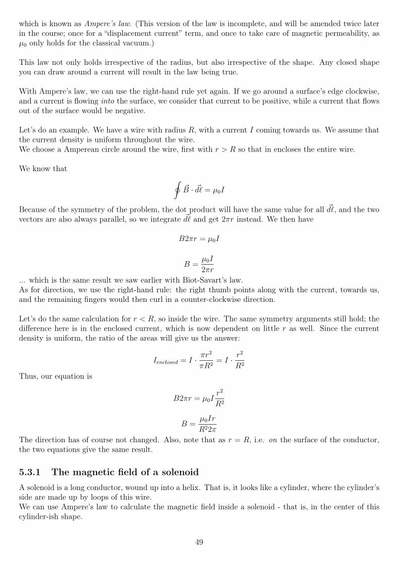
which is known as Ampere’s law. (This version of the law is incomplete, and will be amended twice laterin the course; once for a “displacement current” term, and once to take care of magnetic permeability, asµ0 only holds for the classical vacuum.)
This law not only holds irrespective of the radius, but also irrespective of the shape. Any closed shapeyou can draw around a current will result in the law being true.
With Ampere’s law, we can use the right-hand rule yet again. If we go around a surface’s edge clockwise,and a current is flowing into the surface, we consider that current to be positive, while a current that flowsout of the surface would be negative.
Let’s do an example. We have a wire with radius R, with a current I coming towards us. We assume thatthe current density is uniform throughout the wire.We choose a Amperean circle around the wire, first with r > R so that in encloses the entire wire.
We know that ∮~B · ~d` = µ0I
Because of the symmetry of the problem, the dot product will have the same value for all ~d`, and the twovectors are also always parallel, so we integrate ~d` and get 2πr instead. We then have
B2πr = µ0I
B =µ0I
2πr
... which is the same result we saw earlier with Biot-Savart’s law.As for direction, we use the right-hand rule: the right thumb points along with the current, towards us,and the remaining fingers would then curl in a counter-clockwise direction.
Let’s do the same calculation for r < R, so inside the wire. The same symmetry arguments still hold; thedifference here is in the enclosed current, which is now dependent on little r as well. Since the currentdensity is uniform, the ratio of the areas will give us the answer:
Ienclosed = I · πr2
πR2= I · r
2
R2
Thus, our equation is
B2πr = µ0Ir2
R2
B =µ0Ir
R22π
The direction has of course not changed. Also, note that as r = R, i.e. on the surface of the conductor,the two equations give the same result.
5.3.1 The magnetic field of a solenoid
A solenoid is a long conductor, wound up into a helix. That is, it looks like a cylinder, where the cylinder’sside are made up by loops of this wire.We can use Ampere’s law to calculate the magnetic field inside a solenoid - that is, in the center of thiscylinder-ish shape.
49
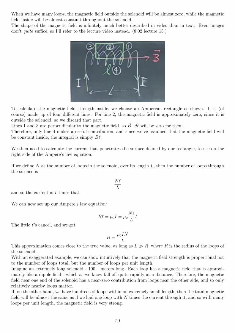
When we have many loops, the magnetic field outside the solenoid will be almost zero, while the magneticfield inside will be almost constant throughout the solenoid.The shape of the magnetic field is infinitely much better described in video than in text. Even imagesdon’t quite suffice, so I’ll refer to the lecture video instead. (8.02 lecture 15.)
To calculate the magnetic field strength inside, we choose an Amperean rectangle as shown. It is (ofcourse) made up of four different lines. For line 2, the magnetic field is approximately zero, since it isoutside the solenoid, so we discard that part.Lines 1 and 3 are perpendicular to the magnetic field, so ~B · ~d` will be zero for them.Therefore, only line 4 makes a useful contribution, and since we’ve assumed that the magnetic field willbe constant inside, the integral is simply B`.
We then need to calculate the current that penetrates the surface defined by our rectangle, to use on theright side of the Ampere’s law equation.
If we define N as the number of loops in the solenoid, over its length L, then the number of loops throughthe surface is
N`
Land so the current is I times that.
We can now set up our Ampere’s law equation:
B` = µ0I = µ0N`
LI
The little `’s cancel, and we get
B =µ0IN
LThis approximation comes close to the true value, as long as L R, where R is the radius of the loops ofthe solenoid.With an exaggerated example, we can show intuitively that the magnetic field strength is propertional notto the number of loops total, but the number of loops per unit length.Imagine an extremely long solenoid - 100+ meters long. Each loop has a magnetic field that is approxi-mately like a dipole field - which as we know fall off quite rapidly at a distance. Therefore, the magneticfield near one end of the solenoid has a near-zero contribution from loops near the other side, and so onlyrelatively nearby loops matter.If, on the other hand, we have hundreds of loops within an extremely small length, then the total magneticfield will be almost the same as if we had one loop with N times the current through it, and so with manyloops per unit length, the magnetic field is very strong.
50
Chapter 6
Week 6
6.1 Electromagnetic inductionWe have previously looked at how moving electric charges (currents) create magnetic fields. Now, we’lllook at how magnetic field can create electric fields, and thus currents in conductors.Unlike the case for electric → magnetic fields, where a steady current creates a steady magnetic field (viaBiot-Savart and Ampere’s laws), a steady magnetic field does not produce a steady current. In fact, astatic magnetic field creates no current at all; only a changing magnetic field does.
The phenomenon where a changing magnetic field causes - or induces - a current, is known as electromag-netic induction. It was discovered by Michael Faraday, who did experiments to find out whether, indeed,constant magnetic fields cause constant currents.One experiment he did involved a battery, a solenoid, a switch, and a separate loop with a current meterin series.He Usedt he first three components to create a roughly constant magnetic field, inside the solenoid. Hethen wound a loop of wire around the solenoid, and connected that to a current meter. If the hypothesiswas correct, he would have seen a steady current in the current meter whenever the solenoid was powered.That was not what happened; indeed, there was no current at all.However, he later noticed a current spike in the current meter while he was flipping the switch to thesolenoid, whether he powered it on or off, the direction of the current being dependent on which. Heconcluded that a changing magnetic field induces a current.This principle is extremely important for the modern world, as it is the basis of most of our currentpower-generation: wind power, hydropower and nuclear power all depend on Faraday’s law, as they allmake turbines spin inside magnetic fields to produce power.
6.1.1 Lenz’s law
Say we have a simple loop, i.e. a wire bent into a rectangle, a circle or such a shape. We move a bar magnetdownwards into the loop, with the magnet’s north pole first. The magnetic field of the bar magnetic willpoint downwards, into the loop, and will be increasing as we move in closer.There will be a induced current in the loop, such that the current’s magnetic field opposes the magneticfield of the bar magnet. Via the right-hand rule, if the current’s magnetic field is field pointing upwards,the current is flowing counterclockwise as seen from above.If we pull the bar magnet upwards, the external (the bar magnet’s) B field will be going down in the loop,and so the current will be in the opposite direction.
The fact that the current’s field will always oppose the external field change is known as Lenz’s law. Itstates nothing more than the current’s direction - to calculate the current’s magnitude, we must use Fara-day’s law, soon to be introduced.
51
Clearly, a current cannot just come about on its own - a current is usually driven by a source, that producesa potential difference over e.g. a wire. In this case, it is an induced EMF due to the changing magneticfield, which can be written as
Eind = IindR
... which is of course just Ohm’s law. R is this case, then, is the total resistance of the entire loop wherethe current flows.
In another experiment by Faraday, he had a current loop connected to a battery, that created a magneticfield. He switched the current, such that the magnetic field was changing (since, as we now know, a staticmagnetic field produces no EMF).He then had a second loop, with no battery, independent from the first, but located nearby, such that thechanging magnetic field affects the second loop.What he found was that the induced EMF in loop number two was proportional to the change in themagnetic field from the first,
E2 ∝dB1
dt
... and also that it was proportional to the area of the second loop. This gave him the idea that perhapsthe EMF is proportional to the change in magnetic flux through the surface of the loop.
6.1.2 Magnetic flux
Magnetic flux is defined in the same way as electric flux, except of course that the dot product is betweenthe magnetic field and an area vector.
That is, for an open surface A, and a magnetic field B, we integrate the dot product of all infinitesimalarea vectors ~dA on the surface with the local magnetic field at that point. This gives us the magnetic fluxφB (or ΦB - the Greek letters being lowercase and uppercase phi, respectively):
ΦB =
∫~B · ~dA
This integral is done over the open surface where we want to know the flux.The SI unit of magnetic flux is the weber (Wb); 1 Wb = 1 T ·m2.
When the B-field is constant and through a planar surface, this simplifies down to
ΦB = BA cos θ
... where θ is the angle between the magnetic field and the unit normal perpendicular to the surface.
For electric flux, we have Gauss’s law, which relates the flux through a closed surface to the amount ofcharge inside:
ΦE =
∮~E · ~dA =
Qencl
ε0
If we enclose a single electric charge (an electric monopole), whether positive or negative, the flux is alwaysnonzero.If we enclose an electric dipole, such that we enclose the entire dipole, the flux will be zero. However, ifwe choose the closed surface such that in encloses only part of the dipole, the flux will again be nonzero.The electric field lines always begin at the positive charge(s) and end on the negative charge(s).
52
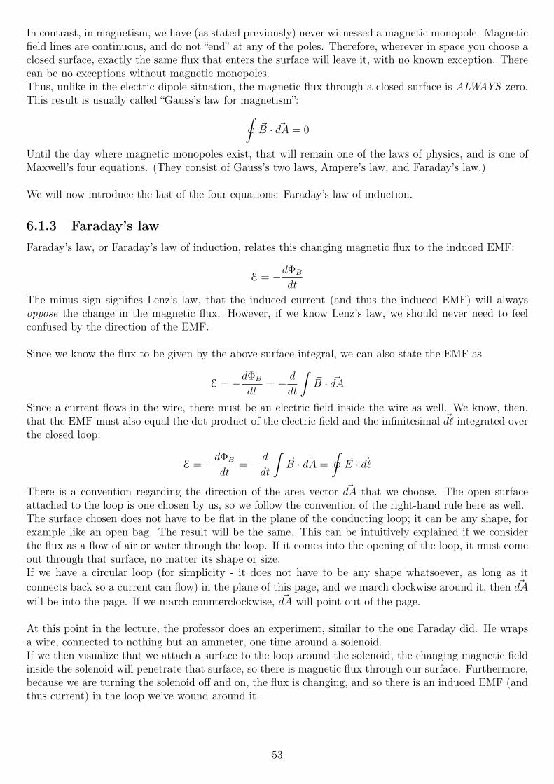
In contrast, in magnetism, we have (as stated previously) never witnessed a magnetic monopole. Magneticfield lines are continuous, and do not “end” at any of the poles. Therefore, wherever in space you choose aclosed surface, exactly the same flux that enters the surface will leave it, with no known exception. Therecan be no exceptions without magnetic monopoles.Thus, unlike in the electric dipole situation, the magnetic flux through a closed surface is ALWAYS zero.This result is usually called “Gauss’s law for magnetism”:∮
~B · ~dA = 0
Until the day where magnetic monopoles exist, that will remain one of the laws of physics, and is one ofMaxwell’s four equations. (They consist of Gauss’s two laws, Ampere’s law, and Faraday’s law.)
We will now introduce the last of the four equations: Faraday’s law of induction.
6.1.3 Faraday’s law
Faraday’s law, or Faraday’s law of induction, relates this changing magnetic flux to the induced EMF:
E = −dΦB
dt
The minus sign signifies Lenz’s law, that the induced current (and thus the induced EMF) will alwaysoppose the change in the magnetic flux. However, if we know Lenz’s law, we should never need to feelconfused by the direction of the EMF.
Since we know the flux to be given by the above surface integral, we can also state the EMF as
E = −dΦB
dt= − d
dt
∫~B · ~dA
Since a current flows in the wire, there must be an electric field inside the wire as well. We know, then,that the EMF must also equal the dot product of the electric field and the infinitesimal ~d` integrated overthe closed loop:
E = −dΦB
dt= − d
dt
∫~B · ~dA =
∮~E · ~d`
There is a convention regarding the direction of the area vector ~dA that we choose. The open surfaceattached to the loop is one chosen by us, so we follow the convention of the right-hand rule here as well.The surface chosen does not have to be flat in the plane of the conducting loop; it can be any shape, forexample like an open bag. The result will be the same. This can be intuitively explained if we considerthe flux as a flow of air or water through the loop. If it comes into the opening of the loop, it must comeout through that surface, no matter its shape or size.If we have a circular loop (for simplicity - it does not have to be any shape whatsoever, as long as itconnects back so a current can flow) in the plane of this page, and we march clockwise around it, then ~dA
will be into the page. If we march counterclockwise, ~dA will point out of the page.
At this point in the lecture, the professor does an experiment, similar to the one Faraday did. He wrapsa wire, connected to nothing but an ammeter, one time around a solenoid.If we then visualize that we attach a surface to the loop around the solenoid, the changing magnetic fieldinside the solenoid will penetrate that surface, so there is magnetic flux through our surface. Furthermore,because we are turning the solenoid off and on, the flux is changing, and so there is an induced EMF (andthus current) in the loop we’ve wound around it.
53
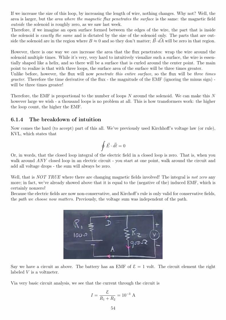
If we increase the size of this loop, by increasing the length of wire, nothing changes. Why not? Well, thearea is larger, but the area where the magnetic flux penetrates the surface is the same: the magnetic fieldoutside the solenoid is roughly zero, as we saw last week.Therefore, if we imagine an open surface formed between the edges of the wire, the part that is insidethe solenoid is exactly the same and is dictated by the size of the solenoid only. The parts that are out-side the solenoid are in the region where B ≈ 0 and so they don’t matter; ~B · ~dA will be zero in that region.
However, there is one way we can increase the area that the flux penetrates: wrap the wire around thesolenoid multiple times. While it’s very, very hard to intuitively visualize such a surface, the wire is essen-tially shaped like a helix, and so there will be a surface that is curled around the center point. The mainpoint to realize is that with three loops, the surface area of the surface will be three times greater.Unlike before, however, the flux will now penetrate this entire surface, so the flux will be three timesgraeter. Therefore the time derivative of the flux - the magnitude of the EMF (ignoring the minus sign) -will be three times greater!
Therefore, the EMF is proportional to the number of loops N around the solenoid. We can make this Nhowever large we wish - a thousand loops is no problem at all. This is how transformers work: the higherthe loop count, the higher the EMF.
6.1.4 The breakdown of intuition
Now comes the hard (to accept) part of this all. We’ve previously used Kirchhoff’s voltage law (or rule),KVL, which states that ∮
~E · ~d` = 0
Or, in words, that the closed loop integral of the electric field in a closed loop is zero. That is, when youwalk around ANY closed loop in an electric circuit - you start at one point, walk around the circuit andadd all voltage drops - the sum will always be zero.
Well, that is NOT TRUE where there are changing magnetic fields involved! The integral is not zero anymore; in fact, we’ve already showed above that it is equal to the (negative of the) induced EMF, which iscertainly nonzero!Because the electric fields are now non-conservative, and Kirchoff’s rule is only valid for conservative fields,the path we choose now matters. Previously, the voltage sum was independent of the path.
Say we have a circuit as above. The battery has an EMF of E = 1 volt. The circuit element the rightlabeled V is a voltmeter.
Via very basic circuit analysis, we see that the current through the circuit is
I =E
R1 +R2
= 10−3 A
54
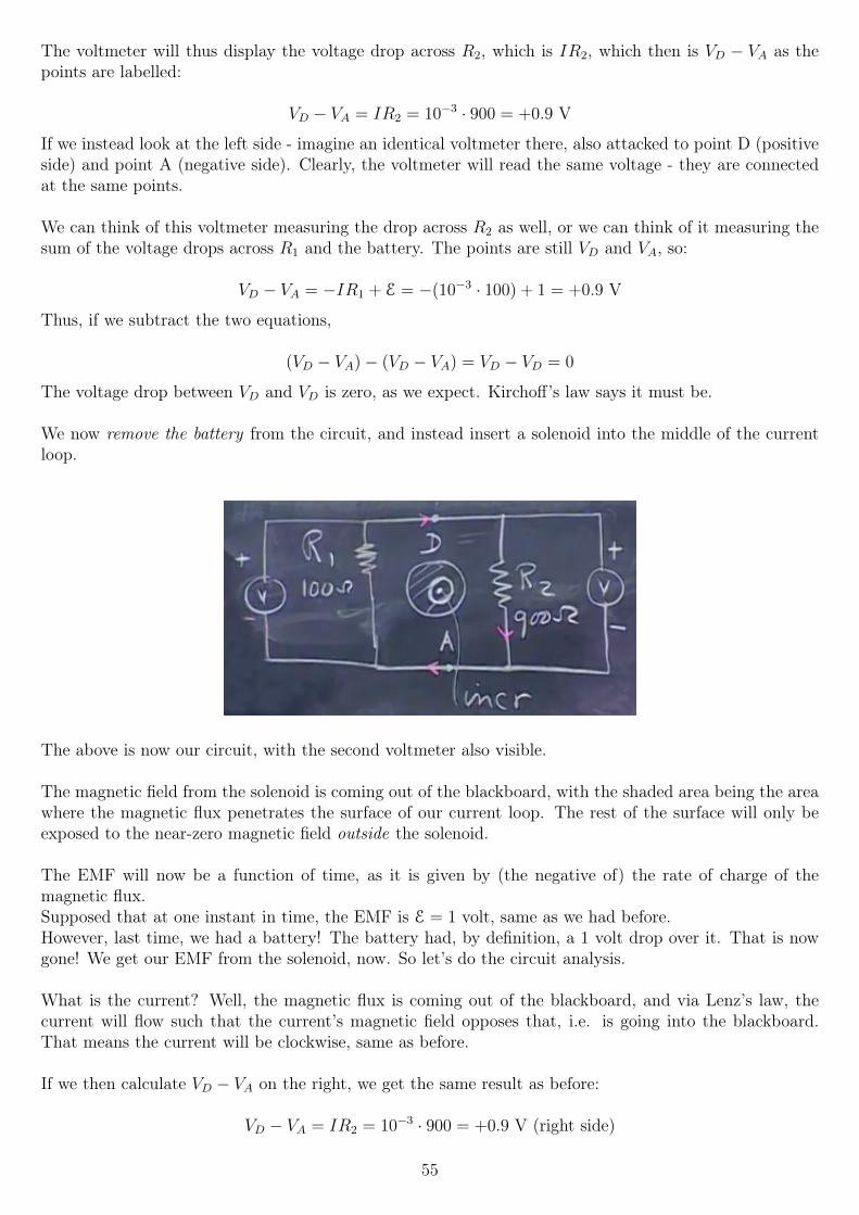
The voltmeter will thus display the voltage drop across R2, which is IR2, which then is VD − VA as thepoints are labelled:
VD − VA = IR2 = 10−3 · 900 = +0.9 V
If we instead look at the left side - imagine an identical voltmeter there, also attacked to point D (positiveside) and point A (negative side). Clearly, the voltmeter will read the same voltage - they are connectedat the same points.
We can think of this voltmeter measuring the drop across R2 as well, or we can think of it measuring thesum of the voltage drops across R1 and the battery. The points are still VD and VA, so:
VD − VA = −IR1 + E = −(10−3 · 100) + 1 = +0.9 V
Thus, if we subtract the two equations,
(VD − VA)− (VD − VA) = VD − VD = 0
The voltage drop between VD and VD is zero, as we expect. Kirchoff’s law says it must be.
We now remove the battery from the circuit, and instead insert a solenoid into the middle of the currentloop.
The above is now our circuit, with the second voltmeter also visible.
The magnetic field from the solenoid is coming out of the blackboard, with the shaded area being the areawhere the magnetic flux penetrates the surface of our current loop. The rest of the surface will only beexposed to the near-zero magnetic field outside the solenoid.
The EMF will now be a function of time, as it is given by (the negative of) the rate of charge of themagnetic flux.Supposed that at one instant in time, the EMF is E = 1 volt, same as we had before.However, last time, we had a battery! The battery had, by definition, a 1 volt drop over it. That is nowgone! We get our EMF from the solenoid, now. So let’s do the circuit analysis.
What is the current? Well, the magnetic flux is coming out of the blackboard, and via Lenz’s law, thecurrent will flow such that the current’s magnetic field opposes that, i.e. is going into the blackboard.That means the current will be clockwise, same as before.
If we then calculate VD − VA on the right, we get the same result as before:
VD − VA = IR2 = 10−3 · 900 = +0.9 V (right side)
55
What about the left side? Well, the battery is now gone, so the result is the same as before, minus theplus one:
VD − VA = −IR1 = −(10−3 · 100) = −0.91 V (left side)
VD − VA has two different values, depending on which path we choose to measure it! The twovoltmeter are connected to the same points, but show different values! Extremely nonintuitive.
This also means, then, that Kirchoff’s voltage “law” has been broken: the sum around the loop is not zero!
VD − VA = +0.9 V (right side)
VD − VA = −0.1 V (left side)
(VD − VA)− (VD − VA) = VD − VD = +1 V
Note that this is all at one instant in time; the result is not because the values somehow changed duringthe calculation. It’s just an extremely nonintuitive result that can be very hard to accept as being correct.
6.2 Motional EMF and dynamosWe have seen now that the induced EMF is related to the change in magnetic flux through a surface.Suppose that we have a rectangular current loop of sides x and y. We assign the area vector infinitesimal~dA to it, such that ~dA points upwards.We then have a uniform magnetic field ~B pointing upwards, but at an angle towards the right.The angle between ~dA and ~B is θ.
The flux through the surface is then given by BA cos θ. A = xy, so
ΦB = xyB cos θ
The induced EMF is then given by the time derivative of this expression. However, note that there are
three things which can change over time: the magnetic field, so we havedB
dt; the area, so we have
dA
dt,
and the angle between them θ, so we havedθ
dt. That is, if θ is changing, we are rotating the conducting
loop inside the uniform magnetic field.
Consider rotating this about the y axis, centered on the loop. We rotate it with angular frequency ω,which is given by 2π divided by the period T :
ω =2π
T= 2πf
... which is, as above, equal to 2π times the rotational frequency in hertz.(The unit of ω is given as radians per second, rad/s; however radians are dimensionless, and so it is reallyequivalent to hertz, s−1; to not confuse values of angular frequency with frequency, we consider the latterto be in radians/second.)
The angle θ will then become θ0 + ωt, where θ0 is the angle at t = 0. We can choose that to be 0, so thatθ = ωt. Thus, we have
ΦB = AB cosωt
The EMF is given by the negative of the derivative of that, so
dΦB
dt= ABω(− sinωt)
56
The EMF is the negative of the above, so the minus sign from the cosine derivative cancels:
E(t) = ABω sinωt
Keep in mind that A is the total surface area the flux penetrates! If you have a loop of N > 1 windingsin a shape of area A, the EMF is given by
E(t) = NAone Bω sinωt
... with Aone being the area of one winding.
The current in the loop will then also be time dependent, and it will alternate in the sinusoidal fashionseen above; this makes it alternating current, the same stuff that comes out of your wall.The reason AC is used there will be touched upon later in the course; one big reason is that transformerscan be used to convert AC voltages up to the high voltages in power lines, to avoid losses, and then backdown to the approximately 100 to 250 volts used in homes around the world.Another is that power generated by generators/turbines/dynamos is sinusoidal by its nature, see below.
Let’s talk about about generators, turbines or dynamos - whatever you prefer. If we have permanentmagnet, and we rotate conducting windings inside that magnetic field, we get an EMF as seen above. Thisis the process used for most of our power generation - wind power, hydropower and indeed nuclear powerall drive turbines to generate electricity.The stronger the magnetic field, the higher the EMF. The more windings, the higher the EMF. The largerthe area, the higher the EMF. And lastly, the faster you rotate it, the higher the EMF.The last point is useless for the power grid, however: the power grid has a fixed frequency, usually of 50Hz (in Europe, Africa, Australia and most of the world) or 60 Hz (in the US and Americas, though notall of it).If we were to increase ω, then, not only would the EMF increase, but the power would be out of sync withthe rest of the power grid, which would cause big problems.One of the relatively smaller such problems is that many devices - some clocks, for example - use the linefrequency to keep track of time. Thus, a clock designed for 50 Hz may go 20% too fast if the line frequencyin 60 Hz. (Or it may not, depending on how it keeps time.)
Because power is given by P = V I =V 2
R= I2R, and both V and I alone increase linearly with ω, the
power increases (or decreases) with ω2 as we change it.
6.2.1 Changing the area
We have now looked at changing the magnetic field and changing θ. What about changing the area of theloop, such that the flux through it changes that way?
Imagine we have a rectangular loop of sides x and `. The right side, of length `, is a crossbar; we can moveit towards the left and right, such that x changes with time. We then have a velocity vector ~v towards theright (or left, when it is negative). Say we have a uniform magnetic field ~B going upwards.
The flux through the surface is then
ΦB = `xB
We then take the time derivative of this, where x is the variable that changes with time, while ` and Bare constant:
57
dΦB
dt= `B
dx
dt
However,dx
dtis simply the speed (or velocity, if we attach a direction of +x to it) of the crossbar. The
EMF is then, via Faraday’s law:
|E| = `B|~v|
“The resistance of the conducting loop is R. What is the power dissipated by the circuit?”
Power is P =V 2
R, where V = E for this case. We found E above, so the answer is
E2
R=`2B2v2
R
“What is the magnitude of the force experienced by the moving part of the loop?”
We found before that the force on a current-carrying wire can be found via
~FB =
∫wire
I(~d`× ~B)
Since ~d` and ~B are exactly perpendicular in this problem, the integral simplifies down to
~FB = I`B
... where ` is the length of the wire segment.
I =E
R=`vB
R
We substitute that into the force equation and get another ` and B, so the answer is
~FB =`2vB2
R
The direction of this force is to the left: ~d` × ~B gives the direction, where ~d` is an infinitesimal wiresegment the current moves through. That vector is “upwards” (+y, in our 2D plane), and the B-field isperpendicular to that, upwards “in 3D” (+z).
“How much power is needed to keep the bar moving at constant velocity?”
Power is work per unit time, so the time derivative of work should give us the answer. We know themagetic force, which is to the left. So we need to exert a force towards the right, of equal magnitude. Thework we do is then that force (that we have above) times the distance. We then need to take the timederivative of that.However, we already have the time derivative of the displacement - the velocity. So
P = ~FB · ~v
Since they are in exactly opposite directions, cos θ = 1, so the answer is the answer for the force above,times another v:
P =`2v2B2
R
58
... which happens to exactly the same as the power dissipated by the circuit! Of course, unless we findsomewhere else the power could be used, this is to be expected; energy can’t be created nor destroyed.The power we put in must go somewhere.
We can also write this in terms of I instead:
P = I`Bv
This must be equal to the EMF times the current; the current then cancels from the equation, and we get
|E| = `Bv
... which is what we found earlier, however this time we did not use Faraday’s law to find it, merely thework per unit time we do to move the crossbar against the magnetic force.
Also, note that if instead of pulling towards the right, we push the crossbar towards the left. We still doexactly the same amount of work - positive work in both cases. When ~v is flipped over, the magnetic forceis also flipped over, because the current reverses direction as the magnetic flux is now decreasing.
6.2.2 Eddy currents
Let’s now move our focus to something different, but related.Suppose we move a solid, conductive disk through a magnetic field. Say we have magnetic field pointingupwards, and we move the disk through it sideways.We know that the changing magnetic flux through the disk will induce a current to oppose the magneticflux change; that is, the current’s magnetic field will be downwards, and so via the right-hand rule, thecurrent will be clockwise.We call these currents eddy currents.They produce heat in the conductor; the energy for that must come from somewhere. In this case, energythat would otherwise be kinetic energy is used up, and so the disk slows down. This is the principle calledmagnetic braking.
Eddy current calculation
A fairly hefty question was in between the lecture videos, so I’ll write down how I solved it. If it weren’tfor the multiple-choice answers, this would make a good homework question!
“A rectangular loop of wire with massm, width w, vertical length `, and resistance R falls out of a magneticfield under the influence of gravity. The magnetic field is uniform and out of the paper ( ~B = Bx) withinthe area shown (see sketch) and zero outside of that area. At the time shown in the sketch, the loop isexiting the magnetic field at velocity ~v(t) = v(t)~z, where v(t)<0 (meaning the loop is moving downward,not upward). Suppose at time t the distance from the top of the loop to the point where the magneticfield goes to zero is z(t) (see sketch).”
59
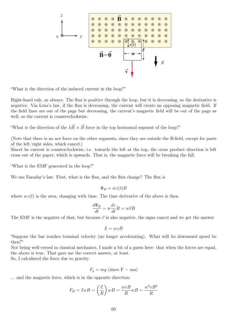
“What is the direction of the induced current in the loop?”
Right-hand rule, as always. The flux is positive through the loop, but it is decreasing, so the derivative isnegative. Via Lenz’s law, if the flux is decreasing, the current will create an opposing magnetic field. Ifthe field lines are out of the page but decreasing, the current’s magnetic field will be out of the page aswell, so the current is counterclockwise.
“What is the direction of the I ~d`× ~B force in the top horizontal segment of the loop?”
(Note that there is no net force on the other segments, since they are outside the B-field, except for partsof the left/right sides, which cancel.)Sincet he current is counterclockwise, i.e. towards the left at the top, the cross product direction is leftcross out of the paper, which is upwards. That is, the magnetic force will be breaking the fall.
“What is the EMF generated in the loop?”
We use Faraday’s law. First, what is the flux, and the flux change? The flux is
ΦB = wz(t)B
where wz(t) is the area, changing with time. The time derivative of the above is then
dΦB
dt= w
dz
dtB = w~vB
The EMF is the negative of that, but because ~v is also negative, the signs cancel and we get the answer
E = wvB
“Suppose the bar reaches terminal velocity (no longer accelerating). What will its downward speed bethen?”Not being well-versed in classical mechanics, I made a bit of a guess here: that when the forces are equal,the above is true. That gave me the correct answer, at least.So, I calculated the force due to gravity:
Fg = mg (since F = ma)
... and the magnetic force, which is in the opposite direction:
FB = IwB =
(E
R
)wB =
wvB
RwB =
w2vB2
R
60
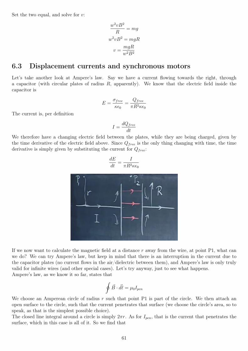
Set the two equal, and solve for v:
w2vB2
R= mg
w2vB2 = mgR
v =mgR
w2B2
6.3 Displacement currents and synchronous motorsLet’s take another look at Ampere’s law. Say we have a current flowing towards the right, througha capacitor (with circular plates of radius R, apparently). We know that the electric field inside thecapacitor is
E =σfreeκε0
=Qfree
πR2κε0
The current is, per definition
I =dQfree
dt
We therefore have a changing electric field between the plates, while they are being charged, given bythe time derivative of the electric field above. Since Qfree is the only thing changing with time, the timederivative is simply given by substituting the current for Qfree:
dE
dt=
I
πR2κε0
If we now want to calculate the magnetic field at a distance r away from the wire, at point P1, what canwe do? We can try Ampere’s law, but keep in mind that there is an interruption in the current due tothe capacitor plates (no current flows in the air/dielectric between them), and Ampere’s law is only trulyvalid for infinite wires (and other special cases). Let’s try anyway, just to see what happens.Ampere’s law, as we know it so far, states that∮
~B · ~d` = µ0Ipen
We choose an Amperean circle of radius r such that point P1 is part of the circle. We then attach anopen surface to the circle, such that the current penetrates that surface (we choose the circle’s area, so tospeak, as that is the simplest possible choice).The closed line integral around a circle is simply 2πr. As for Ipen, that is the current that penetrates thesurface, which in this case is all of it. So we find that
61
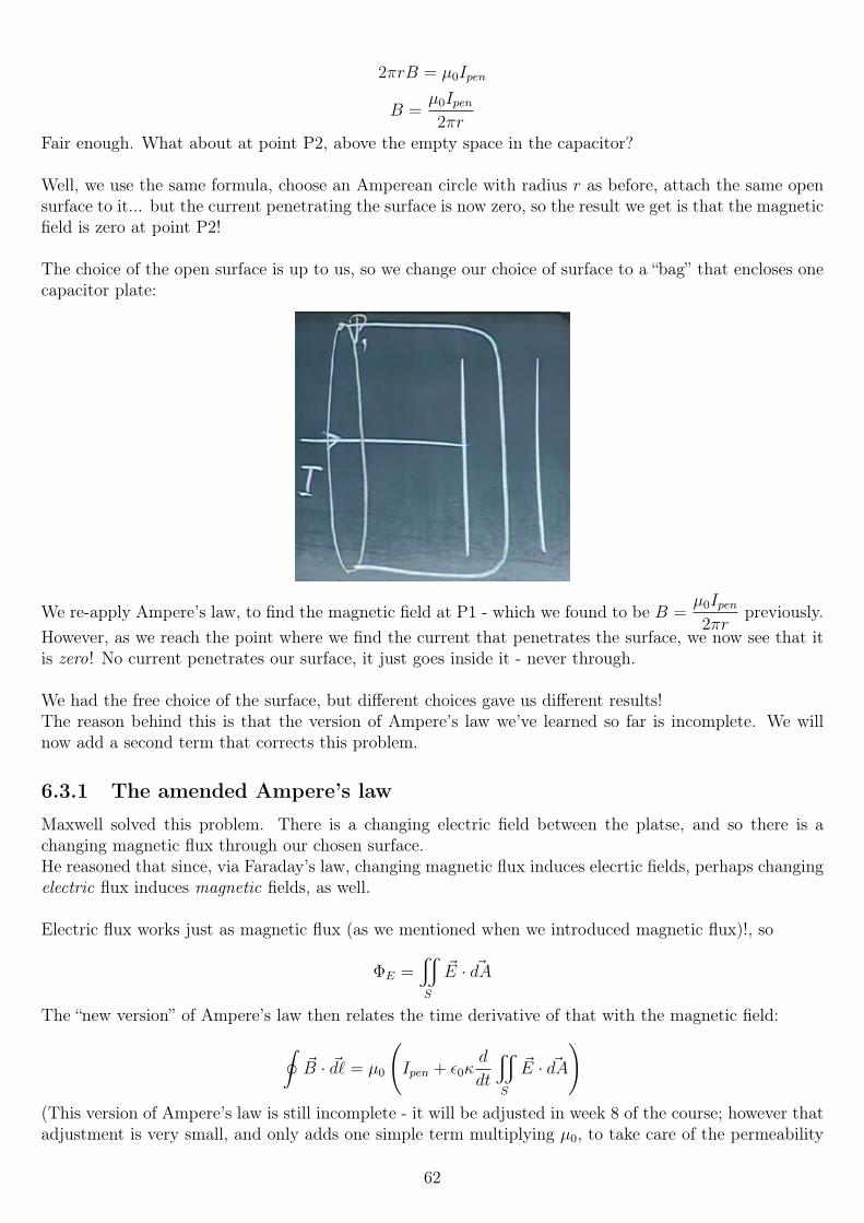
2πrB = µ0Ipen
B =µ0Ipen2πr
Fair enough. What about at point P2, above the empty space in the capacitor?
Well, we use the same formula, choose an Amperean circle with radius r as before, attach the same opensurface to it... but the current penetrating the surface is now zero, so the result we get is that the magneticfield is zero at point P2!
The choice of the open surface is up to us, so we change our choice of surface to a “bag” that encloses onecapacitor plate:
We re-apply Ampere’s law, to find the magnetic field at P1 - which we found to be B =µ0Ipen2πr
previously.However, as we reach the point where we find the current that penetrates the surface, we now see that itis zero! No current penetrates our surface, it just goes inside it - never through.
We had the free choice of the surface, but different choices gave us different results!The reason behind this is that the version of Ampere’s law we’ve learned so far is incomplete. We willnow add a second term that corrects this problem.
6.3.1 The amended Ampere’s law
Maxwell solved this problem. There is a changing electric field between the platse, and so there is achanging magnetic flux through our chosen surface.He reasoned that since, via Faraday’s law, changing magnetic flux induces elecrtic fields, perhaps changingelectric flux induces magnetic fields, as well.
Electric flux works just as magnetic flux (as we mentioned when we introduced magnetic flux)!, so
ΦE =x
S
~E · ~dA
The “new version” of Ampere’s law then relates the time derivative of that with the magnetic field:∮~B · ~d` = µ0
(Ipen + ε0κ
d
dt
x
S
~E · ~dA
)(This version of Ampere’s law is still incomplete - it will be adjusted in week 8 of the course; however thatadjustment is very small, and only adds one simple term multiplying µ0, to take care of the permeability
62
of other media than the classical vacuum.)
The closed loop in the first integral is then the Amperean circle, while the surface in the second (surface)integral is the open surface attached to that closed loop. That is, the closed loop is the opening of thebag, while the open surface is the bag’s surface.
The current Ipen is the “real” current that penetrates the surface. The second term, ε0κd
dt
x
S
~E · ~dA, is
called the displacement current.
Note that whenever the electric flux is constant, the time derivative goes to zero, and the “old” Ampere’slaw pops out.
Let’s try to re-calculate the magnetic field at P1, again using both the flat surface and the “bag”. Firstout is the flat surface.
The left-hand side of the equation is unchanged, so 2πrB, while the right-hand side turns out like this:
2πrB = µ0
(Ipen + ε0κ
d
dt
(~0πr2
))= µ0 (Ipen + 0)
... because there is no electric flux penetrating the surface - it is outside the capacitor, where the electricfield due to the capacitor is zero.
Thus, we find
B =µ0Ipen2πr
Same as before.
We re-start with: ∮~B · ~d` = µ0
(Ipen + ε0κ
d
dt
x
S
~E · ~dA
)The left-hand side is unchanged, as that is the closed Amperean loop, which we are not changing. Ipennow changes, however: it is again zero - once again, no current penetrates the surface! What about thesecond term? Let’s fill it in:
2πrB = µ0ε0κd
dt
(EπR2
)The E-field is what is changing with time, so we put that in there (we found
dE
dtearlier):
2πrB = µ0ε0κdE
dtπR2 = µ0ε0κ
I
πR2κε0πR2
Note that the I here is not Ipen, the current penetrating the surface we’ve chosen, but the current in thewire. It is not zero!
If we simplify this, we get
B =µ0I
2πr
Excellent! Though we found I in a very different way, the answer is identical!
63
Next up, let’s try to calculate the B-field inside the capacitor (while it is charging; when it is not, we havean electrostatic situation and it ought to be zero).
We set a new point P2 at distance r from the exact center of the capacitor (in all dimensions). Since thechoice of surface should not matter, we will make it simple an pick the flat surface again.
2πrB = µ0
(Ipen + ε0κ
d
dt
x
S
~E · ~dA
)Ipen is zero, since there is no current inside - only air (or dielectric)! The flux, however, is EA with the areabeing πr2 (little r - the surface is smaller than the plates, so there is no contribution from the remainingarea).
2πrB = µ0ε0κd
dt
(Eπr2
)Again, we know the time derivative of the E-field from earlier, so we substitute that in there once again:
2πrB = µ0ε0κI
πR2κε0πr2
B =µ0Ir
2πR2(for r < R)
Interesting, it is exactly zero in the middle (r = 0), then, and greatest at the edge.
6.3.2 Displacement current
Why did Maxwell call the second term the “displacement current”?If you have a dielectric between the capacitor plates, the changing electric fields will cause a current;the induced charges will be rearranged due to the changing electric fields. In a vacuum, however, thereshouldn’t be a current, so the name is perhaps somewhat poorly chosen.
“We have a capacitor of area A filled with a dielectric slab with dielectric constant κ. If Q(t) is a functionof time, what is the polarization current in the dielectric? Express your answer in terms of the magnitudeof the electric field E(t) between the plates. Positive polarization current flows down in the picture.”The picture is then of a simple capacitor, with +Q on the top plate and −Q on the bottom, with theopposite induced charges Qind on the dielectric (minus up, plus down).
Hmm, OK. E(t) is given by
E(t) =σ(t)
κε0=Q(t)
κε0A
My first thought was to solve for Q and take the time derivative of both sides. That didn’t work; I gotsomething close to the correct answer, yet far away: it had a factor κ instead of (κ − 1), where as we’llsee, only the latter means no current if κ = 1 (for a perfect vacuum).
Instead, we can solve it like this:First, we know that the E-field in a capacitor in a vacuum is
Evacuum(t) =σ(t)
ε0=Q(t)
ε0A
With a dielectric, there will be an induced charge Qind(t) on the dielectric. This induced charge causes anopposing electric field, Eind(t), which causes E(t) to equal the original E-field divided by κ:
64
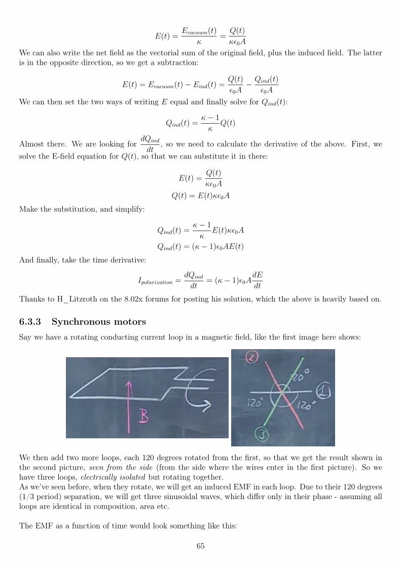
E(t) =Evacuum(t)
κ=Q(t)
κε0A
We can also write the net field as the vectorial sum of the original field, plus the induced field. The latteris in the opposite direction, so we get a subtraction:
E(t) = Evacuum(t)− Eind(t) =Q(t)
ε0A− Qind(t)
ε0A
We can then set the two ways of writing E equal and finally solve for Qind(t):
Qind(t) =κ− 1
κQ(t)
Almost there. We are looking fordQind
dt, so we need to calculate the derivative of the above. First, we
solve the E-field equation for Q(t), so that we can substitute it in there:
E(t) =Q(t)
κε0A
Q(t) = E(t)κε0A
Make the substitution, and simplify:
Qind(t) =κ− 1
κE(t)κε0A
Qind(t) = (κ− 1)ε0AE(t)
And finally, take the time derivative:
Ipolarization =dQind
dt= (κ− 1)ε0A
dE
dt
Thanks to H_Litzroth on the 8.02x forums for posting his solution, which the above is heavily based on.
6.3.3 Synchronous motors
Say we have a rotating conducting current loop in a magnetic field, like the first image here shows:
We then add two more loops, each 120 degrees rotated from the first, so that we get the result shown inthe second picture, seen from the side (from the side where the wires enter in the first picture). So wehave three loops, electrically isolated but rotating together.As we’ve seen before, when they rotate, we will get an induced EMF in each loop. Due to their 120 degrees(1/3 period) separation, we will get three sinusoidal waves, which differ only in their phase - assuming allloops are identical in composition, area etc.
The EMF as a function of time would look something like this:
65
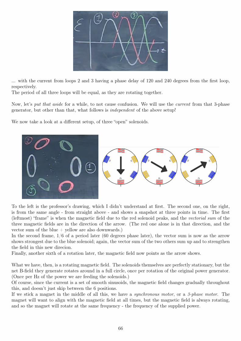
... with the current from loops 2 and 3 having a phase delay of 120 and 240 degrees from the first loop,respectively.The period of all three loops will be equal, as they are rotating together.
Now, let’s put that aside for a while, to not cause confusion. We will use the current from that 3-phasegenerator, but other than that, what follows is independent of the above setup!
We now take a look at a different setup, of three “open” solenoids.
To the left is the professor’s drawing, which I didn’t understand at first. The second one, on the right,is from the same angle - from straight above - and shows a snapshot at three points in time. The first(leftmost) “frame” is when the magnetic field due to the red solenoid peaks, and the vectorial sum of thethree magnetic fields are in the direction of the arrow. (The red one alone is in that direction, and thevector sum of the blue + yellow are also downwards.)In the second frame, 1/6 of a period later (60 degrees phase later), the vector sum is now as the arrowshows strongest due to the blue solenoid; again, the vector sum of the two others sum up and to strengthenthe field in this new direcion.Finally, another sixth of a rotation later, the magnetic field now points as the arrow shows.
What we have, then, is a rotating magnetic field. The solenoids themselves are perfectly stationary, but thenet B-field they generate rotates around in a full circle, once per rotation of the original power generator.(Once per Hz of the power we are feeding the solenoids.)Of course, since the current is a set of smooth sinusoids, the magnetic field changes gradually throughoutthis, and doesn’t just skip between the 6 positions.If we stick a magnet in the middle of all this, we have a synchronous motor, or a 3-phase motor. Themagnet will want to align with the magnetic field at all times, but the magnetic field is always rotating,and so the magnet will rotate at the same frequency - the frequency of the supplied power.
66
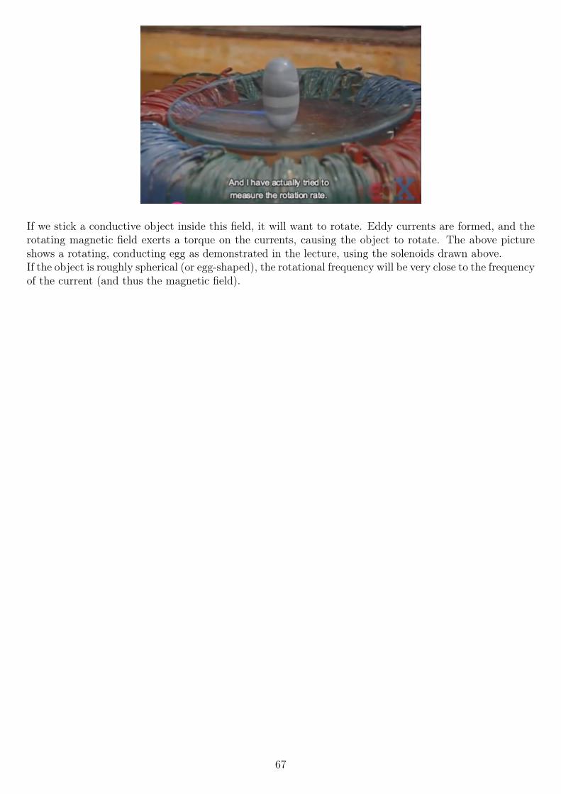
If we stick a conductive object inside this field, it will want to rotate. Eddy currents are formed, and therotating magnetic field exerts a torque on the currents, causing the object to rotate. The above pictureshows a rotating, conducting egg as demonstrated in the lecture, using the solenoids drawn above.If the object is roughly spherical (or egg-shaped), the rotational frequency will be very close to the frequencyof the current (and thus the magnetic field).
67
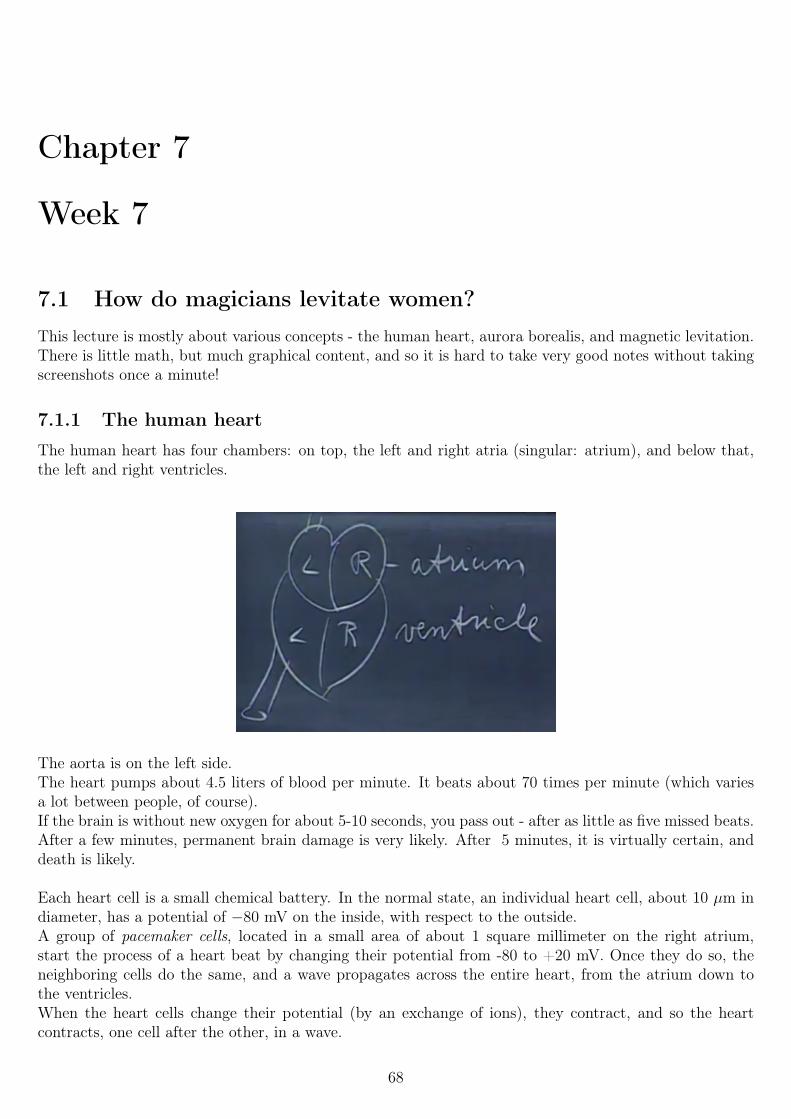
Chapter 7
Week 7
7.1 How do magicians levitate women?This lecture is mostly about various concepts - the human heart, aurora borealis, and magnetic levitation.There is little math, but much graphical content, and so it is hard to take very good notes without takingscreenshots once a minute!
7.1.1 The human heart
The human heart has four chambers: on top, the left and right atria (singular: atrium), and below that,the left and right ventricles.
The aorta is on the left side.The heart pumps about 4.5 liters of blood per minute. It beats about 70 times per minute (which variesa lot between people, of course).If the brain is without new oxygen for about 5-10 seconds, you pass out - after as little as five missed beats.After a few minutes, permanent brain damage is very likely. After 5 minutes, it is virtually certain, anddeath is likely.
Each heart cell is a small chemical battery. In the normal state, an individual heart cell, about 10 µm indiameter, has a potential of −80 mV on the inside, with respect to the outside.A group of pacemaker cells, located in a small area of about 1 square millimeter on the right atrium,start the process of a heart beat by changing their potential from -80 to +20 mV. Once they do so, theneighboring cells do the same, and a wave propagates across the entire heart, from the atrium down tothe ventricles.When the heart cells change their potential (by an exchange of ions), they contract, and so the heartcontracts, one cell after the other, in a wave.
68
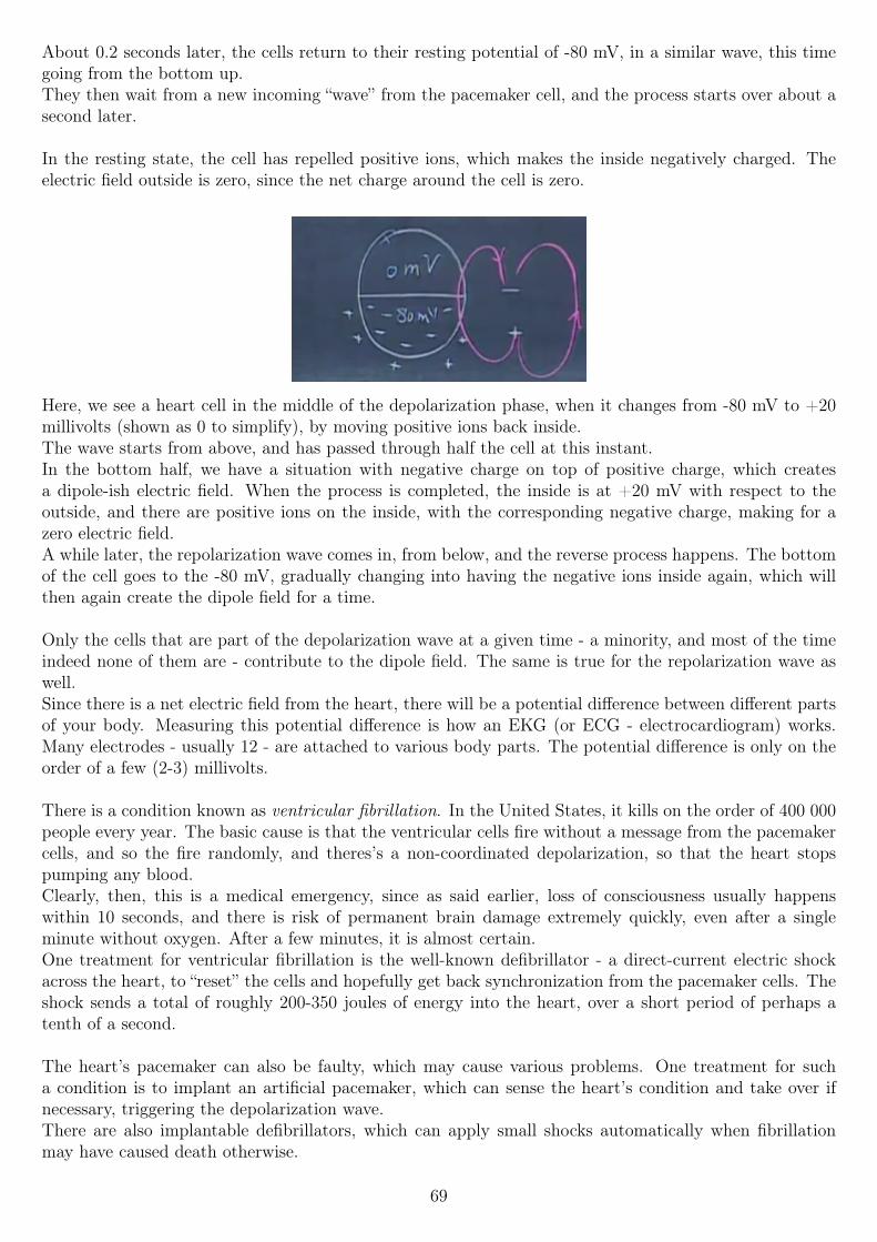
About 0.2 seconds later, the cells return to their resting potential of -80 mV, in a similar wave, this timegoing from the bottom up.They then wait from a new incoming “wave” from the pacemaker cell, and the process starts over about asecond later.
In the resting state, the cell has repelled positive ions, which makes the inside negatively charged. Theelectric field outside is zero, since the net charge around the cell is zero.
Here, we see a heart cell in the middle of the depolarization phase, when it changes from -80 mV to +20millivolts (shown as 0 to simplify), by moving positive ions back inside.The wave starts from above, and has passed through half the cell at this instant.In the bottom half, we have a situation with negative charge on top of positive charge, which createsa dipole-ish electric field. When the process is completed, the inside is at +20 mV with respect to theoutside, and there are positive ions on the inside, with the corresponding negative charge, making for azero electric field.A while later, the repolarization wave comes in, from below, and the reverse process happens. The bottomof the cell goes to the -80 mV, gradually changing into having the negative ions inside again, which willthen again create the dipole field for a time.
Only the cells that are part of the depolarization wave at a given time - a minority, and most of the timeindeed none of them are - contribute to the dipole field. The same is true for the repolarization wave aswell.Since there is a net electric field from the heart, there will be a potential difference between different partsof your body. Measuring this potential difference is how an EKG (or ECG - electrocardiogram) works.Many electrodes - usually 12 - are attached to various body parts. The potential difference is only on theorder of a few (2-3) millivolts.
There is a condition known as ventricular fibrillation. In the United States, it kills on the order of 400 000people every year. The basic cause is that the ventricular cells fire without a message from the pacemakercells, and so the fire randomly, and theres’s a non-coordinated depolarization, so that the heart stopspumping any blood.Clearly, then, this is a medical emergency, since as said earlier, loss of consciousness usually happenswithin 10 seconds, and there is risk of permanent brain damage extremely quickly, even after a singleminute without oxygen. After a few minutes, it is almost certain.One treatment for ventricular fibrillation is the well-known defibrillator - a direct-current electric shockacross the heart, to “reset” the cells and hopefully get back synchronization from the pacemaker cells. Theshock sends a total of roughly 200-350 joules of energy into the heart, over a short period of perhaps atenth of a second.
The heart’s pacemaker can also be faulty, which may cause various problems. One treatment for sucha condition is to implant an artificial pacemaker, which can sense the heart’s condition and take over ifnecessary, triggering the depolarization wave.There are also implantable defibrillators, which can apply small shocks automatically when fibrillationmay have caused death otherwise.
69
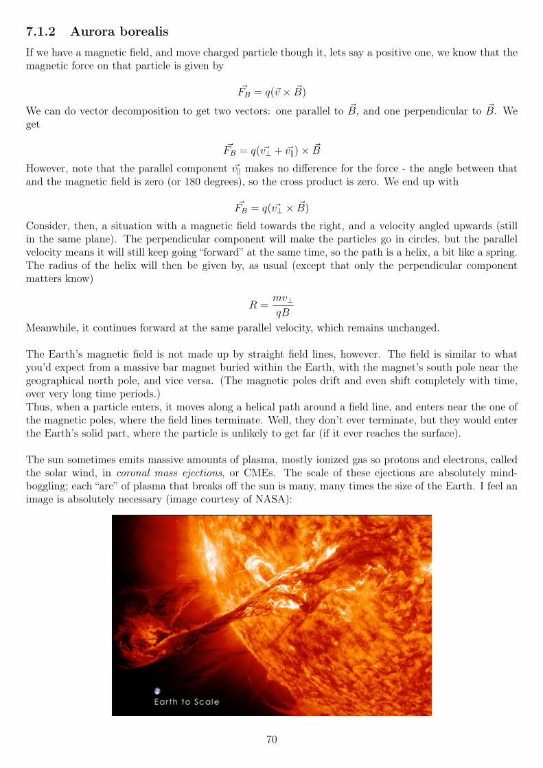
7.1.2 Aurora borealis
If we have a magnetic field, and move charged particle though it, lets say a positive one, we know that themagnetic force on that particle is given by
~FB = q(~v × ~B)
We can do vector decomposition to get two vectors: one parallel to ~B, and one perpendicular to ~B. Weget
~FB = q( ~v⊥ + ~v‖)× ~B
However, note that the parallel component ~v‖ makes no difference for the force - the angle between thatand the magnetic field is zero (or 180 degrees), so the cross product is zero. We end up with
~FB = q( ~v⊥ × ~B)
Consider, then, a situation with a magnetic field towards the right, and a velocity angled upwards (stillin the same plane). The perpendicular component will make the particles go in circles, but the parallelvelocity means it will still keep going “forward” at the same time, so the path is a helix, a bit like a spring.The radius of the helix will then be given by, as usual (except that only the perpendicular componentmatters know)
R =mv⊥qB
Meanwhile, it continues forward at the same parallel velocity, which remains unchanged.
The Earth’s magnetic field is not made up by straight field lines, however. The field is similar to whatyou’d expect from a massive bar magnet buried within the Earth, with the magnet’s south pole near thegeographical north pole, and vice versa. (The magnetic poles drift and even shift completely with time,over very long time periods.)Thus, when a particle enters, it moves along a helical path around a field line, and enters near the one ofthe magnetic poles, where the field lines terminate. Well, they don’t ever terminate, but they would enterthe Earth’s solid part, where the particle is unlikely to get far (if it ever reaches the surface).
The sun sometimes emits massive amounts of plasma, mostly ionized gas so protons and electrons, calledthe solar wind, in coronal mass ejections, or CMEs. The scale of these ejections are absolutely mind-boggling; each “arc” of plasma that breaks off the sun is many, many times the size of the Earth. I feel animage is absolutely necessary (image courtesy of NASA):
70
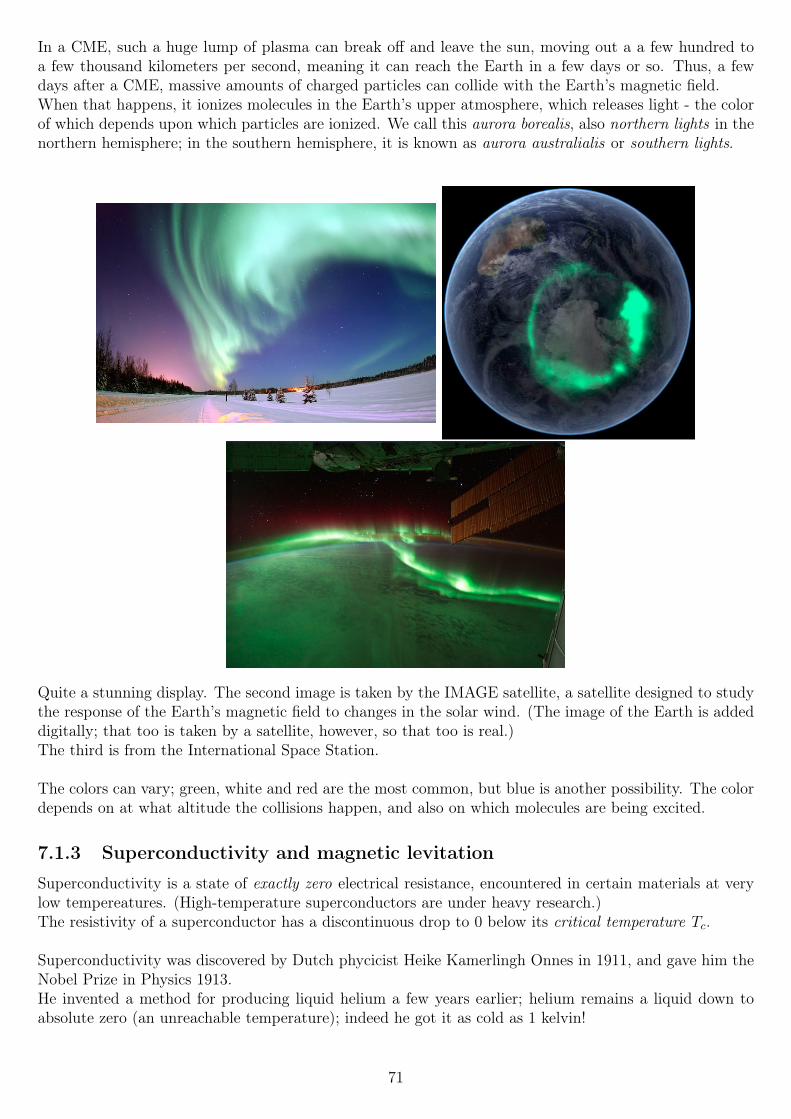
In a CME, such a huge lump of plasma can break off and leave the sun, moving out a a few hundred toa few thousand kilometers per second, meaning it can reach the Earth in a few days or so. Thus, a fewdays after a CME, massive amounts of charged particles can collide with the Earth’s magnetic field.When that happens, it ionizes molecules in the Earth’s upper atmosphere, which releases light - the colorof which depends upon which particles are ionized. We call this aurora borealis, also northern lights in thenorthern hemisphere; in the southern hemisphere, it is known as aurora australialis or southern lights.
Quite a stunning display. The second image is taken by the IMAGE satellite, a satellite designed to studythe response of the Earth’s magnetic field to changes in the solar wind. (The image of the Earth is addeddigitally; that too is taken by a satellite, however, so that too is real.)The third is from the International Space Station.
The colors can vary; green, white and red are the most common, but blue is another possibility. The colordepends on at what altitude the collisions happen, and also on which molecules are being excited.
7.1.3 Superconductivity and magnetic levitation
Superconductivity is a state of exactly zero electrical resistance, encountered in certain materials at verylow tempereatures. (High-temperature superconductors are under heavy research.)The resistivity of a superconductor has a discontinuous drop to 0 below its critical temperature Tc.
Superconductivity was discovered by Dutch phycicist Heike Kamerlingh Onnes in 1911, and gave him theNobel Prize in Physics 1913.He invented a method for producing liquid helium a few years earlier; helium remains a liquid down toabsolute zero (an unreachable temperature); indeed he got it as cold as 1 kelvin!
71
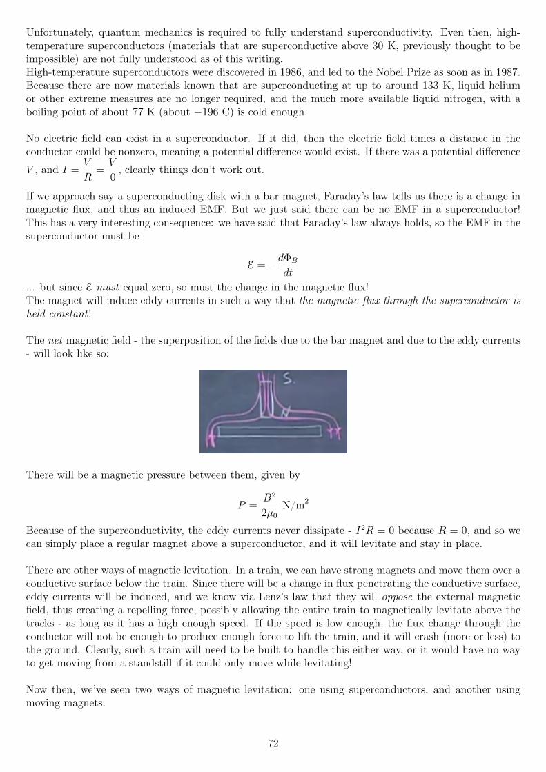
Unfortunately, quantum mechanics is required to fully understand superconductivity. Even then, high-temperature superconductors (materials that are superconductive above 30 K, previously thought to beimpossible) are not fully understood as of this writing.High-temperature superconductors were discovered in 1986, and led to the Nobel Prize as soon as in 1987.Because there are now materials known that are superconducting at up to around 133 K, liquid heliumor other extreme measures are no longer required, and the much more available liquid nitrogen, with aboiling point of about 77 K (about −196 C) is cold enough.
No electric field can exist in a superconductor. If it did, then the electric field times a distance in theconductor could be nonzero, meaning a potential difference would exist. If there was a potential difference
V , and I =V
R=V
0, clearly things don’t work out.
If we approach say a superconducting disk with a bar magnet, Faraday’s law tells us there is a change inmagnetic flux, and thus an induced EMF. But we just said there can be no EMF in a superconductor!This has a very interesting consequence: we have said that Faraday’s law always holds, so the EMF in thesuperconductor must be
E = −dΦB
dt
... but since E must equal zero, so must the change in the magnetic flux!The magnet will induce eddy currents in such a way that the magnetic flux through the superconductor isheld constant !
The net magnetic field - the superposition of the fields due to the bar magnet and due to the eddy currents- will look like so:
There will be a magnetic pressure between them, given by
P =B2
2µ0
N/m2
Because of the superconductivity, the eddy currents never dissipate - I2R = 0 because R = 0, and so wecan simply place a regular magnet above a superconductor, and it will levitate and stay in place.
There are other ways of magnetic levitation. In a train, we can have strong magnets and move them over aconductive surface below the train. Since there will be a change in flux penetrating the conductive surface,eddy currents will be induced, and we know via Lenz’s law that they will oppose the external magneticfield, thus creating a repelling force, possibly allowing the entire train to magnetically levitate above thetracks - as long as it has a high enough speed. If the speed is low enough, the flux change through theconductor will not be enough to produce enough force to lift the train, and it will crash (more or less) tothe ground. Clearly, such a train will need to be built to handle this either way, or it would have no wayto get moving from a standstill if it could only move while levitating!
Now then, we’ve seen two ways of magnetic levitation: one using superconductors, and another usingmoving magnets.
72
A third form requires neither speed nor superconductors, but instead uses alternating current in a loop.
Imagine a current loop, through which we pass an alternating current, above a conducting plate.At one moment in time, the magnetic field due to the coil will point downwards, i.e. have its north poletowards the conducting plate. Lenz’s law tells us the eddy currents will produce a magnetic field thatopposes this, and so the two plates will repel each other, and there will again be a magnetic pressurebetween the two.
However, slightly later in time, the magnetic field will now be decreasing, and so the eddy currents flipdirection, such that the current loop’s field still has its north pole downwards (but the flux through theplate is decreasing), but with the eddy current’s field flipped, the two will now attract each other.It therefore seems reasonable to conclude that they will repel and attract each other equally, on average;this is not the case, and there will be a net repelling force, the source of which is discussed in next week,when inductance is discussed.(A preview: there is a lag in the eddy current versus the induced EMF, such that they repel each othermore than 50% of the time, so the net force on the current loop is upwards.)
The magnetic levitation of a woman
We then reach the section responsible for the lecture’s name. Magicians used to (seemingly) levitate people- stereotypically, they were women - using various tricks. Can we do it using magnetic levitation?We have the equation for the magnetic pressure,
P =B2
2µ0
Using a current loop of area 0.1 m2, we find that using a B-field strength of about 0.15 tesla, the pressureis
P ≈ 9000N/m2
Multiplying that by the area, we get a force of roughly 900 newtons, enough to lift a hair over 90 kilogramsin the Earth’s gravitational field - so that should be enough to lift a person.However, generating such a strong B-field proves very difficult, as you need a very high current. Thus,the demo is about levitating a blow-up doll - which tells us that magicians most likely don’t use magneticlevitation in their tricks.
7.2 Inductance and RL circuitsSelf-inductance (as opposed to mutual inductance, discussed later in the course), often called inductancefor short, is a way to quantify the ability of a circuit to fight the change in magnetic flux produced by thecircuit itself.We know that if you run a current through a circuit, a magnetic field is created. If the current is changingwith time, then the magnetic fields are also changing with time, which causes an induced EMF in thecircuit, fighting the change.
The magnetic flux is always proportional to the current, ΦB ∝ I. The constant of proportionality is thenthe self-inductance, for which we use the symbol L:
ΦB = LI
If we combine this with Faraday’s law,
E = −dΦB
dt
73
We find that
E = −LdIdt
... assuming that L is constant, i.e. it is not a function of time. That is usually a pretty good assumption,as L is, just like capacitance C, only a function of the geometry. We will soon find many other similaritiesbetween capacitors and self-inductors.
Self-inductance of a solenoid
Say we run a current I through a solenoid, with N windings, each of which has radius r, and the lengthof the solenoid is `.
First, the B-field inside, given by a quick-and-dirty Ampere’s law calculation, is
Ba = µ0Ipen = µ0IaN
`
B =µ0NI
`
... where a is the length of the Gaussian rectangle we choose. (See the section on Ampere’s law for aproper derivation.)
If we attach an open surface to the current loop in the solenoid - difficult to visualize, but it will have anarea where the flux penetrates of Nπr2, with N again being the number of windings. The flux is thenthat area, times the B-field inside, so
ΦB = N2πr2µ0I
`
This is then equal to LI by definition, as we said earlier, so we can now calculate the self-inductance Lfor a solenoid:
LI = N2πr2µ0I
`
L =N2πr2µ0
`
As promised, it is only a function of the geometry, plus two other constants π and µ0.
The SI unit of inductance is the henry, H.
1H = 1V · sA
All circuits have a nonzero self-inductance, just as how they have a nonzero capacitance, and (for non-superconductors) a nonzero resistance.We can show this easily as follows: all current flows in loops. All loops, no matter their shape, produce amagnetic field, which produces a magnetic flux. Therefore all circuits have a nonzero self-inductance, nomatter how small it might be.
From here on, I will mostly refer to self-inductors simply as inductors. The only potential confusion is withmutual inductance, which will not be discussed at all in this chapter, only mentioned like now. Mutualinductance however requires multiple coils with physical proximity, which makes it irrelevant here.
74
7.2.1 Direct-current RL circuits
Say we have a very simple series circuit: a battery, a switch, a self-inductor, and a resistor.The switch is open to begin with, so the current at time t = 0, the current is zero.
The inductor will try to fight the change in current, and so the current will ramp up slowly. In the end,
the current in the circuit will be simply I =V
R, with R being the resistance of the resistor.
(We often calculate as if inductors have zero resistance; that is of course not true, since all wire will havesome resistance. However, whenever that resistance is necessary to care about, we can often model it asan ideal inductor in series with a resistor.)
So at t = 0, I = 0, and with t→∞, I =V
R. What about in between the two extremes? Well, let’s try to
set up an equation that describes the circuit.This is a critical point of this week, and perhaps of the entire course so far. Prof. Lewin states in nouncertain terms that the way most books do this is incorrect - the end result is correct, but the thoughtbehind the result is misleading and/or incorrect.Therefore I will list both the correct and the incorrect solutions here, and talk about the differences.This is explained in greater detail in the supplemental lecture notes for lecture 20, and is probably betterexplained there, by a physics professor, rather than by a student!
So, let’s see. The circuit has an inductor. That means there will be time-changing magnetic fields. Thatmeans that Kirchoff’s loop rule does not apply ! This is crucial. Instead, we will have to do a line integral~E · ~d` around the loop, and set it equal to −dΦB
dt, not set it equal to zero!
To clarify: Kirchhoff’s rule is a special case of Faraday’s law. It only holds when the change in flux is zero,because they state conflicting results for the same integral:∮
~E · ~d` = −dΦB
dt(Faraday’s law, always true!)∮
~E · ~d` = 0 (Kirchhoff’s rule, NOT always true!)
With Faraday’s law being the one that is always correct, clearly then Kirchhoff’s rule is correct ONLYwhen
−dΦB
dt= 0
With that in mind, let’s move on, and use Faraday’s law as necessary.
RL circuit analysis and a long note on Kirchoff’s second rule
We start to the right of the battery. We treat the switch as ideal, so it doesn’t contribute at all (we won’teven write a 0 for it in the equation, but treat it as if it doesn’t exist). After that, we reach the inductor.~E · ~d` is ZERO for the inductor, as we treat it as having no resistance (inductors are made to have as lowa resistance as possible). No resistance means no electric field, and so the dot product must be ZERO !So far, our integral is still at zero.After the inductor, we reach the resistor. The electric field inside the resistor is in the same direction asthe current, so the dot product of ~E · ~d` is positive, and equals IR; Ohm’s law works here. We then reachthe voltage source/battery. Here, the electric field is in the opposite direction of the current - the E-fieldalways goes from positive to negative, but the current inside a battery does not. Therefore the voltagesource contributes with a −V term.
75
Finally, the sum of all these terms must be equal not to zero, but via Faraday’s law, to the negative of the
rate of change of the flux, that is, −dΦB
dt. All in all, the equation is then
0 + IR− V = −dΦB
dt
We have said earlier that ΦB = LI, so if we substitute that in there, we get
0 + IR− V = − d
dt(LI)
0 + IR− V = −LdIdt
Thus, we have used Faraday’s law in the proper way: the left side of the line integral is the sum of thepotential differences over the circuit: the potential difference across the inductor is zero, because we treatit as having 0 resistance, and thus no E-field can exist in it.The right side is equal to the negative of the rate of charge of the magnetic flux, as always in Faraday’slaw. THIS is where the inductor’s term is: it is due to the flux, and is not really a “potential difference”per se, as electric potential is only applicable to conservative fields - and with changing magnetic flux, wehave non-conservative fields!
We therefore have a differential equation that we can solve, and thus find the value of the current in thecircuit. First, however, let’s take a look at the incorrect approach used by most physics books.
The approach taken by them is to modify Kirchhoff’s loop rule, such that the potential difference (or the
voltage drop, different name for the same thing) across all inductors is −LdIdt
, if we move in the assumeddirection of the current. Thus, when we do that, and move across the loop in the same direction, and setit all equal to zero via Kirchhoff’s here invalid rule. We now ignore the electric fields, and think in termsof potential: when we go up in potential, we add (so going through a voltage source from - to + meanswe add, otherwise subtract; going through a resistor where we enter from the + side means we subtract).
This means we add −LdIdt
for the inductor - remember, the minus sign is from this “rule” (see above), weare adding the term. We then subtract IR for the resistor, and finally add V for the voltage source. Thisis then set equal to 0:
−LdIdt− IR + V = 0
Note that this equation is identical to the one we found before, only that it has been rearranged. If we
take our “proper” equation and move IR and V to the same side as −LdIdt
, we get the above. Thus,mathematically, both ways yield the correct answer.
So, if they give the same result, what’s all the fuss about? The problem is in what the equations represent.In the correct equation that we found, we follow Faraday’s law: the integral of the electric field aroundthe loop - ~E · ~d` - all added up, equals the negative of the rate of change of the magnetic flux.While the right-hand side also has the SI unit of volts, it is not a true potential difference, as the conceptof potential does not apply to non-conservative fields.
The “incorrect” equation, on the other hand, is really implying that the sum of the potential differencesaround the loop (
∮~E · ~d`) is zero, which it is not ! The sum of the potential differences,
∮~E · ~d`, is equal
to −dΦB
dtand nothing else! Faraday’s law!
The “incorrect” equation therefore also implies that the potential difference across the inductor is −LdIdt,
which IS what you would measure with a voltmeter, but IS NOT correct. In the ideal inductor, the E-fieldis ZERO, so ~E · ~d` for the inductor is also zero!
76
The reason a voltmeter would measure the same value is not because there is a true potential difference,but that when you connect a voltmeter, you get a RL-circuit with the voltmeter’s internal resistanceproviding (most of) the resistance. Therefore, we must apply Faraday’s law to that circuit as well, and wefind the same result (−LdI
dt); however the physical cause is again a change in magnetic flux via Faraday’s
law, and not a true potential difference across the inductor!Thus, the result (the number displayed by the voltmeter) is the same, but the physical reasons are vastlydifferent !If this is still confusing to you (especially everything prior to the voltmeter part, which seems even moreconfusing), read (or re-read) the lecture supplement, and perhaps especially the last sentence:“If you find all this confusing, you are in good company. This is one of the most difficult and subtle topicsin this course — it trips up experts all the time. Not easy!”
RL circuit analysis continued
So, getting back to where we were. We want to solve the differential equation
IR− V = −LdIdt
which governs this circuit. We add the additional constraint (boundary condition) that I(0) = 0, thatis, the current at t = 0 is 0. Without this condition, we cannot get a unique solution to the differentialequation.Solving it, we get
I(t) =V
R
(1− e−
RtL
)Alternatively, a bit easier to read, using ex = exp(x):
I(t) =V
R
(1− exp (−Rt
L)
)If we take the limit as t→ 0, we find that the current is indeed zero.
Also, in the limit as t→∞ the current isI
R, as we expected.
In between the two, the current increases exponentially, asymptotically approaching the maximum current.During this time, the inductor sucks up energy, and stores it in the magnetic field it creates. This energy islater freed again when the field collapses, whenever the inductor fights a current change by itself providinga current.
After one time constant, τ =L
R(the unit of henry divided by ohm is indeed seconds!), the current has
increased to 1− e−1 ≈ 63.2% of its maximum value. After two time constants, the current is ≈ 86.47% ofits maximum.
If we reverse our thinking: at what time is the current x times its maximum value, for 0 < x < 1?
The “current multiplier”, so to speak, is then both x and 1− exp(−RLt), so we can set the two equal and
solve for t:
1− exp(−RLt) = x
− exp(−RLt) = x− 1
exp(−RLt) = 1− x
77
−RLt = ln (1− x)
t = −LR
ln (1− x)
We now know how the circuit behaves as the power is connected. What happens when it is disconnected?That is, we remove the voltage source and replace it by a short circuit (not an open circuit!).Since the inductance will fight the change, we expect the current to go down gradually. It has to stopeventually; power is “burned” in the resistor, so without a power source, a current cannot run forever.Until then, the magnetic field in the inductor collapses, and the magnetic energy will power the resistor.
To find the quantitative answer, we need to solve the same differential equation as before, but with V = 0.We will find the answer to be
I(t) =V
Rexp(−Rt
L)
with V being the now-removed battery’s voltage, so that VRwas the stable current prior to the change we
just did to the voltage source.So if we redefine t = 0 to be a time where the current in V
R, we find that indeed, the equation holds; the
current is its maximum. Same goes for t→∞, where the current will asymtotically approach zero, in thesame way it asymtotically reached its maximum before.After one time constant τ = L
R, then, we find the current to be about 36.8% of its maximum value; after
two time constants 13.6%, and so on.
A common rule of thumb in electrical engineering is to take the process as complete after 5 time constants.Thus, for an increasing current, after 5 time constants, it will be at ≈ 99.33% of its maximum, while for adecreasing current, it will be down to ≈ 0.67%, which we consider essentially 100% and 0%, respectively.
We know that the power dissipated in the resistor is I2R at all times, so we can use that fact, and the factthat the circuit now only contains an ideal inductor, ideal resistor and ideal wires, to calculate the totalenergy stored. We do that do integrating the power dissipated in the resistor over all time from t = 0,when I = Imax, to t→∞, when the current has died out:
E =
∫ ∞0
I2R dt =
(Imax exp(−R
Lt)
)2
R = I2max R
∫ ∞0
exp(−2R
Lt)dt
Note the added two inside the exponential, since we raised it to the 2nd power. The result of the integralis ∫ ∞
0
exp(−2R
Lt)dt =
L
2R
So the power is
I2maxR
L
2R= I2
max
L
2=
1
2LI2
max
This relation holds for the current through the inductor at any instant in time, so we can remove the“max”, and get an equation relating the current to the stored energy at any time:
E =1
2LI2
78
Dual circuit elements
Notice the striking similarity between this, and the energy stored in a capacitor:
E =1
2CV 2
This is another of many similarities between the capacitor and the inductor, which are dual circuit elements.Capacitors store energy in electric fields; inductors store energy in magnetic fields.Capacitors fight a change in the voltage across them; inductors fight a change in the current through them.The current through a capacitor is related to the rate of charge of the voltage across it:
I(t) = CdV
dt
The voltage across an inductor is related to the rate of change on the current through it:
V (t) = LdI
dt
If we integrate both sides of these equations, we will also find that the voltage across a capacitor is relatedto the integral of the current, and that the current through an inductor is related to the integral of thevoltage across it. This had the rather profound implication that to calculate the current through aninductor, we must know its entire history, so to speak - we must know the voltage across it from t = −∞up to the time where we want to know the current. Either that, or just the voltage across it from t1 to t2,plus i(t1).The same, or perhaps rather the opposite, is true for capacitors.This makes capacitors and inductors state devices, that essentially have a memory, of a sort.
Magnetic field energy density
Going back to the magnetic field energy, since we know that stored energy, and we know the volume ofthe solenoid, andt he fact that the magnetic field is essentially exclusively enclosed with it (the B-fieldoutside due to the solenoid is roughly zero), we can calculate the solenoid’s magnetic field energy density,by dividing the stored energy by the solenoid’s volume.First, we can substitute in values for L and I that we had found previously, into the equation. Namely,these values:
B = µ0IN
`
we solve that for I, and find
I =B`
µ0N
We also had a value for L:
L = πr2N2
`µ0
Substituting them into the equation, we have
1
2LI2 =
1
2
(πr2N
2
`µ0
)(B`
µ0N
)2
=1
2
(πr2N
2
`µ0
)(B2`2
µ20N
2
)1
2πr2µ0
B2`2
`µ20
1
2πr2B
2`
µ0
79
Note however, that because we’ve assumed that the magnetic field outside the solenoid is zero, and thatπr2` is the volume where the field exists, we can divide out those terms, and find the magnetic field energydensity:
U =B2
2µ0
J/m3
This, too has an electrical analogue. We calculated the electric field energy density for a capacitor, whichwe found te be
ε0κE2
2J/m3
In the electrical case, this represents the work required to assemble charges in a certain configuration.In the case of the inductor, this represents the work required to get the current running through a pureself-inductor (one with zero electrical resistance). It takes work because the inductor fights the change.
7.2.2 Alternating-current RL circuits
What if we have an RL circuit and power it by an alternating current? Say we have as simple series circuitwith a voltage source of voltage V0 cosωt, a self-inductor L and a resistor R.Say the current is clockwise at one moment in time.We walk around the circuit and add up the potential differences
∮~E · d`, according to Faraday’s law, and
then set those equal to the negative of the magnetic flux change.First, we reach the inductor. As before, the E-field is ZERO inside the ideal inductor, so it doesn’t con-tribute at all to the potential difference sum.We then reach the resistor, where the E-field is in the same direction as the current, an so we add apotential difference of IR.Finally, we reach the voltage source.The E-field is a power source is always in the opposite direction of the current, so it contributes with a−V0 cosωt term.
Finally, on the right-hand side, we have the change in flux −dΦB
dt= −LdI
dt, via Faraday’s law, and the
equivalence via the definition of inductance, LI = ΦB.All in all, we have
0 + IR− V0 cosωt = −LdIdt
And again, we solve this differential equation. Unfortunately, the solution to this equation is a bit complex- and this result is the simplified version; the unsimplified answer is quite a bit worse!We find that
I(t) =V0√
R2 + (ωL)2cos(ωt− φ)
where
tanφ =ωL
R
We can note two imporant facts here. First, the current will be sinusoidal (as we would expect), with apeak of
Ipeak =V0√
R2 + (ωL)2
... which is just the term that multiplies the cosine; this comes simply from the fact that the cosine justmoves between −1 and +1.
80
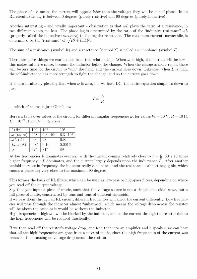
The phase of −φ means the current will appear later than the voltage; they will be out of phase. In anRL circuit, this lag is between 0 degrees (purely resistive) and 90 degrees (purely inductive).
Another interesting - and vitally important - observation is that ωL plays the term of a resistance, intwo different places, no less. The phase lag is determined by the ratio of the “inductive resistance” ωL(properly called the inductive reactance) to the regular resistance. The maximum current, meanwhile, isdetermined by the “resistance” of
√R2 + (ωL)2.
The sum of a resistance (symbol R) and a reactance (symbol X) is called an impedance (symbol Z).
There are more things we can deduce from this relationship. When ω is high, the current will be low -this makes intuitive sense, because the inductor fights the change. When the charge is more rapid, therewill be less time for the circuit to “win” the fight, and the current goes down. Likewise, when L is high,the self-inductance has more strength to fight the change, and so the current goes down.
It is also intuitively pleasing that when ω is zero, i.e. we have DC, the entire equation simplifies down tojust
I =V0
R
... which of course is just Ohm’s law.
Here’s a table over values of the circuit, for different angular frequencies ω, for values V0 = 10 V, R = 10 Ω,L = 10−2 H and V = V0 cosωt:
f (Hz) 100 103 104
ω (rad/s) 628 6.3 · 103 6.3 · 104
ωL (Ω) 6.3 63 628Imax (A) 0.85 0.16 0.0016φ 32 81 89
At low frequencies R dominates over ωL, with the current coming relatively close to I = VR. At a 10 times
higher frequency, ωL dominates, and the current largely depends upon the inductance L. After anothertenfold increase in frequency, the inductor really dominates, and the resistance is almost negligible, whichcauses a phase lag very close to the maximum 90 degrees.
This formes the basis of RL filters, which can be used as low-pass or high-pass filters, depending on whereyou read off the output voltage.Say that you input a piece of music, such that the voltage source is not a simple sinusoidal wave, but afull piece of music, constructed by tons and tons of different sinusoids.If we pass them through an RL circuit, different frequencies will affect the current differently. Low frequen-cies will pass through the inductor almost “unharmed”, which means the voltage drop across the resistorwill be about the same as it would be without the inductor.High frequencies - high ω - will be blocked by the inductor, and so the current through the resistor due tothe high frequencies will be reduced drastically.
If we then read off the resistor’s voltage drop, and feed that into an amplifier and a speaker, we can hearthat all the high frequencies are gone from a piece of music, since the high frequencies of the current wasremoved, thus causing no voltage drop across the resistor.
81
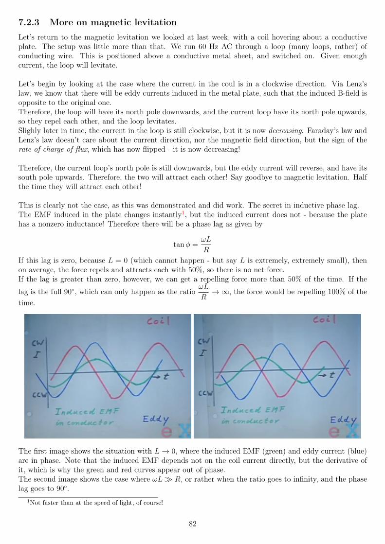
7.2.3 More on magnetic levitation
Let’s return to the magnetic levitation we looked at last week, with a coil hovering about a conductiveplate. The setup was little more than that. We run 60 Hz AC through a loop (many loops, rather) ofconducting wire. This is positioned above a conductive metal sheet, and switched on. Given enoughcurrent, the loop will levitate.
Let’s begin by looking at the case where the current in the coul is in a clockwise direction. Via Lenz’slaw, we know that there will be eddy currents induced in the metal plate, such that the induced B-field isopposite to the original one.Therefore, the loop will have its north pole downwards, and the current loop have its north pole upwards,so they repel each other, and the loop levitates.Slighly later in time, the current in the loop is still clockwise, but it is now decreasing. Faraday’s law andLenz’s law doesn’t care about the current direction, nor the magnetic field direction, but the sign of therate of charge of flux, which has now flipped - it is now decreasing!
Therefore, the current loop’s north pole is still downwards, but the eddy current will reverse, and have itssouth pole upwards. Therefore, the two will attract each other! Say goodbye to magnetic levitation. Halfthe time they will attract each other!
This is clearly not the case, as this was demonstrated and did work. The secret in inductive phase lag.The EMF induced in the plate changes instantly1, but the induced current does not - because the platehas a nonzero inductance! Therefore there will be a phase lag as given by
tanφ =ωL
R
If this lag is zero, because L = 0 (which cannot happen - but say L is extremely, extremely small), thenon average, the force repels and attracts each with 50%, so there is no net force.If the lag is greater than zero, however, we can get a repelling force more than 50% of the time. If the
lag is the full 90, which can only happen as the ratioωL
R→∞, the force would be repelling 100% of the
time.
The first image shows the situation with L→ 0, where the induced EMF (green) and eddy current (blue)are in phase. Note that the induced EMF depends not on the coil current directly, but the derivative ofit, which is why the green and red curves appear out of phase.The second image shows the case where ωL R, or rather when the ratio goes to infinity, and the phaselag goes to 90.
1Not faster than at the speed of light, of course!
82
The reality would be somewhere in between. Any phase lag greater than 0 degrees give a net repellingforce, thus allowing levitation; a greater lag would mean a greater net repelling force.
Of course, if the conductor is in fact a superconductor, then the phase lag will be exactly 90 degrees, andthe force will always be repelling.
7.3 Magnetic materials
7.3.1 A short note on motors
The lecture begins with some information about the MIT motor contest, which was held when the lectureswere recorded. Not a lot of physics is discussed, except one point about motors and current.The ohmic resistance of a motor’s windings is often very low, so a very high current will flow when themotor is just starting up. As it starts spinning, there is an induced EMF according to Faraday’s law,which will counteract the external supply. Thus the current drops drastically, and later on settles at avalue, when the rotational speed is constant.
Therefore, if we hold a motor still while it is powered, the high current may damage it, so one should takecare to avoid this.
7.3.2 Magnetic dipole moment
As we have seen with some motor designs, a current loop in a magnetic field will experience a torque.Imagine a rectangular current loop, with sides a and b, with a current that is counterclockwise as seenfrom above. Say the left and right sides are a, and the other two b.Say there is a uniform magnetic field B towards the rightThe magnetic force on a straight wire will be ~I × ~B (or I~L× ~B, since I is not really a vector).For the right a side, the force will be experience a force in the downwards direction; the left a side willexperience a force upwards. The b sides will experience no force, as the cross product is zero there - theyare parallel and antiparallel with the magnetic field, respectively.
Thus, there will be a net torque on the loop, given by |~τ | = IabB. If we define A = ab to be the area ofthe loop, we get |~τ | = IAB.If there is an angle between the loop and the B-field, the magnitude is given by |~τ | = IAB sin θ. Thus, wecan write the torque as a cross product:
~τ = I ~A× ~B
where the vector area ~A has the magnitude of the loop’s area, and the direction of the upwards surfacenormal perpendicular to it.
The magnetic dipole moment ~µ is defined as this product I ~A:
~µ = I ~A
~µ then has the unit of ampere-square meters, A ·m2, or equivalently joule per tesla (J/T).So the torque can also be written as
~τ = ~µ× ~B
Because of its definition, the vector ~µ always points from the dipole’s south to its north pole, which makesit a handy tool in several places. It is sometimes known as ~m rather than ~µ.
83
7.3.3 The source of magnetism in matter
First off, let’s state one thing clearly: what will follow here is mostly a classical interpretation of mag-netism. For the truly correct answers, quantum physics is required. However, the results we find here areoften in fairly good agreement with the correct ones.
We know that current loops create a magnetic field. For a simple circular loop, going counterclockwise asseen from above, the field (and thus the magnetic dipole moment ~µ is upwards, via the right-hand rule.This is the source of all magnetic fields, including those inside permanent magnets!
We also know that induced eddy currents create magnetic fields, but how does that apply to permanentmagnets, which do not rely on a change in external magnetic fields, or indeed do not rely on any externalmagnetic fields?The answer is that it doesn’t apply: the mechanism is different.
Up until this moment in the course, I struggled to understand how a permanent magnet could possiblywork, given what we’d learned prior... And then I read something similar to what follows in the nextparagraph, and it just clicked. There are simple current loops in all materials!
In the classical model of the atom, we have electrons in circular orbits, orbiting around the much moremassive nucleus. Because the definition of a current is a charge moving over time, the electron orbitsconstitute tiny current loops - they are moving in a circle!We can define the magnetic dipole moment of an electron orbital by first finding its current in amperes,and then using the definion for µ = IA.The current is the charge, divided by its period T . The period is in turn given by the distance travelled(the circle’s circumference), divided by the velocity v:
T =2πr
vThe electron’s charge is −e, so we divide that charge by T , looking only at the magnitudes for now:
|I| = | − e|v2πr
(The current is defined by the amount of charge passing by a point, per second. Dividing the charge bythe period will get us that number!)The magnetic dipole moment is then the current times the loop area A = πr2:
µ =ev
2πrπr2 =
evr
2Because the electron has a negative charge, the current is then in the opposite direction of its orbit. If theelectron orbits clockwise as seen from above, we define the current I as being counterclockwise.The magnetic field created follows the right-hand rule of the current’s direction, so the magnetic dipolemoment is then pointing upwards, according to the right-hand rule.
So if all electron orbits produce a magnetic moment, and all materials contain orbiting electrons, why arenot all materials magnetic? The answer is simple: the magnetic moment due to one electron orbiting isusually cancelled by one orbiting in the opposite direction, so that the net force in a material with many,many electrons will be essentially zero.
We know that electric fields can induce electric dipoles in materials. In case the molecules or atoms them-selves are permanent electric dipoles, an external electric field will attempt to align them. The degree ofsuccess depends on how strong the external electric field is, and on the temperature: a lower temperaturemeans less random thermal motion, and so the dipoles are easier to align.
84
There is a similar situation with magnetic fields. If we have an external magnetic field, it can induce mag-netic dipoles in a material, at the atomic scale. In case the molecules/atoms themselves have a permanentmagnetic dipole moment, then the external magnetic field will attempt to align them. Again, the lowertemperature will lead to a greater degree of success, due to less thermal motion.
When we bring a material into an external field, then, the field inside the material from the external field.The external field will often be referred to as the vacuum field here.
When we dealt with dielectrics, we saw how an electric field could change inside a nonconductive material;the effect was that the electric field inside was lowered by a factor κ, the dielectric constant of the material.Since κ > 1 for all natural materials, at least (and κ = 1 for the vacuum), the electric field inside thematerial was always lower than the external electric field that induced the change to begin with.
That is in stark contrast to what we will now explore with magnetism. There are three possibilites, ratherthan the one for electric fields above, when we deal with magnetic fields. The magnetic field inside amaterial can be1) slightly lower than the external field (diamagnetic materials),2) slightly higher than the external field (paramagnetic materials), or3) a lot higher than the external field (ferromagnetic materials).
Ferromagnetism is the form that most people are familiar with, where e.g. iron is strongly attracted tomagnets.The other two forms have effects that are much weaker, to the point that they often go unnoticed. Forexample, water is diamagnetic, and thus repelled by magnetic fields - only that it is repelled very weakly.
Before we talk about the three forms of magnetism, we should introduce magnetization.
7.3.4 Magnetization
Now that we know where the permanent dipoles in matter come from, let’s look at a larger scale than theatomic one, where the electron orbits are, and switch our focus to what happens when we have lots andlots of these tiny dipoles in a material.
Suppose we have a cylindrical piece of material, with end-cap area A and height L, consisting of N individ-ual dipoles, each with a magnetic dipole moment ~µ, spread uniformly throughout the cylinder’s volume.All of the dipole moments are also aligned with the cylinder’s axis, i.e. they all point “upwards”.In the absence of an external magnetic field, what is the field due to these dipoles alone?
We define the magnetization vector ~M to be the net magnetic dipole moment per unit volume:
~M =1
V
∑i
~µ
In the case of the cylinder, since all moments are aligned, the net moment is simply Nµ. To get the “perunit volume” part, we just divide by the volume, AL:
M =Nµ
AL
Clearly, the direction of ~M is the same as all the individual moments ~µ, if they are all aligned.Since ~µ is in ampere-square meters (A ·m2), and the volume in cubic meters, the magnetization is then inamperes per meter, A/m.
The average magnetic field due to this magnetization BM is then given by
85
~BM = µ0~M
This is the large-scale average throughout the material; close to each of the dipoles, the field will be verydifferent.This principle is similar to the E-field due to several nearby point charges; in the vicinity of the changes,the field will be very complex, but from very far away, the field will look as one due to a single pointcharge, with the same charge as the sum of the charges due to the collection.
7.3.5 Paramagnetism
Let’s now start looking at the different forms of magnetism.In paramagnetism, the atoms or molecules in the material themselves have a magnetic dipole moment,such that they are in a way tiny magnets.In the absence of an external field, these dipoles are randomly oriented, such that there is no net magneticfield.Once exposed to an external field (a vacuum field), that field will attempt to align them. The successdepends on the vacuum field’s strength, and on the temperature, such that a lower temperature meanseasier alignment, due to reduced thermal motion.
The alignment will be such that the induced magnetic field in the material adds to the external field, andthe field inside the material is slighly stronger than the external field. This is in contrast to diamagnetism,where the field inside was weaker.Because of this, paramagnetic materials are attracted to magnetic fields, while diamagnetic materials arerepelled.
More quantitatively, the alignment of the atomic-scale dipoles with the external field (which we’ll call ~B0)creates a net magnetization ~M that is parallel to ~B0. Since the induced field ~BM is parallel to ~M , then~BM too is parallel to ~B0. We see, then, that the field due to the paramagnetism indeed strengthens theexternal field.The total magnetic field in the material is then given by
~B = ~B0 + ~BM = ~B0 + µ0~M
In most paramagnetic materials, ~M is proportional to the external field ~B0. The proportionality constantis known as the relative permeability, and is written as κm:
~B = κm ~B0
Because the effect of paramagnetism (and diamagnetism) is so small, κm is usually very close to 1, and soit gets cumbersome to talk about numbers such as the relative permeability of e.g. magnesium, which is≈ 1.000012. Because of this, we can also define the relation in terms of the magnetic susceptibility χm (χbeing the Greek letter chi) of a material. The relation between the two is such that
κm = 1 + χm
Thus, instead of the relative permeability of magnesium being 1.000012, we can talk about its magneticsusceptibility of 1.2 · 10−5.Both relative permeability and magnetic susceptibility are dimensionless numbers.
We can then combine the relative permeability with the permeability of free space µ0 to get the magneticpermeability µm (sometimes only µ, which can easily be confused with magnetic moment) of a material:
µm = κmµ0 = (1 + χm)µ0
86
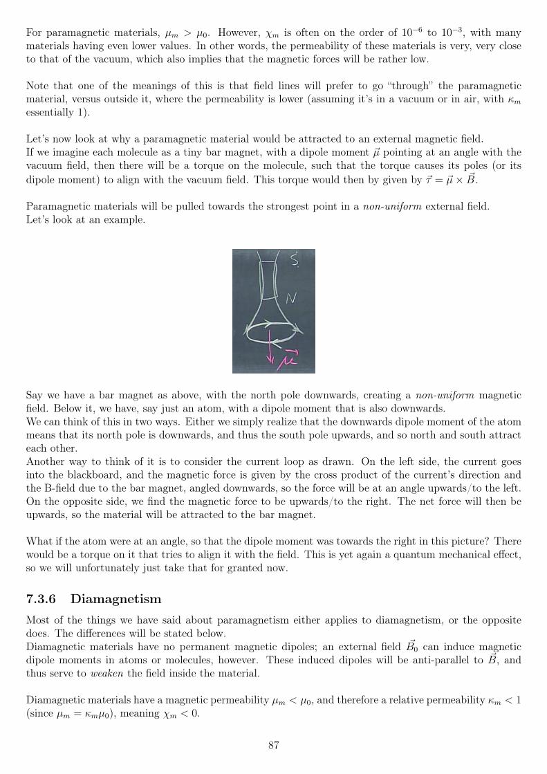
For paramagnetic materials, µm > µ0. However, χm is often on the order of 10−6 to 10−3, with manymaterials having even lower values. In other words, the permeability of these materials is very, very closeto that of the vacuum, which also implies that the magnetic forces will be rather low.
Note that one of the meanings of this is that field lines will prefer to go “through” the paramagneticmaterial, versus outside it, where the permeability is lower (assuming it’s in a vacuum or in air, with κmessentially 1).
Let’s now look at why a paramagnetic material would be attracted to an external magnetic field.If we imagine each molecule as a tiny bar magnet, with a dipole moment ~µ pointing at an angle with thevacuum field, then there will be a torque on the molecule, such that the torque causes its poles (or itsdipole moment) to align with the vacuum field. This torque would then by given by ~τ = ~µ× ~B.
Paramagnetic materials will be pulled towards the strongest point in a non-uniform external field.Let’s look at an example.
Say we have a bar magnet as above, with the north pole downwards, creating a non-uniform magneticfield. Below it, we have, say just an atom, with a dipole moment that is also downwards.We can think of this in two ways. Either we simply realize that the downwards dipole moment of the atommeans that its north pole is downwards, and thus the south pole upwards, and so north and south attracteach other.Another way to think of it is to consider the current loop as drawn. On the left side, the current goesinto the blackboard, and the magnetic force is given by the cross product of the current’s direction andthe B-field due to the bar magnet, angled downwards, so the force will be at an angle upwards/to the left.On the opposite side, we find the magnetic force to be upwards/to the right. The net force will then beupwards, so the material will be attracted to the bar magnet.
What if the atom were at an angle, so that the dipole moment was towards the right in this picture? Therewould be a torque on it that tries to align it with the field. This is yet again a quantum mechanical effect,so we will unfortunately just take that for granted now.
7.3.6 Diamagnetism
Most of the things we have said about paramagnetism either applies to diamagnetism, or the oppositedoes. The differences will be stated below.Diamagnetic materials have no permanent magnetic dipoles; an external field ~B0 can induce magneticdipole moments in atoms or molecules, however. These induced dipoles will be anti-parallel to ~B, andthus serve to weaken the field inside the material.
Diamagnetic materials have a magnetic permeability µm < µ0, and therefore a relative permeability κm < 1(since µm = κmµ0), meaning χm < 0.
87
Here, the magnitude of χm is even smaller than that of paramagnetic material, perhaps on the order of−10−5 to −10−9.
Just as how field lines prefer to go through paramagnetic materials, because of their (slightly) higher mag-netic permeability than the surrounding vacuum/air, field lines prefer to avoid/go around diamagneticmaterials, as the permeability is lower than that of the vacuum.This effect is striking in superconductors, which are essentially perfect diamagnets, with χm = −1 andµm = 0, such that they repel all fields entirely, except for a very thin layer near the surface (which isusually less than 1 micrometer deep, given by the London penetration depth, which is likely not coveredby this course).
All materials are diamagnetic; however, for those that are also paramagnetic or ferromagnetic, as we cansee on the tiny susceptibility of diamagnetic materials, those other effects will usually overshadow thediamagnetism.
As stated above, the induced dipoles weaken the internal magnetic field, and so they oppose the externalfield. Diamagnetic materials will therefore be repelled by external magnetic fields, as their dipole momentwill always tend to oppose external fields.
Due to the low susceptibility, the effects of diamagnetism is usually very small, and often hard to evennotice, at least in everyday life. It does however result in water, a diamagnetic material, being repelled byvery strong magnetic fields, to the point that phycisists have levitated a living frog (and also mice) by therepelling force on the water inside it. Doing so took a magnetic field with a strength of roughly 16 tesla!
7.3.7 Ferromagnetism
Ferromagnetism is perhaps the most interesting form of magnetism, because it forms the basis of perma-nent magnets.
Like paramagnetic materials, ferromagnetic materials also have permanent dipole moments.However, (yet again!) for quantum mechanical reasons beyond this course, these dipoles are grouped intodomains, which are on the order of 10−6 to 10−4 m in size (very roughly), such that even large domains areessentially microscopic. Inside each of these domains, all the individual dipole moments will be completelyaligned in one and the same direction. However, since there are many domains in a piece of material, theremay still not be a net magnetic moment. Each domain has a separate alignment, which may cancel outwith another nearby domain, to provide no net moment.There may be up to on the order of 1017 to 1021 atoms in a single domain.
As we’ve seen before, when we expose the material to an external magnetic field, the dipoles (and thus thedomains) will try to align along the external magnetic field; the degree of success depends on the strengthof the external magnetic field, and on the temperature; the lower the temperature, the easier alignmentis, due to lower thermal motion.The magnetic field inside a ferromagnetic material may be thousands of times stronger than that of theexternal field, that is, κm can be 1000 or more. That’s in fairly stark contrast to paramagnetic and dia-magnetic materials, which had factors more on the order of 1.001 or less!
In addition, the domains in a ferromagnetic materials can stay aligned, to a certain degree, after the re-moval of the external field, creating permanent magnets.This alignment can be removed either by sudden shock (such as hitting the material with a hammer), orby heating the material; in either case, the domains will randomize again and the residual magnetism maywell go away entirely.
88
When we heat a ferromagnetic materials, at a certain temperature, the domain completely fall apart, anddisappear. The point where this happens is nown as the Curie temperature, or the Curie point. Iron’sCurie temperature is 1043 degrees K, or 770 degrees Celsius.At this point, the material becomes paramagnetic instead, in a very abrupt change.
89
Chapter 8
Week 8
8.1 Hysteresis and electromagnetsLast week, we talked about magnetic permeability, the relative permeability κM of materials, and brieflyabout ferromagnetism, the only form of magnetism where κM has a significant value. We will now talkabout how strong a magnetic field we can theoretically get in a material, and about hysterisis in ferromag-netism - a phenomenon where the past state of the material changes its permeability, in a nonlinear fashion(so the magnetization and permeability are no longer directly proportional to the external magnetic field).
If we were to align 100% of the atomic dipoles in a material, what would the strength of that field be?Let’s start with a slightly different derivation, that we will later use to answer the above question.
Say we have a hydrogen atom, consisting of a proton at the center, and an electron orbiting with a radiusR, in the classical model.If the electron, as seen from above, orbits in a clockwise fashion, the current - we have a moving charge,so there is a current - will by convention be in the counterclockwise direction.The magnetic dipole moment ~µ is then given by IA, where A = πR2 is the area of the current loop. Thedirection will be, via the right-hand rule, upwards.Let’s then try to find the value for I, which takes a bit more work.
If the electron is orbiting in a circle around a center point, there must, according to classical mechanics,be a centripetal force on it, acting radially inwards. We can use Coulomb’s law to find the electric force,and set that equal to the centripetal force mv2
R:
mev2
R=|e|| − e|4πε0R2
v2 =e2
4πε0Rme
v =e
2√πε0Rme
The time to go one loop around (the period T ) is then the distance around, 2πR, divided by the velocity:
T =4πR√πε0Rme
e
If we stick some numbers in there, using R = 5·10−11 for the orbit radius (the Bohr radius, about 5.29·10−11
meters), we find v ≈ 2.3 · 106 m/s and T = 1.4 · 10−16 s - rather incredible numbers!
90
We can now calculate the current: current is defined as the amount of charge passing a point per second
- so if we choose a point along the orbit, the electron will pass it1
1.4 · 10−16times per second. We can
therefore calculate
I =e
T=
1.602 · 10−19
1.4 · 10−16≈ 1.144 · 10−3 A
We find a current of about a milliampere - due to a SINGLE electron orbiting! In a copper wire, a currentof a milliampere would take roughly 6.24 · 1015 electrons passing by a point per second (a coulomb isapproximately 6.24 · 1018 electrons, the reciprocal of the elementary charge 1.602 · 10−19 C) and in thiscase ONE electron is doing all that, because of its incredible velocity around the tiny orbit.
The magnetic moment is then µ = IA, as we stated, so
µ = IA = IπR2 ≈ 8.98 · 10−24 A m2
This value is known as the Bohr magneton. However, its value isn’t really what we just found, but ratherthe value of the Bohr magneton µB is
µB =e~
2me
≈ 9.274 · 10−24 J/T
... which is a result from quantum mechanics, which is where ~ comes from (the reduced Planck constant).The value cannot be found accurately using classical physics.The magnetic moment due to all electrons in orbit around an atom can only ever be a multiple of theBohr magneton - never anything it between. This is one example of the quantization (only a certain setof discrete values are allowed) that gives quantum physics its name.In another quantum weirdness effect, electrons themselves produce a magnetic moment due to a quantumeffect called spin, often thought classically as a literal spin of the electron, around its own axis.
The net magnetic dipole moment of an atom is then the vectorial sum of all the orbital dipole moments,due to the electrons’ orbits, and of the spin dipole moments. The result of that is that most atoms andmolecules have dipole moments of either one or two Bohr magnetons. The limit on the maximum fieldstrength in a material (due to the material itself), then, will be on the order of 2 Bohr magnetons, timesthe number of atoms we can manage to align all in the same direction.
When we expose a material to an external magnetic field, the field inside will be
~B = ~B0 + ~B′
where ~B0 is the external field (the vacuum field), and ~B′ is the field due to the aligned dipoles.For paramagnetic and diamagnetic materials, we then find that ~B = κM ~B0 = ~B0 +χM ~B0. However, as wewill soon see, that relationship does not hold so easily for ferromagnetic materials. The reason is that inferromagnetic materials, an external field can align dipoles so well that essentially all of them are aligned.At that point, clearly, increasing the external field will have no effect on the material’s dipole alignment -they are already aligned, and so ~B′ is at a maximum.When all dipoles are aligned, and an external field cannot increase the material’s induced field further, wecall that saturation.
Say we have a material where each atom contributes with 2 Bohr magnetons, with a “density” of N = 1029
atoms per cubic meter in our material.Inside the material, a solid material, the atoms will be nicely packed together. We can imagine them as alot of small current loops in a grid; each column of the grid (which is really 3-dimensional, of course) thenlooks a lot like a solenoid - many small windings, each with a current through them. Since we’ve said thatall dipole moments will be aligned, we can indeed approximate the B-field strength using the equation for
91
a solenoid’s magnetic field.
Each column will have an area A and a height `; let’s ` = 1 meter, for simplicity. Each column is thenA` = A m3 in volume. The equation for the B-field inside a solenoid is
B = µ0IN
`
So somehow, we need to find a way to put µB inside there. Note that N in the above equation is thenumber of windings, while N is a different symbol (look closely), which is the number of atoms per cubicmeter.If we take the area (not the volume!) A times N, we get the number of atoms per meter. Since each atomis really a “winding” of this “solenoid”, we can substitute this term in for N
`in the solenoid equation, since
that term means nothing but the number of windings per meter. Thus, we have
B = µ0IAN
A-ha! But µ = IA, so we have
B = µ0 µ N = µ0(2µB)N
... using 2 times the Bohr magneton µB as the value for the dipole moment. We can thus calculate theB-field strength by putting numbers in the above equation:
B ≈ (4π10−7)(2 · 9.3 · 10−24)(1029) ≈ 2.34 T
The units of Wb/A·m times A m2 times m−3 check out, and equal the unit of tesla (since 1 tesla is 1Weber per square meter).
So for the values we have chosen, with 2 Bohr magneton dipole moment per atom, and 1029 atoms percubic meter, about 2.3 tesla is the value we find for the maximum B-field strength due to the materialitself.
8.1.1 Ferromagnetism and hysteresis
Let’s now look at the B-field strength inside a ferromagnetic material. Let’s say that it has a relativepermeability κM = 1000, to start with. That will only hold for a part of this section, however!
If we try to plot this, we will be unable to do so on a linear scale. Say we plot the vacuum field B0 on thex axis, and the induced field B′ on the y axis. Since κM = 1000, for each unit we go towards the right, weneed to go 1000 units up! That is clearly not possible to draw in an easy way, on a to-scale linear plot.Nevertheless, say we do this on a linear plot, just not to scale.
In the beginning, the slope will indeed be the κm of 1000, but after a while, so many of the atomic dipoleswill have aligned, that the effect of further increasing the external B-field lessens. There then comes apoint where increasing it has no effect at all on B′, when all (or close to all) dipoles are aligned; this iswhat we call saturation. If we do this on the material where we calculated this above, then B′ will have amagnitude of about 2.3 tesla when we reach the saturation point.At this stage, then, the effect increasing the external field will have on B′ is essentially zero.The total field B = B0 +B′ inside the material can however always be increased, by increasing the strengthof the external field; B′ is the only field that is at its maximum strength.
92
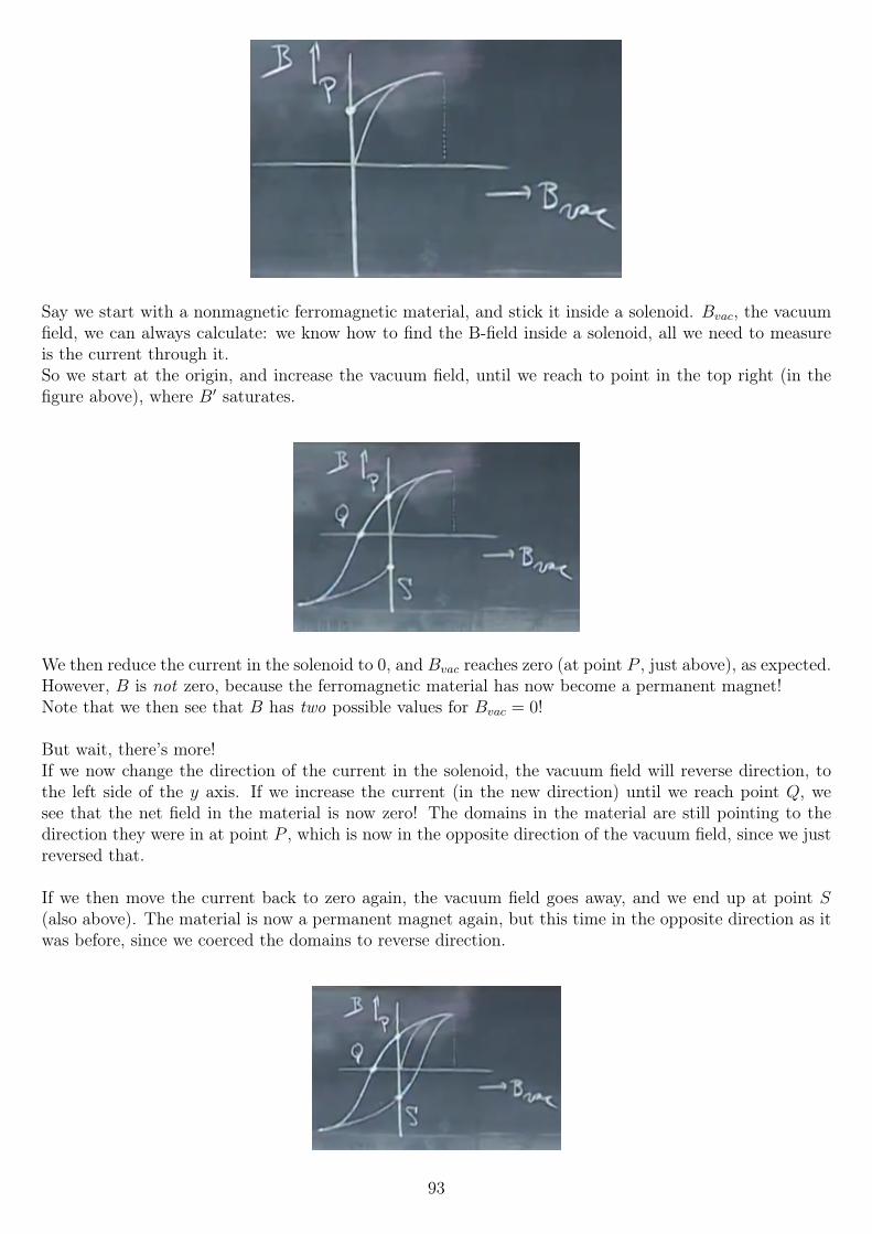
Say we start with a nonmagnetic ferromagnetic material, and stick it inside a solenoid. Bvac, the vacuumfield, we can always calculate: we know how to find the B-field inside a solenoid, all we need to measureis the current through it.So we start at the origin, and increase the vacuum field, until we reach to point in the top right (in thefigure above), where B′ saturates.
We then reduce the current in the solenoid to 0, and Bvac reaches zero (at point P , just above), as expected.However, B is not zero, because the ferromagnetic material has now become a permanent magnet!Note that we then see that B has two possible values for Bvac = 0!
But wait, there’s more!If we now change the direction of the current in the solenoid, the vacuum field will reverse direction, tothe left side of the y axis. If we increase the current (in the new direction) until we reach point Q, wesee that the net field in the material is now zero! The domains in the material are still pointing to thedirection they were in at point P , which is now in the opposite direction of the vacuum field, since we justreversed that.
If we then move the current back to zero again, the vacuum field goes away, and we end up at point S(also above). The material is now a permanent magnet again, but this time in the opposite direction as itwas before, since we coerced the domains to reverse direction.
93
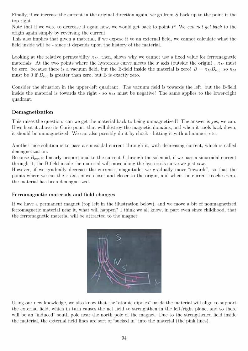
Finally, if we increase the current in the original direction again, we go from S back up to the point it thetop right.Note that if we were to decrease it again now, we would get back to point P ! We can not get back to theorigin again simply by reversing the current.This also implies that given a material, if we expose it to an external field, we cannot calculate what thefield inside will be - since it depends upon the history of the material.
Looking at the relative permeability κM , then, shows why we cannot use a fixed value for ferromagneticmaterials. At the two points where the hysteresis curve meets the x axis (outside the origin) , κM mustbe zero, because there is a vacuum field, but the B-field inside the material is zero! B = κMBvac, so κMmust be 0 if Bvac is greater than zero, but B is exactly zero.
Consider the situation in the upper-left quadrant. The vacuum field is towards the left, but the B-fieldinside the material is towards the right - so κM must be negative! The same applies to the lower-rightquadrant.
Demagnetization
This raises the question: can we get the material back to being unmagnetized? The answer is yes, we can.If we heat it above its Curie point, that will destroy the magnetic domains, and when it cools back down,it should be unmagnetized. We can also possibly do it by shock - hitting it with a hammer, etc.
Another nice solution is to pass a sinusoidal current through it, with decreasing current, which is calleddemagnetization.Because Bvac is linearly proportional to the current I through the solenoid, if we pass a sinusoidal currentthrough it, the B-field inside the material will move along the hysteresis curve we just saw.However, if we gradually decrease the current’s magnitude, we gradually move “inwards”, so that thepoints where we cut the x axis move closer and closer to the origin, and when the current reaches zero,the material has been demagnetized.
Ferromagnetic materials and field changes
If we have a permanent magnet (top left in the illustration below), and we move a bit of nonmagnetizedferromagnetic material near it, what will happen? I think we all know, in part even since childhood, thatthe ferromagnetic material will be attracted to the magnet.
Using our new knowledge, we also know that the “atomic dipoles” inside the material will align to supportthe external field, which in turn causes the net field to strenghthen in the left/right plane, and so therewill be an “induced” south pole near the north pole of the magnet. Due to the strengthened field insidethe material, the external field lines are sort of “sucked in” into the material (the pink lines).
94
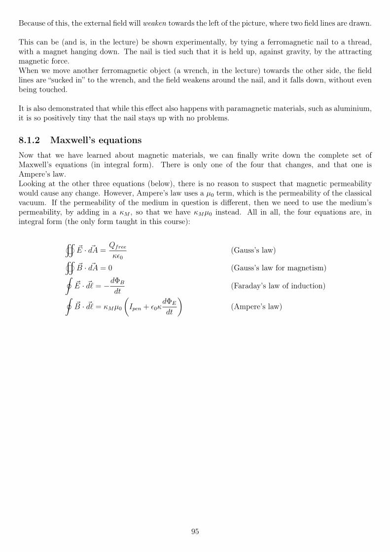
Because of this, the external field will weaken towards the left of the picture, where two field lines are drawn.
This can be (and is, in the lecture) be shown experimentally, by tying a ferromagnetic nail to a thread,with a magnet hanging down. The nail is tied such that it is held up, against gravity, by the attractingmagnetic force.When we move another ferromagnetic object (a wrench, in the lecture) towards the other side, the fieldlines are “sucked in” to the wrench, and the field weakens around the nail, and it falls down, without evenbeing touched.
It is also demonstrated that while this effect also happens with paramagnetic materials, such as aluminium,it is so positively tiny that the nail stays up with no problems.
8.1.2 Maxwell’s equations
Now that we have learned about magnetic materials, we can finally write down the complete set ofMaxwell’s equations (in integral form). There is only one of the four that changes, and that one isAmpere’s law.Looking at the other three equations (below), there is no reason to suspect that magnetic permeabilitywould cause any change. However, Ampere’s law uses a µ0 term, which is the permeability of the classicalvacuum. If the permeability of the medium in question is different, then we need to use the medium’spermeability, by adding in a κM , so that we have κMµ0 instead. All in all, the four equations are, inintegral form (the only form taught in this course):
~E · ~dA =
Qfree
κε0(Gauss’s law)
~B · ~dA = 0 (Gauss’s law for magnetism)∮~E · ~d` = −dΦB
dt(Faraday’s law of induction)∮
~B · ~d` = κMµ0
(Ipen + ε0κ
dΦE
dt
)(Ampere’s law)
95
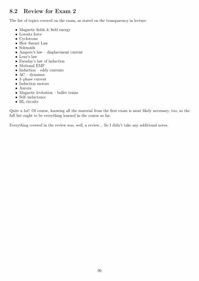
8.2 Review for Exam 2The list of topics covered on the exam, as stated on the transparency in lecture:
• Magnetic fields & field energy• Lorentz force• Cyclotrons• Biot–Savart Law• Solenoids• Ampere’s law – displacement current• Lenz’s law• Faraday’s law of induction• Motional EMF• Induction – eddy currents• AC – dynamos• 3–phase current• Induction motors• Aurora• Magnetic levitation – bullet trains• Self–inductance• RL circuits
Quite a lot! Of course, knowing all the material from the first exam is most likely necessary, too, so thefull list ought to be everything learned in the course so far.
Everything covered in the review was, well, a review... So I didn’t take any additional notes.
96
Chapter 9
Week 9
9.1 Transformers, Car Coils and RC circuits
9.1.1 RC circuits
We previously looked at series RL circuits - circuits with an inductor and a resistor, plus a power sourceand a switch. We will now look at series RC circuits - so the only difference is that we replace the inductorwith a capacitor.
Thus, we have a circuit of a capacitor, resistor, battery with EMF V0, and a switch, going around thecircuit on the blackboard clockwise (not that order matters!).The two nodes the capacitor are connected to are labelled VA and VP , so the capacitor voltage is
VC = VA − VPIntuition goes a long way when it comes to solving this circuit, especially for the simple cases t = 0 andt→∞, just after we close the switch, and when it has been closed for a very, very long time.
Capacitors take time to charge up to a voltage, just as how inductors take time to “charge” with a current.The two circuit elements are duals - as mentioned previously. That means that while inductors take timeto let a current through, with a EMF that goes down to 0 with time, capacitors are the opposite: thecurrent goes to 0 with time, while the voltage increases to its maximum.
So at t = 0, we expect the capacitor to be unchanged (VC = 0), but charging (I = Imax =V0
R).
At t→∞, the current must die down, at which point VC = V0 (otherwise part of the battery’s EMF must
be across the resistor, which means I =V
R6= 0). So at this point, VC = V0 and I = 0.
What about in between? Well, to find the correct answer, let’s get serious and analyze this circuit properly.
The lecture questions asks us to use Faraday’s law, which is unnecessary since there is no changing magneticflux (Kirchhoff’s rule works), but let’s do so.We start “before” the battery and go clockwise, adding whereever the electric field is in the direction weare moving, subtracting otherwise. We find:
−V0 +Q
C+ IR = −dΦB
dt= 0
Alternatively, adding when we go up in potential, subtracting when we go down:
+V0 −Q
C− IR = 0
97
The equations are of course the same, with both sides having been multiplied by −1 in the second case.
We can write I asdQ
dt, which it equals by definition. We then get, rearranged,
Q
C+R
dQ
dt− V0 = 0
... which is a differential equation in one variable. The solution to it, given the initial condition VC(0) = 0,is
Q(t) = V0C
(1− exp
(− t
RC
))Knowing the charge is generally not that useful, but knowing the current is; since current is the timederivative of charge, we differentiate this result with respect to t:
dQ
dt= I(t) = V0C
(1
RCexp
(− t
RC
))I(t) =
V0
Rexp
(− t
RC
)To find the voltage across the capacitor, we simply use the definition of V =
Q
C, and the result for Q we
already found. We divide out the C, and find
VC(t) =Q(t)
C= V0
(1− exp
(− t
RC
))Much like RL circuits, RC circuits also have a time constant τ (tau). In the case of RC circuits, it’s givenby RC, the unit of which is seconds:
Ohm =Volt
Ampere
Farad =Coulomb
Volt
Ohm · Farad =Volt · CoulombAmpere · Volt
=CoulombAmpere
=Ampere · second
Ampere= second
As with RL circuits, after one time constant τ , the values have either gone down to1
eof their initial value,
or up to (1− 1
e) of their maximum, depending on in which direction they are going.
So the potential difference across the capacitor after one time constant τ = RC is ≈ 63.2% of its maximum,while the current is down to ≈ 36.79% of its initial value.
If we now flip the switch in the circuit, such that the capacitor and resistor are in series with nothing elsein there, the capacitor will dischange and its stored energy will be burned as heat in the resistor.
The equation governing that circuit will be
Q
C− IR = 0
98
If we define I to be positive in the opposite direction, this turns into
Q
C+R
dQ
dt= 0
The solution for that differential equation is
Q(t) = V0C exp
(− t
RC
)We use the same tricks (dividing by C and differentiating with respect to t, respectively) to find VC(t) andI(t):
VC(t) =Q(t)
C= V0 exp
(− t
RC
)
dQ
dt= V0C
(− 1
RC
)exp
(− t
RC
)= −V0
Rexp
(− t
RC
)
I(t) = −dQdt
=V0
Rexp
(− t
RC
)So the current will now flow in the counterclockwise direction (remember that we redefined a positive I ascounterclockwise) as opposed to clockwise back when the battery was charging the capacitor.
So to summarize, when charging a capacitor in a simple RC circuit, the following equations apply:
I(t) =V0
Rexp
(− t
RC
)VC(t) = V0
(1− exp
(− t
RC
))When discharging, the following equations apply (assuming it is charged to voltage V0):
I(t) =V0
Rexp
(− t
RC
)VC(t) = V0 exp
(− t
RC
)... where the current is in the opposite direction when discharging.
99
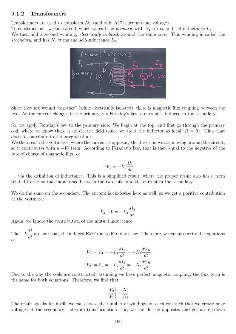
9.1.2 Transformers
Transformers are used to transform AC (and only AC!) currents and voltages.To construct one, we take a coil, which we call the primary, with N1 turns, and self-inductance L1.We then add a second winding, electrically isolated, around the same core. This winding is called thesecondary, and has N2 turns and self-inductance L2.
Since they are wound “together” (while electrically isolated), there is magnetic flux coupling between thetwo. As the current changes in the primary, via Faraday’s law, a current is induced in the secondary.
So, we apply Faraday’s law to the primary side. We begin at the top, and first go through the primarycoil, where we know there is no electric field (since we treat the inductor as ideal, R = 0). Thus thatdoesn’t contribute to the integral at all.We then reach the voltmeter, where the current is opposing the direction we are moving around the circuit,so it contributes with a −V1 term. According to Faraday’s law, that is then equal to the negative of therate of charge of magnetic flux, or
−V1 = −L1dI1
dt
... via the definition of inductance. This is a simplified result, where the proper result also has a termrelated to the mutual inductance between the two coils, and the current in the secondary.
We do the same on the secondary. The current is clockwise here as well, so we get a positive contributionat the voltmeter:
V2 + 0 = −L2dI2
dt
Again, we ignore the contribution of the mutual inductance.
The −LdIdt
are, as usual, the induced EMF due to Faraday’s law. Therefore, we can also write the equationsas
|V1| = E1 = −L1dI1
dt= −N1
dΦB
dt
|V2| = E2 = −L2dI2
dt= −N2
dΦB
dt
Due to the way the coils are constructed, assuming we have perfect magnetic coupling, the flux term isthe same for both equations! Therefore, we find that∣∣∣∣V2
V1
∣∣∣∣ =N2
N1
The result speaks for itself: we can choose the number of windings on each coil such that we create hugevoltages at the secondary - step-up transformation - or, we can do the opposite, and get a step-down
100
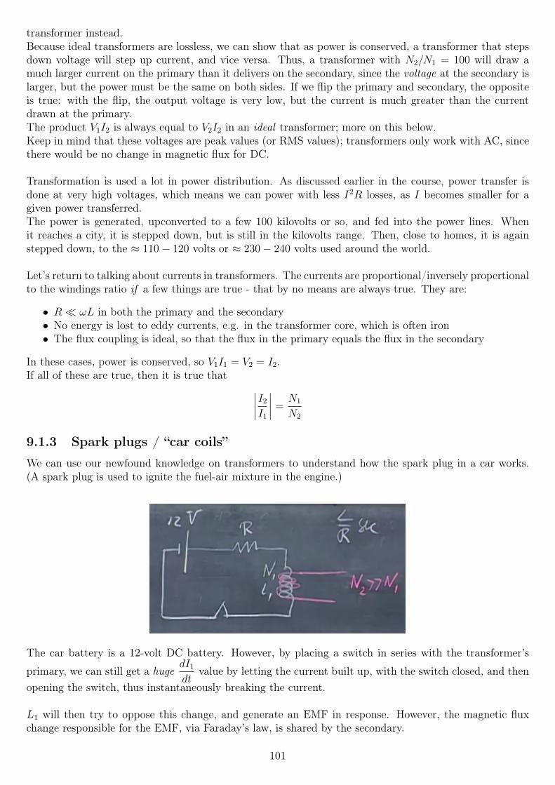
transformer instead.Because ideal transformers are lossless, we can show that as power is conserved, a transformer that stepsdown voltage will step up current, and vice versa. Thus, a transformer with N2/N1 = 100 will draw amuch larger current on the primary than it delivers on the secondary, since the voltage at the secondary islarger, but the power must be the same on both sides. If we flip the primary and secondary, the oppositeis true: with the flip, the output voltage is very low, but the current is much greater than the currentdrawn at the primary.The product V1I2 is always equal to V2I2 in an ideal transformer; more on this below.Keep in mind that these voltages are peak values (or RMS values); transformers only work with AC, sincethere would be no change in magnetic flux for DC.
Transformation is used a lot in power distribution. As discussed earlier in the course, power transfer isdone at very high voltages, which means we can power with less I2R losses, as I becomes smaller for agiven power transferred.The power is generated, upconverted to a few 100 kilovolts or so, and fed into the power lines. Whenit reaches a city, it is stepped down, but is still in the kilovolts range. Then, close to homes, it is againstepped down, to the ≈ 110− 120 volts or ≈ 230− 240 volts used around the world.
Let’s return to talking about currents in transformers. The currents are proportional/inversely propertionalto the windings ratio if a few things are true - that by no means are always true. They are:
• R ωL in both the primary and the secondary• No energy is lost to eddy currents, e.g. in the transformer core, which is often iron• The flux coupling is ideal, so that the flux in the primary equals the flux in the secondary
In these cases, power is conserved, so V1I1 = V2 = I2.If all of these are true, then it is true that ∣∣∣∣I2
I1
∣∣∣∣ =N1
N2
9.1.3 Spark plugs / “car coils”
We can use our newfound knowledge on transformers to understand how the spark plug in a car works.(A spark plug is used to ignite the fuel-air mixture in the engine.)
The car battery is a 12-volt DC battery. However, by placing a switch in series with the transformer’s
primary, we can still get a hugedI1
dtvalue by letting the current built up, with the switch closed, and then
opening the switch, thus instantaneously breaking the current.
L1 will then try to oppose this change, and generate an EMF in response. However, the magnetic fluxchange responsible for the EMF, via Faraday’s law, is shared by the secondary.
101
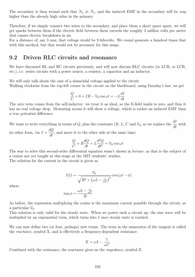
The secondary is then wound such that N2 N1, and the induced EMF in the secondary will be wayhigher than the already high value in the primary.
Therefore, if we simply connect two wires to the secondary, and place them a short space apart, we willget sparks between them if the electric field between them exceeds the roughly 3 million volts per meterthat causes electric breakdown in air.For a distance of, say 3 mm, that voltage would be 9 kilovolts. We cound generate a hundred times thatwith this method, but that would not be necessary for this usage.
9.2 Driven RLC circuits and resonanceWe have discussed RL and RC circuits previously, and will now discuss RLC circuits (or LCR, or LCR,etc.), i.e. series circuits with a power source, a resistor, a capacitor and an inductor.
We will only talk about the case of a sinusoidal voltage applied to the circuit.Walking clockwise from the top-left corner in the circuit on the blackboard, using Faraday’s law, we get
Q
C+ 0 + IR− V0 cosωt = −LdI
dt
The zero term comes from the self-inductor: we treat it as ideal, so the E-field inside is zero, and thus ithas no real voltage drop. Measuring across it will show a voltage, which is rather an induced EMF thana true potential difference.
We want to write everything in terms of Q, plus the constants (R, L, C and V0, so we replace thedI
dtwith
its other form, via I =dQ
dt, and move it to the other side at the same time:
Q
C+R
dQ
dt+ L
d2Q
dt2= V0 cosωt
The way to solve this second-order differential equation wasn’t shown in lecture, as that is the subject ofa course not yet taught at this stage at the MIT students’ studies.The solution for the current in the circuit is given as
I(t) =V0√
R2 +(ωL− 1
ωC
)2cos (ωt− φ)
where
tanφ =ωL− 1
ωC
R
As before, the expression multiplying the cosine is the maximum current possible through the circuit, ata particular V0.This solution is only valid for the steady state. When we power such a circuit up, the sine wave will bemultiplied by an exponential term, which turns into 1 once steady state is reached.
We can now define two (or four, perhaps) new terms. The term in the numerator of the tangent is calledthe reactance, symbol X, and is effectively a frequency-dependent resistance:
X = ωL− 1
ωC
Combined with the resistance, the reactance gives us the impedance, symbol Z:
102
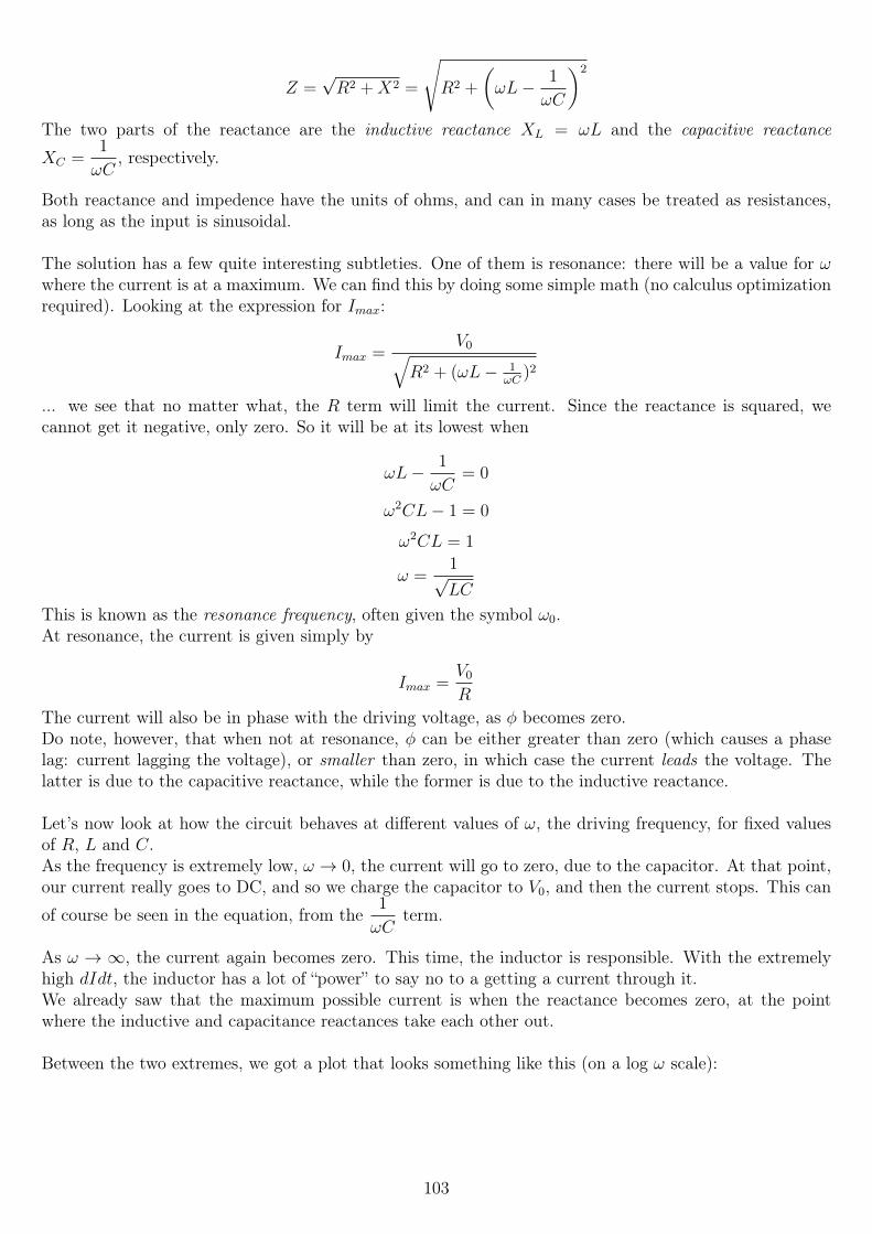
Z =√R2 +X2 =
√R2 +
(ωL− 1
ωC
)2
The two parts of the reactance are the inductive reactance XL = ωL and the capacitive reactance
XC =1
ωC, respectively.
Both reactance and impedence have the units of ohms, and can in many cases be treated as resistances,as long as the input is sinusoidal.
The solution has a few quite interesting subtleties. One of them is resonance: there will be a value for ωwhere the current is at a maximum. We can find this by doing some simple math (no calculus optimizationrequired). Looking at the expression for Imax:
Imax =V0√
R2 + (ωL− 1ωC
)2
... we see that no matter what, the R term will limit the current. Since the reactance is squared, wecannot get it negative, only zero. So it will be at its lowest when
ωL− 1
ωC= 0
ω2CL− 1 = 0
ω2CL = 1
ω =1√LC
This is known as the resonance frequency, often given the symbol ω0.At resonance, the current is given simply by
Imax =V0
R
The current will also be in phase with the driving voltage, as φ becomes zero.Do note, however, that when not at resonance, φ can be either greater than zero (which causes a phaselag: current lagging the voltage), or smaller than zero, in which case the current leads the voltage. Thelatter is due to the capacitive reactance, while the former is due to the inductive reactance.
Let’s now look at how the circuit behaves at different values of ω, the driving frequency, for fixed valuesof R, L and C.As the frequency is extremely low, ω → 0, the current will go to zero, due to the capacitor. At that point,our current really goes to DC, and so we charge the capacitor to V0, and then the current stops. This can
of course be seen in the equation, from the1
ωCterm.
As ω → ∞, the current again becomes zero. This time, the inductor is responsible. With the extremelyhigh dIdt, the inductor has a lot of “power” to say no to a getting a current through it.We already saw that the maximum possible current is when the reactance becomes zero, at the pointwhere the inductive and capacitance reactances take each other out.
Between the two extremes, we got a plot that looks something like this (on a log ω scale):
103
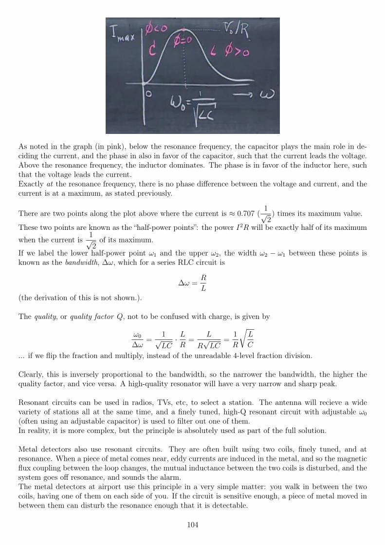
As noted in the graph (in pink), below the resonance frequency, the capacitor plays the main role in de-ciding the current, and the phase in also in favor of the capacitor, such that the current leads the voltage.Above the resonance frequency, the inductor dominates. The phase is in favor of the inductor here, suchthat the voltage leads the current.Exactly at the resonance frequency, there is no phase difference between the voltage and current, and thecurrent is at a maximum, as stated previously.
There are two points along the plot above where the current is ≈ 0.707 (1√2) times its maximum value.
These two points are known as the “half-power points”: the power I2R will be exactly half of its maximum
when the current is1√2of its maximum.
If we label the lower half-power point ω1 and the upper ω2, the width ω2 − ω1 between these points isknown as the bandwidth, ∆ω, which for a series RLC circuit is
∆ω =R
L(the derivation of this is not shown.).
The quality, or quality factor Q, not to be confused with charge, is given by
ω0
∆ω=
1√LC· LR
=L
R√LC
=1
R
√L
C
... if we flip the fraction and multiply, instead of the unreadable 4-level fraction division.
Clearly, this is inversely proportional to the bandwidth, so the narrower the bandwidth, the higher thequality factor, and vice versa. A high-quality resonator will have a very narrow and sharp peak.
Resonant circuits can be used in radios, TVs, etc, to select a station. The antenna will recieve a widevariety of stations all at the same time, and a finely tuned, high-Q resonant circuit with adjustable ω0
(often using an adjustable capacitor) is used to filter out one of them.In reality, it is more complex, but the principle is absolutely used as part of the full solution.
Metal detectors also use resonant circuits. They are often built using two coils, finely tuned, and atresonance. When a piece of metal comes near, eddy currents are induced in the metal, and so the magneticflux coupling between the loop changes, the mutual inductance between the two coils is disturbed, and thesystem goes off resonance, and sounds the alarm.The metal detectors at airport use this principle in a very simple matter: you walk in between the twocoils, having one of them on each side of you. If the circuit is sensitive enough, a piece of metal moved inbetween them can disturb the resonance enough that it is detectable.
104

9.3 Traveling waves and standing waves
9.3.1 Traveling waves
Say we have a very simple equation, such as
y =1
3x
and we want to make it “move” towards the right, at a certain velocity v = 6.All we have to do to make this happen is to replace x with x− vt, so we have
y =1
3(x− vt) =
x
3− 2t
At t = 0, this simplifies down to the original equation, At t > 0, the equation will be shifted, and ifgraphed, it will have moved towards the right.
Replace the minus sign in x − vt with a plus sign, and it will instead move towards the left, again withvelocity v.
Let’s look at a different function: y = 2 sin(3x). This time, we have a proper wave.
On this plot, we measure the wavelength λ (Greek lowercase lambda) as the length of a full cycle, so thetime between one peak and the next, or one trough and the next (or any two similar points).
In this example, the wavelength is λ =2π
3.
We also introduce the symbol k for the wave number, defined as k =2π
λ, so k = 3 for this case. So k is
then the number multiplying x in the sine function.
Now, can we make this wave move, in the same manner as we did with the line? Indeed, we do as we didbefore: we replace x with x− vt. For v = 6 m/s again, we find
y = 2 sin(3(x− 6t))
There is more information in this equation: the 2 multiplying the sine gives us the amplitude. The 3, the
wave number, tells us the wavelength (via k =2π
λ, so λ =
2π
k), and the 6 tells us the velocity. The minus
sign also tells us that it is travelling towards the right. Thus the equation is of the form
y = A sin(k(x− vt))
If we attach a rope to a spinning wheel, we can create a traveling wave, propagating in the rope.
Say the wheel rotates with angular frequency ω. The period of one wave will as always be T =2π
ω. One
wavelength λ is as always the length between two peaks of the wave, or the distance traveled during one
105
period, which is simply λ = vT , which also equals =v
f, where f is the frequency in hertz (f =
1
T, and
ω = 2πf). It’s then also true that f =v
λ.
We can write the equation in a different form:
y = A sin(kx− ωt)
Via the conversion formulas we just found, this too contains all the information. k gives the spatial in-formation, such as λ. ω gives the angular frequency/frequency/period/velocity, either alone or combinedwith k: v =
ω
k
As an example, let’s look at the equation
y = 4 sin(2(3x− 9t))
If we multiply it out, we get
y = 4 sin(6x− 18t)
... which tells us k = 6 and ω = 18, traveling towards the right.
Thus the amplitude is A = 4, the velocity v =ω
k= 3 m/s. The wavelength is λ = vT = v
2π
ω=
2π
318 =
π
3,
and the frequency f =ω
2π=
9
π.
9.3.2 Standing waves
Say we have a wave
y1 = y0 sin(kx− ωt)
which is the travelling towards the right. However, we also have a second wave, identical except for a plussign, which tells us it is travelling towards the left:
y2 = y0 sin(kx+ ωt)
Via trigonometric identities, the sum of these is
y = y1 + y2 = 2y0 sin(kx) cos(ωt)
This is a standing wave. If we plot it at various values of t, we find that some points, called nodes, are
completely fixed: their y-value is fixed. These points occur at multiples ofλ
2.
All points along the curve that are not nodes will move up and down, but not towards the left or towardsthe right - note that there is no x − t anywhere any more. So the sinusoid will essentially bob up anddown, while standing still.
We can make standing waves in a similar fashion to making traveling waves, but we need to get the fre-quency of them just right.Say we have a length of string, and we hold it fixed at the ends, so the ends become nodes.It is held by two people, and one of them is moving their “node” up and down slightly (which makes it nota node, but with small movements, we can ignore that). When the wave reaches the end of the string, itwill reflect back towards the first person. When it comes back to the first person, it will again reflect, etc.If the conditions are right, these reflections can support each other, and the amplitude will increase. Thishappens at a set of frequencies, which we call the resonance frequencies, in a similar fashion to RLC
106

circuits. However, in this case, there are in theory an infinite amount of such frequencies.
For the lowest possible such frequency, which we call the fundamental (or first harmonic), there will benodes at the ends of the string, but nowhere else. Thus the length of the string will be half the wavelength- or, the wavelength will be twice the string’s length.
For the next possible frequency, the second harmonic, the frequency is exactly twice that of the first har-monic. Here, there will be a node at the exact center of the string, which will not move at all. So now wehave three nodes: one at each end, plus one at the exact center.
For the third harmonic, the frequency is exactly three times the first harmonic’s frequency, and there willbe another node, splitting the string into 3 parts that move, with a total of 4 nodes (one at each end, oneat 1/3 of the string’s length, and one at 2/3 the string’s length).
There are always n+ 1 nodes for the nth harmonic, assuming we count nodes at the string ends.
The fundamental, denoted by 1, is then 2L, where L is the length of the string, as we stated above.The frequency of the fundamental, f1, is given by f1 =
v
λin general, so in this case, f1 =
v
2L.
For the second harmonic, λ2 = L, which follows from f2 = 2f1 (or from drawing it out, in which case it isimmediately obvious).In general, then,
λn =2L
n
fn =v
λn= nf1 =
nv
2L
9.3.3 Musical instruments
When we “excite” a string in an instruments — whether it is a string inside a piano being hit by a hammer,a guitar string hit by a guitar pick, or a violin string hit by a bow — it will be exposed to a whole rangeof frequencies. However, it will tend to oscillate only in the resonant frequencies, which is why we can getwell-tuned sound out of such instruments.So a ring that has a resonant frequency of 400 Hz, when struck, will tend to oscillate at 400 Hz, 800 Hz,1200 Hz etc., all at the same time.
So for designing a stringed musical instrument, a key equation is
f1 =v
2L
v is decided by the string’s material and tension:
v =
√Tension
Mass/length
(proved in the next MIT physics course, 8.03 “Vibrations and Waves”, not here).
A regular steel-stringed guitar usually has roughly the same tension for all strings, something on the orderof 7-10 kg-force of tension per string for a 6-string guitar in standard tuning, with standard string gauges.The difference between the strings is then mostly in their material - indeed, they usually all differ in thick-ness, from 0.010" for the thinnest E string, to 0.046" for the thickest. (Different guitarists have differenttastes; 0.009"-0.0042" is about the thinnest anyone uses, and they can go up to about 0.013"-0.056", still
107
in standard tuning, which then causes much more tension).
The tension is what we adjust when we tune a stringed instruments - we wind the string either more (moretension) or less, until it resonates at the (fundamental) frequency we want.When we play the instrument, we change the string’s length, by shortening it with our fingers.On fretted instruments, like guitars and electric basses, the string is shortened by a metal bar (the fret)going across the neck; there are usually 17-24 such frets on a guitar.
The instrument’s sound is then generated as the string vibrates, which pushes and pulls on the surroundingair, creating pressure waves in the air. Those pressure waves eventually reach our ear drums, and causesthe ear drums to vibrate at the same frequencies. That is then interpreted as sound by the ear and ourbrains.
Let’s now discuss wind instruments.Say we have a completely closed box, of length L. At the left end of the box, we put a loudspeaker, whichgenerates a certain sound frequency.We can now get resonance, and a standing wave, in the air inside the box. The frequencies are goverenedby the same equation as for the stringed instruments, except that v is now fixed: it is the speed of soundin the air inside the box.
We can’t do much about the temperature - but if it does change, the fundamental of the instrument willalso change. This can be compensated for by adjusting L to cancel out the error, if applicable to theinstrument.Because of the equation that governs them (above), the smaller L is, the higher the fundamental frequency.Therefore a trombone, which is large, has a lower frequency than a trumpet, which is smaller. A tuba hasan even lower frequency sound.
For a flute, if you cover all the drilled holes on it, the “resonant chamber” will be long, and the frequencywill be low. If you take your fingers off the holes, so that they are open, the frequency will go up.
108
Chapter 10
Week 10
10.1 Resonance, electromagnetic wavesThe lecture begins with talk about mechanical resonance, without much math or things to take notes of.It is demonstrated how playing a loud tone at a wine glass’s resonance frequency can shatter the glass.After that, a movie is shown about the Tacoma Narrows Bridge, that collapsed only 4 months after itsconstruction in 1940.The bridge resonated with the wind, such that huge waves went along it. On the day of its collapse, itwent into a “twisting” motion that proved too much for it to handle, and the bridge collapsed. I wouldrecommend looking up footage of this on the internet, as the collapse was actually filmed.
Let’s now turn to electromagnetic waves. Two of Maxwell’s equations are extra important here:
∮~E · ~d` = −dΦB
dt(Faraday’s law)∮
~B · ~d` = µ0κm
(I + ε0κ
dΦE
dt
)(Ampere-Maxwell law)
At least to begin with, we will introduce EM waves without the rigorous differential equation treatment.As the above equations show, we can get an electric field due to a changing magnetic field (Faraday’s law).Not only that, but we can also get a magnetic field due to a changing electric field (the Ampere-Maxwelllaw).
One possible EM wave that meets all four of Maxwell’s equations is
~E = E0x cos(kz − ωt)~B = B0y cos(kz − ωt)
Thus, the electric field is solely in the x direction, the magnetic field solely in the y direction, while thewave propagates in the (positive) z direction, as seen by the term inside the cosine. Furthermore, we seethat they have the same frequency/wavelength, and that they are in phase with each other. That is, whenE = 0, B = 0, and when E = E0 (the maximum value), B = B0, etc.
The wave propagates with v = ωk
= c, with c being the symbol for the speed of light (in a vacuum), about3 · 108 m/s (to within 0.07%!).The equations above are for a plane wave. If we take a plane perpendicular to z, at a single moment intime, the E and B vectors are the same everywhere in that plane. They satisfy Maxwell’s equations onlyif
B0 =E0
c
109
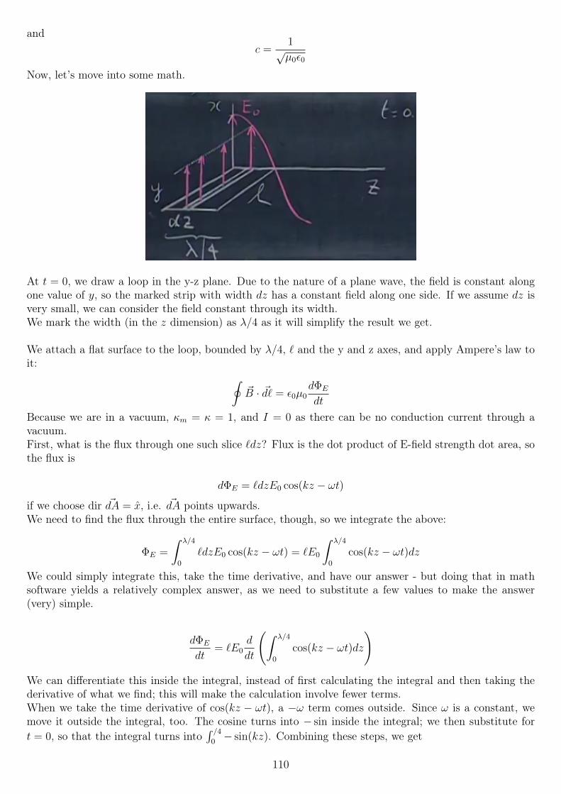
andc =
1√µ0ε0
Now, let’s move into some math.
At t = 0, we draw a loop in the y-z plane. Due to the nature of a plane wave, the field is constant alongone value of y, so the marked strip with width dz has a constant field along one side. If we assume dz isvery small, we can consider the field constant through its width.We mark the width (in the z dimension) as λ/4 as it will simplify the result we get.
We attach a flat surface to the loop, bounded by λ/4, ` and the y and z axes, and apply Ampere’s law toit: ∮
~B · ~d` = ε0µ0dΦE
dt
Because we are in a vacuum, κm = κ = 1, and I = 0 as there can be no conduction current through avacuum.First, what is the flux through one such slice `dz? Flux is the dot product of E-field strength dot area, sothe flux is
dΦE = `dzE0 cos(kz − ωt)
if we choose dir ~dA = x, i.e. ~dA points upwards.We need to find the flux through the entire surface, though, so we integrate the above:
ΦE =
∫ λ/4
0
`dzE0 cos(kz − ωt) = `E0
∫ λ/4
0
cos(kz − ωt)dz
We could simply integrate this, take the time derivative, and have our answer - but doing that in mathsoftware yields a relatively complex answer, as we need to substitute a few values to make the answer(very) simple.
dΦE
dt= `E0
d
dt
(∫ λ/4
0
cos(kz − ωt)dz
)We can differentiate this inside the integral, instead of first calculating the integral and then taking thederivative of what we find; this will make the calculation involve fewer terms.When we take the time derivative of cos(kz − ωt), a −ω term comes outside. Since ω is a constant, wemove it outside the integral, too. The cosine turns into − sin inside the integral; we then substitute fort = 0, so that the integral turns into
∫ /40− sin(kz). Combining these steps, we get
110
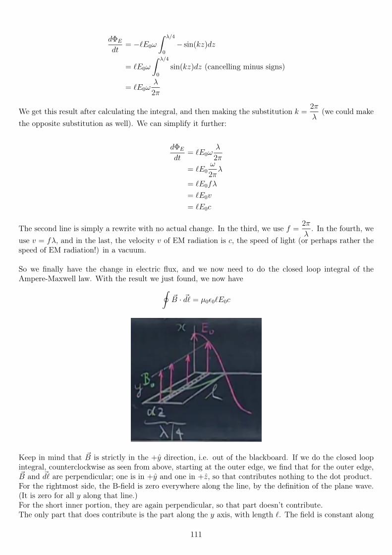
dΦE
dt= −`E0ω
∫ λ/4
0
− sin(kz)dz
= `E0ω
∫ λ/4
0
sin(kz)dz (cancelling minus signs)
= `E0ωλ
2π
We get this result after calculating the integral, and then making the substitution k =2π
λ(we could make
the opposite substitution as well). We can simplify it further:
dΦE
dt= `E0ω
λ
2π
= `E0ω
2πλ
= `E0fλ
= `E0v
= `E0c
The second line is simply a rewrite with no actual change. In the third, we use f =2π
λ. In the fourth, we
use v = fλ, and in the last, the velocity v of EM radiation is c, the speed of light (or perhaps rather thespeed of EM radiation!) in a vacuum.
So we finally have the change in electric flux, and we now need to do the closed loop integral of theAmpere-Maxwell law. With the result we just found, we now have∮
~B · ~d` = µ0ε0`E0c
Keep in mind that ~B is strictly in the +y direction, i.e. out of the blackboard. If we do the closed loopintegral, counterclockwise as seen from above, starting at the outer edge, we find that for the outer edge,~B and ~d` are perpendicular; one is in +y and one in +z, so that contributes nothing to the dot product.For the rightmost side, the B-field is zero everywhere along the line, by the definition of the plane wave.(It is zero for all y along that line.)For the short inner portion, they are again perpendicular, so that part doesn’t contribute.The only part that does contribute is the part along the y axis, with length `. The field is constant along
111
that line - again, definition of a plane wave, so that part simply contributes B0`. So with the integralevaluating to that simple value, we find
B0` = µ0ε0`E0 c
B0 = µ0ε0E0 c
The ` cancels, and we find a relation between the two field strengths.
The following properties are always true of traveling EM waves:
~E ⊥ ~v~B ⊥ ~v~E ⊥ ~B
~E and ~B are in phase
E × B = v
~B =E0
c
c =1
√µ0ε0
The second-last one does not contradict our finding above, because of the last one. We can solve the twoas a system of equations and will find the value for c shown, which means that the two equations are reallyequivalent.
We know that electromagnetic waves travel at (propagate at) c ≈ 3 · 108 m/s, we can then calculate somerough times required to move certain distances.
One foot takes about a nanosecond. 30 meters, the length of the lecture hall where the lecture is recorded,about 0.1 microsecond. In one second, it can move all the way to the moon, and about eight minutes tothe sun. That is, it takes light 8 minutes to move between the surface of the sun and the Earth.The closest star (except for the sun, of course!), Proxima Centauri, is about 4.2 lightyears away, so lightwould (by the definition of a lightyear) take light 4.2 years to travel to us from there.The nearest large galaxy, the Andromeda galaxy, is about 2.5 million lightyears away. When we look atit in the sky, we see it as it were 2.5 million years ago!
Since one year is (in the definition used) 365.25 days (on average), one year is 365.25 ·24 ·60 ·60 = 31557600seconds, so multiplying that by the speed of light, we find that one light year is about 9.46 · 1015 meters.
10.1.1 Radar and measuring distance
We can measure distances by measuring how long it takes for light to reflect off a target.We sent a pulse, and begin measuring the time taken. When the reflection returns, we stop measuring,and calculate the distance as
2d = ct
d =ct
2
where t is the measured time, and c is as usual the speed of light. We have to divide by two since the lighthas travelled both there and back, and we only want the one-way distance.We can measure the distance to the moon in this way, by sending focused laser pulses. Astronauts fromboth the US Apollo missions and the Soviets have left corner reflectors / retroreflectors on the moon.
112
These devices reflect light back in the exact direction it came from - as opposed to a mirror/mirror-likesurface, where the angle would be of the same magnitude, but the reflection would only come back if youlooked at it exactly straight on.
10.1.2 Radio
Now to something slightly different: radio, as in both radio waves and radio stations. An AM radio stationmight transmit somewhere in the 1000-1000 kHz range (as an order of magnitude). How is audible sound,<20 kHz, transmitted that way?Well, we use AM: amplitude modulation. First, we generate a carrier wave, a high-frequency sinusoid.The frequency of the carrier wave is the frequency a listener will have to tune in to.We then modulate that signal, by changing its amplitude, by essentially simply multiplying the twofrequencies. Thus we will end up with a signal that is of the (simplified, not truly accurate) form
y = sin(2π106t) cos(2π103t)
To listen to such a station, we tune an RLC circuit in our radio to the carrier frequency, such that it is atresonance only at the frequency we want to listen to. (We need a high-Q / low-bandwidth resonator forthis, or we might pick out nearby stations as well!)After that, we need to demodulate the signal, to get only the envelope, which is what was the signal tobegin with (at the radio station).
10.2 Index of refraction and Poynting vector
10.2.1 Poynting vector
Let’s now look at the energy content of electromagnetic waves. We have seen earlier that electric fieldsand magnetic fields both have an associated energy density, given by
UE =1
2ε0E
2 J/m3
UB =1
2µ0B
2 =1
2µ0
E2
c2J/m3
The latter follows from the equivalence B0 =E0
cthat we found earlier.
However,
c =1
√µ0ε0
c2 =1
µ0ε0
Therefore,
UB =1
2µ0
E2µ0ε0 =1
2ε0E
2 J/m3
So the energy denssity of the B-field is exactly the same as the energy density of the E-field in EM waves!The total energy density is then the sum, so we just get rid of the one-half, ane we find
Utotal = ε0E2 = ε0EBc
where we use that E = Bc (via B =E
c).
113
Now that we know that EM waves carry some energy, we can ask the question: if an EM wave passesthrough a surface, how much energy passes through one square meter per second? That is, what is theenergy flux, in watts per square meter (joules per second per square meter)?
Imagine a square surface, of side one meter, perpendicular in space to the wave’s propagation. Thus, thedot product works out to not have the cosine term, as that would equal one (cos θ = cos 0 = 1).
Since light travels a distance of c meters in one second, we can calculate the energy stored in a “box” thatgoes back such a distance from the square we are interested in. We know that all energy inside this boxwill pass through the square, so we calculate the total energy by multiplying the energy density by c · 1 · 1cubic meters, and find
Utotal · c = ε0EBc2
Because c2 =1
µ0ε0, that is equivalent to
Utotal · c =EB
µ0
The unit of this is then (as noted above) watts per square meter, orJ
m2 · s.
What we have found is called the Poynting vector, named after its inventor (though it was simultanesouslycreated by others, as well). The pronunciation is very close to “pointing vector” (many likely say it exactlylike that), perhaps with a bit more of the “y” sound. It is generally written as
~S =~E × ~B
µ0
~E and ~B are always perpendicular in a traveling EM wave, so the cross product can be seen as being there
only to provide the direction; the magnitude is always |~S| = EB
µ0
.
~E and ~B are not constant in value, however! They are sinusoidal in nature, and so the Poynting vectormust be described by a sin2 or cos2 function.We can think about its time averaged value, which may be more useful, since it varies constantly (andusually with extremely high frequency - visible light is in the 1014 Hz range, for example!).The time average of a sin2 or cos2 is one half the maximum, so we find
〈S〉 =1
2
E0B0
µ0
=1
2
E02
µ0c
10.2.2 Waves due to accelerating charges
Now that we have learned a bit about plane waves, let’s look at some other types. Plane waves are usefulfor modelling some situations, but far from all.Given the equation for a plane wave, we can calculate its value for any time, past or present, at any pointin space, no matter how distant. That’s not too realistic.
Let’s look at the electric field lines of an accelerating point charge.
114
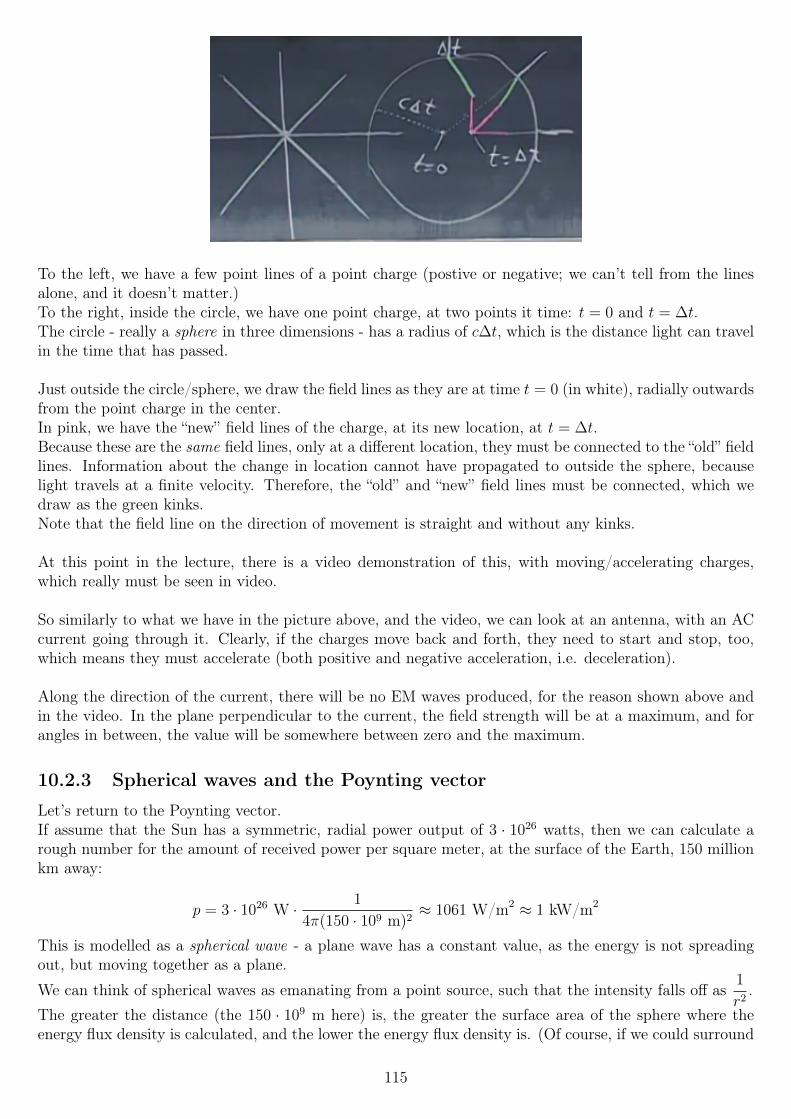
To the left, we have a few point lines of a point charge (postive or negative; we can’t tell from the linesalone, and it doesn’t matter.)To the right, inside the circle, we have one point charge, at two points it time: t = 0 and t = ∆t.The circle - really a sphere in three dimensions - has a radius of c∆t, which is the distance light can travelin the time that has passed.
Just outside the circle/sphere, we draw the field lines as they are at time t = 0 (in white), radially outwardsfrom the point charge in the center.In pink, we have the “new” field lines of the charge, at its new location, at t = ∆t.Because these are the same field lines, only at a different location, they must be connected to the “old” fieldlines. Information about the change in location cannot have propagated to outside the sphere, becauselight travels at a finite velocity. Therefore, the “old” and “new” field lines must be connected, which wedraw as the green kinks.Note that the field line on the direction of movement is straight and without any kinks.
At this point in the lecture, there is a video demonstration of this, with moving/accelerating charges,which really must be seen in video.
So similarly to what we have in the picture above, and the video, we can look at an antenna, with an ACcurrent going through it. Clearly, if the charges move back and forth, they need to start and stop, too,which means they must accelerate (both positive and negative acceleration, i.e. deceleration).
Along the direction of the current, there will be no EM waves produced, for the reason shown above andin the video. In the plane perpendicular to the current, the field strength will be at a maximum, and forangles in between, the value will be somewhere between zero and the maximum.
10.2.3 Spherical waves and the Poynting vector
Let’s return to the Poynting vector.If assume that the Sun has a symmetric, radial power output of 3 · 1026 watts, then we can calculate arough number for the amount of received power per square meter, at the surface of the Earth, 150 millionkm away:
p = 3 · 1026 W · 1
4π(150 · 109 m)2≈ 1061 W/m2 ≈ 1 kW/m2
This is modelled as a spherical wave - a plane wave has a constant value, as the energy is not spreadingout, but moving together as a plane.
We can think of spherical waves as emanating from a point source, such that the intensity falls off as1
r2.
The greater the distance (the 150 · 109 m here) is, the greater the surface area of the sphere where theenergy flux density is calculated, and the lower the energy flux density is. (Of course, if we could surround
115
the entire sun, then we would capture the entire output regardless of the radius of our sphere, just thatthe energy flux per square meter of the sphere would be lower for greater radii.)
If we instead think of this as a plane wave, we can calculate the equivalent electric field:
1000 =E0
2
µ0c
E0 ≈ 613 V/m
(the lecture says 870 V/m, but I’m not sure how that number is found!)Regardless of the exact number, what does this represent? Well, it’s some equivalent E-field value, thatwould produce this energy flux if it were a plane wave. Is that useful? Perhaps, perhaps not, dependingon what we are trying to do.We can often choose a model to use - plane waves, spherical waves, individual photons - to explain somephenomenon.
10.2.4 Photons and radiation pressure
Next, let’s have a look at photons. Photons are individual light particles - “quanta” of light. Each photonhas a certain frequency, and a certain energy (the energy is proportional to the frequency).Because photons have energy, they have momentum - despite having no mass!In classical mechanics, the magnitude of momentum is given by p = mv, which clearly must be 0 for amassless particle.The answer comes from Einstein’s relativity, and “the world’s most famous equation”... except the famousform is simplified:
E = mc2
This is only a special case of the full version:
E2 = p2c2 +m2c4
Thus, for a photon, with mass m = 0, we find
E2 = p2c2
E = pc
p =E
c
(E = mc2 is the special case where p = 0, for a body it its rest frame.)
So we see that the momentum of a photon is given by the energy it carries, divided by the speed of light.
But now, something else happens: the transfer of momentum is what we call force (~F =d~p
dt- Newton’s
second law)!So say we have a square meter, perpendicular to some incoming EM radiation (at a wavelength that wouldbe absorbed by the surface). Using the Poynting vector, we have
S =energym2 · s
If we divide both sides by c, we find
S
c=
energyc ·m2 · s
We find that E/c term again, which is the momentum. So this can be rewritten as
116
S
c=
momentumm2 · s
The units of this is then momentum per unit time, which is force, per square meter, which is pressure.We call this pressure radiation pressure. So what this is saying is that for a given area, with a certainamount of incoming EM radiation perpendicular to it, there will be a force proportional to the area, andproportional to the energy contained in each photon, pushing this surface “backwards” (in the same direc-tion as the radiation wave is propagating).
Keeping in mind that the time-average value of the Poynting vector is what we are really interested in, wecan write the pressure as
p =〈S〉cα
where
α =
0, if the material is entirely transparent to the radiation,1, if 100% of the radiation is absorbed,2, if 100% of the radiation is reflected
Of course, values in between are also possible.The reason for these values can be seen quite easily from the conservation of momentum.The professor used the examples of throwing tomatoes earlier in the lecture, so we will use that mechanicalanalogue.Since classical momentum is the product of mass and velocity, a (very large!) tomato of mass 1 kg, movingat 5 m/s, will have a momentum of 5 newton-seconds. If one such tomato hits a target per second, andfalls straight down after hitting, a force of 5 newtons will be applied to the target.If the tomato were instead somehow bouncing back, in a perfectly elastic collision, then the force wouldbe twice that: first the momentum is “absorbed” by the target, and then it must add the same magnitudeof momentum back in the opposite direction, so the transfer of momentum is twice as large.
In between the lecture segments, we have the following question:“What is the radiation pressure on a spherical iron asteroid of approximate radius 100 m? The asteroid isat a distance of about 400 million km from the sun. Assume that all radiation is absorbed. Again assumethat the power output of the Sun is 3 × 1026 W as shown in the lecture (note that the actual measuredvalue is closer to 3.8× 1026 W).”We take the Sun’s power output to be spherically symmetric, so the energy flux density at the distance is
〈S〉 = 3 · 1026 · 1
4π(400 · 109 m)2≈ 149.2 W/m2
We divide that by c, and find the radiation pressure:
p ≈ 149.2
3 · 108≈ 5 · 10−7 N/m2
The pressure will only be on half the asteroid, as only one side is facing the Sun.While we will find a half-decent approximation by multiplying the area facing the sun (2πr2) with thepressure, we really need to consider that parts of that area are almost entirely parallel to the pressure,while the area near the asteroid’s center will be mostly perpendicular.
F = πr2p
We can then calculate the force due to the radiation pressure:
117
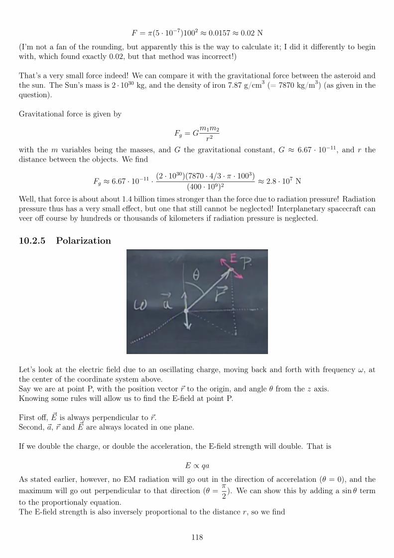
F = π(5 · 10−7)1002 ≈ 0.0157 ≈ 0.02 N
(I’m not a fan of the rounding, but apparently this is the way to calculate it; I did it differently to beginwith, which found exactly 0.02, but that method was incorrect!)
That’s a very small force indeed! We can compare it with the gravitational force between the asteroid andthe sun. The Sun’s mass is 2 · 1030 kg, and the density of iron 7.87 g/cm3 (= 7870 kg/m3) (as given in thequestion).
Gravitational force is given by
Fg = Gm1m2
r2
with the m variables being the masses, and G the gravitational constant, G ≈ 6.67 · 10−11, and r thedistance between the objects. We find
Fg ≈ 6.67 · 10−11 · (2 · 1030)(7870 · 4/3 · π · 1003)
(400 · 109)2≈ 2.8 · 107 N
Well, that force is about about 1.4 billion times stronger than the force due to radiation pressure! Radiationpressure thus has a very small effect, but one that still cannot be neglected! Interplanetary spacecraft canveer off course by hundreds or thousands of kilometers if radiation pressure is neglected.
10.2.5 Polarization
Let’s look at the electric field due to an oscillating charge, moving back and forth with frequency ω, atthe center of the coordinate system above.Say we are at point P, with the position vector ~r to the origin, and angle θ from the z axis.Knowing some rules will allow us to find the E-field at point P.
First off, ~E is always perpendicular to ~r.Second, ~a, ~r and ~E are always located in one plane.
If we double the charge, or double the acceleration, the E-field strength will double. That is
E ∝ qa
As stated earlier, however, no EM radiation will go out in the direction of accerelation (θ = 0), and themaximum will go out perpendicular to that direction (θ =
π
2). We can show this by adding a sin θ term
to the proportionaly equation.The E-field strength is also inversely proportional to the distance r, so we find
118
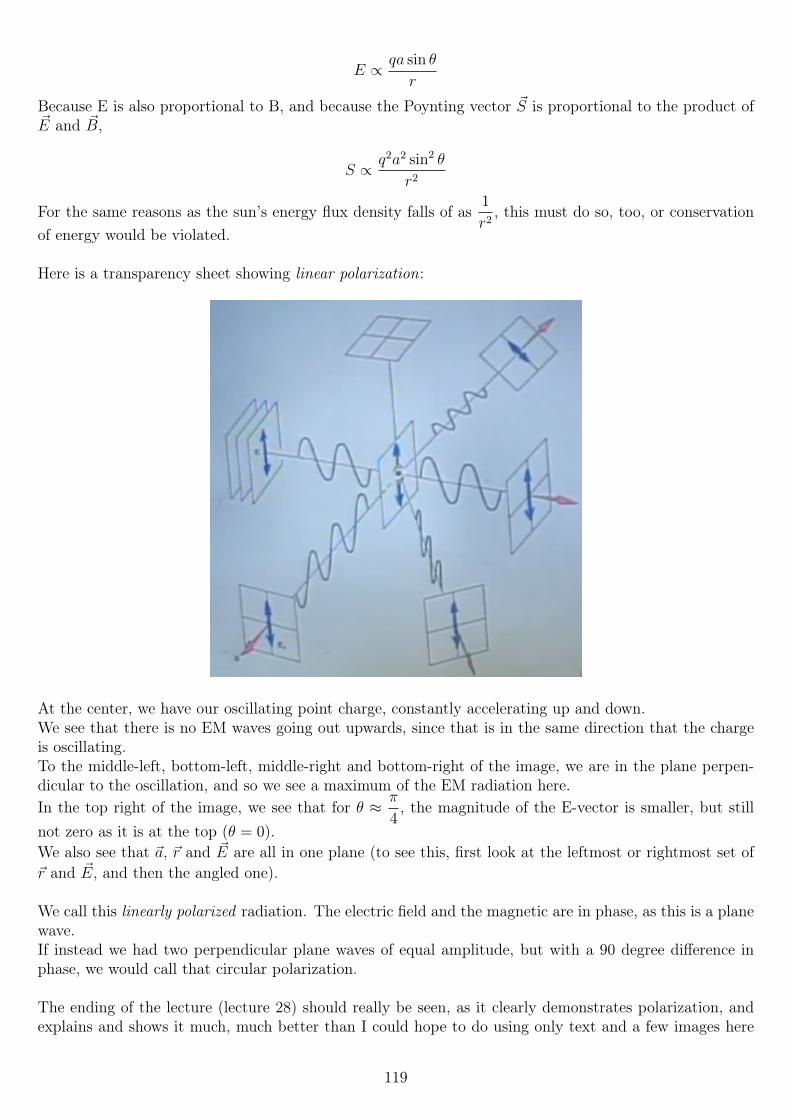
E ∝ qa sin θ
r
Because E is also proportional to B, and because the Poynting vector ~S is proportional to the product of~E and ~B,
S ∝ q2a2 sin2 θ
r2
For the same reasons as the sun’s energy flux density falls of as1
r2, this must do so, too, or conservation
of energy would be violated.
Here is a transparency sheet showing linear polarization:
At the center, we have our oscillating point charge, constantly accelerating up and down.We see that there is no EM waves going out upwards, since that is in the same direction that the chargeis oscillating.To the middle-left, bottom-left, middle-right and bottom-right of the image, we are in the plane perpen-dicular to the oscillation, and so we see a maximum of the EM radiation here.In the top right of the image, we see that for θ ≈ π
4, the magnitude of the E-vector is smaller, but still
not zero as it is at the top (θ = 0).We also see that ~a, ~r and ~E are all in one plane (to see this, first look at the leftmost or rightmost set of~r and ~E, and then the angled one).
We call this linearly polarized radiation. The electric field and the magnetic are in phase, as this is a planewave.If instead we had two perpendicular plane waves of equal amplitude, but with a 90 degree difference inphase, we would call that circular polarization.
The ending of the lecture (lecture 28) should really be seen, as it clearly demonstrates polarization, andexplains and shows it much, much better than I could hope to do using only text and a few images here
119
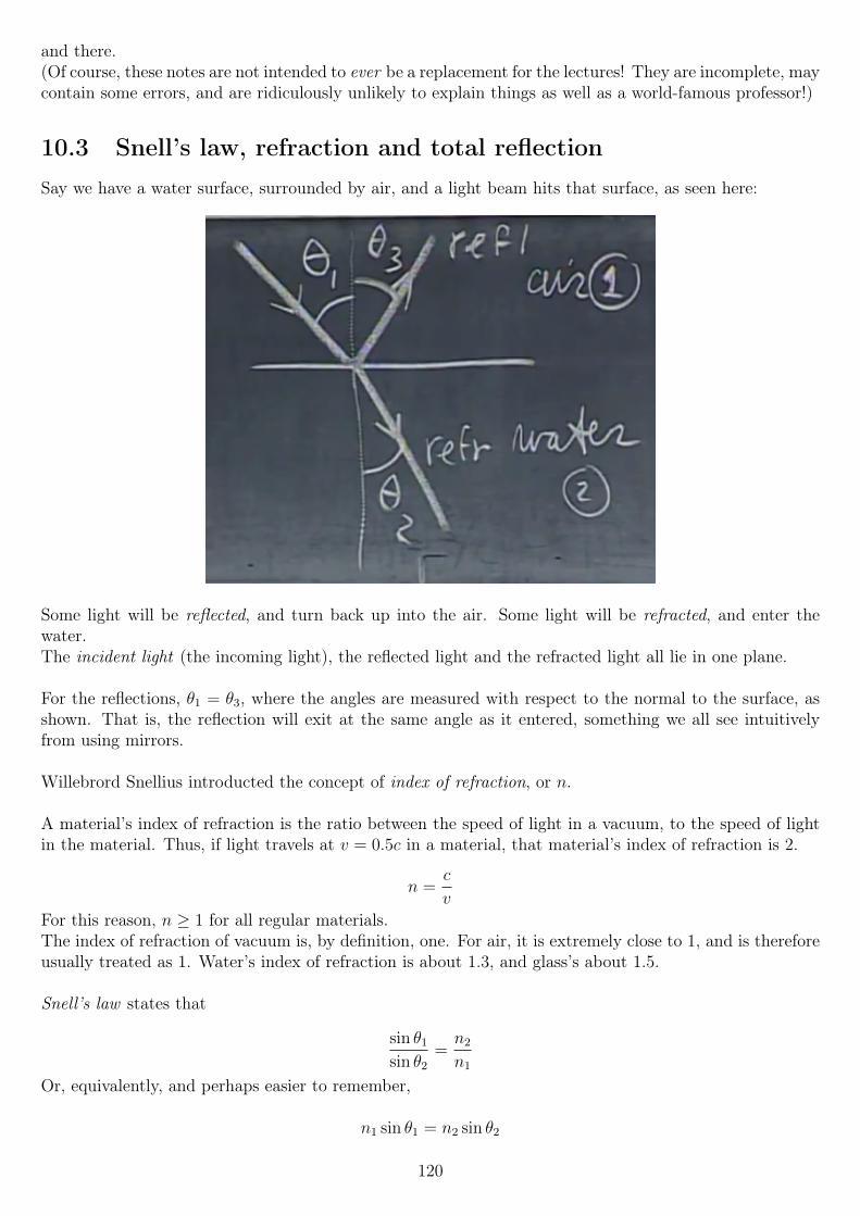
and there.(Of course, these notes are not intended to ever be a replacement for the lectures! They are incomplete, maycontain some errors, and are ridiculously unlikely to explain things as well as a world-famous professor!)
10.3 Snell’s law, refraction and total reflectionSay we have a water surface, surrounded by air, and a light beam hits that surface, as seen here:
Some light will be reflected, and turn back up into the air. Some light will be refracted, and enter thewater.The incident light (the incoming light), the reflected light and the refracted light all lie in one plane.
For the reflections, θ1 = θ3, where the angles are measured with respect to the normal to the surface, asshown. That is, the reflection will exit at the same angle as it entered, something we all see intuitivelyfrom using mirrors.
Willebrord Snellius introducted the concept of index of refraction, or n.
A material’s index of refraction is the ratio between the speed of light in a vacuum, to the speed of lightin the material. Thus, if light travels at v = 0.5c in a material, that material’s index of refraction is 2.
n =c
v
For this reason, n ≥ 1 for all regular materials.The index of refraction of vacuum is, by definition, one. For air, it is extremely close to 1, and is thereforeusually treated as 1. Water’s index of refraction is about 1.3, and glass’s about 1.5.
Snell’s law states that
sin θ1
sin θ2
=n2
n1
Or, equivalently, and perhaps easier to remember,
n1 sin θ1 = n2 sin θ2
120
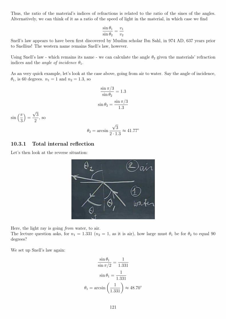
Thus, the ratio of the material’s indices of refractions is related to the ratio of the sines of the angles.Alternatively, we can think of it as a ratio of the speed of light in the material, in which case we find
sin θ1
sin θ2
=v1
v2
Snell’s law appears to have been first discovered by Muslim scholar Ibn Sahl, in 974 AD, 637 years priorto Snellius! The western name remains Snell’s law, however.
Using Snell’s law - which remains its name - we can calculate the angle θ2 given the materials’ refractionindices and the angle of incidence θ1.
As an very quick example, let’s look at the case above, going from air to water. Say the angle of incidence,θ1, is 60 degrees. n1 = 1 and n2 = 1.3, so
sin π/3
sin θ2
= 1.3
sin θ2 =sin π/3
1.3
sin(π
3
)=
√3
2, so
θ2 = arcsin
√3
2 · 1.3≈ 41.77
10.3.1 Total internal reflection
Let’s then look at the reverse situation:
Here, the light ray is going from water, to air.The lecture question asks, for n1 = 1.331 (n2 = 1, as it is air), how large must θ1 be for θ2 to equal 90degrees?
We set up Snell’s law again:
sin θ1
sin π/2=
1
1.331
sin θ1 =1
1.331
θ1 = arcsin
(1
1.331
)≈ 48.70
121
If the angle is greater than that, nature cannot deal with that refraction, and we get total reflection: allthe light is reflected, back into the water. Total reflection happens when the angle is greater than a criticalangle, that is
sin θcr =n2
n1
, if n1 > n2
So in this case, the critical angle is 48.7. If θ1 is greater than that, there would be no refraction, onlyreflection.
This principle (total internal reflection) has some interesting uses. Perhaps most significantly, it is theprinciple behind optical fiber, used (among other things) to create high-speed data links between comput-ers, cities, and even countries and continents.Such a fiber is made from a continuous piece of a form of glass or plastic. Light enters one end, runs ina straight line until it hits the outside, which is manufactured to have a lower refractive index than theinside. Therefore, as long as the angle is greater than the critical angle, total internal reflection causes thelight to keep bouncing away inside the fiber.This process is repeated over and over and over, until it reaches the end of the fiber.Materials research have made modern optical fiber extremely low-loss: a single unbroken piece of fiber canbe used to communicate over a distance of several hundred kilometers without any elecrtrical equipmentto strengthen the signal.
When a surface is smooth, parallel incoming light beams will reflect with equal angles (θ3 = θ1), and thusexit in parallel; we call this a specular reflection. Shining a laser pointer on a mirror is a great example ofa specular reflection.If the surface is rough, incoming light may be reflected in essentially random directions, and the lightwill not exit with the same angle, but exit in all sorts of directions. We call this a diffuse reflection; oneexample might be a laser pointer on a wooden table - or on most non-shiny surfaces, really.We will use the term “reflection” to mean specular reflection, as those are the kinds that can be easilycalculated, without knowing near-atomic-scale details of surfaces.
If a light ray enters a material, and then exits again, the new twice-refracted light ray will always beparallel with the incident ray. It will not be on the straight line, however, unless n1 = n2.
10.3.2 Frequency and wavelength in refraction
As light enters a medium, its frequency stays constant, but its wavelength changes. The relationship
v = λf
must always hold, but because v changes upon entering a different material, one of the other two mustalso decrease. The frequency cannot change, imagine a wave passing two observers inside two differentmaterial; point A is just before the boundary between the two materials, and point B just after. Ifthe wave’s frequency differs between the two points, that would imply that energy were piling up ordisappearing around the boundary.Thus, the wavelength has to change. The wavelengths follow the relationship
v1 = λ1f
v2 = λ2f
λ1
λ2
=v1
v2
=n2
n1
We saw previously that the speed of light is given by
122
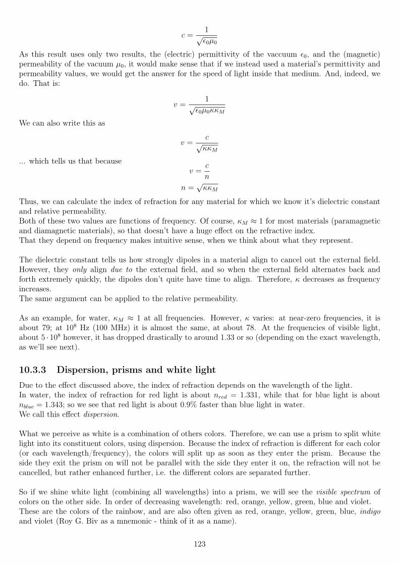
c =1
√ε0µ0
As this result uses only two results, the (electric) permittivity of the vaccuum ε0, and the (magnetic)permeability of the vacuum µ0, it would make sense that if we instead used a material’s permittivity andpermeability values, we would get the answer for the speed of light inside that medium. And, indeed, wedo. That is:
v =1
√ε0µ0κκM
We can also write this as
v =c
√κκM
... which tells us that becausev =
c
n
n =√κκM
Thus, we can calculate the index of refraction for any material for which we know it’s dielectric constantand relative permeability.Both of these two values are functions of frequency. Of course, κM ≈ 1 for most materials (paramagneticand diamagnetic materials), so that doesn’t have a huge effect on the refractive index.That they depend on frequency makes intuitive sense, when we think about what they represent.
The dielectric constant tells us how strongly dipoles in a material align to cancel out the external field.However, they only align due to the external field, and so when the external field alternates back andforth extremely quickly, the dipoles don’t quite have time to align. Therefore, κ decreases as frequencyincreases.The same argument can be applied to the relative permeability.
As an example, for water, κM ≈ 1 at all frequencies. However, κ varies: at near-zero frequencies, it isabout 79; at 108 Hz (100 MHz) it is almost the same, at about 78. At the frequencies of visible light,about 5 · 108 however, it has dropped drastically to around 1.33 or so (depending on the exact wavelength,as we’ll see next).
10.3.3 Dispersion, prisms and white light
Due to the effect discussed above, the index of refraction depends on the wavelength of the light.In water, the index of refraction for red light is about nred = 1.331, while that for blue light is aboutnblue = 1.343; so we see that red light is about 0.9% faster than blue light in water.We call this effect dispersion.
What we perceive as white is a combination of others colors. Therefore, we can use a prism to split whitelight into its constituent colors, using dispersion. Because the index of refraction is different for each color(or each wavelength/frequency), the colors will split up as soon as they enter the prism. Because theside they exit the prism on will not be parallel with the side they enter it on, the refraction will not becancelled, but rather enhanced further, i.e. the different colors are separated further.
So if we shine white light (combining all wavelengths) into a prism, we will see the visible spectrum ofcolors on the other side. In order of decreasing wavelength: red, orange, yellow, green, blue and violet.These are the colors of the rainbow, and are also often given as red, orange, yellow, green, blue, indigoand violet (Roy G. Biv as a mnemonic - think of it as a name).
123
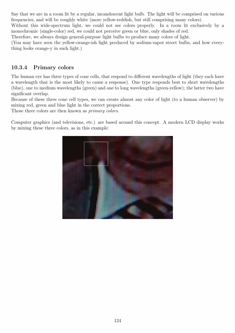
Say that we are in a room lit by a regular, incandescent light bulb. The light will be comprised on variousfrequencies, and will be roughly white (more yellow-reddish, but still comprising many colors).Without this wide-spectrum light, we could not see colors properly. In a room lit exclusively by amonochromic (single-color) red, we could not perceive green or blue, only shades of red.Therefore, we always design general-purpose light bulbs to produce many colors of light.(You may have seen the yellow-orange-ish light produced by sodium-vapor street bulbs, and how every-thing looks orange-y in such light.)
10.3.4 Primary colors
The human eye has three types of cone cells, that respond to different wavelengths of light (they each havea wavelength that is the most likely to cause a response). One type responds best to short wavelengths(blue), one to medium wavelengths (green) and one to long wavelengths (green-yellow); the latter two havesignificant overlap.Because of these three cone cell types, we can create almost any color of light (to a human observer) bymixing red, green and blue light in the correct proportions.Those three colors are then known as primary colors.
Computer graphics (and televisions, etc.) are based around this concept. A modern LCD display worksby mixing these three colors, as in this example:
124
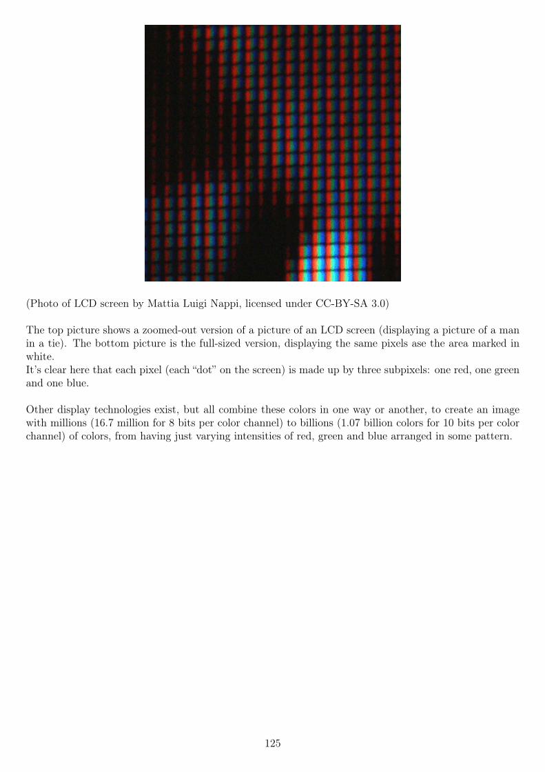
(Photo of LCD screen by Mattia Luigi Nappi, licensed under CC-BY-SA 3.0)
The top picture shows a zoomed-out version of a picture of an LCD screen (displaying a picture of a manin a tie). The bottom picture is the full-sized version, displaying the same pixels ase the area marked inwhite.It’s clear here that each pixel (each “dot” on the screen) is made up by three subpixels: one red, one greenand one blue.
Other display technologies exist, but all combine these colors in one way or another, to create an imagewith millions (16.7 million for 8 bits per color channel) to billions (1.07 billion colors for 10 bits per colorchannel) of colors, from having just varying intensities of red, green and blue arranged in some pattern.
125
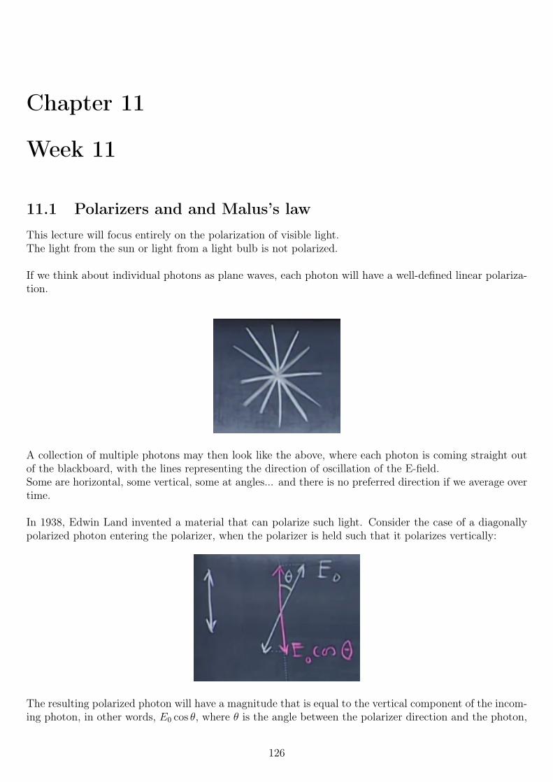
Chapter 11
Week 11
11.1 Polarizers and and Malus’s lawThis lecture will focus entirely on the polarization of visible light.The light from the sun or light from a light bulb is not polarized.
If we think about individual photons as plane waves, each photon will have a well-defined linear polariza-tion.
A collection of multiple photons may then look like the above, where each photon is coming straight outof the blackboard, with the lines representing the direction of oscillation of the E-field.Some are horizontal, some vertical, some at angles... and there is no preferred direction if we average overtime.
In 1938, Edwin Land invented a material that can polarize such light. Consider the case of a diagonallypolarized photon entering the polarizer, when the polarizer is held such that it polarizes vertically:
The resulting polarized photon will have a magnitude that is equal to the vertical component of the incom-ing photon, in other words, E0 cos θ, where θ is the angle between the polarizer direction and the photon,
126
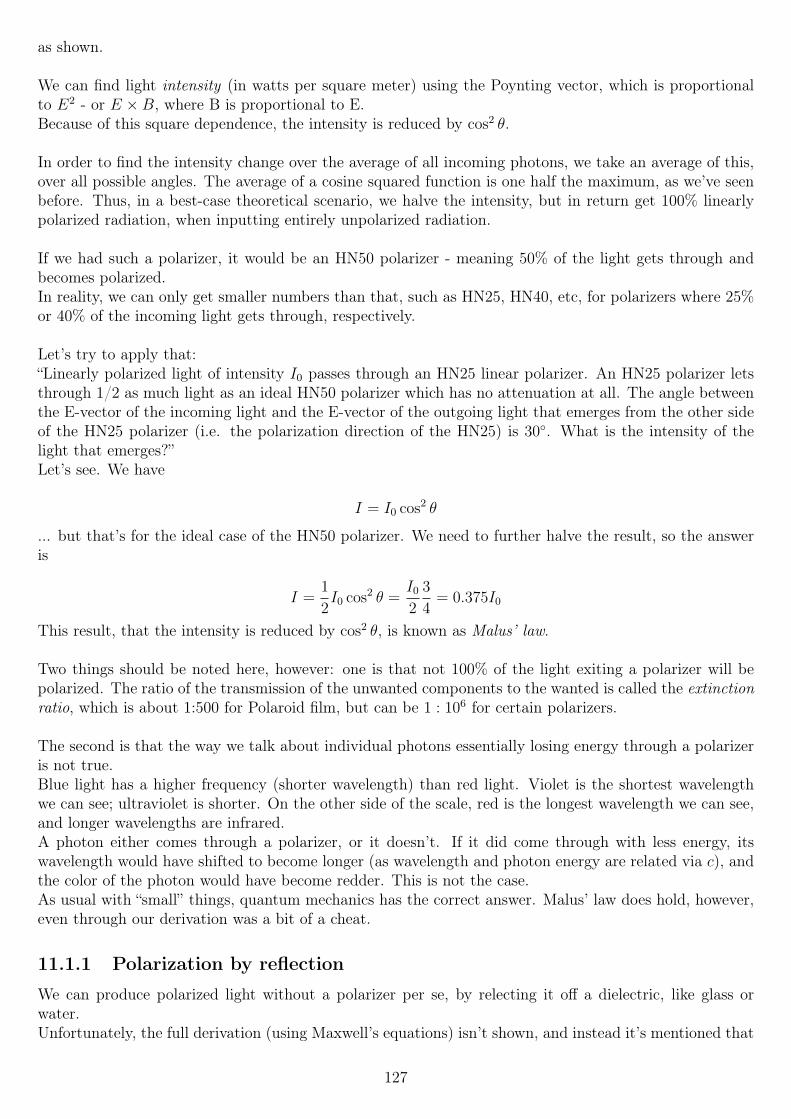
as shown.
We can find light intensity (in watts per square meter) using the Poynting vector, which is proportionalto E2 - or E ×B, where B is proportional to E.Because of this square dependence, the intensity is reduced by cos2 θ.
In order to find the intensity change over the average of all incoming photons, we take an average of this,over all possible angles. The average of a cosine squared function is one half the maximum, as we’ve seenbefore. Thus, in a best-case theoretical scenario, we halve the intensity, but in return get 100% linearlypolarized radiation, when inputting entirely unpolarized radiation.
If we had such a polarizer, it would be an HN50 polarizer - meaning 50% of the light gets through andbecomes polarized.In reality, we can only get smaller numbers than that, such as HN25, HN40, etc, for polarizers where 25%or 40% of the incoming light gets through, respectively.
Let’s try to apply that:“Linearly polarized light of intensity I0 passes through an HN25 linear polarizer. An HN25 polarizer letsthrough 1/2 as much light as an ideal HN50 polarizer which has no attenuation at all. The angle betweenthe E-vector of the incoming light and the E-vector of the outgoing light that emerges from the other sideof the HN25 polarizer (i.e. the polarization direction of the HN25) is 30. What is the intensity of thelight that emerges?”Let’s see. We have
I = I0 cos2 θ
... but that’s for the ideal case of the HN50 polarizer. We need to further halve the result, so the answeris
I =1
2I0 cos2 θ =
I0
2
3
4= 0.375I0
This result, that the intensity is reduced by cos2 θ, is known as Malus’ law.
Two things should be noted here, however: one is that not 100% of the light exiting a polarizer will bepolarized. The ratio of the transmission of the unwanted components to the wanted is called the extinctionratio, which is about 1:500 for Polaroid film, but can be 1 : 106 for certain polarizers.
The second is that the way we talk about individual photons essentially losing energy through a polarizeris not true.Blue light has a higher frequency (shorter wavelength) than red light. Violet is the shortest wavelengthwe can see; ultraviolet is shorter. On the other side of the scale, red is the longest wavelength we can see,and longer wavelengths are infrared.A photon either comes through a polarizer, or it doesn’t. If it did come through with less energy, itswavelength would have shifted to become longer (as wavelength and photon energy are related via c), andthe color of the photon would have become redder. This is not the case.As usual with “small” things, quantum mechanics has the correct answer. Malus’ law does hold, however,even through our derivation was a bit of a cheat.
11.1.1 Polarization by reflection
We can produce polarized light without a polarizer per se, by relecting it off a dielectric, like glass orwater.Unfortunately, the full derivation (using Maxwell’s equations) isn’t shown, and instead it’s mentioned that
127
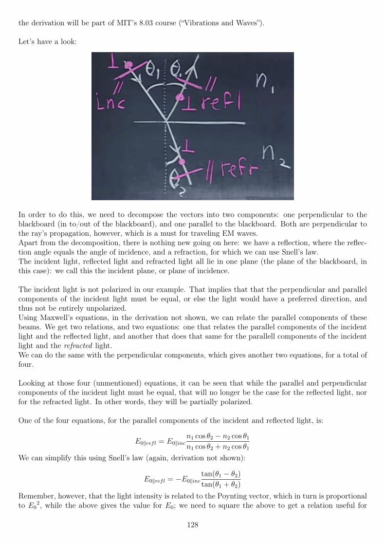
the derivation will be part of MIT’s 8.03 course (“Vibrations and Waves”).
Let’s have a look:
In order to do this, we need to decompose the vectors into two components: one perpendicular to theblackboard (in to/out of the blackboard), and one parallel to the blackboard. Both are perpendicular tothe ray’s propagation, however, which is a must for traveling EM waves.Apart from the decomposition, there is nothing new going on here: we have a reflection, where the reflec-tion angle equals the angle of incidence, and a refraction, for which we can use Snell’s law.The incident light, reflected light and refracted light all lie in one plane (the plane of the blackboard, inthis case): we call this the incident plane, or plane of incidence.
The incident light is not polarized in our example. That implies that that the perpendicular and parallelcomponents of the incident light must be equal, or else the light would have a preferred direction, andthus not be entirely unpolarized.Using Maxwell’s equations, in the derivation not shown, we can relate the parallel components of thesebeams. We get two relations, and two equations: one that relates the parallel components of the incidentlight and the reflected light, and another that does that same for the parallell components of the incidentlight and the refracted light.We can do the same with the perpendicular components, which gives another two equations, for a total offour.
Looking at those four (unmentioned) equations, it can be seen that while the parallel and perpendicularcomponents of the incident light must be equal, that will no longer be the case for the reflected light, norfor the refracted light. In other words, they will be partially polarized.
One of the four equations, for the parallel components of the incident and reflected light, is:
E0‖refl = E0‖incn1 cos θ2 − n2 cos θ1
n1 cos θ2 + n2 cos θ1
We can simplify this using Snell’s law (again, derivation not shown):
E0‖refl = −E0‖inctan(θ1 − θ2)
tan(θ1 + θ2)
Remember, however, that the light intensity is related to the Poynting vector, which in turn is proportionalto E0
2, while the above gives the value for E0; we need to square the above to get a relation useful for
128
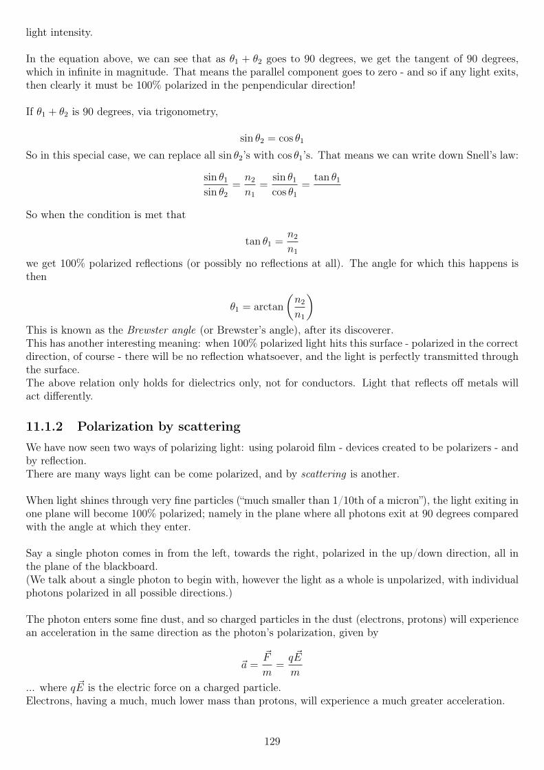
light intensity.
In the equation above, we can see that as θ1 + θ2 goes to 90 degrees, we get the tangent of 90 degrees,which in infinite in magnitude. That means the parallel component goes to zero - and so if any light exits,then clearly it must be 100% polarized in the penpendicular direction!
If θ1 + θ2 is 90 degrees, via trigonometry,
sin θ2 = cos θ1
So in this special case, we can replace all sin θ2’s with cos θ1’s. That means we can write down Snell’s law:
sin θ1
sin θ2
=n2
n1
=sin θ1
cos θ1
=tan θ1
So when the condition is met that
tan θ1 =n2
n1
we get 100% polarized reflections (or possibly no reflections at all). The angle for which this happens isthen
θ1 = arctan
(n2
n1
)This is known as the Brewster angle (or Brewster’s angle), after its discoverer.This has another interesting meaning: when 100% polarized light hits this surface - polarized in the correctdirection, of course - there will be no reflection whatsoever, and the light is perfectly transmitted throughthe surface.The above relation only holds for dielectrics only, not for conductors. Light that reflects off metals willact differently.
11.1.2 Polarization by scattering
We have now seen two ways of polarizing light: using polaroid film - devices created to be polarizers - andby reflection.There are many ways light can be come polarized, and by scattering is another.
When light shines through very fine particles (“much smaller than 1/10th of a micron”), the light exiting inone plane will become 100% polarized; namely in the plane where all photons exit at 90 degrees comparedwith the angle at which they enter.
Say a single photon comes in from the left, towards the right, polarized in the up/down direction, all inthe plane of the blackboard.(We talk about a single photon to begin with, however the light as a whole is unpolarized, with individualphotons polarized in all possible directions.)
The photon enters some fine dust, and so charged particles in the dust (electrons, protons) will experiencean acceleration in the same direction as the photon’s polarization, given by
~a =~F
m=q ~E
m
... where q ~E is the electric force on a charged particle.Electrons, having a much, much lower mass than protons, will experience a much greater acceleration.
129
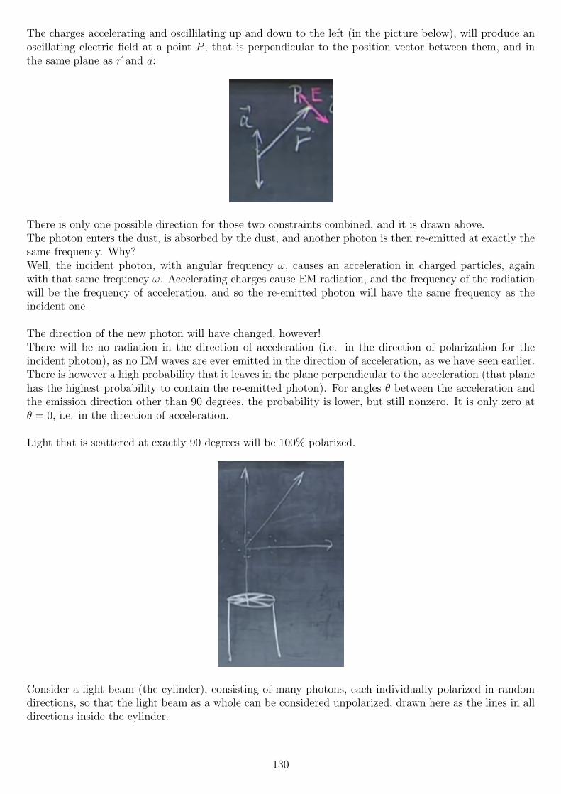
The charges accelerating and oscillilating up and down to the left (in the picture below), will produce anoscillating electric field at a point P , that is perpendicular to the position vector between them, and inthe same plane as ~r and ~a:
There is only one possible direction for those two constraints combined, and it is drawn above.The photon enters the dust, is absorbed by the dust, and another photon is then re-emitted at exactly thesame frequency. Why?Well, the incident photon, with angular frequency ω, causes an acceleration in charged particles, againwith that same frequency ω. Accelerating charges cause EM radiation, and the frequency of the radiationwill be the frequency of acceleration, and so the re-emitted photon will have the same frequency as theincident one.
The direction of the new photon will have changed, however!There will be no radiation in the direction of acceleration (i.e. in the direction of polarization for theincident photon), as no EM waves are ever emitted in the direction of acceleration, as we have seen earlier.There is however a high probability that it leaves in the plane perpendicular to the acceleration (that planehas the highest probability to contain the re-emitted photon). For angles θ between the acceleration andthe emission direction other than 90 degrees, the probability is lower, but still nonzero. It is only zero atθ = 0, i.e. in the direction of acceleration.
Light that is scattered at exactly 90 degrees will be 100% polarized.
Consider a light beam (the cylinder), consisting of many photons, each individually polarized in randomdirections, so that the light beam as a whole can be considered unpolarized, drawn here as the lines in alldirections inside the cylinder.
130
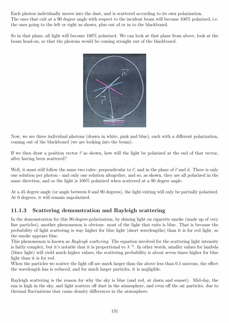
Each photon individually moves into the dust, and is scattered according to its own polarization.The ones that exit at a 90 degree angle with respect to the incident beam will become 100% polarized, i.e.the ones going to the left or right as shown, plus out of or in to the blackboard.
So in that plane, all light will become 100% polarized. We can look at that plane from above, look at thebeam head-on, so that the photons would be coming straight out of the blackboard.
Now, we see three individual photons (drawn in white, pink and blue), each with a different polarization,coming out of the blackboard (we are looking into the beam).
If we then draw a position vector ~r as shown, how will the light be polarized at the end of that vector,after having been scattered?
Well, it must still follow the same two rules: perpendicular to ~r, and in the plane of ~r and ~a. There is onlyone solution per photon - and only one solution altogether, and so, as shown, they are all polarized in thesame direction, and so the light is 100% polarized when scattered at a 90 degree angle.
At a 45 degree angle (or angle between 0 and 90 degrees), the light exiting will only be partially polarized.At 0 degrees, it will remain unpolarized.
11.1.3 Scattering demonstration and Rayleigh scattering
In the demonstration for this 90-degree-polarization, by shining light on cigarette smoke (made up of veryfine particles), another phenomenon is obvious: most of the light that exits is blue. That is because theprobability of light scattering is way higher for blue light (short wavelengths) than it is for red light, sothe smoke appears blue.This phenomenon is known as Rayleigh scattering. The equation involved for the scattering light intensityis fairly complex, but it’s notable that it is proportional to λ−4. In other words, smaller values for lambda(bluer light) will yield much higher values; the scattering probability is about seven times higher for bluelight than it is for red.When the particles we scatter the light off are much larger than the above less than 0.1 microns, the effectthe wavelength has is reduced, and for much larger particles, it is negligible.
Rayleigh scattering is the reason for why the sky is blue (and red, at dawn and sunset). Mid-day, thesun is high in the sky, and light scatters off dust in the atmosphere, and even off the air particles, due tothermal fluctuations that cause density differences in the atmosphere.
131
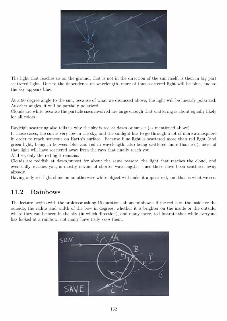
The light that reaches us on the ground, that is not in the direction of the sun itself, is then in big partscattered light. Due to the dependence on wavelength, more of that scattered light will be blue, and sothe sky appears blue.
At a 90 degree angle to the sun, because of what we discussed above, the light will be linearly polarized.At other angles, it will be partially polarized.Clouds are white because the particle sizes involved are large enough that scattering is about equally likelyfor all colors.
Rayleigh scattering also tells us why the sky is red at dawn or sunset (as mentioned above).It those cases, the sun is very low in the sky, and the sunlight has to go through a lot of more atmospherein order to reach someone on Earth’s surface. Because blue light is scattered more than red light (andgreen light, being in between blue and red in wavelength, also being scattered more than red), most ofthat light will have scattered away from the rays that finally reach you.And so, only the red light remains.Clouds are reddish at dawn/sunset for about the same reason: the light that reaches the cloud, andeventually reaches you, is mostly devoid of shorter wavelengths, since those have been scattered awayalready.Having only red light shine on an otherwise white object will make it appear red, and that is what we see.
11.2 RainbowsThe lecture begins with the professor asking 15 questions about rainbows: if the red is on the inside or theoutside, the radius and width of the bow in degrees, whether it is brighter on the inside or the outside,where they can be seen in the sky (in which direction), and many more, to illustrate that while everyonehas looked at a rainbow, not many have truly seen them.
132
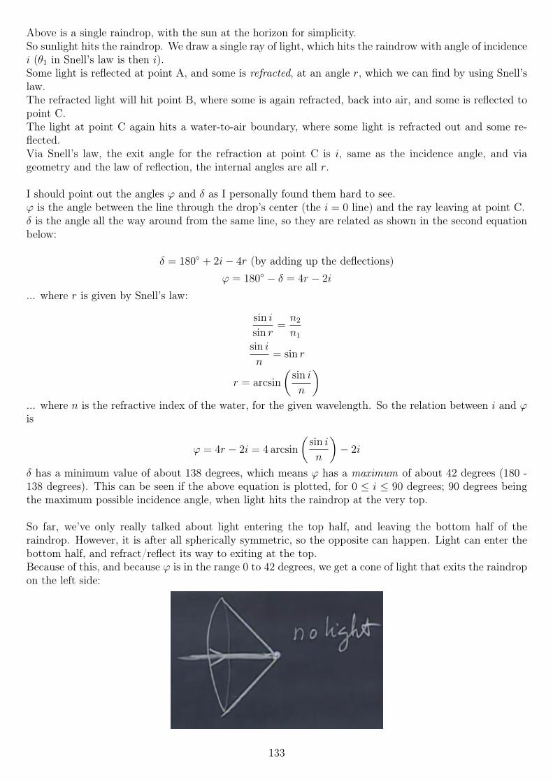
Above is a single raindrop, with the sun at the horizon for simplicity.So sunlight hits the raindrop. We draw a single ray of light, which hits the raindrow with angle of incidencei (θ1 in Snell’s law is then i).Some light is reflected at point A, and some is refracted, at an angle r, which we can find by using Snell’slaw.The refracted light will hit point B, where some is again refracted, back into air, and some is reflected topoint C.The light at point C again hits a water-to-air boundary, where some light is refracted out and some re-flected.Via Snell’s law, the exit angle for the refraction at point C is i, same as the incidence angle, and viageometry and the law of reflection, the internal angles are all r.
I should point out the angles ϕ and δ as I personally found them hard to see.ϕ is the angle between the line through the drop’s center (the i = 0 line) and the ray leaving at point C.δ is the angle all the way around from the same line, so they are related as shown in the second equationbelow:
δ = 180 + 2i− 4r (by adding up the deflections)ϕ = 180 − δ = 4r − 2i
... where r is given by Snell’s law:
sin i
sin r=n2
n1
sin i
n= sin r
r = arcsin
(sin i
n
)... where n is the refractive index of the water, for the given wavelength. So the relation between i and ϕis
ϕ = 4r − 2i = 4 arcsin
(sin i
n
)− 2i
δ has a minimum value of about 138 degrees, which means ϕ has a maximum of about 42 degrees (180 -138 degrees). This can be seen if the above equation is plotted, for 0 ≤ i ≤ 90 degrees; 90 degrees beingthe maximum possible incidence angle, when light hits the raindrop at the very top.
So far, we’ve only really talked about light entering the top half, and leaving the bottom half of theraindrop. However, it is after all spherically symmetric, so the opposite can happen. Light can enter thebottom half, and refract/reflect its way to exiting at the top.Because of this, and because ϕ is in the range 0 to 42 degrees, we get a cone of light that exits the raindropon the left side:
133
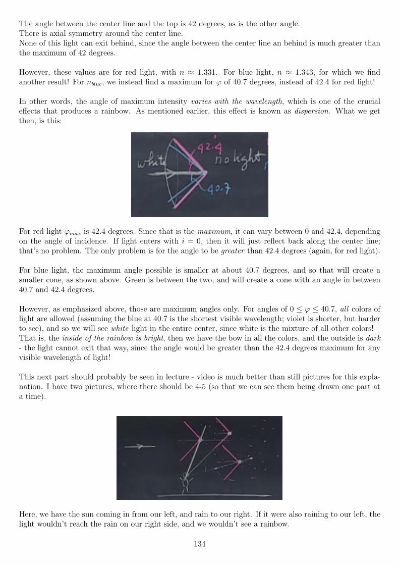
The angle between the center line and the top is 42 degrees, as is the other angle.There is axial symmetry around the center line.None of this light can exit behind, since the angle between the center line an behind is much greater thanthe maximum of 42 degrees.
However, these values are for red light, with n ≈ 1.331. For blue light, n ≈ 1.343, for which we findanother result! For nblue, we instead find a maximum for ϕ of 40.7 degrees, instead of 42.4 for red light!
In other words, the angle of maximum intensity varies with the wavelength, which is one of the crucialeffects that produces a rainbow. As mentioned earlier, this effect is known as dispersion. What we getthen, is this:
For red light ϕmax is 42.4 degrees. Since that is the maximum, it can vary between 0 and 42.4, dependingon the angle of incidence. If light enters with i = 0, then it will just reflect back along the center line;that’s no problem. The only problem is for the angle to be greater than 42.4 degrees (again, for red light).
For blue light, the maximum angle possible is smaller at about 40.7 degrees, and so that will create asmaller cone, as shown above. Green is between the two, and will create a cone with an angle in between40.7 and 42.4 degrees.
However, as emphasized above, those are maximum angles only. For angles of 0 ≤ ϕ ≤ 40.7, all colors oflight are allowed (assuming the blue at 40.7 is the shortest visible wavelength; violet is shorter, but harderto see), and so we will see white light in the entire center, since white is the mixture of all other colors!That is, the inside of the rainbow is bright, then we have the bow in all the colors, and the outside is dark- the light cannot exit that way, since the angle would be greater than the 42.4 degrees maximum for anyvisible wavelength of light!
This next part should probably be seen in lecture - video is much better than still pictures for this expla-nation. I have two pictures, where there should be 4-5 (so that we can see them being drawn one part ata time).
Here, we have the sun coming in from our left, and rain to our right. If it were also raining to our left, thelight wouldn’t reach the rain on our right side, and we wouldn’t see a rainbow.
134
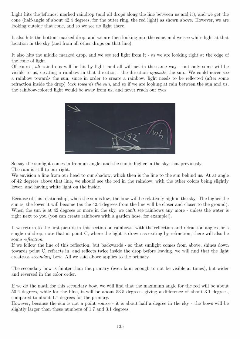
Light hits the leftmost marked raindrop (and all drops along the line between us and it), and we get thecone (half-angle of about 42.4 degrees, for the outer ring, the red light) as shown above. However, we arelooking outside that cone, and so we see no light there.
It also hits the bottom marked drop, and we are then looking into the cone, and we see white light at thatlocation in the sky (and from all other drops on that line).
It also hits the middle marked drop, and we see red light from it - as we are looking right at the edge ofthe cone of light.Of course, all raindrops will be hit by light, and all will act in the same way - but only some will bevisible to us, creating a rainbow in that direction - the direction opposite the sun. We could never seea rainbow towards the sun, since in order to create a rainbow, light needs to be reflected (after somerefraction inside the drop) back towards the sun, and so if we are looking at rain between the sun and us,the rainbow-colored light would be away from us, and never reach our eyes.
So say the sunlight comes in from an angle, and the sun is higher in the sky that previously.The rain is still to our right.We envision a line from our head to our shadow, which then is the line to the sun behind us. At at angleof 42 degrees above that line, we should see the red in the raindow, with the other colors being slightlylower, and having white light on the inside.
Because of this relationship, when the sun is low, the bow will be relatively high in the sky. The higher thesun is, the lower it will become (as the 42.4 degrees from the line will be closer and closer to the ground).When the sun is at 42 degrees or more in the sky, we can’t see rainbows any more - unless the water isright next to you (you can create rainbows with a garden hose, for example!).
If we return to the first picture in this section on rainbows, with the reflection and refraction angles for asingle raindrop, note that at point C, where the light is drawn as exiting by refraction, there will also besome reflection.If we follow the line of this reflection, but backwards - so that sunlight comes from above, shines downtowards point C, refracts in, and reflects twice inside the drop before leaving, we will find that the lightcreates a secondary bow. All we said above applies to the primary.
The secondary bow is fainter than the primary (even faint enough to not be visible at times), but widerand reversed in the color order.
If we do the math for this secondary bow, we will find that the maximum angle for the red will be about50.4 degrees, while for the blue, it will be about 53.5 degrees, giving a difference of about 3.1 degrees,compared to about 1.7 degrees for the primary.However, because the sun is not a point source - it is about half a degree in the sky - the bows will beslightly larger than these numbers of 1.7 and 3.1 degrees.
135
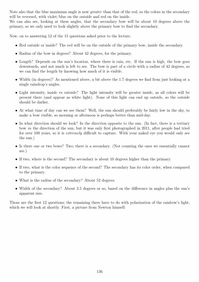
Note also that the blue maximum angle is now greater than that of the red, so the colors in the secondarywill be reversed, with violet/blue on the outside and red on the inside.We can also see, looking at these angles, that the secondary bow will be about 10 degrees above theprimary, so we only need to look slightly above the primary bow to find the secondary.
Now, on to answering 12 of the 15 questions asked prior to the lecture.
• Red outside or inside? The red will be on the outside of the primary bow, inside the secondary.
• Radius of the bow in degrees? About 42 degrees, for the primary.
• Length? Depends on the sun’s location, where there is rain, etc. If the sun is high, the bow goesdownwards, and not much is left to see. The bow is part of a circle with a radius of 42 degrees, sowe can find the length by knowing how much of it is visible.
• Width (in degrees)? As mentioned above, a bit above the 1.7 degrees we find from just looking at asingle raindrop’s angles.
• Light intensity, inside vs outside? The light intensity will be greater inside, as all colors will bepresent there (and appear as white light). None of this light can end up outside, so the outsideshould be darker.
• At what time of day can we see them? Well, the sun should preferably be fairly low in the sky, tomake a bow visible, so morning or afternoon is perhaps better than mid-day.
• In what direction should we look? In the direction opposite to the sun. (In fact, there is a tertiarybow in the direction of the sun, but it was only first photographed in 2011, after people had triedfor over 100 years, so it is extremely difficult to capture. With your naked eye you would only seethe sun.)
• Is there one or two bows? Two; there is a secondary. (Not counting the ones we essentially cannotsee.)
• If two, where is the second? The secondary is about 10 degrees higher than the primary.
• If two, what is the color sequence of the second? The secondary has its color order, when comparedto the primary.
• What is the radius of the secondary? About 52 degrees.
• Width of the secondary? About 3.5 degrees or so, based on the difference in angles plus the sun’sapparent size.
Those are the first 12 questions; the remaining three have to do with polarization of the rainbow’s light,which we will look at shortly. First, a picture from Newton himself:
136
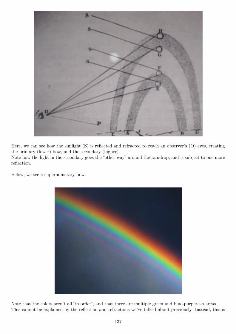
Here, we can see how the sunlight (S) is reflected and refracted to reach an observer’s (O) eyes, creatingthe primary (lower) bow, and the secondary (higher).Note how the light in the secondary goes the “other way” around the raindrop, and is subject to one morereflection.
Below, we see a supernumerary bow.
Note that the colors aren’t all “in order”, and that there are multiple green and blue-purple-ish areas.This cannot be explained by the reflection and refractions we’ve talked about previously. Instead, this is
137
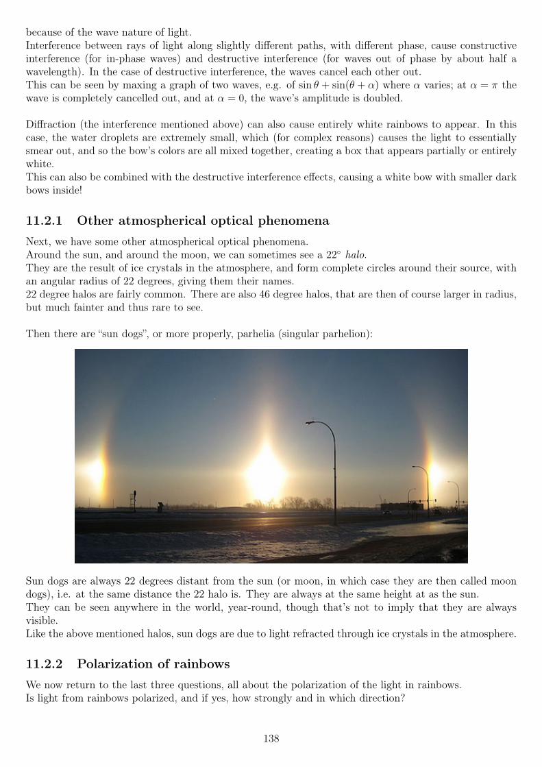
because of the wave nature of light.Interference between rays of light along slightly different paths, with different phase, cause constructiveinterference (for in-phase waves) and destructive interference (for waves out of phase by about half awavelength). In the case of destructive interference, the waves cancel each other out.This can be seen by maxing a graph of two waves, e.g. of sin θ + sin(θ + α) where α varies; at α = π thewave is completely cancelled out, and at α = 0, the wave’s amplitude is doubled.
Diffraction (the interference mentioned above) can also cause entirely white rainbows to appear. In thiscase, the water droplets are extremely small, which (for complex reasons) causes the light to essentiallysmear out, and so the bow’s colors are all mixed together, creating a box that appears partially or entirelywhite.This can also be combined with the destructive interference effects, causing a white bow with smaller darkbows inside!
11.2.1 Other atmospherical optical phenomena
Next, we have some other atmospherical optical phenomena.Around the sun, and around the moon, we can sometimes see a 22 halo.They are the result of ice crystals in the atmosphere, and form complete circles around their source, withan angular radius of 22 degrees, giving them their names.22 degree halos are fairly common. There are also 46 degree halos, that are then of course larger in radius,but much fainter and thus rare to see.
Then there are “sun dogs”, or more properly, parhelia (singular parhelion):
Sun dogs are always 22 degrees distant from the sun (or moon, in which case they are then called moondogs), i.e. at the same distance the 22 halo is. They are always at the same height at as the sun.They can be seen anywhere in the world, year-round, though that’s not to imply that they are alwaysvisible.Like the above mentioned halos, sun dogs are due to light refracted through ice crystals in the atmosphere.
11.2.2 Polarization of rainbows
We now return to the last three questions, all about the polarization of the light in rainbows.Is light from rainbows polarized, and if yes, how strongly and in which direction?
138
The answer is yes, and very strongly; as for the direction, the light will be polarized “along” the bow: atthe leftmost part, the polarization will be up/down, curving along the bow, being horizontal at the bow’stop, and then again turn vertical at the very end.Looking again at the diagram of the single raindrop, we know that the actual bow shows up when ϕ ≈ 42degrees, which happens when the angle of incidence is about 60 degrees.The angle of refraction r is related to i via Snell’s law, as the light is refracted:
r = arcsin
(sin i
n2
)So for n2 ≈ 1.333 in water, and i of 60 degrees, r ≈ 40.5 degrees.At that point, B, where light is reflected back towards the front (left side) of the raindrop, the Brewsterangle is given by
θBr = arctann2
n1
... where n2 is the refractive index of the medium the light would be going to (the air, n2 = 1), and n1
the refractive index of the water, n1 ≈ 1.333. With those values, we find θBr ≈ 37.88 degrees, which is ofcourse very close to the 40.5 or so degree angle of the light coming there.Because light would be 100% polarized at the Brewster angle, the light will be not 100%, but very stronglypolarized.
11.3 Review for Exam 3There was just about nothing reviewed that had not been covered previously, as expected, so I did nottake any notes watching this lecture.
139
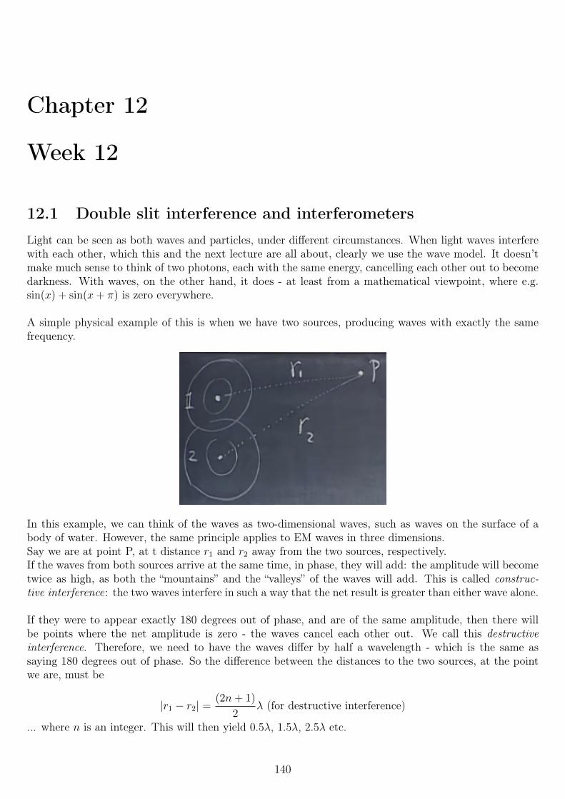
Chapter 12
Week 12
12.1 Double slit interference and interferometersLight can be seen as both waves and particles, under different circumstances. When light waves interferewith each other, which this and the next lecture are all about, clearly we use the wave model. It doesn’tmake much sense to think of two photons, each with the same energy, cancelling each other out to becomedarkness. With waves, on the other hand, it does - at least from a mathematical viewpoint, where e.g.sin(x) + sin(x+ π) is zero everywhere.
A simple physical example of this is when we have two sources, producing waves with exactly the samefrequency.
In this example, we can think of the waves as two-dimensional waves, such as waves on the surface of abody of water. However, the same principle applies to EM waves in three dimensions.Say we are at point P, at t distance r1 and r2 away from the two sources, respectively.If the waves from both sources arrive at the same time, in phase, they will add: the amplitude will becometwice as high, as both the “mountains” and the “valleys” of the waves will add. This is called construc-tive interference: the two waves interfere in such a way that the net result is greater than either wave alone.
If they were to appear exactly 180 degrees out of phase, and are of the same amplitude, then there willbe points where the net amplitude is zero - the waves cancel each other out. We call this destructiveinterference. Therefore, we need to have the waves differ by half a wavelength - which is the same assaying 180 degrees out of phase. So the difference between the distances to the two sources, at the pointwe are, must be
|r1 − r2| =(2n+ 1)
2λ (for destructive interference)
... where n is an integer. This will then yield 0.5λ, 1.5λ, 2.5λ etc.
140
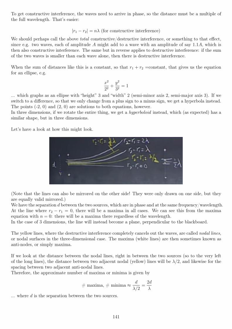
To get constructive interference, the waves need to arrive in phase, so the distance must be a multiple ofthe full wavelength. That’s easier:
|r1 − r2| = nλ (for constructive interference)
We should perhaps call the above total constructive/destructive interference, or something to that effect,since e.g. two waves, each of amplitude A might add to a wave with an amplitude of say 1.1A, which isthen also constructive interference. The same but in reverse applies to destructive interference: if the sumof the two waves is smaller than each wave alone, then there is destructive interference.
When the sum of distances like this is a constant, so that r1 + r2 =constant, that gives us the equationfor an ellipse, e.g.
x2
22+y2
32= 1
... which graphs as an ellipse with “height” 3 and “width” 2 (semi-minor axis 2, semi-major axis 3). If weswitch to a difference, so that we only change from a plus sign to a minus sign, we get a hyperbola instead.The points (-2, 0) and (2, 0) are solutions to both equations, however.In three dimensions, if we rotate the entire thing, we get a hyperboloid instead, which (as expected) has asimilar shape, but in three dimensions.
Let’s have a look at how this might look.
(Note that the lines can also be mirrored on the other side! They were only drawn on one side, but theyare equally valid mirrored.)We have the separation d between the two sources, which are in phase and at the same frequency/wavelength.At the line where r2 − r1 = 0, there will be a maxima in all cases. We can see this from the maximaequation with n = 0: there will be a maxima there regardless of the wavelength.In the case of 3 dimensions, the line will instead become a plane, perpendicular to the blackboard.
The yellow lines, where the destructive interference completely cancels out the waves, are called nodal lines,or nodal surfaces in the three-dimensional case. The maxima (white lines) are then sometimes known asanti-nodes, or simply maxima.
If we look at the distance between the nodal lines, right in between the two sources (so to the very leftof the long lines), the distance between two adjacent nodal (yellow) lines will be λ/2, and likewise for thespacing between two adjacent anti-nodal lines.Therefore, the approximate number of maxima or minima is given by
# maxima, # minima ≈ d
λ/2=
2d
λ
... where d is the separation between the two sources.
141
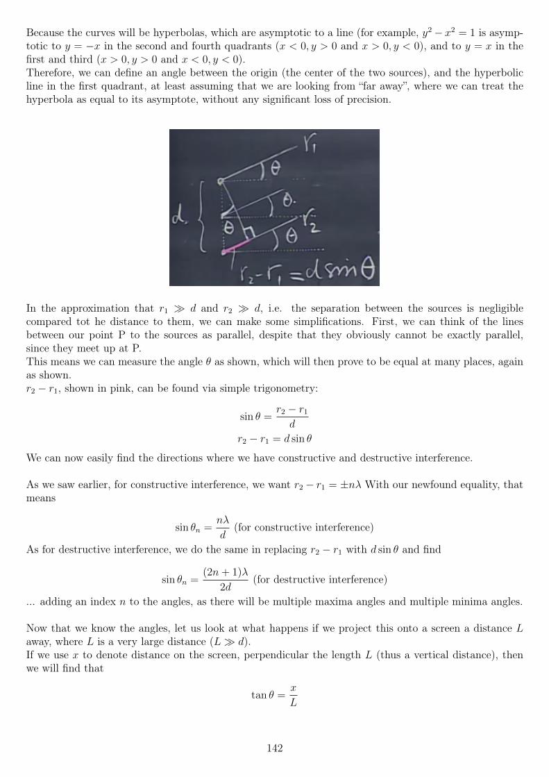
Because the curves will be hyperbolas, which are asymptotic to a line (for example, y2− x2 = 1 is asymp-totic to y = −x in the second and fourth quadrants (x < 0, y > 0 and x > 0, y < 0), and to y = x in thefirst and third (x > 0, y > 0 and x < 0, y < 0).Therefore, we can define an angle between the origin (the center of the two sources), and the hyperbolicline in the first quadrant, at least assuming that we are looking from “far away”, where we can treat thehyperbola as equal to its asymptote, without any significant loss of precision.
In the approximation that r1 d and r2 d, i.e. the separation between the sources is negligiblecompared tot he distance to them, we can make some simplifications. First, we can think of the linesbetween our point P to the sources as parallel, despite that they obviously cannot be exactly parallel,since they meet up at P.This means we can measure the angle θ as shown, which will then prove to be equal at many places, againas shown.r2 − r1, shown in pink, can be found via simple trigonometry:
sin θ =r2 − r1
d
r2 − r1 = d sin θ
We can now easily find the directions where we have constructive and destructive interference.
As we saw earlier, for constructive interference, we want r2 − r1 = ±nλ With our newfound equality, thatmeans
sin θn =nλ
d(for constructive interference)
As for destructive interference, we do the same in replacing r2 − r1 with d sin θ and find
sin θn =(2n+ 1)λ
2d(for destructive interference)
... adding an index n to the angles, as there will be multiple maxima angles and multiple minima angles.
Now that we know the angles, let us look at what happens if we project this onto a screen a distance Laway, where L is a very large distance (L d).If we use x to denote distance on the screen, perpendicular the length L (thus a vertical distance), thenwe will find that
tan θ =x
L
142
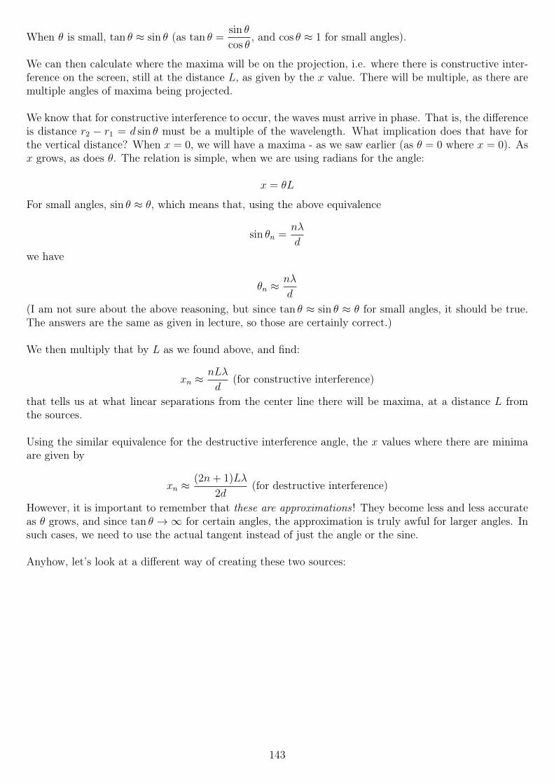
When θ is small, tan θ ≈ sin θ (as tan θ =sin θ
cos θ, and cos θ ≈ 1 for small angles).
We can then calculate where the maxima will be on the projection, i.e. where there is constructive inter-ference on the screen, still at the distance L, as given by the x value. There will be multiple, as there aremultiple angles of maxima being projected.
We know that for constructive interference to occur, the waves must arrive in phase. That is, the differenceis distance r2 − r1 = d sin θ must be a multiple of the wavelength. What implication does that have forthe vertical distance? When x = 0, we will have a maxima - as we saw earlier (as θ = 0 where x = 0). Asx grows, as does θ. The relation is simple, when we are using radians for the angle:
x = θL
For small angles, sin θ ≈ θ, which means that, using the above equivalence
sin θn =nλ
d
we have
θn ≈nλ
d
(I am not sure about the above reasoning, but since tan θ ≈ sin θ ≈ θ for small angles, it should be true.The answers are the same as given in lecture, so those are certainly correct.)
We then multiply that by L as we found above, and find:
xn ≈nLλ
d(for constructive interference)
that tells us at what linear separations from the center line there will be maxima, at a distance L fromthe sources.
Using the similar equivalence for the destructive interference angle, the x values where there are minimaare given by
xn ≈(2n+ 1)Lλ
2d(for destructive interference)
However, it is important to remember that these are approximations ! They become less and less accurateas θ grows, and since tan θ →∞ for certain angles, the approximation is truly awful for larger angles. Insuch cases, we need to use the actual tangent instead of just the angle or the sine.
Anyhow, let’s look at a different way of creating these two sources:
143
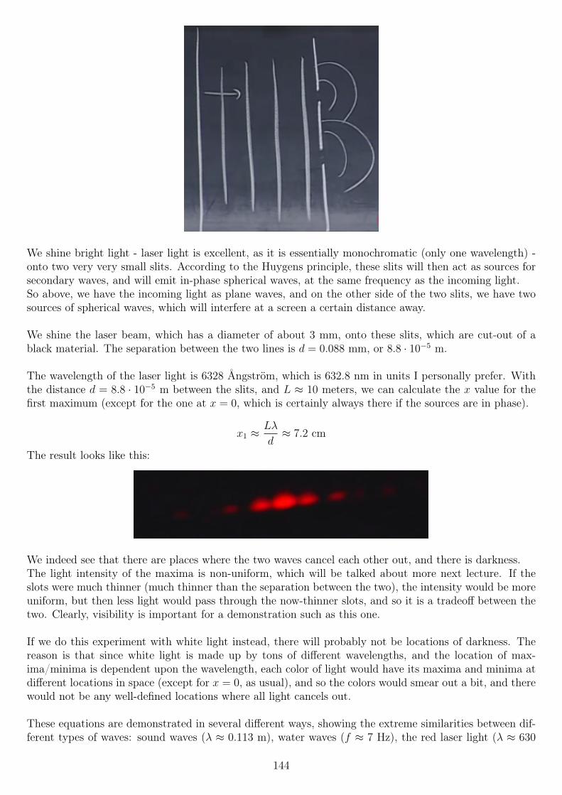
We shine bright light - laser light is excellent, as it is essentially monochromatic (only one wavelength) -onto two very very small slits. According to the Huygens principle, these slits will then act as sources forsecondary waves, and will emit in-phase spherical waves, at the same frequency as the incoming light.So above, we have the incoming light as plane waves, and on the other side of the two slits, we have twosources of spherical waves, which will interfere at a screen a certain distance away.
We shine the laser beam, which has a diameter of about 3 mm, onto these slits, which are cut-out of ablack material. The separation between the two lines is d = 0.088 mm, or 8.8 · 10−5 m.
The wavelength of the laser light is 6328 Ångström, which is 632.8 nm in units I personally prefer. Withthe distance d = 8.8 · 10−5 m between the slits, and L ≈ 10 meters, we can calculate the x value for thefirst maximum (except for the one at x = 0, which is certainly always there if the sources are in phase).
x1 ≈Lλ
d≈ 7.2 cm
The result looks like this:
We indeed see that there are places where the two waves cancel each other out, and there is darkness.The light intensity of the maxima is non-uniform, which will be talked about more next lecture. If theslots were much thinner (much thinner than the separation between the two), the intensity would be moreuniform, but then less light would pass through the now-thinner slots, and so it is a tradeoff between thetwo. Clearly, visibility is important for a demonstration such as this one.
If we do this experiment with white light instead, there will probably not be locations of darkness. Thereason is that since white light is made up by tons of different wavelengths, and the location of max-ima/minima is dependent upon the wavelength, each color of light would have its maxima and minima atdifferent locations in space (except for x = 0, as usual), and so the colors would smear out a bit, and therewould not be any well-defined locations where all light cancels out.
These equations are demonstrated in several different ways, showing the extreme similarities between dif-ferent types of waves: sound waves (λ ≈ 0.113 m), water waves (f ≈ 7 Hz), the red laser light (λ ≈ 630
144
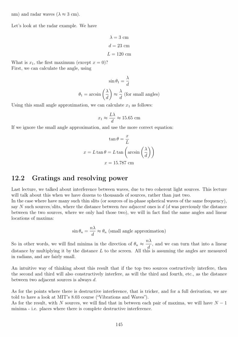
nm) and radar waves (λ ≈ 3 cm).
Let’s look at the radar example. We have
λ = 3 cm
d = 23 cm
L = 120 cm
What is x1, the first maximum (except x = 0)?First, we can calculate the angle, using
sin θ1 =λ
d
θ1 = arcsin
(λ
d
)≈ λ
d(for small angles)
Using this small angle approximation, we can calculate x1 as follows:
x1 ≈Lλ
d≈ 15.65 cm
If we ignore the small angle approximation, and use the more correct equation:
tan θ =x
L
x = L tan θ = L tan
(arcsin
(λ
d
))x = 15.787 cm
12.2 Gratings and resolving powerLast lecture, we talked about interference between waves, due to two coherent light sources. This lecturewill talk about this when we have dozens to thousands of sources, rather than just two.In the case where have many such thin slits (or sources of in-phase spherical waves of the same frequency),say N such sources/slits, where the distance between two adjacent ones is d (d was previously the distancebetween the two sources, where we only had those two), we will in fact find the same angles and linearlocations of maxima:
sin θn =nλ
d≈ θn (small angle approximation)
So in other words, we will find minima in the direction of θn ≈nλ
d, and we can turn that into a linear
distance by multiplying it by the distance L to the screen. All this is assuming the angles are measuredin radians, and are fairly small.
An intuitive way of thinking about this result that if the top two sources costructively interfere, thenthe second and third will also constructively interfere, as will the third and fourth, etc., as the distancebetween two adjacent sources is always d.
As for the points where there is destructive interference, that is tricker, and for a full derivation, we aretold to have a look at MIT’s 8.03 course (“Vibrations and Waves”).As for the result, with N sources, we will find that in between each pair of maxima, we will have N − 1minima - i.e. places where there is complete destructive interference.
145
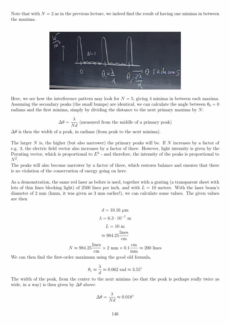
Note that with N = 2 as in the previous lecture, we indeed find the result of having one minima in betweenthe maxima.
Here, we see how the interference pattern may look for N = 5, giving 4 minima in between each maxima.Assuming the secondary peaks (the small bumps) are identical, we can calculate the angle between θ0 = 0radians and the first minima, simply by dividing the distance to the next primary maxima by N :
∆θ =λ
Nd(measured from the middle of a primary peak)
∆θ is then the width of a peak, in radians (from peak to the next minima).
The larger N is, the higher (but also narrower) the primary peaks will be. If N increases by a factor ofe.g. 3, the electric field vector also increases by a factor of three. However, light intensity is given by thePoynting vector, which is proportional to E2 - and therefore, the intensity of the peaks is proportional toN2.The peaks will also become narrower by a factor of three, which restores balance and ensures that thereis no violation of the conservation of energy going on here.
As a demonstration, the same red laser as before is used, together with a grating (a transparent sheet withlots of thin lines blocking light) of 2500 lines per inch, and with L = 10 meters. With the laser beam’sdiameter of 2 mm (hmm, it was given as 3 mm earlier!), we can calculate some values. The given valuesare then
d = 10.16 µm
λ = 6.3 · 10−7 m
L = 10 m
≈ 984.25linescm
N ≈ 984.25linescm× 2 mm× 0.1
cmmm
≈ 200 lines
We can then find the first-order maximum using the good old formula,
θ1 ≈λ
d≈ 0.062 rad ≈ 3.55
The width of the peak, from the center to the next minima (so that the peak is perhaps really twice aswide, in a way) is then given by ∆θ above:
∆θ =λ
Nd≈ 0.018
146
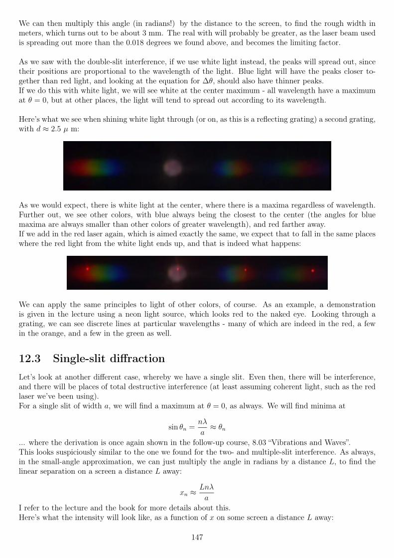
We can then multiply this angle (in radians!) by the distance to the screen, to find the rough width inmeters, which turns out to be about 3 mm. The real with will probably be greater, as the laser beam usedis spreading out more than the 0.018 degrees we found above, and becomes the limiting factor.
As we saw with the double-slit interference, if we use white light instead, the peaks will spread out, sincetheir positions are proportional to the wavelength of the light. Blue light will have the peaks closer to-gether than red light, and looking at the equation for ∆θ, should also have thinner peaks.If we do this with white light, we will see white at the center maximum - all wavelength have a maximumat θ = 0, but at other places, the light will tend to spread out according to its wavelength.
Here’s what we see when shining white light through (or on, as this is a reflecting grating) a second grating,with d ≈ 2.5 µ m:
As we would expect, there is white light at the center, where there is a maxima regardless of wavelength.Further out, we see other colors, with blue always being the closest to the center (the angles for bluemaxima are always smaller than other colors of greater wavelength), and red farther away.If we add in the red laser again, which is aimed exactly the same, we expect that to fall in the same placeswhere the red light from the white light ends up, and that is indeed what happens:
We can apply the same principles to light of other colors, of course. As an example, a demonstrationis given in the lecture using a neon light source, which looks red to the naked eye. Looking through agrating, we can see discrete lines at particular wavelengths - many of which are indeed in the red, a fewin the orange, and a few in the green as well.
12.3 Single-slit diffractionLet’s look at another different case, whereby we have a single slit. Even then, there will be interference,and there will be places of total destructive interference (at least assuming coherent light, such as the redlaser we’ve been using).For a single slit of width a, we will find a maximum at θ = 0, as always. We will find minima at
sin θn =nλ
a≈ θn
... where the derivation is once again shown in the follow-up course, 8.03 “Vibrations and Waves”.This looks suspiciously similar to the one we found for the two- and multiple-slit interference. As always,in the small-angle approximation, we can just multiply the angle in radians by a distance L, to find thelinear separation on a screen a distance L away:
xn ≈Lnλ
a
I refer to the lecture and the book for more details about this.Here’s what the intensity will look like, as a function of x on some screen a distance L away:
147
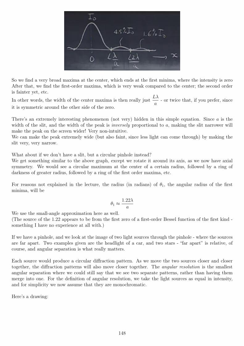
So we find a very broad maxima at the center, which ends at the first minima, where the intensity is zeroAfter that, we find the first-order maxima, which is very weak compared to the center; the second orderis fainter yet, etc.
In other words, the width of the center maxima is then really justLλ
a- or twice that, if you prefer, since
it is symmetric around the other side of the zero.
There’s an extremely interesting phenomenon (not very) hidden in this simple equation. Since a is thewidth of the slit, and the width of the peak is inversely proportional to a, making the slit narrower willmake the peak on the screen wider! Very non-intuitive.We can make the peak extremely wide (but also faint, since less light can come through) by making theslit very, very narrow.
What about if we don’t have a slit, but a circular pinhole instead?We get something similar to the above graph, except we rotate it around its axis, as we now have axialsymmetry. We would see a circular maximum at the center of a certain radius, followed by a ring ofdarkness of greater radius, followed by a ring of the first order maxima, etc.
For reasons not explained in the lecture, the radius (in radians) of θ1, the angular radius of the firstminima, will be
θ1 ≈1.22λ
a
We use the small-angle approximation here as well.(The source of the 1.22 appears to be from the first zero of a first-order Bessel function of the first kind -something I have no experience at all with.)
If we have a pinhole, and we look at the image of two light sources through the pinhole - where the sourcesare far apart. Two examples given are the headlight of a car, and two stars - “far apart” is relative, ofcourse, and angular separation is what really matters.
Each source would produce a circular diffraction pattern. As we move the two sources closer and closertogether, the diffraction patterns will also move closer together. The angular resolution is the smallestangular separation where we could still say that we see two separate patterns, rather than having themmerge into one. For the definition of angular resolution, we take the light sources as equal in intensity,and for simplicity we now assume that they are monochromatic.
Here’s a drawing:
148
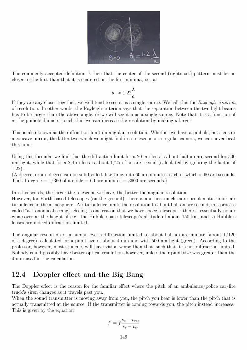
The commenly accepted definition is then that the center of the second (rightmost) pattern must be nocloser to the first than that it is centered on the first minima, i.e. at
θ1 ≈ 1.22λ
a
If they are any closer together, we well tend to see it as a single source. We call this the Rayleigh criterionof resolution. In other words, the Rayleigh criterion says that the separation between the two light beamshas to be larger than the above angle, or we will see it a as a single source. Note that it is a function ofa, the pinhole diameter, such that we can increase the resolution by making a larger.
This is also known as the diffraction limit on angular resolution. Whether we have a pinhole, or a lens ora concave mirror, the latter two which we might find in a telescope or a regular camera, we can never beatthis limit.
Using this formula, we find that the diffraction limit for a 20 cm lens is about half an arc second for 500nm light, while that for a 2.4 m lens is about 1/25 of an arc second (calculated by ignoring the factor of1.22).(A degree, or arc degree can be subdivided, like time, into 60 arc minutes, each of which is 60 arc seconds.Thus 1 degree = 1/360 of a circle = 60 arc minutes = 3600 arc seconds.)
In other words, the larger the telescope we have, the better the angular resolution.However, for Earth-based telescopes (on the ground), there is another, much more problematic limit: airturbulence in the atmosphere. Air turbulence limits the resolution to about half an arc second, in a processcalled “astronomical seeing”. Seeing is one reason that we have space telescopes: there is essentially no airwhatsover at the height of e.g. the Hubble space telescope’s altitude of about 150 km, and so Hubble’slenses are indeed diffraction limited.
The angular resolution of a human eye is diffraction limited to about half an arc minute (about 1/120of a degree), calculated for a pupil size of about 4 mm and with 500 nm light (green). According to theprofessor, however, most students will have vision worse than that, such that it is not diffraction limited.Nobody could possibly have better optical resolution, however, unless their pupil size was greater than the4 mm used in the calculation.
12.4 Doppler effect and the Big BangThe Doppler effect is the reason for the familiar effect where the pitch of an ambulance/police car/firetruck’s siren changes as it travels past you.When the sound transmitter is moving away from you, the pitch you hear is lower than the pitch that isactually transmitted at the source. If the transmitter is coming towards you, the pitch instead increases.This is given by the equation
f ′ = fvs − vrecvs − vtr
149
... where f is the original frequency, f ′ is the frequency received/percieved/heard, vs the speed of soundin air, vrec the velocity of the receiver and vtr the velocity of the transmitter.In this equation and in what follows, we take the velocities as positive when moving towards the right ofthe blackboard, and negative when moving towards the left.
Note that the case of a stationary transmitter and a receiver moving away is not equal to the case of aastationary receiver where the transmitter is moving away!
If the transmitter is stationary, and is at say 440 Hz (the standard tuning in modern music is to the A440note), and the receiver moves away at the speed of sound, then there will be no sound heard at all - thereceiver (just barely) outruns the sound waves entirely. The equation above gives 0 Hz for that case -granted, it sounds weird talk about a 0 Hz sound, but since 0 Hz means no wave motion, I suppose thatis technically true.
On the other hand, if the transmitter is moving away at the speed of sound, while the transmitter isstationary, what do we find?
f ′ = 440340− 0
340− (−340)= 220 Hz
The frequency is halved, but we still hear the sound. If you find that unintuitive, think about it a bitmore - it’s very clear that while the transmitter moves, the waves will still reach you as they always travelat 340 m/s in your direction.
The equation also has a very curious effect, which can be hard to show in practice: if the transmitter ismoving away at twice the speed of sound, the sound (a piece of music, perhaps) will reach a stationaryobserver in time and in tune, but backwards !
How do we intuitively explain the Doppler effect? It is actually quite simple, but is best shown usinganimated graphics, which I can’t really use here. I suggest looking it up online.In short, when moving towards a transmitter (or the transmitter is moving towards you), the wave frontsbecome “compressed”, and the wavelength becomes shorter (meaning that for sound, the pitch increases;for light, it becomes blueshifted ; more on that soon). When the distance between is increasing, the wavefronts become separated from each other, and the wavelength becomes longer (sound: lower pitch; light:“redder” color, or redshift).
12.4.1 The Doppler effect and light
Let’s look more at the Doppler effect in light (and other EM radiation).The derivation requires special relativity, but the result is given by
f ′ = f
(1− β1 + β
)1/2
whereβ =
v
cwhere v is the relative velocity between the transmitter and receiver, and c is the speed of light.If β > 0, then the two are moving apart; if β < 0 the two are approaching each other.
Much of the idea behind special relativity, as the name implies, is that motion is relative. There is no suchthing as an absolute reference frame, and therefore, there is only one term of velocity in the equation. Itdoes however, of course, matter whether the two are approaching or receding from each other.The reason this doesn’t apply to the sound waves above is that sound waves require a medium to travelthrough, whereas electromagnetic do not.
150
In terms of wavelength, which is physically identical but perhaps more useful, we find (as λ =c
fand thus
λ′ =c
f ′):
λ′ = λ
(1 + β
1− β
)1/2
Note that the denominator and numerator have swapped places, as compared to the frequency-based equa-tion.
The velocity v in the above equations is the radial velocity. If the velocity between the source and thereceiver is not is the straight line connecting the two, then there is an angle θ between the velocity vectorand the position vector between the tow. The velocity we need is then given by v cos θ, which is a resultwe’ve seen many times before when using vectors. Only the component of the velocity in the direction ofthe object matters.
Police often use “radar guns”, which can measure the speed of cars by reflecting radar waves of a knownfrequency/wavelength off cars, and measure the wavelength of the returning waves. The radial velocity ofthe car can then be calculated.
12.4.2 Big Bang cosmology
Doppler shift is also used by astronomers to calculate the radial velocity of distant stellar objects. Moststellar spectra consist of lines, spectral lines, of a discrete wavelength, from the atoms and molecules thatthey consist of.If we happen to know a certain spectral line, and we see the same line, but shifted in wavelength, we havetwo names for that, as mentioned earlier:
λ′ > λ: redshift
λ′ < λ: blueshift
So if the actual wavelength, from the stellar object, is shorter than we would have expected, that meansthe object is approaching us (the light is blueshifted), and vice versa if it is longer than expected (the lightis redshifted).
Strictly speaking, if a spectral line is at e.g. 1000 nm when stationary, and say 1100 nm when measured,we still call that redshift, despite that it is technically moving away from the red (red being at 620-700nm or so) now that the wavelength has surpassed that of red.The same applies to blueshift: any decrease in wavelength is known as blueshift, and any increase is knownas redshift, regardless of the actual wavelengths involved.
If we know a certain spectral line, as above, and we can generate that same spectral line in our observatory,we can compare the two, and via the equation above, find β and then find v = βc, and so we know therelative radial velocity between us and the object (perhaps a star, or an entire galaxy).
Edwin Hubble, the astronomer after which the Hubble Space Telescope is named, discovered a curiousrelation between the radial velocity of a galaxy and its distance.The further away a galaxy is, the higher its redshift is. In other words, the further away it is, the fasterit is moving away from us! This fairly linear relation it known as Hubble’s law, and the constant of pro-portionality H or H0 (the latter is commonly used for the current value, as it actually changes over largetime periods) is known as the Hubble constant. The value of this constant was most recently measured(on March 21 2013) to be 67.80± 0.77 km/s/Mpc (kilometers per second per megaparsec).One parsec is about 3.26 light years, so a megaparsec is 3.26 · 106 light years, or about 3.1 · 1019 km.
151
The value has fluctuated over time, however, as measurements have gotten more precise. (Hubble’s originalmeasurement was on the order of 500 km/s/Mpc!)
Hubble’s law, in mathematical form, states that
v = H0d
where v is then measured in km/s, H0 in km/s/Mpc and d in Mpc.
As an example, if we see an absorption line in the spectrum of a galaxy that is is 7% shifted towards thered, we can calculate β by solving the wavelength equation for β:
β =(λ′)2 − λ2
(λ′)2 + λ2
If we plug in λ′ = 1.07λ (λ′ > λ, or else it’s not redshifted but blueshifted), we find
β ≈ 0.0675556
If we then use v = βc, we find
v ≈ 20266 km/s
We can then calculate the approximate distance using Hubble’s law:
v = H0d
d =v
H0
≈ 20266
67.80≈ 298.9 Mpc
One way to describe why this happens is to assume we are at the “center” of the universe, which wasformed from a single point, if we only turn back the clock. The galaxies that obtained the largest speedat that initial explosion (the Big Bang) are not the furthest away from us.This isn’t strictly true, as the universe doesn’t even have a center according to current theories on theshape of the universe. (For a two-dimensional analogue, think about the surface of a balloon/sphere:where on the surface is the center? The universe can be thought of in a similar way, except we have threedimensions rather than two.)That’s also ignoring that there were no galaxies right after the Big Bang. Still, let’s assume this is truefor now.
We can then ask the question: if the universe had a beginning, where everything was together, as we wouldsee it if we simply ran time backwards (everything would get closer and closer to everything else), howlong ago did this happen?
According to data from two probes that monitor the Cosmic Microwave Background Radiation (CMBR),the WMAP (“W-map”, the Wilkinson Microwave Anisotropy Probe) and the Planck satellite, essentiallythe successor to WMAP, the universe is 13.798±0.037 billion years old. Numbers in this order of magnitudeare widely accepted in the scientific community, and indeed there is plenty of proof, such as very, very oldknown galaxies that are only a few hundred million years younger than the universe itself.As a side note, the solar system and Earth are about 4.5 billion years old, while life on Earth (simple cells)are thought to have existed for about 3.6 billion years.
12.5 Farewell specialI didn’t take any notes for this lecture. While the content is certainly interesting, I’m not sure exactlywhat to write down for it; it must certainly be seen either way.
152
Chapter 13
Homework problems
13.1 Week 2
13.1.1 Problem 1: Motion of charged particle in electric field
“An electron of mass me and charge q = −e is injected horizontally midway between two very largeoppositely charged plates. The upper plate has a uniform positive charge per unit area +σ and the lowerplate has a uniform negative charge per unit area −σ . You may ignore all edge effects. The particle hasan initial velocity ~v0 = v0x.
′′
a) What is the magnitude [and direction] of the electric field between the plates?
I didn’t bother solving this one manually, since I remembered the answer. Each infinite plate has a fieldmagnitude of
σ
2ε0. The positive, top plate has a field pointing outwards, while the bottom, negative plate
has a field pointing inwards.Since they are acting in the same direction between the plates, the answer is twice the above. Thus, theelectric field between the two plates is ~E =
σ
ε0(−y)
b) What is the magnitude of the acceleration of the electron when it is between the plates?
~F = m~a, so ~a =~F
m. ~F is given by the electric field strength times the magnitude charge e: ~F =
eσ
ε0Therefore,
|~a| = eσ
ε0me
c) What is the y-component of the position of the particle when it reaches the plane defined by x = L?This one is a bit harder to calculate - unless my solution is a bad one.
We were given that the initial velocity is purely in the x direction, and the electric force (the only forcewe are to calculate) acts strictly in the y direction. Therefore, the velocity in the x direction will in factbe constant, so we can easily calculate the time t taken for the electron to reach x = L:
t =L− x0
v0
=L
v0
We can now use a fairly complex equation from mechanical physics - it can a least be complex with allvalues filled with expressions:
yfinal = yinitial + vinitialyt+1
2ayt
2
yinitial is given as 0, as is vinitialy , so that simplifies our situation a lot:
153
yfinal =1
2ayt
2
We found the acceleration previously; we just need to multiply it by t2, where we found t =L
v0
:
yfinal =eσ
2ε0me
(L
v0
)2
That concludes problem 1!
13.1.2 Problem 2: Three plates capacitor
“Three infinite uniformly charged thin sheets are shown in the figure below. The sheet on the left atx = −d is charged with charge per unit area of −3σ , The sheet in the middle at x = 0 is charged withcharge per unit area of +σ, and the sheet on the right at x = d is charged with charge per unit area of−2σ . Find the x component of the electric field Ex in each of the regions 1, 2, 3, and 4.”The figure is simply three vertical lines, the sheets, and four regions. Region 4 is to the left of all ofthe sheets, region 3 between the rightmost and the middle sheet, region 2 between the middle and therightmost sheet, and region 1 to the right of all the sheets.
This problem is very straightforward, as long as you know the electric field of an infinite plate to beE =
σ
2ε0.
We then calculate the electric field due to each plate, and use superposition to add them together, keepingthe directions in mind for each region.
E1 =−3σ
ε0
E2 =σ
ε0
E3 =−2σ
ε0
Region 1:σ
2ε0· (−2 + 1− 3)
Region 2:σ
2ε0· (−3 + 1 + 2) = 0
Region 3:σ
2ε0· (−3− 1 + 2)
Region 4:σ
2ε0· (3− 1 + 2)
That’s really all there is to it!
13.1.3 Problem 3: Electric field, potential, and electrostatic potential energy
“Point charges Q1, Q2, and Q3 reside on three corners of a square with sides of 1 m; the distance from Q2
to P3 is 2m (see diagram).”
(a) What is the electric potential, V , at P1? (Normalize the potential to be zero at ∞ and give youranswers in Volts). (Note: P1 is located at the “unoccupied” corner of the square.)
Well, we begin by calculating the electric potetial V for each of the charges alone, using V =Q
4πε0r:
154
VQ1 =−11 · 10−6
4πε0r
VQ2 =−3 · 10−6
4πε0r
VQ3 =−7 · 10−6
4πε0r
The question then asks for the potentials at P1, P2 and P3. All we have to do is to add the three potentialsabove, while substituting the distance to that point from each charge for r. That is a mess to write, buteasy to do, so I’ll leave that to the reader. It’s either as simple as 1 m or 3 m, or you’ll have to use thePythagorean theorem.
(b) Are there points or surfaces in space (other than infinity) where V is zero?
Yes. We have both positive and negative charges, which means we will have both positive and negativepotentials at different locations in space. Potentials don’t charge abruptly, so in an area where the po-tential transitions from positive to negative or vice versa, there will be a point where it exactly equals zero.
(c) What is the electrostatic potential energy of the system? Express your answer in Joules.
To solve this, we add up the electrostatic potential energies of each pair of charges:
Utotal = U12 + U13 + U23
Since U = qV , this is the potential at each point times the charge at that point, e.g.
U12 = V1 ·Q2
U13 = V1 ·Q3
U23 = V2 ·Q3
For r, part of the potentials, we use the distance between the two charges in question.The answer to the question is then Utotal.
(d) Suppose we release the three charges so that they can move freely in empty space. How much energyis released in the form of kinetic energy?
This is the only question of the homework so far that I didn’t solve on my own, even with the book andGoogle. The correct answer is “The question is not well defined”, if I’ve understood it correctly becausethe answer depends on the order you release the charges in, and (I think?) the times you do so.I still don’t see how there can be anything but one correct answer, if you release them all exactly simul-taneously, though, even if we haven’t learned how to calculate it.
13.1.4 Problem 4: Electric field of a charged ring
“A point-like negatively charged particle of mass m and charge −q is initially released from rest from thepoint P along the positive z-axis where the magnitude of the electric field is largest.”The diagram shows a charged ring, with radius R and total charge Q, centered on the z axis and locatedo the x-y plane. The point P has coordinates (0, 0, z), where we are to find z:(a) What is the distance from the point P to the origin? Express your answers in terms of the followingvariables, if relevant: q, m, R, Q, and ε0.
155
Well, all we know about P is that the magnitude of the electric field is the maximum there. Clearly, ourfirst task is to find the electric field due to the ring, to begin with!
By symmetry arguments, along the z axis, the x and y components of the electric field will cancel out, sowe only care about the magnitude of the z component, Ez.
First, we divide the ring into tiny segment ~d`, each of which carries a charge dq =Q
2πR(the charge
distribution is uniform, though the problem didn’t actually state that).
Each of these contribute a small amount ~dE to the total electric field at the point we are interested in.The distance between a point on the ring and P is given by r =
√R2 + z2, via the Pythagorean theorem.
So far, we have (from Coulomb’s law)
dE =dq
4πε0r2=
Q
8π2ε0r2R
We are only interested in the z component, dEz = dE cos θ (by vector decomposition), with θ being theangle between the point P and d` (if we draw a line between the two, the angle is what that line makeswith the z axis).Via geometry, we can find see cos θ =
z
r. If we make this substitution, and then substitute the value for
r =√R2 + z2:
dEz =Q
8π2ε0r2Rcos θ =
Q
8π2ε0r2R
z
r
dEz =Qz
8π2ε0r3R
dEz =Qz
8π2ε0R(√R2 + z2)3
dEz =Qz
8π2ε0R(R2 + z2)3/2
Finally, we want to integrate this over the entire circle. That turns out to be an easy integral, becauseeverything above is a constant!
Ez =
∮dEz d`
The infinitesimal segment d` = Rdθ (arc length):
Ez =
∫ 2π
0
dEz Rdθ =
∫ 2π
0
Qz
8π2ε0R(R2 + z2)3/2Rdθ
Ez =Qz
8π2ε0(R2 + z2)3/2
∫ 2π
0
dθ
Ez =Qz
4πε0(R2 + z2)3/2
We want to know where the field is at its maximum, so we start off by calculating the derivative of theelectric field:
d
dz
(1
4πε0
Qz
(R2 + z2)3/2
)=
Q(R2 − 2z2)
4ε0π(R2 + z2)5/2
For that, I thank Mathematica. We then set the derivative equal to zero, to find extreme points; we knowthat Pz > 0, so we can discard the negative solution we find. One solution remains:
156
Pz =R√
2
... which answers part (a).
(b) What is the speed of the particle when it reaches the origin? Express your answers in terms of thefollowing variables, if relevant: q, m, R, Q, and ε0.
For this part, we want to know the potential difference between P and the origin. One way of doing thatis to integrate the electric field dot the direction vector. However, we know that they point in the samedirection (z), so we can skip the dot product and do a regular integration with dz:
VP − Vorigin =
∫ 0
Pz
~E · ~dz =Q
4πε0
∫ 0
Pz
z
(R2 + z2)3/2dz =
(Q
4πε0
)(1
R− 1√
R2 + z2
)I admit, more Mathematica for that integral.At least now the worst part is over. Only algebra remains.
We now know the potential difference, and can very easily calculate the potential energy difference bymultiplying the voltage difference by −q, the charge of the particle.Via conservation of energy, the gain/loss in potential energy plus the gain/loss in kinetic energy mustequal zero:
∆U + ∆Ke = 0
The particle is released from rest, so Ke starts at zero, and ∆Ke = Ke. ∆U is
∆U = ∆V · (−q)
So what is ∆Ke? It’s the kinetic energy the particle has when it reaches the origin. We use classicalmechanics for this, so
∆Ke =1
2mv2
We set the sum of the two equal to zero, and solve for the velocity v, which will be our answer:
∆U + ∆Ke = 0
∆V · (−q) +1
2mv2 = 0
2∆V · (−q) +mv2 = 0
mv2 = −2∆V · (−q)
v2 =2∆V · qm
v =
√2∆V · qm
Almost done! The only thing left is to put our ugly expression for ∆V in there... Hold on:
v =
√√√√2((
Q4πε0
)(1R− 1√
R2+z2
))· q
m
... actually, I lied. z isn’t allowed in the answer, but we solved that the point in question has z =R√
2.
157
v =
√√√√√2
((Q
4πε0
)(1R− 1√
R2+( R√2
)2
))· q
m
... and that can be our final answer, if we choose to not clean it up.
13.1.5 Problem 5: Two spherical conductors
“Two spherical conductors, A and B, are placed in vacuum. A has a radius rA = 25 cm and B of rB = 35cm. The distance between the centers of the two spheres is d = 225 cm.A has a potential of VA = 110 volts and B has a potential of VB = −40 volts.”
(a) An electron is released with zero speed from B. What will its speed be as it reaches A? Express youranswer in m/sec.
The distance betwee is in fact superfluous information! We can calculate this using only the potentialdifference:
VB − VA = −150 V
VA − VB = 150 V
(We’ll need both, as part (b) asks about a proton.)
The kinetic energy (in classical mechanics) is:
Ke =1
2mv2
We can solve that for v and use the equation to convert from potential energy to velocity:
Ke =1
2mv2
2Ke
m= v2
v =
√2Ke
m
So with that done, we need to know Ke and m. m is the mass, which for an electron is about 9.109 · 10−31
kg. Ke can be found easily by the definition of the electron volt (eV):
1 eV = 1 e · 1 V = 1.602 · 10−19 J
where e is the elementary charge. We have a potetial difference of 150 volts, so
Ke = 150 V · e = 150 · 1.602 · 10−19 J
If we substitute that in the velocity equation, we get
v =
√2 · (150 · 1.602 · 10−19)
9.109 · 10−31≈ 7.264 · 106 m/s
... which is our answer for (a).
(b) A proton is released with zero speed from A. What will its speed be as it reaches B? Express youranswer in m/sec.
158
The charge of a proton is exactly the opposite of the electron, i.e. the magnitude is the same. Since thequestion is now reversed (A to B instead of B to A), the only thing we need to charge from the answerabove is the mass. A proton’s mass is about 1.673 · 10−27, so:
v =
√2 · (150 · 1.602 · 10−19)
1.673 · 10−27≈ 1.69 · 105 m/s
Due to the much greater mass, the proton arrives with a much lower velocity than the electron.
(c) We now change the potential of B to VB = +25 volts. For this new configuration, what is the ratio ofthe speed of the electron (as it arrives at A) and the speed of the proton (as it arrives at B)?
To solve this one, we recalculate the potential difference to be of magnitude 85 volts, and substitute thatin our equations:
velectron =
√2 · (85 · 1.602 · 10−19)
9.109 · 10−31≈ 5.464 · 106 m/s
vproton =
√2 · (85 · 1.602 · 10−19)
1.673 · 10−27≈ 1.275 · 105 m/s
The ratio, and answer, is then
velectronvproton
≈ 5.464 · 106
1.275 · 105≈ 42.85
... which answers (c), and we are done!
13.1.6 Problem 6: Two conducting hollow cylinders
“Two conducting thin hollow cylinders are co-aligned. The inner cylinder has a radius R1, the outer has aradius R2. Calculate the electric potential difference V(R2) - V(R1) between the two cylinders. The innercylinder has a surface charge density of σa = −σ, where σ > 0, and the outer surface has a surface chargedensity of σb = 3σ.
The cylinders are much much longer than R1. Thus, you may ignore end effects and neglect the thicknessof the cylinders.
(a) What is the electric potential difference between the outer cylinder and the inner cylinder V(R2) -V(R1)?
Okay, let’s get to work! We choose a co-axial Gaussian cylinder and place it in between the two cylinders,such that it encloses the inner, but not the outer cylinder.Because they are co-axial, we don’t need the surface integral from Gauss’s law, but can use EA instead:
EA =Qins
ε0
A is the surface area of our Gaussian surface 2πr`, where r is the radius and ` the length.What is Qins? Well, it’s the enclosed surface area of the inner cylinder, 2πR1`, times the charge densityσa = −σ: −2πR1`σ. Thus we have
2πr`E = −2πR1`σ
ε0
We can cancel out a few terms, and solve for E:
159
rE = −R1σ
ε0
E = −R1σ
ε0r
This is the the electric field for R1 < r < R2, i.e. between the cylinders. Keep in mind that this is notvalid for the later sub-questions!
Now then. The question was about the potential difference, so we integrate the field dot the direction ~dr,from R2 to R1:
V(R2)− V(R1) =
∫ R1
R2
−R1σ
ε0r· ~dr = −R1σ
ε0
∫ R1
R2
dr
r
Because we know ~dr and ~E to both be radially outwards, we reduce the integral to a very, very simpleone. ∫ R1
R2
dr
r= ln r
∣∣∣R1
R2
= lnR1 − lnR2 = ln
(R1
R2
)Let’s add in the rest, the constant stuff we had before the integral:
V(R2)− V(R1) = −R1σ
ε0ln
(R1
R2
)That answers question (a)!
(b) What is the magnitude of the electric field outside the cylinders, r > R2?
Well, let’s do what we did for (a), since that worked a treat. Th difference here is that Qins has changed,but the calculation is the same other than that. Where we had −2πR1`σ, we now have a density thatdepends on R1 and R2 as well as two sigmas. Let’s start over with Gauss’s law:
EA =Qins
ε0
A is still the area of the Gaussian surface, so A = 2πr`. Now, let’s find Qins:
QA = −σR1 · 2π`
QB = 3σR2 · 2π`
Qins = QA +QB = σ(3R2 −R1) · 2π`
Put it all together:
2πr`E =σ(3R2 −R1) · 2π`
ε0
rE =σ(3R2 −R1)
ε0
E =σ(3R2 −R1)
ε0r
... which answers (b).
160
(c) What is the electric potential difference between a point at a distance r = 2R2 from the symmetry axisand the outer cylinder V(2R2) - V(R2)?
We’ll need to integrate the electric field again.
V(2R2)− V(R2) =
∫ R2
2R2
σ(3R2 −R1)
ε0r· ~dr =
σ(3R2 −R1)
ε0
∫ R2
2R2
dr
r
We have already solved that integral: it is ln
(R2
2R2
). Thus, we have
V(2R2)− V(R2) =σ(3R2 −R1)
ε0ln
(R2
2R2
)... which answers (c), and we are done!
13.1.7 Problem 7: Speed of an electron
Finally, the last problem of the week. Writing these down in this LATEXdocument has taken a lot of time- I’ve essentially re-solved them from scratch, having only a few scratch equations left from when I solvedthem the first time. That is surely an excellent way to learn and truly understand, though!
“An electron is projected, with an initial speed of vi = 1.74e+ 05 m/sec, directly towards a proton that isessentially at rest. If the electron is initially a great distance from the proton, at what distance from theproton is its speed instantaneously equal to twice its initial value? Express your answer in meters.”My first instinct was that more information must be required, but as expected (they wouldn’t ask unan-swerable questions!), we can solve this. Fairly easily, too, once we know how.
We know the initial velocity, and so we can calculate the initial kinetic energy. We also know the finalvelocity - twice the original one - and can calculate the final kinetic energy. Via conservation of energy,the difference is the two is the change in electric potential energy ∆U , which we can relate the the electricpotential V of the proton, to find the distance between them.
So, let’s begin. First, the initial kinetic energy of the electron is
Keinitial=
1
2mevinitial
2
Kefinal=
1
2mevfinal
2 =1
2me(2vinitial)
2
∆U =1
2me(2vinitial)
2 − 1
2mevinitial
2 =1
2me
((2vinitial)
2 − vinitial2)
Let’s now find the electric potential due to the proton. That one is easy - we know the formula:
V =Qp
4πε0r
The distance between the two is initially “great”, so we treat it as if the electric potential energy is 0 tobegin with. Thus, ∆U = U . We also know that U = V q, where V is the electric potential due to theproton, and q is the charge of the electron.Therefore, we can now set the sum of our two expressions for U equal to zero, and solve for r. The chargeof the electron is q = −e, so we get:
1
2me
((2vinitial)
2 − vinitial2)
+−e ·Qp
4πε0r= 0
Messy, but if we solve for r and substitute Qp = +e, we get:
161
r =e2
6ε0meπvinitial2
If we stick our values in there, we get
r =(1.602 · 10−19)2
6 · (8.854187 · 10−12)(9.109 · 10−31)π(1.74 · 105)2≈ 5.556 · 10−9 m
That is, about 5.56 nanometers! After travelling for a very long distance, it only reaches twice its initialspeed less than a picosecond before they collide. Wow.Finally, last question of the week:In your opinion do we need to worry about the special theory of relativity for the speeds given in thisproblem?
The answer is no. The speed is only about 0.1% of the speed of light, so relativistic effect are negligible.Even at 10% of the speed of light, the relativistic effects are fairly small.
13.2 Week 3
13.2.1 Problem 1: Spherical capacitor
“A capacitor consists of two concentric spherical shells. The outer radius of the inner shell is a = 0.6 mmand the inner radius of the outer shell is b = 2.96 mm.”
(a) What is the capacitance C of this capacitor? Express your answer in Farads.
Let’s begin by stating that capacitance C =Q
V, where V is the potential difference between the two
spheres. Q is a given, so if we find V , we should be able to solve this problem easily. To find V , we canintegrate the electric field between the two radii, so let’s begin by finding the electric field!
We know since before that a spherical shell has the same electric field as a point charge would, as longas you’re outside the shell; and we know that the electric field inside the larger sphere, due to the largersphere, is zero.Therefore the electric field for a < r < b is given by the charge on the inner sphere a only:
~E =Q
4πε0r2r
Va − Vb =
∫ b
a
~E · ~dr =Q
4πε0
∫ b
a
dr
r2r
We know that the electric field from a sphere is radially outwards and thus always parallel to dr, so we
can ignore the vectors and the dot product, and simply integrate1
r2and evaluate at the limits:
Va − Vb =Q
4πε0
∫ b
a
dr
r2=
Q
4πε0
(−1
r
∣∣∣ba
)=
Q
4πε0
(1
a− 1
b
)The latter part of the result can be simplified:
1
a− 1
b=b− aab
And therefore, the reciprocal, which we’ll need very soon, is
11a− 1
b
=ab
b− a
162
Now then. Back to our potential difference result. Now that we have V (the potential difference Va − Vb)we can divide Q by that, which will get rid of the Q and flip everything else upside down, so we get:
C =Q
V= 4πε0
ab
b− aWe were asked to answer numerically, for a = 0.6 mm and b = 2.96 mm:
C = 4πε0(0.6 · 10−3)(2.96 · 10−3)
2.96 · 10−3 − 0.6 · 10−3≈ 8.37299 · 10−14 F
(b) Suppose the Maximum possible electric field at the outer surface of the inner shell before the air startsto ionize is Emax(a) = 3.0·106 V·m−1. What is the maximum possible charge on the inner sphere? Expressyour answer in Coulombs.
Well, the magnitude of the electric field is (again) given by:
E =Q
4πε0r2
If we solve the equation for Q and substitute E = 3 · 106 V/m and r = a = 0.6 · 10−3 m we should get theanswer:
Q = 4πε0r2E = 4πε0(0.6 · 10−3)2(3 · 106) ≈ 1.2059 · 10−10 C
(c) What is the maximum amount of energy stored in the capacitor? Express your answer in Joules.
The energy stored can be calculated in these ways:
Energy stored =1
2CV 2 =
1
2QV =
1
2
Q2
C
Since we know Q and C, we prefer the latter form, and so our answer is
1
2
Q2
C≈ 8.6838 · 10−8 J
(d) When E(a) = 3.0 ·106 V ·m−1 what is the absolute value of the potential difference between the shells?Express your answer in Volts.
We have the equation from the potential difference from question (a), we have the charge of a at thisE-field strength from question (b), and we have the value of all the constants required to find the answer:
|∆V | =∣∣∣∣ Q4πε0
b− aab
∣∣∣∣ =
∣∣∣∣(1.2059 · 10−10
4πε0
)(2.96− 0.6) · 10−3
(2.96 · 10−3) · (0.6 · 10−3)
∣∣∣∣ ≈ 1435.1 V
13.2.2 Problem 2: Coaxial cylinders
“A very long cylindrical capacitor consists of two thin hollow conducting cylinders with the same axis ofsymmetry. The inner cylinder has a radius a, the outer one has a radius b. You may ignore end effects.”There is a figure that shows the inner cylinder with charge +Q and the outer with charge −Q.
(a) What is the capacitance per unit length?
Well, we need to do roughly the same thing as we did with the sphere. First, we want to find the electricfield.Let’s set up a Gaussian cylinder with a < r < b. The total charge on the cylinder is Q, so the charge per
unit length is λ =Q
`. Via Gauss’s law, we have that
163
EA =Qenc
ε0
A is the surface area, so:
E2πr` =Qenc
ε0
E =Qenc
2πr`ε0
The enclosed charge is the charge per unit length λ times the length, so:
E =λ`
2πε0r`
E =λ
2πε0r
The ` cancels - anything else would be bizarre; surely the length we choose for the Gaussian cylinder can’tchange the electric field strength.
We carry out the good old integration to find the potential difference:
Va − Vb =
∫ b
a
~E · dr =λ
2πε0
∫ b
a
dr
r=
λ
2πε0ln
(b
a
)We know that C =
Q
V, and Q = λ`:
C =λ`
|Va − Vb|=
2πε0`
ln(ba
)The question asked for the capacitance per unit length, so the ` disappears.
C =2πε0
ln(ba
)(b) Now consider the limit where b is very close to a. Express b as a + δ; where
δ
a 1. What is the
capacitance per unit length in that limit? Hint: in that limit you can use the following approximation:ln (1 + x) ≈ xExpress your answer in terms of a, δ and ε0.
OK, well, we can rewrite with b = δ and see how that looks:
C =2πε0
ln(a+δa
) =2πε0
ln(1 + δ
a
)Following the hint, we then ignore the 1 and the whole logarithm:
C ≈ 2πε0a
δ
... which is our final answer for (b).
164
13.2.3 Problem 3: The effect of a dielectric medium on capacitance
Consider a capacitor made of two square plates of side `. The distance between the two plates is d.(a) We insert a dielectric of dielectric constant K > 1 and width ` a distance x (as in the diagram). Whatis the total capacitance of this arrangement?
We should be able to treat this like two separate capacitors. From the diagram shown, it seems to me asif we then need to add the capacitance of the two, as they would be connected in parallel. Let’s try thatand see what happens.
The plates have area ` · `, but are then split up into two regions. Sketch it up on paper and it will make alot of sense. The capacitor with the dielectric is then made of sides x and `, so Adielec = lx while the onewithout the dielectric is ` · (`− x) = `2 − lx, which certainly looks sensible.
We have the good old parallel plate capacitor equation:
C =Aε0dK
Let’s call the capacitor without the dileectric C1, and the capacitor with the dielectric C2:
C1 =(`2 − `x)ε0
d
C2 =`xε0dK
Ctotal = C1 + C2 =(`2 − `x)ε0
d+`xε0dK = ε0
((`2 − `x)
d+`x
dK
)(b) The capacitor is now connected to battery which provides a difference of potential V0 across the ca-pacitor. What is the energy stored in the capacitor?
The energy stored is1
2CV 2, so we can mostly copy and paste from the previous answer:
1
2ε0
((`2 − `x)
d+`x
dK
)V0
2
(c) While the battery is still connected to the capacitor, we now move the dielectric slab a bit further inbetween the plates, increasing x by an amount ∆. What is the change in the energy stored in the capacitor?
Well, let’s see. Let’s first calculate the increase in capacitance. First, the new total will be:
Cnew = ε0
((`2 − `(x+ ∆))
d+`(x+ ∆)
dK
)If we subtract the two and simplify, we get the difference in capacitance:
∆C =ε0(K − 1)`∆
d
(The notation becomes slightly awkward as ∆C is not ∆ times C, but rather the change in C. Same for∆E below.)We can then use the half-C V squared formula to find the extra energy stored in ∆C:
∆E =1
2∆CV 2 =
1
2
ε0(K − 1)`∆
dV0
2
165
That answers part (c), or (c1). Then come the highly related follow-ups, which are unlabeled, so let’s callthem (c2) and (c3). First, (c2), with my label:
(c2) What is the work done by the battery while we push the dielectric slab in from its original positionx to x+ ∆? (Make sure you have the correct sign!)
Uh oh! Well, intuitively, I entered the same as for (c1), since it seemed like it would make sense for thebattery’s work to be the same as the added energy. Nope!The correct answer is twice of (c1), so just remove the half factor in the front. The answer to the nextquestion adds some insight...
(c3) What is the work done by us while we push the dielectric slab in? (make sure you have the correct sign!)
The answer here is the negative of (c1). That is, we do negative work, equal in magnitude to the addedcharge on the capacitor. The battery, meanwhile, must provide both the added energy stored in the ca-pacitor and cover up the negative work we do!
The reason this happens is that due to electrostatic forces, the dielectric is pulled into the capacitor.
13.2.4 Problem 4: Coaxial cable with dielectric
“A certain coaxial cable consists of a copper wire, radius a, surrounded by a concentric copper tube ofinner radius c. The space between is partially filled (from b out to c) with material of dielectric constantK. The goal of this problem is to find the capacitance per unit length of this cable. You may neglect edgeeffects.”
Note that there is space a < r < b which is vacuum! Thus, we can not simply calculate a singleelectric field and use that everywhere!
”Note that for technical reasons, we use the symbol ` for charge per unit length, rather than the moretypical λ. Do not get confused, ` is not a length!”Argh, okay then. We’ll see how many times I screw that one up before I remember.
a1) Assume that the copper wire has uniform positive charge per unit length ` and the copper tube hasuniform negative charge per unit length on its inner surface −`. Calculate the radial component of theelectric field in the region 0 < r < a.
Well, since there is no mention of a applied potential difference, and this is conductor, this is the likelythe easiest sub-question of this week: the answer is zero.a2) Calculate the radial component of the electric field in the region a < r < b.
Frankly, I’ve already done that in earlier examples, so I’ll just nick the answer from there. The equationlooks like the one for electric potential due to a point charge, except Q is replaced by the charge per unitlength, and it’s multiplied by two. So:
Er =`
2πε0r
Calculate the radial component of the electric field in the region b < r < c.
In other words, “inside” the dielectric. Well, we just divide the above by the dielectric constant. No more,no less.
166
Er =`
2πε0Kr
Calculate the radial component of the electric field in the region r > c.
Ah, finally some work to do. Well, not really. We apply Gauss’s law and find no net enclosed charge (+`and−` per unit length, respectively, for the two cylinders), so the electric field outside is also zero. Too easy.
(b1) What is the potential difference V(b) - V(a) (be careful about sign)?
Well, is there any work this time around, then? Yes! There is an electric field in the region, that we canintegrate. It is, as per above:
Er =`
2πε0r
As usual, the field is radial and the ~dr vector we would use too, so this is a simple integral:
Vb − Va =
∫ a
b
`
2πε0rdr =
`
2πε0
∫ a
b
dr
r
∣∣∣ab
=`
2πε0ln(ab
)(b2) What is the potential difference V(c) - V(b) (be careful about sign)?Clearly, we need to integrate just as above, but with the field that is also divided by K (see above), andfrom c to b instead of b to a. We can thus add K to the solution and rename some variables:
Vc − Vb =
∫ b
c
`
2πε0Krdr =
`
2πε0
∫ b
c
dr
r
∣∣∣bc
=`
2πε0Kln
(b
c
)What is the magnitude of the potential difference |V(c) - V(a)|?
Uh oh! We have two different electric fields between those points, so we need to integrate twice. Orintegrate zero times, perhaps, because we already have. Let’s see then, we want
Vc − Va =
∫ a
c
~E · ~dr
... but there is no one ~E between those points, so we integrate in two parts:
|Vc − Va| =∣∣∣∣∫ b
c
~Ecb · ~dr +
∫ a
b
~Eba · ~dr∣∣∣∣
We just solved those integrals:
|Vc − Va| =∣∣∣∣ `
2πε0Kln
(b
c
)+
`
2πε0ln(ab
)∣∣∣∣Let’s factor out that term:
|Vc − Va| =∣∣∣∣ `
2πε0
(1
Kln
(b
c
)+ ln
(ab
))∣∣∣∣Now we just need to take the absolute value of that expression, since the absolute value bars won’t beaccepted as part of the answer.` is the magnitude of the charge per unit length, so that must be positive; all the other constants arepositive. Only the natural logs could cause this to become negative... so when are they zero? They arewhen the argument is less than one. Since a < b < c, what can we say about the ratios inside? It seemsthey will both become less than one!
167
Therefore, we need to negate the whole thing (or otherwise turn it positive, by mucking around withsigns/order inside):
|Vc − Va| = −`
2πε0
(1
Kln
(b
c
)+ ln
(ab
))(c) What is the capacitance per unit length?
If we temporarily ignore this problem’s variable names, and use sensible ones:
C =Q
V
Q = `
where λ is the charge per unit length, and ` is the length. V is the big chunk we found above, the potentialdifference between the inside and the outside, so to speak.In this problem, ` is charge per unit length. Due to this confusion, I will temporarily use x to mean length,such that Q = `x. We then find the answer to our problem by dividing this Q first by V above, and thenby x to get per unit length. If it seems nonsensical to introduce a variable only to divide it out, I do so to
us C =Q
Vas-is. Well then, let’s go:
C =`x
− `2πε0
(1K
ln(bc
)+ ln
(ab
))First, let’s divide out x. Easy enough, it just disappears from the top there. After that, note that `cancels out - the capacitance doesn’t depend on the charge per unit length. So remove the x, turn ` into1, and factor out that fraction within a fraction. If we factor out the a fraction from the bottom, it turnsupside-down, so we now have:
C = −2πε01(
1K
ln(bc
)+ ln
(ab
))I’ll leave it at that. Still a bit messy, but better than the original expression.
13.2.5 Problem 5: Capacitor network
“Three parallel plate capacitors (C1, C2 and C3) are in series with a battery of 100 V. C1 = 2500µF;C2 = 2C1, C3 = 3C1.”
(a) What is the potential difference over each capacitor and how much charge is on each capacitor?
To solve this problem, we begin by stating an important rule: the charge on capacitors in series is thesame for each capacitor. The magnitude of charge must always be equal on to adjacent plates, whether inthe same capacitor or not, so Q1 = Q2 = Q3. With that in mind, we can do some equation juggling.
Ci =Q
Vi
Q = CiVi
Vi =Q
Ci
We also know that the potential difference of the three must add up to the 100 volts of the power supply,so we set up that equation:
Q
C1
+Q
C2
+Q
C3
= 100
168
Q
C1
+Q
2C1
+Q
3C1
= 100
If we solve that equation for Q, we get
Q =600
11C1
So given our values for this problem,
Q =3
22≈ 0.1363636 C
Since the charge is equal for all three capacitors, this answers 3 out of 6 questions.Next up is finding the potential difference across each capacitor. Now that we know Q (and the given Ci),this is easy.
V1 =Q
C1
=3
22· 1
2500 · 10−6
V2 =Q
C1
=3
22· 1
2 · 2500 · 10−6
V3 =Q
C1
=3
22· 1
3 · 2500 · 10−6
(b) We now connect a 4th parallel plate capacitor (C4 = 4C1) to the battery. One side of the capacitoris connected to the negative side of the battery, the other side is connected to the positive side of the battery.
Now C4 is in parallel with C1 + C2 + C3.Solving for C4 should be easy, since it’s essentially independent on the others. We know C = 4C1 =4 · 2500µF and V = 100V , so we know Q and V for that one.
Using the same logic, the other capacitors are unaffected by the addition of a fourth capacitor parallel tothe battery, so we simply copy and paste our answers for those three capacitors!
(c) We make one more change: We still have our 4 capacitors as above, but we now place a dielectric(K = 3) between the plates of the 4th capacitor. What is the potential difference across C4 and what isthe charge on it?
Well, a voltage source is conneted, so V cannot change and will remain at 100 volts.Because V cannot change, and C must change (Cnew = KCold), the charge will also increase by a factorof K via Q = CV :
Q4 = KColdV = 3 · 4 · 2500µF
13.2.6 Problem 6: Resistances of conducting wires
“Three conducting straight wires (though insulated from each other) are each 2 m long. They are electricallyconnected to each other only at their ends points A and B. AB = 2 meter.The wires are cylindrical. One is made of copper, one of aluminum and one of iron. Their radii are 2, 3and 4 mm, respectively.”a) What is the ohmic resistance between point A and B? Express your answer in Ohms. (you might needto look up the resistivity of these elements).
Let’s start out by finding the symbolic answer; after that, we can look up the resistivity and calculate thenumerical answer.First off, when connecting multiple resistors in parallel, the formula to use for the equivalent resistance is:
169
Requiv =1
1R1
+ 1R2
+ 1R3
+ · · ·
Looking about for a useful equation to use, I found Pouillet’s law:
R = ρ`
A
where ρ is the resistivity in ohm-meters, ` the conductor’s length and A its cross-sectional area. We canthen begin to find the resistance of each wire alone, using the above formula.
lCu = lAl = lFe = 2 m
ACu = π(2 · 10−3)2 m2
AAl = π(3 · 10−3)2 m2
AFe = π(4 · 10−3)2 m2
Substistuting in some resistivity values, we find that
RCu = 1.68 · 10−8 2
π(2 · 10−3)2
RAl = 2.82 · 10−8 2
π(3 · 10−3)2
RFe = 1.0 · 10−7 2
π(4 · 10−3)2
The “total” resistance (which is lower than the resistance of each individual conductor, since there aremultiple ways for the current to flow) is then
Rtotal =1
1RCu
+ 1RAl
+ 1RFe
≈ 0.000887591 Ω ≈ 0.888 mΩ
We now attach at B a straight copper wire which is in electrical contact with the 3 wires at B. This 2ndcopper wire is identical to the one between A and B. It runs from B to C. The distance AC is 4 m.(b) What is the ohmic resistance between A and C? Express your answer in Ohms.
The resistance of the wire is of course the same as RCu above, so we take Rtotal and add another RCu,since the current must pass through the sum of the resistances this time (they are in series).
RAC = Rtotal +RCu ≈ 0.00356139
We now turn AC into a near perfect circle. A is very close to C but it is not touching C.(c) What is the ohmic resistance between A and C now? Express your answer in Ohms.
Well, if it’s not touching, then nothing has changed. Whether the conductor is a straight line or a near-circledoes no difference, so the answer is “same as in part (b)”.
13.2.7 Problem 7: Resistor network
Ugh, this was more than a pain... I won’t actually list the full solution. For finding the currents, I used 1KCL equation at node B and 2 KVL equations, around each of the two smaller loops (the ABMGA andBDNMPB).For node B, I noted that
I1 = I4 + I2
170
For the KVL equations, I went clockwise, adding resistor voltage drops if the current was in the samedirection I was going, otherwise subtracting. For voltage sources, I added if I hit the + side first, andotherwise subtracted.
−I1R1 − I4R4 − V2 − I1R5 + V1 = 0
V3 − I2R2 − I2R3 + I4R4 + V2 = 0
After solving this system of three equations, you get a RIDICULOUSLY complex expression for eachcurrent, with roughly 14-17 terms per equation. If we substitute the values from the problem into those,we get the currents:
I1 =2442
29431
I2 =723
1549
I3 = −11295
29431
Note that I3 is negative, indicating the real direction is the opposite of what the problem assumed, so thatcurrent goes downwards.
After that, you’re asked to find three potential differences, which was even more of a pain, at least usingmy approach. I’d probably solve this using the node method and superposition, if I did this again.
13.3 Week 4There’s no howework this week due to the upcoming midterm exam!
13.4 Week 5
13.4.1 Problem 1: Lorentz Force
“An electron has velocity components vx = +100 m/s, vy = −80 m/s, and vz = +75 m/s. It enters aregion of uniform B-field with components Bx = −10−3 T, By = 7× 10⁻⁴ T and Bz = −5× 10⁻⁴ T.What are the components of the force acting on the electron? Express your answer in Newtons.”
Since no electric field is mentioned, we’ll assume that Lorentz force here means the magnetic force alone,so
FB = q(~v × ~B)
This problem could probably be solved in a single line of Mathematica, which is what I’ll do, for the mostpart. Some quick analysis first, though. Since the force is given by the cross product of the velocity andthe magnetic field, only components which are perpendicular to each other will be part of the answer.Indeed, the cross product, in components, is defined as
〈Fx, Fy, Fz〉 = q 〈vx, vy, vz〉 × 〈Bx, By, Bz〉 = q 〈Bzvy −Byvz, Bxvz −Bzvx, Byvx −Bxvy〉
Very, very ugly... but note how all multiplied quantities are perpendicular to each other. If we use this,and stick our numbers in, including for q, we get
171
Fx = 2.003 · 10−21
Fy = 4.005 · 10−21
Fz = 1.602 · 10−21
... which is marked as being correct.
13.4.2 Problem 2: Motion of a charged particle in magnetic field
“An ion of charge q and mass m, is accelerated from rest by a potential difference of V = 25 kV. Theparticle then enters a magnetic field region (with strength B = 0.01 T) where the B-field is uniform andperpendicular to the ion’s velocity. The ion then travels on a circular path with radius R = 2 m.”
“(a) Write an expression for the mass, m, of the ion in terms of q, B, R and V . Note that the answershould be a formula, not a number.”
We have our good old radius equation, which is
R =
√2mV
qB2
We get what we need if we solve it for m:
R2 =2mV
qB2
R2qB2 = 2mV
m =qB2R2
2V
“(b) Now suppose we have another particle: a positively ionized deuteron (the deuteron mass is 3.34×10⁻²⁷
kg) accelerated through the same voltage and then entering the same magnetic field. What is the radiusof its trajectory? Express your answer in meters.”This ought to be even easier, we simply put the numbers into the formula we had above, before we solvedit for m:
R =
√2mV
qB2=
√2(3.34 · 10−27)(25 · 103)
(1.602 · 10−19)(0.01)2≈ 3.22869 m
“(c) How long does it take the deuteron to move around a full circle once. Express your answer in seconds.”
Looking back at the lecture notes, a useful formula is
T =2πm
qB
... which is independent of the velocity, very cool. We need to multiply by γ to take care of relativisticcorrection, but that should not be an issue as an electron (with a much lower mass) with 25 keV is non-relativistic, so this particle must be, too.
Plugging in the values, we get
T ≈ 2π · 3.34 · 10−27
1.602 · 10−19 · 0.01≈ 1.30998 · 10−5 s
172
13.4.3 Problem 3: Cyclotron
“Consider a deuteron in a cyclotron with field strength 0.5 T. The deuteron is accelerated twice per rota-tion by a potential of V = 25 kV”.
“(a) If the radius of the cyclotron is 2 meter, what is the maximum energy of the deuteron? Express youranswer in Joules (the deuteron mass is 3.34× 10⁻²⁷ kg)”I will again assume that relativistic corrections are not necessary. We can use the radius equation again,but solve for the velocity, and use that to figure out the energy.
R =mv
qB
v =qRB
m≈ (1.602 · 10−19)(2)(0.5)
3.34 · 10−27≈ 4.7964 · 107 m/s
The energy is then given by
E =1
2mv2 ≈ 1
2· 3.34 · 10−27 · (4.7964 · 107)2 ≈ 3.8419 · 10−12 J
(b) Starting from a negligibly small velocity, how many full rotations does the deuteron need before itreaches this maximum energy?
We can figure out the potential difference required to accelerate it; E = qV , so V =E
q:
V =3.8419 · 10−12
1.602 · 10−19≈ 23.982 · 106 V
Divide that by the 50 kV per rotation, and we get 479.64 ≈ 480 rotations.
“(c) What is the time it takes for the deuteron to make one complete rotation when its energy is about500 keV and when it is about 5 MeV? Ignore possible relativistic effects. Express your answer in seconds.”We have the time formula since before, so
T =2πm
qB
m and q are the same as in the previous question, but B is now 0.5, so:
T ≈ 2π(3.34 · 10−27)
(1.602 · 10−19)(0.5)≈ 2.61995 · 10−7 s
Since the time is independent of velocity, and thus kinetic energy, this is the answer for both questions!
13.4.4 Problem 4: Rectangular current loop
“A current I travels counterclockwise through a closed copper wire loop which has the shape of a rectanglewith sides a and b.What is the magnitude of the magnetic field at the center, C, of the rectangle? Express your answer interms of a, b, I and µ0.”
Well, the illustration is hardly required; it only labels the sides, essentially. a is the left/right sides, whileb are the top/bottom sides. Not that it really matters.
Anyway. Due to symmetry, we only need to calculate the contribution due to one a and one b side, multiplyeach by two to account for the other, duplicate side, and add the results.Using the right-hand “curl” rule, it’s clear that the field is additive: all four sides will contribute to a
173
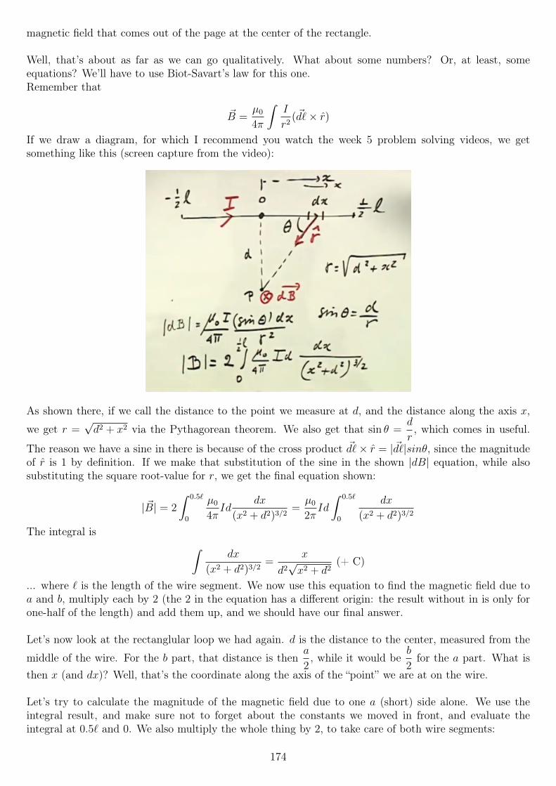
magnetic field that comes out of the page at the center of the rectangle.
Well, that’s about as far as we can go qualitatively. What about some numbers? Or, at least, someequations? We’ll have to use Biot-Savart’s law for this one.Remember that
~B =µ0
4π
∫I
r2(~d`× r)
If we draw a diagram, for which I recommend you watch the week 5 problem solving videos, we getsomething like this (screen capture from the video):
As shown there, if we call the distance to the point we measure at d, and the distance along the axis x,
we get r =√d2 + x2 via the Pythagorean theorem. We also get that sin θ =
d
r, which comes in useful.
The reason we have a sine in there is because of the cross product ~d`× r = |~d`|sinθ, since the magnitudeof r is 1 by definition. If we make that substitution of the sine in the shown |dB| equation, while alsosubstituting the square root-value for r, we get the final equation shown:
| ~B| = 2
∫ 0.5`
0
µ0
4πId
dx
(x2 + d2)3/2=µ0
2πId
∫ 0.5`
0
dx
(x2 + d2)3/2
The integral is ∫dx
(x2 + d2)3/2=
x
d2√x2 + d2
(+ C)
... where ` is the length of the wire segment. We now use this equation to find the magnetic field due toa and b, multiply each by 2 (the 2 in the equation has a different origin: the result without in is only forone-half of the length) and add them up, and we should have our final answer.
Let’s now look at the rectanglular loop we had again. d is the distance to the center, measured from the
middle of the wire. For the b part, that distance is thena
2, while it would be
b
2for the a part. What is
then x (and dx)? Well, that’s the coordinate along the axis of the “point” we are at on the wire.
Let’s try to calculate the magnitude of the magnetic field due to one a (short) side alone. We use theintegral result, and make sure not to forget about the constants we moved in front, and evaluate theintegral at 0.5` and 0. We also multiply the whole thing by 2, to take care of both wire segments:
174
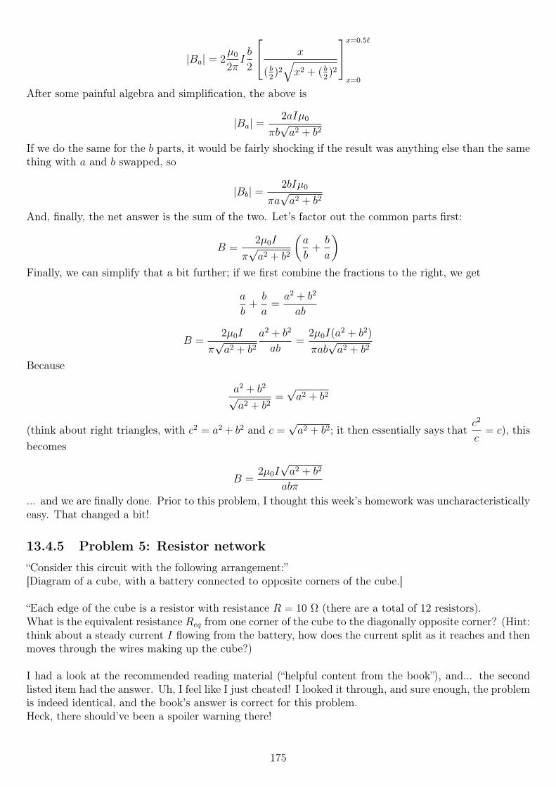
|Ba| = 2µ0
2πIb
2
x
( b2)2
√x2 + ( b
2)2
x=0.5`
x=0
After some painful algebra and simplification, the above is
|Ba| =2aIµ0
πb√a2 + b2
If we do the same for the b parts, it would be fairly shocking if the result was anything else than the samething with a and b swapped, so
|Bb| =2bIµ0
πa√a2 + b2
And, finally, the net answer is the sum of the two. Let’s factor out the common parts first:
B =2µ0I
π√a2 + b2
(a
b+b
a
)Finally, we can simplify that a bit further; if we first combine the fractions to the right, we get
a
b+b
a=a2 + b2
ab
B =2µ0I
π√a2 + b2
a2 + b2
ab=
2µ0I(a2 + b2)
πab√a2 + b2
Because
a2 + b2
√a2 + b2
=√a2 + b2
(think about right triangles, with c2 = a2 + b2 and c =√a2 + b2; it then essentially says that
c2
c= c), this
becomes
B =2µ0I√a2 + b2
abπ
... and we are finally done. Prior to this problem, I thought this week’s homework was uncharacteristicallyeasy. That changed a bit!
13.4.5 Problem 5: Resistor network
“Consider this circuit with the following arrangement:”[Diagram of a cube, with a battery connected to opposite corners of the cube.]
“Each edge of the cube is a resistor with resistance R = 10 Ω (there are a total of 12 resistors).What is the equivalent resistance Req from one corner of the cube to the diagonally opposite corner? (Hint:think about a steady current I flowing from the battery, how does the current split as it reaches and thenmoves through the wires making up the cube?)
I had a look at the recommended reading material (“helpful content from the book”), and... the secondlisted item had the answer. Uh, I feel like I just cheated! I looked it through, and sure enough, the problemis indeed identical, and the book’s answer is correct for this problem.Heck, there should’ve been a spoiler warning there!
175
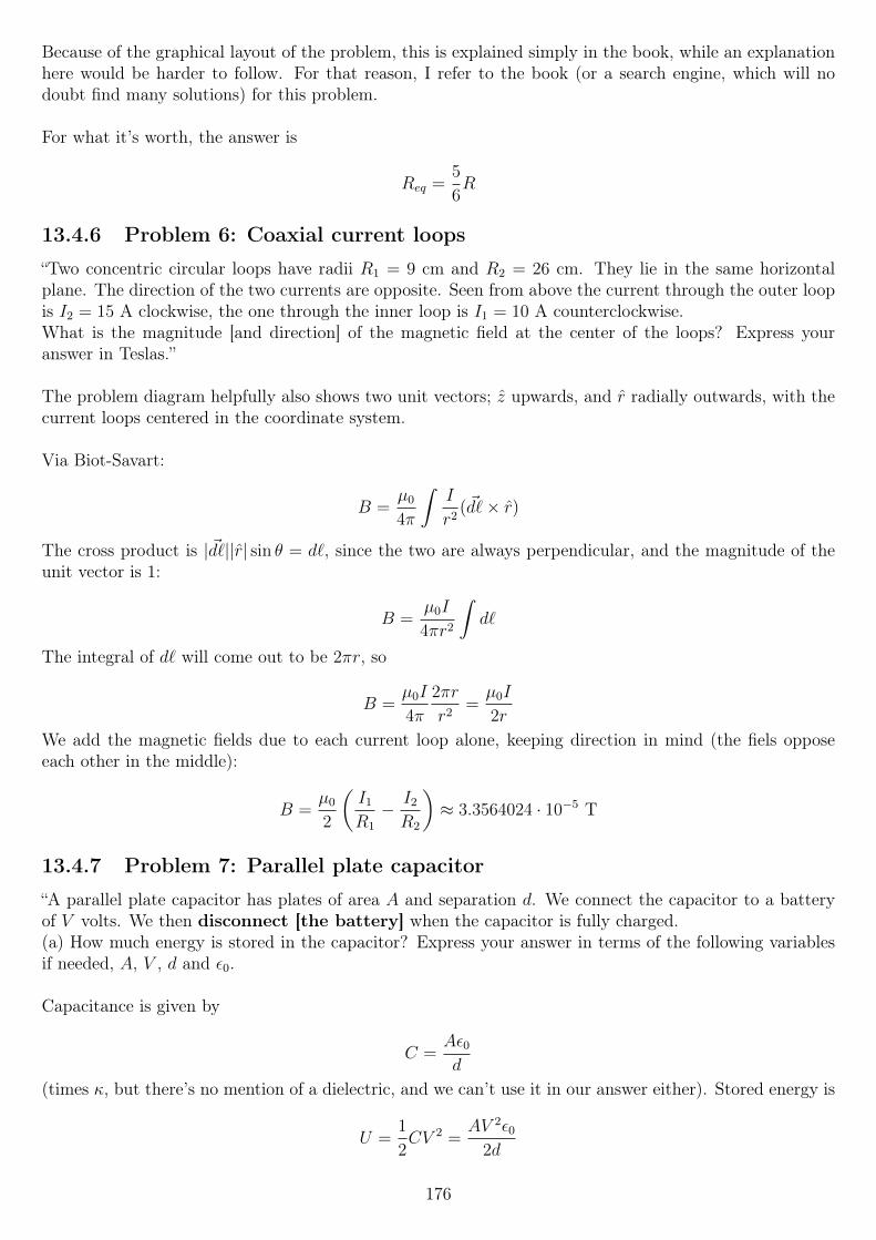
Because of the graphical layout of the problem, this is explained simply in the book, while an explanationhere would be harder to follow. For that reason, I refer to the book (or a search engine, which will nodoubt find many solutions) for this problem.
For what it’s worth, the answer is
Req =5
6R
13.4.6 Problem 6: Coaxial current loops
“Two concentric circular loops have radii R1 = 9 cm and R2 = 26 cm. They lie in the same horizontalplane. The direction of the two currents are opposite. Seen from above the current through the outer loopis I2 = 15 A clockwise, the one through the inner loop is I1 = 10 A counterclockwise.What is the magnitude [and direction] of the magnetic field at the center of the loops? Express youranswer in Teslas.”
The problem diagram helpfully also shows two unit vectors; z upwards, and r radially outwards, with thecurrent loops centered in the coordinate system.
Via Biot-Savart:
B =µ0
4π
∫I
r2(~d`× r)
The cross product is |~d`||r| sin θ = d`, since the two are always perpendicular, and the magnitude of theunit vector is 1:
B =µ0I
4πr2
∫d`
The integral of d` will come out to be 2πr, so
B =µ0I
4π
2πr
r2=µ0I
2r
We add the magnetic fields due to each current loop alone, keeping direction in mind (the fiels opposeeach other in the middle):
B =µ0
2
(I1
R1
− I2
R2
)≈ 3.3564024 · 10−5 T
13.4.7 Problem 7: Parallel plate capacitor
“A parallel plate capacitor has plates of area A and separation d. We connect the capacitor to a batteryof V volts. We then disconnect [the battery] when the capacitor is fully charged.(a) How much energy is stored in the capacitor? Express your answer in terms of the following variablesif needed, A, V , d and ε0.
Capacitance is given by
C =Aε0d
(times κ, but there’s no mention of a dielectric, and we can’t use it in our answer either). Stored energy is
U =1
2CV 2 =
AV 2ε02d
176
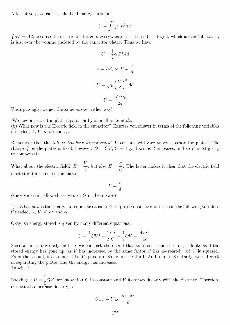
Alternatively, we can use the field energy formula:
U =
∫1
2ε0E
2dV∫dV = Ad, because the electric field is zero everywhere else. Thus the integral, which is over “all space”,
is just over the volume enclosed by the capacitor plates. Thus we have
U =1
2ε0E
2Ad
V = Ed, so E =V
d
U =1
2ε0
(V
d
)2
Ad
U =AV 2ε0
2d
Unsurprisingly, we get the same answer either way!
“We now increase the plate separation by a small amount dz.(b) What now is the Electric field in the capacitor? Express you answer in terms of the following variablesif needed, A, V , d, dz and ε0.
Remember that the battery has been disconnected ! V can and will vary as we separate the plates! Thecharge Q on the plates is fixed, however. Q = CV ; C will go down as d increases, and so V must go upto compensate.
What about the electric field? E =V
d, but also E =
σ
ε0. The latter makes it clear that the electric field
must stay the same, so the answer is
E =V
d
(since we aren’t allowed to use σ or Q in the answer).
“(c) What now is the energy stored in the capacitor? Express you answer in terms of the following variablesif needed, A, V , d, dz and ε0.
Okay; so energy stored is given by many different equations:
U =1
2CV 2 =
1
2
Q2
C=
1
2QV =
AV 2ε02d
Since all must obviously be true, we can pick the one(s) that suits us. From the first, it looks as if thestored energy has gone up, as V has increased by the same factor C has decreased, but V is squared.From the second, it also looks like it’s gone up. Same for the third. And fourth. So clearly, we did workin separating the plates, and the energy has increased.To what?
Looking at U =1
2QV , we know that Q in constant and V increases linearly with the distance. Therefore
U must also increase linearly, so
Unew = Uold ·d+ dz
d
177
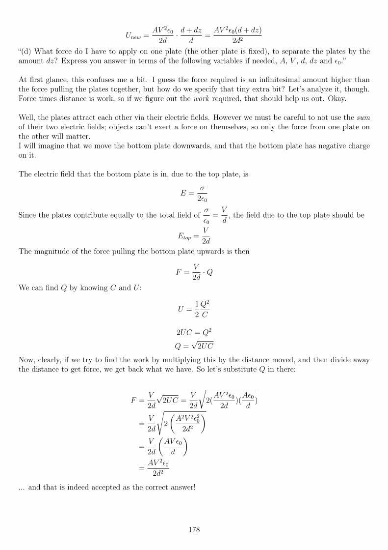
Unew =AV 2ε0
2d· d+ dz
d=AV 2ε0(d+ dz)
2d2
“(d) What force do I have to apply on one plate (the other plate is fixed), to separate the plates by theamount dz? Express you answer in terms of the following variables if needed, A, V , d, dz and ε0.”
At first glance, this confuses me a bit. I guess the force required is an infinitesimal amount higher thanthe force pulling the plates together, but how do we specify that tiny extra bit? Let’s analyze it, though.Force times distance is work, so if we figure out the work required, that should help us out. Okay.
Well, the plates attract each other via their electric fields. However we must be careful to not use the sumof their two electric fields; objects can’t exert a force on themselves, so only the force from one plate onthe other will matter.I will imagine that we move the bottom plate downwards, and that the bottom plate has negative chargeon it.
The electric field that the bottom plate is in, due to the top plate, is
E =σ
2ε0
Since the plates contribute equally to the total field ofσ
ε0=V
d, the field due to the top plate should be
Etop =V
2d
The magnitude of the force pulling the bottom plate upwards is then
F =V
2d·Q
We can find Q by knowing C and U :
U =1
2
Q2
C
2UC = Q2
Q =√
2UC
Now, clearly, if we try to find the work by multiplying this by the distance moved, and then divide awaythe distance to get force, we get back what we have. So let’s substitute Q in there:
F =V
2d
√2UC =
V
2d
√2(AV 2ε0
2d)(Aε0d
)
=V
2d
√2
(A2V 2ε20
2d2
)=V
2d
(AV ε0d
)=AV 2ε0
2d2
... and that is indeed accepted as the correct answer!
178
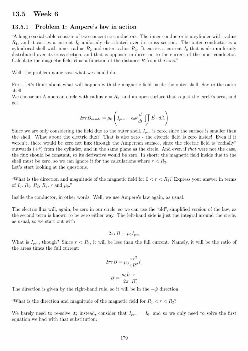
13.5 Week 6
13.5.1 Problem 1: Ampere’s law in action
“A long coaxial cable consists of two concentric conductors. The inner conductor is a cylinder with radiusR1, and it carries a current I0 uniformly distributed over its cross section. The outer conductor is acylindrical shell with inner radius R2 and outer radius R3. It carries a current I0 that is also uniformlydistributed over its cross section, and that is opposite in direction to the current of the inner conductor.Calculate the magnetic field ~B as a function of the distance R from the axis.”
Well, the problem name says what we should do.
First, let’s think about what will happen with the magnetic field inside the outer shell, due to the outershell.We choose an Amperean circle with radius r = R2, and an open surface that is just the circle’s area, andget
2πrBinside = µ0
(Ipen + ε0κ
d
dt
x
S
~E · ~dA
)Since we are only considering the field due to the outer shell, Ipen is zero, since the surface is smaller thanthe shell. What about the electric flux? That is also zero - the electric field is zero inside! Even if itweren’t, there would be zero net flux through the Amperean surface, since the electric field is “radially”outwards (+r) from the cylinder, and in the same plane as the circle. And even if that were not the case,the flux should be constant, so its derivative would be zero. In short: the magnetic field inside due to theshell must be zero, so we can ignore it for the calculations where r < R2.Let’s start looking at the questions.
“What is the direction and magnitude of the magnetic field for 0 < r < R1? Express your answer in termsof I0, R1, R2, R3, r and µ0.”
Inside the conductor, in other words. Well, we use Ampere’s law again, as usual.
The electric flux will, again, be zero in our circle, so we can use the “old”, simplified version of the law, asthe second term is known to be zero either way. The left-hand side is just the integral around the circle,as usual, so we start out with
2πrB = µ0Ipen
What is Ipen, though? Since r < R1, it will be less than the full current. Namely, it will be the ratio ofthe areas times the full current:
2πrB = µ0πr2
πR21
I0
B =µ0I0
2π
r
R21
The direction is given by the right-hand rule, so it will be in the +ϕ direction.
“What is the direction and magnitude of the magnetic field for R1 < r < R2?
We barely need to re-solve it; instead, consider that Ipen = I0, and so we only need to solve the firstequation we had with that substitution:
179
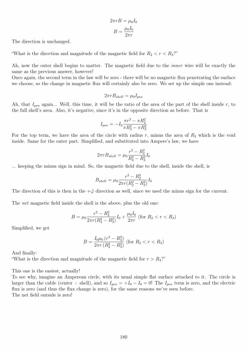
2πrB = µ0I0
B =µ0I0
2πr
The direction is unchanged.
“What is the direction and magnitude of the magnetic field for R2 < r < R3?”
Ah, now the outer shell begins to matter. The magnetic field due to the inner wire will be exactly thesame as the previous answer, however!Once again, the second term in the law will be zero - there will be no magnetic flux penetrating the surfacewe choose, so the change in magnetic flux will certainly also be zero. We set up the simple one instead:
2πrBshell = µ0Ipen
Ah, that Ipen again... Well, this time, it will be the ratio of the area of the part of the shell inside r, tothe full shell’s area. Also, it’s negative, since it’s in the opposite direction as before. That is
Ipen = −I0πr2 − πR2
2
πR23 − πR2
2
For the top term, we have the area of the circle with radius r, minus the area of R2 which is the voidinside. Same for the outer part. Simplified, and substituted into Ampere’s law, we have
2πrBshell = µ0r2 −R2
2
R22 −R2
3
I0
... keeping the minus sign in mind. So, the magnetic field due to the shell, inside the shell, is
Bshell = µ0r2 −R2
2
2πr(R22 −R2
3)I0
The direction of this is then in the +ϕ direction as well, since we used the minus sign for the current.
The net magnetic field inside the shell is the above, plus the old one:
B = µ0r2 −R2
2
2πr(R22 −R2
3)I0 +
µ0I0
2πr(for R2 < r < R3)
Simplified, we get
B =I0µ0 (r2 −R2
3)
2πr (R22 −R2
3)(for R2 < r < R3)
And finally:“What is the direction and magnitude of the magnetic field for r > R3?”
This one is the easiest, actually!To see why, imagine an Amperean circle, with its usual simple flat surface attached to it. The circle islarger than the cable (center + shell), and so Ipen = +I0 − I0 = 0! The Ipen term is zero, and the electricflux is zero (and thus the flux change is zero), for the same reasons we’ve seen before.The net field outside is zero!
180
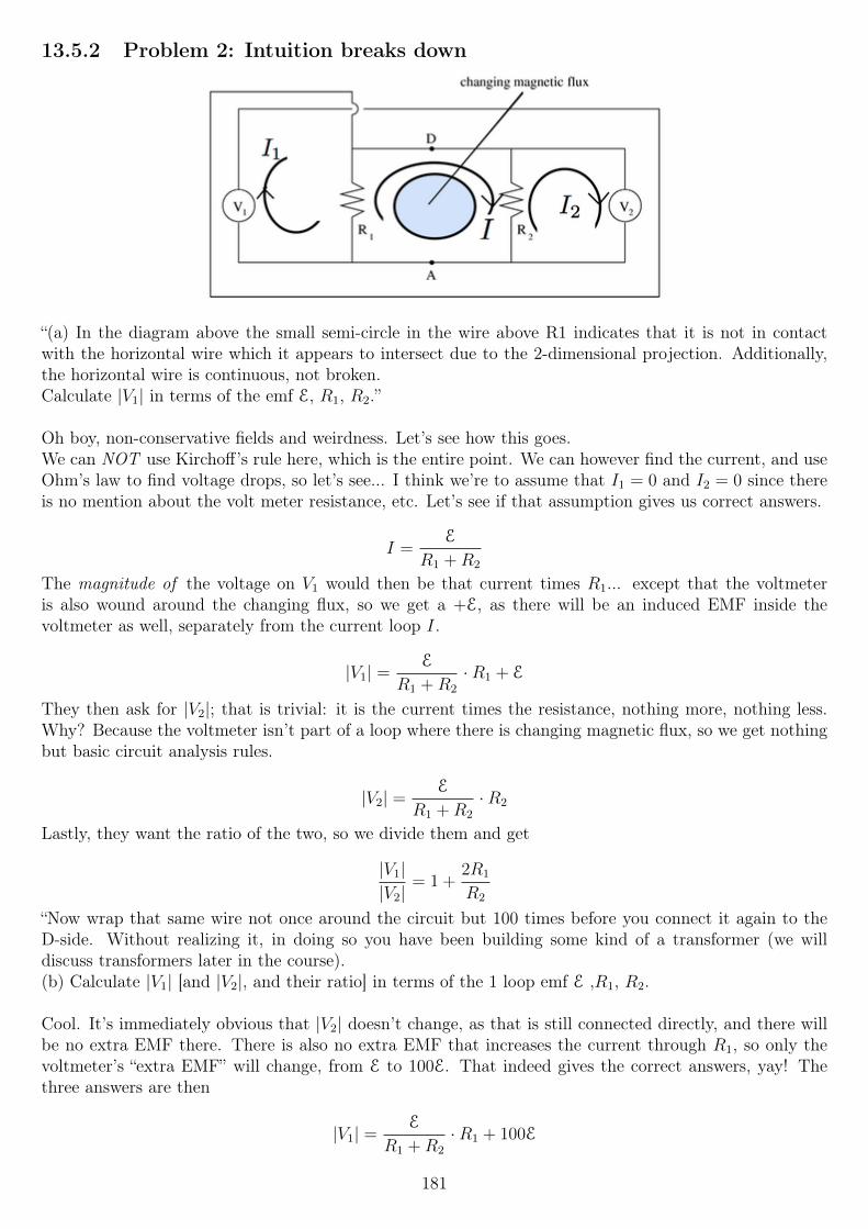
13.5.2 Problem 2: Intuition breaks down
“(a) In the diagram above the small semi-circle in the wire above R1 indicates that it is not in contactwith the horizontal wire which it appears to intersect due to the 2-dimensional projection. Additionally,the horizontal wire is continuous, not broken.Calculate |V1| in terms of the emf E, R1, R2.”
Oh boy, non-conservative fields and weirdness. Let’s see how this goes.We can NOT use Kirchoff’s rule here, which is the entire point. We can however find the current, and useOhm’s law to find voltage drops, so let’s see... I think we’re to assume that I1 = 0 and I2 = 0 since thereis no mention about the volt meter resistance, etc. Let’s see if that assumption gives us correct answers.
I =E
R1 +R2
The magnitude of the voltage on V1 would then be that current times R1... except that the voltmeteris also wound around the changing flux, so we get a +E, as there will be an induced EMF inside thevoltmeter as well, separately from the current loop I.
|V1| =E
R1 +R2
·R1 + E
They then ask for |V2|; that is trivial: it is the current times the resistance, nothing more, nothing less.Why? Because the voltmeter isn’t part of a loop where there is changing magnetic flux, so we get nothingbut basic circuit analysis rules.
|V2| =E
R1 +R2
·R2
Lastly, they want the ratio of the two, so we divide them and get
|V1||V2|
= 1 +2R1
R2
“Now wrap that same wire not once around the circuit but 100 times before you connect it again to theD-side. Without realizing it, in doing so you have been building some kind of a transformer (we willdiscuss transformers later in the course).(b) Calculate |V1| [and |V2|, and their ratio] in terms of the 1 loop emf E ,R1, R2.
Cool. It’s immediately obvious that |V2| doesn’t change, as that is still connected directly, and there willbe no extra EMF there. There is also no extra EMF that increases the current through R1, so only thevoltmeter’s “extra EMF” will change, from E to 100E. That indeed gives the correct answers, yay! Thethree answers are then
|V1| =E
R1 +R2
·R1 + 100E
181
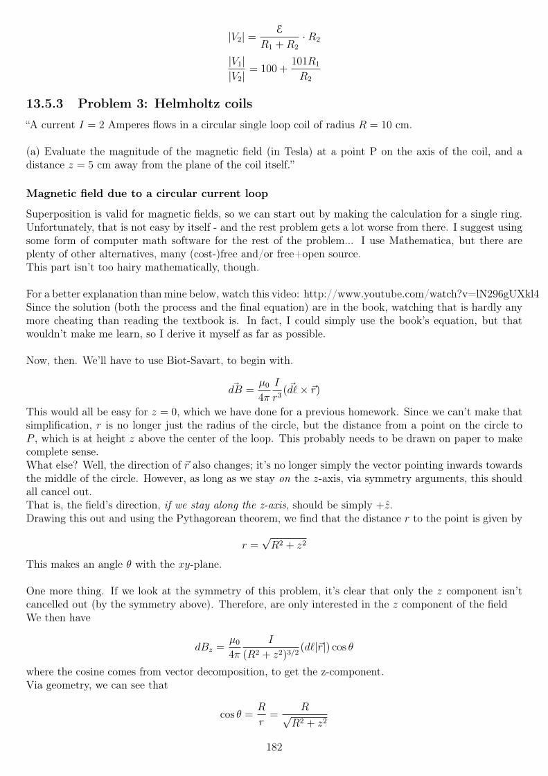
|V2| =E
R1 +R2
·R2
|V1||V2|
= 100 +101R1
R2
13.5.3 Problem 3: Helmholtz coils
“A current I = 2 Amperes flows in a circular single loop coil of radius R = 10 cm.
(a) Evaluate the magnitude of the magnetic field (in Tesla) at a point P on the axis of the coil, and adistance z = 5 cm away from the plane of the coil itself.”
Magnetic field due to a circular current loop
Superposition is valid for magnetic fields, so we can start out by making the calculation for a single ring.Unfortunately, that is not easy by itself - and the rest problem gets a lot worse from there. I suggest usingsome form of computer math software for the rest of the problem... I use Mathematica, but there areplenty of other alternatives, many (cost-)free and/or free+open source.This part isn’t too hairy mathematically, though.
For a better explanation than mine below, watch this video: http://www.youtube.com/watch?v=lN296gUXkl4Since the solution (both the process and the final equation) are in the book, watching that is hardly anymore cheating than reading the textbook is. In fact, I could simply use the book’s equation, but thatwouldn’t make me learn, so I derive it myself as far as possible.
Now, then. We’ll have to use Biot-Savart, to begin with.
~dB =µ0
4π
I
r3(~d`× ~r)
This would all be easy for z = 0, which we have done for a previous homework. Since we can’t make thatsimplification, r is no longer just the radius of the circle, but the distance from a point on the circle toP , which is at height z above the center of the loop. This probably needs to be drawn on paper to makecomplete sense.What else? Well, the direction of ~r also changes; it’s no longer simply the vector pointing inwards towardsthe middle of the circle. However, as long as we stay on the z-axis, via symmetry arguments, this shouldall cancel out.That is, the field’s direction, if we stay along the z-axis, should be simply +z.Drawing this out and using the Pythagorean theorem, we find that the distance r to the point is given by
r =√R2 + z2
This makes an angle θ with the xy-plane.
One more thing. If we look at the symmetry of this problem, it’s clear that only the z component isn’tcancelled out (by the symmetry above). Therefore, are only interested in the z component of the fieldWe then have
dBz =µ0
4π
I
(R2 + z2)3/2(d`|~r|) cos θ
where the cosine comes from vector decomposition, to get the z-component.Via geometry, we can see that
cos θ =R
r=
R√R2 + z2
182
Therefore we have
dBz =µ0
4π
I
(R2 + z2)3/2d`|~r| R√
R2 + z2
dBz =µ0
4π
I
(R2 + z2)3/2d`√R2 + z2
R√R2 + z2
dBz =µ0
4π
IR
(R2 + z2)3/2d`
We can finally integrate that:
Bz =
∫µ0
4π
IR
(R2 + z2)3/2d` =
µ0
4π
IR
(R2 + z2)3/2
∫d`
Bz =µ0
2
IR2
(R2 + z2)3/2
Thus, we can answer part (a) by plugging in the values given.
Two circular loops
“Now consider two N -turn circular coils of radius R, each perpendicular to the axis of symmetry, with
their centers located at z = ± `2. There is a steady current I flowing in the same direction around each
coil, as shown in the figure below.”The image shows a similar situation to what we had, then, but with two coils, above and below z = 0,where the old one was.
“(b) Assuming the N = 100, I = 2 Amperes, R = 10 cm, ` = 2 cm, calculate the magnitude of themagnetic field (in Tesla) at a distance z = 0.5 cm from the midpoint between the centers of the two coils.”
The field due to N loops is simply N times stronger, as each loop simply adds to the rest. (I suppose wecan think of it as integrating over the circle N times, so we integrate from 0 to N · 2π, which then justspits out a factor N .)
With that in mind, and superposition, this part should be easy enough. When using the equation we justderived, the z value is really the distance from the center of the ring, which isn’t at z = 0 in the coordinatesystem any longer. We need to adjust it slighly; same goes for the circle below. I’ll call the top one 1 andthe bottom one 2:
Bz1 =µ0
2
NIR2
(R2 + ( `2− z)2)3/2
Bz2 =µ0
2
NIR2
(R2 + (− `2− z)2)3/2
The sum is then
Bz =µ0NIR
2
2
(1
(R2 + ( `2− z)2)3/2
+1
(R2 + (− `2− z)2)3/2
)If we just plug in the numbers given now, and sum the two answers, we get the answer they want.
“(c) Evaluate the first derivative with respect to z of the magnetic field calculated in part (b) using thesame values for the parameters. Express your answer in Tesla per meter.”
183
Goodness, this is why I recommend using math software. I’m not differentiating that - the z is hiddeninside two exponents, in the denominator of a fraction - and they want the second derivative later on, too!
The first derivative is given by
dBz
dz= 4µ0NIR
2
(6(l − 2z)
((l − 2z)2 + 4R2)5/2− 6(l + 2z)
((l + 2z)2 + 4R2)5/2
)The second derivative is given by
d2Bz
dz2= 4µ0NIR
2
(60(l + 2z)2
((l + 2z)2 + 4R2)7/2− 12
((l + 2z)2 + 4R2)5/2− 12
((l − 2z)2 + 4R2)5/2+
60(l − 2z)2
((l − 2z)2 + 4R2)7/2
)
What a friggin’ nightmare! My heart goes out to the students that solved this on their own. (I just noticedthat these equations are in the book. I’m sure some worked it out manually, though.)Once again, though, plugging in the values gives the correct answer.
The rest of the questions are for the same problem, with R = l = 10 cm and z = 0, so we just plug in thenumbers to solve those, the point being that the first and second derivatives are both exactly zero in thatcase.
13.5.4 Problem 4: Spinning loop in a magnetic field
“A square loop (side L) spins with angular frequency ω in field of strength B. It is hooked to a load R.(a) Write an expression for current I(t) in terms of B, L, R, ω and t.”
Well, we can find the EMF using Faraday’s law. It’s the negative of the change in magnetic flux throughthe loop. So let’s first find the flux through the loop; we have a planar surface, and a uniform, constantmagnetic field of strength B (since there is no other information). Magnetic flux is B-field strength timesarea, so
ΦB = L2B cos θ
... where θ is the angle between B and the normal to the surface.Since we are rotating the loop, θ changes with time according to the angular frequency ω:
θ = θ0 + ωt
We can choose θ0 = 0 to simplify, so we do that, and then differentiate and negate it to find the EMF:
ΦB = L2B cosωt
dΦB
dt= −L2Bω sinωt
E(t) = −dΦB
dt= L2Bω sinωt
The current is then this, divided by the resistance R:
I(t) =L2Bω sinωt
R
“(b) How much work is done by the generator per revolution? Express your answer in terms of B,L,R andω (enter omega for ω).”
184
The work done will be equal to the heat dissipated in the resistor, so we could integrate that power overthe time of one rotation.
ω =2π
T, so T =
2π
ω
The power is given by I2R:
P (t) =
(L2Bω sinωt
R
)2
R =L4B2ω2sin2ωt
R
The work is the integral, then, from t = 0 to t = T :
W =
∫ T
0
L4B2ω2sin2ωt
R=L4B2ω2
R
∫ T
0
sin2ωt
When we integrate the sine, and substitute T =2π
ω, the result of the integral is simply
π
ω, so we get:
W =L4B2ωπ
R
“(c) To make it twice as hard to turn (twice as much work), what factor would you have to multiply theresistance R?”
It’s clear from the equation just above that, since no other variable is dependent or R, we simply need to
halve R, so the answer is1
2.
13.5.5 Problem 5: Loop in a magnetic field
“A rectangular wire loop of dimensions a× b, with a = 3.5 cm and b = 4.5 cm, is pulled parallel to side aat a constant speed v = 4.3 m/sec into a region where the magnetic field, | ~B| = 0.125 T, is uniform andperpendicular to the loop. The loop enters the magnetic field at time t = 0.(a) Calculate the rate at which the magnetic flux through the loop is changing. Express your answer in
Tesla · m2
sec.
I would’ve preferred an illustration, but all right. I assume that “pulled parallel to side a” means there issome external force in the same direction as the line a is in. That makes the area of the loop exposed tothe magnetic field ba(t). The flux is
ΦB = b a(t)B
The rate of change is then
dΦB
dt= b
da
dtB = bvB
“(b) What is the magnitude of the induced EMF at time t?”
This confuses me, since they are expecting a numerical answer... The magnitude of the EMF is the same asthe first answer, though, which is accepted. I suppose the point they want to make is that it is independentupon t? However, as soon as the loop has entered the magnetic field fully, surely the flux would becomeconstant.
185
13.5.6 Problem 6: Electrodynamic tether
“A L = 3 mile long conducting cable tethers a satellite to the International Space Station. The Cablemoves through the Earth’ magnetic field of about B = 0.02 Gauss at a speed of v = 8 km/sec. The cablepoints radially from the Space Station to the satellite. The ISS moves Eastwards and the magnetic fieldis Northward.What is the potential difference between the two ends of the tether?”
This is really nothing more than a simple motional EMF problem. Unless I’m missing something (despitehaving the answer right), most of the work is in the unit conversion, really. Most of this solution is restat-ing facts about motional EMF.
Say we have a conductive bar moving rightwards, in a magnetic field going into the page. The free electronsin the bar experience a magnetic force upwards:
~FB = q(~v × ~B)
Positive charge gathers closer to the top, and negative charge towards the bottom.This produces an electric field inside the bar, from positive to negative as usual, which forces positivecharges down, and negative charges up, with force
~FE = q ~E
In an static situation of constant magnetic field and velocity, we’ll find an equilibrium where the forcesare equal:
q(~v × ~B) = q ~E
~v × ~B = ~E
We evaluate the cross product, which is simply vB, since the angle between them is 90 degrees, so thesin θ term in the cross prodcut is one.
E = vB
Given that the electric field should be constant (since v and B are constant), the potential difference isthen given by V = Ed, where d is the distance, here `
∆V = vB`
Going back to our problem, we can now solve for the potential difference:
∆V = vB` = (8000ms
)(0.02 · 10−4 tesla)(3 miles1609 m1 mile
) = 77.232 V
Which end has the higher potential? If the velocity is eastwards, and the B-field northward, then themagnetic force is “upwards” (outwards from the surface), so the positive charge gathers at the far end, sothe potential is highest at the end the farthest away from the Earth.
13.5.7 Problem 7: Motor
“A simple motor has N = 250 turns of wire on a coil measuring 12 cm × 4 cm. It’s resistance is R = 10ohms. The magnetic field is B = 1 tesla.(a) How much current (in Ampere) in the coil is needed to produce a maximum torque of 40 N ·m?”
186
Motors aren’t my strong side - they haven’t been talked about a whole lot in the course, and I didn’t take8.01 prior to this course, so I’m not super-familiar with torque... so I had a look in the suggested reading.The torque τ on the loop is given by
|τ | = IAB
... where A is the area of the loop.
In this case, the current will be given by NI, as the multiple windings simply multiply the torque. So, wehave
|τ | = NIAB
I =|τ |
NAB
Now we just need to stick the numbers in, and find I =100
3= 33.3333 amperes.
“(b) What maximum EMF (in Volts) is needed to drive the motor at 50 Hz if the current is constant?”
Let’s see. There will be an induced EMF due to the changing magnetic flux through the loop, as it rotates.The current through the loop (due to the external source) in the book’s drawing is counterclockwise, solet’s assume that it will be at one instant, just for visualization.What about the induced EMF, in which direction will that one be? In the one that opposes the changein the external flux, which turns out to be in the opposite direction, so the induced EMF will counteractthe external one the power supply provides.
What will the induced EMF be?The flux through the surface is
ΦB = NAB cos θ
Since it rotates, as we’ve done before, we set θ = ωt, and then differentiate the flux, and negate it, to findthe EMF:
dΦB
dt= −NABω sinωt
E = −dΦB
dt= NABω sinωt
The EMF maximum will then occur when sinωt = 1, so the maximum induced EMF will be NABω.ω = 2πf = 2π · (50 Hz) = 100π, so the maximum induced EMF is
E = (250)(4 cm)(12 cm)(1 T)(100π rad/s) ≈ 377 V
Here’s the interesting point. The above is not only the maximum induced EMF, but actually also theanswer to the question.Motors and generators are strongly related. If we think of this motor as a generator, the maximum EMFgenerated at angular frequency ω is the same as the maximum EMF required to turn the motor at thesame angular frequency ω.
I’m still unsure of exactly why this is the case, though. I’m hoping next week’s talk about inductance andphase lag help a bit.
187
13.5.8 Problem 8: Auroral zone
This problem has a very long introduction, with a derivation of the equation used, etc, and several figures.I suggest reading that first!
“... The solar wind ram pressure causes the magnetic field of the earth to terminate at about 10RE on thesunward side of the earth (see figure).The auroral zone is defined by the last field line from the Earth that returns to the Earth. If the fieldof the earth extends no further than 10RE in the sunward direction, at what angle (in degrees) in thepicture above does the last field line that returns to the earth on the sunward side leave the polar regionsof the earth at 1RE, assuming that the fields are always described by r = R0 sin2 θ? In the drawing, thisis equivalent to asking what is the angle with respect to the vertical of a line from the center of the earthto the point that the red curve intersects the light blue circle.”
Admittedly, I first solved this one by graphing it, and will solve it more mathematically below.In polar coordinates, r = 1 gives a circle; if we choose our coordinate system such that RE = 1, this thenrepresents the Earth.The field lines are then plotted by the equation given, r = R0 sin2 θ, with various values for R0. WhenR0 = 10, we get that “last” field line the questions asks about.
When we’ve graphed both on the same plot, we can simply zoom in and read off the angle. Well, almost -polar coordinates define angles as 0 on the +x axis, and so to find the answer - the angle from the verticalaxis, we need to shift it. Additionally, this angle will be in radians, while they requested degrees.Anyhow, I read it off as 0.3975π from the horizontal axis; with the 90 degree =
π
2conversion, and then
from radians to degrees, the answer is approximately(π2− 0.3975π
) 180
π rad≈ 18.45
It turns out the mathematical solution isn’t very much harder. We just set up
RE = 10RE sin2 θ
... since those are the r coordinates where the lines meet, and solve the equation. The solution pops out:
10 sin2 θ = 1
sin2 θ =1
10
sin θ =1√10
θ = arcsin1√10≈ 18.43495
Keep in mind that
sin2 θ = (sin θ)(sin θ)
if that part was unclear.
13.6 Week 7
13.6.1 Problem 1: Magnetic energy of a solenoid
“Compare the total magnetic energy in two solenoids, each with N turns, area A, and current I, but lengthx and 2x. Denote Ux the total magnetic energy in the solenoid with length x, and U2x the one in the
188
solenoid with length 2x. What is U2x/Ux?”
We calculated the magnetic field energy density back in this week’s lecture notes, and since it featured afairly ugly integral, a circuit to solve etc., I won’t redo it all here, as I would if it were simpler.Instead, we found the inductance L of a solenoid and the field energy density U to be
L = πr2N2
`µ0
U =B2
2µ0
The B-field inside the solenoid can be derived relatively easily using Ampere’s law, which we have donepreviously (week 5), so I will do the quick-and-dirty version here. There is no displacement current throughthe Amperean surfacae we choose, so we can use the simplified Ampere’s law:∮
~B · ~d` = µ0Ipen
Ba = µ0IaN
`
B = µ0IN
`
We then want to square that, and then divide by 2µ0, to find the energy density:
U =1
2µ0
(µ0IN
`
)2
=µ0I
2N2
2`2
The ` we have used is the length of the solenoid, which then is to be x or 2x.
Since the B-field is assumed to be constant inside a solenoid, and 0 outside, the total magnetic energy isthe above times the volume, A`, where we substitute in the value for `:
Ux =µ0I
2N2
2x2Ax
U2x =µ0I
2N2
2(2x)2A2x
Finding the ratio U2x/Ux, we first get rid of all the terms that are the same in both expressions, and get
U2x
Ux=
A2x
(2x)2
/Axx2
=A2x
4x2· x
2
Ax=
2Ax3
4Ax3
With all that cancels, we find
U2x
Ux=
1
2
Since the total energy is proportional to1
`(the Ux = ... equation above), this does appear to make sense.
The energy density is proportional to1
`2, but we then multiply that by a ` term to find the total energy.
189
13.6.2 Problem 2: Displacement current
“Consider the process of charging a parallel plate capacitor with circular plates of radius R = 5 cm sepa-rated by a distance d = 0.2 cm. At some time t1, the capacitor is being charged with a current I = 0.035 A.
Consider a point P on the plane which is equally distant from the two plates and is a distance r = 0.068m away from the axis of the capacitor.(a) Calculate the magnitude of the magnetic field (in Tesla) at a point P at time t1 during the charge ofthe capacitor.”We will want to use the (almost) full version of Ampere’s law for this one. (Next week we will finally havethe fully complete version.) ∮
~B · ~d` = µ0
(Ipen + ε0κ
d
dt
x~E · ~dA
)We choose our Amperean loop as a circle with radius r, concentric with the capacitor plates, and centeredin the distance between the plates as mentioned. We must then attatched an open surface to our closedloop (the circle), and we choose a flat surface in the plate of the circle (think of it as the circle’s area) forsimplicity.
The left-side integral becomes B2πr; Ipen = 0 since the surface is in in mid-air and no real current can passthrough it. The rate of change of the electric flux through the surface will however be nonzero! Replacing~E with its magnitude
Q
κε0πR2and the area the flux goes through by πR2 (capital R! r > R, so the flux
only goes through part of πr2!) we get, with all our changes:
B2πr = µ0ε0κd
dt
(Q
κε0πR2πR2
)The dot product inside the integral turns into a regular multiplication, and the integral is trivial since theE-field is uniform, so all infinitesimal products ~E · ~dA are the same.In taking the time derivative, we find that the only non-constant is Q, which will change over time, so
d
dt
(Q
κε0πR2πR2
)=
πR2
κε0πR2
d
dt(Q) =
1
κε0
dQ
dt=
I
κε0
where I is the current in the wire to (or from) the capacitor, not Ipen which we established was zero.Putting it all together and solving for B:
B2πr = µ0ε0κI
κε0
B =µ0I
2πr
For the values given,
B =(4π)(10−7)(0.035)
2π0.068=
2(10−7)(0.035)
0.068≈ 1.0294 · 10−7 T
13.6.3 Problem 3: RL circuit
“Consider a circuit with an RL series with L = 0.09 H and R = 0.05 Ohm. At t = 0 the circuit is connectedto a battery which provides V0 = 12 V.(a) How long does it take to the current to equal a fraction 0.95 of the steady state current?”
We could set up and solve a differential equation, but there’s little in point in doing that, since we foundthe solution already in this week’s lectures. The current is governed by the equation
190
I(t) =V
R
(1− exp
(−RtL
))The steady state current is then just V
R, as the inductance will have no effect for the steady state.
Thus, we want to find when the first equation equals 0.95 times the second:
V
R
(1− exp
(−RtL
))= 0.95
V
R
1− exp
(−RtL
)= 0.95
− exp
(−RtL
)= −0.05
exp
(−RtL
)= 0.05
−RtL
= ln 0.05
t = −LR
ln 0.05
For the values given, t ≈ 5.392 seconds.
“(b) What is the energy stored (in Joules) in the magnetic field when the current equals a fraction 0.95 ofthe steady state current?”
The energy stored is given by
U =1
2LI2
Since I at that time equals 0.95VR,
U =1
2L
(0.95
V
R
)2
≈ 2339.28 J
“(c) What is the total energy delivered (in Joules) by the battery up to the time t found in part (a)?How much energy (in Joules) has been dissipated in the resistor?”
The total energy delivered is the energy stored (in the ideal inductor) plus the energy burned in the resistorup to that time, the integral of I2R from t = 0 to t = (answer a).
∫ 5.392318
0
I2R dt =
∫ 5.392318
0
V 2
R2
(1− exp
(−RtL
))2
R dt =V 2
R
∫ 5.392318
0
(1− exp
(−RtL
))2
dt
I didn’t see an easy way to get that integral down to something simple, so I solved it with Mathematica.Simplified, and keeping the V 2
Rin front in mind, I found
−V 2(L(e−
2RTL − 4e−
RTL + 3
)− 2RT
)2R2
with T being the upper integration limit; T = 5.392318 for this problem. Putting the values in there, wefind that the energy burned is ≈ 8265.796 joules.That is then the answer for question (c2), while the answer to (c1) is (b) plus (c2).(The total energy delivered is the energy stored plus the energy burned in the resistor.)
191
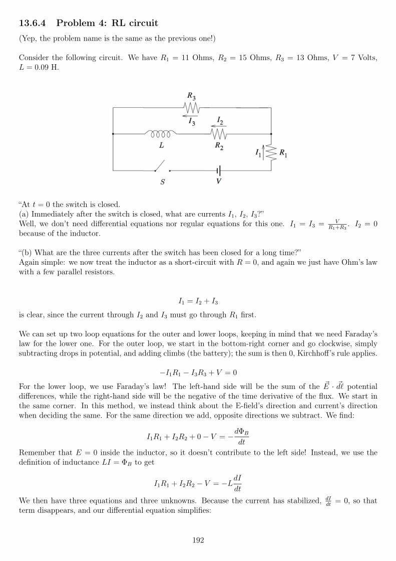
13.6.4 Problem 4: RL circuit
(Yep, the problem name is the same as the previous one!)
Consider the following circuit. We have R1 = 11 Ohms, R2 = 15 Ohms, R3 = 13 Ohms, V = 7 Volts,L = 0.09 H.
“At t = 0 the switch is closed.(a) Immediately after the switch is closed, what are currents I1, I2, I3?”Well, we don’t need differential equations nor regular equations for this one. I1 = I3 = V
R1+R3. I2 = 0
because of the inductor.
“(b) What are the three currents after the switch has been closed for a long time?”Again simple: we now treat the inductor as a short-circuit with R = 0, and again we just have Ohm’s lawwith a few parallel resistors.
I1 = I2 + I3
is clear, since the current through I2 and I3 must go through R1 first.
We can set up two loop equations for the outer and lower loops, keeping in mind that we need Faraday’slaw for the lower one. For the outer loop, we start in the bottom-right corner and go clockwise, simplysubtracting drops in potential, and adding climbs (the battery); the sum is then 0, Kirchhoff’s rule applies.
−I1R1 − I3R3 + V = 0
For the lower loop, we use Faraday’s law! The left-hand side will be the sum of the ~E · ~d` potentialdifferences, while the right-hand side will be the negative of the time derivative of the flux. We start inthe same corner. In this method, we instead think about the E-field’s direction and current’s directionwhen deciding the same. For the same direction we add, opposite directions we subtract. We find:
I1R1 + I2R2 + 0− V = −dΦB
dt
Remember that E = 0 inside the inductor, so it doesn’t contribute to the left side! Instead, we use thedefinition of inductance LI = ΦB to get
I1R1 + I2R2 − V = −LdIdt
We then have three equations and three unknowns. Because the current has stabilized, dIdt
= 0, so thatterm disappears, and our differential equation simplifies:
192
I1 = I2 + I3
−I1R1 − I3R3 + V = 0
I1R1 + I2R2 − V = 0
Solving the system, we get (I used Mathematica):
I1 = I2 + I3
I2 =R3V
R1R2 +R1R3 +R2R3
I3 =R2V
R1R2 +R1R3 +R2R3
“The switch is now opened again.(c) What are the three currents after the switch is reopened?”
The question is slightly unclear, but the answers work if we calculate the answer for t = 0+ where it wasopened at t = 0. That is, an infinitesimal amount of time later, so that the inductor current is unchanged.
Note that the circuit changes. S, V and R1 are now disconnected/left open, so the circuit is now L, R2
and R3 in series. Thus I3 = −I2, with I2 unchanged from our answer above.I1 = 0, since it is disconnected.
13.6.5 Problem 5: Opening a switch on an RL circuit
Even more RL circuits!
“The LR circuit shown in the figure contains a resistor R1 and an inductance L in series with a battery ofemf E0 = V0. The switch S is initially closed. At t = 0, the switch S is opened, so that an additional verylarge resistance R2 (with R2 R1) is now in series with the other elements.
(a) If the switch has been closed for a long time before t = 0, what is the steady current I0 in the circuit?Express your answer in terms of, if appropriate, V0, R1, R2 and L.”
Well, that part’s crazy easy. I =V0
R1
, since everything else is a short circuit.
“(b) While this current I0 is flowing, at time t = 0, the switch S is opened. Write the differential equationfor I(t) that describes the behavior of the circuit at times t > 0. Solve this equation (by integration) forI(t) under the approximation that V0 = 0. (Assume that the battery emf is negligible compared to thetotal emf around the circuit for times just after the switch is opened.)Express your answer in terms of the initial current I0, R1, R2, t and L.”
Well, that’s clearly a lot harder! What the problem means is then that V0 is replaced by a short circuit,while the switch of R = 0 is replaced by the resistance R2. So the circuit is R1, R2 and L all in series,with nothing else to worry about.I would normally just apply the solution to the differential equation directly, but since they insist...Starting at the bottom-right again (why not?), applying Faraday’s law; leftside closed line integral, rightside change in flux:
IR2 + IR1 = −LdIdt
Not having taken a differential equations class, hmm... Solve by integration, they say. I’m not sure howto do that, and it’d feel a bit like cheating to just skip to the known solution, so I’ll attempt the method
193

taught in 6.002x (“circuits and electronics”). First, we try write it in a different form. We set R = R1 +R2,to simplify things.
−LR
dI
dt− I = 0
First, we find the particular solution, which is any solution that satisfies the equation. If we choose I = 0,that works, so Ip = 0.
For the homogeneous solution, we need a function such that the derivative of Ih is a constant LR
timesitself. The exponential function has this property, so we guess (yes, really) that might be a solution, onlythat we have two unknown coefficients. We choose Ih = Aebt:
L
R
dIhdt
+ Ih = 0
L
R
d
dt
(Aebt
)+ Aebt = 0
L
RAbebt + Aebt = 0
We can divide out Aebt at this point:
L
Rb+ 1 = 0
We can now find b:
L
Rb = −1
b = −RL
Well, that looks familiar.The answer to the differential equation is the sum of the particular and homogeneous solutions, we we addthe two. However, our particular solution was 0, so the answer is just the homogeneous solution:
I(t) = A exp
(−RLt
)(using exp(x) = ex notation, to make it readable)We can find the value of A by substituting an initial condition, I(0) = V0
R(by analysis of the circuit), so
we substitute in that value for I and t = 0:
A =V0
R
The exponential turns into 1, so we find the answer at once. The full solution, with A and b known, isthen
I(t) =V0
Rexp
(−RLt
)... which we really knew already, having seen the answer in lecture. At least now we have derived itourselves, too.
The task was to express this answer, using I0 for the initial current, I0 = V0R
= V0R1+R2
(remember that weset R = R1 +R2 earlier):
I0 exp
(−(R1 +R2
L
)t
)194
“(c) Using your results from part b), find the value of the total emf around the circuit (which from Fara-day’s law is −LdI/dt) just after the switch is opened. Express your answer in terms of, if required, V0,R1, R2 and L.”
Well, I suppose we should differentiate the above (since we want to know dIdt
and we know I), and multiplyit by −L, then.
d
dtI0 exp
(−(R1 +R2
L
)t
)= −I0(R1 +R2)
Lexp
(−(R1 +R2
L
)t
)The EMF is then the above times −L, so∑
E = I0(R1 +R2) exp
(−(R1 +R2
L
)t
)The answer does make intuitive sense - the current running times the total resistance ought to equal thetotal EMF!At t = 0, the above simplifies down to ∑
E = I0(R1 +R2)
Time to be careful! I originally substituted in I0 = V0R1+R2
and got∑
E = V0, several times over. However,R2 was just added - the circuit hasn’t had time to react to that, yet. So instead,
I0 =V0
R1∑E =
V0
R1
(R1 +R2) = V0 +V0R2
R1
= V0
(1 +
R2
R1
)“How reasonable is your assumption in part b) that V0 could be ignored for times just after the switch isopened?”Well, considering that we got the answer while assuming that, it appears it was a fairly great assumption.
“d) What is the magnitude of the potential drop across the resistor R2 at times t > 0, just after the switchis opened? Express your answers in units of V0 assuming R2 = 100R1.”
It would have to be the current, answer (b), times R2:
VR2 = I0 exp
(−(R1 +R2
L
)t
)=V0
R1
exp
(−(R1 +R2
L
)t
)R2
With R2 = 100R1:
VR2 = 100V0 exp
(−(R1 +R2
L
)t
)The “times t > 0” part is a bit confusing; they are really asking for the value JUST after the switch isopened, i.e. at t = 0+. Thus the exponential term disappears (with t = 0, the whole term becomes 1),and VR2 = 100V0, or, in “units of V0” as they ask for, just 100.
195
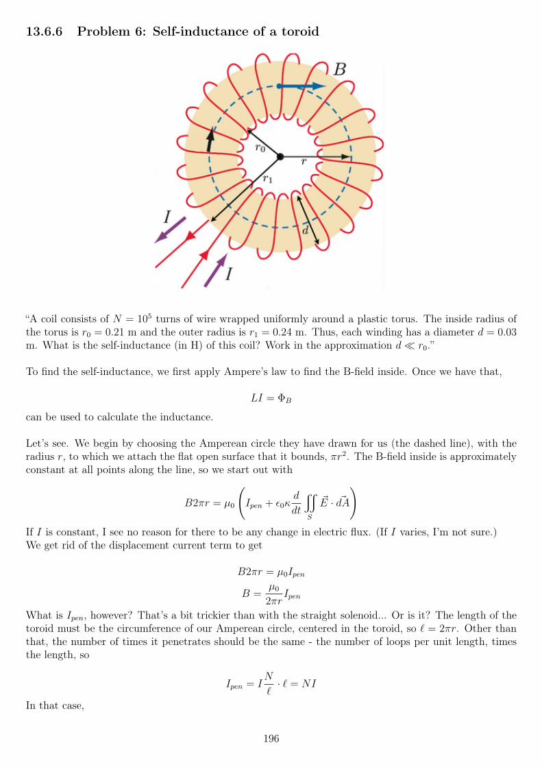
13.6.6 Problem 6: Self-inductance of a toroid
“A coil consists of N = 105 turns of wire wrapped uniformly around a plastic torus. The inside radius ofthe torus is r0 = 0.21 m and the outer radius is r1 = 0.24 m. Thus, each winding has a diameter d = 0.03m. What is the self-inductance (in H) of this coil? Work in the approximation d r0.”
To find the self-inductance, we first apply Ampere’s law to find the B-field inside. Once we have that,
LI = ΦB
can be used to calculate the inductance.
Let’s see. We begin by choosing the Amperean circle they have drawn for us (the dashed line), with theradius r, to which we attach the flat open surface that it bounds, πr2. The B-field inside is approximatelyconstant at all points along the line, so we start out with
B2πr = µ0
(Ipen + ε0κ
d
dt
x
S
~E · ~dA
)If I is constant, I see no reason for there to be any change in electric flux. (If I varies, I’m not sure.)We get rid of the displacement current term to get
B2πr = µ0Ipen
B =µ0
2πrIpen
What is Ipen, however? That’s a bit trickier than with the straight solenoid... Or is it? The length of thetoroid must be the circumference of our Amperean circle, centered in the toroid, so ` = 2πr. Other thanthat, the number of times it penetrates should be the same - the number of loops per unit length, timesthe length, so
Ipen = IN
`· ` = NI
In that case,
196
B =NIµ0
2πrThis turns out to be the correct B-field for a toroid! All right, let’s try to find the flux, so we can find L.
As can be seen above, the B-field is not constant inside, so we really need to integrate this over the area,to find the correct flux.However, we are told to “[w]ork in the approximation d r0”.We can write the B-field as
B =NIµ0
2π(r0 + δ)
Factoring out r0 from the sub-expression in the denominator gives us
B =NIµ0
2πr0(1 + δ/r0)
Now, since δ r0, the δ/r0 term becomes far less than the 1, so we neglect it, and find
B ≈ NIµ0
2πr0
If we use that B-field approximation, we see that in the approximation, it is now constant over the cross-sectional area. We can now find the flux using ΦB = BA, with A being the cross-sectional area, and thenmultiply by the number of windings to find the total flux:
ΦB ≈NIµ0
2πr0
π
(d
2
)2
ΦB ≈NId2µ0
8r0
The inductance is then given by
L =NΦB
I≈ N2d2µ0
8r0
≈ 6.73 H
This result is consistent with that of a a solenoid, which shouldn’t come as a huge shock, seeing that atoroid is essentially a wrapped-up solenoid.We also see that the toroid has a fairly huge inductance, which also shouldn’t be entirely surprising givenits size and 105 windings!
13.6.7 Problem 7: RL circuit
(Yes, really, “RL circuit”!)
“A circuit consists of a self inductor of L = 0.003 H in series with a resistor R1 = 5 Ohm. Parallel to theseis a resistor R2 = 10 Ohm. A battery of V0 = 9 volt is driving the circuit.Current has been running for 10 minutes.
(a) How much energy (in Joules) is now stored in the self-inductor?”
The time constant is less than a millisecond, so the 10 minutes means steady-state has been reached longago.
We treat the inductor as having zero resistance, so the current through it is I1 =V0
R1
. Power stored is
given by U =1
2LI2, so we can easily find the answer using that combination.
197
U =1
2L
(V0
R1
)2
= 0.00486 J
“(b) How much power (in Watt) is then generated by the battery into the circuit? (ignore internal resistanceof the battery).”The inductor no longer draws any power, so the answer is
P =V 2
R1
+V 2
R2
≈ 24.3 W
“The connection to the battery is now broken (so that the battery is not connected to the circuit anymore).
(c) How long will it take (in seconds) for the current through R1 to be reduced by 50%?”We derived the equation for this earlier on in this week’s homework.First, the circuit will change to be R1, R2 and L in series.Second, the current will die out following an exponential decay, given by
I(t) = I0 exp
(−RLt
)If we set that equal to 0.5I0, and solve:
−RLt = ln 0.5
t = −LR
ln 0.5 ≈ 1.386 · 10−4 s
keeping in mind that R = R1 +R2. This also answers (e), since the circuit is now a series circuit.
“(d) How long does it take (in seconds) till the energy stored in the self-inductor has been reduced by50%?”Energy stored is
U =1
2LI2 =
1
2L
(I0 exp
(−RLt
))2
=1
2LI2
0 exp
(−2
R
Lt
)We set that equal to 0.5 times the current stored energy,
1
2LI2
0 :
1
2LI2
0 exp
(−2
R
Lt
)=
1
4LI2
0
exp
(−2
R
Lt
)=
1
2
−2R
Lt = − ln(2)
t =L
R
ln(2)
2≈ 6.93 · 10−5 s
Since we solved part (e) above (same answer as for part c), so we are now done!
13.7 Week 8There’s no homework this week, as the second midterm is next weekend.
198
13.8 Week 9
13.8.1 Problem 1: RC circuit
“In the following circuit V = 9 V, R = 25 Ohm, C = 0.0025 Farad.At t=0 we start charging the capacitor with no charge initially on the capacitor.
(a) Calculate the time t∗ (in seconds) when the potential across the capacitor is V/2.”The circuit is a simple series RC circuit, so I hardly see a need to draw it. The capacitor voltage andcurrent (the latter is the same for the entire circuit, of course) is given by
VC(t) = V
(1− exp
(− t
RC
))I(t) =
V
Rexp
(− t
RC
)To find the answer, we set the potential VC equal to V/2, and solve the exponential for t:
V
(1− exp
(− t
RC
))=V
2
1− exp
(− t
RC
)=
1
2
exp
(− t
RC
)=
1
2
− t
RC= ln
1
2t
RC= ln 2
t
RC= ln 2
t = RC ln 2
We plug our values in, and get t ≈ 0.04332 seconds.
“(b) How much energy (in Joules) has the power supply generated between t = 0 and the time when thepotential across the capacitor reaches V/2?”
There are several ways to solve this. We could find the energy stored in the capacitor (1
2CVC
2) and the
energy dissipated in the resistor (∫ t
0
I2R dt), or we could integrate the power source’s power over time,∫ t
0
V I dt. I’ll choose the later approach, since it should be slightly easier, and it is also the approach that
immediately answers the question, without invoking conservation of energy etc.
We have the integral
E =
∫ t
0
V I(t)dt = V
∫ t
0
V
Rexp
(− t
RC
)dt =
V 2
R
∫ t
0
exp
(− t
RC
)dt
E = V 2C
(1− exp
(− t
RC
)E ≈ 0.101247 J
199
13.8.2 Problem 2: RC circuit
“In the following circuit R1 = 3 Ohm, R2 = 10 Ohm, C = 0.003 Farad, V = 5 Volts.At time t = 0 we connect the power supply to the circuit. At t = 0 the capacitor is uncharged.
(a) What is the time constant τ (in seconds) to charge up the capacitor?”
The time constant is given by τ = RC, where R is the equivalent resistance of the circuit, as seen bythe capacitor. We can find that by shorting out the voltage source (replacing it with ideal wire), andcalculating the resistance by doing series/parallel analysis.
Doing so, we find that all current to the capacitor must go through R1. It can go then either go throughR2 or R1 at the bottom; they are in parallel. So we have
Req = R1 + (R2||R1) = R1 +R2R1
R2 +R1
≈ 5.308 Ω
therefore
τ = ReqC ≈ 5.308 · 0.003 ≈ 0.015924 s
“(b) What is the electric potential over the capacitor when it is fully charged?”
When it is fully charged, the current through the top resistor is zero, and the voltage drop there is zero.Thus the capacitor’s voltage is in parallel with V + VR1, and the two must be equal.
The current through the lower loop is I =V
R1 +R2
=5
13A, and the voltage drop across R1 therefore
15
13volts. Thus
VC = V − VR1 ≈ 3.846 V
“(c) Calculate the current delivered by the power supply as a function of time and evaluate it (in Ampere)for t = 0.6τ , where τ is the value obtained in part (a).”
The function needs to have two parts: one that decays with time, and one that doesn’t.
The latter must either be a constant5
13, the current when the capacitor is fully charged (see (d) below),
or move up to that value as time passes.
It turns out that the two parts are the5
13and the capacitor current (the difference between the current
when it’s completely uncharged and acts like a short, and when it’s charged and acts like an open) timesthe exponential, that is
I(t) = I(∞) + (I(0)− I(∞)) exp
(− tτ
)Therefore
I(t) =5
13+ (
V
Req
− 5
13) exp
(− tτ
)Using the question’s values for all variables and constants:
I(t) =5
13+ (
5
5.308− 5
13) exp (−0.6) ≈ 0.6905 A
“(d) What is the current delivered by the power supply when the capacitor is fully charged?”
200
Well, the capacitor is an open circuit at that point, so it’s simply the current in the lower loop,
I =V
R1 +R2
=5
13A
“(e) How much energy (in Joules) is in the capacitor when it is fully charged?”
U =1
2CVC
2 ≈ 0.0222 J
... using the result for its voltage from (b).
13.8.3 Problem 3: RLC circuit
“In the following circuit R = 5 ohm, L = 0.02 H, C = 0.0065 Farad and V = 13 Volts. The capacitor isinitially uncharged.(a) What is the current delivered by the battery immediately after the switch is closed?”
The inductor will act like an open, while the capacitor will act as a short circuit. The current will be at amaximum through the capacitor, so I = V/R = 13/5 A.
(b) What is the the current delivered by the battery a long time after the switch is closed?
Now the inductor is a short, so the same answer applies.
“What is the potential difference across the capacitor a long time after the switch is closed?”
0, because the inductor is a short circuit in parallel with it.
13.8.4 Problem 4: An LRC circuit
“A circuit contains a self-inductance L in series with a capacitor C and a resistor R. This circuit is drivenby an alternating voltage V = V0 sinωt. We have L = 0.015 H, R = 80 Ω, C = 5·10−6 F, and V0 = 40 volts.
(a) What is the value (in radians/seconds) of the resonance frequency, ω0?
The resonance frequency for a series RLC circuit is given by
ω0 =1√LC
so ω0 ≈ 3651.48 rad/sec.
“(b) Consider three separate cases for which ω = 0.25ω0, ω = ω0, and ω = 4ω0 respectively. For each casecalculate the the peak current I0 in Amperes.”
To do this, we need to find the equation that governs the current in the circuit. Finding that is not atrivial task, so I will refer to the known result from lecture/the book instead:
I(t) =V0√
R2 + (ωL− 1ωC
)2sin(ωt− φ)
where
tanφ =ωL− 1
ωC
R
201
Pay attention to that we use the sine function, rather than the usual cosine, as the problem descriptionstates the driving voltage is a sine. The only difference is in the phase, so the old result should certainlystill be valid, however.I didn’t realize this until I was essentially 100% sure I calculated the energy stored in the inductor correctly.Turns out I did, if the driving voltage had been a cosine!
So, with that in mind, the peak current in the term that multiplies the sine, so we just need to stick ourvalues in there, and find
I0 ≈ 0.181467 A (for ω = 0.25ω0)I0 ≈ 0.5 A (for ω = ω0)I0 ≈ 0.181467 A (for ω = 4ω0)
Note how at ω = ω0, the resonance frequency, the reactance is cancelled out and the peak current isV0
R.
“(c) Find the energy UC(t) and the energy UL(t) stored in the capacitor and in the inductor, respectively,at time t1 = 0.0003 seconds for ω = ω0. Express your answers in Joules.”
OK. How should we approach this? We have an expression for the current in the circuit, and the currentmust be the same through all elements at all times. Therefore, we can use the current expression and
U =1
2LI2 to answer the second question:
UL =1
2LI2 ≈ 1
2L0.4445662 ≈ 0.0014823 J
We can find UC trivially by knowing a fact about RLC circuits: the energy stored in the capacitor plusthe energy stored in the inductor is always the maximum energy stored in either. So there is a time where
the total stored energy in the circuit is1
2CV 2
C , and at that time UL = 0. At another time, the inductor’sstored energy is at its maximum, which is when the capacitor’s energy is 0.Between the extremes, the sum of their stored energies is always the maximum stored energy, which we
find easily with1
2LI0
2 (since, as stated, UC = 0 at that time). Therefore,
UC =1
2LI0
2 − UL = 0.001875− 0.00148229 = 0.00039271 J
We can also find this by integrating the capacitor’s voltage:
VC(t) =1
C
(∫ t1
0
I(t)dt
)+ VC(0)
VC(t) =1
C
∫ t1
0
V0 sinωt
Rdt+ VC(0) =
V0
RC
∫ t1
0
sinωt dt+ VC(0)
since we are at resonance, and the inductive and capacitive reactances cancel, so that only the resistorcontributes to limiting the current, which is in phase with the driving voltage.
Solving it, we find
VC(t) =V0
RC
1− cos(ωt1)
ω+ VC(0) ≈ 14.8528 + VC(0)
Well, what is VC(0)? It’s not zero; keep in mind that the equations we are working with are only trueat steady state, so the capacitor doesn’t necessarily have to be uncharged at t = 0; the circuit must havebeen running prior to t = 0.One way to find it is to use the knowledge that the current is 0 (because the driver is a sine, and it is in
202
phase with the current), which means the capacitor’s voltage is at a maximum (or else the current wouldnot be zero). Therefore, the capacitor’s voltage is
VC(0) = Imax1
ωC≈ 0.5
3651.48 · 5 · 10−6≈ 27.386 V
(via essentially Ohm’s law, using the impedence).We can then apply the potential energy formula:
UC =1
2(5 · 10−6)(14.8528− 27.386)2 ≈ 0.0003927 J
... though this was more complex than the solution that uses the knowledge that U = UC +UL is constant.
13.8.5 Problem 5: Design a flute
“A flute can be regarded as a tube open at both ends. It will emit a musical note if the flutist excites astanding wave in the air column inside the tube.The lowest musical note that can be played on a flute is C (261.7 Hz). What must be the length of thetube? Assume that the air column is vibrating in its fundamental mode.”
Interesting! But very simple. We use the equation from lecture,
f1 =v
2L
v ≈ 340 m/s, the speed of sound in room-temperature air. L is the length of the flute, which we want tofind. So we rearrange it, and get
L =v
2f1
With v = 340 m/s and f1 = 261.7 Hz, we find L = 0.65 meters.
13.8.6 Problem 6: Width of resonance peak
Consider the following RLC circuit: (standard series RLC circuit)with V = 3 Volts, R = 25 Ohms, C = 0.006 Farad, L = 0.085 Henry. Define the frequencies ω± as the
frequencies such that the absolute value of the current of the circuit I0(ω) equals1
2I0max.
What is the difference ∆ω = ω+ − ω−? Express your answer in radians/sec.”
Well, the problem doesn’t actually specify the driving waveform, except that there’s a sine wave on thevoltage source in the diagram, so I’ll take it to be V cosωt. The phase shouldn’t matter for this questionanyhow.
Given that, we have this:
I(t) =V0√
R2 + (ωL− 1ωC
)2cos(ωt− φ)
where
tanφ =ωL− 1
ωC
R
If we set
X = ωL− 1
ωC
203
Z =√R2 +X2
to reduce the clutter, we have
I(t) =V0
Zcos(ωt− arctan
X
R)
If Z = R, we have the maximum possible current (at resonance). Therefore we should have half themaximum current at twice that impedance, Z = 2R (where half the impedance comes from the L and C).
√R2 + (ωL− 1
ωC)2 = 2R
The equation has four solutions, but two are negative (with the same absolute value as the other two), sowe find
ω+ = 513.247 rad/s
ω− = 3.82035 rad/s
∆ω = 509.4267 rad/s
(I’m sure we could do this with less math, but I used Mathematica for the equation solving here; I couldn’tfind a really simple way to solve this; solving
√R2 +X2 = 2R for X, and then the definition of X =
√3R
which we find from the first equation gives us two frequencies, the absolute values of which are correct,but one is negative.)
The resonance frequency is
ω0 =1√LC≈ 44.281 rad/s
We can find the resonance frequency as the geometric mean of the half-current frequencies:
ω0 =√ω+ · ω− ≈ 44.281 rad/s
13.8.7 Problem 7: Standing wave
“Consider the following standing wave, (all units are SI)
z = 0.2 sin(0.4y) cos(350t)
(a) what is the wavelength?”The equation is of the form
z = A sin(ky) cos(ωt)
so we find the wavelength as λ =2π
k=
2π
0.4.
“(b) what is the angular frequency ω in radians/sec?”
ω = 350, see above.
“(c) what is the frequency (f) in Hz?”
f =ω
2π=
350
2π
204
“(d) The values of y where the displacement is always zero, are of the form y = a + bn, where n=0, ±1,±2, etc.
What are a and b?”
Let’s see. The wavelength is λ =2π
k=
2π
0.4, and this happens at multiples of half that. At y = 0,
sin(0.4 · 0) = 0, so there is a node there. Therefore a = 0, so that when n = 0, a+ bn = 0.
b must then be half the wavelength (above).
“(e) The values of t where the displacement at all values of y equals to zero are of the form t = c + dn,where n=0, ±1, ±2, etc.What are c and d?”
So what this is saying that if we plot the wave, it will be a “straight line” through the y axis (x axis on ax-y plot) twice per cycle, at times t = c+ dn.This should happen when cosωt = 0. Solving that, we find
t =π
2ω+π
ωn
which nicely translates into c and d.
13.8.8 Problem 8: Traveling wave
“Consider the following traveling wave (all units are SI).
x = 0.05 cos(3.5y + 126t)
(a) What is the wavelength λ in m?”
Here we have the form
x = A cos(ky + ωt)
The wavelength is again λ =2π
k.
To save time writing: the other questions are for ω, f , the wave’s direction, the speed of propagation vand the amplitude.
ω is given in in the ωt; f =ω
2π; the direction is −y; minus because there is a plus between ky and ωt (the
direction is opposite that sign) and y because we have ky.The speed of propagation is found as
λ = vT
so
v =λ
T= λf
Finally, the amplitude is the number multiplying the cosine, so A = 0.05.
205
13.8.9 Problem 9: Lightly damped undriven circuit
On to what looks like the week’s hardest problem.
Consider the RLC circuit shown in the figure below in which R2 < 4L/C (underdamped).Assume that at t = 0 , the charge on the capacitor has its maximum value.
(a) The differential equation obeyed by the potential across the capacitor can be written in the followingform:
d2V
dt2+ a
dV
dt+ bV = 0
Express a [and b] in term of, if necessary, R, L, C.”
OK. We start by writing down the circuit in terms of voltage, which means using a few equations used forcapacitors and inductors:
IC(t) = CdV
dt
IL(t) =1
L
∫ t
0
VL(t)dt+ VL(0)
Using Kirchhoff’s bastardized loop rule (the one that holds, but confuses the physics for many),
VR(t) + VC(t) + VL(t) = 0
RI(t) +
(1
C
∫ t
0
I(t)dt+ I(0)
)+ L
dI
dt= 0
The current through the circuit can be writtes as I = C dVdt, where V is the potential across the capacicitor
(V = VC):
RCdV
dt+
(1
C
∫ t
0
CdV
dtdt+ I(0)
)+ LC
d2V
dt2= 0
I(0) = 0, because the capacitor is fully charged at that time, so the I(0) term disappears, and the integralof the derivative simplifies:
RCdV
dt+ V + LC
d2V
dt2= 0
Re-order:LC
d2V
dt2+RC
dV
dt+ V = 0
Remove coefficient from the second derivative:
d2V
dt2+R
L
dV
dt+
1
LCV = 0
So we see then, that
a =R
L
b =1
LC
These values have other often used names, a = 2α and b =ω20. Here we see that 2α = ∆ω (which we also
haven’t discussed) is the bandwidth, and ω0 =1√LC
is the resonance frequency of the circuit.
206
“In the circuit above, R = 251 Ohm, L = 0.07 H, C = 2 · 10−6 F.(b) What is the decay constant (in seconds) according to which the charge on the capacitor is decaying?”
It seems to me this would be easier if we have an equation for Q, so let’s solve a differential equation forQ instead, and see what happens.
Going clockwise with the current, starting at the top-left corner, using Faraday’s law:
I(t)R + 0− Q
C= −LdI
dt
I(t)R− Q
C+ L
dI
dt= 0
Writing I(t) in terms ofdQ
dt:
−RdQdt− Q
C− Ld
2Q
dt2= 0
... keeping the sign in mind, as the current is clockwise, butdQ
dt< 0. We can multiply by -1 throughout,
and “sort”:
Q
C+R
dQ
dt+ L
d2Q
dt2= 0
We solve this for the initial conditions Q(0) = Q0 and Q′(0) = 0 (as the current will be zero if thecapacitor’s fully charged at the moment). We find a complex solution, however, the beginning of it is
Q(t) = Q0 exp
(−Rt
2L
)(...)
Using the standard form of
exp
(− tτ
)we find
τ =2L
R
which gives the correct answer. We could also have watched the problem solving videos where this decayconstant is given.
(c) The times at which the total energy stored in the RLC circuit is exclusively of electric nature can bewritten as
t = a+ bn n = 0, 1, 2, 3 ...
What are a and b?”
This happens when all the energy is in the capacitor (stored in an electric field), which happens whenI = 0.Finding the equation governing the current may not be easy, but we don’t have to. We know that I(0) = 0,
and by definition, the zero crossing occur with a periodT
2, with T given by T =
2π
ω.
(There are two zero crossings per period of a sinusoid.)
207
ω isn’t easy to find either (Mathematica’s solution of the differential equation doesn’t contain it in aneasy-to-find manner, at least), so I will use the equation shown in the problem solving video:
ω =
√1
LC− R2
4L2
So we have
T =2π
ω≈ 0.003170045
a = 0
b ≈ 0.003170045
2
a = 0 because we know a zero crossing is at t = 0, so when n = 0, bn = 0, and a+ bn = 0.
13.9 Week 10
13.9.1 Problem 1: Traveling electromagnetic waves
“Consider two examples of a plane, monochromatic, electromagnetic wave traveling in a homogeneousmedium. The electric field vector is given in the two cases bycase (1) Ex = 0; Ey = 0; Ez = 50 sin(4.71x+ 9.12 · 108 · t)case (2) Ex = 0; Ez = 0; Ey = 55 sin(4.71x− 1.05 · 109 · t)where | ~E| is measured in V/m, t in sec, and x in m. For each case, answer the following questions:”
“(a) What is the propagation direction of the wave?”The direction of propagation is given by the term inside the sine; in the first case, we have the formsin(kx+ ωt) which implies movement in the negative x direction. In the second case, the opposite is true.
They then ask for the wavelength and wave number. The wave number we use is defined as k =2π
λ, so
λ =2π
k, with k being 4.71 in this case, so that answers the four sub-questions here.
After that, they ask for the frequency. That is given by f =λ
v, but v 6= c here, and we do not know it, so
we have to find some other way to calculate it. We can use ω, the term multiplying t in the sine.ω = 2πf , so f =
ω
2π, which answers these two questions.
Next up, the propagation velocity in meters per second (which we could’ve used above). We can relatethat to the wavelength and frequency: λf = v.
Next question: index of refraction. n =c
v, so we can pretty much take 3 · 108 m/s and divide it by two
previous answers. Easy.
After that, they want the corresponding equations for ~B = B0 sin(kx ± ωt)d, where we are to give themthe direction, B0, k and ω, with the correct sign.They are in phase with the electric field, so we just copy the contents of the sine above.
As for the direction, E× B = v, so we have z× B = −x for the first case. That means that B = y via theright-hand rule.For the second case, we have y × B = +x, which means B = +z.
What about magnitudes? In a vacuum,
208
B0 =E0
c
...but this is not in a vacuum. I assume we can replace c by v and be done with it, and that indeed givesus green checkmarks, using v from above instead of c.
Finally, the last sub-question: what is the time-averaged Poynting vector (magnitude and direction) forx = y = z = −3 for case 2?
The Poynting vector is given by ~S =~E × ~B
µ0
, and its time-averaged magnitude by 〈S〉 =E0B0
2µ0
.
Thus the direction is given by dir ~S = E × B = y × z = x.The magnitude is simply found using the formula above - we have E0 and B0 already, and know µ0 =4π10−7.The coordinates do not enter into this, because this is a plane wave.
13.9.2 Problem 2: A standing electromagnetic wave
“A wave solution to Maxwell’s Equations is given by ~E = E0x cos(9.5z) cos(1.84 · 1011 t) where z is mea-sured in centimeters and t in seconds.”
“(a) What is the wavelength (in meter) of the wave?”
Ugh, centimeters. Well, let’s look at this the right way, and not divide by 100 where we should reallymultiply, etc.
The wavelength is λ =2π
k, where k is given in radians per meter.
We are given k in rad/cm, so we need to multiply it by 100 to get rad/m:
λ =2π
9.5 · 100
They then ask for the frequency f =ω
2πand index of refraction n =
c
vof the medium.
f =ω
2π=
1.84 · 1011
2πHz
v =ω
k=
1.84 · 1011
9.5 · 100≈ 1.936 · 108 m/s
n =c
v=
3 · 108
1.936 · 108
“(c) The associated magnetic field can be written as ~B = B0 f1(kz) f2(ωt) dWhat is the direction, the value of B0, k, ω and what are f1 and f2?”
The direction must be ±y, because the wave is “propagating” in the z direction (though this is a standingwave, so the movement is cancelled out), and the E-field is in the x direction.We should find that x× B = z, so B = y for that to be true.
The magnitude can be found via B0 =E0
v, where v =
c
n, so we have the values we need to answer that.
k and ω have the same values as for the E-field, we can just copy and paste them (but watch out for theunits of k being in cm, so we must multiply it by 100 here as well).f1 and f2 are both the sine function. The E-field uses cosines, and the B-field is 90 degrees out of phasein a standing wave (see the problem solving videos).
209
“Use the following trigonometric identity
2 cosα cos β = cos(α + β) + cos(α− β)
to express the standing wave as a superposition of two traveling waves. Then, obtain the magnetic fieldsassociated to those traveling electric field, and combine them together to get the magnetic field associatedwith the standing electric field.”
Well, we have~E = E0x cos(9.5z) cos(1.84 · 1011 t)
that we need to match up with the identity, and split up. Clearly, α = 9.5z and β = 1.84 · 1011 t. Theidentity has a factor of two prior, and our equation has the factor E0... so it looks like we can write it as
~E = E0x cos(9.5z) cos(1.84 · 1011 t)
~E =E0
2x(cos(9.5z + 1.84 · 1011 t) + cos(9.5z − 1.84 · 1011 t)
)So the standing E-field can be written as the above sum. Writing the two traveling waves as two equations,we find
Etr1 =E0
2x cos(9.5z + 1.84 · 1011 t)
Etr2 =E0
2x cos(9.5z − 1.84 · 1011 t)
... with tr1 signifying traveling wave 1, etc. Next, they want us to find the magnetic fields of those waves.We now have two traveling waves, so we use B0 = E0/v, with v ≈ 1.936 · 108 m/s as we found earlier.The B-field should now be in phase, so we find
Btr1 = −E0
2vy cos(9.5z + 1.84 · 1011 t)
Btr2 =E0
2vy cos(9.5z − 1.84 · 1011 t)
Note the minus sign in Btr1, which is absolutely crucial! Without it, we don’t find E × B = v, but −vinstead, which is of course incorrect. That screws up our entire result, too.
We can combine the result using the identity
cos(α± β) = cosα cos β ∓ sinα sin β
Btr1 = −E0
2vy(cos(9.5z) cos(1.84 · 1011 t)− sin(9.5z) sin(1.84 · 1011 t)
)With less confusing minus signs (by distributing the one in front):
Btr1 =E0
2vy(− cos(9.5z) cos(1.84 · 1011 t) + sin(9.5z) sin(1.84 · 1011 t)
)Btr2 =
E0
2vy(cos(9.5z) cos(1.84 · 1011 t) + sin(9.5z) sin(1.84 · 1011 t)
)We now see that when we add these two, the cosine terms cancel, and the sine terms add:
~B =E0
2vy 2 sin(9.5z) sin(1.84 · 1011 t)
~B =E0
vy sin(9.5z) sin(1.84 · 1011 t)
210
This is indeed what we need to get part (c) correct (above).
“(d) What is the time-averaged Poynting vector for x = y = 3, z =√
3? Express you answer in joules persquare meters per second.”
We barely need to do math to solve this one - the answer is 0 for all components, because this is a standingwave! The time-averaged Poynting vector will be zero in such a case, since there is no net movement.However, let’s have a quick look at the math that proves this.
~S =~E × ~B
µ0
=(E0 cos(9.5z) cos(1.84 · 1011 t))(E0
vsin(9.5z) sin(1.84 · 1011 t))
µ0
(E × B)
That’s way too messy, so I will calculate the result with α and β instead:
Sµ0 =E2
0
vcosα cos β sinα sin β
What is the time average of the trigonometric mess on the right? Looking at the functions of time (β), wehave one cosine and one sine, essentially sin t cos t. Because the argument is the same for both functions,we get the shape of a sinusoid, with lower amplitude than plain sin t. Indeed, it’s equivalent to 1
2sin(2t),
and the time-average of that is zero! Since we are multiplying all the terms together, and one of them hasa time-average of 0, the time average of the Poynting vector is also zero.
13.9.3 Problem 3: E-M waves - Maxwell’s equations, and the speed of light
“We discussed in lectures that traveling Electromagnetic waves in vacuum of the form
~E = E0x cos(kz − ωt)
~B = B0y cos(kz − ωt)
satisfy all 4 Maxwell’s equations. In lectures, I showed that an application of the generalized Ampere’s Law(closed loop surrounding area A2, see below), leads to: B0 = E0ε0µ0c, and I mentioned that independentlyit follows from an application of Faraday’s Law that B0 = E0/c. Combining these two results then leads
to the fantastic result that the “speed of light” in vacuum c =1
√ε0µ0
. I want you to show that Faraday’s
Law indeed leads to the result B0 = E0/c. You can show this by choosing a similar special area as we didin lectures:
We define the normal of the surface A1 in the figure above to point in the +y direction. In the following,assume that `=1 m, E0 = 1 V/m, f = 610 · 1012 Hz, where f is the frequency of oscillation.
211
(a) We define f1(t) =∮~E· ~d`, where
∮~E· ~d` is the closed loop integral taken along the contour of the area A1
in the figure above. Evaluate the function f1(t) in Volts for the following value of t: t = 2.2·10−16 seconds.”
Wow, that’s a lot of text! Well, most of the intro text is irrelevent for solving the problem (it’s a nicebackground, but we don’t need to memorize it!).
The E-field is in the x direction, so we can think of it as a sinusoid drawn upon the figure above, in thez − x plane, going left to right.We go counterclockwise for the line integral. The reason for this is that the problem defines the surfacenormal as +y, so according to the right-hand rule, with the thumb pointing out of our screens, we curlthe fingers counterclockwise.
The top and bottom segments are both perpendicular to the E-field, and so their dot products are bothzero.The rightmost segment has ~d` up, and the E-field up, so that contributes a positive term +`E(λ/4, t).The leftmost segment has ~d` down, but the E-field up, so that contributes a negative term −`E(0, t). Thuswe have: ∮
~E · ~d` = `E(λ/4, t)− `E(0, t)
= E0`
(cos(
kλ
4− ωt)− cos(0− ωt)
)= E0`
(cos(
π
2− ωt)− cos(ωt)
)= E0` (sin(ωt)− cos(ωt)) ≈ 0.0817035 V
“(b) Consider the function f2(t) = ΦB(t). Following the method used in Lecture 27, calculate the functionf2(t), and evaluate it (in Volts seconds) for the following time t: t = 2.2 · 10−16 seconds.”The method used in lecture was to integrate over the area shown in the figure above, so let’s try that frommemory (it should be obvious how to do this anyway).Since the B-field is in the +y direction, we need to do this on the area perpendicular to that, A1, or wewill surely find ΦB = 0.
This being a plane wave, the B-field is constant in the xy plane, but not in the z plane. We can thusintegrate it, with ` being the length of the side where it’s constant, and dz the width, integrating fromz = 0 to z = λ/4.By the way, the area is perpendicular to the B-field, so we need not worry about any cos θ here.
ΦB =
∫ λ/4
0
B`dz = B0`
∫ λ/4
0
cos(kz − ωt)dz
ΦB =B0`
k(cos(ωt) + sin(ωt))
We plug in the values, with B0 =E0
c(which we are trying to prove!), ω = 2πf and k =
2πf
c, and find
ΦB ≈ 3.68366 · 10−16 T/m2.
Next they want the negative of the derivative, i.e. the change in flux, that is, Faraday’s law.
−dΦB
dt=B0`
k· − d
dt(cos(ωt) + sin(ωt))
−dΦB
dt= −B0`
k(−ω sin(ωt) + ω cos(ωt))
212
−dΦB
dt≈ 0.0817035 V
We find the same result as in part (a), which shouldn’t be surprising, as Faraday’s law states∮~E · ~d` = −dΦB
dt
... and all we’ve done is to calculate the left and right sides of the equation separately!
However, we calculated B0 usingE0
c, so at least for these numbers, we have proven the two to be equal.
Can we prove it generally? Let’s see, if we equate the symbolic answers for the line integral and the(negative) flux derivative:
E0` (sin(ωt)− cos(ωt)) = −B0`
k(−ω sin(ωt) + ω cos(ωt))
Factor out ω and cancel `:
E0 (sin(ωt)− cos(ωt)) = −B0ω
k(− sin(ωt) + cos(ωt))
Factor out −1 on the right-hand side:
E0 (sin(ωt)− cos(ωt)) =B0ω
k(sin(ωt)− cos(ωt))
We can now cancel the trig terms completely:
E0 =B0ω
k= B0
ω
k= B0c
Success!
E0 = B0c
B0 =E0
c
13.9.4 Problem 4: Polarized radiation
“Write down the electric field and associated magnetic field in vacuum for a traveling plane wave with thefollowing properties. The amplitude of the electric vector is E0 and the frequency is ω. The radiation islinearly polarized in the y-z plane at an angle α of π/4 with respect to the y-axis, and it is traveling inthe +x direction. The electric and magnetic field can be written in the following way:
~E = E0 cos(ωt+ (−1)bEkx)(cEx+ dE y + eE z)
~B = cos(ωt+ (−1)bBkx)(cBx+ dB y + eB z)
There are two options for the direction of α. What are the parameters for both electric and magneticfield? Give answers for the two possible options:”They then want values for bE, cE, dE and eE, for α = π/4 from the +y direction (rotated towards +z) andfor α = −π/4 from the +y direction (rotated towards -z).
Let’s look at the first case first. But even before that, what do they even mean?If the radiation were linearly polarized in y, that would mean that the E-vector is described by ~E = E0ytimes some sine or cosine. That is, the x and z components are exactly zero.Since this wave is polarized in the yz plane, with an angle with respect to the x axis, we will have a zerox component, but nonzero y and z components. (However considering the angle of 45 degrees, I assumethe y and z components will be equal in magnitude!)
213
The direction of the polarization must always be perpendicular to the direction of propagation, which itis: the wave propagates in the +x direction (in phase with the B wave), while the polarization is in theyz plane.(The B-field is perpendicular to the E-field, as usual, and is in phase, as usual. However, we define linearpolarization via the E-vector only, and we will ignore the B-field for now, and find the E-field first.)
Okay, so let’s look at this thing. There should be a minus sign in the cosine, since the wave is propagatingin the plus x direction. So
bE = 1
cE = 0
... as cE is the x component, which is zero as the polarization is in the yz plane. What remains is
~E = E0 cos(ωt− kx)(dE y + eE z)
Two unknowns remain. We know that the direction we want is part y, and part z. Equal parts, since thedirection is exactly 45 degrees from the y axis (with 90 degrees, it would be in the z plane only).So that essentially leaves us with one unknown, since the values should be equal (at least in magnitude).
When we combine unit vectors, we get this result: a vector (of non-unit length! the magnitude will belarger than 1) pointing in a direction that is neither y nor z, but something in between, is y + z. Thisprinciple applies here, as well.In order to get the unit magnitude of such a vector, we need to divide it by its magnitude. So what is themagnitude?Let’s ignore that third dimension, and think of this as a 2D problem. We draw a coordinate system, andset up a vector from the origin to (1, 1) - 1 away from the y axis, 1 away from the z axis. What is thedistance to the origin? r =
√12 + 12 =
√2. So that unit vector, let’s call it r (just picking something), is
r =y + z√
2
I hope this doesn’t get too confusing. The above was just the explanation of the principle. Because themagnitude of the E-field must be E0 (at its maximum), the magnitude of the vector components we findmust be 1, or we will scale it upwards (or downwards)! That is,
|dE y + eeE| = 1
must hold for our chosen values. We need√dE
2 + eE2 = 1 and dE = eE. It looks fairly apparent that thetwo values that makes this relation hold are (plus the bE and cE values we already found):
bE = 1
cE = 0
dE =1√2
eE =1√2
So that answers the first part. Next up: the B-field. It will be perpendicular to the E-field, so we canwork from that. bB = 1, so that it the travel direction and phase match up with the E-field.
Here, there is no magnitude specified in the equation given, so rather than having our vector components
add to a magnitude 1, they must add to B0 =E0
c.
214
What will the direction be? If the E-vector is in the direction of y+ z, and the B-field is plus or minus 90degrees from that, and E × B = x must hold... What do we find?(
y + z√2
)× B = x
Honestly, I’m not sure how to solve this mathematically, but it’s easy to find more intuitively, at least asfar as the direction is concerted. The B-field should be perpendicular to the E-field we’ve found, so thereare two possible choices that may work out with also being perpendicular with the propagation direction.
One is that we rotate it in the same direction as we did with the E-field, fromπ
4to
π
2+π
4=
3π
4. The
other is that we go in the other direction. What happens in the first case? Drawing a coordinate system(which partly helps with 3D visualization, but not entirely), it seems as that this one is the one that willwork (keep in mind that the right-hand rule should apply!).
So now, we want one part +z and one part −y, and then we correct for the magnitude by dividing by√
2 (so that the net vector has magnitude 1), and finally multiply by theE0
cthat we want as the “net”
magnitude of the wave:
bB = 1
cB = 0
dB = − E0
c√
2
eB =E0
c√
2
When we multiply all this out, the magnitude becomesE0
c, as we want. the negative in dB is to get it in
the −y direction, i.e. downwards (the way I’ve drawn this, +x is to the right of the paper, +y upwards inthe plane of the paper, and +z out of the paper).
Next up: case 2, where the rotation is in the other direction. The E-field is first out.Clearly, the x component must still be zero, as we are in the yz plane still. The direction of propagationhas not changed, so bE = bB = 1.
Looking at the old intuitive directions, we now want part of −z and part of +y for the E-field vector, sothat it points “upwards, inwards” using the coordinate system sketch mentioned above. The magnitudesare the same as before, though, so we just throw a negative on the eE value, but other than that, theE-field vector is unchanged from before.
bE = 1
cE = 0
dE =1√2
eE = − 1√2
And finally, the B-field. That is now located where the old E-field was; rotated 90 degrees from the −π/4we had, it is now at +π/4 degrees rotation, just as the first E-field. So we just copy and paste the values
from there... except that we need to multiply them byE0
cfor the magnitudes!
bB = 1
215
cB = 0
dB =E0
c ·√
2
eB =E0
c ·√
2
13.9.5 Problem 5: Polarization of electromagnetic radiation
(a) Describe the polarization state of the plane E-M waves represented by the following equations for theelectric field ~E(x, t)(Ex = 0 in all three cases):case(1):
Ey = E0 sin(kx− ωt), Ez = 4E0 sin(kx− ωt)
The two components are in phase, so this is linear polarization.Linear polarization is characterized by wave components that are in phase, such that the resulting waveis confined to a plane.Circular polarization is has wave components 90 degrees out of phase, which causes the resulting vectorto rotate and trace out circles.Elliptical polarization is like circular, except the phase or magnitudes are such that an ellipse is traced,rather than a circle.
If you have not already seen such videos, I highly recommend searching for videos that show linear andcircular polarization via 3D graphics software. It’s very helpful to understand the concepts.
case(2):Ey = −E0 cos(kx+ ωt), Ez = E0 sin(kx+ ωt)
Here we have a 90 degree phase difference (sine versus cosine), but with equal magnitudes. That gives uscircular polarization.
case(3)Ey = 2E0 cos(kx− ωt+ π/2), Ez = −2E0 sin(kx− ωt)
We can rewrite the cosine as a minus sine:
Ey = −2E0 sin(kx− ωt), Ez = −2E0 sin(kx− ωt)
In phase, equal magnitude: linear polarization.
“(b) For case (1), where Ey = E0 sin(kx− ωt), Ez = 4E0 sin(kx− ωt), the magnetic field can be written inthe following way:
~B = sin(kx+ (−1)bBωt)(cBx+ dB y + eB z)
In other words: Bx = cB sin(kx+ (−1)bBωt), By = dB sin(kx+ (−1)bBωt), Bz = eB sin(kx+ (−1)bBωt)
What are the values of the different parameters in the above equation for ~B?”
Heh. Not that easy to read, but it’s no harder than the previous homework problem.bB = 1, because we want that minus sign, to keep it in phase with and in the same direction as the E-field.
The wave propagates in the x direction, with the E-field having only y and z components. The B-field alsoonly has y and z components, though it’s still perpendicular to the E-field, of course.As in the previous problem we did with this, the x component must be zero.
Unlike the previous problem, we can’t simply try to get the B-field to beE0
cin magnitude, because E0 is
not the magnitude of the E-field. We need to find that magnitude first!
216
~E = Exx+ Eyy + Ez z
~E = sin(kx− ωt)(E0y + 4E0z)
So the magnitude will be given by
| ~E| = |E0y + 4E0z| =√E0
2 + (4E0)2 =√
17E02 =√
17E0
So B0 =E0√17 · c
. However the E-field has different magnitudes for the different components, unlike last
time.The Ey components should have a B-field component perpendicular to it of the same magnitude, I wouldguess. So Bz = Ey
c= E0
c.
The same thing goes for the Ez component, which turns into −By as we rotate it 90 degrees. Thus we find
bB = 1
cB = 0
dB = −4E0
c
eB =E0
c
...which is marked as correct! Intuition proved useful once again!
13.9.6 Problem 6: Poynting vector
“The Poynting vector associated with a plane electromagnetic wave is described as follows:
~S = e0E02c cos2(ky − ωt)y
with k = 433 rad/m and ω = 1.31 · 1011 rad/sec. The direction of the electric field oscillates along the xaxis.(a) One possible vector description of the electric and magnetic field in the plane wave associated withthis Poynting vector is
~E(y, t) = E0x cos(ky + (−1)aEωt)
~B(y, t) = (bBx+ cB y + dB z) cos(ky + (−1)aBωt)
Determine the parameters in these expressions for ~E and ~B that correspond to the given Poynting vector.”
Even more of this... I’m getting a bit tired of it, to be honest.
Well, the direction of the Poynting vector is S = E × B, which in this case should equal y. With E = x,the B-field should then be in the −z direction for the cross product to work out:
x× (−z) = y
So now we at least know the B-field’s direction, −z.What about the cosine signs, i.e. aE and aB?The Poynting vector should be propagating in the same direction as the wave, which means the waveshould propagate in the +y direction, as the Poynting vector does. Therefore, we want the minus signsinside the cosines, and aE = aB = 1 causes that to happen.
217
As for the component values, that is pretty easy. We have found the direction as −z, so there must be anegative z components, and 0 x and y components. The one nonzero component is really simple, as the
magnitude of that will be the magnitude of of net vector 0 =E0
c, so we find
aE = 1
aB = 1
cB = 0
dB = 0
eB = −E0
c
... with a negative to get it in the negative z direction, as mentioned above.
“Could a different pair of electric and magnetic fields have this same Poynting vector?”
Hmm, well, let’s see. The direction must be E × B = +y; can we get that using other values that E = xand B = −z? Well, yes: negate both the E-field and the B-field, and it works out... But does that reallyget us a different pair of fields? They oscillate back and forth, and we just changedt he phase...(The answer is that it is possible, but I’m not sure the above is enough to confirm that.)
“(b) What is the wavelength λ in meters [and period T , in seconds] of the wave?”This should be second nature by now.
λ =2π
k=
2π
433m
T =1
f=
1
ω/2π=
2π
ω=
2π
1.30 · 1011s
13.9.7 Problem 7: Intensity of the sun
“At the upper surface of the earth’s atmosphere, the time-averaged magnitude of the Poynting vector isreferred to as the solar constant and is given by
⟨∣∣∣~S∣∣∣⟩ =1.35 ·103 W/m2.
(a) If you assume that the sun’s electromagnetic radiation is a plane sinusoidal wave, what is the magnitudeof the electric field in V/m?”Digging up the definion of the time-averaged Poynting vector:
〈S〉 =1
2
E0B0
µ0
=1
2
E02
µ0c
So we can set that latter thing equal to the value we have, and solve:
1.35 · 103 =1
2
E02
µ0c
2.7 · 103 · µ0 · c = E02
E0 =√
2.7 · 103 · 4π10−7 · 3 · 108 ≈ 1008.89 V/m
“What is the magnitude of the magnetic field in T?”
We can find this as B0 = E0/c, knowing that equivalence. Or, we could use the other equivalence (whichis really found by using B0 = E0/c anyway!):
218
1.35 · 103 =1
2
(1008.89)(B0)
4π10−7
2.7 · 103 · 4π10−7 = (1008.89)(B0)
B0 =2.7 · 103 · 4π10−7
1008.89≈ 3.36 · 10−6 T
“(b) What is the time-averaged power (in Watt) radiated by the sun? The mean sun-earth distance isres = 1.5 · 1011 m.”
We usually do these calculations the other way around, but this shouldn’t be a problem.The intensity at the Earth is inversely proportional to the distance, as the sun radiates (roughly) equallyin all directions:
Isun ·1
4πres2= 1.35 · 103
Isun = 1.35 · 103 · 4πres2 ≈ 3.81 · 1026 W
13.9.8 Problem 8: Snell’s law in action: fiber optics!
“An optical fiber is a flexible, transparent fiber devised to transmit light between the two ends of the fiber.Complete transmission of light is achieved through total internal reflection. This problem aims to calculatethe minimum index of refraction n of the optical fiber necessary to obtain total internal reflection for everypossible incidence angle.
“(a) Express sin θ, where the angle θ is defined in the figure above, in terms of the incidence angle α andthe index of refraction n of the optical fiber. Evaluate this function for n = 1.55 and α = 84. Take theindex of refraction of air to be 1.”
Let’s begin by writing down Snell’s law, in two forms.
n1 sin θ1 = n2 sin θ2
sin θ1
sin θ2
=n2
n1
Let’s think this through a bit before we go further.The beam enters and leaves (if it does leave at the top) on non-parallel sides, so it will not leave parallelto the incident light, unless n = 1.
Looking at the triangle drawn,
π
2+ β + γ = π
γ =π
2− β
... since the sum of angles in a triangle must be 180 degrees, i.e. π radians.We can then attempt to find β as a function of α, using Snell’s law:
sin θ1
sin θ2
=n2
n1
sinα
sin β= n
sinα = n sin β
219
sin β =sinα
n
β = arcsin
(sinα
n
)So that means that
γ =π
2− arcsin
(sinα
n
)We want to find the relationship between α and θ, however, so we can’t stop here!We have another refraction here, with γ as the incident angle:
sin θ1
sin θ2
=n2
n1
sin γ
sin θ=
1
n
sin(π2− arcsin
(sinαn
))sin θ
=1
n
We flip the whole thing, to find sin θ, and apply sin(π
2− x) = cos x:
sin θ
sin(π2− arcsin
(sinαn
)) = n
sin θ = n cos
(arcsin
(sinα
n
))... which answers the first part!
“(b) The condition on n for total internal reflection of all beams entering the fiber is achieved when θ = 90
or unphysical (i.e. sin θ ≥ 1) for all values of α. Determine the smallest value of n that satisfies that con-dition.”
Well, they essentially set up an equality and told us to solve it, so let’s go.
n cos
(arcsin
(sinα
n
))≥ 1
Ugh, the cosine and arcsine are a bit annoying... This would be so easy without the n inside. Ah well.I didn’t know the exact identity, but I did know that cos(arcsin(x)) could be written in a different way,using some square root. Indeed:
cos(arcsin(x)) =√
1− x2
So we can rewrite our inequality:
n
√1−
(sinα
n
)2
≥ 1
n
√1− sin2 α
n2≥ 1
n2
(1− sin2 α
n2
)≥ 12
n2 − sin2 α ≥ 1
220
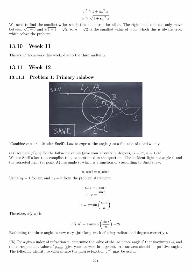
n2 ≥ 1 + sin2 α
n ≥√
1 + sin2 α
We need to find the smallest n for which this holds true for all α. The right-hand side can only movebetween
√1 + 0 and
√1 + 1 =
√2, so n =
√2 is the smallest value of n for which this is always true,
which solves the problem!
13.10 Week 11There’s no homework this week, due to the third midterm.
13.11 Week 12
13.11.1 Problem 1: Primary rainbow
“Combine ϕ = 4r − 2i with Snell’s Law to express the angle ϕ as a function of i and n only.
(a) Evaluate ϕ(i, n) for the following values (give your answers in degrees): i = 5, n = 1.55”We use Snell’s law to accomplish this, as mentioned in the question. The incident light has angle i, andthe refracted light (at point A) has angle r, which is a function of i according to Snell’s law.
n1 sin i = n2 sin r
Using n1 = 1 for air, and n2 = n from the problem statement:
sin i = n sin r
sin r =sin i
n
r = arcsin
(sin i
n
)Therefore, ϕ(i, n) is
ϕ(i, n) = 4 arcsin
(sin i
n
)− 2i
Evaluating the three angles is now easy (just keep track of using radians and degrees correctly!).
“(b) For a given index of refraction n, determine the value of the incidence angle i′ that maximizes ϕ, andthe correspondent value of ϕmax (give your answers in degrees). All answers should be positive angles.The following identity to differentiate the inverse function f−1 may be useful:”
221
d f−1(x)
dx=
1d f(z)dz
∣∣z=f−1(x)
Okay, so they want us to differentiate ϕ(i, n) with respect to i and find its maxima. The formula is clearlyintended for finding the derivative of the arcsine function. Using f−1(x) = arcsin(x), f(x) = sin(x) (since
the arcsine is the inverse of the sine) andd
dzsin(z) = cos(z):
d
dxarcsin(x) =
1
cos(arcsin(x))
That doesn’t answer the entire thing, however. We still need to apply the chain rule, not to mention wecan’t forget about the constant multiplier and the −2i. All in all, we have
∂ϕ(i, n)
∂i= 4
∂
∂iarcsin
(sin i
n
)− 2
The (partial) derivative of the arcsine is then just the chain rule: “the derivative of the outside with respectto the inside, times the derivative of the inside with respect to i” (in this case) is how I remember it best.We know the first part already, and the second part is just the the derivative of sin i times the constantone over n inside. Keeping all this in mind:
∂ϕ(i, n)
∂i= 4
1
cos(arcsin
(sin in
)) cos i
n− 2 =
4 cos i
n cos(arcsin
(sin in
)) − 2
Frankly, this is a bit painful, and as it is allowed, I will use Mathematica to substitute in n and set thewhole thing equal to zero. Doing so (the second part, leaving n as is), I find
2 arctan
√√√√n2 + 2
4− n2− 2√
3
√n2 − 1
(n2 − 4)2
... there has got to be a better way to solve this... But the above does give correct answers.
For n = 1.55, we find i′ = 46.8634, while for n = 1.3 we find i′ = 61.3418.We then plug those values into ϕ(i, n) and find
ϕ(46.8634, 1.55) = 18.6158
ϕ(61.3418, 1.3) = 47.1321
“(c) What is the angle of incidence i of light on a spherical raindrop that will lead to the red in the pri-mary rainbow (give your answers in degrees)? The index of refraction of red light in water is nred = 1.331.”
The red in the rainbow is where ϕmax is for red light, so we just plug n = 1.331 into the above formula, toand then plug that into ϕ(i, n) as above.
i′ = 59.5267
ϕ(59.5267, 1.331) = 42.3698
222
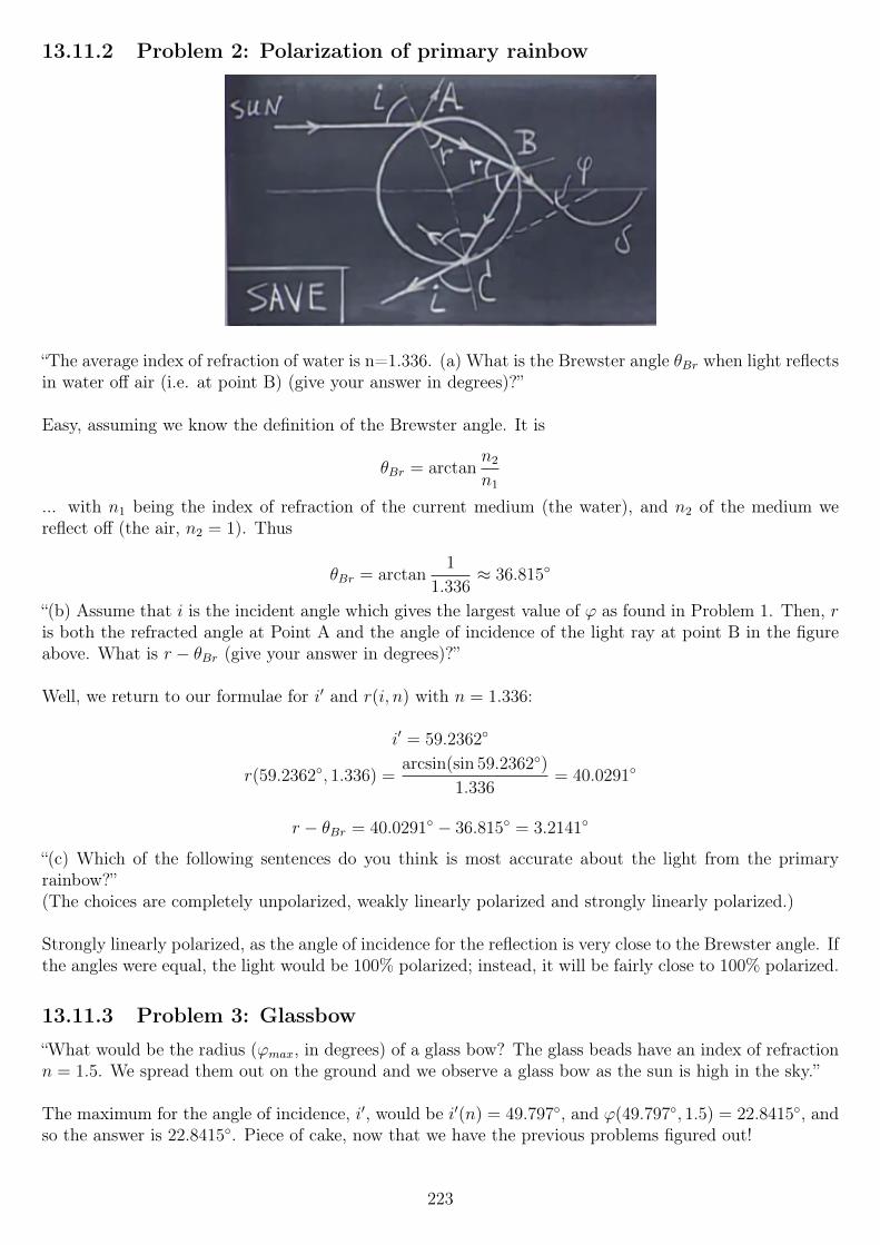
13.11.2 Problem 2: Polarization of primary rainbow
“The average index of refraction of water is n=1.336. (a) What is the Brewster angle θBr when light reflectsin water off air (i.e. at point B) (give your answer in degrees)?”
Easy, assuming we know the definition of the Brewster angle. It is
θBr = arctann2
n1
... with n1 being the index of refraction of the current medium (the water), and n2 of the medium wereflect off (the air, n2 = 1). Thus
θBr = arctan1
1.336≈ 36.815
“(b) Assume that i is the incident angle which gives the largest value of ϕ as found in Problem 1. Then, ris both the refracted angle at Point A and the angle of incidence of the light ray at point B in the figureabove. What is r − θBr (give your answer in degrees)?”
Well, we return to our formulae for i′ and r(i, n) with n = 1.336:
i′ = 59.2362
r(59.2362, 1.336) =arcsin(sin 59.2362)
1.336= 40.0291
r − θBr = 40.0291 − 36.815 = 3.2141
“(c) Which of the following sentences do you think is most accurate about the light from the primaryrainbow?”(The choices are completely unpolarized, weakly linearly polarized and strongly linearly polarized.)
Strongly linearly polarized, as the angle of incidence for the reflection is very close to the Brewster angle. Ifthe angles were equal, the light would be 100% polarized; instead, it will be fairly close to 100% polarized.
13.11.3 Problem 3: Glassbow
“What would be the radius (ϕmax, in degrees) of a glass bow? The glass beads have an index of refractionn = 1.5. We spread them out on the ground and we observe a glass bow as the sun is high in the sky.”
The maximum for the angle of incidence, i′, would be i′(n) = 49.797, and ϕ(49.797, 1.5) = 22.8415, andso the answer is 22.8415. Piece of cake, now that we have the previous problems figured out!
223
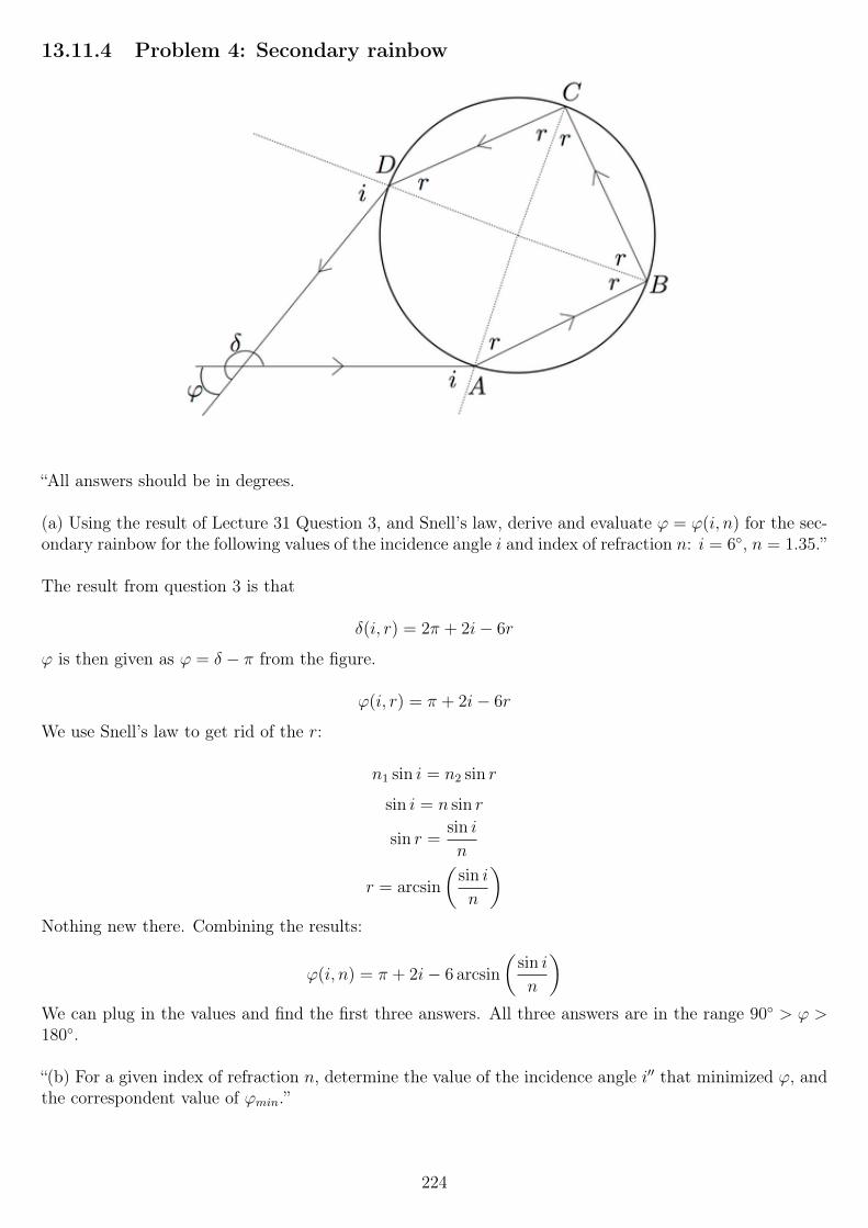
13.11.4 Problem 4: Secondary rainbow
“All answers should be in degrees.
(a) Using the result of Lecture 31 Question 3, and Snell’s law, derive and evaluate ϕ = ϕ(i, n) for the sec-ondary rainbow for the following values of the incidence angle i and index of refraction n: i = 6, n = 1.35.”
The result from question 3 is that
δ(i, r) = 2π + 2i− 6r
ϕ is then given as ϕ = δ − π from the figure.
ϕ(i, r) = π + 2i− 6r
We use Snell’s law to get rid of the r:
n1 sin i = n2 sin r
sin i = n sin r
sin r =sin i
n
r = arcsin
(sin i
n
)Nothing new there. Combining the results:
ϕ(i, n) = π + 2i− 6 arcsin
(sin i
n
)We can plug in the values and find the first three answers. All three answers are in the range 90 > ϕ >180.
“(b) For a given index of refraction n, determine the value of the incidence angle i′′ that minimized ϕ, andthe correspondent value of ϕmin.”
224
This is in a way the same thing as we did for the primary rainbow earlier on. Because the secondary bowis flipped inside-out, the minimum angles are where we will find the colors; all colors are allowed outside(there will be while light outside the secondary).We could differentiate it again, but I will simply use Mathematica’s FindMinimum function here, for thevarious values.For n = 1.35:
i′′ = 71.2981
ϕmin = 55.249
For n = 1.5:i′′ = 66.7163
ϕmin = 86.8651
“(c) What is the angle of incidence i of light on a spherical raindrop that will lead to the red (n = 1.331)in the secondary rainbow?”
This question is again exactly like the two previous, so we do the same thing for n = 1.331:
i′′ = 71.9073
ϕ = 50.3651
13.11.5 Problem 5: Diffraction pattern
“Light of a red laser (wavelength λ = 650 nm) goes through a narrow slit which is only a = 2 micronswide. After the light emerges from the slit, it is visible on a screen that is L = 5 meters away from theslit.
What is the approximate width on the screen (in cm) of the bright central spot? Here width is defined asthe distance between the center and the first minimum.”
If we have the formula we found in lecture, this is very easy.
xn ≈Lnλ
am
n = 1, L = 5m, λ = 650 · 10−9 m, and the answer should be in cm, so
xn ≈5 · 650 · 10−9
2 · 10−6· 100 cm
1 m≈ 162.5 cm
Note: this solution uses the small angle approximation, which was good enough to be marked as correct,but it is actually more than 5% off the correct answer, due to the relatively large angle (I didn’t payattention to that, since my first try was marked as correct). For a more correct answer, we use the formulawe found this week, that is
x = L tan θ = L tan
(arcsin
(λ
d
))
225
13.11.6 Problem 6: Optical resolution of the human eye
“A car with its 2 headlights on is approaching you at night. Approximately how close (in meters) does thecar have to be to you so that you can distinguish the two headlights? Assume that the diameter of yourpupils is 6.5 mm, the distance between the two lights is 1.5 m, and the wavelength of the light is 550 nm.”
Again, this should be fairly easy. There will be diffraction associated with each source on its own, andthey need to be further apart, in angular distance, than the Rayleigh criterion limit of
sin θ = 1.220λ
d
where d = 6.5 mm, the diameter of the lens.
sin θ = 0.10323 · 10−3 ≈ θ
(For such small angles, the sine of the angle and the angle in radians are essentially equivalent.)OK, so we have that but we need the actual distance in meters.
We draw the situation on paper: an isosceles triangle (from our position (right in front of the car) to thetwo headlights.Because it is symmetric, we can split it in two, and have θ/2 radians between one headlight and the car’scenter. One side (the long, non-hypotenuse side, adjacent to θ) of that triangle is then the distance dbetween us and the car, and we find
tanθ
2=
1.5/2
d
d tanθ
2= 1.5/2
d =1.5/2
tan(θ/2)= 0.75 cot(θ/2) ≈ 14531 m
Wow, that’s insanely far! This only counts the diffraction limiting, though... I’d be surprised if this wasactually true in a real situation, given non-ideal eyesight and all that. Hmm.
226
Chapter 14
Exam problems
14.1 Midterm 1
14.1.1 Problem 1: Electric field on the surface of a conductor
The electric field at point A on the surface of a conductor is 49 × 103 V/m. What is the surface chargedensity (C/m2) at that point?
Let’s call the surface charge density σ. The total charge for that tiny area at the surface is Q = σA.We choose a Gaussian pillbox that is located such that the “end cap” is located just above the surface.Via Gauss’s law
EA =σA
ε0
A on the left side is the area of the pillbox, and A on the right side the area of the surface. Of course, wechoose them to be equal, so they cancel:
E =σ
ε0
Thus
σ = Eε0
We know E at that point, so
σ = 49× 103 × 8.854187× 10−12 ≈ 4.3385× 10⁻⁷ C/m2
We can sanity check the units of this. The electric field is in V/m, ε0 is in F/m = (C/V)/m and σ inC/m2 :
Cm2
? =V
m· Fm
Cm2
? =V
m· CV ·m
Cm2
=Cm2
227
14.1.2 Problem 2: Non-conducting charged planes
Two parallel non-conducting sheets of area A = 4m2 are separated by a distance d = 0.007 m. They carryequal but opposite surface charge densities of σ = 7× 10⁻⁶ C/m2.
(a) What is the electric field (V/m) between the plates? (ignore end effects)
We could use a Gaussian pillbox to solve this for an infinite plane (since we are to ignore end effects), butthe result is so easy to remember that I won’t feel guilty for using it. The electric field between two suchplates is
E =σ
ε0
... half of which (σ
2ε0) is from the top plate, and half from the bottom.
So the answer for (a) is
E =7 · 10−6
8.854187 · 10−12≈ 790586.41974 V/m
(b) What is the total energy (Joules) contained in the electric field between the sheets?
We can use U =1
2
Q2
Chere.
Q is given by σA = 4σ = 28 · 10−6 C.
C is given by the geometry, C =Aε0d
=4ε0
0.007≈ 5.059535 · 10−9 F. Thus,
U =1
2
(28 · 10−6)2
5.059535 · 10−9≈ 0.077477 J
(c) A conducting sheet with the same area as the two nonconducting sheets and with thickness h = 1 mm(0.001 m) is inserted between the two sheets. What is the potential difference (Volts) between the sheetswith this conducting sheet in place?
Uh oh. Well, the potential difference without the sheet in place, since the electric field is uniform, is simplyV = Ed ≈ 5534.105 V.If we insert a dielectric, an induced electric field will appear, that cancels out part of the original field; thenet field is reduced by a factor of κ, the dielectric constant for the material. However, that’s for dielectrics- and only when they completely fill the void between the two plates, too.
It turns out the answer is that since the sheet is a conductor, and the electric field inside it is zero, we cansimply integrate over the rest of the distance. That is, we add up the potential difference from the topplate to the conductor, add the potential difference across the conductor (zero), and then the potentialdifference from the bottom of the conductor to the bottom plate.
Since the field is uniform, V = Ed. The distance d to use is then the distance between the plate minusthe thickness of the sheet (where the field is zero):
V = E(d− h)
V =σ
ε0(d− h) =
7 · 10−6
8.854187 · 10−12(0.006− 0.001) ≈ 4743.5 V
228
14.1.3 Problem 3: Incandescent bulbs
An incandescent light bulb A consumes PA = 21 W when it is connected to a V = 126 V battery. Anotherincandescent light bulb B consumes PB = 253 W when it is connected to a V = 126 V battery. We placethe two light bulbs in series. You may ignore the internal resistor in the power supply and you may alsoassume (for simplicity) that the resistance of the light bulbs are independent of the temperature.We connect these two light bulbs in series to the V=126 V battery.(a, b) How much power (in W) is used by bulb A (and B)?
Ah, finally something that’s not intimidating at all to me. Exams always freak me out a bit...
Well, power is given by P = V I = I2R =V 2
R. We know P and V, so we’ll use the last equation and solve
it for R.
P =V 2
R
R =V 2
P
We can now calculate the bulb resistances:
RA =1262
21= 756 Ω
RB =1262
253≈ 62.750988 Ω
We put them in series with the battery of 126 volts, and get a current:
I =V
RA +RB
≈ 0.15389296 A
We can then use I2R to find the power dissipated in each bulb.
PA = (0.15389296)2 · 756 ≈ 17.90438 W
PB = (0.15389296)2 · 1262
253≈ 1.486135 W
All of a sudden the previously weak bulb is the brightest! Let’s sanity check the answers, since this is anexam.The total power must equal the power put out by the battery, V I ≈ 126 · 0.15389296 = 19.93 watts.Indeed it does.
(c, d) What will be the potential difference across bulb A (and B)?
Well, V = IR and we know I and R. Easy.
VA = 0.15389296 · 756 = 116.343 V
VB = 0.15389296 · 1262
253≈ 9.6569 V
Again, we can sanity check: the sum must equal the battery’s voltage, and it does.
229

14.1.4 Problem 4: Circuit
(a) Find all the currents in the circuit above, where R1 = 16 Ohm, R2 = 1 Ohm,R3 = 3 Ohm, V1 = 10 V,V2 = 1 V.
D’oh. I had to insert a picture for this one. Excuse the size/image quality, if it looks bad. It looks goodhere, though.
We can use loop analysis to solve for the currents in this problem. After that, we can calculate voltagedrops across the resistors.Let’s begin by working symbolically.
First, we set up an equation for the left loop, starting at point A, going clockwise around (as an arbitrarychoice). We add when we move over an increase in potential, and subtract when we move over a decrease:
I1R1 − V 1− I2R2 + V 2 = 0
For the right loop, starting at the middle node (where V2, R2 and R3 meet), going clockwise:
R2I2 + I3R3 = 0
We now have two equations, but three unknowns (I1, I2 and I3). We can relate the three with a KCLequation, at the middle node mentioned above:
I1 + I2 = I3
I1 enters from the left, and I2 from above, while I3 leaves to the right. Alternatively, we can sum currentsentering a node and enter the leaving current as a minus, but we would get the same equation, only witheverything on one side and set equal to zero.This gives us the nasty answers:
I1 =(R2 +R3)(V1 − V2)
R1R2 +R1R3 +R2R3
I2 = − R3(V1 − V2)
R1R2 +R1R3 +R2R3
I3 =R2(V1 − V2)
R1R2 +R1R3 +R2R3
I1 =36
67A
I2 = −27
67A
230
I3 =9
67A
We can now calculate the voltage drops over each resistor:
VR1 = I1R1 =36
67· 16 =
576
67V
VR2 = I2R2 = −27
67· 1 = −27
67V
VR3 = I3R3 =9
67· 3 =
27
67V
Adding up the voltage drops along the left loop gives us
−1 +−27
67+ 10− 576
67
which equals zero.For the right loop, the sum is also zero, as VR2 = −VR3.Our answers make sense!
(b) The potential at point G is V(G)=0. What is the potential at point A (in Volts)?
We’ll have to add up the voltage drops we encounter when moving from G to A.
VR3 + V2 =27
67+ 1 =
94
67V
If we add VR1 and subtract V1 from that, we get zero, for the outer loop, so all of our answers satisfy KVL,an excellent sign that they are correct. At the very least, it’s not as sign that they’re wrong !
14.1.5 Problem 5: Point charge in a hollow conducting sphere
A very thin hollow conducting sphere has a radius of R = 0.14 m. The center of the sphere is at S. Acharge of q = 8×10⁻⁶ C is present at point P which is located d = 0.06 m from S. Assume that this chargestays at this position (thus it cannot move). We draw a line from S to P and extend it beyond the radiusof the sphere.
What is the Electric field strength (V/m) at point D which is located on the line from SP at a distance of` = 0.76 m from S (thus 0.7 m from P)?
Aha! While this looks like it could be very scary due to the non-centered charge, the fact that the shell isconducting and a sphere makes it almost trivial!The positive charge inside will cause the inside surface of the sphere to hold a charge of −q to cancelthe E-field inside the conductor out. This charge will be non-uniformly distributed, because the charge isoff-center.However, the sphere was neutral to begin with, so there will be a charge of +q on the outside.This charge will, amazingly, be uniform. We know from earlier on - or could re-calculate it using Gauss’slaw - that a charged sphere produces an electric field exactly as a point charge at the center would. Thus,we can use the good old point charge formula:
E =Q
4πε0r2
where Q = +q is the same as the charge inside the sphere, and r is the distance between the center (notthe surface!) and the point D.
231
E =8 · 10−6
4πε0(0.76)2≈ 124481.34 V/m
That’s our final answer. Since the conductor acts as a Faraday cage, the position of the charge inside iscompletely irrelevant! As long as the charge is inside the cavity, the external electric field will be the same- after it has settled down (which happens extremely quickly after a change in position).
14.1.6 Problem 6: Charges on an equilateral triangle
A charge of q1 = −2× 10⁻⁶ C is located at corner A of an equilateral triangle. A charge q2 = 4× 10⁻⁶ Cis located at corner B and a charge of q3 = 8× 10⁻⁶ C is located at corner C. The distance AB = 0.26 m(the other two sides of the triangle are the same).The point P is located exactly in the middle of q1/point A and q3/point B, along the x axis, and exactlybelow q2/point B.
(a) What is the x-component of the Electric field (in V/m) at point P which is located half way betweenA and C?
Before we start crunching numbers, let’s think about this (which is always a good strategy)! The electricfield from each point charge alone is always radially outwards (or inwards, for negative charges). Thus, thex-component of the electric field from a charge directly above you (xcharge = xpoint) will be zero! Therefore,we can treat this as a one-dimentional problem, and completely ignore q2.
Therefore, the x component is given by
Ex =q1
4πε0(AP )2+
q3
4πε0(PC)2
AP = PC =AC2
=0.26
2= 0.13 m.
So, accounting for directions (q1 is negative, and its field is towards the left at point P; q2 is positive, itsforce is also towards the left at point P):
Ex =−2 · 10−6
4πε0(0.13)2+−
(8 · 10−6
4πε0(0.13)2
)≈ −5.318085 · 106 V/m
(b) What is the y-component of the Electric field (in V/m) at point P?
Similarly as before, due to the location of the point and the charges, we can now completely ignore chargesq1 and q2, so this should be a piece of cake. All we need to do is to find the distance BP, and plug it intoCoulomb’s law.BP is equal to the height of the equilateral triangle. As I don’t remember the formula for that, I drew itup on paper. Via Pythagoras’ theorem, we get
h2 +
(d
2
)2
= d2
h2 =4d2
4− d2
4
h =
√3
2d
Thus
BP =
√3
2· 0.26 m
232
Ey = − 4 · 10−6
4πε0(0.5√
3 · 0.26)2≈ −709077.12957
Note that since the field is radially outwards from the charge, and P is located below the charge, the fieldwill be downwards, and so the y-component must be negative. The distance from the charge is greaterthan that of the charges in the previous problem, so we expect the magnitude of the field to be quite a bitlower, which it is.
(c) What is the Electric Potential (in Volts) at point P?
Work, work! Well, at least potential is not a vector, so we don’t have directions and such to think about.The potential at a point is the sum (superposition) of the potential due to each charge alone, as with
electric field strength. We just add the potential due to each charge alone (V =Q
4πε0r) :
VP =1
4πε0
(q1
AP+
q2
BP+
q3
CP
)
VP =10−6
4πε0
(−2
0.13+
4
0.5√
3 · 0.26+
8
0.13
)≈ 574470.61 V
(d) What is the Electric Potential Energy (configuration energy) in Joules of this system of 3 charges?
Last one. Well, for this problem anyway. Say the potential at infinity is zero. We start out with nothing,and so the potential energy is zero. We add charge q1, and the potential energy is still zero - but thepotential is not. We add a second charge, and the potential energy is now V1q2. We add the third charge,and get a potential energy of V1q2 from before, plus V1q3 + V2q3 from adding the new charge. That is:
U =q1q2
4πε0r12
+q1q3
4πε0r13
+q2q3
4πε0r23
Looking at the diagram, r12 = r13 = r23 = 0.26 m, so we can factor out that, too:
U =1
4πε0 · 0.26(q1q2 + q1q3 + q2q3)
U =10−6 · 10−6
4πε0 · 0.26((−2)(4) + (−2)(8) + (4)(8)) ≈ 0.27661247 J
14.1.7 Problem 7: Capacitor network
Two ideal plate capacitors in air, with capacitance C1 = 4 × 10⁻⁶ Farad and C2 = 4 × 10⁻⁶ Farad, areconnected to a battery of voltage V = 10 Volts as shown schematically below. The plates are separatedby a distance d = 0.003 m.(The diagram is too simple to reproduce: it has two capacitors, C1 to the left and C2 in the middle,connected in parallel with a voltage source. The upper plates are connected to the positive side of thevoltage source.
(a) What is the total charge residing on the upper plate of capacitor C1 (in Coulombs)? Make sure youhave the correct sign.
Q = CV , so this one is simply
Q = 4 · 10−6 · 10 = 4 · 10−5 C
233
(b) What is the total charge residing on the lower plate of capacitor C2 (in Coulombs)? Make sure youhave the correct sign.
Note the lower plate, and of C2. The magnitude is the same as above (C1 = C2, as given), but the lowerplate will have the negative charge, so we negate the above answer.
(c) What is the electric field (direction and magnitude) between the plates of capacitor C1 (direction andmagnitude)?
V = Ed for a parallel plate capacitor, so E =V
d. V and d are given, so
E =10
0.003= 3333.33 V/m
The direction is downwards (from positive to negative).
We now disconnect the battery but leave the two capacitors connected together as shown. After discon-necting the battery, we fill the the entire air gap of the capacitor C2 with a dielectric (κ = 4).
(d) Now, what is the total charge residing on the upper plate of capacitor C1 (in Coulombs)? Make sureyou have the correct sign.
OK, so let’s think a bit. The battery is disconnected, so the potential difference between the plates is nolonger fixed. It must however be the same for both capacitors.The charge is trapped on the capacitors, but we have two, and they are still connected, so while Q1 +Q2
must clearly equal the initial total charge on them, it should be able to move around between the two.
After a very long struggle I solved this one. I first wrote down a few things that simply can not change,period. V1 = V2 due to the connection, so I simply call that V :
C1 =Q1
V
C2 =Q2
V
Q1 +Q2 = Qinitial = V (C1 + C2)
C2new = C2K
C1new = C1
C1 simply can not change; it is given byAε0d
, and none of those change, so it must be constant.With the same argument, C2 must increase by a factor κ, as the above is true for C2 as well, except wiinsert a dielectric which always increasese capacitance by κ.The voltage can and will change, but the total charge cannot. With all this in mind, we set up and solvethis system:
Q1 +Q2 = Qinit
C1 =Q1
V
4 · C1 =Q2
V
... with C2 = 4C1 to avoid adding a fourth line. We also have the constraint that V > 0.This gives us a solution of
234
Q1 =Qinit
5
Q2 = 4Q1
V =Q1
C1
After we plug in Qinit = V (C1 + C2) = 8 · 10−5 C, we get
Q1 =8
5· 10−5 =
1
62500C
Q2 =32
5· 10−5 =
1
15625C
V =8
5· 10−5 · 1
4 · 10−6= 4 V
They now ask us for Q1, Q2, and the electric field between each set of plates. The electric field is E =V
dfor both capacitors, so we plug in V = 4 and get our answer.
14.2 Midterm 2
14.2.1 Problem 1: RL circuit
“The switch in the circuit below has been open for a long, long time, R1 = 4.0 Ohm, R2 = 5.0 Ohm,L = 0.045 H, V = 5 V. The internal resistance of the battery is negligibly small.“Determine the currents I1, I2, I3 (in Ampere) in the resistors and in the self-inductor at the moment(a) just after the switch is closed:”
OK, so looking at the circuit (which is not reproduced here), if the switch has been open for a long time,then the current everywhere is zero.Just after closing the switch, the inductor current will still be zero, and so I3 = 0.Because that part of the circuit is essentially an open circuit, we have a series circuit with the battery, R1
and R2:
I1 = I2 =V
R1 +R2
=5
9A
I3 = 0
“(b) a long time after the switch is closed.”A long time after, the current in the inductor will be at a maximum, limited only by the battery and R1.R2 will be completely bypassed by the inductor, which now looks like a short circuit, and so I2 = 0, andI1 = I3.
I1 = I3 =V
R1
=5
4A
I2 = 0
235
14.2.2 Problem 2: Non-conservative fields
“Two voltmeters, Vright and Vleft, each with an internal resistance of 106 Ω are connected through wires ofnegligible resistance (see the circuit below). The “+” side of both voltmeters is up as shown. A changingmagnetic field is present in the shaded area.
At a particular moment in time Vright reads −0.7 Volt (notice the - sign).
(a) What, at that moment, is the magnitude of the induced EMF (in Volts) in the circuit?”OK. The circuit diagram is very simple: two voltmeters, side by side, connected to each other. So bothhave the plus side upwards, and then the + sides are connected at the top, and the - sides connected atthe bottom. There’s a changing magnetic flux in the middle of the loop.
Let’s not fool ourselves here; we will use Faraday’s law, and map out the circuit based on the electric fieldsin it, not based on Kirchhoff’s rules, which don’t apply here!
If we start at the bottom node, going clockwise, we first encounter Vright, which measures −0.7 volts,meaning the current though it goes into the bottom and out of the top, or else it would display a positivevalue. Thus, the current is going counterclockwise in the loop.
We now know the voltage across the voltmeter (which is not really a “voltage drop”, though, but an inducedEMF), and the resistance, so
I =V
R
I =−0.7
106= −7 · 10−7 A
Since the total resistance of the loop is 2 · 106 ohms, and Ohm’s law holds, the total EMF is
V = IR = −7 · 10−7 · 2 · 106 = −1.4 V
Question (a) wants the magnitude of this, so 1.4 volts.
“(b) At that moment in time, what is the reading of Vleft? (make sure you have the correct sign!)”
That voltmeter must have a a current of the same magnitude through it, but it is positive (as it goes intothe positive terminal), and so
Vleft = IR = 7 · 10−7 · 106 = 0.7 V
14.2.3 Problem 3: Bainbridge mass spectrometer
“A Bainbridge mass spectrometer is shown in the figure. A charged particle with mass m, charge|q| = 4.8 × 10⁻¹⁹ C and speed v = 3 · 106 m/s enters from the bottom of the figure and traces outthe trajectory shown in the fields shown. The only electric field E = 10 · 103 V/m is in the region wherethe trajectory of the charge is a straight line.
(a) When the particle is moving through the first (straight-line) segment of its trajectory, what is themagnitude of the magnetic field B in Tesla?”“The particle moves towards the left in a magnetic field pointing into the page, so it must be positivelycharged. The E-field is towards the right, and so for the particle to move in a straight line, the magnitudeof the electric force and the magnetic force must be equal.
236
The E-field is uniform between the plates, at 10 · 103 V/m (given above); alternative usits would be N/C,which will be more useful here. The electric force on the particle is thus
FE = qE = q · 10 · 103 = 4.8 · 10−19 · 10 · 103 = 4.8 · 10−15 N
... and the direction is, then, to the right. The strength of the magnetic force on the particle must equalthis, only that the magnetic force will be towards the left. The magnetic force is given by
FB = q(v ×B) = qvB
... since the B-field is perpendicular to v, sin θ = 1, and we get a nice, simple equation. Solving for theB-field strength, we find
FB = qvB
B =FBqv
Since FB must be equal to the electric force (in magnitude), we find
B =FEqv
=4.8 · 10−15
4.8 · 10−19 · 3 · 106= 0.0033 T
as the answer to (a).
“(b) The charge hits the left wall of the spectrometer at a vertical distance h = 0.157 m above where itentered the upper region and a horizontal distance L = 0.374 m to the left of where it entered the upperregion (see sketch). What is the radius r of the trajectory in m?”
Well, first, let’s have a guess at the rough size of the answer. Via the sketch, r is slightly larger than L/2(L is a bit smaller than the diameter of the circle the particle would trace). So if we find r ≈ 0.2 thenthat would look about right.
We know that
R =mv
qB
... but we don’t know R and we don’t know B (the B-field above is for another region of the device!), sowe can’t use that as-is.
Looking at the diagram, we can simply use the Pythagorean theorem to find r:
h2 + (L− r)2 = r2
h2 + L2 − 2Lr = 0
h2 + L2 = 2Lr
r =h2 + L2
2L
We stick our values in and find r ≈ 0.219953 m.
“(c) The mass of the particle can be determined using the radius r, the charge q, the speed v, and themagnetic field B0. Using a value of B0 = 0.2 T, evaluate the mass of the particle in kg. (Note that themagnitude of the field in the curved section, B0, is NOT the same as the magnitude in the straight section,B, found in part a).”
237
Now we can use the radius equation! We just need to solve it for m.
R =mv
qB0
m =qRB0
v
With our values, m ≈ 7.0385 · 10−27 kg.
14.2.4 Problem 4: RL circuit
“In the circuit shown in the figure below, the switch closes at t = 0, R = 2.0 Ohm, E = 7 V, L = 0.085 H.(a) What are the currents (in A) through the two bottom branches at t = 0+ (just after the switch isclosed)?”
As in the previous (very similar) circuit, I1 = 0 at this point, because the inductor won’t allow any currentto pass through without at least some time passing.
I2 is then depends only upon the EMF and the resistances 2R +R = 3R, so
I2 =E
3R=
7
6A
“(b) What are the currents (in A) through the two bottom branches at a much later time t ≈ ∞?”
In this case, the current through the inductor has reached its maximum, and it is a short circuit. ThereforeI2 = 0, and
I1 =E
2R=
7
4A
14.2.5 Problem 5: Magnetic field of a loop
“A current I = 4.9 A flows around a continuous path that consists of portions of two concentric circles ofradii a and a/2, respectively, where a = 1 cm, and two straight radial segments. The point P is at thecommon center of the two circle segments.
Calculate the components of the magnetic field (in T) at point P.”
Okay. So neither of the straight wire segments contributes to the B-field at point P, so we can neglectthem completely, and focus on calculating the B-field due to the two arcs.The field ought to be in the +z direction alone, so I would expect the x- and y-components to be zero.More on that later.
Well, let’s see then. We use Biot-Savart, which says that
~dB =µ0
4π
I
r2(~d`× r)
... where ~d` is a segment along the current-carrying wire, always aligned with the current’s direction.
Since we need to calculate the B-field due to two arcs, and then vectorially add the two, we will do this ina general way, and solve it for an arc of radius r, and then substitute in r = a and r = a/2 later on.Since an arc is part of a circle, we have the wonderful properly that |~d` × r| = d`, since they are alwaysexactly perpendicular, and the magnitude of r is 1 by definition. The direction is given by the crossproduct, and will be z (out of the page) for all d`.
238
~d`× r = |~d`||r|sinθ = d` · 1 · 1 = d`z
So we now have
~dB =µ0
4π
I
r2d`z
r is the distance between all points on the wire, and point P, so we don’t need to make any substitutionsthere. (We will later, when we are done with the integration.)Via arc length formulas we find that d` = rdθ, so
~dB =µ0
4π
I
r2rdθz
Thus, we can integrate:
~B =
∫arc
~dB =
∫ π
0
µ0
4π
I
r2rdθz =
µ0
4π
I
r
∫ π
0
dθz
~B =µ0
4π
I
rπz =
µ0I
4rz
This resembles the B-field in the center of a full circle - in fact, it’s exactly half of that! So that makessense.Let’s now make the substitutions, then. We have one arc with radius r = a/2 where the current goesupwards (in the plane of the page, so +y at the center), which makes the B-field go out of the page.Another arc of radius r = a has the current going down at the center, which contributes to a B-field goinginto the page.
Since the current is the same, and the one with radius a/2 is closer to the point, the net B-field will pointout of the page (the closest one will “win”). So we have then, that
~B =µ0I
2az +
µ0I
4a(−z) =
µ0I
2az − µ0I
4az
~B =µ0I
4az
So the components, and our answers, are
Bx = 0 T
By = 0 T
Bz =4π10−7 · 4.9
4 · 0.01≈ 0.000153938 T
14.2.6 Problem 6: Magnetic field of a current-carrying ribbon
“Consider a thin, infinitely long conducting ribbon that carries a uniform current density j (current perunit area). The width of the ribbon is w and its thickness s is extremely small (s w). P is a point inthe plane of the ribbon, at a large distance (x s) from the ribbon edge. (See the figure below)
What is the magnitude of the magnetic field B (in T) at point P for the following values of w , j, s andx? w = 6 cm; s = 0.1 cm; j = 1 A/m2 and x = 16 cm.”
Oh my. Well... Let’s see. If we divide the cross-sectional area s × w into pieces of s dr (dr to avoidambiguity with dw and w - r is the distance between the piece and the point P) and integrate the B-fielddue to each current j s dr , will that be enough? Or do we need to do a double integral where we consider
239
ds and dr?Since s x, and s is described as “extremely small”, I will in fact assume that we ignore the thickness,and treat it as essentially 0. That means that we won’t bother calculating the B-field due to the top layer,the bottom layer, and an infinite amount of layers in between, but indeed treat it as a 1-dimensional setof currents, each at a different distance from the point P , with the closest being r = x and the furthestbeing r = x+ w.
Since the question only asks for the magnitude, as a single number, we won’t have to worry about direc-tions and such.
We can find each current i (I won’t call it di since we won’t integrate it to find the full current) as
i = j dA = j s dr
At this point, I started working with Biot-Savart... and realized that it won’t work. I got stuck whenI thought I could treat the system as an infinitely short (depth-wise) wire, and realized that I need tointegrate d` in the direction in which is is 0... D’oh!
Well, Ampere’s law can work instead, actually. To use it, we treat the system as a set of infinite wires,stacked width-wise. So each wire has area s dr, but since s is very small, we can neglect it (via the problemdescription), and we get a set of infinite wires of ≈ zero radius, where Ampere’s law applies just fine forthe really rectangular shape.
Let’s then look at the B-field due to one such “wire”. Clearly, it will be equal at all equidistant pointsfrom the “wire”, so that we can use Ampere’s law and get
∮~dB · ~d` = dB2πr. Since there is no changing
electric flux (and point P is in empty space), we use the simple version of Ampere’s law:
dB2πr = µ0Ipen
What is Ipen here? Well, we choose the Amperean circle with the radius that equals the distance to thepoint P , and attach a flat surface to that, so it is the full current j s dr though the tiny wire segment.That means that we have
dB2πr = µ0j s dr
dB =µ0j s dr
2πr
Well, the dimensions work out to be tesla, so this looks promising.We can now integrate the above, with r (the distance between the “wire” and P) x to x+ w.
B =
∫ x+w
x
µ0j s dr
2πr=µ0j s
2π
∫ x+w
x
dr
r
B =µ0j s
2πln
(x+ w
x
)This does indeed give a green checkmark for the answer. With the given values we find B ≈ 6.36907 ·10−11
tesla.
14.2.7 Problem 7: Magnetic field of a rotating charged sphere
“A spherical shell of radius R carries a uniform surface charge density (charge per unit area) σ. The centerof the sphere is at the origin and the shell rotates with angular velocity ω (in rad/sec) around the z-axis(z = 0 at the origin). Seen from below, the sphere rotates clockwise. (See the figure below)
240
(a) Calculate the magnitude of the total current (in A) carried by the rotating sphere for the followingvalues of σ, ω and R:σ = 5× 10⁻⁴ C/m2, ω = 8 rad/s and R = 1 m.”
I managed to get a correct answer on this on the test, despite using incorrect methods to solve it. Nowthat I’ve realized two things I did wrong, I’ll try again and see whether I can find the correct answers (notjust something close, but the actual answer!) or not.
First, we will model this as a set of circular (with an infinitesimal height) current loops. That is, we cutthe sphere up in the x-y plane, such that only extremely thin slices remain. If the radius of the sphere isR, and we call the radius of each circle r, we will find via trigonometry that
r = R sin θ
where θ is the polar angle (the angle from the z axis). Clearly, each circle will have a different radius,depending on where it is on the sphere. Only the one centered at the origin (the great circle) will haver = R, while ones closer to the poles will approach 0 radius.
That’s one dimension; to find an area element, we need to multiply that by a dθ or something or another.Well, we know that arc length is given by Rdθ, so that the circumferance of the sphere (or of the sphere’sgreat circle, rather) is 2πR; for half the sphere, it’s simply πR, etc. So the angle in radians times theradius.It really isn’t any harder than that, so we have
dA = 2πr(Rdθ)
= 2πR2 sin θdθ
As a sanity check, let’s integrate that over the entire sphere, and see if we find A = 4πR2. If we don’t, itis clearly incorrect.
A =
∫ π
0
2πR2 sin θdθ
= 2πR2
∫ π
0
sin θdθ
= 4πR2
Excellent! Let us continue with the physics.
First off, part (a): the total current. This can be found easily: current is charge moving past a pointper unit time, and the period of each “ring” of current will be the same, as they are rotating together.
Therefore, the total current is the total charge, σ4πR2, divided by the period T =2π
ω, or
Q = σ4πR2
T =2π
ω
I =Q
T=σ4πR2ω
2π= 2σωR2 = 0.008 A
We can also do this the “proper” way to prove that the above is correct. In this case, we use the areaelement dA we found, and integrate it over the surface area, while multiplying by σ, and dividing by theperiod.An infinitesimal current di is given by
241
di =σdA
T=σωdA
2π=σω(2πR2 sin θdθ)
2π= σω(R2 sin θdθ)
Integrating that over the sphere, the total current is
I =
∫ π
0
σωR2 sin θdθ
= σωR2
∫ π
0
sin θdθ
= 2σωR2
... which is exactly the equation we found above, so our answer of 8 mA looks correct!
“(b) Calculate the magnitude of the magnetic field B(z) (in T) that is generated by the circular current ofthe rotating shell at a point P on the z-axis for the following values of σ,ω, z and R:(same values, plus z = 2.3 m)”
Okay. Since we are considering the currents as circular loops with an infinitesimal height, we can useBiot-Savart to find the B-field along the axis of one such loop. We have done that before, so I will simplyrefer to the result. It says that
Bz =µ0
2
IR2
(R2 + z2)3/2
Since we are integrating a whole set of such loops, I will refer to that as dB instead. In the above, R refersto the radius of the circular loop, which is given by little r = R sin θ in our case.z is the distance from the center of the current loop to the point P where we find the B-field (let’s callthat Pz, as in the z-coordinate of point P), so we need to substitute in an expression for that distance forz. We get
dB =µ0
2
di r2
(r2 + (Pz − z)2)3/2
Substituting in the value for di we found, we have
dB =µ0
2
σω(R2 sin θdθ) r2
(r2 + (Pz − z)2)3/2
Ugh, so now we have both z and θ as variables, plus r (which is R sin θ). Still, two is one too much. Weneed to rewrite θ in terms of z or vice versa; I chose to use z = R cos θ (conversion from cylindrical tospherical coordinates) here. That gives us, if we also replace r = R sin θ at the same time,
dB =µ0
2
σω(R2 sin θdθ) (R sin θ)2
((R sin θ)2 + (Pz −R cos θ)2)3/2
What a mess! We can do some of the squares, to simplify:
dB =µ0
2
σωR4 sin3 θdθ
(R2 sin2 θ + (Pz −R cos θ)2)3/2
Hardly pretty, but we can actually integrate this now; we only have constants and one variable, θ. Ofcourse, doing this integration manually would be madness. Doing it symbolically, using software, wouldprobably also be madness. We can do a numerical integration, however, by giving the software the valuesfor all the constants, and telling it to integrate numerically. With Mathematica, this is done by settingthe constants, and then using the NIntegrate function.
242
Using NIntegrate, or something similar, we evaluate the following integral:
B =
∫ π
0
µ0
2
σωR4 sin3 θdθ
(R2 sin2 θ + (Pz −R cos θ)2)3/2
With constants moved outside the integral:
B =µ0σωR
4
2
∫ π
0
sin3 θdθ
(R2 sin2 θ + (Pz −R cos θ)2)3/2
Solving the integral gives us B ≈ 2.75419755 · 10−10 T, which is correct! (Not only accepted as correct i.e.within 5%, but as far as the answer is given, looks to be exactly correct.)
14.3 Midterm 3
14.3.1 Problem 1: RC Circuit
Here we go.
“The circuit below consists of three identical resistors each with resistance R = 21 Ohm, two identicalbatteries with emfs E = 17 V, and a capacitor with capacitance C = 551µF. The capacitor is initiallyuncharged at t = 0.”
The first sub-questions ask for i1, i2, i3 and the capacitor’s voltage after a “very very long time” t RC.Well, the capacitor will act as an open circuit after such a long time. Thus, the entire left loop will at asif it is disconnected, so i1 = 0. We can redraw the circuit with only the right loop, and find an extremelysimple circuit:
i1 = 0
i2 = i3 =E
2R=
17 V2 · 21 Ω
≈ 0.40476 A
For the rest, we can do turn the circuit into its Thevenin equivalent.First, we find the open-circuit voltage for the port where the capacitor is located. That is, we remove thecapacitor, and then analyze the circuit that remains.The left-hand loop becomes disconnected, and the voltage is decided by the right-hand loop alone.We can either use KVL around the loop, or simply see that the circuit is a voltage divider, with R1 =R2 = R, so the voltage across the middle resistor is half of E. In addition to that, we have the leftmostvoltage source, which is upside down (the way I think of it), that is, its voltage is positive downwards.
We go around the left “loop” (never mind that there’s a hole where the capacitor was, we include that),clockwise, starting in the bottom middle (below the center resistor):
−i3R− E + VTH = 0
VTH = E + i3R
VTH = 17 + 8.5 = 25.5 V
VTH = 25.5 V
Next, we need to find the equivalent resistance into that port. We “turn off’ the voltage sources by turningthem into shorts (current sources, if any, are turned into open circuits), and redraw the circuit. It becomesobvious that the equivalent resistance is
Req = R + (R||R) = R + (R2
2R) = 1.5R
243
So we can now analyze a much simpler circuit: a series circuit of a voltage source (25.5 volts), a resistor(1.5 · 21 Ω = 31.5 Ω) and the capacitor.
After a long time, clearly, the capacitor’s voltage will equal the battery’s, or there would still be a currentrunning. Therefore,
VC(t→∞) = 25.5 V
“(d) Assuming that the capacitor starts uncharged, how long will it take (in seconds) for the voltage acrossthe capacitor to reach 3/4 of its maximum value?”We can use the same circuit, and the equation
VC(t) = VTH
(1− exp(− t
RTHC)
)Set it equal to three-quarters VTH and solve for t...
VTH
(1− exp(− t
RTHC)
)=
3
4VTH(
1− exp(− t
RTHC)
)=
3
4
− exp(− t
RTHC) = −1
4
− t
RTHC= ln
1
4
t = −RTHC ln1
4
t = RTHC ln 4 ≈ 0.02406 s
14.3.2 Problem 2: RLC circuit
“A solenoid has N = 470.0 turns, length d = 10 cm , and radius b = 0.4 cm, (b d). The solenoid isconnected via a switch, S1, to an ideal voltage source with electromotive force E = 5 V and a resistor withresistance R = 49 Ohm . Assume all the self-inductance in the circuit is due to the solenoid. At timet = 0, S1 is closed while S2 remains open.(a) When a current I = 1.02 · 10−2 A is flowing through the outer loop of the circuit (i.e. S1 is still closedand S2 is still open), what is the magnitude of the magnetic field inside the solenoid (in Tesla)?”
All right. So we don’t need to do any circuit analysis for this step, but we do need to calculate the B-fieldinside the solenoid (and then the inductance). We could use a known result, but I will derive it usingAmpere’s law.
We choose an Amperean loop, in the form of a rectangle, placed such that one side (length c) is insidethe solenoid; the other side’s dimension is irrelevant, if it is long enough that the second length c side isoutside the solenoid.
The basic version of Ampere’s law (we won’t need the displacement current term, as the change in electricflux will be 0) tells us ∮
~B · ~d` = µ0Ipen
In a solenoid, the B-field is approximately constant inside, and approximately 0 outside. It will be com-pletely parallel to the length c side, but completely perpendicular to the other side. Therefore, only one
244
side of the loop contributes to the left side: the one inside.
We attach a flat surface to this loop, to find the current that penetrates it. The current may/will penetratemultiple times, since N is large. It will penetrate N times, multiplied by the ratio of the loop’s length tothe solenoid’s:
Ipen = INc
d
The left-hand side gave us c for the line integral’s length:
cB = µ0INc
d
B = µ0IN
d
This result looks familiar, except d is usually called `.We can now answer the first sub-question, of the B-field:
B = µ0IN
d= 4π10−7 · 1.02 · 10−2 · 470
0.1≈ 6.024 · 10−5 T
“(b) What is the self-inductance L of the solenoid (in H)?”The definition of self-inductance is the flux, divided by the current:
L =ΦB
I
Which also means that
ΦB = LI
dΦB
dt= L
dI
dt
(keeping in mind to multiply by N to find the total flux, as needed).
In other words, we need to find the flux inside the inductor. To do so, we attach a surface to the inductor’sloop - a very weird surface (a helical surface), but we can find the flux easily:
ΦB = NAB
... where A is the cross-sectional area of the solenoid, and N of course the number of windings.
ΦB = N · πb2 · µ0IN
d
L =ΦB
I= πb2 · µ0
N2
d
L ≈ 0.000139533 H
“(c) What is the current (in A) in the circuit a very long time (t L/R) after S1 is closed?”At that point, I = ER (since the inductor has no resistance in this model).
I =E
R=
5
49≈ 0.102 A
“(d) How much energy (in J) is stored in the magnetic field of the coil a very long time (t L/R) afterS1 is closed?”
U =1
2LI2 ≈ 1
20.000139533 ·
(5
49
)2
≈ 7.26432 · 10−7 J
245
“For the next part, assume that a very long time (t L/R) after the switch S1 was closed, the voltagesource is disconnected from the circuit by opening switch S1. Simultaneously, the solenoid is connected toa capacitor of capacitance C = 851µF by closing switch S2. Assume there is negligible resistance in thisnew circuit.(e) What is the maximum amount of charge (in Coulombs) that will appear on the capacitor?”
Hmm. We will have an LC circuit, since the rest is disconnected.Since there is stored energy to begin with (in the inductor), and no energy is lost to resistance, the circuitshould oscillate forever.I don’t see an easier way to solve this (actually, for this question, we could probably use U =
1
2
Q2
C, but we
need some other solution for the next quetion), so let’s look at setting up the differential equation usingFaraday’s law: ∮
~E · d` = −dΦB
dt
First, we go around the circuit starting at the top (arbitrarily), going clockwise - in the direction of theinitial current.The inductor doesn’t contribute to the line integral, as there can be no electric field inside it, having noresistance.For the capacitor, we find VC = Q/C (C = Q/V , V C = Q, V = Q/C); charge will build up on the bottomplate for this current direction, and so the E-field is is the same direction we are moving, and
Q
C= −LdI
dt
We can use I =dQ
dt:
Q
C= −Ld
2Q
dt2
We use the initial conditions Q(t = 0) = 0 (no charge on the capacitor) and Q′(t = 0) = I0 (initial current)to solve the differential equation, and find (I used Mathematica)
Q(t) = I0
√LC sin
(t√LC
)That can easily answer the question, since the sine will move between -1 and +1. The maximum charge is
Qmax = I0
√LC =
E
R
√LC ≈ 5
49
√0.000139533 · 851 · 10−6 ≈ 3.516 · 10−5 C
“(f) How long does it take (in s) after S1 is opened and S2 is closed before the capacitor first reaches itsmaximum charge?”That would be when sin
t√LC
= 1 , or whent√LC
= π/2.
t√LC
=π
2
t =π√LC
2
t ≈ 0.000541281 s
BTW (they didn’t ask for it), the current is given by the derivative of the charge, of course, so
I(t) = I0 cos
(t√LC
)
246
14.3.3 Problem 3: Energy flow of a capacitor
“Consider a charging capacitor made out of two identical circular conducting plates of radius a = 9 cm.The plates are separated by a distance d = 10 mm (see figure below, note that d a). The bottom platecarries a positive charge
Q(t) = +Q0
(1 +
t
T
)with Q0 = 2 · 10−6 C and T = 0.006 sec, and the top plate carries a negative charge −Q(t). The currentthrough the wire is in the positive k-direction. You may neglect all edge effects.
(a) Calculate the components of the electric field (in V/m) inside the capacitor for t = 2T .”
Three questions (this being one) want the answers as components in r, θ and k, so they clearly want usto use cylindrical coordinates for this one.
As for the electric field, that is given by
E =σ
ε0
... in the direction from the positive to the negative charge, so +k in this case. σ can be found by dividingthe total charge by the plate area:
σ =Q
A=
Q
πa2
So
E =σ
ε0=
Q
ε0πa2
For the change at t = 2T , using the equation, we find
Q(t = 2T ) = Q0
(1 +
2T
T
)= 3Q0
We find then,
Er = 0 V/m
Eθ = 0 V/m
Ek =Q
ε0πa2=
3Q0
ε0π(0.09)2≈ 2.66298 · 107 V/m
... that seems insane, as it is several (not far from 9) times higher than the maximum possible E-field in air,before breakdown occurs... I keep getting the same answer though, after having double- and triple-checkedmy calculations! Let’s see...
C =Aε0d≈ (π0.092)(8.854187 · 10−12)
0.01≈ 2.25 · 10−11 F
V =Q
C=
6 · 10−6
2.25 · 10−11≈ 266666.67 V
Well, the results are in line with everything else. I still find them bizarre, though!I actually posted about this on the wiki, to ask whether “unphysical” values could be valid, and the answerwas yes, they didn’t choose the values to avoid the breakdown limit. So the above is most likely correct
247
after all.
“(b) Calculate the components of the magnetic field B(r, t) (in Teslas) at time t = 2T inside the capacitorat a distance r = 0.9 cm from the central axis of the capacitor.”First, as a sanity check, let’s calculate the B-field outside the wire. Using Ampere’s law (without thedisplacement current term),
B2πr = µ0I
B =µ0I
2πr
B ≈ 2.222e− 5 · I
The current is given by the derivative of Q at t = 2T , which is constant at Q0/T (where T = 0.006, givenearly in the problem), so I ≈ 3.333 · 10−4 A.
B ≈ 7.405 · 10−9 T
... for the B-field outside the wire. I do believe this is equal to the answer (it turned out it wasn’t!), but Iwill calculate it using the displacement current term inside the plates, to do things right.
The equation we need is then ∮~B · ~d` = µ0
(Ipen + ε0
dΦE
dt
)Ipen = 0 since we will be mid-air (or mid-vacuum). We again to around a circle with radius r = 0.9 cm, so
B2πr = µ0ε0dΦE
dt
B =µ0ε02πr
dΦE
dt
OK, time to calculate the change in electric flux. First, the flux itself. Since r is much smaller than theplate radius, we are inside the plates. Only the flux through our Amperean loop matters, not the fluxthrough the entire plate area.
We attach a flat surface to our Amperean loop, and find
ΦE = EA =σ
ε0πr2 =
Q
ε0πa2πr2
ΦE =Qr2
ε0a2
So the bigger our loop, the stronger the flux. Makes sense. It’s also inversely proportional to the platearea, as the E-field depends on the charge density - lower density (larger plate area) equals less flux perarea. That also makes sense.We then need to find the derivative of this. Well, that’s extremely easy - we have a bunch of constantsmultiplying Q(t), so we get the same constants times dQ/dt = I:
dΦE
dt=
Ir2
ε0a2
And so the B-field is
B =µ0ε02πr
Ir2
ε0a2=µ0Ir
2πa2
248
... which matches a result we found in lecture many weeks ago.With our values, we find
B ≈ 7.40667 · 10−11 T
... which is certainly not equal to the value we calculated previously. The values are equal at the veryedge of the plates (r = a), but not inside. (This equation can’t describe anything outside the plates, sowe can’t check thete without recalculating.)Interesting. Still, let’s move on, as this certainly should be correct, despite not being what I expected.The direction of the magnetic field will be azimuthal, i.e. in the direction θ. With the current goingupwards, we use the right-hand rule to find the B-field curling counterclockwise, as seen from above. I’mnot sure about the sign, but it appears to be positive if curling counterclockwise.(The unit vector is positive inwards, to the right of the drawing, but to the left of the k and r vectors.Slightly confusing, but it appears common to have azimuth positive when counterclockwise seen fromabove.)
“(c) Calculate the components of the Poynting vector ~S(r, t) (in W/m2) at time t = 2T between the platesat a distance r = 0.9 cm from the central axis of the capacitor.”
~S =~E × ~B
µ0
Looks like we need to do a cross product in cylindrical coordinates. The Poynting vector’s direction willbe given by
S = k × θ = −r
becauseθ × k = r
The magnitude will be the product of the E- and B-fields, divided by µ0, as we’ve seen:
|~S| = EB
µ0
=QIr
2π2a4ε0
For our values, at r = 0.9 cm:
|~S| = (3 · 2 · 10−6)(3.333 · 10−4)(0.9/100)
2π20.094ε0≈ 1569.57 W/m2
The direction is mentioned above, and the other components will be zero. Keep the direction in mindhowever, as the value must be entered as negative!
“(d) What is the flow of energy (in W) into the capacitor at time t = 2T?”This is the Poynting vector, times the surface area that the Poynting vector “works over”, 2πad (r = a atthe outer edge, so we need to take the different B-field in mind and cannot use the previous numericalvalues!):
dU
dt= SA =
QIr
2π2a4ε0· 2πad
∣∣∣r=a
=QId
πa2ε0≈ 88.766 W
“(e) How fast is the energy stored in the electric field changing (i.e. what is the rate of change in W)within the capacitor at time t = 2T?”
Hmm. The stored energy per unit volume is given by
249
UE =1
2ε0E
2 =1
2ε0σ2
ε02
UE =1
2
σ2
ε0
UE =1
2
(Q/πa2)2
ε0
UE =1
2
Q2/π2a4
ε0
UE =1
2
Q2
ε0π2a4
We multiply by the volume of the capacitor, πa2d, to find the total stored energy:
U =1
2
Q2
ε0π2a4πa2d
U =1
2
Q2d
ε0πa2
The rate of change in energy stored is then the derivative of that:
dU
dt=
QdI
ε0πa2
For our values, we find
dU
dt=
(3 · 2 · 10−6)(0.01)(3.333 · 10−4)
(8.854187 · 10−12)π(0.09)2≈ 88.766 W
This answers both (d) and (e), though we calculated it as the answer to (e). Thus, the energy flow intothe capacitor is equal to the growth of the stored energy. That makes quite a bit of sense!
14.3.4 Problem 4: Electromagnet with small air gap
“An electromagnet has a steel core (κM ≈ 2500) with an approximately circular cross sectional area of6.0 cm2. The radius of the magnet is 12.0 cm; there is a small air gap of only 2.4 mm (see sketch). Thecurrent through the magnet’s N = 140-turn coil is 20 A.
What will the magnetic field strength be inside the air gap? Express your answer in Tesla. Assume thatthe magnetic field is azimuthal (i.e. points around the circle formed by the steel) everywhere and d theradius of the electromagnet.”
The magnetic field lines will approximately follow the circle (which is also stated in the description), evenin the gap, since magnetic field lines must be continuous and “connect back”. They don’t have a startingor ending point.We use Ampere’s law around the magnet: ∮
~B · ~d` = κMµ0Ipen
Choosing our Amperean loop to be a circle, concentric with radius of the magnet, and attaching a flatsurface to it, we find Ipen = NI.As for the line integral, we need to calculate it in two parts: in the steel, and in the air part. Due to themassive difference in permeability, ignoring the air part is not an option.
250
∫~B · ~d` inside the steel is roughly the B-field times the length, so that contributes with a term B(2πR−d)
(since there is no steel in that last part).For the air, the same deal applies, except the permeability is waaay lower, and we need to adjust for that:∫
~B · ~d` = BκMd
All in all, we have
B ((2πR− d) + dκM) = κMµ0NI
B =κMµ0NI
(2πR− d) + dκM
B ≈ 1.30287 T
An alternate way to look at Ampere’s law is to rearrange it:∮1
κM~B · ~d` = µ0Ipen
This is of course the same thing, but now it’s easy to see that we need to use the different permeabilityvalues in the separate line integral parts, one with a high κM and one with κM ≈ 1.
14.3.5 Problem 5: RLC Circuit
“A circuit consists of a resistor of R = 3 Ω, a capacitor of C = 6µF, and an ideal self-inductor of L = 0.06H. All three are in series with a power supply that generates an EMF of 16 sin(ωt) Volt. The internalresistance of both the power supply and the inductor are negligibly small. The system is at resonance.
(a) What is the time averaged power (in Watts) generated by the power supply?”At resonance, the circuit acts exactly as though the inductor and capacitor weren’t there (in steady state,that is). The time-averaged power is thus the same as it would be if we had a voltage source-resistor circuit.
The current will be given by I(t) =V (t)
R(since we are at resonance), so
〈P 〉 = 〈V I〉 =
⟨(16 sinωt)
(16 sinωt
3
)⟩〈P 〉 =
162
3
⟨sin2 ωt
⟩The time-average of a sine-square function is one-half, which means that
〈P 〉 =162
6≈ 42.667 W
This should be half of what we would find using the DC method of P =V 2
R=
162
3, which it indeed is!
“We decrease the frequency of the power supply to a value for which the reactance (1
ωC− ωL) becomes
equal to R; the maximum EMF remains 16 V.
(b) What now will be the time averaged power (in Watts) generated by the power supply?”
We will now have to use the full equation for the RLC circuit:
I(t) =V0√
R2 +X2sin(ωt− φ)
251
whereφ = arctan
(X
R
)With X = −R (because X = ωL − 1
ωC, the negative of what we were given), we find φ = −π/4, and
therefore
I(t) =16√
32 + 32sin(ωt+ π/4)
I(t) =16
3√
2sin(ωt+ π/4)
P (t) = (16 sinωt)16
3√
2sin(ωt+ π/4)
P (t) =162
3√
2sin(ωt+ π/4) sinωt
Now we just need to find the time average. We can find it by integrating the power over one period, andthen dividing by the period:
〈P 〉 =1
T
∫ T
0
V (t)I(t) dt
T =2π
ω, so
〈P 〉 =ω
2π
∫ T
0
162
3√
2sin(ωt+ π/4) sinωt dt
〈P 〉 =162ω
6π√
2
∫ T
0
sin(ωt+ π/4) sinωt dt
〈P 〉 =162ω
6π√
2
(π
ω√
2
)〈P 〉 =
162
12≈ 21.333 W
So the power is exactly half of what it were earlier. Quite a lot of work to find a factor of one half!
14.3.6 Problem 6: Electromagnetic wave
“The magnetic vector of a plane electromagnetic wave is described as follows:
~B = Bmx sin(12 rad/m z − 3.60e9 rad/sec t)
where Bm > 0. This represents the full magnetic field, so that By = Bz = 0.(a) What is the wavelength λ of the wave, in meters?(b) What is the frequency f of the wave, in cycles per second?(c) In which direction does this wave propagate?”
OK. We can use some simple formulas for these few.
λ =2π
k=
2π
12=π
6m
f =ω
2π=
3.6 · 109
2πHz
252
As a sanity check, λf = c (in a vacuum), which is true here.The direction of propagation is +z, because we have a kz in the sine, and a minus ωt; the direction isopposite the sign.
“(d) The associated electric field ~E(~x, t) can be written as
~E = A0 sin(kxx+ kyy + kzz − ωt)m
where kx, ky, kz and ω are all positive (or zero).Determine m, A0 (in V/m), kx, ky, kz (in rad/m) and ω (in rad/s), assuming Bm = 9.73 · 10−7 T.”
The EM wave propagates in the +z direction, and so the E-field must do the same. Therefore kx = ky = 0.It needs to be in phase with the B-field, so kz = 12 rad/m and ω = 3.6 · 109 rad/s.
E0 = B0c
, only that here we call them by other names, so
A0 = Bmc = 9.73 · 10−7 · 3 · 108 ≈ 291.9 V/m
And lastly, the direction. E × B = v must be true, so in this case, E × x = z; therefore the E-field mustbe in the −y direction, so we need to set A0 to a negative value (since there are only x, y and z choicesfor the direction).
“(e) What is the time-averaged Poynting flux associated with this wave, assuming Bm = 9.73 · 10−7 T?”
The Poynting vector is in the direction of propagation (since it is given by ~S =~E × ~B
µ0
). As for the
magnitude, we will have to take the time average of the above, and find⟨~S⟩
=A0Bm
2µ0
z
14.3.7 Problem 7: Radiation pressure on the Earth
“The average energy flux in the sunlight on the Earth is
〈S〉 = 1.4 · 103 W/m2
You might need to use some of the following constants:
Distance from earth to the sun = 150 · 109 m
REarth = 6.4 · 106 m
RSun = 7.0 · 108 m
G = 6.67 · 10−11 m3/(kg s2)
MEarth = 5.97219 · 1024 kg
MSun = 1.9891 · 1030 kg
“(a) What force (in N) does the pressure of light exert on the Earth? Assume that all the light strikingthe Earth is absorbed.”
We can find the radiation pressure by dividing the time-averaged Poynting vector by c:
253
〈S〉c
=1.4 · 103
3 · 108= 4.6667 · 10−6W/m2
m/s= 4.6667 · 10−6 Pa
We can then multiply this by a number α, which depends upon whether the radiation goes through (α = 0for a fully transparent material), is absorbed (α = 1 for 100% absorption) or reflected (α = 2 for 100%reflection). In this case, α = 1, so the number above is the one we need.
We then multiply this by the Earth’s cross-sectional area (as if it were a circle, facing the Sun) - I previ-ously (during the lecture sequence) solved this by integrating it as a cross product, which gave me exactlythe 0.02 N that was marked as correct in that case, but it turned out the correct answer was found usingπR2, and the answer was then rounded up to 0.02.Therefore, I’ll use the πR2 method here, of course.
F = pA = 4.666 · 10−6 · π(6.4 · 106)2 ≈ 6.004 · 108 N
Wow, that’s much more than I would have guessed. Well, the Earth’s radius is huge compared to theother example of an asteroid with a 100 meter radius, so it makes sense. Not to mention that it goes withthe radius squared.
“(b) What is the gravitational force (in N) that the Sun exerts on the Earth? (Think about how thatcompares to the force due to the pressure of light. Does your answer make sense?)”
Time for Newton to shine.
Fg = Gm1m2
r2= 6.67 · 10−11 (5.97219 · 1024)(1.9891 · 1030)
(150 · 109)2≈ 3.52155 · 1022 N
Whoa, that was also larger than I would have expected. Still, it should be way higher than the radiationpressure, and indeed it is.
254
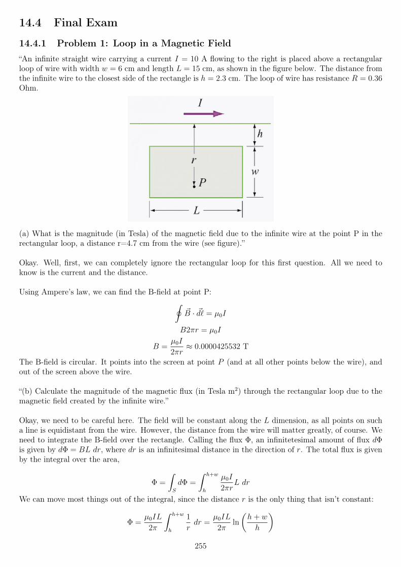
14.4 Final Exam
14.4.1 Problem 1: Loop in a Magnetic Field
“An infinite straight wire carrying a current I = 10 A flowing to the right is placed above a rectangularloop of wire with width w = 6 cm and length L = 15 cm, as shown in the figure below. The distance fromthe infinite wire to the closest side of the rectangle is h = 2.3 cm. The loop of wire has resistance R = 0.36Ohm.
(a) What is the magnitude (in Tesla) of the magnetic field due to the infinite wire at the point P in therectangular loop, a distance r=4.7 cm from the wire (see figure).”
Okay. Well, first, we can completely ignore the rectangular loop for this first question. All we need toknow is the current and the distance.
Using Ampere’s law, we can find the B-field at point P:∮~B · ~d` = µ0I
B2πr = µ0I
B =µ0I
2πr≈ 0.0000425532 T
The B-field is circular. It points into the screen at point P (and at all other points below the wire), andout of the screen above the wire.
“(b) Calculate the magnitude of the magnetic flux (in Tesla m2) through the rectangular loop due to themagnetic field created by the infinite wire.”
Okay, we need to be careful here. The field will be constant along the L dimension, as all points on sucha line is equidistant from the wire. However, the distance from the wire will matter greatly, of course. Weneed to integrate the B-field over the rectangle. Calling the flux Φ, an infinitetesimal amount of flux dΦis given by dΦ = BL dr, where dr is an infinitesimal distance in the direction of r. The total flux is givenby the integral over the area,
Φ =
∫S
dΦ =
∫ h+w
h
µ0I
2πrL dr
We can move most things out of the integral, since the distance r is the only thing that isn’t constant:
Φ =µ0IL
2π
∫ h+w
h
1
rdr =
µ0IL
2πln
(h+ w
h
)255
Φ ≈ 3.85004 · 10−7 T · m2
As a quick sanity check, what happens if we just multiply the B-field at P by the area of the rectangularloop (i.e. treat the B-field as constant throughout the loop)? The result should be somewhere in the sameorder of magnitude as the answer we just found. Doing that, we find 3.83 · 10−7 Tesla m2, which is quitereassuring! It looks like our integral is correct.
“(c) Suppose the current in the infinite wire starts increasing in time according to I = bt, with b = 60Amps/sec. What is the magnitude (in Amps) of the induced current in the loop? Neglect any contributionto the magnetic flux through the loop due to the magnetic field created by the induced current.”
The magnitude of the current will be given by
|I| = 1
R
dΦB
dt
which is really just Ohm’s law, using Faraday’s law to find the magnitude of the induced EMF (whichis equal to the rate of change of the magnetic flux through the loop’s “surface”). The magnetic field islinearly proportional to the current in the wire, and the magnetic flux through the loop is likewise linearlyproportional to the B-field (and thus the current).
We’ve already found Φ (or ΦB; I chose the shorter name earlier, but they are the same here):
ΦB =µ0IL
2πln
(h+ w
h
)Which variables here will change with regards to time? Assuming the loop doesn’t move (h is constant),only I can change. Therefore, when we take the time derivative, we find
dΦB
dt=dI
dt
µ0L
2πln
(h+ w
h
)We’ve given I = bt; b is constant, so the time derivative is
dI
dt= b = 60 A/s. Therefore, the above
expression withdI
dt= b A/s is the magnitude of the induced EMF. We only need to divide that by the
resistance of the loop to find the current:
Iind = bµ0L
2πRln
(h+ w
h
)Iind ≈ 6.4167 · 10−6 A
The direction of this current will be such that it opposes the increasing flux from the wire’s B-field. Theflux from the wire’s B-field increases into the page, so the our current must be induced to create flux outof the page, which means counterclockwise according to the right-hand rule.
14.4.2 Problem 2: Non-conducting infinite sheet and infinite parallel slab
“We have an infinite, non-conducting sheet of negligible thickness carrying a uniform surface charge density+σ = 2.00·10−6 C/m2 and, next to it, an infinite parallel slab of thickness D = 10 cm with uniform volumecharge density ρ = −1.60 · 10−5 C/m3 (see sketch). Note that the slab has a negative charge. All chargesare fixed in place and cannot move.”
256
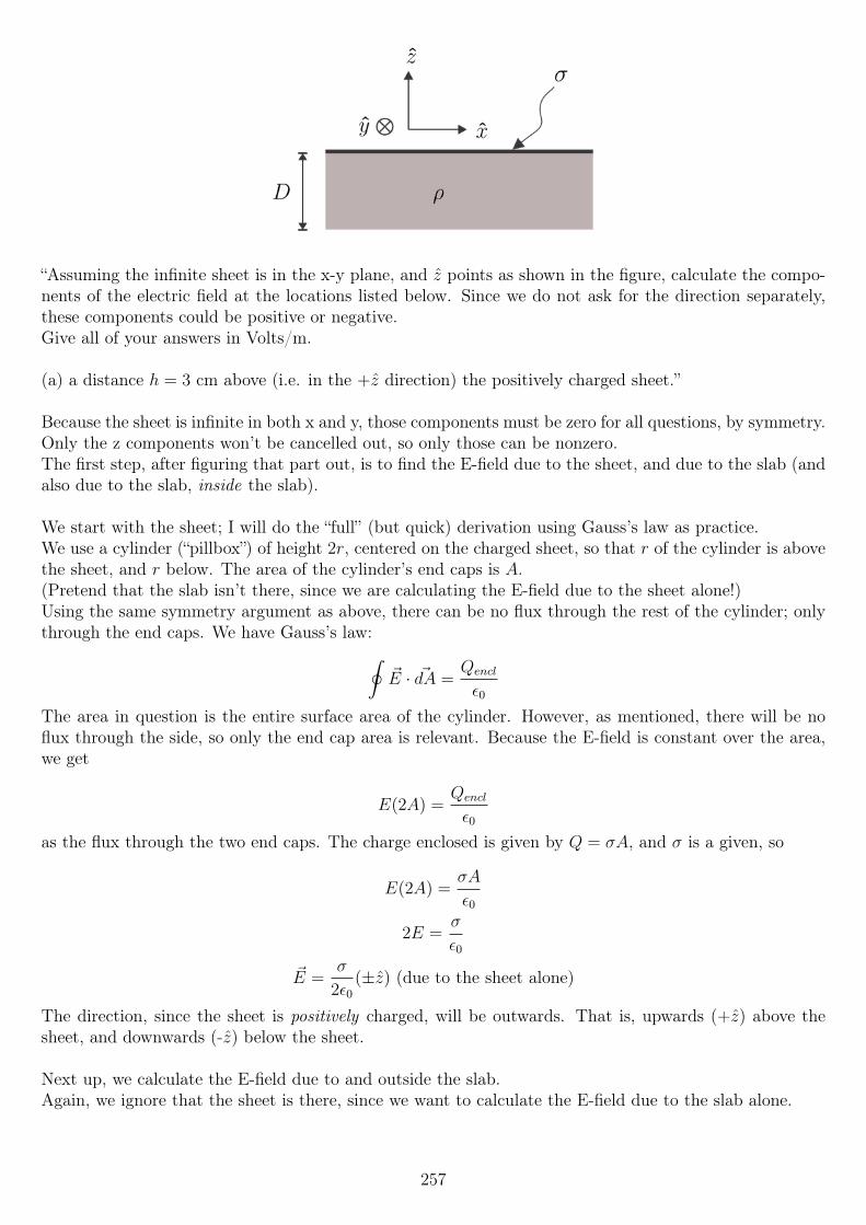
“Assuming the infinite sheet is in the x-y plane, and z points as shown in the figure, calculate the compo-nents of the electric field at the locations listed below. Since we do not ask for the direction separately,these components could be positive or negative.Give all of your answers in Volts/m.
(a) a distance h = 3 cm above (i.e. in the +z direction) the positively charged sheet.”
Because the sheet is infinite in both x and y, those components must be zero for all questions, by symmetry.Only the z components won’t be cancelled out, so only those can be nonzero.The first step, after figuring that part out, is to find the E-field due to the sheet, and due to the slab (andalso due to the slab, inside the slab).
We start with the sheet; I will do the “full” (but quick) derivation using Gauss’s law as practice.We use a cylinder (“pillbox”) of height 2r, centered on the charged sheet, so that r of the cylinder is abovethe sheet, and r below. The area of the cylinder’s end caps is A.(Pretend that the slab isn’t there, since we are calculating the E-field due to the sheet alone!)Using the same symmetry argument as above, there can be no flux through the rest of the cylinder; onlythrough the end caps. We have Gauss’s law:∮
~E · ~dA =Qencl
ε0
The area in question is the entire surface area of the cylinder. However, as mentioned, there will be noflux through the side, so only the end cap area is relevant. Because the E-field is constant over the area,we get
E(2A) =Qencl
ε0
as the flux through the two end caps. The charge enclosed is given by Q = σA, and σ is a given, so
E(2A) =σA
ε0
2E =σ
ε0
~E =σ
2ε0(±z) (due to the sheet alone)
The direction, since the sheet is positively charged, will be outwards. That is, upwards (+z) above thesheet, and downwards (-z) below the sheet.
Next up, we calculate the E-field due to and outside the slab.Again, we ignore that the sheet is there, since we want to calculate the E-field due to the slab alone.
257
We use a Gaussian “pillbox” again, again with end-cap area A (per cap). We again center the pillbox,and make it 2r high, such that 2r > D (the thickness). That is, the cylinder is higher than the slab andencloses the entire thickness of the slab, so to speak.
Using the same arguments as before, we will end up here again:
E(2A) =Qencl
ε0
The enclosed charge is now given by the volume V = AD, times the charge density (charge per unitvolume) ρ:
E(2A) =ADρ
ε0
E =Dρ
2ε0
~E =Dρ
2ε0(±z) (due the slab alone, outside the slab)
As the thickness decreases to where it no longer matters, this starts to look like the equation we have forthe thin sheet, which we would expect.
Finally, we do the calculation for the E-field inside the slab, due to the slab alone.Once again we use the pillbox, but this time we choose it such that r is much smaller than D, so thatit is completely inside the slab. We center it in the slab; the E-field should be exactly zero at the exactcenter, then grow linearly until the edge (since the charge density is constant) and then stay the sameuntil r →∞, since the E-field due to an infinite plane/slab doesn’t decay with distance.
Using Gauss’s law, we arrive at this step again:
E(2A) =Qencl
ε0
The charge enclosed is now given only by the size (volume) of our pillbox, V = 2rA (2r being the heightof the pillbox):
E(2A) =2rAρ
ε0
~E =rρ
ε0(±z)
So to summarize:
~E =σ
2ε0(±z) (due to the sheet alone)
~E =Dρ
2ε0(±z) (due the slab alone, outside the slab)
~E =rρ
ε0(±z) (due to the slab alone, inside the slab)
Let’s not forget that the slab is negatively charged !
Next, let’s gather together expressions for the E-fields above both, inside the slab, and below both.Above both, the E-field due to the sheet will point upwards (it is positively charged), and the E-field dueto the slab point downwards (it is negatively charged).The net E-field above is the superposition of the both, that is, the difference between the two, in this case:
258
~E = (σ
2ε0z) + (
Dρ
2ε0(−z))
~E = (σ
2ε0z)− (
Dρ
2ε0z)
Does this make intuitive sense? If σ “wins”, the field points upwards; if Dρ “wins”, it points downwards.Sounds good to me, so let’s simplify it down:
~E =σ −Dρ
2ε0z (above the sheet and slab)
Next up, we calculate the E-field below everything.Below both, the sheet’s E-field will point downward, and the slab’s upward.
~E = (σ
2ε0(−z)) + (
Dρ
2ε0z)
~E = (Dρ
2ε0z)− (
σ
2ε0z)
~E =Dρ− σ
2ε0z (below the sheet and slab)
Again, we check to make sure that it makes sense. If the sheet wins, the net field is now negative (down-wards), and it is positive (upwards) if the slab wins. This indeed makes sense, given their charge polarities.We note also that this is the opposite/negative of the E-field above both, which also makes sense.
Almost there... We need to find the combined E-field inside the slab, as well. Well, let’s see.(This is really a bit of overengineering: we don’t need this equation to solve it, we can just calculate it fora particular location, since the answer should be a number, not an expression.)There should be no sharp transitions when moving “through” the slab. At the very top, the E-field shouldbe the sum of that of the sheet and that outside (above) the slab. At the center, the slab’s E-field is zeroedout, and only the sheet’s should remain.At the very bottom, we should have the same value as below both. And this with a linear transisition.
Let’s have a look at this equation:
~E =rρ
ε0(±z) (due to the slab alone, inside the slab)
r will go from +0.5D to −0.5D as we move from top to bottom. We need to express this as d, a distancebelow the sheet (above the slab), which can then go from 0 at the top, to D at the bottom (and 0.5D inthe middle).r = 0.5D − d seems to fit nicely. Thus, we have
~E =(0.5D − d)ρ
ε0(±z) (due to the slab alone, inside the slab)
We can now also take care of the direction properly. Since the slab is negatively charged, the directionwill be downwards above the center, and upwards below the center.
~E =(0.5D − d)ρ
ε0(−z) (due to the slab alone, inside the slab)
We can finally calculate the net E-field inside the slab, by simply adding to this the E-field due to thesheet, which is downwards here (below the sheet):
~E =(0.5D − d)ρ
ε0(−z) +
σ
2ε0(−z)
259
~E = −(0.5D − d)ρ
ε0(z)− σ
2ε0z (inside the slab, total)
Again, a sanity check: for d = 0, the E-field due to the slab is downwards, at it should be, as is the E-fielddue to the sheet. For d = D, at the bottom of the two, the slab’s field turns positive:
E =Dρ
2ε0(z)
... which is the same equation that we found earlier. So we finally have the full set of equations:
~E =σ −Dρ
2ε0z (above the sheet and slab)
~E = −(0.5D − d)ρ
ε0(z)− σ
2ε0z (inside the slab)
~E =Dρ− σ
2ε0z (below the sheet and slab)
We can now plug in our values, and enter the answers as the z components, keeping all other componentszero. Keep the signs in mind!
“(a) a distance h = 3 cm above (i.e. in the +zˆ direction) the positively charged sheet.”
The distance doesn’t matter, but we plug in the values and find
Ez = 22588.2 V/m
σ > Dρ so this makes sense. Also, with σ = Dρ the answer is zero, which again makes sense.
“(b) inside the slab at a distance d = 1 cm below (i.e. in the −z direction) the positively charged sheet.Note that d < D so that this is also a distance 9 cm above the bottom of the slab.”
We plug it in again, and find
Ez = −185223 V/m
Both E-fields should be downward at this location, so a strong downwards value makes sense.
“(c) a distance H = 22 cm below (i.e. in the −z direction) the charged sheet. Note that H > D so thatthis is also a distance 12 cm below the bottom of the slab.”
Again, the distance doesn’t matter, but we plug the values in:
Ez = −22588.2 V/m
The answer is the negative of the one we found above the sheet, as it should be.
14.4.3 Problem 3: RLC circuit
“A circuit is composed of a capacitor C = 2µF, two resistors both with resistance R = 67 Ohm, an inductorL = 0.03 H, a switch S, and a battery V = 5 V. The internal resistance of the battery can be ignored.
260
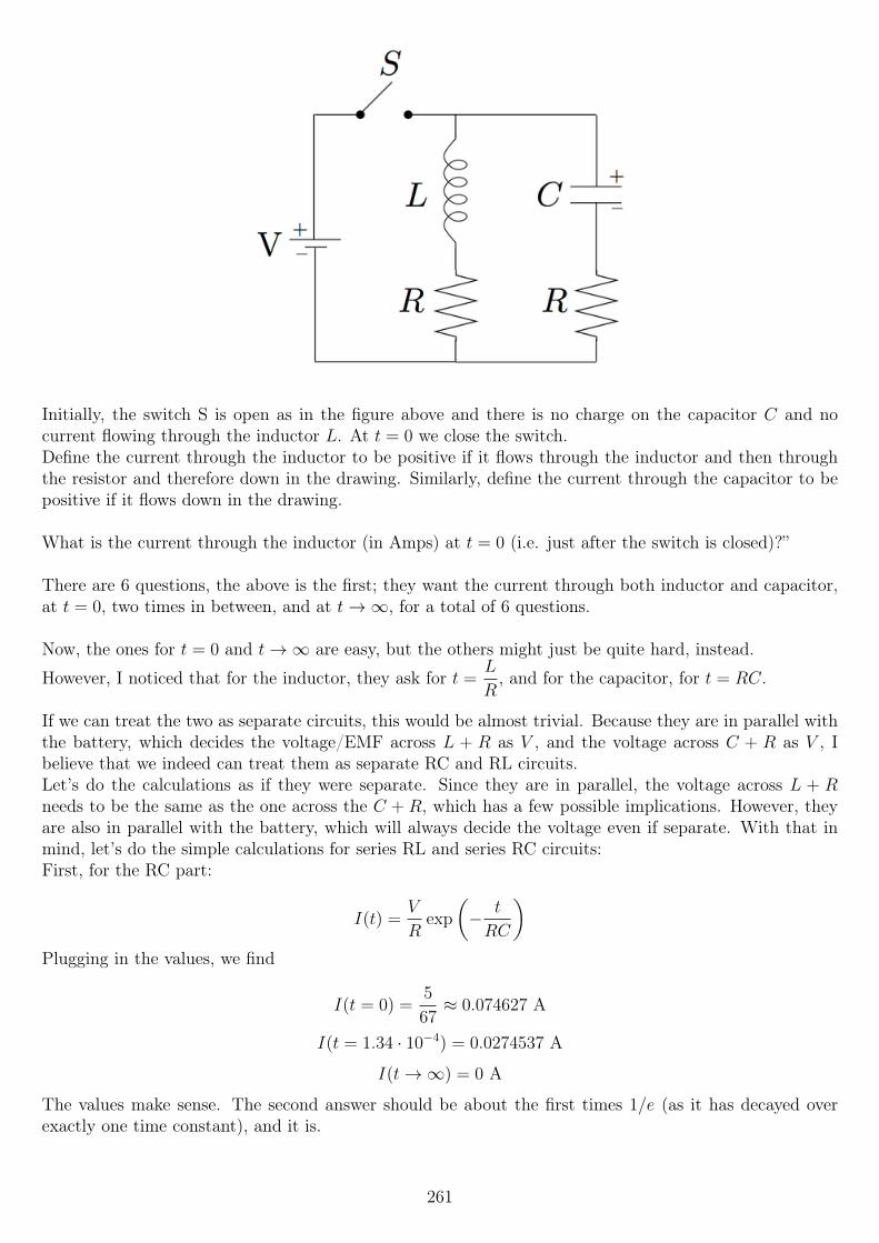
Initially, the switch S is open as in the figure above and there is no charge on the capacitor C and nocurrent flowing through the inductor L. At t = 0 we close the switch.Define the current through the inductor to be positive if it flows through the inductor and then throughthe resistor and therefore down in the drawing. Similarly, define the current through the capacitor to bepositive if it flows down in the drawing.
What is the current through the inductor (in Amps) at t = 0 (i.e. just after the switch is closed)?”
There are 6 questions, the above is the first; they want the current through both inductor and capacitor,at t = 0, two times in between, and at t→∞, for a total of 6 questions.
Now, the ones for t = 0 and t→∞ are easy, but the others might just be quite hard, instead.
However, I noticed that for the inductor, they ask for t =L
R, and for the capacitor, for t = RC.
If we can treat the two as separate circuits, this would be almost trivial. Because they are in parallel withthe battery, which decides the voltage/EMF across L + R as V , and the voltage across C + R as V , Ibelieve that we indeed can treat them as separate RC and RL circuits.Let’s do the calculations as if they were separate. Since they are in parallel, the voltage across L + Rneeds to be the same as the one across the C + R, which has a few possible implications. However, theyare also in parallel with the battery, which will always decide the voltage even if separate. With that inmind, let’s do the simple calculations for series RL and series RC circuits:First, for the RC part:
I(t) =V
Rexp
(− t
RC
)Plugging in the values, we find
I(t = 0) =5
67≈ 0.074627 A
I(t = 1.34 · 10−4) = 0.0274537 A
I(t→∞) = 0 A
The values make sense. The second answer should be about the first times 1/e (as it has decayed overexactly one time constant), and it is.
261
For the RL part:
I(t) =V
R
(1− exp
(−tLR
))I(t = 0) = 0 A
I(t = 4.48 · 10−4) = 0.0471878 A
I(t→∞) =5
67A
In this case, the second answer should be (1− 1/e) times the final one, and it is.
If these were two separate circuits, I would be very confident in these answers. As is, however, I’m onlyfairly confident in them.
However, considering that the 12th question on the exam, which is slightly similar, is ungraded in partdue to its difficulty (it was included as a “special challenge”), I would assume that this one is easier, andso I submitted these answers, and they were marked as correct.
14.4.4 Problem 4: Plane electromagnetic wave
“The electric and magnetic fields of a plane electromagnetic wave are given by the formulas below, wherez and λ are both in meters and t is in seconds. This wave is traveling through a medium whose index ofrefraction is 1.2.
~E = 8.6x sin(2π
λz + 5.91 · 1016t) V/m
~B = ~B0 sin(2π
λz + 5.91 · 1016t) Tesla
(a) In what direction does the wave propagate?”
The direction of propagation is given by the sign inside the sin function. In this case, it is −z due to the+z inside the sin.
“(b) What is the magnitude and direction of ~B0 (assuming B0 is positive)?”
E0 = B0v, where v is the propagation velocity. We can find v using the refractive index, as the definitionof n (here 1.2) is that
1.2 =c
v
1.2v = c
v =c
1.2
Therefore, since E0 = 8.6 V/m, and since we divide by v we flip the fraction upside down:
B0 = 8.6 · 1.2
c≈ 3.44 · 10−8 T
The direction must be such that E × B = v, that is, x× B = −z.Via the right-hand rule, that means that B = −y.
“(c) What is the wavelength of the wave (in meters)?”
262
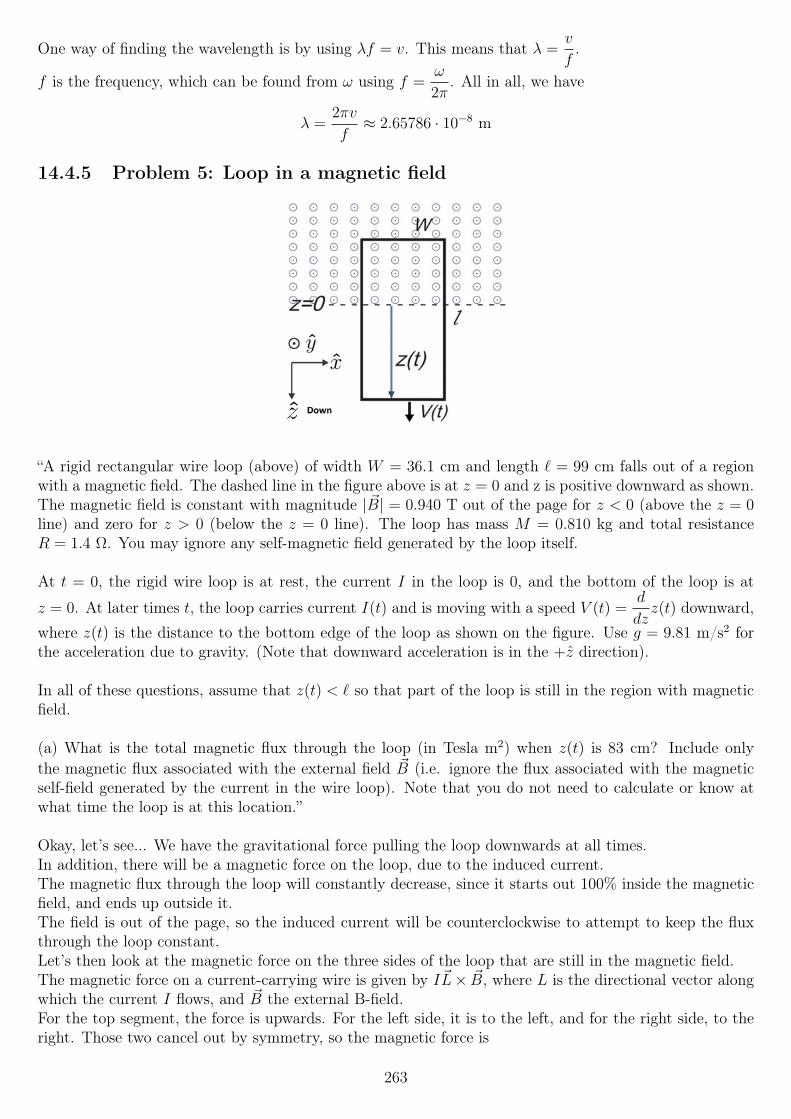
One way of finding the wavelength is by using λf = v. This means that λ =v
f.
f is the frequency, which can be found from ω using f =ω
2π. All in all, we have
λ =2πv
f≈ 2.65786 · 10−8 m
14.4.5 Problem 5: Loop in a magnetic field
“A rigid rectangular wire loop (above) of width W = 36.1 cm and length ` = 99 cm falls out of a regionwith a magnetic field. The dashed line in the figure above is at z = 0 and z is positive downward as shown.The magnetic field is constant with magnitude | ~B| = 0.940 T out of the page for z < 0 (above the z = 0line) and zero for z > 0 (below the z = 0 line). The loop has mass M = 0.810 kg and total resistanceR = 1.4 Ω. You may ignore any self-magnetic field generated by the loop itself.
At t = 0, the rigid wire loop is at rest, the current I in the loop is 0, and the bottom of the loop is at
z = 0. At later times t, the loop carries current I(t) and is moving with a speed V (t) =d
dzz(t) downward,
where z(t) is the distance to the bottom edge of the loop as shown on the figure. Use g = 9.81 m/s2 forthe acceleration due to gravity. (Note that downward acceleration is in the +z direction).
In all of these questions, assume that z(t) < ` so that part of the loop is still in the region with magneticfield.
(a) What is the total magnetic flux through the loop (in Tesla m2) when z(t) is 83 cm? Include onlythe magnetic flux associated with the external field ~B (i.e. ignore the flux associated with the magneticself-field generated by the current in the wire loop). Note that you do not need to calculate or know atwhat time the loop is at this location.”
Okay, let’s see... We have the gravitational force pulling the loop downwards at all times.In addition, there will be a magnetic force on the loop, due to the induced current.The magnetic flux through the loop will constantly decrease, since it starts out 100% inside the magneticfield, and ends up outside it.The field is out of the page, so the induced current will be counterclockwise to attempt to keep the fluxthrough the loop constant.Let’s then look at the magnetic force on the three sides of the loop that are still in the magnetic field.The magnetic force on a current-carrying wire is given by I~L× ~B, where L is the directional vector alongwhich the current I flows, and ~B the external B-field.For the top segment, the force is upwards. For the left side, it is to the left, and for the right side, to theright. Those two cancel out by symmetry, so the magnetic force is
263
~FB = IWB(−z) N (upwards)
There is then the downwards force by gravity. Since ~F = m~a and ~a = 9.81z m/s,
~Fg = 9.81 m/s2 · 0.81 kg = 7.95z N
We knowW and B, but need to calculate I in order to be able to find a numeric value for the upwards force.
First, let’s calculate the (external) flux through the surface of the loop, which will also answer the firstquestion.
The magnetic flux ΦB is given by the area inside the B-field, times the B-field strength:
ΦB = BW (`− z(t))
For z(t) = 83 cm, this is
ΦB = (0.940 T)(36.1 cm)(99 cm− 83 cm) = 0.0542944 T · m2
“(b) Using Faraday’s Law and Ohm’s Law, find the magnitude (in Amps) of the induced current I(t) inthe bar at the time when V = 9.00 m/sec. Note that you do not need to calculate or know at what timethe loop has this speed.”
We need to calculate the time derivative of the flux, which via Faraday’s Law gives us the induced EMF.We then divide that by the loop resistance, which will give us the magnituded of the current.
ΦB = BW (`− z(t))
ΦB = BW`−BWz(t)
dΦB
dt= −BWV (t)
The negative of this is the induced EMF. We’re asked for the magnitude, so we don’t really care aboutminus signs, but still. We divide this by the loop resistance to find the current:
I(t) =BWV (t)
R≈ 2.18147 A
... where the approximation is for V (t) = 9 m/s, as they asked for in part (b).
“(c) Which way does the current flow around the loop, clockwise or counterclockwise?”
Counterclockwise; we answered that long ago.
“(d) What is the total magnetic force (in Newtons) on the rigid wire loop when V=9.00 m/sec? Again,ignore any effects due to the self magnetic field.”
Now that we know the current, we can calculate this.
| ~FB| = IWB = (2.18147 A)(36.1/100 m)(0.940 T) = 0.74026 N
The direction is upwards, as stated earlier.
“(e) What is the magnitude of the terminal speed (in m/sec) of the loop (i.e. the speed at which the loopwill be moving when it no longer accelerates)?”
264
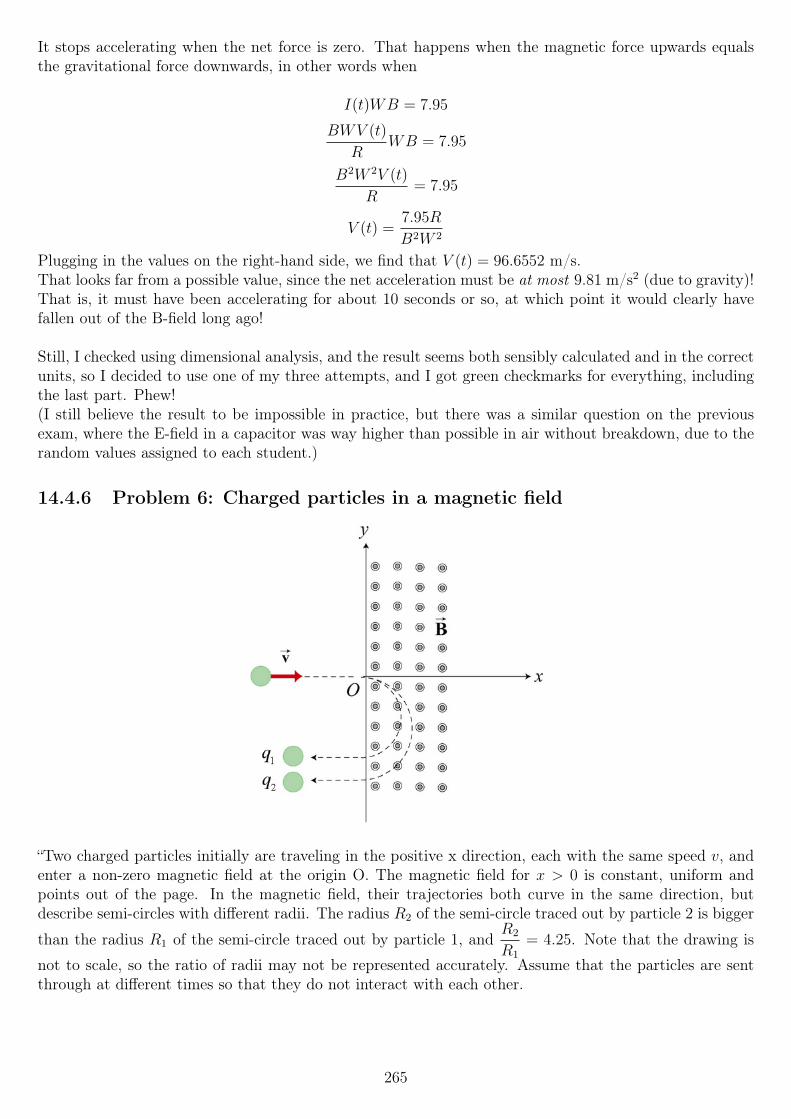
It stops accelerating when the net force is zero. That happens when the magnetic force upwards equalsthe gravitational force downwards, in other words when
I(t)WB = 7.95
BWV (t)
RWB = 7.95
B2W 2V (t)
R= 7.95
V (t) =7.95R
B2W 2
Plugging in the values on the right-hand side, we find that V (t) = 96.6552 m/s.That looks far from a possible value, since the net acceleration must be at most 9.81 m/s2 (due to gravity)!That is, it must have been accelerating for about 10 seconds or so, at which point it would clearly havefallen out of the B-field long ago!
Still, I checked using dimensional analysis, and the result seems both sensibly calculated and in the correctunits, so I decided to use one of my three attempts, and I got green checkmarks for everything, includingthe last part. Phew!(I still believe the result to be impossible in practice, but there was a similar question on the previousexam, where the E-field in a capacitor was way higher than possible in air without breakdown, due to therandom values assigned to each student.)
14.4.6 Problem 6: Charged particles in a magnetic field
“Two charged particles initially are traveling in the positive x direction, each with the same speed v, andenter a non-zero magnetic field at the origin O. The magnetic field for x > 0 is constant, uniform andpoints out of the page. In the magnetic field, their trajectories both curve in the same direction, butdescribe semi-circles with different radii. The radius R2 of the semi-circle traced out by particle 2 is bigger
than the radius R1 of the semi-circle traced out by particle 1, andR2
R1
= 4.25. Note that the drawing is
not to scale, so the ratio of radii may not be represented accurately. Assume that the particles are sentthrough at different times so that they do not interact with each other.
265
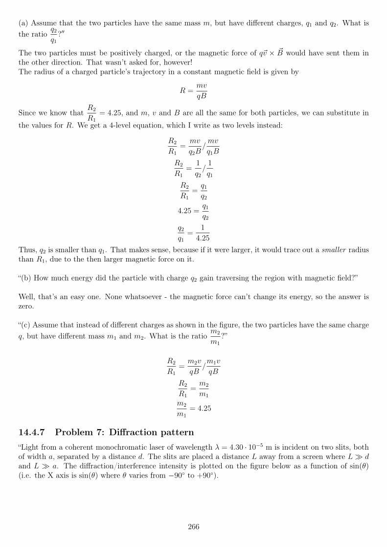
(a) Assume that the two particles have the same mass m, but have different charges, q1 and q2. What isthe ratio
q2
q1
?′′
The two particles must be positively charged, or the magnetic force of q~v × ~B would have sent them inthe other direction. That wasn’t asked for, however!The radius of a charged particle’s trajectory in a constant magnetic field is given by
R =mv
qB
Since we know thatR2
R1
= 4.25, and m, v and B are all the same for both particles, we can substitute in
the values for R. We get a 4-level equation, which I write as two levels instead:
R2
R1
=mv
q2B/mv
q1B
R2
R1
=1
q2
/1
q1
R2
R1
=q1
q2
4.25 =q1
q2
q2
q1
=1
4.25
Thus, q2 is smaller than q1. That makes sense, because if it were larger, it would trace out a smaller radiusthan R1, due to the then larger magnetic force on it.
“(b) How much energy did the particle with charge q2 gain traversing the region with magnetic field?”
Well, that’s an easy one. None whatsoever - the magnetic force can’t change its energy, so the answer iszero.
“(c) Assume that instead of different charges as shown in the figure, the two particles have the same chargeq, but have different mass m1 and m2. What is the ratio
m2
m1
?”
R2
R1
=m2v
qB/m1v
qB
R2
R1
=m2
m1
m2
m1
= 4.25
14.4.7 Problem 7: Diffraction pattern
“Light from a coherent monochromatic laser of wavelength λ = 4.30 · 10−5 m is incident on two slits, bothof width a, separated by a distance d. The slits are placed a distance L away from a screen where L dand L a. The diffraction/interference intensity is plotted on the figure below as a function of sin(θ)(i.e. the X axis is sin(θ) where θ varies from −90 to +90).
266
“Based on the plot of intensity versus sin(θ) in the figure above,(a) what is a in m?”
Let’s see... This combined diffraction+interference pattern might be the weakest point of my knowledgeof the entire 8.02x material.I recall that the interference pattern is the one with many small peaks, while the diffraction pattern isthe envelope. That is, the diffraction pattern (not really drawn as-is) has one large peak, from about−0.5 < sin θ < 0.5, with one secondary peak on each side of that.
For single-slit diffraction, we have the first minima at
sin θ =λ
a(destructive interference, single-slit diffraction)
267
The first maximum is at the center, sin θ = θ = 0, and has a width of sin(∆θ) ≈ λ
a, which is the first
minima.
For double-slit interference, we have one maximum at the center, as always, and other maxima at
sin θn =nλ
d(constructive interference, double-slit interference)
sin θn =(2n+ 1)λ
2d(destructive interference, double-slit interference)
So the diffraction causes the envelope, which has a width of ∆θ (from 0 to the first minima) which looksto be about sin θ = 0.43 or something like that. So we have
0.43 =λ
a
a =λ
0.43=
4.30 · 10−5
0.43= 10−4 m
... which is incorrect! (The value for d below was correct, however.)I tried again with sin θ ≈ 0.5, and got it correct! That’s a bit disappointing in a way, though: my methodwas correct, but the estimation was off. Since it’s not marked explicitly on the graph, I’m sure severalstudents will get this one wrong twice (there are two tries for this question) based on estimation errors alone.
As for the interference part of it all, we have the first-order maximum at approximately sin θ = 0.12 (Ihope the grader allows for a wide margin of error!), so we have
0.12 =λ
d
d =λ
0.12=
4.30 · 10−5
0.12= 3.5833 · 10−4 m
I had another quick look in the book (since this is an open book exam; I only use it to check smaller stuff,though), to find the horrible equation for the intensity plot. It is
I = I0 cos2(πd sin θ/λ)
[sin(πa sin θ/λ)
πa sin θ/λ)
]2
I plotted I/I0 using this function, to see whether the plot was anything like this, and it looked fairlysimilar... However I had θ as the x axis, while the book had sin θ, so an exact comparison wasn’t possible.I’m not sure how to plot with sin θ as the x axis in Mathematica, so I skipped that.
14.4.8 Problem 8: Capacitor washers
“A capacitor consists of two identical metal washers of inner radius a = 1.4 mm and outer radius b = 5.1mm, separated by a distance d = 0.19 mm (note that b d). The capacitor is initially uncharged at t = 0and we then begin to charge it using wires outside the plates that are not shown in the figure. Supposeat time t the charge on the lower washer is Q(t) = st with s = 19µC/sec and that this charge is spreaduniformly over the area of the bottom washer.The top washer has an identical, but negative, charge −Q(t), also distributed uniformly. Throughoutthis problem you may assume that the electric field is non-zero only inside the capacitor over the rangea < r < b, where r is the cylindrical radial distance.You may also assume that, in the regions where the electric field is non-zero, it points exactly perpendicularto the surface of the washers (i.e. upward as shown) and has the same magnitude at all locations (but themagnitude varies with time).”
268
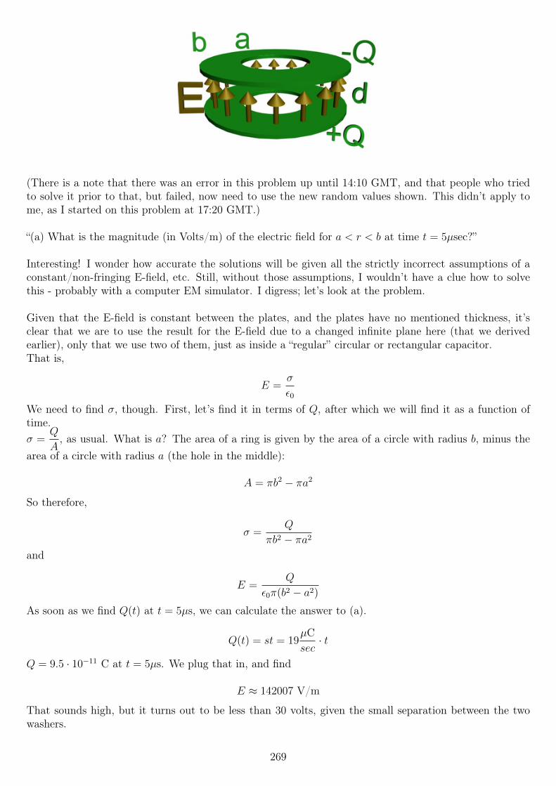
(There is a note that there was an error in this problem up until 14:10 GMT, and that people who triedto solve it prior to that, but failed, now need to use the new random values shown. This didn’t apply tome, as I started on this problem at 17:20 GMT.)
“(a) What is the magnitude (in Volts/m) of the electric field for a < r < b at time t = 5µsec?”
Interesting! I wonder how accurate the solutions will be given all the strictly incorrect assumptions of aconstant/non-fringing E-field, etc. Still, without those assumptions, I wouldn’t have a clue how to solvethis - probably with a computer EM simulator. I digress; let’s look at the problem.
Given that the E-field is constant between the plates, and the plates have no mentioned thickness, it’sclear that we are to use the result for the E-field due to a changed infinite plane here (that we derivedearlier), only that we use two of them, just as inside a “regular” circular or rectangular capacitor.That is,
E =σ
ε0
We need to find σ, though. First, let’s find it in terms of Q, after which we will find it as a function oftime.σ =
Q
A, as usual. What is a? The area of a ring is given by the area of a circle with radius b, minus the
area of a circle with radius a (the hole in the middle):
A = πb2 − πa2
So therefore,
σ =Q
πb2 − πa2
and
E =Q
ε0π(b2 − a2)
As soon as we find Q(t) at t = 5µs, we can calculate the answer to (a).
Q(t) = st = 19µCsec· t
Q = 9.5 · 10−11 C at t = 5µs. We plug that in, and find
E ≈ 142007 V/m
That sounds high, but it turns out to be less than 30 volts, given the small separation between the twowashers.
269
Oh, that was the next question!
“(b) What is the magnitude (in Volts) of the electrostatic potential difference between the washers at thesame time t = 5µsec?”
V = Ed
V = (142007 V/m)(0.19 · 10−3 m) ≈ 26.981 V
“(c) What is the capacitance (in Farads) of this arrangement of conductors?”
By definition,
C =Q
V
As a symbolic answer,
C =s td s t
ε0π(b2−a2)
=s tε0π(b2 − a2)
d s t
C =ε0π(b2 − a2)
d
Very nice. Another definition of capacitance is
C =Aε0d
... which is exactly what we found above!We plug in the numbers, and find
C ≈ 3.52095 · 10−12 F
Very tiny, as expected with almost no area, and no dielectric.
“(d) What is the magnitude of the magnetic field (in Tesla) inside the capacitor at a radius r = 3.4 mmand at time t = 5µs?”
Ah, that’s a fairly painful calculation for a mere sub-question!I could look back in my notes to find an equation for the B-field, but I will re-derive it as I have done withmost things so far.
We’ll need to use the Ampere-Maxwell law:∮~B · ~d` = µ0
(Ipen + ε0
dΦE
dt
)We choose our Amperean loop to be a circle, concentric with the washers, of course. We center it exactlybetween the plates (though that should not matter), and attach a flat surface to it.
Zero “real” current will penetrate that surface, since it is mid-air. There will however be a displacementcurrent, that is, a change in electric flux, as the capacitor is being charged.The left-hand side of the equation should be easy, since we will assume the B-field to be constant alongthe circle. We simplify the equation to
B(2πr) = µ0ε0dΦE
dt
270
B =µ0ε02πr
dΦE
dt
Next up, we calculate the electric flux ΦE. Let’s not forget that there is a big hole in the center of thecapacitor, unlike previous times we’ve done a similar calculation!
ΦE = EA =st
ε0π(b2 − a2)A
What is A here, then? Again, let’s be careful. We have a ring; the outer radius is r, the radius of theAmperean loop, which is smaller than b (the outer radius of the capacitor) and larger than a (the innerradius).The inner radius is a. Thus A = πr2 − πa2, and
ΦE =st
ε0π(b2 − a2)(πr2 − πa2)
ΦE =st
ε0π(b2 − a2)π(r2 − a2)
ΦE =st(r2 − a2)
ε0(b2 − a2)
Next, we take the time derivative. The charge is Q = st, so the time derivative of that is I = s. s is givento us in microcoulombs per second, which is the same as microamperes.Alternatively, we can just take the derivative with respect to t of the above expression, and we get thesame result. That is,
dΦE
dt=
s(r2 − a2)
ε0(b2 − a2)
We can then calculate the B-field, since this term was the only thing missing:
B =µ0ε02πr
s(r2 − a2)
ε0(b2 − a2)
B =µ0s
2πr
r2 − a2
b2 − a2
B ≈ 4.46129 · 10−10 (for r = 3.4 mm)
Time for a sanity check! If we use this method to calculate the B-field for r = b, and also use
B =µ0I
2πr(B-field for an infinite wire)
... the results should be identical. We don’t even need to put numbers in there, because when you setr = b, it simplifies down to that instantly! Awesome.
“(e) What is the magnitude of the Poynting vector (in Watts/m2) at radius r = b and at time t = 5µs?”
The Poynting vector ~S is given by
~S =~E × ~B
µ0
Making the substitutions (also, keep in mind that I = s),
~S =1
µ0
(Q
ε0π(b2 − a2)
)(µ0I
2πr
)271
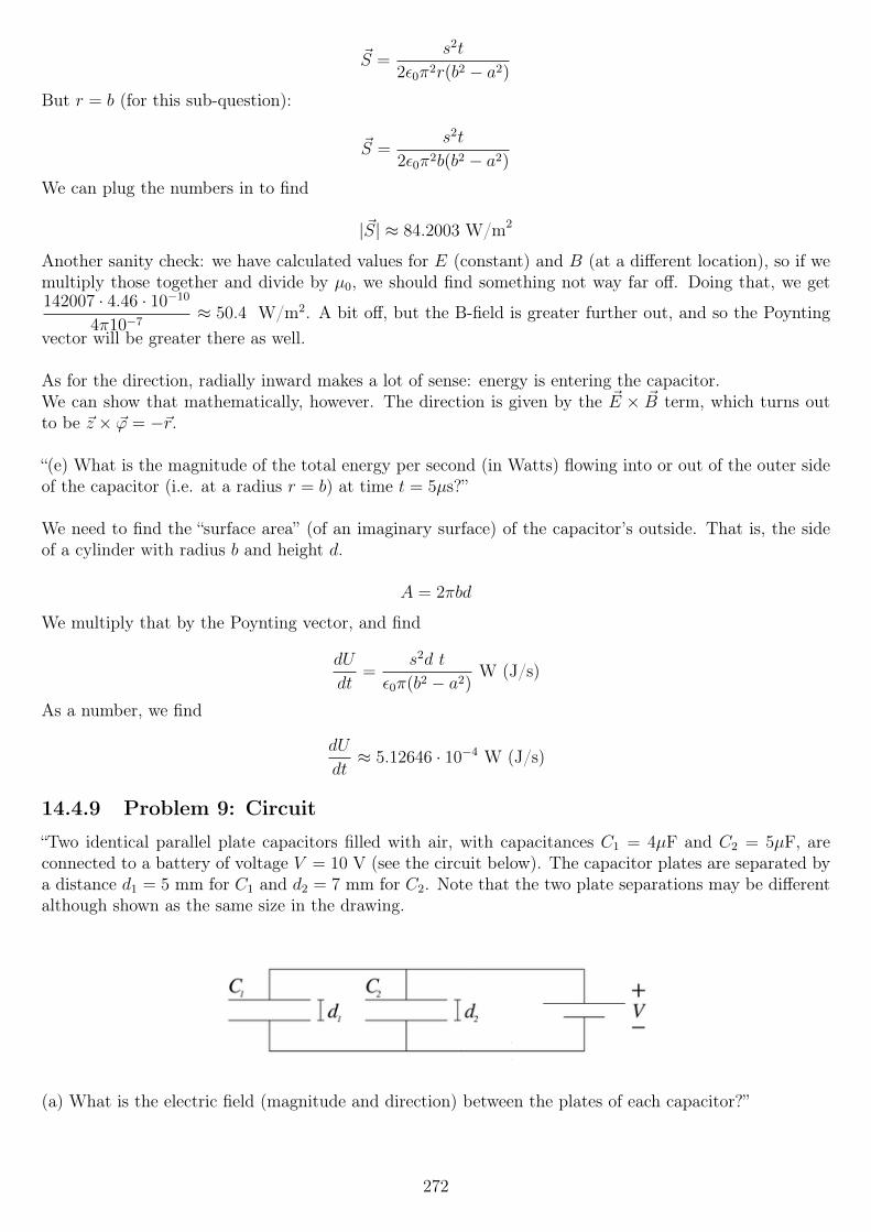
~S =s2t
2ε0π2r(b2 − a2)
But r = b (for this sub-question):
~S =s2t
2ε0π2b(b2 − a2)
We can plug the numbers in to find
|~S| ≈ 84.2003 W/m2
Another sanity check: we have calculated values for E (constant) and B (at a different location), so if wemultiply those together and divide by µ0, we should find something not way far off. Doing that, we get142007 · 4.46 · 10−10
4π10−7≈ 50.4 W/m2. A bit off, but the B-field is greater further out, and so the Poynting
vector will be greater there as well.
As for the direction, radially inward makes a lot of sense: energy is entering the capacitor.We can show that mathematically, however. The direction is given by the ~E × ~B term, which turns outto be ~z × ~ϕ = −~r.
“(e) What is the magnitude of the total energy per second (in Watts) flowing into or out of the outer sideof the capacitor (i.e. at a radius r = b) at time t = 5µs?”
We need to find the “surface area” (of an imaginary surface) of the capacitor’s outside. That is, the sideof a cylinder with radius b and height d.
A = 2πbd
We multiply that by the Poynting vector, and find
dU
dt=
s2d t
ε0π(b2 − a2)W (J/s)
As a number, we find
dU
dt≈ 5.12646 · 10−4 W (J/s)
14.4.9 Problem 9: Circuit
“Two identical parallel plate capacitors filled with air, with capacitances C1 = 4µF and C2 = 5µF, areconnected to a battery of voltage V = 10 V (see the circuit below). The capacitor plates are separated bya distance d1 = 5 mm for C1 and d2 = 7 mm for C2. Note that the two plate separations may be differentalthough shown as the same size in the drawing.
(a) What is the electric field (magnitude and direction) between the plates of each capacitor?”
272
So they are “identical”, but differ in capacitance and plate separation? Hmm... Strange wording.In fact, if we solve for the area, they differ in area too! How the heck are they identical, exactly?!Ah well, I will assume that this is simply an oversight, and that the word “identical” should really beremoved...
Well then. We know that
E1 =σ1
ε0
E2 =σ2
ε0
... but we do not know the charge density, nor do we know the charge.We can also find it as
E1 =V
d1
E2 =V
d2
V is the same for both capacitors, as they are connected in parallel. Since there is a battery connected,which decides V , we can just plug the numbers in at this point.
E1 = 2000 V/m
E2 ≈ 1428.57 V/m
Both E-fields are pointed downward, since the positive plate is on top.
“We fill the entire air gap of C1, the capacitor on the left, with a dielectric having κ = 4.0 while keepingthe battery connected.
(b) What now is the electric field (direction and magnitude) between the plates of each capacitor?”
We must not forget (or miss) that the battery is still connected! The potential difference will still be Vacross each capacitor; that simply cannot change!
The E-field inside is constant at all places inside, with or without a dielectric. Some equations that alwaysapply are
C =Q
V
V =Q
C
V = Ed
C =ε0A
dκ
Because d is fixed and V is fixed, E must be fixed at
E =V
d
for both capacitors. That is
E1 =V
d1
= 2000 V/m
273
E2 =V
d2
≈ 1428.57 V/m
... exactly as before. This is because the battery is connected, which forces V to stay unchanged.
“(c) Suppose that we disconnect the battery before filling the entire air gap of C1, the capacitor onthe left, with a dielectric having κ = 4.0. When disconnecting the battery, we leave the two capacitorsconnected to each other as shown. After the dielectric is put in (and the battery remains discon-nected), what would the electric field be between the plates of each capacitor (direction and magnitude)?”
What happens now is that V can change (but must still be the same for both capacitors), while Q on the ca-pacitors can vary. The total change must still equal the total change that was there to begin with, however.
We know that
Q = CV
So
Q1 = C1V = 4 · 10−5 C
Q2 = C2V = 5 · 10−5 C
... before the dielectric is inserted! Thus, Qinitial = 9 · 10−5 C; this is the total charge on both capacitors,which must be held constant once the battery is removed.
A new set of equations that must hold true now:
Q1 +Q2 = Qinitial
C1new =Q1
V= κC1
C2 =Q2
V
Because of the inserted dielectric, C1new = κC1, where C1 is the old, original capacitance.
We can combine the above equations, and solve for V :
V (C1new + C2) = Qinitial
V =Qinitial
C1new + C2
We now have that in terms of variables we know. Finally, the electric field is given by
E =V
d
so that
E =Qinitial
d(C1new + C2
)
E =Qinitial
d(κC1 + C2
)
Plugging in the numbers, keeping in mind that d varies between the capacitors:
E1 =6000
7≈ 857.143 V/m
274
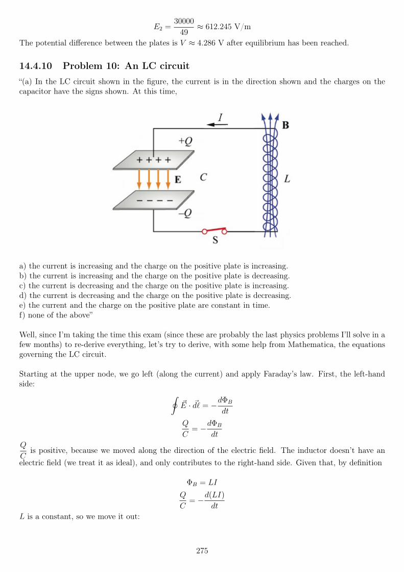
E2 =30000
49≈ 612.245 V/m
The potential difference between the plates is V ≈ 4.286 V after equilibrium has been reached.
14.4.10 Problem 10: An LC circuit
“(a) In the LC circuit shown in the figure, the current is in the direction shown and the charges on thecapacitor have the signs shown. At this time,
a) the current is increasing and the charge on the positive plate is increasing.b) the current is increasing and the charge on the positive plate is decreasing.c) the current is decreasing and the charge on the positive plate is increasing.d) the current is decreasing and the charge on the positive plate is decreasing.e) the current and the charge on the positive plate are constant in time.f) none of the above”
Well, since I’m taking the time this exam (since these are probably the last physics problems I’ll solve in afew months) to re-derive everything, let’s try to derive, with some help from Mathematica, the equationsgoverning the LC circuit.
Starting at the upper node, we go left (along the current) and apply Faraday’s law. First, the left-handside: ∮
~E · ~d` = −dΦB
dt
Q
C= −dΦB
dt
Q
Cis positive, because we moved along the direction of the electric field. The inductor doesn’t have an
electric field (we treat it as ideal), and only contributes to the right-hand side. Given that, by definition
ΦB = LI
Q
C= −d(LI)
dt
L is a constant, so we move it out:
275
Q
C= −LdI
dt
We can write it all in terms of Q, by making the substitution I =dQ
dt:
Q
C= −Ld
2Q
dt2
That’s about all we can do. We could rewrite it to have all terms on the left side, but since I’m not goingto solve this differential equation manually, it hardly matters.I solved it using the boundary conditions Q(0) = Q0 and Q′(0) = 0, that is: initial charge Q0 on thecapacitor, and zero current at t = 0. The current through a capacitor is maximum while it is beingcharged, but zero when the charge (and voltage across it) is at the maximum.The solution is
Q(t) = Q0 cos
(t√LC
)Based on the definition C =
Q
V, V =
Q
C:
VC(t) =Q0
Ccos
(t√LC
)Finally, the current is given by the time derivative of the charge:
I(t) = − Q0√LC
sin
(t√LC
)Using
I0 =Q0√LC
I(t) = −I0 sin
(t√LC
)Let’s think about signs for a second. I recall getting this backwards previously, and I had a quick look in
the book (this is an open-book exam after all); indeed, they use I = −dQdt
here. Let’s see if that makesmore sense.In our equations, when Q0 has just reached its maximum and starts decreasing, that means that, usingthe signs in the figure above, the current is clockwise, which is indeed negative as shown. I’ll stick withthe convention I just found, as that seems less confusing than ignoring the arrows as drawn.
OK, so with these equations in mind, is the first question now easier to answer?What do we know from the picture? The current is flowing “into” the positive plate (counterclockwise).This must mean that the charge is increasing, since that would “deposit” positive charge on the top plate.
That leaves options (a), (c) and (f), none of the above.Is the current increasing or decreasing? We’ve established that the charge must be increasing (on thepositive plate). If we plot the two (just plot y = cos(x) for the charge and y = −sin(x) for the current)we see that when the charge is increasing (that is, is above y = 0 and has positive slope), in such a plotbetween x = π and x = 3π
2, the current is decreasing.
That also makes intuitive sense, if we know how these circuits work. As the charge is zero and startsincreasing, the current is at a maximum. The charge keeps increasing, and the current decreasing, untilthe charge reaches a maximum.
276
Thus, the answer is (c).
“For the following questions, assume that the inductance is 0.05 H, the capacitance is 4 µF, and the max-imum magnitude of the current in the circuit is 90 milliAmps.
(b) How many times per second will the magnitude of the current have this maximum value?”
Let’s see. First, they ask about the magnitude of the current, so this maximum happens more than onceper cycle!
I(t) ∝ sin
(t√LC
)The term multiplying the sine doesn’t charge the period in any way, so we can ignore it for now. All wewant to know is how often this function is either +1 or −1, which is when the current’s magnitude is at amaximum.This is twice per period, so we can calculate the frequency, and just double that.The angular oscillation frequency is
ω0 =1√LC
We can convert this to a “regular” frequency in hertz using f =ω
2π:
f =ω
2π=
1
2π√LC
We wanted twice this value though, so the answer is
# maxima per second = 2f =1
π√LC≈ 711.763 Hz
“(c) The energy stored in the capacitor oscillates up and down as a function of time. What is the magni-tude of the difference (in Joules) between the largest and smallest amounts of energy ever stored in thecapacitor?”
I don’t like how that is phrased... It oscillates between 0 and a maximum, so I assume the answer is thesame as the maximum energy stored, then?
In an LC circuit, all energy sloshes back and forth between the inductor and capacitor. This means thatwe don’t have to calculate the capacitor’s energy, but we can instead calculate the inductor’s and use thatas the answer.Doing so is easier, because they gave us I0 = 90 mA.
Umax =1
2LI0
2 ≈ 2.025 · 10−4 J
Let’s verify that, though - this is the final exam!
We can calculate the maximum stored energy in the capacitor using U =1
2
Q2
C.
The maximum charge can be found by using the given value of I0.
I0 =Q0√LC
Q0 = I0
√LC ≈ 4.02492 · 10−5 C
Therefore,
277
Umax =1
2
(4.02492 · 10−5)2
4 · 10−6≈ 2.025 · 10−4 J
Looks good!
“(d) What is the time averaged power (in Watts) flowing into or out of the self inductor over 3 full cycles?Define power into the inductor as positive.”
In one cycle, a certain amount of energy will both enter and leave, which nets 0 energy per cycle. Thusthe time-average power over any amount of full cycles is zero.
14.4.11 Problem 11: Dielectric sphere
“Consider a dielectric spherical shell with inner radius 1 cm and outer radius R = 15 cm. The sphericalshell is filled with dielectric with electric permittivity κ = 4.0 and there is a point charge q = 2.3 µCexactly at its center, which we consider the origin of our reference frame.
Calculate the direction and the magnitude of the electric field for the following points:(a) What is the direction [and magnitude] of the electric field at the point whose distance from the originis 11 cm?”
To clarify, there is a (very thick) “shell” (almost “sphere”, but there is a spherical void in the center) madeof a dielectric with the given value of κ, and a small spherical hole in the center, with a radius of only 1 cm.
First, using Coulomb’s law, the E-field due to the point change, in a vacuum, is
~E =q
4πε0r2r (in vacuum)
... where r is the unit vector pointing radially outwards from the charge. The above equation is only validinside a vacuum, however. At the point where they ask for the E-field, we are inside the dielectric.A dielectric lowers the E-field below that of the vacuum field, by a factor κ. That is, inside the dielectric:
~E =q
4πκε0r2r (in the dielectric)
Plugging in the numbers, we find
~E ≈ 427094 r V/m
“(b) What is the direction [and magnitude] of the electric field at the point whose distance from the originis 15 cm?”
Again, plugging in the numbers, we find E ≈ 229682 V/m... IF this is still inside the dielectric, otherwiseκ times that! Ugh.I tried submitting that answer, and it came back wrong. I tried again with κ times the value (E ≈ 918728V/m), and that was correct, so the intention was that 15 cm is exactly outside the dielectric, not insideexactly on the edge.
“(c) What is the total net charge (in Coulombs) contained in the dielectric (i.e. not counting the pointcharge) inside a radius r of 11 cm?”
This is the only question I missed on this exam, so this answer is written after looking at the staff’sanswers.My first try was zero, because charge can’t flow freely inside the dielectric, but that was incorrect.
278
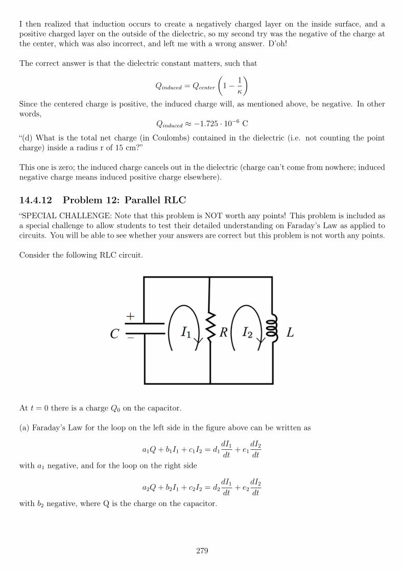
I then realized that induction occurs to create a negatively charged layer on the inside surface, and apositive charged layer on the outside of the dielectric, so my second try was the negative of the charge atthe center, which was also incorrect, and left me with a wrong answer. D’oh!
The correct answer is that the dielectric constant matters, such that
Qinduced = Qcenter
(1− 1
κ
)Since the centered charge is positive, the induced charge will, as mentioned above, be negative. In otherwords,
Qinduced ≈ −1.725 · 10−6 C
“(d) What is the total net charge (in Coulombs) contained in the dielectric (i.e. not counting the pointcharge) inside a radius r of 15 cm?”
This one is zero; the induced charge cancels out in the dielectric (charge can’t come from nowhere; inducednegative charge means induced positive charge elsewhere).
14.4.12 Problem 12: Parallel RLC
“SPECIAL CHALLENGE: Note that this problem is NOT worth any points! This problem is included asa special challenge to allow students to test their detailed understanding on Faraday’s Law as applied tocircuits. You will be able to see whether your answers are correct but this problem is not worth any points.
Consider the following RLC circuit.
At t = 0 there is a charge Q0 on the capacitor.
(a) Faraday’s Law for the loop on the left side in the figure above can be written as
a1Q+ b1I1 + c1I2 = d1dI1
dt+ e1
dI2
dt
with a1 negative, and for the loop on the right side
a2Q+ b2I1 + c2I2 = d2dI1
dt+ e2
dI2
dt
with b2 negative, where Q is the charge on the capacitor.
279
Express all the coefficients above (a1, b1, c1, d1, e1, a2, b2, c2, d2, e2 in terms of R, L, C and naturalconstants.”
This looks scary, but many of the coefficients will be zero, from the looks of it.Still, scored question or not, having solved the rest of the exam (expect for 11c which I missed), I will ofcourse give this a try.
To get a1 negative, we go in the clockwise direction, as the arrow suggests. We find
−QC
+ I1R− I2R = 0
That is,
a1 = − 1
C
b1 = R
c1 = −R
d1 = 0
e1 = 0
For the right loop, we need to use Faraday’s law, since there is an inductor present. We also want to getb2 negative, so we again go clockwise for that to happen. Starting at the bottom:
−I1R + I2R = −dΦB
dt
The last term, the change in magnetic flux, is given by the definition of inductance, and the current I2
through the inductor:
−I1R + I2R = −LdI2
dt
To get this result in term of the coefficients, we need
a2 = 0
b2 = −R
c2 = R
d2 = 0
e2 = −L
“(b) What isdQ
dtequal to? Your answer can include only one or both of I1 and I2 and numbers.”
The change in charge of the capacitor is equal to the current through it - whether it is positive or negativeis the only thing we really need to consider.
SaydQ
dt> 0, so that the charge is increasing. The way I would see this is that the current is counterclock-
wise, so that charge increases on the top plate, here marked as positive.Therefore, the answer should be −I1 (it is opposite of the marked current).
“(c) The charge on the capacitor obeys the following differential equation:
d2Q
dt2+ a
dQ
dt+ bQ = 0
280
Express a and b in terms of, if necessary, R, L and C.”
Let’s try to apply KCL for the top node, summing the current leaving (going downwards). Because thevoltage across all elements must be the same (they are in parallel), I call the voltage across each elementVC(t), i.e. the voltage across the capacitor.
CdVC(t)
dt+VC(t)
R+
1
L
∫ t
0
VC(t)dt = 0
(assuming IL(0) = 0, or the integral needs to be from −∞)
Because VC(t) =Q(t)
C, we can rewrite this:
Cd
dt
(Q(t)
C
)+Q(t)
RC+
1
L
∫ t
0
Q(t)
Cdt = 0
Q′(t) +Q(t)
RC+
1
LC
∫ t
0
Q(t)dt = 0
The units of each term works out to be amperes, so it looks like we’re still on the right track. However,we don’t want that integral, so we take the time derivative of both sides of the equation.
Q′′(t) +Q′(t)
RC+Q(t)
LC= 0
Awesome, we now have the equation in the form we need! We can rewrite the derivatives using Leibniz’notation to make it even more obvious what a and b are:
d2Q
dt2+
1
RC
dQ
dt+
1
LCQ(t) = 0
So
a =1
RC
b =1
LC
“(d) Now consider an RLC circuit built connecting in series a resistor R′, a capacitor C and an inductorL; and a RLC circuit built connecting in parallel a resistor R, a capacitor C and an inductor L. Find theexpression of the resistance R′ in terms of R, C, L such that the charge on the capacitor obeys the sameequation derived in (c).”
Okay, so first off, we need to derive the differential equation for the charge on a capacitor in a series RLCcircuit.I drew one on paper, in a simple rectangle with nothing on the left side, the resistor on top, capacitor onthe right, and inductor on the bottom - not that it matters, but knowing makes it easier to follow along.I apply Faraday’s law, starting at the very left, going clockwise:∮
~E · ~d` = −dΦB
dt
I(t)R′ +Q(t)
C+ 0 = −LdI
dt
We can rewrite I(t) as Q′(t), which also goes for the right-hand side:
R′dQ
dt+
1
CQ(t) = −Ld
2Q(t)
dt2
281
R′dQ
dt+
1
CQ(t) + L
d2Q(t)
dt2= 0
Divide by L throughout and “sort”, higher-order derivatives first:
d2Q(t)
dt2+R′
L
dQ
dt+
1
LCQ(t) = 0
So the two equations are, for the parallel and series RLC circuits, respectively:
d2Q(t)
dt2+
1
RC
dQ
dt+
1
LCQ(t) = 0
d2Q(t)
dt2+R′
L
dQ
dt+
1
LCQ(t) = 0
What we need to do is choose R′ such that we get1
RCmultiplying the first derivative. Looks easy enough:
R′ =L
RC
... which concludes this problem, this exam, and this entire course!I hope you enjoyed the course as much as I did, and thanks for reading!
282