my attempt at the dhw 1k system. - build-it-solar attempt at t… · my attempt at the dhw 1k...
TRANSCRIPT

www.BuildItSolar.com Page 1
My attempt at the DHW 1K system.
My interest in solar started around 3 years ago when we were looking to move to a
larger house. My intention being to incorporate solar to reduce the DHW costs in the
new house
We finally moved in the summer of 2008 into a house that was only 12 years old but
had been wrecked by it previous owners, to my delight I had the opportunity to
completely renovate the house to our liking. however in a desperate panic to move in I
replaced the existing conventional boiler system with a new Combi (instant heat
system) as the boiler was mounted in the utility room that was being wholly replaced
along with the kitchen.
Twelve months later (and a whole lot of renovation) I was ready to start thinking
about solar again, so with plenty of time to research what I should be doing I began
trawling the internet looking for further information and realized that the most
common method of integration in the UK was to use a twin coil hot water cylinder,
however I had removed my cylinder system in preference of the Combi boiler.
My initial though was to reinstall the old cylinder, using it as a preheat for the combi,
but this system is gravity fed and would not produce the required pressures for the
combi to function correctly.
I tested the cylinder in reverse i.e. using it as a thermal store for the solar heat and
passing mains cold water through the heater coil and onto the boiler and as I suspected
the coil was of insufficient length to effectively warm flowing a water to any degree.,
it does however do a good job heating the water when static.
Then I stumbled on BIS and the 1k system that Gary had produced, realizing that this
type of construction would be ideal to integrate with the Combi.
Thermal storage tank
Unfortunately in the England land comes at a premium and so do construction costs
and as a consequence we don’t usually get the benefit of any space below our ground
floor, so my option in terms of the storage tank was to install it either in the garage or
in a purpose built enclosure at the side of the house, the later being preferable due to
the distance of the garage form the house
The thermal store is constructed in a similar manner to Gary’s tank but I have chosen
to build it taller with a slimmer cross section, initially due to space but also to aid the
stratification temperatures.
I looked around for a suitable liner material but had difficulty so I chose to waterproof
it with fiberglass, as I thought this would be relatively easy and long lasting.

www.BuildItSolar.com Page 2
The tank was designed to use 18mm WBP ply with a 63 x 38mm external frame, to be
internally lined with 25mm thick PIR and 150mm plus polystyrene to its exterior.
The internal finished dimensions are at 1700mm high, 550mm deep and 1062mm
wide.
In order to be able to lay up the fiberglass I constructed the front panel in three pieces
approximately 2 feet high, the idea being that I could lean into the tank to lay the GRP
then attach the front section as I proceeded upwards.
www.BuildItSolar.com Page 3
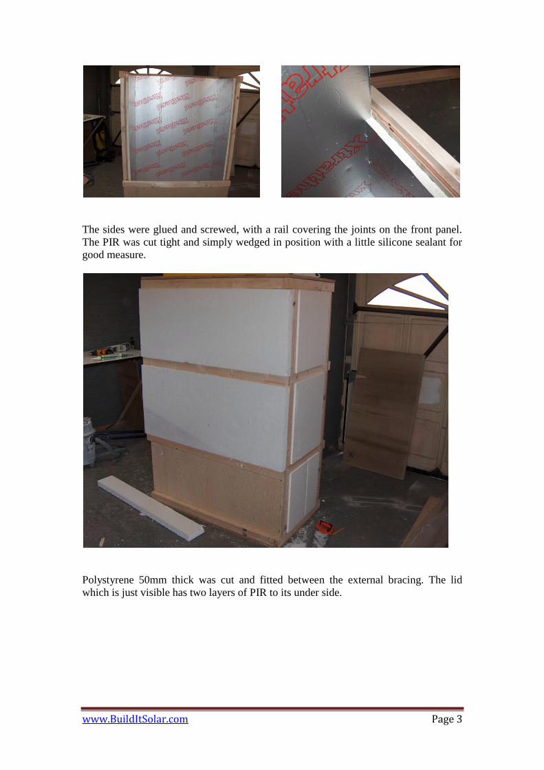
The sides were glued and screwed, with a rail covering the joints on the front panel.
The PIR was cut tight and simply wedged in position with a little silicone sealant for
good measure.
Polystyrene 50mm thick was cut and fitted between the external bracing. The lid
which is just visible has two layers of PIR to its under side.

www.BuildItSolar.com Page 4
The picture shows the front of the tank, with the two upper pieces of the front
missing. A second layer of polystyrene covers the sides and lid. The PIR on the
inside of the lid has enough space around its sides to allow for the fiberglass.
Fiberglass tank lining
www.BuildItSolar.com Page 5
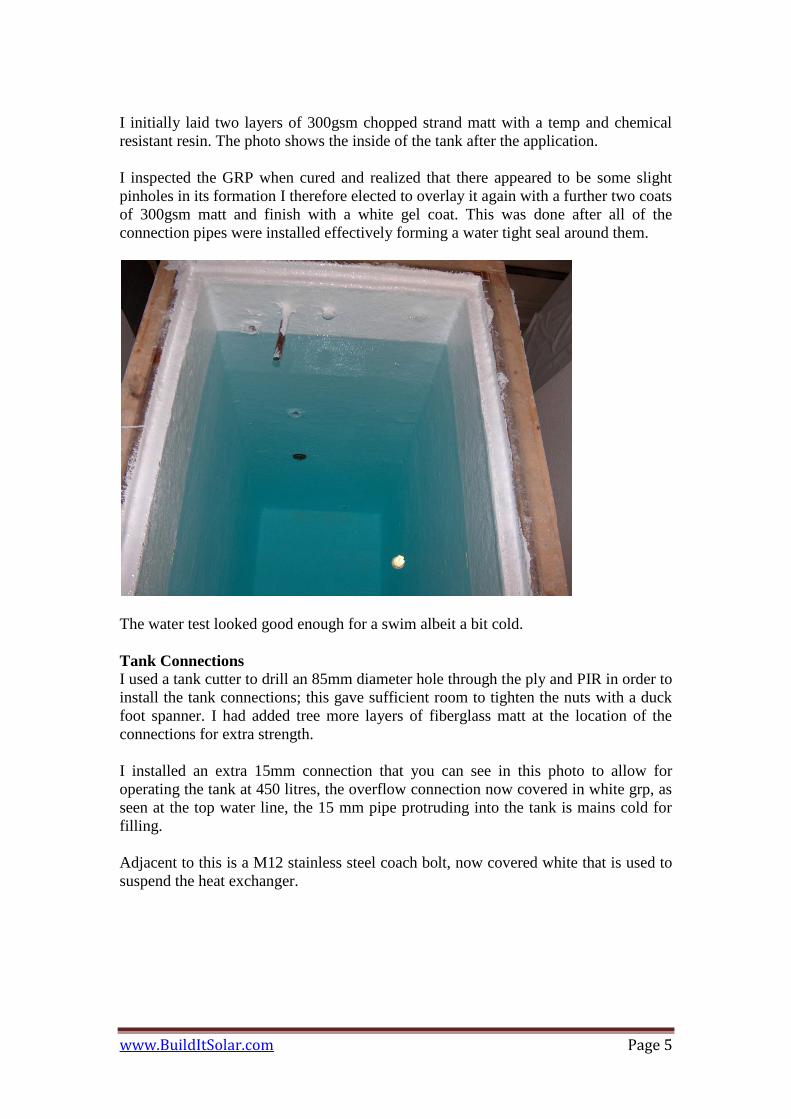
I initially laid two layers of 300gsm chopped strand matt with a temp and chemical
resistant resin. The photo shows the inside of the tank after the application.
I inspected the GRP when cured and realized that there appeared to be some slight
pinholes in its formation I therefore elected to overlay it again with a further two coats
of 300gsm matt and finish with a white gel coat. This was done after all of the
connection pipes were installed effectively forming a water tight seal around them.
The water test looked good enough for a swim albeit a bit cold.
Tank Connections
I used a tank cutter to drill an 85mm diameter hole through the ply and PIR in order to
install the tank connections; this gave sufficient room to tighten the nuts with a duck
foot spanner. I had added tree more layers of fiberglass matt at the location of the
connections for extra strength.
I installed an extra 15mm connection that you can see in this photo to allow for
operating the tank at 450 litres, the overflow connection now covered in white grp, as
seen at the top water line, the 15 mm pipe protruding into the tank is mains cold for
filling.
Adjacent to this is a M12 stainless steel coach bolt, now covered white that is used to
suspend the heat exchanger.

www.BuildItSolar.com Page 6
The tank connections provide a 22mm outlet to the pumps, approx 100mm up from
the base. This also serves as a drain off for emptying the tank. I have installed two
more 15mm connections, to top most being the vent and overflow which sets the
maximum water level at 850 litres, a third connection allows me to drain and operate
the tank at 600 litres.

www.BuildItSolar.com Page 7
The photo is of the narrow end of the tank, showing the two central heating pumps
and wiring box.
The 15mm vertical pipe emanates from the overflow connection and connects to the
pump inlet pipe at the bottom of the tank, a ball valve allows for draining the tank.
The two 22mm connections that are shown enable the tank to be drained as described
above.
The pipe / cylinder stat that is shown will be coupled to the pump inlet pipe when
finished and will govern the maximum tank temp (around 70 °C)
Two pumps
The solar collectors will be roof mounted, and the tank will at ground level at the side
of the house, this gives a static head of around 8m from tank to top of collector, the
domestic circulating pumps are designed for a 6m head therefore I have places two in
line to give sufficient flow through the collectors.
It is important to mount these types of pumps vertically and below the normal water
level of the tank, this prevents cavitations (air bubble forming in the pumps)
Sealing the lid
The lid pictured below is constructed from the 18mm ply with two layers of 25mm
PIR that are stepped to fit on and inside the tank. I noticed from Gary’s system that he
had some difficulty forming an air tight seal to his tank, my solution was to use two
thick beads of silicone applied directly to the lid. I covered the lid with mold release
wax to prevent the silicone from adhering to it. I simply fitted the lid to the tank and
screwed it down, thereby compressing the silicone between the lid and the tank.
I left this undisturbed for 2 weeks for the silicone to cure. It takes a while when not
exposed to the atmosphere. I had some difficulty removing the lid initially and had to
resort to a crow bar, but once the initial seal with the wax had broken, the lid and
sealing methods works perfectly with the silicone fully adhered to the tank but not the
lid.

www.BuildItSolar.com Page 8
The heat exchanger (HE)
I followed the same principals as the other 1k systems by using a simple pipe
immersed in the tank as a heat exchanger. I looked around for suitable PEX pipe in
22mm diameter but I could only find 25m coils that were relatively expensive. So I
chose to use 22mm hard copper pipe in 3m lengths as a shorter overall length would
be possible given its thermal conductivity in comparison to the PEX.
I produced a simple spreadsheet in an attempt to calculate the length of the heat
exchanger based upon a simple power translation resulting in a 63m long pipe. This
should provide sufficient surface area to lift the incoming water temp to the max tank
temp without any reduction in the normal flow rates.
The HE is to be suspended in the tank, on two nylon ropes from the two coach bolts,
thereby allowing me to alter its position in relation to the water levels. My intention
was to be able to increase or decrease to volume in the thermal store in relation to the
seasons and the available solar gain, hence the additional tank connections I made.
To reduce friction losses in the HE, I chose to form all of the bends in stead of using
elbows with unions to join the tubes together. I produced a sample radius pipe to
determine the start positions of the bends, this helped tremendously in positioning the
pipes in the bender.
The white tape marks the start point of the bends.
The HE is designed as a single pass with the cold entering the bottom, the hot exiting
the top and was designed to be an irregular pattern with the intention of dissipating the
coils as much as possible in the area that I had.

www.BuildItSolar.com Page 9
The vertical pipe in the forefront is the cold inlet to the HE. The pipe in the
background is only as a support and is not connected hydraulically to the HE.
www.BuildItSolar.com Page 10
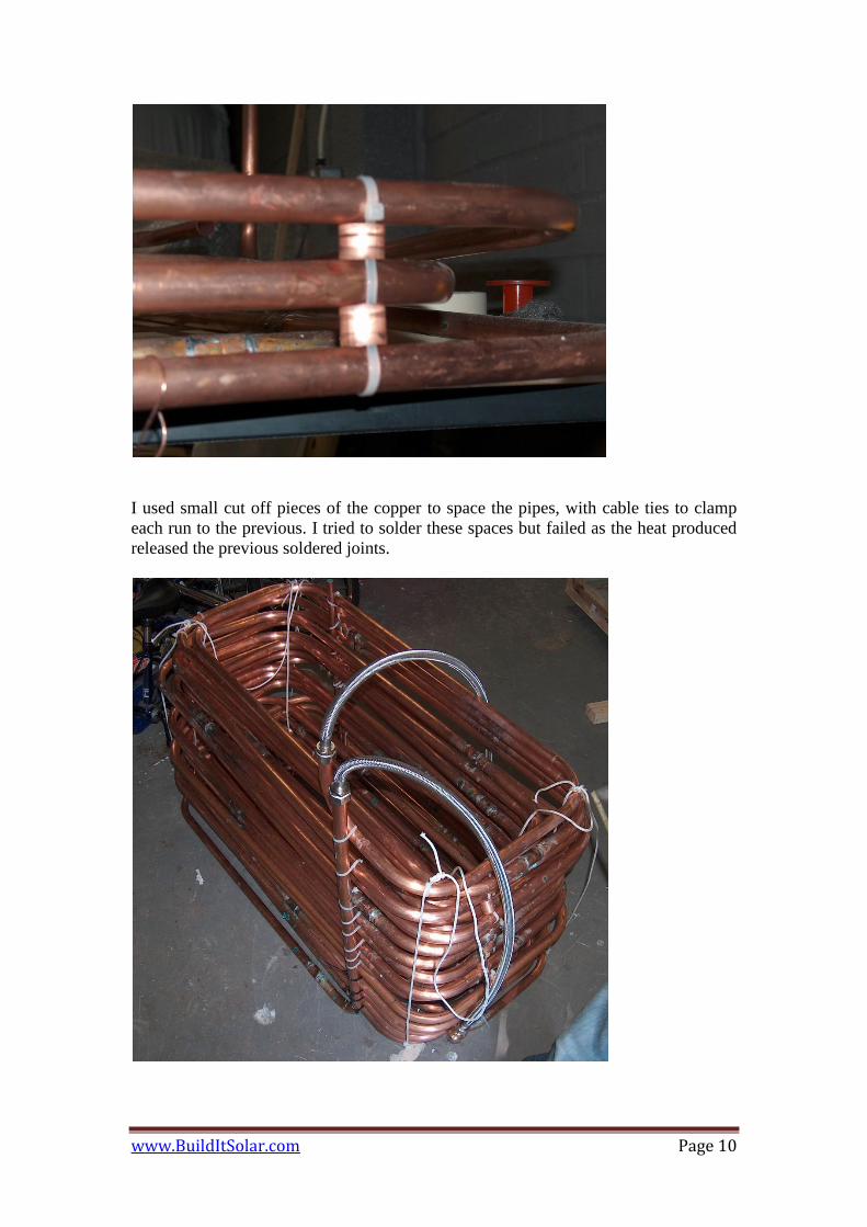
I used small cut off pieces of the copper to space the pipes, with cable ties to clamp
each run to the previous. I tried to solder these spaces but failed as the heat produced
released the previous soldered joints.

www.BuildItSolar.com Page 11
The finished HE, I have used flexible connectors 500mm long to join it to the tank
connections, the nylon ropes are visible that will suspend this inside the tank, I had
simply tied a couple knots in the rope at the desired positions.
Make sure you pressure the exchanger before fitting, I am experienced at soldering
and had no leaks except for one union that I had completely negated to solder.
Pressure testing this prior to fitting in the tank is wise. One thing to note is this weight
of this HE, there is a lot of copper here and it is fairly heavy.
Taken before finishing the white GRP
I did a dry run of this installation to set the positions of the knots in the suspension
ropes, for this I had the tank on its side so as to take the weight of HE off the ropes,
the photo also shows the two flexible pipes connected between the HE and the inlet /
outlets cast into the tank.

www.BuildItSolar.com Page 12
Taken before finishing the white GRP
The pipe on the right is the flow return from the solar collectors, the middle pipe is the
cold feed for filling the tank, the overflow / vent connection on the left.

www.BuildItSolar.com Page 13
Sighting the tank
The has to live outside, the intention is to enlarge the shed to house the tank in the
future , but I have plenty of plastic sheeting available (for free) so I opted to build an
temporary enclosure.
The base was produced form the spare ply (same cross sectional size of the tank) and
insulated between the support timbers (photo shows it upside down)
A MDF sheet was used to cover the whole of this forming the bottom, this was
fibreglassed over to make a water proof base, the sides were made from the plastic
mounted on a simple frame, this overlapped the sides of the base by around 50mm to
prevent water ingress.

www.BuildItSolar.com Page 14
The tank is designed to fit centrally in the enclosure, with the space being filled with
polystyrene and rockwall bats.
I constructed a simple ‘door’ in the end panel that covers the pumps for ease of
access, using two 30mm plastic angles down each side to prevent water ingress. The
door simply screws in place with SS screws.
Moving the tank into the enclosure was difficult due to its weight.
www.BuildItSolar.com Page 15
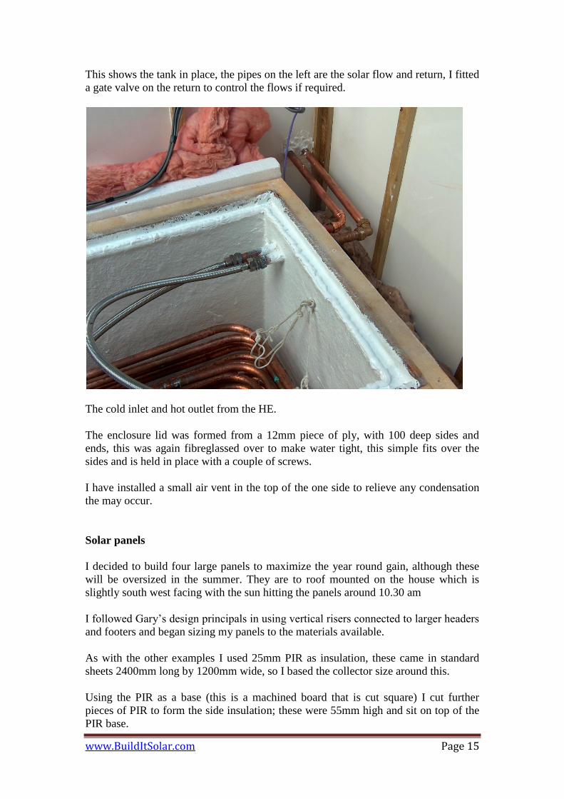
This shows the tank in place, the pipes on the left are the solar flow and return, I fitted
a gate valve on the return to control the flows if required.
The cold inlet and hot outlet from the HE.
The enclosure lid was formed from a 12mm piece of ply, with 100 deep sides and
ends, this was again fibreglassed over to make water tight, this simple fits over the
sides and is held in place with a couple of screws.
I have installed a small air vent in the top of the one side to relieve any condensation
the may occur.
Solar panels
I decided to build four large panels to maximize the year round gain, although these
will be oversized in the summer. They are to roof mounted on the house which is
slightly south west facing with the sun hitting the panels around 10.30 am
I followed Gary’s design principals in using vertical risers connected to larger headers
and footers and began sizing my panels to the materials available.
As with the other examples I used 25mm PIR as insulation, these came in standard
sheets 2400mm long by 1200mm wide, so I based the collector size around this.
Using the PIR as a base (this is a machined board that is cut square) I cut further
pieces of PIR to form the side insulation; these were 55mm high and sit on top of the
PIR base.

www.BuildItSolar.com Page 16
The collector sides are formed with 6mm WBP ply wood, 90mm high, a 20 x 45 mm
timber support was placed in each corner to screw the ply together, this was notched
out of the base PIR. The ply protrudes past the PIR side insulation by 10mm, such that
the polycarbonate glazing sits inside the ply frame and rests on top of the PIR side
insulation.

www.BuildItSolar.com Page 17
The pipe grid was made from 15mm hard copper risers, connected by T pieces to
22mm headers and footers in the same manner as the other panel builders.
In England we do not use aluminum for soffit material, and finding any type of
aluminum in this shape or form was impossible therefore I elected to use a solid
aluminum sheet for the absorber. This came as a 2500mm by 1250mm by 1mm thick
sheet.
I bent the sides and ends up to the internal dimensions on the PIR side, using a knife
to score the sheet enables easy bending.
www.BuildItSolar.com Page 18
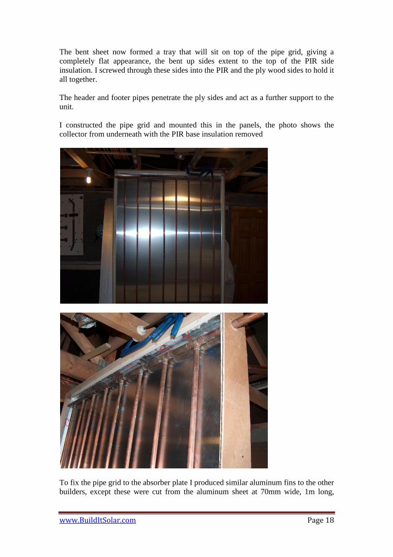
The bent sheet now formed a tray that will sit on top of the pipe grid, giving a
completely flat appearance, the bent up sides extent to the top of the PIR side
insulation. I screwed through these sides into the PIR and the ply wood sides to hold it
all together.
The header and footer pipes penetrate the ply sides and act as a further support to the
unit.
I constructed the pipe grid and mounted this in the panels, the photo shows the
collector from underneath with the PIR base insulation removed
To fix the pipe grid to the absorber plate I produced similar aluminum fins to the other
builders, except these were cut from the aluminum sheet at 70mm wide, 1m long,
www.BuildItSolar.com Page 19
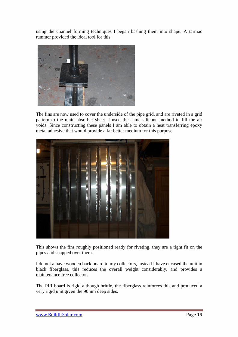
using the channel forming techniques I began bashing them into shape. A tarmac
rammer provided the ideal tool for this.
The fins are now used to cover the underside of the pipe grid, and are riveted in a grid
pattern to the main absorber sheet. I used the same silicone method to fill the air
voids. Since constructing these panels I am able to obtain a heat transferring epoxy
metal adhesive that would provide a far better medium for this purpose.
This shows the fins roughly positioned ready for riveting, they are a tight fit on the
pipes and snapped over them.
I do not a have wooden back board to my collectors, instead I have encased the unit in
black fiberglass, this reduces the overall weight considerably, and provides a
maintenance free collector.
The PIR board is rigid although brittle, the fiberglass reinforces this and produced a
very rigid unit given the 90mm deep sides.

www.BuildItSolar.com Page 20
This shows the corner view of the collector (upside down) ready for fiber glassing, the
black tape was a temporary measure to hold the base PIR in position while moving.
The collector underneath (again upside down) has been covered in fiberglass, its white
spotted appearance is due to it being sanded smooth ready to take a top coat of resin.
Unfortunately the camera broke after this point, so I could not photo the finished
collector.
I used 10mm twin wall polycarbonate sheeting to glaze the units, this simply sat
inside the ply frame and rested on the PIR sides, standard glazing silicone was used to
seal it down with a 15mm aluminum angle fitted around its perimeter.
Because the angle I had was relatively narrow I was concerned that the glazing sheet
may lift and become detached in strong winds, so to be sure I fitted an aluminum strap
30mm wide across the middle of each collector.
www.BuildItSolar.com Page 21
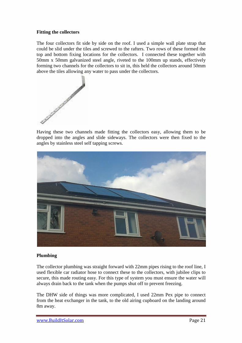
Fitting the collectors
The four collectors fit side by side on the roof. I used a simple wall plate strap that
could be slid under the tiles and screwed to the rafters. Two rows of these formed the
top and bottom fixing locations for the collectors. I connected these together with
50mm x 50mm galvanized steel angle, riveted to the 100mm up stands, effectively
forming two channels for the collectors to sit in, this held the collectors around 50mm
above the tiles allowing any water to pass under the collectors.
Having these two channels made fitting the collectors easy, allowing them to be
dropped into the angles and slide sideways. The collectors were then fixed to the
angles by stainless steel self tapping screws.
Plumbing
The collector plumbing was straight forward with 22mm pipes rising to the roof line, I
used flexible car radiator hose to connect these to the collectors, with jubilee clips to
secure, this made routing easy. For this type of system you must ensure the water will
always drain back to the tank when the pumps shut off to prevent freezing.
The DHW side of things was more complicated, I used 22mm Pex pipe to connect
from the heat exchanger in the tank, to the old airing cupboard on the landing around
8m away.

www.BuildItSolar.com Page 22
The airing cupboard housed the old hot water cylinder from the old boiler system so
all of the connections into the plumbing system were there although not in the
orientation I would have preferred.
The state of the art combi boiler I have installed (Worcester Bosch) is not designed to
take pre heated water above 25 °C although it is self modulating, so to overcome this I
have installed a split system using a 3 port valve. Using a thermostat on the heat
exchanger out flow to control the 3 port valve the DWH is either routed directly to the
taps or through a thermostatic valve to the boiler.
The thermostat valve blends the water to around 35 °C, for which I have reduced the
boiler outflow temperature according and all works fine.
I have also installed a second thermostatic valve on the direct flow to the taps to
prevent scalding.

www.BuildItSolar.com Page 23
I had previously installed a pressure reducing valve on the mains supply, this has
effectively created a sealed system when the taps are not open, for this reason I have
included a potable expansion tank and 6 bar pressure relief valve of the hot water
connection from the heat exchanger to account for any expansion that may occur as
the tank heats.
The photo shows the connections as follows from the left hand side:
Pressure relief valve with overflow pipe
Expansion tank
22mm return from the heat exchanger that connect to the 3 port valve (grey)
The 15mm pipe is the cold feed (next to red gate valve) that feed the heat
exchanger in the tank and also the cold side of the thermostatic valves. This
includes two full flow ball valves to isolate if necessary
Thermostat valve (left of 3 port) takes cold feed from above and passes into
the DHW system through a non return valve and the red gate valve.
The thermostatic valve (right of 3port) again takes cold from above and passes
pre heated water into the white pex pipe that connects to the boiler.
The 15mm pipe is the cold feed (next to red gate valve) that feed the heat
exchanger in the tank and also the cold side of the thermostatic valves. This
includes two full flow ball valves to isolate if necessary
Controls
To control the system I found a simple differential temperature controller that works
off 12v dc (£25), I made a control panel that incorporates 5 temperatures displays. I
found these on a pc modding web site for around £3.50 each. The cables can be
extended without affecting the readings
www.BuildItSolar.com Page 24
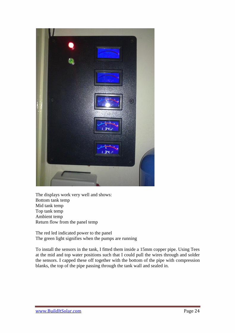
The displays work very well and shows:
Bottom tank temp
Mid tank temp
Top tank temp
Ambient temp
Return flow from the panel temp
The red led indicated power to the panel
The green light signifies when the pumps are running
To install the sensors in the tank, I fitted them inside a 15mm copper pipe. Using Tees
at the mid and top water positions such that I could pull the wires through and solder
the sensors. I capped these off together with the bottom of the pipe with compression
blanks, the top of the pipe passing through the tank wall and sealed in.

www.BuildItSolar.com Page 25
Costs
In terms of costs I have spent around £1700 (sterling), this is obviously more than the
1K target, but mainly due to my choice of materials which included the GRP
laminates, copper pipe work and the addition plumbing items that I fitted (expansion
tank, pressure relief, 3 port valve and the thermostatic controls) and the additional size
and number of collectors.
We had the first quarterly gas bill (feb to may) which was around £100 lower than the
previous year even though we have hade the coldest winter since god was a boy.
Conclusions
I installed the system in mid February and had it running for 3 months, I have only
just purchased a data logger so will post the data as time goes on.
One thing I had noticed with the temp displays was that having the diff sensor at the
bottom of the tank, as the sun sets in the evening and less power is available in the
panels the resulting water temperature existing the panels was lower than the
temperature at the top of the tank, and was effectively cooling the tank. Moving the
diff sensor to the top of the tank cured this.
If I were to build this again I would make the tank more square and place all of the
insulation on the inside. This would reduce the overall losses and make it easier for
fiberglass.

www.BuildItSolar.com Page 26
The collector sides that I made from 6mm ply was a little flimsy until the fiberglass
had cured, whilst this has no effect on the finished product it was difficult to keep
these perfectly straight beforehand, I would suggest using 12mm instead.