m/xfitin comfamy - defense technical information · pdf file · 2013-04-23m/xfitin...
TRANSCRIPT

■ v\\:';':^':.\.
mu
RESEARCH mOGRAK ON APPLICATION OF JET COMfflESSOR TO KAGNETOPLAFMADlfNAMIC
ELECTRICAL POWER GENERATION
Final Report
1 June 1963 - 30 November 1961
KND - 3176
M/XFITIN COMfAMY NUCLEI R DIVISION

REÜEilRGH FROGSAK ON APH,ICATI(»I OF JET COMPRESSOR TO KAGNETOPUSMADmMI C
ELECTRICAL PÖWiR CENSIATION
Final Report
1 June 1963 - 30 November 1961*
KI© - 3176
i
RSSEARGH FROCÄAM QN APPLICATION OF JET COMPRESSCR TO HAGNETOFIASHADYNAMIC ELECTRI1AL PCWiR GENERATION
Final Report
1 June 1963 - 30 November I96I4
MND-3176
Order Number: 327 Project Code Numbers 2980 Date of Contract: 1 June 1963 Contract Number: Nonr-li087(00) Contract I 'iration Date: 30 November 196ii
Project Scientist: Hr. Cheng Shih, Hione 687-3800 Ext. 9315, Area Code 301
Contractor: Martin Marietta Corporation Baltimore, Maryland 21203
Approved by:
W./J. Levedahl, Manager Research
Nuclear Division
Martin Marietta Corporation Baltimore 3» Maryland
December 196l
Reproductiwi in whole or in part is permitted for any purpose of the United States Government.

r* Foreword
This report presents the work accomplished under contract Nonr-ii087(00)
for the period 1 June 1963 through 30 November 1961*. The program was carried
out under the auspices of the Advanced Research Project Agency and the Power
Branch of the Office of Naval Research and was sponsored by Dr. J. Huth of
I ARPA and Mr. J. A, Satkowski of ONR.
1
c r L
Acknowledgement
The components in the experimental loop were desired by J. Goeller.
Sxperiaentation was carried out by E. K. Zavodny with assistance fro»
W. Calary. W. lyon worked out the equations for correlating experimental
results to ideal wies and also the OH computer code for such purpose.

ii
TABLE OF CONTENTS
Forew rd
Table of Contents
I, Introduction and Suraraary
II. Analytical Studies
III. Experimental Procedures
IV. Results, Analysis and Discussion
V. Figures
71. Appendix
C. Shih
£, Zavodny
C. Shih
W, Lyon
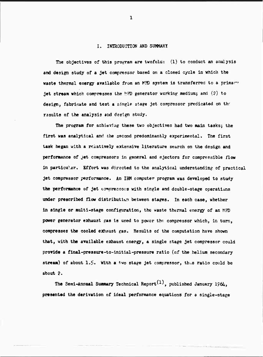
I. INTRODUOTION AND SUMMARY
The objectives of this program are twofold: (1) to conduct an snalysis
end design study of a jet coatpressor based on a closed cycle in which the
waste thenual energy arailable from an MPD system is transferred to a primär-"
jet stream which compresses the V.'PD generator working mediuraj and (?) to
design, fabricate and test a single stage jet compressor predicated on thr
r3sult8 of the analysis and design study.
The program for achievlag these two objectives had two main tasksj the
first was analytical and the second predominantly experimental. The first
task began with a relatively extensive literature search on the design and
performance of jet compressors in general and ejectors for compressible flow
In particuXar. Effort was directed to the analytical understanding of practical
jet compressor performance. An IBM computer program was developed to study
the performance of jet c^wjoressors with single and double-stage operatiuns
under prescribed flow distribution between stages. In each case, whether
In single or multi-stage configuration, the waste thermal energy of an JiFD
power generator exhaust pas is used to power the compressor which, in turn,
compresses the cooled exhaust gas. Results of the computation have shown
that, with the available exhaust energy, a single stage jet compressor could
provide a final-pressure-to-initial-pressure ratio (cf the helium secondary
stream) of about 1*5* With a t.vo stage jet compressor, th^s ratio could be
about 2,
The Semi-Annttal Summary Technical Report'1^, published January 156^,
presented the derivation of ideal performance equations for a single-stage

I 1
jet compressor of the constant-ares, mixing-chamber type, as well as
modified equations which take into consideration the various efficiency
öotffielente. Also presented were the analysis and design of the various
components of the experimental loop shown in Figure 1, as well as the
engineering drawings. Except for direct reference purposes, this work
will not be covered In this report,
Tn the second task, a closed loop test setup was designed, fabricated
and installed. The test setup consists of s gaseous loop and s condensing-
vapor loop. The gaseous loop contains helium saturated with cesium vapor
and forms the secondary stream, simulating the working medium of an KPD
power generator» In the condensing-vapor loop, pure cesium is vaporized,
superheated and discharged under high pressure through a convergent-
divergent nozzle to font the primary stream of the jet compressor. After
mixing of the two streams and diffusion to low velocity, the cesium Is then
condensed, seoarated from the gas and pumped back to the boiler to repeat
the cycle.
Fabrication and Installation of the loop was completed by the end of
September I96h. Leak checking and outgassing were completed by the first
week of November 196U, During outgassing, the boiler wall was very gradually
heated to 1300 K. Measurements of heat dissipation at various wall tempera-
tures were taken to provide data for heater efficiency calculations. The
heater efficiency thus calculated was about 90%.
A functional check of the components was made on 3 November 196^,
Every component functioned smoothly. The first series of experimental
runs were started on November 6, 19th and the results obtained from that
■::.
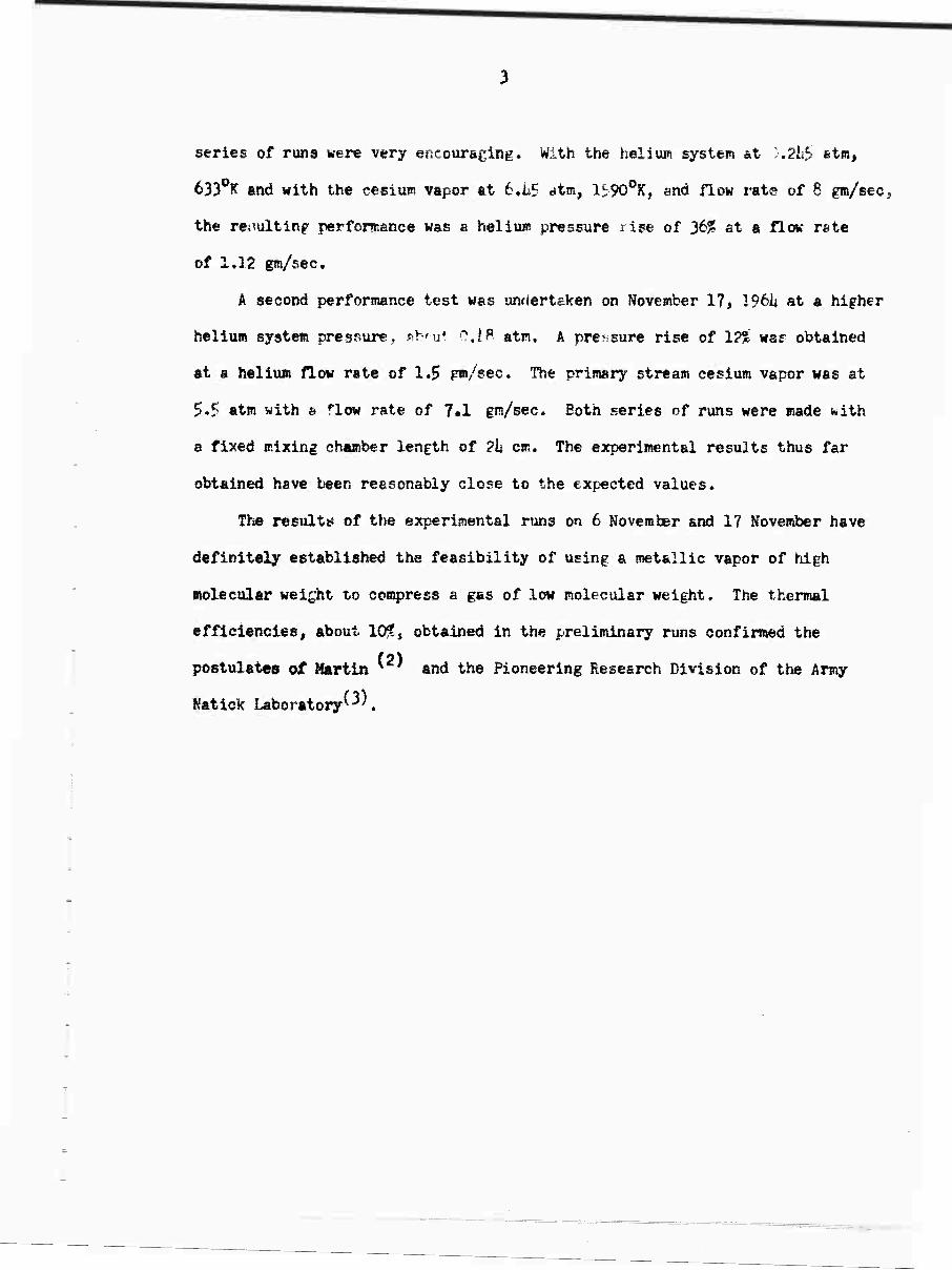
series of runs were very encouraeing. With the helium system at '.216 stm,
6330K end with the ceiium vapor at 6.LS atm, 15;90oK, and flow rats of 8 gm/sec,
the rer.ulting performance was a helium pressure rise of 3^* 6t a fie« rate
of 1,12 gm/sec.
A second performance test was unriertaken on November 17, I96I4 at a higher
helium system pressure, sfcnul O.lB atm, A pressure rise of 1?% waf obtained
at a helium flow rate of 1.5 gm/sec. The primary stream cesium vapor was at
5.? atm with a flow rate of ?•! gm/sec. Both series of runs were made with
a fixed mixing chamber length of ?\i cm. The experimental results thus far
obtained have been reasonably close to the expected values.
The results of the experimental runs on 6 November and 17 November have
definitely established the feasibility of using a metallic vapor of high
molecular weight to compress a gas of low molecular weight. The thermal
efficiencies, about 10!?, obtained in the preliminary runs confirmed the
postulates of Martin * ' and the Pioneering Research Division of the Army
Natick Laboratory'-^.
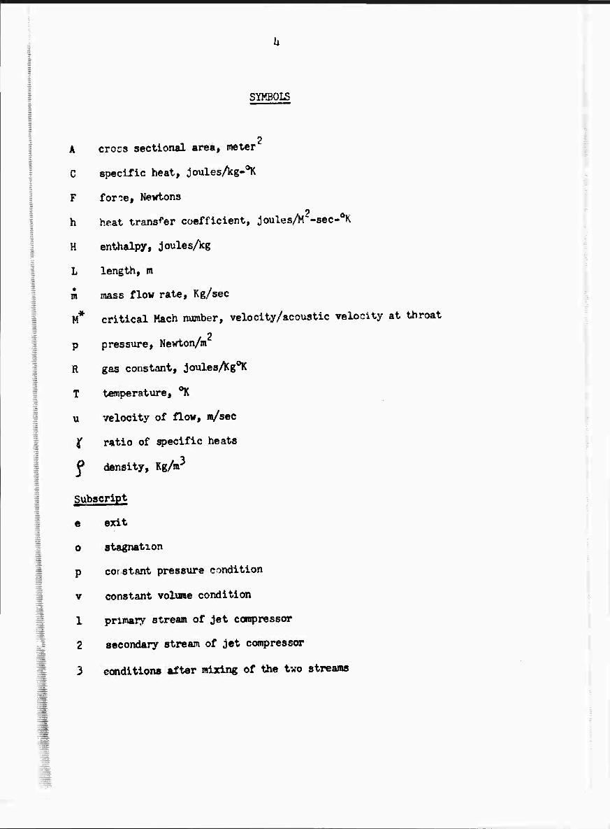
SYMBOLS
2 A cross sectional area, meter
C specific heat, joulesAg-0^
F for'ie, Newtons
h heat transfer coefficient, ;Joules/M"-8ec-0K
H enthalpy, joulesAg
L length, m
m mass flow rate. Kg/sec
M* critical Mach number, velocity/acoustic velocity at throat
p pressure, Newton/m
R gas constant, joulesAg0^
T t«nperat\ire, ^K
u velocity of flow, «/sec
jf ratio of specific heats
f dtensity. Kg/«3
Subscript
e exit
0 stagnation
p corstant pressure condition
v constant volxaae condition
1 primary stream of jet coropressor
2 secondary stream of jet compressor
3 condition« after mixing of the two streams

I
II. AnftlytiCcJ Study
An IHK 709ii digital computer program, based on the ideal performance
equations origindily developed at the Research Lab, wss made for the para-
metric study of performance of jet compressors with one stage and two stsges,
respectively. In each case the energy required to power the compressor is
derived from the waste heat energy in the exhaust from a model KH) power gen-
erator. The characteristic parameters of the generator are as follows:
Generator geometry: constant cross-sectional area
Working medium, mol fraction .9? He + ,01 Cs
Stagnation temperature ?0600K
Mach number at generator inlet 0,y5
Electrical loading factor K/U0J0 0.8
Mach No. at generator exit 1.0
Area ratio of diffuser after generator 2.8
Pressure at generator inlet 0.5 atm
Pressure drop in system outside generator 0,2$ atm
Exhaust temperature 1856°'''
The jet compressor used to circulete the MH) generator working medium
will use cesium vapor as the driving stream. It is assumed that the cesium
which forms the prlaary stream of the jet compressor is heated up from con-
densate temperature to the saturation temperature, is vapori?ed, and is
sup€rheavx?d in a heat exchanger by the exhaust heat from the KFD generator.
The temperature drop across the heat exchanger wall is assumed to be ?$0fC.
A set of modified enuations, taking into consideration the effects of
non-idesl discharge coefficients, mixing efficiency, etc. was prograimned
as a basis for evaluating the experimental results. These computer programs
were reported in the Semi-Annual Technical Report KND-312i4 January I96I4.
Results of computer runs indicated a possible pressure rise of hT%
vith single stage areration and a pressure rise of 91% with two stage
operation using available exhaust heat from an assumed MFD generator.
Both cases represent ideal co'litions. The magnitude of the program did
not permit computer calculations of three stage operation.

III. EXPERIMMTAL PROGfDUR^
1, Experiaental Setup
An experiaental single stage jet coapressor was designed, fabricated
and operated♦ Superheated cesium vapor is discharged under high pressure
through a converpnt-divergent nozzle to form the primary stream. The
second.'i*7 strfcam is composed of helium containing a small amount of cesium
vapor to simulate the working medium of ar MFD power generator. The com-
pressed mixture is cooled in a condensor ffter passing through a diffuser,
permitting separation and re-cycHng of the cesium and helium. The various
components of the system have been described in the first Semi-Annual Report,
MHD-312b* A block diagram of the jet compressor system and instrumentation
is shown in Figure 1,
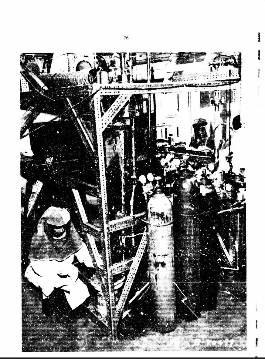
Pictures of a number of the important components of the loop are included
in this report. Figure 2 shows the boiler-superheater unit in the welding
fixture. The boiler is made of Nb-1$ Zr alloy» It consists of two vertical
concentric cylindrical shells. The cesium to be boiled is contained between
the two cylindrical walls. Heat is supplied by means of radiation from an
electrical resistance heater located inside of the inner boiler shell. The
boiler heater. Figure k, is made of Nb-ll Zr alloy tubing with knurled sur-
faces to increase surface «wissivity« Similarly, the inner surface of the
inner boiler shell was knurled for better radiation absorption. i-
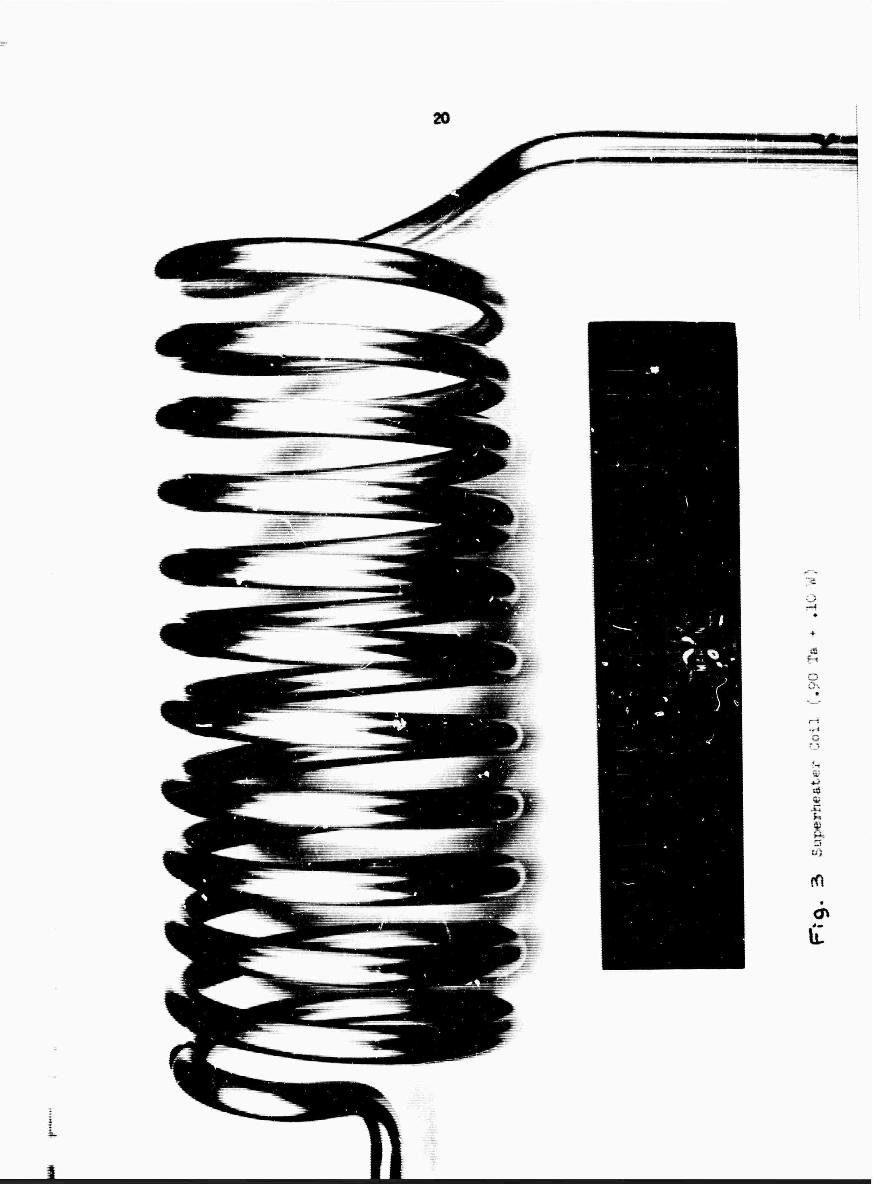
The superheater, having a temperature range from ll00oK to ie00oK, is
r made of Ta-lOf W alloy tubing and serves both as a vapor container and an
electrical resistance heater itself. The superheater is in the form of a
i-«

8
coll to reduce the heat logs. Figure 3 shows the superheater coil before
it was welded onto the boiler doae, Sorae difficulties were encountered in
procuring this coil. The original vendor made three unsuccessful tries to
electron-beaffl weld sheet stock and then draw it to size. The job was then
turned over to National Research Gorporation who used an extrusion process.
An extrudable ring was first made from the ingot. The ring was then extruded
and drawn to size by the Superior Tubing Company.
No information about coiling tubing of this slloy teas available. It was
finally coiled at the Ztnk Pipe Bending Company of Harrisburg, Pennsylvania
under close supervision of Martin personnel. The coiling was done at room
temperature since it appeared that no advantage would be obtained by heating
to any temperature below that at which damaging oxidation might occur. Being
previously annealed at 17000K, the material was In a cold-workable condition
with a hardness of Rockwell B-91. With a reruired coil IB of 3-1/8 inches,
the mandrel was sized at 3 inc»es to compensate for the 1/16 inch radial
spring-back.
Three compressor fixing chamber and diffuser sections were made for
this experimental single stage unit, covering a range of mixing chamber
lengths from hn to l?". One section has a fixed mixing chember length
of li inches. The second (me, having a variable mixing chamber length
of $ to 7-1/2 inches, is shown in Figure 5. The section presently installed
has a length range of 6-1/? to 12 inches. Experiments conducted to date
have been with a length of 9-3/8 inches.
2. Instrumentation ^i i i ii i . M —MI ■ r»»=M^t
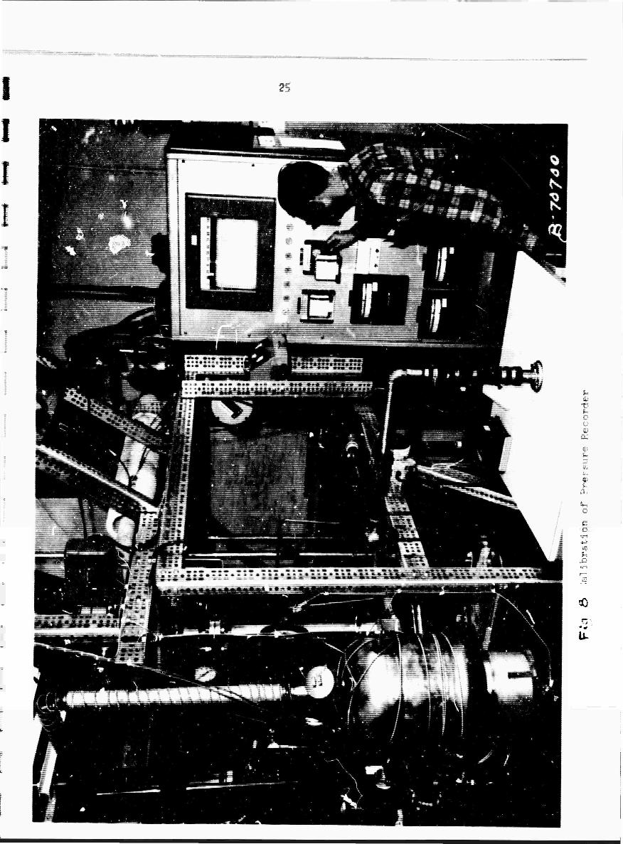
The essential instrumentation consists of pressure and temperature
sensors at strategic points in the loop and a differential pressure, ori-

fice type flow laeter for helium flow-rate meesurements. Tne holiua
static pressures at the notale (P^ and P^), the mixing chaaber static
pressure (Pi), the diffuser exit static pressure (P^) and the helium
How differential pressure are detected by pneumatic transducers and
continuously recorded on strip-chart recorders. The helium plenum,
cesium pump outlet and superheater pressures are indicated by Bourdon
gauges.
Temperatures raeasurad using thermocouples are recorded on a multipoint
recorder. Important temperatures measured include the boiler heater and wall
tsmperstures (Tng and T^), the cesium vapor temperature (T^)» the helium
tenperature at the nozsie (T-), the mixing chamber temperature (T^), and
the plenuR tenqperature (T,). Thermocouples on the helium preheater and
cesium preheater are used as input signals to controllers which maintain
pre-set temperatures.
For temperature mepsurewents below 10OO"K in cesium atmosphere, chromel-
aluael thermocouples in 316-SS sheaths are used. For temperatures above
1000°*, W-^ Re vs \i'2(0 Re thermocouples are used. Bare thermocouples
were preferred wherever possible and a dual installatj.on was used for
reliability. This proved fortunate, since the W-31 Ra wire in one of the
two bare thermocouples originally welded onto the bi.viler heater elements
broke off when the heater was assembled« Since dir^ssembly and reassembly
are both risky and tiae consuming, the decision wa? made to rperate with
one thermocouple! it has been functioning nicely to date. With the data
obtained during the outgassing period and during the experimental runs,
even this thermocouple is no Ioniser needed* P4. vs Pt-Rh thermocouples
were not used for the intermediate temperature range since our experience
Indicated that this reacts with tantalum and columbium at that temperature
i
f
i

10
range when the materials are fused tcfether. However, one Pt vs Pt-Rh
couple is lightly spot welded to the boiler outer wall which is btlow
UooV
3. Loop Purification and Cesiua Loading
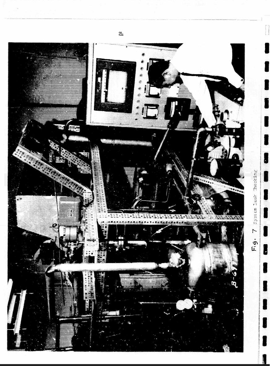
All components of the loop were individually leak checked with a Bass
spectrometer leak detector. After assembly, the entire loop was thoroughly
leak checked to insure leak tightness. It was then evacuated with a dif-
fusion pump and all components of the loop were heated to their operating
temperature or higher, with the exception of the superheater coil. Following
this outgassing procedure, the loop was filled with helium to approximately
one atmosphere of pressure and the helium was slowly circulated with the
cesium pump. The impurity level was monitored with a gar Chromatograph
while the loop was again hested. No impurity buildup was detected.
Initially a 10 pound charge of cesium was loaded into the loop. It was
first purified by heating to li000C for ?h hours while in contact with a
titanium sponge getter. This initial charge proved to be inadequate to
operate the loop, and an additional 10 pound charge was loaded in 5 pound
batches after purification in the same manner.
h» Experimentation
Two sets of runs have been made with the jet compressor loop., the
first on 6 November 1961 and the second on 17 November 1961*. The primary
objective of these runs was to prove the principle of jet compressor
operation with an alkali metal vapor as the driving fluid. A secondary
objective was to obtain preliminary data for performance and efficiency
analysis. Operation of the loop was satisfactory and both objectives wer«
met.

i =
L
n
During the first set of runs (Run A), the cesium boiler temperature
(Tg) was brought up to 10600!C with a helium pressure of 0.50 at» abs, then
Increased to 11650K (16U00T ~ 72 psia) with a helium pressure of 0.25 atm
abs. Data are listed in Table I. At the latter condition, the cesium
vapor temperature at the superheater exit was calculated ts 1590 K, while
the cesium flow rate was 7.1 g/sec. The resultant performence was a helium
pressure rise of 3<# at a flow rate of 1.1? g/sec.
The reported cesium vapor temperature is that calculated from a heat
balance because of inaccurate readings of the two thermocouples that had
been installed to detect this temperature. There is also some uncertainity
in the cesium flow rate, which is a function of the stroke length of the
variable-stroke diaphram type pump. The pump calibration may not be reliable.
Wie second set of runs (Run B) was carried out at a helium pressure of
one-half atmsophere. The maximum boiler temperature was llli50K. Other con-
ditions were a cesiua flow rate of 7.1 g/sec and cesium vapor temperature
of l3l80fC.

IV. ANALYSIS OF EXPLRDffiNTAL RESULTS
Data sheets for the prelininary tes^ runs conducted on 6 November
and 17 November 1961 are shown in Tables I and II. The heliu» flo» rates
and the four pressures (P^ thru P^) were recorded on strip charts. Analyses
were made on a few ateady-state runs, and the results are tabulated in Table
III. Explanations are offered for some of the items.
1. Heat Loss from the Boiler and Superheater on Data Taken During the Outgassing Period""
With no fluid circulation inside of the boiler and superheater, which
were enclosed in a vacuum chamber., the total power to the heater must have i
been dissipated to the surroundings by radiation except for a very small
fraction by conduction. During the outgassing period, the power consumption
versus boiler wall temperature from 600 K up to 13000K was recorded after an
equilibrium condition was reached. The results are presented in Figure 10
in which the solid line represents the function
Heat Loss « o< T"
For a known wall temperature, the radiation loss can be read from the curve
immediately. However, the conditions are not entir ly identical. In out-
gassing with no fluid in circulation, the boiler wall is at approximately
uniform temperature and the heater is at a temperature only slightly higher.
During experiments with circulation, the boiler wall has a temperature at
the bottom equal to or less than that of the cesium at the preheater exit
(Tj-) and a temperature equal to the saturation temperature above the liquid
level. An equivalent temperature
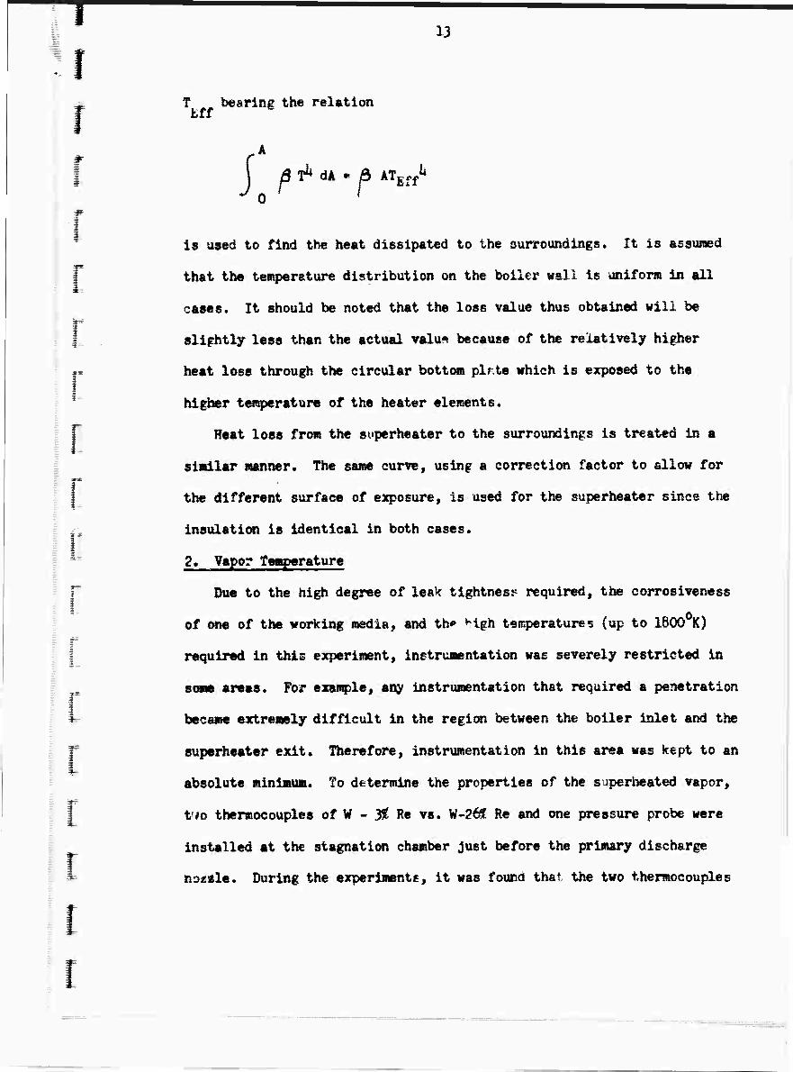
13
T bearing the relation
j ß^ dk « a | p ^ UH " rj ATEffli
0
is used to find the heat dissipated to the surroundings. It is assumed
that the temperature distribution on the boiler wall is uniform in all
cases. It should be noted that the loss value thus obtained will be
slightly less than the actual valu^ because of the relatively higher
heat loss through the circular bottom plrte which is exposed to the
higher temperature of the heater elements.
Heat loss from the superheater to the surroundings is treated in a
similar manner. The same curve, using a correction factor to allow for
the different surface of exposure, is used for the superheater since the
insulation is identical in both cases.
2. Vapor Yemperature
Due to the high degree of leak tightness required, the corrosivcness
of one of the working media, and th«» ^igh temperatures (up to 1600 K)
required in this experiment, instrumentation was severely restricted in
some areas. For example, any instrumentation that required a penetration
became extremely difficult in the region between the boiler inlet and the
superheater exit. Therefore, instrumentation in this area was kept to an
absolute minimum. To determine the properties of the superheated vapor,
Vio thermocouples of W - 2? Re vs. W-2ÖE Re and one pressure probe were
installed at the stagnation chamber Just before the primary discharge
tiottle. During the experiments, it was found that the two thermocouples

üi
read temperatures apparently much lower than the actual. Thus, the rapor
temperature is computed analytically fro« a heat balance. In this iterative
technique, a vapor temperature is fir^t assuned. The heat loss fro» the
superheater surface at this vapor temperature is estimated according to the
method descrloed in IV.1. Then a heat balance is made to check whether the
assumed vapor temperature rise is correct, and if not, another iteration is
made.
3. Cesium Flow Rate
The diaphragm pump used for cesium circulation is a metering pump with
a maoimu« capacity of 9.6 gph. When calibrated with water and alcohol, the
pump was giving reproducible results whenever the pressure cm the suction
side exceeded 7 psia. Since the system was dtsigned to operate at .23 atm
abs, a cesium head of approximately .25 atm was provided between the reservoir
and the pump suction side. However, during the experiments it was found
that the discharge rate was not equal to the calibrated rate until the system
pressure was increased to .5 atm abs. This was probably due to the unexpected
flow resistance in the passage between the reservoir and the pump. Until a
reliable flow meter is installed, it is necessary to calculate the cesium
flew rate by other means. The cesium flow rates in the data analysis were
calculated in two different ways; the results differed by a few per cent.
Knowing the boiler pressure (measured), the saturation temperature and
the heat of vaporization can be found. From the boiler wall temperatures
(measured), the heat dissipation to the ambient can be read from Figure 10
as was discussed in IV.1, Then the flow rate of cesium can oe computeo t>
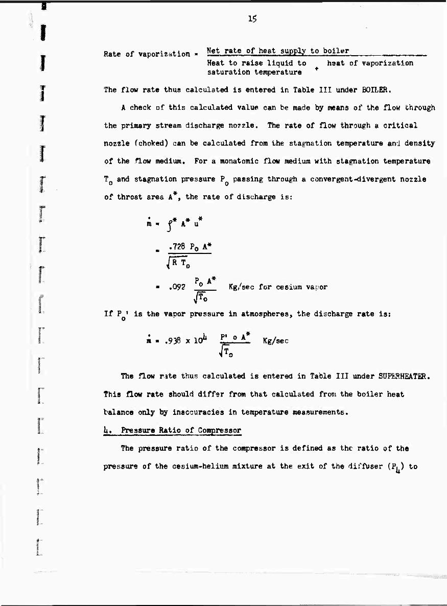
IS
Rate of vaporization - Net rate of heat supply to boiler , Heat to raise liquid to haat of vaporization saturation tenperature
The flow rate thus calculated is entered in Table III under BOILER.
A check of this calculated value can be made by means of the flow through
the primary stream discharge nozzle. The rate of flow through a critical
nozzle fchoked) can be calculated from the stagnstion temperature and density
of the flow medium. For a monatomic flow medium with stagnation temperature
T and stagnation pressure P passing through a convergent-divergent nozzle
of throat area A*, the rate of discharge is:
m - f A u
„ .728 P0 A*
/^o
P A* ■ .092 _2 Kg/sec for cesium vapor ^o
If P ♦ is the vapor pressure in atmospheres, the discharge rate is:
i t #
i a - .938 x ICT P' 0 A Kg/sec
The flow rite thus calculated is entered in Table III under SUPERHEATiR.
This flow rate should differ from that calculated from the boiler heat
balance only by inaccuracies in tenperature measurements.
L h* Pressure Ratio of Compressor
r= The pressure ratio of the compressor is defined as the ratio of the
pressure of the cesium-helium mixture at the exit of the diffuser (PL ) to
*= 1
16
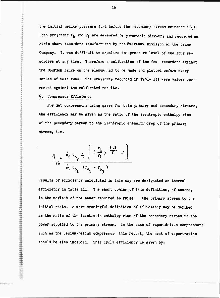
the initial helium pressure just before the secondary stream entrance (P^).
Both pressures P^ and P^^ are measured by pneumatic pick-ups and recorded on
strip chart recoi-ders manufactured by the Swartoiit Division of the Crane
Company. It was difficult to equalize the pressure level of the four re-
corders at any tine. Therefore a calibration of the fou recorders against
the Bourdon gaupe on the plenum had to be made and plotted before every
series of test runs. The pressures recorded in Table III «ere values cor-
rected against the calibrated results,
$. Compressor Efficiency
F^r jet compressors using gases for both primary and secondary streams,
the efficiency »ay be given as the ratio of the isentropic enthalpy rise
of the secondary stream to the isentropic enthalp;' drop of the primary
stream, i.e.
? "•? %. Ti
v. r-i
TU *i \ ^o, - V >
1 3
Pcsults of efficiency calculated in this way are designated as thermal
efficiency in Table III. The short coming of this definition, of course,
is the neglect of the power reouired to raise the primary stream to the
initial state. A more meaningful definition of efficiency «ay be defined
as the ratio of the isentropic enthalpy rise of the secondary stream to the
power supplied to the primary stream. In the case of vapor-dri\en compressors
such as the cesium-helium compresror this report, the heat of vaporization
should be also included. This cycls efficiency is given by:

tf 'P.
17
UY «if^^Gp-! (\-\)*
wh^re Hv is the heat of vaporization of the primary fluid. The pumping
work to comprees the liquid is negligibly small.
6. Discussion of Experimental Results
In both series of runs on November 6 and 17, 1961, the vapor was not
superhedted sufficiently to avoid condensation at the exit of primary
noztlCc This was due to a malfunction of the vapor temperature thermocouple
which caused concern about overheating the superheater coil. This problem
c.'jf tm precluded in the future by installation of a number of bare-wire
thermocouples on the superheater wall.
Neglecting entirely the adverse effect due to cor Sensation, the ideal
compressor pressure ratio was calculated using actual experimental values
uf inlet temperatures, pressures and flow rates of the primary and secondary
streams. The ratio of the actual measured pressure ratio to the ideal
presTcre ratio is defined as the effectiveness of the actual compressor.
The effectiveness attained at a fixed con^ressor geometry in the two pre-
liminary series of runs are listed in the last column of Table III. The
Sf% effectiveness attained in this preliminary feasibility run provides
confidence that higher effectiveness may be obtained by optimization of
operating conditions and compressor geometry.
f

18
JET OOMPRESSOil - FIMPLHIED SGHEMATK
U r" ^^
Orifice Throttle
Valve
Plenum 1 r Heiiun Preheater
Separator Oil
<—n / Variable /ft^ |
Diffasor Length IPsuperheater Mixing T Chamber
Ce&iufc Vapor Nozzle
Cesium Reservoir
D £ ■&-e
Head
^^ r Cesium
Preheater
r\
v L
Vacuum Chamber
fCesium l^wpe^'heater
Cs-137 Level Indica- tor
Cesium Boiler
11
1
Piq
(J.U/.C.

n
-
■
- a.
rr
7
M

7 VD
s fa
g3
a;
H
TE

ü. ?
■a.
is
X" Hi 5. a
?s
--
J
^
Ic
\I>
->!
Oi
1 S2
^

Boll«r Vtell ftß^mmtwm *% x 1' -~2
iimrwCi 'ill i 51 ;
i ;
I
-I -: -
o H
t
^
I»
b
H IT
s
r » -,
f»*
s
i.? i^.-Ll._J4LL

BLANK PAGE
i i i


^
BO I L S R
TABU III. RESULTS
SUPERKEATER - - -~^
INPUT JADIA- MALL ! POWER ITION
TOTAL LOSS
870 U.2U Ö70 lu.2U
B-10
930
873
5*29
5.U8
A«
0.16
0,16
o.iOt
5.U
5.U 7.U
HEATCF VAPGR,
0.28 6,U
-4
4
i 4^
r ! f- 1
i
t 4
i
4 I
t i i i
f
i
I— = i-
1-
-4
-i
f - -
t
h T "I- -4—
_J—
1SAT -^i—
1160 [1468
lU68 1200 [u$k
i
1180 I U60
€NPUT iRADXA- HEAT HOZZLE POWER TICÄ^
ML, DKCÖQ.j ^ tLOSS CAM. CAU. •
6.5
6.5
8,0
-4-
— ♦
1 —h
»
+
r
5.5 5.5 7.U
KW
2.00 j 1.32
2.00 ! 1.32
3.05 7.05
2.6U
1.12
+
1.57
.8U
WALL I TAPOB
1670 ] 1575
1670 1575
1690 j 1590
I II4OO 1318
i


31
VI. APPENDIX
im 109h PRCXaUM FDR SINGIJ AND 2-ETAGÄ JIT C^ItESSOR Pmmom CE
=
1 ^ie basic eqUÄtioßs used in forming the Fortran code for 11» 709U
CJH^jutation of jst ecÄpPössor perforasnce with both single-stage a«!
?-st«ge cajflguraticmg are listed herein. The code itself is not in-
elided here, bit is in storage at the Martin Goapany.
_ Priaaty now Rates*
1. Single Staffl Jet Puap - The total energy available in %im heliu»
I* exhaust from the MHD systea determines the amount of cesium that can be ■«
obtained since the energy must be used to boil and superheat the cesium
for use as the pump primary fluid. The exhaust from the system under
study is at 18560K (T^). Thus, if a 250K temperature drop between fluids
in a heat exchanger is assumed at the exit, and Mach numbers a^e lew, the
r total heat available for the primary stream is;
f « ■ V [T. " rTcS * 25>] "2 W
where
T • cesii» saturation temperature
This heat is absorbed by the cesium on the "cold" side of the exchanger
by boiling and superheating. Thus:
«•*l{^+cpl [(Te-^ -Tcs]| (?)
where 2 m l*tent heat of vaporiietion per unit mas^ of cesium
• Analysis for one stage by C. Shih
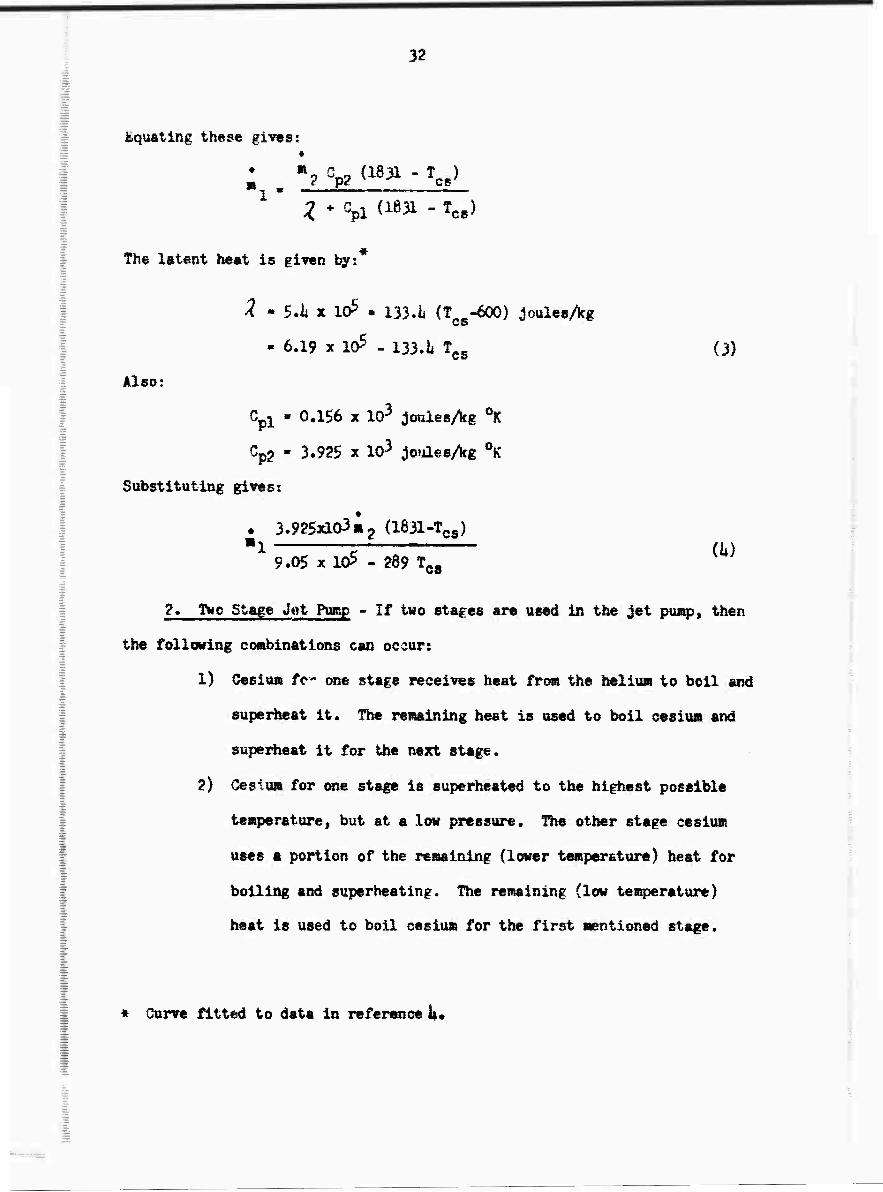
32
Equating these gives: •
; . "g ePg(1831 - V
The latent teat is given bys
2 • 5.1 x 10⁵ • 133.i» (T e^OO) joulesAg
- 6.19 x 10⁵ - 133.1 f.. (3)
Also:
Cpl - 0.156 x 10³ jouiesAg ^
Cp? - 3.92$ x 103 joidesAf 0K'
Substituting gives?
• 3.925x10³ m^ (1831-Tcs) ■1 = (U)
9.05 x 1CP - 289 TC8
2« fwo Stage Jot Pimp - If two stages are used in the Jet pump, then
the following combinations can occur:
1) Ceslu« fc- one stage receives heat from the heliu« to boil and
superheat it. The remaining heat is used to boil oesiun and
superheat it for the next stage.
2) Ceslu» for one stage is superheated to the highest possible
temperature, but at a la» pressure. The other stage cesium
uses a portion of the remaining (lower temperature) heat for
boiling and superheating. The remaining (low temperature)
heat is used to boil cesium for the first mentioned stage.
* Curve fitted to data in reference U.

33
3) fane high t€«peratur« heat is used to superheat cesium for
each stage. First high pressure cesium is heated, and then
lower pre&sure cesium. The remaining teat is utilized to
boil the cesitffl, with the high pressure cesium produced using
the higher quality teat that remains from the superheating
process.
h) lach stage is fed from a common boiler«superheater.
The lest item can be handled by merely splitting up the flow rates
computed for the one stage investigation and need not be considered further
here. The otter possibilities My be sketched as follows;
1) ?)
The number of combinations is
increased to six if the position
of m* and a," are reversed.
This number of combinations causes a rather interesting mess.
Consider a general type of teat exchanger where boiling only takes
place:
■ _3 c^' % Y*S —^ V^ ^ ^
^ £- <>»
'"^ ■_^^,:.:..■-- .-.-

(5)
31*
where 5 refers to the cesims
2 refers to the helimR-ce^iim ffii>.ture {ssm significance as
previously}
T- « »heliuBi" temperature
A heat balance across this system gives
where the b subscript indicates the boiling region.
If a similar exchanger for ruperheating is postulated, then:
*5 Gp5 (Ö5ln - % out) - - fc2 V (rins -^outs) (6)
where the i iiKiicetefi the superheating region
0 ce&fu« temperature.
These two eoustiORs will describe heat interchange between the two fluids
under all conditions subjt^t to the assumptions of no heat loss to the sur-
roundings and thU Ihch numbers are low so that enthalphy can be equated to
heat flow.
Cassiua entering the superheating region will always be at the saturation
iiemperature, which means (&) can be rewritten as
»5 Cp5 ^cs - % out> * »2 V ^ins ^out,) (?)
If, further, we assune the ainüwm ter^erature difference that can be attained
between the cooler and hotter fluids is 25% and if a prim is used to refer
to first stage fluid and a double pri»e to second stage fluid, then the fol-
lowing possibilities exist (see sketches of the three possible combinations):

^
i) r ins
Tin b
f ins 0
%Ottt
9^ in b
T'oat b
2) r ms
«^out
outs
T^outs
%out
'T'out b
T'out b
3) T^
%out
^ outs
T outs
/* out b
7* out b
ie566K
Tins -25 • 1831PK
' outs
ins rr.. - 25
^outs
1856^
1631^
rf, ins
7^ In b
/ins - ?5
T^in b
^cs + 25
18560K
1831^
rU r'ln b
■ r^in b
'Tee* 25
o/e«t -rfks-??
(8)
(9)
fbe noasber of coiabinatlons is doubled if the significance of the prlae is
r€T*i*8ed.
(11)
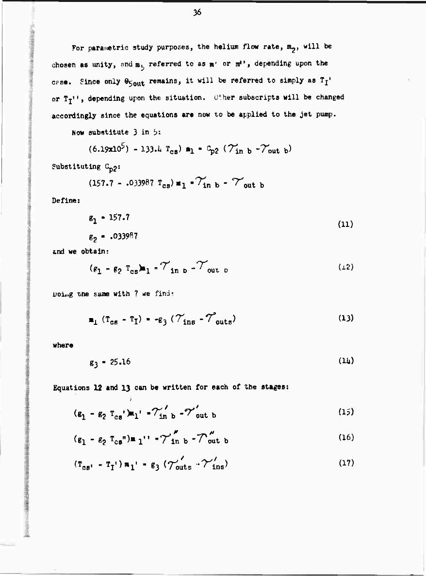
36
For par&iiietrtc study purposes, the hellu» flow rate, a^, will be
chosen as unity, and »^ referred to as «* or a»', depending upon tt»
OPS«. Since only B^^ remains, it will be referred to simply as Tj'
or TTM, depending upon the situation. Other subscripts will be changed
accordingly since the equations are now to be applied to the jet pump.
Now substitute 3 in b:
(6a9xl05) - 133.1 Tcs) mi - Gp2 (7^, b -7^,^ b)
Substituting Cpj:
(157.7 - .033987 Tcg) «^ 'Tin b - 7"^ b
Define:
gi » 157.7
g2 - .0339^7
and we obtain:
^1 - ?? Tcs>»l '^in o -^oux D ^^
iJoi*.g ti» sai» with ? **e finds
where
g3 - 25.16 (lit)
Equatiwis 12 and 13 can be written for each of the stages; i
<«1 * «2 V K' m7to b "^out b ^5)
(g1 - g2 fQ9*)m ^ • -rin b "T^t b ^6)
^cs« -V)»!1 ' *3 <rou'ts -n'ns) ^

37
(W - TT")a es T 1 " ^3
* it
i /oats " ' Ins^ (18)
The follwing are comm-jn to all cases (S^e 8-10. Equations in boxes
represent those to be solved in the order presented):
(19)
(20)
(21)
-rL ■ ^ Tj' • 1831
1 • TI" -rii,
^om 15:
o-i'n K . r', out b «i - g? T C8
Substitute this in 17.
^cs« " TI ) ^ir. b -T'out b)
FVora 16;
n - 2? Tcs'
MLa b -7" out b
g3 ^^outs -"^ins)
?1 * 82 TC3-
Substitute this in 18:
(22)
(?3)
(21)
(TCS" -j^n (T^M b-r0ut.t b)
«l-«2 W «3 (Touts -Tin,) (25)
OR« additional relationship ia n-.i^essary to define the system, and
can be obtained by establishing the tenp^rature difference between primary
and secondary streams at some point. The chosen dif i'erence cannot be
3ö
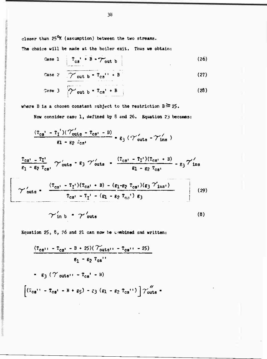
closer than 25°^ (assu^tion) betneen the two streams.
The choice will be »ade at the boiler exit. Thus we obtain«.
Case 1
Case 2
W +B-'re out b
out b * rcs ♦ B
Osse 3 fT^out b ' Tcs' ^B
where B is a chosen constant subject to the restriction B—25.
Now consider case 1, defined by 8 ami 26. Equation 23 becoaes:
(26)
(27)
(28)
(Tcs« -TJ'MT^ -Tcs. -B)
H. * K2 ^cs' • 83 ^outs "'^ins )
" r^T Touts " g3 ^outs » 1 g3^ii f 1 " «2 T( CS' «1 - g2 t
§3 ' ins es'
(Tcs, . TjOCTes» ♦ B) - (f^ TC8l)(g3 r^.) / outs " "~~"
Tcs' "V - (81 " §2 W) 83 (?9)
'/In b " T outs (8)
Equation 25> 8, ?6 arei 21 can now be t^mbined and written:
(TftfiM - ffta. - B + 25)(7rüts,, - Tfi8M - 25) kcs
il * «2 TC8
outs'
f J t
CS"
§3 (T outs'• - Teg« - B)
(W - Tcs' - B ♦ 25) - O ^ " 82 W*) j 7'outs

39
^C8" " Tc8' - B + 25)(Tea«« ♦ 25) - f3 (^ - gj feSM)(T<^ * B)
// sT* m (Tcs -Tcs' - B * g5>(Tgs.. * 25) - g3 (g! - ig TSS«)(TC8' ♦ B) ' outs Tcsw - TC8, - B * 25 - fj Cij - g2 Tcs")
// "Tins ' 7"out b
T^ins - ^5 1
T inh * / outs
(30)
(8)
(21)
(8)
Tout b-W + ^ (6)
«^ and »^B follows irmediately £TO% 27 ami 21*.
For case ?, we have
Tout b • "W + 25 i
Using 9» 25 and 27 we obtain:
^cs« 'T'iLs + ZSKTo^s - TcsB - B)
fl -g2
g3 l ^outs ' / ins^ 'cs
frtm 9, 23 and 27 we find:
Tins - (T s» -Ti'KTcs» ^ B.TC8. - 2?) /
^3 ^§1 - §2 Teg»)
PW» ^.j
II
/outs (Tcs« -rin
#s * 25)(TC
AS + B) - g3 (gi - g2 4 ) 7-J ms
Tss " 'ins + 25 - g- (gj^ - g2 TCSH)
(9)
(31)
(32)
(33)
3 ?

uo
r outs' " ^ins"
-r m b r outs
Tin b
' ^ins" " ?5
it T out b
(9)
» ' and m^ folloir fro« 22 and ?li.
For case 3 we have equation 28 and;
Tout b ■ V + 25 |
; / in b " /out b
(10)
(10)
From 23 and 10:
OW -Tx'Xr^-^b) /
' C^s -Tins) «3 ^1 " g? Tcs,
rL-r4s * ^-n.x^ts-^utb) «3 («1 -g? Tcs')
Fro« 25 and 10
(3i*)
^ (TcsB -rins**25Hri;b.r;utb)
n - ^2T ■ €3 ( Touts "Tins-) cs
// r inSH . g3 ^1 - «2 ^s^ r"outs - ^cs" * 25)(rinM b - ^ut b)
7^ T '3(^ -ig^t-) -( riiS- routb)
(35)

Ul
How eouate 3? and 2ht
§3 (§1 - %2 TCsO ins
g3 (gi ~ gg Tc8H) rout8» - (TC/ ♦ 2g)(r1/; b .-r^t b)
€3 (gi - g? Tcsw) - (?ln b * ^oit b)
Tea« ' Tl« g3 fgl -^cs')
// */ . ^3 ^1 * g? Tc8
H) ^outs / outs
g3 ^il " g2 Tcsn) " ^in b " "^out b)
-r, Ins g3 (gx - gp TC8')
/ out b -
(Tc8" + 25) (Tiab - rout b)
g3 (gi - g? TC8M) - ( rÄ b - rSrt, b)
/outs
^/ Tcsf - Tj» / '^ins* SL 1 7-outb
63 (gl - g2 TC8') s
_ (TC8M*25) < r^b - reut b) g3 ^«l-«2 Tcs«)-(ri*n b-Zo'ut b)
W - ^i' g3 {gl * g2 ^t")
^ Tin b " Tout b) ; g3 <il-ga Tcs') g3 (fi - gg TC5«) -
M T^ins c*n now be found from
35
TJ»n
r^uts -y^i
/ In b « rout
(10)
(10)
and fc' erd »^^ follow fro« ?2 and 2«.

U2
BIBLICXgUPHY OF REFBtlllCES
1« Martin Company Semi-Annual Technical Suramary Report on Research Program
on Application of Jet Compressor to MPD Electrical Power Generation,
MND-312i4, January 196ii.
2, C. Shih, »A Study of Closed Cycle M?D Power Qenerator Ccarpatible with
Jet Compression," Proceedings of the International Symposium of ffü)
Electrical Power Generation, July 196U, Paris, France.
3. S. S. Eichacker & H» Hog* "Jet Con^ressor Efficiency as Influenced by
the Nature of the Driving and Driven Gases," August I960, Journal of the
Aero Space Sciences, V« 27, No« 8,
U» W. 0. Weatherford, Jr., J. C. Tyler and P. M. Ku, "Properties of Inorganic
Energy Conversion and Heat Transfer Fluids for Space Application,11 Southwest
Research Institute, WADD Technical Report 61-y6,

U3
DISTRIBUTION LIST
No» Copies
Office of Naval Research 6 Power Branch (Code k29) Washington, D. C, ?0360
Attn: John A. Satkwski
GoaHnanding Officer 1 Office of Naval Research Branch Office Box 39 Navy #100 Fleet Post Office Hew York, New York
Chief, Bureau of Ships 1 Washington, D. C. 20360
Attnt Dr. John Huth Chief Scientist
U, S» Naval Research Laboratory 6 Washington, D, C. 20390
Attn: Technical Inforaation Division
Director 1 Advanced Research Projects Agency Material Sciences Division Washington, D. C. 20301
Wright-Patterson Air Force Base 1 Aeronautical Systems Division Ohio Attn: Don Wamock {ASRKFP-2)
Air Force Office of Scientific Research 1 Washington 25, D. C.
Attn: Dr. Milton M. Slawsky
0. S. Naval Ordnance Test Station 1 Propulsion Applied Research Group Oiin* Lake, California Attnt Mr. Leroy J. Krzycki (Gode U506)
Anay Natick Laboratory 1 Pioneering Research Livision Natick, Massachusetts
Attn: Mr. Harold J. Hoge

Uli
I
Roiae Air DeTelopaent Center 1 Rose, New York
Attn: Mr. F^ank J. Ifellura
U. S. Navsl Ordnance Laboratoi7 NA Division White Oak, Maryland
Attnt Wallace Knutsen 1 Library 2
Defense Docmaentation Genter ?0 Cajwrwi Street Alexandria, Virginia ?2311i
U. S. Äray Research & Developiaent Laboratory 1 Fort Belvoir, Virginia Ättns F^ank Shields (ERD-EP)
National Aeronautics and Space Administration Lewis Research Center 21000 Brookpark Road Cleveland 35, Ohio Attnt John Stevens 1
Dr, B, Lubarsky 1
U. S. Atomic Energy Coramission 1 Division of Reactor Develo|»ent Direct Energy Conversion Section, RD| AED Geraantown, Maryland
Dr. T. Brogan 1 AVCO-Everett Research Lsboratory 2385 Revere Beach Parkway Everett, Massachusetts
Dr. B. Zauderer 1 General Electric Company Valley Forge Space Technical Center Philadelphia 1, Pennsylvania
Dr. M. I. Tal&at 1 Department of Mechanical Engineering University of Maryland College Park, Maryland

» -
U5
Dr* W, D, Jackson Electrical Snginterlnf Dtp&rtaent MsssÄChusetts Institute of Technoloßr Ga^ridfe 39, Massachusetts
Dr. B. 0. Undley Nuclear Research Centre C. A. Parsom* Coiapany, Ltd. Fossway, Newcastle Upon Tyne 6 ^gland
Dr. Robert Eustis Bierwofcienees Division Stanford University Stanford, California
Dr. Richard Schamberg Rand Corporation 1700 S. Main Street Santa Monica, California
Dr. W. S. Eiamerich Wesiinfhouse Research Laboratories Beulah Road, Churchill Borough Pittsburgh 35» Pennsylvania
Dr. R. T. Schneider Allison Division General Motors Corporation Indianapolis, Indiana
Dr. D. 0. Elliott Jet Propulsion Laboratory Pasadena, California
Dr. Phil Hill Department of Mechanical Engineering Massachusetts Institute of Technology CsMbndge, Massachusetts 02139
Dr. John J. Connelly, Jr. State university of New York College at Fredonia Physics Depart«ent Fi-edonia, New York 1^063
r L