mx510/mx512 operator & installation manual · mx510/mx512 operator & installation manual....
TRANSCRIPT

Product InformationThe model and serial number of your instrument are given onthe instrument. Enter the model and serial number in thespaces provided below. Always refer to this information whenyou contact your dealer.
MX51_ CDU Serial No.:_________________
Antenna Model: __________________
Antenna S/N: __________________
Copyright April, 2008
Doc. P/N 510 100 2002GTD
Models Covered are:MX51x GPS/DGPSMX51x/BRMX51x/BRIMMX51x/MUC
IMPORTANT NOTICE!!THE MX51X IS AN AID TO NAVIGATION ONLY. UNDER NO CIR-CUMSTANCES SHOULD IT BE USED IN LIEU OF AUTHORIZED GOV-ERNMENT CHARTS. ITS ACCURACY CAN BE AFFECTED BY MANYFACTORS SUCH AS EQUIPMENT DEFECTS, ENVIRONMENTALCONDITIONS, OR IMPROPER OPERATION. THE USER IS RESPON-SIBLE FOR SAFE NAVIGATION OF THE VESSEL. THIS INCLUDESCONSULTING AUTHORIZED GOVERNMENT CHARTS AND EXER-CISING COMMON PRUDENCE AND NAVIGATIONAL JUDGEMENTAT ALL TIMES.
MX510/MX512Operator & Installation Manual

Symbols Used In This ManualDangerIndicates an imminently hazardous situation which, if not avoided,will result in death or serious injury.
Warning
Indicates a potentially hazardous situation which, if not avoided,could result in death or serious injury.
Caution
Indicates a potentially hazardous situation which, if not avoided, mayresult in minor or moderate injury and/or appreciable material, finan-cial and environmental damage. This symbol is also used to alert againstunsafe practices.
Important paragraphs which must be adhered to in practice, as theyenable the product to be used in a technically correct and efficientmanner.
This manual contains important safety directions as well as instruc-tions for setting up the instrument and operating it. Read carefullythrough the Operator’s & Installation Manual before you switch onthe instrument.
!
!
!

Scope Of This ManualThis manual covers the operation and installation of both the MX510and MX512 CDU models. The keypad operation of these models areidentical.
We have attempted to take care and develop manuals which providein-depth information. Where possible, we have attempted not only todescribe what you see on the screen, but how to understand and useit as well. Obviously, we can’t teach you how to navigate, but we canhelp make your work more thorough and enjoyable. Throughout themanual, you will find helpful hints about the interaction of variousfunctions. In a piece of equipment that has the many capabilities ofthis receiver, important details can sometimes become obscured in oneor two lines of text. In our effort to ensure you get the most out of thisdocumentation, and to protect against important details becoming lost,don’t be surprised if you see the same or similar information more thanonce.
This manual is organized into two main parts. The first section dealswith the operation while the second section talks about the installa-tion and electrical interface. We start by describing first the MX51xmodels covered in this book, then the special front panel featuresincluding the traffic light indicator and USB connector. The sectionsthat follow detail each primary function as it is presented on the frontpanel (i.e. NAV, RTE, WPT, PLOT, ...CFG). The appedixes describe im-portant details about special functions and installation of the MX51x.
We hope you find the manual enjoyable and informative reading. Asalways, we welcome your comments on improving our products ormanuals. We wouldn’t mind if you wrote to tell us that we did the jobright the first time either. You can find a Reader Comment Card at theback of the manual.
Related DocumentsMX51x Quick Reference Guide (P/N 510 100 2003)

How To Contact Us?
Contact your local SIMRAD Marine dealer for:
• Installation, Service, & Technical Support• Sales of Accessories• Hardware and Software Upgrades
Unlike many other consumer electronics industries which onlysell consumer electronic devices, your marine dealer is often yourbest advisor for installation and service of your new GPS receiver.We strongly encourage you to utilize the knowledge and experi-ence of your sales and service dealer.
Should you need to contact us directly for new sales, upgrades,repair service, or technical support, we can be reached at thefollowing:
USA Office:
SIMRAD23868 Hawthorne Blvd., Suite 201Torrance, California 90505-5908USA
+1-310-791-8213 Telephone+1-310-791-6108 Fax
Europe:
NAVICO UK Ltd.Premier Way, Abbey ParkRomsey, Hampshire S051 9DHUnited Kingdom
+44 (0) 1794 510010 Telephone+44 (0)1794 50006 FAX
Internet:
www.mx-marine.com

Table of Contents
About GPS Navigation ................................................................................. 1Special Notes ....................................................................................... 2
GPS .................................................................................................. 2DGPS................................................................................................ 2Charts and Navigational Aids ............................................................. 2Compass Safe Distance .................................................................... 2
Functional Description ................................................................................. 3CDU Configurations .............................................................................. 3
Basic CDU configuration................................................................. 3MX51x DGPS ................................................................................. 3MX51x/BR ...................................................................................... 4MX51x/BRIM (Backup Receiver Integrity Monitor) ........................... 4MX51x/MUC (Multi Unit Control) ..................................................... 5
DGPS Beacon System ............................................................................... 6Keypad & Display Description ..................................................................... 7
Differential GPS Traffic Light Operation: ................................................ 8GPS Traffic Light Operation: ................................................................. 9The Display: ....................................................................................... 10
+ Virtual Softkeys: .................................................................... 11
The Function Keys: ............................................................................ 11
F1 Programmable Keys (F1 to F4) ................................................ 12
Mark / MOB Key .................................................................... 12
5GOTO
MN0 GOTO................................................................................... 13
POWER ON/OFF .................................................................. 13
CLR (CLEAR) ........................................................................ 14
CURSOR................................................................................ 14
ENTER ................................................................................. 14

1NAVABC
FUNCTION Keys ............................................................. 15
Automatic Identification System (AIS) .............................. 16
1NAVABC
Navigate ........................................................................... 17
Route ............................................................................... 27
Waypoint ........................................................................ 46
Mark / MOB ..................................................................... 68
5GOTO
MN0 GOTO .............................................................................. 69
4PLOT
JKL Plot .................................................................................. 72
Man Over Board ............................................................... 79
6AUX
PQR Auxiliary ........................................................................... 81
Position ............................................................................ 89
GPS ................................................................................. 93
Configuration ................................................................... 101
Alarms .............................................................................. 101Anchor - Anchor Watch Alarm ........................................... 102COG SOG - Course & Speed Filter Settings & Setup ........ 102Compass - External Compass Input & Magnetic VariationTable ................................................................................. 103Datum - Current Position Calculation ................................. 105Depth - NMEA Input Control ............................................... 105DGPS - DGPS Configuration ............................................. 107DR - Dead Reckoning ........................................................ 109Dual Control - Dual Station Control .................................... 109

GPS - Elevation Mask Control ............................................110Initial Pos - Initial Position Entry ......................................... 111LAN - Local Area Network...................................................112LAN Output (NMEA 0183 OVER IP) ...................................113Language - Language Configuration ....................................114Lighting - Display/Keyboard Light & Contrast Control .......... 114Log - Speed Log Input (Pulse or NMEA 0183) .....................115Log Pulses - GPS SOG Log Pulse Output ......................... 116LORAN-C Integration .......................................................... 117Memory ............................................................................. 121Navigation - Navigation Method & Waypoint Pass CriterionControl .............................................................................. 121NMEA Out 1 to n - NMEA 0183 Output Data Control ......... 125Other Special Cases Affecting NMEA 0183 Records: ......... 130Operation - General Setup and Control Settings ................ 131Organizer - Automated Message Reminders ...................... 132Position - Positioning Reference, Mode, & Alarm Control ... 133Printout (n) - Printer Output Control ................................... 135ROT (Rate of Turn) ............................................................. 137Security ............................................................................. 137Serial I/O ........................................................................... 138USB - USB Mass Storage Configuration ............................ 139VGA .................................................................................. 141Wpt & Rte Input - Uploading Waypoints into the MX51x .... 142
APPENDIX A - DATUM LIST .................................................................... 143APPENDIX B - ENGINEERING MODE .................................................... 145
AUX7 - Unit Information & Self Test ................................................... 145CDU Cold Start - Clearing Memory to Factory Default ....................... 147GPS - GPS CDU Troubleshooting ..................................................... 149GPS3 - Visible Satellite Information .................................................. 149GPS4 - GPS Position Uncertainty .................................................... 150Antenna Reset Tools ......................................................................... 150
APPENDIX C - MULTIPLE UNIT CONTROL (VIA LAN) ............................ 151APPENDIX D - DEMONSTRATION MODE .............................................. 157APPENDIX F- INSTALLATION SECTION ................................................. 159SECTION 1 - LIST OF COMPONENTS ................................................... 161SECTION 2 - TECHNICAL SPECIFICATIONS .......................................... 165SECTION 3 - INSTALLATION NOTES ...................................................... 171
GENERAL ........................................................................................ 172Electronic Connections ..................................................................... 172Wire Preparation Procedure .............................................................. 173PWR/DATA Cable (6-Pairs Twisted): ................................................. 173

AUX Cable (4-Pairs twisted): ............................................................. 173External Power ................................................................................. 174ANTENNA INSTALLATION ................................................................ 174Antenna Location .............................................................................. 174Antenna Options ............................................................................... 174Antenna Connector ........................................................................... 175Antenna Cable Options ..................................................................... 175External Differential Connection ........................................................ 176MX51X NAVIGATOR INSTALLATION ................................................. 177Gimbal Mounting .............................................................................. 177Flush Mount Frame .......................................................................... 177Turning Power On and Off ................................................................. 177EQUIPMENT INTERFACING ............................................................. 178Introduction ....................................................................................... 178External Man Over Board & Event ..................................................... 179Speed Over Ground Pulse Output ..................................................... 179External Alarm Output ...................................................................... 180NMEA Interface ................................................................................. 181NMEA Interface to other Equipment .................................................. 181MX51x NMEA 0183 Sentences ......................................................... 182Data Format ..................................................................................... 182NMEA Output Sentences .................................................................. 183Input NMEA 0183 Sentences ............................................................ 184Viewing Input Data ............................................................................ 185Dual Control (Remote) Interface ........................................................ 186MX51x/BRIM (Backup Receiver with Integrity Monitoring) Feature ..... 189Troubleshooting Guide ...................................................................... 190Memory Backup Battery ................................................................... 192Backup Battery Replacement ........................................................... 192MX51x PC Interface .......................................................................... 192Software Update Procedure .............................................................. 193Memory Clear Procedure: ................................................................. 194USB Device Formatting Procedure: ................................................... 195USB Flash Drive Hardware Compatibility List .................................... 196
SECTION 4 - MECHANICAL AND INSTALLATION DRAWINGS .............. 197SECTION 5 - MX 510 ELECTRICAL INSTALLATION DRAWINGS ........... 209SECTION 6 - MX 512 ELECTRICAL INSTALLATION DRAWINGS ........... 221

Version 3.0 1
About GPS Navigation Operator�s Manual
About GPS Navigation
This GPS receiver is a precision navigation instrument utilizing thelatest technology available today to provide optimum performancefrom the GPS satellite and Beacon land signals received. As with allother forms of radio signals, the ultimate navigation result is depen-dent upon the quality of these signals. Radio signals may, on occa-sion, be distorted, jammed, or otherwise incorrect. As a result, yourposition accuracy may occasionally be less than that which can nor-mally be expected.
The Navstar Global Positioning System, commonly referred to as GPS,is a satellite navigation system developed by the U.S. Department ofDefense to provide both military and civilian users with highly accu-rate, worldwide, three dimensional navigation and time. By receivingsignals from orbiting GPS satellites, authorized users are able to con-tinuously navigate with an accuracy on the order of 5 meters 2D RMSor better
A technique referred to as Differential GPS (DGPS), allows users toobtain maximum accuracy from the GPS system. DGPS requires the useof two GPS receivers. One receiver, known as the Reference Station, isplaced at a surveyed location, the coordinates of which are preciselyknown. The purpose of the differential GPS system is to use the refer-ence station to measure the errors in the GPS signals and to computecorrections to remove the errors. The corrections are then communi-cated in real-time to the navigators, where they are combined with thesatellite signals received by the navigators, thereby improving theirnavigation or positioning. The geographic validity of these correc-tions decreases with distance from the reference station, but the cor-rections are valid for navigators hundreds of kilometers from the refer-ence station.
Marine radio beacons operating in the 283.5 to 325.0 KHz frequencyrange are in widespread use for direction finding in coastal navigation.Because the beacon system has been in place and widely used formany years, it provides an effective means for the transmission ofDGPS signals. Depending on their local environment and power out-put, their signals may be usable to several hundred miles. Marine bea-cons provide an economical means of obtaining DGPS accuracy forcoastal navigators. GPS receivers with built-in beacon receivers aredesigned to provide low cost reception of DGPS corrections broad-cast (normally free of charge) by coastal authorities.
�

2 Version 3.0
Operator�s Manual About GPS Navigation
Special Notes
GPS
Never rely solely on any single navigational aid. Always use whateverinformation is available, and cross-check information when possible.GPS expected position accuracy is better than 30 meters (95% of thetime) but may be up to 100 meters occasionally. The derived speed andcourse readings may be hampered accordingly. The GPS system wasdeclared operational in 1994; however, the system�s availability andaccuracy are subject to change at the discretion of the US Departmentof Defense.
DGPS
This GPS receiver�s position accuracy is improved to 2 meters or betterfor 95% of the time, subject to the availability, accuracy, and control ofthe DGPS correction transmission from the Beacon Station.
The beacon radio signal which carries the DGPS corrections may behampered by weather conditions such as heavy rain, snow, and thun-der storms. The beacon radio signal may also be interrupted by power-ful radio transmitters operating in long wavelength bands.
Charts and Navigational Aids
Positions obtained from charts are not always as accurate as yournavigator (due to environmental changes, the dates of charts, anddatum offsets if the datum differs from the one in use by the naviga-tor). The position of a floating aid can differ due to tide, set and drift
Compass Safe Distance
1 meter.
�
�

Version 3.0 3
Functional Description Operator�s Manual
Functional Description
The MX51x and MX512 Navigation CDU models are generally de-scribed in this manual as MX51x Control and Display Unit (CDU).Their general operating features are identical and will be described incommon details in this manual. Specific model number will be called inareas where they differ from one another.
CDU Configurations
The MX51x and MX512 Navigation System is available in several con-figurations. Please refer to the Auxiliary Unit Information section ofthe manual to view sample screens to identify your particular model.Described below are the various configurations and their differences.
Basic CDU configuration
The MX510 has two (2) bidirectional user NMEA ports while theMX512 has nine (9) bidirectional user NMEA ports. Both models haveone (1) high-speed Local Area Network (LAN) port and two USB ports.The basic GPS navigation model includes the CDU and a smart GPSantenna
�����
����� ��������
Basic MX510/512 GPS Configuration
MX51x DGPS
The MX51x DGPS model is supplied with a smart DGPS antenna withbuilt-in Beacon receiver (MX521A). The smart DGPS antenna unit canachieve better than 2 meter accuracy in areas with good beacon differ-ential coverage.

4 Version 3.0
Operator�s Manual Functional Description
�����
������ ��������
Basic MX51x DGPS Configuration
MX51x/BR
The MX51x/BR configuration is a dual-control system where twoMX51x (one operating as a master and the other as a slave) is supplied.Only one MX521A smart DGPS antenna is required. The antenna unitis connected only to the master unit. The two MX51x CDUs communi-cate via the high-speed LAN port.
Note: LAN port must be setup before enabling this feature. The units
can be connected together using an ethernet crossover cable (when
connected directly) or through a hub/switch/router. See page 112 of
this manual for setup details.
������������������
������ ��������
������������������
������������� ��
MX51x BR Beacon and Remote Configuration
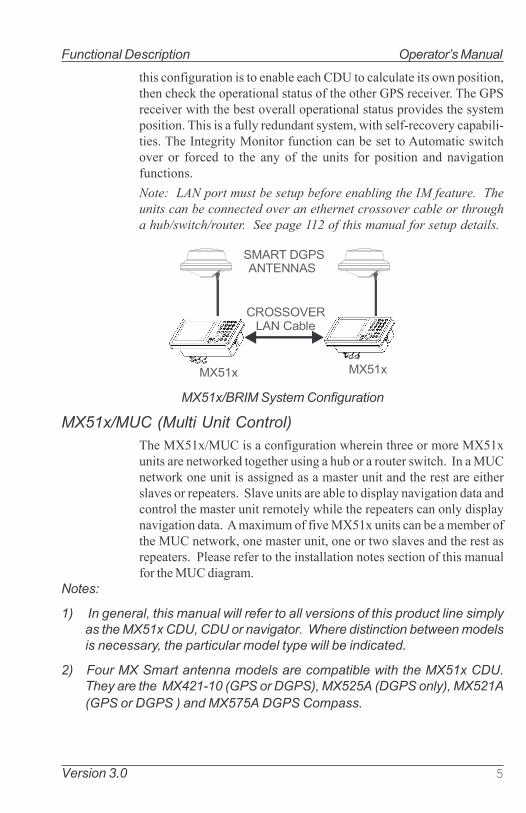
MX51x/BRIM (Backup Receiver Integrity Monitor)
The MX51x/BRIM is an enhanced Dual-Control configuration whereintwo MX51x CDUs and two MX521A smart DGPS antennas are sup-plied. The two MX51x units are connected in dual-control configura-tion but they operate as independent navigator units with dedicatedantennas. The Integrity Monitoring (IM) feature is a software optionthat works in the MX51x CDU hardware.
This configuration allows data to be shared between two remotelyseparated stations (i.e. navigator�s station and helmsman�s station),with independent access to various information fields. The purpose of
Version 3.0 5
Functional Description Operator�s Manual
this configuration is to enable each CDU to calculate its own position,then check the operational status of the other GPS receiver. The GPSreceiver with the best overall operational status provides the systemposition. This is a fully redundant system, with self-recovery capabili-ties. The Integrity Monitor function can be set to Automatic switchover or forced to the any of the units for position and navigationfunctions.
Note: LAN port must be setup before enabling the IM feature. The
units can be connected over an ethernet crossover cable or through
a hub/switch/router. See page 112 of this manual for setup details.
�����
������ ���������
�����
������������� ��
MX51x/BRIM System Configuration
MX51x/MUC (Multi Unit Control)
The MX51x/MUC is a configuration wherein three or more MX51xunits are networked together using a hub or a router switch. In a MUCnetwork one unit is assigned as a master unit and the rest are eitherslaves or repeaters. Slave units are able to display navigation data andcontrol the master unit remotely while the repeaters can only displaynavigation data. A maximum of five MX51x units can be a member ofthe MUC network, one master unit, one or two slaves and the rest asrepeaters. Please refer to the installation notes section of this manualfor the MUC diagram.
Notes:
1) In general, this manual will refer to all versions of this product line simply
as the MX51x CDU, CDU or navigator. Where distinction between models
is necessary, the particular model type will be indicated.
2) Four MX Smart antenna models are compatible with the MX51x CDU.
They are the MX421-10 (GPS or DGPS), MX525A (DGPS only), MX521A
(GPS or DGPS ) and MX575A DGPS Compass.
6 Version 3.0
Operator�s Manual DGPS
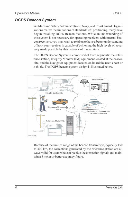
DGPS Beacon System
As Maritime Safety Administrations, Navy, and Coast Guard Organi-zations realize the limitations of standard GPS positioning, many havebegun installing DGPS Beacon Stations. While an understanding ofthis system is not necessary for operating receivers with internal bea-con receivers, you may want to read on to have a better understandingof how your receiver is capable of achieving the high levels of accu-racy made possible by this network of transmitters.
The DGPS Beacon System is comprised of three segments: the refer-ence station, Integrity Monitor (IM) equipment located at the beaconsite, and the Navigator equipment located on board the user�s boat orvehicle. The DGPS beacon system design is illustrated below.
�!"�#$��%�$$
������������
����������� ����� � � ��� �
��� �����
��� � � � � ��
�� ���������������
�������� �� � ����� ����
�����
�������������������
�������������������
�����
��� ��������������������
����������� ������
�
Because of the limited range of the beacon transmitters, typically 150to 400 km, the corrections generated by the reference station are al-ways valid for users who can receive the correction signals and main-tain a 5 meter or better accuracy figure.

Version 3.0 7
Keypad & Display Description Operator�s Manual
Keypad & Display Description
The MX51x and MX512 keypad operation and traffic light indicationsare identical. The Traffic Lights on the right side of the display will tellyou how your navigator is operating.
&������
��� �!�
!��"��'
(�#$�%&#
'(
')
'*
'+
��$�$��,
)��- *
�+� ��,
�+������'-�,�
�''+���+�.� ������/���-�,�
'���+��-�,�
��/� ������-�,�
����-�,
�0�
��,1�+�.
��/1��-
������������ ��������
Note: You need to take care in reading the traffic light indications, as there
are overlapping possibilities between the GPS and DGPS modes. If
you are unsure of the current operating mode, select the CFG func-
tion key and scroll down to the DGPS selection. If the DGPS mode
is selected to anything other than Off, then follow the Differential
GPS Traffic Light Operation. If the DGPS mode is selected to Off,
then follow the GPS Traffic Light Operation.

8 Version 3.0
Operator�s Manual Keypad & Display Description
Differential GPS Traffic Light Operation:
Red Flashing
Not tracking satellites (no position update). This is normal for thefirst 2 minutes or so when turning the unit on. The very first time youturn the unit on, or if the memory is reset or lost, this condition is alsonormal. Allow the receiver to run for at least 20 minutes under thesecircumstances. If it still does not change to Red Solid, refer to thetroubleshooting section in the Appendix G of this manual. An iconsimilar to the one at left will be displayed in the upper left corner ofscreen.
Red/Yellow Solid
Dead Reckoning . When normal GPS or DGPS operation is not avail-able, this LED sequence is provided to quickly identify the DR naviga-tion mode. A DR indicator is also displayed on all screens.
Red Solid
Tracking one or more satellites (no position update). This is alsonormal for the first 2 minutes or so when turning the unit on. The veryfirst time you turn the unit on, allow the receiver to run for at least 20minutes after changing to Red Solid to collect an almanac from thesatellites, regardless of whether a position fix has been calculated ornot. This is also a normal indication if the HDOP is greater than 10, ifthe receiver is tracking too few satellites, or for other reasons as well.Read the GPS and DGPS function screens for more information.
Yellow/Green Solid
GPS position update; DGPS corrections are not being received. Youmay see this from time to time during normal operation. It usuallyoccurs when the beacon signal is not available (either it is being blockedby terrain or a local object or you are out of range of the transmitter)and/or you are tracking 3, 4, or 5 satellites, and the satellites have poorgeometry relative to your position. The condition will normally goback to green solid, when it picks up another beacon station. Thefactory default level for dropping DGPS corrections is 600 seconds.During this period, your positioning information maybe less than op-timal, and position accuracy may be off by as much as 5 meters. Pressthe GPS function key and refer to the DGPS section in this manual forguidance if this light condition occurs.
�

Version 3.0 9
Keypad & Display Description Operator�s Manual
Yellow Solid
DGPS position update with poor HDOP value. You may see this fromtime to time during normal operation. It usually occurs when you aretracking 3, 4, or 5 satellites, and the satellites have poor geometryrelative to your position. The condition will normally go back to GreenSolid when it picks up another satellite or the geometry of the existingsatellites improves. The factory default level for this indication is withan HDOP of 4 to 10. During this period, your positioning information isless than optimal, and position accuracy may be off by as much as 5 to10 meters. You can press the GPS function key and refer to the GPS
section in this manual for guidance if this light condition occurs.
Green Solid
DGPS position update with HDOP value less than 4. This is thenormal operating condition. Position accuracy is normally better than3 meters. Keep in mind that position accuracy is only as good as thecorrections received, their age, your distance from the reference sta-tion, and the geometry of the satellites. This is the normal operatingcondition and no icon will be displayed.
GPS Traffic Light Operation:
Red Flashing
Not tracking satellites (no position update). This is normal for thefirst 2 minutes or so when turning the unit on. The very first time youturn the unit on, or if the memory is reset or lost, this condition is alsonormal. Allow the receiver to run for at least 30 minutes under thesecircumstances. If it still does not change to Red Solid, refer to thetroubleshooting section in the Appendix G of this manual. An iconsimilar to the one at left will be displayed in the upper left corner of thescreen.
Red/Yellow Solid
Dead Reckoning . When normal GPS or DGPS operation is not avail-able, this LED sequence is provided to quickly identify the DR naviga-tion mode. A DR indicator is also displayed on all screens in the upperleft hand corner of the display.
Red Solid
Tracking one or more satellites (no position update). This is alsonormal for the first 2 minutes or so when turning the unit on. The veryfirst time you turn the unit on, allow the receiver to run for at least 20

10 Version 3.0
Operator�s Manual Keypad & Display Description
minutes after changing to Red Solid to collect an almanac from thesatellites, regardless of whether a position update has been calculatedor not. This is also a normal indication if the HDOP is greater than 10.The HDOP value can be read in the GPS function screens.
Yellow Solid
GPS position update has a poor HDOP value. You may see this fromtime to time during normal operation. It usually occurs when you aretracking 3, 4, or 5 satellites, and the satellites have poor geometryrelative to your position. If you are patient, the condition will normallygo back to Green Solid when you pick up another satellite or the geom-etry of the existing satellites improves. The factory default level forthis indication is with an HDOP of 4 to 10. During this period, yourpositioning information is less than optimal, and position accuracymay be off by as much as 10 to 30 meters. You can press the GPS
function key and refer to the GPS section in this manual for guidanceif this light condition occurs.
Green Solid
GPS position update with HDOP value less than 4. This is the normaloperating condition. Position accuracy is normally between 3 to 5meters, but can be out as much as 30 meters. Keep in mind that posi-tion accuracy is always only as good as the geometry of the satellitesand the navigation information provided by the satellites. This is thenormal operating condition and no icon will be displayed.
The Display:
The MX51x uses a 6.4� monochrome quarter VGA LCD display. Itprovides optimum viewing in virtually all angles and lighting condi-tions. To change the display contrast or backlight condition, select theCFG function key and scroll down to the Lighting menu choice. Referto the CFG section of the manual for a complete description of menu
options. The DAY/NIGHT dual function key allows you to quickly
change between day or night time screen viewing.
Information displayed on the screen is normally divided into windows,similar to what you might see on a normal computer. Each screen has a
page number located in the upper left hand corner (i.e. ). Thesepage numbers are there to help you find the information you need, andto help us guide you on the rare occasion that you might request ourassistance.

Version 3.0 11
Keypad & Display Description Operator�s Manual
With the exception of a portion of the PLOT and MOB screens whichuse the UP and DOWN arrows to zoom in or out, all of the screensrequire that you press the EDIT (Edit Mode) function key before youare allowed to change data on the screen. You can use the cursor key(the big key with the arrows pointing in four directions) to move be-tween edit fields or menu choices on most screens when in the editmode. When you are not in the edit mode, you can use the cursor toscroll between screens (i.e. NAV1, NAV2, NAV3, ...) or to move up anddown on screens (like the menu bar in the CFG screen).
+ Virtual Softkeys:
The Edit key activates or deactivates the virtual softkeys and editfields within any screen where editing is appropriate. You will quicklylearn that this is an important operating feature in the unit. Press theEDIT key when you want to start editing a screen and again when youhave finished editing. If after editing you press a function key andnothing seems to happen, check to make sure you didn�t accidentallyalter your information and press the EDIT key to end editing. Someedit screens provide an Escape softkey. If you decide for some reasonthat you don�t want to use the changes you have made, highlightingthe Escape softkey and pressing the ENT key will restore the originalinformation. However, once you press the EDIT key, all changes areaccepted and the original data is lost.
The virtual softkeys at the bottom of the display are so named becausetheir purpose changes from one menu (or screen) to the next. All of thescreens require that you press the EDIT (Edit Mode) function keybefore the virtual softkeys can be accessed. Then use the LEFT andRIGHT cursor arrows to highlight the desired virtual softkey and pressthe ENT key (refer to pg. 14) to choose it. Don�t forget to press theEDIT function key when you have finished to exit.
The Function Keys:
The MX51x has 17 function keys. These keys are used to directlyaccess various navigation, positioning, GPS, configuration and otherscreens. One function key is used to mark your present position, andto activate the Man-Over-Board feature when depresses for a fewseconds.
The ten function keys with alphanumeric designations are describedin the following chapters. The MARK/MOB keys and the GOTO keysare described below.

12 Version 3.0
Operator�s Manual Keypad & Display Description
The function keys are also used in the edit mode to enter alphanumericinformation for route and waypoint names.
'( Programmable Keys (F1 to F4)
These keys are like the memory buttons in car radios. They can beprogrammed to quickly bring-up a particular screen that you use all thetime. To memorize a particular screen, all you need to do is first selectthe desired display using the regular function keys, then press andhold the F1 (or another F# key) for about 3 seconds until a series ofshort beeps is sounded. The function key is now programmed. Thenext time you wish to bring up that particular screen, just press the F#key momentarily. You may reprogram any F# key at will.
Mark / MOB Key
This dual function key when pressed momentarily marks your presentposition and stores it at the next available waypoint location in thewaypoint bank. A window pops up on the screen to confirm your keydepression, and to tell you where the mark position is being stored.You can go into the WPT menu and edit the coordinates or descriptionlater. The CDU is also capable of performing this function from a re-mote contact closure input via the AUX Cable (MOB/Event) wire. Re-fer to the Appendix G of this manual for interface instructions.
When depressed for 3 seconds, this function key activates a numberof automatic MOB functions:
Ø Most obviously, it brings up an MOB1 plot screen. This is anautomatic scaling screen which selects the best zoom level todisplay your present position and the MOB position. In addition,the MOB position is displayed in the upper left corner, so that youcan quickly read the coordinates to others who may be availableto render assistance. This plot screen also provides the range andbearing back to the MOB position, as well as your present courseover ground.
Ø The MOB position, date and time are stored in the Waypoint Bankfor future reference (e.g. log book entries).
Ø Navigation data output on the NMEA ports (i.e. BWC and BWR),are changed to reflect the current urgent situation. This way, otherinterfaced equipment can also help guide you back to the MOBposition. When the MOB condition is canceled via a MOB screensoftkey, the NMEA sentences will automatically revert to the ac-
Version 3.0 13
Keypad & Display Description Operator�s Manual
tive route information. Don�t forget to cancel the MOB so your
interfaced equipment will read the correct data!
Ø The MOB function key and remote MOB input are disabled fromsubsequent activation, until the MOB Cancel softkey is selected.
Ø Other functions such as Position and Navigate can still be ac-cessed; however, the screen will revert to the MOB Plot screenafter 30 seconds. Bearing and distance information in these otherscreens relate to the MOB position, not the next waypoint in theactive route, until MOB is canceled.
To cancel a MOB condition, make sure you are in the MOB Plot screen.Press the EDIT function key, then press the ENT key to select theCancel MOB softkey.
The MX51x CDU isalso capable of performing the MOB function froma remote switch. If the switch is pressed for less than 2 seconds, theaction is registered as a Mark Position. If the switch is pressed for 3seconds, the MOB function is activated. Refer to the Appendix G ofthis manual for interface instructions.
�$�$
GOTO
This function key allows you to quickly create a route from your presentposition to waypoint or a route. This single waypoint route can use anexisting waypoint from the Waypoint Bank, or you can quickly createone by either defining the appropriate coordinates or specifying arange and bearing.
Be careful when you use this selection, as it will erase your currentactive route when it creates the new one. Read through the ROUTE
and PLOT sections of this manual to find other ways to use this keywithin an active route.
POWER ON/OFF
This DUAL function key turns the unit on and off. When depressedmomentarily while the unit is on, you will be prompted to select a YES
or NO softkey to confirm your action. This is known as a software
power off.
If the operating program should hang up for any reason, you can alsoperform a hardware power off by pressing the power key for about 5seconds. When the GPS is turned off using this technique, you cannot reapply power for 10 seconds.

14 Version 3.0
Operator�s Manual Keypad & Display Description
Note: An occasion may arise when you need to reset the memory back to the
factory default values. Doing this will cause the CDU to lose all of your
defined settings, as well as all 2,000 of your waypoints and routes. If
you hold down the �CLR� button when power is applied for about six
seconds, then the memory will be cleared.
When depressed for a few seconds, this dual function key allows youto quickly switch between two predetermined display lighting condi-tions, day or night time settings.
You may also control the day/night view using the CFG => Lightingmenu.
CLR (CLEAR)
This function key is probably the least used of all the function keys;however, it can save you some otherwise frustrating editing time. Thiskey allows you to erase or clear one character at a time. If you hold itdown, it will erase the entire line that the cursor is currently on.
Holding this button down for 6 seconds will clear the entire memory ofthe MX51x CDU.
CURSOR
This function key is the most used of all the function keys. Whenpressing the EDIT key to activate the virtual softkeys, the LEFT andRIGHT arrow cursor keys are used to scroll left and right from onesoftkey to the next. It also allows you to move between functionscreen pages (by pressing left or right). In addition, many of the editfields allow you to use either the cursor key or the Change softkey toscroll through or select from predetermined choices.
ENTER
This key is often used just like the EDIT and the CURSOR keys. Whenpressing the EDIT key to activate the softkeys, the ENT key is used toselect the particular virtual softkey of user�s choice.

Version 3.0 15
Keypad & Display Description Operator�s Manual
DAY/NIGHT View
Press this key to toggle between night or day view.
�
������
FUNCTION Keys
You might have noticed that above and below each primary functionkey are numbers and letters. These numbers and letters are used whenyou are in the edit mode. You will find that they are most often used inthe RTE, WPT, and CFG screens, but they are used in other screens aswell. If you are trying to enter text, simply locate the desired letter andpress the appropriate function key repeatedly until the appropriateletter or number appears. If you accidentally go past the desired letter,repeat pressing the function key and the letter will come up again. Youcan toggle between upper and lower case characters by pressing thefunction key for a long period.
You will also find that some screens allow you to input symbols intothe text fields. These symbols are selected through a softkey selectionwhere symbols are allowed. Don�t forget to press the �EDIT� key to get
out of the edit mode.
Another helpful feature on this CDU is that successive depressionson the function key (when not in the edit mode) allows you to pagethrough all of the screens available for that particular function. Youcan accomplish the same thing by selecting a function and using theleft and right arrows on the cursor key (which is sometimes faster). Inaddition, the software remembers which screen you used last for eachfunction. Each time you reenter a function (e.g. you go from PLOT toNAV), you will enter the last screen you viewed for that function. Youcan change this setting in the CFG 1 Operation.
Use the associated function key to access the international characterdesired (i.e. A for Æ). The international characters supported are:
ABC = Ä, Å, Æ, À, ÇDEF = É, ÈGHI = ÍMNO = Ñ, Ó, ÖSTU = Ú, Ü
Use the CFG key when in the edit mode to cycle through these otheroptional characters.
� � $ & ! ( ) ? / + - ° . , :

16 Version 3.0
Operator�s Manual Keypad & Display Description
Automatic Identification System (AIS)
This is a special function key used for diplaying AIS related data. This
feature is not available in the MX510 or MX512 navigation models.
Note: When this key is pressed, the message �AIS Not Available on this
Version� will be displayed.

Version 3.0 17
Navigate Operator�s Manual
��� �!�
Navigate
There are six NAV screens. NAV1 through NAV3 are primary naviga-tion screens. NAV4, NAV5, and NAV6 only provides data if appropri-ate sensors (e.g. wind speed/direction logs, NMEA compass, etc.) areinterfaced and activated on the CDU. The NAV functions are highlyinteractive with the RTE1 screen, and a number of CFG menu selec-tions.
The RTE1 screen provides the active route for the NAV screens. Italso maintains a waypoint pass log for you. One other important fea-ture in the RTE1 screen that you need to be aware of is that the up anddown arrow softkeys control which waypoints are skipped (down ar-row) and which are restored (up arrow) for your current route. The ETAinformation is configured in the RTE 1 screen. Refer to the Route sec-tion of the manual for a full description.
The following CFG menus directly impact the NAV functions:
Ø COG SOG - sets the filtering time for the displayed values.
Ø Datum - sets the reference datum for your present position andwaypoints in the active route. WGS84 is the preferred Datum formost navigation calculation including AIS.
Ø GPS Offset - sets an offset for calculating the GPS antenna posi-tion if you can�t physically locate the antenna exactly where youwant it (e.g. over the centerline of the boat).
Ø Navigation - sets a variety of important functions and alarms
ð Rhumb line or Great Circle navigation
ð Range units: nautical miles, nautical miles and meters(when under 1000 meters), nautical miles and feet (whenunder 1000 feet), statute miles, statute miles and meters(when under 1000 meters), statute miles and feet (whenunder 1000 feet), kilometers, or kilometers and meters(when under 1000 meters)
ð Cross-track error limit and alarm control
ð Waypoint pass criterion and distance: bisector line, per-pendicular line, complex (combination of bisector lineand perpendicular line), distance to waypoint, or manual
ð Waypoint Approach distance
ð Autopilot alarm control

18 Version 3.0
Operator�s Manual Navigate
Ø Position - sets to either Lat/Lon or UTM, and some alarm limits.
There is an optional software package available to setup a user
grid as well. The option is explained in the Position, and CFG
Position sections of this manual.
Ø Time - sets appropriate offsets, and 12 or 24 hour clock mode.
Ø Various NMEA input controls for sensors (i.e. speed log, wind
instruments, etc).
You may have figured out by now that you will need to pay close
attention to the configuration screens. The good news is that you
probably have to setup the CDU one time and you can save the con-
figuration data in a USB memory stick (or flash RAM) for future use.
The memory stick will allow you to easily restore or clone another
MX51x to your special configuration.
Dead Reckoning
The MX51x CDU is capable of Dead Reckoning (DR) calculation when
appropriate compass/heading and speed log sensors are connected
and activated. Refer to the NAV4 and CFG sections of this document.
When the CDU is in the DR mode a DR icon is displayed in the upper
right corner of the screen.
NAV1 - The Panorama Screen
This screen is designed to give you a unique 3 dimensional look at the
active route you are to follow. It is typically referred to as a runway
view because you can see navigation markers, your course line, the
cross-track error lines, and waypoint flags as you pass them. Take a
look at the example below.
If you don�t see the information described in this screen, you will need
to create a route in RTE1 screen first.

Version 3.0 19
Navigate Operator�s Manual
The somewhat triangular shape at the bottom center of the screenrepresents the bow of the boat. Icons on the screen are always relatedto this object. The two dash lines extending from the bottom of thescreen towards the center of the screen represent your cross-trackerror limits. The dotted line extending from the bow of the boat iconrepresents your course line. The course line changes direction at theflags, which represent your waypoints, and continues through to theend of the active route you entered in RTE1. Notice that the cross-track error lines end at the first flag. As you pass the flag and start thenext leg of your course, these lines will be redrawn to reflect the coursechange. Icons that you see left and right of your course are navigationmarkers that you define in the Waypoint Bank (WPT1) where a sym-bol is used as the first character of the waypoint description. ThePanorama and Plot screens will automatically place these navigationmarkers on the screen as you approach them.
The degree values that you see are your Course Over Ground (COG),as calculated by the GPS receiver�s position fix to position fix, andBearing (BRG) from your present position to the waypoint. The speedvalue is your Speed Over Ground (SOG) as calculated by the GPS. Thedistance value displayed as the Range (RNG) is calculated from yourpresent position to the waypoint. The Time-To-Go (TTG) is the calcu-lated time it will take you to reach the waypoint, based on your WaypointClosure Velocity (see NAV4 description).
To keep the screen from jumping around when you are stopped, thescreen freezes the graphic representation when your speed is under0.5 Kn in DGPS mode or 2.0 Kn in GPS mode. Once you get underway,your course details will update appropriately.
You will see a RL or GC symbol in the upper right corner of the displayindicating whether you are navigating under Rhumb Line or GreatCircle. This is set in the CFG Navigate menu.

20 Version 3.0
Operator�s Manual Navigate
If you press the EDIT key, the Panorama Display Option screen willallow you to customize the information presented.
Ø View - allows you to adjust the display for a Close (zoomed-in) ora Far (zoomed-out) representation of your route.
Ø Show Waypoints - allows you to turn waypoints which are notpart of the active route on and off.
Ø Show Active Route - allows you to turn the course line on or offon the display (assuming a symbol is entered for the first charac-ter of the waypoint name).
Ø Show Off Track Limit - allows you to turn the cross-track errorlimit lines on or off on the display.
Ø Show Data Window - allows you to select between the two NAV 1display types depicted at the beginning of this section, one inwhich the data is displayed in various parts of the graphic screen,the other in which the data is displayed in a separate window tothe left of the graphic screen.
If you drift outside of your cross-track error limit and you decide not toreturn to your original course line, you can reset your course line fromyour present position to the waypoint by highlighting the Reset XTE
softkey from the display, and pressing the ENT key.
The Skip Waypoint softkey allows you to skip the waypoint you arepresently going to, and advance to the next waypoint. For example, ifyou were under way and nearing waypoint 5 and you decide you wantto go on to waypoint 6 now, press the EDIT key, highlight the Skip
Waypoint softkey, and press the ENT key. If you make a mistake andyou want to go back (unskip) to waypoint 5, you can do this by thefollowing:
1. Go into the RTE1 screen.
2. Press EDIT in the RTE1 screen.
3. Highlight the Route Control softkey and press ENT.
4. Highlight the up arrow softkey (fourth from the left) and press ENT
once.
5. Press the EDIT key again.
Refer to the Route section of this manual for more details about skip-ping and unskipping waypoints.

Version 3.0 21
Navigate Operator�s Manual
NAV2 - Basic Steering Information
The NAV2 screen provides the bearing (BRG) and range (RNG) to thewaypoint you are approaching in large bold characters. Below these,you will see your actual Course Over Ground (COG) and Speed OverGround (SOG). The bottom portion of the screen provides cross-trackerror information. Again, if you don�t see the information describedhere on your screen, you will need to create a route in RTE1 first (referto the Route section of the manual).
In the bottom half of the window, the vertical line in the center repre-sents your course line. The checkered area on the left and right side ofthis area represents the out of bounds or beyond the cross-track errorlimit area. Whenever the boat is left or right of the course line, thecorresponding checkered area changes to solid black, indicating theside of the course line that you are on. The number next to the courseline is your calculated cross-track error. The numbers in the lower leftand right hand corners indicate the cross-track limit you set in theCFG1 menu under Navigation. You will notice that the cross-trackerror limit lines are slanted, just as they were in the Panorama screen.So if the boat is off to the right of the course, and the bow is pointingstraight up, you are actually traveling away from the course line. Keepthe bow pointed toward the top of the course line, and you should beable to maintain your course without a lot of drift. The BRG and COGvalues will confirm this for you, when executed properly.

22 Version 3.0
Operator�s Manual Navigate
From time to time, you might drift off course and decide not to return toyour original course line. If you drift outside of your cross-track errorlimit, you can reset your course line from your present position to thewaypoint by pressing the EDIT key and selecting Reset XTE softkeythen ENT. This will save your autopilot from having to work hard toget you back on course. Press the EDIT key again to get back intonormal display mode.
In addition, if you decide you want to skip this waypoint, and go on tothe next one, Press the EDIT key, and select the Skip Waypoint softkeythen ENT. Press the EDIT key to exit. If you skip one waypoint manu-ally, and the CDU starts skipping more waypoints by itself, you prob-ably need to change your Waypoint Pass Criteria in the CFG1 Navi-
gate menu. Refer to the Route section of this manual for more detailsabout skipping waypoints.
Just as in NAV1, you will see an RL or GC symbol in the upper rightcorner of the display indicating whether you are navigating underRhumb Line or Great Circle. This is set in the CFG1 Navigate menu.
NAV 3 - Expanded Navigation Information
The NAV3 screen has four windows. The upper left window is a smallerversion of NAV2 screen. Please read the previous section for a de-tailed description of this window. The two windows below this oneindicate the current date, time and the ETA to the end of your route forthe time zone currently entered. The date and time format is set in theCFG1 Time menu. The ETA and TTG (in the right hand window) arefiltered over time, so allow the filtering to settle when you first make acourse or speed change. The filter time is controlled in the RTE1 ETA
Setup screen. The Time-To-Go (TTG) value on the bottom of the righthand window expands from HH:MM:SS to HHHH:MM:SS when thetime to go is greater than 99:59:59. Also, these values are calculated byusing your Waypoint Closure Velocity (WCV), not your SOG. WCV asdescribed in short detail in the NAV4 section which follows.

Version 3.0 23
Navigate Operator�s Manual
You will find the right hand window to be a helpful tool. In addition toidentifying the waypoint you are currently approaching, it identifiesthe waypoint at the end of the next leg. The really unique feature ofthis screen is the graphical representation of your actual course lineapproach angle relative to the next leg of your course. This approachangle is continuously updated in real time and will help you setup forcourse changes.
Reset XTE and Skip Waypoint, described at the end of NAV2, is alsoavailable in NAV3.
NAV4 - Sensor Input Navigation
The NAV4 screen applies the wind instruments, speed log, compass,and depth sounder inputs from external sensors to your active route,as appropriate. You can setup the sensors in the CFG1 screen. TheAppendix G of this manual will guide you through the interfacingcapabilities of the CDU.
Use the following CFG1 menus to set this screen up:
Compass - Sets the input port number, compass type (Gyro, MX575 orMagnetic), compass deviation table, and the input NMEA 0183record from which to derive the compass information. The NMEA0183 record should be specified by the user, because several NMEA0183 records may contain compass information. This provides youthe capability of knowing the compass source exactly. The CDUonly accepts NMEA 0183 formatted data for the compass input.Synchro or stepper gyro compasses are not compatible.
Depth - Sets the input port number, units of measure for depths andtide data, sensor offset, alarms, and the input NMEA 0183 recordfrom which to derive the depth information. The NMEA 0183 recordshould be specified by the user, because several NMEA 0183records may contain depth information. This provides you the ca-pability of knowing the depth source exactly.

24 Version 3.0
Operator�s Manual Navigate
Log - Sets the input port number, sensor type (pulse or NMEA 0183),alarms, and a correction factor (if needed).
Set & Drift - automatically calculated based on GPS derived values.
Wind - Sets the input port number, units of measure, sensor offset,alarms, and the input NMEA 0183 record from which to derive thewind information. The NMEA 0183 record should be specified bythe user, because several NMEA 0183 records may contain windinformation. This provides you the capability of knowing the windsource exactly.
This screen is divided into four windows. The window on the top leftprovides details relating to the True Wind Angle (TWA), True Wind
Speed (TWS) and True Wind Direction (TWD), which are taken fromthe NMEA 0183 record of MWV or VWR. If the wind information isgiven in relative terms, the CDU calculates true values using availableGPS course and speed information to make the necessary adjustments.Refer to the Glossary for definitions on Apparent/True Wind Angle/Speed/Direction. To the right of the wind information is your Velocity
Made Good (VMG) towards the waypoint. The VMG data is filtered toshow the average speed from the last waypoint to your present posi-tion towards the next waypoint. VMG is calculated from GPS data.The CDU will also use the above data to calculate your speed parallelto wind and can output the VPW NMEA 0183 data sentence to otheron-board instruments.
The window below the wind data provides information relating to yourcourse and speed. You will find the Course Over Ground (COG calcu-lated by the MX421 smart GPS antenna), Heading (HDG, your NMEA0183 compass input), and Heading To Steer (HTS) data on the left sideof the window. HTS data is calculated by considering your Heading,minus COG and adding BRG to the waypoint. In doing so, the soft-ware considers any Set to be included in the HDG value. If there is noSet, your HDG should be equal to COG. Set and Drift is calculated fromGPS and your Speed Log (NMEA 0183 VHW record or Pulse input)

Version 3.0 25
Navigate Operator�s Manual
and Compass (NMEA 0183 HDM, HDT, or VHW) input or an operatormanual input.
On the right side of the lower left window you will find the Speed Over
Ground (SOG, calculated by MX421 smart GPS antenna), Speed Log
(LOG, the NMEA 0183 or pulse speed input), and the Waypoint Clo-
sure Velocity (WCV). WCV reflects the real time velocity from yourpresent position and course towards the next waypoint. The VMGand WCV are calculated from GPS data. Refer to the diagram below tosee a graphical representation between VMG and WCV.
������
2����2�
�����&�-�
/�3�����3
0�452���
����
0�452���
���3������26���� ����
�7�6��� �26��
�� ����
����28��9�
�0�452���
�$�-� /�
�::�7�� 2:
���� ;� ���:�
)!<"=$�/%�$$
������
2����2�
�����&�-�
0���<�-�
/�3�����3
0�452���
����
0�452���
���3������26���� ����
/��;���
�����9�9��2
6���� ����
0��� ��� ���9�2�
�����9�9� �26���
����������>����>
/��;�����2�0
�::�7�� 2:� ���� ;� ���:�
.�� �2
726����
���� ;� ���:�
���27��4���9���229?
������7�� �2
0�452���� ��@����9
0�452������2�6������27��4?
Below this information, you will find your Set and Drift data, which iscalculated using GPS and your compass and speed sensor inputs.
Reset XTE and Skip Waypoint, described at the end of NAV2, is alsoavailable in NAV4.
The window on the right displays depth information coming from thedepth sounder unit using the NMEA 0183 record of DPT, DBS, DBT, or

26 Version 3.0
Operator�s Manual Navigate
DBK. These are setup in the CFG1 Depth screen, refer to the Con-
figuration section and the Appendix G of this manual for full detailson depth data.
Below the depth data you will find the next route leg vector, the Range
to the waypoint and Time To Go data, explained in the NAV3 section.
NAV5 - Compass Display ScreenThe NAV5 screen displays the Heading and Rate of Turn values of theMX575 Satellite Compass (orGyro) in digital and compass row for-mats. In addition, it also displays the position, COG, SOG, BRG, andRNG. This screen can be accessed by pressing the NAV key repeat-edly until you reach the desired NAV screen.
NAV6 - Compass Display Screen
The NAV6 screen displays the Heading and Rate of Turn of the MX575in large digital and tape measure style readouts. In addition, it alsodisplays the Set and Drift. This screen can be accessed by pressingthe NAV key repeatedly until you reach the desired NAV screen.
Note: The NAV1 - NAV5 screens are not active until the antenna is de-
tected.

Version 3.0 27
Route Operator�s Manual
!��"��'
Route
There are two RTE screens. The NAV functions are highly interactivewith the RTE1 screen. The RTE2 screen allows you to create a pool ofpredetermined routes that you might use often, so you need onlycreate the route one time. Routes are created from waypoints. Allwaypoints are stored in the Waypoint Bank, regardless of which func-tion is used to create them. Waypoints are either created in theWaypoint Bank (WPT1), created by the GOTO function, selectedfrom the PLOT screens in conjunction with the GOTO function, orfrom New Waypoints that can be defined in the Route Insert menu(and simultaneously stored in the route and the Waypoint Bank).
We recognize the diverse needs of professional users. We have de-signed the route features to be very flexible to meet a wide range ofusers� requirements by allowing up to 2000 waypoints to be storedbetween all of the routes. You can create up to 99 routes, with anynumber of waypoints, providing the maximum number of 2000waypoints between all routes is not exceeded.
The Route (RTE) function serves two purposes:
1. The RTE1 screen provides all of the current, or active waypointnavigation data to the Navigate and Plot screens and is referred toas the Active Route. Therefore, whenever you begin a new trip orvoyage, you should erase the previous voyage�s waypoints in thisscreen, then insert the new waypoints or routes (from RTE2) forthe new voyage. If you want to store the waypoints from theprevious active route for future use, you can copy these waypointsin the order in which they were entered to the Route Bank in theRTE2 screen. This is described in the RTE2 - The Route Bank
section of this manual. If you do not clear the RTE1 screen (refer toErasing an Existing Route section of this manual), the RTE1 screenwill grow each time you add new waypoints to the route. The routefunction can hold a maximum of 2,000 waypoints between the routesstored in RTE1 and RTE2.
2. The RTE2 screen provides storage space for up to 100 user definedroutes. You can pre-define routes, or copy new routes from theRTE1 (active route) screen. Later you can choose individual routesor link two or more routes in the RTE1 screen (refer to Creating a
Multi-Waypoint Active Route section of this manual). When youare finished using the copied route in RTE1, you can erase theroute from the RTE1 screen and the original stored route will re-

28 Version 3.0
Operator�s Manual Route
main intact in the RTE2 screen.
The following CFG1 menus directly impact the RTE functions:
Ø Navigation - sets a variety of important functions and alarms.
ð Rhumb line or Great Circle navigation
ð Range units: nautical miles, nautical miles and meters (whenunder 1,000 meters), nautical miles and feet (when under 1,000feet), statute miles, statute miles and meters (when under 1,000meters), statute miles and feet (when under 1,000 feet), kilo-meters, or kilometers and meters (when under 1,000 meters)
ð Waypoint pass criterion and distance: bisector line, perpen-dicular line, complex (combination of bisector line and per-pendicular line), distance to waypoint, or manual.
ð Waypoint Approach distance
ð Autopilot alarm control
Ø Position - sets Lat/Lon or UTM and some alarm limits.
Ø Time - sets time offsets and 12 or 24 hour clock mode (for ETAcalculation, and waypoint passed time stamp).
RTE1 - The Active Route
The RTE1 screen provides the active route data for the NAV and PLOT
screens. It also maintains a waypoint pass log for you. Another impor-tant feature in the RTE1 screen that you need to be aware of is that theup (é) and down (ê) arrow softkeys, displayed when you are in theedit mode under the Route Control softkey, control which waypointsare skipped (down arrow - ê) and which are restored (up arrow - é) foryour current route.
Note: The CDU will recalculate the route when a navigation mode,
either Rhumb Line or Great Circle is selected. You can
enter waypoints using different datums into the route
The RTE1 screen is where you are likely to do most of your trip prepa-ration. There are several methods you can use to create routes. You aresure to find one or more methods which meet your needs in the follow-ing sections.

Version 3.0 29
Route Operator�s Manual
Creating a Route Using the GOTO Key:
Using the GOTO function key is the fastest way to create a single leg
route. Using this method will cause the existing active route to be
erased and overwritten with the new position you define.
1. From any screen, press the GOTO key.
2. Press the EDIT key.
3. Using the left or right arrow keys, highlight the softkey desired and
press the ENT key:
Waypoint Number - allows you to choose a waypoint stored in the
Waypoint Bank. This feature is nice to use if you already know
the waypoint number that you want to go to and you don�t
want to waste time scrolling through the waypoint list. Enter
the number of the waypoint, verify that the coordinates are
correct, and press the EDIT key to copy the waypoint to the
active route.
Choose In Bank - allows you to scroll through the Waypoint Bank.
Align the cursor with the desired waypoint and press the EDIT
key. The waypoint is automatically inserted into the active
route and the unit will revert to the NAV screen, displaying
bearing and distance to this waypoint.

30 Version 3.0
Operator�s Manual Route
Lat. Lon. - allows you to define a coordinate and description, whichis also stored at the next available waypoint location in theWaypoint Bank. Once the coordinates are defined, press theEDIT key to copy the waypoint to the active route.
Bearing Range - allows you to define a coordinate by specifyingthe bearing and range from your present position, which isalso stored at the next available waypoint location in theWaypoint Bank. After entering the desired bearing and range,press the EDIT key. The newly defined waypoint is copied tothe active route automatically.
If you make a mistake, you can use the cursor key to position thecursor over the mistake and overwrite the error.
Use the 9 key to insert a space in the description, if needed.
Use the 0 key to select a special character, if needed.

Version 3.0 31
Route Operator�s Manual
International characters are available by selecting the associated
function key. Refer to the EDIT keypad & Display Description
section at the front of the manual.
If you decide you don�t want to continue with this function, high-
light the Escape softkey and press the ENT key, then press the
EDIT key. Make another function key selection (e.g. NAV) and
your original route will have been left intact.
3. Press the RTE function key. You will see two waypoints defined in
the center of the screen.
Waypoint 0, the first waypoint, is your Point of Departure, or the
position you were at when you created the route. Waypoint 0 is a
unique waypoint, in that the CDU internally changes the position of
Waypoint 0 to your present position. However, the CDU saves and
displays the original coordinates entered when you created the route.
Waypoint 0 is displayed in Inverse Video, that is, white characters on
a black background (when in the normal Daylight display mode; see
CFG1 Lighting). This indicates that you have already passed this
coordinate. The time stamp at the lower portion of the description
window indicates when the route was created. If you want to adjust
your point of departure position, you can edit Waypoint 0 in the WPT
function.
To the right of the coordinate window of Waypoint 0 is a bent arrow.
The bend in the arrow is adjacent to the range and bearing between the
waypoint you just passed and the waypoint you are approaching.
Keep in mind that these are the fixed calculated values between these
two coordinates and not the real time changing values that you will
see in the navigation screens between your present position and your
next waypoint during normal navigation.
Below Waypoint 0 is the waypoint you defined in the GOTO function.
Notice that this information is in standard video, black characters on a

32 Version 3.0
Operator�s Manual Route
white background, and that an ETA time is displayed in the same posi-tion as the waypoint passed time in Waypoint 0. This indicates thatthe waypoint has not yet been passed. Remember that the ETA time isfiltered over time, so allow a few minutes for the filter to settle whenyou first get underway or make course and speed changes.
Erasing an Existing Route
To erase the active route:
1. Select the RTE key until the RTE1 screen is displayed.
2. Press the EDIT key.
3. Highlight the Remove softkey and press the ENT key.
4. Highlight the Erase Route softkey and press the ENT key.
5. Highlight the Yes softkey and press the ENT key to confirm.
The active route is now erased and ready for new input. If you want towork in other areas of the CDU first, you will need to press the EDIT
key to exit the edit mode.

Version 3.0 33
Route Operator�s Manual
Creating a Multi-Waypoint Active Route
There are four methods to create a multi-waypoint route:
Ø Insert By Number - allows you to type in or scroll through innumerical order using the cursor key, waypoints that you previ-ously stored in the Waypoint Bank (see WPT later in this manual).
Ø Choose In Bank - allows you to sort and scroll through thewaypoints stored in the Waypoint Bank (WPT) by various tech-niques (symbol, date, distance from present position, numericalorder, alphabetical order, or search by user defined string). This isa great tool if you can�t remember where you stored the waypointsyou want to use.
Ø Insert New Waypoint - allows you to define new waypoint coordi-nates, define a waypoint by using Bearing and Distance from anexisting waypoint, and enter them into the route and the WaypointBank at the same time.
Ø Insert Route - allows you to copy a previously defined route inthe RTE2 screen to the active route. This choice is only displayedwhen one or more routes are defined in the RTE2 screen.
Our experience has shown that you are likely to choose several ofthese methods at any given time to create a route. You can mix any ofthese routines to create routes, amend routes, or insert waypoints inthe middle of existing routes. The software is designed to be as flexibleas possible to meet your changing needs.
Be sure to take a few minutes to read through the Plotter section tofind out how you can modify the active route using the Plotter andGOTO functions.
The following four sections are examples of how to use each of thefour basic functions outlined above. We encourage you to experimentusing all of the methods available to find the one that best meets yourneeds. As long as you are working in the RTE1 screen and sitting atthe dock, you are not going to do any damage (e.g. erase waypoints inthe Waypoint Bank or routes in the Route Bank), so have some funand find out how helpful this GPS receiver really is.
If you are already comfortable with setting up a basic route, you mightwant to skip the examples which follow and jump ahead to the Maneu-
vering Within the Route section later in this section to understandsome of the more advanced features of the software.

34 Version 3.0
Operator�s Manual Route
Insert By Number
The following example assumes RTE1 is empty. Follow the directionsin the Erasing an Existing Route section to start with an empty routeif you have waypoints in the RTE1 screen.
1. Select the RTE key until the RTE1 screen is displayed.
2. Press the EDIT key to enter the edit mode.
3. Highlight the Insert softkey from the display and press the ENT
key. Skip to the next step if RTE1 is empty.
4. Highlight Insert by Number softkey from the display and press theENT key.
5. Use the EDIT keypad to type in the number you want or the begin-ning number of a range you would like to select from, or use thecursor key to scroll through the previously stored waypoints innumerical order.
6. When you have found the waypoint you want, highlight the Insert
this WPT softkey and press ENT.
7. You can then choose to select another waypoint using the samemethod, highlight Escape and press ENT to go back one level anduse another method to enter waypoints, or highlight Done andpress ENT to go back to the main menu.
8. Don�t forget to press the EDIT key to end your editing.

Version 3.0 35
Route Operator�s Manual
Choose in Bank
The following example assumes RTE1 is empty. Follow the directionsin the Erasing an Existing Route section to start with an empty routeif you have waypoints in the RTE1 screen.
1. Select the RTE key until the RTE1 screen is displayed.
2. Press the EDIT key to enter the edit mode.
3. Highlight the Insert softkey from the display and press ENT. Skipto the next step if RTE1 is empty.
4. Highlight Choose in Bank from the display and press ENT.
5. Select a waypoint by:
A. Highlighting the Sort By softkey and press ENT to arrange thewaypoints by number, name, type, distance, or age (refer to theWaypoint section for a full description), then using the cursorkey to scroll through the previously stored waypoints in theWaypoint Bank.
B. Highlighting the Search for WPT softkey and press ENT. Whenusing this selection you actually spell out the name and orsymbols of the waypoints you are looking for and the softwarewill display any waypoint containing that combination of char-acters or symbols. Refer to the Waypoint section for a fulldescription.

36 Version 3.0
Operator�s Manual Route
6. When you have found the waypoint you want, higlight the Insert
this WPT softkey then press ENT.
7. When you are finished, Highlight the Done softkey then pressENT to get back to the main menu.
8. You can then choose to select another waypoint using the samemethod, select Escape to go back one level and use another methodto enter waypoints, or select Done do go back to the main menu.
9. Don�t forget to press the EDIT key to end your editing.
Insert New Waypoint
The following example assumes RTE1 is empty. Follow the directionsin the Erasing an Existing Route section to start with an empty routeif you have waypoints in the RTE1 screen.
1. Select the RTE key until the RTE1 screen is displayed.
2. Press the EDIT key to enter the edit mode.
3. Highlight Insert new Waypoint softkey from the display and pressENT.
4. Choose either Bearing, Distance or Lat/Lon (Grid Point, or TD ifyou are using other coordinate systems). Use the EDIT keypad totype in the range and bearing from the previous waypoint (or present

Version 3.0 37
Route Operator�s Manual
position in the case of the first waypoint) or the coordinates youwant and their appropriate description.
5. When the information is correct, highlight the Done softkey andpress ENT.
6. You can then choose to enter another waypoint using the samemethod, select Escape to go back one level and use another methodto enter waypoints, or select Done to go back to the main menu.
7. Don�t forget to press the EDIT key to end your editing.
Insert Route
The following example assumes RTE1 is empty. Follow the directionsin the Erasing an Existing Route section to start with an empty routeif you have waypoints in the RTE1 screen.
To perform this function, you must also have defined a route in theRTE2 screen. The RTE2 description follows later in the Route sec-tion.
1. Select the RTE key until the RTE1 screen is displayed.
2. Press the EDIT key to enter the edit mode.
3. Highlight Insert Route softkey from the display and press ENT.
4. Use the cursor key to scroll through the available defined routes,which are created in the RTE 2 screen, in numerical order.
5. When you have found the route you want, highlight the Insert
Fwd or the Insert Reverse softkey and press ENT. Insert Fwd
enters the route from the top of the defined list into the activeroute. Insert Reverse enters the route from the bottom of the de-fined list into the active route so that you can travel down the routein the reverse direction.

38 Version 3.0
Operator�s Manual Route
7. You can then choose to select another route using the same methodor select another method to enter waypoints.
8. Don�t forget to press the EDIT key to end your editing.
Maneuvering Within the Route
Scrolling
You can use the cursor key to scroll up and down the active routepoints. You will probably want to do this when you update your logbook to indicate when you passed a given waypoint, or when youwant to know the ETA to a waypoint other than the one you are cur-rently traveling towards. It is also a good idea to set the cursor at thecorrect waypoint before entering the edit mode to insert or deletewaypoints from the route.
Skipping and Unpassing Waypoints
You are likely to run into an occasional circumstance where you acci-dentally skipped a waypoint (due to your waypoint pass criteria selec-tion in the CFG1 Navigation screen, or a manual skip in the NAV
screens), and you want to switch back to a previous waypoint in theactive route. You may also decide at some point that you want to skipthe current or subsequent waypoints in the route. The MX51x willallow you to accomplish both of these tasks.
The easiest way to accomplish either of these tasks is to scroll throughthe route with the cursor key until the cursor arrow is at the bottom ofthe last waypoint you want designated as passed (that is, white char-acters on a black background), whether this waypoint was passedseveral waypoints ago or is yet to be passed. Then press the EDIT key.

Version 3.0 39
Route Operator�s Manual
Use the up (é) softkey to unpass or the down (ê) softkey to passwaypoints in the route until the waypoint marked by the cursor isdisplayed with white characters on a black background (Daylight dis-play, see CFG1 Lighting).
Press the EDIT key to end editing.
If for some reason you can�t select the desired waypoint (the screenkeeps passing waypoints you unpassed), you are probably too closeto the waypoint. You will need to either change your Waypoint Pass
Criteria, change your Waypoint Pass Distance (see CFG1 Naviga-
tion), or remove the waypoint from the route.
Inserting Waypoints or Routes into an Existing Route
1. Press the RTE key until the RTE1 screen is displayed.
2. Scroll through the route points with the cursor key until the cursorarrow is at the waypoint you want to insert the new waypoint after.
3. Then press the EDIT key.
4. The Insert softkey is already highlighted, press ENT.
5. Highlight Insert by Numb. softkey, press ENT.
6. Enter the Wpt. # (in this exxample use number 1).
7. Highlight the Escape softkey then press ENT.

40 Version 3.0
Operator�s Manual Route
8. Press the EDIT key to end editing.
Reversing the Active Route
When you arrive at your final destination, you might want to followthe same route home. To quickly accomplish this, simply use the Re-
verse Direct softkey from the main RTE1 menu.
1. Press the RTE key until the RTE1 screen is displayed.
2. Press the EDIT key.
3. If the previous route is still on the display, highlight the Remove
softkey and press ENT. Otherwise, jump to step 5.
4. Highlight the Erase Route softkey and press ENT. This will clearthe route.
5. Highlight the Insert Route softkey and press ENT.

Version 3.0 41
Route Operator�s Manual
6. Highlight Insert Reverse softkey, press ENT.
8. Press the EDIT key to exit.Notice that you still keep the same orientation on the screen, in otherwords, you always read from the top of the screen to the bottom of thescreen. The waypoints are rewritten in reverse order for you.
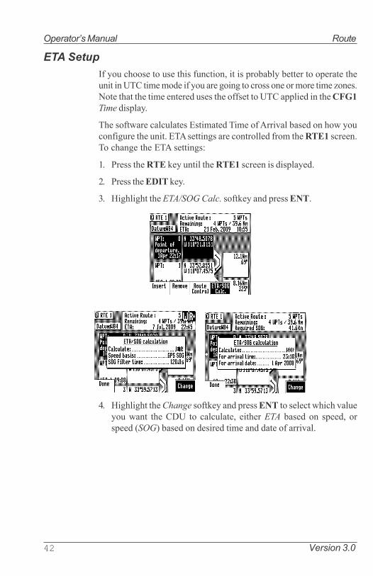
42 Version 3.0
Operator�s Manual Route
ETA Setup
If you choose to use this function, it is probably better to operate theunit in UTC time mode if you are going to cross one or more time zones.Note that the time entered uses the offset to UTC applied in the CFG1
Time display.
The software calculates Estimated Time of Arrival based on how youconfigure the unit. ETA settings are controlled from the RTE1 screen.To change the ETA settings:
1. Press the RTE key until the RTE1 screen is displayed.
2. Press the EDIT key.
3. Highlight the ETA/SOG Calc. softkey and press ENT.
4. Highlight the Change softkey and press ENT to select which valueyou want the CDU to calculate, either ETA based on speed, orspeed (SOG) based on desired time and date of arrival.

Version 3.0 43
Route Operator�s Manual
SOG Based on Arrival Date & Time:
5. Enter the arrival time and date. Be sure to enter the date as day,month, year, as indicated on the screen.
6. Highlight the Done softkey and press ENT.
In this mode, the actual SOG is compared to the required SOG to meetthe specified arrival date and time. The result is given in a percentage(%) value next to the displayed SOG in the NAV screens. If the per-centage is below 100, you will arrive late. If the percentage is above100, you will arrive early.
ETA Based on Speed:
5. Select a Speed Basis of either GPS SOG, which uses a long filtertime (in seconds) that you define, or Constant, which uses a speedyou intend to maintain (you define the speed).
6. Highlight the Done softkey and press ENT.

44 Version 3.0
Operator�s Manual Route
RTE2 - The Route Bank
The Route Bank is a convenient place to pre-program segments of along voyage, or to program routes that you follow repeatedly. Creatingroutes for the Route Bank uses the same methods as the Active Routewith a few exceptions: you can�t use the GOTO key, and you can�t usethe Plotter screen. You can use other routes as a subset to create a newroute. Remember, you can always tie routes together in the ActiveRoute by inserting one after another. You will find a Route Name softkeywhen you first enter the edit mode. The Route Name allows you toclearly identify each route by name, number and symbol when you areviewing the Route Bank from the main menu. To create a route:
1. Select the RTE key until the RTE2 screen is displayed.
2. Move the cursor to the route number you want to create or edit.
3. Press the EDIT key.
4. Use the entry methods described in the Creating a Multi-Waypoint
Active Route section.
If you have a route in RTE1 that is not stored in RTE2, you can copyit into the Route Bank by selecting Insert then Insert Route, eitherin the forward or reverse direction.
5. Highlight the Escape softkey and press ENT.
6. When you are finished adding waypoints, highlight the Route Name
softkey and press ENT.

Version 3.0 45
Route Operator�s Manual
You can enter any name, number or symbol you want this route tobe identified by.
6. Highlight the Done softkey and press ENT when you are finishedediting the name.
Note: It is a good idea at this point to select Lock Route so that way
you don�t accidentally erase the route.
7. Finally press the EDIT key to exit the edit mode.
Note: The RTE1 screen is not active until the antenna is detected.

46 Version 3.0
Operator�s Manual Route
&������
Waypoint
The Waypoint Bank (WPT) is a list of waypoints that you createdusing various methods. The most common method is by manuallyentering Lat/Long coordinates. Another convenient method is byusing the Mark function key to saved your present position.Waypoints can also be downloaded from external waypoint data de-vices, such as plotters or ECDIS.
While entering waypoints in the list is rather straight forward, theMX51x provides helpful waypoint management tools that should bementioned before giving examples.
Below are six methods of managing the waypoint bank:
Ø Sort By Number - displays the waypoints in waypoint numericalorder, starting with waypoint 0.
Note: Waypoint �0� is a computer waypoint. The MX51x auto-
matically loads the present position in this waypoint when
a new destination is selected to go to.
Ø Sort By Name - displays the waypoints by name in alphabeticalorder.
Ø Sort By Type - displays the waypoints by symbols, numbers, thennames.
Ø Sort By Distance - displays the waypoints which are closest toyour present location first.
Ø Sort By Age - displays the waypoints entered most recently, first.
Ø Search For WPT - allows you to type a symbol or name and thescreen displays all waypoints having the exact match of the nameyou type. If you are unsure of the complete name, type a few ofthe characters you know are in the name, and the software willdisplay all waypoints having the corresponding characters.
For example, if you are looking for the LA HARBOR ENTRANCEand you enter HAR, the screen will display all waypoints withthese three characters in this exact order.

Version 3.0 47
Waypoint Operator�s Manual
Creating and Editing Waypoints
When editing a waypoint, you are always prompted to select the ap-
propriate datum. You might occasionally see a prompt warning you
that the waypoint is used either in a stored route or the active route.
You ultimately have the final decision whether to continue editing
the waypoint, or exiting this waypoint by pressing the EDIT key again
to exit the edit mode.
Creating and editing waypoints is easy.
1. Press the WPT key to display the WPT1 screen.
2. Press the EDIT key to bring up the softkey.
3. When the waypoint bank is empty, the softkey �Make New WPT�
is highlighted, press ENT to select it.
4. Scroll left to �Make new WPT� and press ENT to start entering L/L
coordinates for waypoint #1 or if you want to modify an existing
waypoint, highlight the �Edit this WPT� softkey then press ENT.

48 Version 3.0
Operator�s Manual Waypoint
&%���A����8�0
(�%�����0��#B(����6C���������7�����1�2���0B(�
( %��������6C���D�������D���0��#B(���������7�����1�2�����6C
(7%������������8�0 �/���9�����2������3��;�/�����3�����:�2C�����������3�0 ���������7����3��/�����3
����7��9�����9�9��6C:�2C�9��5��4�9�����% ���������7�%
������9�����9����3���9� �����3% ������D��76��2�928�����28%
�%����������22�9����������� ������D��76��2������928�����28%
)%����29�:4�0 ��6C ���������5��2��������� ������D��76��2������928�����28%
"%����29�:4�0 ���������;��4C 2����5��2��������� ������D���2����2:�A�4%

Version 3.0 49
Waypoint Operator�s Manual
4a. Make New WPT - Select Lat/Lon (W84), Lat/Lon Datum, or Range
Bearing.
Lat/Lon (W84) - allows you to enter coordinates in the WGS 84datum. This choice takes you directly into the coordinate inputscreen. Go to step 5.
Lat/Lon Datum - allows you to choose a datum (see the list in thescreen sample above) from the more than 110 available Datums.Highlight the desired datum and highlight the Select softkeythen press ENT. Refer to Appendix A - Datum List for a com-plete list of datums and their WGS-84 offset. Go to step 5.
Range Bearing - allows you to define new waypoint coordinatesfrom an existing waypoint in the Waypoint Bank. When youuse this feature make sure you align the cursor next to the from
waypoint number before you highlight the Make New WPT
softkey and press ENT.
Once you have entered the range and bearing, the CDU calcu-lates the coordinates. You can then enter a text description ormodify the waypoint number as described in step 6 below. Go tostep 6.
4b. Edit This WPT - Select Accept to use the WGS 84 datum or high-light Change and press ENT to choose from the more than 110available Datums. Highlight the desired datum and highlight the

50 Version 3.0
Operator�s Manual Waypoint
Select softkey then press ENT. Refer to Appendix A - Datum List
for a complete list of datums and their WGS 84 offset.
5. Enter the appropriate coordinates using the cursor key and nu-meric keypad.
6. Move the cursor down and modify the waypoint number if youwish. Otherwise the CDU assigns the next available number, begin-ning at 1.
Range & Bearing Lat/Lon
This feature allows you to create a range of waypoints within aparticular area. For example, you could put all of the waypoints forfishing spots near Catalina Island in the range of 500 to 530, all thewaypoints for Cabo San Lucas in the range of 575 to 600, etc.
7. Move the cursor down, and enter the symbol and name informa-tion (optional). Use the techniques described in the EDIT keypad
& Display Description section at the front of this manual.

Version 3.0 51
Waypoint Operator�s Manual
The following international characters are supported by cyclingthrough the standard letter function key:
ABC = Ä, Å, Æ, À, Ç
DEF = É, È
GHI = Í
MNO = Ñ, Ó, Ö
STU = Ú, Ü
Press the CFG key when in the edit mode to cycle through theseadditional characters:
� � $ & ! ( ) ? / + - ° . , :
About one second after you stop scrolling through the alpha char-

52 Version 3.0
Operator�s Manual Waypoint
acters, the cursor will automatically advance to the next space.
7. Highlight the Done softkey and press ENT.
8. When you are finished, highlight the Lock this WPT softkey andpress ENT to avoid accidentally erasing the waypoint in the future.
Note: Locked waypoints can not be overwritten by
waypoints downloaded from the NMEA port or
saved by the Mark or MOB functions.
9. Then press the EDIT function key to end editing.
You can press the EDIT key when you finish editing a waypoint.This is treated the same as highlighting the Done softkey and pressENT. Highlighting Done then press ENT allows you to continueediting and entering other waypoints.
Waypoint Lock/Unlock
Locking a waypoint forces the user to consciously unlock the waypointbefore it can be modified and prevents the waypoint from being over-written when waypoints are being input over the data port. Note thatwhen a waypoint received on the data port has the same waypointnumber as a locked waypoint already stored in the CDU, the waypointdata received on the data port is disregarded and lost. Waypoints arelocked by one of three methods: 1) selecting Lock this WPT when inthe waypoint bank edit mode for a particular waypoint; 2) selectingLock this WPT when in the waypoint bank edit mode; or 3) incorporat-ing a waypoint into a route stored in RTE2 and then locking the route.
Waypoints that are locked from the waypoint bank are indicated by aclosed padlock in the display. Waypoints that are party to a lockedroute will display a message indicating that waypoint can not be modi-fied.

Version 3.0 53
Waypoint Operator�s Manual
To Lock a Waypoint
1. Press the WPT key to display the WPT1 screen.
2. Scroll to the desired waypoint.
3. Press the EDIT key.
4. Highlight the Lock this WPT softkey then press ENT.
5. Press the EDIT key.
To Unlock a Waypoint
1. Press the WPT key.
2. Scroll to the desired waypoint.
3. Press the EDIT key.
4. Highlight the Unlock this WPT softkey then press ENT.
5. Press the EDIT key.
If you simply want to modify the waypoint, Edit this WPT will bedisplayed on the bottom left of the screen.
To Lock all Waypoints
1. Press the WPT key.
2. Scroll to the desired waypoint.

54 Version 3.0
Operator�s Manual Waypoint
3. Press the EDIT key.
4. Highlight the More softkey and press ENT.
5. Highlight the More softkey again and press ENT.
6. Highlight the Lock all WPT softkey and press ENT.
7. Press the EDIT key.
To Unlock all Waypoints
1. Press the WPT key.
2. Scroll to the desired waypoint.
3. Press the EDIT key.
4. Highlight the More softkey and press ENT.
5. Highlight the More softkey again and press ENT.
6. Highlight the Unlock all WPT softkey and press ENT.
7. Press the EDIT key.
Removing Waypoints
Unlocked waypoints can be overwritten manually or by waypointsreceived on the NMEA port. Waypoints that are contained within astored route can not be removed until they are removed from the storedroute in the RTE2 screen. If you try to remove a waypoint stored in aroute, a warning will be displayed indicating the first route a waypointis stored in.

Version 3.0 55
Waypoint Operator�s Manual
If the waypoint you want remove is locked, refer to the Waypoint
Lock/Unlock section for a step by step procedure, and then return tothis section.
To remove a waypoint:
1. Press the WPT key.
2. Scroll to the desired waypoint.
3. Press the EDIT key.
4. Highlight the Remove softkey then press ENT.
There are three methods to remove a waypoint: Remove this WPT,Remove Unused, and Remove Range:
5a. If you select Remove this WPT, the waypoint will immediately beremoved from the Waypoint bank.
5b. If you select Remove Unused, the CDU will delete all waypointsthat are not locked or stored in a route. You will be prompted toconfirm the deletion:
5c If you select Remove Range, the CDU will delete all unlockedwaypoints that are not stored in a route between a range ofwaypoint numbers that you enter. You will be prompted to con-firm the deletion:

56 Version 3.0
Operator�s Manual Waypoint
6. Press the EDIT key.
Moving waypoints
This feature allows you to create a range of waypoints within a par-ticular area. For example, you could put all of the waypoints for fishingspots near Catalina Island in the range of 500 to 530, all the waypointsfor Cabo San Lucas in the range of 575 to 600, etc.
To move a waypoint or range of waypoints:
1. Press the WPT key.
2. Press the EDIT key.
3. Highlight the More softkey then press ENT.
4. Highlight the Move softkey then press ENT.
5a. To move a single waypoint, enter the original waypoint number onthe First WPT Number and Last WPT Number.
5b. To move a range of waypoints, enter the first and last waypointnumbers to move on the First WPT Number and Last WPT Number.Keep in mind that the CDU will sort these waypoints numericallyand all waypoints between the entered numbers will be moved tothe new location.

Version 3.0 57
Waypoint Operator�s Manual
6. Enter the waypoint number where you want the first waypoint movedto in Destination WPT Number.
If the destination waypoint number is already being used, you willbe prompted to either overwrite the first waypoint (Yes) and eachsubsequent waypoint that is to be overwritten, confirming eachwaypoint one at a time, overwrite all the waypoints (Yes To All), notoverwrite any waypoints (No); or Escape back to base softkeymenu. Don�t forget to press the EDIT key to exit.
Saving or Restoring Memory Data Using a USB Device
The MX51x is equipped with two sealed USB connectors, one in frontand one in the back of the unit. They can be used to convenientlysave or restore navigation data such as waypoints, routes, plot tracksand configuration settings using a USB memory stick.
Note: It is important that the USB stick be formatted first to Win-
dows FAT 32 before using it with the MX51x. The USB formatting
procedure is available in Appendix G of this manual.
To store memory data in the USB device, do the following:
1. Insert the USB device in the MX51x.2. Press the CFG key.3. Scroll down to USB menu.

58 Version 3.0
Operator�s Manual Waypoint
4. Press the EDIT key.5. The Change softkey is highlighted at this point, press ENT key.
6. Wait for the MX51x to recognize the USB device before proceed-ing. It will indicate the device type, status and memory spaceavailable when it is done checking the USB device.
7. Highlight �Data type� then press ENT to change to Waypoints,Routes, Plot, Config or All. Using �All� will save everything.
8. Highlight Save to USB softkey then press ENT. It will take a fewseconds to save the data. The MX51x will tell you when theprocess has been completed.
9. Press the ENT to continue.10. Before removing the USB, set the USB connected to NO. This is
important to prevent causing damage to the USB device or thedata in it.

Version 3.0 59
Waypoint Operator�s Manual
To restore memory data from the USB device to the MX51x, do thefollowing:
1. Insert the USB device in the MX51x.2. Press the CFG key.3. Scroll down to USB menu.4. Press the EDIT key.5. The Change softkey is highlighted at this point, press ENT key.6. Wait for the MX51x to recognize the USB device before proceed-
ing.7. Highlight �Data type� then press ENT to change to either
Waypoints, Route, Plot, Config or All. Using �All� will restoreeverything.
8. Highlight Restore softkey then press ENT.
9. It will pop-out a dialog window asking if this is what you want todo. Answer YES (0r NO) by pressing the ENT key (or scroll toNO if you are not sure and press the ENT key).
10. Depending on th amount of data, it may take 5 to 10 seconds orlonger to complete this action. The display will advise you whenit is done restoring.
11. Before removing the USB, set the USB connected to NO. This isimportant to prevent causing damage to the USB device or to the
data in it.

60 Version 3.0
Operator�s Manual Waypoint
Downloading Waypoints & Routes to Other Devices
The MX51x can download all stored waypoints, routes and configura-tion settings to other NMEA 0183 compatible devices which acceptthe WPL, RTE, and Rnn data sentences. These sentences are con-trolled in the CFG1 screen NMEA Out (1 or 2) for the identifier givenbelow.
The CDU outputs these sentences in the following format:
Rnn - Routes:
Waypoint identifiers, listed in order with starting waypoint first, forroute number �nn�. The active route in the CDU is always route zero,but in the Rnn sentence the route number can be transmitted as eitherroute 00 or 01.
Rnn is NMEA version 1.5. Use of GPRTE is recommended to complywith NMEA version 2.1.
field#: 1 2 3 4 1 1 1
4 5 6 $GPRnn,cccc,cccc,cccc,.....,cccc,cccc*hh<CR><LF>
explanation / actual use:
1: nn = active route number, 00 or 01can be set to 00 or 01 (default 00).
2 - 15: 14 field sequence of route waypoint IDs.
16: Checksum can be set on or off (default on).
RTE - Active Route:
Waypoint identifiers, listed in order with starting waypoint first, forthe identified route. Two modes of transmission are provided: �c� indi-cates that the complete list of waypoints in the route are being trans-mitted; �w� indicates a working route (active) where the first listed

Version 3.0 61
Waypoint Operator�s Manual
waypoint is always the last waypoint that has been reached (FROM),while the second listed waypoint is always the waypoint that you arecurrently heading toward (TO). The remaining list of waypoints repre-sents the remainder of the route.
RTE can be sent as version 2.1 and 2.0.
field#: 2 3 4 5 6 1 1 1
5 6 7
$GPRTE,x,x,a,cccc,cccc,.....,cccc,cccc*hh<CR><LF>
explanation / actual use:
2: Total number of messages being transmitted (a single routemay require the transmission of multiple messages). A maxi-mum of 11 waypoints are transmitted in each messages.
3: Message number.
4: Message mode: c = complete route, all waypoints, w = work-ing , 1st listed waypoint is �FROM�, 2nd is �TO� and remainingare the rest. c/w can be set to c or w (default w).
5: Route identifier, always 00 (Active Route only).
6 - 16: Waypoint identifiers, (less than 11 waypoints may be in themessage).
The number of remaining waypoints can be set to 1, 2 or �all�(default all) shortening the drawn track on the plotter.
17: Checksum can be set on or off (default on).
WPL - Waypoint Location - NMEA 0183 Standard:
Latitude and Longitude of specified waypoint. The content of thissentence will normally be the position of the next waypoint in theroute.
The CFG1 NMEA out WPL has a special �Send All� option. Selectingthis feature will send all the waypoints in the Waypoint Bank once,independent of the WPL sentence setup as ON or OFF. This formatconforms to the NMEA 0183 standard.
WPL can be sent as version 1.5, 2.0 or 2.1.
field#: 2 3 4 5 6 7
$GPWPL,llll.ll,a,yyyyy.yy,a,cccc*hh <CR><LF>

62 Version 3.0
Operator�s Manual Waypoint
explanation / actual use:
2 & 3: Waypoint Latitude, North or South, N/S number of decimalscan be set to 2, 3, 4 or 5 (default 2).
4 & 5: Waypoint longitude, East or West, E/W number of decimalscan be set to 2, 3, 4 or 5 (default 2).
6: Waypoint identifier.
7: Checksum can be set on or off (default on).The WPL record can also contain the description information whenInclude Waypoint Names in the CFG1 NMEA, Details is selected.
WPL - Waypoint with Symbols & Description - NMEA 0183 Expanded:
Latitude and Longitude of specified waypoint. The content of thissentence will normally be the position of the next waypoint in theroute.
The CFG1 NMEA out WPL has a special �Send All� option. Selectingthis feature will send all the waypoints in the Waypoint Bank onceindependent of the WPL sentence setup as ON or OFF. This formatdoes not strictly conform to the NMEA 0183 standard, and may notwork with all equipment. It is provided for your use to store data on aPC using normal ASCII text editors.
WPL can be sent as version 1.5, 2.0 or 2.1.
field#: 2 3 4 5 6 7
$GPWPL,llll.ll,a,yyyyy.yy,a,cccc xxxxxxxxxxzzzzzzzzzz*hh
<CR><LF>
explanation / actual use:
2 & 3: Waypoint Latitude, North or South, N/S number of deci-mals can be set to 2, 3, 4 or 5 (default 2).
4 & 5: Waypoint longitude, East or West, E/W number of decimalscan be set to 2, 3, 4 or 5 (default 2).
6. Waypoint identifier; 4 place numeric waypoint number, fol-lowed by 1 space, followed by 10 characters for the top line ofthe description, followed by 10 characters for the bottom lineof the description. When this field is output, you may seespaces between the xxx and zzz. These are �fill characters�

Version 3.0 63
Waypoint Operator�s Manual
and are necessary to fulfill the 10 character count to maintaincharacter placement when read back into the CDU.
7: Checksum can be set on or off (default is on).
Downloading Waypoints to a Personal Computer
You can use any terminal or communications program to download orupload waypoints and routes to or from the CDU and a PC.
Set the PC to:
4800 baud 8 bits1 stop bit no parityno flow control
When sending data to the CDU, it must be sent in block form, followedby (with an appended) CR (carriage return) and LF (line feed). Normalcommunications programs, like Windows 3.1 or 3.11 Terminal are suf-ficient to get the job done. Unfortunately, Hyperterminal in Windows
95 doesn�t provide as simple a terminal emulation program as Win-
dows 3.11, and we have found it unreliable. We suggest that a thirdparty terminal program be used with Windows 95 (or higher).
Using Windows Terminal, do the following (from the Program Man-
ager):
1. Connect the CDU�s port (1or 2) to the PC�s communications port(Refer to the Appendix G of this manual).
2. On the CDU press the CFG key.
3. Scroll down the menu to NMEA Out 1 (or which ever port number
is required).
4. Press the EDIT key.
5. If the port is already Active (Yes), write down which NMEA sen-tences are set to Yes, then set all of the NMEA sentences to No.You need to do this to record just the waypoint data.
If the port is not Active (No), change it to Yes.
6. Scroll down to the WPL record and change it On.
7. Highlight the Details softkey and press ENT.

64 Version 3.0
Operator�s Manual Waypoint
8. Set Include Waypoint Names to either No or Yes. Refer to WPL -
Waypoint Location - NMEA Compliant and WPL - Waypoint With
Symbols & Description - NMEA 0183 Non-Compliant sections inthis manual to determine the correct format for your purpose.
9. Set Decimals in Position to 4.
10. Highlight the Done softkey and press ENT.
11. Set the WPL record to Off (you will need to turn the data off whilesetting up the computer).
12. On the computer, double click on the Accessories icon.
13. Double click on the Terminal icon.
14. Click on the Settings menu.
15. Double click on the Communications menu item and make the fol-lowing settings:
4800 baud8 data bits1 stop bitParity - noneFlow Control - noneConnector - Com1 (or Com2, depending where the externalinterface is)Parity Check - blankCarrier Detect - blankOK
16. Click on the Transfers menu.
17. Double click on the CDU Text File menu item and make the follow-ing settings.[give the file a name.txt][select a location (folder) to store the file]OK
18. On the CDU, you should still be in edit mode on CFG1 NMEA Out
1 with the cursor flashing on Off at the WPL record. Press the Send
All softkey.
19. When all the waypoint sentences are sent, click on the Stop buttonon the PC.
20. Press the EDIT key on the CDU to exit the edit mode.

Version 3.0 65
Waypoint Operator�s Manual
Uploading Waypoints from Other Devices
The CDU will accept waypoints from any device which follows theWPL formats identified earlier in the Waypoint section. The first twocharacters following the $ can be any NMEA defined talker ID. You donot have to calculate and include the checksum; however, you mustend each data record with a carriage return and line feed. If you doinclude the checksum at the end of the data record, the CDU will verifythe checksum. If the checksum is invalid, the waypoint will be rejected.
Waypoints received on the data port will be stored to the waypointlocation specified in the WPL record. If the waypoint location speci-fied in the WPL record is already occupied, the CDU will overwrite theexisting waypoint (if it is unlocked). If the existing waypoint is locked,the WPL record received on the input port will be ignored and dropped.
The CDU will only recognize waypoints from one input port at anygiven time. This port is defined in CFG1 => WPT & RTE In.
Uploading Waypoints from a Personal Computer
You can use any terminal or communications program to download orupload waypoints and routes to or from the CDU and a PC.
Set the PC to:
4800 baud8 bits1 stop bitno parityno flow control
When sending data to the CDU, it must be sent in block form, followedby (with an appended) CR (carriage return) and LF (line feed). Normalcommunications programs, like Windows 3.1 or 3.11 Terminal are suf-ficient to get the job done. Unfortunately Windows 95 and new Win-

66 Version 3.0
Operator�s Manual Mark or Event
dows O/S doesn�t provide a basic terminal emulation program; there-fore, a third party program is required with Windows 95 and above.
Using Windows Terminal, do the following (from the Program Man-
ager):
1. Using an RS-232 to RS-422 convertor, connect the CDU�s port 1 or2 to the PC�s communications port.
2. On the CDU press the CFG key until CFG1 screen is displayed.
3. Scroll down the menu to WPL Input.
4. Press the EDIT key.
5. Set the Transducer Connected to Yes.
6. Set the Data Input Port No. to 2.
7. Press the EDIT key.
8. On the computer, double click on the Accessories icon.
9. Double click on the Terminal icon.
10. Click on the Settings menu.
11. Double click on the Communications menu item and make the fol-lowing settings:
4800 baud8 data bits1 stop bitParity - noneFlow Control - noneConnector - Com1 (or Com2, depending where the externalinterface is)Parity Check - blankCarrier Detect - blankOK
12. Click on the Transfers menu.
13. Double click on the Send Text File menu item and make the follow-ing settings:
[select the correct file name.txt][select the correct location (folder) for the file]check the Append LF boxOK

Version 3.0 67
GOTO Operator�s Manual
14. When all the waypoint sentences are sent, press the WPT key andscroll through the list to ensure all the waypoints transferred prop-erly.

68 Version 3.0
Operator�s Manual GOTO
Mark / MOB
This is a dual function key that either stores your present position,date and time at the next available waypoint location in the WaypointBank or when pressed continuously for 3 seconds, calculates a MOBrange and bearing to a saved spot (See MOB section on page 80). Awindow pops up on the screen to confirm your key depression, and totell you where the Mark position is being stored. You can go into theWPT menu and edit the coordinates or description later. This keyfunction is disabled for 2 seconds after each depression.
The cross-hair (⊕) symbol to the left of the date in the Waypoint Bankindicates that the Mark or Event key created this waypoint. Note thatyou can also select the cross-hair (⊕) symbol from the various sym-bols for other waypoints when editing waypoints.
The CDU is also capable of performing this function from a remotecontact closure input via the AUX Cable �MOB/Event� wire. Refer tothe Appendix G of this manual for interface instructions. Contact clo-sure on the two input pins for less than 2 seconds causes a Markposition to be generated. Contact closure on the two input pins forlonger than 2 seconds causes a Man Over Board condition to be gen-erated.
Note: The marker stores the position of the antenna loca-
tion. Keep this in mind if you are trying to pinpoint items
such as buoys, crab pots, etc. For some special appli-
cations such as these, you may need to locate the an-
tenna at the point on the boat or ship where you need to
make this exact measurement.

Version 3.0 69
GOTO Operator�s Manual
��$�$��,
GOTO
Using the GOTO function key is the fastest way to create a single legroute. This method will cause the existing active route to be erased andoverwritten with the new position you define.
1. From any screen press the GOTO key.
2. Press the EDIT key.
3. Select the waypoint determination method you want:
Waypoint Number - allows you to choose a waypoint stored in theWaypoint Bank, where you enter the waypoint number.
Choose in Bank - as used in the Route function (refer to Route -
Choose In Bank section of the manual), allows you to viewwaypoints in the Waypoint Bank as a list.
Lat. Lon., UTM- allows you to define a coordinate and description,which is also stored at the next available waypoint location inthe Waypoint Bank.
Bearing Range - allows you to define a coordinate by specifyingthe bearing and range from your present position, which is alsostored at the next available waypoint location in the WaypointBank.
If you make a mistake, you can use the cursor key to position thecursor over the mistake and overwrite the error.
Use the DGPS key or cursor key to insert a space in the descrip-tion, if needed.
Use the CFG key to select a special character, if needed.
4. To activate the GOTO waypoint, press the EDIT key. A warning isbriefly displayed indicating that the active route will be replacedwith the GOTO route.
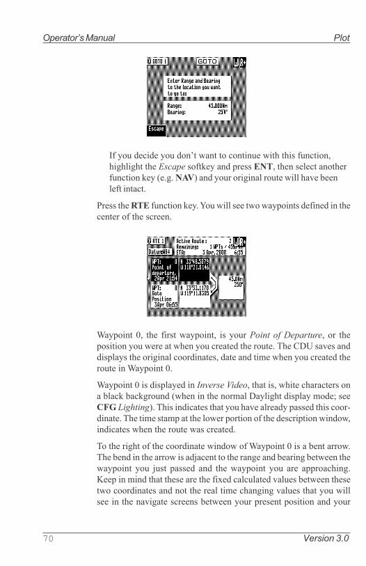
70 Version 3.0
Operator�s Manual Plot
If you decide you don�t want to continue with this function,highlight the Escape softkey and press ENT, then select anotherfunction key (e.g. NAV) and your original route will have beenleft intact.
Press the RTE function key. You will see two waypoints defined in thecenter of the screen.
Waypoint 0, the first waypoint, is your Point of Departure, or theposition you were at when you created the route. The CDU saves anddisplays the original coordinates, date and time when you created theroute in Waypoint 0.
Waypoint 0 is displayed in Inverse Video, that is, white characters ona black background (when in the normal Daylight display mode; seeCFG Lighting). This indicates that you have already passed this coor-dinate. The time stamp at the lower portion of the description window,indicates when the route was created.
To the right of the coordinate window of Waypoint 0 is a bent arrow.The bend in the arrow is adjacent to the range and bearing between thewaypoint you just passed and the waypoint you are approaching.Keep in mind that these are the fixed calculated values between thesetwo coordinates and not the real time changing values that you willsee in the navigate screens between your present position and your

Version 3.0 71
Plot Operator�s Manual
next waypoint during normal navigation.
Below Waypoint 0 is the waypoint you defined in the GOTO function.Notice that this information is in standard video, black characters on awhite background, and that an ETA time is displayed in the same posi-tion as the waypoint passed time in Waypoint 0. This indicates thatthe waypoint has not been passed yet. Remember that the ETA time isfiltered over time, so allow a few minutes for the filter to settle whenyou first get underway or make course and speed changes.
72 Version 3.0
Operator�s Manual Plot
(�#$�%&#
Plot
The PLOT1 screen displays graphic information around the boat atyour present position. The boat always remains in the center of thescreen.
If you define some of your navigation markers in the Waypoint Bankwith a symbol in the first character position, the navigation symbol willshow up in relation to your planned course on the plot screen, just asit does in the NAV1 Panorama screen. In addition to the graphic de-tails provided by the CDU, the Plot screens provide basic navigationinformation, zoom-in/out capability and scaling factors for the displayfrom around 10 to 20 meters, depending on your latitude, out to 128nautical miles. You will find these feature very helpful in many ways,and we will provide you with a couple of ideas on how to make gooduse of the PLOT function after the screen description which follows.
Note: The Plot screens do not show your route and cross-track
error lines when in Great Circle Navigation mode.
The following CFG menus directly impact the PLOT functions:
Ø Navigation - sets a variety of important functions and alarms.
ð Rhumb Line or Great Circle navigation
ð Range units: nautical miles, nautical miles and meters (whenunder 1,000 meters), nautical miles and feet (when under 1,000feet), statute miles, statute miles and meters (when under 1,000meters), statute miles and feet (when under 1,000 feet), kilome-ters, or kilometers and meters (when under 1,000 meters)
ð Waypoint Pass Criterion and distance
ð Waypoint Approach distance
ð Autopilot alarm control
ð Cross-track error limits
Ø COG / SOG Filter Settings.
Take a quick look at both screens. They both have a graphical area tothe right, and a text data area to the left.

Version 3.0 73
Plot Operator�s Manual
In the PLOT screens the UP arrow key is the Zoom-out key; the DOWN
arrow key is the Zoom-In key. Each time you depress one of thesearrow keys, you scale by one-half or by double the graphical area. Ifyou look to the top of the screen, just right of the page number, youwill see a number in a white square. This is the scale of the graphicwindow based on the units selected in CFG1 Navigation. Now lookalong the left and right edge of the graphic window, you will see somevertical black and white dash marks (these are harder to see at smallscales like 1 and 2 or at large values such as 64 or 128). Each solid dashmark represents 1 nautical mile. A broken dash mark indicates 1/100thof a nautical mile when you are zoomed in at low scale. You will findyour bearing and range to the next waypoint.
The CFG1 Navigation menu allows you to display fractions of themajor unit (nautical miles, statute miles, or kilometers) ranges less than1000 in alternate units of feet or meters.
PLOT 1 - Relative to Boat
The information in PLOT1 is always relative to your present position.The boat always remains in the center of the screen and the bearingand range are always from your present position to the next waypointidentified in RTE1.

74 Version 3.0
Operator�s Manual Plot
Customizing the Display
There are a number of display options available, press the EDIT key tomodify the screen to your needs.
Highlight the Display Options softkey and press the ENT key.
The following choices are available:
Ø Show Boat - Yes is the default condition, which places the boaticon in the middle of the screen. No places the boat in a CompassRose in the upper right corner of the screen (see the diagram be-low), where your direction is indicated by the boat in the CompassRose. The boat�s position is then indicated by an X in the center ofthe screen.
Ø Show All Waypoints - Yes is the default condition, which displaysall waypoints, where the first character of the description is a sym-bol, in its proper location relative to the boat�s position. No causesnone of the waypoints to be displayed.
Ø Show Active Route - Yes is the default condition, which causes theactive route (course lines) and its waypoint symbols to be dis-played. No causes the course lines not to be displayed. Note thatthese lines can only be displayed in Rhumb Line navigation mode(see CFG1 Navigation).
Ø Show Recorded Track - Yes is the default condition, which causesthe course you have already traveled to be displayed. No causesthe traveled course not to be displayed.

Version 3.0 75
Plot Operator�s Manual
Ø Show Off Track Limit - Yes is the default condition, which causesthe active route cross-track error lines to be displayed. These areonly displayed for the leg of the course you are presently on. If youreset your cross-track error, these lines are redrawn to reflect thecourse change (see NAV2). No causes the cross-track error linesnot to be displayed. Note that these lines can only be displayed inRhumb Line navigation mode (see CFG1 Navigation).
Ø Show Lat/Lon Grid - No is the default condition, which causes thecoordinate grid not to be displayed. Yes causes the Lat/Lon grid tobe displayed (regardless of positioning reference system selectionin CFG1 Position). Note that the grid is only displayed at the 4 Nmscale or lower.
Ø Automatic Zoom - No is the default condition, which causes thedisplayed scale to be controlled by you. Yes causes the boat iconto be placed along one edge of the screen and the next waypointflag to be placed along the opposite edge of the screen. As youapproach your waypoint, the screen will automatically zoom in onyour course, then expand back out after you pass the waypointand start the next leg of your course.
If you highlight the Return softkey and press ENT, then highlight theTrack Plotter softkey and press ENT, you will access the recordedtrack options.

76 Version 3.0
Operator�s Manual Plot
Selecting Erase Track then pressing the ENT key allows you to clearyour recorded track. You can keep a portion, say the last mile or two, ofyour recorded track if you like, by specifying the range after you high-light the Erase Track softkey and press ENT. Highlight Erase Now
and press ENT to confirm your action. Highlight Escape and pressENT to return the previous screen without erasing or EDIT to abortthis process.
Selecting Record Track then pressing ENT allows you to define howyour course is saved. Choosing not to save your track may free theprocessor up to run other functions a little bit faster; however, you arenot likely to notice any difference in performance unless all data portsare near their full throughput capacity. You also have three differentlevels of track saving capability: Normal, Fine, and Detailed. Thesoftware saves each calculated position coordinate to draw the linesfor the plot screen. There are a finite number of plot points which cansaved in memory, before the CDU begins overwriting the first set ofplot points. If you are traveling a long distance at a high rate of speed(say over 10 knots) you probably will want to use the Normal selec-tion, which only stores a plot point when your direction changes. Ifyou are doing some tight maneuvering or station keeping tasks, youwill probably want to use the Detailed selection, which stores a posi-

Version 3.0 77
Plot Operator�s Manual
tion every 0.5 meters. The Fine selection stores a plot point every 7meters.
Plot Screen Use Examples
Station Keeping
There may be a time when you want to maintain your position at agiven location in open water. Some applications for this need may be:
Ø Staying over a dive wreck.
Ø Staying over a fishing hole.
Ø Recovering an oceanographic survey point.
If you are placing and recovering crab pots along a course line, youcan enter your course in the RTE1 screen, then place the marker ateach crab pot in turn.
You can also select WPT Pass Criterion: Distance to WPT in the CFG1
Navigation screen and set the WPT Pass Distance: 0.00; or set theWPT Pass Criterion to Manual.
By doing this and putting the coordinate you want to maintain in theRTE1 screen, you will always get the bearing and distance to thewaypoint in the PLOT1 and NAV screens, regardless of your angle ofapproach. Note for the plot example above, we turned off the cross-

78 Version 3.0
Operator�s Manual Plot
track error lines, the active route, and track saving to keep the screenfrom getting cluttered while drifting.
Grid Search
If you are attempting to search a given area, you can use the PLOT1
screen to view your progress and help maintain your proper separa-tion. You can also use the RTE1 screen�s Insert New WPT feature inconjunction with the CFG1 Navigation, WPT Pass Criterion: Dis-
tance to WPT (set the WPT Pass Distance: to the smallest acceptablevalue) to create the search pattern you want to follow. In the RTE1
screen, highlight Insert New WPT and press ENT to define the coordi-nates of the first waypoint. Then use the Insert New WPT softkey todefine subsequent range and bearing coordinates from your originalposition. This technique allows you to quickly define your searchpattern, control the pattern separation, and view your progress alongthe way. The CDU will prompt you to turn at the predeterminedwaypoints you defined. This allows you to pay more attention to thetask at hand, rather than having to keep a close eye on the GPS re-ceiver.
Note: The PLOT screen is not active until the antenna is detected.

Version 3.0 79
Man Over Board Operator�s Manual
Man Over Board
The Man Over Board function key shares the same key with the �Mark
or Event� function key. When depressed for 3 seconds, it activates anumber of automatic functions described below.
Most obviously, it brings up an MOB1 (Plot) screen. This is an auto-matic scaling screen. The screen centers on half the distance betweenyour present position and the MOB position. In addition, the MOBposition is displayed in the upper left corner, so that you can quicklyread the coordinates to others who may be available to render assis-tance. This plot screen also provides the vital bearing and distanceback to the MOB position, as well as your present course over ground.
The MOB position, date and time are stored in the next vacant waypointmemory of the Waypoint Bank for future reference (e.g. log book en-tries). An MOB symbol is used to denote an MOB waypoint.
Note: The range and bearing in the PLOT, NAV,
and MOB screens reflect your bearing and
range back to the MOB position, not the
active route.
NMEA 0183 sentences (i.e. BWC and BWR) and the printer output are

80 Version 3.0
Operator�s Manual Man Over Board
changed to reflect the current situation by also indicating the bearingand range back to the MOB position. This way, other interfaced equip-ment can also help guide you back to the MOB position. When theMOB condition is canceled, the NMEA sentences will automaticallyrevert to the active route information. Don�t forget to cancel the MOB
so your interfaced equipment will read the correct data!
The MOB function key and remote MOB input are disabled from sub-sequent activation until Cancel MOB is selected.
Other functions such as Position and Navigate can still be accessed;however, the screen will revert to the MOB Plot screen after 30 sec-onds.
To cancel an MOB condition, make sure you are in the MOB Plotscreen. Press the EDIT key, then highlight the Cancel MOB softkeyand press ENT. Press EDIT again to exit the edit mode.
Remote MOB
The MX51x is capable of performing the MOB function from a remotecontact closure input via the AUX (8-pin) cable. If the contact closureis made for 3 seconds, the input is registered as a MOB Position. Referto the Appendix G of this manual for wiring interface instructions.

Version 3.0 81
Man Over Board Operator�s Manual
)��- *
Auxiliary
There are eight Auxiliary screens described in this section:
AUX1 - Alarm Log
AUX2 - Speed Graph
AUX4 - Sun Almanac
AUX5 - Moon Phases
AUX6 - Batteries
AUX7 - Unit Information
AUX10 - Current Tide Display
AUX11 - Tide Table Port List
AUX1 - Alarm Log
All alarms are registered in this screen, whether or not they have beencorrected, until the log is erased or the log is full. When the log is full,the oldest alarms are overwritten. Alarms with an asterisk (*) next tothe alarm number have not been corrected and can not be reset untilthey are corrected.
Reset Log clears the alarm log entries, except for any alarm conditions which havenot been corrected and any alarms which have occurred since the uncorrectedalarm.

82 Version 3.0
Operator�s Manual Auxiliary
AUX2 - Speed Graph
The graph scales automatically to the speed you are at. You can zoomout to the last 56 minutes or in to the last 3.5 minutes. It is a handy toolif you are trying to maintain a certain speed.
AUX3 - Not Used
AUX4 - Sun Almanac
This almanac provides the sunrise and sunset times for a given dayand location. You can enter another date or location of interest bypressing the EDIT key, and editing the appropriate date and/or place.

Version 3.0 83
Auxiliary Operator�s Manual
AUX5 - Moon Phases
There are no edit functions available here. Moon phases are given inapproximately one week increments and include all dates for new, half,and full moon. You change the year displayed by pressing the up ordown cursor keys.
AUX6 - Batteries
This display is where you reset the Lithium battery age. Press theEDIT key and highlight the Reset Age softkey then press ENT afteryou replace the Lithium battery. Refer to the Appendix G of this manualfor instructions on replacing the memory backup battery. This batteryhas a normal life of about 2 years.

84 Version 3.0
Operator�s Manual Auxiliary
AUX7 -Unit Information
This screen indicates the specific CDU model, software version num-ber, the hardware configuration, and the printed circuit board (PCB)serial number of your CDU. If you are having problems with yourCDU, refer to this screen for information to provide to customer ser-vice personnel.
A special softkey sequence displays sub-version levels, the actualsoftware build date and time, and allows access to a selftest sequence.This information is useful to the technician and our Field Engineersduring troubleshooting. To activate the screen press the EDIT key,then press the �1� or �NAV� key three (3) times. Additional informationin the Software window will be displayed.
MX510 AUX7 Screens
MX512 AUX7 Screen
This also activates several engineering screens (the same as turningEngineering Display to Yes in CFG1 Operation). Refer to Appendix C
- Engineering Mode for more details.

Version 3.0 85
Auxiliary Operator�s Manual
AUX 10 - Tide
There are two TIDE screens, which are located under the AUX option.The AUX 10 screen displays graphic and digital information about thetide conditions at your present position. This is based on tide tableconstants that you must enter in the AUX 11 screen, then accessthrough the AUX 10 screen. You can store up to 100 tide tables inAUX 11.
The following CFG1 menus directly impact the TIDE functions:
Ø Depth - sets the measurement units in meters, feet, or fathoms.
Note: The Tide function is not active until the antenna is de-
tected.
Current Tide Display
This screen provides the current tide conditions for the tide constantsindicated in the upper left hand corner. The number in the upper leftcorner of the window is the identification number of this table in theBritish Admiralty Tide Table and in the AUX 11 screen. The name tothe right of this number is the port name you entered in the AUX 11
screen.
A graphical representation of the tide is given in the middle of thescreen. The tide peak references are given to the right of the High/Lowtime on the right of the screen. High/Low tide times are given to theright of the graph. The marker time (indicated by the clock icon or +sign in the graphic area) and tide condition are given below the High/Low tide information.
The tide marker automatically updates to the current time. When thetide marker is in the automatic mode, the cross-hair indicator is en-closed with a circle . You can move the marker forward or backward intime using the up or down arrow keys. Return the marker to the presenttime by simply highlighting the Marker to Now softkey then pressing

86 Version 3.0
Operator�s Manual Tide
the ENT key. When you move the tide marker off of the present time,the marker changes to a + sign. The marker will remain at the manuallypositioned mark until you either select one of the manual marker con-trol softkeys, or until you highlight the Marker to Now softkey andpress ENT - which returns the marker to automatic mode.
The tide measurement units can be displayed in meters, feet, or fath-oms. Tide units are controlled along with depth units in the CFG1
Depth screen.
To select another port�s tide table, press the EDIT function key, anduse the Change softkey to scroll down the list or the Go Back softkeyto scroll up the list.
While in the edit mode, you can also move the cursor down to the dateand manually change it to any date you are interested in.
Once you have found the table you need, press the EDIT key again toload the table.
AUX 11 - Tide Table Port List
AUX 11 is where you store the constants for the port tide tables youare interested in. You can store up to 100 tide tables. You can purchasethe Admiralty Tide Table Part III book from:
Admiralty Tide Tables and Tidal Stream TablesPublished by the Hydrographer of the Navy,United Kingdom
Hydrographic OfficeTauton, Somerset TA1 2DNUnited Kingdom
+44-1823-337-900+44-1823-323-753 Fax46274 Telex

Version 3.0 87
Auxiliary Operator�s Manual
This is a three volume set of tide tables, divided as follows:
�2�6C���
�2�6C��&
�2�6C��&
�2�6C��!
)&!!#$��%)$$
The display provides the required tide table document name and sec-tion (Admiralty Tide Tables, Part III) under the Help softkey when inthe edit mode as an added aid to help you identify the proper referencematerial.
Information about the Admiralty Tide Tables port lists and other pub-lications and where they can be purchased is available from the officialAdmiralty Chart and Publications website at www.ukho.gov.uk.
You may also contact us by fax, e-mail, or phone number provided atthe back of this manual if you need information on how to get a copyof the tide table list.

88 Version 3.0
Operator�s Manual Auxiliary
Adding a Port
To add a port to the list, first locate it in Part III of the tide table book,then align the cursor with Add port to the Port List and press EDIT.The Zone in the upper left corner refers to the time zone offset to UTC.Use the name given in the tide table for the name given in the Place
portion of the screen. To help you locate this port in the printed vol-ume later, use the table number given in the first column of the manualas the tide number in the CDU.
Then simply follow along the table in the manual and enter the appro-priate offsets. The software is setup just like the manual. You mayencounter a table that requires seasonal offsets. Where these mightapply, the CDU provides you the opportunity to input a Fixed value orthe seasonal Table values. Highlight the first softkey and press ENT
to toggle between these two selections. Highlight the second softkey,Edit Table, and press ENT to make the necessary corrections. High-light the Done softkey and press ENT when you finish the seasonaltable, otherwise press the EDIT key when the necessary data is en-tered.
You can scroll through the entered tables with the up and down cursorkeys when you are not in the edit mode. You also have the option tomodify or delete a port from the list.
Tide table information is mapped to an area of RAM which is saved
during future software upgrades.
Version 3.0 89
Tide Operator�s Manual
Position
There are three POS screens in the CDU. The POS functions arehighly interactive with a number of CFG1 menu selections.
The following CFG1 menus directly impact the POS functions:
Ø COG SOG - sets the filtering time for the displayed values.
Ø Datum - sets the reference datum for your present position.
Ø DGPS - sets the internal or external control for RTCM SC-104 cor-rections which affect your position accuracy.
Ø GPS - sets an offset for calculating the GPS antenna position if youcan�t physically locate the antenna exactly where you want it (i.e.over the centerline of the boat); sets the minimum elevation angleto look for satellites; and in 6 channel models, it also controls thesatellite selection process.
Ø Navigation - sets a variety of important functions and alarms (usedin other function screens), but only the Range units:
nautical miles (Nm)nautical miles and meters (Nm/mtrs)nautical miles and feet (Nm/ft)statute miles (Sm)statute miles and meters (Sm/mtrs)statute miles and feet (Sm/ft)kilometers (Km), orkilometers and meters (Km/mtrs), affect the POS screens.
Ø Position - sets Lat/Lon or UTM, Grid (optional) and some alarmlimits.
Ø Time - sets appropriate offsets, and 12 or 24 hour clock mode.
POS1 - Position Display (Large Lat/Long Digits)
This display provides the largest presentation of the Lat/Long coordi-nates from the CDU. In addition to the coordinates and datum in use,it also displays the current course (COG) and speed (SOG) over ground.There are no edit functions available in this screen unless it is in Dem-
onstration mode. Refer to Appendix E - Demonstration Mode for a fulldescription of this feature.

90 Version 3.0
Operator�s Manual Tide
Latitude & Longitude
UTM
When using the UTM reference system in the polar regions of theEarth, the CDU displays position using the UPS coordinate systeminstead of invalid UTM coordinates.
User GRID
User defined grids is an optional feature of the MX51x. When enabledyou can set the receiver to provide Easting and Northing position databased on a local grid. The grid function is set up in the CFG1 Position
screen. A special license is required to activate this special feature.
POS2 - Position, Altitude, Magnetic Variation, & Time
This screen is divided into three windows. The upper left windowprovides your position coordinates, the antenna altitude (above MeanSea Level - MSL), altitude mode (2D or 3D), the magnetic variation(Variation) for your present position, and the present datum in use forcalculating your position.
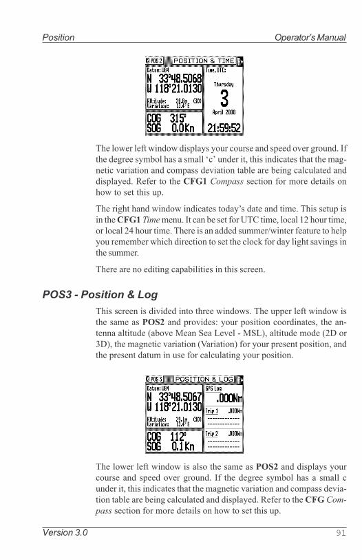
Version 3.0 91
Position Operator�s Manual
The lower left window displays your course and speed over ground. Ifthe degree symbol has a small �c� under it, this indicates that the mag-netic variation and compass deviation table are being calculated anddisplayed. Refer to the CFG1 Compass section for more details onhow to set this up.
The right hand window indicates today�s date and time. This setup isin the CFG1 Time menu. It can be set for UTC time, local 12 hour time,or local 24 hour time. There is an added summer/winter feature to helpyou remember which direction to set the clock for day light savings inthe summer.
There are no editing capabilities in this screen.
POS3 - Position & Log
This screen is divided into three windows. The upper left window isthe same as POS2 and provides: your position coordinates, the an-tenna altitude (above Mean Sea Level - MSL), altitude mode (2D or3D), the magnetic variation (Variation) for your present position, andthe present datum in use for calculating your position.
The lower left window is also the same as POS2 and displays yourcourse and speed over ground. If the degree symbol has a small cunder it, this indicates that the magnetic variation and compass devia-tion table are being calculated and displayed. Refer to the CFG Com-
pass section for more details on how to set this up.

92 Version 3.0
Operator�s Manual Position
The right hand window indicates your accumulated mileage since theCDU was first turned on.
You will also find two Trip Reset softkeys if you press the EDIT key.Two trip logs are provided so that you can log the mileage for:
a) the current leg or day of your trip; and
b) the entire trip.

Version 3.0 93
Position Operator�s Manual
GPS
Several GPS and DGPS screens are available under the GPS functionkey. The GPS/DGPS functions are highly interactive with these CFG1
menu selections:
Ø GPS - sets the lowest elevation at which a satellite will be tracked.Ø DGPS - sets the internal beacon receiver to Auto, DGPS only, or
Off.
GPS1 - GPS Status Screen
There are two windows in this display. The left window has twelvegraphic Power Bars representing the twelve GPS receiver channels ofthe MX smart antenna. The PRN (PseudoRandom Number) under eachpower bar represents the satellite ID number assigned or being trackedon that channel. The power bars indicate the valid receiver powerrange from 30 to 50. If a power bar is empty, but a PRN number islabeled under the power bar, then the identified satellite is not cur-rently being tracked.
The right window indicates where the satellites are located in the skyrelative to your present position. The outer ring represents 0° eleva-tion. The inner ring represents 45° elevation. The center represents 90°elevation and your present position. Under normal conditions, thebest satellites to track are usually between 15 and 75 degrees in eleva-tion.
GPS2 - GPS Health Screen
There are two windows in this display, the top window is a table indi-cating the satellite health status. The PRN (PseudoRandom Number)ID table is divided into columns and rows. the rows represent the 10sdigit of the ID number and the columns represent the 1� digit of the IDnumber. The satellite system consists of up to 32 satellites. The IDnumbers are called PsuedoRandom Number to denote an ID number

94 Version 3.0
Operator�s Manual Position
for each satellite regardless of the Satellite Vehicle Number (SVN).
To find a particular satellite ID, for example PRN24, go down the lefthand column and locate the 10�s digit 2. Then go across the row untilyou intersect with the 1� digit in this case 4.
The legend on the right of the table explains what each of the satelliteindicators represent.
You can deselect a particular PRN# by doing the procedure below:
1. Press the EDIT key.
2. Scroll to the PRN number desired.
3. Highlight �force unhealthy� softkey, press ENT to change the valueto �-�.
4. Press the EDIT key to exit.
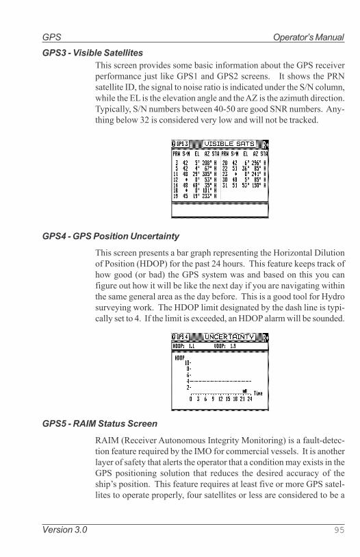
Version 3.0 95
GPS Operator�s Manual
GPS3 - Visible Satellites
This screen provides some basic information about the GPS receiverperformance just like GPS1 and GPS2 screens. It shows the PRNsatellite ID, the signal to noise ratio is indicated under the S/N column,while the EL is the elevation angle and the AZ is the azimuth direction.Typically, S/N numbers between 40-50 are good SNR numbers. Any-thing below 32 is considered very low and will not be tracked.
GPS4 - GPS Position Uncertainty
This screen presents a bar graph representing the Horizontal Dilutionof Position (HDOP) for the past 24 hours. This feature keeps track ofhow good (or bad) the GPS system was and based on this you canfigure out how it will be like the next day if you are navigating withinthe same general area as the day before. This is a good tool for Hydrosurveying work. The HDOP limit designated by the dash line is typi-cally set to 4. If the limit is exceeded, an HDOP alarm will be sounded.
GPS5 - RAIM Status Screen
RAIM (Receiver Autonomous Integrity Monitoring) is a fault-detec-tion feature required by the IMO for commercial vessels. It is anotherlayer of safety that alerts the operator that a condition may exists in theGPS positioning solution that reduces the desired accuracy of theship�s position. This feature requires at least five or more GPS satel-lites to operate properly, four satellites or less are considered to be a

96 Version 3.0
Operator�s Manual GPS
caution or unsafe RAIM condition. If the statistical RAIM error ex-ceeds a selected limit (100 meters default) a �RAIM Unsafe (R-)� or�RAIM Caution (R?)� alarm will be indicated in the MX CDU. Thismeans that the RAIM estimated position error is equal or greater thanthe preset limit. The operator is advised to take extra precautionarymeasures when using the navigation solution until the RAIM indica-tor switches to �RAIM safe R+� condition. When less than 5 satel-lites are receivable a �RAIM Caution� will be indicated.
The GPS5 screen shows the position Lat/Long, height of antenna,HDOP, number of satellites used, the satellite ID number that maycause the statistical error and its bias value. It also shows a tablecontaining the PRN numbers of satellites in use, their residual errorsand elevations. Below it is the RAIM Status indicator and time. TheRAIM icon is shown on the top-right corner of the display.
Position errors may be caused by unhealthy satellites, incorrectpseudoranges, poor DGPS corrections and excessive atmospheric in-terference. When the RAIM caution or RAIM unsafe alarm is on, theGPS/DGPS accuracy may be degraded but still usable when navigat-ing in open waters.
When the RAIM option is enabled an icon is posted on the top rightcorner of all screens.
- means RAIM safe condition - means RAIM Unsafe condition, position errors exceeded the
range limit specified under the CFG/GPS/Accuracy Rng. - RAIM Caution. Not enough satellites are available for proper
RAIM calculation.
The GPS5 RAIM screen works interactively with the GPS/RAIM menuunder the CFG key.

Version 3.0 97
GPS Operator�s Manual
Use the procedure below to activate the RAIM feature;1. Press the CFG key.2. Scroll down to the GPS menu.3. Press the EDIT key to bring up the cursor.4. Scroll down to �RAIM: .....No�5. Highlight the Change softkey and press ENT to switch it to �Yes�.6. Scroll down to �Accuracy Rng 10-100m: 100� to change the range.
Otherwise you may skip this step. 100 meters is the default value.
Note: The GPS5 RAIM Status screen is available in MX51x models with pro-
gram version 3.0 and using the MX521 or MX525 antenna sensors.
Warning:
THE MX51X AND RAIM FEATURE IS AN AID TO NAVIGATION ONLY. UN-
DER NO CIRCUMSTANCES SHOULD IT BE USED IN LIEU OF AUTHO-
RIZED GOVERNMENT CHARTS. ITS ACCURACY CAN BE AFFECTED BY
MANY FACTORS SUCH AS EQUIPMENT DEFECTS, ENVIRONMENTAL
CONDITIONS, OR IMPROPER OPERATION. THE USER IS RESPONSIBLE
FOR SAFE NAVIGATION OF THE VESSEL. THIS INCLUDES CONSULT-
ING AUTHORIZED GOVERNMENT CHARTS AND EXERCISING COMMON
PRUDENCE AND NAVIGATIONAL JUDGEMENT AT ALL TIMES.

98 Version 3.0
Operator�s Manual GPS
GPS6 - DGPS STATUS
There are several windows in this display, the left hand windows aredivided into control and configuration windows. The right hand win-dow displays all the corrections that are being received. Shown belowis the GPS6 screen.
MX51x GPS6 Screen
Status will tell you whether the correction data is being decoded iserror free or not. Normally, Status will indicate either DGPS mode Off,
DGPS OK, Tracking or Searching (Automatic search mode) or No
Lock (Manual tuning mode). DGPS OK indicates that RTCM SC-104DGPS corrections are being received without errors within the Age
Limit set in CFG1 DGPS. These information originates from the MXsmart antenna beacon receiver. Searching indicates that the beaconreceiver is searching for the appropriate frequency and/or modulationof the beacon transmitter in automatic search mode. No lock indicatesthat the beacon receiver is not receiving DGPS corrections from theselected station in manual tuning mode. You might see the label Track-
ing, which indicates that a MSK beacon signal is present but DGPScorrections are not being received. This is usually caused by highnoise on the beacon receiver or external device.
If you press the EDIT key, you can select between Automatic beaconsearch mode, Manual beacon tuning mode, or Off. When the receiveris in the Manual tuning mode, you can use the cursor key to scrolldown into the large window below Station Selection and edit theReference Station name. The name you enter will always be associ-ated with the frequency to which you programmed the receiver. If youmove to another region that uses a frequency and name you previ-ously entered, the receiver will display the previously entered name.You can enter a new name for any manually tuned frequency at anytime.
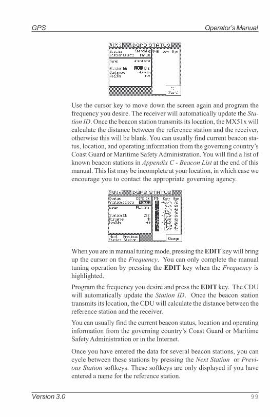
Version 3.0 99
GPS Operator�s Manual
Use the cursor key to move down the screen again and program thefrequency you desire. The receiver will automatically update the Sta-
tion ID. Once the beacon station transmits its location, the MX51x willcalculate the distance between the reference station and the receiver,otherwise this will be blank. You can usually find current beacon sta-tus, location, and operating information from the governing country�sCoast Guard or Maritime Safety Administration. You will find a list ofknown beacon stations in Appendix C - Beacon List at the end of thismanual. This list may be incomplete at your location, in which case weencourage you to contact the appropriate governing agency.
When you are in manual tuning mode, pressing the EDIT key will bringup the cursor on the Frequency. You can only complete the manualtuning operation by pressing the EDIT key when the Frequency ishighlighted.
Program the frequency you desire and press the EDIT key. The CDUwill automatically update the Station ID. Once the beacon stationtransmits its location, the CDU will calculate the distance between thereference station and the receiver.
You can usually find the current beacon status, location and operatinginformation from the governing country�s Coast Guard or MaritimeSafety Administration or in the Internet.
Once you have entered the data for several beacon stations, you cancycle between these stations by pressing the Next Station or Previ-
ous Station softkeys. These softkeys are only displayed if you haveentered a name for the reference station.

100 Version 3.0
Operator�s Manual GPS
The window on the right side of the display indicates which satelliteID�s are receiving corrections. When the PRN number is shown ininverse video, this indicates that the receiver is using the correction inthe navigation solution. The Corr value is the actual satellite rangemeasurement correction, given in meters. This value is typically be-tween -20 and +20. The Age value indicates how long it has been sincethe satellite range correction was generated, given in seconds.
GPS7 - DGPS Messages
This screen will display the messages received from the beacon stationbeing used. These messages may contain information regardingoperational problems and status or any scheduled equipmentmaintenance of beacon stations operating within the general area.
Note: The GPS screen is not active until the antenna is detected.

Version 3.0 101
Configuration Operator�s Manual
Configuration
The CFG screen includes setup and control of all of the MX51x�s
primary functions. There are more than 20 separate configuration items
in this screen. The display is divided into two windows. The left hand
window identifies the primary configuration items. The right hand win-
dow displays the current settings. Use the cursor key to select a con-
figuration item of interest, then press the EDIT key to edit the actual
settings. There are some settings which can not be changed; however,
these are displayed so that you have a better understanding of exactly
how the receiver is configured. The Item list is arranged alphabetically
based on the language chosen. This section of the manual is arranged
alphabetically for English. You may choose to skip to only the items
that interest you at first, then read this complete section at a later time.
Note: The configuration list is too long to show in one page of
the display. To view all of the configuration menu, scroll
through to the bottom of each list with the cursor key.
Alarms
This screen allows you to quickly see which alarms are active or not.
The list of available alarms is interactive with the remaining screens
described in this section. Therefore, changing the state of the alarm in
a screen such as Anchor from Off to On will also cause the anchor
alarm in this screen to go from Off to On. Likewise, if you turn the
anchor alarm from On to Off in this screen the Anchor screen will also
match this one.

102 Version 3.0
Operator�s Manual Configuration
Anchor - Anchor Watch Alarm
This screen allows you to setup an anchor watch alarm and maximum
drift radius after you drop the anchor. The MX51x will remember the
drop coordinates and provide an alarm if the antenna drifts beyond the
maximum distance you entered. If you are on a large commercial ship,
don�t forget that the anchor may be several hundred feet from the
MX51x antenna. You will need to consider this when setting in the
distance.
COG SOG - Course & Speed Filter Settings & Setup
This screen controls the Speed Over Ground (SOG) unit of measure
(meters per second, kilometers per hour, miles per hour, or knots). You
can also set a filter time to average your speed and course over ground
measurements. This helps to smooth these measurements on the dis-
play and NMEA output, a particularly useful tool for slow moving
vessels. The default filter setting is 2.0 seconds.

Version 3.0 103
Configuration Operator�s Manual
Compass - External Compass Input & Magnetic Variation
Table
The MX51x will accept compass input using the NMEA 0183 data
record of xxHDT, xxHDG, xxHDM, xxHCC, xxHCD, xxVHW, or any of the
above. The �xx� refers to the Talker Identifier as specified in the NMEA
0183 standard. It will accept these data records vitually from any talker
ID, and from any version (1.5 or higher) of the NMEA 0183 standard.
To implement this feature, change Compass Connected to Yes.
Identify the appropriate input port that the compass connects to the
CDU by using the Change softkey.
Select whether or not the MX51x should give an alarm if data is not
received on the input port.
Select the compass type, either Magnetic, Gyro, or MX575. Only the
NMEA 0183 records identified above are accepted for the gyro input.
Magnetic:
Select the magnetic deviation method: either In Compass - the de-
viation is corrected before being sent to the MX51x; or In Naviga-
tor - the deviation is corrected by editing a deviation table (Edit
Table softkey) in the MX51x.

104 Version 3.0
Operator�s Manual Configuration
Gyro:
Set the constant Gyro Heading Offset (or bias) if any.
Specify the input NMEA 0183 record for the Input Sentence.
HDT, HDG, HDM, HCC, HCD, VHW, or Any.
MX575:
There are two ways the MX575A DGPS compass can be con-
nected to the MX51x, namely:
� PORT3 as source of Positioning, Heading and ROT.
� PORT1 (or 2) as source of Heading and ROT only
If the MX575 is used as a positioning and heading device on
NMEA Port3, set Data input port no to 3. This will automatically
configure the MX575 to work at 19,200 Baud rate and the HDG
output will be set to 10 Hz on power up.
If the MX575 is used as a heading & ROT device only, set Data
input port no to the port number used (1 or 2) other than port 3.
(See MX575 Satellite Compass Installation & Operation
Manual for details).
Set the constant MX575 Heading Offset (or bias) if any.

Version 3.0 105
Configuration Operator�s Manual
Datum - Current Position Calculation
This screen controls which datum the MX51x uses to display the po-
sition Lat/Lon. There are over 100 datums to choose from. Appendix A
provides a complete list of available datums. You can enter an offset to
WGS-84 if your specific datum is not provided for in the MX51x. Use
the Previous or Next softkeys or the cursor key to scroll through the
list until you find the datum you need. Highlight Escape then press
ENT to go back to the original datum displayed when you first pressed
the EDIT key.
Depth - NMEA Input Control
This screen allows you to configure the depth unit (meters, feet, or
fathoms) for the NAV 4 and TIDE 1 screens .
Depth information is accepted by the MX51x from the NMEA 0183
data sentence DBK, DBS, DBT, or DPT on any input NMEA port. Refer
to the Appendix F of this manual for hardware interface instructions.
Press the EDIT key and move the cursor to the Echo Sounder Con-
nected line. Press tyhe ENT key to Change softkey to activate the
input data options described below:
Depth Unit - select between meters, feet, or fathoms. This data field
sets the depth unit displayed in NAV 4 and TIDE 1, regardless of
whether a sensor is connected or not.

106 Version 3.0
Operator�s Manual Configuration
Echo Sounder Connected - causes the MX51x to look for one of the
appropriate NMEA 0183 data sentences when set to Yes.
Data Input Port No. - Select the appropriate NMEA 0183 port that the
sensor is connected to (Port 1 or 2). Ports 3 and 4 are reserved for
the Smart antenna controls.
Offset - Input the appropriate offset for the sensor, based on the mea-
surement you are most interested in. If your boat draws about the
same amount of water each time you use it, you may want to put in
the difference between the sensor and the waterline height. If your
boat�s draught changes from one trip to another, as would be the
case when the MX51x is used on a freight ship, you may want to
put in the difference between the sensor and the lowest point of
the ship�s hull.
Shallow Alarm Active - allows you to receive an alarm if the sensor
receives depth data lower than the limit you set in Alarm Limit
(below). The default setting is No.
Alarm Limit - allows you to specify at what depth you want an alarm to
activate. This alarm limit is enabled by the Shallow Alarm Active
selection of Yes.
Alarm If No Data - Allows you to receive an audible and visual alarm if
NMEA 0183 data is not being received on the data port at regular
intervals (typically every few seconds). The available choices are
Yes (default) and No.
Input Sentence - Specifies the NMEA 0183 data sentence to read the
depth data from. The available choices are Any (default), DPT,
DBS, DBT, or DBK sentence. It is better to specify the appropriate
sentence because more than one method of reporting depth may
be available on the port.
The window in the lower portion of the screen allows you to see the
depth data that is received on the data port (Input:) and the data that
is actually displayed in NAV 4 (Used Value:).

Version 3.0 107
Configuration Operator�s Manual
DGPS - DGPS Configuration
This CFG menu allows you to control the built in beacon receiver in the
smart antenna unit.
DGPS Menu
DGPS Mode:
Auto - sets the smart antenna to automatically switch between
DGPS or GPS modes. This is the default setting. If DGPS cor-
rections are being received and their age is less than the Max
Age limit, the MX51x will operate in DGPS mode (assuming
you are receiving corrections for enough satellites to operate
in DGPS mode). Otherwise, the receiver operates in GPS posi-
tioning mode.
The traffic light will be green when it is in DGPS mode.
When it drops to GPS mode, a DGPS symbol will be displayed
(indicating Non Differential GPS mode), and the yellow and
green traffic light will be on.
Use this mode when maximum navigation coverage is more
important than accuracy. Reverting to GPS mode will degrade
the overall navigation results, but it is better than no naviga-
tion results at all in most circumstances.
DGPS Only - sets the smart antenna to only provide DGPS posi-
tion fixes. If corrections are being received and their age is less
than the Max Age limit, the MX51x will operate in DGPS mode
(assuming there are enough corrections to operate in DGPS
mode). Otherwise, the antenna will not provide any position
fix at all.
Use this mode when accuracy is more important than maximum
navigation coverage. It is recommended to set the Max Age to
30 seconds in this mode.

108 Version 3.0
Operator�s Manual Configuration
Off - sets the smart antenna to operate in GPS mode only.
Max Age -sets the maximum age limit that the last received RTCM
correction will be applied to the satellite range measure-
ment in the receiver. The default setting is 600 seconds. The
MX51x will accept values from 10 to 999 seconds. Due to the
removal of the S/A dithering from the satellite signal, you may
now use values of 600 seconds in the maximum age and still be
very accurate.
Message 16 Alarm - sets the alarm to On or Off if a reference station
text message is received. The default setting is Yes. Received
(Type 16) beacon messages can be displayed on the GPS7
screen, regardless of the alarm setting.
Alarm For No Corrections - sets the alarm to on or off if DGPS correc-
tions are not received within the Max Age. The default setting
is Yes. If the alarm is set to Yes, you will notice that the MX51x
drops out of DGPS mode and into the mode selected in DGPS
Mode described earlier in this section at the same time the
alarm sounds.
Alarm on health change - Sets the alarm to On or Off if a satellite
becomes unhealthy or unusable.
WAAS/EGNOS enabled - sets the source of differential correction to
come from satellite based augmentation system such as US-WAAS
or European-EGNOS system. Although this systems are available,
they are still non-IMO compliant. Use of these differential correc-
tion sources should be done with great caution.
External DGPS Enabled - gives the user the capability to accept RTCM
SC-104 corrections from an external beacon unit (receing the Coast
Guard or a Private Beacon Reference Station). The MX51x allows
you to control the baud rate of SC-104 Data input port. The follow-
ing baud rates can be used: 2400, 4800, 9600 or 19200 Bauds.
Note: WAAS/EGNOS and External RTCM are available only for the
MX521A, MX525A smart antennas or MX575A GPS Compass.
The MX421-10 GPS smart antenna can use external RTCM
correction only.

Version 3.0 109
Configuration Operator�s Manual
DR - Dead Reckoning
The DR (Dead Reckoning), is an added navigation feature of the MX51x
in the event that there is no GPS positioning available. This feature
requires external speed log and heading sensor inputs to work prop-
erly.
When the DR setting is set to �Yes� and appropriate compass/heading
and speed log sensors are connected and activated, the MX51x will
automatically switch to DR calculation when the GPS positioning be-
comes unavailable. A DR icon on the top right corner of the display
indicates that the position displayed is derived from DR calculation.
To set the DR to �Yes� , scroll down to DR menu then press the EDIT
key. Press the ENT key to activate the �Change� softkey. Press the
EDIT key again to exit the edit mode.
Dual Control - Dual Station Control
This screen sets the functional control between two or more MX51x
CDU�s in a LAN network. The default setting is No. When this selec-
tion is changed to Yes, one MX51x is set to Master, the other MX51x is
set to Slave. Up to five MX51x units can be networked together using
the LAN port. The MX51x connected to the antenna is normally the
Master unit and the other member/s can be either slaves or repeaters.
The Slave unit/s will share a common waypoint and route database
with the master. It can also make changes in some of the configuration
settings. A slave unit can be made into a Repeater. Repeaters only act
as a display unit. They cannot be used to change configuration set-
tings. Once an MX51x is set as a repeater it will require a special
password (which is set by the Master unit in CFG1/Security) to change
it back to a slave. Whether a unit is a slave or repeater, it will still share
a common waypoint and route database as the master. Refer to Appen-
dix D for more detailed information about the dual-control and multiple
unit control setup and operation.�

110 Version 3.0
Operator�s Manual Configuration
Note: CFG1/LAN menu must be setup before enabling the Dual-
Control feature. A dual control system consists of one Master and
one Slave. A Multiple Unit Control (MUC) system consists of one
Master, at least one Slave (maximum of two), and up to three (if any)
Repeaters. A multiple unit control system must contain a minimum of
three MX51x and a maximum of five MX51x units altogether.
Warning: In a Multiple Unit Control configuration, this option must
be enabled (by changing Dual Control to Yes) for all Slave and
Repeater units before enabling it in the Master unit.
MX51x Dual Control Menu
GPS - Elevation Mask Control
This screen controls the elevation mask angle, or the angle above the
horizon, at which the MX51x will attempt to track a satellite. Satellites
with an elevation below this angle will be tracked but will not be in-
cluded in the position solution. You can set the elevation limit to any
value up to 90°. For most marine applications, the default limit of 5° is
appropriate.
The Antenna Offset allows you to virtually offset your antenna
location. That is, if you are forced to place the antenna in a location
other than where you want your position fix calculated (due to
superstructure or other high power antennas), you can place the
antenna in a practical location. Then enter the appropriate Antenna
Offset, and the MX51x will calculate your position in the place where
you would have preferred to place the antenna.

Version 3.0 111
Configuration Operator�s Manual
The RAIM menu is available only in MX51x models where the RAIM
feature is enabled. For more detailed information about RAIM, please
refer to Page 98 of this manual. Standard MX51x CDU will only show
the Elevation mask and Antenna offset menu items.
Initial Pos - Initial Position Entry
This screen is provided to help the GPS receiver in the smart antenna
to get a faster first position fix. While the smart antenna is capable of
computing its position without any user input, this feature can cause
a position fix to occur several minutes earlier. Another time this feature
is useful is when the MX51x has been moved over 300 miles from the
last location it was used while in the off condition. Again, the MX51x
will calculate a position fix without any user input in this circumstance.
However, moving the MX51x to a new location and not inputting a
new initial position will cause the receiver to select a satellite constel-
lation consistent with the last known receiver coordinates. In this event
the MX51x may �get lucky� and find common satellites between the
old position and the new location, or it may take up to 20 minutes to go
through all of the constellation possibilities. Note that the MX51x will
stay on the original constellation for 15 minutes before attempting
other constellation possibilities. We assume the MX51x will be turned
on and off in the same general area each time, and we provide the unit
every opportunity to try and track satellites at the last known coordi-
nates.

112 Version 3.0
Operator�s Manual Configuration
LAN - Local Area Network
This feature allows the MX51x to communicate with another MX51x
via LAN interface (RJ45). This data link is used by the MX51x for dual
control, integrity monitoring, and multiple control applications. Be-
low are IP addresses used by the Host and Client units within its local
network.
MX 510 IP Address Table
To activate LAN, press the EDIT key and press the ENT key to activate
the Change softkey to change LAN Enabled to Yes. Use the Change
softkey to modify the options described below:
Type - select between Host or Client. In a dual or multiple unit control
system, the Master will be the Host and the Slave(s) will be the
Client(s).

Version 3.0 113
Configuration Operator�s Manual
Number - this option is only available when Type is Client. The avail-
able values are 1, 2, 3, or 4 (which determines the IP address of the
CDU). Each Client has to be assigned with a unique number (1, 2, 3 ,
or 4). Any two or more Clients with the same number will create
an IP address conflict, and therefore, will activate an IP Conflict
Alarm. Please refer to the previous IP address table for the designated
IP numbers.
When the connection is successful, the Status will display ESTAB-
LISHED.
LAN Output (NMEA 0183 OVER IP)
This screen is very similar to the NMEA Out screens. It sets the
specific NMEA 0183 parameters. The default setting is No. When this
selection is changed to Yes, you can turn on individual data records,
and transmit them using the Local Area Network (LAN) connection.
This feature can be used to integrate the MX51x to an Integrated
Bridge System by connecting the CDU to a PC-based IBS system
using LAN (RJ45).

114 Version 3.0
Operator�s Manual Configuration
Language - Language Configuration
The MX51x supports 9 languages: English, Dutch, French, Finnish,
German, Italian, Spanish, Swedish and Danish
Press the EDIT key. Use the cursor key to scroll down the list until you
find the desired language. Press the EDIT key again. The CFG menu
list will sort the menu selections in alphabetical order based on the
language selected.
Lighting - Display/Keyboard Light & Contrast Control
There are two basic display setups. The light function key allows
you to instantly switch between two predefined screens (Daylight &
Nightlight).
Save on power off - When enabled, the MX 510 CDU will save
waypoints, routes, and system configuration to flash memory be-
fore powering off.
Restore on power on - When enabled, the MX 510 CDU will restore the
saved waypoints, routes, and system configuration from flash
memory upon powering on the unit.

Version 3.0 115
Configuration Operator�s Manual
Log - Speed Log Input (Pulse or NMEA 0183)
This screen controls the input port (NMEA-0183 or Pulse) and format
of the speed log input to the MX51x. In the default condition, the
speed log is not connected. NMEA 0183 speed is accepted from the
xxVHW data sentence originating in any of the version 1.5, 2.0, 2.1, or
2.3 format where xx is a valid talker ID as specified in the NMEA 0183
standard. The CDU will also accept speed log pulse input, with pulses
of up to 1.5 kHz. Refer to the Appendix F of this manual for the wiring
interface instructions.
NMEA 0183 (VHW) Input Screen Pulse Input Screen
NMEA Input:
Data Input Port No. - Select the appropriate NMEA input port as
determined by the hardware interface. Refer to the Appendix F
of this manual for wiring connections.
Alarm If No Data - Causes an alarm to activate if data is not re-
ceived on the port you defined within 10 seconds when Yes is
selected (the default condition). To disable the alarm, select
No with the Change softkey.
Correction Factor - Allows you to make minor adjustments to
observed or measured errors in your speed through water cal-
culation. The input value will be multiplied by this value be-
fore it is used in the MX51x. The default value is 1.00.
Digital Pulse Input:
Pulses Pr. Nm - This is the calibrated pulses per speed unit value
that you must get from the speed log manufacturer.
Alarm If No Data - Causes an alarm to activate if data is not re-
ceived on the port you defined when Yes is selected (the de-
fault condition). To disable the alarm, select No with the Change
softkey.

116 Version 3.0
Operator�s Manual Configuration
Correction Factor - Allows you to make minor adjustments to
observed or measured errors in your speed through water cal-
culation. The input value will be multiplied by this value be-
fore it is used in the MX51x. The default value is 1.00.
Both input types have a window in the lower portion of the display
which indicates the input value in real time. If you input a calibrated
pulse rate, you can check for the appropriate speed right here.
You will be able to view the speed log information in the NAV4
screen when it is implemented in future software.
Log Pulses - GPS SOG Log Pulse Output
This screen controls the output port (Pulse) of the speed over ground
log output from the MX51x CDU at a user-defined pulse rate per nau-
tical mile. This output is normally used to feed GPS SOG to an ARPA
radar. The default state is not active, and set to 200 pulses per nautical
mile. The Log Pulses output connection is done using the 8-pin AUX
connector.
Refer to the Appendix F of this manual for the hardware interfacing.
Activate the output by selecting Yes to Emulation Enable and set the
pulse rate based on the device that you are connecting to.

Version 3.0 117
Configuration Operator�s Manual
LORAN-C Integration
This feature will be available only when the optional Loran-C license is
purchased and activated. The MX 51x has two selections for Loran-C inte-
gration (Raytheon and Locus).
Raytheon:
To implement this feature, change LORAN-C connected to Yes.
Identify the appropriate input port (1 or 2) that the LORAN-C device
connects to by using the Change softkey.
Select the appropriate Version Number with the range from 0 to 9.
The Antenna offset option of the LORAN-C feature is tied to the
Antenna offset from the GPS feature. Note that any changes you make to
the Antenna offset in LORAN-C will also modify the Antenna offset in the
CFG1/GPS screen. The Antenna offset allows you to virtually offset your
antenna. That is, if you are forced to place the antenna in a location other
than where you want your position fix calculated (due to superstructure or
other high power antennas), you can place the antenna in a practical
location. Enter the appropriate Antenna offset, and the receiver will
calculate your position in the place where you would have preferred to
place the antenna.
After the LORAN-C (Raytheon) feature is enabled, you will have 3 new
screens (POS 4, POS 5, POS 6), which display the following information:
• POS 4 - GPS/LORAN-C Combined Position
• POS 5 - LORAN-C Calibrated Position
• POS 6 - LORAN-C Stand Alone Position

118 Version 3.0
Operator�s Manual Configuration
The POS 4 screen displays the GPS/LORAN-C combined position and
navigation modes received from the $PMVX1 message (which is based on
(D)GPS if GPS is available, and based on (D)GPS calibrated LORAN-C
position if GPS is not available) from the LORAN-C receiver. The
$PMVX1 message is formatted just like the NMEA GGA message, except
that its GPS quality indicator ranges from 0-5. The GPS quality indicator is
displayed as a navigation mode on the POS 4 screen.
The POS 5 screen displays the (D)GPS calibrated LORAN-C position
received from the GLL message from the LORAN-C receiver.
The POS 6 screen displays the stand-alone (uncorrected) LORAN-C
position received from the RMA message from the LORAN-C receiver.

Version 3.0 119
Configuration Operator�s Manual
When Loran-C (Raytheon) option is enabled, the MX51x gives the option
to accept EUROFIX DGPS corrections instead of the External DGPS correc-
tions under the CFG1/DGPS Configuration screen.
Locus:
To implement this feature, change LORAN-C connected to Yes.
Identify the appropriate input port (1 or 2) where the LORAN-C device
connects to by using the Change softkey.
Select the chain selection mode, either Auto or Manual.
Auto:
When the chain selection mode is Auto, you can view the list of
current chains by using the left or right arrow key to highlight the List
Chains softkey and press the ENT key to select. You can also choose
the desired region by using the left or right arrow key to highlight the
Change softkey and press the ENT key to select.
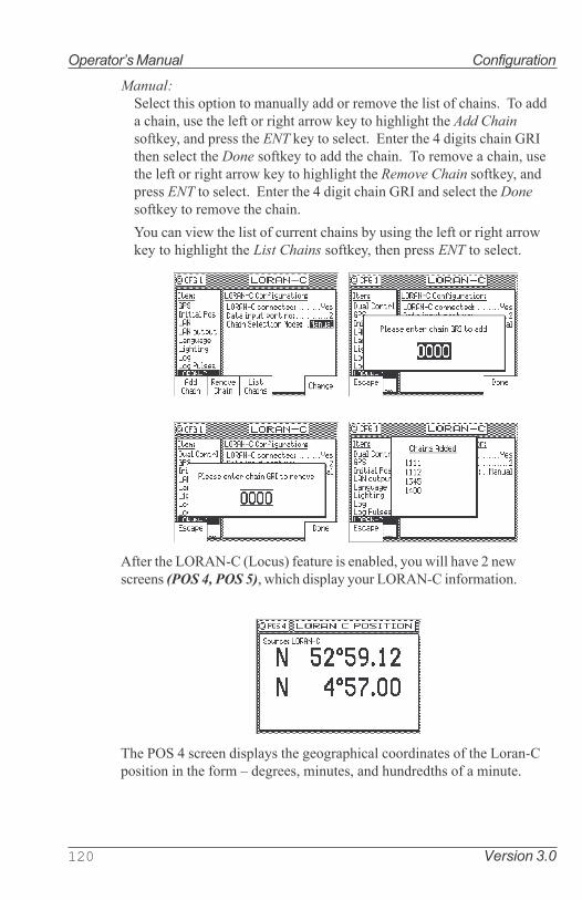
120 Version 3.0
Operator�s Manual Configuration
Manual:
Select this option to manually add or remove the list of chains. To add
a chain, use the left or right arrow key to highlight the Add Chain
softkey, and press the ENT key to select. Enter the 4 digits chain GRI
then select the Done softkey to add the chain. To remove a chain, use
the left or right arrow key to highlight the Remove Chain softkey, and
press ENT to select. Enter the 4 digit chain GRI and select the Done
softkey to remove the chain.
You can view the list of current chains by using the left or right arrow
key to highlight the List Chains softkey, then press ENT to select.
After the LORAN-C (Locus) feature is enabled, you will have 2 new
screens (POS 4, POS 5), which display your LORAN-C information.
The POS 4 screen displays the geographical coordinates of the Loran-C
position in the form � degrees, minutes, and hundredths of a minute.

Version 3.0 121
Configuration Operator�s Manual
The POS 5 screen displays the Station GRI, Time Difference (TD),
Warning status (CYCLE, BLINK), and Signal-to-Noise (SNR) data for
different slave stations of a particular Loran-C chain being used.
This screen also allows you to scroll through data of different chains
if multiple chains are being used.
1. Press EDIT key to bring up the PREVIOUS CHAIN and NEXT
CHAIN softkeys.
2. Use the left or right arrow key to highlight the PREVIOUS
CHAIN or NEXT CHAIN softkey then press the ENT key to
select and view data from different chains (if more than one
chains are being used).
3. Press the EDIT key once more to exit the softkey menu.
Memory
This screen allows the user to have the option to save and restore
waypoints, routes, and system configuration using the MX51x inter-
nal flash memory.
Navigation - Navigation Method & Waypoint Pass Criterion
Control
This screen sets the navigation mode to Rhumb Line or Great Circle,
Cross-track Error limits and alarms, Waypoint Pass Criterion, and
Waypoint Approach alarms. These settings have a direct effect on
your route calculation and how data is displayed in the NAV and PLOT
screens.

122 Version 3.0
Operator�s Manual Configuration
Navigation:
Sets navigation to Rhumb Line (default) or Great Circle mode.
Note: When the navigation mode is set to Great Circle, the PLOT
screens will not show your course or cross-track error lines.
Range Unit:
Sets the unit of measure for all range calculations. You can choose
between Nautical Mile (default), Nautical Mile & Meters, Nauti-
cal Mile & Feet, Statute Mile, Statute Mile & Meters, Statute
Mile & Feet, Kilometers, and Kilometers & Meters.
Direction:
Sets all displays which indicate direction to True or Compass. If
you want the MX51x to agree with your magnetic compass, select
Compass. The MX51x will automatically add or subtract the appro-
priate magnetic variation and deviation. Enter the compass devia-
tion table into the MX51x in this screen. You can differentiate be-
tween True and Compass settings by observing the degree symbol
on any bearing or heading display. True is indicated by a degree
symbol (°), Compass is indicated by a degree symbol with a small c
under the symbol ( c ).

Version 3.0 123
Configuration Operator�s Manual
XTE Limit:
Sets the distance left or right from the course line you consider to
be the maximum allowable off-track error (known as cross-track
error, �XTE�). The PLOT screens will display the scaled cross-
track error distance. The NAV screens will indicate the cross-track
error in numerical format and present the cross-track error graphi-
cally scaled left or right of the course line.
XTE Alarm:
Causes an alarm to sound if your position exceeds the maximum
XTE Limit defined above when Yes is selected. To disable the alarm,
select No (default) with the Change softkey.
WPT Pass Criterion:
Sets the waypoint passed determination method. There are five
methods available:
Complex:
This is the default setting. Passing the waypoint is determined by
reaching an imaginary perpendicular line. Or you can pass the
waypoint by crossing the bisector line of an acute angle (providing
you are within 0.2 NM of the waypoint) or an obtuse angle between
your present course line and the next leg of your route.
Manual:
Passing the waypoint can only be accomplished by manually skip-
ping a waypoint. Refer to the Skipping and Unpassing Waypoints

124 Version 3.0
Operator�s Manual Configuration
in the Route section of this manual.
This is a great way to perform station keeping maneuvering. Refer
to the Plot Screen Use Examples in the Plot section for further
details on this application.
Distance:
Passing the waypoint is determined by reaching an imaginary circle
around the waypoint, the radius of which you can define in WPT
Pass Distance. The default value is 0.10 Nm.
If you set this distance to 0.00, you will never pass the waypoint.
This is a great way to perform station keeping maneuvering. Refer
to the Plot Screen Use Examples in the Plot section for further
details on this application.
Bisector Line:
Passing the waypoint is determined by reaching the bisector line
of an acute or obtuse angle between your present course line
and the next leg of your route.
Perpendicular Line:
Passing the waypoint is determined by reaching an imaginary per-
pendicular line from your present course line.
Approach Alarm:
Causes an alarm to sound if your position is within the radius
defined in Approach Distance (below) when Yes is selected. To
disable the alarm, select No (the default condition) with the Change
softkey.
Approach Distance:
Sets the waypoint approach alarm distance (above) to sound if
your position is within the radius defined. The default setting is
0.30 Nm. This is a convenient tool for large boats and ships that
need to perform Transfer and Advance maneuvers prior to reach-
ing the waypoint.

Version 3.0 125
Configuration Operator�s Manual
Autopilot Alarm:
Causes an alarm when your position is outside the cross-track
error limit defined in XTE Limit (above) or when you change course
to a new leg in your route (manually or automatically passing a
waypoint) when Yes is selected. It also causes the NMEA data
records of APA, APB, and XTE to change their reported status of
Valid to Invalid when you reach the waypoint of the current leg.
This tells the autopilot not to use the data from the MX51x. When
the alarm is canceled, which requires your highlighting of the Can-
cel Alarm softkey then press ENT (displayed during the alarm con-
dition), these data fields will revert to valid data and the autopilot
will accept the MX51x data again. This is provided as a safety
feature so that the boat does not turn toward a new direction
without your knowing of the impending change. To disable the
alarm, select No (the default condition) with the Change softkey.
NMEA Out 1 to n - NMEA 0183 Output Data Control
These screens set the specific NMEA 0183 output record param-
eters as well as the port control. The default setting is No. When
this selection is changed to Yes, you can turn on individual data
records. Refer to the installation manual of the device you inter-
faced with the MX51x to determine which output records are re-
quired. Refer to the Appendix F of this manual for MX51x hardware
interface information.
MX510 Model - has two user NMEA ports available, two antenna
ports (NMEA3 & 4) dedicated to the MX smart antenna, and one
Local Area Network (LAN) port.
MX512 Model - has 11 user NMEA ports, two antenna ports (NMEA
3&4), one LAN port and one VGA port.
Note: Pre plan your interface requirements to ensure all of your
interfacing needs are met. All NMEA Ports are RS-422
electrically. We recommend using these ports to inter-
face to a computer or other �single ended� interface.
The default condition of each port is Off. When you want to output
data on a NMEA port, scroll down the Item menu to the appropriate
NMEA Out port number and change Port Active to Yes. In doing so,
the MX51x will display all available NMEA 0183 output sentences.

126 Version 3.0
Operator�s Manual Configuration
MX510 NMEA Out Menu MX512 NMEA Out Menu
Scroll down the list using the cursor key to the desired NMEA 0183 sen-
tence. Highlight the Change softkey then press ENT to select On.
Highlight the Details softkey then press ENT to view the characteris-
tics for the NMEA record you select. If you notice that the top of some
text is cut off by the Capacity Needed window, this indicates that
there are more selections available than can fit in the window. Use the
cursor key to scroll down the list. Each record is controlled separately.
Generally speaking, the following controls are available to you for
most or all of the records:
Checksum On or Off - NMEA 0183 version 2.1 and above requires
that the checksum is present. Versions 1.5 and 2.0 do not re-
quire the checksum. The MX51x provides you the option of
turning the checksum on or off to provide flexibility in interfac-
ing.
Output Rate - maximum once per second, unless the Multi-Hertz
option is installed. Refer to the Total Load Is section which
follows.
Note: All position information contained in any data record is
output in the local datum selected in CFG/Position; ex-
cept GGA, which provides a selection in the Details screen
to output in either WGS-84 or the datum selected in CFG/
Position.

Version 3.0 127
Configuration Operator�s Manual
Most:
NMEA Version - Some of the NMEA 0183 records are no longer
supported by version 2.3. However, you may have an autopi-
lot, plotter, or other older model equipment that does not sup-
port the newer version of the NMEA 0183 standard. The MX51x
provides you the flexibility to interface using older versions of
the NMEA standard to support these devices.
Decimals In Lat/Lon - The software allows you to select from 2 to
5 decimal places in records containing position or waypoint
information.. The MX51x provides you the flexibility to match
the expected input on these devices.
Decimals In BRG or HDG - The MX51x allows you to select from
0 to 1 decimal places in records containing bearing informa-
tion.
xxx loads the port by - The NMEA 0183 standard limits the port
baud rate to 4800 bits per second. It is impossible to turn on
every NMEA 0183 data record on one port in the receiver at a
once per second output rate, due to the NMEA standard limi-
tation. xxx loads the port by tells you how much throughput
capacity is required to send the selected data record out the
port (where xxx is the NMEA data sentence identifier). If you
change the Output Rate, xxx loads the port by: value will
adjust to reflect the change after you move the cursor to the
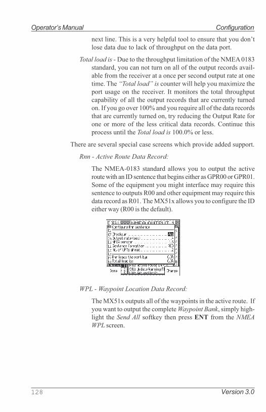
128 Version 3.0
Operator�s Manual Configuration
next line. This is a very helpful tool to ensure that you don�t
lose data due to lack of throughput on the data port.
Total load is - Due to the throughput limitation of the NMEA 0183
standard, you can not turn on all of the output records avail-
able from the receiver at a once per second output rate at one
time. The �Total load� is counter will help you maximize the
port usage on the receiver. It monitors the total throughput
capability of all the output records that are currently turned
on. If you go over 100% and you require all of the data records
that are currently turned on, try reducing the Output Rate for
one or more of the less critical data records. Continue this
process until the Total load is 100.0% or less.
There are several special case screens which provide added support.
Rnn - Active Route Data Record:
The NMEA-0183 standard allows you to output the active
route with an ID sentence that begins either as GPR00 or GPR01.
Some of the equipment you might interface may require this
sentence to outputs R00 and other equipment may require this
data record as R01. The MX51x allows you to configure the ID
either way (R00 is the default).
WPL - Waypoint Location Data Record:
The MX51x outputs all of the waypoints in the active route. If
you want to output the complete Waypoint Bank, simply high-
light the Send All softkey then press ENT from the NMEA
WPL screen.

Version 3.0 129
Configuration Operator�s Manual
The WPL record, as defined by the NMEA 0183 standard,
technically does not allow the output of waypoint descrip-
tions when interfacing to other devices such as Chart Plotters.
However, MX Marine realizes that with 2000 waypoints, you
have spent a lot of time preparing your library of waypoints
with definitions and symbols. You probably will want to record
these to a PC, just in case the memory in the MX51x fails in the
future. For this reason, we have provided you the option to
Include Waypoint Names in the WPL record to save your
waypoints to a PC or to meet the NMEA 0183 standard for
interfacing to other marine equipment. The definition of the
differences between these two formats is given in the WPT
section of this manual and in the NMEA 0183 format section in
the Appendix F of this manual.

130 Version 3.0
Operator�s Manual Configuration
Other Special Cases Affecting NMEA 0183 Records:
BWC, BWR, APA, APB, RMB, RMC, and Man Over Board (MOB):
During the period when the Man Over Board function is activated,
NMEA 0183 records which contain bearing and range data, such as
those identified above (but not limited to these), will reflect the
bearing and range back to the MOB position until the MOB func-
tion is canceled. Refer to the MOB section of this manual.
APA, APB, XTE, and the Navigation Autopilot Alarm:
Refer to the CFG Navigation section. When the Autopilot Alarm
is set to No, the MX51x always indicates a mode �A�, or valid data
to the autopilot or other marine device which might be receiving
this data. If the Autopilot Alarm is set to Yes, then the MX51x
changes the mode �A� to �V�, indicating invalid data when you
reach a waypoint or exceed your cross-track error limit set in the
CFG Navigation XTE Limit field. When the alarm is canceled, which
requires your highlighting of the Cancel Alarm softkey then press-
ing ENT (displayed during the alarm condition), these data fields
will revert to Valid data and the autopilot will accept the MX51x
data again. This is provided as a safety feature so that the boat
does not turn toward a new direction without you knowing of the
impending change.
Output Port Configuration Conflicts:
The NMEA output ports can only be assigned once. If you have
already defined a given port for one format, and you attempt to
define a different format for the same port, the MX51x will warn you
of the port conflict. The first format to be defined on a port main-
tains the port. The second format will be ignored.

Version 3.0 131
Configuration Operator�s Manual
Operation - General Setup and Control Settings
This screen controls a few basic operating settings:
Remember Display: When set to Yes (default), the MX51x remem-
bers the Page Number or screen you viewed the last time you
used a particular function. For example, if you normally moni-
tor the NAV3 display and you decided to look at the PLOT1
screen, the next time you press the NAV function, the MX51x
will automatically revert to the NAV3 screen immediately.
If you select No for Remember Display, the MX51x will always
display the first page of a function when you press the func-
tion key.
Edit Timeout: You can set the timeout limit between None (de-
fault), or 1 to 10 minutes. If you enter the edit mode on any
screen and have a timeout period other than None, the MX51x
will automatically exit the edit mode if no keys are touched and
the timeout period expires.
Preceding Zeroes: Places zeroes (0s) before directions less than
100° when Yes is selected. For example, 079°. Otherwise direc-
tions are shown without the leading zeros when No is selected
(default). For example, 79°.
Beeper: If you attempt to perform a key function that is not al-
lowed, you normally hear an Error Tone. This is performed
when the Beeper is set to On (default). If you don�t want to
hear the error or any other keyboard beep, set the Beeper to
Off.
Retain External Alarm: Allows the CDU to hold the external alarm
while the alarm condition still exist. When Retain external
alarm is set to On, the external alarm will normalize only when
the cause of alarm is corrected.

132 Version 3.0
Operator�s Manual Configuration
Engineering Display: This enables an expanded series of display
screens in some of the functions. In general, these screens are
used by the technician during troubleshooting or by MX
Marine engineers during development testing. Screens which
are relevant for troubleshooting are described in Appendix D
of this manual. The default setting is No. If you should enable
these screens, the MX51x will automatically turn them off the
next time power is cycled on the unit.
Demonstration Mode: This enables the MX51x to function as
though you are under way, even though you are completely
stationary. The default setting is No. When set to Yes, all three
Traffic Lights will be illuminated, and a D symbol is displayed
in the upper right corner of every display. Generally speaking,
this feature is used by MX Marine and your dealer for show
room or trade show demonstrations. However, you can use it
as a training tool until you become familiar with the MX51x. As
a safety feature, you can not use it to output NMEA 0183
records on the data ports to test and demonstrate other de-
vices such as autopilots, chart plotters, and radars. Refer to
Appendix E of this manual for a full description of the Demon-
stration Mode.
Organizer - Automated Message Reminders
This screen enables you to program the MX51x with up to 25 different
message reminders (up to 30 characters in length). You can program it
to alarm for shift changes, log entry intervals, medication intervals,
weather fax updates, etc.
Note: When the Organizer alarm is activated, the voltage on
the Alarm Output Port is also activated. If you have other
devices connected to this port, you might need to con-
sider what other systems will be affected when the alarm
sounds. MX Marine offers an External Alarm control op-
tion license that will allow you to control the internal and
external alarm settings individually. Check with your dealer
or MX Marine for details on External Alarm license op-
tion.
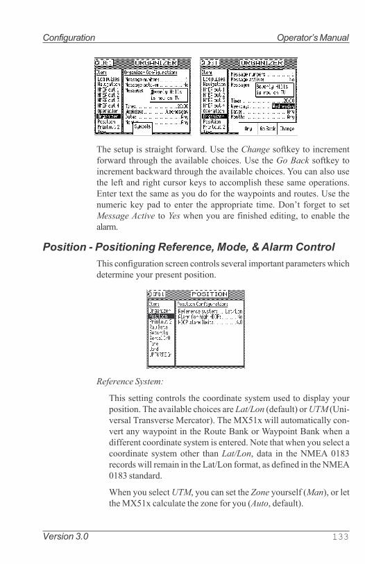
Version 3.0 133
Configuration Operator�s Manual
The setup is straight forward. Use the Change softkey to increment
forward through the available choices. Use the Go Back softkey to
increment backward through the available choices. You can also use
the left and right cursor keys to accomplish these same operations.
Enter text the same as you do for the waypoints and routes. Use the
numeric key pad to enter the appropriate time. Don�t forget to set
Message Active to Yes when you are finished editing, to enable the
alarm.
Position - Positioning Reference, Mode, & Alarm Control
This configuration screen controls several important parameters which
determine your present position.
Reference System:
This setting controls the coordinate system used to display your
position. The available choices are Lat/Lon (default) or UTM (Uni-
versal Transverse Mercator). The MX51x will automatically con-
vert any waypoint in the Route Bank or Waypoint Bank when a
different coordinate system is entered. Note that when you select a
coordinate system other than Lat/Lon, data in the NMEA 0183
records will remain in the Lat/Lon format, as defined in the NMEA
0183 standard.
When you select UTM, you can set the Zone yourself (Man), or let
the MX51x calculate the zone for you (Auto, default).

134 Version 3.0
Operator�s Manual Configuration
Alarm For High HDOP:
This allows the MX51x to create an alarm for HDOP values which
rise above a number that you determine. This indicates that posi-
tion accuracy is becoming bad, due to poor satellite geometry rela-
tive to your position and/or the number of satellites currently un-
der track. You may want to set the alarm to Yes if position accuracy
is critical to you. Otherwise this alarm is normally set to No.
HDOP Alarm Limit:
Sets the HDOP value which will cause the alarm to sound. The
default value is 4. The valid range is from 1.0 to 9.9. The higher your
HDOP value, the more error you will have in your position fix. Refer
to the GPS1 Current Satellite Status section of this manual for
more information about the HDOP value.

Version 3.0 135
Configuration Operator�s Manual
Printout (n) - Printer Output Control
This menu item controls the printer output sometimes required for
commercial shipping. The interface is accomplished on NMEA Out 2
port for the MX510 or NMEA Out 11 port on MX512 models. The
printer output is simple ASCII text designed to operate on any serial
line printer, including narrow column printers.
The MX51x has two print formats, namely: Full or Brief.
MX510 Printout2 Menu MX512 Printout11 Menu
A sample of the Full printer output format is given below:
MX510 Navigator
====================================
20:42:41 UTC 12 Apr 2002
POS Mode : DGPS 3D Datum:W84
Position : N 33 48.5056
W 118 21.0073
Altitude : 5.6 m
COG: 346 T SOG: 0.1 Kn
ROUTE: From WPT 0 To WPT 1
NAV Mode : RL XTE: .108L Nm
BRG: 345 T Dist: 2.51 Nm
SATS Used: 6 HDOP 1.4 VDOP 1.6
DGPS Age : 9s Station ID: 262
SW Vrs. 1.5 MX421 V4.84
------------------------------------------------------------------------
Route and DGPS information is printed if these functions are active.

136 Version 3.0
Operator�s Manual Configuration
Here is a sample of the Brief format without an active route:
MX510 Navigator
====================================
21:24:00 UTC 12 Apr 2002
POS Mode : DGPS 3D Datum:W84
POS: N 33 48.5124 W 118 21.0213
COG: 152T SOG: 0.1 Kn
------------------------------------
Here is a sample of the Brief format with an active route or MOB
condition:
MX510 Navigator
====================================
21:24:00 UTC 11 Aug 1997
POS Mode : DGPS 3D Datum:W84
POS: N 33 48.5124 W 118 21.0213
COG: 152T SOG: 0.1 Kn
BRG: 239T Dist: 27.4 Nm XTE:0.14L Nm
RTE: RL From WPT 1234 To WPT 1357
-------------------------------------------------------------------------
Sending: Causes the printer output to be turned On or Off (default).
Print Interval (Sec): Allows you to control how often the print out will
be sent to the printer port. The default value is 60 seconds, and the
valid range is from 1 to 9999 seconds.
Format: Allows you to choose either the Full or Brief formats de-
scribed above.
Bit Rate: This allows you to control the port interface baud rate to

Version 3.0 137
Configuration Operator�s Manual
match the printer or computer you are interfacing with. The avail-
able baud rates are: 600, 1200, 2400, 4800 (default), 9600 or 19,200.
Data Bits: This allows you to match the printer�s requirement of 7 or 8
(default) bit serial data.
Stop Bits: This allows you to match the printer�s requirement of 1
(default) or 2 stop bits.
Parity Check: This allows you to match the printer�s requirement of
None (default), Even or Odd parity.
Handshake: This allows you to match the printer�s requirement of No
(default), XON/XOFF or HW (Hardware; CTS, RTS ).
ROT (Rate of Turn)
The ROT configuration menu is available in the MX51x model. The
�ROT connected� mode can be toggled to YES or NO, by pressing the
EDIT key and then highlighting the �Change� softkey and press ENT.
Data input port no: ...2 (valid port selections are 1,2, or 3*)
Alarm if no data: ....No (�Yes� value sets the alarm to sound if no ROT
input data is detected in 5 seconds)
*Use MX575 ROT: ...No (�Yes� value would allow the MX51x to use
ROT data from Port 3 when the MX575 is
used as a positiong and heading device.
�No� value would allow the MX51x to use
ROT data from any available port other than
Port 3 when the MX575 is used as a heading
device only (See MX575 Satellite Compass
Installation and Operation Manual for de-
tails).
Security
The Security screen allows you to lock out the EDIT key in order to
keep crew members or visitors from changing settings that you have

138 Version 3.0
Operator�s Manual Configuration
made. Once this feature is enabled, a press of the EDIT key will require
the correct password to gain access. To disable the security functions,
you will be prompted to enter a 5 digit password. You will then be
prompted to reenter the password. The security function is then dis-
abled until you enter a new password through the CFG1 Security
screen again. Be sure to keep your password in a safe place. If you lose
your password, you will need to call the factory to reset the security
feature.
Serial I/O
This menu provides a means to verify the status and baud rate settings
of all the NMEA ports. Note that the NMEA ports 3 & 4 are reserved
for the Smart antenna GPS and Beacon receiver interface. You have no
control in these two ports. You can not change the baud settings in its
original values.
MX51x Serial I/O Menu

Version 3.0 139
Configuration Operator�s Manual
Time - Mode and Format ControlThis menu item sets the method in which time is displayed on the CDU.
Time System: Sets the time to UTC (default) or Local. When Local is
selected, several parameters associated with local time are displayed.
Time Format: Sets the time to either a 24 Hour (default) or 12 Hour
clock.
Time Offset: Sets the local offset to UTC time. 0:00 is the default.
Summer Time: Sets the local clock ahead one hour in the summer for
daylight savings time when set to Yes, or to the Local Offset time
when set to No.
The adjusted time value is displayed in the lower window so you can
verify the current time without having to leave the screen.
USB - USB Mass Storage Configuration
This option controls the saving and restoring of your waypoints, routes,
and system configuration via an external USB device. In the event
where you do a software upgrade for your MX51x CDU for example, all
your waypoints, routes, and system configuration will be lost. This
option allows you to save them to a USB device (i.e. USB flash drive)
beforehand, and restore them from your USB device after the software
upgrade is completed. This way, you do not have to manually re-enter
all your waypoints, routes, and system configuration settings.

140 Version 3.0
Operator�s Manual Configuration
To implement this feature, plug your USB device into the USB port of
the MX51x CDU first, and change USB Connected to Yes. Allow a few
moments for the CDU to read and detect your USB device. Ensure that
status displays Connected before continuing.
Select the data type, either Waypoints, Routes, Config, or All by using
the Change softkey.
Waypoints:
This sets the CDU to save (Save to USB softkey) or restore (Re-
store softkey) your waypoints using your USB device.
Routes:
Select routes will set the CDU to save (Save to USB softkey) or
restore (Restore softkey) your routes using your USB device.
Config:
Allows the CDU to save (Save to USB softkey) or restore (Restore
softkey) your system configuration settings using your USB de-
vice.
All:
Allows the CDU to save (Save to USB softkey) or restore (Restore
softkey) your waypoints, routes, and system configurations all at
once.
Note: If you are finished using this feature and wanted to
remove your USB device from the CDU, ensure that USB
Connected is changed to No and press the EDIT key once
more to exit EDIT mode before removing the device.
Warning: Please format your USB device using FAT32 file
system before use. Refer to pages 240-241 for fomatting
procedure and hardware compatibility list.

Version 3.0 141
Configuration Operator�s Manual
VGA
This menu is available in the MX512 model only. It controls the VGA
output display base (background) and font colors.
To control the VGA output, do the following:
1. Press the EDIT key to bring up the cursor.
2. Press the ENT key to turn the VGA feature to ON.
3. Press the down arrow key to scroll down to Base Color.
4. Press the ENT key repeatedly until the color desired is shown.
5. Scroll down to Font Color.
6. Press the ENT key repeatedly until the deired color for font is shown.
7. Press the EDIT key to exit.
Wind
The MX51x will display wind information in the NAV4 screen when
connected to a NMEA 0183 sensor which can provide the MWV or
VWR sentence.
Data Input Port: 1 (default) or 2.
Wind Speed Unit: miles per hour, meters per second, knots, kilometers
per hour.
Alarm If No Data: Allows you to receive an audible and visual alarm if

142 Version 3.0
Operator�s Manual Configuration
NMEA 0183 data is not being received on the data port at regular
intervals (typically every few seconds). The available choices are
Yes (default) or No.
AWA Offset: Allows you to input a constant angle correction value.
AWS Correction Factor: Allows you to input a wind speed correction
factor.
Input Sentence: Specifies the NMEA 0183 data sentence to read the
depth data from. The available choices are Any (default), MWV, or
VWR sentence. It is better to specify the appropriate sentence,
because more than one method of reporting wind may be available
on the port.
Wpt & Rte Input - Uploading Waypoints into the MX51x
This screen enables the input data port to receive waypoints and routes
from a chart plotter, PC (VMS), or other device to the MX51x. You can
receive this data through any of the user NMEA 0183 input data ports.
Load the WPL sentences first, then the RTE sentences. Change Trans-
ducer Connected from No (default) to Yes and select the appropriate
port. Refer to the Waypoints - Uploading Waypoints from Other De-
vices section of this manual for more details on the software interface.
Refer to the Appendix F of this manual for hardware interface.
Note: Turn the WPT & RTE In option to No after the waypoint and
route banks have been downloaded to prevent an inadvergent
change of the MX51x memory bank.

Version 3.0 143
Configuration Operator�s Manual
Appendix A - Datum List
The MX51x supports more than 100 datums. Table A-1 provides the names and
abbreviations for these datums.
Table A-1. Datum Names and Abbreviations
WGS-84 W84
WGS-84 + OFFSET WPO
WGS-72 W72
EUROPEAN 1950 EUR
NAD 27 (CONUS) NAS
NORTH AMERICAN 1983 NAR
ADINDAN ADI
AFGOOYE AFG
AIN EL ABD 1970 AIN
ANNA 1 ASTRO 1965 ANO
ARC 1950 ARF
ARC 1960 ARS
ASCENSION ISL. 1958 ASC
ASTRO BEACON E ATF
ASTRO B4 SOROL ATL AST
ASTRO DOS 71/4 SHB
ASTRONOMIC ST. 1952 ASQ
AUSTRALIAN 1966 AUA
AUSTRALIAN 1984 AUG
BANGLADESH BAN
BELLEVUE (IGN) IBE
BERMUDA 1957 BER
BOGOTA OBSERVATORY BOO
CAMPO INCHAUSPE CAI
CANTON ASTRO 1966 CAO
CAPE CAP
CAPE CANAVERAL CAC
CARTHAGE CGE
CHATHAM 1971 CHI
CHUA ASTRO CHU
CORREGO ALEGRE COA
DJAKARTA (BATAVIA) BAT
DOS 1968 GIZ
EASTER ISLAND 1967 EAS
EURO 1950 (Western) EWE
EURO 1950 (Cyprus) ECY
EURO 1950 (Egypt) EEG
EURO 1950 (Iran) EIR
EURO 1950 (Sicily) ESI
EUROPEAN 1979 EUS
FINNISH - KKJ FIN
GANDAJIKA BASE GAN
GEODETIC DATUM 1949 GEO
GUAM 1963 GUA
GUX 1 ASTRO DOB
HJORSEY 1955 HJO
HONG KONG 1963 HKD
INDIAN (VIETNAM) IVI
INDIAN (INDIA) IIN
IRELAND 1965 IRL
ISTS 073 ASTRO 1969 IST
JOHNSTON IS. 1961 JOH
KANDAWALA KAN
KERGUELEN ISLAND KEG
NAD 27 (CANADA) NCD
NAD 27 (CANAL ZONE) NCZ
NAD 27 (CARIBBEAN) NCR
NAD 27 (CENT. AMER) NCA
NAD 27 (CUBA) NCU
NAD 27 (GREENLAND) NGL
NAD 27 (MEXICO) NMX
OBERVATORIO 1966 NOB
OLD EGYPTIAN OEG
OLD HAWAIIAN OHA
OMAN FAH
O.S.G.B 1936 OGB
PICO DE LAS NIEVES PLN
PITCAIRN ASTRO 1967 P I T
PROV. S. CHILEAN 63 HIT
PROV. S. AMER. 1956 PRP
PUERTO RICO PUR
QATAR NATIONAL QAT
QORNOQ QOU
REUNION REU
ROME 1940 MOD
RT 90 SWEDISH SWE
SANTO (DOS) SAE
SAO BRAZ SOA
SAPPER HILL 1943 SAP
SCHWARZECK SCK
SOUTH AMERICAN 1969 SAN
SOUTH ASIA SOA
SOUTHEAST BASE SEB
SOUTHWEST BASE SWB
TIMBALAI 1948 TIL
TOKYO TOY
TRISTAN ASTRO 1968 TDC
VITI LEVU 1916 MVS
WAKE-ENIWETOK 1960 ENW
ZANDRIJ ZAN

144 Version 3.0
Operator�s Manual Datum List
Notes

Version 3.0 145
Engineering Mode Operator�s Manual
Appendix B - Engineering Mode
The Engineering Display, which is activated in CFG1 Operation, enables an ex-
panded series of display screens in some of the functions. In general, these screens
are used by the technician during troubleshooting or by MX MARINE-SIMRAD
engineers during testing and software debugging. This section describes what infor-
mation is relevant to you, or the information we need to help you troubleshoot your
MX500.
Note: Information which is not described here is unsupported, which means
MX MARINE-SIMRAD will not expand or provide any more information
than what is provided in this manual.
If you should enable these screens, they will be turned off automatically the next time
power is cycled on the MX510.
AUX7 - Unit Information & Self Test
This screen indicates the software version, the hardware configuration, the printed
circuit board (PCB) serial number of the main board, the antenna model and software
version detected (if available) and AIS transponder (if available).
A special key sequence displays sub-version levels, the actual build date and allows
access to a selftest sequence. When the Engineering Display is active, the AUX7
screen adds one line of detail to display the engineering level that is turned on:
MX510 AUX7 Screen MX512 AUX7 Screen
To access the Eng�g screens, press the EDIT key and #1 key three times. This will
bring up the Eng�g level to mode 3. Pressing the EDIT key will bring up softkeys that
you use to run a complete self test by highlighting the Make Selftest softkey then
pressing ENT. The first display of the self test is a keypad test. Press each function
and softkey once. When you have pressed each once the test will automatically
advance to the Traffic Light test. Observe that the three traffic lights go from dim to
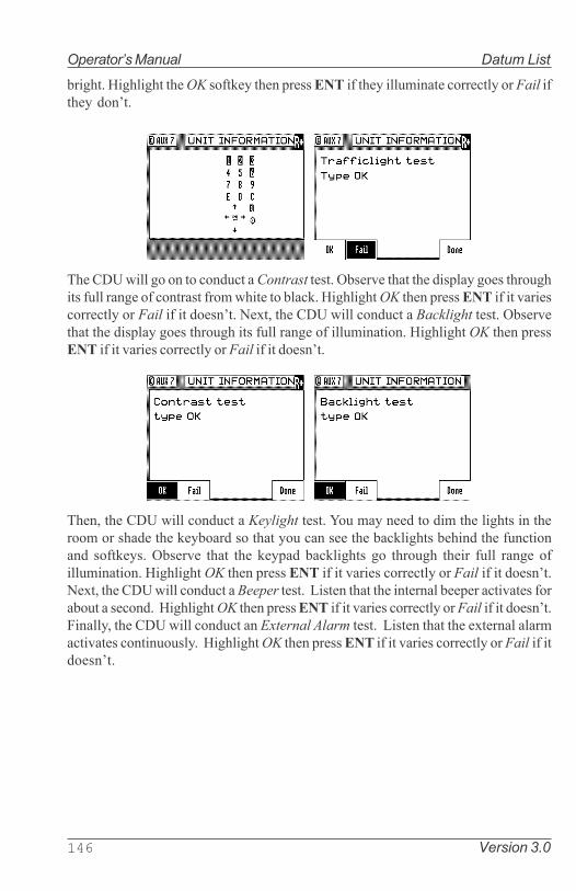
146 Version 3.0
Operator�s Manual Datum List
bright. Highlight the OK softkey then press ENT if they illuminate correctly or Fail if
they don�t.
The CDU will go on to conduct a Contrast test. Observe that the display goes through
its full range of contrast from white to black. Highlight OK then press ENT if it varies
correctly or Fail if it doesn�t. Next, the CDU will conduct a Backlight test. Observe
that the display goes through its full range of illumination. Highlight OK then press
ENT if it varies correctly or Fail if it doesn�t.
Then, the CDU will conduct a Keylight test. You may need to dim the lights in the
room or shade the keyboard so that you can see the backlights behind the function
and softkeys. Observe that the keypad backlights go through their full range of
illumination. Highlight OK then press ENT if it varies correctly or Fail if it doesn�t.
Next, the CDU will conduct a Beeper test. Listen that the internal beeper activates for
about a second. Highlight OK then press ENT if it varies correctly or Fail if it doesn�t.
Finally, the CDU will conduct an External Alarm test. Listen that the external alarm
activates continuously. Highlight OK then press ENT if it varies correctly or Fail if it
doesn�t.

Version 3.0 147
Datum List Operator�s Manual
Upon completion of the above tests, a Test Results screen will be displayed. In
addition to the visual tests which you witnessed, the CDU also performs background
tests on the program memory (FLASH ROM), the real-time Clock, and the Serial
(NMEA) Ports. These tests check about 90% of the CDU. The items which it does not
check are the GPS and Beacon receivers in the antenna.
If one of the background tests fail, you can try clearing the CDU�s memory to see if the
problem will clear. However, when you clear the memory (also known as a Cold Start),
you will erase all waypoints and configuration settings. A cold start sets the CDU
back to factory default settings. It is highly recommended to save the database into
a USB memory stick prior to doing the cold start procedure.
Otherwise, record the failure(s) and contact your dealer or MX MARINE-SIMRAD to
arrange for service or repairs. It is possible, but unlikely, that a cold start will correct
other failures noted during the selftest. MX MARINE-SIMRAD will need the CDU
serial number (from the rear panel) and the Software Version number to help you
further.
Press the EDIT key when you are finished viewing the results.
CDU Cold Start - Clearing Memory to Factory Default
A cold start sets the CDU back to factory default settings. Perform this procedure if
the CDU becomes non-responsive, fails one of the self tests described above, or
starts acting very unusually. When you Cold Start the CDU, it will erase all of
waypoints, routes and configuration settings.

148 Version 3.0
Operator�s Manual Datum List
To perform the cold start:
1. Turn the CDU off. There are three methods you can use:
A) Press the On/Off function key and highlight the Yes softkey then press
ENT. This causes a software shut down of the CDU.
B) Press and hold the On/Off function key for up to 5 seconds, this causes
a hardware shut down of the CDU.
C) Turn power off at the circuit breaker panel feed or power supply which
feeds the CDU. This is the preferred method.
2. Hold the CLR button down while applying power to the CDU; continue
holding the button until you hear a normal key click for the softkey.
3. Release the button.
4. Press the POS function key. If the position reads N 00° 00.0000, W 000°00.0000, then the CDU was properly reset. If it does not, try the procedure
again.
A common source of memory corruption is when the Lithium memory back-up battery
gets depleted. This will result in either a slow deterioration of memory retention or it
may abruptly dump all its memory.
It is recommends the battery be changed every 2 to 3 years of operation by an
authorized technical dealer. Marine electronics dealers or radio shops will typically
stock the replacement Lithium battery, type TL-5902, 3.6V (1/2 AA).

Version 3.0 149
Datum List Operator�s Manual
GPS - GPS CDU Troubleshooting
GPS3 - Visible Satellite Information
This screen provides some basic information about the MX Marine-SIMRAD smart
GPS antenna performance, in that it is basically an extension of GPS1 screen. It tells
you what satellites are available to track at the moment under the PRN number. The
signal strength of satellites under track is in the second column labeled S/N. The
weakest signal strength that the GPS receiver can track is 25. However, any satellite
with a signal strength under 32 is considered troubled, and the GPS receiver will not
use that satellite in the navigation solution. Troubled satellites tend to cause position
jumps and greatly reduce the accuracy of the GPS position fix.
The EL, AZ, and STA values represent the satellite�s Elevation and Azimuth, and
Almanac Status respectively.
Low signal to noise (S/N) quality numbers may be an indication of local interference
from on-board electronic equipment such as Radar, INMARSAT, VHF, SSB and other
high power transmitters. Review the installation of the entire system to ensure you
have followed proper procedures for cabling, power, and, most importantly, ground-
ing and antenna placement. The majority of these problems will be resolved by better
grounding and antenna location selection. Regarding grounding, the water intake for
the engine, or any other electrical ground relying on the engine or generator for Earth
ground, is not good for the GPS and especially the beacon receiver.

150 Version 3.0
Operator�s Manual Datum List
GPS4 - GPS Position Uncertainty
This screen presents a bar graph representing the HDOP for the past 23 hours. If you
are trying to do precision work or navigation in the same general area (within 100
miles) as the day before, you can look at this screen to see when the best HDOP
periods are. The GPS constellation shifts back 4 minutes per day. That means you can
expect the GPS coverage to be virtually the same today as it was yesterday.
The small 1 hour gap in the bar graph represents the 24th hour. The gap is provided to
ease the readability of the bar graph for the present time. The dashed line extending
horizontally from the 4 represents the current HDOP Limit Alarm, which is set in CFG
Position. The current HDOP and VDOP values are given in the upper window.
Antenna Reset Tools
Special tools are available in the MX51x CDU that can be used to reset the GPS and
Beacon engines in the smart antenna. Use them only in extreme cases when the GPS
or beacon receiver fails or takes too long to lock-on. The �MX Ant Reset� softkey will
clear the satellite almanac memory of the GPS engine and reset all settings of the
antenna to factory default conditions. The �CSI Reset� softkey resets the differential
beacon board.
Antenna Reset Procedure:
This procedure will work only under Engineering level mode.
1. Press the AUX key several times to bring up the AUX7 screen.
2. Press the EDIT key to bring up the softkeys.
3. Press the �#1� or �NAV� button 3 times (to bring-up Eng�g level 3).
4. Highlight the �MX Ant Reset� softkey then press ENT to reset the GPS engine
(or the �CSI Reset� softkey to reset the beacon engine).
5. Press the EDIT key to exit.
6. Press the GPS key to display the GPS or DGPS Status screen.
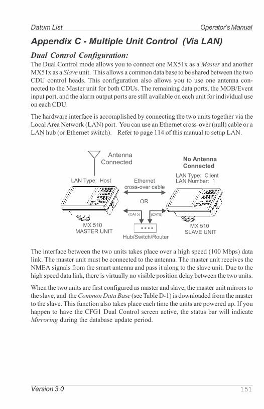
Version 3.0 151
Datum List Operator�s Manual
Appendix C - Multiple Unit Control (Via LAN)
Dual Control Configuration:The Dual Control mode allows you to connect one MX51x as a Master and another
MX51x as a Slave unit. This allows a common data base to be shared between the two
CDU control heads. This configuration also allows you to use one antenna con-
nected to the Master unit for both CDUs. The remaining data ports, the MOB/Event
input port, and the alarm output ports are still available on each unit for individual use
on each CDU.
The hardware interface is accomplished by connecting the two units together via the
Local Area Network (LAN) port. You can use an Ethernet cross-over (null) cable or a
LAN hub (or Ethernet switch). Refer to page 114 of this manual to setup LAN.
����������� ��
����������� ��
�������������������������������������� �!������"�!���
#!���$�%�!�#& ��
'�
�� ()��#"(�����!
*���+ *���+
�����������
�������
The interface between the two units takes place over a high speed (100 Mbps) data
link. The master unit must be connected to the antenna. The master unit receives the
NMEA signals from the smart antenna and pass it along to the slave unit. Due to the
high speed data link, there is virtually no visible position delay between the two units.
When the two units are first configured as master and slave, the master unit mirrors to
the slave, and the Common Data Base (see Table D-1) is downloaded from the master
to the slave. This function also takes place each time the units are powered up. If you
happen to have the CFG1 Dual Control screen active, the status bar will indicate
Mirroring during the database update period.

152 Version 3.0
Operator�s Manual Datum List
Table D-1. Master/Slave Common Database
� � �� �� ��������
�� � ����������� ����� ���� �� ��� ����
��� � ����� ���� �� ��� ������������ ������! ���� ����
������!������
���
"�� � #�� ��� �����������$ ��!��% ������� �%�& ����� �
'� ������ #�� ��� �����������$ ��!��% ������� �%�& ����� �
" � ��(�) #�� ��� �����������$ ��!��% ������� �%�& ����� �
�*�+�+ �� #�� ��� �����������$ ��!��% ������� �%�& ����� �
����,�������-�����
.���#& ��/���� #�� ��� �����������$ ��!��% ������� �%�& ����� �
The items detailed in Table D-2 are independently controlled at the individual CDU
heads.
Table D-2. Independently Controlled Functions
� � �� �� ��������
����� ��+ �� �&�%�� ������� �
*�+�)�%�� ���%
������
��������������� �
����,�������+ �� -0����� ������� �
1�%!���%�+ �� ��� ������� �
�*�+������� ��2���&
� 3� �����! �����������
������� �4
*�+������� ��2���& �� 3� �����!
������������������ �4
.)-�#� ����� ��#���
'� ������+�����%
Turning Master or Slave Units Off
Before turning the power off to either the master or slave unit(s), it is recommended
that the dual control function be disabled first. If not, the unit that remains on will
alarm until the data link is re-established, the unit is turned off, or Dual Control is
turned off.

Version 3.0 153
Datum List Operator�s Manual
Backup Receiver Integrity Monitoring (BRIM)
BRIM is a fault-detection and recovery algorythm in the MX51x software that com-
pares position solutions between two independent systems. Whoever has the best
accuracy becomes the unit in control. The basic requirements are; they are both
MX51x models with its own GPS/DGPS smart antenna and both have the IM option
enabled.
This IM feature can be found under the CFG/Dual Control menu in units that has the
IM license. This menu item is normally hidden and will show only when another
MX51x unit has been detected.
����������� ��
����������� ��
�������������������������������
������� �!������"�!���#!���$�%�!�#& ��
'�
�� ()��#"(�����!
*���+ *���+
Multiple Unit Control Configuration:
The Multiple Unit Control mode allows you to connect one MX51x as a Master, up to
two MX51x as the Slave units, and up to three MX51x as the Repeater units. The
Repeater unit, however, only acts as a display unit. It has no capability to modify any
setting unless a password (set by the Master unit in CFG1/Security) is entered. The
Multiple Unit Control system must have a minimum of three MX51x and a maximum of
five MX51x units altogether (see Table D-3). The system must have one Master and
at least one Slave. This allows a common data base to be shared among the CDU
control heads. This configuration also allows you to use one antenna connected to
the Master unit for all CDUs. The remaining data ports, the MOB/Event input port,
and the alarm output ports are still available on each unit for individual use on each
CDU. This feature can be enabled in the CFG Dual Control menu.
The hardware interface is accomplished by connecting the units together via an
Ethernet switch (or hub). Refer to page 115 of this manual to setup LAN.

154 Version 3.0
Operator�s Manual Datum List
����,
-�)�!�.������/&�&����!0&#�
�,�1��'2�31�-������,�1���&!�����
�4$5�����1
����4$5�����1
-�)�!�.������/&�&����!0&#�
����� ��
����� ���6�
�� ()��#"(�����!
����4$5�����1
-�)�!�.������/&�&����!0&#�
����� ���67
����4$5�����1
-�)�!�.������/&�&����!0&#�
����4$5�����1
-�)�!�.������/&�&����!0&#�
��-����� ���6�
��-����
� ���67
����/��&!��������&� ���
����,
����, ����,
����,
The interface among the units takes place over a high speed (100
Mbps) data link. The master unit must be connected to the antenna.
The master unit receives the NMEA signals from an MX antenna and
pass it along to the slave and repeater units at a one second rate. Due
to the high speed data link, there is virtually no visible position delay
among the units.
When the units are first configured as master, slave, and repeater, the
master unit mirrors to the slaves and repeaters, and the Common Data
Base (see Table D-1) is downloaded from the master to the slaves and
repeaters. This function also takes place each time the units are pow-
ered up. If you happen to have the CFG1 Dual Control screen active,
the status bar will indicate Mirroring during the database update pe-
riod.
The Table D-3 below shows all the possibilities in the Multiple Unit
Control system.

Version 3.0 155
Datum List Operator�s Manual
Table D-3. Multiple Unit Control Configuration
� ��� �� ��
�
���� ��
�������������� �!�"�� � �
� � �
� � �
� � �
� � �
� � �

156 Version 3.0
Operator�s Manual Datum List

Version 3.0 157
Datum List Operator�s Manual
Appendix D - Demonstration Mode
This enables the CDU to function as though you are under way, even though you are
completely stationary. The default setting is No. When set to Yes, all three Traffic
Lights will be illuminated, and a D symbol is displayed in the upper left corner of every
display. Generally speaking, this feature is used by SIMRAD and dealers for show
room or trade show demonstrations. However, you can use it as a training tool until
you become familiar with the CDU. You can also use it to output NMEA 0183 records
on the data ports to test other devices such as autopilots, chart plotters, and radars.
In the CFG Operation screen, activate the Demonstration Mode by selecting Yes.
Follow:
Active Route: causes the CDU to use the route loaded in RTE1
screen.
Rhumb Line: causes the CDU to follow the bearing you input in
this screen under Demonstration COG.
Demonstration SOG: causes the CDU to simulate a speed of up to 99
knots. Slower speeds of 5 to 25 knots provide the best demonstra-
tion results.
Demonstration COG: causes the CDU to simulate a course over ground
of up to 359.9 degrees when Follow is set to Rhumb Line.
To setup your course, load the desired waypoints into RTE1. Notice
that the CDU loads your point of departure as N 00, W 000.

158 Version 3.0
Operator�s Manual Datum List
Before you adjust your position, set your WPT Pass Criterion to Distance in the
CFG1 Navigation screen. To adjust your position, pick a point near your first
waypoint. A distance of 1or 2 miles from the first waypoint is good to start with. Go to
the POS1 screen and press EDIT.
Next, press the NAV function key, then the E key. Press the Reset XTE softkey. Press
the EDIT key. This resets your cross-track error and updates the active route in RTE1
with the adjusted position.
Now just use the CDU as you normally would. You can output NMEA 0183 data
records to other devices. Be careful, however, other instruments will interpret the
data as completely valid. So, don�t run the Demonstration Mode while you are
underway and connected to devices that are being used in real time navigation, like
the autopilot.

Installation Manual List of Components
160 Version 3.0
APPENDIX F-
MX51x INSTALLATION SECTION

List of Components Installation Manual
Version 3.0 161
Notes:

Installation Manual List of Components
162 Version 3.0
SECTION 1
LIST OF COMPONENTS

List of Components Installation Manual
Version 3.0 163
List of Components
Table 1.0 Standard Parts for MX 510 Model

Installation Manual List of Components
164 Version 3.0
Table 2.0 Standard Parts for MX 512 Model

List of Components Installation Manual
Version 3.0 165
Table 1.1 Smart Antenna Selection Chart
Table 1.2 Antenna Cable Assembly Selection Chart

Installation ManualTechnical Specifications
Version 3.0 165
SECTION 2
TECHNICAL SPECIFICATIONS

Installation Manual Technical Specifications
166 Version 3.0
MX51x Control and Display Unit (CDU)
Display:
Pixels: 6.4 nch, 1/4 VGA 320 x 240
LCD: Black and White STN. Matches polarized sun
glasses.
Viewing dir.: 6 O�clock.
Back light: CCFL
Keyboard:
Type: Tactile silicone rubber
Contact: Carbon
Back light: Yellow LEDs
Front enclosure:
Plastic: Black ABS/Plastic
Back enclosure:
Plastic: Black ABS/Plastic with EMI conductive spray
Connectors:
Power/Data: 12-Pin Male (LTW)
Antenna: 10-Pin Female (LTW)
AUX : 8-Pin Female (LTW)
LAN : RJ-45
Rear USB: USB 2.0
Front USB: USB 2.0
For MX512 model (Only)
VGA : 15 Pin D-Conn.
Multi-Port NMEA : 44-Pin D-Conn.
Cables:
Power/Data: 12-wire (Female Connector), 3 meters
Auxiliary: 8-wire (Female connector), 3 meters
Antenna: 10-Wire (F-F 10-Pin LTW connectors) cable
Antenna Cable Lengths: 3, 20, 40, 60 or 80 meters (order as
needed)
LAN Crossover Cable: 2 meters RJ-45 cable Asssembly
For MX512 model (Only)
VGA Cable: 2 meter with 15-Pin D-connectors
44-Pin Multi-NMEA Cable: 2 meter with 44-Pin connector and
44-Pin in-line connector

Installation ManualTechnical Specifications
Version 3.0 167
MX Series Smart D/GPS Antenna
Receiver GPS:Type: L1, C/ A Code, 12 channel
continues tracking
Update rate: Once per second
Accuracy: <2 m 2DRMS Position with DGPS
<5 m 2DRMS without correction
Dynamics: Velocity: 460 m/ s
Acceleration: 2.5g
Time to first fix: Less than 1 minute with almanac
15 minutes from coldstart.
Reacquisition: 15 seconds typical
DGPS Input: RTCM SC- 104 format, from
internal beacon receiver.
Differential Correction
Beacon:
Type: 2 channels, Automatic or Manual
tuning
Frequency: 283.5 - 325 KHz, in 500 Hz steps
Dynamic Range: 100dB
Adjacent Channel Rejection: 40dB (500 Hz)
Bit rate: 25, 50,100, or 200 (auto- sync)
RTCM Messages Supported: Type 1, 2, 3, 5, 7, 9,16
SBAS: WAAS, EGNOS, MTSAT
Physical
MX51x CDU:Height: 150 mm
Width: 292 mm
Depth overall: 105.6 mm
Depth flush mounted: 32.9 mm (to wall)
Depth for cables: 150 mm.
Weight: 2.0 lbs.
MX521 Antenna:
Height: 89 mm.
Diameter: 182 mm.
Cable: Choose from 3, 20, 40, 60 or 80 m
Weight: 1.9 lbs.

Installation Manual Technical Specifications
168 Version 3.0
Environmental
MX51x CDU Console:
Operating Temperature: -15 to +55 °C. IEC/EN 60945 Ed. 4
Storage Temperature: -30 to +70 °C. IEC/EN 60945 Ed. 4
Humidity: IEC/EN 60945 Ed. 4
Vibration: IEC/EN 60945 Ed. 4
Corrosion: IEC/EN 60945 Ed. 4
EMI: IEC/EN 60945 Ed. 4
Water Resistance: IPC 65
IMO: MSC 112 (73), IEC 61108-1, IEC
61162-1, IEC 60945 Ed. 4
FCC: Part 15, Subpart B, Class B
Compass Safe Distance: > 1 m. (Recommended)
Power:
MX51x CDU :
Power Supply Type: DC/ DC switch mode with galvanic
separation
Consumption: <11W (display back light on). Typi-
cal 8W at 24 volt external supply
voltage. Typical 8.7W at 12 volt
external supply voltage
Supply voltage: 10.5 to 32 VDC
Reverse protection: -100 volt: internal diode
Over voltage protection: +40 volt: fuse and transient voltage
suppression
Fuse: Internal over current / over tempera-
ture fuse. Automatic resetting
Insulation: Supply voltage to data pins or shield:
Maximum 50 VDC
Antenna supply: 12 VDC, @ 500mA
MX Antennas:MX 421B: 12 VDC, 280 mA
MX 521A: 12 VDC, 200 mA
MX 525A: 12 VDC, 200 mA

Installation ManualTechnical Specifications
Version 3.0 169
MX51x CDU Inputs and Outputs:
The input and output circuits of the serial interfaces meet the require-
ments of:
� NMEA 0183 version 1.5, 2.0, 2.1, 2.2 & 2.3
� IEC 61162-1 including the requirements of ITU-T V.11.
NMEA talker (all outputs):
Levels: Maximum ±6 volt, minimum ±2
volt, A out relative to B out
Current: Minimum 15mA
Protection: -1 volt to +6 volt, output relative to
shield, ±50 volt, output relative to
external power lines
NMEA listeners (all inputs):
Insulation: Opto-coupler. Maximum ±50 volt,
input relative to shield or power
supply lines
Impedance: Minimum 500 Ohms, A- in relative
to B- in
Threshold: Maximum 2 volt and 2 mA
Protection: ±15 volt, A- in relative to B- in, ±50
volt
LAN
Protocol: NMEA over TCP/IP, MX proprietary
messages
Connector: RJ-45
MOB/ Event input
Insulation: Maximum ±50 volt, input relative to
power supply lines
Impedance: 3.5 kOhm input relative to Refer-
ence GND
Pull-up: 15 kOhm to internal 12 volt
Threshold: Positive going maximum 2.3 volt,
input relative to Reference GND
Negative going minimum 0.6 volt,
input relative to Reference GND
Hysteresis minimum 0.6 volt
Protection: ±25 volt, input relative to shield
±50 volt, input relative to external
power lines

Installation Manual Technical Specifications
170 Version 3.0
Frequency: Triggered with 50 mS bounce
control
Pulse width: Minimum 100 mS
Alarm output
Dry Contact: Normally Open, when not in Alarm
state, or after acknowledgement.
Closed to Ref. GND, when in Alarm
On state.
Antenna voltage output
DC voltage: 12 VDC, +1.0 VDC loaded; (11.5
VDC nominal unloaded)
DC current: 500 mA @ 12.0 volt DC
Speed Log Pulse Input/output
DC voltage: 0-12 VDC, pulses
Number of pulses: 100-500 selectable

Installation Notes
Version 3.0 171
Installation Manual
SECTION 3
INSTALLATION NOTES

Installation Manual Installation Notes
172 Version 3.0
GENERAL
The MX51x Control and Display Unit (CDU) is splashproof and can be installedboth above and below deck. To flush mount, use the optional flush mountbracket. Ensure that the navigator is mounted in a dry place or where waterflows off easily. Avoid places where water may accumulate for any period oftime.
Electronic ConnectionsRefer to figures in Section 4 for the mechanical drawings of the display consoleand Section 5 for the electrical interface cables.
The MX510 has five connectors at the back, namely;
� Power/Data Connector (12-Pin)
� Antenna Connector (10-Pin)
� Auxiliary Connector (8-Pin)
� RJ-45 LAN Connector
� Rear USB 2.0 Connector
The MX512 has all the five connectors of the MX510 plus a 44-Pin Data I/O and15-Pin VGA connectors. The NMEA port #5 through #11 is accessible throughthe Data I/O connector.
���������� �
���������� ���������������
��������������� ���!"
��#�$��%��&�'���(��� ������������
��#�$��%��&�'�)����������������
�#�$��%*�&�')!�$&$��+����������
,-#��.)����������
The PWR/DATA and AUX cables are standard accessories included inthe kit. The LAN, USB and antenna cables are optional items that canbe ordered separately. Specify the proper antenna cable length whenordering.

Installation Notes
Version 3.0 173
Installation Manual
Wire Preparation Procedure
PWR/DATA Cable (6-Pairs Twisted):
We recommend that the main cable insulation (black plastic) be stripped about5 inches back to expose the color-coded leads. Below are the color and signaldesignation of the wires:
Pin 1 --- Red ----------- +10-32 VDC
Pin 2 --- Black -------- Negative GND.
Pin 3 --- Blue ------- NMEA TX1-
Pin 4 --- Brown ------- NMEA TX1+
Pin 5 --- Orange --------- NMEA RX1-
Pin 6 --- Green ------ NMEA RX1+
Pin 7 --- Yellow -------- NMEA TX2 -
Pin 8 --- White ------- NMEA TX2+
Pin 9 --- Purple ---- NMEA RX2-
Pin 10 -- Grey ------ NMEA RX2+
Pin 11 -- Lite Green -- GND Fast Channel IN
Pin 12 ------------ GND
Strip the individual wire insulation about 1/2 inch to make it more convenient toconnect the wires to a terminal strip posts. Use electrical tape or shrink tubingto protect exposed shield wires. Use a 20-position terminal strip to terminatethe PWR/DATA and AUXiliary cables. This item is not supplied with the prod-uct.
AUX Cable (4-Pairs twisted):
Below are the color and signal designation of the wires:Pin 1 --- Yellow ------- Ext. MOB Input
Pin 2 --- Green -------- GND.
Pin 3 --- Blue ----------- Dry Contact 1
Pin 4 --- Purple -------- Dry contact 2
Pin 5 --- Grey ----------- Speed Log IN +
Pin 6 --- White --------- Speed Log IN -
Pin 7 --- Orange ------- Speed Log Out +
Pin 8 --- Brown --------- Speed Log Out -
Note: An optional Junction Box (P/N 500 100 1002) is available for
easy plug & play installation. This junction box has all the three cables
(Pwr/Data, Aux and Antenna) pre-installed.

Installation Manual Installation Notes
174 Version 3.0
External Power
The MX51x will to operate on 12 ~ 32 VDC supply. It can tolerate volt-ages no lower than 10 volts and no higher than 35 volts. It draws about 1Ampere at 12 VDC (with the antenna connected). Power wire colors arered (+) and black (-). Even though the navigator has a reverse polarityprotection device, we recommend that the installer observe proper polar-ity before hooking up the power leads. Use a 2 amp. fuse in line with thered wire.
Navigator Grounding
The internal electronic circuits of the navigator are isolated from theexternal power supply. Connect the ground stud to ship�s seawater groundto avoid static charge build up.
Note : �Seawater ground� is any electrically conductive
material that is directly in contact with sea water.
ANTENNA INSTALLATION
Antenna Location
The MX series smart antennas (MX421, MX521, MX575 & MGL3) aredesigned for exposed installation. They should be mounted with a rela-tive clear view of the horizon. Do not, mount the antenna on top of a verytall mast, as this may degrade the COG and SOG calculations, particu-larly when in DGPS mode. Ensure the antenna is placed outside thebeam path of transmitting radar (typically +15° horizontally from thearray�s center point) and INMARSAT satcom (A, B, C, or M; typically+10° from the array�s center point in any of the possible transmittingdirections and at least 5 meters from any side lobe or back lobe direc-tion). The GPS antenna should be mounted below and at least 5 metersaway from these types of antennas. Do not place it within 3 meters of aSSB or VHF radios or their antennas.
Antenna Options
Four antenna models can be used with the MX51x, namely:
� MX421 D/GPS smart antenna
� MX521A D/GPS smart antenna
� MX525A D/GPS Sensor
� MX575A Satellite Compass
Wiring hookup to the MX421, MX521A, and MX525A antenna models

Installation Notes
Version 3.0 175
Installation Manual
are the same. The 12 VDC drive voltage to the antenna is normally
provided by the MX51x CDU.
Antenna Connector
The 10-pin connector at the bottom of the antenna housing provides the
necessary interfacing between the smart antenna and the MX51x CDU.
Refer to the MX antenna wiring diagram shown in Appendix G - Section
4 of this manual.
�������������� �������� �
������� ��������������� ������� ��������������
�
����
� � �����!"��
�����!"��
��������
"��
��������#
!"��
�#$%�
�&'($!����������� �
� )(! ��������������
* #$+ ������������������ ��!�" ��#!
� #), ������������������ ��!�" ���!
� -)" �$�%����#!
. "), �$�%�����!
/ 0($&��'� �$�����
%����#!()���" ��#!
&��'� �$�����
%����#!
1 �&2&��'� �$�����
%�����!()���" ���!
&��'� �$�����
%�����!
3 �)�$ ����$���!
���)�$�
")0����$��#!
&��'� �$�����
%����#!
&��'� �$�����
%�����!
()���" ���!
()���" ��#!
()���" ���!
()���" ��#!
Note: For MX575 connection, please refer to the MX575 Installation &
Operation Manual.
Antenna Cable Options
The MX smart antenna does not come standard with an antenna cable
assembly . The dealer/installer has to determine the length required
and order the appropriate cable length. The following cable sizes are
available:
� 3 M, Antenna Cable (with 2 connectors) -- P/N 500 100 1008
� 20 M, Antenna Cable (with 2 connectors) -- P/N 500 100 1006
� 40 M, Antenna Cable (with 2 connectors) -- P/N 500 100 1007
� 60 M, Antenna Cable (with 1 connector) -- P/N 3508 102 70640
� 80 M, Antenna Cable (with 1 connector) -- P/N 3508 102 70185

Installation Manual Installation Notes
176 Version 3.0
External Differential Connection
Differential corrections from an external beacon receiver can beconnected to either the MX421-10 (GPS only) or the MX521A/MX525AD/GPS models. RTCM connections are done directly to the antennacable;
MX421 (GPS only) antenna -- Pins 7 (yellow) and 8 (white)
MX521A/MX525A antenna ---- Pins 9 (purple) and 10 (grey)
The MX series antennas are compatible with the standard RTCM SC-104 signal. Baud rate speed of 4800 is the default requirement,however, other RTCM speeds (at 2400, 9600, or 19200) may also beused. This can be selected in the MX51x under the CFG => DGPSmenu.
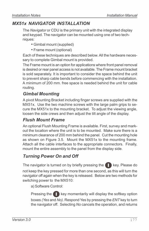
Installation Notes
Version 3.0 177
Installation Manual
MX51x NAVIGATOR INSTALLATION
The Navigator or CDU is the primary unit with the integrated displayand keypad. The navigator can be mounted using one of two tech-niques:
� Gimbal mount (supplied)
� Frame mount (optional)
Each of these techniques are described below. All the hardware neces-sary to complete Gimbal mount is provided.
The Frame mount is an option for applications where front panel removalis desired or rear panel access is not available. The Frame mount bracketis sold separately. It is important to consider the space behind the unitto prevent sharp cable bends before commencing with the installation.A minimum of 200 mm. free space is needed behind the unit for cablerouting.
Gimbal Mounting
A pivot Mounting Bracket including finger screws are supplied with theMX51x. Use the two machine screws with the large palm grips to se-cure the MX51x to the mounting bracket. To adjust the viewing angle,loosen the side crews and then adjust the tilt angle of the display.
Flush Mount Frame
An optional Flush Mounting Frame is available. First, survey and mark-out the location where the unit is to be mounted. Make sure there is aminimum clearance of 200 mm behind the panel. Cut the mounting holeas shown on Figure 3.5. Mount the MX51x to the mounting frame.Attach all the cable interfaces to the appropriate connectors. Finally,mount the entire assembly to the panel from the display side.
Turning Power On and Off
The navigator is turned on by briefly pressing the key. Please do
not keep the key pressed for more than one second, as this will turn thenavigator off again when the key is released. Below are two methods for
switching power to the MX510:
a) Software Control:
Pressing the key momentarily will display the softkey option
boxes (Yes and No). Respond Yes by pressing the ENT key to turnthe navigator off. Selecting No cancels the operation, and returns

Installation Manual Installation Notes
178 Version 3.0
the unit to normal operation.
b) Hardware Control:
Pressing the key for more than 3 seconds, turns the power off
under hardware control. The MX51x can not be turned on again for10 seconds when this method is used. Attempting to turn the uniton during this 10 second period, will only activate the navigator foras long as the key is not released. This option is not normallyused, and is provided as an emergency alternative to the softwarepower control.
If the external power to the unit fails for any reason, the navigatorwill remember if it was on or off for about 20 minutes. That is if thenavigator was on when the power failed and the power comes backwithin 20 minutes, the navigator will turn itself on again. Otherwise,
it will stay turned off until the key is pressed.
EQUIPMENT INTERFACING
Introduction
The MX510 has two user NMEA ports while the MX512 has eleven. Anyof these data ports can be used to communicate with other externalequipment using the standard NMEA 0183 protocol. All NMEA interfaceports are configured for RS-422 standard. This configuration complieswith all NMEA 0183 hardware versions. The RS-422 electrical interfacewill almost always work with the older NMEA 0183 version 1.5 electricalinterface; both of which are balanced line interfaces. If for some reasonyou can�t get this interface to work, use an RS232 -to-RS422 interfaceconverter.
Other features available from the MX51x are:
� External Man-Over-Board (MOB) switch input (also used
for quick save of waypoint)
� Pulse speed log input
� Pulsed speed log output
� External alarm
� Compass row displays (when connected to an MX575
GPS Compass)Refer to Appendix G - Section 4 of this manual for wiring
information.

Installation Notes
Version 3.0 179
Installation Manual
External Man Over Board & Event
An external push button (normally open) switch can be connected be-tween the pin 1 (MOB/Event) input and REF GND of the AUX cable toactivate the MOB/Mark function.
The Man-Over-Board (MOB) function is activated when the external switchis pressed and held for 3 seconds. Once activated, the MOB conditioncan only be canceled from the MX510 front panel display. Refer to theOperation section of the manual for this operation and more details onthe Man Over Board function. When this switch is pressed for 1 second,this causes your present position and time to be stored as a waypoint inthe waypoint bank. A message indicating which waypoint number isused will be displayed on the MX51x screen for up to 5 seconds.
Speed Over Ground Pulse Output
The MX51x can output the GPS calculated speed over ground in a pulseformat.
The pulse output is derived from pins 7 (orange) & 2 (green) of the AUXcable. The speed log out (+) is the orange wire, while the speed log (-)is on the green wire. It is a 0-12 Volt signal pulse.
To setup the MX51x speed pulse output, press the CFG key then scrolldown to Log Pulses menu. Press the E key, then press the ENT key tochange the Emulation enabled to Yes (default value is No). This menualso controls the number of pulses per nautical mile (200 is the pre-selected value). Press the E key when you are done with editing.

Installation Manual Installation Notes
180 Version 3.0
External Alarm Output
The MX510 Ext. alarm output connection is on pins 3 and 4 of the AUX(8-pin) cable. They are held open (floating) during normal operations. Inan alarm condition, the external alarm pin is switched to ground poten-tial. When an alarm condition is cleared or acknowledged, the Ext.alarm signal will return to open condition automatically (refer to tablebelow for relay conditions). However, it is possible to retain the externalalarm condition by setting the �Retain external alarm:� to ON under theCFG1/Operation menu. At this setting, the external alarm signal canonly be cleared by correcting the problem.
(4��� ����)� �5�� 6��� � �
�*��*��� ���%++ � , ���-���
�*��*�)� ���%� �
����./�0!�����, ���-���
�*��*�)� ���% �
�1��2�./�0! �, ���-���
�������" ������3��
+��/���, ���-���
�
The external alarm is derived from the �EXT alarm� port on AUX cable,pin 3 (Blu) and pin 4 (Prpl). The software is setup in each of the appro-priate CFG1 (Alarms) menu. The relay coil supply voltage must beconnected to an independent battery backed-up alarm supply. Makesure the relay coil voltage is compatible with the voltage rating of thealarm power supply (i.e. NTE Electronics Relay - P/N R14-11D10-12 foruse in a 12 VDC supply). The negative ground of the alarm power sup-ply must be connected to Pin 3 (Blu) of the AUX (8-pin) cable (refer tothe relay diagram below).

Installation Notes
Version 3.0 181
Installation Manual
NMEA Interface
The MX51x meets the NMEA 0183 version 2.3 electrical standard formarine interface communications with other marine equipment, suchas: Radars, Plotters, Autopilots, Fish Finders, etc.
There are differences in the electrical interface specification betweenNMEA 0183 version 1.5 (introduced in 1987) and NMEA 0183 version2.0 and later (introduced in 1994). Some older model equipment utilizeRS-232, others use RS-422, and others meet the older version 1.5 speci-
fication.
NMEA Interface to other Equipment
The MX51x complies with the NMEA 0183 V2.3 protocol. As versionV2.1 is not necessarily compatible with the older version V1.5, the dif-ferences in hardware are mentioned here to avoid possible conflicts:
Listener:
The listener input works with a threshold of 2 volts compared to theformer 4 volt. It is still an insulated input and, in general, there should notbe any interface problems receiving data from the olderstandard.
Talker:The talker output is a RS-422 output:NMEA talker output B is active compared to GND or shield of the naviga-tor. In the old version, output B was normally tied to GND or shield.
The maximum drive voltage between the talker A and B outputs is ±6volt.
Compared to the former 0 to 15 volt output, the negative voltage
between the talker A and B output may be a problem on older
listeners which do not meet the new standard.
The minimum output voltage may be as low as ±2 volt. This is not
compatible with the former 4 volt input threshold and may be the cause
of interface problems. If this is the case, try using an RS-232 to RS-422convertor to interface with the MX510. This may more likely solve theproblem. Otherwise third party conversion boxes may be necessary.
Cables provided for the NMEA signals are shielded pairs. If extensioncables are needed, be sure to use similar shielded pair cables in orderto avoid spurious signal radiation. More than one NMEA listener can beconnected in parallel to the same NMEA talker. The maximum numberof listeners connected to a single talker is dependent on the combined

Installation Manual Installation Notes
182 Version 3.0
listener input impedance�s, and the capacity available for data through-put.
MX51x NMEA 0183 Sentences
The NMEA Standard provides for asynchronous transmission, with asingle Talker and multiple Listeners per line. Typical use includes infor-mation transfer from electronic positioning and navigational devices toautopilots, plotters, terminals, printers, etc.
The NMEA 0183 Standard uses an 8 bit ASCII block oriented protocol,that is not compatible with the NMEA 0180 simple format or the NMEA0182 complex format due to differences in data format, baud rate andparity bits.
Data Format
Data are transmitted in different sentences, each containing one or moredata fields. A field consists of a string of characters immediately pre-ceded by a �,� (comma) character, except for the first (address) fieldwhich is preceded by �$�, indicating the beginning of a new record. Hex0D 0A <CR>< LF> - end of sentence - must follow the last field in eachsentence.
The data fields are identified only by their position within the sentenceas determined by the field delimiters (comma). Numerical data fieldswithin a sentence may vary in length from one sentence to another,depending on the precision available.
Data field position is therefore determined only by counting �,� (com-mas) rather than counting the total number of characters from thebeginning of the sentence.
The last data field is not followed by a comma delimiter. When achecksum is used, the last data field is followed by an asterisk �*�,indicating that the checksum follows. The checksum is the absolutevalue calculated byexclusive -OR�ing the 8 data bits (no start bits or stop bits) of eachcharacter in the sentence between, but excluding �$� and �*�. Thehexadecimal value of the most significant and least significant 4 bitsof the result are converted to two ASCII characters (0- 9, A- F) fortransmission. The most significant character is transmitted first.

Installation Notes
Version 3.0 183
Installation Manual
Example:
9���2:;););�/��;.;�<==4�,>4.?>
?$�&"����������������������������������������������
������������*$�����
06�$���&��=��51!*�%@:�'A��3��/��/�B��/�;���C!$��"�$��3����/�
�=��51!*�"�&$*$���
��$�1��D�*��1!��;��E��!�$��&�*$&�1
$����$������1����;�.E.�D�;�,E,$F=�
��F�$�!"���D�������%��!�$��&�*$&�1'
����!1�";�)&(�+1�E�)
����!1��)E ����G�&$";�3E ����$�G�&$"
�������D����������"�&$*$���
)""��11�����E�2�&5���$"���$D$�����������������������2:E����������D��*����������11#2���5�:����
NMEA Output Sentences
All sentences have the identifier �GP� for Global Positioning Systems.All position data are in the user selected (displayed) datum except forGGA where the datum can be manually set to WGS84, independent ofthe selected (displayed) datum.
RMB is transmitted only if an active route is present. Please refer to theRoute section of the Operator�s Manual for details on setting up an ac-tive route.
APA , APB , and XTE , are transmitted only if an active route is presentand the Autopilot Alarm in each of these NMEA sentence setup screensis Enabled and this feature is not in an alarm condition.
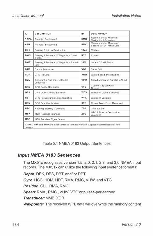
Installation Manual Installation Notes
184 Version 3.0
�� ��������� �� ���������
�� � )!��6$&������������) ���,���**��"�"��$�$*!*��G$F��$���A�D��*��$��
�� )!��6$&������������� ���,���**��"�"��$�$*!*�6��$D$�������2���1$�� ���
�� ����$�F�0�$F$����� �1�$���$�� ���� ,�!��1
��� ����$�F�B� $1���������H�+6�$���#�������$��&�
��� ,�!��1
��� ����$�F�B� $1���������H�+6�$���#�,=!*8.$��
��� .����#�����,�����!1
��� ��!*�,�D������ ��� ����B� �$D�
�� ����?$�� ��� ��� H������6��"���"�@��"$�F
��� ���F��6=$����1$�$���#�.��$�!"��.��F$�!"�
��� �6��"����1!��"�����&&�&����H$�"
��� ����,��F��,�1$"!�&1 �����!�1��B��6��"�0G�����!�"
�� ���� 0��B�)��$G������&&$��1 ��� H�+6�$����&�1!���3�&��$�+
��� �����1�!"����F����$1������$1�$�1 ��� H�+6�$���.����$��
��� ��������&&$��1�A��3$�( ��� ���11#�2���5�:����;����1!��"
��� @��"$�F������$�F���**��" �� 2$*��B� ���
��� ��I�,���$G���A����D��� ����2��B�2$*����� �1�$���$��H�+6�$��
��� ��I�,���$G����$F��&�����!1
<� � �;�������"���������&"���1��������D��*��1�%G��1$����/'���������**��"�"�D�����("�1$F�1/
Table 5.1 NMEA 0183 Output Sentences
Input NMEA 0183 Sentences
The MX51x recognizes version 1.5, 2.0, 2.1, 2.3, and 3.0 NMEA inputrecords. The MX51x can utilize the following input sentence formats:
Depth: DBK, DBS, DBT, and/ or DPT
Gyro: HCC, HDM, HDT, RMA, RMC, VHW, and VTG
Position: GLL, RMA, RMC
Speed: RMA , RMC , VHW, VTG or pulses-per-second
Transducer: MMB, XDR
Waypoints: The received WPL data will overwrite the memory content
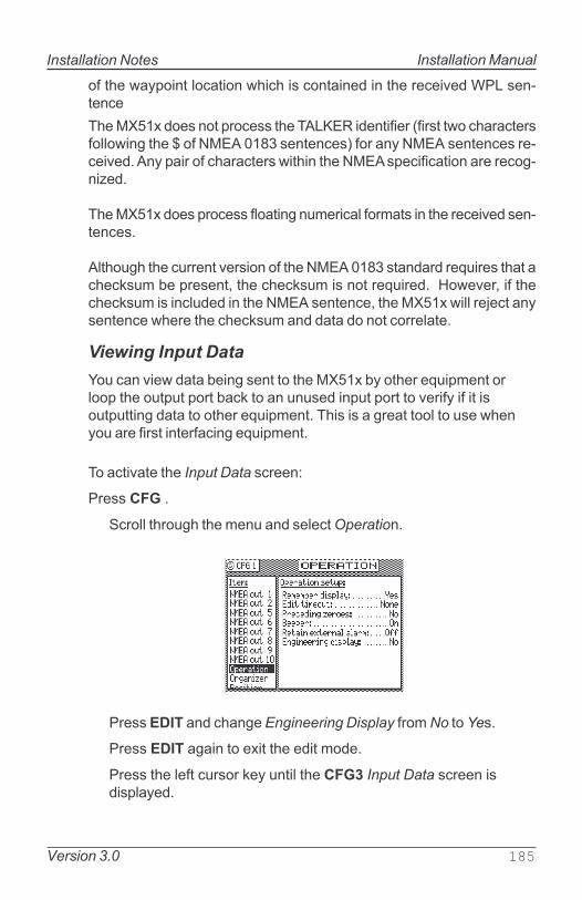
Installation Notes
Version 3.0 185
Installation Manual
of the waypoint location which is contained in the received WPL sen-tence
The MX51x does not process the TALKER identifier (first two charactersfollowing the $ of NMEA 0183 sentences) for any NMEA sentences re-ceived. Any pair of characters within the NMEA specification are recog-nized.
The MX51x does process floating numerical formats in the received sen-tences.
Although the current version of the NMEA 0183 standard requires that achecksum be present, the checksum is not required. However, if thechecksum is included in the NMEA sentence, the MX51x will reject anysentence where the checksum and data do not correlate.
Viewing Input Data
You can view data being sent to the MX51x by other equipment orloop the output port back to an unused input port to verify if it isoutputting data to other equipment. This is a great tool to use whenyou are first interfacing equipment.
To activate the Input Data screen:
Press CFG .
Scroll through the menu and select Operation.
Press EDIT and change Engineering Display from No to Yes.
Press EDIT again to exit the edit mode.
Press the left cursor key until the CFG3 Input Data screen isdisplayed.
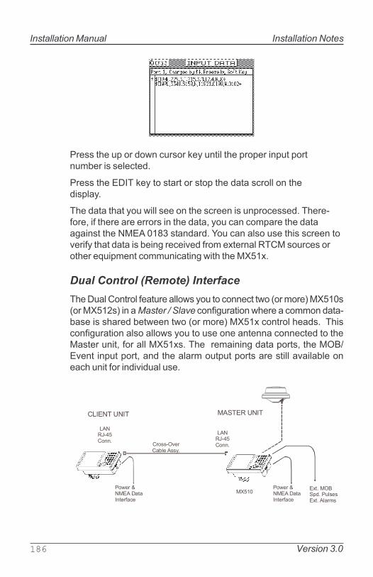
Installation Manual Installation Notes
186 Version 3.0
Press the up or down cursor key until the proper input portnumber is selected.
Press the EDIT key to start or stop the data scroll on thedisplay.
The data that you will see on the screen is unprocessed. There-fore, if there are errors in the data, you can compare the dataagainst the NMEA 0183 standard. You can also use this screen toverify that data is being received from external RTCM sources orother equipment communicating with the MX51x.
Dual Control (Remote) Interface
The Dual Control feature allows you to connect two (or more) MX510s(or MX512s) in a Master / Slave configuration where a common data-base is shared between two (or more) MX51x control heads. Thisconfiguration also allows you to use one antenna connected to theMaster unit, for all MX51xs. The remaining data ports, the MOB/Event input port, and the alarm output ports are still available oneach unit for individual use.
����:��/��0��6"/��!&1�1:��/�)&��*1
.)�,-#�����/
.)�,-#�����/
��(���B���:)� ���A����D���
���11#0G����8&��)11+/
�)�2:,���A2�.A:�2���A2
��(���B���:)� ���A����D���

Installation Notes
Version 3.0 187
Installation Manual
The hardware interface is accomplished by connecting the RJ-45connectors of the MX51x units using a crossover (null) LAN cable(for two units) or CAT5 Ethernet cables with an Ethernet switch (formore than two units). You can purchase a pre-made LAN crossovercable or CAT5 Ethernet cable assembly from MX Marine dealers oryou can make it up yourself using the diagram below.
.)�,-#�
���������
.)�,-#����������
�
�
�
�
�
�
�
�
�
�
�
�
�����)�2:,���A2
�����.)3:���A2
.)��2��7
.)��2��#
.)��,��7
��
��
���)���������������"
.)��2��#
.)��2��7
��
.)��,��7
.)��,��#
��
.)��,��#
��
��
��
��
MX51x LAN Crossover (Null) Cable Diagram
The interface between the two (or more) units takes place over a highspeed (100 Mbps) data link. The master unit must be connected to thesmart GPS antenna unit (MX421, MX521A, MX525A, or MX575A). Themaster unit receives the position data then transfer it to the slave unit(s)at a one second rate (the same as the position calculation). Due to thehigh speed data link, there is virtually no visible position delay betweenthe two (or more) units.
When two (or more) units are first configured as master and slave(s), themaster listens for a configuration polling message from the slave(s).Once the master recognizes the slave�s polling message, the Common
Data Base (see Table below) is downloaded from the master to theslave(s). This function also takes place each time the units are poweredup.

Installation Manual Installation Notes
188 Version 3.0
Table 5. Master / Slave Common Data Base
The items detailed in Table 6 are independently controlled at theindividual MX51x control heads.
Table 6. Independently Controlled Functions

Installation Notes
Version 3.0 189
Installation Manual
MX51x/BRIM (Backup Receiver with Integrity Monitoring)
Feature
The Integrity Monitoring (IM) feature allows the dual-control MX51x units toconstantly compare each GPS position solutions and, if configured to do so,give an alarm and/or automatically switch to the unit with the �better� GPSsolution.
������(���B���:)� ���A����D���
:��/��0��6"/��!&1�1:��/�)&��*1
.)�,-#�����/
���11#0G����8&��)11+/
��A2���
����:��/��0��6"/��!&1�1:��/�)&��*1
.)�,-#�����/
��A2���
��������,A��&$���1����C!$��"����8��=������!�$�1�
��(���B���:)� ���A����D���
Both MX51x units are functional D/GPS receivers and both continuously calcu-late GPS solutions. The IM algorithm continuously compares the two positionsolutions. If the GPS Source is set to Automatic, it begins by using the Mastercalculated position. However, it continuously compares the �used� solution tothe �other� solution. If the �other� solution is better, it will switch to use thatposition solution. Essentially, the Master mode will transfer automatically tothe unit whose position solution is being used for navigation.
.)�,-#�
���������
.)�,-#����������
�
�
�
�
�
�
�
�
�
�
�
�
�����)�2:,���A2
�����.)3:���A2
.)��2��7
.)��2��#
.)��,��7
��
��
.)��2��#
.)��2��7
��
.)��,��7
.)��,��#
��
.)��,��#
��
��
��
��
Cross-Over LAN Cable Diagram

Installation Manual Installation Notes
190 Version 3.0
Once the Dual-Control IM license is enabled, CFG1/Dual
Control screen looks like this:
DUAL CONTROLMode: Master (options: Master, Slave)Dual Control: Yes (options: Yes, No)GPS Source: Automatic (options: Automatic, Master,
Slave)Integrity Alarm: Yes (options: Yes, No)GPS Source: Master (options: Master, Slave)Dual Status: OK (options: OK, No Comm, Mirroring)
To enable the functionality of the Dual Control Integrity Monitor-
ing, you must set the following to:
Dual Control: YesGPS Source: Automatic
Troubleshooting Guide
The MX51x is virtually maintenance free. There are, however, a few im-portant points to note.
Please check your installation carefully before returning the MX510 tothe dealer or factory for service. A few troubleshooting tips follow.
The MX51x performs a variety of self tests during normal operation. If afunction fails the self test, the navigator will display an Internal Error
message every one minute.

Installation Notes
Version 3.0 191
Installation Manual
������� � !"��# #
�����16��1���%�&��5�.� �"$16&�+���"������DD$��&$F=�'
����������&�6�(���1!66&+�=��5�1!66&+�G�&��F��=��5�D�����G��1��6�&��$�+�=��5�($���$�1��&&��$��
�=��5�$D��������&�D!1��$1�8&�(�
���5�+8���"���16��1�����6���$�&�5�+8���"��16��1�
����!6��"�*�*��+D�!&�+�5�+8���"D�!&�+�6����11��
,��!����=��!�$��D�����6�$�
������+�&�(��&��*:������&�8�����+�&�(�=��5�6�(���1!66&+�G�&��F����"$�1��&&��$��
���6�1$�$���!6"���J�(��K������5�1���&&$��1%,�"����DD$��&$F=��8&$�5$�F�D���*�����=�����*$�!��1'
-�**$�F�8+���=�����#�8���"�����"L���������1*$����1?�!&�+����������������������8&�,�&��������������������������=��������6�(���"$����&+�����=��������&����3 ��1!66&+/,�6&�����������,��!����=��!�$��D�����6�$�
���6�1$�$���!6"���J�����5$�F�1���&&$��1%,�"����DD$��&$F=��1�&$"��&&��=���$*�'
����*�"��1�����������������"����������$��1�����8�$�F�����$G�"����1���&&$���1$F��&1�(��5�%1���&&$��1"��66$�F�$����"��!�'�=��5�*��$*!*���8&��&��F�=���1��$��$��1��"���8&�����"$�$���%D���(��5�1���&&$��1$F��&����"$�$��',��!����=��!�$��D�����6�$�
)&&�"����&�1�����6�(���!6���5!6�8�����+�$1�"��",�6&�����=��$������&�8��5!6�8�����+
��� ����!6"���J���������5$�F�8�����1���$��
����*�"��1���������1������������$��1����8�$�F�����$G�"/�� ������������$1�1������� �� ��?�!&�+��������
���"�����!�6!�����6��$6=���&��C!$6*�����:)��!�6!��"�����������D$F!��"H���F���:)�G��1$��H���F��!�6!������;����D��*��H���F��&����$��&�1���"��"2���*��+�"����1�������1��!���"���%�=��!F=6!���G��D&�('������=���������:)�� ���������=���$��!$�?�!&�+�6���2=����������C!$��1��=��!1���������8&���:)
,��!����=��!�$��D�����6�$�

Installation Manual Installation Notes
192 Version 3.0
Memory Backup Battery
The internal real-time clock and memory which stores the waypoints,alarm limits, etc., is backed up by a lithium battery. The expected lifetime is about 3 years at 21° C, but this is based on the temperature thenavigator is stored at when not in use. The higher the temperature, theshorter the life of the battery.
Backup Battery Replacement
Marine electronics dealers or radio supply stores will typically stock thereplacement battery, Type TL-5902, 3.6 V (1/2 AA) Lithium battery.
The battery is mounted in a socket located on the Main PCB processorboard. MX Marine recommends this service to be done by a qualifiedservice technician.
MX51x PC Interface
The MX51x data ports are all RS-422 type data interface. If you needto connect the MX510 to a PC we recommend using an RS-422 to RS-232 converter as shown below.
The MX512�s port 11 is an RS-232 port. You can connect this portdirectly to a PC serial port.
�����
��F��$G���� �%�&��5'�
��/�������3 ��%,�"'�
��:)�2���#�%�&!�'
��:)�2���7�%���(�'
��:)�,���#�%0���F�'
��:)�,���7�%�����'
��:)�2���#�%M�&&�('
��:)�2���7�%H=$��'
��:)�,���#�%�!�6&�'
��:)�,���7�%���+'�� �?�1���=����&�A��%&$��������'
�=$�&"
�H,� ������8&�%��#�$�����������'
7��3
��
, %�'
, %)'
2 %)'
2 %�'
���3 �7 �#
,�#���
,�#���
�B��:&������$�1,�#�������,�#���
���G�������"�&����.� 2�
2��������$�&�����
PC Interface Cable Diagram

Installation Notes
Version 3.0 193
Installation Manual
Software Update Procedure
Updating the MX51x program can be done Using the USB port:
Tools, cables and software needed:
· 12-pin power cable
· DC power supply 12-24 VDC
· One (1) USB device (i.e. USB flash drive) (Refer to page 241 for hardware compatibility list)
· PC or laptop with Windows XP (or higher) and a USB port
· *.bin file � the program itself
Procedure:
1. Insert your USB device into a PC or laptop.
2. Format the USB device using FAT32 file system. Refer to page 240 for instructions of how to format.
3. Download the MX510.bin file (the program itself) from the BNT- ME website and save it onto your USB device. (Note: Do not rename the file. The filename should remain as
�MX510� in uppercase.)
4. Safely remove your USB device from the PC or laptop.
5. Power off the MX510 CDU.
6. Insert your USB device into the USB port of the MX510.
7. Press and hold down the NAV button on the MX510 unit and power ON the unit. (Release the �NAV� key after the unit is powered on.)
8. MX510 CDU will now bring up the MX510 Software
Bootloader.
9. Please allow a few moments for the MX510 Software
Bootloader to detect and mount your USB device.
10. After the USB device is successfully mounted, the software bootloader will copy the program to RAM.
11. Upon completion of Copying program to RAM, the software bootloader will burn the program to flash.
12. Upon completion of Burning program to flash, the MX510 will jump to the program itself (POS2 screen), and software up- grade procedure is completed.

Installation Manual Installation Notes
194 Version 3.0
13. If there�s any problem, please go back to step 1 and try again.
Hint:
It is highly recommended that the MX510 navigator be cold startedafter downloading the program. Please note that all settingsincluding waypoints and routes will be lost.
This is important to flush out the residual memory, which may causeproblems with the operation of the unit.
Memory Clear Procedure:
1. After downloading the software, turn the power off to the MX510by turning off the 12 VDC circuit breaker (this may also beaccomplished by removing the 12-Pin Cable from the back of theunit).
2. Press and hold down the CLR key.
3. Apply 12-volt power to the unit and wait for about 5 seconds.The MX510 will come on and display the Northstar logo.
4. Release the CLR key.
5. The memory is now cleared.

Installation Notes
Version 3.0 195
Installation Manual
USB Device Formatting Procedure:
1. Insert the USB Memory Stick into the USB port of your PC orlaptop.
2. Go to My Computer, right click on your USB device drive (i.e.�E:�), and select �Format...�
3. Ensure that the File System is set to FAT32. DO NOT check onQuick Format.
4. Click on the Start button to begin format.
�
5. Click OK after format is completed.
6. Safely remove your USB device from the PC or laptop.

Installation Manual Installation Notes
196 Version 3.0
USB Flash Drive Hardware Compatibility List
The following is a list of recommended USB flash drive brands that havebeen tested :
· Sandisk (256MB)
· Lexar (256MB)
· PNY (256MB)
· Memorex (256MB)
Warning: USB flash drives that are not listed may not work
properly with the MX51x.

Version 3.0 197
Mechanical and Installation Drawings Installation Manual
SECTION 4
MECHANICAL AND INSTALLATION DRAWINGS

Installation Manual Mechanical and Installation Drawings
198 Version 3.0

Version 3.0 199
Mechanical and Installation Drawings Installation Manual
������
������
��
Figure 4.1- MX51x Display Console Dimensions
(mesurements are in mm)

Installation Manual Mechanical and Installation Drawings
200 Version 3.0
�����
���
Figure 4.2 - MX510/MX512 Display Console (Top View )

Version 3.0 201
Mechanical and Installation Drawings Installation Manual
Figure 4.3 - MX 510 Rear Connector Configuration
Figure 4.4 - MX512 Rear Connector Configuration

Installation Manual Mechanical and Installation Drawings
202 Version 3.0
Figure 4.5 - Gimbal Mounting Bracket

Version 3.0 203
Mechanical and Installation Drawings Installation Manual
�
��
������
����������� ��������������������������
������ �!"� #$%&
Figure 4.6 - Optional Flush Mounting Frame

Installation Manual Mechanical and Installation Drawings
204 Version 3.0
Figure 4.7 - Optional Flush Mount Frame Dimensions

Version 3.0 205
Mechanical and Installation Drawings Installation Manual
��%%
���%%
��'!�(�����)��
��()'!�* !!&+" #
�%%
������,�����������-�)���.�������))���,/
Figure 4.8 - Standard Smart Antenna Dimensions and Mounting
Specifications

Installation Manual Mechanical and Installation Drawings
206 Version 3.0
�������
��������
����
��,�������
�0�������
����
1� ����� �
����
����
����
�����������0��2��
�������.�'!/� ��3��,�� ����������
�� �&"&#
.%'!�/
�����
���.%
'!/
Figure 4.9 - Antenna Location Diagram

Version 3.0 207
Mechanical and Installation Drawings Installation Manual
Figure 4.10 - MX500/MX510-JB Junction Box (Optional equipment)

Installation Manual Mechanical and Installation Drawings
208 Version 3.0
��������� �����
Figure 4.11 - MX512 Junction Box Dimensions

Electrical Installation Drawings Installation Manual
Version 3.0 209
SECTION 5
MX 510
ELECTRICAL INSTALLATION DRAWINGS

Electrical Installation DrawingsInstallation Manual
210 Version 3.0
����� ������������
�����
���� ��� � ��� ���� � ������������ � ��������
���� ���
��� !�� ��������
���� �!���
���"��
����������!�
��� ���!�
�#������ ���!�
���� ������� �!������
Figure 5.1 MX 510 Basic System Configuration
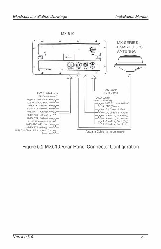
Electrical Installation Drawings Installation Manual
Version 3.0 211
�� ��
!�� �$%&'��(��� �)**��
��� �$%&'�+��,* �)**'-.)/�
��� ��.� �*01. �2'&&)3�
��� ��/''*�
�/4 �)*.$-. � ��&1'�
�/4 �)*.$-. � ��1/0&'�
0''5 !)6 �� ��/'4�
0''5 !)6 �� � �#7,.'�
0''5 !)6 �1. ��/6�
0''5 !)6 �1. � ��/*�
�*.'**$ �$%&' ����,* �)**'-.)/8�
�'6$.,9' ��� ��&$-:�
��� .) �� ��� ��'5�
���� ��� � ��&1'�
���� ��� ��/)3*�
���� ��� � ��/$*6'�
���� ��� ��/''*�
���� ��� � �2'&&)3�
���� ��� �#7,.'�
���� ��� � ��1/0&'�
���� ��� ��/'4�
��� ;$8. �7$**'& �� �!,.' �/''*�
7,'&5
�#���$.$ �$%&'�����,* �)**'-.)/�
�� ���� ���� ��� �������
Figure 5.2 MX510 Rear-Panel Connector Configuration

Electrical Installation DrawingsInstallation Manual
212 Version 3.0
�) <$/.���� �*.'**$
��������������� ��������� ����
�) ���� �=1,0<'*.
����� ���
�
�*.'**$ �$%&' �884�
���������
Figure 5.3 MX510 with Optional Junction Box

Electrical Installation Drawings Installation Manual
Version 3.0 213
�����>"+?�����
�&$-: ��'6$.,9' ����
�'5 ����� ��� �*01.��&1' ������ ���� �/)3* ������ ��� �/$*6' ������ ���� �/''* ������ � �� 2'&&)3 ������ ���� #7,.' ������ ���
�1/0&' ������ ���� �/'4 ������ ���
!,.' �/''* �;$8. �7*& �� ����
� 7,'&5�
����,* �;'<$&'� �)**'-.)/ �88'<%&4
� <'.'/8
Figure 5.4 Power/Data Cable Diagram
�����>"+
2'&&)3 ���� ��.� �*01.�
�&1' ��/4 �)*.$-. ���1/0&' ��/4 �)*.$-. ���/'4 � 0''5 !)6 �� �#7,.' � 0''5 !)6 �� ���/$*6' � 0''5 !)6 ��� ��/)3* ���� � ���
+��,* �;'<$&'� �)**'-.)/ �88'<%&4
� <'.'/8
Figure 5.5 Auxiliary Cable Diagram
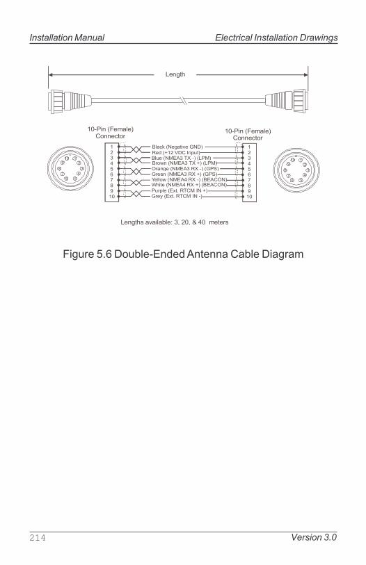
Electrical Installation DrawingsInstallation Manual
214 Version 3.0
�����>"+?�
�&$-: ��'6$.,9' ����
�'5 ��� ��� �*01.��&1' ������ �� �!����� �/)3* ������ � �!����� �/$*6' ������ �� ��� ��� �/''* ������ � ��� ��� 2'&&)3 ������ �� ���������� #7,.' ������ � ����������
�1/0&' ���.� ���� �� ��/'4 ���.� ���� �� ��
�����>"+?�
���,* �;'<$&'� �)**'-.)/
���,* �;'<$&'� �)**'-.)/
�
�
�
�
�>
"
+
?�
�
�
�
�
�>
"
+
?�
!'*6.7
!'*6.78 $9$,&$%&'@ �A �A � � <'.'/8
Figure 5.6 Double-Ended Antenna Cable Diagram

Electrical Installation Drawings Installation Manual
Version 3.0 215
B2'&&)3 ��'$-)* .$.18 �1.��
�/''* ��� �1.�
+
?�
�
�
�
�>
"
�
�&$-:�����
B#7,.' ��'$-)* .$.18 �1.�
BB�1/0&' ����� �� )/ ��� �
BB�/$4 ����� ,* � )/ ��� ��
�/$*6'��� �1.��
�'5 ��� ��� ,*�
�&1' ���� �* ��
�/)3* ���� �* �
�,*C #,/' ,6*$&
+B
?BB�BB
#�1/0&' ��� �� �/$4 ��� ���
��.� ���� �* ��1/0&'�
��.� ���� �* � ��/$4�
7,.'
"B 2'&&)3
> �/''* �
�'$-)* .$.18 �1. �'$-)* .$.18 �1. �
� �1. � �/$*6' �� �1. �� �/)3* ��� ��� �&1' �� ���� �
�&$-:
'5 �� ���� ����
B�). -)**'-.'5 ,* ����� ��� )*&4� �*.'**$ <)5'&
BB�,*8 ? �� $9$,&$%&' )*&4 )* ������� $*.'**$ <)5'&BB�,*8 ? � � D)/ ��.� ���� ,*01. )* ����� ��� $*.'**$
�������� ���� � ��� )/ ���� ���
�'$-)* .$.18 �* � �2'&&)3������ �� ��/''*������ �� � ��/$*6'������ �� ��/)3*������ �� � ��&1'��� ��� �� ��'5��'6$.,9' ��� ��&$-:�
Figure 5.7 Smart D/GPS Antenna Wiring Diagram

Electrical Installation DrawingsInstallation Manual
216 Version 3.0
�� ���
� ,*
� ,* � )1.
� )1.
���
�!E
���
���
���
�!�
#F�
2�!���
��2
� ,* � )1.
� ,* � )1.
� ,* � )1.
� ,* � )1.
��� ���
�� �
�;� ���
� )1. � )1.
� )1. � )1.
� )1. � )1.
� )1. � )1.
� )1. � )1.
� )1. � )1.
�00'/ !)3'/
0&,..'/ �1.01.8
��.�
�&$/<8
05
!)6
;�
��� ���
� ��
� )1. � ,*
� )1. � ,*
�!� ���
#F� �!E
2�! ���
��! ���
��2 ���
��� �;�
� )1. � ,*
� )1. � ,*
� )1. � ,*
� )1. � ,*
��� ��
!)3'/ �00'/
�)/. �
��)/. �
��� <$/. �*.'**$
�#�
(���� D)/ ��������
����������������
������ ���
�).'8@�� �#�A ��� $*5 ��� -$%&'8 $/' 0/'�,*8.$&&'5 ,* G1*-.,)* %)�� �� ;� ;18' � � �<0
���
�!E
���
2�!
2�!��!E
��2
������ ��� �)<0$88
�!E
���
�����"�� ��� <�
�����+�� �� ��
����������� ���
���� �$%&' ���� ��+ �� "���
��� �$%&' ���� � � ���
���� �
���� �
���� �
���� �
���� �
���� �
�#������ �$%&' ���� � � ���
Figure 5.8 MX510 to MX575A GPS Compass Wiring
Diagram

Electrical Installation Drawings Installation Manual
Version 3.0 217
���������
��� �� �� �
�����
����
�����
�����
�����
�����
�����
�����
�����
�����
�����
�����
�����
�����
����
����
����
����
���������
���� ��� ��� ��
������
�����
��� �� �� �
����
����
����
�����
����
����
�����
����
�����
����
��
�����
�����
� ����!��
��"�
�#�$%����
�"$
�������
�#�"������
����%������
#�����&#
#�����&#
���'�%#��$�&��(�
�������
$�&������#
#�(���
#���#���
������#�&�$
)����&#���#�
��� �� �� ��
�����
�����
����������
Figure 5.9 MX500/MX510-JB Junction Box Wiring Diagram

Electrical Installation DrawingsInstallation Manual
218 Version 3.0
����
��.� ��� 05� �1&8'8��.� �&$/<8
!���(����)**�
!���(����)**�
�)3'/ � ���� �$.$�*.'/D$-'
�/)88��9'/�$%&' �884�
�� ��� �����!���� ����
�)3'/ � ���� �$.$�*.'/D$-'
����
��.� ��� 05� �1&8'8��.� �&$/<8
Figure 5.10 MX510 Dual-Control Configuration
���� C����� C�
�).'@ ���� &,-'*8' /'=1,/'5 )* %).7 ����� 1*,.8
����
��.� ��� 05� �1&8'8��.� �&$/<8
!���(����)**�
!���(����)**�
�)3'/ � ���� �$.$�*.'/D$-'
�/)88��9'/�$%&' �884�
�)3'/ � ���� �$.$�*.'/D$-'
����
��.� ��� 05� �1&8'8��.� �&$/<8
Figure 5.11 MX510 Backup Receiver Integrity
Monitoring Configuration

Electrical Installation Drawings Installation Manual
Version 3.0 219
�����
�)3'/ � ���� �$.$�*.'/D$-'
��.� ��� 05� �1&8'8��.� �&$/<8!��
�(����)**�
!���(����)**�
�)3'/ � ���� �$.$�*.'/D$-'
�� ��� ����
!��� ���� C�
F1%� 3,.-7��)1.'/
!���(����)**�
�)3'/ � ���� �$.$�*.'/D$-'
!��� ���� C�
!���(����)**�
�)3'/ � ���� �$.$�*.'/D$-'
!���(����)**�
�)3'/ � ���� �$.$�*.'/D$-'
�������� ���� C�
��������
���� C�
�� ����
����
���� ����
����
Figure 5.12 Multiple Control Configuration

Electrical Installation DrawingsInstallation Manual
220 Version 3.0
Notes:

MX512 Electrical Installation Drawings Installation Manual
Version 3.0 221
SECTION 6
MX 512
ELECTRICAL INSTALLATION DRAWINGS

Electrical Installation DrawingsMX512 Installation Manual
222 Version 3.0
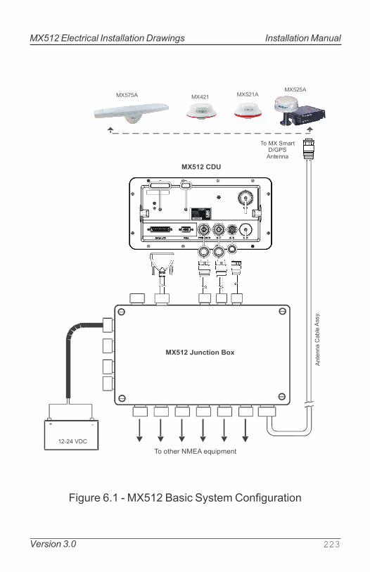
MX512 Electrical Installation Drawings Installation Manual
Version 3.0 223
����������� ��������
��������
�������� ��������
��������������������
���������
� �
�������� !��""#$
����� ��%�����%�%�
��%&%�
Figure 6.1 - MX512 Basic System Configuration

Electrical Installation DrawingsMX512 Installation Manual
224 Version 3.0
����������� ��������
��������
�������� ��������
��������������������
���������
� ��������� !��""#$
�������������������
�������������
Figure 6.2 - MX512 Junction Box Assembly

MX512 Electrical Installation Drawings Installation Manual
Version 3.0 225
��'�%(&)*�+����
,!�-.�/��0��1�� ��2
3�4�/��+�'������5���2,!���/������ �2���,�6��/������ �2���7��0��/������ �23�� ����/����� �2�3���8�!!�6�/������ �2���9����/������ �2���
���!��/������ �23�� �#�/������ �23��
:��� ����/;�"����!�5�� 2 ��
�/����!42
�������/;���!�2������-���""�� !#
'����"
Figure 6.3 - 12-Pin Power/Data Cable Assembly Diagram
��'�%(&)
8�!!�6�/�7,��<$�5���2
,!���/�#�����-��2���!��/�#�����-��2 �#�/����4�:�0�5���29����/����4�:�0�5���27��0��/����4�:�0�7=���2,�6��/�7��=���2
)�����/;���!�2������-���""�� !#
'����"
Figure 6.4 - Auxiliary Cable Assembly Diagram

Electrical Installation DrawingsMX512 Installation Manual
226 Version 3.0
��'�%(&)*�+
,!�-.�/��0��1�� ��23�4�/��������5���2,!���/����'� �2�/:��2���,�6��/����'� �2�/:��2���7��0��/����'� �2�/ ��23�� ����/����'� �2�/ ��23��8�!!�6�/������ �2�/,���7�23��9����/������ �2�/,���7�23��
���!��/�<$�3����5���2 �#�/�<$�3����5���2
��'�%(&)*�+
�+�����/;���!�2������-��
�+�����/;���!�2������-��
�
�
'
�
%(
&
)
*�+
�
�
'
�
%(
&
)
*�+
:��0�
:��0�"��1��!� !�>�'?��+?�@��+�����"��
Figure 6.5 - Double-Ended Antenna Cable Assembly Diagram

MX512 Electrical Installation Drawings Installation Manual
Version 3.0 227
������������������
A8�!!�6�/,��-������"�7��2
����/ ���7��2
)
*�+
�
'
�
%(
&
�
�����������������������
�,!�-./ ��2
A9����/,��-������"�7��2
AA���!��/3����5������������2
�����������AA �#�/3�����������������2
7��0�/ ���7��2
3�4�/����������2
,!���/����5���2
,�6��/����5���2
�
���B 9�� ��0��!��������� �� �������
)A
*AA�+AA
������������9���!�������/�2� �#������/�2�
�<$�3����5����/���!�2�
�<$�3����5����/ �#2
������
&A������������8�!!�6��
(������������ ������ �����
,��-������"�7���,��-������"�7���
���7���%������������7��0�� ����� ���7����������������,�6���� ���������5��'������������,!�������� ����� ���5���������������3
,!�-.�4������� ������������
������ ��� ��$
���A���-����-�4����������/ �����!#2����������4�!
AA���"�*�@�+��1��!� !����!#�����������+����������4�!AA���"�*�@��+�C���<$�3�������������<%���� ����������
�����,��+�/� ��2 ��%++����<%�+���=
,��-������"�5����/8�!!�62����'�3����/ ���2����'�3�����/7��0�2����'������/,�6�2����'�������/,!��2��������5��/3�42��0��1�� ���/,!�-.2
Figure 6.6 - MX421B-10 or MX521 DGPS Antenna Wiring
Diagram

Electrical Installation DrawingsMX512 Installation Manual
228 Version 3.0
3���/�������2
,:D�/�� 2 ,:D�/�� 2
3��/����'�3��2
73 �/����'�3��2
,3��/����'����2
,:=�/����'�����2
3��9E��/���2
3��/����2
,:=�9E��/3��2
9E��,:D�/3��2
��%�<���=��%&%��� ����7�����
�+��5����,:�����8$����'%+)��+��&+�%+/'�����3�2
��%&%��������,:�����8$����'%+)��+��&+&�+/�%�����3�2$
F=���57���,7��/�����%++��++��++�2���>������!!���"��C����G��-���� �<��"�"��6�������"�4��0��
Figure 6.7 - MX51x to MX575 Antenna Wiring Interface

MX512 Electrical Installation Drawings Installation Manual
Version 3.0 229
��%��
�<$��7,��4$���!"�"�<$��!��"
:��3F��%����$
:��3F��%����$
��6��@���������5��C�-�
��""�71��� !���""#$
�����3�=�5��:5����=�5�
��6��@���������5��C�-�
��%��
�<$��7,��4$���!"�"�<$��!��"
F�,�< F�,�<
7���������"
7���������"
Figure 6.8 - MX512 Dual Control Configuration
=�5��B�=�5��B�
���>��,35��!�-��"�������4���� �����%������"�
��%��
�<$��7,��4$���!"�"�<$��!��"
:��3F��%����$
:��3F��%����$
��6��@���������5��C�-�
��""�71��� !���""#$
��6��@���������5��C�-�
��%��
�<$��7,��4$���!"�"�<$��!��"
7���������"
F�,�< F�,�<
7���������"
Figure 6.9 - MX512 Backup Receiver Integrity
Monitoring Configuration

Electrical Installation DrawingsMX512 Installation Manual
230 Version 3.0
�<%��
��6��@���������5��C�-�
�<$��7,��4$���!"�"�<$��!��":��
3F��%����$
:��3F��%����$
��6��@���������5��C�-�
�����3�=�5�
�:����=�5��B�
E� ��6�-��3���
:��3F��%����$
��6��@���������5��C�-�
�:����=�5��B�
:��3F��%����$
��6��@���������5��C�-�
:��3F��%����$
��6��@���������5��C�-�
3������3�=�5��B�
3������3
�=�5��B�
�5�3��������������=��
�<%��
�<%�� �<%��
�<%��
Figure 6.10 - Multiple Unit Control Configuration
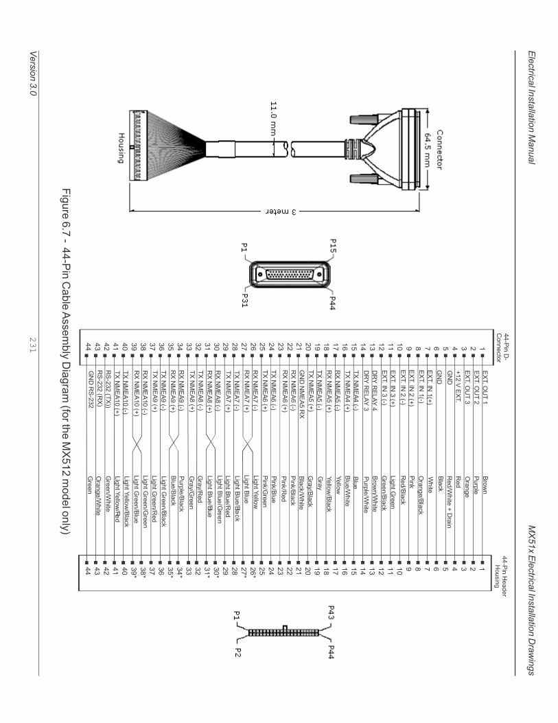
MX
51x E
lectric
al In
sta
llatio
n D
raw
ings
Ele
ctric
al In
sta
llatio
n M
anual
Vers
ion 3
.0231
Fig
ure
6.7
- 44-P
in C
able
Assem
bly
Dia
gra
m (fo
r the M
X512 m
odel o
nly
)
���������
������
���������
��
��
��
��
��
��
��
��
��
��
��
��
��
��
��
��
��
��
��
��
��
��
��
��
��
��
��
��
��
��
��
��
��
��
��
�����������
��
��
��
��
��
��
��
��
��
��
��
��
��
��
��
���
���
��
��
���
���
��
��
���
���
��
��
���
���
��
��
��
��
��
����������
����������
����������
!�
!�
�����"!��#�$
�����"!��#�$
�����"!���#�$
�����"!���#�$
�����"!���#�$
�����"!���#�$
�%&�%�'(&��
�%&�%�'(&��
���!)�(��#�$
���!)�(��#�$
%��!)�(��#�$
%��!)�(��#�$
����������
���!)�(��#�$
���!)�(��#�$
!��!)�(��%�
%��!)�(��#�$
%��!)�(��#�$
���!)�(��#�$
���!)�(��#�$
%��!)�(��#�$
%��!)�(��#�$
���!)�(��#�$
���!)�(��#�$
%��!)�(��#�$
%��!)�(��#�$
���!)�(��#�$
���!)�(��#�$
%��!)�(��#�$
%��!)�(��#�$
���!)�(��#�$
���!)�(��#�$
%��!)�(���#�$
%��!)�(���#�$
���!)�(���#�$
���!)�(���#�$
%*�����#��$$
%*�����#%�$
!��%*����
+ ,�
�- ./
� 0�1
%2
%2345������ 0��
+/0�6
45��
� 0�13+/0�6
���6
%23+/0�6
'�15�� �
�3+/0�6
+ ,�345��
�- ./345��
+/-
+/-345��
&//,3+/0�6
073+/0�6
07
&//,
+/0�6345��
���63+/0�6
���63%2
���63+/-
���63 �
'�15��+/-
'�15��&//,
'�15��+/-3+/0�6
'�15��+/-3%2
'�15��+/-3+/-
'�15��+/-3 �
073%2
073 �
+/-3+/0�6
�- ./3+/0�6
'�15�� �3+/0�6
'�15�� �3%2
'�15�� �3+/-
'�15�� �3 �
'�15��&//,3+/0�6
'�15��&//,3%2
�345��
� 0�1345��
�

Ele
ctric
al In
sta
llatio
n D
raw
ings
232
Vers
ion 3
.0
MX
51x In
sta
llatio
n M
anual
%��
+'8
%!
�%
+%!
+'�
49�
&�'
��%
%&
%��
+'8
&�'
�%
%&
+%!
��������������������
� �*�*:0 ��(����0;
+'�
49�
%!
�%�'
)�+
�4%�<("'
!���
�4%�<("'
�
�4%�<("')�+
��%��� )���� *����'�
�����('(%)
�"�� �"�� �"�� ��%��� ��%��� ��%��� ��%��� ��%��� ��%��� �%���� �%���� ���
!��!)�(�
%�
!�
(�"�
(��-�
+�"�
+��-�
!�
(��-�
!��!)�(�
+��-�
(�"�
(��-�
+�"�
+��-�
(�"�
(��-�
+�"�
+��-�
(�"�
(��-�
+�"�
+��-�
(�"�
(��-�
+�"�
+��-�
(�"�
(��-�
+�"�
+��-�
(�"�
(��-�
+�"�
+��-�
!�
%*����� !�
%*�������
%*�����%�
(�"�
(��-�
+�"�
+��-�
(�"�
(��-�
+�"�
+��-�
(�"�
(��-�
+�"�
+��-�
(�"�
(��-�
+�"�
+��-�
%��
+'8
%!
�%
+%!
+'�
49�
&�'
��%�'�
%&
�������
!��#�$
�%&�%�'(&
��%&�%�'(&
�
�%&�%�'(&
��%&�%�'(&
�
����%
'�4�%
���"*
�"'��
��%�
� �*
�9�="!��9�="!�
�9�= !��9�= !�
�9�="!��9�="!�
�9�="!��9�="!�
�9�= !��9�= !�
�9�="!��9�="!�
�9�=�����9�=����
�9�="!��9�="!�
�9�=�����9�=����
�9�= !��9�= !�
�9�="!�
�9�=����
�9�="!�
�9�=����
�9�="!�
�9�=����
�9�="!�
�9�=����
�9�= !�*�%= !�
*�%="!�
*�%=����
*�%="!�
*�%=����
�9�=�(!9
�9�=�"!
�9�=�(!'
�9�= !�
�9��=��9��=�
>�
>�
>�
>�
>�
>�
>�+�"�
+��-�
(�"�
(��-�
��%���
��������
����%'�4�%
����� �
� ��� ��-�.-�
�����)�+
*4"��9
� ��
��2+�* �0/
�����
��� �
!�;?
����0@/;��A�����B���0 �. ���;�0//2����
�����5�C-������@D�
45 ?�
������(����0@/�#������������$
������(!���0@/�#��������������$
�������4%3�(�(��0@/�#������������$
��������������0@/�#������������$
���>��0�2�>��/0@/;�, ��/0 12�
����E �0;7� 02��1�
Fig
ure
6.1
2 - M
X512 a
nd S
mart A
nte
nna J
unctio
n B
ox C
onnectio
n D
iagra
m

MX
51x E
lectric
al In
sta
llatio
n D
raw
ings
Ele
ctric
al In
sta
llatio
n M
anual
Vers
ion 3
.0233
)�+
�4%�<("'
!���
�4%�<("'
�
�4%�<("')�+
��%��� )���� *����'�
�����('(%)
�"�� �"�� �"�� ��%��� ��%��� ��%��� ��%��� ��%��� ��%��� �%���� �%���� ���
!��!)�(�
%�
!�
(�"�
(��-�
+�"�
+��-�
!�
(��-�
!��!)�(�
+��-�
(�"�
(��-�
+�"�
+��-�
(�"�
(��-�
+�"�
+��-�
(�"�
(��-�
+�"�
+��-�
(�"�
(��-�
+�"�
+��-�
(�"�
(��-�
+�"�
+��-�
(�"�
(��-�
+�"�
+��-�
!�
%*����� !�
%*�������
%*�����%�
(�"�
(��-�
+�"�
+��-�
(�"�
(��-�
+�"�
+��-�
(�"�
(��-�
+�"�
+��-�
(�"�
(��-�
+�"�
+��-�
%��
+'8
%!
�%
+%!
+'�
49�
&�'
��%�'�
%&
�������
!��#�$
�%&�%�'(&
��%&�%�'(&
�
�%&�%�'(&
��%&�%�'(&
�
����%
'�4�%
���"*
�"'��
��%�
� �*
�9�="!��9�="!�
�9�= !��9�= !�
�9�="!��9�="!�
�9�="!��9�="!�
�9�= !��9�= !�
�9�="!��9�="!�
�9�=�����9�=����
�9�="!��9�="!�
�9�=�����9�=����
�9�= !��9�= !�
�9�="!�
�9�=����
�9�="!�
�9�=����
�9�="!�
�9�=����
�9�="!�
�9�=����
�9�= !�*�%= !�
*�%="!�
*�%=����
*�%="!�
*�%=����
�9�=�(!9
�9�=�"!
�9�=�(!'
�9�= !�
�9��=��9��=�
>�
>�
>�
>�
>�
>�
>�+�"�
+��-�
(�"�
(��-�
��%���
��������
����%'�4�%
����� �
� ��� ��-�.-�
�����)
�+
*4"��9
� ��
��2+�* �0/
�����
��� �
!�;?
����0@/;��A�����B���0 �. ���;�0//2����
�����5�C-������@D�
45 ?�
������(����0@/�#������������$
������(!���0@/�#��������������$
�������4%3�(�(��0@/�#������������$
��������������0@/�#������������$
���>��0�2�>��/0@/;�, ��/0 12�
����E �0;7� 02��1�
%��
+'8
%&
&�'
&�'3+'8
+%! )����(�� �*
�:.0;;
Fig
ure
6.1
3 - M
X512 a
nd M
X575A
Junctio
n B
ox C
onnectio
n D
iagra
m

Ele
ctric
al In
sta
llatio
n D
raw
ings
234
Vers
ion 3
.0
MX
51x In
sta
llatio
n M
anual
Note
s