mx component version 4 programming manual
TRANSCRIPT

MX Component Version 4 Programming Manual
-SW4DNC-ACT-E

1
SAFETY PRECAUTIONS(Read these precautions before using this product.)
Before using this product, please read this manual and the relevant manuals carefully and pay full attention
to safety to handle the product correctly.
In this manual, the safety precautions are classified into two levels: " WARNING" and " CAUTION".
Under some circumstances, failure to observe the precautions given under " CAUTION" may lead to
serious consequences.
Make sure that the end users read this manual and then keep the manual in a safe place for future
reference.
[Design Instructions]
WARNING● When data change, program change, or status control is performed from a personal computer to a
running programmable controller, create an interlock circuit outside the programmable controller to
ensure that the whole system always operates safely.
Furthermore, for the online operations performed from a personal computer to a programmable
controller CPU, the corrective actions against a communication error due to such as a cable
connection fault should be predetermined as a system.
CAUTION● The online operations performed from a personal computer to a running programmable controller
CPU (forced output and operating status changes) must be executed after the manual has been
carefully read and the safety has been ensured.
The operation failure may cause the injury or machine damage.
WARNING
CAUTION
Indicates that incorrect handling may cause hazardous conditions,
resulting in death or severe injury.
Indicates that incorrect handling may cause hazardous conditions,
resulting in minor or moderate injury or property damage.
2
CONDITIONS OF USE FOR THE PRODUCT
(1) Mitsubishi programmable controller ("the PRODUCT") shall be used in conditions;
i) where any problem, fault or failure occurring in the PRODUCT, if any, shall not lead to any major
or serious accident; and
ii) where the backup and fail-safe function are systematically or automatically provided outside of
the PRODUCT for the case of any problem, fault or failure occurring in the PRODUCT.
(2) The PRODUCT has been designed and manufactured for the purpose of being used in general
industries.
MITSUBISHI SHALL HAVE NO RESPONSIBILITY OR LIABILITY (INCLUDING, BUT NOT
LIMITED TO ANY AND ALL RESPONSIBILITY OR LIABILITY BASED ON CONTRACT,
WARRANTY, TORT, PRODUCT LIABILITY) FOR ANY INJURY OR DEATH TO PERSONS OR
LOSS OR DAMAGE TO PROPERTY CAUSED BY the PRODUCT THAT ARE OPERATED OR
USED IN APPLICATION NOT INTENDED OR EXCLUDED BY INSTRUCTIONS, PRECAUTIONS,
OR WARNING CONTAINED IN MITSUBISHI'S USER, INSTRUCTION AND/OR SAFETY
MANUALS, TECHNICAL BULLETINS AND GUIDELINES FOR the PRODUCT.
("Prohibited Application")
Prohibited Applications include, but not limited to, the use of the PRODUCT in;
• Nuclear Power Plants and any other power plants operated by Power companies, and/or any
other cases in which the public could be affected if any problem or fault occurs in the PRODUCT.
• Railway companies or Public service purposes, and/or any other cases in which establishment of
a special quality assurance system is required by the Purchaser or End User.
• Aircraft or Aerospace, Medical applications, Train equipment, transport equipment such as
Elevator and Escalator, Incineration and Fuel devices, Vehicles, Manned transportation,
Equipment for Recreation and Amusement, and Safety devices, handling of Nuclear or
Hazardous Materials or Chemicals, Mining and Drilling, and/or other applications where there is a
significant risk of injury to the public or property.
Notwithstanding the above, restrictions Mitsubishi may in its sole discretion, authorize use of the
PRODUCT in one or more of the Prohibited Applications, provided that the usage of the PRODUCT
is limited only for the specific applications agreed to by Mitsubishi and provided further that no
special quality assurance or fail-safe, redundant or other safety features which exceed the general
specifications of the PRODUCTs are required. For details, please contact the Mitsubishi
representative in your region.

3
OPERATING CONSIDERATIONS
This section explains the considerations in the following order.
1) Considerations of operating system and personal computer to be used2) Considerations of installation and uninstallation3) Programmable controller CPU-related considerations4) Considerations for using other MELSOFT products5) Considerations for using Ethernet modules6) Considerations for using CC-Link modules7) Considerations for using serial communication modules8) Considerations of modem communication9) Considerations of programming
10) Considerations for using Microsoft® Excel®
11) Considerations for using Microsoft® Access®
12) Considerations for using VBScript13) Considerations for using of Robot controller
(1) Restrictions applied when a user without Administrator’s authority operates MX ComponentNote that the following restrictions are applied when a user without Administrator’s authority operates MX
Component.
(a) Communication Setup Utility
• The logical station number cannot be created, changed, or deleted.
• Communication settings cannot be imported.
• This utility cannot be started up if the communication settings are set using MX Component earlier than
Version 3.00A.*1
(b) PLC Monitor Utility
• This utility cannot be started up if the communication settings are set using MX Component earlier than
Version 3.00A.*1
• Device registration cannot be performed on the <<Entry Device>> tab.
(c) Communication board
• Various settings cannot be set on the CC-Link IE Controller Network, CC-Link IE Field Network,
MELSECNET/H, and CC-Link board utilities.
*1 : If the following error message is displayed, start up and close the utility as a user with Administrator’s authority. This operation enables a user without Administrator’s authority to start up the utility.
(2) Resume and other functions of personal computer
A communication error may occur when communicating with the programmable controller CPU after setting the
resume function, suspend setting, power-saving function, and/or standby mode of the personal computer.
Therefore, do not set the above functions when communicating with the programmable controller CPU.
Considerations of operating system and personal computer to be used

4
(1) Installation
When performing overwrite installation, install the software in the same folder where it is installed previously.
(2) Start menu
When MX Component is uninstalled, the item may remain in the start menu.
In this case, restart the personal computer.
(3) When downloading the installer
When downloading the installer, save the installer to a directory which does not include any space and execute it.
(1) Considerations for performing USB communication
ON/OFF of a programmable controller CPU during communications with the programmable controller CPU may
cause a communication error which cannot be recovered.
If it is not recovered, completely disconnect the USB cable and then reconnect it after 5 or more seconds.
(If this error occurs at the initial communication after the above operation, the function will be performed properly
in and after the second communications.)
(2) Clock data of programmable controller CPU
(a) For QCPU (Q mode), LCPU, and FXCPU, the clock data setting can be set if the programmable controller CPU is in the RUN status.
(b) For QCPU (Q mode) and LCPU, the setting can be set regardless of the ON/OFF status of the time setting device "SM1028".
(c) The clock data can be set on FXCPUs with the built-in clock or FXU/FX2C/FX2NC with the RTC cassette.
(d) Note that an error for transfer time occurs in the time setting.
(3) Restrictions on using FXCPU
(a) When FXCPU is used, the TN devices (timer present values) or CN devices (counter present values) cannot be accessed if the device numbers specified are split across 199 or earlier and 200 or later.
(b) Since FXCPU does not feature the PAUSE switch as the programmable controller CPU, an error is returned if remote pause is specified in SetCpuStatus.
(c) Note that specifying the first I/O number of a non-existing module and executing the WriteBuffer() method will not return an error.
(d) For the index registers (Z, V) of FXCPU, data cannot be written to 2 or more consecutive points using WriteDeviceBlock(). (Data may be written to only one point.)
(4) Serial communication function of Q00UJ/Q00/Q00U/Q01/Q01U/Q02UCPU*1
*1 : In this section, "serial communication function compatible CPU" indicates Q00UJ/Q00/Q00U/Q01/Q01U/Q02UCPU.
When the following conditions are all satisfied, communication between the personal computer and the serial
communication function compatible CPU is set at 9600bps speed.
• 1)The serial communication function of the connected CPU is valid.
• 2)The transmission speed settings differ between the personal computer and the serial communication
function compatible CPU side.
To increase the communication speed, match the transmission speed of personal computer with that of serial
communication function compatible CPU.
Considerations of installation and uninstallation
Programmable controller CPU-related considerations

5
(5) Considerations for using built-in Ethernet CPU
When resetting the programmable controller CPU during TCP/IP connection establishment (during opening)
using MX Component, a communication error or receive error occurs at subsequent communication.
In this case, perform the close processing in the application that uses MX Component, and perform the open
processing again.
(6) Considerations for using QSCPU
In order to protect the safety programmable controller system, functions to write data to buffer memory, to write/
set devices, and to write clock data cannot be executed.
(7) Considerations for using FX5CPU
(a) Since FX5CPU does not feature the PAUSE switch as the programmable controller CPU, an error is returned if remote pause is specified in SetCpuStatus.
(b) FX5CPU does not support the ReadBuffer() and WriteBuffer() methods. For writing/reading buffer memory, specify the device (U*\G*).
(1) Considerations for performing GX Simulator communication
Before executing PLC Monitor Utility, Communication Setup Utility, or a user program, check that GX Simulator
and GX Developer are operating.
If GX Simulator or GX Developer is terminated while the user program is running, the user program will not be
terminated normally.
(2) Considerations for performing MT Simulator2 communication
• After installing MT Component, install MT Developer2.
• The maximum number of connections*1 to MT Simulator2 is 4.
*1 : Including in MT Developer2.Example) When two MT Developer2s and one MT Simulator2 are activated: three connections can be established from MT Component.
(1) Resetting programmable controller CPU during TCP/IP connection establishment
When resetting the programmable controller CPU during TCP/IP connection establishment (during opening)
using MX Component, a communication error or receive error occurs at subsequent communication.
In this case, perform the close processing in the application that uses MX Component, and perform the open
processing again.
(2) Target existence check starting interval of Ethernet module
If the close processing (Close) is executed from the personal computer, the Ethernet module may not perform the
close processing (Close). One of its causes is the cable disconnection.
If the open processing (Open) is executed from the personal computer with the Ethernet module not executing the
close processing (Close), the open processing (Open) from the personal computer is not terminated normally until
the Ethernet module performs a target existence check and executes the close processing (Close).
When terminating the open processing (Open) early from the personal computer, shorten the target existence
check starting interval setting of the Ethernet module.
(The default setting of target existence check starting interval of the Ethernet module is 10 minutes.)
Considerations for using other MELSOFT products
Considerations for using Ethernet modules

6
(3) Replacement of Ethernet module
If the Ethernet modules are changed during Ethernet communication due to debugging, failure or the like, the
other node (personal computer) must be restarted.
(Because the Ethernet addresses (MAC addresses) differ between devices.)
(4) Simultaneous access when using Q series-compatible Ethernet module
The following conditions should be satisfied when communication is performed simultaneously from multiple
personal computers to the same module using the TCP/IP protocol.
• Q series-compatible E71 module (except QJ71E71-100) whose first five digits of the serial number is
"02122" or higher and whose function version is B or later.
• Using GX Developer Version 6.05F or later, set "MELSOFT connection" in the Ethernet parameter
[open system].
(5) Unlocking password when using QJ71E71
The range where the password can be unlocked by remote operation is up to the connection target station.
If the password is also set on the lower layer, communication cannot be performed with the programmable
controller CPU on the lower layer.
AAAA
Startingsource
1)QJ71E71
QCPU(Qmode)
2)QJ71E71
5)QJ71E71
4)QJ71E71
QCPU(Qmode)
3)QJ71E71
1)
2)
3)
4)
5)
Ethernet
Ethernet
Without setting
1) Unlocking QJ71E71 password enables access to Programmable controller CPUs in this range.
: Accessible: Inaccessible
Enter password tounlock.
QCPU(Qmode)
QCPU(Qmode)
No. Remote Password
With setting (AAAA)
Without setting
With setting (AAAA)
With setting (BBBB)

7
(6) Ethernet communication
(a) The communication line is disconnected if the CPU becomes faulty or the Ethernet module is reset during
Ethernet communication (when the protocol is TCP/IP).
In this case, perform the line close processing (Close) and then perform the reopen processing (Open).
(b) When two different communication systems (protocols) are used to access from one personal computer to one
Q series-compatible E71, two station numbers for TCP/IP and for UDP/IP must be set. However, it is not
required to set different station numbers for TCP/IP and for UDP/IP when using MX Component Version 3 or
later and Q series-compatible E71 with serial number 05051 or higher.
When MX Component uses TCP/IP and GX Developer uses UDP/IP
(1) Software version of CC-Link master/local module
For CC-Link master/local modules used in CC-Link communication, use modules of software version "N" or later.
Modules of software version "M" or earlier do not operate normally.
(1) Serial communication
(a) On any serial communication modules, remote "PAUSE" operation will result in an error for all connections.
(b) The FX extended port is required when performing the serial communication using FX0N, FX1S, FX1N(C), FX3S,
FX3G(C), or FX3U(C)CPU.
(2) Considerations for connecting personal computer and serial communication module
(a) When using QJ71C24-R2 of function version A
An MX Component application can use only either of CH1 and CH2.
When the MELSOFT product (GX Developer, GOT, or the like) is using one channel, the application cannot use
the other channel.
When QJ71C24-R2 of function version B is used, the application can use both channels.
Q series-compatible E71
(Station number: 1)(TCP/IP) station number for MX Component: 2
(UDP/IP) station number for GX Developer : 3
Personal computer
GX Developer(UDP/IP)
MX Component(TCP/IP)
Set different station numbers as the (TCP/IP) station number for MX Component
and (UDP/IP) station number for GX Developer. If they are set to the same station
number, an error will occur on the Ethernet module side.
Considerations for using CC-Link modules
Considerations for using serial communication modules

8
(1) Simultaneous modem communications
The simultaneous modem communications using MX Component and other applications (GX Developer or the
like) cannot be performed.
Do not perform a modem communication using other applications during a modem communication using MX
Component.
If modem communications are simultaneously performed using MX Component and other application, this will
result in a communication error, disconnection of telephone line or similar problem.
(2) Considerations for using telephone line
(a) Do not use the call-waiting phone line.
On the call-waiting phone line, data corruption, telephone line disconnection, or similar problem may occur due
to interrupt reading sounds.
(b) Do not connect the line to master/slave phones.
If the handset of the slave phone is lifted while the telephone line is connecting to the master/slave phones, the
telephone line may be disconnected.
(c) Use an analog 2 wire type telephone line.
When using a digital line, use a terminal adapter.
When the telephone line is 4 wire type, the line may not be connected depending on the wiring type of the
modular jack.
For the 4 wire type, conduct connection tests in advance to check for connections.
(3) Considerations for using cellular phone
(a) Modem for radio communication using a cellular phone
Although the modem name is different according to the manufacturer, the modem is generically referred to as
the cellular phone communication unit in this manual.
Select the model of the cellular phone communication unit according to the cellular phone used.
For details, contact the company of your cellular phone.
(b) Cellular phone without auto answer function
For the cellular phone without auto answer function, use a cellular phone communication unit that features the
ANS/ORG/TEL select switch.
If the cellular phone communication unit does not have the ANS/ORG/TEL select switch, the line cannot be
connected.
The line connection procedure is different according to the cellular phone company and cellular phone model.
For details, contact the manufacturer of your cellular phone.
Considerations of modem communication

9
(1) Sample programs, test programs, and sample sequence programs
(a) Sample programs and test programs
Sample programs are included for references when creating user programs.
Test programs are included for conducting communication tests.
Use the programs with your responsibility.
(b) Sample sequence programs
Sample sequence programs included in MX Component require modifications according to the system
configuration and parameter settings.
Modify the program to suit the system.
Use the programs with your responsibility.
(2) Forced termination of processes during communication
If communication is performed with the same type of control open for multiple processes, forcing one process to
be terminated by Task Manager or the like may stop the other processes at the communication function execution
area.
(3) Error at communication start
A communication error may occur within the preset time-out period at a communication start, for example, when
the communication diagnostic button is pressed, when a monitoring is started, or when any function is executed.
These errors are assumed to be detected before a time-out error.
(Example: When the communication cable is not connected, when the programmable controller power is OFF)
(4) CheckDeviceString
Do not use the CheckDeviceString method of ACT control.
(5) ActUMsg control and ActUWzd control
Installing MX Component registers the ActUMsg control and the ActUWzd control, however, do not use them.
(6) Considerations for using Ethernet modules
(a) Provide an interval longer than the sequence scan time of the Ethernet module mounted station for a period
from when the Open method is executed until the Close method is executed.
(b) Provide an interval of at least 500ms for a period from when the Close method is executed until the Open
method is executed again.
(7) Considerations for executing the Disconnect function
If a telephone line cannot be disconnected by executing the Disconnect function for some reason, power OFF the
modem being used to forcibly disconnect the telephone line.
(1) Considerations for using Excel VBA
If the page feed preview function is set in the application that uses Excel VBA, a memory leak or operating system
basic operation (file operation, printing, or the like) failure may occur.
Considerations of programming
Considerations for using Microsoft® Excel®

10
(2) Considerations for using Microsoft® Excel®
(a) Occasionally, controls may not be pasted to Excel.
This symptom occurs if the cache file (temporary file) of Excel remains.
In such a case, perform the operation in the following procedure.
Operating procedure
1. Close Excel.
2. Delete "*.exd" in the Excel 8.0 folder of the temp folders. *1, *2
3. Restart Excel.
*1 : The location of temp folder differs according to the operating system.*2 : When the corresponding folder and file are not displayed, set the settings in the folder option setting to display all files
and folders.
(b) Resizing of ACT control in Excel does not affect the operation of MX Component.
To restore the size, set the Height and Width properties of ACT control to "24".
(1) Considerations for using Microsoft® Access®
(a) When the ACT control is pasted to an Access form and the ACT control is double-clicked or the custom control
in the property is selected, the following error message is displayed. However, this does not affect the
operation of ACT control.
(An error message other than the following message may be displayed.)
(b) When the ACT control is pasted and the property is displayed, the displayed property name may be collapsed.
This symptom only occurs on the display of the property, and this does not affect the functions of the property.
(c) Resizing of ACT control in Access does not affect the operation of MX Component.
To restore the size, set the Height and Width properties of ACT control to "24".
(1) Security of the Internet/intranet when using VBScript
MX Component does not feature the Internet/intranet security function.
When the security function is required, set the setting on the user side.
Considerations for using Microsoft® Access®
Considerations for using VBScript

11
(1) When connecting robot controller with USB
For the considerations when connecting a robot controller with USB, refer to the following manual.
CR750/700/500 series RT ToolBox2 / RT ToolBox2 mini User's Manual
When connecting a robot controller with USB, an error does not occur for Open method of the control even when
the robot controller cannot be used.
If an error code 106 (connection is disconnected) occurred in the method after executing Open, execute Open
again after executing Close.
(2) Multiplex communication
Do not perform multiplex communication for one robot controller.
Considerations for using Robot controller

12
INTRODUCTION
Thank you for your patronage. We appreciate your purchase of the Mitsubishi integrated FA software, MELSOFT series.
This manual is designed for users to understand operations of MX Component.
Before using the product, thoroughly read this manual and related manuals to develop full familiarity with the functions and
performance of MX Component and supported modules to ensure correct use.
RELATED MANUALS
The manuals related to this product are shown below.
Refer to the following tables when ordering required manuals.
Remark
MX Component Version 4 Operating Manual is included on the CD-ROM of the software package in a PDF file format.Manuals in printed form are sold separately for single purchase. Order a manual by quoting the manual number (model code) listed in the table above.
Manual name
< Manual number, model code >Description
MX Component Version 4 Operating Manual
<SH-081084ENG, 13JU75>
Explains the programming procedures, detailed explanations and
error codes of the ACT controls.
Type Q80BD-J61BT11N/Q81BD-J61BT11 CC-Link System Master/
Local Interface Board User's Manual (For SW1DNC-CCBD2-B)
<SH-080527ENG, 13JR77>
Explains the system configuration, specifications, functions,
handling, wiring, and troubleshooting of the type Q80BD-J61BT11N/
Q81BD-J61BT11 CC-Link system master/local interface board.
MELSECNET/H Interface Board User's Manual
(For SW0DNC-MNETH-B)
<SH-080128, 13JR24>
Explains the system configuration, specifications, functions,
handling, wiring, and troubleshooting of the MELSEC/H board.
CC-Link IE Controller Network Interface Board User’s Manual
(For SW1DNC-MNETG-B)
<SH-080691ENG, 13JZ02>
Explains the system configuration, specifications, functions,
handling, wiring, and troubleshooting of the CC-Link IE
Controller Network board.
CC-Link IE Field Network Interface Board User’s Manual
(For SW1DNC-CCIEF-B)
<SH-080980ENG, 13JZ58>
Explains the system configuration, specifications, functions,
handling, wiring, and troubleshooting of the CC-Link IE
Field Network board.
MELSEC-Q C Controller Module User's Manual
<SH-081130ENG, 13JZ75>
Explains the system configuration, specifications, functions,
handling, wiring, troubleshooting, and programming and function of
Q24DHCCPU-V, Q24DHCCPU-LS, and Q12DCCPU-V (Extended
mode).
C Controller Module User's Manual
(Hardware Design, Function Explanation)
<SH-080766ENG, 13JZ17>
Explains the system configuration, specifications, functions,
handling, wiring, and troubleshooting of Q12DCCPU-V (Basic mode)
and Q06CCPU-V.
GX Simulator Version 7 Operating Manual
<SH-080468ENG, 13JU51>
Explains the setting and operating method for monitoring the device
memory and simulating the machine side operations using GX
Simulator.
GX Works2 Version 1 Operating Manual (Common)
<SH-080779ENG, 13JU63>
Explains the system configuration of GX Works2 and the functions
common to a Simple project and Structured project such as
parameter setting, operation method for the online function.

13
Memo

CONTENTS
14
CONTENTS
SAFETY PRECAUTIONS . . . . . . . . . . . . . . . . . . . . . . . . . . . . . . . . . . . . . . . . . . . . . . . . . . . . . . . . . . . . . 1CONDITIONS OF USE FOR THE PRODUCT . . . . . . . . . . . . . . . . . . . . . . . . . . . . . . . . . . . . . . . . . . . . . 2OPERATING CONSIDERATIONS. . . . . . . . . . . . . . . . . . . . . . . . . . . . . . . . . . . . . . . . . . . . . . . . . . . . . . . 3INTRODUCTION . . . . . . . . . . . . . . . . . . . . . . . . . . . . . . . . . . . . . . . . . . . . . . . . . . . . . . . . . . . . . . . . . . . 12RELATED MANUALS . . . . . . . . . . . . . . . . . . . . . . . . . . . . . . . . . . . . . . . . . . . . . . . . . . . . . . . . . . . . . . . 12HOW TO READ THIS MANUAL . . . . . . . . . . . . . . . . . . . . . . . . . . . . . . . . . . . . . . . . . . . . . . . . . . . . . . . 19TERMS . . . . . . . . . . . . . . . . . . . . . . . . . . . . . . . . . . . . . . . . . . . . . . . . . . . . . . . . . . . . . . . . . . . . . . . . . . 20
CHAPTER 1 OVERVIEW 23
1.1 Outline of Controls . . . . . . . . . . . . . . . . . . . . . . . . . . . . . . . . . . . . . . . . . . . . . . . . . . . . . . . . . . 23
1.2 Control and Function Lists . . . . . . . . . . . . . . . . . . . . . . . . . . . . . . . . . . . . . . . . . . . . . . . . . . . . 25
1.2.1 Control list . . . . . . . . . . . . . . . . . . . . . . . . . . . . . . . . . . . . . . . . . . . . . . . . . . . . . . . . . . . . . . . 25
1.2.2 Function list . . . . . . . . . . . . . . . . . . . . . . . . . . . . . . . . . . . . . . . . . . . . . . . . . . . . . . . . . . . . . . 26
CHAPTER 2 CONTROLS 27
2.1 Settings for Using Controls . . . . . . . . . . . . . . . . . . . . . . . . . . . . . . . . . . . . . . . . . . . . . . . . . . . . 27
2.1.1 When using VBA . . . . . . . . . . . . . . . . . . . . . . . . . . . . . . . . . . . . . . . . . . . . . . . . . . . . . . . . . . 27
2.1.2 When using VBScript . . . . . . . . . . . . . . . . . . . . . . . . . . . . . . . . . . . . . . . . . . . . . . . . . . . . . . . 31
2.1.3 When Using Visual Studio® .NET. . . . . . . . . . . . . . . . . . . . . . . . . . . . . . . . . . . . . . . . . . . . . . 32
2.2 Programming Procedure. . . . . . . . . . . . . . . . . . . . . . . . . . . . . . . . . . . . . . . . . . . . . . . . . . . . . . 43
2.2.1 When using VBA . . . . . . . . . . . . . . . . . . . . . . . . . . . . . . . . . . . . . . . . . . . . . . . . . . . . . . . . . . 43
2.2.2 When using VBScript . . . . . . . . . . . . . . . . . . . . . . . . . . . . . . . . . . . . . . . . . . . . . . . . . . . . . . . 44
2.2.3 When using Visual Basic® .NET . . . . . . . . . . . . . . . . . . . . . . . . . . . . . . . . . . . . . . . . . . . . . . 45
2.2.4 When using Visual C++® .NET . . . . . . . . . . . . . . . . . . . . . . . . . . . . . . . . . . . . . . . . . . . . . . . 46
2.2.5 When using Visual C#® .NET. . . . . . . . . . . . . . . . . . . . . . . . . . . . . . . . . . . . . . . . . . . . . . . . . 47
2.3 Device Types . . . . . . . . . . . . . . . . . . . . . . . . . . . . . . . . . . . . . . . . . . . . . . . . . . . . . . . . . . . . . . 48
2.4 Accessible Ranges . . . . . . . . . . . . . . . . . . . . . . . . . . . . . . . . . . . . . . . . . . . . . . . . . . . . . . . . . . 53
CHAPTER 3 PROPERTIES OF CONTROLS 54
3.1 Property List . . . . . . . . . . . . . . . . . . . . . . . . . . . . . . . . . . . . . . . . . . . . . . . . . . . . . . . . . . . . . . . 54
3.2 Details of Control Properties. . . . . . . . . . . . . . . . . . . . . . . . . . . . . . . . . . . . . . . . . . . . . . . . . . . 56
CHAPTER 4 PROPERTY SETTINGS OF COMMUNICATION PATHS 69
4.1 Descriptions of Property Setting . . . . . . . . . . . . . . . . . . . . . . . . . . . . . . . . . . . . . . . . . . . . . . . . 69
4.2 Serial Communication. . . . . . . . . . . . . . . . . . . . . . . . . . . . . . . . . . . . . . . . . . . . . . . . . . . . . . . . 70
4.2.1 Serial communication when the connected station is R series-compatible C24 . . . . . . . . . . 70
4.2.2 Serial communication when the connected station is Q series-compatible C24 . . . . . . . . . . 76
4.2.3 Serial communication when the connected station is L series-compatible C24. . . . . . . . . . . 82
4.2.4 Serial communication when the connected station is FX extended port . . . . . . . . . . . . . . . . 88
4.3 Ethernet Communication . . . . . . . . . . . . . . . . . . . . . . . . . . . . . . . . . . . . . . . . . . . . . . . . . . . . . 90
4.3.1 Ethernet communication when the connected station is R series-compatible E71 (TCP) . . . 90
4.3.2 Ethernet communication when the connected station is R series-compatible E71 (UDP) . . . 93
4.3.3 Ethernet communication when the connected station is Q series-compatible E71 (TCP) . . . 96
4.3.4 Ethernet communication when the connected station is Q series-compatible E71 (UDP). . . 99
4.3.5 Ethernet communication when the connected station is RCPU (TCP) . . . . . . . . . . . . . . . . 102

15
4.3.6 Ethernet communication when the connected station is RCPU (UDP) . . . . . . . . . . . . . . . . 105
4.3.7 Ethernet communication when the connected station is FX5CPU (TCP) . . . . . . . . . . . . . . 108
4.3.8 Ethernet communication when the connected station is FX5CPU (UDP) . . . . . . . . . . . . . . 110
4.3.9 Ethernet communication when the connected station is built-in Ethernet port QCPU
(TCP). . . . . . . . . . . . . . . . . . . . . . . . . . . . . . . . . . . . . . . . . . . . . . . . . . . . . . . . 112
4.3.10 Ethernet communication when the connected station is built-in Ethernet port QCPU
(UDP) . . . . . . . . . . . . . . . . . . . . . . . . . . . . . . . . . . . . . . . . . . . . . . . . . . . . . . . 116
4.3.11 Ethernet communication when the connected station is built-in Ethernet port LCPU
(TCP). . . . . . . . . . . . . . . . . . . . . . . . . . . . . . . . . . . . . . . . . . . . . . . . . . . . . . . . 120
4.3.12 Ethernet communication when the connected station is built-in Ethernet port LCPU
(UDP) . . . . . . . . . . . . . . . . . . . . . . . . . . . . . . . . . . . . . . . . . . . . . . . . . . . . . . . 123
4.3.13 Ethernet communication when the connected station is Ethernet adapter module
(TCP). . . . . . . . . . . . . . . . . . . . . . . . . . . . . . . . . . . . . . . . . . . . . . . . . . . . . . . . 126
4.3.14 Ethernet communication when the connected station is Ethernet adapter module
(UDP) . . . . . . . . . . . . . . . . . . . . . . . . . . . . . . . . . . . . . . . . . . . . . . . . . . . . . . . 130
4.3.15 Ethernet communication when the connected station is Ethernet adapter (TCP) . . . . . . . . 134
4.3.16 Ethernet communication when the connected station is Ethernet adapter (UDP) . . . . . . . . 136
4.3.17 Ethernet communication when the connected station is robot controller . . . . . . . . . . . . . . . 137
4.4 COM Communication . . . . . . . . . . . . . . . . . . . . . . . . . . . . . . . . . . . . . . . . . . . . . . . . . . . . . . .138
4.4.1 CPU COM communication when the connected station is FX5CPU . . . . . . . . . . . . . . . . . . 138
4.4.2 CPU COM communication when the connected station is QCPU (Q mode) . . . . . . . . . . . . 140
4.4.3 CPU COM communication when the connected station is LCPU . . . . . . . . . . . . . . . . . . . . 143
4.4.4 CPU COM communication when the connected station is Q motion CPU . . . . . . . . . . . . . 146
4.4.5 CPU COM communication when the connected station is FXCPU . . . . . . . . . . . . . . . . . . . 148
4.4.6 COM communication when the connected station is inverter . . . . . . . . . . . . . . . . . . . . . . . 150
4.4.7 COM communication when the connected station is robot controller . . . . . . . . . . . . . . . . . 151
4.5 USB Communication . . . . . . . . . . . . . . . . . . . . . . . . . . . . . . . . . . . . . . . . . . . . . . . . . . . . . . .152
4.5.1 USB communication when the connected station is RCPU . . . . . . . . . . . . . . . . . . . . . . . . . 152
4.5.2 USB communication when the connected station is R motion CPU . . . . . . . . . . . . . . . . . . 155
4.5.3 USB communication when the connected station is QCPU (Q mode). . . . . . . . . . . . . . . . . 158
4.5.4 USB communication when the connected station is LCPU . . . . . . . . . . . . . . . . . . . . . . . . . 162
4.5.5 USB communication when the connected station is QSCPU . . . . . . . . . . . . . . . . . . . . . . . 165
4.5.6 USB communication when the connected station is Q motion CPU . . . . . . . . . . . . . . . . . . 166
4.5.7 USB communication when the connected station is FXCPU . . . . . . . . . . . . . . . . . . . . . . . . 168
4.5.8 USB communication when the connected station is inverter . . . . . . . . . . . . . . . . . . . . . . . . 170
4.5.9 USB communication when the connected station is robot controller . . . . . . . . . . . . . . . . . . 171
4.6 MELSECNET/H Communication . . . . . . . . . . . . . . . . . . . . . . . . . . . . . . . . . . . . . . . . . . . . . .172
4.7 CC-Link IE Controller Network Communication . . . . . . . . . . . . . . . . . . . . . . . . . . . . . . . . . . .176
4.8 CC-Link IE Field Network Communication . . . . . . . . . . . . . . . . . . . . . . . . . . . . . . . . . . . . . . .180
4.9 CC-Link Communication. . . . . . . . . . . . . . . . . . . . . . . . . . . . . . . . . . . . . . . . . . . . . . . . . . . . .184
4.10 CC-Link G4 communication . . . . . . . . . . . . . . . . . . . . . . . . . . . . . . . . . . . . . . . . . . . . . . . . . .187
4.11 GX Simulator Communication . . . . . . . . . . . . . . . . . . . . . . . . . . . . . . . . . . . . . . . . . . . . . . . .190
4.12 GX Simulator2 Communication . . . . . . . . . . . . . . . . . . . . . . . . . . . . . . . . . . . . . . . . . . . . . . .190
4.13 MT Simulator2 Communication . . . . . . . . . . . . . . . . . . . . . . . . . . . . . . . . . . . . . . . . . . . . . . .190
4.14 Modem Communication . . . . . . . . . . . . . . . . . . . . . . . . . . . . . . . . . . . . . . . . . . . . . . . . . . . . .191
4.14.1 Modem communication when the connected module is Q series-compatible C24 . . . . . . . 191
4.14.2 Modem communication when the connected module is L series-compatible C24. . . . . . . . 198

16
4.14.3 Modem communication when the connected station is FXCPU . . . . . . . . . . . . . . . . . . . . . 204
4.15 Gateway Function Communication. . . . . . . . . . . . . . . . . . . . . . . . . . . . . . . . . . . . . . . . . . . . .206
4.16 GOT Transparent Function Communication . . . . . . . . . . . . . . . . . . . . . . . . . . . . . . . . . . . . . .207
4.16.1 Personal computer side port: Serial, GOT2000/1000 side port: Serial, CPU side port:
Direct connection . . . . . . . . . . . . . . . . . . . . . . . . . . . . . . . . . . . . . . . . . . . . . . . . 208
4.16.2 Personal computer side port: USB, GOT2000/1000 side port: USB, CPU side port:
Direct connection . . . . . . . . . . . . . . . . . . . . . . . . . . . . . . . . . . . . . . . . . . . . . . . . 216
4.16.3 Personal computer side port: Serial, GOT2000/1000 side port: Serial, CPU side port:
Bus connection . . . . . . . . . . . . . . . . . . . . . . . . . . . . . . . . . . . . . . . . . . . . . . . . . 224
4.16.4 Personal computer side port: USB, GOT2000/1000 side port: USB, CPU side port:
Bus connection . . . . . . . . . . . . . . . . . . . . . . . . . . . . . . . . . . . . . . . . . . . . . . . . . 228
4.16.5 Personal computer side port: Serial, GOT2000/1000 side port: Serial, CPU side port:
Serial communication module . . . . . . . . . . . . . . . . . . . . . . . . . . . . . . . . . . . . . . . . 232
4.16.6 Personal computer side port: USB, GOT2000/1000 side port: USB, CPU side port:
Serial communication module . . . . . . . . . . . . . . . . . . . . . . . . . . . . . . . . . . . . . . . . 248
4.16.7 Personal computer side port: Serial, GOT2000/1000 side port: Serial, CPU side port:
R series-compatible E71 . . . . . . . . . . . . . . . . . . . . . . . . . . . . . . . . . . . . . . . . . . . 263
4.16.8 Personal computer side port: Serial, GOT2000/1000 side port: Serial, CPU side port:
Q series-compatible E71 . . . . . . . . . . . . . . . . . . . . . . . . . . . . . . . . . . . . . . . . . . . 266
4.16.9 Personal computer side port: USB, GOT2000/1000 side port: USB, CPU side port:
R series-compatible E71 . . . . . . . . . . . . . . . . . . . . . . . . . . . . . . . . . . . . . . . . . . . 269
4.16.10 Personal computer side port: USB, GOT2000/1000 side port: USB, CPU side port:
Q series-compatible E71 . . . . . . . . . . . . . . . . . . . . . . . . . . . . . . . . . . . . . . . . . . . 272
4.16.11 Personal computer side port: Serial, GOT2000/1000 side port: Serial, CPU side port:
Ethernet port . . . . . . . . . . . . . . . . . . . . . . . . . . . . . . . . . . . . . . . . . . . . . . . . . . . 275
4.16.12 Personal computer side port: USB, GOT2000/1000 side port: USB, CPU side port:
Ethernet port . . . . . . . . . . . . . . . . . . . . . . . . . . . . . . . . . . . . . . . . . . . . . . . . . . . 285
4.16.13 Personal computer side port: Serial, GOT2000/1000 side port: Serial, CPU side port:
Ethernet adapter module . . . . . . . . . . . . . . . . . . . . . . . . . . . . . . . . . . . . . . . . . . . 295
4.16.14 Personal computer side port: USB, GOT2000/1000 side port: USB, CPU side port:
Ethernet adapter module . . . . . . . . . . . . . . . . . . . . . . . . . . . . . . . . . . . . . . . . . . . 299
4.16.15 Personal computer side port: Serial, GOT2000/1000 side port: Serial, CPU side port:
Ethernet adapter/module . . . . . . . . . . . . . . . . . . . . . . . . . . . . . . . . . . . . . . . . . . . 303
4.16.16 Personal computer side port: USB, GOT2000/1000 side port: USB, CPU side port:
Ethernet adapter/module . . . . . . . . . . . . . . . . . . . . . . . . . . . . . . . . . . . . . . . . . . . 305
4.16.17 Personal computer side port: Ethernet port, GOT2000/1000 side port: Ethernet port,
CPU side port: Serial . . . . . . . . . . . . . . . . . . . . . . . . . . . . . . . . . . . . . . . . . . . . . 307
4.16.18 Personal computer side port: Ethernet port, GOT2000/1000 side port: Ethernet port,
CPU side port: Serial communication module . . . . . . . . . . . . . . . . . . . . . . . . . . . . . 315
4.16.19 Personal computer side port: Ethernet port, GOT2000/1000 side port: Ethernet port,
CPU side port: Bus connection . . . . . . . . . . . . . . . . . . . . . . . . . . . . . . . . . . . . . . . 324
4.17 Q Series Bus Communication. . . . . . . . . . . . . . . . . . . . . . . . . . . . . . . . . . . . . . . . . . . . . . . . .328
CHAPTER 5 FUNCTIONS 329
5.1 Programming Considerations . . . . . . . . . . . . . . . . . . . . . . . . . . . . . . . . . . . . . . . . . . . . . . . . .330
5.2 Details of Functions (For ACT Control). . . . . . . . . . . . . . . . . . . . . . . . . . . . . . . . . . . . . . . . . .333
5.2.1 Open (Opening communication line) . . . . . . . . . . . . . . . . . . . . . . . . . . . . . . . . . . . . . . . . . . 333

17
5.2.2 Close (Closing communication line). . . . . . . . . . . . . . . . . . . . . . . . . . . . . . . . . . . . . . . . . . . 335
5.2.3 ReadDeviceBlock (Reading devices in bulk) . . . . . . . . . . . . . . . . . . . . . . . . . . . . . . . . . . . . 336
5.2.4 WriteDeviceBlock (Writing devices in bulk) . . . . . . . . . . . . . . . . . . . . . . . . . . . . . . . . . . . . . 340
5.2.5 ReadDeviceRandom (Reading devices randomly) . . . . . . . . . . . . . . . . . . . . . . . . . . . . . . . 343
5.2.6 WriteDeviceRandom (Writing devices randomly). . . . . . . . . . . . . . . . . . . . . . . . . . . . . . . . . 347
5.2.7 SetDevice (Setting device data). . . . . . . . . . . . . . . . . . . . . . . . . . . . . . . . . . . . . . . . . . . . . . 351
5.2.8 GetDevice (Acquiring device data). . . . . . . . . . . . . . . . . . . . . . . . . . . . . . . . . . . . . . . . . . . . 353
5.2.9 ReadBuffer (Reading data from buffer memory) . . . . . . . . . . . . . . . . . . . . . . . . . . . . . . . . . 356
5.2.10 WriteBuffer (Writing data to buffer memory). . . . . . . . . . . . . . . . . . . . . . . . . . . . . . . . . . . . . 361
5.2.11 GetClockData (Reading clock data) . . . . . . . . . . . . . . . . . . . . . . . . . . . . . . . . . . . . . . . . . . . 366
5.2.12 SetClockData (Writing clock data) . . . . . . . . . . . . . . . . . . . . . . . . . . . . . . . . . . . . . . . . . . . . 371
5.2.13 GetCpuType (Reading programmable controller CPU model). . . . . . . . . . . . . . . . . . . . . . . 376
5.2.14 SetCpuStatus (Remote control) . . . . . . . . . . . . . . . . . . . . . . . . . . . . . . . . . . . . . . . . . . . . . . 381
5.2.15 EntryDeviceStatus (Registering devices for status monitoring) . . . . . . . . . . . . . . . . . . . . . . 385
5.2.16 FreeDeviceStatus (Deregistering devices for status monitoring) . . . . . . . . . . . . . . . . . . . . . 390
5.2.17 OnDeviceStatus (Event notification). . . . . . . . . . . . . . . . . . . . . . . . . . . . . . . . . . . . . . . . . . . 391
5.2.18 ReadDeviceBlock2 (Reading devices in bulk) . . . . . . . . . . . . . . . . . . . . . . . . . . . . . . . . . . . 394
5.2.19 WriteDeviceBlock2 (Writing devices in bulk) . . . . . . . . . . . . . . . . . . . . . . . . . . . . . . . . . . . . 397
5.2.20 ReadDeviceRandom2 (Reading devices randomly) . . . . . . . . . . . . . . . . . . . . . . . . . . . . . . 400
5.2.21 WriteDeviceRandom2 (Writing devices randomly). . . . . . . . . . . . . . . . . . . . . . . . . . . . . . . . 404
5.2.22 SetDevice2 (Setting device data). . . . . . . . . . . . . . . . . . . . . . . . . . . . . . . . . . . . . . . . . . . . . 408
5.2.23 GetDevice2 (Acquiring device data). . . . . . . . . . . . . . . . . . . . . . . . . . . . . . . . . . . . . . . . . . . 411
5.2.24 Connect (Connecting telephone line). . . . . . . . . . . . . . . . . . . . . . . . . . . . . . . . . . . . . . . . . . 414
5.2.25 Disconnect (Disconnecting telephone line) . . . . . . . . . . . . . . . . . . . . . . . . . . . . . . . . . . . . . 416
5.2.26 GetErrorMessage (Receiving error message) . . . . . . . . . . . . . . . . . . . . . . . . . . . . . . . . . . . 418
5.3 Details of Functions (For .NET Control) . . . . . . . . . . . . . . . . . . . . . . . . . . . . . . . . . . . . . . . . .420
5.3.1 Open (Opening communication line) . . . . . . . . . . . . . . . . . . . . . . . . . . . . . . . . . . . . . . . . . . 420
5.3.2 Close (Closing communication line). . . . . . . . . . . . . . . . . . . . . . . . . . . . . . . . . . . . . . . . . . . 421
5.3.3 ReadDeviceBlock (Reading devices in bulk) . . . . . . . . . . . . . . . . . . . . . . . . . . . . . . . . . . . . 422
5.3.4 WriteDeviceBlock (Writing devices in bulk) . . . . . . . . . . . . . . . . . . . . . . . . . . . . . . . . . . . . . 426
5.3.5 ReadDeviceRandom (Reading devices randomly) . . . . . . . . . . . . . . . . . . . . . . . . . . . . . . . 429
5.3.6 WriteDeviceRandom (Writing devices randomly). . . . . . . . . . . . . . . . . . . . . . . . . . . . . . . . . 434
5.3.7 SetDevice (Setting device data). . . . . . . . . . . . . . . . . . . . . . . . . . . . . . . . . . . . . . . . . . . . . . 440
5.3.8 GetDevice (Acquiring device data). . . . . . . . . . . . . . . . . . . . . . . . . . . . . . . . . . . . . . . . . . . . 442
5.3.9 ReadBuffer (Reading data from buffer memory) . . . . . . . . . . . . . . . . . . . . . . . . . . . . . . . . . 444
5.3.10 WriteBuffer (Writing data to buffer memory). . . . . . . . . . . . . . . . . . . . . . . . . . . . . . . . . . . . . 446
5.3.11 GetClockData (Reading clock data) . . . . . . . . . . . . . . . . . . . . . . . . . . . . . . . . . . . . . . . . . . . 448
5.3.12 SetClockData (Writing clock data) . . . . . . . . . . . . . . . . . . . . . . . . . . . . . . . . . . . . . . . . . . . . 450
5.3.13 GetCpuType (Reading programmable controller CPU model). . . . . . . . . . . . . . . . . . . . . . . 452
5.3.14 SetCpuStatus (Remote control) . . . . . . . . . . . . . . . . . . . . . . . . . . . . . . . . . . . . . . . . . . . . . . 453
5.3.15 EntryDeviceStatus (Registering devices for status monitoring) . . . . . . . . . . . . . . . . . . . . . . 454
5.3.16 FreeDeviceStatus (Deregistering devices for status monitoring) . . . . . . . . . . . . . . . . . . . . . 457
5.3.17 OnDeviceStatus (Event notification). . . . . . . . . . . . . . . . . . . . . . . . . . . . . . . . . . . . . . . . . . . 458
5.3.18 ReadDeviceBlock2 (Reading devices in bulk) . . . . . . . . . . . . . . . . . . . . . . . . . . . . . . . . . . . 460
5.3.19 WriteDeviceBlock2 (Writing devices in bulk) . . . . . . . . . . . . . . . . . . . . . . . . . . . . . . . . . . . . 463
5.3.20 ReadDeviceRandom2 (Reading devices randomly) . . . . . . . . . . . . . . . . . . . . . . . . . . . . . . 467
5.3.21 WriteDeviceRandom2 (Writing devices randomly). . . . . . . . . . . . . . . . . . . . . . . . . . . . . . . . 472
5.3.22 SetDevice2 (Setting device data). . . . . . . . . . . . . . . . . . . . . . . . . . . . . . . . . . . . . . . . . . . . . 477

18
5.3.23 GetDevice2 (Acquiring device data). . . . . . . . . . . . . . . . . . . . . . . . . . . . . . . . . . . . . . . . . . . 479
5.3.24 Connect (Connecting telephone line). . . . . . . . . . . . . . . . . . . . . . . . . . . . . . . . . . . . . . . . . . 481
5.3.25 Disconnect (Disconnecting telephone line) . . . . . . . . . . . . . . . . . . . . . . . . . . . . . . . . . . . . . 483
5.3.26 GetErrorMessage (Receiving error message) . . . . . . . . . . . . . . . . . . . . . . . . . . . . . . . . . . . 485
CHAPTER 6 SAMPLE PROGRAMS 486
6.1 VBA Sample Programs. . . . . . . . . . . . . . . . . . . . . . . . . . . . . . . . . . . . . . . . . . . . . . . . . . . . . .489
6.1.1 Sample program for Excel . . . . . . . . . . . . . . . . . . . . . . . . . . . . . . . . . . . . . . . . . . . . . . . . . . 489
6.1.2 Sample program for Excel (Reading/writing devices) . . . . . . . . . . . . . . . . . . . . . . . . . . . . . 491
6.1.3 Sample program for Access. . . . . . . . . . . . . . . . . . . . . . . . . . . . . . . . . . . . . . . . . . . . . . . . . 493
6.2 VBScript Sample Program . . . . . . . . . . . . . . . . . . . . . . . . . . . . . . . . . . . . . . . . . . . . . . . . . . .495
6.3 ASP Sample Programs. . . . . . . . . . . . . . . . . . . . . . . . . . . . . . . . . . . . . . . . . . . . . . . . . . . . . .497
6.4 Visual Basic® .NET Sample Programs . . . . . . . . . . . . . . . . . . . . . . . . . . . . . . . . . . . . . . . . . .500
6.4.1 Modem communication sample program. . . . . . . . . . . . . . . . . . . . . . . . . . . . . . . . . . . . . . . 500
6.4.2 Read/Write sample program . . . . . . . . . . . . . . . . . . . . . . . . . . . . . . . . . . . . . . . . . . . . . . . . 502
6.4.3 Type conversion sample program . . . . . . . . . . . . . . . . . . . . . . . . . . . . . . . . . . . . . . . . . . . . 505
6.5 Visual C++® .NET Sample Programs . . . . . . . . . . . . . . . . . . . . . . . . . . . . . . . . . . . . . . . . . . .507
6.5.1 Read/Write sample program . . . . . . . . . . . . . . . . . . . . . . . . . . . . . . . . . . . . . . . . . . . . . . . . 507
6.5.2 Troubleshooting function sample program. . . . . . . . . . . . . . . . . . . . . . . . . . . . . . . . . . . . . . 508
6.6 Visual C#® .NET Sample Programs . . . . . . . . . . . . . . . . . . . . . . . . . . . . . . . . . . . . . . . . . . . .510
6.6.1 Read/Write sample program . . . . . . . . . . . . . . . . . . . . . . . . . . . . . . . . . . . . . . . . . . . . . . . . 510
6.7 Visual C++ ® .NET (MFC) Sample Programs. . . . . . . . . . . . . . . . . . . . . . . . . . . . . . . . . . . . .511
6.7.1 Dispatch interface . . . . . . . . . . . . . . . . . . . . . . . . . . . . . . . . . . . . . . . . . . . . . . . . . . . . . . . . 511
6.7.2 Custom interface . . . . . . . . . . . . . . . . . . . . . . . . . . . . . . . . . . . . . . . . . . . . . . . . . . . . . . . . . 513
6.7.3 Troubleshooting function sample program. . . . . . . . . . . . . . . . . . . . . . . . . . . . . . . . . . . . . . 514
CHAPTER 7 ERROR CODES 516
7.1 Error Codes Returned by Controls . . . . . . . . . . . . . . . . . . . . . . . . . . . . . . . . . . . . . . . . . . . . .516
7.2 Error Codes Returned by CPUs, Modules, and Network Boards . . . . . . . . . . . . . . . . . . . . . .547
7.3 HRESULT Type Error Codes . . . . . . . . . . . . . . . . . . . . . . . . . . . . . . . . . . . . . . . . . . . . . . . . .549
7.4 Error Codes Displayed on Event Viewer . . . . . . . . . . . . . . . . . . . . . . . . . . . . . . . . . . . . . . . .549
APPENDIX 550
Appendix 1 Connection System of Callback Function . . . . . . . . . . . . . . . . . . . . . . . . . . . . . . . . . .550
Appendix 2 Programming Examples for Monitoring Word Device Status . . . . . . . . . . . . . . . . . . . .551
Appendix 3 Time-Out Periods . . . . . . . . . . . . . . . . . . . . . . . . . . . . . . . . . . . . . . . . . . . . . . . . . . . . .554
Appendix 3.1 Communication retries at time-out error occurrence . . . . . . . . . . . . . . . . . . . 554
Appendix 3.2 Communication retries at receive data error occurrence . . . . . . . . . . . . . . . . 569
Appendix 3.3 Time-out errors at fixed time in ACT control . . . . . . . . . . . . . . . . . . . . . . . . 572
REVISIONS . . . . . . . . . . . . . . . . . . . . . . . . . . . . . . . . . . . . . . . . . . . . . . . . . . . . . . . . . . . . . . . . . . . . . . 579WARRANTY . . . . . . . . . . . . . . . . . . . . . . . . . . . . . . . . . . . . . . . . . . . . . . . . . . . . . . . . . . . . . . . . . . . . . 581

19
HOW TO READ THIS MANUAL
The following explains the page composition and symbols in this manual.
The content of the example page used here are different from the actual content for the intention of explaining how to use this
manual.
The following shows the symbols used in this manual with descriptions and examples.
Notation Description Example
[ ] Menu name on a menu bar [Tools][Property]
<< >> Tab name on a screen <<.NET>> tab
" " Item name on a screen "References"
Button on a screen button
Indicates the section
of currently open page.
indicates
the particular
attention.
indicates
the useful tip.
� indicates
the reference page.
� indicates
the reference manual.
Indicates the chapter
of currently open page.
Remark

20
TERMS
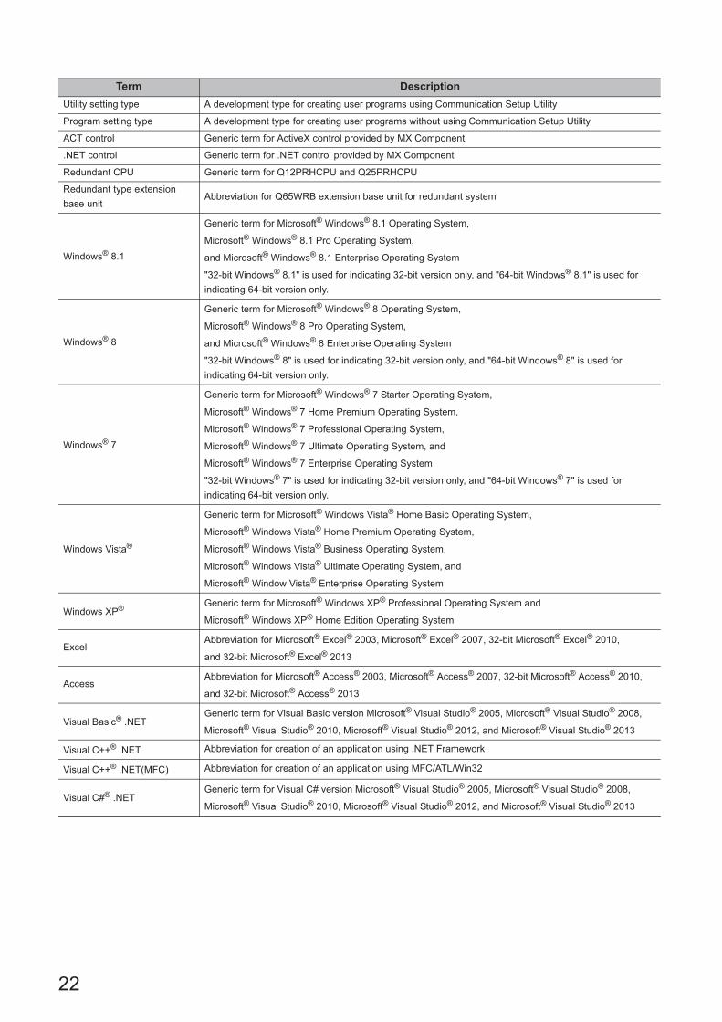
This manual uses the terms listed in the following table unless otherwise noted.
Term Description
MX ComponentGeneric product name for SWnDNC-ACT-E and SWnDNC-ACT-EA (n: version)
-EA indicates a volume-license product.
Personal computer Generic term for personal computers on which Windows® operates
PC CPU module Abbreviation for MELSEC Q series-compatible PC CPU module (CONTEC CO., LTD. product)
GX Developer
Generic product name for SWnD5C-GPPW-E, SWnD5C-GPPW-EA, SWnD5C-GPPW-EV, and
SWnD5C-GPPW-EVA (n: version)
-EA indicates a volume-license product, and -EV an updated product.
GX Works2 Generic product name for SWnDNC-GXW2 (n: version)
MT Works2 Generic product name for SWnDNC-MTW2 (n: version)
GX Simulator
Generic product name for SWnD5C-LLT-E, SWnD5C-LLT-EA, SWnD5C-LLT-EV, and SWnD5C-LLT-EVA
(n: version)
-EA means a volume-license product, and -EV an updated product.
MELSECNET/H board
Generic term for Q80BD-J71LP21-25, Q80BD-J71LP21S-25, Q81BD-J71LP21-25, Q80BD-J71LP21G,
and Q80BD-J71BR11
Abbreviation for MELSECNET/H interface board
CC-Link IE Controller Network
board
Generic term for Q80BD-J71GP21-SX and Q80BD-J71GP21S-SX
Abbreviation for CC-Link IE Controller Network interface board
CC-Link IE Field Network
boardAbbreviation for Q81BD-J71GF11-T2 CC-Link IE Field Network interface board
CC-Link boardGeneric term for Q80BD-J61BT11N and Q81BD-J61BT11
Abbreviation for CC-Link system master/local interface board
RCPU Generic term for R04, R08, R16, R32 and R120
QCPU (Q mode)
Generic term for Q00J, Q00UJ, Q00, Q00U, Q01, Q01U, Q02, Q02H, Q02PH, Q02U, Q03UD, Q03UDE,
Q03UDV, Q04UDH, Q04UDEH, Q04UDV, Q06H, Q06PH, Q06UDH, Q06UDEH, Q06UDV, Q10UDH,
Q10UDEH, Q12H, Q12PH, Q12PRH, Q13UDH, Q13UDEH, Q13UDV, Q20UDH, Q20UDEH, Q25H,
Q25PH, Q25PRH, Q26UDH, Q26UDEH, Q26UDV, Q50UDEH, and Q100UDEH
Built-in Ethernet port QCPUGeneric term for Q03UDE, Q03UDV, Q04UDEH, Q04UDV, Q06UDEH, Q06UDV, Q10UDEH, Q13UDEH,
Q13UDV, Q20UDEH, Q26UDEH, Q26UDV, Q50UDEH, and Q100UDEH
LCPU Generic term for L02S, L02, L06, L26, and L26-BT
FX5CPU Generic term for FX5U and FX5UC
FXCPUGeneric term for FX0, FX0S, FX0N, FX1, FX1N, FX1NC, FX1S, FXU, FX2C, FX2N, FX2NC, FX3S, FX3G, FX3GC, FX3U,
and FX3UC
Built-in Ethernet CPU Generic term for RCPU, built-in Ethernet port QCPU, LCPU and FX5CPU
R motion CPU Generic term for R16MT, R32MT
Q motion CPU Generic term for Q172, Q173, Q172H, Q173H, Q172D, Q173D, Q172DS, and Q173DS
QSCPU Abbreviation for a safety CPU module (QS001CPU)
C Controller moduleGeneric term for Q12DCCPU-V (Basic mode), Q12DCCPU-V (Extended mode), Q24DHCCPU-V, and
Q24DHCCPU-LS
Q12DCCPU-V
(Basic mode)
Status that Q12DCCPU-V is initialized with the basic mode
For Q12DCCPU-V (Basic mode), refer to the following manual.
C Controller Module User's Manual (Hardware Design, Function Explanation)
Q12DCCPU-V
(Extended mode)
Status that Q12DCCPU-V is initialized with the extended mode
For Q12DCCPU-V (Extended mode), refer to the following manual.
MELSEC-Q C Controller Module User's Manual
Programmable controller CPUGeneric term for RCPU, QCPU (Q mode), LCPU, FX5CPU, FXCPU, R motion CPU, Q motion CPU,
QSCPU, and C Controller module
R series-compatible C24 Generic term for RJ71C24, RJ71C24-R2, and RJ71C24-R4
Q series-compatible C24 Generic term for QJ71C24, QJ71C24-R2, QJ71C24N, QJ71C24N-R2, and QJ71C24N-R4

21
L series-compatible C24 Generic term for LJ71C24 and LJ71C24-R2
FX extended portGeneric term for FX0N-485ADP, FX2NC-485ADP, FX1N-485-BD, FX2N-485-BD, FX3G-485-BD, FX3U-485-BD,
and FX3U-485ADP
Serial communication moduleGeneric term for R series-compatible C24, Q series-compatible C24, L series-compatible C24, and FX
extended port
R series-compatible E71 Generic term for RJ71EN71
Q series-compatible E71 Generic term for QJ71E71, QJ71E71-B2, QJ71E71-B5, and QJ71E71-100
Ethernet adapter module Abbreviation for NZ2GF-ETB CC-Link IE Field Network Ethernet adapter module
Ethernet adapter/module Generic term for FX3U-ENET-ADP and FX3U-ENET(-L)
Ethernet module Generic term for R series-compatible E71 and Q series-compatible E71
CC-Link G4 module Abbreviation for AJ65BT-G4-S3 GPP function peripheral connection module
GOT Abbreviation for Graphic Operation Terminal
GOT2000 Abbreviation for Graphic Operation Terminal GOT2000 series
GOT1000 Abbreviation for Graphic Operation Terminal GOT1000 series
GOT900 Abbreviation for Graphic Operation Terminal GOT900 series
Inverter Abbreviation for FREQROL-A800 series
Robot controller Abbreviation for CR750-D/CRnD-700 series
Serial communicationAbbreviation for communication with programmable controller CPU using the serial communication
module
Ethernet communicationAbbreviation for communication by connecting the personal computer to Ethernet module or the built-in
Ethernet CPU
CPU COM communicationAbbreviation of communication performed by connecting the personal computer to the RS-232 or RS-422
connector of programmable controller CPU
CPU USB communicationAbbreviation for communication by connecting personal computer to the USB connector of Programmable
controller CPU
MELSECNET/H
communicationAbbreviation for communication with programmable controller CPU using MELSECNET/H board
CC-Link IE Controller Network
communication
Abbreviation for communication with programmable controller CPU using CC-Link IE Controller Network
board
CC-Link IE Field Network
communicationAbbreviation for communication with programmable controller CPU using CC-Link IE Field Network board
CC-Link communication Abbreviation for communication with programmable controller CPU using CC-Link board
CC-Link G4 communication Abbreviation for communication with programmable controller CPU using CC-Link G4 module
Q series bus communicationAbbreviation for communication with programmable controller CPU on the same base using PC CPU
module
GX Simulator communication Abbreviation for communication with GX Simulator
GX Simulator2 communication Abbreviation for communication using the simulation function of GX Works2
MT Simulator2 communication Abbreviation for communication using the simulation function of MT Developer2
Modem communicationAbbreviation for communication with programmable controller CPU via modems using
Q series-compatible C24, L series-compatible C24 or FXCPU
Gateway function
communication
Abbreviation for communication with programmable controller CPU and third-party programmable
controllers using the gateway functions of GOT
GOT transparent
communication
Abbreviation for communication with programmable controller CPU using the GOT transparent functions
of GOT
Inverter COM communication Abbreviation for communication by connecting the inverter to the COM port of personal computer
Inverter USB communication Abbreviation for communication by connecting the inverter to the USB port of personal computer
Robot controller COM
communicationAbbreviation for communication by connecting the robot controller to the COM port of personal computer
Robot controller USB
communicationAbbreviation for communication by connecting the robot controller to the USB port of personal computer
Robot controller Ethernet
communicationAbbreviation for communication by connecting the robot controller and personal computer to Ethernet
Term Description
22
Utility setting type A development type for creating user programs using Communication Setup Utility
Program setting type A development type for creating user programs without using Communication Setup Utility
ACT control Generic term for ActiveX control provided by MX Component
.NET control Generic term for .NET control provided by MX Component
Redundant CPU Generic term for Q12PRHCPU and Q25PRHCPU
Redundant type extension
base unitAbbreviation for Q65WRB extension base unit for redundant system
Windows® 8.1
Generic term for Microsoft® Windows® 8.1 Operating System,
Microsoft® Windows® 8.1 Pro Operating System,
and Microsoft® Windows® 8.1 Enterprise Operating System
"32-bit Windows® 8.1" is used for indicating 32-bit version only, and "64-bit Windows® 8.1" is used for
indicating 64-bit version only.
Windows® 8
Generic term for Microsoft® Windows® 8 Operating System,
Microsoft® Windows® 8 Pro Operating System,
and Microsoft® Windows® 8 Enterprise Operating System
"32-bit Windows® 8" is used for indicating 32-bit version only, and "64-bit Windows® 8" is used for
indicating 64-bit version only.
Windows® 7
Generic term for Microsoft® Windows® 7 Starter Operating System,
Microsoft® Windows® 7 Home Premium Operating System,
Microsoft® Windows® 7 Professional Operating System,
Microsoft® Windows® 7 Ultimate Operating System, and
Microsoft® Windows® 7 Enterprise Operating System
"32-bit Windows® 7" is used for indicating 32-bit version only, and "64-bit Windows® 7" is used for
indicating 64-bit version only.
Windows Vista®
Generic term for Microsoft® Windows Vista® Home Basic Operating System,
Microsoft® Windows Vista® Home Premium Operating System,
Microsoft® Windows Vista® Business Operating System,
Microsoft® Windows Vista® Ultimate Operating System, and
Microsoft® Window Vista® Enterprise Operating System
Windows XP® Generic term for Microsoft® Windows XP® Professional Operating System and
Microsoft® Windows XP® Home Edition Operating System
ExcelAbbreviation for Microsoft® Excel® 2003, Microsoft® Excel® 2007, 32-bit Microsoft® Excel® 2010,
and 32-bit Microsoft® Excel® 2013
AccessAbbreviation for Microsoft® Access® 2003, Microsoft® Access® 2007, 32-bit Microsoft® Access® 2010,
and 32-bit Microsoft® Access® 2013
Visual Basic® .NETGeneric term for Visual Basic version Microsoft® Visual Studio® 2005, Microsoft® Visual Studio® 2008,
Microsoft® Visual Studio® 2010, Microsoft® Visual Studio® 2012, and Microsoft® Visual Studio® 2013
Visual C++® .NET Abbreviation for creation of an application using .NET Framework
Visual C++® .NET(MFC) Abbreviation for creation of an application using MFC/ATL/Win32
Visual C#® .NETGeneric term for Visual C# version Microsoft® Visual Studio® 2005, Microsoft® Visual Studio® 2008,
Microsoft® Visual Studio® 2010, Microsoft® Visual Studio® 2012, and Microsoft® Visual Studio® 2013
Term Description
23
CHAPTER 1 OVERVIEW
1
1.1 Outline
of Controls
CHAPTER 1 OVERVIEW
This manual explains the procedure and the error codes when creating programs with MX Component.
1.1 Outline of Controls
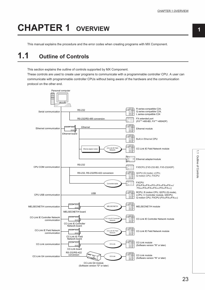
This section explains the outline of controls supported by MX Component.
These controls are used to create user programs to communicate with a programmable controller CPU. A user can
communicate with programmable controller CPUs without being aware of the hardware and the communication
protocol on the other end.
Personal computer
Serial communication
Ethernet communication
Ethernet board
MELSECNET/H board
CC-Link IE ControllerNetwork board
CC-Link IE FieldNetwork board
CC-Link boardRS-232/RS-422
conversion
CC-Link G4 module(Software version "D" or later)
Ethernet
RS-232/RS-485 conversion
RS-232, RS-232/RS-422 conversion
RS-232
USB
RS-232 R series-compatible C24,Q series-compatible C24,L series-compatible C24
FX extended port(FX***-485-BD, FX***-485ADP)
Ethernet module
Ethernet adapter/module
FX5CPU (FX5-232-BD, FX5-232ADP)
Built-in Ethernet CPU
CC-Link IE Field Network module
QCPU (Q mode), LCPU, Q motion CPU, FXCPU
RCPU, R motion CPU, QCPU (Q mode), LCPU, C Controller module, QSCPU, Q motion CPU, FXCPU (FX3S/FX3G/FX3GC)
FXCPU(FX0/FX0S/FXON/FX1S/FX1N/FX2N/FX1NC/ FX2NC/FX3S/FX3G/FX3GC/FX3U/FX3UC)
MELSECNET/H module
CC-Link IE Controller Network module
CC-Link IE Field Network module
CC-Link module(Software version "N" or later)
CC-Link module(Software version "N" or later)
CPU COM communication
CPU USB communication
MELSECNET/H communication
CC-Link IE Controller Networkcommunication
CC-Link communication
CC-Link G4 communication
CC-Link IE Field Networkcommunication
Ethernet adapter module
MELSECNET/H
CC-Link IE FieldNetwork
Converter/cable
CC-Link IE ControllerNetwork
CC-Link IE FieldNetwork
CC-Link
CC-Link

24
Personal computer
PC CPU module
GX Developer+ GX Simulator
(offline debugging)
Simulation function of GX Works2(GX Simulator2)
Built-in Ethernet CPU
QCPU (Q mode)
Ethernet module
QCPU (Q mode), C Controller module, Q motion CPU
RCPU, QCPU (Q mode), LCPU, C Controller module, Q motion CPU
GOT
R series-compatible C24, Q series-compatible C24, L series-compatible C24
FXCPU, Q series-compatible C24,L series-compatible C24
Perform communication with the specified programmable controller easily without being aware of communication protocol.
GX Developer Version 5(SW5D5C-GPPW-E) or laterGX Simulator(SW5D5C-LLT-E 10B) or later
GX Works2 Version 1(SW1DNC-GXW2-E) or later
GX Simulator communication
GX Simulator2 communication
Modem communication
Gateway function communication
GOT transparent communication
Q series bus communication
GOT
USB,RS-232Ethernet
Ethernet
Ethernet
RS-232
On the same base
RS-232
Bus connection
Sold separately
Sold separately
FXCPURS-232/RS-422
Simulation function of MT Developer2(MT Simulator2)
MT Developer2 Version 1(SW1DNC-MTW2-E) or later
Sold separatelyMT Simulator2 communication
Ethernet
Ethernet Adapter module CC-Link IE FieldNetwork CC-Link IE Field Network
Ethernet Adapter/moduleEthernet
Ethernet board
Modem Modem
Telephone line
Inverter COM communication
Inverter USB communication
Robot controllerCOM communication
Robot controllerUSB communication
Robot controllerEthernet communication
RS-232/RS-485 conversion
USB
Inverter
Inverter
RS-232
USB
Ethernet
Ethernet board
Robot controller
Robot controller
Robot controller

25
CHAPTER 1 OVERVIEW
1
1.2 Control and F
unction Lists1.2.1 C
ontrol list
1.2 Control and Function Lists
This section shows the lists of controls and functions.
1.2.1 Control list
The following tables show the controls included in each DLL supported by MX Component.
(1) ACT controlThe following table shows the ActiveX controls supported by MX Component.
Data can be accessed using devices.
(2) .NET controlThe following table shows the .NET controls supported by MX Component.
Data can be accessed using labels.
DLL name
Included control name
ApplicationFor VB, VC++,
VC#, VBAFor VBScript
ActUtlType.dll ActUtlType ActMLUtlType*1The utility setting type control which is used to create a user
program using Communication Setup Utility.
ActProgType.dll*2 ActProgType ActMLProgType*1The program setting type control which is used to create a user
program without using Communication Setup Utility.
ActSupportMsg.dll ActSupportMsg ActMLSupportMsg Used for the troubleshooting function.
*1 : Communication is disabled if the communication path is a modem.*2 : Not applicable to inverter communication/robot controller communication.
DLL nameIncluded control name
ApplicationFor VB, VC++, VC#
DotUtlType.dll DotUtlTypeThe utility setting type control which is used to create a user
program using Communication Setup Utility.
DotSupportMsg.dll DotSupportMsg Used for the troubleshooting function.

26
1.2.2 Function list
The following table shows the features of the functions and the functions that can be used for the controls.
● Considerations for using QSCPUIn order to protect the safety programmable controller system, an error code is returned when a function to write data to buffer memory, write/set devices, or write clock data is executed.
Function name Feature Refer
Open Open a communication line. Page 333, Section 5.2.1, Page 420, Section 5.3.1
Close Close a communication line. Page 335, Section 5.2.2, Page 421, Section 5.3.2
ReadDeviceBlock Read devices in bulk. (4-byte data) Page 336, Section 5.2.3, Page 422, Section 5.3.3
WriteDeviceBlock Write devices in bulk. (4-byte data) Page 340, Section 5.2.4, Page 426, Section 5.3.4
ReadDeviceRandom Read devices randomly. (4-byte data) Page 343, Section 5.2.5, Page 429, Section 5.3.5
WriteDeviceRandom Write devices randomly. (4-byte data) Page 347, Section 5.2.6, Page 434, Section 5.3.6
SetDevice Set one point of device. (4-byte data) Page 351, Section 5.2.7, Page 440, Section 5.3.7
GetDevice Acquire data of one point of device. (4-byte data) Page 353, Section 5.2.8, Page 442, Section 5.3.8
ReadBuffer Read data from buffer memory. Page 356, Section 5.2.9, Page 444, Section 5.3.9
WriteBuffer Write data to buffer memory. Page 361, Section 5.2.10, Page 446, Section 5.3.10
GetClockData Read clock data from programmable controller CPU. Page 366, Section 5.2.11, Page 448, Section 5.3.11
SetClockData Write clock data to programmable controller CPU. Page 371, Section 5.2.12, Page 450, Section 5.3.12
GetCpuType Read programmable controller CPU model. Page 376, Section 5.2.13, Page 452, Section 5.3.13
SetCpuStatusRemote RUN/STOP/PAUSE of programmable controller
CPU.Page 381, Section 5.2.14, Page 453, Section 5.3.14
EntryDeviceStatus Register device status monitor. Page 385, Section 5.2.15, Page 454, Section 5.3.15
FreeDeviceStatus Deregister device status monitor. Page 390, Section 5.2.16, Page 457, Section 5.3.16
OnDeviceStatus Announce event. Page 391, Section 5.2.17, Page 458, Section 5.3.17
ReadDeviceBlock2 Read devices in bulk. (2-byte data) Page 394, Section 5.2.18, Page 460, Section 5.3.18
WriteDeviceBlock2 Write devices in bulk. (2-byte data) Page 397, Section 5.2.19, Page 463, Section 5.3.19
ReadDeviceRandom2 Read devices randomly. (2-byte data) Page 400, Section 5.2.20, Page 467, Section 5.3.20
WriteDeviceRandom2 Write devices randomly. (2-byte data) Page 404, Section 5.2.21, Page 472, Section 5.3.21
SetDevice2 Set one point of device. (2-byte data) Page 408, Section 5.2.22, Page 477, Section 5.3.22
GetDevice2 Acquire data of one point of device. (2-byte data) Page 411, Section 5.2.23, Page 479, Section 5.3.23
Connect Connect a telephone line. Page 414, Section 5.2.24, Page 481, Section 5.3.24
Disconnect Disconnect a telephone line. Page 416, Section 5.2.25, Page 483, Section 5.3.25
GetErrorMessage Display error definition and corrective action. Page 418, Section 5.2.26, Page 485, Section 5.3.26
27
CHAPTER 2 CONTROLS
2
2.1 Settings for U
sing Con
trols2.1.1 W
hen using V
BA
CHAPTER 2 CONTROLS
This chapter explains settings for using controls, programming procedure, device types, and applicable access ranges.
2.1 Settings for Using Controls
This section explains the settings for using controls.
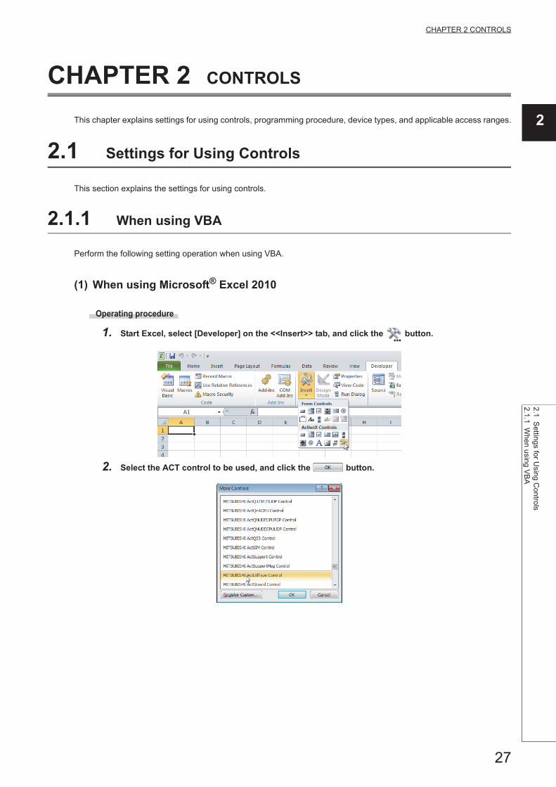
2.1.1 When using VBA
Perform the following setting operation when using VBA.
(1) When using Microsoft® Excel 2010
Operating procedure
1. Start Excel, select [Developer] on the <<Insert>> tab, and click the button.
2. Select the ACT control to be used, and click the button.

28
3. Paste the selected ACT control to the sheet.
4. Select [Visual Basic] on the <<Developer>> tab to start Visual Basic Editor.
5. Create a program with Visual Basic Editor.
29
CHAPTER 2 CONTROLS
2
2.1 Settings for U
sing Con
trols2.1.1 W
hen using V
BA
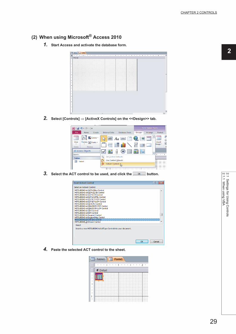
(2) When using Microsoft® Access 2010
1. Start Access and activate the database form.
2. Select [Controls] [ActiveX Controls] on the <<Design>> tab.
3. Select the ACT control to be used, and click the button.
4. Paste the selected ACT control to the sheet.

30
5. Select [View Code] on the <<Design>> tab to start Visual Basic Editor.
6. Create a program with Visual Basic Editor.

31
CHAPTER 2 CONTROLS
2
2.1 Settings for U
sing Con
trols2.1.2 W
hen using V
BS
cript
2.1.2 When using VBScript
Create HTML or ASP using a tool such as notepad, commercially available text editor, or HTML creation tool.
For the grammars of HTML and ASP, refer to the commercially available references.
The HTML and ASP sample programs installed with MX Component can also be referred.

32
2.1.3 When Using Visual Studio® .NET
Perform the following setting operation when using Visual Studio® .NET.
(1) Setting the include file (for Visual Basic® .NET)
Operating procedure
1. Start the project and select [Project] [Add Existing Item].
2. Select the ActDefine.vb file and click the button.
The ActDefine.vb file is stored in the following folder at the time of installation.
<User-specified folder> - <Act> - <Include>
3. The ActDefine.vb file is displayed on the Solution Explorer window.

33
CHAPTER 2 CONTROLS
2
2.1 Settings for U
sing Con
trols2.1.3 W
hen U
sing Visua
l Studio
® .N
ET
(2) Setting the include file (for Visual C++® .NET)
Operating procedure
1. Start Visual Studio® .NET and select [Project] [Property].*1
*1 : For Visual Studio® 2005 and Visual Studio® 2008, select [Tools] [Options].
2. Select [Configuration Properties] [VC++ Directories] on the navigation pane displayed on the
left side of the screen.*2
*2 : For Visual Studio® 2005 and Visual Studio® 2008, select [Projects and Solutions] [VC++ Directories].
3. Right-click on "Include Directories" displayed on the right side of the screen and select <Edit...>.*3
*3 : For Visual Studio® 2005 and Visual Studio® 2008, select "Include files" for "Shows directories for:" on the top right of the screen.

34
4. Click (New line).
5. Click .
6. Select the folder that contains the Include files.
The include files are stored in the following folder at the time of installation.
<User-specified folder> - <Act> - <Include>

35
CHAPTER 2 CONTROLS
2
2.1 Settings for U
sing Con
trols2.1.3 W
hen U
sing Visua
l Studio
® .N
ET
(3) Setting the include file (for Visual C#® .NET)
Operating procedure
1. Start Visual Studio®.NET and select [Project] [Add Existing Item].
2. Select the ActDefine.cs file and click the button.
The ActDefine.cs file is stored in the following folder at the time of installation.
<User-specified folder> - <Act> - <Include>
3. The ActDefine.cs file is displayed on the Solution Explorer window.

36
(4) When pasting a control to the form
(Common setting for Visual C++® .NET, Visual Basic® .NET, and Visual C#® .NET projects)
Operating procedure
1. Select [Tools] [Choose Toolbox Items].
2. Select the <<.NET Framework Components>> tab (for pasting .NET control) or the <<COM
Components>> tab (for pasting ACT control), select the control to be used, and click the
button.
3. The control is added to the bottom of the tab selected under "Toolbox".

37
CHAPTER 2 CONTROLS
2
2.1 Settings for U
sing Con
trols2.1.3 W
hen U
sing Visua
l Studio
® .N
ET
● When creating an application using .NET Framework 4 or .NET Framework 4.5Add an application configuration file with the following elements (app.config) to the folder which contains the .exe file of the application.
For details, refer to Visual Studio® Help.
(5) When using control without pasting it to a form (Reference setting)
(Common setting for Visual C++® .NET, Visual Basic® .NET, and Visual C#® .NET projects)
Operating procedure
1. Select [View] [Solution Explorer] to display "Solution Explorer".
2. Right-click the project and select "Reference".*1
*1 : For Visual Studio® 2010 or Visual Studio® 2012, select "Add Reference". (To Step 4)
For Visual Studio® 2013, select "Add" "References". (To Step 4)
3. Select the button on "Property Pages".
<configuration>
<startup useLegacyV2RuntimeActivationPolicy="true">
<supportedRuntime version="v4.0"/>
</startup>
</configuration>

38
4. Select the <<COM>> tab (for pasting ACT control) or the <<.NET>> tab (for pasting .NET control),
select the control to be used, and click the button.*1
*1 : For Visual Studio® 2012 or Visual Studio® 2013, select "COM" "Type Libraries" (for pasting ACT control) or
"Assemblies" "Extensions" (for pasting .NET control), select the control to be used, and click the button.

39
CHAPTER 2 CONTROLS
2
2.1 Settings for U
sing Con
trols2.1.3 W
hen U
sing Visua
l Studio
® .N
ET
5. The library of the component to be used is set to "References" as a reference.
The library of the component to be used can be checked with "References" on "Class View".
(For Visual Studio® 2008 and Visual Studio® 2010, enable "Show Project References" in "Class View
Settings".)

40
6. For Visual Basic® .NET of Visual Studio® 2010/2012/2013, click on "Solution Explorer" to
display all files.
Right-click the library of the component to be used under "References" and select "Properties".
Set "False" for "Embed Interop Types".
● When using .NET ControlThe following library is added to "References".
• For DotUtlType: ActTypeLib • For DotSupportMsg: ActSupportMsgLib
Set "False" for "Embed Interop Types" in the property of each library.
● When creating an application using .NET Framework 4 or .NET Framework 4.5Add an application configuration file with the following elements (app.config) to the folder which contains the .exe file of the application.
For details, refer to Visual Studio® Help.
<configuration>
<startup useLegacyV2RuntimeActivationPolicy="true">
<supportedRuntime version="v4.0"/>
</startup>
</configuration>

41
CHAPTER 2 CONTROLS
2
2.1 Settings for U
sing Con
trols2.1.3 W
hen U
sing Visua
l Studio
® .N
ET
(6) When using ACT control on Visual C++® .NET(MFC)
Operating procedure
1. Right-click the form and select "Insert ActiveX Control".
2. Select the ACT control to be used and click the button.
3. The selected ACT control is pasted to the form.
4. Right-click the form and select "Add Variable".

42
5. After selecting "Control variable", select the ID of the ACT control for "Control ID", enter the
variable name, and click the button.
6. Check that the member variable set in Step 5 is created.
• In the form class of Class View
• In the header file of form class

43
CHAPTER 2 CONTROLS
2
2.2 Program
ming P
rocedure2.2.1 W
hen using V
BA
2.2 Programming Procedure
This section explains the procedure to create a user application.
When creating a user program, select "x86" (32 bits) for "Target CPU".
2.2.1 When using VBA
Create a user application with the following procedure when using VBA.
*1 : MX Component Version 4 Operating Manual
Power on the personal computer and start Windows .
Install MX Component Version 4.
Select the setting type.
Start Communication Setup Utility and set the communicationsettings by following the instructions of wizard.
Start Excel or Access.
Start Visual Basic Editor and createan application.
Form the controls to be usedin VBA. (ActUtlType)
Set the property of the formed controls.(Set the logical station number only.)
Create a program using the functions supported bycorresponding controls.
Start Excel or Access.
Start Visual Basic Editor and createan application.
Form the controls to be usedin VBA. (ActProgType)
Set the property of the formed controls.
Program setting type
Utility setting type
R
*1
*1
*1
*1
Debug the program using PLC Monitor Utility.*1
Completion of user application
Page 27,
Section 2.1.1
Page 27,
Section 2.1.1
Page 54, CHAPTER 3, Page 69, CHAPTER 4, Page 329, CHAPTER 5

44
2.2.2 When using VBScript
Create a user application with the following procedure when using VBScript.
*1 : MX Component Version 4 Operating Manual
Power on the personal computer and start Windows .
Install MX Component Version 4.
Select the setting type.
Start Communication Setup Utility and set the communicationsettings by following the instructions of wizard.
Create a website using the text editorand the HTML editor.
Set the property of the formed controls.(Set the logical station number only.)
On the website, form the controls forMX Component controls to be used inVBScript. (ActUtlType)
On the website, form the controls forMX Component controls to be used inVBScript. (ActProgType)
Create a program using the functions supported bycorresponding controls.
Create a website using the text editorand the HTML editor.
Set the property of the formed controls.
Program setting type
Utility setting type
R
*1
*1
*1
*1
Debug the program using PLC Monitor Utility.*1
Completion of user application
Page 31,
Section 2.1.2
Page 31,
Section 2.1.2
Page 54, CHAPTER 3, Page 69, CHAPTER 4, Page 329, CHAPTER 5

45
CHAPTER 2 CONTROLS
2
2.2 Program
ming P
rocedure2.2.3 W
hen using V
isual Basic
® .N
ET
2.2.3 When using Visual Basic® .NET
Create a user application with the following procedure when using Visual Basic® .NET.
*1 : MX Component Version 4 Operating Manual*2 : Page 32, Section 2.1.3 (1)
Power on the personal computer and start Windows .
Install MX Component Version 4.
Select the setting type.
Start Communication Setup Utility and set the communicationsettings by following the instructions of wizard.
Start Visual Basic .NET.
Add controls to Visual Basic .NET.
Create a form and paste the controls.(ActUtlType)
Set the property (logical station number)of the pasted controls.
Create a program using the functions supported bycorresponding controls.
Program setting type
Utility setting type
Use labels.
Start Communication Setup Utility and set the communicationsettings by following the instructions of wizard.
Start Label Utility, and create andregister labels.
Start Visual Basic .NET.
Add controls to Visual Basic .NET.
Create a form and paste the controls.(DotUtlType)
Set the property (logical station number)of the pasted controls.
*1
Add controls to Visual Basic .NET.
Start Visual Basic .NET.
Create a form and paste the controls.(ActProgType)
Set the property of the pasted controls.
Yes
No
R
R
RR
R
R
R
*2
*1
*1 *1
*1
*2
*2
*1
Debug the program using PLC Monitor Utility.*1
Completion of user application
Page 54, CHAPTER 3, Page 69, CHAPTER 4, Page 329, CHAPTER 5

46
2.2.4 When using Visual C++® .NET
Create a user application with the following procedure when using Visual C++® .NET.
*1 : MX Component Version 4 Operating Manual*2 : Page 33, Section 2.1.3 (2)
When using both .NET control (DotUtlType) and Act control (ActUtlType) by pasting them, perform the following operations by selecting [Project] - [Property] from Solution Explorer.
• Visual Studio® 2005/20081) Select [Common Properties]-[References].2) Select "ActUtlTypeLib" from "Name" in "References", and change the setting of "Use" under "Build Properties" to "False". 3) Select "ActInterop.ActUtlTypeLib.1.0" from "Name" in "References", and change the setting of "Use" under "Build Properties" to "False". 4) Click the [OK] button to reflect the change of the setting.
• Visual Studio® 2010/2012/20131) Select [Common Properties]-[Framework and references].2) Select "ActUtlTypeLib" from "Name" in "References", and change the setting of "Reference Assembly Output" under "Build Properties" to "False".3) Select "Interop.ActUtlTypeLib.1.0" from "Name" in "References", and change the setting of "Reference Assembly Output" under "Build Properties" to "False".4) Click the [OK] button to reflect the change of the setting.
Power on the personal computer and start Windows .
Install MX Component Version 4.
Select the setting type.
Start Communication Setup Utility and set the communication settings by following the instructions of wizard.
Start Visual C++ .NET.
Add controls to Visual C++ .NET.
Create a form and paste the controls.(ActUtlType)
Define the pasted controls as dialogmembers using Class Wizard.
Create a program using the functions supported bycorresponding controls.
Program setting type
Utility setting type
Use labels.
Set the property (logical station number)of the pasted controls.
Start Communication Setup Utility and set the communicationsettings by following the instructions of wizard.
Start Label Utility, and create andregister labels.
Start Visual C++ .NET.
Add controls to Visual C++ .NET.
Create a form and paste the controls.(DotUtlType)
Define the pasted controls as dialogmembers using Class Wizard.
Set the property (logical station number)of the pasted controls.
*1
*1
*1
Add controls to Visual C++ .NET.
Define the pasted controls as dialogmembers using Class Wizard.
Start Visual C++ .NET.
Create a form and paste the controls.(ActProgType)
Yes
No
R
R
R
R
R
R
R
Set the property of the pasted controls.
*2
*2
*1
*1
*2
*1
Debug the program using PLC Monitor Utility.*1
Completion of user application
Page 54, CHAPTER 3, Page 69, CHAPTER 4, Page 329, CHAPTER 5

47
CHAPTER 2 CONTROLS
2
2.2 Program
ming P
rocedure2.2.5 W
hen using V
isual C#
® .N
ET
2.2.5 When using Visual C#® .NET
Create a user application with the following procedure when using Visual C#® .NET.
*1 : MX Component Version 4 Operating Manual*2 : Page 35, Section 2.1.3 (3)
On Visual Studio® 2010/2012/2013, when using both .NET control (DotUtlType) and Act control (ActUtlType) by pasting them, perform the following operations by selecting "References" from Solution Explorer.
1) Select ActUtlTypeLib and delete it.2) Select Interop.ActUtlTypeLib and delete it.
Power on the personal computer and start Windows .
Install MX Component Version 4.
Select the setting type.
Start Communication Setup Utility and set the communicationsettings by following the instructions of wizard.
Start Visual C# .NET.
Add controls to Visual C# .NET.
Create a form and paste the controls.(ActUtlType)
Set the property (logical station number)of the pasted controls.
Create a program using the functions supported bycorresponding controls.
Program setting type
Utility setting type
Use labels.
Start Communication Setup Utility and set the communicationsettings by following the instructions of wizard.
Start Label Utility, and create andregister labels.
Start Visual C# .NET.
Add controls to Visual C# .NET.
Create a form and paste the controls.(DotUtlType)
Set the property (logical station number)of the pasted controls.
*1
*1
Add controls to Visual C# .NET.
Start Visual C# .NET.
Create a form and paste the controls.(ActProgType)
Set the property of the pasted controls.
Yes
No
R
R
R R
R
R
R
*2
*1
*1 *1
*2
*2
*1
Debug the program using PLC Monitor Utility.*1
Completion of user application
Page 54, CHAPTER 3, Page 69, CHAPTER 4, Page 329, CHAPTER 5

48
2.3 Device Types
This section explains the devices that can be specified for functions.
● Specify devices with "device name + device number" for any of the following functions.For the device numbers, note the differences between octal, decimal, and hexadecimal numbers.Target functions: ReadDeviceBlock, ReadDeviceBlock2, WriteDeviceBlock, WriteDeviceBlock2, ReadDeviceRandom, ReadDeviceRandom2, WriteDeviceRandom, WriteDeviceRandom2, SetDevice, SetDevice2, GetDevice, GetDevice2
● When specifying bit devices for ReadDeviceBlock, ReadDeviceBlock2, WriteDeviceBlock, or WriteDeviceBlock2, specify the device number with a multiple of 16.
● Local devices and file registers per program of programmable controller CPU cannot be accessed by specifying a program name.
● Only the devices indicated in this section are supported. Do not use unsupported devices.
(1) Common device types (except for communication to FX5CPU, gateway
function communication, inverter communication, and robot controller
communication)The following device types are common to all communication paths except for the communication to FX5CPU,
gateway function communication, inverter communication, and robot controller communication.
Device Device name Device type Device number
Function input FX Bit device Decimal
Function output FY Bit device Decimal
Function register FD Word device*1 Decimal
Special relay SM Bit device Decimal
Special register SD Word device Decimal
Input relay X Bit device Hexadecimal*2
Output relay Y Bit device Hexadecimal*2
Internal relay M Bit device Decimal
Latch relay L Bit device Decimal
Annunciator F Bit device Decimal
Edge relay V Bit device Decimal
Link relay B Bit device Hexadecimal
Data register D Word device Decimal
Link register W Word device Hexadecimal
Timer*12
Contact TS Bit device Decimal
Coil TC Bit device Decimal
Present value TN Word device Decimal
Counter*12
Contact CS Bit device Decimal
Coil CC Bit device Decimal
Present value*3 CN Word device Decimal
Retentive timer*12
Contact STS/SS Bit device Decimal
Coil STC/SC Bit device Decimal
Present value STN/SN Word device Decimal
Link special relay SB Bit device Hexadecimal

49
CHAPTER 2 CONTROLS
2
2.3 Device
Types
*1 : 4 words/1 point. For a bulk operation, the operation is performed continuously in units of one word. For a random operation, only the first one word is read.
*2 : For FXCPU, the device number is octal.*3 : For FXCPU, the value higher than or equal to 200 is 32-bit data.*4 : These devices cannot be used when E71 is relayed.*5 : When accessing FX series CPU other than FX3G(C)CPU and FX3U(C)CPU, specify the data register (D).
The extended file register (R) can be specified only when accessing FX3G(C)CPU or FX3U(C)CPU.*6 : For specifying an extended file register, enter "\" between the block number and the file register.
When specifying R**, R of the block No. 0 becomes a target.When specifying ER0\R**, an error is returned.When specifying ER**\R**, the extension representation (indirect specification, digit specification) is not applicable.
*7 : For a direct specification, enter "\" between the direct specification and the device specification.*8 : J* specifies a network number.*9 : U* specifies a special module I/O number (hexadecimal), and G** specifies a buffer memory address (decimal).
(Example: When the special module I/O number is 200H and the buffer memory address is 100, the device name will be "U20\G100".)
*10 : In a QCPU multiple CPU configuration, an error occurs if the shared memory of the host QCPU is specified.Regardless of whether the CPU is a host CPU or other CPU, an error occurs if data is written to the shared memory.
*11 : For FXCPU, this device name can be used on FX3U(C)CPU only.*12 : When accessing the device using a label of system label Ver.2, the label of system label Ver.2 which is corresponding to
a device for contact/coil/present value is required to be defined.
Link special register SW Word device Hexadecimal
Step relay S Bit device Decimal
Accumulator A *4 Word device Decimal
Index registerZ *4 Word device Decimal
V *4 Word device Decimal
File registerR *5 Word device Decimal
ZR Word device Decimal
Extended file register ER*\R *6 Word device Decimal
Direct link *8
Link input J*\X *7 Bit device Hexadecimal
Link output J*\Y *7 Bit device Hexadecimal
Link relay J*\B *7 Bit device Hexadecimal
Link special relay J*\SB *7 Bit device Hexadecimal
Link register J*\W *7 Word device Hexadecimal
Link special register J*\SW *7 Word device Hexadecimal
Special direct buffer memory *9,*10 U*\G** *7,*11 Word device Hexadecimal/Decimal
Device Device name Device type Device number

50
(2) When access target is RCPUThe devices described in the following table can be used when access target is RCPU.
*1 : When accessing the device using a label of system label Ver.2, the label of system label Ver.2 which is corresponding to a device for contact/coil/present value is required to be defined.
(3) When access target is R motion CPU and Q motion CPUThe devices described in the following table can be used only when the access target is an R motion CPU or a Q
motion CPU.
Device Device name Device type Device number
Long timer*1
Contact LTS Bit device Decimal
Coil LTC Bit device Decimal
Present value LTN Double word device Decimal
Long counter*1
Contact LCS Bit device Decimal
Coil LCC Bit device Decimal
Present value LCN Double word device Decimal
Retentive long timer*1
Contact LSTS/LSS Bit device Decimal
Coil LSTC/LSC Bit device Decimal
Present value LSTN/LSN Double word device Decimal
Long index register LZ Double word device Decimal
Refresh device for modules RD Word device Decimal
Device Device name Device type Device number
Motion registers # Word device Decimal

51
CHAPTER 2 CONTROLS
2
2.3 Device
Types
(4) When access target is FX5CPUThe devices described in the following table can be used when access target is FX5CPU.
Device Device name Device type Device number
Special relay SM Bit device Decimal
Special register SD Word device Decimal
Input relay X Bit device Octal
Output relay Y Bit device Octal
Internal relay M Bit device Decimal
Latch relay L Bit device Decimal
Annunciator F Bit device Decimal
Edge relay V Bit device Decimal
Link relay B Bit device Hexadecimal
Data register D Word device Decimal
Link register W Word device Hexadecimal
Timer
Contact TS Bit device Decimal
Coil TC Bit device Decimal
Present value TN Word device Decimal
Counter
Contact CS Bit device Decimal
Coil CC Bit device Decimal
Present value CN Word device Decimal
Retentive timer
Contact STS/SS Bit device Decimal
Coil STC/SC Bit device Decimal
Present value STN/SN Word device Decimal
Long counter
Contact LCS Bit device Decimal
Coil LCC Bit device Decimal
Present value LCN Double word device Decimal
Link special relay SB Bit device Hexadecimal
Link special register SW Word device Hexadecimal
Step relay S Bit device Decimal
Index register Z Word device Decimal
File register R Word device Decimal
Long index register LZ Double word device Decimal
Module access device U*\G Word device Decimal

52
(5) For CC-Link communicationThe devices described in the following table can be used when accessing to the own board with CC-Link
communication.
These devices cannot be used for other communication paths.
(6) For gateway function communicationThis section explains how to specify the device name used for gateway function communication.
For specifying devices used for other communication, refer to the following manual.
MX Component Version 4 Operating Manual
(7) For inverter communication/robot controller communicationFor monitor types used for inverter communication/robot controller communication, refer to the following manual.
MX Component Version 4 Operating Manual
DeviceDevice
name
Device
type
Device
numberRemarks
Special relay SM Bit device Decimal Special relay of own board
Special register SD Word device Decimal Special register of own board
Link special relay (for CC-Link) SB Bit device Hexadecimal Link special relay of own board
Link special register (for CC-Link) SW Word device Hexadecimal Link special register of own board
Remote input X Bit device Hexadecimal RX
Remote output Y Bit device Hexadecimal RY
Link register W Word device Hexadecimal –
Remote register (Data write area for CC-Link) WW Word device Hexadecimal RWw
Remote register (Data read area for CC-Link) WR Word device Hexadecimal RWr
Buffer memory ML Word device Hexadecimal Buffer memory of own station CC-Link module
Random access buffer MC Word device HexadecimalRandom access buffer in buffer memory of own
station CC-Link module
Automatic refresh buffer MF Bit device HexadecimalAutomatic refresh buffer of own station CC-Link
module
Device Device name Device type Device number
Gateway device*1 EG Word device Decimal
*1 : If a gateway device to which a programmable controller CPU device is not assigned is read, the read data becomes 0.

53
CHAPTER 2 CONTROLS
2
2.4 Acce
ssible R
anges
(8) Device extension representationsThe following table shows applicability of device extension representation.
These representations cannot be used for ReadDeviceBlock and WriteDeviceBlock.
2.4 Accessible Ranges
For the ranges that can be accessed in each communication, refer to the following manual.
MX Component Version 4 Operating Manual
Device extension
representation
Target CPU
RCPU R motion CPU FX5CPU
Digit specification (Example: K4M0) *1
Bit specification (Example: D0.1) *2
Index setting (Example: M100Z0) *3
Device extension
representation
Target CPU
QCPU
(Q mode)
C Controller
moduleLCPU QSCPU FXCPU
Q motion
CPU
Digit specification (Example: K4M0)*4 *6
Bit specification (Example: D0.1) *7 *7 *7 *7
Index setting (Example: M100Z0)*5
Device extension
representationGOT Inverter robot controller
Digit specification (Example: K4M0)*4
Bit specification (Example: D0.1)
Index setting (Example: M100Z0)*5
: Applicable : Not applicable
*1 : FX/FY, FD/SD, V, CT/C/ST, LT/LC/LST, W/SW, G, Z, R/ZR and LZ cannot be specified.*2 : Z, T/C/ST, LT/LC/LST and LZ cannot be specified.*3 : FX/F, Z and LZ cannot be specified.*4 : FX/FX, DX/DY, and T/C/ST (contact, coil) cannot be specified.*5 : FX/FX, DX/DY, T/C/ST (contact, coil), Z, and S cannot be specified.*6 : The bit devices, whose device numbers are multiple of 16, can only be used for digit specification.
(For link direct devices, the digit specification only for K4 and K8 is supported.)*7 : Z, V, and T/C/ST (present value) cannot be specified.

54
CHAPTER 3 PROPERTIES OF CONTROLS
This chapter explains the details of properties of the controls.
3.1 Property List
The following table shows the properties of each control.
Control name Property name
ACT Control
ActUtlType
ActMLUtlType
ActLogicalStationNumber
ActPassword
ActProgType
ActMLProgType
ActATCommand*1
ActATCommandPasswordCancelRetryTimes*1
ActATCommandResponseWaitTime*1
ActBaudRate
ActCallbackCancelWaitTime*1
ActCallbackDelayTime*1
ActCallbackNumber*1
ActCallbackReceptionWaitingTimeOut*1
ActConnectionCDWaitTime*1
ActConnectionModemReportWaitTime*1
ActConnectUnitNumber
ActConnectWay*1
ActControl
ActCpuTimeOut
ActCpuType
ActDataBits
ActDestinationIONumber
ActDestinationPortNumber
ActDialNumber*1
ActDidPropertyBit
ActDisconnectionCDWaitTime*1
ActDisconnectionDelayTime*1
ActDsidPropertyBit
ActHostAddress
ActIntelligentPreferenceBit
ActIONumber
ActLineType*1
ActMultiDropChannelNumber
ActMxUnitSeries*2
ActNetworkNumber
ActOutsideLineNumber*1
ActPacketType
ActParity
ActPassword

55
CHAPTER 3 PROPERTIES OF CONTROLS
3
3.1 Property List
*1 : A property for modem communication. It can only be used for ActProgType.*2 : The property value is set automatically, and it cannot be changed.
ACT Control
ActProgType
ActMLProgType
ActPasswordCancelResponseWaitTime*1
ActPortNumber
ActProtocolType
ActSourceNetworkNumber
ActSourceStationNumber
ActStationNumber
ActStopBits
ActSumCheck
ActTargetSimulator
ActThroughNetworkType
ActTimeOut
ActTransmissionDelayTime*1
ActUnitNumber
ActUnitType
ActSupportMsg
ActMLSupportMsg–
.NET ControlDotUtlType
ActLogicalStationNumber
ActPassword
DotSupportMsg –
Control name Property name

56
3.2 Details of Control Properties
This section explains the details of properties set when creating a user application.
(1) Properties of utility setting type controlsThe following table shows the properties of the Act(ML)UtlType control and the DotUtlType control.
(2) Properties of program setting type controlsThe following table shows the properties of the Act(ML)ProgType control.
Property name
(Type)Description Default value
ActLogicalStation
Number (LONG)
A logical station number set in Communication Setup Utility.
(Applicable setting range: 0 to 1023)0(0x00)
ActPassword
(BSTR)Specify a password to disable the password set to the password protected modules.*1, *2, *3
This setting is ignored when a password protected module is not used.Empty
*1 : The setting of ActPassword is not necessary if a password is not set.*2 : Characters exceeded the maximum number of characters for the password are ignored.*3 : If a characters other than alphanumeric is specified, a character code conversion error (0xF1000001) occurs at the execution of the
Open function.
Property name
(Type)Description Default value
ActMxUnitSeries
(LONG)
Specify the series of connection target module.
The property value is set automatically, and it cannot be changed.
0(0x00)
ActNetworkNumber
(LONG)
Specify the network number for MELSECNET/H.
(Specify "0" (0x00) when specifying the host station.)
Specify the network number for accessing other station with GX Simulator.
Specify the following value for the multi-drop connection (via Q series-compatible C24,
QJ61BT11).
0(0x00)
Property value Description
0 (0x00)Specify programmable controller/motion
controller/GOT.
1 (0x01) Specify inverter.
2 (0x02) Specify robot controller.
Property value of
ActIntelligentPreferenceBit Description
0 (0x00) Specify the own network.
1 (0x01) Specify another network of multi-drop destination.

57
CHAPTER 3 PROPERTIES OF CONTROLS
3
3.2 Details of C
ontrol Properties
ActStationNumber
(LONG)
Specify the station number for MELSECNET/H or CC-Link.
(Specify "255" (0xFF) when specifying the host station.)
Specify the station number for accessing other station with GX Simulator.
Specify the following value for the multi-drop connection (via Q series-compatible C24,
QJ61BT11).
For inverter communication, specify the inverter station number (0 to 31) to be connected.
255(0xFF)
ActUnitNumber
(LONG)
Specify the module number of the serial communication module or the station number when
the target is the Q series-compatible intelligent function module.
This setting is invalid when the target is not a serial communication or Q series-compatible
intelligent function module.
For multi-drop link, specify the module number of the target serial communication module.
0(0x00)
ActConnectUnit
Number (LONG)
Specify the module number of serial communication module, QE71, or Q series-compatible
E71.
For multi-drop link, specify the module number of the requesting serial communication module.
For multi-drop link via CPU COM communication, however, the module number of the
requesting station is not required. (Specify "0" (00x0))
Specify "0" (0x00) for other than multi-drop link.
For QE71 and Q series-compatible E71, specify the relay target station number. (Fixed to "0"
(0x00) for access within the own network)
For access to another network via MELSECNET/10, specify the station number set in the
parameter of the connected Ethernet module.
0(0x00)
ActIONumber
(LONG)
Specify the module I/O number.
For multi-drop link or intelligent function module access, specify the actual I/O number (start I/
O number divided by 16) of the target serial communication module or intelligent function
module. (For multi-drop link, specify the I/O number of the relayed or requesting station)
Specify "1023" (0x3FF) when making access to another station via the host station CPU or
network.
1023(0x3FF)
Property name
(Type)Description Default value
Property value of
ActIntelligentPreferenceBitDescription
0 (0x00) Specify the own network.
1 (0x01) Specify another network of multi-drop destination.
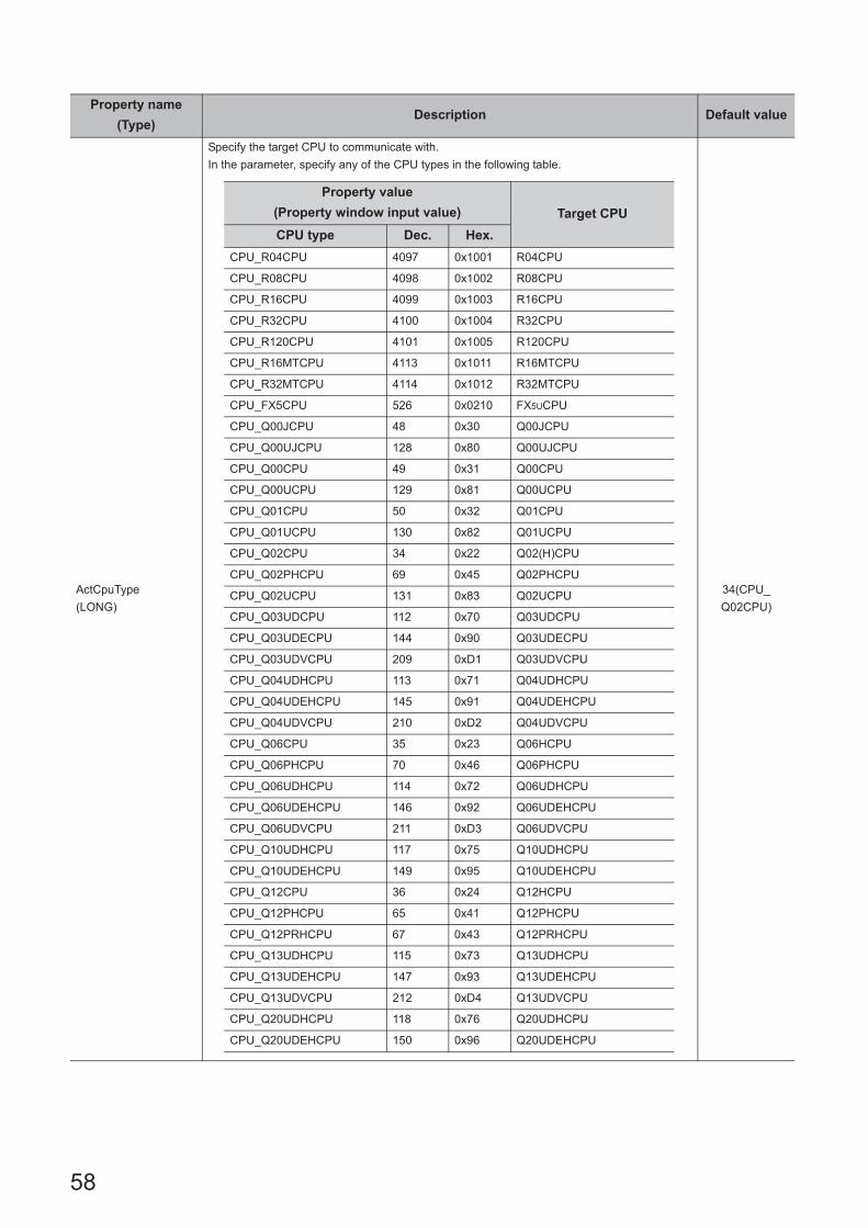
58
ActCpuType
(LONG)
Specify the target CPU to communicate with.
In the parameter, specify any of the CPU types in the following table.
34(CPU_
Q02CPU)
Property name
(Type)Description Default value
Property value
(Property window input value) Target CPU
CPU type Dec. Hex.
CPU_R04CPU 4097 0x1001 R04CPU
CPU_R08CPU 4098 0x1002 R08CPU
CPU_R16CPU 4099 0x1003 R16CPU
CPU_R32CPU 4100 0x1004 R32CPU
CPU_R120CPU 4101 0x1005 R120CPU
CPU_R16MTCPU 4113 0x1011 R16MTCPU
CPU_R32MTCPU 4114 0x1012 R32MTCPU
CPU_FX5CPU 526 0x0210 FX5UCPU
CPU_Q00JCPU 48 0x30 Q00JCPU
CPU_Q00UJCPU 128 0x80 Q00UJCPU
CPU_Q00CPU 49 0x31 Q00CPU
CPU_Q00UCPU 129 0x81 Q00UCPU
CPU_Q01CPU 50 0x32 Q01CPU
CPU_Q01UCPU 130 0x82 Q01UCPU
CPU_Q02CPU 34 0x22 Q02(H)CPU
CPU_Q02PHCPU 69 0x45 Q02PHCPU
CPU_Q02UCPU 131 0x83 Q02UCPU
CPU_Q03UDCPU 112 0x70 Q03UDCPU
CPU_Q03UDECPU 144 0x90 Q03UDECPU
CPU_Q03UDVCPU 209 0xD1 Q03UDVCPU
CPU_Q04UDHCPU 113 0x71 Q04UDHCPU
CPU_Q04UDEHCPU 145 0x91 Q04UDEHCPU
CPU_Q04UDVCPU 210 0xD2 Q04UDVCPU
CPU_Q06CPU 35 0x23 Q06HCPU
CPU_Q06PHCPU 70 0x46 Q06PHCPU
CPU_Q06UDHCPU 114 0x72 Q06UDHCPU
CPU_Q06UDEHCPU 146 0x92 Q06UDEHCPU
CPU_Q06UDVCPU 211 0xD3 Q06UDVCPU
CPU_Q10UDHCPU 117 0x75 Q10UDHCPU
CPU_Q10UDEHCPU 149 0x95 Q10UDEHCPU
CPU_Q12CPU 36 0x24 Q12HCPU
CPU_Q12PHCPU 65 0x41 Q12PHCPU
CPU_Q12PRHCPU 67 0x43 Q12PRHCPU
CPU_Q13UDHCPU 115 0x73 Q13UDHCPU
CPU_Q13UDEHCPU 147 0x93 Q13UDEHCPU
CPU_Q13UDVCPU 212 0xD4 Q13UDVCPU
CPU_Q20UDHCPU 118 0x76 Q20UDHCPU
CPU_Q20UDEHCPU 150 0x96 Q20UDEHCPU

59
CHAPTER 3 PROPERTIES OF CONTROLS
3
3.2 Details of C
ontrol Properties
ActCpuType
(LONG)
34(CPU_
Q02CPU)
Property name
(Type)Description Default value
Property value
(Property window input value) Target CPU
CPU type Dec. Hex.
CPU_Q25CPU 37 0x25 Q25HCPU
CPU_Q25PHCPU 66 0x42 Q25PHCPU
CPU_Q25PRHCPU 68 0x44 Q25PRHCPU
CPU_Q26UDHCPU 116 0x74 Q26UDHCPU
CPU_Q26UDEHCPU 148 0x94 Q26UDEHCPU
CPU_Q26UDVCPU 213 0xD5 Q26UDVCPU
CPU_Q50UDEHCPU 152 0x98 Q50UDEHCPU
CPU_Q100UDEHCPU 154 0x9A Q100UDEHCPU
CPU_Q02CPU_A 321 0x141 Q02(H)CPU-A
CPU_Q06CPU_A 322 0x142 Q06HCPU-A
CPU_Q12DC_V 88 0x58 Q12DCCPU-V
CPU_Q24DHC_V 89 0x59 Q24DHCCPU-V
CPU_Q24DHC_LS 91 0x5B Q24DHCCPU-LS
CPU_QS001CPU 96 0x60 QS001CPU
CPU_Q172CPU 1569 0x621 Q172CPU
CPU_Q173CPU 1570 0x622 Q173CPU
CPU_Q172HCPU 1569 0x621 Q172HCPU
CPU_Q173HCPU 1570 0x622 Q173HCPU
CPU_Q172DCPU 1573 0x625 Q172DCPU
CPU_Q173DCPU 1574 0x626 Q173DCPU
CPU_Q172DSCPU 1578 0x62A Q172DSCPU
CPU_Q173DSCPU 1579 0x62B Q173DSCPU
CPU_FX0CPU 513 0x201 FX0(S)CPU
CPU_FX0NCPU 514 0x202 FX0NCPU
CPU_FX1CPU 515 0x203 FX1CPU
CPU_FX1SCPU 518 0x206 FX1SCPU
CPU_FX1NCPU 519 0x207 FX1N(C)CPU
CPU_FX2CPU 516 0x204FXUCPU
FX2CCPU
CPU_FX2NCPU 517 0x205 FX2N(C)CPU
CPU_FX3SCPU 522 0x20A FX3SCPU
CPU_FX3GCPU 521 0x209 FX3G(C)CPU
CPU_FX3UCCPU 520 0x208 FX3U(C)CPU
CPU_BOARD 1025 0x401 For own board access*1
CPU_L02SCPU 163 0xA3 L02SCPU
CPU_L02CPU 161 0xA1 L02CPU
CPU_L06CPU 165 0xA5 L06CPU
CPU_L26CPU 164 0xA4 L26CPU
CPU_L26CPUBT 162 0xA2 L26CPU-BT
INV_A800 7776 0x1E60 A800
UCPU_CRD700 77825 0x13001 CRnD-7xx/CR75x-D

60
ActPortNumber
(LONG)
Specify the connection port number of personal computer.
When an Ethernet module is connected, set any value as a port number of the requesting
source (personal computer).
When "=0" was specified as a port number, the Station No. IP information system should be
the automatic response system.
(When the system other than the automatic response system via QE71 is selected, set the
fixed value "5001".)
When the network board is used, specify the first board as PORT_1, and the second and
subsequent boards as PORT_2, PORT_3, and so on.
1(PORT_1)
ActBaudRate
(LONG)
Specify the baud rate for serial communication.
For inverter communication, specify the property value greater than BAUDRATE_4800 (4800).
19200
(BAUDRATE_
19200)
ActDataBit
(LONG)
Specify the number of bits of the byte data sent and received for serial communication.
For robot controller, specify the character size.
8(DATABIT_8)
ActParity
(LONG)
Specify the parity system used for serial communication.
1
(ODD_PARITY)
Property name
(Type)Description Default value
Property value (Property window input value)Description
Port number Dec. Hex.
PORT_1 1 0x01 Communication port 1
PORT_2 2 0x02 Communication port 2
PORT_3 3 0x03 Communication port 3
PORT_4 4 0x04 Communication port 4
PORT_5 5 0x05 Communication port 5
PORT_6 6 0x06 Communication port 6
PORT_7 7 0x07 Communication port 7
PORT_8 8 0x08 Communication port 8
PORT_9 9 0x09 Communication port 9
PORT_10 10 0x0A Communication port 10
Property value (Property window input value) Description
BAUDRATE_300 (300) 300bps
BAUDRATE_600 (600) 600bps
BAUDRATE_1200 (1200) 1200bps
BAUDRATE_2400 (2400) 2400bps
BAUDRATE_4800 (4800) 4800bps
BAUDRATE_9600 (9600) 9600bps
BAUDRATE_19200 (19200) 19200bps
BAUDRATE_38400 (38400) 38400bps
BAUDRATE_57600 (57600) 57600bps
BAUDRATE_115200 (115200) 115200bps
Property value (Property window input value) Description
DATABIT_7 (7) 7 bits
DATABIT_8 (8) 8 bits
Property value (Property window input value) Description
NO_PARITY (0) No parity
ODD_PARITY (1) Odd
EVEN_PARITY (2) Even

61
CHAPTER 3 PROPERTIES OF CONTROLS
3
3.2 Details of C
ontrol Properties
ActStopBits
(LONG)
Specify the number of stop bits used for serial communication.
For robot controller, specify the following setting.
0
(STOPBIT_
ONE)
ActControl
(LONG)
Specify the control setting of the signal line.
8
(TRC_DTR_
OR_RTS)
ActHostAddress
(BSTR)Pointer which indicates the connection host name (IP address) for Ethernet communication. 1.1.1.1
ActCpuTimeOut
(LONG)
Specify the CPU watchdog timer for Ethernet communication. (Unit: Multiplied by 250ms)
For FXCPU/inverter, specify the transmission waiting time for serial communication of FXCPU/
inverter. (Unit: Multiplied by 10ms)
For robot controller, specify the transmission timeout time. (1000 to 30000ms)
0(0x00)
ActTimeOut
(LONG)
Set the time-out value of communication between the personal computer and programmable
controller/inverter. (Unit: ms)
For robot controller, specify the transmission timeout time. (5000 to 120000ms)
A time-out processing may be performed internally depending on the communication path in
MX Component.
For details, refer to the following section.
Page 554, Appendix 3 Time-Out Periods
10000
ActSumCheck
(LONG)
Specify whether sum check is applied or not.
This setting is valid for serial communication module only.0
(NO_SUM_
CHECK)
ActSourceNetwork
Number (LONG)
Specify the requesting network number when the QE71 or Q series-compatible E71 is
specified.
Specify the same network number (which is specified in the network parameter) as that of the
connected QE71 or Q series-compatible E71.
0(0x00)
ActSourceStation
Number (LONG)
Specify the requesting station number (personal computer side station number) when the
QE71 or Q series-compatible E71 is specified.
Set the setting to avoid setting the same station number as that of the QE71 set within the
same Ethernet loop.
0(0x00)
Property name
(Type)Description Default value
Property value (Property window input value) Description
STOPBIT_ONE (0) 1 stop bit
STOPBITS_TWO (2) 2 stop bits
Property value (Property window input value) Description
ONESTOPBIT (0) 1 stop bit
ONE5STOPBITS (1) 1.5 stop bits
TWOSTOPBITS (2) 2 stop bits
Property value (Property window input value)Description
Control setting Dec. Hex.
TRC_DTR 1 0x01 DTR control
TRC_RTS 2 0x02 RTS control
TRC_DRT_AND_RTS 7 0x07 DTR control and RTS control
TRC_DTR_OR_RTS 8 0x08 DTR control or RTS control
Property value (Property window input value) Description
NO_SUM_CHECK (0) Without sum check
SUM_CHECK (1) With sum check
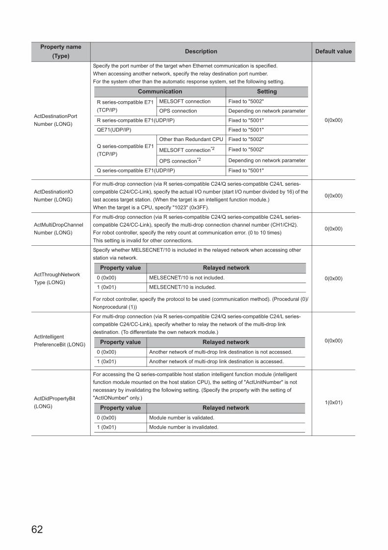
62
ActDestinationPort
Number (LONG)
Specify the port number of the target when Ethernet communication is specified.
When accessing another network, specify the relay destination port number.
For the system other than the automatic response system, set the following setting.
0(0x00)
ActDestinationIO
Number (LONG)
For multi-drop connection (via R series-compatible C24/Q series-compatible C24/L series-
compatible C24/CC-Link), specify the actual I/O number (start I/O number divided by 16) of the
last access target station. (When the target is an intelligent function module.)
When the target is a CPU, specify "1023" (0x3FF).
0(0x00)
ActMultiDropChannel
Number (LONG)
For multi-drop connection (via R series-compatible C24/Q series-compatible C24/L series-
compatible C24/CC-Link), specify the multi-drop connection channel number (CH1/CH2).
For robot controller, specify the retry count at communication error. (0 to 10 times)
This setting is invalid for other connections.
0(0x00)
ActThroughNetwork
Type (LONG)
Specify whether MELSECNET/10 is included in the relayed network when accessing other
station via network.
For robot controller, specify the protocol to be used (communication method). (Procedural (0)/
Nonprocedural (1))
0(0x00)
ActIntelligent
PreferenceBit (LONG)
For multi-drop connection (via R series-compatible C24/Q series-compatible C24/L series-
compatible C24/CC-Link), specify whether to relay the network of the multi-drop link
destination. (To differentiate the own network module.)
0(0x00)
ActDidPropertyBit
(LONG)
For accessing the Q series-compatible host station intelligent function module (intelligent
function module mounted on the host station CPU), the setting of "ActUnitNumber" is not
necessary by invalidating the following setting. (Specify the property with the setting of
"ActIONumber" only.)1(0x01)
Property name
(Type)Description Default value
Communication Setting
R series-compatible E71
(TCP/IP)
MELSOFT connection Fixed to "5002"
OPS connection Depending on network parameter
R series-compatible E71(UDP/IP) Fixed to "5001"
QE71(UDP/IP) Fixed to "5001"
Q series-compatible E71
(TCP/IP)
Other than Redundant CPU Fixed to "5002"
MELSOFT connection*2 Fixed to "5002"
OPS connection*2 Depending on network parameter
Q series-compatible E71(UDP/IP) Fixed to "5001"
Property value Relayed network
0 (0x00) MELSECNET/10 is not included.
1 (0x01) MELSECNET/10 is included.
Property value Relayed network
0 (0x00) Another network of multi-drop link destination is not accessed.
1 (0x01) Another network of multi-drop link destination is accessed.
Property value Relayed network
0 (0x00) Module number is validated.
1 (0x01) Module number is invalidated.
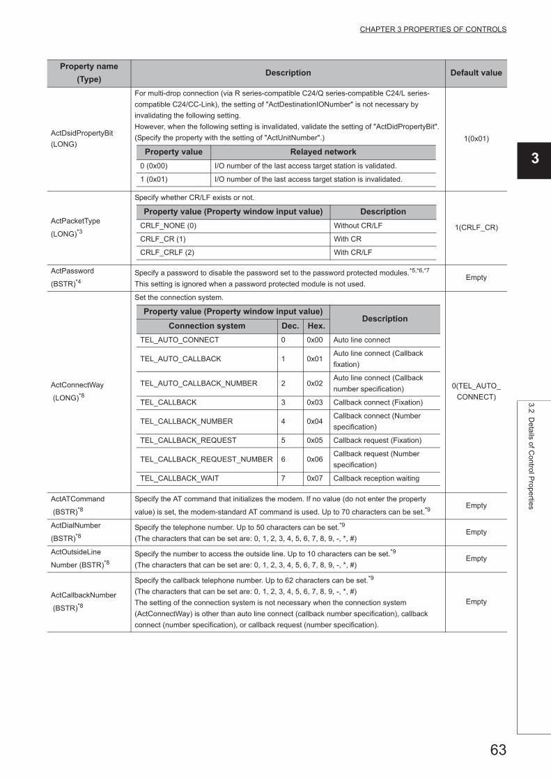
63
CHAPTER 3 PROPERTIES OF CONTROLS
3
3.2 Details of C
ontrol Properties
ActDsidPropertyBit
(LONG)
For multi-drop connection (via R series-compatible C24/Q series-compatible C24/L series-
compatible C24/CC-Link), the setting of "ActDestinationIONumber" is not necessary by
invalidating the following setting.
However, when the following setting is invalidated, validate the setting of "ActDidPropertyBit".
(Specify the property with the setting of "ActUnitNumber".) 1(0x01)
ActPacketType
(LONG)*3
Specify whether CR/LF exists or not.
1(CRLF_CR)
ActPassword
(BSTR)*4Specify a password to disable the password set to the password protected modules.*5,*6,*7
This setting is ignored when a password protected module is not used.Empty
ActConnectWay
(LONG)*8
Set the connection system.
0(TEL_AUTO_
CONNECT)
ActATCommand
(BSTR)*8Specify the AT command that initializes the modem. If no value (do not enter the property
value) is set, the modem-standard AT command is used. Up to 70 characters can be set.*9Empty
ActDialNumber
(BSTR)*8Specify the telephone number. Up to 50 characters can be set.*9
(The characters that can be set are: 0, 1, 2, 3, 4, 5, 6, 7, 8, 9, -, *, #)Empty
ActOutsideLine
Number (BSTR)*8Specify the number to access the outside line. Up to 10 characters can be set.*9
(The characters that can be set are: 0, 1, 2, 3, 4, 5, 6, 7, 8, 9, -, *, #)Empty
ActCallbackNumber
(BSTR)*8
Specify the callback telephone number. Up to 62 characters can be set.*9
(The characters that can be set are: 0, 1, 2, 3, 4, 5, 6, 7, 8, 9, -, *, #)
The setting of the connection system is not necessary when the connection system
(ActConnectWay) is other than auto line connect (callback number specification), callback
connect (number specification), or callback request (number specification).
Empty
Property name
(Type)Description Default value
Property value Relayed network
0 (0x00) I/O number of the last access target station is validated.
1 (0x01) I/O number of the last access target station is invalidated.
Property value (Property window input value) Description
CRLF_NONE (0) Without CR/LF
CRLF_CR (1) With CR
CRLF_CRLF (2) With CR/LF
Property value (Property window input value)Description
Connection system Dec. Hex.
TEL_AUTO_CONNECT 0 0x00 Auto line connect
TEL_AUTO_CALLBACK 1 0x01Auto line connect (Callback
fixation)
TEL_AUTO_CALLBACK_NUMBER 2 0x02Auto line connect (Callback
number specification)
TEL_CALLBACK 3 0x03 Callback connect (Fixation)
TEL_CALLBACK_NUMBER 4 0x04Callback connect (Number
specification)
TEL_CALLBACK_REQUEST 5 0x05 Callback request (Fixation)
TEL_CALLBACK_REQUEST_NUMBER 6 0x06Callback request (Number
specification)
TEL_CALLBACK_WAIT 7 0x07 Callback reception waiting

64
ActLineType (LONG)*8
Recognize the line type.
1(LINETYPE_
TONE)
ActConnectionCD
WaitTime (LONG)*8
Line connection CD signal confirmation time
Set the time for watching the ON/OFF of the CD signal line when the line is connected.
(Applicable setting range: 1 to 999, unit: seconds)
Increase the set time if the CD signal does not turn ON within the preset time depending on the
line-connected region (Example: overseas).
90
ActConnectionModem
ReportWaitTime
(LONG)*8
Line connection modem waiting time
Set the waiting time for a result code response from the modem after line connection.
(Applicable setting range: 1 to 999, unit: seconds)
Increase the set time if the response speed of the modem is slow.
5
ActDisconnectionCD
WaitTime (LONG)*8
Line disconnection CD signal confirmation time
Set the time for watching the ON/OFF of the CD signal line when the line is disconnected.
(Applicable setting range: 1 to 999, unit: seconds)
Increase the set time if the CD signal does not turn OFF within the preset time depending on
the line-connected region (Example: overseas).
5
ActDisconnectionDelay
Time (LONG)*8
Line disconnection delay timeSet the guard time (no communication time) of the escape command sent to the modem. (Applicable setting range: 1 to 999, unit: seconds)Increase the set time if the response speed of the modem is slow.
3
ActTransmissionDelay
Time (LONG)*8
Data send delay timeSet the time to be provided before the AT command is sent. (Applicable setting range: 0 to 999, unit: seconds)Increase the set time if the error code (0xF2100008) is returned though the correct AT command is set.Increase the set time if the response speed of the modem is slow.
0
ActATCommandResponseWaitTime
(LONG)*8
AT command send response waiting time (Applicable setting range: 1 to 999, unit: seconds)Increase the set time if the response speed of the modem is slow.
1
ActPasswordCancelResponseWaitTime
(LONG)*8
Password cancel response waiting time (Applicable setting range: 1 to 999, unit: seconds)Increase the set time if the quality of the line with the other end is low.
5
ActATCommandPasswordCancelRetry
Times (LONG)*8
AT command/password cancel send retry count(Applicable setting range: 1 to 999, unit: number of times)
3
Property name
(Type)Description Default value
Property value (Property window input value)Description
Line type Dec. Hex.
LINETYPE_PULSE 0 0x00 Pulse (Dial line)
LINETYPE_TONE 1 0x01 Tone (Push button line)
LINETYPE_ISDN 2 0x02 ISDN (ISDN line)

65
CHAPTER 3 PROPERTIES OF CONTROLS
3
3.2 Details of C
ontrol Properties
ActCallbackCancel
WaitTime (LONG)*8
Callback line disconnection waiting time (Applicable setting range: 1 to 180, unit: seconds)Increase the set time if the line at the other end (Q series-compatible C24) is not disconnected within the preset time depending on the line-connected region (Example: overseas).The setting is not necessary when the connection system (ActConnectWay) is other than callback connect or callback request.
90
ActCallbackDelayTime
(LONG)*8
Callback execution delay time (Applicable setting range: 1 to 999, unit: seconds)Increase the set time if the device for relaying connection to the line (Example: modem or like) requires the predetermined time for reconnection after line disconnection.The setting is not necessary when the connection system (ActConnectWay) is other than callback connect or callback request.
20
ActCallbackReceptionWaitingTimeOut
(LONG)*8
Callback receive waiting time-out period (Applicable setting range: 1 to 3600, unit: seconds)Set the waiting time for a telephone line connection request from Q series-compatible C24 in a callback receive waiting status.If the set time elapsed, the callback reception waiting status is exited, and since the connection of the telephone line was not completed, the Connect function is terminated abnormally.The setting is not necessary when the connection system (ActConnectWay) is other than callback reception waiting.
120
ActTargetSimulator(LONG)
Specify the connection destination GX Simulator2 in start status.When connecting to FXCPU, specify "0" (0x00).
0(0x00)
Specify the connection destination MT Simulator2 in start status..
Property name
(Type)Description Default value
Property value Description
0 (0x00)
None
(When only one simulator is in start status, connects to the simulator
in start status.
When multiple simulators are in start status, search for the
simulators in start status and connect them in alphabetical order.)
1 (0x01) Simulator A
2 (0x02) Simulator B
3 (0x03) Simulator C
4 (0x04) Simulator D
Property value Description
2 (0x02) Simulator No.2
3 (0x03) Simulator No.3
4 (0x04) Simulator No.4

66
ActUnitType (LONG)
Specify the module type connected to the physical port.
0x13
(UNIT_QNCPU)
Property name
(Type)Description Default value
Module type Connection system Value
UNIT_RJ71C24
R series-compatible C24 module direct
connection0x1000
R series-compatible C24 connection via
GOT2000/1000 series
UNIT_QJ71C24
Q series-compatible C24 module direct
connection
0x19Q series-compatible C24/CMO connection via
modem
Q series-compatible C24 connection via
GOT2000/1000 series
UNIT_LJ71C24
L series-compatible C24 module direct
connection
0x54L series-compatible C24 connection via modem
L series-compatible C24 connection via
GOT2000/1000 series
UNIT_FX485BD FX extended port (RS-485) direct connection 0x24
UNIT_RJ71EN71Via R series-compatible E71 connection (IP
specification)0x1001
UNIT_RJ71EN71_DIRECTVia R series-compatible E71 connection (Direct
connection)0x1005
UNIT_QJ71E71
Q series-compatible E71 Ethernet port
connection
/direct connection
0x1A
UNIT_RETHER RCPU Ethernet port connection (IP specification) 0x1002
UNIT_RETHER_DIRECT RCPU Ethernet port direct connection 0x1003
UNIT_FXVETHER FX5CPU Ethernet port connection 0x2001
UNIT_FXVETHER_DIRECT FX5CPU Ethernet port direct connection 0x2002
UNIT_LNETHER LCPU Ethernet port connection 0x52
UNIT_LNETHER_DIRECT LCPU Ethernet port direct connection 0x53
UNIT_QNETHER QCPU Ethernet port connection 0x2C
UNIT_QNETHER_DIRECT QCPU Ethernet port direct connection 0x2D
UNIT_NZ2GF_ETBEthernet adapter module (NZ2GF-ETB)
connection0x59
UNIT_NZ2GF_ETB_DIRECTEthernet adapter module (NZ2GF-ETB) direct
connection0x5A
UNIT_FXETHERFXCPU Ethernet adapter (FX3U-ENET-ADP)
via hub0x4A
UNIT_FXETHER_DIRECTFXCPU Ethernet adapter (FX3U-ENET-ADP)
direct connection0x4B
UNIT_FXVCPU FX5CPU Serial port connection 0x2000
UNIT_QNCPU
QCPU (Q mode) RS232C port direct connection
0x13GOT2000/1000 series QCPU (Q mode) direct
connection
UNIT_LNCPULCPU RS232C port direct connection
0x50GOT2000/1000 series LCPU direct connection
UNIT_QNMOTION Q motion CPU-RS232C port direct connection 0x1C

67
CHAPTER 3 PROPERTIES OF CONTROLS
3
3.2 Details of C
ontrol Properties
ActUnitType (LONG)
Specify the module type connected to the physical port.
0x13
(UNIT_QNCPU)
Property name
(Type)Description Default value
Module type Connection system Value
UNIT_FXCPU
FXCPU-RS422 port direct connection
0x0FFXCPU direct connection via modem
FXCPU USB direct connection
GOT2000/1000 series FXCPU direct connection
UNIT_RUSB RCPU USB port direct connection 0x1004
UNIT_QNUSB QCPU (Q mode) USB port direct connection 0x16
UNIT_LNUSB LCPU USB port direct connection 0x51
UNIT_QSUSBQSCPU (Safety programmable controller) USB
port connection0x29
UNIT_QNMOTIONUSB Q motion CPU USB port direct connection 0x1D
UNIT_MNETHBOARD MELSECNET/H board connection 0x1E
UNIT_MNETGBOARD CC-Link IE Controller Network board connection 0x2B
UNIT_CCIEFBOARD CC-Link IE Field Network board connection 0x2F
UNIT_CCLINKBOARD CC-Link board connection 0x0C
UNIT_G4QNCPUQ series-compatible AJ65BT-G4-S3 module
direct connection0x1B
UNIT_SIMULATOR Simulator (GX Simulator) connection 0x0B
UNIT_SIMULATOR2*10Simulator (GX Simulator 2) connection
0x30Simulator (MT Simulator 2) connection
UNIT_A900GOT GOT2000/1000/900 series connection 0x21
UNIT_GOT_RJ71EN71R series-compatible E71 connection via
GOT2000/1000 series 0x1051
UNIT_GOT_QJ71E71Q series-compatible E71 connection via
GOT2000/1000 series0x40
UNIT_GOT_RETHERRCPU Ethernet port connection via GOT2000/
1000 series 0x1052
UNIT_GOT_QNETHERQCPU Ethernet port connection via GOT2000/
1000 series0x41
UNIT_GOT_LNETHERLCPU Ethernet port connection via GOT2000/
1000 series0x55
UNIT_GOT_NZ2GF_ETBEthernet adapter module (NZ2GF-ETB)
connection via GOT2000/1000 series0x5B
UNIT_GOT_FXETHERFXCPU Ethernet adapter (FX3U-ENET-ADP)
connection via GOT2000/1000 series0x61
UNIT_GOT_FXENETFXCPU Ethernet module (FX3U-ENET(-L))
connection via GOT2000/1000 series0x62
UNIT_GOTETHER_RJ71C24RCPU Ethernet port (RS422) connection via
GOT2000/1000 series 0x1061
UNIT_GOTETHER_QNCPUQCPU (Q mode) Ethernet port (RS422)
connection via GOT2000/1000 series0x56
UNIT_GOTETHER_LNCPULCPU Ethernet port (RS232C) connection via
GOT2000/1000 series0x57
UNIT_GOTETHER_FXCPUFXCPU Ethernet port connection via GOT2000/
1000 series0x60
UNIT_GOTETHER_QBUSQ series bus Ethernet port connection via
GOT2000/1000 series0x58
UNIT_QBF Bus connection 0x1F

68
ActProtocolType
(LONG)
Specify the communication protocol type of the module (board) to be connected.
0x04
(PROTOCOL_
SERIAL)
*1 : Except for CPU boards and AF boards.*2 : For details, refer to the following manual.
Q Corresponding Ethernet Interface Module User's Manual (Basic)*3 : This property can be used for inverter communication.*4 : This property can be used for Ethernet communication.*5 : The setting of ActPassword is not necessary if a password is not set.*6 : Characters exceeded the maximum number of characters for the password are ignored.*7 : If a character other than alphanumeric is specified, a character code conversion error (0xF1000001) occurs at the execution of the
Open function.*8 : This property can be used for modem communication. It cannot be used for ActMLProgType control.*9 : If the characters entered exceed the limit of set characters, the characters outside the setting range are ignored.*10 : When the CPU type is Q motion CPU, connected to MT Simulator2. Other than that, connected to GX Simulator2.*11 : The communication protocol type can be used when ActMxUnitSeries is 1 (0x01).
Property name
(Type)Description Default value
Communication protocol
typeConnection system Value
PROTOCOL_SERIAL Via serial port 0x04 (4)
PROTOCOL_USB Via USB port 0x0D (13)
PROTOCOL_TCPIP Via TCP/IP 0x05 (5)
PROTOCOL_UDPIP Via UDP/IP 0x08 (8)
PROTOCOL_MNETH Via MELSECNET/H board 0x0F (15)
PROTOCOL_MNETG Via CC-Link IE Controller Network board 0x14 (20)
PROTOCOL_CCIEF Via CC-Link IE Field Network board 0x15 (21)
PROTOCOL_CCLINK Via CC-Link 0x07 (7)
PROTOCOL_SERIALMODEM Via serial port and modem 0x0E (14)
PROTOCOL_TEL Via TEL 0x0A (10)
PROTOCOL_QBF Via Q series bus 0x10 (16)
PROTOCOL_USBGOT Via USB port and GOT 0x13 (19)
PROTOCOL_SHAREDMEMORY Via shared memory server (Simulator) 0x06 (6)
COMM_RS232C*11 Inverter RS232C communication 0x00 (0)
COMM_USB*11 Inverter USB port communication 0x01 (1)
RC_PROTOCOL_SERIAL Robot controller COM communication 0x01 (1)
RC_PROTOCOL_USB Robot controller USB communication 0x04 (4)
RC_PROTOCOL_TCPIPRobot controller Ethernet
communication0x02 (2)

69
CHAPTER 4 PROPERTY SETTINGS OF COMMUNICATION PATHS
4
4.1 Descriptions o
f Property S
etting
CHAPTER 4 PROPERTY SETTINGS OF
COMMUNICATION PATHS
This chapter explains the details of accessible communication paths and property settings.
4.1 Descriptions of Property Setting
The following is the descriptions of how communication paths and properties of control are explained in this chapter.
The indicated default values are the property values displayed on the property window of Visual Basic® .NET, Visual C++®
.NET, or Visual C#® .NET.For the default values required to be entered in values other than the decimal number to change the property values in a program are described in the parentheses.
(1) Configuration
A diagram of system configuration
(2) Property pattern
Indicates the accessible ranges of the
used control and the patterns of the properties.
(3) Property list
(a) Property
Describes the property name.
(b) Default value
Describes the default value of the property.
The default value used for changing the property in the program are shown in the parentheses.
(c) Property pattern
Describes the property settings necessary to set the communication settings.
The property pattern numbers correspond to the numbers in the table of "Property pattern".

70
4.2 Serial Communication
4.2.1 Serial communication when the connected station is R series-compatible C24
(1) When a relayed module other than the connected station side R series-
compatible C24 exists
(a) Configuration
(b) Property patterns
*1 : Only CPU No.2 or later in a multiple CPU configuration can be accessed.*2 : Since CC-Link IE Controller Network is not supported, RCPU relayed by CC-Link IE Controller Network cannot be
accessed.
Connected station
CPURelayed network
Relayed station CPU
RCPUR motion
CPURCPU
R motion
CPU
*1
CC IE Control
CC IE Field*2
MELSECNET/H
Ethernet
Serial communication
CC-Link
Connected station
CPU
Relayed network
Relayed station CPU
RCPUR motion
CPU
QCPU
(Q mode)
C
Controller
module
LCPU QSCPUQ motion
CPUFXCPU
*1
CC IE Control
CC IE Field
MELSECNET/H
Ethernet
Serial communication
CC-Link
: Accessible (The number in the circle is the property pattern number.), : Inaccessible
Personal computer
Connected
station CPU
R series-
compatible C24
Relayed
module
Relayed network
Relayed
station CPU
Relayed
module

71
CHAPTER 4 PROPERTY SETTINGS OF COMMUNICATION PATHS
4
4.2 Serial C
omm
unicatio
n4.2.1 S
erial com
munication w
hen the connected statio
n is R series-com
patible C24
(c) Property list
The following table shows the property settings of communication paths. The setting is not necessary for those
properties without description.
Property Default valueProperty pattern
*1
ActBaudRate
19200
(BAUDRATE_
19200)
Match to the setting of R series-compatible C24.
ActConnectUnit
Number0 (0x00) Connected station side module station number
ActControl
8
(TRC_DTR_OR_
RTS)
Depending on the used cable.
ActCpuType34
(CPU_Q02CPU)CPU type corresponding to the target station
ActDestination
IONumber *20 (0x00) Fixed to 0 (0x00) Fixed to 0 (0x00)
Target station side
For single CPU
Fixed to 1023 (0x3FF)
For multiple CPUs
Connected CPU:
1023 (0x3FF)
No. 1: 992 (0x3E0)
No. 2: 993 (0x3E1)
No. 3: 994 (0x3E2)
No. 4: 995 (0x3E3)
For Redundant CPU
Control system:
976 (0x3D0)
No specification:
1023 (0x3FF)
Target station side
For single CPU
Fixed to 1023 (0x3FF)
For multiple CPUs
Connected CPU:
1023 (0x3FF)
No. 1: 992 (0x3E0)
No. 2: 993 (0x3E1)
No. 3: 994 (0x3E2)
No. 4: 995 (0x3E3)
For Redundant CPU
Control system:
976 (0x3D0)
No specification:
1023 (0x3FF)
ActDidProperty
Bit1 (0x01) Fixed to 1 (0x01) Fixed to 1 (0x01) Fixed to 0 (0x00) Fixed to 0 (0x00)
ActDsidProperty
Bit1 (0x01) Fixed to 1 (0x01) Fixed to 1 (0x01) Fixed to 0 (0x00) Fixed to 0 (0x00)
ActIntelligent
PreferenceBit0 (0x00) Fixed to 0 (0x00)
ActIONumber *2 1023 (0x3FF)
For single CPU
Fixed to 1023 (0x3FF)
For multiple CPUs
Connected CPU:
1023 (0x3FF)
No. 1: 992 (0x3E0)
No. 2: 993 (0x3E1)
No. 3: 994 (0x3E2)
No. 4: 995 (0x3E3)
For single CPU
Fixed to 1023 (0x3FF)
For multiple CPUs
Connected CPU:
1023 (0x3FF)
No. 1: 992 (0x3E0)
No. 2: 993 (0x3E1)
No. 3: 994 (0x3E2)
No. 4: 995 (0x3E3)
Connected station side
module I/O address
Connected station side
module I/O address
ActMultiDrop
ChannelNumber *30 (0x00) Fixed to 0 (0x00) Fixed to 0 (0x00)
Multi-drop channel
numberFixed to 0 (0x00)
ActNetwork
Number0 (0x00) Fixed to 0 (0x00)
Target station side
module network
number
Fixed to 0 (0x00) Fixed to 0 (0x00)
ActParity1
(ODD_PARITY)Fixed to 1(ODD_PARITY)
ActPortNumber 1 (PORT_1) Personal computer side COM port number

72
*1 : Note the following considerations when accessing via Ethernet module (R series-compatible E71). • For ActNetworkNumber and ActStationNumber, specify the value set in the parameter setting of the target station side R series-
compatible E71. • Set "Station No. IP information" in the parameter setting of R series-compatible E71. When setting the parameter, specify the
setting other than the automatic response system (any of the IP address calculation system, table conversion system, and combined system) for "Station No. IP information system".
*2 : For the I/O address, specify the value of the actual start I/O number divided by 16.*3 : Specify the following value for the channel number to be multi-drop linked.
0: Default channel of module1: Channel 12: Channel 2
ActProtocolType
0x04
(PROTOCOL_
SERIAL)
PROTOCOL_SERIAL
ActPacketType0x01
(PACKET_PLC1)PACKET_PLC1
ActHostAddress 1.1.1.1 Fixed to NULL
ActCpuTimeOut 0(0x00) Fixed to 0 (0x00)
ActDataBits 8(DATABIT_8) Fixed to 8 (0x08)
ActStopBits0(STOPBIT_
ONE)Fixed to 0 (0x00)
ActSumCheck0(NO_SUM_
CHECK)Fixed to 0 (0x00)
ActSource
NetworkNumber0(0x00) Fixed to 0 (0x00)
ActSourceStation
Number0(0x00) Fixed to 0 (0x00)
ActDestination
PortNumber0(0x00) Fixed to 0 (0x00)
ActStation
Number255 (0xFF) Fixed to 255 (0xFF)
Target station side
module station numberFixed to 255 (0xFF) Fixed to 255 (0xFF)
ActThrough
NetworkType0 (0x00)
MELSECNET/10 is not included. : 0 (0x00)
MELSECNET/10 is included. : 1 (0x01)
ActTimeOut 10000 Any value specified by user in ms units
ActUnitNumber 0 (0x00) Fixed to 0 (0x00) Fixed to 0 (0x00)Target station side
module station number
Target station side
module station number
ActUnitType0x13
(UNIT_QNCPU)UNIT_RJ71C24
Property Default valueProperty pattern
*1

73
CHAPTER 4 PROPERTY SETTINGS OF COMMUNICATION PATHS
4
4.2 Serial C
omm
unicatio
n4.2.1 S
erial com
munication w
hen the connected statio
n is R series-com
patible C24
(2) When performing multi-drop link on the connected station side R series-
compatible C24 with the relayed module
(a) Configuration
(b) Property patterns
*1 : For the Independent mode, set the following parameters. • CH1 side: Operation setting of Transmission setting = Independent (0), Communication protocol setting = 0 • CH2 side: Operation setting of Transmission setting = Independent (0)
*2 : For the Synchronous mode, set the following parameters. • CH1 side: Operation setting of Transmission setting = Independent (0), Communication protocol setting = 8 • CH2 side: Operation setting of Transmission setting = Synchronous (1), Communication protocol setting = 0
Connected
station CPURelayed network
Relayed station CPU
RCPU RCPUR motion
CPU
Independent
mode *1
Serial
communication
Synchronous
mode *2
Connected
station CPU
Relayed network
Relayed station CPU
RCPUQCPU
(Q mode)
C
Controller
module
LCPU QSCPUQ motion
CPUFXCPU
Independent
mode *1
Serial
communication
Synchronous
mode *2
: Accessible (The number in the circle is the property pattern number.), : Inaccessible
Personal computer Relayed network
Relayed
station CPU
Relayed
module
Connected
station CPU
R series-compatible
C24
Multi-drop link

74
(c) Property list
The following table shows the property settings of communication paths. The setting is not necessary for those
properties without description.
Property Default valueProperty pattern
ActBaudRate
19200
(BAUDRATE_
19200)
Match to the setting of R series-compatible C24.
ActConnectUnit
Number0 (0x00) Connected station side module station number
Target station side
module station number
ActControl
8
(TRC_DTR_OR_
RTS)
Depending on the used cable.
ActCpuType34
(CPU_Q02CPU)CPU type corresponding to the target station
ActDestination
IONumber *10 (0x00) Fixed to 0 (0x00)
Target station side
For single CPU
Fixed to 1023 (0x3FF)
For multiple CPUs
Connected CPU:
1023 (0x3FF)
No. 1: 992 (0x3E0)
No. 2: 993 (0x3E1)
No. 3: 994 (0x3E2)
No. 4: 995 (0x3E3)
Fixed to 0 (0x00)
ActDidProperty
Bit1 (0x01) Fixed to 1 (0x01) Fixed to 1 (0x01) Fixed to 1 (0x01)
ActDsidProperty
Bit1 (0x01) Fixed to 1 (0x01) Fixed to 1 (0x01) Fixed to 1 (0x01)
ActIntelligent
PreferenceBit0 (0x00) Fixed to 0 (0x00)
ActIONumber *1 1023 (0x3FF)
For single CPU
Fixed to 1023 (0x3FF)
For multiple CPUs
Connected CPU:
1023 (0x3FF)
No. 1: 992 (0x3E0)
No. 2: 993 (0x3E1)
No. 3: 994 (0x3E2)
No. 4: 995 (0x3E3)
Connected station side
module I/O address
Target station side
For single CPU
Fixed to 1023 (0x3FF)
For multiple CPUs
Connected CPU:
1023 (0x3FF)
No. 1: 992 (0x3E0)
No. 2: 993 (0x3E1)
No. 3: 994 (0x3E2)
No. 4: 995 (0x3E3)
ActMultiDrop
ChannelNumber *20 (0x00) Fixed to 0 (0x00)
Multi-drop channel
numberFixed to 0 (0x00)
ActNetwork
Number0 (0x00) Fixed to 0 (0x00)
ActParity1
(ODD_PARITY)Fixed to 1(ODD_PARITY)
ActPortNumber 1 (PORT_1) Personal computer side COM port number
ActProtocolType
0x04
(PROTOCOL_
SERIAL)
PROTOCOL_SERIAL
ActPacketType0x01
(PACKET_PLC1)PACKET_PLC1

75
CHAPTER 4 PROPERTY SETTINGS OF COMMUNICATION PATHS
4
4.2 Serial C
omm
unicatio
n4.2.1 S
erial com
munication w
hen the connected statio
n is R series-com
patible C24
*1 : For the I/O address, specify the value of the actual start I/O number divided by 16.*2 : Specify the following value for the channel number to be multi-drop linked.
0: Default channel of module1: Channel 12: Channel 2
When the connected station side R series-compatible C24 is set to the synchronous mode, always validate (ON) "sum check (SW06)" for the transmission specification software switch setting of the R series-compatible C24 parameter.If it is invalidated (OFF), a communication error occurs and the communication is disabled.
ActHostAddress 1.1.1.1 Fixed to NULL
ActCpuTimeOut 0(0x00) Fixed to 0 (0x00)
ActDataBits 8(DATABIT_8) Fixed to 8 (0x08)
ActStopBits0(STOPBIT_
ONE)Fixed to 0 (0x00)
ActSumCheck0(NO_SUM_
CHECK)Fixed to 0 (0x00)
ActSource
NetworkNumber0(0x00) Fixed to 0 (0x00)
ActSourceStation
Number0(0x00) Fixed to 0 (0x00)
ActDestination
PortNumber0(0x00) Fixed to 0 (0x00)
ActStation
Number255 (0xFF) Fixed to 255 (0xFF)
ActThrough
NetworkType0 (0x00)
MELSECNET/10 is not included. : 0 (0x00)
MELSECNET/10 is included. : 1 (0x01)
ActTimeOut 10000 Any value specified by user in ms units
ActUnitNumber 0 (0x00) Fixed to 0 (0x00)Target station side
module station numberFixed to 0 (0x00)
ActUnitType0x13
(UNIT_QNCPU)UNIT_RJ71C24
Property Default valueProperty pattern

76
4.2.2 Serial communication when the connected station is Q series-compatible C24
(1) When a relayed module other than the connected station side Q series-
compatible C24 exists
(a) Configuration
(b) Property patterns
*1 : Relayed stations cannot be accessed via Q motion CPU.*2 : Since CC-Link IE Field Network is not supported, R motion CPU, Q12DCCPU-V (Basic mode), QSCPU, and Q motion
CPU relayed by CC-Link IE Field Network cannot be accessed.*3 : Since CC-Link IE Controller Network is not supported, LCPU relayed by CC-Link IE Controller Network cannot be
accessed.*4 : For Redundant CPU, serial communication modules on the main base cannot be accessed.*5 : Supported by FX3G(C)CPU and FX3U(C)CPU within the own network only.*6 : Only CPU No.2 or later in a multiple CPU configuration can be accessed.
Connected station CPU
Relayed network
Relayed station CPU
QCPU
(Q mode)
C
Controller
module
Q motion
CPURCPU
R motion
CPU
*6 *1
CC IE Control
CC IE Field
MELSECNET/H
Ethernet
Serial
communication
CC-Link
Connected station CPU
Relayed network
Relayed station CPU
QCPU
(Q mode)
C
Controller
module
Q motion
CPU
QCPU
(Q mode)
C
Controller
module
LCPU QSCPU
Q
motion
CPU
FXCPU
*6 *1
CC IE Control
CC IE Field *2 *3 *2 *2
MELSECNET/H
Ethernet
Serial
communication*4
CC-Link *5
: Accessible (The number in the circle is the property pattern number.), : Inaccessible
Personal computer Relayed network
Relayed
station CPU
Connected
station CPU
Q series-compatible
C24
Relayed
module
Relayed
module

77
CHAPTER 4 PROPERTY SETTINGS OF COMMUNICATION PATHS
4
4.2 Serial C
omm
unicatio
n4.2.2 S
erial com
munication w
hen the connected statio
n is Q series-com
patible C24
(c) Property list
The following table shows the property settings of communication paths. The setting is not necessary for those
properties without description.
Property Default valueProperty pattern
*1
ActBaudRate
19200
(BAUDRATE_
19200)
Match to the setting of Q series-compatible C24.
ActConnectUnit
Number0 (0x00) Connected station side module station number
ActControl
8
(TRC_DTR_OR_
RTS)
Depending on the used cable.
ActCpuType34
(CPU_Q02CPU)CPU type corresponding to the target station
ActDestination
IONumber0 (0x00) Fixed to 0 (0x00) Fixed to 0 (0x00)
Target station side
For single CPU
Fixed to 1023 (0x3FF)
For multiple CPUs
Connected CPU:
1023 (0x3FF)
No. 1: 992 (0x3E0)
No. 2: 993 (0x3E1)
No. 3: 994 (0x3E2)
No. 4: 995 (0x3E3)
For Redundant CPU
Control system:
976 (0x3D0)
No specification:
1023 (0x3FF)
Target station side
For single CPU
Fixed to 1023 (0x3FF)
For multiple CPUs
Connected CPU:
1023 (0x3FF)
No. 1: 992 (0x3E0)
No. 2: 993 (0x3E1)
No. 3: 994 (0x3E2)
No. 4: 995 (0x3E3)
For Redundant CPU
Control system:
976 (0x3D0)
No specification:
1023 (0x3FF)
ActDidProperty
Bit1 (0x01) Fixed to 1 (0x01) Fixed to 1 (0x01) Fixed to 0 (0x00) Fixed to 0 (0x00)
ActDsidProperty
Bit1 (0x01) Fixed to 1 (0x01) Fixed to 1 (0x01) Fixed to 0 (0x00) Fixed to 0 (0x00)
ActHostAddress 1.1.1.1 Fixed to NULL
ActIntelligent
PreferenceBit0 (0x00) Fixed to 0 (0x00)
ActIONumber*2 1023 (0x3FF)
Target station side
For single CPU
Fixed to 1023 (0x3FF)
For multiple CPUs
Connected CPU:
1023 (0x3FF)
No. 1: 992 (0x3E0)
No. 2: 993 (0x3E1)
No. 3: 994 (0x3E2)
No. 4: 995 (0x3E3)
For Redundant CPU
Control system:
976 (0x3D0)
No specification:
1023 (0x3FF)
Target station side
For single CPU
Fixed to 1023 (0x3FF)
For multiple CPUs
Connected CPU:
1023 (0x3FF)
No. 1: 992 (0x3E0)
No. 2: 993 (0x3E1)
No. 3: 994 (0x3E2)
No. 4: 995 (0x3E3)
For Redundant CPU
Control system:
976 (0x3D0)
No specification:
1023 (0x3FF)
Connected station side
module I/O address
Connected station side
module I/O address
ActMultiDrop
ChannelNumber*30 (0x00) Fixed to 0 (0x00) Fixed to 0 (0x00)
Multi-drop channel
numberFixed to 0 (0x00)

78
*1 : Note the following considerations when accessing via Ethernet module (Q series-compatible E71). • For ActNetworkNumber and ActStationNumber, specify the value set in the parameter setting of the target station side Q series-
compatible E71. • Set "Station No. IP information" in the parameter setting of Q series-compatible E71. When setting the parameter, specify the
setting other than the automatic response system (any of the IP address calculation system, table conversion system, and combined system) for "Station No. IP information system".
*2 : For the I/O address, specify the value of the actual start I/O number divided by 16.*3 : Specify the following value for the channel number to be multi-drop linked.
0: Default channel of module1: Channel 12: Channel 2
ActNetwork
Number0 (0x00) Fixed to 0 (0x00)
Target station side
module network
number
Fixed to 0 (0x00) Fixed to 0 (0x00)
ActParity1
(ODD_PARITY)Match to the setting of Q series-compatible C24.
ActPortNumber 1 (PORT_1) Personal computer side COM port number
ActProtocolType
0x04
(PROTOCOL_
SERIAL)
PROTOCOL_SERIAL (0x04)
ActStation
Number255 (0xFF) Fixed to 255 (0xFF)
Target station side
module station numberFixed to 255 (0xFF) Fixed to 255 (0xFF)
ActThrough
NetworkType0 (0x00)
MELSECNET/10 is not included. : 0 (0x00)
MELSECNET/10 is included. : 1 (0x01)
ActTimeOut 10000 Any value specified by user in ms units
ActUnitNumber 0 (0x00) Fixed to 0 (0x00) Fixed to 0 (0x00)Target station side
module station number
Target station side
module station number
ActUnitType0x13
(UNIT_QNCPU)UNIT_QJ71C24 (0x19)
Property Default valueProperty pattern
*1

79
CHAPTER 4 PROPERTY SETTINGS OF COMMUNICATION PATHS
4
4.2 Serial C
omm
unicatio
n4.2.2 S
erial com
munication w
hen the connected statio
n is Q series-com
patible C24
(2) When performing multi-drop link on the connected station side Q series-
compatible C24 with the relayed module
(a) Configuration
(b) Property patterns
*1 : Indicates the CH2 side setting. (The CH1 side is fixed to the independent mode.)*2 : For Redundant CPU, serial communication modules on the main base cannot be accessed.*3 : Only CPU No.2 or later in a multiple CPU configuration can be accessed.
Connected
station CPU
Relayed network
Relayed station CPU
QCPU
(Q mode),
C Controller
module*3
RCPUR motion
CPU
Independent
mode*1
Serial
communication
Synchronous
mode*1
Connected
station CPU
Relayed network
Relayed station CPU
QCPU
(Q mode),
C Controller
module*3
QCPU
(Q mode)
C
Controller
module
LCPU QSCPUQ motion
CPUFXCPU
Independent
mode*1
Serial
communication
*2
Synchronous
mode*1 *2
: Accessible (The number in the circle is the property pattern number.), : Inaccessible
Personal computer Relayed network
Relayed
station CPU
Relayed
module
Connected
station CPU
Q series-compatible
C24
Multi-drop link

80
(c) Property list
The following table shows the property settings of communication paths. The setting is not necessary for those
properties without description.
Property Default valueProperty pattern
ActBaudRate19200
(BAUDRATE_19200)Match to the setting of Q series-compatible C24.
ActConnectUnitNumber 0 (0x00) Connected station side module station number
ActControl8
(TRC_DTR_OR_RTS)Depending on the used cable.
ActCpuType 34 (CPU_Q02CPU) CPU type corresponding to the target station
ActDestinationIONumber 0 (0x00) Fixed to 0 (0x00)
Target station side
For single CPU
Fixed to 1023 (0x3FF)
For multiple CPUs
Connected CPU:
1023 (0x3FF)
No. 1: 992 (0x3E0)
No. 2: 993 (0x3E1)
No. 3: 994 (0x3E2)
No. 4: 995 (0x3E3)
For Redundant CPU
Control system:
976 (0x3D0)
No specification:
1023 (0x3FF)
Fixed to 0 (0x00)
ActDidPropertyBit 1 (0x01) Fixed to 1 (0x01) Fixed to 0 (0x00) Fixed to 1 (0x01)
ActDsidPropertyBit 1 (0x01) Fixed to 1 (0x01) Fixed to 0 (0x00) Fixed to 1 (0x01)
ActIntelligentPreferenceBit 0 (0x00) Fixed to 0 (0x00)
ActIONumber*1 1023 (0x3FF)
Target station side
For single CPU
Fixed to 1023 (0x3FF)
For multiple CPUs
Connected CPU:
1023 (0x3FF)
No. 1: 992 (0x3E0)
No. 2: 993 (0x3E1)
No. 3: 994 (0x3E2)
No. 4: 995 (0x3E3)
For Redundant CPU
Control system:
976 (0x3D0)
No specification:
1023 (0x3FF)
Connected station side
module I/O address
Target station side
For single CPU
Fixed to 1023 (0x3FF)
For multiple CPUs
Connected CPU:
1023 (0x3FF)
No. 1: 992 (0x3E0)
No. 2: 993 (0x3E1)
No. 3: 994 (0x3E2)
No. 4: 995 (0x3E3)
For Redundant CPU
Control system:
976 (0x3D0)
No specification:
1023 (0x3FF)
ActMultiDropChannelNumber*2 0 (0x00) Fixed to 0 (0x00)Multi-drop channel
numberFixed to 0 (0x00)
ActNetworkNumber 0 (0x00) Fixed to 0 (0x00)
ActParity 1 (ODD_PARITY) Match to the setting of Q series-compatible C24.
ActPortNumber 1 (PORT_1) Personal computer side COM port number
ActProtocolType0x04
(PROTOCOL_SERIAL)PROTOCOL_SERIAL (0x04)
ActStationNumber 255 (0xFF) Fixed to 255 (0xFF)
ActThroughNetworkType 0 (0x00)MELSECNET/10 is not included. : 0 (0x00)
MELSECNET/10 is included. : 1 (0x01)
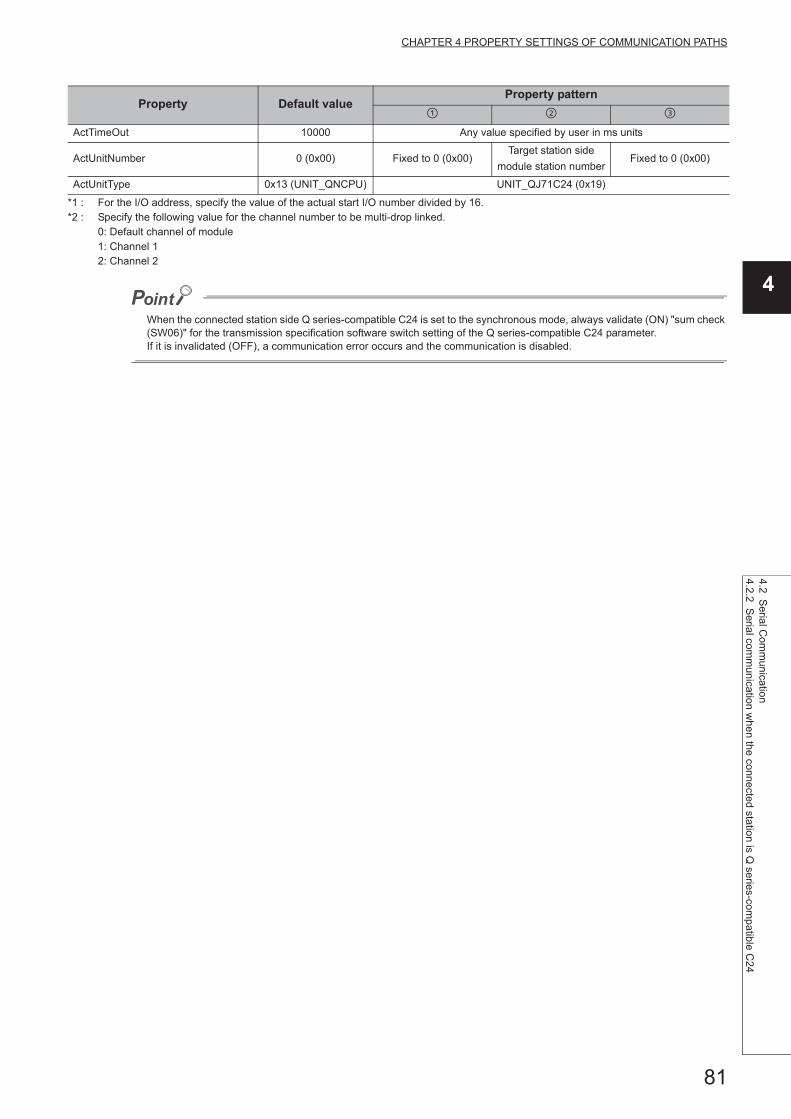
81
CHAPTER 4 PROPERTY SETTINGS OF COMMUNICATION PATHS
4
4.2 Serial C
omm
unicatio
n4.2.2 S
erial com
munication w
hen the connected statio
n is Q series-com
patible C24
*1 : For the I/O address, specify the value of the actual start I/O number divided by 16.*2 : Specify the following value for the channel number to be multi-drop linked.
0: Default channel of module1: Channel 12: Channel 2
When the connected station side Q series-compatible C24 is set to the synchronous mode, always validate (ON) "sum check (SW06)" for the transmission specification software switch setting of the Q series-compatible C24 parameter.If it is invalidated (OFF), a communication error occurs and the communication is disabled.
ActTimeOut 10000 Any value specified by user in ms units
ActUnitNumber 0 (0x00) Fixed to 0 (0x00)Target station side
module station numberFixed to 0 (0x00)
ActUnitType 0x13 (UNIT_QNCPU) UNIT_QJ71C24 (0x19)
Property Default valueProperty pattern

82
4.2.3 Serial communication when the connected station is L series-compatible C24
(1) When a relayed module other than the connected station side LJ71C24 exists
(a) Configuration
(b) Property patterns
*1 : Since CC-Link IE Controller Network is not supported, LCPU relayed by CC-Link IE Controller Network cannot be accessed.
*2 : Since CC-Link IE Field Network is not supported, Q12DCCPU-V (Basic mode) relayed by CC-Link IE Field Network cannot be accessed.
*3 : For Redundant CPU, serial communication modules on the main base cannot be accessed.
Connected
station CPURelayed network
Relayed station CPU
LCPU RCPUR motion
CPU
CC IE Field *1
MELSECNET/H
Ethernet
Serial communication
CC-Link
Connected
station CPU
Relayed network
Relayed station CPU
LCPUQCPU
(Q mode)
C
Controller
module
LCPU QSCPUQ motion
CPUFXCPU
CC IE Field *1 *2
MELSECNET/H
Ethernet
Serial communication *3
CC-Link
: Accessible (The number in the circle is the property pattern number.), : Inaccessible
Personal computer Relayed network
Relayed
station CPU
Connected
station CPU
L series-compatible
C24
Relayed
module
Relayed
module
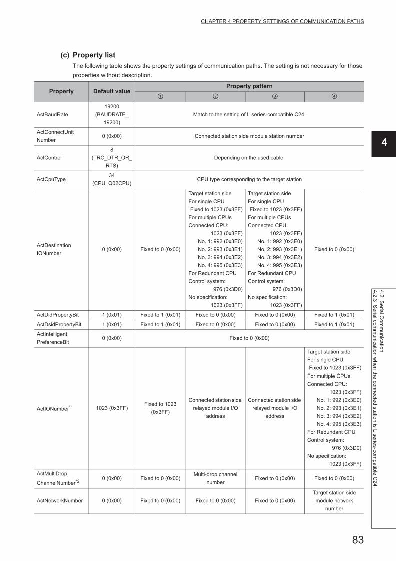
83
CHAPTER 4 PROPERTY SETTINGS OF COMMUNICATION PATHS
4
4.2 Serial C
omm
unicatio
n4.2.3 S
erial com
munication w
hen the connected statio
n is L series-compatib
le C2
4
(c) Property list
The following table shows the property settings of communication paths. The setting is not necessary for those
properties without description.
Property Default valueProperty pattern
ActBaudRate
19200
(BAUDRATE_
19200)
Match to the setting of L series-compatible C24.
ActConnectUnit
Number0 (0x00) Connected station side module station number
ActControl
8
(TRC_DTR_OR_
RTS)
Depending on the used cable.
ActCpuType34
(CPU_Q02CPU)CPU type corresponding to the target station
ActDestination
IONumber0 (0x00) Fixed to 0 (0x00)
Target station side
For single CPU
Fixed to 1023 (0x3FF)
For multiple CPUs
Connected CPU:
1023 (0x3FF)
No. 1: 992 (0x3E0)
No. 2: 993 (0x3E1)
No. 3: 994 (0x3E2)
No. 4: 995 (0x3E3)
For Redundant CPU
Control system:
976 (0x3D0)
No specification:
1023 (0x3FF)
Target station side
For single CPU
Fixed to 1023 (0x3FF)
For multiple CPUs
Connected CPU:
1023 (0x3FF)
No. 1: 992 (0x3E0)
No. 2: 993 (0x3E1)
No. 3: 994 (0x3E2)
No. 4: 995 (0x3E3)
For Redundant CPU
Control system:
976 (0x3D0)
No specification:
1023 (0x3FF)
Fixed to 0 (0x00)
ActDidPropertyBit 1 (0x01) Fixed to 1 (0x01) Fixed to 0 (0x00) Fixed to 0 (0x00) Fixed to 1 (0x01)
ActDsidPropertyBit 1 (0x01) Fixed to 1 (0x01) Fixed to 0 (0x00) Fixed to 0 (0x00) Fixed to 1 (0x01)
ActIntelligent
PreferenceBit0 (0x00) Fixed to 0 (0x00)
ActIONumber*1 1023 (0x3FF)Fixed to 1023
(0x3FF)
Connected station side
relayed module I/O
address
Connected station side
relayed module I/O
address
Target station side
For single CPU
Fixed to 1023 (0x3FF)
For multiple CPUs
Connected CPU:
1023 (0x3FF)
No. 1: 992 (0x3E0)
No. 2: 993 (0x3E1)
No. 3: 994 (0x3E2)
No. 4: 995 (0x3E3)
For Redundant CPU
Control system:
976 (0x3D0)
No specification:
1023 (0x3FF)
ActMultiDrop
ChannelNumber*20 (0x00) Fixed to 0 (0x00)
Multi-drop channel
numberFixed to 0 (0x00) Fixed to 0 (0x00)
ActNetworkNumber 0 (0x00) Fixed to 0 (0x00) Fixed to 0 (0x00) Fixed to 0 (0x00)
Target station side
module network
number

84
*1 : For the I/O address, specify the value of the actual start I/O number divided by 16.*2 : Specify the following value for the channel number to be multi-drop linked.
0: Default channel of module1: Channel 12: Channel 2
ActParity1
(ODD_PARITY)Match to the setting of L series-compatible C24.
ActPortNumber 1 (PORT_1) Personal computer side COM port number
ActProtocolType
0x04
(PROTOCOL_
SERIAL)
PROTOCOL_SERIAL (0x04)
ActStationNumber 255 (0xFF)Fixed to 255
(0xFF)Fixed to 255 (0xFF) Fixed to 255 (0xFF)
Target station side
module station number
ActThroughNetwork
Type0 (0x00)
MELSECNET/10 is not included. : 0 (0x00)
MELSECNET/10 is included. : 1 (0x01)
ActTimeOut 10000 Any value specified by user in ms units
ActUnitNumber 0 (0x00) Fixed to 0 (0x00)Target station side
module station number
Target station side
module station numberFixed to 0 (0x00)
ActUnitType0x13
(UNIT_QNCPU)UNIT_LJ71C24 (0x54)
Property Default valueProperty pattern

85
CHAPTER 4 PROPERTY SETTINGS OF COMMUNICATION PATHS
4
4.2 Serial C
omm
unicatio
n4.2.3 S
erial com
munication w
hen the connected statio
n is L series-compatib
le C2
4
(2) When performing multi-drop link on the connected station side LJ71C24 with
the relayed module
(a) Configuration
(b) Property patterns
*1 : For Redundant CPU, serial communication modules on the main base cannot be accessed.
Connected
station CPURelayed network
Relayed station CPU
LCPU RCPUR motion
CPU
Independent
mode
Serial
communication
Synchronous
mode
Connected
station CPU
Relayed network
Relayed station CPU
LCPUQCPU
(Q mode)
C
Controller
module
LCPU QSCPUQ motion
CPUFXCPU
Independent
mode
Serial
communication
*1
Synchronous
mode *1
: Accessible (The number in the circle is the property pattern number.), : Inaccessible
Personal computer Relayed network
Relayed
station CPU
Relayed
module
Connected
station CPU
L series-compatible
C24
Multi-drop link

86
(c) Property list
The following table shows the property settings of communication paths. The setting is not necessary for those
properties without description.
Property Default valueProperty pattern
ActBaudRate19200
(BAUDRATE_19200)Match to the setting of L series-compatible C24.
ActConnectUnitNumber 0 (0x00) Connected station side module station number
ActControl8
(TRC_DTR_OR_RTS)Depending on the used cable.
ActCpuType 34 (CPU_Q02CPU) CPU type corresponding to the target station
ActDestinationIONumber 0 (0x00)Fixed to 0
(0x00)
Target station side
For single CPU
Fixed to 1023 (0x3FF)
For multiple CPUs
Connected CPU:
1023 (0x3FF)
No. 1: 992 (0x3E0)
No. 2: 993 (0x3E1)
No. 3: 994 (0x3E2)
No. 4: 995 (0x3E3)
For Redundant CPU
Control system:
976 (0x3D0)
No specification:
1023 (0x3FF)
Fixed to 0 (0x00)
ActDidPropertyBit 1 (0x01)Fixed to 1
(0x01)Fixed to 0 (0x00) Fixed to 1 (0x01)
ActDsidPropertyBit 1 (0x01)Fixed to 1
(0x01)Fixed to 0 (0x00) Fixed to 1 (0x01)
ActIntelligentPreferenceBit 0 (0x00) Fixed to 0 (0x00)
ActIONumber*1 1023 (0x3FF)Fixed to 1023
(0x3FF)
Connected station side
module I/O address
Target station side
For single CPU
Fixed to 1023 (0x3FF)
For multiple CPUs
Connected CPU:
1023 (0x3FF)
No. 1: 992 (0x3E0)
No. 2: 993 (0x3E1)
No. 3: 994 (0x3E2)
No. 4: 995 (0x3E3)
For Redundant CPU
Control system:
976 (0x3D0)
No specification:
1023 (0x3FF)
ActMultiDropChannelNumber*2 0 (0x00)Fixed to 0
(0x00)
Multi-drop channel
numberFixed to 0 (0x00)
ActNetworkNumber 0 (0x00) Fixed to 0 (0x00)
ActParity 1 (ODD_PARITY) Match to the setting of L series-compatible C24.
ActPortNumber 1 (PORT_1) Personal computer side COM port number
ActProtocolType0x04
(PROTOCOL_SERIAL)PROTOCOL_SERIAL (0x04)

87
CHAPTER 4 PROPERTY SETTINGS OF COMMUNICATION PATHS
4
4.2 Serial C
omm
unicatio
n4.2.3 S
erial com
munication w
hen the connected statio
n is L series-compatib
le C2
4
*1 : For the I/O address, specify the value of the actual start I/O number divided by 16.*2 : Specify the following value for the channel number to be multi-drop linked.
0: Default channel of module1: Channel 12: Channel 2
ActStationNumber 255 (0xFF) Fixed to 255 (0xFF)
ActThroughNetworkType 0 (0x00)MELSECNET/10 is not included. : 0 (0x00)
MELSECNET/10 is included. : 1 (0x01)
ActTimeOut 10000 Any value specified by user in ms units
ActUnitNumber 0 (0x00)Fixed to 0
(0x00)
Target station side
module station numberFixed to 0 (0x00)
ActUnitType 0x13 (UNIT_QNCPU) UNIT_LJ71C24 (0x54)
Property Default valueProperty pattern

88
4.2.4 Serial communication when the connected station is FX extended port
(1) Configuration
(2) Property patterns
*1 : FX0CPU, FX0SCPU, FX1CPU, FX2CPU, and FX2CCPU cannot be accessed.
Connected
station CPURelayed network
Relayed station CPU
FXCPU RCPUR motion
CPU
CC IE Control
CC IE Field
MELSECNET/H
Ethernet
Serial communication
CC-Link
Connected
station CPU
Relayed network
Relayed station CPU
FXCPUQCPU
(Q mode)
C
Controller
module
LCPU QSCPUQ motion
CPUFXCPU
CC IE Control
CC IE Field
MELSECNET/H
Ethernet
Serial communication *1
CC-Link
: Accessible (The number in the circle is the property pattern number.), : Inaccessible
Personal computer Relayed network
Relayed
station CPU
Relayed
module
Connected
station CPU
FX
extended port
Multi-drop link
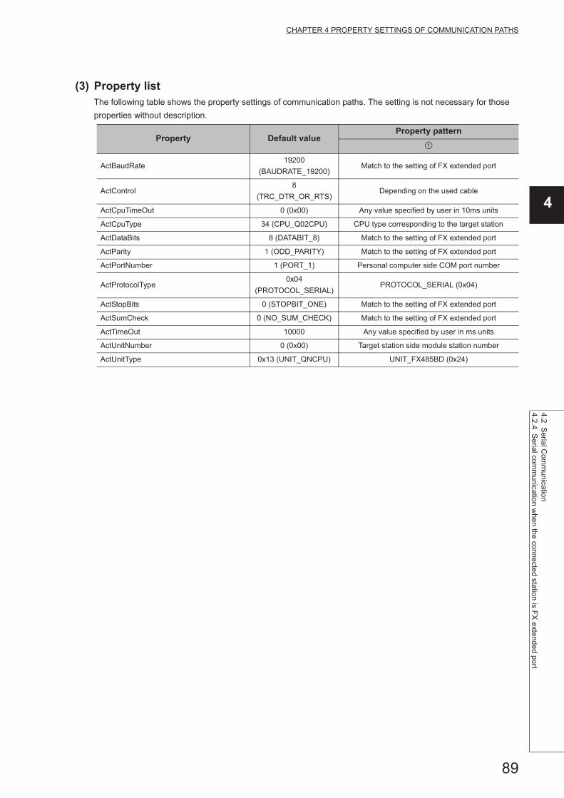
89
CHAPTER 4 PROPERTY SETTINGS OF COMMUNICATION PATHS
4
4.2 Serial C
omm
unicatio
n4.2.4 S
erial com
munication w
hen the connected statio
n is FX
extended port
(3) Property listThe following table shows the property settings of communication paths. The setting is not necessary for those
properties without description.
Property Default valueProperty pattern
ActBaudRate19200
(BAUDRATE_19200)Match to the setting of FX extended port
ActControl8
(TRC_DTR_OR_RTS)Depending on the used cable
ActCpuTimeOut 0 (0x00) Any value specified by user in 10ms units
ActCpuType 34 (CPU_Q02CPU) CPU type corresponding to the target station
ActDataBits 8 (DATABIT_8) Match to the setting of FX extended port
ActParity 1 (ODD_PARITY) Match to the setting of FX extended port
ActPortNumber 1 (PORT_1) Personal computer side COM port number
ActProtocolType0x04
(PROTOCOL_SERIAL)PROTOCOL_SERIAL (0x04)
ActStopBits 0 (STOPBIT_ONE) Match to the setting of FX extended port
ActSumCheck 0 (NO_SUM_CHECK) Match to the setting of FX extended port
ActTimeOut 10000 Any value specified by user in ms units
ActUnitNumber 0 (0x00) Target station side module station number
ActUnitType 0x13 (UNIT_QNCPU) UNIT_FX485BD (0x24)

90
4.3 Ethernet Communication
4.3.1 Ethernet communication when the connected station is R series-compatible E71 (TCP)
(1) Configuration
(2) Property patterns
*1 : Relayed stations cannot be accessed via R motion CPU.*2 : Since CC-Link IE Controller Network is not supported, RCPU relayed by CC-Link IE Controller Network cannot be
accessed.*3 : Only CPU No.2 or later in a multiple CPU configuration can be accessed.
Connected station
CPURelayed network
Relayed station CPU
RCPUR motion
CPURCPU
R motion
CPU
*1,*3
CC IE Control
CC IE Field*2
MELSECNET/H
Ethernet
Serial communication
CC-Link
Connected station
CPU
Relayed network
Relayed station CPU
RCPUR motion
CPU
QCPU
(Q mode)
C
Controller
module
LCPU QSCPUQ motion
CPUFXCPU
*1,*3
CC IE Control
CC IE Field
MELSECNET/H
Ethernet
Serial communication
CC-Link
: Accessible (The number in the circle is the property pattern number.), : Inaccessible
Personal computer
Connected
station CPU
R series-
compatible E71
Relayed
module
Relayed network
Relayed
station CPU
Relayed
module

91
CHAPTER 4 PROPERTY SETTINGS OF COMMUNICATION PATHS
4
4.3 Ethernet C
omm
unication
4.3.1 Ethe
rnet comm
unication w
hen the connected station is R series-com
patible E71
(TC
P)
(3) Property listThe following table shows the property settings of communication paths. The setting is not necessary for those
properties without description.
Property Default valueProperty pattern
*1
ActConnectUnit
Number0 (0x00) Fixed to 0 (0x00)
Connected station side
module station numberFixed to 0 (0x00) Fixed to 0 (0x00)
ActCpuType34
(CPU_Q02CPU)CPU type corresponding to the target station
ActDestination
IONumber *30 (0x00) Fixed to 0 (0x00) Fixed to 0 (0x00)
Target station side
For single CPU
Fixed to 1023 (0x3FF)
For multiple CPUs
Connected CPU:
1023 (0x3FF)
No. 1: 992 (0x3E0)
No. 2: 993 (0x3E1)
No. 3: 994 (0x3E2)
No. 4: 995 (0x3E3)
Target station side
For single CPU
Fixed to 1023 (0x3FF)
For multiple CPUs
Connected CPU:
1023 (0x3FF)
No. 1: 992 (0x3E0)
No. 2: 993 (0x3E1)
No. 3: 994 (0x3E2)
No. 4: 995 (0x3E3)
For Redundant CPU
Control system:
976 (0x3D0)
No specification:
1023 (0x3FF)
ActDestination
PortNumber 0(0x00)
5002 for MELSOFT connection
Any port number for OPS connection. *2
ActDidProperty
Bit1 (0x01) Fixed to 1 (0x01) Fixed to 1 (0x01) Fixed to 0 (0x00) Fixed to 0 (0x00)
ActDsidProperty
Bit1 (0x01) Fixed to 1 (0x01) Fixed to 1 (0x01) Fixed to 0 (0x00) Fixed to 0 (0x00)
ActHostAddress 1.1.1.1 Host name or IP address of the connected station side module
ActIONumber *3 1023 (0x3FF)
For single CPU
Fixed to 1023 (0x3FF)
For multiple CPUs
Connected CPU:
1023 (0x3FF)
No. 1: 992 (0x3E0)
No. 2: 993 (0x3E1)
No. 3: 994 (0x3E2)
No. 4: 995 (0x3E3)
For Redundant CPU
Control system:
976 (0x3D0)
No specification:
1023 (0x3FF)
Target station side
For single CPU
Fixed to 1023 (0x3FF)
For multiple CPUs
Connected CPU:
1023 (0x3FF)
No. 1: 992 (0x3E0)
No. 2: 993 (0x3E1)
No. 3: 994 (0x3E2)
No. 4: 995 (0x3E3)
For Redundant CPU
Control system:
976 (0x3D0)
No specification:
1023 (0x3FF)
Connected station side
module I/O address
Connected station side
module I/O address
ActMultiDrop
ChannelNumber *40 (0x00) Fixed to 0 (0x00) Fixed to 0 (0x00)
Multi-drop channel
numberFixed to 0 (0x00)
ActNetwork
Number *50 (0x00)
Target station side
module network
number
Target station side
module network
number
Connected station side
R series-compatible
E71 network number
Connected station side
R series-compatible
E71 network number
ActPassword Null Password set to R series-compatible E71 on the connected station side

92
*1 : Note the following considerations when accessing via Ethernet module (R series-compatible E71). • For ActNetworkNumber and ActStationNumber, specify the value set in the parameter setting of the target station side R series-
compatible E71. • Set "Station No. IP information" in the parameter setting of R series-compatible E71. When setting the parameter, specify the
setting other than the automatic response system (any of the IP address calculation system, table conversion system, and combined system) for "Station No. IP information system".
*2 : When using the OPS connection function for Redundant CPU, specify any port number that was set to the network parameter of the CPU.
(The setting range is 1025 port number 4999 or 5003 port number 65534) *3 : For the I/O address, specify the value of the actual start I/O number divided by 16.*4 : Specify the following value for the channel number to be multi-drop linked.
0: Default channel of module1: Channel 12: Channel 2
*5 : When the property pattern is or , specify the value set in the target station side parameter for ActNetworkNumber and ActStationNumber.
*6 : Specify the station number on the personal computer side to avoid the same station number set for R series-compatible E71 within the same Ethernet loop.
ActProtocolType
0x04
(PROTOCOL_
SERIAL)
PROTOCOL_TCPIP(0x05)
ActPacketType0x01(PACKET_
PLC1)PACKET_PLC1
ActPortNumber 1 (PORT_1) Personal computer side COM port number
ActBaudRate
19200
(BAUDRATE_
19200)
Fixed to 0 (0x00)
ActCpuTimeOut 0(0x00) Fixed to 0 (0x00)
ActControl8(TRC_DTR_
OR_RTS)Fixed to 0 (0x00)
ActDataBits 8(DATABIT_8) Fixed to 0 (0x00)
ActParity1(ODD_
PARITY)Fixed to 0 (0x00)
ActStopBits0(STOPBIT_
ONE)Fixed to 0 (0x00)
ActSumCheck0(NO_SUM_
CHECK)Fixed to 0 (0x00)
ActIntelligent
PreferenceBit0 (0x00) Fixed to 0 (0x00)
ActSource
NetworkNumber0(0x00) Personal computer side network number
ActSourceStation
Number *60(0x00) Personal computer side station number
ActStation
Number *5255 (0xFF)
Target station side
module station number
Target station side
module station number
Connected station side
R series-compatible
E71 station number
Connected station side
R series-compatible
E71 station number
ActThrough
NetworkType0 (0x00)
MELSECNET/10 is not included. : 0 (0x00)
MELSECNET/10 is included. : 1 (0x01)
ActTimeOut 10000 Any value specified by user in ms units
ActUnitNumber 0 (0x00) Fixed to 0 (0x00) Fixed to 0 (0x00)Target station side
module station number
Target station side
module station number
ActUnitType0x13
(UNIT_QNCPU)UNIT_RJ71EN71(0x1001)
Property Default valueProperty pattern
*1

93
CHAPTER 4 PROPERTY SETTINGS OF COMMUNICATION PATHS
4
4.3 Ethernet C
omm
unication
4.3.2 Ethe
rnet comm
unication w
hen the connected station is R series-com
patible E71
(UD
P)
4.3.2 Ethernet communication when the connected station is R series-compatible E71 (UDP)
(1) Configuration
(2) Property patterns
*1 : Relayed stations cannot be accessed via R motion CPU.*2 : Since CC-Link IE Controller Network is not supported, RCPU relayed by CC-Link IE Controller Network cannot be
accessed.*3 : Only CPU No.2 or later in a multiple CPU configuration can be accessed.
Connected station
CPURelayed network
Relayed station CPU
RCPUR motion
CPURCPU
R motion
CPU
*1,*3
CC IE Control
CC IE Field*2
MELSECNET/H
Ethernet
Serial communication
CC-Link
Connected station
CPU
Relayed network
Relayed station CPU
RCPUR motion
CPU
QCPU
(Q mode)
C
Controller
module
LCPU QSCPUQ motion
CPUFXCPU
*1,*3
CC IE Control
CC IE Field
MELSECNET/H
Ethernet
Serial communication
CC-Link
: Accessible (The number in the circle is the property pattern number.), : Inaccessible
Personal computer
Connected
station CPU
R series-
compatible E71
Relayed
module
Relayed network
Relayed
station CPU
Relayed
module

94
(3) Property listThe following table shows the property settings of communication paths. The setting is not necessary for those
properties without description.
Property Default valueProperty pattern
*1
ActConnectUnit
Number0 (0x00) Fixed to 0 (0x00)
Connected station side
module station numberFixed to 0 (0x00) Fixed to 0 (0x00)
ActCpuType34
(CPU_Q02CPU)CPU type corresponding to the target station
ActDestination
IONumber *30 (0x00) Fixed to 0 (0x00) Fixed to 0 (0x00)
Target station side
For single CPU
Fixed to 1023 (0x3FF)
For multiple CPUs
Connected CPU:
1023 (0x3FF)
No. 1: 992 (0x3E0)
No. 2: 993 (0x3E1)
No. 3: 994 (0x3E2)
No. 4: 995 (0x3E3)
Target station side
For single CPU
Fixed to 1023 (0x3FF)
For multiple CPUs
Connected CPU:
1023 (0x3FF)
No. 1: 992 (0x3E0)
No. 2: 993 (0x3E1)
No. 3: 994 (0x3E2)
No. 4: 995 (0x3E3)
For Redundant CPU
Control system:
976 (0x3D0)
No specification:
1023 (0x3FF)
ActDestination
PortNumber 0(0x00)
For communication with IP address specified: 5001
For direct communication without IP address specified: 5003
ActDidProperty
Bit1 (0x01) Fixed to 1 (0x01) Fixed to 1 (0x01) Fixed to 0 (0x00) Fixed to 0 (0x00)
ActDsidProperty
Bit1 (0x01) Fixed to 1 (0x01) Fixed to 1 (0x01) Fixed to 0 (0x00) Fixed to 0 (0x00)
ActHostAddress 1.1.1.1For communication with IP address specified: Host name or IP address of the connected station side
For direct communication without IP address specified: 255.255.255.255
ActIONumber *3 1023 (0x3FF)
For single CPU
Fixed to 1023 (0x3FF)
For multiple CPUs
Connected CPU:
1023 (0x3FF)
No. 1: 992 (0x3E0)
No. 2: 993 (0x3E1)
No. 3: 994 (0x3E2)
No. 4: 995 (0x3E3)
For Redundant CPU
Control system:
976 (0x3D0)
No specification:
1023 (0x3FF)
Target station side
For single CPU
Fixed to 1023 (0x3FF)
For multiple CPUs
Connected CPU:
1023 (0x3FF)
No. 1: 992 (0x3E0)
No. 2: 993 (0x3E1)
No. 3: 994 (0x3E2)
No. 4: 995 (0x3E3)
For Redundant CPU
Control system:
976 (0x3D0)
No specification:
1023 (0x3FF)
Connected station side
module I/O address
Connected station side
module I/O address
ActMultiDrop
ChannelNumber *40 (0x00) Fixed to 0 (0x00) Fixed to 0 (0x00)
Multi-drop channel
numberFixed to 0 (0x00)
ActNetwork
Number *50 (0x00)
Target station side
module network
number
Target station side
module network
number
Connected station side
R series-compatible
E71 network number
Connected station side
R series-compatible
E71 network number
ActPassword Null Password set to R series-compatible E71 on the connected station side

95
CHAPTER 4 PROPERTY SETTINGS OF COMMUNICATION PATHS
4
4.3 Ethernet C
omm
unication
4.3.2 Ethe
rnet comm
unication w
hen the connected station is R series-com
patible E71
(UD
P)
*1 : Note the following considerations when accessing via Ethernet module (R series-compatible E71). • For ActNetworkNumber and ActStationNumber, specify the value set in the parameter setting of the target station side R series-
compatible E71. • Set "Station No. IP information" in the parameter setting of R series-compatible E71. When setting the parameter, specify the
setting other than the automatic response system (any of the IP address calculation system, table conversion system, and combined system) for "Station No. IP information system".
*2 : When using the OPS connection function for Redundant CPU, specify any port number that was set to the network parameter of the CPU.
(The setting range is 1025 port number 4999 or 5003 port number 65534) *3 : For the I/O address, specify the value of the actual start I/O number divided by 16.*4 : Specify the following value for the channel number to be multi-drop linked.
0: Default channel of module1: Channel 12: Channel 2
*5 : When the property pattern is or , specify the value set in the target station side parameter for ActNetworkNumber and ActStationNumber.
*6 : Specify the station number on the personal computer side to avoid the same station number set for R series-compatible E71 within the same Ethernet loop.
ActPortNumber 1 (PORT_1) Personal computer side COM port number
ActProtocolType
0x04
(PROTOCOL_
SERIAL)
PROTOCOL_UDPIP(0x08)
ActPacketType0x01(PACKET_
PLC1)PACKET_PLC1
ActBaudRate
19200
(BAUDRATE_
19200)
Fixed to 0 (0x00)
ActCpuTimeOut 0(0x00) Fixed to 0 (0x00)
ActControl8(TRC_DTR_
OR_RTS)Fixed to 0 (0x00)
ActDataBits 8(DATABIT_8) Fixed to 0 (0x00)
ActParity1(ODD_
PARITY)Fixed to 0 (0x00)
ActStopBits0(STOPBIT_
ONE)Fixed to 0 (0x00)
ActSumCheck0(NO_SUM_
CHECK)Fixed to 0 (0x00)
ActIntelligent
PreferenceBit0 (0x00) Fixed to 0 (0x00)
ActSource
NetworkNumber0(0x00) Personal computer side network number
ActSourceStation
Number *60(0x00) Personal computer side station number
ActStation
Number *5255 (0xFF)
Target station side
module station number
Target station side
module station number
Connected station side
R series-compatible
E71 station number
Connected station side
R series-compatible
E71 station number
ActThrough
NetworkType0 (0x00)
MELSECNET/10 is not included. : 0 (0x00)
MELSECNET/10 is included. : 1 (0x01)
ActTimeOut 10000 Any value specified by user in ms units
ActUnitNumber 0 (0x00) Fixed to 0 (0x00) Fixed to 0 (0x00)Target station side
module station number
Target station side
module station number
ActUnitType0x13
(UNIT_QNCPU)
For communication with IP address specified: UNIT_RJ71EN71(0x1001)
For direst communication without IP address specified: UNIT_RJ71EN71_DIRECT(0x1005)
Property Default valueProperty pattern
*1

96
4.3.3 Ethernet communication when the connected station is Q series-compatible E71 (TCP)
(1) Configuration
(2) Property patterns
*1 : Relayed stations cannot be accessed when the Q motion CPU is Q172CPU, Q173CPU, Q172HCPU, or Q173HCPU.*2 : Relayed stations cannot be accessed via QSCPU or Q motion CPU.*3 : Since CC-Link IE Field Network is not supported, R motion CPU, Q12DCCPU-V (Basic mode), QSCPU, and Q motion CPU relayed by
CC-Link IE Field Network cannot be accessed.*4 : Since CC-Link IE Controller Network is not supported, LCPU relayed by CC-Link IE Controller Network cannot be accessed.*5 : For Redundant CPU, serial communication modules on the main base cannot be accessed.*6 : Only CPU No.2 or later in a multiple CPU configuration can be accessed.
Connected station CPU
Relayed
network
Relayed station
CPU
QCPU
(Q mode)
C
Controller
module
QSCPU
Q
motion
CPU
RCPUR motion
CPU
*6 *2 *1,*2
CC IE Control
CC IE Field
MELSECNET/H
Ethernet
Serial
communication
CC-Link
Connected station CPU
Relayed
network
Relayed station CPU
QCPU
(Q mode)
C
Controller
module
QSCPU
Q
motion
CPU
QCPU
(Q mode)
C
Controller
module
LCPU QSCPU
Q
motion
CPU
FXCPU
*6 *2 *1,*2
CC IE Control
CC IE Field *3 *4 *2,*3 *3
MELSECNET/H *2
Ethernet *2
Serial
communication*5
CC-Link
: Accessible (The number in the circle is the property pattern number.), : Inaccessible
Personal computer
Connected
station CPU
Q series-compatible
E71
Relayed
module
Relayed network
Relayed
station CPU
Relayed
module

97
CHAPTER 4 PROPERTY SETTINGS OF COMMUNICATION PATHS
4
4.3 Ethernet C
omm
unication
4.3.3 Ethe
rnet comm
unication w
hen the connected station is Q se
ries-com
patible E
71 (TC
P)
(3) Property listThe following table shows the property settings of communication paths. The setting is not necessary for those
properties without description.
Property Default valueProperty pattern
ActConnectUnit
Number0 (0x00) Fixed to 0 (0x00)
Connected station side
module station numberFixed to 0 (0x00) Fixed to 0 (0x00)
ActCpuType34
(CPU_Q02CPU)CPU type corresponds to the target station
ActDestination
IONumber0 (0x00) Fixed to 0 (0x00) Fixed to 0 (0x00)
Target station side
For single CPU
Fixed to 1023 (0x3FF)
For multiple CPUs
Connected CPU:
1023 (0x3FF)
No. 1: 992 (0x3E0)
No. 2: 993 (0x3E1)
No. 3: 994 (0x3E2)
No. 4: 995 (0x3E3)
For Redundant CPU
Control system:
976 (0x3D0)
No specification:
1023 (0x3FF)
Target station side
For single CPU
Fixed to 1023 (0x3FF)
For multiple CPUs
Connected CPU:
1023 (0x3FF)
No. 1: 992 (0x3E0)
No. 2: 993 (0x3E1)
No. 3: 994 (0x3E2)
No. 4: 995 (0x3E3)
For Redundant CPU
Control system:
976 (0x3D0)
No specification:
1023 (0x3FF)
ActDestination
PortNumber0 (0x00)
5002 for MELSOFT connection
Any port number for OPS connection*1
ActDidProperty
Bit1 (0x01) Fixed to 1 (0x01) Fixed to 1 (0x01) Fixed to 0 (0x00) Fixed to 0 (0x00)
ActDsidProperty
Bit1 (0x01) Fixed to 1 (0x01) Fixed to 1 (0x01) Fixed to 0 (0x00) Fixed to 0 (0x00)
ActHostAddress 1.1.1.1 Host name or IP address of the connected station side module
ActIONumber *2 1023 (0x3FF)
Target station side
For single CPU
Fixed to 1023 (0x3FF)
For multiple CPUs
Connected CPU:
1023 (0x3FF)
No. 1: 992 (0x3E0)
No. 2: 993 (0x3E1)
No. 3: 994 (0x3E2)
No. 4: 995 (0x3E3)
For Redundant CPU
Control system:
976 (0x3D0)
No specification:
1023 (0x3FF)
Target station side
For single CPU
Fixed to 1023 (0x3FF)
For multiple CPUs
Connected CPU:
1023 (0x3FF)
No. 1: 992 (0x3E0)
No. 2: 993 (0x3E1)
No. 3: 994 (0x3E2)
No. 4: 995 (0x3E3)
For Redundant CPU
Control system:
976 (0x3D0)
No specification:
1023 (0x3FF)
Connected station
side relayed
module I/O
address
Connected station
side relayed
module I/O
address
ActMultiDrop
ChannelNumber *30 (0x00) Fixed to 0 (0x00) Fixed to 0 (0x00)
Multi-drop channel
numberFixed to 0 (0x00)
ActNetwork
Number *40 (0x00)
Target station side
module network
number
Target station side
module network
number
Connected station side
Q series-compatible
E71 network number
Connected station side
Q series-compatible
E71 network number
ActPassword Null Password set to Q series-compatible E71 on the connected station side

98
*1 : When using the OPS connection function for Redundant CPU, specify any port number that was set to the network parameter of the
CPU. (The setting range is 1025 port number 4999 or 5003 port number 65534)
*2 : For the I/O address, specify the value of the actual start I/O number divided by 16.*3 : Specify the following value for the channel number to be multi-drop linked.
0: Default channel of module1: Channel 12: Channel 2
*4 : When the property pattern is or , specify the value set in the target station side parameter for ActNetworkNumber and ActStationNumber.
*5 : Specify the station number on the personal computer side to avoid the same station number set for Q series-compatible E71 within the same Ethernet loop.
ActProtocolType
0x04
(PROTOCOL_
SERIAL)
PROTOCOL_TCPIP (0x05)
ActSource
NetworkNumber0 (0x00) Personal computer side network number
ActSourceStation
Number *50 (0x00) Personal computer side station number
ActStation
Number *4255 (0xFF)
Target station side
module network
number
Target station side
module network
number
Connected station side
Q series-compatible
E71 network number
Connected station side
Q series-compatible
E71 network number
ActThrough
NetworkType0 (0x00)
MELSECNET/10 is not included. : 0 (0x00)
MELSECNET/10 is included. : 1 (0x01)
ActTimeOut 10000 Any value specified by user in ms units.
ActUnitNumber 0 (0x00) Fixed to 0 (0x00) Fixed to 0 (0x00)Target station side
module station number
Target station side
module station number
ActUnitType0x13
(UNIT_QNCPU)UNIT_QJ71E71 (0x1A)
Property Default valueProperty pattern

99
CHAPTER 4 PROPERTY SETTINGS OF COMMUNICATION PATHS
4
4.3 Ethernet C
omm
unication
4.3.4 Ethe
rnet comm
unication w
hen the connected station is Q se
ries-com
patible E
71 (UD
P)
4.3.4 Ethernet communication when the connected station is Q series-compatible E71 (UDP)
(1) Configuration
(2) Property patterns
*1 : Relayed stations cannot be accessed when the Q motion CPU is Q172CPU, Q173CPU, Q172HCPU, or Q173HCPU.*2 : Relayed stations cannot be accessed via QSCPU or Q motion CPU.*3 : Since CC-Link IE Field Network is not supported, R motion CPU, Q12DCCPU-V (Basic mode), QSCPU, and Q motion CPU relayed by
CC-Link IE Field Network cannot be accessed.*4 : Since CC-Link IE Controller Network is not supported, LCPU relayed by CC-Link IE Controller Network cannot be accessed.*5 : For Redundant CPU, serial communication modules on the main base cannot be accessed.*6 : Only CPU No.2 or later in a multiple CPU configuration can be accessed.*7 : Since C Controller module is not supported by MELSOFT direct connection, Ethernet port direct connection is not applicable.
Connected station CPU
Relayed
network
Relayed station
CPU
QCPU
(Q mode)
C
Controller
module
QSCPU
Q
motion
CPU
RCPUR motion
CPU
*6,*7 *2 *1,*2
CC IE Control
CC IE Field
MELSECNET/H
Ethernet
Serial
communication
CC-Link
Connected station CPU
Relayed
network
Relayed station CPU
QCPU
(Q mode)
C
Controller
module
QSCPU
Q
motion
CPU
QCPU
(Q mode)
C
Controller
module
LCPU QSCPU
Q
motion
CPU
FXCPU
*6,*7 *2 *1,*2
CC IE Control
CC IE Field *3 *4 *2,*3 *3
MELSECNET/H *2
Ethernet *2
Serial
communication*5
CC-Link
: Accessible (The number in the circle is the property pattern number.), : Inaccessible
Personal computer
Connected
station CPU
Q series-compatible
E71
Relayed
module
Relayed network
Relayed
station CPU
Relayed
module

100
(3) Property listThe following table shows the property settings of communication paths. The setting is not necessary for those
properties without description.
Property Default valueProperty pattern
ActConnectUnit
Number0 (0x00) Fixed to 0 (0x00)
Connected station side
module station numberFixed to 0 (0x00) Fixed to 0 (0x00)
ActCpuType34
(CPU_Q02CPU)CPU type corresponding to the target station
ActDestination
IONumber0 (0x00) Fixed to 0 (0x00) Fixed to 0 (0x00)
Target station side
For single CPU
Fixed to 1023 (0x3FF)
For multiple CPUs
Connected CPU:
1023 (0x3FF)
No. 1: 992 (0x3E0)
No. 2: 993 (0x3E1)
No. 3: 994 (0x3E2)
No. 4: 995 (0x3E3)
For Redundant CPU
Control system:
976 (0x3D0)
No specification:
1023 (0x3FF)
Target station side
For single CPU
Fixed to 1023 (0x3FF)
For multiple CPUs
Connected CPU:
1023 (0x3FF)
No. 1: 992 (0x3E0)
No. 2: 993 (0x3E1)
No. 3: 994 (0x3E2)
No. 4: 995 (0x3E3)
For Redundant CPU
Control system:
976 (0x3D0)
No specification:
1023 (0x3FF)
ActDidProperty
Bit1 (0x01) Fixed to 1 (0x01) Fixed to 1 (0x01) Fixed to 0 (0x00) Fixed to 0 (0x00)
ActDsidProperty
Bit1 (0x01) Fixed to 1 (0x01) Fixed to 1 (0x01) Fixed to 0 (0x00) Fixed to 0 (0x00)
ActHostAddress 1.1.1.1 Host name or IP address of the connected station side module
ActIONumber*1 1023 (0x3FF)
Target station side
For single CPU
Fixed to 1023 (0x3FF)
For multiple CPUs
Connected CPU:
1023 (0x3FF)
No. 1: 992 (0x3E0)
No. 2: 993 (0x3E1)
No. 3: 994 (0x3E2)
No. 4: 995 (0x3E3)
For Redundant CPU
Control system:
976 (0x3D0)
No specification:
1023 (0x3FF)
Target station side
For single CPU
Fixed to 1023 (0x3FF)
For multiple CPUs
Connected CPU:
1023 (0x3FF)
No. 1: 992 (0x3E0)
No. 2: 993 (0x3E1)
No. 3: 994 (0x3E2)
No. 4: 995 (0x3E3)
For Redundant CPU
Control system:
976 (0x3D0)
No specification:
1023 (0x3FF)
Connected station
side relayed
module I/O
address
Connected station
side relayed
module I/O
address
ActMultiDrop
ChannelNumber*20 (0x00) Fixed to 0 (0x00) Fixed to 0 (0x00)
Multi-drop channel
numberFixed to 0 (0x00)
ActNetwork
Number*30 (0x00)
Target station side
module network
number
Target station side
module network
number
Connected station side
Q series-compatible
E71 network number
Connected station side
Q series-compatible
E71 network number
ActPassword Null Password set to Q series-compatible E71 on the connected station side
ActPortNumber*4 1 (PORT_1) Personal computer side port number

101
CHAPTER 4 PROPERTY SETTINGS OF COMMUNICATION PATHS
4
4.3 Ethernet C
omm
unication
4.3.4 Ethe
rnet comm
unication w
hen the connected station is Q se
ries-com
patible E
71 (UD
P)
*1 : For the I/O address, specify the value of the actual start I/O number divided by 16.*2 : Specify the following value for the channel number to be multi-drop linked.
0: Default channel of module1: Channel 12: Channel 2
*3 : When the property pattern is or , specify the value set in the target station side parameter for ActNetworkNumber and ActStationNumber.
*4 : Do not use 1 to 1024 of ActPortNumber.*5 : Specify the station number on the personal computer side to avoid the same station number set for Q series-compatible E71 within the
same Ethernet loop.
ActProtocolType
0x04
(PROTOCOL_
SERIAL)
PROTOCOL_UDPIP (0x08)
ActSource
NetworkNumber*40 (0x00) Personal computer side network number
ActSourceStation
Number*50 (0x00) Personal computer side station number
ActStation
Number*3255 (0xFF)
Target station side
module network
number
Target station side
module network
number
Connected station side
Q series-compatible
E71 network number
Connected station side
Q series-compatible
E71 network number
ActThrough
NetworkType0 (0x00)
MELSECNET/10 is not included. : 0 (0x00)
MELSECNET/10 is included. : 1 (0x01)
ActTimeOut 10000 Any value specified by user in ms units.
ActUnitNumber 0 (0x00) Fixed to 0 (0x00) Fixed to 0 (0x00)Target station side
module station number
Target station side
module station number
ActUnitType0x13
(UNIT_QNCPU)UNIT_QJ71E71 (0x1A)
Property Default valueProperty pattern

102
4.3.5 Ethernet communication when the connected station is RCPU (TCP)
(1) Configuration
(2) Property patterns
*1 : Relayed stations cannot be accessed via R motion CPU.*2 : Since CC-Link IE Controller Network is not supported, RCPU relayed by CC-Link IE Controller Network cannot be
accessed.*3 : Only CPU No.2 or later in a multiple CPU configuration can be accessed.
Connected station
CPURelayed network
Relayed station CPU
RCPUR motion
CPURCPU
R motion
CPU
*1,*3
CC IE Control
CC IE Field*2
MELSECNET/H
Ethernet
Serial communication
CC-Link
Connected station
CPU
Relayed network
Relayed station CPU
RCPUR motion
CPU
QCPU
(Q mode)
C
Controller
module
LCPU QSCPUQ motion
CPUFXCPU
*1,*3
CC IE Control
CC IE Field
MELSECNET/H
Ethernet
Serial communication
CC-Link
: Accessible (The number in the circle is the property pattern number.), : Inaccessible
Connected
station CPU
Relayed
module
Relayed network
Relayed
station CPU
Relayed
modulePersonal computer

103
CHAPTER 4 PROPERTY SETTINGS OF COMMUNICATION PATHS
4
4.3 Ethernet C
omm
unication
4.3.5 Ethe
rnet comm
unication w
hen the connected station is RC
PU
(TC
P)
(3) Property listThe following table shows the property settings of communication paths. The setting is not necessary for those
properties without description.
Property Default valueProperty pattern
*1
ActCpuType34
(CPU_Q02CPU)CPU type corresponding to the target station
ActDestination
IONumber *20 (0x00) Fixed to 0 (0x00) Fixed to 0 (0x00)
Target station side
For single CPU
Fixed to 1023 (0x3FF)
For multiple CPUs
Connected CPU:
1023 (0x3FF)
No. 1: 992 (0x3E0)
No. 2: 993 (0x3E1)
No. 3: 994 (0x3E2)
No. 4: 995 (0x3E3)
Target station side
For single CPU
Fixed to 1023 (0x3FF)
For multiple CPUs
Connected CPU:
1023 (0x3FF)
No. 1: 992 (0x3E0)
No. 2: 993 (0x3E1)
No. 3: 994 (0x3E2)
No. 4: 995 (0x3E3)
For Redundant CPU
Control system:
976 (0x3D0)
No specification:
1023 (0x3FF)
ActDestination
PortNumber0(0x00) 5007
ActDidProperty
Bit1 (0x01) Fixed to 1 (0x01) Fixed to 1 (0x01) Fixed to 0 (0x00) Fixed to 0 (0x00)
ActDsidProperty
Bit1 (0x01) Fixed to 1 (0x01) Fixed to 1 (0x01) Fixed to 0 (0x00) Fixed to 0 (0x00)
ActHostAddress 1.1.1.1 Host name or IP address of the connected station side module
ActIntelligent
PreferenceBit0(0x00) Fixed to 0 (0x00) Fixed to 0 (0x00)
Target station
RCPU, R motion CPU,
QCPU (Q mode),
C Controller module,
LCPU : 1 (0x01)
Other than the
above : 0 (0x00)
Target station
RCPU, R motion CPU,
QCPU (Q mode),
C Controller module,
LCPU : 1 (0x01)
Other than the
above : 0 (0x00)
ActIONumber*2 1023 (0x3FF)
For single CPU
Fixed to 1023 (0x3FF)
For multiple CPUs
Connected CPU:
1023 (0x3FF)
No. 1: 992 (0x3E0)
No. 2: 993 (0x3E1)
No. 3: 994 (0x3E2)
No. 4: 995 (0x3E3)
Target station side
For single CPU
Fixed to 1023 (0x3FF)
For multiple CPUs
Connected CPU:
1023 (0x3FF)
No. 1: 992 (0x3E0)
No. 2: 993 (0x3E1)
No. 3: 994 (0x3E2)
No. 4: 995 (0x3E3)
For Redundant CPU
Control system:
976 (0x3D0)
No specification:
1023 (0x3FF)
Connected station
side relayed
module I/O
address
Connected station
side relayed
module I/O
address
ActMultiDrop
ChannelNumber *30 (0x00) Fixed to 0 (0x00) Fixed to 0 (0x00)
Multi-drop channel
numberFixed to 0 (0x00)

104
*1 : Note the following considerations when accessing via Ethernet module (R series-compatible E71). • For ActNetworkNumber and ActStationNumber, specify the value set in the parameter setting of the target station side R series-
compatible E71. • Set "Station No. IP information" in the parameter setting of R series-compatible E71. When setting the parameter, specify the
setting other than the automatic response system (any of the IP address calculation system, table conversion system, and combined system) for "Station No. IP information system".
*2 : For the I/O address, specify the value of the actual start I/O number divided by 16.*3 : Specify the following value for the channel number to be multi-drop linked.
0: Default channel of module1: Channel 12: Channel 2
*4 : When the property pattern is , specify the value set in the target station side parameter for ActNetworkNumber and ActStationNumber.
ActNetwork
Number *40 (0x00) Fixed to 0 (0x00)
Target station side
module network
number
Fixed to 0 (0x00) Fixed to 0 (0x00)
ActPassword Null Password set to the connected station side
ActProtocolType
0x04
(PROTOCOL_
SERIAL)
PROTOCOL_TCPIP(0x05)
ActStation
Number *4255 (0xFF) Fixed to 255 (0xFF)
Target station side
module station numberFixed to 255 (0xFF) Fixed to 255 (0xFF)
ActThrough
NetworkType0 (0x00)
MELSECNET/10 is not included. : 0 (0x00)
MELSECNET/10 is included. : 1 (0x01)
ActTimeOut 10000 Any value specified by user in ms units.
ActUnitNumber 0 (0x00) Fixed to 0 (0x00) Fixed to 0 (0x00)Target station side
module station number
Target station side
module station number
ActUnitType0x13
(UNIT_QNCPU)UNIT_RETHER(0x1002)
Property Default valueProperty pattern
*1
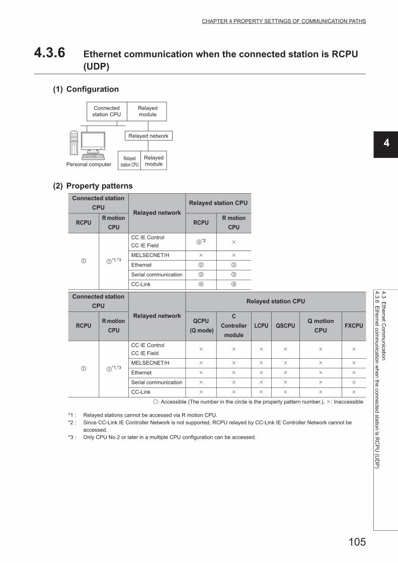
105
CHAPTER 4 PROPERTY SETTINGS OF COMMUNICATION PATHS
4
4.3 Ethernet C
omm
unication
4.3.6 Ethe
rnet comm
unication w
hen the connected station is RC
PU
(UD
P)
4.3.6 Ethernet communication when the connected station is RCPU (UDP)
(1) Configuration
(2) Property patterns
*1 : Relayed stations cannot be accessed via R motion CPU.*2 : Since CC-Link IE Controller Network is not supported, RCPU relayed by CC-Link IE Controller Network cannot be
accessed.*3 : Only CPU No.2 or later in a multiple CPU configuration can be accessed.
Connected station
CPURelayed network
Relayed station CPU
RCPUR motion
CPURCPU
R motion
CPU
*1,*3
CC IE Control
CC IE Field*2
MELSECNET/H
Ethernet
Serial communication
CC-Link
Connected station
CPU
Relayed network
Relayed station CPU
RCPUR motion
CPU
QCPU
(Q mode)
C
Controller
module
LCPU QSCPUQ motion
CPUFXCPU
*1,*3
CC IE Control
CC IE Field
MELSECNET/H
Ethernet
Serial communication
CC-Link
: Accessible (The number in the circle is the property pattern number.), : Inaccessible
Connected
station CPU
Relayed
module
Relayed network
Relayed
station CPU
Relayed
modulePersonal computer

106
(3) Property listThe following table shows the property settings of communication paths. The setting is not necessary for those
properties without description.
Property Default valueProperty pattern
*1
ActCpuType34
(CPU_Q02CPU)CPU type corresponding to the target station
ActDestination
IONumber *20 (0x00) Fixed to 0 (0x00) Fixed to 0 (0x00)
Target station side
For single CPU
Fixed to 1023 (0x3FF)
For multiple CPUs
Connected CPU:
1023 (0x3FF)
No. 1: 992 (0x3E0)
No. 2: 993 (0x3E1)
No. 3: 994 (0x3E2)
No. 4: 995 (0x3E3)
Target station side
For single CPU
Fixed to 1023 (0x3FF)
For multiple CPUs
Connected CPU:
1023 (0x3FF)
No. 1: 992 (0x3E0)
No. 2: 993 (0x3E1)
No. 3: 994 (0x3E2)
No. 4: 995 (0x3E3)
For Redundant CPU
Control system:
976 (0x3D0)
No specification:
1023 (0x3FF)
ActDidProperty
Bit1 (0x01) Fixed to 1 (0x01) Fixed to 1 (0x01) Fixed to 0 (0x00) Fixed to 0 (0x00)
ActDsidProperty
Bit1 (0x01) Fixed to 1 (0x01) Fixed to 1 (0x01) Fixed to 0 (0x00) Fixed to 0 (0x00)
ActIntelligent
PreferenceBit0(0x00) Fixed to 0 (0x00) Fixed to 0 (0x00)
Target station
RCPU, R motion CPU,
QCPU (Q mode),
C Controller module,
LCPU : 1 (0x01)
Other than the
above : 0 (0x00)
Target station
RCPU, R motion CPU,
QCPU (Q mode),
C Controller module,
LCPU : 1 (0x01)
Other than the
above : 0 (0x00)
ActHostAddress 1.1.1.1For communication with IP address specified: Host name or IP address of the connected station side
For direst communication without IP address specified: 255.255.255.255
ActDestination
PortNumber0(0x00)
For communication with IP address specified: 5006
For direct communication without IP address specified: Unused
ActIONumber*2 1023 (0x3FF)
For single CPU
Fixed to 1023 (0x3FF)
For multiple CPUs
Connected CPU:
1023 (0x3FF)
No. 1: 992 (0x3E0)
No. 2: 993 (0x3E1)
No. 3: 994 (0x3E2)
No. 4: 995 (0x3E3)
Target station side
For single CPU
Fixed to 1023 (0x3FF)
For multiple CPUs
Connected CPU:
1023 (0x3FF)
No. 1: 992 (0x3E0)
No. 2: 993 (0x3E1)
No. 3: 994 (0x3E2)
No. 4: 995 (0x3E3)
For Redundant CPU
Control system:
976 (0x3D0)
No specification:
1023 (0x3FF)
Connected station
side module I/O
address
Connected station
side module I/O
address

107
CHAPTER 4 PROPERTY SETTINGS OF COMMUNICATION PATHS
4
4.3 Ethernet C
omm
unication
4.3.6 Ethe
rnet comm
unication w
hen the connected station is RC
PU
(UD
P)
*1 : Note the following considerations when accessing via Ethernet module (R series-compatible E71). • For ActNetworkNumber and ActStationNumber, specify the value set in the parameter setting of the target station side R series-
compatible E71. • Set "Station No. IP information" in the parameter setting of R series-compatible E71. When setting the parameter, specify the
setting other than the automatic response system (any of the IP address calculation system, table conversion system, and combined system) for "Station No. IP information system".
*2 : For the I/O address, specify the value of the actual start I/O number divided by 16.*3 : Specify the following value for the channel number to be multi-drop linked.
0: Default channel of module1: Channel 12: Channel 2
*4 : When the property pattern is , specify the value set in the target station side parameter for ActNetworkNumber and ActStationNumber.
ActMultiDrop
ChannelNumber *30 (0x00) Fixed to 0 (0x00) Fixed to 0 (0x00)
Multi-drop channel
numberFixed to 0 (0x00)
ActNetwork
Number *40 (0x00) Fixed to 0 (0x00)
Target station side
module network
number
Fixed to 0 (0x00) Fixed to 0 (0x00)
ActPacketType0x01
(iPACKET_PLC1)PACKET_PLC1
ActPassword Null Password set to the connected station side
ActProtocolType
0x04
(PROTOCOL_
SERIAL)
PROTOCOL_UDPIP(0x08)
ActStation
Number *4255 (0xFF) Fixed to 255 (0xFF)
Target station side
module station numberFixed to 255 (0xFF) Fixed to 255 (0xFF)
ActThrough
NetworkType0 (0x00)
MELSECNET/10 is not included. : 0 (0x00)
MELSECNET/10 is included. : 1 (0x01)
ActTimeOut 10000 Any value specified by user in ms units.
ActUnitNumber 0 (0x00) Fixed to 0 (0x00) Fixed to 0 (0x00)Target station side
module station number
Target station side
module station number
ActUnitType0x13
(UNIT_QNCPU)
For communication with IP address specified: UNIT_RETHER(0x1002)
For direst communication without IP address specified: UNIT_RETHER_DIRECT(0x1003)
Property Default valueProperty pattern
*1

108
4.3.7 Ethernet communication when the connected station is FX5CPU (TCP)
(1) Configuration
(2) Property patterns
Connected
station CPURelayed network
Relayed station CPU
FX5CPU RCPUR motion
CPU
CC IE Control
CC IE Field
MELSECNET/H
Ethernet
Serial communication
CC-Link
Connected
station CPU
Relayed network
Relayed station CPU
FX5CPUQCPU
(Q mode)
C
Controller
module
LCPU QSCPUQ motion
CPUFXCPU
CC IE Control
CC IE Field
MELSECNET/H
Ethernet
Serial communication
CC-Link
: Accessible (The number in the circle is the property pattern number.), : Inaccessible
Connected
station CPU
Relayed
module
Relayed network
Relayed
station CPU
Relayed
modulePersonal computer

109
CHAPTER 4 PROPERTY SETTINGS OF COMMUNICATION PATHS
4
4.3 Ethernet C
omm
unication
4.3.7 Ethe
rnet comm
unication w
hen the connected station is FX
5CP
U (T
CP
)
(3) Property listThe following table shows the property settings of communication paths. The setting is not necessary for those
properties without description.
Property Default valueProperty pattern
ActBaudRate19200
(BAUDRATE_19200)0 (0x00)
ActControl 8(TRC_DTR_OR_RTS) 0 (0x00)
ActCpuType34
(CPU_Q02CPU)CPU type corresponding to the target station
ActDataBits 8(DATABIT_8) 0 (0x00)
ActDestinationPortNumber 0(0x00) 5562
ActHostAddress 1.1.1.1 Host name or IP address of the connected station side module
ActPacketType 0x01(PACKET_PLC1) PACKET_PLC1
ActPassword Null Remote password set to the connected station
ActPortNumber 1(PORT_1) 0 (0x00)
ActProtocolType0x04
(PROTOCOL_SERIAL)PROTOCOL_TCPIP(0x05)
ActStopBits 0(STOPBIT_ONE) 0 (0x00)
ActSumCheck 0(NO_SUM_CHECK) 0 (0x00)
ActThroughNetworkType 0(0x00) 1 (0x01)
ActTimeOut 10000 Any value specified by user in ms units
ActUnitType 0x13 (UNIT_QNCPU) UNIT_FXETHER(0x2001)
ActConnectWay TEL_AUTO_CONNECT 0
ActLineType LINETYPE_TONE 0
ActConnectionCDWaitTime 90 0
ActConnectionModemReportWaitTime 5 0
ActDisconnectionCDWaitTime 5 0
ActDisconnectionDelayTime 3 0
ActTransmissionDelayTime 0 0
ActATCommandResponsceWaitTime 1 0
ActPasswordCancelResponseWaitTime 5 0
ActATCommandPasswordCancelRetryTimes 3 0
ActCallbackCancelWaitTime 90 0
ActCallbackDelayTime 20 0
ActCallbackReceptionWaitingTimeOut 120 0
ActMxUnitSeries 0 0

110
4.3.8 Ethernet communication when the connected station is FX5CPU (UDP)
(1) Configuration
(2) Property patterns
Connected
station CPURelayed network
Relayed station CPU
FX5CPU RCPUR motion
CPU
CC IE Control
CC IE Field
MELSECNET/H
Ethernet
Serial communication
CC-Link
Connected
station CPU
Relayed network
Relayed station CPU
FX5CPUQCPU
(Q mode)
C
Controller
module
LCPU QSCPUQ motion
CPUFXCPU
CC IE Control
CC IE Field
MELSECNET/H
Ethernet
Serial communication
CC-Link
: Accessible (The number in the circle is the property pattern number.), : Inaccessible
Connected
station CPU
Relayed
module
Relayed network
Relayed
station CPU
Relayed
modulePersonal computer

111
CHAPTER 4 PROPERTY SETTINGS OF COMMUNICATION PATHS
4
4.3 Ethernet C
omm
unication
4.3.8 Ethe
rnet comm
unication w
hen the connected station is FX
5CP
U (U
DP
)
(3) Property listThe following table shows the property settings of communication paths. The setting is not necessary for those
properties without description.
Property Default valueProperty pattern
ActBaudRate19200
(BAUDRATE_19200)0 (0x00)
ActControl 8(TRC_DTR_OR_RTS) 0 (0x00)
ActCpuType34
(CPU_Q02CPU)CPU type corresponding to the target station
ActDataBits 8(DATABIT_8) 0 (0x00)
ActDestinationPortNumber 0(0x00) 5560
ActHostAddress 1.1.1.1 255.255.255.255
ActPacketType 0x01(PACKET_PLC1) PACKET_PLC1
ActPassword Null Remote password set to the connected station
ActPortNumber 1(PORT_1) 0 (0x00)
ActProtocolType0x04
(PROTOCOL_SERIAL)PROTOCOL_UDPIP(0x08)
ActStopBits 0(STOPBIT_ONE) 0 (0x00)
ActSumCheck 0(NO_SUM_CHECK) 0 (0x00)
ActThroughNetworkType 0(0x00) 1 (0x01)
ActTimeOut 10000 Any value specified by user in ms units
ActUnitType 0x13 (UNIT_QNCPU) UNIT_FXVETHER_DIRECT(0x2002)
ActConnectWay TEL_AUTO_CONNECT 0
ActLineType LINETYPE_TONE 0
ActConnectionCDWaitTime 90 0
ActConnectionModemReportWaitTime 5 0
ActDisconnectionCDWaitTime 5 0
ActDisconnectionDelayTime 3 0
ActTransmissionDelayTime 0 0
ActATCommandResponsceWaitTime 1 0
ActPasswordCancelResponseWaitTime 5 0
ActATCommandPasswordCancelRetryTimes 3 0
ActCallbackCancelWaitTime 90 0
ActCallbackDelayTime 20 0
ActCallbackReceptionWaitingTimeOut 120 0
ActMxUnitSeries 0 0

112
4.3.9 Ethernet communication when the connected station is built-in Ethernet port QCPU (TCP)
(1) Configuration
(2) Property patterns
Connected
station CPURelayed network
Relayed station CPU
QnUDE(H)
CPURCPU
R motion
CPU*4
CC IE Control
CC IE Field
MELSECNET/H
Ethernet
Serial communication
CC-Link
Connected
station CPU
Relayed network
Relayed station CPU
QnUDE(H)
CPU
QCPU
(Q mode)
C
Controller
module
LCPU QSCPUQ motion
CPUFXCPU
CC IE Control
CC IE Field *1 *2 *1 *1
MELSECNET/H
Ethernet
Serial communication *3
CC-Link
Connected
station CPU
Relayed
module
Relayed network
Relayed
station CPU
Relayed
modulePersonal computer

113
CHAPTER 4 PROPERTY SETTINGS OF COMMUNICATION PATHS
4
4.3 Ethernet C
omm
unication
4.3.9 Ethe
rnet comm
unication w
hen the connected station is built-in E
thernet port Q
CP
U (T
CP
)
*1 : Since CC-Link IE Field Network is not supported, R motion CPU, Q12DCCPU-V (Basic mode), QSCPU, and Q motion CPU relayed by CC-Link IE Field Network cannot be accessed.
*2 : Since CC-Link IE Controller Network is not supported, LCPU relayed by CC-Link IE Controller Network cannot be accessed.
*3 : For Redundant CPU, serial communication modules on the main base cannot be accessed.*4 : Only CPU No.2 or later in a multiple CPU configuration can be accessed.*5 : Q24DHCCPU-V and Q24DHCCPU-LS cannot be accessed because the communication route is not supported.*6 : Since C Controller module is not supported by MELSOFT direct connection, Ethernet port direct connection is not
applicable. *7 : For Q172D, Q173D, Q172DS, and Q173DS, only CPU No.2 or later in a multiple CPU configuration can be accessed.
Connected station CPU
Relayed network
Relayed station CPU
C Controller module
RCPUR motion
CPU*4
*4,*5,*6
CC IE ControlCC IE Field
MELSECNET/H
Ethernet
Serial communication
CC-Link
Connected station CPU
Relayed network
Relayed station CPU
C Controller module
QCPU (Q mode)
C Controller
moduleLCPU QSCPU
Q motion CPU
FXCPU
*4,*5,*6
CC IE ControlCC IE Field
*1 *2 *1 *1
MELSECNET/H
Ethernet
Serial communication
CC-Link
Connected station CPU
Relayed network
Relayed station CPU
Q motion CPU
RCPUR motion
CPU
*7
CC IE ControlCC IE Field
MELSECNET/H
Ethernet
Serial communication
CC-Link
Connected station CPU
Relayed network
Relayed station CPU
Q motion CPU
QCPU (Q mode)
C Controller
moduleLCPU QSCPU
Q motion CPU
FXCPU
*7
CC IE ControlCC IE Field
MELSECNET/H
Ethernet
Serial communication
CC-Link
: Accessible (The number in the circle is the property pattern number.), : Inaccessible

114
(3) Property listThe following table shows the property settings of communication paths. The setting is not necessary for those
properties without description.
Property Default valueProperty pattern
ActCpuType34
(CPU_Q02CPU)CPU type corresponding to the target station
ActDestination
IONumber0 (0x00) Fixed to 0 (0x00) Fixed to 0 (0x00)
Target station side
For single CPU
Fixed to 1023 (0x3FF)
For multiple CPUs
Connected CPU:
1023 (0x3FF)
No. 1: 992 (0x3E0)
No. 2: 993 (0x3E1)
No. 3: 994 (0x3E2)
No. 4: 995 (0x3E3)
For Redundant CPU
Control system:
976 (0x3D0)
No specification:
1023 (0x3FF)
Target station side
For single CPU
Fixed to 1023 (0x3FF)
For multiple CPUs
Connected CPU:
1023 (0x3FF)
No. 1: 992 (0x3E0)
No. 2: 993 (0x3E1)
No. 3: 994 (0x3E2)
No. 4: 995 (0x3E3)
For Redundant CPU
Control system:
976 (0x3D0)
No specification:
1023 (0x3FF)
ActDestination
PortNumber0 (0x00) 5007
ActDidProperty
Bit1 (0x01) Fixed to 1 (0x01) Fixed to 1 (0x01) Fixed to 0 (0x00) Fixed to 0 (0x00)
ActDsidProperty
Bit1 (0x01) Fixed to 1 (0x01) Fixed to 1 (0x01) Fixed to 0 (0x00) Fixed to 0 (0x00)
ActHostAddress 1.1.1.1 Host name or IP address of the connected station side module
ActIntelligent
PreferenceBit0 (0x00) Fixed to 0 (0x00) Fixed to 0 (0x00)
Target station
RCPU, R motion CPU,
QCPU(Q mode),
C Controller module,
LCPU :1 (0x01)
Other than the
above :0 (0x00)
Target station
RCPU, R motion CPU,
QCPU(Q mode),
C Controller module,
LCPU :1 (0x01)
Other than the
above :0 (0x00)
ActIONumber*1 1023 (0x3FF)
For single CPU
Fixed to 1023 (0x3FF)
For multiple CPUs
Connected CPU:
1023 (0x3FF)
No. 1: 992 (0x3E0)
No. 2: 993 (0x3E1)
No. 3: 994 (0x3E2)
No. 4: 995 (0x3E3)
Target station side
For single CPU
Fixed to 1023 (0x3FF)
For multiple CPUs
Connected CPU:
1023 (0x3FF)
No. 1: 992 (0x3E0)
No. 2: 993 (0x3E1)
No. 3: 994 (0x3E2)
No. 4: 995 (0x3E3)
For Redundant CPU
Control system:
976 (0x3D0)
No specification:
1023 (0x3FF)
Connected station side
relayed module I/O
address
Connected station side
relayed module I/O
address
ActMultiDrop
ChannelNumber*20 (0x00) Fixed to 0 (0x00) Fixed to 0 (0x00)
Multi-drop channel
numberFixed to 0 (0x00)
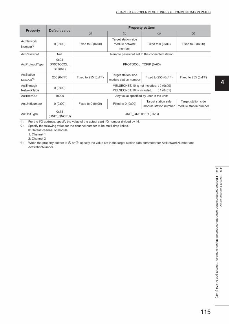
115
CHAPTER 4 PROPERTY SETTINGS OF COMMUNICATION PATHS
4
4.3 Ethernet C
omm
unication
4.3.9 Ethe
rnet comm
unication w
hen the connected station is built-in E
thernet port Q
CP
U (T
CP
)
*1 : For the I/O address, specify the value of the actual start I/O number divided by 16.*2 : Specify the following value for the channel number to be multi-drop linked.
0: Default channel of module1: Channel 12: Channel 2
*3 : When the property pattern is or , specify the value set in the target station side parameter for ActNetworkNumber and ActStationNumber.
ActNetwork
Number*30 (0x00) Fixed to 0 (0x00)
Target station side
module network
number
Fixed to 0 (0x00) Fixed to 0 (0x00)
ActPassword Null Remote password set to the connected station
ActProtocolType
0x04
(PROTOCOL_
SERIAL)
PROTOCOL_TCPIP (0x05)
ActStation
Number*3255 (0xFF) Fixed to 255 (0xFF)
Target station side
module station numberFixed to 255 (0xFF) Fixed to 255 (0xFF)
ActThrough
NetworkType0 (0x00)
MELSECNET/10 is not included. : 0 (0x00)
MELSECNET/10 is included. : 1 (0x01)
ActTimeOut 10000 Any value specified by user in ms units
ActUnitNumber 0 (0x00) Fixed to 0 (0x00) Fixed to 0 (0x00)Target station side
module station number
Target station side
module station number
ActUnitType0x13
(UNIT_QNCPU)UNIT_QNETHER (0x2C)
Property Default valueProperty pattern

116
4.3.10 Ethernet communication when the connected station is built-in Ethernet port QCPU (UDP)
(1) Configuration
(2) Property patterns
Connected
station CPURelayed network
Relayed station CPU
QnUDE(H)
CPURCPU
R motion
CPU*4
CC IE Control
CC IE Field
MELSECNET/H
Ethernet
Serial communication
CC-Link
Connected
station CPU
Relayed network
Relayed station CPU
QnUDE(H)
CPU
QCPU
(Q mode)
C
Controller
module
LCPU QSCPUQ motion
CPUFXCPU
CC IE Control
CC IE Field *1 *2 *1 *1
MELSECNET/H
Ethernet
Serial communication *3
CC-Link
Connected
station CPU
Relayed
module
Relayed network
Relayed
station CPU
Relayed
modulePersonal computer

117
CHAPTER 4 PROPERTY SETTINGS OF COMMUNICATION PATHS
4
4.3 Ethernet C
omm
unication
4.3.10 Eth
ernet comm
unication when the connected station is built-in E
thernet port Q
CP
U (U
DP
)
*1 : Since CC-Link IE Field Network is not supported, R motion CPU, Q12DCCPU-V (Basic mode), QSCPU, and Q motion CPU relayed by CC-Link IE Field Network cannot be accessed.
*2 : Since CC-Link IE Controller Network is not supported, LCPU relayed by CC-Link IE Controller Network cannot be accessed.
*3 : For Redundant CPU, serial communication modules on the main base cannot be accessed.*4 : Only CPU No.2 or later in a multiple CPU configuration can be accessed.*5 : Q24DHCCPU-V and Q24DHCCPU-LS cannot be accessed because the communication route is not supported.*6 : Since C Controller module is not supported by MELSOFT direct connection, Ethernet port direct connection is not
applicable. *7 : For Q172D, Q173D, Q172DS, and Q173DS, only CPU No.2 or later in a multiple CPU configuration can be accessed.
Connected station CPU
Relayed network
Relayed station CPU
C Controller module
RCPUR motion
CPU*4
*4,*5,*6
CC IE ControlCC IE Field
MELSECNET/H
Ethernet
Serial communication
CC-Link
Connected station CPU
Relayed network
Relayed station CPU
C Controller module
QCPU (Q mode)
C Controller
moduleLCPU QSCPU
Q motion CPU
FXCPU
*4,*5,*6
CC IE ControlCC IE Field
*1 *2 *1 *1
MELSECNET/H
Ethernet
Serial communication
CC-Link
Connected station CPU
Relayed network
Relayed station CPU
Q motionCPU
RCPUR motion
CPU
*7
CC IE ControlCC IE Field
MELSECNET/H
Ethernet
Serial communication
CC-Link
Connected station CPU
Relayed network
Relayed station CPU
Q motionCPU
QCPU (Q mode)
C Controller
moduleLCPU QSCPU
Q motion CPU
FXCPU
*7
CC IE ControlCC IE Field
MELSECNET/H
Ethernet
Serial communication
CC-Link
: Accessible (The number in the circle is the property pattern number.), : Inaccessible
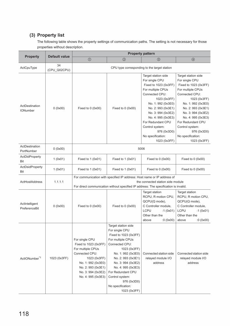
118
(3) Property listThe following table shows the property settings of communication paths. The setting is not necessary for those
properties without description.
Property Default valueProperty pattern
ActCpuType34
(CPU_Q02CPU)CPU type corresponding to the target station
ActDestination
IONumber0 (0x00) Fixed to 0 (0x00) Fixed to 0 (0x00)
Target station side
For single CPU
Fixed to 1023 (0x3FF)
For multiple CPUs
Connected CPU:
1023 (0x3FF)
No. 1: 992 (0x3E0)
No. 2: 993 (0x3E1)
No. 3: 994 (0x3E2)
No. 4: 995 (0x3E3)
For Redundant CPU
Control system:
976 (0x3D0)
No specification:
1023 (0x3FF)
Target station side
For single CPU
Fixed to 1023 (0x3FF)
For multiple CPUs
Connected CPU:
1023 (0x3FF)
No. 1: 992 (0x3E0)
No. 2: 993 (0x3E1)
No. 3: 994 (0x3E2)
No. 4: 995 (0x3E3)
For Redundant CPU
Control system:
976 (0x3D0)
No specification:
1023 (0x3FF)
ActDestination
PortNumber0 (0x00) 5006
ActDidProperty
Bit1 (0x01) Fixed to 1 (0x01) Fixed to 1 (0x01) Fixed to 0 (0x00) Fixed to 0 (0x00)
ActDsidProperty
Bit1 (0x01) Fixed to 1 (0x01) Fixed to 1 (0x01) Fixed to 0 (0x00) Fixed to 0 (0x00)
ActHostAddress 1.1.1.1
For communication with specified IP address: Host name or IP address of
the connected station side module
For direct communication without specified IP address: The specification is invalid.
ActIntelligent
PreferenceBit0 (0x00) Fixed to 0 (0x00) Fixed to 0 (0x00)
Target station
RCPU, R motion CPU,
QCPU(Q mode),
C Controller module,
LCPU :1 (0x01)
Other than the
above :0 (0x00)
Target station
RCPU, R motion CPU,
QCPU(Q mode),
C Controller module,
LCPU :1 (0x01)
Other than the
above :0 (0x00)
ActIONumber*1 1023 (0x3FF)
For single CPU
Fixed to 1023 (0x3FF)
For multiple CPUs
Connected CPU:
1023 (0x3FF)
No. 1: 992 (0x3E0)
No. 2: 993 (0x3E1)
No. 3: 994 (0x3E2)
No. 4: 995 (0x3E3)
Target station side
For single CPU
Fixed to 1023 (0x3FF)
For multiple CPUs
Connected CPU:
1023 (0x3FF)
No. 1: 992 (0x3E0)
No. 2: 993 (0x3E1)
No. 3: 994 (0x3E2)
No. 4: 995 (0x3E3)
For Redundant CPU
Control system:
976 (0x3D0)
No specification:
1023 (0x3FF)
Connected station side
relayed module I/O
address
Connected station side
relayed module I/O
address

119
CHAPTER 4 PROPERTY SETTINGS OF COMMUNICATION PATHS
4
4.3 Ethernet C
omm
unication
4.3.10 Eth
ernet comm
unication when the connected station is built-in E
thernet port Q
CP
U (U
DP
)
*1 : For the I/O address, specify the value of the actual start I/O number divided by 16.*2 : Specify the following value for the channel number to be multi-drop linked.
0: Default channel of module1: Channel 12: Channel 2
*3 : When the property pattern is or , specify the value set in the target station side parameter for ActNetworkNumber and ActStationNumber.
ActMultiDrop
ChannelNumber*20 (0x00) Fixed to 0 (0x00) Fixed to 0 (0x00)
Multi-drop channel
numberFixed to 0 (0x00)
ActNetwork
Number*30 (0x00) Fixed to 0 (0x00)
Target station side
module network
number
Fixed to 0 (0x00) Fixed to 0 (0x00)
ActPassword Null Remote password set to the connected station
ActProtocolType
0x04
(PROTOCOL_
SERIAL)
PROTOCOL_UDPIP (0x08)
ActStation
Number*3255 (0xFF) Fixed to 255 (0xFF)
Target station side
module station numberFixed to 255 (0xFF) Fixed to 255 (0xFF)
ActThrough
NetworkType0 (0x00)
MELSECNET/10 is not included. : 0 (0x00)
MELSECNET/10 is included. : 1 (0x01)
ActTimeOut 10000 Any value specified by user in ms units
ActUnitNumber 0 (0x00) Fixed to 0 (0x00) Fixed to 0 (0x00)Target station side
module station number
Target station side
module station number
ActUnitType0x13
(UNIT_QNCPU)
For communication with specified IP address: UNIT_QNETHER (0x2C)
For direct communication without specified IP address: UNIT_QNETHER_DIRECT (0x2D)
Property Default valueProperty pattern

120
4.3.11 Ethernet communication when the connected station is built-in Ethernet port LCPU (TCP)
(1) Configuration
(2) Property patterns
*1 : Since CC-Link IE Controller Network is not supported, LCPU relayed by CC-Link IE Controller Network cannot be accessed.
*2 : Since CC-Link IE Field Network is not supported, Q12DCCPU-V (Basic mode) relayed by CC-Link IE Field Network cannot be accessed.
*3 : For Redundant CPU, serial communication modules on the main base cannot be accessed.
Connected
station CPURelayed network
Relayed station CPU
LCPU RCPUR motion
CPU
CC IE Field*1
MELSECNET/H
Ethernet
Serial communication
CC-Link
Connected
station CPU
Relayed network
Relayed station CPU
LCPUQCPU
(Q mode)
C
Controller
module
LCPU QSCPUQ motion
CPUFXCPU
CC IE Field*1 *2
MELSECNET/H
Ethernet
Serial communication *3
CC-Link
: Accessible (The number in the circle is the property pattern number.), : Inaccessible
Connected
station CPU
Relayed
module
Relayed network
Relayed
station CPU
Relayed
modulePersonal computer
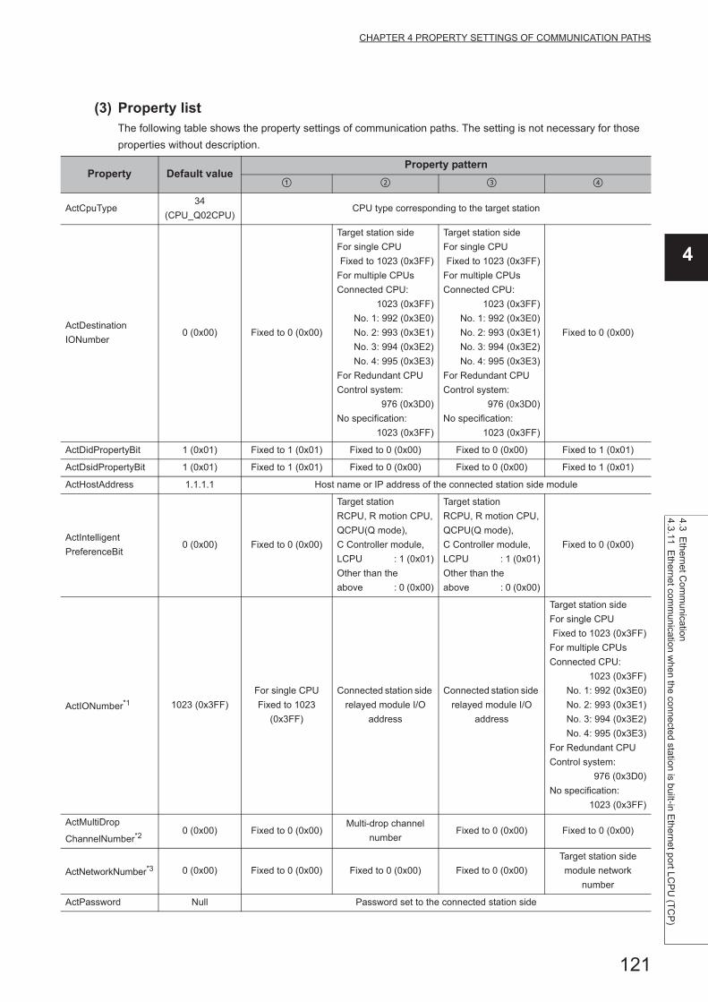
121
CHAPTER 4 PROPERTY SETTINGS OF COMMUNICATION PATHS
4
4.3 Ethernet C
omm
unication
4.3.11 Eth
ernet comm
unication when the connected station is built-in E
thernet port LC
PU
(TC
P)
(3) Property listThe following table shows the property settings of communication paths. The setting is not necessary for those
properties without description.
Property Default valueProperty pattern
ActCpuType34
(CPU_Q02CPU)CPU type corresponding to the target station
ActDestination
IONumber0 (0x00) Fixed to 0 (0x00)
Target station side
For single CPU
Fixed to 1023 (0x3FF)
For multiple CPUs
Connected CPU:
1023 (0x3FF)
No. 1: 992 (0x3E0)
No. 2: 993 (0x3E1)
No. 3: 994 (0x3E2)
No. 4: 995 (0x3E3)
For Redundant CPU
Control system:
976 (0x3D0)
No specification:
1023 (0x3FF)
Target station side
For single CPU
Fixed to 1023 (0x3FF)
For multiple CPUs
Connected CPU:
1023 (0x3FF)
No. 1: 992 (0x3E0)
No. 2: 993 (0x3E1)
No. 3: 994 (0x3E2)
No. 4: 995 (0x3E3)
For Redundant CPU
Control system:
976 (0x3D0)
No specification:
1023 (0x3FF)
Fixed to 0 (0x00)
ActDidPropertyBit 1 (0x01) Fixed to 1 (0x01) Fixed to 0 (0x00) Fixed to 0 (0x00) Fixed to 1 (0x01)
ActDsidPropertyBit 1 (0x01) Fixed to 1 (0x01) Fixed to 0 (0x00) Fixed to 0 (0x00) Fixed to 1 (0x01)
ActHostAddress 1.1.1.1 Host name or IP address of the connected station side module
ActIntelligent
PreferenceBit0 (0x00) Fixed to 0 (0x00)
Target station
RCPU, R motion CPU,
QCPU(Q mode),
C Controller module,
LCPU : 1 (0x01)
Other than the
above : 0 (0x00)
Target station
RCPU, R motion CPU,
QCPU(Q mode),
C Controller module,
LCPU : 1 (0x01)
Other than the
above : 0 (0x00)
Fixed to 0 (0x00)
ActIONumber*1 1023 (0x3FF)
For single CPU
Fixed to 1023
(0x3FF)
Connected station side
relayed module I/O
address
Connected station side
relayed module I/O
address
Target station side
For single CPU
Fixed to 1023 (0x3FF)
For multiple CPUs
Connected CPU:
1023 (0x3FF)
No. 1: 992 (0x3E0)
No. 2: 993 (0x3E1)
No. 3: 994 (0x3E2)
No. 4: 995 (0x3E3)
For Redundant CPU
Control system:
976 (0x3D0)
No specification:
1023 (0x3FF)
ActMultiDrop
ChannelNumber*20 (0x00) Fixed to 0 (0x00)
Multi-drop channel
numberFixed to 0 (0x00) Fixed to 0 (0x00)
ActNetworkNumber*3 0 (0x00) Fixed to 0 (0x00) Fixed to 0 (0x00) Fixed to 0 (0x00)
Target station side
module network
number
ActPassword Null Password set to the connected station side

122
*1 : For the I/O address, specify the value of the actual start I/O number divided by 16.*2 : Specify the following value for the channel number to be multi-drop linked.
0: Default channel of module1: Channel 12: Channel 2
*3 : When the property pattern is or , specify the value set in the target station side parameter for ActNetworkNumber and ActStationNumber.
ActProtocolType
0x04
(PROTOCOL_
SERIAL)
PROTOCOL_TCPIP (0x05)
ActStationNumber*3 255 (0xFF)Fixed to 255
(0xFF)Fixed to 255 (0xFF) Fixed to 255 (0xFF)
Target station side
module station number
ActThroughNetwork
Type0 (0x00)
MELSECNET/10 is not included. : 0 (0x00)
MELSECNET/10 is included. : 1 (0x01)
ActTimeOut 10000 Any value specified by user in ms units.
ActUnitNumber 0 (0x00) Fixed to 0 (0x00)Target station side
module station number
Target station side
module station numberFixed to 0 (0x00)
ActUnitType0x13
(UNIT_QNCPU)UNIT_LNETHER (0x52)
Property Default valueProperty pattern

123
CHAPTER 4 PROPERTY SETTINGS OF COMMUNICATION PATHS
4
4.3 Ethernet C
omm
unication
4.3.12 Eth
ernet comm
unication when the connected station is built-in E
thernet port LC
PU
(UD
P)
4.3.12 Ethernet communication when the connected station is built-in Ethernet port LCPU (UDP)
(1) Configuration
(2) Property patterns
*1 : Since CC-Link IE Controller Network is not supported, LCPU relayed by CC-Link IE Controller Network cannot be accessed.
*2 : Since CC-Link IE Field Network is not supported, Q12DCCPU-V (Basic mode) relayed by CC-Link IE Field Network cannot be accessed.
*3 : For Redundant CPU, serial communication modules on the main base cannot be accessed.
Connected
station CPURelayed network
Relayed station CPU
LCPU RCPUR motion
CPU
CC IE Field*1
MELSECNET/H
Ethernet
Serial communication
CC-Link
Connected
station CPU
Relayed network
Relayed station CPU
LCPUQCPU
(Q mode)
C
Controller
module
LCPU QSCPUQ motion
CPUFXCPU
CC IE Field*1 *2
MELSECNET/H
Ethernet
Serial communication *3
CC-Link
: Accessible (The number in the circle is the property pattern number.), : Inaccessible
Connected
station CPU
Relayed
module
Relayed network
Relayed
station CPU
Relayed
modulePersonal computer

124
(3) Property listThe following table shows the property settings of communication paths. The setting is not necessary for those
properties without description.
Property Default valueProperty pattern
ActCpuType34
(CPU_Q02CPU)CPU type corresponding to the target station
ActDestination
IONumber0 (0x00) Fixed to 0 (0x00)
Target station side
For single CPU
Fixed to 1023 (0x3FF)
For multiple CPUs
Connected CPU:
1023 (0x3FF)
No. 1: 992 (0x3E0)
No. 2: 993 (0x3E1)
No. 3: 994 (0x3E2)
No. 4: 995 (0x3E3)
For Redundant CPU
Control system:
976 (0x3D0)
No specification:
1023 (0x3FF)
Target station side
For single CPU
Fixed to 1023 (0x3FF)
For multiple CPUs
Connected CPU:
1023 (0x3FF)
No. 1: 992 (0x3E0)
No. 2: 993 (0x3E1)
No. 3: 994 (0x3E2)
No. 4: 995 (0x3E3)
For Redundant CPU
Control system:
976 (0x3D0)
No specification:
1023 (0x3FF)
Fixed to 0 (0x00)
ActDidPropertyBit 1 (0x01) Fixed to 1 (0x01) Fixed to 0 (0x00) Fixed to 0 (0x00) Fixed to 1 (0x01)
ActDsidPropertyBit 1 (0x01) Fixed to 1 (0x01) Fixed to 0 (0x00) Fixed to 0 (0x00) Fixed to 1 (0x01)
ActHostAddress 1.1.1.1
For communication with specified IP address: Host name or IP address of
the connected station side module
For direct communication without specified IP address: The specification is invalid.
ActIntelligent
PreferenceBit0 (0x00) Fixed to 0 (0x00)
Target station
RCPU, R motion CPU,
QCPU(Q mode),
C Controller module,
LCPU :1 (0x01)
Other than the
above :0 (0x00)
Target station
RCPU, R motion CPU,
QCPU(Q mode),
C Controller module,
LCPU :1 (0x01)
Other than the
above :0 (0x00)
Fixed to 0 (0x00)
ActIONumber*1 1023 (0x3FF)
For single CPU
Fixed to 1023
(0x3FF)
Connected station side
module I/O address
Connected station side
module I/O address
Target station side
For single CPU
Fixed to 1023 (0x3FF)
For multiple CPUs
Connected CPU:
1023 (0x3FF)
No. 1: 992 (0x3E0)
No. 2: 993 (0x3E1)
No. 3: 994 (0x3E2)
No. 4: 995 (0x3E3)
For Redundant CPU
Control system:
976 (0x3D0)
No specification:
1023 (0x3FF)
ActMultiDrop
ChannelNumber*20 (0x00) Fixed to 0 (0x00)
Multi-drop channel
numberFixed to 0 (0x00) Fixed to 0 (0x00)
ActNetworkNumber*3 0 (0x00) Fixed to 0 (0x00) Fixed to 0 (0x00) Fixed to 0 (0x00)
Target station side
module network
number

125
CHAPTER 4 PROPERTY SETTINGS OF COMMUNICATION PATHS
4
4.3 Ethernet C
omm
unication
4.3.12 Eth
ernet comm
unication when the connected station is built-in E
thernet port LC
PU
(UD
P)
*1 : For the I/O address, specify the value of the actual start I/O number divided by 16.*2 : Specify the following value for the channel number to be multi-drop linked.
0: Default channel of module1: Channel 12: Channel 2
*3 : When the property pattern is or , specify the value set in the target station side parameter for ActNetworkNumber and ActStationNumber.
ActPassword Null Remote password set to the connected station
ActProtocolType
0x04
(PROTOCOL_
SERIAL)
PROTOCOL_UDPIP (0x08)
ActStationNumber*3 255 (0xFF)Fixed to 255
(0xFF)Fixed to 255 (0xFF) Fixed to 255 (0xFF)
Target station side
module station number
ActThroughNetwork
Type0 (0x00)
MELSECNET/10 is not included. : 0 (0x00)
MELSECNET/10 is included. : 1 (0x01)
ActTimeOut 10000 Any value specified by user in ms units
ActUnitNumber 0 (0x00) Fixed to 0 (0x00)Target station side
module station number
Target station side
module station numberFixed to 0 (0x00)
ActUnitType0x13
(UNIT_QNCPU)
For communication with specified IP address: UNIT_LNETHER(0x52)
For direct communication without specified IP address: UNIT_LNETHER_DIRECT(0x53)
Property Default valueProperty pattern

126
4.3.13 Ethernet communication when the connected station is Ethernet adapter module (TCP)
(1) Configuration
(2) Property patterns
Connected
station CPURelayed network
Relayed station CPU
QnUDE(H)
CPURCPU
R motion
CPU
CC IE Control
CC IE Field
MELSECNET/H
Ethernet
Serial communication
CC-Link
Connected
station CPU
Relayed network
Relayed station CPU
QnUDE(H)
CPU
QCPU
(Q mode)
C
Controller
module
LCPU QSCPUQ motion
CPUFXCPU
CC IE Control
CC IE Field *1 *2
MELSECNET/H
Ethernet
Serial communication
CC-Link
Connected
station CPU
CC-Link IE Field
Network module
Relayed
module
Relayed network
Relayed
station CPURelayed
modulePersonal computer
Ethernet adapter module

127
CHAPTER 4 PROPERTY SETTINGS OF COMMUNICATION PATHS
4
4.3 Ethernet C
omm
unication
4.3.13 Eth
ernet comm
unication when the connected station is E
thernet adapter module (T
CP
)
*1 : Since CC-Link IE Field Network is not supported, Q12DCCPU-V (Basic mode) relayed by CC-Link IE Field Network cannot be accessed.
*2 : Since CC-Link IE Controller Network is not supported, LCPU relayed by CC-Link IE Controller Network cannot be accessed.
Connected
station CPURelayed network
Relayed station CPU
LCPU RCPUR motion
CPU
CC IE Field*2
MELSECNET/H
Ethernet
Serial communication
CC-Link
Connected
station CPU
Relayed network
Relayed station CPU
LCPUQCPU
(Q mode)
C
Controller
module
LCPU QSCPUQ motion
CPUFXCPU
CC IE Field*2 *1
MELSECNET/H
Ethernet
Serial communication
CC-Link
: Accessible (The number in the circle is the property pattern number.), : Inaccessible

128
(3) Property listThe following table shows the property settings of communication paths. The setting is not necessary for those
properties without description.
Property Default valueProperty pattern
ActCpuType34
(CPU_Q02CPU)CPU type corresponding to the target station
ActDestination
IONumber0 (0x00) Fixed to 0 (0x00) Fixed to 0 (0x00)
Target station side
For single CPU
Fixed to 1023 (0x3FF)
For multiple CPUs
Connected CPU:
1023 (0x3FF)
No. 1: 992 (0x3E0)
No. 2: 993 (0x3E1)
No. 3: 994 (0x3E2)
No. 4: 995 (0x3E3)
For Redundant CPU
Control system:
976 (0x3D0)
No specification:
1023 (0x3FF)
Target station side
For single CPU
Fixed to 1023 (0x3FF)
For multiple CPUs
Connected CPU:
1023 (0x3FF)
No. 1: 992 (0x3E0)
No. 2: 993 (0x3E1)
No. 3: 994 (0x3E2)
No. 4: 995 (0x3E3)
For Redundant CPU
Control system:
976 (0x3D0)
No specification:
1023 (0x3FF)
ActDidProperty
Bit1 (0x01) Fixed to 1 (0x01) Fixed to 1 (0x01) Fixed to 0 (0x00) Fixed to 0 (0x00)
ActDsidProperty
Bit1 (0x01) Fixed to 1 (0x01) Fixed to 1 (0x01) Fixed to 0 (0x00) Fixed to 0 (0x00)
ActHostAddress 1.1.1.1 Host name or IP address of the Ethernet adapter module
ActIntelligent
PreferenceBit0 (0x00) Fixed to 0 (0x00)
ActIONumber*1 1023 (0x3FF)
Target station side
For single CPU
Fixed to 1023 (0x3FF)
For multiple CPUs
Connected CPU:
1023 (0x3FF)
No. 1: 992 (0x3E0)
No. 2: 993 (0x3E1)
No. 3: 994 (0x3E2)
No. 4: 995 (0x3E3)
Target station side
For single CPU
Fixed to 1023 (0x3FF)
For multiple CPUs
Connected CPU:
1023 (0x3FF)
No. 1: 992 (0x3E0)
No. 2: 993 (0x3E1)
No. 3: 994 (0x3E2)
No. 4: 995 (0x3E3)
For Redundant CPU
Control system:
976 (0x3D0)
No specification:
1023 (0x3FF)
Connected station side
relayed module I/O
address
Connected station side
relayed module I/O
address
ActMultiDrop
ChannelNumber*20 (0x00) Fixed to 0 (0x00) Fixed to 0 (0x00)
Multi-drop channel
numberFixed to 0 (0x00)
ActNetwork
Number*30 (0x00)
Connected station side
CC-Link IE Field
Network module
station number
Target station side
module network
number
Connected station side
CC-Link IE Field
Network module
station number
Connected station side
CC-Link IE Field
Network module
station number
ActProtocolType
0x04
(PROTOCOL_
SERIAL)
PROTOCOL_TCPIP (0x05)

129
CHAPTER 4 PROPERTY SETTINGS OF COMMUNICATION PATHS
4
4.3 Ethernet C
omm
unication
4.3.13 Eth
ernet comm
unication when the connected station is E
thernet adapter module (T
CP
)
*1 : For the I/O address, specify the value of the actual start I/O number divided by 16.*2 : Specify the following value for the channel number to be multi-drop linked.
0: Default channel of module1: Channel 12: Channel 2
*3 : When the property pattern is , , or , specify the parameter value set for the CC-Link IE Field Network module on the connected station side for ActNetworkNumber and ActStationNumber. When the property pattern is , specify the value set in the target station side parameter for ActNetworkNumber and ActStationNumber.
ActStation
Number*3255 (0xFF)
Connected station side
CC-Link IE Field
Network module
station number
Target station side
module station number
Connected station side
CC-Link IE Field
Network module
station number
Connected station side
CC-Link IE Field
Network module
station number
ActThrough
NetworkType0 (0x00)
MELSECNET/10 is not included. : 0 (0x00)
MELSECNET/10 is included. : 1 (0x01)
ActTimeOut 10000 Any value specified by user in ms units
ActUnitNumber 0 (0x00) Fixed to 0 (0x00) Fixed to 0 (0x00)Target station side
module station number
Target station side
module station number
ActUnitType0x13
(UNIT_QNCPU)UNIT_NZ2GF_ETB (0x59)
Property Default valueProperty pattern

130
4.3.14 Ethernet communication when the connected station is Ethernet adapter module (UDP)
(1) Configuration
(2) Property patterns
Connected
station CPURelayed network
Relayed station CPU
QnUDE(H)
CPURCPU
R motion
CPU
CC IE Control
CC IE Field
MELSECNET/H
Ethernet
Serial communication
CC-Link
Connected
station CPU
Relayed network
Relayed station CPU
QnUDE(H)
CPU
QCPU
(Q mode)
C
Controller
module
LCPU QSCPUQ motion
CPUFXCPU
CC IE Control
CC IE Field *1 *2
MELSECNET/H
Ethernet
Serial communication
CC-Link
Connected
station CPU
CC-Link IE Field
Network module
Relayed
module
Relayed network
Relayed
station CPURelayed
modulePersonal computer
Ethernet adapter module

131
CHAPTER 4 PROPERTY SETTINGS OF COMMUNICATION PATHS
4
4.3 Ethernet C
omm
unication
4.3.14 Eth
ernet comm
unication when the connected station is E
thernet adapter module (U
DP
)
*1 : Since CC-Link IE Field Network is not supported, Q12DCCPU-V (Basic mode) relayed by CC-Link IE Field Network cannot be accessed.
*2 : Since CC-Link IE Controller Network is not supported, LCPU relayed by CC-Link IE Controller Network cannot be accessed.
Connected
station CPURelayed network
Relayed station CPU
LCPU RCPUR motion
CPU
CC IE Field*2
MELSECNET/H
Ethernet
Serial communication
CC-Link
Connected
station CPU
Relayed network
Relayed station CPU
LCPUQCPU
(Q mode)
C
Controller
module
LCPU QSCPUQ motion
CPUFXCPU
CC IE Field*2 *1
MELSECNET/H
Ethernet
Serial communication
CC-Link
: Accessible (The number in the circle is the property pattern number.), : Inaccessible

132
(3) Property listThe following table shows the property settings of communication paths. The setting is not necessary for those
properties without description.
Property Default valueProperty pattern
ActCpuType34
(CPU_Q02CPU)CPU type corresponding to the target station
ActDestination
IONumber0 (0x00) Fixed to 0 (0x00) Fixed to 0 (0x00)
Target station side
For single CPU
Fixed to 1023 (0x3FF)
For multiple CPUs
Connected CPU:
1023 (0x3FF)
No. 1: 992 (0x3E0)
No. 2: 993 (0x3E1)
No. 3: 994 (0x3E2)
No. 4: 995 (0x3E3)
For Redundant CPU
Control system:
976 (0x3D0)
No specification:
1023 (0x3FF)
Target station side
For single CPU
Fixed to 1023 (0x3FF)
For multiple CPUs
Connected CPU:
1023 (0x3FF)
No. 1: 992 (0x3E0)
No. 2: 993 (0x3E1)
No. 3: 994 (0x3E2)
No. 4: 995 (0x3E3)
For Redundant CPU
Control system:
976 (0x3D0)
No specification:
1023 (0x3FF)
ActDidProperty
Bit1 (0x01) Fixed to 1 (0x01) Fixed to 1 (0x01) Fixed to 0 (0x00) Fixed to 0 (0x00)
ActDsidProperty
Bit1 (0x01) Fixed to 1 (0x01) Fixed to 1 (0x01) Fixed to 0 (0x00) Fixed to 0 (0x00)
ActHostAddress 1.1.1.1For communication with specified IP address: Host name or IP address of the Ethernet adapter module
For direct communication without specified IP address: The specification is invalid.
ActIntelligent
PreferenceBit0 (0x00) Fixed to 0 (0x00)
ActIONumber*1 1023 (0x3FF)
For single CPU
Fixed to 1023 (0x3FF)
For multiple CPUs
Connected CPU:
1023 (0x3FF)
No. 1: 992 (0x3E0)
No. 2: 993 (0x3E1)
No. 3: 994 (0x3E2)
No. 4: 995 (0x3E3)
Target station side
For single CPU
Fixed to 1023 (0x3FF)
For multiple CPUs
Connected CPU:
1023 (0x3FF)
No. 1: 992 (0x3E0)
No. 2: 993 (0x3E1)
No. 3: 994 (0x3E2)
No. 4: 995 (0x3E3)
For Redundant CPU
Control system:
976 (0x3D0)
No specification:
1023 (0x3FF)
Connected station side
relayed module I/O
address
Connected station side
relayed module I/O
address
ActMultiDrop
ChannelNumber*20 (0x00) Fixed to 0 (0x00) Fixed to 0 (0x00)
Multi-drop channel
numberFixed to 0 (0x00)
ActNetwork
Number*30 (0x00)
Connected station side
CC-Link IE Field
Network module
station number
Target station side
module station number
Connected station side
CC-Link IE Field
Network module
station number
Connected station side
CC-Link IE Field
Network module
station number

133
CHAPTER 4 PROPERTY SETTINGS OF COMMUNICATION PATHS
4
4.3 Ethernet C
omm
unication
4.3.14 Eth
ernet comm
unication when the connected station is E
thernet adapter module (U
DP
)
*1 : For the I/O address, specify the value of the actual start I/O number divided by 16.*2 : Specify the following value for the channel number to be multi-drop linked.
0: Default channel of module1: Channel 12: Channel 2
*3 : When the property pattern is , , or , specify the parameter value set for the CC-Link IE Field Network module on the connected station side for ActNetworkNumber and ActStationNumber. When the property pattern is , specify the value set in the target station side parameter for ActNetworkNumber and ActStationNumber.
ActProtocolType
0x04
(PROTOCOL_
SERIAL)
PROTOCOL_UDPIP (0x08)
ActStation
Number*3255 (0xFF)
Connected station side
CC-Link IE Field
Network module
station number
Target station side
module station number
Connected station side
CC-Link IE Field
Network module
station number
Connected station side
CC-Link IE Field
Network module
station number
ActThrough
NetworkType0 (0x00)
MELSECNET/10 is not included. : 0 (0x00)
MELSECNET/10 is included. : 1 (0x01)
ActTimeOut 10000 Any value specified by user in ms units
ActUnitNumber 0 (0x00) Fixed to 0 (0x00) Fixed to 0 (0x00)Target station side
module station number
Target station side
module station number
ActUnitType0x13
(UNIT_QNCPU)
For communication with specified IP address: UNIT_NZ2GF_ETB (0x59)
For direct communication without specified IP address: UNIT_NZ2GF_ETB_DIRECT (0x5A)
Property Default valueProperty pattern

134
4.3.15 Ethernet communication when the connected station is Ethernet adapter (TCP)
(1) Configuration
(2) Property patterns
*1 : Only FX3SCPU, FX3G(C)CPU and FX3U(C)CPU can be accessed.
Connected
station CPURelayed network
Relayed station CPU
FXCPU RCPUR motion
CPU
*1
CC IE Control
CC IE Field
MELSECNET/H
Ethernet
Serial communication
CC-Link
Connected
station CPU
Relayed network
Relayed station CPU
FXCPUQCPU
(Q mode)
C
Controller
module
LCPU QSCPUQ motion
CPUFXCPU
*1
CC IE Control
CC IE Field
MELSECNET/H
Ethernet
Serial communication
CC-Link
: Accessible (The number in the circle is the property pattern number.), : Inaccessible
Ethernet
adapter
Personal computer
Connected
station CPU
Relayed
module
Relayed network
Relayed
station CPU
Relayed
module

135
CHAPTER 4 PROPERTY SETTINGS OF COMMUNICATION PATHS
4
4.3 Ethernet C
omm
unication
4.3.15 Eth
ernet comm
unication when the connected station is E
thernet adapter (TC
P)
(3) Property listThe following table shows the property settings of communication paths. The setting is not necessary for those
properties without description.
Property Default valueProperty pattern
ActCpuType34
(CPU_Q02CPU)CPU type corresponding to the target station
ActHostAddress 1.1.1.1 Host name or IP address of the connected station side module
ActProtocolType0x04
(PROTOCOL_SERIAL)PROTOCOL_TCPIP
ActTimeOut 10000 Any value specified by user in ms units
ActUnitType 0x13 (UNIT_QNCPU) UNIT_FXETHER

136
4.3.16 Ethernet communication when the connected station is Ethernet adapter (UDP)
(1) Configuration
(2) Property patterns
*1 : Only FX3SCPU, FX3G(C)CPU and FX3U(C)CPU can be accessed.
(3) Property listThe following table shows the property settings of communication paths. The setting is not necessary for those
properties without description.
Connected station CPU
Relayed network
Relayed station CPU
FXCPU RCPUR motion
CPU
*1
CC IE Control
CC IE Field
MELSECNET/H
Ethernet
Serial communication
CC-Link
Connected station CPU
Relayed network
Relayed station CPU
FXCPUQCPU
(Q mode)
C Controller
moduleLCPU QSCPU
Q motion CPU
FXCPU
*1
CC IE Control
CC IE Field
MELSECNET/H
Ethernet
Serial communication
CC-Link
: Accessible (The number in the circle is the property pattern number.), : Inaccessible
Property Default valueProperty pattern
ActCpuType34
(CPU_Q02CPU)CPU type corresponding to the target station
ActProtocolType0x04
(PROTOCOL_SERIAL)PROTOCOL_UDPIP
ActTimeOut 10000 Any value specified by user in ms units
ActUnitType 0x13 (UNIT_QNCPU) UNIT_FXETHER_DIRECT
Ethernet
adapter
Personal computer
Connected
station CPU
Relayed
module
Relayed network
Relayed
station CPU
Relayed
module

137
CHAPTER 4 PROPERTY SETTINGS OF COMMUNICATION PATHS
4
4.3 Ethernet C
omm
unication
4.3.17 Eth
ernet comm
unication when the connected station is robot controlle
r
4.3.17 Ethernet communication when the connected station is robot controller
(1) Configuration
(2) Property listThe following table shows the property settings of communication paths. The setting is not necessary for those
properties without description.
When robot controller communication, the program setting type control cannot be used.Use the utility setting type control.
Property Default valueProperty pattern
ActProtocolType0x04
(PROTOCOL_SERIAL)RC_PROTOCOL_TCPIP(0x02)
ActCpuType34
(CPU_Q02CPU)Robot controller type(0x013001)
ActPortNumber 1(PORT_1) Port number to be connected (specify 10001 normally)
ActHostAddress 1.1.1.1 Host name or IP address of the connected station side robot controller
ActTimeOut 10000 Any value specified by user in ms units.
ActCpuTimeOut 0(0x00) Any value specified by user in 10ms units.
ActMultiDropChanne
lNumber8(TRC_DTR_OR_RTS) Retry count
ActMxUnitSeries 0(0x00) 2(0x02)
Personal computer
Robot controller

138
4.4 COM Communication
4.4.1 CPU COM communication when the connected station is FX5CPU
(1) Configuration
(2) Property patterns
Connected
station CPURelayed network
Relayed station CPU
FX5CPU RCPUR motion
CPU
CC IE Control
CC IE Field
MELSECNET/H
Ethernet
Serial communication
CC-Link
Connected
station CPU
Relayed network
Relayed station CPU
FX5CPUQCPU
(Q mode)
C
Controller
module
LCPU QSCPUQ motion
CPUFXCPU
CC IE Control
CC IE Field
MELSECNET/H
Ethernet
Serial communication
CC-Link
: Accessible (The number in the circle is the property pattern number.), : Inaccessible
Personal computer
Connected
station CPU
Relayed
station CPU
Relayed
module
Relayed network
Relayed
module

139
CHAPTER 4 PROPERTY SETTINGS OF COMMUNICATION PATHS
4
4.4 CO
M C
om
munication
4.4.1 CP
U C
OM
com
munication w
hen the connecte
d station is FX
5CP
U
(3) Property listThe following table shows the property settings of communication paths. The setting is not necessary for those
properties without description.
Property Default valueProperty pattern
ActBaudRate19200
(BAUDRATE_19200)
BAUDRATE_9600,
BAUDRATE_19200,
BAUDRATE_38400,
BAUDRATE_57600,
BAUDRATE_115200
ActControl 8 (TRC_DTR_OR_RTS) Depending on the used cable.
ActCpuType 34 (CPU_Q02CPU)CPU type corresponding to the
target station
ActDidPropertyBit 1 (0x01) 0 (0x00)
ActDsidPropertyBit 1 (0x01) 0 (0x00)
ActPortNumber 1 (PORT_1)Personal computer side COM
port number
ActProtocolType0x04
(PROTOCOL_SERIAL)PROTOCOL_SERIAL(0x04)
ActHostAddress 1.1.1.1 NULL
ActTimeOut 10000Any value specified by user in ms
units.
ActUnitType 0x13 (UNIT_QNCPU) UNIT_FXVCPU(0x2000)
ActConnectWay TEL_AUTO_CONNECT 0
ActLineType LINETYPE_TONE 0
ActConnectionCDWaitTime 90 0
ActConnectionModemReportWaitTime 5 0
ActDisconnectionCDWaitTime 5 0
ActDisconnectionDelayTime 3 0
ActTransmissionDelayTime 0 0
ActATCommandResponsceWaitTime 1 0
ActPasswordCancelResponseWaitTime 5 0
ActATCommandPasswordCancelRetryTimes 3 0
ActCallbackCancelWaitTime 90 0
ActCallbackDelayTime 20 0
ActCallbackReceptionWaitingTimeOut 120 0

140
4.4.2 CPU COM communication when the connected station is QCPU (Q mode)
(1) Configuration
(2) Property patterns
*1 : Since CC-Link IE Field Network is not supported, R motion CPU, Q12DCCPU-V (Basic mode), QSCPU, and Q motion CPU relayed by CC-Link IE Field Network cannot be accessed.
*2 : Since CC-Link IE Controller Network is not supported, LCPU relayed by CC-Link IE Controller Network cannot be accessed.*3 : For Redundant CPU, serial communication modules on the main base cannot be accessed.*4 : Supported by FX3G(C)CPU and FX3U(C)CPU within the own network only.*5 : Only CPU No.2 or later in a multiple CPU configuration can be accessed.
Connected station CPU
Relayed network
Relayed station CPU
QCPU
(Q mode)
C Controller
moduleRCPU
R motion
CPU
*5
CC IE Control
CC IE Field
MELSECNET/H
Ethernet
Serial communication
CC-Link
Connected station CPU
Relayed network
Relayed station CPU
QCPU
(Q mode)
C Controller
module
QCPU
(Q mode)
C
Controller
module
LCPU QSCPUQ motion
CPUFXCPU
*5
CC IE Control
CC IE Field *1 *2 *1 *1
MELSECNET/H
Ethernet
Serial communication *3
CC-Link *4
: Accessible (The number in the circle is the property pattern number.), : Inaccessible
Personal computer
Connected
station CPU
Relayed
station CPU
Relayed
module
Relayed network
Relayed
module

141
CHAPTER 4 PROPERTY SETTINGS OF COMMUNICATION PATHS
4
4.4 CO
M C
om
munication
4.4.2 CP
U C
OM
com
munication w
hen the con
nected station is Q
CP
U (Q
mode)
(3) Property listThe following table shows the property settings of communication paths. The setting is not necessary for those
properties without description.
Property Default valueProperty pattern
*1
ActBaudRate
19200
(BAUDRATE_
19200)
BAUDRATE_9600, BAUDRATE_19200, BAUDRATE_38400, BAUDRATE_57600,
BAUDRATE_115200
ActControl
8
(TRC_DTR_OR_
RTS)
Depending on the used cable.
ActCpuType34
(CPU_Q02CPU)CPU type corresponding to the target station
ActDestination
IONumber0 (0x00) Fixed to 0 (0x00) Fixed to 0 (0x00)
Target station side
For single CPU
Fixed to 1023 (0x3FF)
For multiple CPUs
Connected CPU:
1023 (0x3FF)
No. 1: 992 (0x3E0)
No. 2: 993 (0x3E1)
No. 3: 994 (0x3E2)
No. 4: 995 (0x3E3)
For Redundant CPU
Control system:
976 (0x3D0)
No specification:
1023 (0x3FF)
Target station side
For single CPU
Fixed to 1023 (0x3FF)
For multiple CPUs
Connected CPU:
1023 (0x3FF)
No. 1: 992 (0x3E0)
No. 2: 993 (0x3E1)
No. 3: 994 (0x3E2)
No. 4: 995 (0x3E3)
For Redundant CPU
Control system:
976 (0x3D0)
No specification:
1023 (0x3FF)
ActDidProperty
Bit1 (0x01) Fixed to 1 (0x01) Fixed to 1 (0x01) Fixed to 0 (0x00) Fixed to 0 (0x00)
ActDsidProperty
Bit1 (0x01) Fixed to 1 (0x01) Fixed to 1 (0x01) Fixed to 0 (0x00) Fixed to 0 (0x00)
ActIntelligent
PreferenceBit0 (0x00) Fixed to 0 (0x00) Fixed to 0 (0x00)
Target station
Q mode,
C Controller module,
LCPU :1 (0x01)
Other than the
above :0 (0x00)
Target station
Q mode,
C Controller module,
LCPU :1 (0x01)
Other than the
above :0 (0x00)
ActIONumber*2 1023 (0x3FF)
Target station side
For single CPU
Fixed to 1023 (0x3FF)
For multiple CPUs
Connected CPU:
1023 (0x3FF)
No. 1: 992 (0x3E0)
No. 2: 993 (0x3E1)
No. 3: 994 (0x3E2)
No. 4: 995 (0x3E3)
For Redundant CPU
Control system:
976 (0x3D0)
No specification:
1023 (0x3FF)
Target station side
For single CPU
Fixed to 1023 (0x3FF)
For multiple CPUs
Connected CPU:
1023 (0x3FF)
No. 1: 992 (0x3E0)
No. 2: 993 (0x3E1)
No. 3: 994 (0x3E2)
No. 4: 995 (0x3E3)
For Redundant CPU
Control system:
976 (0x3D0)
No specification:
1023 (0x3FF)
Connected station side
module I/O address
Connected station side
module I/O address

142
*1 : Note the following considerations when accessing via Ethernet module (Q series-compatible E71). • For ActNetworkNumber and ActStationNumber, specify the value set in the parameter setting of the target station side Q series-
compatible E71. • Set "Station No. IP information" in the parameter setting of Q series-compatible E71. When setting the parameter, specify the
setting other than the automatic response system (any of the IP address calculation system, table conversion system, and combined system) for "Station No. IP information system".
*2 : For the I/O address, specify the value of the actual start I/O number divided by 16.*3 : Specify the following value for the channel number to be multi-drop linked.
0: Default channel of module1: Channel 12: Channel 2
ActMultiDrop
ChannelNumber*30 (0x00) Fixed to 0 (0x00) Fixed to 0 (0x00)
Multi-drop channel
numberFixed to 0 (0x00)
ActNetwork
Number0 (0x00) Fixed to 0 (0x00)
Target station side
module network
number
Fixed to 0 (0x00) Fixed to 0 (0x00)
ActPortNumber 1 (PORT_1) Personal computer side COM port number
ActProtocolType
0x04
(PROTOCOL_
SERIAL)
PROTOCOL_SERIAL (0x04)
ActStation
Number255 (0xFF) Fixed to 255 (0xFF)
Target station side
module station numberFixed to 255 (0xFF) Fixed to 255 (0xFF)
ActThrough
NetworkType0 (0x00)
MELSECNET/10 is not included. : 0 (0x00)
MELSECNET/10 is included. : 1 (0x01)
ActTimeOut 10000 Any value specified by user in ms units.
ActUnitNumber 0 (0x00) Fixed to 0 (0x00) Fixed to 0 (0x00)Target station side
module station number
Target station side
module station number
ActUnitType0x13
(UNIT_QNCPU)UNIT_QNCPU (0x13)
Property Default valueProperty pattern
*1
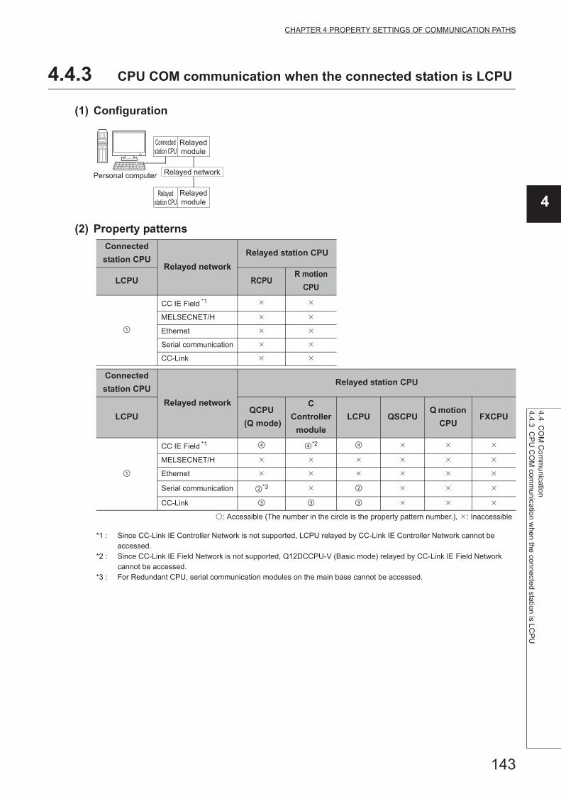
143
CHAPTER 4 PROPERTY SETTINGS OF COMMUNICATION PATHS
4
4.4 CO
M C
om
munication
4.4.3 CP
U C
OM
com
munication w
hen the connecte
d station is LCP
U
4.4.3 CPU COM communication when the connected station is LCPU
(1) Configuration
(2) Property patterns
*1 : Since CC-Link IE Controller Network is not supported, LCPU relayed by CC-Link IE Controller Network cannot be accessed.
*2 : Since CC-Link IE Field Network is not supported, Q12DCCPU-V (Basic mode) relayed by CC-Link IE Field Network cannot be accessed.
*3 : For Redundant CPU, serial communication modules on the main base cannot be accessed.
Connected
station CPURelayed network
Relayed station CPU
LCPU RCPUR motion
CPU
CC IE Field *1
MELSECNET/H
Ethernet
Serial communication
CC-Link
Connected
station CPU
Relayed network
Relayed station CPU
LCPUQCPU
(Q mode)
C
Controller
module
LCPU QSCPUQ motion
CPUFXCPU
CC IE Field *1 *2
MELSECNET/H
Ethernet
Serial communication *3
CC-Link
: Accessible (The number in the circle is the property pattern number.), : Inaccessible
Personal computer
Connected
station CPU
Relayed
station CPU
Relayed
module
Relayed network
Relayed
module

144
(3) Property listThe following table shows the property settings of communication paths. The setting is not necessary for those
properties without description.
Property Default valueProperty pattern
ActBaudRate
19200
(BAUDRATE_
19200)
BAUDRATE_9600, BAUDRATE_19200, BAUDRATE_38400, BAUDRATE_57600,
BAUDRATE_115200
ActControl
8
(TRC_DTR_OR_
RTS)
Depending on the used cable.
ActCpuType34
(CPU_Q02CPU)CPU type corresponding to the target station
ActDestination
IONumber0 (0x00) Fixed to 0 (0x00)
Target station side
For single CPU
Fixed to 1023 (0x3FF)
For multiple CPUs
Connected CPU:
1023 (0x3FF)
No. 1: 992 (0x3E0)
No. 2: 993 (0x3E1)
No. 3: 994 (0x3E2)
No. 4: 995 (0x3E3)
For Redundant CPU
Control system:
976 (0x3D0)
No specification:
1023 (0x3FF)
Target station side
For single CPU
Fixed to 1023 (0x3FF)
For multiple CPUs
Connected CPU:
1023 (0x3FF)
No. 1: 992 (0x3E0)
No. 2: 993 (0x3E1)
No. 3: 994 (0x3E2)
No. 4: 995 (0x3E3)
For Redundant CPU
Control system:
976 (0x3D0)
No specification:
1023 (0x3FF)
Fixed to 0 (0x00)
ActDidPropertyBit 1 (0x01) Fixed to 1 (0x01) Fixed to 0 (0x00) Fixed to 0 (0x00) Fixed to 1 (0x01)
ActDsidPropertyBit 1 (0x01) Fixed to 1 (0x01) Fixed to 0 (0x00) Fixed to 0 (0x00) Fixed to 1 (0x01)
ActIntelligent
PreferenceBit0 (0x00) Fixed to 0 (0x00)
Target station
Q mode,
C Controller module,
LCPU :1 (0x01)
Other than the
above :0 (0x00)
Target station
Q mode,
C Controller module,
LCPU :1 (0x01)
Other than the
above :0 (0x00)
Fixed to 0 (0x00)
ActIONumber*1 1023 (0x3FF)Fixed to 1023
(0x3FF)
Connected station side
module I/O address
Connected station side
module I/O address
Target station side
For single CPU
Fixed to 1023 (0x3FF)
For multiple CPUs
Connected CPU:
1023 (0x3FF)
No. 1: 992 (0x3E0)
No. 2: 993 (0x3E1)
No. 3: 994 (0x3E2)
No. 4: 995 (0x3E3)
For Redundant CPU
Control system:
976 (0x3D0)
No specification:
1023 (0x3FF)
ActMultiDrop
ChannelNumber*20 (0x00) Fixed to 0 (0x00)

145
CHAPTER 4 PROPERTY SETTINGS OF COMMUNICATION PATHS
4
4.4 CO
M C
om
munication
4.4.3 CP
U C
OM
com
munication w
hen the connecte
d station is LCP
U
*1 : For the I/O address, specify the value of the actual start I/O number divided by 16.*2 : Specify the following value for the channel number to be multi-drop linked.
0: Default channel of module1: Channel 12: Channel 2
ActNetworkNumber 0 (0x00) Fixed to 0 (0x00) Fixed to 0 (0x00) Fixed to 0 (0x00)
Target station side
module network
number
ActPortNumber 1 (PORT_1) Personal computer side COM port number
ActProtocolType
0x04
(PROTOCOL_
SERIAL)
PROTOCOL_SERIAL (0x04)
ActStationNumber 255 (0xFF)Fixed to 255
(0xFF)Fixed to 255 (0xFF) Fixed to 255 (0xFF)
Target station side
module station number
ActThroughNetwork
Type0 (0x00)
MELSECNET/10 is not included. : 0 (0x00)
MELSECNET/10 is included. : 1 (0x01)
ActTimeOut 10000 Any value specified by user in ms units.
ActUnitNumber 0 (0x00) Fixed to 0 (0x00)Target station side
module station number
Target station side
module station numberFixed to 0 (0x00)
ActUnitType0x13
(UNIT_QNCPU)UNIT_LNCPU (0x50)
Property Default valueProperty pattern
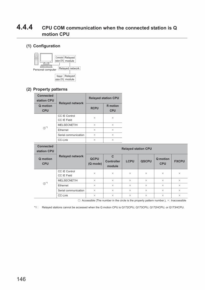
146
4.4.4 CPU COM communication when the connected station is Q motion CPU
(1) Configuration
(2) Property patterns
*1 : Relayed stations cannot be accessed when the Q motion CPU is Q172CPU, Q173CPU, Q172HCPU, or Q173HCPU.
Connected
station CPURelayed network
Relayed station CPU
Q motion
CPURCPU
R motion
CPU
*1
CC IE Control
CC IE Field
MELSECNET/H
Ethernet
Serial communication
CC-Link
Connected
station CPU
Relayed network
Relayed station CPU
Q motion
CPU
QCPU
(Q mode)
C
Controller
module
LCPU QSCPUQ motion
CPUFXCPU
*1
CC IE Control
CC IE Field
MELSECNET/H
Ethernet
Serial communication
CC-Link
: Accessible (The number in the circle is the property pattern number.), : Inaccessible
Personal computer
Connected
station CPU
Relayed
station CPU
Relayed
module
Relayed network
Relayed
module
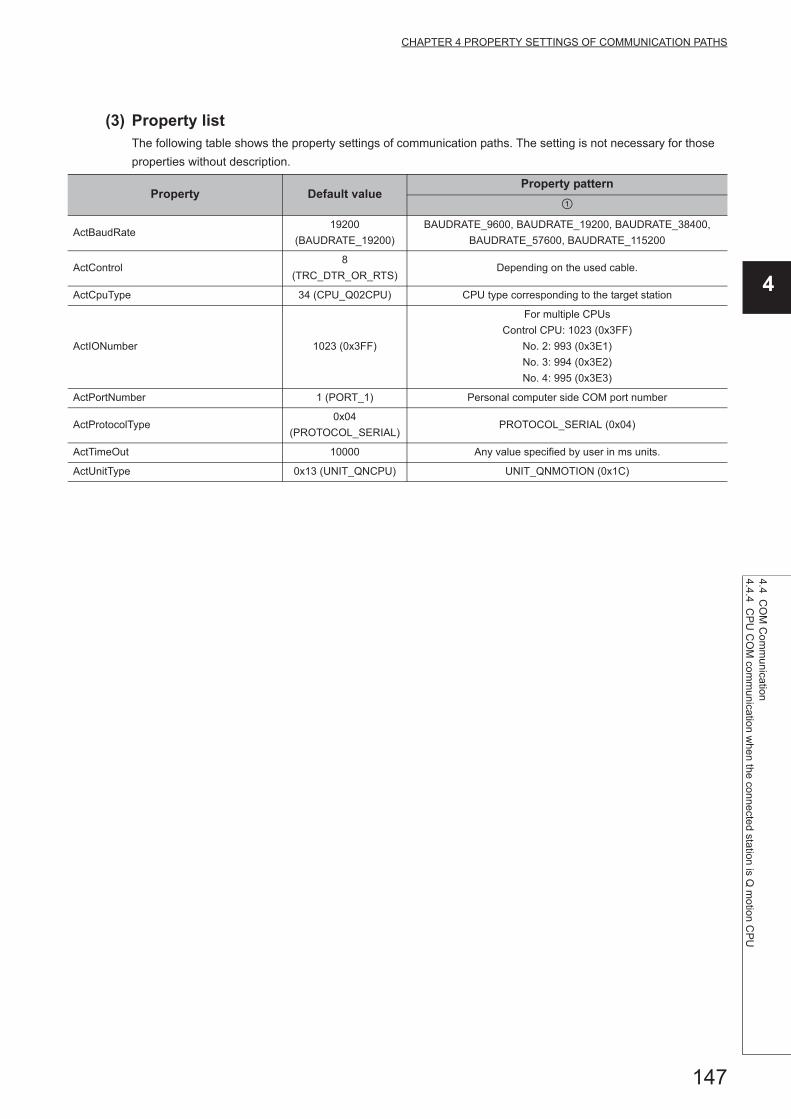
147
CHAPTER 4 PROPERTY SETTINGS OF COMMUNICATION PATHS
4
4.4 CO
M C
om
munication
4.4.4 CP
U C
OM
com
munication w
hen the con
nected station is Q
motion C
PU
(3) Property listThe following table shows the property settings of communication paths. The setting is not necessary for those
properties without description.
Property Default valueProperty pattern
ActBaudRate19200
(BAUDRATE_19200)
BAUDRATE_9600, BAUDRATE_19200, BAUDRATE_38400,
BAUDRATE_57600, BAUDRATE_115200
ActControl8
(TRC_DTR_OR_RTS)Depending on the used cable.
ActCpuType 34 (CPU_Q02CPU) CPU type corresponding to the target station
ActIONumber 1023 (0x3FF)
For multiple CPUs
Control CPU: 1023 (0x3FF)
No. 2: 993 (0x3E1)
No. 3: 994 (0x3E2)
No. 4: 995 (0x3E3)
ActPortNumber 1 (PORT_1) Personal computer side COM port number
ActProtocolType0x04
(PROTOCOL_SERIAL)PROTOCOL_SERIAL (0x04)
ActTimeOut 10000 Any value specified by user in ms units.
ActUnitType 0x13 (UNIT_QNCPU) UNIT_QNMOTION (0x1C)
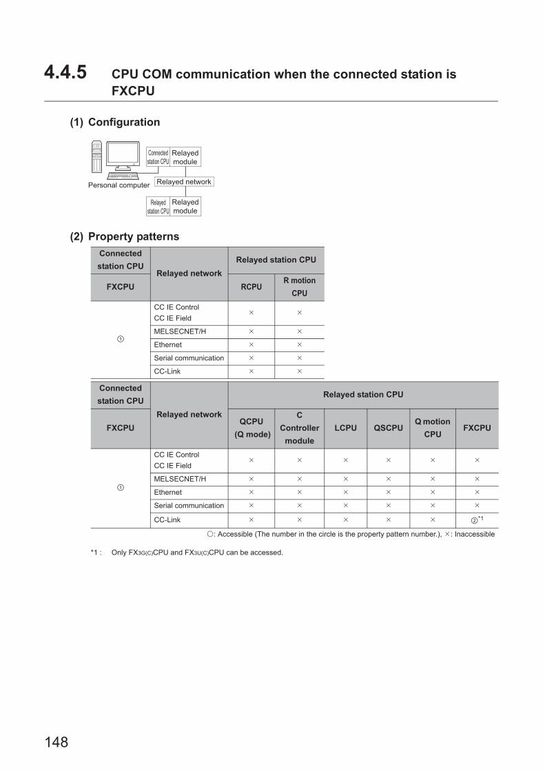
148
4.4.5 CPU COM communication when the connected station is FXCPU
(1) Configuration
(2) Property patterns
*1 : Only FX3G(C)CPU and FX3U(C)CPU can be accessed.
Connected
station CPURelayed network
Relayed station CPU
FXCPU RCPUR motion
CPU
CC IE Control
CC IE Field
MELSECNET/H
Ethernet
Serial communication
CC-Link
Connected
station CPU
Relayed network
Relayed station CPU
FXCPUQCPU
(Q mode)
C
Controller
module
LCPU QSCPUQ motion
CPUFXCPU
CC IE Control
CC IE Field
MELSECNET/H
Ethernet
Serial communication
CC-Link *1
: Accessible (The number in the circle is the property pattern number.), : Inaccessible
Personal computer
Connected
station CPU
Relayed
station CPU
Relayed
module
Relayed network
Relayed
module

149
CHAPTER 4 PROPERTY SETTINGS OF COMMUNICATION PATHS
4
4.4 CO
M C
om
munication
4.4.5 CP
U C
OM
com
munication w
hen the connecte
d station is FX
CP
U
(3) Property listThe following table shows the property settings of communication paths. The setting is not necessary for those
properties without description.
Property Default valueProperty pattern
ActBaudRate19200
(BAUDRATE_19200)
FX0(S), FX0N, FX1, FX1S, FX2(C)
(Fixed to BAUDRATE_9600)
FX1N(C), FX2N(C)
(BAUDRATE_9600, BAUDRATE_19200)
FX3S, FX3UC, FX3G(C)
(BAUDRATE_9600, BAUDRATE_19200, BAUDRATE_38400,
BAUDRATE_57600, BAUDRATE_115200)
ActControl 8 (TRC_DTR_OR_RTS) Depending on the used cable.
ActCpuType 34 (CPU_Q02CPU) CPU type corresponding to the target station
ActDestinationIONumber 0 (0x00) Fixed to 0 (0x00) Fixed to 1023 (0x3FF)
ActDidPropertyBit 1 (0x01) 0 (0x00)
ActDsidPropertyBit 1 (0x01) 0 (0x00)
ActIONumber 1023 (0x3FF) Fixed to 0 (0x00)Module number of the
connected station
ActPortNumber 1 (PORT_1) Personal computer side COM port number
ActProtocolType0x04
(PROTOCOL_SERIAL)PROTOCOL_SERIAL(0x04)
ActTimeOut 10000 Any value specified by user in ms units.
ActUnitNumber 0 (0x00) Fixed to 0 (0x00)Target station side module station
number
ActUnitType 0x13 (UNIT_QNCPU) UNIT_FXCPU(0x0F)

150
4.4.6 COM communication when the connected station is inverter
(1) Configuration
(2) Property listThe following table shows the property settings of communication paths. The setting is not necessary for those
properties without description.
When performing inverter communication, the program setting type control cannot be used.Use the utility setting type control.
Property Default valueProperty pattern
ActMxUnitSeries 0 (0x00) 1 (0x01)
ActProtocolType0x04
(PROTOCOL_SERIAL)COMM_RS232C (0x00)
ActStationNumber 255 (0xFF) Inverter station number (0 to 31)
ActCpuType 34 (CPU_Q02CPU) Fixed to INV_A800 (0x1E60)
ActPortNumber 1 (PORT_1) Personal computer side COM port number
ActBaudRate19200
(BAUDRATE_19200)
BAUDRATE_4800, BAUDRATE_9600,
BAUDRATE_19200, BAUDRATE_38400,
BAUDRATE_57600, BAUDRATE_115200
ActTimeOut 10000 Any value specified by user in ms units.
ActCpuTimeOut 0(0x00) Any value specified by user in 10ms units.
ActPacketType 1 (CRLF_CR) CRLF_NONE, CRLF_CR, CRLF_CRLF
ActDataBits 8 (DATABIT_8) DATABIT_7, DATABIT_8
ActParity 1 (ODD_PARITY) NO_PARRITY, ODD_PARITY, EVEN_PARITY
ActStopBits 0 (STOPBIT_ONE) STOPBIT_ONE, STOPBIT_TWO
Personal computer
Inverter

151
CHAPTER 4 PROPERTY SETTINGS OF COMMUNICATION PATHS
4
4.4 CO
M C
om
munication
4.4.7 CO
M com
munication w
hen the connected station is robot controller
4.4.7 COM communication when the connected station is robot controller
(1) Configuration
(2) Property listThe following table shows the property settings of communication paths. The setting is not necessary for those
properties without description.
When robot controller communication, the program setting type control cannot be used.Use the utility setting type control.
Property Default valueProperty pattern
ActProtocolType0x04
(PROTOCOL_SERIAL)RC_PROTOCOL_SERIAL(0x01)
ActCpuType34
(CPU_Q02CPU)Robot controller type(0x013001)
ActPortNumber 1(PORT_1) Personal computer side COM port number
ActBaudRate19200
(BAUDRATE_19200)
BAUDRATE_4800, BAUDRATE_9600,
BAUDRATE_19200, BAUDRATE_38400,
BAUDRATE_57600, BAUDRATE_115200
ActTimeOut 10000 Any value specified by user in ms units.
ActCpuTimeOut 0(0x00) Any value specified by user in 10ms units.
ActDataBits 8(DATABIT_8) DATABIT_7, DATABIT_8
ActParity 1(ODD_PARITY) NO_PARRITY, ODD_PARITY, EVEN_PARITY
ActStopBits 0(STOPBIT_ONE) ONESTOPBIT, ONE5STOPBITS, TWOSTOPBITS
ActMultiDropChanne
lNumber0(0x00) Retry count
ActThroughNetwork
Type0(0x00) Procedural/Nonprocedural (0/1)
ActMxUnitSeries 0(0x00) 2(0x02)
Personal computer
Robot controller

152
4.5 USB Communication
4.5.1 USB communication when the connected station is RCPU
(1) Configuration
(2) Property patterns
*1 : Since CC-Link IE Controller Network is not supported, RCPU relayed by CC-Link IE Controller Network cannot be accessed.
Connected
station CPURelayed network
Relayed station CPU
RCPU RCPUR motion
CPU
CC IE Control
CC IE Field*1
MELSECNET/H
Ethernet
Serial communication
CC-Link
Connected
station CPU
Relayed network
Relayed station CPU
RCPUQCPU
(Q mode)
C
Controller
module
LCPU QSCPUQ motion
CPUFXCPU
CC IE Control
CC IE Field
MELSECNET/H
Ethernet
Serial communication
CC-Link
: Accessible (The number in the circle is the property pattern number.), : Inaccessible
Personal computer
Connected
station CPU
Relayed
module
Relayed network
Relayed
station CPU
Relayed
module

153
CHAPTER 4 PROPERTY SETTINGS OF COMMUNICATION PATHS
4
4.5 US
B C
omm
unication4.5.1 U
SB
comm
unication w
hen the connected station is RC
PU
(3) Property listThe following table shows the property settings of communication paths. The setting is not necessary for those
properties without description.
Property Default valueProperty pattern
*1
ActCpuType34
(CPU_Q02CPU)CPU type corresponding to the target station
ActDestination
IONumber *20 (0x00) Fixed to 0 (0x00) Fixed to 0 (0x00)
Target station side
For single CPU
Fixed to 1023 (0x3FF)
For multiple CPUs
Connected CPU:
1023 (0x3FF)
No. 1: 992 (0x3E0)
No. 2: 993 (0x3E1)
No. 3: 994 (0x3E2)
No. 4: 995 (0x3E3)
For Redundant CPU
Control system:
976 (0x3D0)
No specification:
1023 (0x3FF)
Target station side
For single CPU
Fixed to 1023 (0x3FF)
For multiple CPUs
Connected CPU:
1023 (0x3FF)
No. 1: 992 (0x3E0)
No. 2: 993 (0x3E1)
No. 3: 994 (0x3E2)
No. 4: 995 (0x3E3)
For Redundant CPU
Control system:
976 (0x3D0)
No specification:
1023 (0x3FF)
ActDidProperty
Bit1 (0x01) Fixed to 1 (0x01) Fixed to 1 (0x01) Fixed to 0 (0x00) Fixed to 0 (0x00)
ActDsidProperty
Bit1 (0x01) Fixed to 1 (0x01) Fixed to 1 (0x01) Fixed to 0 (0x00) Fixed to 0 (0x00)
ActIntelligent
PreferenceBit0 (0x00) Fixed to 0 (0x00) Fixed to 0 (0x00)
Target station
RCPU,
QCPU (Q mode),
C Controller module,
LCPU : 1 (0x01)
Other than the
above : 0 (0x00)
Target station
RCPU,
QCPU (Q mode),
C Controller module,
LCPU : 1 (0x01)
Other than the
above : 0 (0x00)
ActIONumber *2 1023 (0x3FF)
For single CPU
Fixed to 1023 (0x3FF)
For multiple CPUs
Connected CPU:
1023 (0x3FF)
No. 1: 992 (0x3E0)
No. 2: 993 (0x3E1)
No. 3: 994 (0x3E2)
No. 4: 995 (0x3E3)
For Redundant CPU
Control system:
976 (0x3D0)
No specification:
1023 (0x3FF)
Target station side
For single CPU
Fixed to 1023 (0x3FF)
For multiple CPUs
Connected CPU:
1023 (0x3FF)
No. 1: 992 (0x3E0)
No. 2: 993 (0x3E1)
No. 3: 994 (0x3E2)
No. 4: 995 (0x3E3)
For Redundant CPU
Control system:
976 (0x3D0)
No specification:
1023 (0x3FF)
Connected station side
module I/O address
Connected station side
module I/O address
ActMultiDrop
ChannelNumber *30 (0x00) Fixed to 0 (0x00) Fixed to 0 (0x00)
Multi-drop channel
numberFixed to 0 (0x00)
ActNetwork
Number0 (0x00) Fixed to 0 (0x00)
Target station side
module network
number
Fixed to 0 (0x00) Fixed to 0 (0x00)

154
*1 : Note the following considerations when accessing via Ethernet module (R series-compatible E71). • For ActNetworkNumber and ActStationNumber, specify the value set in the parameter setting of the target station side R series-
compatible E71. • Set "Station No. IP information" in the parameter setting of R series-compatible E71. When setting the parameter, specify the
setting other than the automatic response system (any of the IP address calculation system, table conversion system, and combined system) for "Station No. IP information system".
*2 : For the I/O address, specify the value of the actual start I/O number divided by 16.*3 : Specify the following value for the channel number to be multi-drop linked.
0: Default channel of module1: Channel 12: Channel 2
ActProtocolType
0x04
(PROTOCOL_
SERIAL)
PROTOCOL_USB
ActPacketType0x01(PACKET_
PLC1)PACKET_PLC1
ActStation
Number255 (0xFF) Fixed to 255 (0xFF)
Target station side
module station numberFixed to 255 (0xFF) Fixed to 255 (0xFF)
ActConnectUnit
Number0(0x00) Fixed to 0 (0x00)
ActPortNumber 1(PORT_1) Fixed to 1 (PORT_1)
ActBaudRate
19200
(BAUDRATE_
19200)
Fixed to 0 (0x00)
ActHostAddress 1.1.1.1 Fixed to NULL
ActCpuTimeOut 0(0x00) Fixed to 0 (0x00)
ActControl8(TRC_DTR_
OR_RTS)Fixed to 0 (0x00)
ActDataBits 8(DATABIT_8) Fixed to 0 (0x00)
ActParity1
(ODD_PARITY)Fixed to 0 (0x00)
ActStopBits0(STOPBIT_
ONE)Fixed to 0 (0x00)
ActSumCheck0(NO_SUM_
CHECK)Fixed to 0 (0x00)
ActSource
NetworkNumber0(0x00) Fixed to 0 (0x00)
ActSourceStation
Number0(0x00) Fixed to 0 (0x00)
ActDestination
PortNumber0(0x00) Fixed to 0 (0x00)
ActThrough
NetworkType0 (0x00)
MELSECNET/10 is not included. : 0 (0x00)
MELSECNET/10 is included. : 1 (0x01)
ActTimeOut 10000 Any value specified by user in ms units
ActUnitNumber 0 (0x00) Fixed to 0 (0x00) Fixed to 0 (0x00)Target station side
module station number
Target station side
module station number
ActUnitType0x13
(UNIT_QNCPU)UNIT_RUSB
Property Default valueProperty pattern
*1

155
CHAPTER 4 PROPERTY SETTINGS OF COMMUNICATION PATHS
4
4.5 US
B C
omm
unication4.5.2 U
SB
comm
unication w
hen the connected station is R m
otion C
PU
4.5.2 USB communication when the connected station is R motion CPU
(1) Configuration
(2) Property patterns
*1 : Relayed stations cannot be accessed via R motion CPU.*2 : Only CPU No.2 or later in a multiple CPU configuration can be accessed.
Connected
station CPURelayed network
Relayed station CPU
R motion
CPURCPU
R motion
CPU
*1,*2
CC IE Control
CC IE Field
MELSECNET/H
Ethernet
Serial communication
CC-Link
Connected
station CPU
Relayed network
Relayed station CPU
R motion
CPU
QCPU
(Q mode)
C
Controller
module
LCPU QSCPUQ motion
CPUFXCPU
*1,*2
CC IE Control
CC IE Field
MELSECNET/H
Ethernet
Serial communication
CC-Link
: Accessible (The number in the circle is the property pattern number.), : Inaccessible
Personal computer
Connected
station CPU
Relayed
module
Relayed network
Relayed
station CPU
Relayed
module
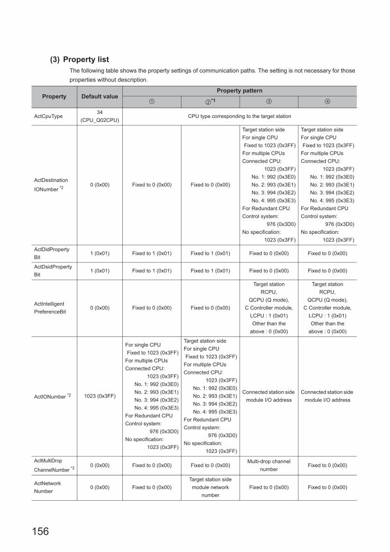
156
(3) Property listThe following table shows the property settings of communication paths. The setting is not necessary for those
properties without description.
Property Default valueProperty pattern
*1
ActCpuType34
(CPU_Q02CPU)CPU type corresponding to the target station
ActDestination
IONumber *20 (0x00) Fixed to 0 (0x00) Fixed to 0 (0x00)
Target station side
For single CPU
Fixed to 1023 (0x3FF)
For multiple CPUs
Connected CPU:
1023 (0x3FF)
No. 1: 992 (0x3E0)
No. 2: 993 (0x3E1)
No. 3: 994 (0x3E2)
No. 4: 995 (0x3E3)
For Redundant CPU
Control system:
976 (0x3D0)
No specification:
1023 (0x3FF)
Target station side
For single CPU
Fixed to 1023 (0x3FF)
For multiple CPUs
Connected CPU:
1023 (0x3FF)
No. 1: 992 (0x3E0)
No. 2: 993 (0x3E1)
No. 3: 994 (0x3E2)
No. 4: 995 (0x3E3)
For Redundant CPU
Control system:
976 (0x3D0)
No specification:
1023 (0x3FF)
ActDidProperty
Bit1 (0x01) Fixed to 1 (0x01) Fixed to 1 (0x01) Fixed to 0 (0x00) Fixed to 0 (0x00)
ActDsidProperty
Bit1 (0x01) Fixed to 1 (0x01) Fixed to 1 (0x01) Fixed to 0 (0x00) Fixed to 0 (0x00)
ActIntelligent
PreferenceBit0 (0x00) Fixed to 0 (0x00) Fixed to 0 (0x00)
Target station
RCPU,
QCPU (Q mode),
C Controller module,
LCPU : 1 (0x01)
Other than the
above : 0 (0x00)
Target station
RCPU,
QCPU (Q mode),
C Controller module,
LCPU : 1 (0x01)
Other than the
above : 0 (0x00)
ActIONumber *2 1023 (0x3FF)
For single CPU
Fixed to 1023 (0x3FF)
For multiple CPUs
Connected CPU:
1023 (0x3FF)
No. 1: 992 (0x3E0)
No. 2: 993 (0x3E1)
No. 3: 994 (0x3E2)
No. 4: 995 (0x3E3)
For Redundant CPU
Control system:
976 (0x3D0)
No specification:
1023 (0x3FF)
Target station side
For single CPU
Fixed to 1023 (0x3FF)
For multiple CPUs
Connected CPU:
1023 (0x3FF)
No. 1: 992 (0x3E0)
No. 2: 993 (0x3E1)
No. 3: 994 (0x3E2)
No. 4: 995 (0x3E3)
For Redundant CPU
Control system:
976 (0x3D0)
No specification:
1023 (0x3FF)
Connected station side
module I/O address
Connected station side
module I/O address
ActMultiDrop
ChannelNumber *30 (0x00) Fixed to 0 (0x00) Fixed to 0 (0x00)
Multi-drop channel
numberFixed to 0 (0x00)
ActNetwork
Number0 (0x00) Fixed to 0 (0x00)
Target station side
module network
number
Fixed to 0 (0x00) Fixed to 0 (0x00)

157
CHAPTER 4 PROPERTY SETTINGS OF COMMUNICATION PATHS
4
4.5 US
B C
omm
unication4.5.2 U
SB
comm
unication w
hen the connected station is R m
otion C
PU
*1 : Note the following considerations when accessing via Ethernet module (R series-compatible E71). • For ActNetworkNumber and ActStationNumber, specify the value set in the parameter setting of the target station side R series-
compatible E71. • Set "Station No. IP information" in the parameter setting of R series-compatible E71. When setting the parameter, specify the
setting other than the automatic response system (any of the IP address calculation system, table conversion system, and combined system) for "Station No. IP information system".
*2 : For the I/O address, specify the value of the actual start I/O number divided by 16.*3 : Specify the following value for the channel number to be multi-drop linked.
0: Default channel of module1: Channel 12: Channel 2
ActProtocolType
0x04
(PROTOCOL_
SERIAL)
PROTOCOL_USB
ActStation
Number255 (0xFF) Fixed to 255 (0xFF)
Target station side
module station numberFixed to 255 (0xFF) Fixed to 255 (0xFF)
ActThrough
NetworkType0 (0x00)
MELSECNET/10 is not included. : 0 (0x00)
MELSECNET/10 is included. : 1 (0x01)
ActTimeOut 10000 Any value specified by user in ms units
ActUnitNumber 0 (0x00) Fixed to 0 (0x00) Fixed to 0 (0x00)Target station side
module station number
Target station side
module station number
ActUnitType0x13
(UNIT_QNCPU)UNIT_RUSB
Property Default valueProperty pattern
*1

158
4.5.3 USB communication when the connected station is QCPU (Q mode)
(1) Configuration
(2) Property patterns
Connected
station CPURelayed network
Relayed station CPU
QCPU
(Q mode)RCPU
R motion
CPU
CC IE Control
CC IE Field
MELSECNET/H
Ethernet
Serial communication
CC-Link
Connected
station CPU
Relayed network
Relayed station CPU
QCPU
(Q mode)
QCPU
(Q mode)
C
Controller
module
LCPU QSCPUQ motion
CPUFXCPU
CC IE Control
CC IE Field *1 *2 *1 *1
MELSECNET/H
Ethernet
Serial communication *3
CC-Link *4
Personal computer
Connected
station CPU
Relayed
module
Relayed network
Relayed
station CPU
Relayed
module

159
CHAPTER 4 PROPERTY SETTINGS OF COMMUNICATION PATHS
4
4.5 US
B C
omm
unication4.5.3 U
SB
comm
unication w
hen the connected station is QC
PU
(Q m
ode)
*1 : Since CC-Link IE Field Network is not supported, R motion CPU, Q12DCCPU-V (Basic mode), QSCPU, and Q motion CPU relayed by CC-Link IE Field Network cannot be accessed.
*2 : Since CC-Link IE Controller Network is not supported, LCPU relayed by CC-Link IE Controller Network cannot be accessed.
*3 : For Redundant CPU, serial communication modules on the main base cannot be accessed.*4 : Supported by FX3G(C)CPU and FX3U(C)CPU within the own network only.
Connected
station CPURelayed network
Relayed station CPU
C Controller
moduleRCPU
R motion
CPU
CC IE Control
CC IE Field
MELSECNET/H
Ethernet
Serial communication
CC-Link
Connected
station CPU
Relayed network
Relayed station CPU
C Controller
module
QCPU
(Q mode)
C
Controller
module
LCPU QSCPUQ motion
CPUFXCPU
CC IE Control
CC IE Field *1 *2 *1 *1
MELSECNET/H
Ethernet
Serial communication
CC-Link
: Accessible (The number in the circle is the property pattern number.), : Inaccessible

160
(3) Property listThe following table shows the property settings of communication paths. The setting is not necessary for those
properties without description.
Property Default valueProperty pattern
*1
ActCpuType34
(CPU_Q02CPU)CPU type corresponding to the target station
ActDestination
IONumber0 (0x00) Fixed to 0 (0x00) Fixed to 0 (0x00)
Target station side
For single CPU
Fixed to 1023 (0x3FF)
For multiple CPUs
Connected CPU:
1023 (0x3FF)
No. 1: 992 (0x3E0)
No. 2: 993 (0x3E1)
No. 3: 994 (0x3E2)
No. 4: 995 (0x3E3)
For Redundant CPU
Control system:
976 (0x3D0)
No specification:
1023 (0x3FF)
Target station side
For single CPU
Fixed to 1023 (0x3FF)
For multiple CPUs
Connected CPU:
1023 (0x3FF)
No. 1: 992 (0x3E0)
No. 2: 993 (0x3E1)
No. 3: 994 (0x3E2)
No. 4: 995 (0x3E3)
For Redundant CPU
Control system:
976 (0x3D0)
No specification:
1023 (0x3FF)
ActDidProperty
Bit1 (0x01) Fixed to 1 (0x01) Fixed to 1 (0x01) Fixed to 0 (0x00) Fixed to 0 (0x00)
ActDsidProperty
Bit1 (0x01) Fixed to 1 (0x01) Fixed to 1 (0x01) Fixed to 0 (0x00) Fixed to 0 (0x00)
ActIntelligent
PreferenceBit0 (0x00) Fixed to 0 (0x00) Fixed to 0 (0x00)
Target station
Q mode,
C Controller module,
LCPU :1 (0x01)
Other than the
above :0 (0x00)
Target station
Q mode,
C Controller module,
LCPU :1 (0x01)
Other than the
above :0 (0x00)
ActIONumber*2 1023 (0x3FF)
Target station side
For single CPU
Fixed to 1023 (0x3FF)
For multiple CPUs
Connected CPU:
1023 (0x3FF)
No. 1: 992 (0x3E0)
No. 2: 993 (0x3E1)
No. 3: 994 (0x3E2)
No. 4: 995 (0x3E3)
For Redundant CPU
Control system:
976 (0x3D0)
No specification:
1023 (0x3FF)
Target station side
For single CPU
Fixed to 1023 (0x3FF)
For multiple CPUs
Connected CPU:
1023 (0x3FF)
No. 1: 992 (0x3E0)
No. 2: 993 (0x3E1)
No. 3: 994 (0x3E2)
No. 4: 995 (0x3E3)
For Redundant CPU
Control system:
976 (0x3D0)
No specification:
1023 (0x3FF)
Connected station side
module I/O address
Connected station side
module I/O address
ActMultiDrop
ChannelNumber*30 (0x00) Fixed to 0 (0x00) Fixed to 0 (0x00)
Multi-drop channel
numberFixed to 0 (0x00)
ActNetwork
Number0 (0x00) Fixed to 0 (0x00)
Target station side
module network
number
Fixed to 0 (0x00) Fixed to 0 (0x00)

161
CHAPTER 4 PROPERTY SETTINGS OF COMMUNICATION PATHS
4
4.5 US
B C
omm
unication4.5.3 U
SB
comm
unication w
hen the connected station is QC
PU
(Q m
ode)
*1 : Note the following considerations when accessing via Ethernet module (Q series-compatible E71). • For ActNetworkNumber and ActStationNumber, specify the value set in the parameter setting of the target station side Q series-
compatible E71. • Set "Station No. IP information" in the parameter setting of Q series-compatible E71. When setting the parameter, specify the
setting other than the automatic response system (any of the IP address calculation system, table conversion system, and combined system) for "Station No. IP information system".
*2 : For the I/O address, specify the value of the actual start I/O number divided by 16.*3 : Specify the following value for the channel number to be multi-drop linked.
0: Default channel of module1: Channel 12: Channel 2
ActProtocolType
0x04
(PROTOCOL_
SERIAL)
PROTOCOL_USB (0x0D)
ActStation
Number255 (0xFF) Fixed to 255 (0xFF)
Target station side
module station numberFixed to 255 (0xFF) Fixed to 255 (0xFF)
ActThrough
NetworkType0 (0x00)
MELSECNET/10 is not included. : 0 (0x00)
MELSECNET/10 is included. : 1 (0x01)
ActTimeOut 10000 Any value specified by user in ms units
ActUnitNumber 0 (0x00) Fixed to 0 (0x00) Fixed to 0 (0x00)Target station side
module station number
Target station side
module station number
ActUnitType0x13
(UNIT_QNCPU)UNIT_QNUSB (0x16)
Property Default valueProperty pattern
*1

162
4.5.4 USB communication when the connected station is LCPU
(1) Configuration
(2) Property patterns
*1 : Since CC-Link IE Controller Network is not supported, LCPU relayed by CC-Link IE Controller Network cannot be accessed.
*2 : Since CC-Link IE Field Network is not supported, Q12DCCPU-V (Basic mode) relayed by CC-Link IE Field Network cannot be accessed.
*3 : For Redundant CPU, serial communication modules on the main base cannot be accessed.
Connected
station CPURelayed network
Relayed station CPU
LCPU RCPUR motion
CPU
CC IE Field*1
MELSECNET/H
Ethernet
Serial communication
CC-Link
Connected
station CPU
Relayed network
Relayed station CPU
LCPUQCPU
(Q mode)
C
Controller
module
LCPU QSCPUQ motion
CPUFXCPU
CC IE Field*1 *2
MELSECNET/H
Ethernet
Serial communication *3
CC-Link
: Accessible (The number in the circle is the property pattern number.), : Inaccessible
Personal computer
Connected
station CPU
Relayed
module
Relayed network
Relayed
station CPU
Relayed
module

163
CHAPTER 4 PROPERTY SETTINGS OF COMMUNICATION PATHS
4
4.5 US
B C
omm
unication4.5.4 U
SB
comm
unication w
hen the connected station is LCP
U
(3) Property listThe following table shows the property settings of communication paths. The setting is not necessary for those
properties without description.
Property Default valueProperty pattern
ActCpuType34
(CPU_Q02CPU)CPU type corresponding to the target station
ActDestination
IONumber0 (0x00) Fixed to 0 (0x00)
Target station side
For single CPU
Fixed to 1023 (0x3FF)
For multiple CPUs
Connected CPU:
1023 (0x3FF)
No. 1: 992 (0x3E0)
No. 2: 993 (0x3E1)
No. 3: 994 (0x3E2)
No. 4: 995 (0x3E3)
For Redundant CPU
Control system:
976 (0x3D0)
No specification:
1023 (0x3FF)
Target station side
For single CPU
Fixed to 1023 (0x3FF)
For multiple CPUs
Connected CPU:
1023 (0x3FF)
No. 1: 992 (0x3E0)
No. 2: 993 (0x3E1)
No. 3: 994 (0x3E2)
No. 4: 995 (0x3E3)
For Redundant CPU
Control system:
976 (0x3D0)
No specification:
1023 (0x3FF)
Fixed to 0 (0x00)
ActDidPropertyBit 1 (0x01) Fixed to 1 (0x01) Fixed to 0 (0x00) Fixed to 0 (0x00) Fixed to 1 (0x01)
ActDsidPropertyBit 1 (0x01) Fixed to 1 (0x01) Fixed to 0 (0x00) Fixed to 0 (0x00) Fixed to 1 (0x01)
ActIntelligent
PreferenceBit0 (0x00) Fixed to 0 (0x00)
Target station
Q mode,
C Controller module,
LCPU :1 (0x01)
Other than the
above :0 (0x00)
Target station
Q mode,
C Controller module,
LCPU :1 (0x01)
Other than the
above :0 (0x00)
Fixed to 0 (0x00)
ActIONumber*1 1023 (0x3FF)Fixed to 1023
(0x3FF)
Connected station side
module I/O address
Connected station side
module I/O address
Target station side
For single CPU
Fixed to 1023 (0x3FF)
For multiple CPUs
Connected CPU:
1023 (0x3FF)
No. 1: 992 (0x3E0)
No. 2: 993 (0x3E1)
No. 3: 994 (0x3E2)
No. 4: 995 (0x3E3)
For Redundant CPU
Control system:
976 (0x3D0)
No specification:
1023 (0x3FF)
ActMultiDrop
ChannelNumber*20 (0x00) Fixed to 0 (0x00)
Multi-drop channel
numberFixed to 0 (0x00) Fixed to 0 (0x00)
ActNetworkNumber 0 (0x00) Fixed to 0 (0x00) Fixed to 0 (0x00) Fixed to 0 (0x00)
Target station side
module network
number
ActProtocolType
0x04
(PROTOCOL_
SERIAL)
PROTOCOL_USB (0x0D)
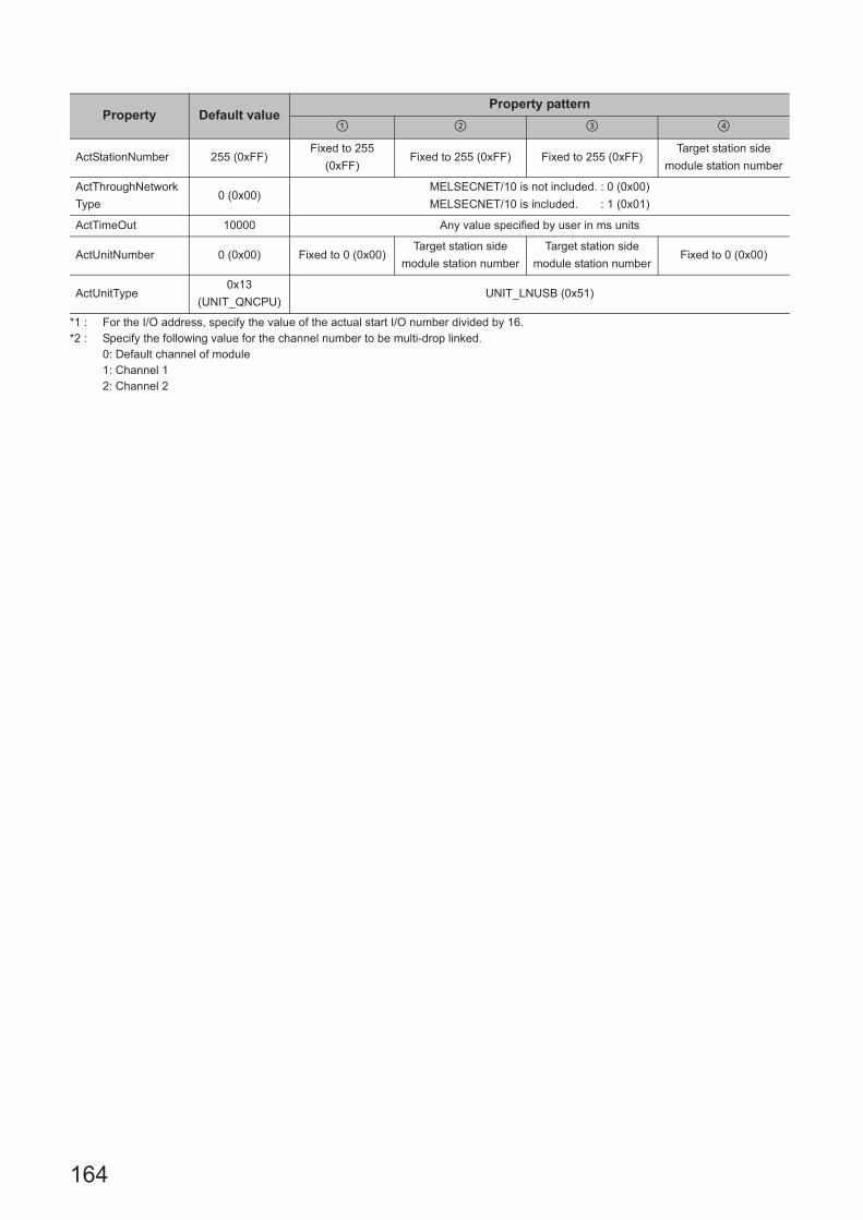
164
*1 : For the I/O address, specify the value of the actual start I/O number divided by 16.*2 : Specify the following value for the channel number to be multi-drop linked.
0: Default channel of module1: Channel 12: Channel 2
ActStationNumber 255 (0xFF)Fixed to 255
(0xFF)Fixed to 255 (0xFF) Fixed to 255 (0xFF)
Target station side
module station number
ActThroughNetwork
Type0 (0x00)
MELSECNET/10 is not included. : 0 (0x00)
MELSECNET/10 is included. : 1 (0x01)
ActTimeOut 10000 Any value specified by user in ms units
ActUnitNumber 0 (0x00) Fixed to 0 (0x00)Target station side
module station number
Target station side
module station numberFixed to 0 (0x00)
ActUnitType0x13
(UNIT_QNCPU)UNIT_LNUSB (0x51)
Property Default valueProperty pattern

165
CHAPTER 4 PROPERTY SETTINGS OF COMMUNICATION PATHS
4
4.5 US
B C
omm
unication4.5.5 U
SB
comm
unication w
hen the connected station is QS
CP
U
4.5.5 USB communication when the connected station is QSCPU
(1) Configuration
(2) Property patterns
*1 : Relayed stations cannot be accessed via QSCPU.
(3) Property listThe following table shows the property settings of communication paths. The setting is not necessary for those
properties without description.
Connected
station CPURelayed network
Relayed station CPU
QSCPU RCPUR motion
CPU
*1
CC IE Control
CC IE Field
MELSECNET/H
Ethernet
Serial communication
CC-Link
Connected
station CPU
Relayed network
Relayed station CPU
QSCPUQCPU
(Q mode)
C
Controller
module
LCPU QSCPUQ motion
CPUFXCPU
*1
CC IE Control
CC IE Field
MELSECNET/H
Ethernet
Serial communication
CC-Link
: Accessible (The number in the circle is the property pattern number.), : Inaccessible
Property Default valueProperty pattern
ActCpuType 34 (CPU_Q02CPU) CPU type corresponding to the target station
ActProtocolType0x04
(PROTOCOL_SERIAL)PROTOCOL_USB (0x0D)
ActTimeOut 10000 Any value specified by user in ms units
ActUnitType 0x13 (UNIT_QNCPU) UNIT_QSUSB (0x29)
Personal computer
Connected
station CPU
Relayed
module
Relayed network
Relayed
station CPU
Relayed
module

166
4.5.6 USB communication when the connected station is Q motion CPU
(1) Configuration
(2) Property patterns
*1 : Relayed stations cannot be accessed when the Q motion CPU is Q172CPU, Q173CPU, Q172HCPU, or Q173HCPU.
Connected
station CPURelayed network
Relayed station CPU
Q motion
CPURCPU
R motion
CPU
*1
CC IE Control
CC IE Field
MELSECNET/H
Ethernet
Serial communication
CC-Link
Connected
station CPU
Relayed network
Relayed station CPU
Q motion
CPU
QCPU
(Q mode)
C
Controller
module
LCPU QSCPUQ motion
CPUFXCPU
*1
CC IE Control
CC IE Field
MELSECNET/H
Ethernet
Serial communication
CC-Link
: Accessible (The number in the circle is the property pattern number.), : Inaccessible
Personal computer
Connected
station CPU
Relayed
module
Relayed network
Relayed
station CPU
Relayed
module
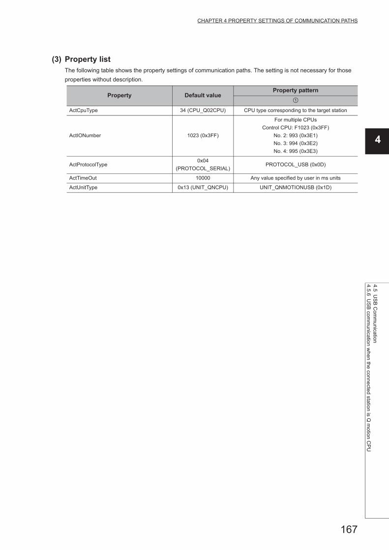
167
CHAPTER 4 PROPERTY SETTINGS OF COMMUNICATION PATHS
4
4.5 US
B C
omm
unication4.5.6 U
SB
comm
unication w
hen the connected station is Q m
otion CP
U
(3) Property listThe following table shows the property settings of communication paths. The setting is not necessary for those
properties without description.
Property Default valueProperty pattern
ActCpuType 34 (CPU_Q02CPU) CPU type corresponding to the target station
ActIONumber 1023 (0x3FF)
For multiple CPUs
Control CPU: F1023 (0x3FF)
No. 2: 993 (0x3E1)
No. 3: 994 (0x3E2)
No. 4: 995 (0x3E3)
ActProtocolType0x04
(PROTOCOL_SERIAL)PROTOCOL_USB (0x0D)
ActTimeOut 10000 Any value specified by user in ms units
ActUnitType 0x13 (UNIT_QNCPU) UNIT_QNMOTIONUSB (0x1D)

168
4.5.7 USB communication when the connected station is FXCPU
(1) Configuration
(2) Property patterns
*1 : Only FX3G(C)CPU and FX3U(C)CPU can be accessed.
Connected
station CPURelayed network
Relayed station CPU
FXCPU RCPUR motion
CPU
CC IE Control
CC IE Field
MELSECNET/H
Ethernet
Serial communication
CC-Link
Connected
station CPU
Relayed network
Relayed station CPU
FXCPUQCPU
(Q mode)
C
Controller
module
LCPU QSCPUQ motion
CPUFXCPU
CC IE Control
CC IE Field
MELSECNET/H
Ethernet
Serial communication
CC-Link *1
: Accessible (The number in the circle is the property pattern number.), : Inaccessible
Personal computer
Connected
station CPU
Relayed
module
Relayed network
Relayed
station CPU
Relayed
module

169
CHAPTER 4 PROPERTY SETTINGS OF COMMUNICATION PATHS
4
4.5 US
B C
omm
unication4.5.7 U
SB
comm
unication w
hen the connected station is FX
CP
U
(3) Property listThe following table shows the property settings of communication paths. The setting is not necessary for those
properties without description.
Property Default valueProperty pattern
ActCpuType 34 (CPU_Q02CPU) CPU type corresponding to the target station
ActDestinationIONumber 0 (0x00) Fixed to 0 (0x00) Fixed to 1023 (0x3FF)
ActIONumber 1023 (0x3FF) Fixed to 0 (0x00)Module number of the
connected station
ActProtocolType0x04
(PROTOCOL_SERIAL)PROTOCOL_USB (0x0D)
ActTimeOut 10000 Any value specified by user in ms units
ActUnitNumber 0 (0x00) Fixed to 0 (0x00)Target station side module
station number
ActUnitType 0x13 (UNIT_QNCPU) UNIT_FXCPU (0x0F)

170
4.5.8 USB communication when the connected station is inverter
(1) Configuration
(2) Property listThe following table shows the property settings of communication paths. The setting is not necessary for those
properties without description.
When performing inverter communication, the program setting type control cannot be used.Use the utility setting type control.
Property Default valueProperty pattern
ActMxUnitSeries 0 (0x00) 1 (0x01)
ActProtocolType0x04
(PROTOCOL_SERIAL)COMM_USB (0x01)
ActStationNumber 255 (0xFF) Inverter station number (0 to 31)
ActCpuType 34 (CPU_Q02CPU) Fixed to INV_A800 (0x1E60)
ActTimeOut 10000 Any value specified by user in ms units.
ActCpuTimeOut 0(0x00) Any value specified by user in 10ms units.
Personal computer
Inverter

171
CHAPTER 4 PROPERTY SETTINGS OF COMMUNICATION PATHS
4
4.5 US
B C
omm
unication4.5.9 U
SB
comm
unication w
hen the connected station is robot controller
4.5.9 USB communication when the connected station is robot controller
(1) Configuration
(2) Property listThe following table shows the property settings of communication paths. The setting is not necessary for those
properties without description.
When robot controller communication, the program setting type control cannot be used.Use the utility setting type control.
Property Default valueProperty pattern
ActProtocolType0x04
(PROTOCOL_SERIAL)RC_PROTOCOL_USB(0x04)
ActCpuType34
(CPU_Q02CPU)Robot controller type(0x013001)
ActTimeOut 10000 Any value specified by user in ms units.
ActCpuTimeOut 0(0x00) Any value specified by user in 10ms units.
ActMultiDropChanne
lNumber0(0x00) Retry count
ActMxUnitSeries 0(0x00) 2(0x02)
Personal computer
Robot controller

172
4.6 MELSECNET/H Communication
(1) Configuration
(2) Property patterns
Own
board
Connected station CPU
Relayed network
Relayed station CPU
QCPU
(Q mode)QSCPU
Q motion
CPURCPU
R motion
CPU
*1 *1,*5
CC IE Control
CC IE Field
MELSECNET/H
Ethernet
Serial communication
CC-Link
Own
board
Connected station CPU
Relayed network
Relayed station CPU
QCPU
(Q mode)QSCPU
Q motion
CPU
QCPU
(Q mode)
C
Controller
module
LCPUQS
CPU
Q
motion
CPU
FX
CPU
*1 *1,*5
CC IE Control
CC IE Field *2 *3 *1,*2
MELSECNET/H *1
Ethernet *1
Serial communication *4
CC-Link
Connectedstation CPU
MELSECNET/H
module
Relayed
module
Relayed network
Relayedstation CPU
Relayed
module
Personal computer
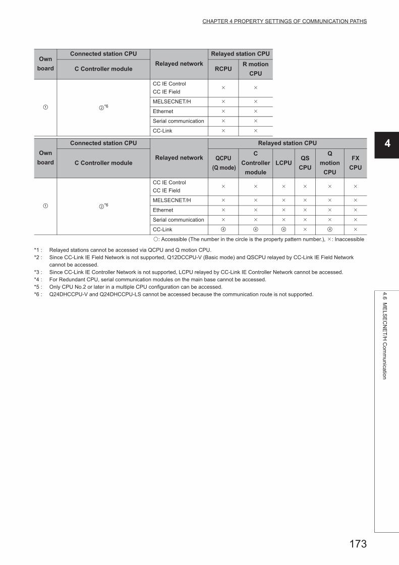
173
CHAPTER 4 PROPERTY SETTINGS OF COMMUNICATION PATHS
4
4.6 ME
LSE
CN
ET
/H C
omm
unication
*1 : Relayed stations cannot be accessed via QCPU and Q motion CPU.*2 : Since CC-Link IE Field Network is not supported, Q12DCCPU-V (Basic mode) and QSCPU relayed by CC-Link IE Field Network
cannot be accessed.*3 : Since CC-Link IE Controller Network is not supported, LCPU relayed by CC-Link IE Controller Network cannot be accessed.*4 : For Redundant CPU, serial communication modules on the main base cannot be accessed.*5 : Only CPU No.2 or later in a multiple CPU configuration can be accessed.*6 : Q24DHCCPU-V and Q24DHCCPU-LS cannot be accessed because the communication route is not supported.
Own
board
Connected station CPU
Relayed network
Relayed station CPU
C Controller module RCPUR motion
CPU
*6
CC IE Control
CC IE Field
MELSECNET/H
Ethernet
Serial communication
CC-Link
Own
board
Connected station CPU
Relayed network
Relayed station CPU
C Controller moduleQCPU
(Q mode)
C
Controller
module
LCPUQS
CPU
Q
motion
CPU
FX
CPU
*6
CC IE Control
CC IE Field
MELSECNET/H
Ethernet
Serial communication
CC-Link
: Accessible (The number in the circle is the property pattern number.), : Inaccessible

174
(3) Property listThe following table shows the property settings of communication paths. The setting is not necessary for those
properties without description.
Property Default valueProperty pattern
ActCpuType34
(CPU_Q02CPU)CPU type corresponding to the target station
ActDestination
IONumber0 (0x00) Fixed to 0 (0x00) Fixed to 0 (0x00)
Target station side
For single CPU
Fixed to
1023 (0x3FF)
For multiple CPUs
Connected CPU:
1023 (0x3FF)
No.1: 992 (0x3E0)
No.2: 993 (0x3E1)
No.3: 994 (0x3E2)
No.4: 995 (0x3E3)
For Redundant CPU
Control system:
976 (0x3D0)
No specification:
1023 (0x3FF)
Target station side
For single CPU
Fixed to
1023 (0x3FF)
For multiple CPUs
Connected CPU:
1023 (0x3FF)
No.1: 992 (0x3E0)
No.2: 993 (0x3E1)
No.3: 994 (0x3E2)
No.4: 995 (0x3E3)
For Redundant CPU
Control system:
976 (0x3D0)
No specification:
1023 (0x3FF)
ActDidPropertyBit 1 (0x01) Fixed to 0 (0x00) Fixed to 1 (0x01) Fixed to 0 (0x00) Fixed to 0 (0x00)
ActDsidPropertyBit 1 (0x01) Fixed to 0 (0x00) Fixed to 1 (0x01) Fixed to 0 (0x00) Fixed to 0 (0x00)
ActIONumber*1 1023 (0x3FF) Fixed to 0 (0x00)
Target station side
For single CPU
Fixed to
1023 (0x3FF)
For multiple CPUs
Connected CPU:
1023 (0x3FF)
No.1: 992 (0x3E0)
No.2: 993 (0x3E1)
No.3: 994 (0x3E2)
No.4: 995 (0x3E3)
For Redundant CPU
Control system:
976 (0x3D0)
No specification:
1023 (0x3FF)
Connected station side
relayed module I/O
address
Connected station side
relayed module I/O
address
ActMultiDrop
ChannelNumber*20 (0x00) Fixed to 0 (0x00) Fixed to 0 (0x00)
Multi-drop channel
numberFixed to 0 (0x00)
ActNetworkNumber 0 (0x00) Fixed to 0 (0x00)
Target station side
module network
number
Connected station side
module network
number
Connected station side
module network
number
ActPortNumber 1 (PORT_1)Port number of personal computer side MELSECNET/H board,
PORT 1 to PORT 4 (first to fourth boards)
ActProtocolType
0x04
(PROTOCOL_
SERIAL)
PROTOCOL_MNETH (0x0F)
ActStationNumber 255 (0xFF)Fixed to 255
(0xFF)
Target station side
module station number
Connected station side
module station number
Connected station side
module station number

175
CHAPTER 4 PROPERTY SETTINGS OF COMMUNICATION PATHS
4
4.6 ME
LSE
CN
ET
/H C
omm
unication
*1 : For the I/O address, specify the value of the actual start I/O number divided by 16.*2 : Specify the following value for the channel number to be multi-drop linked.
0: Default channel of module1: Channel 12: Channel 2
ActThroughNetwork
Type0 (0x00)
MELSECNET/10 is not included. : 0 (0x00)
MELSECNET/10 is included. : 1 (0x01)
ActUnitNumber 0 (0x00) Fixed to 0 (0x00) Fixed to 0 (0x00)Target station side
module station number
Target station side
module station number
ActUnitType0x13
(UNIT_QNCPU)UNIT_MNETHBOARD (0x1E)
Property Default valueProperty pattern

176
4.7 CC-Link IE Controller Network Communication
(1) Configuration
(2) Property patterns
Own
board
Connected station CPU
Relayed network
Relayed station CPU
QCPU
(Q mode)QSCPU
Q motion
CPURCPU
R motion
CPU
*1 *1,*5
CC IE Control
CC IE Field
MELSECNET/H
Ethernet
Serial communication
CC-Link
Own
board
Connected station CPU
Relayed network
Relayed station CPU
QCPU
(Q mode)QSCPU
Q motion
CPU
QCPU
(Q mode)
C
Controller
module
LCPUQS
CPU
Q
motion
CPU
FX
CPU
*1 *1,*5
CC IE Control
CC IE Field *2 *3 *1,*2
MELSECNET/H *1
Ethernet *1
Serial communication *4
CC-Link
Connectedstation CPU
CC-Link IE Controller
Network module
Relayed
module
Relayed network
Relayedstation CPU
Relayed
module
Personal computer

177
CHAPTER 4 PROPERTY SETTINGS OF COMMUNICATION PATHS
4
4.7 CC
-Link IE C
ontroller N
etw
ork Com
munication
*1 : Relayed stations cannot be accessed via QCPU and Q motion CPU.*2 : Since CC-Link IE Field Network is not supported, Q12DCCPU-V (Basic mode) and QSCPU relayed by CC-Link IE Field Network
cannot be accessed.*3 : Since CC-Link IE Controller Network is not supported, LCPU relayed by CC-Link IE Controller Network cannot be accessed.*4 : For Redundant CPU, serial communication modules on the main base cannot be accessed.*5 : Only CPU No.2 or later in a multiple CPU configuration can be accessed.*6 : Q24DHCCPU-V and Q24DHCCPU-LS cannot be accessed because the communication route is not supported.
Own
board
Connected station CPU
Relayed network
Relayed station CPU
C Controller module RCPUR motion
CPU
*6
CC IE Control
CC IE Field
MELSECNET/H
Ethernet
Serial communication
CC-Link
Own
board
Connected station CPU
Relayed network
Relayed station CPU
C Controller moduleQCPU
(Q mode)
C
Controller
module
LCPUQS
CPU
Q
motion
CPU
FX
CPU
*6
CC IE Control
CC IE Field
MELSECNET/H
Ethernet
Serial communication
CC-Link
: Accessible (The number in the circle is the property pattern number.), : Inaccessible

178
(3) Property listThe following table shows the property settings of communication paths. The setting is not necessary for those
properties without description.
Property Default valueProperty pattern
ActCpuType34
(CPU_Q02CPU)CPU type corresponding to the target station
ActDestination
IONumber0 (0x00) Fixed to 0 (0x00) Fixed to 0 (0x00)
Target station side
For single CPU
Fixed to
1023 (0x3FF)
For multiple CPUs
Connected CPU:
1023 (0x3FF)
No.1: 992 (0x3E0)
No.2: 993 (0x3E1)
No.3: 994 (0x3E2)
No.4: 995 (0x3E3)
For Redundant CPU
Control system:
976 (0x3D0)
No specification:
1023 (0x3FF)
Target station side
For single CPU
Fixed to
1023 (0x3FF)
For multiple CPUs
Connected CPU:
1023 (0x3FF)
No.1: 992 (0x3E0)
No.2: 993 (0x3E1)
No.3: 994 (0x3E2)
No.4: 995 (0x3E3)
For Redundant CPU
Control system:
976 (0x3D0)
No specification:
1023 (0x3FF)
ActDidPropertyBit 1 (0x01) Fixed to 1 (0x01) Fixed to 1 (0x01) Fixed to 0 (0x00) Fixed to 0 (0x00)
ActDsidPropertyBit 1 (0x01) Fixed to 1 (0x01) Fixed to 1 (0x01) Fixed to 0 (0x00) Fixed to 0 (0x00)
ActIONumber*1 1023 (0x3FF) 1023 (0x3FF)
Target station side
For single CPU
Fixed to
1023 (0x3FF)
For multiple CPUs
Connected CPU:
1023 (0x3FF)
No.1: 992 (0x3E0)
No.2: 993 (0x3E1)
No.3: 994 (0x3E2)
No.4: 995 (0x3E3)
For Redundant CPU
Control system:
976 (0x3D0)
No specification:
1023 (0x3FF)
Connected station side
relayed module I/O
address
Connected station side
relayed module I/O
address
ActMultiDrop
ChannelNumber*20 (0x00) Fixed to 0 (0x00) Fixed to 0 (0x00)
Multi-drop channel
numberFixed to 0 (0x00)
ActNetworkNumber 0 (0x00) Fixed to 0 (0x00)
Target station side
module network
number
Connected station side
module network
number
Connected station side
module network
number
ActPortNumber 1 (PORT_1)Port number of personal computer side CC-Link IE Controller Network board,
PORT 1 to PORT 4 (first to fourth boards)
ActProtocolType
0x04
(PROTOCOL_
SERIAL)
PROTOCOL_MNETG (0x14)
ActStationNumber 255 (0xFF)Fixed to 255
(0xFF)
Target station side
module station number
Connected station side
module station number
Connected station side
module station number

179
CHAPTER 4 PROPERTY SETTINGS OF COMMUNICATION PATHS
4
4.7 CC
-Link IE C
ontroller N
etw
ork Com
munication
*1 : For the I/O address, specify the value of the actual start I/O number divided by 16.*2 : Specify the following value for the channel number to be multi-drop linked.
0: Default channel of module1: Channel 12: Channel 2
ActThroughNetwork
Type0 (0x00)
MELSECNET/10 is not included. : 0 (0x00)
MELSECNET/10 is included. : 1 (0x01)
ActUnitNumber 0 (0x00) Fixed to 0 (0x00) Fixed to 0 (0x00)Target station side
module station number
Target station side
module station number
ActUnitType0x13
(UNIT_QNCPU)UNIT_MNETGBOARD (0x2B)
Property Default valueProperty pattern

180
4.8 CC-Link IE Field Network Communication
(1) Configuration
(2) Property patterns
Own
board
Connected
station CPURelayed network
Relayed station CPU
QCPU
(Q mode)RCPU
R motion
CPU
CC IE Control
CC IE Field
MELSECNET/H
Ethernet
Serial communication
CC-Link
Own
board
Connected
station CPU
Relayed network
Relayed station CPU
QCPU
(Q mode)
QCPU
(Q mode)
C
Controller
module
LCPU QSCPUQ motion
CPUFXCPU
CC IE Control
CC IE Field *1 *2
MELSECNET/H
Ethernet
Serial communication
CC-Link
Connectedstation CPU
CC-Link IE FieldNetwork module
Relayedmodule
Relayed network
Relayedstation CPU
Relayedmodule
Personal computer

181
CHAPTER 4 PROPERTY SETTINGS OF COMMUNICATION PATHS
4
4.8 CC
-Link IE F
ield Netw
ork Com
mu
nication
*1 : Since CC-Link IE Field Network is not supported, Q12DCCPU-V (Basic mode) relayed by CC-Link IE Field Network cannot be accessed.
*2 : Since CC-Link IE Controller Network is not supported, LCPU relayed by CC-Link IE Controller Network cannot be accessed.
Own
board
Connected
station CPURelayed network
Relayed station CPU
LCPU RCPUR motion
CPU
CC IE Field *2
MELSECNET/H
Ethernet
Serial communication
CC-Link
Own
board
Connected
station CPU
Relayed network
Relayed station CPU
LCPUQCPU
(Q mode)
C
Controller
module
LCPU QSCPUQ motion
CPUFXCPU
CC IE Field *2
MELSECNET/H
Ethernet
Serial communication
CC-Link
: Accessible (The number in the circle is the property pattern number.), : Inaccessible

182
(3) Property listThe following table shows the property settings of communication paths. The setting is not necessary for those
properties without description.
Property Default valueProperty pattern
ActCpuType34
(CPU_Q02CPU)CPU type corresponding to the target station
ActDestination
IONumber0 (0x00) Fixed to 0 (0x00) Fixed to 0 (0x00)
Target station side
For single CPU
Fixed to
1023 (0x3FF)
For multiple CPUs
Connected CPU:
1023 (0x3FF)
No.1: 992 (0x3E0)
No.2: 993 (0x3E1)
No.3: 994 (0x3E2)
No.4: 995 (0x3E3)
For Redundant CPU
Control system:
976 (0x3D0)
No specification:
1023 (0x3FF)
Target station side
For single CPU
Fixed to
1023 (0x3FF)
For multiple CPUs
Connected CPU:
1023 (0x3FF)
No.1: 992 (0x3E0)
No.2: 993 (0x3E1)
No.3: 994 (0x3E2)
No.4: 995 (0x3E3)
For Redundant CPU
Control system:
976 (0x3D0)
No specification:
1023 (0x3FF)
ActDidPropertyBit 1 (0x01) Fixed to 1 (0x01) Fixed to 1 (0x01) Fixed to 0 (0x00) Fixed to 0 (0x00)
ActDsidPropertyBit 1 (0x01) Fixed to 1 (0x01) Fixed to 1 (0x01) Fixed to 0 (0x00) Fixed to 0 (0x00)
ActIONumber*1 1023 (0x3FF)Fixed to 1023
(0x3FF)
Target station side
For single CPU
Fixed to
1023 (0x3FF)
For multiple CPUs
Connected CPU:
1023 (0x3FF)
No.1: 992 (0x3E0)
No.2: 993 (0x3E1)
No.3: 994 (0x3E2)
No.4: 995 (0x3E3)
For Redundant CPU
Control system:
976 (0x3D0)
No specification:
1023 (0x3FF)
Connected station side
relayed module I/O
address
Connected station side
relayed module I/O
address
ActMultiDrop
ChannelNumber*20 (0x00) Fixed to 0 (0x00) Fixed to 0 (0x00)
Multi-drop channel
numberFixed to 0 (0x00)
ActNetworkNumber 0 (0x00) Fixed to 0 (0x00)
Target station side
module network
number
Connected station side
module network
number
Connected station side
module network
number
ActPortNumber 1 (PORT_1)Port number of personal computer side CC-Link IE Field Network board,
PORT 1 to PORT 4 (first to fourth boards)
ActProtocolType
0x04
(PROTOCOL_
SERIAL)
PROTOCOL_CCIEF (0x15)
ActStationNumber 255 (0xFF)Fixed to 255
(0xFF)
Target station side
module station number
Connected station side
module station number
Connected station side
module station number

183
CHAPTER 4 PROPERTY SETTINGS OF COMMUNICATION PATHS
4
4.8 CC
-Link IE F
ield Netw
ork Com
mu
nication
*1 : For the I/O address, specify the value of the actual start I/O number divided by 16.*2 : Specify the following value for the channel number to be multi-drop linked.
0: Default channel of module1: Channel 12: Channel 2
ActThrough
NetworkType0 (0x00)
MELSECNET/10 is not included. : 0 (0x00)
MELSECNET/10 is included. : 1 (0x01)
ActUnitNumber 0 (0x00) Fixed to 0 (0x00) Fixed to 0 (0x00)Target station side
module station number
Target station side
module station number
ActUnitType0x13
(UNIT_QNCPU)UNIT_CCIEFBOARD (0x2F)
Property Default valueProperty pattern
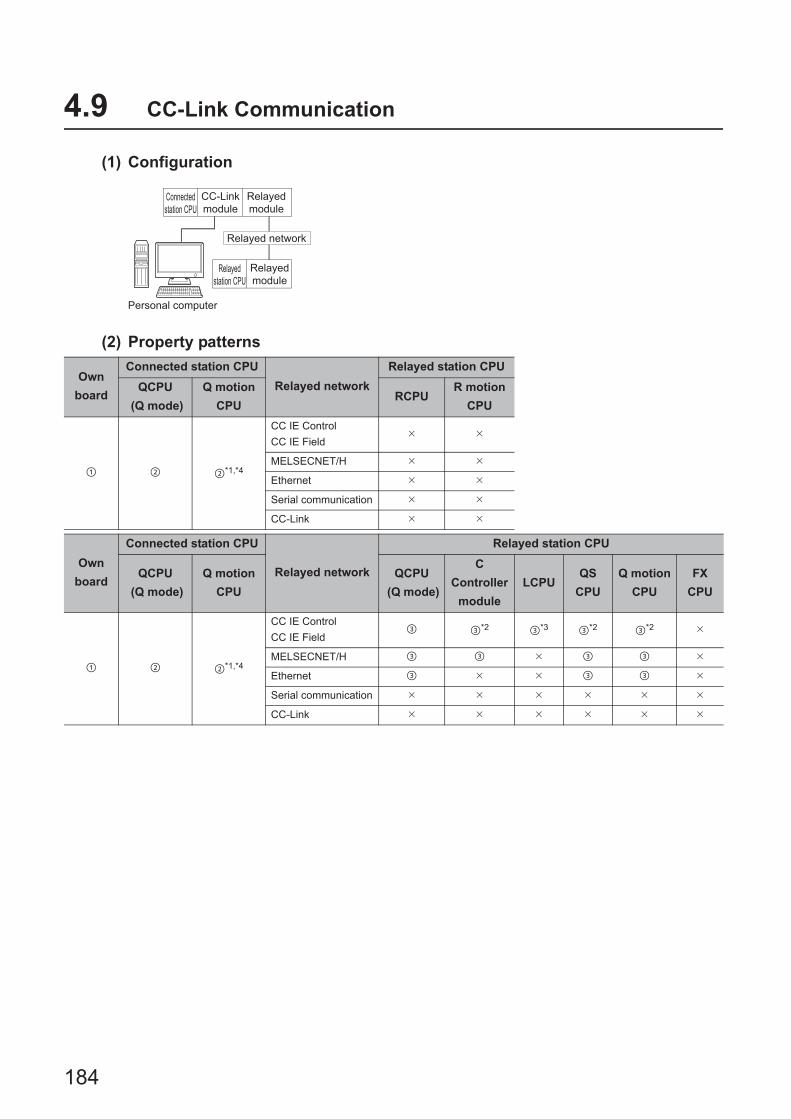
184
4.9 CC-Link Communication
(1) Configuration
(2) Property patterns
Own
board
Connected station CPU
Relayed network
Relayed station CPU
QCPU
(Q mode)
Q motion
CPURCPU
R motion
CPU
*1,*4
CC IE Control
CC IE Field
MELSECNET/H
Ethernet
Serial communication
CC-Link
Own
board
Connected station CPU
Relayed network
Relayed station CPU
QCPU
(Q mode)
Q motion
CPU
QCPU
(Q mode)
C
Controller
module
LCPUQS
CPU
Q motion
CPU
FX
CPU
*1,*4
CC IE Control
CC IE Field *2 *3 *2 *2
MELSECNET/H
Ethernet
Serial communication
CC-Link
Connected
station CPU
CC-Link
module
Relayed
module
Relayed network
Relayed
station CPU
Relayed
module
Personal computer

185
CHAPTER 4 PROPERTY SETTINGS OF COMMUNICATION PATHS
4
4.9 CC
-Link Com
munication
*1 : Relayed stations cannot be accessed via Q motion CPU.*2 : Since CC-Link IE Field Network is not supported, Q12DCCPU-V (Basic mode), QSCPU, and Q motion CPU relayed by CC-Link IE
Field Network cannot be accessed.*3 : Since CC-Link IE Controller Network is not supported, LCPU relayed by CC-Link IE Controller Network cannot be accessed.*4 : Only CPU No.2 or later in a multiple CPU configuration can be accessed.*5 : Q24DHCCPU-V and Q24DHCCPU-LS cannot be accessed because the communication route is not supported.
Own board
Connected station CPU
Relayed network
Relayed station CPU
C Controller module RCPUR motion
CPU
*5
CC IE Control
CC IE Field
MELSECNET/H
Ethernet
Serial communication
CC-Link
Own board
Connected station CPU
Relayed network
Relayed station CPU
C Controller moduleQCPU
(Q mode)
C Controller
moduleLCPU
QSCPU
Q motion CPU
FXCPU
*5
CC IE Control
CC IE Field *2 *2 *2
MELSECNET/H
Ethernet
Serial communication
CC-Link
Own board
Connected station CPU
Relayed network
Relayed station CPU
LCPU RCPUR motion
CPU
CC IE Control
CC IE Field
MELSECNET/H
Ethernet
Serial communication
CC-Link
Own board
Connected station CPU
Relayed network
Relayed station CPU
LCPUQCPU
(Q mode)
C Controller
moduleLCPU
QSCPU
Q motion CPU
FXCPU
CC IE Control
CC IE Field
MELSECNET/H
Ethernet
Serial communication
CC-Link
: Accessible (The number in the circle is the property pattern number.), : Inaccessible
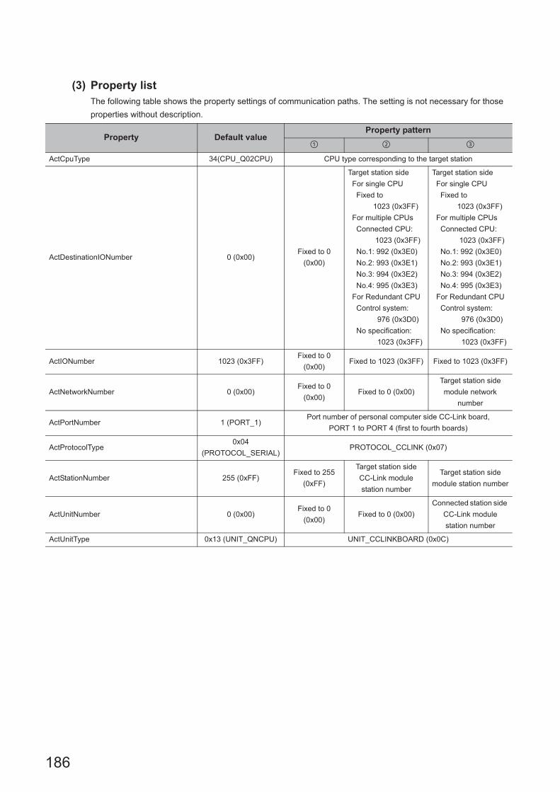
186
(3) Property listThe following table shows the property settings of communication paths. The setting is not necessary for those
properties without description.
Property Default valueProperty pattern
ActCpuType 34(CPU_Q02CPU) CPU type corresponding to the target station
ActDestinationIONumber 0 (0x00)Fixed to 0
(0x00)
Target station side
For single CPU
Fixed to
1023 (0x3FF)
For multiple CPUs
Connected CPU:
1023 (0x3FF)
No.1: 992 (0x3E0)
No.2: 993 (0x3E1)
No.3: 994 (0x3E2)
No.4: 995 (0x3E3)
For Redundant CPU
Control system:
976 (0x3D0)
No specification:
1023 (0x3FF)
Target station side
For single CPU
Fixed to
1023 (0x3FF)
For multiple CPUs
Connected CPU:
1023 (0x3FF)
No.1: 992 (0x3E0)
No.2: 993 (0x3E1)
No.3: 994 (0x3E2)
No.4: 995 (0x3E3)
For Redundant CPU
Control system:
976 (0x3D0)
No specification:
1023 (0x3FF)
ActIONumber 1023 (0x3FF)Fixed to 0
(0x00)Fixed to 1023 (0x3FF) Fixed to 1023 (0x3FF)
ActNetworkNumber 0 (0x00)Fixed to 0
(0x00)Fixed to 0 (0x00)
Target station side
module network
number
ActPortNumber 1 (PORT_1)Port number of personal computer side CC-Link board,
PORT 1 to PORT 4 (first to fourth boards)
ActProtocolType0x04
(PROTOCOL_SERIAL)PROTOCOL_CCLINK (0x07)
ActStationNumber 255 (0xFF)Fixed to 255
(0xFF)
Target station side
CC-Link module
station number
Target station side
module station number
ActUnitNumber 0 (0x00)Fixed to 0
(0x00)Fixed to 0 (0x00)
Connected station side
CC-Link module
station number
ActUnitType 0x13 (UNIT_QNCPU) UNIT_CCLINKBOARD (0x0C)

187
CHAPTER 4 PROPERTY SETTINGS OF COMMUNICATION PATHS
4
4.10 CC
-Link G4 com
munication
4.10 CC-Link G4 communication
(1) Configuration
(2) Property patterns
Connected station CPU
Relayed network
Relayed station CPU
QCPU
(Q mode)
Q motion
CPURCPU
R motion
CPU
*1,*5
CC IE Control
CC IE Field
MELSECNET/H
Ethernet
Serial communication
CC-Link
Connected station CPU
Relayed network
Relayed station CPU
QCPU
(Q mode)
Q motion
CPU
QCPU
(Q mode)
C
Controller
module
LCPU QSCPUQ motion
CPU
FX
CPU
*1,*5
CC IE Control
CC IE Field *2 *3 *2 *2
MELSECNET/H
Ethernet
Serial communication
CC-Link
Connected
station CPU
CC-Link
module
Relayed
module
Relayed network
Relayed
station CPU
Relayed
modulePersonal computer
CC-Link G4module
(Q mode)

188
*1 : Relayed stations cannot be accessed via Q motion CPU.*2 : Since CC-Link IE Field Network is not supported, R motion CPU, Q12DCCPU-V (Basic mode), QSCPU, and Q motion CPU relayed by
CC-Link IE Field Network cannot be accessed.*3 : Since CC-Link IE Controller Network is not supported, LCPU relayed by CC-Link IE Controller Network cannot be accessed.*4 : Only CPU No.2 or later in a multiple CPU configuration can be accessed.*5 : Q24DHCCPU-V and Q24DHCCPU-LS cannot be accessed because the communication route is not supported.
Connected station CPU
Relayed network
Relayed station CPU
C Controller module RCPUR motion
CPU
*4
CC IE Control
CC IE Field
MELSECNET/H
Ethernet
Serial communication
CC-Link
Connected station CPU
Relayed network
Relayed station CPU
C Controller moduleQCPU
(Q mode)
C
Controller
module
LCPU QSCPUQ motion
CPU
FX
CPU
*4
CC IE Control
CC IE Field *2 *3 *2 *2
MELSECNET/H
Ethernet
Serial communication
CC-Link
Connected station CPU
Relayed network
Relayed station CPU
LCPU RCPUR motion
CPU
CC IE Control
CC IE Field
MELSECNET/H
Ethernet
Serial communication
CC-Link
Connected station CPU
Relayed network
Relayed station CPU
LCPUQCPU
(Q mode)
C
Controller
module
LCPU QSCPUQ motion
CPU
FX
CPU
CC IE Control
CC IE Field
MELSECNET/H
Ethernet
Serial communication
CC-Link
: Accessible (The number in the circle is the property pattern number.), : Inaccessible

189
CHAPTER 4 PROPERTY SETTINGS OF COMMUNICATION PATHS
4
4.10 CC
-Link G4 com
munication
(3) Property listThe following table shows the property settings of communication paths. The setting is not necessary for those
properties without description.
*1 : For the I/O address, specify the value of the actual start I/O number divided by 16.
Property Default valueProperty pattern
ActBaudRate19200
(BAUDRATE_19200)
BAUDRATE_9600, BAUDRATE_19200, BAUDRATE_38400,
BAUDRATE_57600, BAUDRATE_115200
ActConnectUnitNumber 0 (0x00) Connected station side module station number
ActControl8
(TRC_DTR_OR_RTS)Depending on the used cable.
ActCpuType 34 (CPU_Q02CPU) CPU type corresponding to the target station
ActIONumber*1 1023 (0x3FF)
Target station side
For single CPU
Fixed to 1023 (0x3FF)
For multiple CPUs
Connected CPU:
1023 (0x3FF)
No. 1: 992 (0x3E0)
No. 2: 993 (0x3E1)
No. 3: 994 (0x3E2)
No. 4: 995 (0x3E3)
For Redundant CPU
Control system:
976 (0x3D0)
No specification:
1023 (0x3FF)
Target station side
For single CPU
Fixed to 1023 (0x3FF)
For multiple CPUs
Connected CPU:
1023 (0x3FF)
No. 1: 992 (0x3E0)
No. 2: 993 (0x3E1)
No. 3: 994 (0x3E2)
No. 4: 995 (0x3E3)
For Redundant CPU
Control system:
976 (0x3D0)
No specification:
1023 (0x3FF)
Connected
station side
relayed module
I/O address
ActNetworkNumber 0 (0x00) Fixed to 0 (0x00)
Target station side
module network
number
Fixed to 0
(0x00)
ActPortNumber 1 (PORT_1) Personal computer side COM port number
ActProtocolType0x04
(PROTOCOL_SERIAL)PROTOCOL_SERIAL (0x04)
ActStationNumber 255 (0xFF) Fixed to 255 (0xFF)Target station side
module station number
Fixed to 255
(0xFF)
ActThroughNetworkType 0 (0x00)MELSECNET/10 is not included. : 0 (0x00)
MELSECNET/10 is included. : 1 (0x01)
ActTimeOut 10000 Any value specified by user in ms units
ActUnitNumber 0 (0x00) Fixed to 0 (0x00) Fixed to 0 (0x00)
Target station
side module
station number
ActUnitType 0x13 (UNIT_QNCPU) UNIT_G4QNCPU (0x1B)

190
4.11 GX Simulator Communication
(1) Property listThe following table shows the property settings of communication paths. The setting is not necessary for those
properties without description.
When any of the following settings is included in the property setting, the host station is accessed. • ActNetworkNumber: The number outside the range of 1 to 255 is set. • ActStationNumber: The number outside the range of 0 to 64 is set.
4.12 GX Simulator2 Communication
(1) Property listThe following table shows the property settings of communication paths. The setting is not necessary for those
properties without description.
4.13 MT Simulator2 Communication
(1) Property listThe following table shows the property settings of communication paths. The setting is not necessary for those
properties without description.
Property Default valueProperty pattern
Host station Other station
ActCpuType 34 (CPU_Q02CPU) CPU type corresponding to the target station
ActNetworkNumber 0 (0x00) Fixed to 0 (0x00)Target station side
network number
ActProtocolType0x04
(PROTOCOL_SERIAL)PROTOCOL_SHAREDMEMORY(0x06)
ActStationNumber 255 (0xFF) Fixed to 255 (0xFF)Target station side
station number
ActTimeOut 10000 Any value specified by user in ms units
ActUnitType 0x13 (UNIT_QNCPU) UNIT_SIMULATOR (0x0B)
Property Default value Property pattern
ActTargetSimulator 0 (0x00) Refer to the property [ActTargetSimulator] in Section 3.2
ActUnitType 0x13 (UNIT_QNCPU) UNIT_SIMULATOR2 (0x30)
Property Default value Property pattern
ActTargetSimulator 0 (0x00) Refer to the property [ActTargetSimulator] in Section 3.2
ActCpuType CPU_Q02CPUCPU type corresponding to the target station
(Q motion CPU)
ActUnitType 0x13 (UNIT_QNCPU) UNIT_SIMULATOR2 (0x30)

191
CHAPTER 4 PROPERTY SETTINGS OF COMMUNICATION PATHS
4
4.14 Mo
dem C
omm
unication4.14.1 M
odem com
munication w
hen the connected m
odule is Q se
ries-compa
tible C24
4.14 Modem Communication
4.14.1 Modem communication when the connected module is Q series-compatible C24
(1) When a relayed module other than the connected station side Q series-
compatible C24 exists
(a) Configuration
(b) Property patterns
*1 : Since CC-Link IE Field Network is not supported, Q12DCCPU-V (Basic mode) and QSCPU relayed by CC-Link IE Field Network cannot be accessed.
*2 : Since CC-Link IE Controller Network is not supported, LCPU relayed by CC-Link IE Controller Network cannot be accessed.
*3 : For Redundant CPU, serial communication modules on the main base cannot be accessed.
Connected
station CPURelayed network
Relayed station CPU
QCPU
(Q mode)RCPU
R motion
CPU
CC IE Control
CC IE Field
MELSECNET/H
Ethernet
Serial communication
CC-Link
Connected
station CPU
Relayed network
Relayed station CPU
QCPU
(Q mode)
QCPU
(Q mode)
C
Controller
module
LCPU QSCPUQ motion
CPUFXCPU
CC IE Control
CC IE Field *1 *2 *1
MELSECNET/H
Ethernet
Serial communication *3
CC-Link
: Accessible (The number in the circle is the property pattern number.), : Inaccessible
Connected
station CPU
Relayed
module
Relayed network
Relayed
station CPU
Relayed
module
Personal computer
Modem
Subscriber's line
Modem
Q series-compatible
C24

192
(c) Property list
The following table shows the property settings of communication paths. The setting is not necessary for those
properties without description.
Property Default valueProperty pattern
ActATCommand Null Any value specified by user
ActATCommand
PasswordCancel
RetryTimes
3 Any value specified by user
ActATCommand
ResponseWait
Time
1 Any value specified by user (in seconds)
ActBaudRate
19200
(BAUDRATE_
19200)
BAUDRATE_9600, BAUDRATE_19200, BAUDRATE_38400, BAUDRATE_57600,
BAUDRATE_115200
(Match to the setting of Q series-compatible C24.)
ActCallback
CancelWaitTime90 Any value specified by user (in seconds)
ActCallback
DelayTime20 Any value specified by user (in seconds)
ActCallback
NumberNull Telephone number of any value specified by user
ActCallback
ReceptionWaiting
TimeOut
120 Any value specified by user (in seconds)
ActConnection
CDWaitTime90 Any value specified by user (in seconds)
ActConnection
ModemReport
WaitTime
5 Any value specified by user (in seconds)
ActConnectUnit
Number0 (0x00) Connected station side module station number
ActConnectWay0 (TEL_AUTO_
CONNECT)
TEL_AUTO_CONNECT(0), TEL_AUTO_CALLBACK(1), TEL_AUTO_CALLBACK_NUMBER(2),
TEL_CALLBACK(3), TEL_CALLBACK_NUMBER(4), TEL_CALLBACK_REQUEST(5),
TEL_CALLBACK_REQUEST_NUMBER(6), TEL_CALLBACK_WAIT(7)
(Depending on callback function setting)
ActCpuType34
(CPU_Q02CPU)CPU type corresponding to target station
ActDestination
IONumber0 (0x00) Fixed to 0 (0x00) Fixed to 0 (0x00)
Target station side
For single CPU
Fixed to
1023 (0x3FF)
For multiple CPUs
Connected CPU:
1023 (0x3FF)
No.1: 992 (0x3E0)
No.2: 993 (0x3E1)
No.3: 994 (0x3E2)
No.4: 995 (0x3E3)
For Redundant CPU
Control system:
976 (0x3D0)
No specification:
1023 (0x3FF)
Target station side
For single CPU
Fixed to
1023 (0x3FF)
For multiple CPUs
Connected CPU:
1023 (0x3FF)
No.1: 992 (0x3E0)
No.2: 993 (0x3E1)
No.3: 994 (0x3E2)
No.4: 995 (0x3E3)
For Redundant CPU
Control system:
976 (0x3D0)
No specification:
1023 (0x3FF)

193
CHAPTER 4 PROPERTY SETTINGS OF COMMUNICATION PATHS
4
4.14 Mo
dem C
omm
unication4.14.1 M
odem com
munication w
hen the connected m
odule is Q se
ries-compa
tible C24
ActDialNumber Null Telephone number of any value specified by user
ActDidProperty
Bit1 (0x01) Fixed to 1 (0x01) Fixed to 1 (0x01) Fixed to 0 (0x00) Fixed to 0 (0x00)
ActDisconnection
CDWaitTime5 Any value specified by user (in seconds)
ActDisconnection
DelayTime3 Any value specified by user (in seconds)
ActDsidProperty
Bit1 (0x01) Fixed to 1 (0x01) Fixed to 1 (0x01) Fixed to 0 (0x00) Fixed to 0 (0x00)
ActIntelligent
PreferenceBit0 (0x00) Fixed to 0 (0x00)
ActIONumber*1 1023 (0x3FF)
Target station side
For single CPU
Fixed to
1023 (0x3FF)
For multiple CPUs
Connected CPU:
1023 (0x3FF)
No.1: 992 (0x3E0)
No.2: 993 (0x3E1)
No.3: 994 (0x3E2)
No.4: 995 (0x3E3)
For Redundant CPU
Control system:
976 (0x3D0)
No specification:
1023 (0x3FF)
Target station side
For single CPU
Fixed to
1023 (0x3FF)
For multiple CPUs
Connected CPU:
1023 (0x3FF)
No.1: 992 (0x3E0)
No.2: 993 (0x3E1)
No.3: 994 (0x3E2)
No.4: 995 (0x3E3)
For Redundant CPU
Control system:
976 (0x3D0)
No specification:
1023 (0x3FF)
Connected station side
relayed module I/O
address
Connected station side
relayed module I/O
address
ActLineType1 (LINETYPE_
TONE)LINETYPE_PULSE(0), LINETYPE_TONE(1), LINETYPE_ISDN(2)
ActMultiDrop
ChannelNumber*20 (0x00) Fixed to 0 (0x00) Fixed to 0 (0x00)
Multi-drop channel
numberFixed to 0 (0x00)
ActNetwork
Number0 (0x00) Fixed to 0 (0x00)
Target station side
module network
number
Fixed to 0 (0x00) Fixed to 0 (0x00)
ActOutsideLineN
umberNull Outside line access number of any value specified by user
ActPassword Null Password set to Q series-compatible C24
ActPassword
CancelResponse
WaitTime
5 Any value specified by user (in seconds)
ActPortNumber 1 (PORT_1) Personal computer side COM port number
ActProtocolType
0x04
(PROTOCOL_
SERIAL)
PROTOCOL_SERIALMODEM (0x0E)
ActStation
Number255 (0xFF) Fixed to 255 (0xFF)
Target station side
module station numberFixed to 255 (0xFF) Fixed to 255 (0xFF)
ActThrough
NetworkType0 (0x00)
MELSECNET/10 is not included. : 0 (0x00)
MELSECNET/10 is included. : 1 (0x01)
ActTimeOut 10000 Any value specified by user in ms units
ActTransmission
DelayTime0 Any value specified by user (in seconds)
Property Default valueProperty pattern

194
*1 : For the I/O address, specify the value of the actual start I/O number divided by 16.*2 : Specify the following value for the channel number to be multi-drop linked.
0: Default channel of module1: Channel 12: Channel 2
ActUnitNumber 0 (0x00) Fixed to 0 (0x00) Fixed to 0 (0x00)Target station side
module station number
Target station side
module station number
ActUnitType0x13
(UNIT_QNCPU)UNIT_QJ71C24 (0x19)
Property Default valueProperty pattern

195
CHAPTER 4 PROPERTY SETTINGS OF COMMUNICATION PATHS
4
4.14 Mo
dem C
omm
unication4.14.1 M
odem com
munication w
hen the connected m
odule is Q se
ries-compa
tible C24
(2) When performing multi-drop link on the connected station side Q series-
compatible C24 with the relayed module
(a) Configuration
(b) Property patterns
*1 : The independent mode indicates that the parameters are set as follows. • CH1 side: Operation setting for transmission setting = independent (0), communication protocol setting = 0 • CH2 side: Operation setting for transmission setting = independent (0)
*2 : For Redundant CPU, serial communication modules on the main base cannot be accessed.
Connected
station CPURelayed network
Relayed station CPU
QCPU
(Q mode)RCPU
R motion
CPU
Independent
mode *1
Serial
communication
Connected
station CPU
Relayed network
Relayed station CPU
QCPU
(Q mode)
QCPU
(Q mode)
C
Controller
module
LCPU QSCPUQ motion
CPUFXCPU
Independent
mode *1
Serial
communication*2
: Accessible (The number in the circle is the property pattern number.), : Inaccessible
Connected
station CPU
Multi-drop link
Relayed
station CPU
Relayed
module
Personal computer
Q series-
compatible C24
Modem
Subscriber's line
Modem

196
(c) Property list
The following table shows the property settings of communication paths. The setting is not necessary for those
properties without description.
Property Default valueProperty pattern
ActATCommand Null Any value specified by user
ActATCommandPasswordCancelRetryTi
mes3 Any value specified by user
ActATCommandResponseWaitTime 1 Any value specified by user (in seconds)
ActBaudRate19200
(BAUDRATE_19200)
BAUDRATE_9600, BAUDRATE_19200, BAUDRATE_38400,
BAUDRATE_57600, BAUDRATE_115200
(Match to the setting of Q series-compatible C24.)
ActCallbackCancelWaitTime 90 Any value specified by user (in seconds)
ActCallbackDelayTime 20 Any value specified by user (in seconds)
ActCallbackNumber Null Any value specified by user (in seconds)
ActCallbackReceptionWaitingTimeOut 120 Any value specified by user (in seconds)
ActConnectionCDWaitTime 90 Any value specified by user (in seconds)
ActConnectionModemReportWaitTime 5 Any value specified by user (in seconds)
ActConnectUnitNumber 0 (0x00) Connected station side module station number
ActConnectWay0
(TEL_AUTO_CONNECT)
TEL_AUTO_CONNECT(0), TEL_AUTO_CALLBACK(1),
TEL_AUTO_CALLBACK_NUMBER(2), TEL_CALLBACK(3),
TEL_CALLBACK_NUMBER(4), TEL_CALLBACK_REQUEST(5),
TEL_CALLBACK_REQUEST_NUMBER(6),
TEL_CALLBACK_WAIT(7)
(Depending on callback function setting)
ActCpuType 34 (CPU_Q02CPU) CPU type corresponding to target station
ActDestinationIONumber 0 (0x00) Fixed to 0 (0x00)
Target station side
For single CPU
Fixed to 1023 (0x3FF)
For multiple CPUs
Connected CPU:
1023 (0x3FF)
No.1: 992 (0x3E0)
No.2: 993 (0x3E1)
No.3: 994 (0x3E2)
No.4: 995 (0x3E3)
For Redundant CPU
Control system:
976 (0x3D0)
No specification:
1023 (0x3FF)
ActDialNumber Null Telephone number of any value specified by user
ActDidPropertyBit 1 (0x01) Fixed to 1 (0x01) Fixed to 0 (0x00)
ActDisconnectionCDWaitTime 5 Any value specified by user (in seconds)
ActDisconnectionDelayTime 3 Any value specified by user (in seconds)
ActDsidPropertyBit 1 (0x01) Fixed to 1 (0x01) Fixed to 1 (0x01)
ActIntelligentPreferenceBit 0 (0x00) Fixed to 0 (0x00)

197
CHAPTER 4 PROPERTY SETTINGS OF COMMUNICATION PATHS
4
4.14 Mo
dem C
omm
unication4.14.1 M
odem com
munication w
hen the connected m
odule is Q se
ries-compa
tible C24
*1 : For the I/O address, specify the value of the actual start I/O number divided by 16.*2 : Specify the following value for the channel number to be multi-drop linked.
0: Default channel of module1: Channel 12: Channel 2
ActIONumber*1 1023 (0x3FF)
Target station side
For single CPU
Fixed to 1023 (0x3FF)
For multiple CPUs
Connected CPU:
1023 (0x3FF)
No.1: 992 (0x3E0)
No.2: 993 (0x3E1)
No.3: 994 (0x3E2)
No.4: 995 (0x3E3)
For Redundant CPU
Control system:
976 (0x3D0)
No specification:
1023 (0x3FF)
Connected station side relayed
module I/O address
ActLineType 1 (LINETYPE_TONE)LINETYPE_PULSE(0), LINETYPE_TONE(1),
LINETYPE_ISDN(2)
ActMultiDropChannelNumber*2 0 (0x00) Fixed to 0 (0x00) Multi-drop channel number
ActNetworkNumber 0 (0x00) Fixed to 0 (0x00)
ActOutsideLineNumber Null Outside line access number of any value specified by user
ActPassword Null Password set to Q series-compatible C24
ActPasswordCancelResponseWaitTime 5 Any value specified by user (in seconds)
ActPortNumber 1 (PORT_1) Personal computer side COM port number
ActProtocolType0x04
(PROTOCOL_SERIAL)PROTOCOL_SERIALMODEM (0x0E)
ActStationNumber 255 (0xFF) Fixed to 255 (0xFF)
ActThroughNetworkType 0 (0x00)MELSECNET/10 is not included. : 0 (0x00)
MELSECNET/10 is included. : 1 (0x01)
ActTimeOut 10000 Any value specified by user in ms units
ActTransmissionDelayTime 0 Any value specified by user (in seconds)
ActUnitNumber 0 (0x00) Fixed to 0 (0x00)Target station side module
station number
ActUnitType 0x13 (UNIT_QNCPU) UNIT_QJ71C24 (0x19)
Property Default valueProperty pattern

198
4.14.2 Modem communication when the connected module is L series-compatible C24
(1) When a relayed module other than the connected station side LJ71C24 exists
(a) Configuration
(b) Property patterns
*1 : Indicates the CH2 side setting. (The CH1 side is fixed to the independent mode)*2 : Since CC-Link IE Controller Network is not supported, LCPU relayed by CC-Link IE Controller Network cannot be
accessed.*3 : Since CC-Link IE Field Network is not supported, Q12DCCPU-V (Basic mode) relayed by CC-Link IE Field Network
cannot be accessed.*4 : For Redundant CPU, computer link modules on the main base cannot be accessed.
Connected
station CPURelayed network
Relayed station CPU
LCPU RCPUR motion
CPU
*1
CC IE Field *2
MELSECNET/H
Ethernet
Serial
communication
CC-Link
Connected
station CPU
Relayed network
Relayed station CPU
LCPUQCPU
(Q mode)
C
Controller
module
LCPU QSCPUQ motion
CPUFXCPU
*1
CC IE Field *2 *3
MELSECNET/H
Ethernet
Serial
communication*4
CC-Link
: Accessible (The number in the circle is the property pattern number.), : Inaccessible
Connected
station CPU
Relayed
module
Relayed network
Relayed
station CPU
Relayed
module
Personal computer
Modem
Subscriber's line
Modem
L series-compatible
C24

199
CHAPTER 4 PROPERTY SETTINGS OF COMMUNICATION PATHS
4
4.14 Mo
dem C
omm
unication4.14.2 M
odem com
munication w
hen the connected m
odule is L series-compatible C
24
(c) Property list
The following table shows the property settings of communication paths. The setting is not necessary for those
properties without description.
Property Default valueProperty pattern
ActATCommand Null Any value specified by user
ActATCommand
PasswordCancel
RetryTimes
3 Any value specified by user
ActATCommand
ResponseWaitTime1 Any value specified by user (in seconds)
ActBaudRate
19200
(BAUDRATE_
19200)
BAUDRATE_9600, BAUDRATE_19200, BAUDRATE_38400, BAUDRATE_57600,
BAUDRATE_115200
(Match to the setting of LJ71C24)
ActCallback
CancelWaitTime90 Any value specified by user (in seconds)
ActCallback
DelayTime20 Any value specified by user (in seconds)
ActCallbackNumber Null Telephone number of any value specified by user
ActCallback
ReceptionWaiting
TimeOut
120 Any value specified by user (in seconds)
ActConnection
CDWaitTime90 Any value specified by user (in seconds)
ActConnection
ModemReportWait
Time
5 Any value specified by user (in seconds)
ActConnectUnit
Number0 (0x00) Connected station side module station number
ActConnectWay0 (TEL_AUTO_
CONNECT)
TEL_AUTO_CONNECT(0), TEL_AUTO_CALLBACK(1),
TEL_AUTO_CALLBACK_NUMBER(2), TEL_CALLBACK(3), TEL_CALLBACK_NUMBER(4),
TEL_CALLBACK_REQUEST(5), TEL_CALLBACK_REQUEST_NUMBER(6),
TEL_CALLBACK_WAIT(7)
ActCpuType34
(CPU_Q02CPU)CPU type corresponding to target station
ActDestination
IONumber0 (0x00) Fixed to 0 (0x00)
Target station side
For single CPU
Fixed to
1023 (0x3FF)
For multiple CPUs
Connected CPU:
1023 (0x3FF)
No.1: 992 (0x3E0)
No.2: 993 (0x3E1)
No.3: 994 (0x3E2)
No.4: 995 (0x3E3)
For Redundant CPU
Control system:
976 (0x3D0)
No specification:
1023 (0x3FF)
Target station side
For single CPU
Fixed to
1023 (0x3FF)
For multiple CPUs
Connected CPU:
1023 (0x3FF)
No.1: 992 (0x3E0)
No.2: 993 (0x3E1)
No.3: 994 (0x3E2)
No.4: 995 (0x3E3)
For Redundant CPU
Control system:
976 (0x3D0)
No specification:
1023 (0x3FF)
Fixed to 0 (0x00)
ActDialNumber Null Telephone number of any value specified by user
ActDidPropertyBit 1 (0x01) Fixed to 1 (0x01) Fixed to 0 (0x00) Fixed to 0 (0x00) Fixed to 1 (0x01)
ActDisconnection
CDWaitTime5 Any value specified by user (in seconds)

200
*1 : For the I/O address, specify the value of the actual start I/O number divided by 16.*2 : Specify the following value for the channel number to be multi-drop linked.
0: Default channel of module1: Channel 12: Channel 2
ActDisconnection
DelayTime3 Any value specified by user (in seconds)
ActDsidPropertyBit 1 (0x01) Fixed to 1 (0x01) Fixed to 0 (0x00) Fixed to 0 (0x00) Fixed to 1 (0x01)
ActIntelligent
PreferenceBit0 (0x00) Fixed to 0 (0x00)
ActIONumber*1 1023 (0x3FF)Fixed to
1023 (0x3FF)
Connected station side
relayed module I/O
address
Connected station side
relayed module I/O
address
Target station side
For single CPU
Fixed to
1023 (0x3FF)
For multiple CPUs
Connected CPU:
1023 (0x3FF)
No.1: 992 (0x3E0)
No.2: 993 (0x3E1)
No.3: 994 (0x3E2)
No.4: 995 (0x3E3)
For Redundant CPU
Control system:
976 (0x3D0)
No specification:
1023 (0x3FF)
ActLineType1 (LINETYPE_
TONE)LINETYPE_PULSE(0), LINETYPE_TONE(1), LINETYPE_ISDN(2)
ActMultiDrop
ChannelNumber*20 (0x00) Fixed to 0 (0x00)
Multi-drop channel
numberFixed to 0 (0x00) Fixed to 0 (0x00)
ActNetworkNumber 0 (0x00) Fixed to 0 (0x00) Fixed to 0 (0x00) Fixed to 0 (0x00)
Target station side
module network
number
ActOutsideLine
NumberNull Outside line access number of any value specified by user
ActPassword Null Password set to the module
ActPasswordCancel
ResponseWaitTime5 Any value specified by user (in seconds)
ActPortNumber 1 (PORT_1) Personal computer side COM port number
ActProtocolType
0x04
(PROTOCOL_
SERIAL)
PROTOCOL_SERIALMODEM (0x0E)
ActStationNumber 255 (0xFF)Fixed to 255
(0xFF)Fixed to 255 (0xFF) Fixed to 255 (0xFF)
Module station number
on target station side
ActThrough
NetworkType0 (0x00)
MELSECNET/10 is not included. : 0 (0x00)
MELSECNET/10 is included. : 1 (0x01)
ActTimeOut 10000 Any value specified by user in ms units
ActTransmission
DelayTime0 Any value specified by user (in seconds)
ActUnitNumber 0 (0x00) Fixed to 0 (0x00)Target station side
module station number
Target station side
module station numberFixed to 0 (0x00)
ActUnitType0x13
(UNIT_QNCPU)UNIT_LJ71C24 (0x54)
Property Default valueProperty pattern

201
CHAPTER 4 PROPERTY SETTINGS OF COMMUNICATION PATHS
4
4.14 Mo
dem C
omm
unication4.14.2 M
odem com
munication w
hen the connected m
odule is L series-compatible C
24
(2) When performing multi-drop link on the connected station side LJ71C24 with
the relayed module
(a) Configuration
(b) Property patterns
*1 : For Redundant CPU, computer link modules on the main base cannot be accessed.
Connected station CPU
Relayed network
Relayed station CPU
LCPU RCPUR motion
CPU
Independent
mode
Serial
communication
Connected station CPU
Relayed network
Relayed station CPU
LCPUQCPU
(Q mode)
C Controller
moduleLCPU QSCPU
Q motion CPU
FXCPU
Independent
mode
Serial
communication*1
: Accessible (The number in the circle is the property pattern number.), : Inaccessible
Connected
station CPU
Multi-drop link
Relayed
station CPU
Relayed
module
Personal computer
L series-
compatible C24
Modem
Subscriber's line
Modem
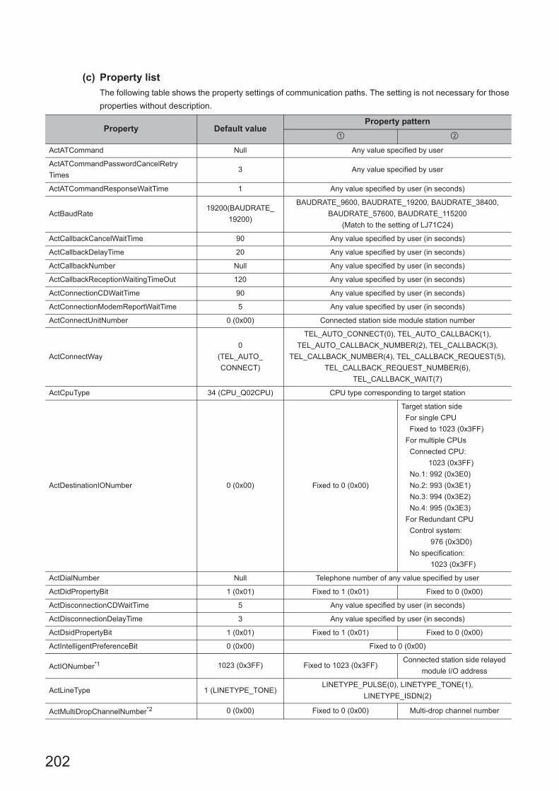
202
(c) Property list
The following table shows the property settings of communication paths. The setting is not necessary for those
properties without description.
Property Default valueProperty pattern
ActATCommand Null Any value specified by user
ActATCommandPasswordCancelRetry
Times3 Any value specified by user
ActATCommandResponseWaitTime 1 Any value specified by user (in seconds)
ActBaudRate19200(BAUDRATE_
19200)
BAUDRATE_9600, BAUDRATE_19200, BAUDRATE_38400,
BAUDRATE_57600, BAUDRATE_115200
(Match to the setting of LJ71C24)
ActCallbackCancelWaitTime 90 Any value specified by user (in seconds)
ActCallbackDelayTime 20 Any value specified by user (in seconds)
ActCallbackNumber Null Any value specified by user (in seconds)
ActCallbackReceptionWaitingTimeOut 120 Any value specified by user (in seconds)
ActConnectionCDWaitTime 90 Any value specified by user (in seconds)
ActConnectionModemReportWaitTime 5 Any value specified by user (in seconds)
ActConnectUnitNumber 0 (0x00) Connected station side module station number
ActConnectWay
0
(TEL_AUTO_
CONNECT)
TEL_AUTO_CONNECT(0), TEL_AUTO_CALLBACK(1),
TEL_AUTO_CALLBACK_NUMBER(2), TEL_CALLBACK(3),
TEL_CALLBACK_NUMBER(4), TEL_CALLBACK_REQUEST(5),
TEL_CALLBACK_REQUEST_NUMBER(6),
TEL_CALLBACK_WAIT(7)
ActCpuType 34 (CPU_Q02CPU) CPU type corresponding to target station
ActDestinationIONumber 0 (0x00) Fixed to 0 (0x00)
Target station side
For single CPU
Fixed to 1023 (0x3FF)
For multiple CPUs
Connected CPU:
1023 (0x3FF)
No.1: 992 (0x3E0)
No.2: 993 (0x3E1)
No.3: 994 (0x3E2)
No.4: 995 (0x3E3)
For Redundant CPU
Control system:
976 (0x3D0)
No specification:
1023 (0x3FF)
ActDialNumber Null Telephone number of any value specified by user
ActDidPropertyBit 1 (0x01) Fixed to 1 (0x01) Fixed to 0 (0x00)
ActDisconnectionCDWaitTime 5 Any value specified by user (in seconds)
ActDisconnectionDelayTime 3 Any value specified by user (in seconds)
ActDsidPropertyBit 1 (0x01) Fixed to 1 (0x01) Fixed to 0 (0x00)
ActIntelligentPreferenceBit 0 (0x00) Fixed to 0 (0x00)
ActIONumber*1 1023 (0x3FF) Fixed to 1023 (0x3FF)Connected station side relayed
module I/O address
ActLineType 1 (LINETYPE_TONE)LINETYPE_PULSE(0), LINETYPE_TONE(1),
LINETYPE_ISDN(2)
ActMultiDropChannelNumber*2 0 (0x00) Fixed to 0 (0x00) Multi-drop channel number
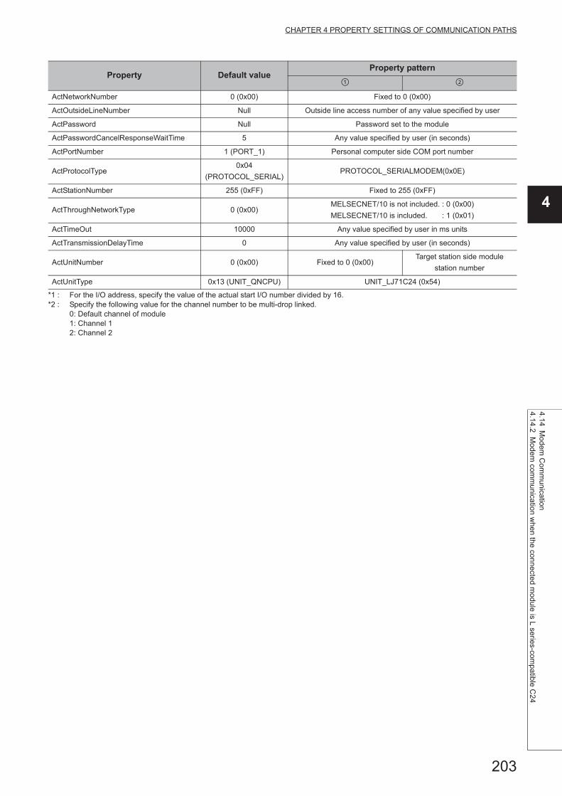
203
CHAPTER 4 PROPERTY SETTINGS OF COMMUNICATION PATHS
4
4.14 Mo
dem C
omm
unication4.14.2 M
odem com
munication w
hen the connected m
odule is L series-compatible C
24
*1 : For the I/O address, specify the value of the actual start I/O number divided by 16.*2 : Specify the following value for the channel number to be multi-drop linked.
0: Default channel of module1: Channel 12: Channel 2
ActNetworkNumber 0 (0x00) Fixed to 0 (0x00)
ActOutsideLineNumber Null Outside line access number of any value specified by user
ActPassword Null Password set to the module
ActPasswordCancelResponseWaitTime 5 Any value specified by user (in seconds)
ActPortNumber 1 (PORT_1) Personal computer side COM port number
ActProtocolType0x04
(PROTOCOL_SERIAL)PROTOCOL_SERIALMODEM(0x0E)
ActStationNumber 255 (0xFF) Fixed to 255 (0xFF)
ActThroughNetworkType 0 (0x00)MELSECNET/10 is not included. : 0 (0x00)
MELSECNET/10 is included. : 1 (0x01)
ActTimeOut 10000 Any value specified by user in ms units
ActTransmissionDelayTime 0 Any value specified by user (in seconds)
ActUnitNumber 0 (0x00) Fixed to 0 (0x00)Target station side module
station number
ActUnitType 0x13 (UNIT_QNCPU) UNIT_LJ71C24 (0x54)
Property Default valueProperty pattern

204
4.14.3 Modem communication when the connected station is FXCPU
(1) Configuration
(2) Property patterns
Connected
station CPURelayed network
Relayed station CPU
FXCPU RCPUR motion
CPU
CC IE Control
CC IE Field
MELSECNET/H
Ethernet
Serial
communication
CC-Link
Connected
station CPU
Relayed network
Relayed station CPU
FXCPUQCPU
(Q mode)
C
Controller
module
LCPU QSCPUQ motion
CPUFXCPU
CC IE Control
CC IE Field
MELSECNET/H
Ethernet
Serial
communication
CC-Link
: Accessible (The number in the circle is the property pattern number.), : Inaccessible
Connected
station CPU
Relayed
module
Relayed network
Relayed
station CPU
Relayed
module
Personal computer
Modem
Subscriber's line
Modem

205
CHAPTER 4 PROPERTY SETTINGS OF COMMUNICATION PATHS
4
4.14 Mo
dem C
omm
unication4.14.3 M
odem com
munication w
hen the connected sta
tion is FX
CP
U
(3) Property listThe following table shows the property settings of communication paths. The setting is not necessary for those
properties without description.
Property Default valueProperty pattern
ActATCommand Null Any value specified by user
ActATCommandPasswordCancelRetry
Times3 Any value specified by user
ActATCommandResponseWaitTime 1 Any value specified by user (in seconds)
ActCallbackCancelWaitTime 90 Any value specified by user (in seconds)
ActCallbackDelayTime 20 Any value specified by user (in seconds)
ActCallbackNumber Null Any value specified by user (in seconds)
ActCallbackReceptionWaitingTimeOut 120 Any value specified by user (in seconds)
ActConnectionCDWaitTime 90 Any value specified by user (in seconds)
ActConnectionModemReportWaitTime 5 Any value specified by user (in seconds)
ActCpuType 34 (CPU_Q02CPU) CPU type corresponding to target station
ActDialNumber Null Telephone number of any value specified by user
ActDisconnectionCDWaitTime 5 Any value specified by user (in seconds)
ActDisconnectionDelayTime 3 Any value specified by user (in seconds)
ActLineType 1 (LINETYPE_TONE)LINETYPE_PULSE(0), LINETYPE_TONE(1),
LINETYPE_ISDN(2)
ActOutsideLineNumber NullOutside line access number of any value specified
by user
ActPasswordCancelResponseWaitTime 5 Any value specified by user (in seconds)
ActPortNumber 1 (PORT_1) Personal computer side COM port number
ActProtocolType0x04
(PROTOCOL_SERIAL)PROTOCOL_TEL (0x0A)
ActTimeOut 10000 Any value specified by user in ms units
ActTransmissionDelayTime 0 Any value specified by user (in seconds)
ActUnitType 0x13 (UNIT_QNCPU) UNIT_FXCPU (0x0F)

206
4.15 Gateway Function Communication
(1) Configuration
(2) Property listThe following table shows the property settings of communication paths. The setting is not necessary for those
properties without description.
Property Default valueProperty pattern
ActHostAddress 1.1.1.1 Host name or IP address of connected GOT
ActPortNumber 1 (PORT_1) Personal computer side port number
ActProtocolType0x04
(PROTOCOL_SERIAL)PROTOCOL_UDPIP (0x08)
ActTimeOut 10000 Any value specified by user in ms units
ActUnitType 0x13 (UNIT_QNCPU) UNIT_A900GOT (0x21)
GOT
Personal computer

207
CHAPTER 4 PROPERTY SETTINGS OF COMMUNICATION PATHS
4
4.16 GO
T T
ransparent F
unction Com
munication
4.16 GOT Transparent Function Communication
For the applicable system configuration, refer to the following manual. • Connection manuals for GOT2000 series
(Mitsubishi Products), (Non-Mitsubishi Products 1), (Non-Mitsubishi Products 2),(Microcomputer, MODBUS Products,Peripherals)
• Connection manuals for GOT1000 series(Mitsubishi Products), (Non-Mitsubishi Products 1), (Non-Mitsubishi Products 2),(Microcomputer, MODBUS Products,Peripherals)
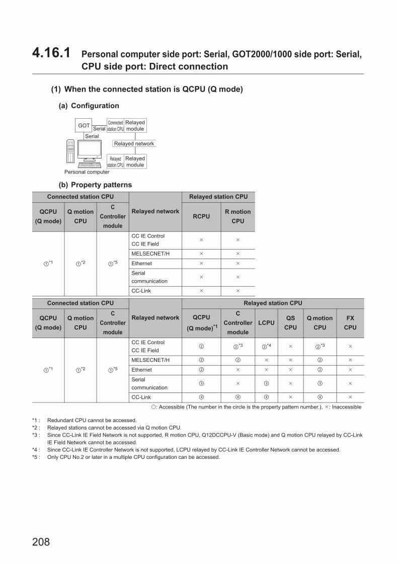
208
4.16.1 Personal computer side port: Serial, GOT2000/1000 side port: Serial, CPU side port: Direct connection
(1) When the connected station is QCPU (Q mode)
(a) Configuration
(b) Property patterns
*1 : Redundant CPU cannot be accessed.*2 : Relayed stations cannot be accessed via Q motion CPU.*3 : Since CC-Link IE Field Network is not supported, R motion CPU, Q12DCCPU-V (Basic mode) and Q motion CPU relayed by CC-Link
IE Field Network cannot be accessed.*4 : Since CC-Link IE Controller Network is not supported, LCPU relayed by CC-Link IE Controller Network cannot be accessed.*5 : Only CPU No.2 or later in a multiple CPU configuration can be accessed.
Connected station CPU
Relayed network
Relayed station CPU
QCPU
(Q mode)
Q motion
CPU
C
Controller
module
RCPUR motion
CPU
*1 *2 *5
CC IE Control
CC IE Field
MELSECNET/H
Ethernet
Serial
communication
CC-Link
Connected station CPU
Relayed network
Relayed station CPU
QCPU
(Q mode)
Q motion
CPU
C
Controller
module
QCPU
(Q mode)*1
C
Controller
module
LCPUQS
CPU
Q motion
CPU
FX
CPU
*1 *2 *5
CC IE Control
CC IE Field *3 *4 *3
MELSECNET/H
Ethernet
Serial
communication
CC-Link
: Accessible (The number in the circle is the property pattern number.), : Inaccessible
Personal computer
Connected
station CPU
Relayed
module
Relayed network
Relayed
station CPU
Relayed
module
Serial
SerialGOT

209
CHAPTER 4 PROPERTY SETTINGS OF COMMUNICATION PATHS
4
4.16 GO
T T
ransparent F
unction Com
munication
4.16.1 Pe
rsonal compute
r side port: S
erial, GO
T2000/1000 side port: S
erial, CP
U side port: D
irect connection
(c) Property list
The following table shows the property settings of communication paths. The setting is not necessary for those
properties without description.
Property Default valueProperty pattern
ActBaudRate
19200
(BAUDRATE_
19200)
BAUDRATE_9600, BAUDRATE_19200, BAUDRATE_38400, BAUDRATE_57600,
BAUDRATE_115200
ActCpuType34
(CPU_Q02CPU)CPU type corresponding to target station
ActDestination
IONumber0 (0x00) Fixed to 0 (0x00) Fixed to 0 (0x00)
Target station side
For single CPU
Fixed to
1023 (0x3FF)
For multiple CPUs
Connected CPU:
1023 (0x3FF)
No.1: 992 (0x3E0)
No.2: 993 (0x3E1)
No.3: 994 (0x3E2)
No.4: 995 (0x3E3)
Target station side
For single CPU
Fixed to
1023 (0x3FF)
For multiple CPUs
Connected CPU:
1023 (0x3FF)
No.1: 992 (0x3E0)
No.2: 993 (0x3E1)
No.3: 994 (0x3E2)
No.4: 995 (0x3E3)
ActDidProperty
Bit1 (0x01) Fixed to 1 (0x01) Fixed to 1 (0x01) Fixed to 0 (0x00) Fixed to 0 (0x00)
ActDsidProperty
Bit1 (0x01) Fixed to 1 (0x01) Fixed to 1 (0x01) Fixed to 0 (0x00) Fixed to 0 (0x00)
ActIntelligent
PreferenceBit0 (0x00) Fixed to 0 (0x00) Fixed to 0 (0x00)
Target station
QCPU (Q mode),
C Controller module,
LCPU : 1 (0x01)
Other than the above
: 0 (0x00)
Target station
QCPU (Q mode),
C Controller module,
LCPU : 1 (0x01)
Other than the above
: 0 (0x00)
ActIONumber*1 1023 (0x3FF)
For single CPU
Fixed to
1023 (0x3FF)
For multiple CPUs
Connected CPU:
1023 (0x3FF)
No.1: 992 (0x3E0)
No.2: 993 (0x3E1)
No.3: 994 (0x3E2)
No.4: 995 (0x3E3)
Target station side
For single CPU
Fixed to
1023 (0x3FF)
For multiple CPUs
Connected CPU:
1023 (0x3FF)
No.1: 992 (0x3E0)
No.2: 993 (0x3E1)
No.3: 994 (0x3E2)
No.4: 995 (0x3E3)
Connected station
side module I/O
address
Connected station
side module I/O
address
ActMultiDrop
ChannelNumber*20 (0x00) Fixed to 0 (0x00) Fixed to 0 (0x00)
Multi-drop channel
numberFixed to 0 (0x00)
ActNetwork
Number0 (0x00) Fixed to 0 (0x00)
Target station side
module network
number
Fixed to 0 (0x00) Fixed to 0 (0x00)
ActPortNumber 1 (PORT_1) Personal computer side COM port number
ActProtocolType
0x04
(PROTOCOL_
SERIAL)
PROTOCOL_SERIAL (0x04)
ActStation
Number255 (0xFF) Fixed to 255 (0xFF)
Target station side
module station
number
Fixed to 255 (0xFF) Fixed to 255 (0xFF)

210
*1 : For the I/O address, specify the value of the actual start I/O number divided by 16.*2 : Specify the following value for the channel number to be multi-drop linked.
0: Default channel of module1: Channel 12: Channel 2
ActThrough
NetworkType0 (0x00)
MELSECNET/10 is not included. : 0 (0x00)
MELSECNET/10 is included. : 1 (0x01)
ActTimeOut 10000 Any value specified by user in ms units
ActUnitNumber 0 (0x00) Fixed to 0 (0x00) Fixed to 0 (0x00)
Target station side
module station
number
Target station side
module station
number
ActUnitType0x13
(UNIT_QNCPU)UNIT_QNCPU (0x13)
Property Default valueProperty pattern
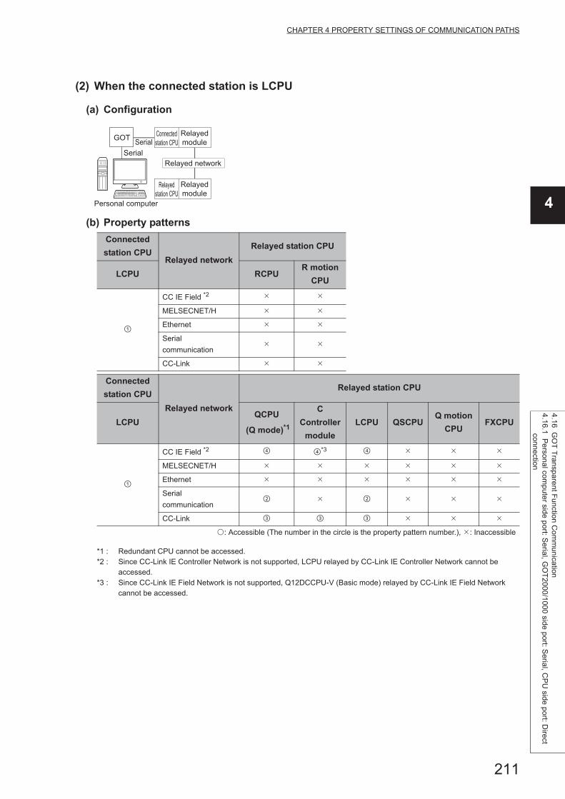
211
CHAPTER 4 PROPERTY SETTINGS OF COMMUNICATION PATHS
4
4.16 GO
T T
ransparent F
unction Com
munication
4.16.1 Pe
rsonal compute
r side port: S
erial, GO
T2000/1000 side port: S
erial, CP
U side port: D
irect connection
(2) When the connected station is LCPU
(a) Configuration
(b) Property patterns
*1 : Redundant CPU cannot be accessed.*2 : Since CC-Link IE Controller Network is not supported, LCPU relayed by CC-Link IE Controller Network cannot be
accessed.*3 : Since CC-Link IE Field Network is not supported, Q12DCCPU-V (Basic mode) relayed by CC-Link IE Field Network
cannot be accessed.
Connected
station CPURelayed network
Relayed station CPU
LCPU RCPUR motion
CPU
CC IE Field *2
MELSECNET/H
Ethernet
Serial
communication
CC-Link
Connected
station CPU
Relayed network
Relayed station CPU
LCPUQCPU
(Q mode)*1
C
Controller
module
LCPU QSCPUQ motion
CPUFXCPU
CC IE Field *2 *3
MELSECNET/H
Ethernet
Serial
communication
CC-Link
: Accessible (The number in the circle is the property pattern number.), : Inaccessible
Personal computer
Connected
station CPU
Relayed
module
Relayed network
Relayed
station CPU
Relayed
module
Serial
SerialGOT

212
(c) Property list
The following table shows the property settings of communication paths. The setting is not necessary for those
properties without description.
Property Default valueProperty pattern
ActBaudRate
19200
(BAUDRATE_
19200)
BAUDRATE_9600, BAUDRATE_19200, BAUDRATE_38400, BAUDRATE_57600,
BAUDRATE_115200
ActControl8 (TRC_DTR
_OR_RTS)8 (TRC_DTR_OR_RTS)
ActCpuType34
(CPU_Q02CPU)CPU type corresponding to target station
ActDestination
IONumber0 (0x00) Fixed to 0 (0x00)
Target station side
For single CPU
Fixed to
1023 (0x3FF)
For multiple CPUs
Connected CPU:
1023 (0x3FF)
No.1: 992 (0x3E0)
No.2: 993 (0x3E1)
No.3: 994 (0x3E2)
No.4: 995 (0x3E3)
Target station side
For single CPU
Fixed to
1023 (0x3FF)
For multiple CPUs
Connected CPU:
1023 (0x3FF)
No.1: 992 (0x3E0)
No.2: 993 (0x3E1)
No.3: 994 (0x3E2)
No.4: 995 (0x3E3)
Fixed to 0 (0x00)
ActDidPropertyBit 1 (0x01) Fixed to 1 (0x01) Fixed to 0 (0x00) Fixed to 0 (0x00) Fixed to 1 (0x01)
ActDsidPropertyBit 1 (0x01) Fixed to 1 (0x01) Fixed to 0 (0x00) Fixed to 0 (0x00) Fixed to 1 (0x01)
ActIntelligent
PreferenceBit0 (0x00) Fixed to 0 (0x00)
Target station
QCPU (Q mode),
C Controller module,
LCPU : 1 (0x01)
Other than the above
: 0 (0x00)
Target station
QCPU (Q mode),
C Controller module,
LCPU : 1 (0x01)
Other than the above
: 0 (0x00)
Fixed to 0 (0x00)
ActIONumber*1 1023 (0x3FF)Fixed to 1023
(0x3FF)
Connected station side
module I/O address
Connected station side
module I/O address
Target station side
For single CPU
Fixed to
1023 (0x3FF)
For multiple CPUs
Connected CPU:
1023 (0x3FF)
No.1: 992 (0x3E0)
No.2: 993 (0x3E1)
No.3: 994 (0x3E2)
No.4: 995 (0x3E3)
ActMultiDrop
ChannelNumber*20 (0x00) Fixed to 0 (0x00)
Multi-drop channel
numberFixed to 0 (0x00) Fixed to 0 (0x00)
ActNetworkNumber 0 (0x00) Fixed to 0 (0x00) Fixed to 0 (0x00) Fixed to 0 (0x00)
Target station side
module network
number
ActPortNumber 1 (PORT_1) Personal computer side COM port number
ActProtocolType
0x04
(PROTOCOL_
SERIAL)
PROTOCOL_SERIAL (0x04)
ActStationNumber 255 (0xFF)Fixed to 255
(0xFF)Fixed to 255 (0xFF) Fixed to 255 (0xFF)
Target station side
module station number

213
CHAPTER 4 PROPERTY SETTINGS OF COMMUNICATION PATHS
4
4.16 GO
T T
ransparent F
unction Com
munication
4.16.1 Pe
rsonal compute
r side port: S
erial, GO
T2000/1000 side port: S
erial, CP
U side port: D
irect connection
*1 : For the I/O address, specify the value of the actual start I/O number divided by 16.*2 : Specify the following value for the channel number to be multi-drop linked.
0: Default channel of module1: Channel 12: Channel 2
ActThroughNetwork
Type0 (0x00)
MELSECNET/10 is not included. : 0 (0x00)
MELSECNET/10 is included. : 1 (0x01)
ActTimeOut 10000 Any value specified by user in ms units
ActUnitNumber 0 (0x00) Fixed to 0 (0x00)Target station side
module station number
Target station side
module station numberFixed to 0 (0x00)
ActUnitType0x13
(UNIT_QNCPU)UNIT_LNCPU (0x50)
Property Default valueProperty pattern

214
(3) When the connected station is FXCPU
(a) Configuration
(b) Property patterns
*1 : Only FX3G(C)CPU and FX3U(C)CPU can be accessed.
Connected
station CPURelayed network
Relayed station CPU
FXCPU RCPUR motion
CPU
CC IE Control
CC IE Field
MELSECNET/H
Ethernet
Serial
communication
CC-Link
Connected
station CPU
Relayed network
Relayed station CPU
FXCPUQCPU
(Q mode)
C
Controller
module
LCPU QSCPUQ motion
CPUFXCPU
CC IE Control
CC IE Field
MELSECNET/H
Ethernet
Serial
communication
CC-Link *1
: Accessible (The number in the circle is the property pattern number.), : Inaccessible
Personal computer
Connected
station CPU
Relayed
module
Relayed network
Relayed
station CPU
Relayed
module
Serial
SerialGOT
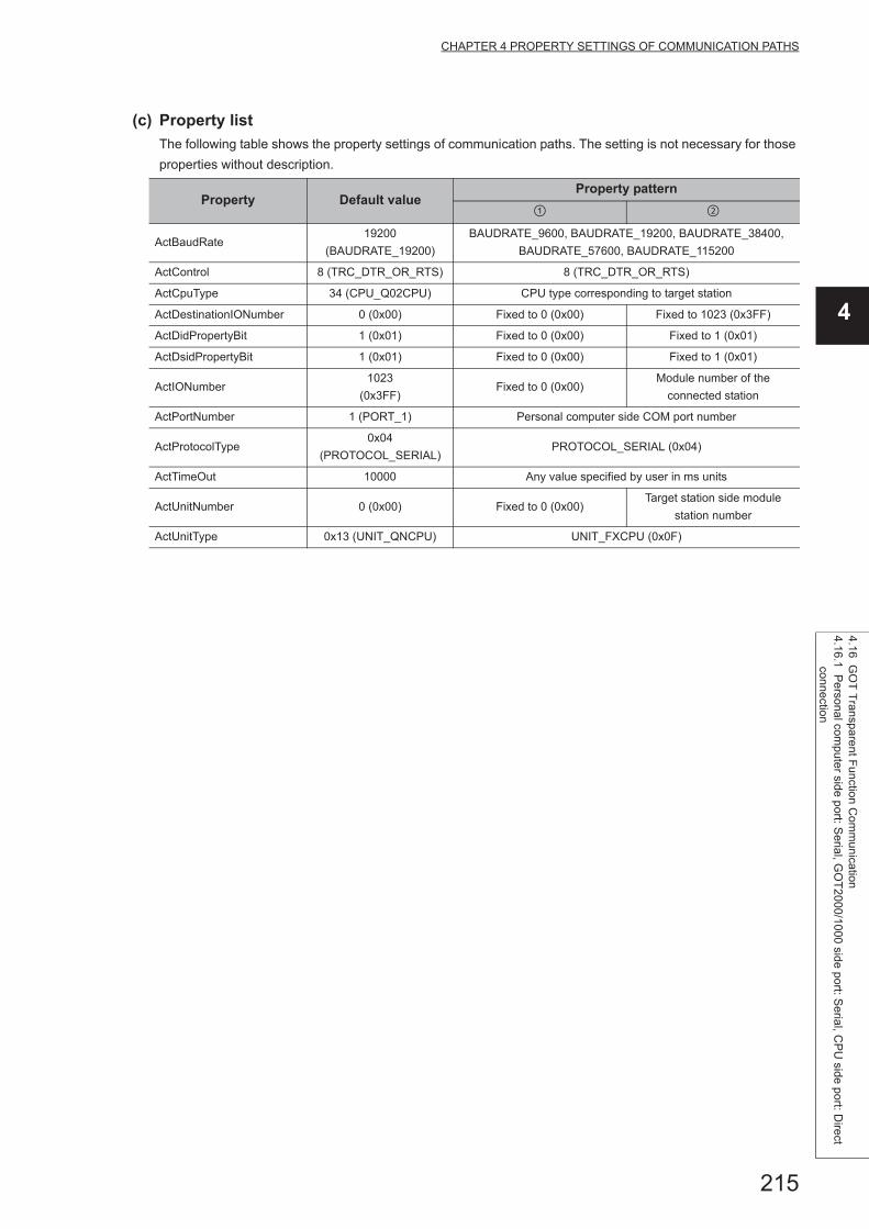
215
CHAPTER 4 PROPERTY SETTINGS OF COMMUNICATION PATHS
4
4.16 GO
T T
ransparent F
unction Com
munication
4.16.1 Pe
rsonal compute
r side port: S
erial, GO
T2000/1000 side port: S
erial, CP
U side port: D
irect connection
(c) Property list
The following table shows the property settings of communication paths. The setting is not necessary for those
properties without description.
Property Default valueProperty pattern
ActBaudRate19200
(BAUDRATE_19200)
BAUDRATE_9600, BAUDRATE_19200, BAUDRATE_38400,
BAUDRATE_57600, BAUDRATE_115200
ActControl 8 (TRC_DTR_OR_RTS) 8 (TRC_DTR_OR_RTS)
ActCpuType 34 (CPU_Q02CPU) CPU type corresponding to target station
ActDestinationIONumber 0 (0x00) Fixed to 0 (0x00) Fixed to 1023 (0x3FF)
ActDidPropertyBit 1 (0x01) Fixed to 0 (0x00) Fixed to 1 (0x01)
ActDsidPropertyBit 1 (0x01) Fixed to 0 (0x00) Fixed to 1 (0x01)
ActIONumber1023
(0x3FF)Fixed to 0 (0x00)
Module number of the
connected station
ActPortNumber 1 (PORT_1) Personal computer side COM port number
ActProtocolType0x04
(PROTOCOL_SERIAL)PROTOCOL_SERIAL (0x04)
ActTimeOut 10000 Any value specified by user in ms units
ActUnitNumber 0 (0x00) Fixed to 0 (0x00)Target station side module
station number
ActUnitType 0x13 (UNIT_QNCPU) UNIT_FXCPU (0x0F)

216
4.16.2 Personal computer side port: USB, GOT2000/1000 side port: USB, CPU side port: Direct connection
(1) When the connected station is QCPU (Q mode)
(a) Configuration
(b) Property patterns
*1 : Redundant CPU cannot be accessed.*2 : Relayed stations cannot be accessed via Q motion CPU.*3 : Since CC-Link IE Field Network is not supported, R motion CPU, Q12DCCPU-V (Basic mode) and Q motion CPU relayed by CC-Link
IE Field Network cannot be accessed.*4 : Since CC-Link IE Controller Network is not supported, LCPU relayed by CC-Link IE Controller Network cannot be accessed.*5 : Only CPU No.2 or later in a multiple CPU configuration can be accessed.
Connected station CPU
Relayed
network
Relayed station CPU
QCPU
(Q mode)
Q motion
CPU
C
Controller
module
RCPUR motion
CPU
*1 *2 *5
CC IE Control
CC IE Field
MELSECNET/H
Ethernet
Serial
communication
CC-Link
Connected station CPU
Relayed
network
Relayed station CPU
QCPU
(Q mode)
Q motion
CPU
C
Controller
module
QCPU
(Q mode)*1
C
Controller
module
LCPUQS
CPU
Q motion
CPU
FX
CPU
*1 *2 *5
CC IE Control
CC IE Field *3 *4 *3
MELSECNET/H
Ethernet
Serial
communication
CC-Link
: Accessible (The number in the circle is the property pattern number.), : Inaccessible
Personal computer
Connected
station CPU
Relayed
module
Relayed network
Relayed
station CPU
Relayed
module
USB
SerialGOT

217
CHAPTER 4 PROPERTY SETTINGS OF COMMUNICATION PATHS
4
4.16 GO
T T
ransparent F
unction Com
munication
4.16.2 Pe
rsonal compute
r side port: U
SB
, GO
T2000/1
000 side port: U
SB
, CP
U side port: D
irect connection
(c) Property list
The following table shows the property settings of communication paths. The setting is not necessary for those
properties without description.
Property Default valueProperty pattern
ActCpuType34
(CPU_Q02CPU)CPU type corresponding to target station
ActDestination
IONumber0 (0x00) Fixed to 0 (0x00) Fixed to 0 (0x00)
Target station side
For single CPU
Fixed to
1023 (0x3FF)
For multiple CPUs
Connected CPU:
1023 (0x3FF)
No.1: 992 (0x3E0)
No.2: 993 (0x3E1)
No.3: 994 (0x3E2)
No.4: 995 (0x3E3)
Target station side
For single CPU
Fixed to
1023 (0x3FF)
For multiple CPUs
Connected CPU:
1023 (0x3FF)
No.1: 992 (0x3E0)
No.2: 993 (0x3E1)
No.3: 994 (0x3E2)
No.4: 995 (0x3E3)
ActDidProperty
Bit1 (0x01) Fixed to 1 (0x01) Fixed to 1 (0x01) Fixed to 0 (0x00) Fixed to 0 (0x00)
ActDsidProperty
Bit1 (0x01) Fixed to 1 (0x01) Fixed to 1 (0x01) Fixed to 0 (0x00) Fixed to 0 (0x00)
ActIntelligent
PreferenceBit0 (0x00) Fixed to 0 (0x00) Fixed to 0 (0x00)
Target station
QCPU (Q mode),
C Controller module,
LCPU : 1 (0x01)
Other than the above
: 0 (0x00)
Target station
QCPU (Q mode),
C Controller module,
LCPU : 1 (0x01)
Other than the above
: 0 (0x00)
ActIONumber*1 1023 (0x3FF)
Target station side
For single CPU
Fixed to
1023 (0x3FF)
For multiple CPUs
Connected CPU:
1023 (0x3FF)
No.1: 992 (0x3E0)
No.2: 993 (0x3E1)
No.3: 994 (0x3E2)
No.4: 995 (0x3E3)
Target station side
For single CPU
Fixed to
1023 (0x3FF)
For multiple CPUs
Connected CPU:
1023 (0x3FF)
No.1: 992 (0x3E0)
No.2: 993 (0x3E1)
No.3: 994 (0x3E2)
No.4: 995 (0x3E3)
Connected station
side module I/O
address
Connected station
side module I/O
address
ActMultiDrop
ChannelNumber*20 (0x00) Fixed to 0 (0x00) Fixed to 0 (0x00)
Multi-drop channel
numberFixed to 0 (0x00)
ActNetwork
Number0 (0x00) Fixed to 0 (0x00)
Target station side
module station
number
Fixed to 0 (0x00) Fixed to 0 (0x00)
ActProtocolType
0x04
(PROTOCOL_
SERIAL)
PROTOCOL_USBGOT (0x13)
ActStation
Number255 (0xFF) Fixed to 255 (0xFF)
Target station side
module station
number
Fixed to 255 (0xFF) Fixed to 255 (0xFF)
ActThrough
NetworkType0 (0x00)
MELSECNET/10 is not included. : 0 (0x00)
MELSECNET/10 is included. : 1 (0x01)
ActTimeOut 10000 Any value specified by user in ms units

218
*1 : For the I/O address, specify the value of the actual start I/O number divided by 16.*2 : Specify the following value for the channel number to be multi-drop linked.
0: Default channel of module1: Channel 12: Channel 2
ActUnitNumber 0 (0x00) Fixed to 0 (0x00) Fixed to 0 (0x00)
Target station side
module station
number
Target station side
module station
number
ActUnitType0x13
(UNIT_QNCPU)UNIT_QNCPU (0x13)
Property Default valueProperty pattern

219
CHAPTER 4 PROPERTY SETTINGS OF COMMUNICATION PATHS
4
4.16 GO
T T
ransparent F
unction Com
munication
4.16.2 Pe
rsonal compute
r side port: U
SB
, GO
T2000/1
000 side port: U
SB
, CP
U side port: D
irect connection
(2) When the connected station is LCPU
(a) Configuration
(b) Property patterns
*1 : Redundant CPU cannot be accessed.*2 : Since CC-Link IE Controller Network is not supported, LCPU relayed by CC-Link IE Controller Network cannot be
accessed.*3 : Since CC-Link IE Field Network is not supported, Q12DCCPU-V (Basic mode) relayed by CC-Link IE Field Network
cannot be accessed.
Connected
station CPURelayed network
Relayed station CPU
LCPU RCPUR motion
CPU
CC IE Field *2
MELSECNET/H
Ethernet
Serial
communication
CC-Link
Connected
station CPU
Relayed network
Relayed station CPU
LCPUQCPU
(Q mode)*1
C
Controller
module
LCPU QSCPUQ motion
CPUFXCPU
CC IE Field *2 *3
MELSECNET/H
Ethernet
Serial
communication
CC-Link
: Accessible (The number in the circle is the property pattern number.), : Inaccessible
Personal computer
Connected
station CPU
Relayed
module
Relayed network
Relayed
station CPU
Relayed
module
USB
SerialGOT

220
(c) Property list
The following table shows the property settings of communication paths. The setting is not necessary for those
properties without description.
Property Default valueProperty pattern
ActCpuType34
(CPU_Q02CPU)CPU type corresponding to target station
ActDestination
IONumber0 (0x00) Fixed to 0 (0x00)
Target station side
For single CPU
Fixed to
1023 (0x3FF)
For multiple CPUs
Connected CPU:
1023 (0x3FF)
No.1: 992 (0x3E0)
No.2: 993 (0x3E1)
No.3: 994 (0x3E2)
No.4: 995 (0x3E3)
Target station side
For single CPU
Fixed to
1023 (0x3FF)
For multiple CPUs
Connected CPU:
1023 (0x3FF)
No.1: 992 (0x3E0)
No.2: 993 (0x3E1)
No.3: 994 (0x3E2)
No.4: 995 (0x3E3)
Fixed to 0 (0x00)
ActDidPropertyBit 1 (0x01) Fixed to 1 (0x01) Fixed to 0 (0x00) Fixed to 0 (0x00) Fixed to 1 (0x01)
ActDsidPropertyBit 1 (0x01) Fixed to 1 (0x01) Fixed to 0 (0x00) Fixed to 0 (0x00) Fixed to 1 (0x01)
ActIntelligent
PreferenceBit0 (0x00) Fixed to 0 (0x00)
Target station
QCPU (Q mode),
C Controller module,
LCPU : 1 (0x01)
Other than the above
: 0 (0x00)
Target station
QCPU (Q mode),
C Controller module,
LCPU : 1 (0x01)
Other than the above
: 0 (0x00)
Fixed to 0 (0x00)
ActIONumber*1 1023 (0x3FF)Fixed to 1023
(0x3FF)
Connected station side
module I/O address
Connected station side
module I/O address
Target station side
For single CPU
Fixed to
1023 (0x3FF)
For multiple CPUs
Connected CPU:
1023 (0x3FF)
No.1: 992 (0x3E0)
No.2: 993 (0x3E1)
No.3: 994 (0x3E2)
No.4: 995 (0x3E3)
ActMultiDrop
ChannelNumber*20 (0x00) Fixed to 0 (0x00)
Multi-drop channel
numberFixed to 0 (0x00) Fixed to 0 (0x00)
ActNetworkNumber 0 (0x00) Fixed to 0 (0x00) Fixed to 0 (0x00) Fixed to 0 (0x00)
Target station side
module network
number
ActProtocolType
0x04
(PROTOCOL_
SERIAL)
PROTOCOL_USBGOT (0x13)
ActStationNumber 255 (0xFF)Fixed to 255
(0xFF)Fixed to 255 (0xFF) Fixed to 255 (0xFF)
Target station side
module station number
ActThroughNetwork
Type0 (0x00)
MELSECNET/10 is not included. : 0 (0x00)
MELSECNET/10 is included. : 1 (0x01)
ActTimeOut 10000 Any value specified by user in ms units
ActUnitNumber 0 (0x00) Fixed to 0 (0x00)Target station side
module station number
Target station side
module station numberFixed to 0 (0x00)

221
CHAPTER 4 PROPERTY SETTINGS OF COMMUNICATION PATHS
4
4.16 GO
T T
ransparent F
unction Com
munication
4.16.2 Pe
rsonal compute
r side port: U
SB
, GO
T2000/1
000 side port: U
SB
, CP
U side port: D
irect connection
*1 : For the I/O address, specify the value of the actual start I/O number divided by 16.*2 : Specify the following value for the channel number to be multi-drop linked.
0: Default channel of module1: Channel 12: Channel 2
ActUnitType0x13
(UNIT_QNCPU)UNIT_LNCPU (0x50)
Property Default valueProperty pattern

222
(3) When the connected station is FXCPU
(a) Configuration
(b) Property patterns
*1 : Only FX3G(C)CPU and FX3U(C)CPU can be accessed.
Connected
station CPURelayed network
Relayed station CPU
FXCPU RCPUR motion
CPU
CC IE Control
CC IE Field
MELSECNET/H
Ethernet
Serial
communication
CC-Link
Connected
station CPU
Relayed network
Relayed station CPU
FXCPUQCPU
(Q mode)
C
Controller
module
LCPU QSCPUQ motion
CPUFXCPU
CC IE Control
CC IE Field
MELSECNET/H
Ethernet
Serial
communication
CC-Link *1
: Accessible (The number in the circle is the property pattern number.), : Inaccessible
Personal computer
Connected
station CPU
Relayed
module
Relayed network
Relayed
station CPU
Relayed
module
USB
SerialGOT

223
CHAPTER 4 PROPERTY SETTINGS OF COMMUNICATION PATHS
4
4.16 GO
T T
ransparent F
unction Com
munication
4.16.2 Pe
rsonal compute
r side port: U
SB
, GO
T2000/1
000 side port: U
SB
, CP
U side port: D
irect connection
(c) Property list
The following table shows the property settings of communication paths. The setting is not necessary for those
properties without description.
Property Default valueProperty pattern
ActCpuType 34 (CPU_Q02CPU) CPU type corresponding to target station
ActDestinationIONumber 0 (0x00) 0 (0x00) Fixed to 1023 (0x3FF)
ActDidPropertyBit 1 (0x01) 0 (0x00) Fixed to 1 (0x01)
ActDsidPropertyBit 1 (0x01) 0 (0x00) Fixed to 1 (0x01)
ActIONumber1023
(0x3FF)0 (0x00)
Module number of the
connected station
ActProtocolType0x04
(PROTOCOL_SERIAL)PROTOCOL_USBGOT (0x13)
ActTimeOut 10000 Any value specified by user in ms units
ActUnitNumber 0 (0x00) 0 (0x00)Target station side module
station number
ActUnitType 0x13 (UNIT_QNCPU) UNIT_FXCPU (0x0F)

224
4.16.3 Personal computer side port: Serial, GOT2000/1000 side port: Serial, CPU side port: Bus connection
(1) Configuration
(2) Property patterns
Connected station CPU
Relayed network
Relayed station CPU
QCPU
(Q mode)
Q motion
CPURCPU
R motion
CPU
*1 *2,*5
CC IE Control
CC IE Field
MELSECNET/H
Ethernet
Serial
communication
CC-Link
Connected station CPU
Relayed network
Relayed station CPU
QCPU
(Q mode)
Q motion
CPU
QCPU
(Q mode)*1
C
Controller
module
LCPUQS
CPU
Q motion
CPU
FX
CPU
*1 *2,*5
CC IE Control
CC IE Field *3 *4 *3
MELSECNET/H
Ethernet
Serial
communication
CC-Link
Personal computer
Relayed network
Relayed
station CPU
Relayed
module
Serial
Connected
station CPU
Relayed
moduleGOT
Bus

225
CHAPTER 4 PROPERTY SETTINGS OF COMMUNICATION PATHS
4
4.16 GO
T T
ransparent F
unction Com
munication
4.16.3 Pe
rsonal compute
r side port: S
erial, GO
T2000/1000 side port: S
erial, CP
U side port: B
us connection
*1 : Redundant CPU cannot be accessed.*2 : Relayed stations cannot be accessed via Q motion CPU.*3 : Since CC-Link IE Field Network is not supported, Q12DCCPU-V (Basic mode) and Q motion CPU relayed by CC-Link IE Field Network
cannot be accessed.*4 : Since CC-Link IE Controller Network is not supported, LCPU relayed by CC-Link IE Controller Network cannot be accessed.*5 : Only CPU No.2 or later in a multiple CPU configuration can be accessed.*6 : Q24DHCCPU-V and Q24DHCCPU-LS cannot be accessed because the communication route is not supported.
Connected station CPU
Relayed network
Relayed station CPU
C Controller module RCPUR motion
CPU
*6
CC IE Control
CC IE Field
MELSECNET/H
Ethernet
Serial
communication
CC-Link
Connected station CPU
Relayed network
Relayed station CPU
C Controller moduleQCPU
(Q mode)*1
C
Controller
module
LCPUQS
CPU
Q motion
CPU
FX
CPU
*6
CC IE Control
CC IE Field *3 *4 *3
MELSECNET/H
Ethernet
Serial
communication
CC-Link
: Accessible (The number in the circle is the property pattern number.), : Inaccessible

226
(3) Property listThe following table shows the property settings of communication paths. The setting is not necessary for those
properties without description.
Property Default valueProperty pattern
ActBaudRate
19200
(BAUDRATE_
19200)
BAUDRATE_9600, BAUDRATE_19200, BAUDRATE_38400, BAUDRATE_57600,
BAUDRATE_115200
ActCpuType34
(CPU_Q02CPU)CPU type corresponding to target station
ActDestination
IONumber0 (0x00) Fixed to 0 (0x00) Fixed to 0 (0x00)
Target station side
For single CPU
Fixed to
1023 (0x3FF)
For multiple CPUs
Connected CPU:
1023 (0x3FF)
No.1: 992 (0x3E0)
No.2: 993 (0x3E1)
No.3: 994 (0x3E2)
No.4: 995 (0x3E3)
Target station side
For single CPU
Fixed to
1023 (0x3FF)
For multiple CPUs
Connected CPU:
1023 (0x3FF)
No.1: 992 (0x3E0)
No.2: 993 (0x3E1)
No.3: 994 (0x3E2)
No.4: 995 (0x3E3)
ActDidProperty
Bit1 (0x01) Fixed to 1 (0x01) Fixed to 1 (0x01) Fixed to 0 (0x00) Fixed to 0 (0x00)
ActDsidProperty
Bit1 (0x01) Fixed to 1 (0x01) Fixed to 1 (0x01) Fixed to 0 (0x00) Fixed to 0 (0x00)
ActIntelligent
PreferenceBit0 (0x00) Fixed to 0 (0x00) Fixed to 0 (0x00)
Target station
QCPU (Q mode),
C Controller module,
LCPU : 1 (0x01)
Other than the above
: 0 (0x00)
Target station
QCPU (Q mode),
C Controller module,
LCPU : 1 (0x01)
Other than the above
: 0 (0x00)
ActIONumber*1 1023 (0x3FF)
Target station side
For single CPU
Fixed to
1023 (0x3FF)
For multiple CPUs
Connected CPU:
1023 (0x3FF)
No.1: 992 (0x3E0)
No.2: 993 (0x3E1)
No.3: 994 (0x3E2)
No.4: 995 (0x3E3)
Target station side
For single CPU
Fixed to
1023 (0x3FF)
For multiple CPUs
Connected CPU:
1023 (0x3FF)
No.1: 992 (0x3E0)
No.2: 993 (0x3E1)
No.3: 994 (0x3E2)
No.4: 995 (0x3E3)
Connected station
side module I/O
address
Connected station
side module I/O
address
ActMultiDrop
ChannelNumber*20 (0x00) Fixed to 0 (0x00) Fixed to 0 (0x00)
Multi-drop channel
numberFixed to 0 (0x00)
ActNetwork
Number0 (0x00) Fixed to 0 (0x00)
Target station side
module network
number
Fixed to 0 (0x00) Fixed to 0 (0x00)
ActPortNumber 1 (PORT_1) Personal computer side COM port number
ActProtocolType
0x04
(PROTOCOL_
SERIAL)
PROTOCOL_SERIAL (0x04)

227
CHAPTER 4 PROPERTY SETTINGS OF COMMUNICATION PATHS
4
4.16 GO
T T
ransparent F
unction Com
munication
4.16.3 Pe
rsonal compute
r side port: S
erial, GO
T2000/1000 side port: S
erial, CP
U side port: B
us connection
*1 : For the I/O address, specify the value of the actual start I/O number divided by 16.*2 : Specify the following value for the channel number to be multi-drop linked.
0: Default channel of module1: Channel 12: Channel 2
*3 : When a value between 0 and 5000 [ms] is specified, the value is fixed to 5000ms. When a value greater than 255000ms is specified, the value is fixed to 255000ms.
ActStation
Number255 (0xFF) Fixed to 255 (0xFF)
Target station side
module station
number
Fixed to 255 (0xFF) Fixed to 255 (0xFF)
ActTimeOut*3 10000 Any value specified by user in ms units
ActUnitNumber 0 (0x00) Fixed to 0 (0x00) Fixed to 0 (0x00)
Target station side
module station
number
Target station side
module station
number
ActUnitType0x13
(UNIT_QNCPU)UNIT_A900GOT (0x21)
Property Default valueProperty pattern

228
4.16.4 Personal computer side port: USB, GOT2000/1000 side port: USB, CPU side port: Bus connection
(1) Configuration
(2) Property patterns
Connected station CPU
Relayed network
Relayed station CPU
QCPU
(Q mode)
Q motion
CPURCPU
R motion
CPU
*1 *2,*5
CC IE Control
CC IE Field
MELSECNET/H
Ethernet
Serial
communication
CC-Link
Connected station CPU
Relayed network
Relayed station CPU
QCPU
(Q mode)
Q motion
CPU
QCPU
(Q mode)*1
C
Controller
module
LCPUQS
CPU
Q motion
CPU
FX
CPU
*1 *2,*5
CC IE Control
CC IE Field *3 *4 *3
MELSECNET/H
Ethernet
Serial
communication
CC-Link
Personal computer
Relayed network
Relayed
station CPU
Relayed
module
USB
Connected
station CPU
Relayed
moduleGOT
Bus

229
CHAPTER 4 PROPERTY SETTINGS OF COMMUNICATION PATHS
4
4.16 GO
T T
ransparent F
unction Com
munication
4.16.4 Pe
rsonal compute
r side port: U
SB
, GO
T2000/1
000 side port: U
SB
, CP
U side port: B
us connection
*1 : Redundant CPU cannot be accessed.*2 : Relayed stations cannot be accessed via Q motion CPU.*3 : Since CC-Link IE Field Network is not supported, Q12DCCPU-V (Basic mode) and Q motion CPU relayed by CC-Link IE Field Network
cannot be accessed.*4 : Since CC-Link IE Controller Network is not supported, LCPU relayed by CC-Link IE Controller Network cannot be accessed.*5 : Only CPU No.2 or later in a multiple CPU configuration can be accessed.
Connected station CPU
Relayed network
Relayed station CPU
C Controller module RCPUR motion
CPU
CC IE Control
CC IE Field
MELSECNET/H
Ethernet
Serial
communication
CC-Link
Connected station CPU
Relayed network
Relayed station CPU
C Controller moduleQCPU
(Q mode)
C
Controller
module
LCPUQS
CPU
Q motion
CPU
FX
CPU
CC IE Control
CC IE Field *3 *4 *3
MELSECNET/H
Ethernet
Serial
communication
CC-Link
: Accessible (The number in the circle is the property pattern number.), : Inaccessible

230
(3) Property listThe following table shows the property settings of communication paths. The setting is not necessary for those
properties without description.
Property Default valueProperty pattern
ActCpuType34
(CPU_Q02CPU)CPU type corresponding to target station
ActDestination
IONumber0 (0x00) Fixed to 0 (0x00) Fixed to 0 (0x00)
Target station side
For single CPU
Fixed to
1023 (0x3FF)
For multiple CPUs
Connected CPU:
1023 (0x3FF)
No.1: 992 (0x3E0)
No.2: 993 (0x3E1)
No.3: 994 (0x3E2)
No.4: 995 (0x3E3)
Target station side
For single CPU
Fixed to
1023 (0x3FF)
For multiple CPUs
Connected CPU:
1023 (0x3FF)
No.1: 992 (0x3E0)
No.2: 993 (0x3E1)
No.3: 994 (0x3E2)
No.4: 995 (0x3E3)
ActDidProperty
Bit1 (0x01) Fixed to 1 (0x01) Fixed to 1 (0x01) Fixed to 0 (0x00) Fixed to 0 (0x00)
ActDsidProperty
Bit1 (0x01) Fixed to 1 (0x01) Fixed to 1 (0x01) Fixed to 0 (0x00) Fixed to 0 (0x00)
ActIntelligent
PreferenceBit0 (0x00) Fixed to 0 (0x00) Fixed to 0 (0x00)
Target station
QCPU (Q mode),
C Controller module,
LCPU : 1 (0x01)
Other than the above
: 0 (0x00)
Target station
QCPU (Q mode),
C Controller module,
LCPU : 1 (0x01)
Other than the above
: 0 (0x00)
ActIONumber*1 1023 (0x3FF)
Target station side
For single CPU
Fixed to
1023 (0x3FF)
For multiple CPUs
Connected CPU:
1023 (0x3FF)
No.1: 992 (0x3E0)
No.2: 993 (0x3E1)
No.3: 994 (0x3E2)
No.4: 995 (0x3E3)
Target station side
For single CPU
Fixed to
1023 (0x3FF)
For multiple CPUs
Connected CPU:
1023 (0x3FF)
No.1: 992 (0x3E0)
No.2: 993 (0x3E1)
No.3: 994 (0x3E2)
No.4: 995 (0x3E3)
Connected station
side module I/O
address
Connected station
side module I/O
address
ActMultiDrop
ChannelNumber*20 (0x00) Fixed to 0 (0x00) Fixed to 0 (0x00)
Multi-drop channel
numberFixed to 0 (0x00)
ActNetwork
Number0 (0x00) Fixed to 0 (0x00)
Target station side
module network
number
Fixed to 0 (0x00) Fixed to 0 (0x00)
ActProtocolType
0x04
(PROTOCOL_
SERIAL)
PROTOCOL_USBGOT (0x13)
ActStation
Number255 (0xFF) Fixed to 255 (0xFF)
Target station side
module station
number
Fixed to 255 (0xFF) Fixed to 255 (0xFF)
ActTimeOut*3 10000 Any value specified by user in ms units

231
CHAPTER 4 PROPERTY SETTINGS OF COMMUNICATION PATHS
4
4.16 GO
T T
ransparent F
unction Com
munication
4.16.4 Pe
rsonal compute
r side port: U
SB
, GO
T2000/1
000 side port: U
SB
, CP
U side port: B
us connection
*1 : For the I/O address, specify the value of the actual start I/O number divided by 16.*2 : Specify the following value for the channel number to be multi-drop linked.
0: Default channel of module1: Channel 12: Channel 2
*3 : When a value between 0 and 5000 [ms] is specified, the value is fixed to 5000ms. When a value greater than 255000ms is specified, the value is fixed to 255000ms.
ActUnitNumber 0 (0x00) Fixed to 0 (0x00) Fixed to 0 (0x00)
Target station side
module station
number
Target station side
module station
number
ActUnitType0x13
(UNIT_QNCPU)UNIT_A900GOT (0x21)
Property Default valueProperty pattern

232
4.16.5 Personal computer side port: Serial, GOT2000/1000 side port: Serial, CPU side port: Serial communication module
(1) When a relayed module other than the connected station side R series-
compatible C24 exists
(a) Configuration
(b) Property patterns
*1 : Relayed stations cannot be accessed via R motion CPU.*2 : Since CC-Link IE Controller Network is not supported, RCPU relayed by CC-Link IE Controller Network cannot be accessed.*3 : Only CPU No.2 or later in a multiple CPU configuration can be accessed.
Connected station CPU
Relayed network
Relayed station CPU
RCPUR motion
CPURCPU
R motion
CPU
*1,*3
CC IE Control
CC IE Field*2
MELSECNET/H
Ethernet
Serial
communication
CC-Link
Connected station CPU
Relayed network
Relayed station CPU
RCPUR motion
CPU
QCPU
(Q mode)
C
Controller
module
LCPUQS
CPU
Q motion
CPU
FX
CPU
*1,*3
CC IE Control
CC IE Field
MELSECNET/H
Ethernet
Serial
communication
CC-Link
: Accessible (The number in the circle is the property pattern number.), : Inaccessible
Personal computer
Connected
station CPU
Relayed
module
Relayed network
Relayed
station CPU
Relayed
module
Serial
R series-
compatible C24GOT

233
CHAPTER 4 PROPERTY SETTINGS OF COMMUNICATION PATHS
4
4.16 GO
T T
ransparent F
unction Com
munication
4.16.5 Pe
rsonal compute
r side port: S
erial, GO
T2000/1000 side port: S
erial, CP
U side port: S
erial com
munica
tion mo
dule
(c) Property list
The following table shows the property settings of communication paths. The setting is not necessary for those
properties without description.
Property Default valueProperty pattern
*1
ActBaudRate
19200
(BAUDRATE_
19200)
Match to the setting of R series-compatible C24.
ActConnectUnit
Number0(0x00) Connected station side module station number
ActControl8 (TRC_DTR
_OR_RTS)Depending on the used cable.
ActCpuType34
(CPU_Q02CPU)CPU type corresponding to target station
ActDestination
IONumber *20 (0x00) Fixed to 0 (0x00) Fixed to 0 (0x00)
Target station side
For single CPU
Fixed to
1023 (0x3FF)
For multiple CPUs
Connected CPU:
1023 (0x3FF)
No.1: 992 (0x3E0)
No.2: 993 (0x3E1)
No.3: 994 (0x3E2)
No.4: 995 (0x3E3)
Target station side
For single CPU
Fixed to
1023 (0x3FF)
For multiple CPUs
Connected CPU:
1023 (0x3FF)
No.1: 992 (0x3E0)
No.2: 993 (0x3E1)
No.3: 994 (0x3E2)
No.4: 995 (0x3E3)
ActDidPropertyBit 1 (0x01) Fixed to 1 (0x01) Fixed to 1 (0x01) Fixed to 0 (0x00) Fixed to 0 (0x00)
ActDsidPropertyBit 1 (0x01) Fixed to 1 (0x01) Fixed to 1 (0x01) Fixed to 0 (0x00) Fixed to 0 (0x00)
ActIntelligent
PreferenceBit0 (0x00) Fixed to 0 (0x00)
ActIONumber *2 1023 (0x3FF)
For single CPU
Fixed to
1023 (0x3FF)
For multiple CPUs
Connected CPU:
1023 (0x3FF)
No.1: 992 (0x3E0)
No.2: 993 (0x3E1)
No.3: 994 (0x3E2)
No.4: 995 (0x3E3)
Target station side
For single CPU
Fixed to
1023 (0x3FF)
For multiple CPUs
Connected CPU:
1023 (0x3FF)
No.1: 992 (0x3E0)
No.2: 993 (0x3E1)
No.3: 994 (0x3E2)
No.4: 995 (0x3E3)
Connected station
side module I/O
address
Connected station
side module I/O
address
ActMultiDrop
ChannelNumber *30 (0x00) Fixed to 0 (0x00) Fixed to 0 (0x00)
Multi-drop channel
numberFixed to 0 (0x00)
ActNetworkNumber 0 (0x00) Fixed to 0 (0x00)
Target station side
module network
number
Fixed to 0 (0x00) Fixed to 0 (0x00)
ActPortNumber 1 (PORT_1) Personal computer side COM port number
ActProtocolType
0x04
(PROTOCOL_
SERIAL)
PROTOCOL_SERIAL
ActPacketType0x01
(PACKET_PLC1)PACKET_PLC1
ActHostAddress 1.1.1.1 Fixed to NULL
ActCpuTimeOut 0(0x00) Fixed to 0 (0x00)

234
*1 : Note the following considerations when accessing via Ethernet module (R series-compatible E71). • For ActNetworkNumber and ActStationNumber, specify the value set in the parameter setting of the target station side R series-
compatible E71. • Set "Station No. IP information" in the parameter setting of R series-compatible E71. When setting the parameter, specify the
setting other than the automatic response system (any of the IP address calculation system, table conversion system, and combined system) for "Station No. IP information system".
*2 : For the I/O address, specify the value of the actual start I/O number divided by 16.*3 : Specify the following value for the channel number to be multi-drop linked.
0: Default channel of module1: Channel 12: Channel 2
ActDataBits 8(DATABIT_8) Fixed to 8 (0x08)
ActParity 1(ODD_PARITY) Fixed to 1 (0x01)
ActStopBits0(STOPBIT_
ONE)Fixed to 0 (0x00)
ActSumCheck0(NO_SUM_
CHECK)Fixed to 0 (0x00)
ActSourceNetwork
Number0(0x00) Fixed to 0 (0x00)
ActSourceStation
Number0(0x00) Fixed to 0 (0x00)
ActDestinationPort
Number0(0x00) Fixed to 0 (0x00)
ActIntelligent
PreferenceBit0(0x00) Fixed to 0 (0x00)
ActStationNumber 255 (0xFF) Fixed to 255 (0xFF)
Target station side
module station
number
Fixed to 255 (0xFF) Fixed to 255 (0xFF)
ActThroughNetwork
Type0 (0x00)
MELSECNET/10 is not included. : 0 (0x00)
MELSECNET/10 is included. : 1 (0x01)
ActTimeOut 10000 Any value specified by user in ms units
ActUnitNumber 0 (0x00) Fixed to 0 (0x00) Fixed to 0 (0x00)
Target station side
module station
number
Target station side
module station
number
ActUnitType0x13
(UNIT_QNCPU)UNIT_RJ71C24
Property Default valueProperty pattern
*1

235
CHAPTER 4 PROPERTY SETTINGS OF COMMUNICATION PATHS
4
4.16 GO
T T
ransparent F
unction Com
munication
4.16.5 Pe
rsonal compute
r side port: S
erial, GO
T2000/1000 side port: S
erial, CP
U side port: S
erial com
munica
tion mo
dule
(2) When performing multi-drop link on the connected station side R series-
compatible C24 with the relayed module
(a) Configuration
(b) Property patterns
*1 : Relayed stations cannot be accessed via R motion CPU.*2 : The independent mode indicates that the parameters are set as follows.
• CH1 side: Operation setting for transmission setting = independent (0), communication protocol setting = 0 • CH2 side: Operation setting for transmission setting = independent (0)
*3 : Redundant CPU cannot be accessed.*4 : Only CPU No.2 or later in a multiple CPU configuration can be accessed.
Connected
station CPU
Relayed network
Relayed station CPU
RCPU,
R motion
CPU *1,*4
RCPUR motion
CPU
Independent
mode *2
Serial
communication
Connected
station CPU
Relayed network
Relayed station CPU
RCPU,
R motion
CPU *1,*4
QCPU
(Q mode)*3
C
Controller
module
LCPU QSCPUQ motion
CPUFXCPU
Independent
mode *2
Serial
communication
: Accessible (The number in the circle is the property pattern number.), : Inaccessible
Personal computer
Connected
station CPU
Relayed
module
Multi-drop link
Relayed
station CPU
Relayed
module
Serial
R series-
compatible C24GOT

236
(c) Property list
The following table shows the property settings of communication paths. The setting is not necessary for those
properties without description.
Property Default valueProperty pattern
ActBaudRate19200
(BAUDRATE_19200)
Match to the setting of
R series-compatible C24.
ActConnectUnitNumber 0(0x00) Connected station side module station number
ActControl 8 (TRC_DTR_OR_RTS) Depending on the used cable.
ActCpuType34
(CPU_Q02CPU)CPU type corresponding to target station
ActDestinationIONumber *1 0 (0x00) Fixed to 0 (0x00)
Target station side
For single CPU
Fixed to
1023 (0x3FF)
For multiple CPUs
Connected CPU:
1023 (0x3FF)
No.1: 992 (0x3E0)
No.2: 993 (0x3E1)
No.3: 994 (0x3E2)
No.4: 995 (0x3E3)
ActDidPropertyBit 1 (0x01) Fixed to 1 (0x01) Fixed to 0 (0x00)
ActDsidPropertyBit 1 (0x01) Fixed to 1 (0x01) Fixed to 0 (0x00)
ActIntelligentPreferenceBit 0 (0x00) Fixed to 0 (0x00)
ActIONumber *1 1023 (0x3FF)
For single CPU
Fixed to
1023 (0x3FF)
For multiple CPUs
Connected CPU:
1023 (0x3FF)
No.1: 992 (0x3E0)
No.2: 993 (0x3E1)
No.3: 994 (0x3E2)
No.4: 995 (0x3E3)
Connected station
side module I/O
address
ActMultiDropChannelNumber *2 0 (0x00) Fixed to 0 (0x00)Multi-drop channel
number
ActNetworkNumber 0 (0x00) Fixed to 0 (0x00)
ActParity 1(ODD_PARITY) Fixed to 1(ODD_PARITY)
ActPortNumber 1 (PORT_1) Personal computer side COM port number
ActProtocolType0x04
(PROTOCOL_SERIAL)PROTOCOL_SERIAL
ActHostAddress 1.1.1.1 Fixed to NULL
ActCpuTimeOut 0(0x00) Fixed to 0 (0x00)
ActDataBits 8(DATABIT_8) Fixed to 8 (0x08)
ActParity 1(ODD_PARITY) Fixed to 1 (0x01)
ActStopBits0(STOPBIT_
ONE)Fixed to 0 (0x00)
ActSumCheck0(NO_SUM_
CHECK)Fixed to 0 (0x00)
ActSourceNetworkNumber 0(0x00) Fixed to 0 (0x00)
ActSourceStationNumber 0(0x00) Fixed to 0 (0x00)

237
CHAPTER 4 PROPERTY SETTINGS OF COMMUNICATION PATHS
4
4.16 GO
T T
ransparent F
unction Com
munication
4.16.5 Pe
rsonal compute
r side port: S
erial, GO
T2000/1000 side port: S
erial, CP
U side port: S
erial com
munica
tion mo
dule
*1 : For the I/O address, specify the value of the actual start I/O number divided by 16.*2 : Specify the following value for the channel number to be multi-drop linked.
0: Default channel of module1: Channel 12: Channel 2
ActDestinationPortNumber 0(0x00) Fixed to 0 (0x00)
ActStationNumber 255 (0xFF) Fixed to 255 (0xFF)
ActThroughNetworkType 0 (0x00)MELSECNET/10 is not included. : 0 (0x00)
MELSECNET/10 is included. : 1 (0x01)
ActTimeOut 10000 Any value specified by user in ms units
ActUnitNumber 0 (0x00) Fixed to 0 (0x00)
Target station side
module station
number
ActUnitType0x13
(UNIT_QNCPU)UNIT_RJ71C24
Property Default valueProperty pattern

238
(3) When a relayed module other than the connected station side Q series-
compatible C24 exists
(a) Configuration
(b) Property patterns
*1 : Redundant CPU cannot be accessed.*2 : Relayed stations cannot be accessed via Q motion CPU.*3 : Since CC-Link IE Field Network is not supported, R motion CPU, Q12DCCPU-V (Basic mode) relayed by CC-Link IE Field Network
cannot be accessed.*4 : Since CC-Link IE Controller Network is not supported, LCPU relayed by CC-Link IE Controller Network cannot be accessed.*5 : Only CPU No.2 or later in a multiple CPU configuration can be accessed.
Connected station CPU
Relayed network
Relayed station CPU
QCPU
(Q mode)
Q motion
CPURCPU
R motion
CPU
*1 *2,*5
CC IE Control
CC IE Field
MELSECNET/H
Ethernet
Serial
communication
CC-Link
Connected station CPU
Relayed network
Relayed station CPU
QCPU
(Q mode)
Q motion
CPU
QCPU
(Q mode)*1
C
Controller
module
LCPUQS
CPU
Q motion
CPU
FX
CPU
*1 *2,*5
CC IE Control
CC IE Field *3 *4 *3
MELSECNET/H
Ethernet
Serial
communication
CC-Link
: Accessible (The number in the circle is the property pattern number.), : Inaccessible
Personal computer
Connected
station CPU
Relayed
module
Relayed network
Relayed
station CPU
Relayed
module
Serial
Q series-
compatible C24
GOT
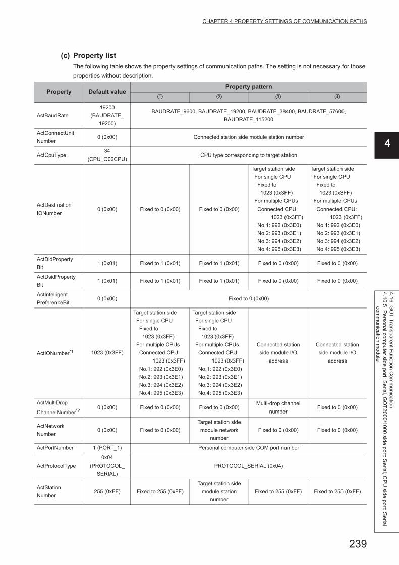
239
CHAPTER 4 PROPERTY SETTINGS OF COMMUNICATION PATHS
4
4.16 GO
T T
ransparent F
unction Com
munication
4.16.5 Pe
rsonal compute
r side port: S
erial, GO
T2000/1000 side port: S
erial, CP
U side port: S
erial com
munica
tion mo
dule
(c) Property list
The following table shows the property settings of communication paths. The setting is not necessary for those
properties without description.
Property Default valueProperty pattern
ActBaudRate
19200
(BAUDRATE_
19200)
BAUDRATE_9600, BAUDRATE_19200, BAUDRATE_38400, BAUDRATE_57600,
BAUDRATE_115200
ActConnectUnit
Number0 (0x00) Connected station side module station number
ActCpuType34
(CPU_Q02CPU)CPU type corresponding to target station
ActDestination
IONumber0 (0x00) Fixed to 0 (0x00) Fixed to 0 (0x00)
Target station side
For single CPU
Fixed to
1023 (0x3FF)
For multiple CPUs
Connected CPU:
1023 (0x3FF)
No.1: 992 (0x3E0)
No.2: 993 (0x3E1)
No.3: 994 (0x3E2)
No.4: 995 (0x3E3)
Target station side
For single CPU
Fixed to
1023 (0x3FF)
For multiple CPUs
Connected CPU:
1023 (0x3FF)
No.1: 992 (0x3E0)
No.2: 993 (0x3E1)
No.3: 994 (0x3E2)
No.4: 995 (0x3E3)
ActDidProperty
Bit1 (0x01) Fixed to 1 (0x01) Fixed to 1 (0x01) Fixed to 0 (0x00) Fixed to 0 (0x00)
ActDsidProperty
Bit1 (0x01) Fixed to 1 (0x01) Fixed to 1 (0x01) Fixed to 0 (0x00) Fixed to 0 (0x00)
ActIntelligent
PreferenceBit0 (0x00) Fixed to 0 (0x00)
ActIONumber*1 1023 (0x3FF)
Target station side
For single CPU
Fixed to
1023 (0x3FF)
For multiple CPUs
Connected CPU:
1023 (0x3FF)
No.1: 992 (0x3E0)
No.2: 993 (0x3E1)
No.3: 994 (0x3E2)
No.4: 995 (0x3E3)
Target station side
For single CPU
Fixed to
1023 (0x3FF)
For multiple CPUs
Connected CPU:
1023 (0x3FF)
No.1: 992 (0x3E0)
No.2: 993 (0x3E1)
No.3: 994 (0x3E2)
No.4: 995 (0x3E3)
Connected station
side module I/O
address
Connected station
side module I/O
address
ActMultiDrop
ChannelNumber*20 (0x00) Fixed to 0 (0x00) Fixed to 0 (0x00)
Multi-drop channel
numberFixed to 0 (0x00)
ActNetwork
Number0 (0x00) Fixed to 0 (0x00)
Target station side
module network
number
Fixed to 0 (0x00) Fixed to 0 (0x00)
ActPortNumber 1 (PORT_1) Personal computer side COM port number
ActProtocolType
0x04
(PROTOCOL_
SERIAL)
PROTOCOL_SERIAL (0x04)
ActStation
Number255 (0xFF) Fixed to 255 (0xFF)
Target station side
module station
number
Fixed to 255 (0xFF) Fixed to 255 (0xFF)
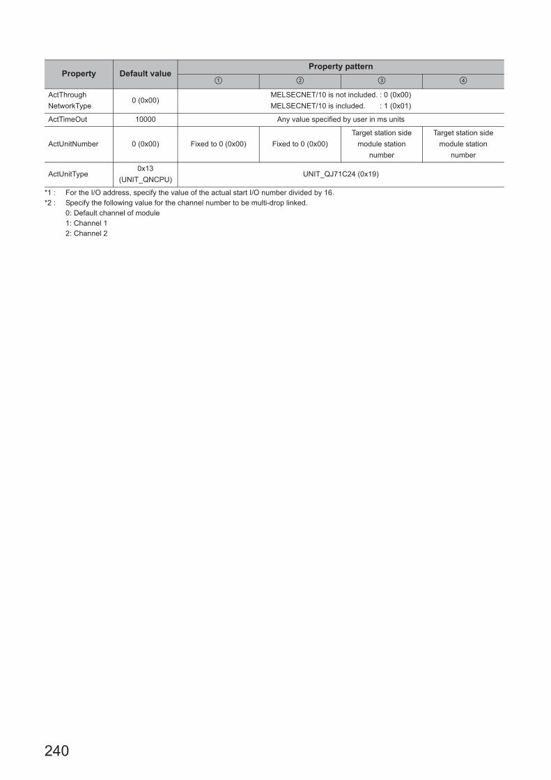
240
*1 : For the I/O address, specify the value of the actual start I/O number divided by 16.*2 : Specify the following value for the channel number to be multi-drop linked.
0: Default channel of module1: Channel 12: Channel 2
ActThrough
NetworkType0 (0x00)
MELSECNET/10 is not included. : 0 (0x00)
MELSECNET/10 is included. : 1 (0x01)
ActTimeOut 10000 Any value specified by user in ms units
ActUnitNumber 0 (0x00) Fixed to 0 (0x00) Fixed to 0 (0x00)
Target station side
module station
number
Target station side
module station
number
ActUnitType0x13
(UNIT_QNCPU)UNIT_QJ71C24 (0x19)
Property Default valueProperty pattern
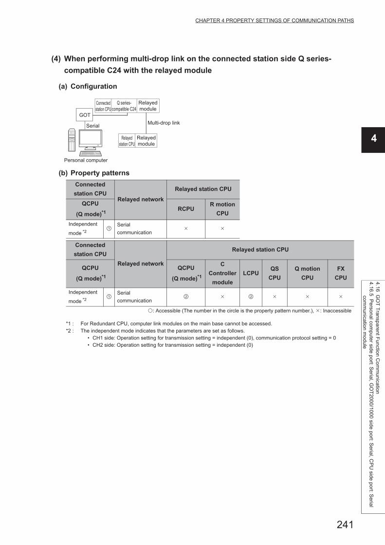
241
CHAPTER 4 PROPERTY SETTINGS OF COMMUNICATION PATHS
4
4.16 GO
T T
ransparent F
unction Com
munication
4.16.5 Pe
rsonal compute
r side port: S
erial, GO
T2000/1000 side port: S
erial, CP
U side port: S
erial com
munica
tion mo
dule
(4) When performing multi-drop link on the connected station side Q series-
compatible C24 with the relayed module
(a) Configuration
(b) Property patterns
*1 : For Redundant CPU, computer link modules on the main base cannot be accessed.*2 : The independent mode indicates that the parameters are set as follows.
• CH1 side: Operation setting for transmission setting = independent (0), communication protocol setting = 0 • CH2 side: Operation setting for transmission setting = independent (0)
Connected
station CPURelayed network
Relayed station CPU
QCPU
(Q mode)*1RCPU
R motion
CPU
Independent
mode *2
Serial
communication
Connected
station CPU
Relayed network
Relayed station CPU
QCPU
(Q mode)*1
QCPU
(Q mode)*1
C
Controller
module
LCPUQS
CPU
Q motion
CPU
FX
CPU
Independent
mode *2
Serial
communication
: Accessible (The number in the circle is the property pattern number.), : Inaccessible
Serial
GOT
Personal computer
Connected
station CPU
Relayed
station CPU
Relayed
module
Q series-
compatible C24
Relayed
module
Multi-drop link

242
(c) Property list
The following table shows the property settings of communication paths. The setting is not necessary for those
properties without description.
*1 : For the I/O address, specify the value of the actual start I/O number divided by 16.*2 : Specify the following value for the channel number to be multi-drop linked.
0: Default channel of module1: Channel 12: Channel 2
Property Default valueProperty pattern
ActBaudRate19200
(BAUDRATE_19200)
Q series BAUDRATE_9600, BAUDRATE_19200,
BAUDRATE_38400, BAUDRATE_57600, BAUDRATE_115200
ActConnectUnitNumber 0 (0x00) Connected station side module station number
ActControl8
(TRC_DTR_OR_RTS)Depending on used cable.
ActCpuType 34 (CPU_Q02CPU) CPU type corresponding to target station
ActDestinationIONumber 0 (0x00) Fixed to 0 (0x00)
Target station side
For single CPU
Fixed to 1023 (0x3FF)
For multiple CPUs
Connected CPU:
1023 (0x3FF)
No.1: 992 (0x3E0)
No.2: 993 (0x3E1)
No.3: 994 (0x3E2)
No.4: 995 (0x3E3)
ActDidPropertyBit 1 (0x01) Fixed to 1 (0x01) Fixed to 0 (0x00)
ActDsidPropertyBit 1 (0x01) Fixed to 1 (0x01) Fixed to 0 (0x00)
ActIntelligentPreferenceBit 0 (0x00) Fixed to 0 (0x00)
ActIONumber*2 1023 (0x3FF)
For single CPU
Fixed to 1023 (0x3FF)
For multiple CPUs
Connected CPU:
1023 (0x3FF)
No.1: 992 (0x3E0)
No.2: 993 (0x3E1)
No.3: 994 (0x3E2)
No.4: 995 (0x3E3)
Connected station side module
I/O address
ActMultiDropChannelNumber*1 0 (0x00) Fixed to 0 (0x00)Multi-drop channel
number
ActNetworkNumber 0 (0x00) Fixed to 0 (0x00)
ActParity 1 (ODD_PARITY) Match to the setting of Q series-compatible C24.
ActPortNumber 1 (PORT_1) Personal computer side COM port number
ActProtocolType0x04
(PROTOCOL_SERIAL)PROTOCOL_SERIAL (0x04)
ActStationNumber 255 (0xFF) Fixed to 255 (0xFF)
ActThroughNetworkType 0 (0x00)MELSECNET/10 is not included. : 0 (0x00)
MELSECNET/10 is included. : 1 (0x01)
ActTimeOut 10000 Any value specified by user in ms units
ActUnitNumber 0 (0x00) Fixed to 0 (0x00)Target station side module
station number
ActUnitType 0x13 (UNIT_QNCPU) UNIT_QJ71C24 (0x19)

243
CHAPTER 4 PROPERTY SETTINGS OF COMMUNICATION PATHS
4
4.16 GO
T T
ransparent F
unction Com
munication
4.16.5 Pe
rsonal compute
r side port: S
erial, GO
T2000/1000 side port: S
erial, CP
U side port: S
erial com
munica
tion mo
dule
(5) When a relayed module other than the connected station side L series-
compatible C24 exists
(a) Configuration
(b) Property patterns
*1 : Redundant CPU cannot be accessed.*2 : Since CC-Link IE Controller Network is not supported, LCPU relayed by CC-Link IE Controller Network cannot be
accessed.*3 : Since CC-Link IE Field Network is not supported, Q12DCCPU-V (Basic mode) relayed by CC-Link IE Field Network
cannot be accessed.
Connected
station CPURelayed network
Relayed station CPU
LCPU RCPUR motion
CPU
CC IE Field*2
MELSECNET/H
Ethernet
Serial
communication
CC-Link
Connected
station CPU
Relayed network
Relayed station CPU
LCPUQCPU
(Q mode)*1
C
Controller
module
LCPUQS
CPU
Q motion
CPU
FX
CPU
CC IE Field*2 *3
MELSECNET/H
Ethernet
Serial
communication
CC-Link
: Accessible (The number in the circle is the property pattern number.), : Inaccessible
Serial
GOT
Personal computer
Connected
station CPU
Relayed
station CPU
Relayed
module
L series-
compatible C24
Relayed
module
Relayed network
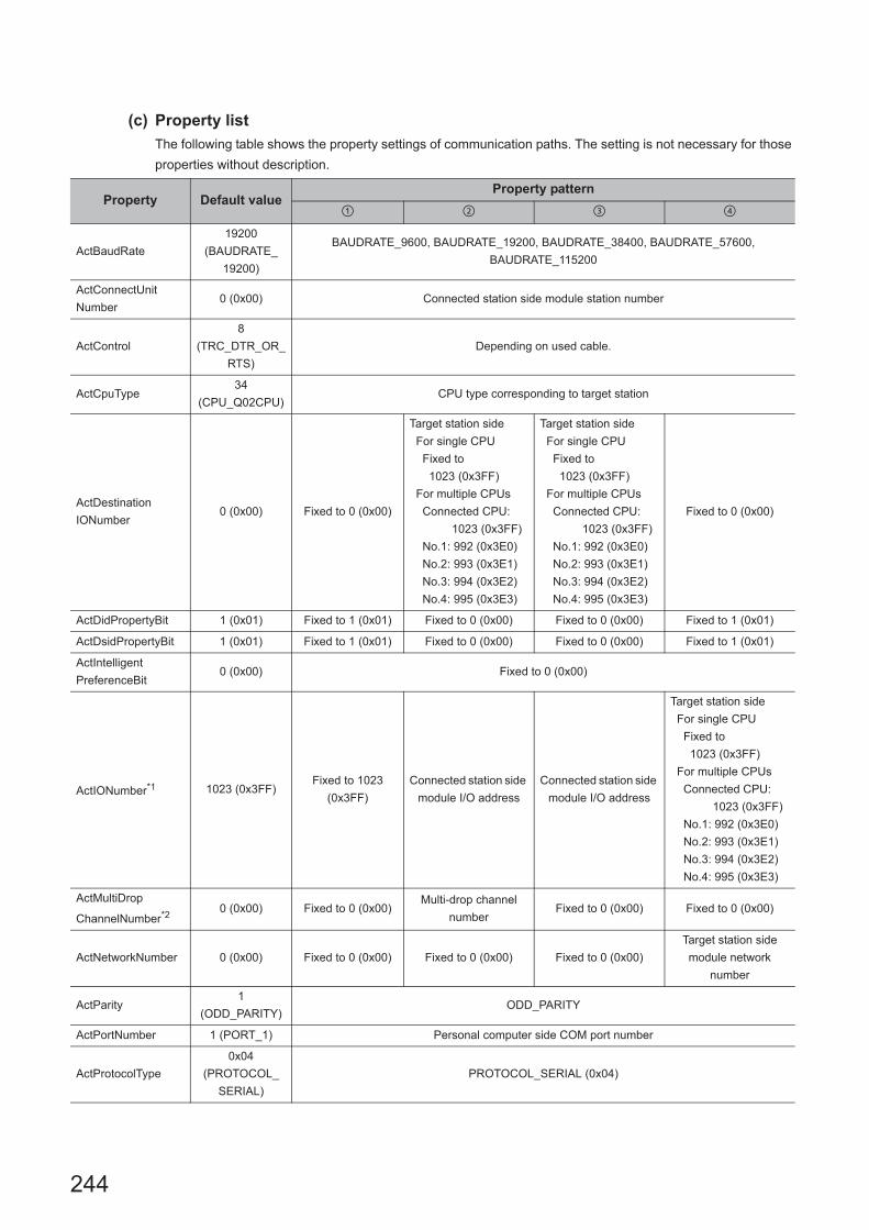
244
(c) Property list
The following table shows the property settings of communication paths. The setting is not necessary for those
properties without description.
Property Default valueProperty pattern
ActBaudRate
19200
(BAUDRATE_
19200)
BAUDRATE_9600, BAUDRATE_19200, BAUDRATE_38400, BAUDRATE_57600,
BAUDRATE_115200
ActConnectUnit
Number0 (0x00) Connected station side module station number
ActControl
8
(TRC_DTR_OR_
RTS)
Depending on used cable.
ActCpuType34
(CPU_Q02CPU)CPU type corresponding to target station
ActDestination
IONumber0 (0x00) Fixed to 0 (0x00)
Target station side
For single CPU
Fixed to
1023 (0x3FF)
For multiple CPUs
Connected CPU:
1023 (0x3FF)
No.1: 992 (0x3E0)
No.2: 993 (0x3E1)
No.3: 994 (0x3E2)
No.4: 995 (0x3E3)
Target station side
For single CPU
Fixed to
1023 (0x3FF)
For multiple CPUs
Connected CPU:
1023 (0x3FF)
No.1: 992 (0x3E0)
No.2: 993 (0x3E1)
No.3: 994 (0x3E2)
No.4: 995 (0x3E3)
Fixed to 0 (0x00)
ActDidPropertyBit 1 (0x01) Fixed to 1 (0x01) Fixed to 0 (0x00) Fixed to 0 (0x00) Fixed to 1 (0x01)
ActDsidPropertyBit 1 (0x01) Fixed to 1 (0x01) Fixed to 0 (0x00) Fixed to 0 (0x00) Fixed to 1 (0x01)
ActIntelligent
PreferenceBit0 (0x00) Fixed to 0 (0x00)
ActIONumber*1 1023 (0x3FF)Fixed to 1023
(0x3FF)
Connected station side
module I/O address
Connected station side
module I/O address
Target station side
For single CPU
Fixed to
1023 (0x3FF)
For multiple CPUs
Connected CPU:
1023 (0x3FF)
No.1: 992 (0x3E0)
No.2: 993 (0x3E1)
No.3: 994 (0x3E2)
No.4: 995 (0x3E3)
ActMultiDrop
ChannelNumber*20 (0x00) Fixed to 0 (0x00)
Multi-drop channel
numberFixed to 0 (0x00) Fixed to 0 (0x00)
ActNetworkNumber 0 (0x00) Fixed to 0 (0x00) Fixed to 0 (0x00) Fixed to 0 (0x00)
Target station side
module network
number
ActParity1
(ODD_PARITY)ODD_PARITY
ActPortNumber 1 (PORT_1) Personal computer side COM port number
ActProtocolType
0x04
(PROTOCOL_
SERIAL)
PROTOCOL_SERIAL (0x04)

245
CHAPTER 4 PROPERTY SETTINGS OF COMMUNICATION PATHS
4
4.16 GO
T T
ransparent F
unction Com
munication
4.16.5 Pe
rsonal compute
r side port: S
erial, GO
T2000/1000 side port: S
erial, CP
U side port: S
erial com
munica
tion mo
dule
*1 : For the I/O address, specify the value of the actual start I/O number divided by 16.*2 : Specify the following value for the channel number to be multi-drop linked.
0: Default channel of module1: Channel 12: Channel 2
ActStationNumber 255 (0xFF)Fixed to 255
(0xFF)Fixed to 255 (0xFF) Fixed to 255 (0xFF)
Target station side
module station number
ActThrough
NetworkType0 (0x00)
MELSECNET/10 is not included. : 0 (0x00)
MELSECNET/10 is included. : 1 (0x01)
ActTimeOut 10000 Any value specified by user in ms units
ActUnitNumber 0 (0x00) Fixed to 0 (0x00)Target station side
module station number
Target station side
module station numberFixed to 0 (0x00)
ActUnitType0x13
(UNIT_QNCPU)UNIT_LJ71C24 (0x54)
Property Default valueProperty pattern

246
(6) When performing multi-drop link on the connected station side L series-
compatible C24 with the relayed module
(a) Configuration
(b) Property patterns
*1 : Redundant CPU cannot be accessed.*2 : The independent mode indicates that the parameters are set as follows.
• CH1 side: Operation setting for transmission setting = independent (0), communication protocol setting = 0 • CH2 side: Operation setting for transmission setting = independent (0)
Connected
station CPURelayed network
Relayed station CPU
LCPU RCPUR motion
CPU
Independent
mode *2
Serial
communication
Connected
station CPU
Relayed network
Relayed station CPU
LCPUQCPU
(Q mode)*1
C
Controller
module
LCPUQS
CPU
Q motion
CPU
FX
CPU
Independent
mode *2
Serial
communication
: Accessible (The number in the circle is the property pattern number.), : Inaccessible
Serial
GOT
Personal computer
Connected
station CPU
Relayed
station CPU
Relayed
module
L series-
compatible C24
Relayed
module
Multi-drop link

247
CHAPTER 4 PROPERTY SETTINGS OF COMMUNICATION PATHS
4
4.16 GO
T T
ransparent F
unction Com
munication
4.16.5 Pe
rsonal compute
r side port: S
erial, GO
T2000/1000 side port: S
erial, CP
U side port: S
erial com
munica
tion mo
dule
(c) Property list
The following table shows the property settings of communication paths. The setting is not necessary for those
properties without description.
*1 : For the I/O address, specify the value of the actual start I/O number divided by 16.*2 : Specify the following value for the channel number to be multi-drop linked.
0: Default channel of module1: Channel 12: Channel 2
Property Default valueProperty pattern
ActBaudRate19200
(BAUDRATE_19200)
BAUDRATE_9600, BAUDRATE_19200,
BAUDRATE_38400, BAUDRATE_57600,
BAUDRATE_115200
ActConnectUnitNumber 0 (0x00) Connected station side module station number
ActControl8
(TRC_DTR_OR_RTS)Depending on used cable.
ActCpuType 34 (CPU_Q02CPU) CPU type corresponding to target station
ActDestinationIONumber 0 (0x00) Fixed to 0 (0x00)
Target station side
For single CPU
Fixed to
1023 (0x3FF)
For multiple CPUs
Connected CPU:
1023 (0x3FF)
No.1: 992 (0x3E0)
No.2: 993 (0x3E1)
No.3: 994 (0x3E2)
No.4: 995 (0x3E3)
ActDidPropertyBit 1 (0x01) Fixed to 1 (0x01) Fixed to 0 (0x00)
ActDsidPropertyBit 1 (0x01) Fixed to 1 (0x01) Fixed to 0 (0x00)
ActIntelligentPreferenceBit 0 (0x00) Fixed to 0 (0x00)
ActIONumber*1 1023 (0x3FF) Fixed to 1023 (0x3FF)Connected station side
module I/O address
ActMultiDropChannelNumber*2 0 (0x00) Fixed to 0 (0x00)Multi-drop channel
number
ActNetworkNumber 0 (0x00) Fixed to 0 (0x00)
ActParity 1 (ODD_PARITY) Match to the setting of L series-compatible C24.
ActPortNumber 1 (PORT_1) Personal computer side COM port number
ActProtocolType0x04
(PROTOCOL_SERIAL)PROTOCOL_SERIAL (0x04)
ActStationNumber 255 (0xFF) Fixed to 255 (0xFF)
ActThroughNetworkType 0 (0x00)MELSECNET/10 is not included. : 0 (0x00)
MELSECNET/10 is included. : 1 (0x01)
ActTimeOut 10000 Any value specified by user in ms units
ActUnitNumber 0 (0x00) Fixed to 0 (0x00)Target station side
module station number
ActUnitType 0x13 (UNIT_QNCPU) UNIT_LJ71C24 (0x54)

248
4.16.6 Personal computer side port: USB, GOT2000/1000 side port: USB, CPU side port: Serial communication module
(1) When a relayed module other than the connected station side R series-
compatible C24 exists
(a) Configuration
(b) Property patterns
*1 : Relayed stations cannot be accessed via R motion CPU.*2 : Since CC-Link IE Controller Network is not supported, RCPU relayed by CC-Link IE Controller Network cannot be accessed.*3 : Only CPU No.2 or later in a multiple CPU configuration can be accessed.
Connected station CPU
Relayed network
Relayed station CPU
RCPUR motion
CPURCPU
R motion
CPU
*1,*3
CC IE Control
CC IE Field*2
MELSECNET/H
Ethernet
Serial
communication
CC-Link
Connected station CPU
Relayed network
Relayed station CPU
RCPUR motion
CPU
QCPU
(Q mode)
C
Controller
module
LCPUQS
CPU
Q motion
CPU
FX
CPU
*1,*3
CC IE Control
CC IE Field
MELSECNET/H
Ethernet
Serial
communication
CC-Link
: Accessible (The number in the circle is the property pattern number.), : Inaccessible
Personal computer
Connected
station CPU
Relayed
module
Relayed network
Relayed
station CPU
Relayed
module
USB
GOT
R series-
compatible C24

249
CHAPTER 4 PROPERTY SETTINGS OF COMMUNICATION PATHS
4
4.16 GO
T T
ransparent F
unction Com
munication
4.16.6 Pe
rsonal compute
r side port: U
SB
, GO
T2000/1
000 side port: U
SB
, CP
U side port: S
erial com
munica
tion mo
dule
(c) Property list
The following table shows the property settings of communication paths. The setting is not necessary for those
properties without description.
Property Default valueProperty pattern
*1
ActConnectUnit
Number0(0x00) Connected station side module station number
ActCpuType34
(CPU_Q02CPU)CPU type corresponding to target station
ActDestination
IONumber *20 (0x00) Fixed to 0 (0x00) Fixed to 0 (0x00)
Target station side
For single CPU
Fixed to
1023 (0x3FF)
For multiple CPUs
Connected CPU:
1023 (0x3FF)
No.1: 992 (0x3E0)
No.2: 993 (0x3E1)
No.3: 994 (0x3E2)
No.4: 995 (0x3E3)
Target station side
For single CPU
Fixed to
1023 (0x3FF)
For multiple CPUs
Connected CPU:
1023 (0x3FF)
No.1: 992 (0x3E0)
No.2: 993 (0x3E1)
No.3: 994 (0x3E2)
No.4: 995 (0x3E3)
ActDidPropertyBit 1 (0x01) Fixed to 1 (0x01) Fixed to 1 (0x01) Fixed to 0 (0x00) Fixed to 0 (0x00)
ActDsidPropertyBit 1 (0x01) Fixed to 1 (0x01) Fixed to 1 (0x01) Fixed to 0 (0x00) Fixed to 0 (0x00)
ActIntelligent
PreferenceBit0 (0x00) Fixed to 0 (0x00) Fixed to 0 (0x00) Fixed to 0 (0x00) Fixed to 0 (0x00)
ActIONumber *2 1023 (0x3FF)
For single CPU
Fixed to
1023 (0x3FF)
For multiple CPUs
Connected CPU:
1023 (0x3FF)
No.1: 992 (0x3E0)
No.2: 993 (0x3E1)
No.3: 994 (0x3E2)
No.4: 995 (0x3E3)
Target station side
For single CPU
Fixed to
1023 (0x3FF)
For multiple CPUs
Connected CPU:
1023 (0x3FF)
No.1: 992 (0x3E0)
No.2: 993 (0x3E1)
No.3: 994 (0x3E2)
No.4: 995 (0x3E3)
Connected station
side module I/O
address
Connected station
side module I/O
address
ActMultiDrop
ChannelNumber *30 (0x00) Fixed to 0 (0x00) Fixed to 0 (0x00)
Multi-drop channel
numberFixed to 0 (0x00)
ActNetworkNumber *4 0 (0x00) Fixed to 0 (0x00)
Target station side
module network
number
Fixed to 0 (0x00) Fixed to 0 (0x00)
ActProtocolType
0x04
(PROTOCOL_
SERIAL)
PROTOCOL_USBGOT
ActPacketType0x01
(PACKET_PLC1)PACKET_PLC1
ActPortNumber 1 (PORT_1) Fixed to 0 (0x00)
ActBaudRate
19200
(BAUDRATE_
19200)
Fixed to 0 (0x00)
ActHostAddress 1.1.1.1 Fixed to NULL
ActCpuTimeOut 0(0x00) Fixed to 0 (0x00)
ActControl8(TRC_DTR_
OR_RTS)Fixed to 0 (0x00)

250
*1 : When accessing via Ethernet module (R series-compatible E71), consider the following: • For ActNetworkNumber and ActStationNumber, specify the value set to R series-compatible E71 parameter settings on the target
station side. • Set "MNET/10 routing information" to R series-compatible E71 parameter setting. When setting parameters,
specify other than Automatic Response System (either of IP address calculation system, table conversion system, or combined system) for "MNET/H routing information".
*2 : For the I/O address, specify the value of the actual start I/O number divided by 16.*3 : Specify the following value for the channel number to be multi-drop linked.
0: Default channel of module1: Channel 12: Channel 2
ActDataBits 8(DATABIT_8) Fixed to 0 (0x00)
ActParity 1(ODD_PARITY) Fixed to 0 (0x00)
ActStopBits0(STOPBIT_
ONE)Fixed to 0 (0x00)
ActSumCheck0(NO_SUM_
CHECK)Fixed to 0 (0x00)
ActSourceNetwork
Number0(0x00) Fixed to 0 (0x00)
ActSourceStation
Number0(0x00) Fixed to 0 (0x00)
ActDestinationPort
Number0(0x00) Fixed to 0 (0x00)
ActStationNumber *4 255 (0xFF) Fixed to 255 (0xFF)
Target station side
module station
number
Fixed to 255 (0xFF) Fixed to 255 (0xFF)
ActThroughNetwork
Type0 (0x00)
MELSECNET/10 is not included. : 0 (0x00)
MELSECNET/10 is included. : 1 (0x01)
ActTimeOut 10000 Any value specified by user in ms units
ActUnitNumber 0 (0x00) Fixed to 0 (0x00) Fixed to 0 (0x00)
Target station side
module station
number
Target station side
module station
number
ActUnitType0x13
(UNIT_QNCPU)UNIT_RJ71C24
Property Default valueProperty pattern
*1

251
CHAPTER 4 PROPERTY SETTINGS OF COMMUNICATION PATHS
4
4.16 GO
T T
ransparent F
unction Com
munication
4.16.6 Pe
rsonal compute
r side port: U
SB
, GO
T2000/1
000 side port: U
SB
, CP
U side port: S
erial com
munica
tion mo
dule
(2) When performing multi-drop link on the connected station side R series-
compatible C24 with the relayed module
(a) Configuration
(b) Property patterns
*1 : Relayed stations cannot be accessed via R motion CPU.*2 : Redundant CPU cannot be accessed.*3 : The independent mode indicates that the parameters are set as follows.
• CH1 side: Operation setting for transmission setting = independent (0), communication protocol setting = 0 • CH2 side: Operation setting for transmission setting = independent (0)
*4 : Only CPU No.2 or later in a multiple CPU configuration can be accessed.
Connected
station CPU
Relayed network
Relayed station CPU
RCPU,
R motion
CPU *1,*4
RCPUR motion
CPU
Independent
mode *3
Serial
communication
Connected
station CPU
Relayed network
Relayed station CPU
RCPU,
R motion
CPU *1,*4
QCPU
(Q mode)*2
C
Controller
module
LCPUQS
CPU
Q motion
CPU
FX
CPU
Independent
mode *3
Serial
communication
: Accessible (The number in the circle is the property pattern number.), : Inaccessible
Personal computer
USB
Connectedstation CPU
Multi-drop link
Relayedstation CPU
Relayedmodule
R series-compatible C24
GOT

252
(c) Property list
The following table shows the property settings of communication paths. The setting is not necessary for those
properties without description.
Property Default valueProperty pattern
ActConnectUnitNumber 0(0x00) Connected station side module station number
ActCpuType34
(CPU_Q02CPU)CPU type corresponding to target station
ActDestinationIONumber *1 0 (0x00) Fixed to 0 (0x00)
Target station side
For single CPU
Fixed to
1023 (0x3FF)
For multiple CPUs
Connected CPU:
1023 (0x3FF)
No.1: 992 (0x3E0)
No.2: 993 (0x3E1)
No.3: 994 (0x3E2)
No.4: 995 (0x3E3)
ActDidPropertyBit 1 (0x01) Fixed to 1 (0x01) Fixed to 0 (0x00)
ActDsidPropertyBit 1 (0x01) Fixed to 1 (0x01) Fixed to 0 (0x00)
ActIntelligentPreferenceBit 0 (0x00) Fixed to 0 (0x00)
ActIONumber *1 1023 (0x3FF)
For single CPU
Fixed to
1023 (0x3FF)
For multiple CPUs
Connected CPU:
1023 (0x3FF)
No.1: 992 (0x3E0)
No.2: 993 (0x3E1)
No.3: 994 (0x3E2)
No.4: 995 (0x3E3)
Connected station
side module I/O
address
ActMultiDropChannelNumber *2 0 (0x00) Fixed to 0 (0x00)Multi-drop channel
number
ActNetworkNumber 0 (0x00) Fixed to 0 (0x00)
ActProtocolType0x04
(PROTOCOL_SERIAL)PROTOCOL_USBGOT
ActPacketType 0x01(PACKET_PLC1) PACKET_PLC1
ActPortNumber 1 (PORT_1) Fixed to 0 (0x00)
ActBaudRate 19200(BAUDRATE_19200) Fixed to 0 (0x00)
ActHostAddress 1.1.1.1 Fixed to NULL
ActCpuTimeOut 0(0x00) Fixed to 0 (0x00)
ActControl 8(TRC_DTR_OR_RTS) Fixed to 0 (0x00)
ActDataBits 8(DATABIT_8) Fixed to 0 (0x00)
ActParity 1(ODD_PARITY) Fixed to 0 (0x00)
ActStopBits 0(STOPBIT_ONE) Fixed to 0 (0x00)
ActSumCheck 0(NO_SUM_CHECK) Fixed to 0 (0x00)
ActSourceNetworkNumber 0(0x00) Fixed to 0 (0x00)
ActSourceStationNumber 0(0x00) Fixed to 0 (0x00)
ActDestinationPortNumber 0(0x00) Fixed to 0 (0x00)
ActStationNumber 255 (0xFF) Fixed to 255 (0xFF)

253
CHAPTER 4 PROPERTY SETTINGS OF COMMUNICATION PATHS
4
4.16 GO
T T
ransparent F
unction Com
munication
4.16.6 Pe
rsonal compute
r side port: U
SB
, GO
T2000/1
000 side port: U
SB
, CP
U side port: S
erial com
munica
tion mo
dule
*1 : For the I/O address, specify the value of the actual start I/O number divided by 16.*2 : Specify the following value for the channel number to be multi-drop linked.
0: Default channel of module1: Channel 12: Channel 2
ActThroughNetworkType 0 (0x00)MELSECNET/10 is not included. : 0 (0x00)
MELSECNET/10 is included. : 1 (0x01)
ActTimeOut 10000 Any value specified by user in ms units
ActUnitNumber 0 (0x00) Fixed to 0 (0x00)
Target station side
module station
number
ActUnitType0x13
(UNIT_QNCPU)UNIT_RJ71C24
Property Default valueProperty pattern
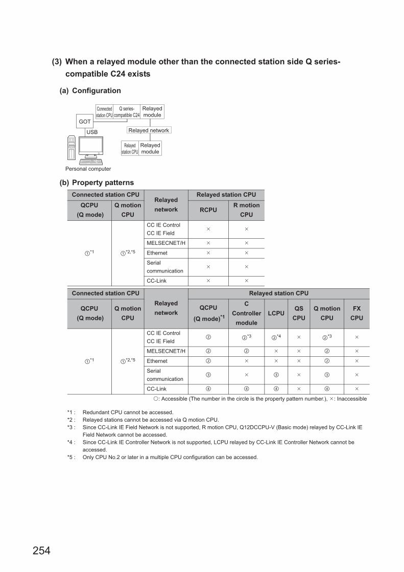
254
(3) When a relayed module other than the connected station side Q series-
compatible C24 exists
(a) Configuration
(b) Property patterns
*1 : Redundant CPU cannot be accessed.*2 : Relayed stations cannot be accessed via Q motion CPU.*3 : Since CC-Link IE Field Network is not supported, R motion CPU, Q12DCCPU-V (Basic mode) relayed by CC-Link IE
Field Network cannot be accessed.*4 : Since CC-Link IE Controller Network is not supported, LCPU relayed by CC-Link IE Controller Network cannot be
accessed.*5 : Only CPU No.2 or later in a multiple CPU configuration can be accessed.
Connected station CPURelayed
network
Relayed station CPU
QCPU
(Q mode)
Q motion
CPURCPU
R motion
CPU
*1 *2,*5
CC IE Control
CC IE Field
MELSECNET/H
Ethernet
Serial
communication
CC-Link
Connected station CPU
Relayed
network
Relayed station CPU
QCPU
(Q mode)
Q motion
CPU
QCPU
(Q mode)*1
C
Controller
module
LCPUQS
CPU
Q motion
CPU
FX
CPU
*1 *2,*5
CC IE Control
CC IE Field *3 *4 *3
MELSECNET/H
Ethernet
Serial
communication
CC-Link
: Accessible (The number in the circle is the property pattern number.), : Inaccessible
Relayed networkUSB
GOT
Personal computer
Connected
station CPU
Relayed
station CPU
Relayed
module
Q series-
compatible C24
Relayed
module

255
CHAPTER 4 PROPERTY SETTINGS OF COMMUNICATION PATHS
4
4.16 GO
T T
ransparent F
unction Com
munication
4.16.6 Pe
rsonal compute
r side port: U
SB
, GO
T2000/1
000 side port: U
SB
, CP
U side port: S
erial com
munica
tion mo
dule
(c) Property list
The following table shows the property settings of communication paths. The setting is not necessary for those
properties without description.
Property Default valueProperty pattern
ActConnectUnit
Number0 (0x00) Connected station side module station number
ActCpuType34
(CPU_Q02CPU)CPU type corresponding to target station
ActDestination
IONumber0 (0x00) Fixed to 0 (0x00) Fixed to 0 (0x00)
Target station side
For single CPU
Fixed to
1023 (0x3FF)
For multiple CPUs
Connected CPU:
1023 (0x3FF)
No.1: 992 (0x3E0)
No.2: 993 (0x3E1)
No.3: 994 (0x3E2)
No.4: 995 (0x3E3)
Target station side
For single CPU
Fixed to
1023 (0x3FF)
For multiple CPUs
Connected CPU:
1023 (0x3FF)
No.1: 992 (0x3E0)
No.2: 993 (0x3E1)
No.3: 994 (0x3E2)
No.4: 995 (0x3E3)
ActDidProperty
Bit1 (0x01) Fixed to 1 (0x01) Fixed to 1 (0x01) Fixed to 0 (0x00) Fixed to 0 (0x00)
ActDsidProperty
Bit1 (0x01) Fixed to 1 (0x01) Fixed to 1 (0x01) Fixed to 0 (0x00) Fixed to 0 (0x00)
ActIntelligent
PreferenceBit0 (0x00) Fixed to 0 (0x00)
ActIONumber*1 1023 (0x3FF)
For single CPU
Fixed to
1023 (0x3FF)
For multiple CPUs
Connected CPU:
1023 (0x3FF)
No.1: 992 (0x3E0)
No.2: 993 (0x3E1)
No.3: 994 (0x3E2)
No.4: 995 (0x3E3)
Target station side
For single CPU
Fixed to
1023 (0x3FF)
For multiple CPUs
Connected CPU:
1023 (0x3FF)
No.1: 992 (0x3E0)
No.2: 993 (0x3E1)
No.3: 994 (0x3E2)
No.4: 995 (0x3E3)
Connected station
side module I/O
address
Connected station
side module I/O
address
ActMultiDrop
ChannelNumber*20 (0x00) Fixed to 0 (0x00) Fixed to 0 (0x00)
Multi-drop channel
numberFixed to 0 (0x00)
ActNetwork
Number0 (0x00) Fixed to 0 (0x00)
Target station side
module network
number
Fixed to 0 (0x00) Fixed to 0 (0x00)
ActProtocolType
0x04
(PROTOCOL_
SERIAL)
PROTOCOL_USBGOT (0x13)
ActStation
Number255 (0xFF) Fixed to 255 (0xFF)
Target station side
module station
number
Fixed to 255 (0xFF) Fixed to 255 (0xFF)
ActThrough
NetworkType0 (0x00)
MELSECNET/10 is not included. : 0 (0x00)
MELSECNET/10 is included. : 1 (0x01)
ActTimeOut 10000 Any value specified by user in ms units

256
*1 : For the I/O address, specify the value of the actual start I/O number divided by 16.*2 : Specify the following value for the channel number to be multi-drop linked.
0: Default channel of module1: Channel 12: Channel 2
ActUnitNumber 0 (0x00) Fixed to 0 (0x00) Fixed to 0 (0x00)
Target station side
module station
number
Target station side
module station
number
ActUnitType0x13
(UNIT_QNCPU)UNIT_QJ71C24 (0x19)
Property Default valueProperty pattern

257
CHAPTER 4 PROPERTY SETTINGS OF COMMUNICATION PATHS
4
4.16 GO
T T
ransparent F
unction Com
munication
4.16.6 Pe
rsonal compute
r side port: U
SB
, GO
T2000/1
000 side port: U
SB
, CP
U side port: S
erial com
munica
tion mo
dule
(4) When performing multi-drop link on the connected station side Q series-
compatible C24 with the relayed module
(a) Configuration
(b) Property patterns
*1 : Redundant CPU cannot be accessed.*2 : The independent mode indicates that the parameters are set as follows.
• CH1 side: Operation setting for transmission setting = independent (0), communication protocol setting = 0 • CH2 side: Operation setting for transmission setting = independent (0)
Connected
station CPURelayed network
Relayed station CPU
QCPU
(Q mode)*1RCPU
R motion
CPU
Independent
mode*2
Serial
communication
Connected
station CPU
Relayed network
Relayed station CPU
QCPU
(Q mode)*1
QCPU
(Q mode)*1
C
Controller
module
LCPUQS
CPU
Q motion
CPU
FX
CPU
Independent
mode*2
Serial
communication
: Accessible (The number in the circle is the property pattern number.), : Inaccessible
Personal computer
USB
Connected
station CPU
Multi-drop link
Relayed
station CPU
Relayed
module
Q series-
compatible C24
GOT

258
(c) Property list
The following table shows the property settings of communication paths. The setting is not necessary for those
properties without description.
*1 : For the I/O address, specify the value of the actual start I/O number divided by 16.*2 : Specify the following value for the channel number to be multi-drop linked.
0: Default channel of module1: Channel 12: Channel 2
Property Default valueProperty pattern
ActConnectUnitNumber 0 (0x00) Connected station side module station number
ActCpuType 34 (CPU_Q02CPU) CPU type corresponding to target station
ActDestinationIONumber 0 (0x00) Fixed to 0 (0x00)
Target station side
For single CPU
Fixed to
1023 (0x3FF)
For multiple CPUs
Connected CPU:
1023 (0x3FF)
No.1: 992 (0x3E0)
No.2: 993 (0x3E1)
No.3: 994 (0x3E2)
No.4: 995 (0x3E3)
ActDidPropertyBit 1 (0x01) Fixed to 1 (0x01) Fixed to 0 (0x00)
ActDsidPropertyBit 1 (0x01) Fixed to 1 (0x01) Fixed to 0 (0x00)
ActIntelligentPreferenceBit 0 (0x00) Fixed to 0 (0x00)
ActIONumber*1 1023 (0x3FF)
For single CPU
Fixed to
1023 (0x3FF)
For multiple CPUs
Connected CPU:
1023 (0x3FF)
No.1: 992 (0x3E0)
No.2: 993 (0x3E1)
No.3: 994 (0x3E2)
No.4: 995 (0x3E3)
Connected station side
module I/O address
ActMultiDropChannelNumber*2 0 (0x00) Fixed to 0 (0x00)Multi-drop channel
number
ActNetworkNumber 0 (0x00) Fixed to 0 (0x00)
ActProtocolType0x04
(PROTOCOL_SERIAL)PROTOCOL_USBGOT (0x13)
ActStationNumber 255 (0xFF) Fixed to 255 (0xFF)
ActThroughNetworkType 0 (0x00)MELSECNET/10 is not included. : 0 (0x00)
MELSECNET/10 is included. : 1 (0x01)
ActTimeOut 10000 Any value specified by user in ms units
ActUnitNumber 0(0x00) Fixed to 0 (0x00)Target station side
module station number
ActUnitType 0x13 (UNIT_QNCPU) UNIT_QJ71C24 (0x19)

259
CHAPTER 4 PROPERTY SETTINGS OF COMMUNICATION PATHS
4
4.16 GO
T T
ransparent F
unction Com
munication
4.16.6 Pe
rsonal compute
r side port: U
SB
, GO
T2000/1
000 side port: U
SB
, CP
U side port: S
erial com
munica
tion mo
dule
(5) When a relayed module other than the connected station side L series-
compatible C24 exists
(a) Configuration
(b) Property patterns
*1 : Redundant CPU cannot be accessed.*2 : Since CC-Link IE Controller Network is not supported, LCPU relayed by CC-Link IE Controller Network cannot be
accessed.*3 : Since CC-Link IE Field Network is not supported, Q12DCCPU-V (Basic mode) relayed by CC-Link IE Field Network
cannot be accessed.
Connected
station CPURelayed network
Relayed station CPU
LCPU RCPUR motion
CPU
CC IE Field*2
MELSECNET/H
Ethernet
Serial
communication
CC-Link
Connected
station CPU
Relayed network
Relayed station CPU
LCPUQCPU
(Q mode)*1
C
Controller
module
LCPUQS
CPU
Q motion
CPU
FX
CPU
CC IE Field*2 *3
MELSECNET/H
Ethernet
Serial
communication
CC-Link
: Accessible (The number in the circle is the property pattern number.), : Inaccessible
USB
GOT
Relayed network
Personal computer
Connected
station CPU
Relayed
station CPU
Relayed
module
L series-
compatible C24
Relayed
module
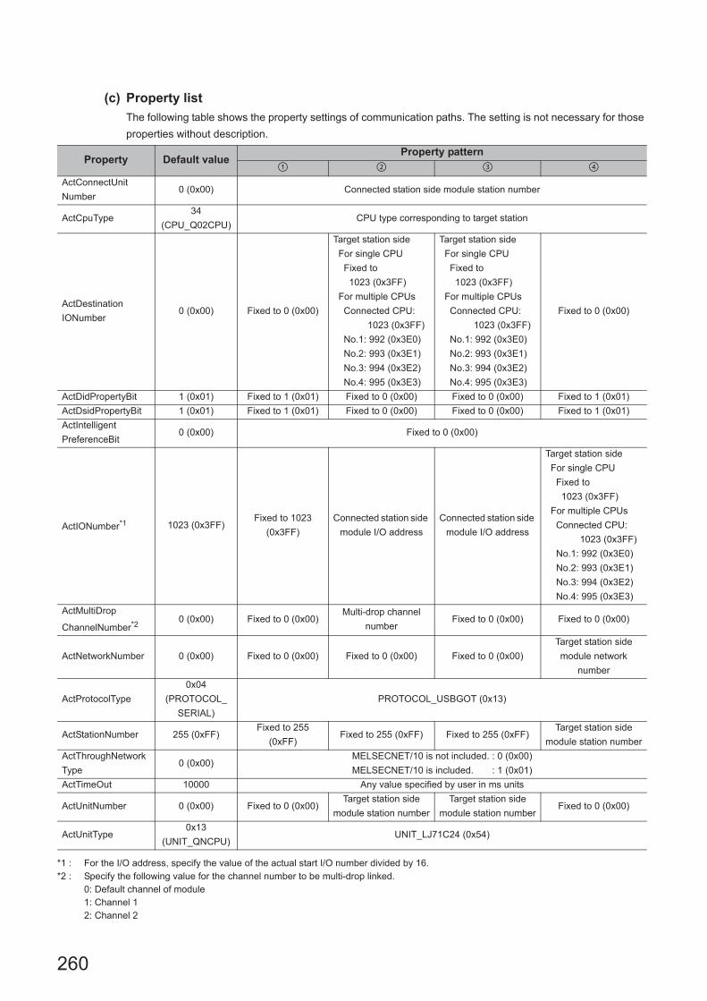
260
(c) Property list
The following table shows the property settings of communication paths. The setting is not necessary for those
properties without description.
*1 : For the I/O address, specify the value of the actual start I/O number divided by 16.*2 : Specify the following value for the channel number to be multi-drop linked.
0: Default channel of module1: Channel 12: Channel 2
Property Default valueProperty pattern
ActConnectUnit
Number0 (0x00) Connected station side module station number
ActCpuType34
(CPU_Q02CPU)CPU type corresponding to target station
ActDestination
IONumber0 (0x00) Fixed to 0 (0x00)
Target station side
For single CPU
Fixed to
1023 (0x3FF)
For multiple CPUs
Connected CPU:
1023 (0x3FF)
No.1: 992 (0x3E0)
No.2: 993 (0x3E1)
No.3: 994 (0x3E2)
No.4: 995 (0x3E3)
Target station side
For single CPU
Fixed to
1023 (0x3FF)
For multiple CPUs
Connected CPU:
1023 (0x3FF)
No.1: 992 (0x3E0)
No.2: 993 (0x3E1)
No.3: 994 (0x3E2)
No.4: 995 (0x3E3)
Fixed to 0 (0x00)
ActDidPropertyBit 1 (0x01) Fixed to 1 (0x01) Fixed to 0 (0x00) Fixed to 0 (0x00) Fixed to 1 (0x01)
ActDsidPropertyBit 1 (0x01) Fixed to 1 (0x01) Fixed to 0 (0x00) Fixed to 0 (0x00) Fixed to 1 (0x01)
ActIntelligent
PreferenceBit0 (0x00) Fixed to 0 (0x00)
ActIONumber*1 1023 (0x3FF)Fixed to 1023
(0x3FF)
Connected station side
module I/O address
Connected station side
module I/O address
Target station side
For single CPU
Fixed to
1023 (0x3FF)
For multiple CPUs
Connected CPU:
1023 (0x3FF)
No.1: 992 (0x3E0)
No.2: 993 (0x3E1)
No.3: 994 (0x3E2)
No.4: 995 (0x3E3)
ActMultiDrop
ChannelNumber*20 (0x00) Fixed to 0 (0x00)
Multi-drop channel
numberFixed to 0 (0x00) Fixed to 0 (0x00)
ActNetworkNumber 0 (0x00) Fixed to 0 (0x00) Fixed to 0 (0x00) Fixed to 0 (0x00)
Target station side
module network
number
ActProtocolType
0x04
(PROTOCOL_
SERIAL)
PROTOCOL_USBGOT (0x13)
ActStationNumber 255 (0xFF)Fixed to 255
(0xFF)Fixed to 255 (0xFF) Fixed to 255 (0xFF)
Target station side
module station number
ActThroughNetwork
Type0 (0x00)
MELSECNET/10 is not included. : 0 (0x00)
MELSECNET/10 is included. : 1 (0x01)
ActTimeOut 10000 Any value specified by user in ms units
ActUnitNumber 0 (0x00) Fixed to 0 (0x00)Target station side
module station number
Target station side
module station numberFixed to 0 (0x00)
ActUnitType0x13
(UNIT_QNCPU)UNIT_LJ71C24 (0x54)
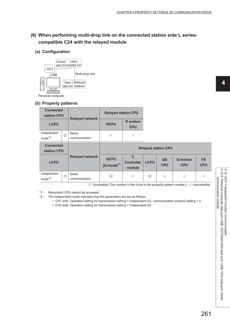
261
CHAPTER 4 PROPERTY SETTINGS OF COMMUNICATION PATHS
4
4.16 GO
T T
ransparent F
unction Com
munication
4.16.6 Pe
rsonal compute
r side port: U
SB
, GO
T2000/1
000 side port: U
SB
, CP
U side port: S
erial com
munica
tion mo
dule
(6) When performing multi-drop link on the connected station side L series-
compatible C24 with the relayed module
(a) Configuration
(b) Property patterns
*1 : Redundant CPU cannot be accessed.*2 : The independent mode indicates that the parameters are set as follows.
• CH1 side: Operation setting for transmission setting = independent (0), communication protocol setting = 0 • CH2 side: Operation setting for transmission setting = independent (0)
Connected
station CPURelayed network
Relayed station CPU
LCPU RCPUR motion
CPU
Independent
mode*2
Serial
communication
Connected
station CPU
Relayed network
Relayed station CPU
LCPUQCPU
(Q mode)*1
C
Controller
module
LCPUQS
CPU
Q motion
CPU
FX
CPU
Independent
mode*2
Serial
communication
: Accessible (The number in the circle is the property pattern number.), : Inaccessible
USB
GOT
Personal computer
Connected
station CPU
Multi-drop link
Relayed
station CPU
Relayed
module
L series-
compatible C24

262
(c) Property list
The following table shows the property settings of communication paths. The setting is not necessary for those
properties without description.
*1 : For the I/O address, specify the value of the actual start I/O number divided by 16.*2 : Specify the following value for the channel number to be multi-drop linked.
0: Default channel of module1: Channel 12: Channel 2
Property Default valueProperty pattern
ActConnectUnitNumber 0 (0x00) Connected station side module station number
ActCpuType 34 (CPU_Q02CPU) CPU type corresponding to target station
ActDestinationIONumber 0 (0x00) Fixed to 0 (0x00)
Target station side
For single CPU
Fixed to
1023 (0x3FF)
For multiple CPUs
Connected CPU:
1023 (0x3FF)
No.1: 992 (0x3E0)
No.2: 993 (0x3E1)
No.3: 994 (0x3E2)
No.4: 995 (0x3E3)
ActDidPropertyBit 1 (0x01) Fixed to 1 (0x01) Fixed to 0 (0x00)
ActDsidPropertyBit 1 (0x01) Fixed to 1 (0x01) Fixed to 0 (0x00)
ActIntelligentPreferenceBit 0 (0x00) Fixed to 0 (0x00)
ActIONumber*1 1023 (0x3FF) Fixed to 1023 (0x3FF)
Connected station side
relayed module I/O
address
ActMultiDropChannelNumber*2 0 (0x00) Fixed to 0 (0x00)Multi-drop channel
number
ActNetworkNumber 0 (0x00) Fixed to 0 (0x00)
ActProtocolType0x04
(PROTOCOL_SERIAL)PROTOCOL_USBGOT (0x13)
ActStationNumber 255 (0xFF) Fixed to 255 (0xFF)
ActThroughNetworkType 0 (0x00)MELSECNET/10 is not included. : 0 (0x00)
MELSECNET/10 is included. : 1 (0x01)
ActTimeOut 10000 Any value specified by user in ms units
ActUnitNumber 0 (0x00) Fixed to 0 (0x00)Target station side
module station number
ActUnitType 0x13 (UNIT_QNCPU) UNIT_LJ71C24 (0x54)

263
CHAPTER 4 PROPERTY SETTINGS OF COMMUNICATION PATHS
4
4.16 GO
T T
ransparent F
unction Com
munication
4.16.7 Personal com
puter sid
e port: Serial, G
OT
2000/1000 side
port: Serial, C
PU
side port: R
series-com
patible E71
4.16.7 Personal computer side port: Serial, GOT2000/1000 side port: Serial, CPU side port: R series-compatible E71
(1) Configuration
(2) Property patterns
*1 : Since CC-Link IE Controller Network is not supported, RCPU relayed by CC-Link IE Controller Network cannot be accessed.
Connected
station CPURelayed network
Relayed station CPU
RCPU RCPUR motion
CPU
CC IE Control
CC IE Field*1
MELSECNET/H
Ethernet
Serial
communication
CC-Link
Connected
station CPU
Relayed network
Relayed station CPU
RCPUQCPU
(Q mode)
C
Controller
module
LCPUQS
CPU
Q motion
CPU
FX
CPU
CC IE Control
CC IE Field
MELSECNET/H
Ethernet
Serial
communication
CC-Link
: Accessible (The number in the circle is the property pattern number.), : Inaccessible
Personal computer
Connected
station CPU
Relayed
module
Relayed network
Relayed
station CPU
Relayed
module
GOT
Serial
R series-
compatible E71Ethernet

264
(3) Property listThe following table shows the property settings of communication paths. The setting is not necessary for those
properties without description.
Property Default valueProperty pattern
ActBaudRate
19200
(BAUDRATE_
19200)
BAUDRATE_9600, BAUDRATE_19200, BAUDRATE_38400,
BAUDRATE_57600, BAUDRATE_115200
ActConnectUnit
Number *10(0x00) Fixed to 0 (0x00)
Connected station
side module station
number
Fixed to 0 (0x00) Fixed to 0 (0x00)
ActCpuType34
(CPU_Q02CPU)CPU type corresponding to target station
ActDestination
IONumber *20 (0x00) Fixed to 0 (0x00) Fixed to 0 (0x00)
Target station side
For single CPU
Fixed to
1023 (0x3FF)
For multiple CPUs
Connected CPU:
1023 (0x3FF)
No.1: 992 (0x3E0)
No.2: 993 (0x3E1)
No.3: 994 (0x3E2)
No.4: 995 (0x3E3)
Target station side
For single CPU
Fixed to
1023 (0x3FF)
For multiple CPUs
Connected CPU:
1023 (0x3FF)
No.1: 992 (0x3E0)
No.2: 993 (0x3E1)
No.3: 994 (0x3E2)
No.4: 995 (0x3E3)
ActDestinationPort
Number0(0x00)
5001 for MELSOFT connection
Any port number for OPS connection. *3
ActDidPropertyBit 1 (0x01) Fixed to 1 (0x01) Fixed to 1 (0x01) Fixed to 0 (0x00) Fixed to 0 (0x00)
ActDsidPropertyBit 1 (0x01) Fixed to 1 (0x01) Fixed to 1 (0x01) Fixed to 0 (0x00) Fixed to 0 (0x00)
ActHostAddress 1.1.1.1 Host name or IP address of connected station side module
ActIONumber *2 1023 (0x3FF)
For single CPU
Fixed to
1023 (0x3FF)
For multiple CPUs
Connected CPU:
1023 (0x3FF)
No.1: 992 (0x3E0)
No.2: 993 (0x3E1)
No.3: 994 (0x3E2)
No.4: 995 (0x3E3)
Target station side
For single CPU
Fixed to
1023 (0x3FF)
For multiple CPUs
Connected CPU:
1023 (0x3FF)
No.1: 992 (0x3E0)
No.2: 993 (0x3E1)
No.3: 994 (0x3E2)
No.4: 995 (0x3E3)
Connected station
side module I/O
address
Connected station
side module I/O
address
ActMultiDrop
ChannelNumber *40 (0x00) Fixed to 0 (0x00) Fixed to 0 (0x00)
Multi-drop channel
numberFixed to 0 (0x00)
ActNetworkNumber *5 0 (0x00)
Target station side
module network
number
Target station side
module network
number
Connected station
side R series-
compatible
E71
network number
Connected station
side R series-
compatible
E71
network number
ActPortNumber 1 (PORT_1) Personal computer side COM port number
ActProtocolType
0x04
(PROTOCOL_
SERIAL)
PROTOCOL_SERIAL

265
CHAPTER 4 PROPERTY SETTINGS OF COMMUNICATION PATHS
4
4.16 GO
T T
ransparent F
unction Com
munication
4.16.7 Personal com
puter sid
e port: Serial, G
OT
2000/1000 side
port: Serial, C
PU
side port: R
series-com
patible E71*1 : When the property pattern is , specify the connected station side R series-compatible E71 station number set to the connected
station side R series-compatible E71 Ethernet parameter.*2 : For the I/O address, specify the value of the actual start I/O number divided by 16.*3 : When using OPS connection function at redundant CPU connection, set the port No. specified to "Host Station Port No." in Network
parameter.*4 : Specify the following value for the channel number to be multi-drop linked.
0: Default channel of module1: Channel 12: Channel 2
*5 : For the property pattern of or , specify the value set in the target station side parameter for ActNetworkNumber and ActStationNumber.
*6 : Specify the same network No. as MELSECNET/10 network No. set to R series-compatible E71 in the Ethernet parameter settings of target station side R series-compatible E71.
*7 : Specify the station number on the GOT side to avoid setting the same station number as set to the R series-compatible E71 on the same Ethernet loop.
ActPacketType0x01
(PACKET_PLC1)PACKET_PLC1
ActCpuTimeOut 0(0x00) Fixed to 0 (0x00)
ActControl8(TRC_DTR_
OR_RTS)Depending on the used cable.
ActDataBits 8(DATABIT_8) Fixed to 8 (0x08)
ActParity 1(ODD_PARITY) Fixed to 1 (0x01)
ActStopBits0(STOPBIT_
ONE)Fixed to 0 (0x00)
ActSumCheck0(NO_SUM_
CHECK)Fixed to 0 (0x00)
ActIntelligent
PreferenceBit0 (0x00) Fixed to 0 (0x00)
ActSourceNetwork
Number *60(0x00) GOT side network number
ActSourceStation
Number *70(0x00) GOT side station number
ActStationNumber *5 255 (0xFF)
Target station side
module station
number
Target station side
module station
number
Connected station
side R series-
compatible
E71
station number
Connected station
side R series-
compatible
E71
station number
ActThroughNetwork
Type0 (0x00)
MELSECNET/10 is not included. : 0 (0x00)
MELSECNET/10 is included. : 1 (0x01)
ActTimeOut 10000 Any value specified by user in ms units
ActUnitNumber 0 (0x00) Fixed to 0 (0x00) Fixed to 0 (0x00)
Target station side
module station
number
Target station side
module station
number
ActUnitType0x13
(UNIT_QNCPU)UNIT_GOT_RJ71EN71
Property Default valueProperty pattern

266
4.16.8 Personal computer side port: Serial, GOT2000/1000 side port: Serial, CPU side port: Q series-compatible E71
(1) Configuration
*1 : The communication cannot be established when a remote password is set to the connected station side Q series-compatible E71.
(2) Property patterns
*1 : Redundant CPU cannot be accessed.*2 : Since CC-Link IE Field Network is not supported, Q12DCCPU-V (Basic mode) relayed by CC-Link IE Field Network
cannot be accessed.*3 : Since CC-Link IE Controller Network is not supported, LCPU relayed by CC-Link IE Controller Network cannot be
accessed.
Connected
station CPURelayed network
Relayed station CPU
QCPU
(Q mode)RCPU
R motion
CPU
*1
CC IE Control
CC IE Field
MELSECNET/H
Ethernet
Serial
communication
CC-Link
Connected
station CPU
Relayed network
Relayed station CPU
QCPU
(Q mode)
QCPU
(Q mode)*1
C
Controller
module
LCPUQS
CPU
Q motion
CPU
FX
CPU
*1
CC IE Control
CC IE Field *2 *3
MELSECNET/H
Ethernet
Serial
communication
CC-Link
: Accessible (The number in the circle is the property pattern number.), : Inaccessible
GOT
Serial
Ethernet
Relayed network
Personal computer
Connected
station CPU
Relayed
station CPU
Relayed
module
Q series-
compatible E71*1
Relayed
module

267
CHAPTER 4 PROPERTY SETTINGS OF COMMUNICATION PATHS
4
4.16 GO
T T
ransparent F
unction Com
munication
4.16.8 Personal com
puter side port: S
erial, GO
T2
000/1000 side p
ort: Serial, C
PU
side port: Q series-
compatible E
71
(3) Property listThe following table shows the property settings of communication paths. The setting is not necessary for those
properties without description.
Property Default valueProperty pattern
ActBaudRate
19200
(BAUDRATE_
19200)
BAUDRATE_9600, BAUDRATE_19200, BAUDRATE_38400, BAUDRATE_57600,
BAUDRATE_115200
ActConnectUnit
Number0 (0x00) Fixed to 0 (0x00)
Connected station
side module station
number
Fixed to 0 (0x00) Fixed to 0 (0x00)
ActCpuType34
(CPU_Q02CPU)CPU type corresponding to target station
ActDestination
IONumber0 (0x00) Fixed to 0 (0x00) Fixed to 0 (0x00)
Target station side
For single CPU
Fixed to
1023 (0x3FF)
For multiple CPUs
Connected CPU:
1023 (0x3FF)
No.1: 992 (0x3E0)
No.2: 993 (0x3E1)
No.3: 994 (0x3E2)
No.4: 995 (0x3E3)
Target station side
For single CPU
Fixed to
1023 (0x3FF)
For multiple CPUs
Connected CPU:
1023 (0x3FF)
No.1: 992 (0x3E0)
No.2: 993 (0x3E1)
No.3: 994 (0x3E2)
No.4: 995 (0x3E3)
ActDestination
PortNumber0 (0x00) 5001
ActDidProperty
Bit1 (0x01) Fixed to 1 (0x01) Fixed to 1 (0x01) Fixed to 0 (0x00) Fixed to 0 (0x00)
ActDsidProperty
Bit1 (0x01) Fixed to 1 (0x01) Fixed to 1 (0x01) Fixed to 0 (0x00) Fixed to 0 (0x00)
ActHostAddress 1.1.1.1 Host name or IP address of connected station side module
ActIONumber*1 1023 (0x3FF)
For single CPU
Fixed to
1023 (0x3FF)
For multiple CPUs
Connected CPU:
1023 (0x3FF)
No.1: 992 (0x3E0)
No.2: 993 (0x3E1)
No.3: 994 (0x3E2)
No.4: 995 (0x3E3)
Target station side
For single CPU
Fixed to
1023 (0x3FF)
For multiple CPUs
Connected CPU:
1023 (0x3FF)
No.1: 992 (0x3E0)
No.2: 993 (0x3E1)
No.3: 994 (0x3E2)
No.4: 995 (0x3E3)
Connected station
side relayed module
I/O address
Connected station
side relayed module
I/O address
ActMultiDrop
ChannelNumber*20 (0x00) Fixed to 0 (0x00) Fixed to 0 (0x00)
Multi-drop channel
numberFixed to 0 (0x00)
ActNetwork
Number*30 (0x00)
Target station side
module network
number
Target station side
module network
number
Connected station
side Q series-
compatible E71
network number
Connected station
side Q series-
compatible E71
network number
ActPortNumber 1 (PORT_1) Personal computer side COM port number
ActProtocolType
0x04
(PROTOCOL_S
ERIAL)
PROTOCOL_SERIAL (0x04)

268
*1 : For the I/O address, specify the value of the actual start I/O number divided by 16.*2 : Specify the following value for the channel number to be multi-drop linked.
0: Default channel of module1: Channel 12: Channel 2
*3 : For the property pattern of or , specify the value set in the target station side parameter for ActNetworkNumber and ActStationNumber.
*4 : Specify the station number on the GOT side to avoid setting the same station number as set to the Q series-compatible E71 on the same Ethernet loop.
ActSource
NetworkNumber0 (0x00) GOT side network number
ActSource
StationNumber*40 (0x00) GOT side station number
ActStation
Number*3255 (0xFF)
Target station side
module station
number
Target station side
module station
number
Connected station
side Q series-
compatible E71
station number
Connected station
side Q series-
compatible E71
station number
ActThrough
NetworkType0 (0x00)
MELSECNET/10 is not included. : 0 (0x00)
MELSECNET/10 is included. : 1 (0x01)
ActTimeOut 10000 Any value specified by user in ms units
ActUnitNumber 0 (0x00) Fixed to 0 (0x00) Fixed to 0 (0x00)
Target station side
module station
number
Target station side
module station
number
ActUnitType0x13
(UNIT_QNCPU)UNIT_GOT_QJ71E71 (0x40)
Property Default valueProperty pattern

269
CHAPTER 4 PROPERTY SETTINGS OF COMMUNICATION PATHS
4
4.16 GO
T T
ransparent F
unction Com
munication
4.16.9 Pe
rsonal compute
r side port: U
SB
, GO
T2000/1
000 side port: U
SB
, CP
U side port: R
series-com
patible E71
4.16.9 Personal computer side port: USB, GOT2000/1000 side port: USB, CPU side port: R series-compatible E71
(1) Configuration
(2) Property patterns
*1 : Since CC-Link IE Controller Network is not supported, RCPU relayed by CC-Link IE Controller Network cannot be accessed.
Connected
station CPURelayed network
Relayed station CPU
RCPU RCPUR motion
CPU
CC IE Control
CC IE Field*1
MELSECNET/H
Ethernet
Serial
communication
CC-Link
Connected
station CPU
Relayed network
Relayed station CPU
RCPUQCPU
(Q mode)
C
Controller
module
LCPUQS
CPU
Q motion
CPU
FX
CPU
CC IE Control
CC IE Field
MELSECNET/H
Ethernet
Serial
communication
CC-Link
: Accessible (The number in the circle is the property pattern number.), : Inaccessible
Personal computer
Connected
station CPU
Relayed
module
Relayed network
Relayed
station CPU
Relayed
module
GOT
R series-
compatible E71Ethernet
USB

270
(3) Property listThe following table shows the property settings of communication paths. The setting is not necessary for those
properties without description.
Property Default valueProperty pattern
ActConnectUnit
Number *10(0x00) Fixed to 0 (0x00)
Connected station
side module station
number
Fixed to 0 (0x00) Fixed to 0 (0x00)
ActCpuType34
(CPU_Q02CPU)CPU type corresponding to target station
ActDestination
IONumber *20 (0x00) Fixed to 0 (0x00) Fixed to 0 (0x00)
Target station side
For single CPU
Fixed to
1023 (0x3FF)
For multiple CPUs
Connected CPU:
1023 (0x3FF)
No.1: 992 (0x3E0)
No.2: 993 (0x3E1)
No.3: 994 (0x3E2)
No.4: 995 (0x3E3)
Target station side
For single CPU
Fixed to
1023 (0x3FF)
For multiple CPUs
Connected CPU:
1023 (0x3FF)
No.1: 992 (0x3E0)
No.2: 993 (0x3E1)
No.3: 994 (0x3E2)
No.4: 995 (0x3E3)
ActDestinationPort
Number0(0x00)
5001 for MELSOFT connection
Any port number for OPS connection. *3
ActDidPropertyBit 1 (0x01) Fixed to 1 (0x01) Fixed to 1 (0x01) Fixed to 0 (0x00) Fixed to 0 (0x00)
ActDsidPropertyBit 1 (0x01) Fixed to 1 (0x01) Fixed to 1 (0x01) Fixed to 0 (0x00) Fixed to 0 (0x00)
ActHostAddress 1.1.1.1 Host name or IP address of connected station side module
ActIONumber *2 1023 (0x3FF)
For single CPU
Fixed to
1023 (0x3FF)
For multiple CPUs
Connected CPU:
1023 (0x3FF)
No.1: 992 (0x3E0)
No.2: 993 (0x3E1)
No.3: 994 (0x3E2)
No.4: 995 (0x3E3)
Target station side
For single CPU
Fixed to
1023 (0x3FF)
For multiple CPUs
Connected CPU:
1023 (0x3FF)
No.1: 992 (0x3E0)
No.2: 993 (0x3E1)
No.3: 994 (0x3E2)
No.4: 995 (0x3E3)
Connected station
side module I/O
address
Connected station
side module I/O
address
ActMultiDrop
ChannelNumber *40 (0x00) Fixed to 0 (0x00) Fixed to 0 (0x00)
Multi-drop channel
numberFixed to 0 (0x00)
ActNetworkNumber *5 0 (0x00)
Target station side
module network
number
Target station side
module network
number
Connected station
side R series-
compatible
E71
network number
Connected station
side R series-
compatible
E71
network number
ActProtocolType
0x04
(PROTOCOL_
SERIAL)
PROTOCOL_USBGOT
ActPacketType0x01
(PACKET_PLC1)PACKET_PLC1
ActPortNumber 1 (PORT_1) Fixed to 0 (0x00)

271
CHAPTER 4 PROPERTY SETTINGS OF COMMUNICATION PATHS
4
4.16 GO
T T
ransparent F
unction Com
munication
4.16.9 Pe
rsonal compute
r side port: U
SB
, GO
T2000/1
000 side port: U
SB
, CP
U side port: R
series-com
patible E71
*1 : When the property pattern is , specify the connected station side R series-compatible E71 station number set to the connected station side R series-compatible E71 Ethernet parameter.
*2 : For the I/O address, specify the value of the actual start I/O number divided by 16.*3 : When using OPS connection function at redundant CPU connection, set the port No. specified to "Host Station Port No." in Network
parameter.*4 : Specify the following value for the channel number to be multi-drop linked.
0: Default channel of module1: Channel 12: Channel 2
*5 : For the property pattern of or , specify the value set in the target station side parameter for ActNetworkNumber and ActStationNumber.
*6 : Specify the same network No. as MELSECNET/10 network No. set to R series-compatible E71 in the Ethernet parameter settings of target station side R series-compatible E71.
*7 : Specify the station number on the GOT side to avoid setting the same station number as set to the R series-compatible E71 on the same Ethernet loop.
ActBaudRate
19200
(BAUDRATE_
19200)
Fixed to 0 (0x00)
ActCpuTimeOut 0(0x00) Fixed to 0 (0x00)
ActControl8(TRC_DTR_
OR_RTS)Fixed to 0 (0x00)
ActDataBits 8(DATABIT_8) Fixed to 0 (0x00)
ActParity 1(ODD_PARITY) Fixed to 0 (0x00)
ActStopBits0(STOPBIT_
ONE)Fixed to 0 (0x00)
ActSumCheck0(NO_SUM_
CHECK)Fixed to 0 (0x00)
ActIntelligent
PreferenceBit0 (0x00) Fixed to 0 (0x00)
ActSourceNetwork
Number *60(0x00) GOT side network number
ActSourceStation
Number *70(0x00) GOT side station number
ActStationNumber *5 255 (0xFF)
Target station side
module station
number
Target station side
module station
number
Connected station
side R series-
compatible
E71
network number
Connected station
side R series-
compatible
E71
network number
ActThroughNetwork
Type0 (0x00)
MELSECNET/10 is not included. : 0 (0x00)
MELSECNET/10 is included. : 1 (0x01)
ActTimeOut 10000 Any value specified by user in ms units
ActUnitNumber 0 (0x00) Fixed to 0 (0x00) Fixed to 0 (0x00)
Target station side
module station
number
Target station side
module station
number
ActUnitType0x13
(UNIT_QNCPU)UNIT_GOT_RJ71EN71
Property Default valueProperty pattern
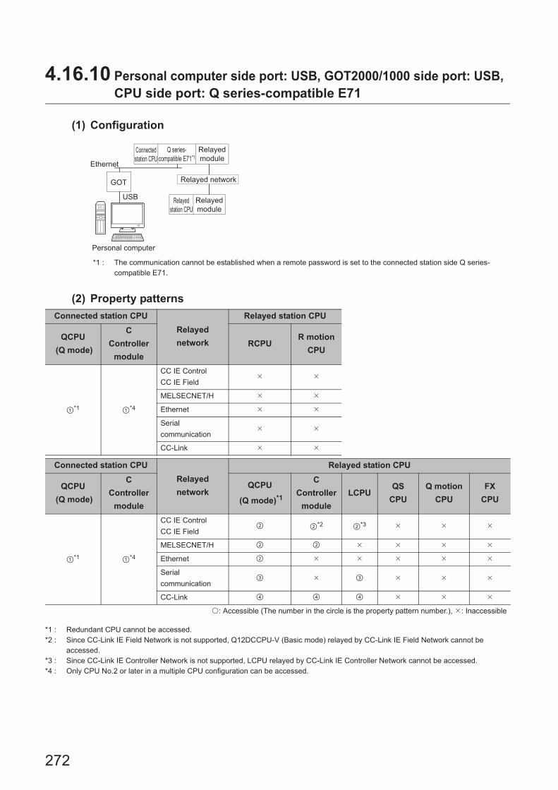
272
4.16.10 Personal computer side port: USB, GOT2000/1000 side port: USB, CPU side port: Q series-compatible E71
(1) Configuration
*1 : The communication cannot be established when a remote password is set to the connected station side Q series-compatible E71.
(2) Property patterns
*1 : Redundant CPU cannot be accessed.*2 : Since CC-Link IE Field Network is not supported, Q12DCCPU-V (Basic mode) relayed by CC-Link IE Field Network cannot be
accessed.*3 : Since CC-Link IE Controller Network is not supported, LCPU relayed by CC-Link IE Controller Network cannot be accessed.*4 : Only CPU No.2 or later in a multiple CPU configuration can be accessed.
Connected station CPU
Relayed
network
Relayed station CPU
QCPU
(Q mode)
C
Controller
module
RCPUR motion
CPU
*1 *4
CC IE Control
CC IE Field
MELSECNET/H
Ethernet
Serial
communication
CC-Link
Connected station CPU
Relayed
network
Relayed station CPU
QCPU
(Q mode)
C
Controller
module
QCPU
(Q mode)*1
C
Controller
module
LCPUQS
CPU
Q motion
CPU
FX
CPU
*1 *4
CC IE Control
CC IE Field *2 *3
MELSECNET/H
Ethernet
Serial
communication
CC-Link
: Accessible (The number in the circle is the property pattern number.), : Inaccessible
GOT
Ethernet
USB
Relayed network
Personal computer
Connected
station CPU
Relayed
station CPU
Relayed
module
Q series-
compatible E71*1
Relayed
module

273
CHAPTER 4 PROPERTY SETTINGS OF COMMUNICATION PATHS
4
4.16 GO
T T
ransparent F
unction Com
munication
4.16.10 P
ersonal computer side port: U
SB
, GO
T2000/1000 side p
ort: US
B, C
PU
side port: Q series-
compatible E
71
(3) Property listThe following table shows the property settings of communication paths. The setting is not necessary for those
properties without description.
Property Default valueProperty pattern
ActConnectUnit
Number0 (0x00) Fixed to 0 (0x00)
Connected station
side module station
number
Fixed to 0 (0x00) Fixed to 0 (0x00)
ActCpuType34
(CPU_Q02CPU)CPU type corresponding to target station
ActDestination
IONumber0 (0x00) Fixed to 0 (0x00) Fixed to 0 (0x00)
Target station side
For single CPU
Fixed to
1023 (0x3FF)
For multiple CPUs
Connected CPU:
1023 (0x3FF)
No.1: 992 (0x3E0)
No.2: 993 (0x3E1)
No.3: 994 (0x3E2)
No.4: 995 (0x3E3)
Target station side
For single CPU
Fixed to
1023 (0x3FF)
For multiple CPUs
Connected CPU:
1023 (0x3FF)
No.1: 992 (0x3E0)
No.2: 993 (0x3E1)
No.3: 994 (0x3E2)
No.4: 995 (0x3E3)
ActDestination
PortNumber0 (0x00) 5001
ActDidProperty
Bit1 (0x01) Fixed to 1 (0x01) Fixed to 1 (0x01) Fixed to 0 (0x00) Fixed to 0 (0x00)
ActDsidProperty
Bit1 (0x01) Fixed to 1 (0x01) Fixed to 1 (0x01) Fixed to 0 (0x00) Fixed to 0 (0x00)
ActHostAddress 1.1.1.1 Host name or IP address of connected station side module
ActIONumber*1 1023 (0x3FF)
Target station side
For single CPU
Fixed to
1023 (0x3FF)
For multiple CPUs
Connected CPU:
1023 (0x3FF)
No.1: 992 (0x3E0)
No.2: 993 (0x3E1)
No.3: 994 (0x3E2)
No.4: 995 (0x3E3)
Target station side
For single CPU
Fixed to
1023 (0x3FF)
For multiple CPUs
Connected CPU:
1023 (0x3FF)
No.1: 992 (0x3E0)
No.2: 993 (0x3E1)
No.3: 994 (0x3E2)
No.4: 995 (0x3E3)
Connected station
side relayed module
I/O address
Connected station
side relayed module
I/O address
ActMultiDrop
ChannelNumber*20 (0x00) Fixed to 0 (0x00) Fixed to 0 (0x00)
Multi-drop channel
numberFixed to 0 (0x00)
ActNetwork
Number*30 (0x00)
Target station side
module network
number
Target station side
module network
number
Connected station
side Q series-
compatible E71
network number
Connected station
side Q series-
compatible E71
network number
ActProtocolType
0x04
(PROTOCOL_
SERIAL)
PROTOCOL_USBGOT (0x13)
ActSource
NetworkNumber0 (0x00) GOT side network number
ActSource
StationNumber*40 (0x00) GOT side station number

274
*1 : For the I/O address, specify the value of the actual start I/O number divided by 16.*2 : Specify the following value for the channel number to be multi-drop linked.
0: Default channel of module1: Channel 12: Channel 2
*3 : For the property pattern of or , specify the value set in the target station side parameter for ActNetworkNumber and ActStationNumber.
*4 : Specify the station number on the GOT side to avoid setting the same station number as set to the Q series-compatible E71 on the same Ethernet loop.
ActStation
Number*3255 (0xFF)
Target station side
module station
number
Target station side
module station
number
Connected station
side Q series-
compatible E71 station
number
Connected station
side Q series-
compatible E71 station
number
ActThrough
NetworkType0 (0x00)
MELSECNET/10 is not included. : 0 (0x00)
MELSECNET/10 is included. : 1 (0x01)
ActTimeOut 10000 Any value specified by user in ms units
ActUnitNumber 0 (0x00) Fixed to 0 (0x00) Fixed to 0 (0x00)
Target station side
module station
number
Target station side
module station
number
ActUnitType0x13
(UNIT_QNCPU)UNIT_GOT_QJ71E71 (0x40)
Property Default valueProperty pattern

275
CHAPTER 4 PROPERTY SETTINGS OF COMMUNICATION PATHS
4
4.16 GO
T T
ransparent F
unction Com
munication
4.16.11 P
ersonal com
puter side port: Serial, G
OT
2000/1000 side port: S
erial, C
PU
side port: Ethernet
port
4.16.11 Personal computer side port: Serial, GOT2000/1000 side port: Serial, CPU side port: Ethernet port
(1) When the connected station is RCPU
(a) Configuration
(b) Property patterns
*1 : Relayed stations cannot be accessed via R motion CPU.*2 : Since CC-Link IE Controller Network is not supported, RCPU relayed by CC-Link IE Controller Network cannot be accessed.*3 : Only CPU No.2 or later in a multiple CPU configuration can be accessed.
Connected station CPURelayed
network
Relayed station CPU
RCPUR motion
CPURCPU
R motion
CPU
*1,*3
CC IE Control
CC IE Field*2
MELSECNET/H
Ethernet
Serial
communication
CC-Link
Connected station CPU
Relayed
network
Relayed station CPU
RCPUR motion
CPU
QCPU
(Q mode)
C
Controller
module
LCPUQS
CPU
Q motion
CPU
FX
CPU
*1,*3
CC IE Control
CC IE Field
MELSECNET/H
Ethernet
Serial
communication
CC-Link
: Accessible (The number in the circle is the property pattern number.), : Inaccessible
Personal computer
Connected
station CPU
Relayed
module
Relayed network
Relayed
station CPU
Relayed
module
GOT
Serial
Ethernet

276
(c) Property list
The following table shows the property settings of communication paths. The setting is not necessary for those
properties without description.
Property Default valueProperty pattern
*1
ActBaudRate
19200
(BAUDRATE_
19200)
BAUDRATE_9600, BAUDRATE_19200, BAUDRATE_38400,
BAUDRATE_57600, BAUDRATE_115200
ActCpuType34
(CPU_Q02CPU)CPU type corresponding to target station
ActDestination
IONumber *20 (0x00) Fixed to 0 (0x00) Fixed to 0 (0x00)
Target station side
For single CPU
Fixed to
1023 (0x3FF)
For multiple CPUs
Connected CPU:
1023 (0x3FF)
No.1: 992 (0x3E0)
No.2: 993 (0x3E1)
No.3: 994 (0x3E2)
No.4: 995 (0x3E3)
Target station side
For single CPU
Fixed to
1023 (0x3FF)
For multiple CPUs
Connected CPU:
1023 (0x3FF)
No.1: 992 (0x3E0)
No.2: 993 (0x3E1)
No.3: 994 (0x3E2)
No.4: 995 (0x3E3)
ActDidPropertyBit 1 (0x01) Fixed to 1 (0x01) Fixed to 1 (0x01) Fixed to 0 (0x00) Fixed to 0 (0x00)
ActDsidPropertyBit 1 (0x01) Fixed to 1 (0x01) Fixed to 1 (0x01) Fixed to 0 (0x00) Fixed to 0 (0x00)
ActHostAddress 1.1.1.1 Host name or IP address of connected station side module
ActIntelligent
PreferenceBit0 (0x00) Fixed to 0 (0x00) Fixed to 0 (0x00)
Target station
RCPU,
QCPU (Q mode),
C Controller module,
LCPU : 1 (0x01)
Other than the
above : 0 (0x00)
Target station
RCPU,
QCPU (Q mode),
C Controller module,
LCPU : 1 (0x01)
Other than the
above : 0 (0x00)
ActIONumber *2 1023 (0x3FF)
For single CPU
Fixed to
1023 (0x3FF)
For multiple CPUs
Connected CPU:
1023 (0x3FF)
No.1: 992 (0x3E0)
No.2: 993 (0x3E1)
No.3: 994 (0x3E2)
No.4: 995 (0x3E3)
Target station side
For single CPU
Fixed to
1023 (0x3FF)
For multiple CPUs
Connected CPU:
1023 (0x3FF)
No.1: 992 (0x3E0)
No.2: 993 (0x3E1)
No.3: 994 (0x3E2)
No.4: 995 (0x3E3)
Connected station
side module I/O
address
Connected station
side module I/O
address
ActMultiDrop
ChannelNumber *30 (0x00) Fixed to 0 (0x00) Fixed to 0 (0x00)
Multi-drop channel
numberFixed to 0 (0x00)
ActNetworkNumber *4 0 (0x00) Fixed to 0 (0x00)
Target station side
module network
number
Fixed to 0 (0x00) Fixed to 0 (0x00)
ActPortNumber 1 (PORT_1) Personal computer side COM port number
ActProtocolType
0x04
(PROTOCOL_
SERIAL)
PROTOCOL_SERIAL
ActPacketType0x01
(PACKET_PLC1)PACKET_PLC1

277
CHAPTER 4 PROPERTY SETTINGS OF COMMUNICATION PATHS
4
4.16 GO
T T
ransparent F
unction Com
munication
4.16.11 P
ersonal com
puter side port: Serial, G
OT
2000/1000 side port: S
erial, C
PU
side port: Ethernet
port
*1 : When accessing via Ethernet module (R series-compatible E71), consider the following: • For ActNetworkNumber and ActStationNumber, specify the value set to R series-compatible E71 parameter settings on the target
station side. • Set "MNET/10 routing information" to R series-compatible E71 parameter setting. When setting parameters,
specify other than Automatic Response System (either of IP address calculation system, table conversion system, or combined system) for "MNET/H routing information".
*2 : For the I/O address, specify the value of the actual start I/O number divided by 16.*3 : Specify the following value for the channel number to be multi-drop linked.
0: Default channel of module1: Channel 12: Channel 2
*4 : For the property pattern of , specify the value set in the target station side parameter for ActNetworkNumber and ActStationNumber.
ActConnectUnit
Number0(0x00) Fixed to 0 (0x00)
ActCpuTimeOut 0(0x00) Fixed to 0 (0x00)
ActControl8(TRC_DTR_
OR_RTS)Depending on the used cable.
ActDataBits 8(DATABIT_8) Fixed to 8 (0x08)
ActParity 1(ODD_PARITY) Fixed to 1 (0x01)
ActStopBits0(STOPBIT_
ONE)Fixed to 0 (0x00)
ActSumCheck0(NO_SUM_
CHECK)Fixed to 0 (0x00)
ActSourceNetwork
Number0(0x00) Fixed to 0 (0x00)
ActSourceStation
Number0(0x00) Fixed to 0 (0x00)
ActDestinationPort
Number0(0x00) 5006
ActStationNumber *4 255 (0xFF) Fixed to 255 (0xFF)
Target station side
module station
number
Fixed to 255 (0xFF) Fixed to 255 (0xFF)
ActThroughNetwork
Type0 (0x00)
MELSECNET/10 is not included. : 0 (0x00)
MELSECNET/10 is included. : 1 (0x01)
ActTimeOut 10000 Any value specified by user in ms units
ActUnitNumber 0 (0x00) Fixed to 0 (0x00) Fixed to 0 (0x00)
Target station side
module station
number
Target station side
module station
number
ActUnitType0x13
(UNIT_QNCPU)UNIT_GOT_RETHER
Property Default valueProperty pattern
*1
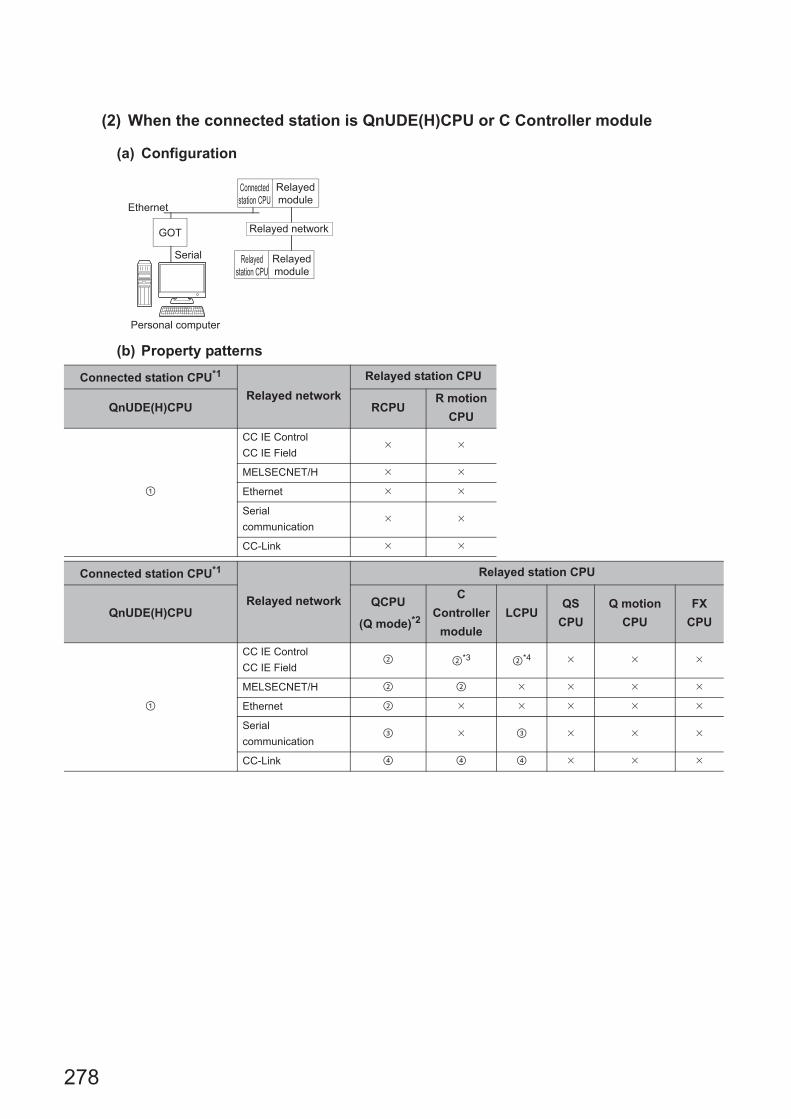
278
(2) When the connected station is QnUDE(H)CPU or C Controller module
(a) Configuration
(b) Property patterns
Connected station CPU*1
Relayed network
Relayed station CPU
QnUDE(H)CPU RCPUR motion
CPU
CC IE Control
CC IE Field
MELSECNET/H
Ethernet
Serial
communication
CC-Link
Connected station CPU*1
Relayed network
Relayed station CPU
QnUDE(H)CPUQCPU
(Q mode)*2
C
Controller
module
LCPUQS
CPU
Q motion
CPU
FX
CPU
CC IE Control
CC IE Field *3 *4
MELSECNET/H
Ethernet
Serial
communication
CC-Link
Personal computer
Connected
station CPU
Relayed
module
Relayed network
Relayed
station CPU
Relayed
module
GOT
Serial
Ethernet

279
CHAPTER 4 PROPERTY SETTINGS OF COMMUNICATION PATHS
4
4.16 GO
T T
ransparent F
unction Com
munication
4.16.11 P
ersonal com
puter side port: Serial, G
OT
2000/1000 side port: S
erial, C
PU
side port: Ethernet
port
*1 : The communication cannot be established when a remote password is set to the connected station CPU.*2 : Redundant CPU cannot be accessed.*3 : Since CC-Link IE Field Network is not supported, Q12DCCPU-V (Basic mode) relayed by CC-Link IE Field Network cannot be
accessed.*4 : Since CC-Link IE Controller Network is not supported, LCPU relayed by CC-Link IE Controller Network cannot be accessed.*5 : Q24DHCCPU-V and Q24DHCCPU-LS cannot be accessed because the communication route is not supported.
Connected station CPU
Relayed network
Relayed station CPU
C Controller module RCPUR motion
CPU
*5
CC IE Control
CC IE Field
MELSECNET/H
Ethernet
Serial
communication
CC-Link
Connected station CPU
Relayed network
Relayed station CPU
C Controller moduleQCPU
(Q mode)*2
C
Controller
module
LCPUQS
CPU
Q motion
CPU
FX
CPU
*5
CC IE Control
CC IE Field *3 *4
MELSECNET/H
Ethernet
Serial
communication
CC-Link
: Accessible (The number in the circle is the property pattern number.), : Inaccessible

280
(c) Property list
The following table shows the property settings of communication paths. The setting is not necessary for those
properties without description.
Property Default valueProperty pattern
*1
ActBaudRate
19200
(BAUDRATE_
19200)
BAUDRATE_9600, BAUDRATE_19200, BAUDRATE_38400, BAUDRATE_57600,
BAUDRATE_115200
ActCpuType34
(CPU_Q02CPU)CPU type corresponding to target station
ActDestination
IONumber0 (0x00) Fixed to 0 (0x00) Fixed to 0 (0x00)
Target station side
For single CPU
Fixed to
1023 (0x3FF)
For multiple CPUs
Connected CPU:
1023 (0x3FF)
No.1: 992 (0x3E0)
No.2: 993 (0x3E1)
No.3: 994 (0x3E2)
No.4: 995 (0x3E3)
Target station side
For single CPU
Fixed to
1023 (0x3FF)
For multiple CPUs
Connected CPU:
1023 (0x3FF)
No.1: 992 (0x3E0)
No.2: 993 (0x3E1)
No.3: 994 (0x3E2)
No.4: 995 (0x3E3)
ActDidProperty
Bit1 (0x01) Fixed to 1 (0x01) Fixed to 1 (0x01) Fixed to 0 (0x00) Fixed to 0 (0x00)
ActDsidPropertyBit 1 (0x01) Fixed to 1 (0x01) Fixed to 1 (0x01) Fixed to 0 (0x00) Fixed to 0 (0x00)
ActHostAddress 1.1.1.1 Host name or IP address of connected station side module
ActIntelligent
PreferenceBit0 (0x00) Fixed to 0 (0x00) Fixed to 0 (0x00)
Target station
QCPU (Q mode),
C Controller module,
LCPU : 1 (0x01)
Other than the above
: 0 (0x00)
Target station
QCPU (Q mode),
C Controller module,
LCPU : 1 (0x01)
Other than the above
: 0 (0x00)
ActIONumber*2 1023 (0x3FF)
For single CPU
Fixed to
1023 (0x3FF)
For multiple CPUs
Connected CPU:
1023 (0x3FF)
No.1: 992 (0x3E0)
No.2: 993 (0x3E1)
No.3: 994 (0x3E2)
No.4: 995 (0x3E3)
Target station side
For single CPU
Fixed to
1023 (0x3FF)
For multiple CPUs
Connected CPU:
1023 (0x3FF)
No.1: 992 (0x3E0)
No.2: 993 (0x3E1)
No.3: 994 (0x3E2)
No.4: 995 (0x3E3)
Connected station
side module I/O
address
Connected station
side module I/O
address
ActMultiDrop
ChannelNumber*30 (0x00) Fixed to 0 (0x00) Fixed to 0 (0x00)
Multi-drop channel
numberFixed to 0 (0x00)
ActNetwork
Number*40 (0x00) Fixed to 0 (0x00)
Target station side
module network
number
Fixed to 0 (0x00) Fixed to 0 (0x00)
ActPortNumber 1 (PORT_1) Personal computer side COM port number
ActProtocolType
0x04
(PROTOCOL_
SERIAL)
PROTOCOL_SERIAL (0x04)
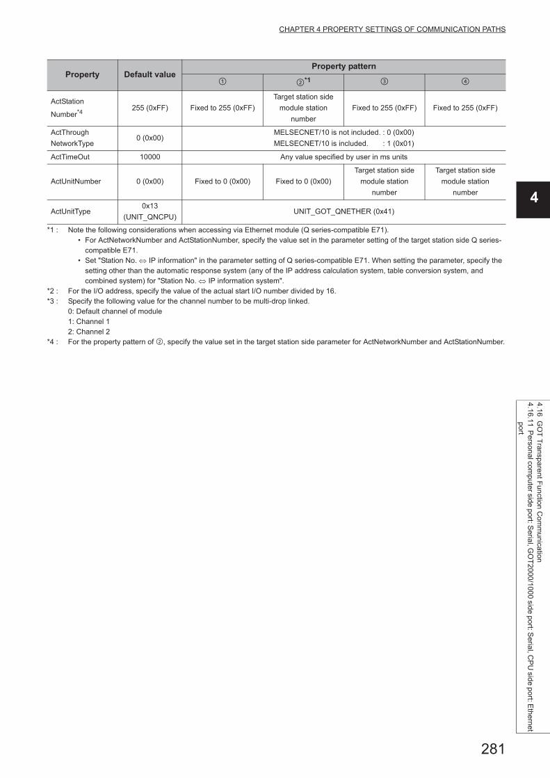
281
CHAPTER 4 PROPERTY SETTINGS OF COMMUNICATION PATHS
4
4.16 GO
T T
ransparent F
unction Com
munication
4.16.11 P
ersonal com
puter side port: Serial, G
OT
2000/1000 side port: S
erial, C
PU
side port: Ethernet
port
*1 : Note the following considerations when accessing via Ethernet module (Q series-compatible E71). • For ActNetworkNumber and ActStationNumber, specify the value set in the parameter setting of the target station side Q series-
compatible E71. • Set "Station No. IP information" in the parameter setting of Q series-compatible E71. When setting the parameter, specify the
setting other than the automatic response system (any of the IP address calculation system, table conversion system, and combined system) for "Station No. IP information system".
*2 : For the I/O address, specify the value of the actual start I/O number divided by 16.*3 : Specify the following value for the channel number to be multi-drop linked.
0: Default channel of module1: Channel 12: Channel 2
*4 : For the property pattern of , specify the value set in the target station side parameter for ActNetworkNumber and ActStationNumber.
ActStation
Number*4255 (0xFF) Fixed to 255 (0xFF)
Target station side
module station
number
Fixed to 255 (0xFF) Fixed to 255 (0xFF)
ActThrough
NetworkType0 (0x00)
MELSECNET/10 is not included. : 0 (0x00)
MELSECNET/10 is included. : 1 (0x01)
ActTimeOut 10000 Any value specified by user in ms units
ActUnitNumber 0 (0x00) Fixed to 0 (0x00) Fixed to 0 (0x00)
Target station side
module station
number
Target station side
module station
number
ActUnitType0x13
(UNIT_QNCPU)UNIT_GOT_QNETHER (0x41)
Property Default valueProperty pattern
*1

282
(3) When the connected station is LCPU
(a) Configuration
(b) Property patterns
*1 : The communication cannot be established when a remote password is set to the connected station CPU.*2 : Redundant CPU cannot be accessed.*3 : Since CC-Link IE Controller Network is not supported, LCPU relayed by CC-Link IE Controller Network cannot be
accessed.*4 : Since CC-Link IE Field Network is not supported, Q12DCCPU-V (Basic mode) relayed by CC-Link IE Field Network
cannot be accessed.
Connected
station CPU*1Relayed network
Relayed station CPU
LCPU RCPUR motion
CPU
CC IE Field*3
MELSECNET/H
Ethernet
Serial
communication
CC-Link
Connected
station CPU*1
Relayed network
Relayed station CPU
LCPUQCPU
(Q mode)*2
C
Controller
module
LCPUQS
CPU
Q motion
CPU
FX
CPU
CC IE Field*3 *4
MELSECNET/H
Ethernet
Serial
communication
CC-Link
: Accessible (The number in the circle is the property pattern number.), : Inaccessible
Personal computer
Connected
station CPU
Relayed
module
Relayed network
Relayed
station CPU
Relayed
module
GOT
Serial
Ethernet

283
CHAPTER 4 PROPERTY SETTINGS OF COMMUNICATION PATHS
4
4.16 GO
T T
ransparent F
unction Com
munication
4.16.11 P
ersonal com
puter side port: Serial, G
OT
2000/1000 side port: S
erial, C
PU
side port: Ethernet
port
(c) Property list
The following table shows the property settings of communication paths. The setting is not necessary for those
properties without description.
Property Default valueProperty pattern
ActBaudRate
19200
(BAUDRATE_
19200)
BAUDRATE_9600, BAUDRATE_19200, BAUDRATE_38400, BAUDRATE_57600,
BAUDRATE_115200
ActControl
8
(TRC_DTR_OR_
RTS)
Depending on used cable.
ActCpuType34
(CPU_Q02CPU)CPU type corresponding to target station
ActDestination
IONumber0 (0x00) Fixed to 0 (0x00)
Target station side
For single CPU
Fixed to
1023 (0x3FF)
For multiple CPUs
Connected CPU:
1023 (0x3FF)
No.1: 992 (0x3E0)
No.2: 993 (0x3E1)
No.3: 994 (0x3E2)
No.4: 995 (0x3E3)
Target station side
For single CPU
Fixed to
1023 (0x3FF)
For multiple CPUs
Connected CPU:
1023 (0x3FF)
No.1: 992 (0x3E0)
No.2: 993 (0x3E1)
No.3: 994 (0x3E2)
No.4: 995 (0x3E3)
Fixed to 0 (0x00)
ActDidPropertyBit 1 (0x01) Fixed to 1 (0x01) Fixed to 0 (0x00) Fixed to 0 (0x00) Fixed to 1 (0x01)
ActDsidPropertyBit 1 (0x01) Fixed to 1 (0x01) Fixed to 0 (0x00) Fixed to 0 (0x00) Fixed to 1 (0x01)
ActHostAddress 1.1.1.1 Host name or IP address of connected station side module
ActIntelligent
PreferenceBit0 (0x00) Fixed to 0 (0x00)
Target station
QCPU (Q mode),
C Controller module,
LCPU : 1 (0x01)
Other than the above
: 0 (0x00)
Target station
QCPU (Q mode),
C Controller module,
LCPU : 1 (0x01)
Other than the above
: 0 (0x00)
Fixed to 0 (0x00)
ActIONumber*1 1023 (0x3FF)Fixed to 1023
(0x3FF)
Connected station side
module I/O address
Connected station side
module I/O address
Target station side
For single CPU
Fixed to
1023 (0x3FF)
For multiple CPUs
Connected CPU:
1023 (0x3FF)
No.1: 992 (0x3E0)
No.2: 993 (0x3E1)
No.3: 994 (0x3E2)
No.4: 995 (0x3E3)
ActMultiDrop
ChannelNumber*20 (0x00) Fixed to 0 (0x00)
Multi-drop channel
numberFixed to 0 (0x00) Fixed to 0 (0x00)
ActNetworkNumber 0 (0x00) Fixed to 0 (0x00) Fixed to 0 (0x00) Fixed to 0 (0x00)
Target station side
module network
number
ActPortNumber 1 (PORT_1) Personal computer side COM port number
ActProtocolType
0x04
(PROTOCOL_
SERIAL)
PROTOCOL_SERIAL (0x04)
ActStationNumber 255 (0xFF)Fixed to 255
(0xFF)Fixed to 255 (0xFF) Fixed to 255 (0xFF)
Target station side
Module Station
number

284
*1 : For the I/O address, specify the value of the actual start I/O number divided by 16.*2 : Specify the following value for the channel number to be multi-drop linked.
0: Default channel of module1: Channel 12: Channel 2
ActThroughNetwork
Type0 (0x00)
MELSECNET/10 is not included. : 0 (0x00)
MELSECNET/10 is included. : 1 (0x01)
ActTimeOut 10000 Any value specified by user in ms units
ActUnitNumber 0 (0x00) Fixed to 0 (0x00)
Target station side
Module Station
number
Target station side
Module Station
number
Fixed to 0 (0x00)
ActUnitType0x13
(UNIT_QNCPU)UNIT_GOT_LNETHER (0x55)
Property Default valueProperty pattern

285
CHAPTER 4 PROPERTY SETTINGS OF COMMUNICATION PATHS
4
4.16 GO
T T
ransparent F
unction Com
munication
4.16.12 P
ersonal computer side port: U
SB
, GO
T2000/1000 side p
ort: US
B, C
PU
side port: Ethernet
port
4.16.12 Personal computer side port: USB, GOT2000/1000 side port: USB, CPU side port: Ethernet port
(1) When the connected station is RCPU
(a) Configuration
(b) Property patterns
*1 : Relayed stations cannot be accessed via R motion CPU.*2 : Since CC-Link IE Controller Network is not supported, RCPU relayed by CC-Link IE Controller Network cannot be accessed.*3 : Only CPU No.2 or later in a multiple CPU configuration can be accessed.
Connected station CPURelayed
network
Relayed station CPU
RCPUR motion
CPURCPU
R motion
CPU
*1,*3
CC IE Control
CC IE Field*2
MELSECNET/H
Ethernet
Serial
communication
CC-Link
Connected station CPU
Relayed
network
Relayed station CPU
RCPUR motion
CPU
QCPU
(Q mode)
C
Controller
module
LCPUQS
CPU
Q motion
CPU
FX
CPU
*1,*3
CC IE Control
CC IE Field
MELSECNET/H
Ethernet
Serial
communication
CC-Link
: Accessible (The number in the circle is the property pattern number.), : Inaccessible
GOT
USB
Ethernet
Personal computer
Connected
station CPU
Relayed
module
Relayed network
Relayed
station CPU
Relayed
module

286
(c) Property list
The following table shows the property settings of communication paths. The setting is not necessary for those
properties without description.
Property Default valueProperty pattern
*1
ActCpuType34
(CPU_Q02CPU)CPU type corresponding to target station
ActDestination
IONumber *20 (0x00) Fixed to 0 (0x00) Fixed to 0 (0x00)
Target station side
For single CPU
Fixed to
1023 (0x3FF)
For multiple CPUs
Connected CPU:
1023 (0x3FF)
No.1: 992 (0x3E0)
No.2: 993 (0x3E1)
No.3: 994 (0x3E2)
No.4: 995 (0x3E3)
Target station side
For single CPU
Fixed to
1023 (0x3FF)
For multiple CPUs
Connected CPU:
1023 (0x3FF)
No.1: 992 (0x3E0)
No.2: 993 (0x3E1)
No.3: 994 (0x3E2)
No.4: 995 (0x3E3)
ActDidPropertyBit 1 (0x01) Fixed to 1 (0x01) Fixed to 1 (0x01) Fixed to 0 (0x00) Fixed to 0 (0x00)
ActDsidPropertyBit 1 (0x01) Fixed to 1 (0x01) Fixed to 1 (0x01) Fixed to 0 (0x00) Fixed to 0 (0x00)
ActHostAddress 1.1.1.1 Host name or IP address of connected station side module
ActIntelligent
PreferenceBit0 (0x00) Fixed to 0 (0x00) Fixed to 0 (0x00)
Target station
RCPU,
QCPU (Q mode),
C Controller module,
LCPU : 1 (0x01)
Other than the
above : 0 (0x00)
Target station
RCPU,
QCPU (Q mode),
C Controller module,
LCPU : 1 (0x01)
Other than the
above : 0 (0x00)
ActIONumber *2 1023 (0x3FF)
For single CPU
Fixed to
1023 (0x3FF)
For multiple CPUs
Connected CPU:
1023 (0x3FF)
No.1: 992 (0x3E0)
No.2: 993 (0x3E1)
No.3: 994 (0x3E2)
No.4: 995 (0x3E3)
Target station side
For single CPU
Fixed to
1023 (0x3FF)
For multiple CPUs
Connected CPU:
1023 (0x3FF)
No.1: 992 (0x3E0)
No.2: 993 (0x3E1)
No.3: 994 (0x3E2)
No.4: 995 (0x3E3)
Connected station
side module I/O
address
Connected station
side module I/O
address
ActMultiDrop
ChannelNumber *30 (0x00) Fixed to 0 (0x00) Fixed to 0 (0x00)
Multi-drop channel
numberFixed to 0 (0x00)
ActNetworkNumber *4 0 (0x00) Fixed to 0 (0x00)
Target station side
module network
number
Fixed to 0 (0x00) Fixed to 0 (0x00)
ActProtocolType
0x04
(PROTOCOL_
SERIAL)
PROTOCOL_USBGOT
ActPacketType0x01
(PACKET_PLC1)PACKET_PLC1
ActConnectUnit
Number0(0x00) Fixed to 0 (0x00)
ActPortNumber 1(PORT_1) Fixed to 0 (0x00)

287
CHAPTER 4 PROPERTY SETTINGS OF COMMUNICATION PATHS
4
4.16 GO
T T
ransparent F
unction Com
munication
4.16.12 P
ersonal computer side port: U
SB
, GO
T2000/1000 side p
ort: US
B, C
PU
side port: Ethernet
port
*1 : When accessing via Ethernet module (R series-compatible E71), consider the following: • For ActNetworkNumber and ActStationNumber, specify the value set to R series-compatible E71 parameter settings on the target
station side. • Set "MNET/10 routing information" to R series-compatible E71 parameter setting. When setting parameters,
specify other than Automatic Response System (either of IP address calculation system, table conversion system, or combined system) for "MNET/H routing information".
*2 : For the I/O address, specify the value of the actual start I/O number divided by 16.*3 : Specify the following value for the channel number to be multi-drop linked.
0: Default channel of module1: Channel 12: Channel 2
*4 : For the property pattern of , specify the value set in the target station side parameter for ActNetworkNumber and ActStationNumber.
ActBaudRate
19200
(BAUDRATE_
19200)
Fixed to 0 (0x00)
ActCpuTimeOut 0(0x00) Fixed to 0 (0x00)
ActControl8(TRC_DTR_
OR_RTS)Fixed to 0 (0x00)
ActDataBits 8(DATABIT_8) Fixed to 0 (0x00)
ActParity 1(ODD_PARITY) Fixed to 0 (0x00)
ActStopBits0(STOPBIT_
ONE)Fixed to 0 (0x00)
ActSumCheck0(NO_SUM_
CHECK)Fixed to 0 (0x00)
ActSourceNetwork
Number0(0x00) Fixed to 0 (0x00)
ActSourceStation
Number0(0x00) Fixed to 0 (0x00)
ActDestinationPort
Number0(0x00) 5006
ActStationNumber *4 255 (0xFF) Fixed to 255 (0xFF)
Target station side
module station
number
Fixed to 255 (0xFF) Fixed to 255 (0xFF)
ActThroughNetwork
Type0 (0x00)
MELSECNET/10 is not included. : 0 (0x00)
MELSECNET/10 is included. : 1 (0x01)
ActTimeOut 10000 Any value specified by user in ms units
ActUnitNumber 0 (0x00) Fixed to 0 (0x00) Fixed to 0 (0x00)
Target station side
module station
number
Target station side
module station
number
ActUnitType0x13
(UNIT_QNCPU)UNIT_GOT_RETHER
Property Default valueProperty pattern
*1

288
(2) When the connected station is QCPU (Q mode) or C Controller module
(a) Configuration
(b) Property patterns
Connected
station CPU*1
Relayed network
Relayed station CPU
QnUDE(H)CPU RCPUR motion
CPU
CC IE Control
CC IE Field
MELSECNET/H
Ethernet
Serial
communication
CC-Link
Connected
station CPU*1
Relayed network
Relayed station CPU
QnUDE(H)CPUQCPU
(Q mode)*2
C
Controller
module
LCPUQS
CPU
Q motion
CPU
FX
CPU
CC IE Control
CC IE Field *3 *4
MELSECNET/H
Ethernet
Serial
communication
CC-Link
GOT
USB
Ethernet
Personal computer
Connected
station CPU
Relayed
module
Relayed network
Relayed
station CPU
Relayed
module

289
CHAPTER 4 PROPERTY SETTINGS OF COMMUNICATION PATHS
4
4.16 GO
T T
ransparent F
unction Com
munication
4.16.12 P
ersonal computer side port: U
SB
, GO
T2000/1000 side p
ort: US
B, C
PU
side port: Ethernet
port
*1 : The communication cannot be established when a remote password is set to the connected station CPU.*2 : Redundant CPU cannot be accessed.*3 : Since CC-Link IE Field Network is not supported, Q12DCCPU-V (Basic mode) relayed by CC-Link IE Field Network
cannot be accessed.*4 : Since CC-Link IE Controller Network is not supported, LCPU relayed by CC-Link IE Controller Network cannot be
accessed.
Connected
station CPU*1
Relayed network
Relayed station CPU
C Controller
moduleRCPU
R motion
CPU
CC IE Control
CC IE Field
MELSECNET/H
Ethernet
Serial
communication
CC-Link
Connected
station CPU*1
Relayed network
Relayed station CPU
C Controller
module
QCPU
(Q mode)*2
C
Controller
module
LCPUQS
CPU
Q motion
CPU
FX
CPU
CC IE Control
CC IE Field *3 *4
MELSECNET/H
Ethernet
Serial
communication
CC-Link
: Accessible (The number in the circle is the property pattern number.), : Inaccessible

290
(c) Property list
The following table shows the property settings of communication paths. The setting is not necessary for those
properties without description.
Property Default valueProperty pattern
*1
ActCpuType34
(CPU_Q02CPU)CPU type corresponding to target station
ActDestination
IONumber0 (0x00) Fixed to 0 (0x00) Fixed to 0 (0x00)
Target station side
For single CPU
Fixed to
1023 (0x3FF)
For multiple CPUs
Connected CPU:
1023 (0x3FF)
No.1: 992 (0x3E0)
No.2: 993 (0x3E1)
No.3: 994 (0x3E2)
No.4: 995 (0x3E3)
Target station side
For single CPU
Fixed to
1023 (0x3FF)
For multiple CPUs
Connected CPU:
1023 (0x3FF)
No.1: 992 (0x3E0)
No.2: 993 (0x3E1)
No.3: 994 (0x3E2)
No.4: 995 (0x3E3)
ActDidProperty
Bit1 (0x01) Fixed to 1 (0x01) Fixed to 1 (0x01) Fixed to 0 (0x00) Fixed to 0 (0x00)
ActDsidProperty
Bit1 (0x01) Fixed to 1 (0x01) Fixed to 1 (0x01) Fixed to 0 (0x00) Fixed to 0 (0x00)
ActHostAddress 1.1.1.1 Host name or IP address of connected station side module
ActIntelligent
PreferenceBit0 (0x00) Fixed to 0 (0x00) Fixed to 0 (0x00)
Target station
QCPU (Q mode),
C Controller module,
LCPU : 1 (0x01)
Other than the above
: 0 (0x00)
Target station
QCPU (Q mode),
C Controller module,
LCPU : 1 (0x01)
Other than the above
: 0 (0x00)
ActIONumber*2 1023 (0x3FF)
For single CPU
Fixed to
1023 (0x3FF)
For multiple CPUs
Connected CPU:
1023 (0x3FF)
No.1: 992 (0x3E0)
No.2: 993 (0x3E1)
No.3: 994 (0x3E2)
No.4: 995 (0x3E3)
Target station side
For single CPU
Fixed to
1023 (0x3FF)
For multiple CPUs
Connected CPU:
1023 (0x3FF)
No.1: 992 (0x3E0)
No.2: 993 (0x3E1)
No.3: 994 (0x3E2)
No.4: 995 (0x3E3)
Connected station
side module I/O
address
Connected station
side module I/O
address
ActMultiDrop
ChannelNumber*30 (0x00) Fixed to 0 (0x00) Fixed to 0 (0x00)
Multi-drop channel
numberFixed to 0 (0x00)
ActNetwork
Number*40 (0x00) Fixed to 0 (0x00)
Target station side
module network
number
Fixed to 0 (0x00) Fixed to 0 (0x00)
ActProtocolType
0x04
(PROTOCOL_
SERIAL)
PROTOCOL_USBGOT (0x13)
ActStation
Number*4255 (0xFF) Fixed to 255 (0xFF)
Target station side
Module Station
number
Fixed to 255 (0xFF) Fixed to 255 (0xFF)
ActThrough
NetworkType0 (0x00)
MELSECNET/10 is not included. : 0 (0x00)
MELSECNET/10 is included. : 1 (0x01)

291
CHAPTER 4 PROPERTY SETTINGS OF COMMUNICATION PATHS
4
4.16 GO
T T
ransparent F
unction Com
munication
4.16.12 P
ersonal computer side port: U
SB
, GO
T2000/1000 side p
ort: US
B, C
PU
side port: Ethernet
port
*1 : Note the following considerations when accessing via Ethernet module (Q series-compatible E71). • For ActNetworkNumber and ActStationNumber, specify the value set in the parameter setting of the target station side Q series-
compatible E71. • Set "Station No. IP information" in the parameter setting of Q series-compatible E71. When setting the parameter, specify the
setting other than the automatic response system (any of the IP address calculation system, table conversion system, and combined system) for "Station No. IP information system".
*2 : For the I/O address, specify the value of the actual start I/O number divided by 16.*3 : Specify the following value for the channel number to be multi-drop linked.
0: Default channel of module1: Channel 12: Channel 2
*4 : For the property pattern of , specify the value set in the target station side parameter for ActNetworkNumber and ActStationNumber.
ActTimeOut 10000 Any value specified by user in ms units
ActUnitNumber 0 (0x00) Fixed to 0 (0x00) Fixed to 0 (0x00)
Target station side
Module Station
number
Target station side
Module Station
number
ActUnitType0x13
(UNIT_QNCPU)UNIT_GOT_QNETHER (0x41)
Property Default valueProperty pattern
*1

292
(3) When the connected station is LCPU
(a) Configuration
(b) Property patterns
*1 : The communication cannot be established when a remote password is set to the connected station CPU.*2 : Redundant CPU cannot be accessed.*3 : Since CC-Link IE Controller Network is not supported, LCPU relayed by CC-Link IE Controller Network cannot be
accessed.*4 : Since CC-Link IE Field Network is not supported, Q12DCCPU-V (Basic mode) relayed by CC-Link IE Field Network
cannot be accessed.
Connected
station CPU*1
Relayed network
Relayed station CPU
LCPU RCPUR motion
CPU
CC IE Field*3
MELSECNET/H
Ethernet
Serial
communication
CC-Link
Connected
station CPU*1
Relayed network
Relayed station CPU
LCPUQCPU
(Q mode)*2
C
Controller
module
LCPUQS
CPU
Q motion
CPU
FX
CPU
CC IE Field*3 *4
MELSECNET/H
Ethernet
Serial
communication
CC-Link
: Accessible (The number in the circle is the property pattern number.), : Inaccessible
GOT
USB
Ethernet
Personal computer
Connected
station CPU
Relayed
module
Relayed network
Relayed
station CPU
Relayed
module

293
CHAPTER 4 PROPERTY SETTINGS OF COMMUNICATION PATHS
4
4.16 GO
T T
ransparent F
unction Com
munication
4.16.12 P
ersonal computer side port: U
SB
, GO
T2000/1000 side p
ort: US
B, C
PU
side port: Ethernet
port
(c) Property list
The following table shows the property settings of communication paths. The setting is not necessary for those
properties without description.
Property Default valueProperty pattern
ActCpuType34
(CPU_Q02CPU)CPU type corresponding to target station
ActDestination
IONumber0 (0x00) Fixed to 0 (0x00)
Target station side
For single CPU
Fixed to
1023 (0x3FF)
For multiple CPUs
Connected CPU:
1023 (0x3FF)
No.1: 992 (0x3E0)
No.2: 993 (0x3E1)
No.3: 994 (0x3E2)
No.4: 995 (0x3E3)
Target station side
For single CPU
Fixed to
1023 (0x3FF)
For multiple CPUs
Connected CPU:
1023 (0x3FF)
No.1: 992 (0x3E0)
No.2: 993 (0x3E1)
No.3: 994 (0x3E2)
No.4: 995 (0x3E3)
Fixed to 0 (0x00)
ActDidPropertyBit 1 (0x01) Fixed to 1 (0x01) Fixed to 0 (0x00) Fixed to 0 (0x00) Fixed to 1 (0x01)
ActDsidPropertyBit 1 (0x01) Fixed to 1 (0x01) Fixed to 0 (0x00) Fixed to 0 (0x00) Fixed to 1 (0x01)
ActHostAddress 1.1.1.1 Host name or IP address of connected station side module
ActIntelligent
PreferenceBit0 (0x00) Fixed to 0 (0x00) Fixed to 0 (0x00)
Target station
QCPU (Q mode),
C Controller module,
LCPU : 1 (0x01)
Other than the above
: 0 (0x00)
Target station
QCPU (Q mode),
C Controller module,
LCPU : 1 (0x01)
Other than the above
: 0 (0x00)
ActIONumber*1 1023 (0x3FF)Fixed to 1023
(0x3FF)
Connected station side
module I/O address
Connected station side
module I/O address
Target station side
For single CPU
Fixed to
1023 (0x3FF)
For multiple CPUs
Connected CPU:
1023 (0x3FF)
No.1: 992 (0x3E0)
No.2: 993 (0x3E1)
No.3: 994 (0x3E2)
No.4: 995 (0x3E3)
ActMultiDrop
ChannelNumber*20 (0x00) Fixed to 0 (0x00)
Multi-drop channel
numberFixed to 0 (0x00) Fixed to 0 (0x00)
ActNetworkNumber 0 (0x00) Fixed to 0 (0x00) Fixed to 0 (0x00) Fixed to 0 (0x00)
Target station side
module network
number
ActProtocolType
0x04
(PROTOCOL_
SERIAL)
PROTOCOL_USBGOT (0x13)
ActStationNumber 255 (0xFF)Fixed to 255
(0xFF)Fixed to 255 (0xFF) Fixed to 255 (0xFF)
Target station side
Module Station
number
ActThrough
NetworkType0 (0x00)
MELSECNET/10 is not included. : 0 (0x00)
MELSECNET/10 is included. : 1 (0x01)
ActTimeOut 10000 Any value specified by user in ms units

294
*1 : For the I/O address, specify the value of the actual start I/O number divided by 16.*2 : Specify the following value for the channel number to be multi-drop linked.
0: Default channel of module1: Channel 12: Channel 2
ActUnitNumber 0 (0x00) Fixed to 0 (0x00)
Target station side
Module Station
number
Target station side
Module Station
number
Fixed to 0 (0x00)
ActUnitType0x13
(UNIT_QNCPU)UNIT_GOT_LNETHER (0x55)
Property Default valueProperty pattern

295
CHAPTER 4 PROPERTY SETTINGS OF COMMUNICATION PATHS
4
4.16 GO
T T
ransparent F
unction Com
munication
4.16.13 P
ersonal com
puter side port: Serial, G
OT
2000/1000 side port: S
erial, C
PU
side port: Ethernet
adapter m
odule
4.16.13 Personal computer side port: Serial, GOT2000/1000 side port: Serial, CPU side port: Ethernet adapter module
(1) Configuration
(2) Property patterns
Connected
station CPURelayed network
Relayed station CPU
QnUDE(H)CPU RCPUR motion
CPU
CC IE Control
CC IE Field
MELSECNET/H
Ethernet
Serial
communication
CC-Link
Connected
station CPU
Relayed network
Relayed station CPU
QnUDE(H)CPUQCPU
(Q mode)*1
C
Controller
module
LCPUQS
CPU
Q motion
CPU
FX
CPU
CC IE Control
CC IE Field *2 *3
MELSECNET/H
Ethernet
Serial
communication
CC-Link
Personal computer
Connected
station CPU
Relayed
module
Relayed network
Relayed
station CPU
Relayed
module
GOT
Serial
CC-Link IE Field
Network module
Ethernet
Ethernet Adapter module

296
*1 : Redundant CPU cannot be accessed.*2 : Since CC-Link IE Field Network is not supported, Q12DCCPU-V (Basic mode) relayed by CC-Link IE Field Network
cannot be accessed.*3 : Since CC-Link IE Controller Network is not supported, LCPU relayed by CC-Link IE Controller Network cannot be
accessed.
Connected
station CPURelayed network
Relayed station CPU
LCPU RCPUR motion
CPU
CC IE Field*3
MELSECNET/H
Ethernet
Serial
communication
CC-Link
Connected
station CPU
Relayed network
Relayed station CPU
LCPUQCPU
(Q mode)*1
C
Controller
module
LCPUQS
CPU
Q motion
CPU
FX
CPU
CC IE Field*3 *2
MELSECNET/H
Ethernet
Serial
communication
CC-Link
: Accessible (The number in the circle is the property pattern number.), : Inaccessible

297
CHAPTER 4 PROPERTY SETTINGS OF COMMUNICATION PATHS
4
4.16 GO
T T
ransparent F
unction Com
munication
4.16.13 P
ersonal com
puter side port: Serial, G
OT
2000/1000 side port: S
erial, C
PU
side port: Ethernet
adapter m
odule
(3) Property listThe following table shows the property settings of communication paths. The setting is not necessary for those
properties without description.
Property Default valueProperty pattern
ActBaudRate
19200
(BAUDRATE_
19200)
BAUDRATE_9600, BAUDRATE_19200, BAUDRATE_38400, BAUDRATE_57600,
BAUDRATE_115200
ActCpuType34
(CPU_Q02CPU)CPU type corresponding to target station
ActDestination
IONumber0 (0x00) Fixed to 0 (0x00) Fixed to 0 (0x00)
Target station side
For single CPU
Fixed to
1023 (0x3FF)
For multiple CPUs
Connected CPU:
1023 (0x3FF)
No.1: 992 (0x3E0)
No.2: 993 (0x3E1)
No.3: 994 (0x3E2)
No.4: 995 (0x3E3)
Target station side
For single CPU
Fixed to
1023 (0x3FF)
For multiple CPUs
Connected CPU:
1023 (0x3FF)
No.1: 992 (0x3E0)
No.2: 993 (0x3E1)
No.3: 994 (0x3E2)
No.4: 995 (0x3E3)
ActDidProperty
Bit1 (0x01) Fixed to 1 (0x01) Fixed to 1 (0x01) Fixed to 0 (0x00) Fixed to 0 (0x00)
ActDsidProperty
Bit1 (0x01) Fixed to 1 (0x01) Fixed to 1 (0x01) Fixed to 0 (0x00) Fixed to 0 (0x00)
ActHostAddress 1.1.1.1 Host name or IP address of Ethernet adapter module
ActIntelligent
PreferenceBit0 (0x00) Fixed to 0 (0x00)
ActIONumber*1 1023 (0x3FF)
For single CPU
Fixed to
1023 (0x3FF)
For multiple CPUs
Connected CPU:
1023 (0x3FF)
No.1: 992 (0x3E0)
No.2: 993 (0x3E1)
No.3: 994 (0x3E2)
No.4: 995 (0x3E3)
Target station side
For single CPU
Fixed to
1023 (0x3FF)
For multiple CPUs
Connected CPU:
1023 (0x3FF)
No.1: 992 (0x3E0)
No.2: 993 (0x3E1)
No.3: 994 (0x3E2)
No.4: 995 (0x3E3)
Connected station
side module I/O
address
Connected station
side module I/O
address
ActMultiDrop
ChannelNumber*20 (0x00) Fixed to 0 (0x00) Fixed to 0 (0x00)
Multi-drop channel
numberFixed to 0 (0x00)
ActNetwork
Number*30 (0x00)
Connected station
side CC-Link IE Field
Network module
network number
Target station side
module station
number
Connected station
side CC-Link IE Field
Network module
network number
Connected station
side CC-Link IE Field
Network module
network number
ActPortNumber 1 (PORT_1) Personal computer side COM port number
ActProtocolType
0x04
(PROTOCOL_
SERIAL)
PROTOCOL_SERIAL (0x04)
ActStation
Number*3255 (0xFF)
Connected station
side CC-Link IE Field
Network module
station number
Target station side
Module Station
number
Connected station
side CC-Link IE Field
Network module
station number
Connected station
side CC-Link IE Field
Network module
station number

298
*1 : For the I/O address, specify the value of the actual start I/O number divided by 16.*2 : Specify the following value for the channel number to be multi-drop linked.
0: Default channel of module1: Channel 12: Channel 2
*3 : For the property pattern of , or , specify the parameter value set on the CC-Link IE Field Network module on the connected station side for ActNetworkNumber and ActStationNumber.For the property pattern of , specify the value set in the target station side parameter for ActNetworkNumber and ActStationNumber.
ActThrough
NetworkType0 (0x00)
MELSECNET/10 is not included. : 0 (0x00)
MELSECNET/10 is included. : 1 (0x01)
ActTimeOut 10000 Any value specified by user in ms units
ActUnitNumber 0 (0x00) Fixed to 0 (0x00) Fixed to 0 (0x00)
Target station side
Module Station
number
Target station side
Module Station
number
ActUnitType0x13
(UNIT_QNCPU)UNIT_GOT_NZ2GF_ETB (0x5B)
Property Default valueProperty pattern

299
CHAPTER 4 PROPERTY SETTINGS OF COMMUNICATION PATHS
4
4.16 GO
T T
ransparent F
unction Com
munication
4.16.14 P
ersonal computer side port: U
SB
, GO
T2000/1000 side p
ort: US
B, C
PU
side port: Ethernet
adapter m
odule
4.16.14 Personal computer side port: USB, GOT2000/1000 side port: USB, CPU side port: Ethernet adapter module
(1) Configuration
(2) Property patterns
Connected
station CPURelayed network
Relayed station CPU
QnUDE(H)CPU RCPUR motion
CPU
CC IE Control
CC IE Field
MELSECNET/H
Ethernet
Serial
communication
CC-Link
Connected
station CPU
Relayed network
Relayed station CPU
QnUDE(H)CPUQCPU
(Q mode)*1
C
Controller
module
LCPUQS
CPU
Q motion
CPU
FX
CPU
CC IE Control
CC IE Field *2 *3
MELSECNET/H
Ethernet
Serial
communication
CC-Link
GOT
USB
Ethernet
Personal computer
Connected
station CPU
Relayed
module
Relayed network
Relayed
station CPU
Relayed
module
CC-Link IE Field
Network module
Ethernet Adapter module

300
*1 : Redundant CPU cannot be accessed.*2 : Since CC-Link IE Field Network is not supported, Q12DCCPU-V (Basic mode) relayed by CC-Link IE Field Network
cannot be accessed.*3 : Since CC-Link IE Controller Network is not supported, LCPU relayed by CC-Link IE Controller Network cannot be
accessed.
Connected
station CPURelayed network
Relayed station CPU
LCPU RCPUR motion
CPU
CC IE Field*3
MELSECNET/H
Ethernet
Serial
communication
CC-Link
Connected
station CPU
Relayed network
Relayed station CPU
LCPUQCPU
(Q mode)*1
C
Controller
module
LCPUQS
CPU
Q motion
CPU
FX
CPU
CC IE Field*3
MELSECNET/H
Ethernet
Serial
communication
CC-Link
: Accessible (The number in the circle is the property pattern number.), : Inaccessible

301
CHAPTER 4 PROPERTY SETTINGS OF COMMUNICATION PATHS
4
4.16 GO
T T
ransparent F
unction Com
munication
4.16.14 P
ersonal computer side port: U
SB
, GO
T2000/1000 side p
ort: US
B, C
PU
side port: Ethernet
adapter m
odule
(3) Property listThe following table shows the property settings of communication paths. The setting is not necessary for those
properties without description.
Property Default valueProperty pattern
ActCpuType34
(CPU_Q02CPU)CPU type corresponding to target station
ActDestination
IONumber0 (0x00) Fixed to 0 (0x00) Fixed to 0 (0x00)
Target station side
For single CPU
Fixed to
1023 (0x3FF)
For multiple CPUs
Connected CPU:
1023 (0x3FF)
No.1: 992 (0x3E0)
No.2: 993 (0x3E1)
No.3: 994 (0x3E2)
No.4: 995 (0x3E3)
Target station side
For single CPU
Fixed to
1023 (0x3FF)
For multiple CPUs
Connected CPU:
1023 (0x3FF)
No.1: 992 (0x3E0)
No.2: 993 (0x3E1)
No.3: 994 (0x3E2)
No.4: 995 (0x3E3)
ActDidProperty
Bit1 (0x01) Fixed to 1 (0x01) Fixed to 1 (0x01) Fixed to 0 (0x00) Fixed to 0 (0x00)
ActDsidProperty
Bit1 (0x01) Fixed to 1 (0x01) Fixed to 1 (0x01) Fixed to 0 (0x00) Fixed to 0 (0x00)
ActHostAddress 1.1.1.1 Host name or IP address of Ethernet adapter module
ActIntelligent
PreferenceBit0 (0x00) Fixed to 0 (0x00)
ActIONumber*1 1023 (0x3FF)
For single CPU
Fixed to
1023 (0x3FF)
For multiple CPUs
Connected CPU:
1023 (0x3FF)
No.1: 992 (0x3E0)
No.2: 993 (0x3E1)
No.3: 994 (0x3E2)
No.4: 995 (0x3E3)
Target station side
For single CPU
Fixed to
1023 (0x3FF)
For multiple CPUs
Connected CPU:
1023 (0x3FF)
No.1: 992 (0x3E0)
No.2: 993 (0x3E1)
No.3: 994 (0x3E2)
No.4: 995 (0x3E3)
Connected station
side module I/O
address
Connected station
side module I/O
address
ActMultiDrop
ChannelNumber*20 (0x00) Fixed to 0 (0x00) Fixed to 0 (0x00)
Multi-drop channel
numberFixed to 0 (0x00)
ActNetwork
Number*30 (0x00)
Connected station
side CC-Link IE Field
Network module
network number
Target station side
module station
number
Connected station
side CC-Link IE Field
Network module
network number
Connected station
side CC-Link IE Field
Network module
network number
ActProtocolType
0x04
(PROTOCOL_
SERIAL)
PROTOCOL_USBGOT (0x13)
ActStation
Number*3255 (0xFF)
Connected station
side CC-Link IE Field
Network module
station number
Target station side
Module Station
number
Connected station
side CC-Link IE Field
Network module
station number
Connected station
side CC-Link IE Field
Network module
station number
ActThrough
NetworkType0 (0x00)
MELSECNET/10 is not included. : 0 (0x00)
MELSECNET/10 is included. : 1 (0x01)
ActTimeOut 10000 Any value specified by user in ms units

302
*1 : For the I/O address, specify the value of the actual start I/O number divided by 16.*2 : Specify the following value for the channel number to be multi-drop linked.
0: Default channel of module1: Channel 12: Channel 2
*3 : For the property pattern of , or , specify the parameter value set on the CC-Link IE Field Network module on the connected station side for ActNetworkNumber and ActStationNumber.For the property pattern of , specify the value set in the target station side parameter for ActNetworkNumber and ActStationNumber.
ActUnitNumber 0 (0x00) Fixed to 0 (0x00) Fixed to 0 (0x00)
Target station side
Module Station
number
Target station side
Module Station
number
ActUnitType0x13
(UNIT_QNCPU)UNIT_GOT_NZ2GF_ETB (0x5B)
Property Default valueProperty pattern

303
CHAPTER 4 PROPERTY SETTINGS OF COMMUNICATION PATHS
4
4.16 GO
T T
ransparent F
unction Com
munication
4.16.15 P
ersonal com
puter side port: Serial, G
OT
2000/1000 side port: S
erial, C
PU
side port: Ethernet
adapter/m
odule
4.16.15 Personal computer side port: Serial, GOT2000/1000 side port: Serial, CPU side port: Ethernet adapter/module
(1) When the connected station is FXCPU
(a) Configuration
(b) Property patterns
*1 : Only FX3SCPU(FX3U-ENET-ADP), FX3G(C)CPU and FX3U(C)CPU can be accessed.
Ethernet adapter: FX3U-ENET-ADP Ethernet module: FX3U-ENET (-L)
Connected
station CPURelayed network
Relayed station CPU
FXCPU RCPUR motion
CPU
*1
CC IE Control
CC IE Field
MELSECNET/H
Ethernet
Serial
communication
CC-Link
Connected
station CPURelayed network
Relayed station CPU
FXCPUQCPU
(Q mode)
C Controller
moduleLCPU
QS
CPU
Q motion
CPU
FX
CPU
*1
CC IE Control
CC IE Field
MELSECNET/H
Ethernet
Serial
communication
CC-Link
: Accessible (The number in the circle is the property pattern number.), : Inaccessible
GOT
Ethernet
Serial
Ethernet adapter
Connectedstation CPU
Relayedmodule
Relayed network
Relayedmodule
Relayedstation CPU
Personal computer
Ethernet
GOT
Relayedmodule
Relayed network
Relayedmodule
Relayedstation CPU
Personal computer
Serial
Ethernet module
Connectedstation CPU

304
(c) Property list
The following table shows the property settings of communication paths. The setting is not necessary for those
properties without description.
Property Default valueProperty pattern
ActBaudRate19200
(BAUDRATE_19200)
BAUDRATE_9600, BAUDRATE_19200, BAUDRATE_38400,
BAUDRATE_57600, BAUDRATE_115200
ActControl8
(TRC_DTR_OR_RTS)Depending on used cable
ActCpuType34
(CPU_Q02CPU)CPU type corresponding to the target station
ActHostAddress 1.1.1.1Host name or IP address of FX3U-ENET-ADP module
Host name or IP address of FX3U-ENET (-L) module
ActPortNumber 1 (PORT_1) Personal computer side COM port number
ActProtocolType0x04
(PROTOCOL_SERIAL)PROTOCOL_SERIAL
ActTimeOut 10000 Any value specified by user in ms units
ActUnitType0x13
(UNIT_QNCPU)
FX3U-ENET-ADP: UNIT_GOT_FXETHER
FX3U-ENET(-L): UNIT_GOT_FXENET

305
CHAPTER 4 PROPERTY SETTINGS OF COMMUNICATION PATHS
4
4.16 GO
T T
ransparent F
unction Com
munication
4.16.16 P
ersonal computer side port: U
SB
, GO
T2000/1000 side p
ort: US
B, C
PU
side port: Ethernet
adapter/m
odule
4.16.16 Personal computer side port: USB, GOT2000/1000 side port: USB, CPU side port: Ethernet adapter/module
(1) When the connected station is FXCPU
(a) Configuration
(b) Property patterns
*1 : Only FX3SCPU(FX3U-ENET-ADP), FX3G(C)CPU and FX3U(C)CPU can be accessed.
Ethernet adapter: FX3U-ENET-ADP Ethernet module: FX3U-ENET (-L)
Connected
station CPURelayed network
Relayed station CPU
FXCPU RCPUR motion
CPU
*1
CC IE Control
CC IE Field
MELSECNET/H
Ethernet
Serial
communication
CC-Link
Connected
station CPURelayed network
Relayed station CPU
FXCPUQCPU
(Q mode)
C Controller
moduleLCPU
QS
CPU
Q motion
CPU
FX
CPU
*1
CC IE Control
CC IE Field
MELSECNET/H
Ethernet
Serial
communication
CC-Link
: Accessible (The number in the circle is the property pattern number.), : Inaccessible
GOT
Ethernet
USB
Ethernet adapter
Connectedstation CPU
Relayedmodule
Relayed network
Relayedmodule
Relayedstation CPU
Personal computer
Ethernet
GOT
Relayedmodule
Relayed network
Relayedmodule
Relayedstation CPU
Personal computer
USB
Ethernet module
Connectedstation CPU

306
(c) Property list
The following table shows the property settings of communication paths. The setting is not necessary for those
properties without description.
Property Default valueProperty pattern
ActCpuType34
(CPU_Q02CPU)CPU type corresponding to the target station
ActHostAddress 1.1.1.1Host name or IP address of FX3U-ENET-ADP module
Host name or IP address of FX3U-ENET (-L) module
ActProtocolType0x04
(PROTOCOL_SERIAL)PROTOCOL_SERIAL
ActTimeOut 10000 Any value specified by user in ms units
ActUnitType0x13
(UNIT_QNCPU)
FX3U-ENET-ADP: UNIT_GOT_FXETHER
FX3U-ENET(-L): UNIT_GOT_FXENET

307
CHAPTER 4 PROPERTY SETTINGS OF COMMUNICATION PATHS
4
4.16 GO
T T
ransparent F
unction Com
munication
4.16.17 P
ersonal com
puter side port: Ethe
rnet port, GO
T2
000/1000 side port: E
thernet port, CP
U side
port: S
erial
4.16.17 Personal computer side port: Ethernet port, GOT2000/1000 side port: Ethernet port, CPU side port: Serial
(1) When the connected station is QCPU (Q mode) or C Controller module
(a) Configuration
(b) Property patterns
*1 : Redundant CPU cannot be accessed.*2 : Since CC-Link IE Field Network is not supported, Q12DCCPU-V (Basic mode) relayed by CC-Link IE Field Network cannot be
accessed.*3 : Since CC-Link IE Controller Network is not supported, LCPU relayed by CC-Link IE Controller Network cannot be accessed.*4 : For Q24DHCCPU-V and Q24DHCCPU-LS, only CPU No.2 or later in a multiple CPU configuration can be accessed.
Connected station CPURelayed
network
Relayed station CPU
QCPU
(Q mode)
C Controller
moduleRCPU
R motion
CPU
*1 *4
CC IE Control
CC IE Field
MELSECNET/H
Ethernet
Serial
communication
CC-Link
Connected station CPU
Relayed
network
Relayed station CPU
QCPU
(Q mode)
C Controller
module
QCPU
(Q mode)*1
C
Controller
module
LCPUQS
CPU
Q motion
CPU
FX
CPU
*1 *4
CC IE Control
CC IE Field *2 *3
MELSECNET/H
Ethernet
Serial
communication
CC-Link
: Accessible (The number in the circle is the property pattern number.), : Inaccessible
Personal computer
Connected
station CPU
Relayed
module
Relayed network
Relayed
station CPU
Relayed
module
GOT
Ethernet
Serial
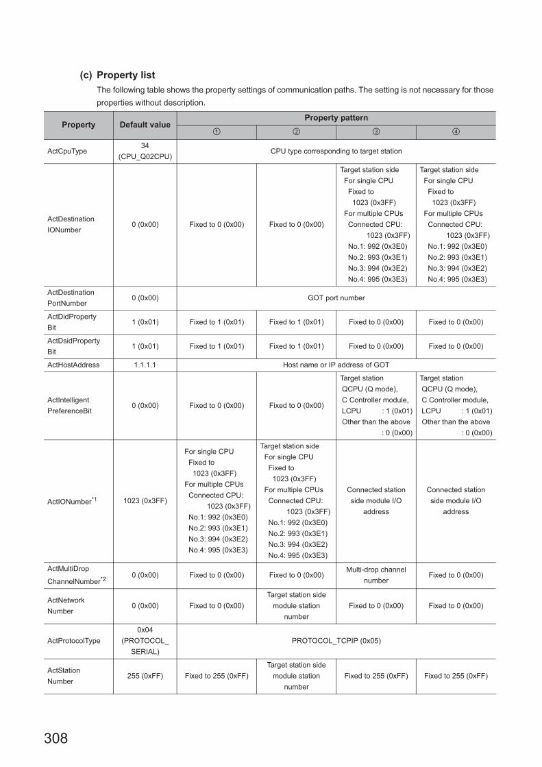
308
(c) Property list
The following table shows the property settings of communication paths. The setting is not necessary for those
properties without description.
Property Default valueProperty pattern
ActCpuType34
(CPU_Q02CPU)CPU type corresponding to target station
ActDestination
IONumber0 (0x00) Fixed to 0 (0x00) Fixed to 0 (0x00)
Target station side
For single CPU
Fixed to
1023 (0x3FF)
For multiple CPUs
Connected CPU:
1023 (0x3FF)
No.1: 992 (0x3E0)
No.2: 993 (0x3E1)
No.3: 994 (0x3E2)
No.4: 995 (0x3E3)
Target station side
For single CPU
Fixed to
1023 (0x3FF)
For multiple CPUs
Connected CPU:
1023 (0x3FF)
No.1: 992 (0x3E0)
No.2: 993 (0x3E1)
No.3: 994 (0x3E2)
No.4: 995 (0x3E3)
ActDestination
PortNumber0 (0x00) GOT port number
ActDidProperty
Bit1 (0x01) Fixed to 1 (0x01) Fixed to 1 (0x01) Fixed to 0 (0x00) Fixed to 0 (0x00)
ActDsidProperty
Bit1 (0x01) Fixed to 1 (0x01) Fixed to 1 (0x01) Fixed to 0 (0x00) Fixed to 0 (0x00)
ActHostAddress 1.1.1.1 Host name or IP address of GOT
ActIntelligent
PreferenceBit0 (0x00) Fixed to 0 (0x00) Fixed to 0 (0x00)
Target station
QCPU (Q mode),
C Controller module,
LCPU : 1 (0x01)
Other than the above
: 0 (0x00)
Target station
QCPU (Q mode),
C Controller module,
LCPU : 1 (0x01)
Other than the above
: 0 (0x00)
ActIONumber*1 1023 (0x3FF)
For single CPU
Fixed to
1023 (0x3FF)
For multiple CPUs
Connected CPU:
1023 (0x3FF)
No.1: 992 (0x3E0)
No.2: 993 (0x3E1)
No.3: 994 (0x3E2)
No.4: 995 (0x3E3)
Target station side
For single CPU
Fixed to
1023 (0x3FF)
For multiple CPUs
Connected CPU:
1023 (0x3FF)
No.1: 992 (0x3E0)
No.2: 993 (0x3E1)
No.3: 994 (0x3E2)
No.4: 995 (0x3E3)
Connected station
side module I/O
address
Connected station
side module I/O
address
ActMultiDrop
ChannelNumber*20 (0x00) Fixed to 0 (0x00) Fixed to 0 (0x00)
Multi-drop channel
numberFixed to 0 (0x00)
ActNetwork
Number0 (0x00) Fixed to 0 (0x00)
Target station side
module station
number
Fixed to 0 (0x00) Fixed to 0 (0x00)
ActProtocolType
0x04
(PROTOCOL_
SERIAL)
PROTOCOL_TCPIP (0x05)
ActStation
Number255 (0xFF) Fixed to 255 (0xFF)
Target station side
module station
number
Fixed to 255 (0xFF) Fixed to 255 (0xFF)

309
CHAPTER 4 PROPERTY SETTINGS OF COMMUNICATION PATHS
4
4.16 GO
T T
ransparent F
unction Com
munication
4.16.17 P
ersonal com
puter side port: Ethe
rnet port, GO
T2
000/1000 side port: E
thernet port, CP
U side
port: S
erial
*1 : For the I/O address, specify the value of the actual start I/O number divided by 16.*2 : Specify the following value for the channel number to be multi-drop linked.
0: Default channel of module1: Channel 12: Channel 2
ActThrough
NetworkType0 (0x00)
MELSECNET/10 is not included. : 0 (0x00)
MELSECNET/10 is included. : 1 (0x01)
ActTimeOut 10000 Any value specified by user in ms units
ActUnitNumber 0 (0x00) Fixed to 0 (0x00) Fixed to 0 (0x00)
Target station side
module station
number
Target station side
module station
number
ActUnitType0x13
(UNIT_QNCPU)UNIT_GOTETHER_QNCPU (0x56)
Property Default valueProperty pattern

310
(2) When the connected station is LCPU
(a) Configuration
(b) Property patterns
*1 : Redundant CPU cannot be accessed.*2 : Since CC-Link IE Controller Network is not supported, LCPU relayed by CC-Link IE Controller Network cannot be
accessed.*3 : Since CC-Link IE Field Network is not supported, Q12DCCPU-V (Basic mode) relayed by CC-Link IE Field Network
cannot be accessed.
Connected
station CPURelayed network
Relayed station CPU
LCPU RCPUR motion
CPU
CC IE Field*2
MELSECNET/H
Ethernet
Serial
communication
CC-Link
Connected
station CPU
Relayed network
Relayed station CPU
LCPUQCPU
(Q mode)*1
C
Controller
module
LCPUQS
CPU
Q motion
CPU
FX
CPU
CC IE Field*2 *3
MELSECNET/H
Ethernet
Serial
communication
CC-Link
: Accessible (The number in the circle is the property pattern number.), : Inaccessible
Personal computer
Connected
station CPU
Relayed
module
Relayed network
Relayed
station CPU
Relayed
module
GOT
Ethernet
Serial

311
CHAPTER 4 PROPERTY SETTINGS OF COMMUNICATION PATHS
4
4.16 GO
T T
ransparent F
unction Com
munication
4.16.17 P
ersonal com
puter side port: Ethe
rnet port, GO
T2
000/1000 side port: E
thernet port, CP
U side
port: S
erial
(c) Property list
The following table shows the property settings of communication paths. The setting is not necessary for those
properties without description.
Property Default valueProperty pattern
ActCpuType34
(CPU_Q02CPU)CPU type corresponding to target station
ActDestination
IONumber0 (0x00) Fixed to 0 (0x00)
Target station side
For single CPU
Fixed to
1023 (0x3FF)
For multiple CPUs
Connected CPU:
1023 (0x3FF)
No.1: 992 (0x3E0)
No.2: 993 (0x3E1)
No.3: 994 (0x3E2)
No.4: 995 (0x3E3)
Target station side
For single CPU
Fixed to
1023 (0x3FF)
For multiple CPUs
Connected CPU:
1023 (0x3FF)
No.1: 992 (0x3E0)
No.2: 993 (0x3E1)
No.3: 994 (0x3E2)
No.4: 995 (0x3E3)
Fixed to 0 (0x00)
ActDestination
PortNumber0 (0x00) GOT port number
ActDidPropertyBit 1 (0x01) Fixed to 1 (0x01) Fixed to 0 (0x00) Fixed to 0 (0x00) Fixed to 1 (0x01)
ActDsidPropertyBit 1 (0x01) Fixed to 1 (0x01) Fixed to 0 (0x00) Fixed to 0 (0x00) Fixed to 1 (0x01)
ActHostAddress 1.1.1.1 Host name or IP address of GOT
ActIntelligent
PreferenceBit0 (0x00) Fixed to 0 (0x00)
Target station
QCPU (Q mode),
C Controller module,
LCPU : 1 (0x01)
Other than the above
: 0 (0x00)
Target station
QCPU (Q mode),
C Controller module,
LCPU : 1 (0x01)
Other than the above
: 0 (0x00)
Fixed to 0 (0x00)
ActIONumber*1 1023 (0x3FF)Fixed to 1023
(0x3FF)
Connected station side
module I/O address
Connected station side
module I/O address
Target station side
For single CPU
Fixed to
1023 (0x3FF)
For multiple CPUs
Connected CPU:
1023 (0x3FF)
No.1: 992 (0x3E0)
No.2: 993 (0x3E1)
No.3: 994 (0x3E2)
No.4: 995 (0x3E3)
ActMultiDrop
ChannelNumber*20 (0x00) Fixed to 0 (0x00)
Multi-drop channel
numberFixed to 0 (0x00) Fixed to 0 (0x00)
ActNetworkNumber 0 (0x00) Fixed to 0 (0x00) Fixed to 0 (0x00) Fixed to 0 (0x00)
Target station side
module network
number
ActProtocolType
0x04
(PROTOCOL_
SERIAL)
PROTOCOL_TCPIP (0x05)
ActStationNumber 255 (0xFF)Fixed to 255
(0xFF)Fixed to 255 (0xFF) Fixed to 255 (0xFF)
Target station side
module station number
ActThroughNetwork
Type0 (0x00)
MELSECNET/10 is not included. : 0 (0x00)
MELSECNET/10 is included. : 1 (0x01)
ActTimeOut 10000 Any value specified by user in ms units

312
*1 : For the I/O address, specify the value of the actual start I/O number divided by 16.*2 : Specify the following value for the channel number to be multi-drop linked.
0: Default channel of module1: Channel 12: Channel 2
ActUnitNumber 0 (0x00) Fixed to 0 (0x00)Target station side
module station number
Target station side
module station numberFixed to 0 (0x00)
ActUnitType0x13
(UNIT_QNCPU)UNIT_GOTETHER_LNCPU (0x57)
Property Default valueProperty pattern

313
CHAPTER 4 PROPERTY SETTINGS OF COMMUNICATION PATHS
4
4.16 GO
T T
ransparent F
unction Com
munication
4.16.17 P
ersonal com
puter side port: Ethe
rnet port, GO
T2
000/1000 side port: E
thernet port, CP
U side
port: S
erial
(3) When the connected station is FXCPU
(a) Configuration
(b) Property patterns
Connected
station CPURelayed network
Relayed station CPU
FXCPU RCPUR motion
CPU
CC IE Control
CC IE Field
MELSECNET/H
Ethernet
Serial
communication
CC-Link
Connected
station CPU
Relayed network
Relayed station CPU
FXCPUQCPU
(Q mode)
C
Controller
module
LCPUQS
CPU
Q motion
CPU
FX
CPU
CC IE Control
CC IE Field
MELSECNET/H
Ethernet
Serial
communication
CC-Link
: Accessible (The number in the circle is the property pattern number.), : Inaccessible
Personal computer
Connected
station CPU
Relayed
module
Relayed network
Relayed
station CPU
Relayed
module
GOT
Ethernet
Serial

314
(c) Property list
The following table shows the property settings of communication paths. The setting is not necessary for those
properties without description.
*1 : For ActPortNumber, specify the value set to GOT side.
Property Default valueProperty pattern
ActCpuType 34 (CPU_Q02CPU) CPU type corresponding to target station
ActDestination PortNumber*1 0 (0x00) GOT port number
ActHostAddress 1.1.1.1 Host name or IP address of GOT
ActProtocolType0x04
(PROTOCOL_SERIAL)PROTOCOL_TCPIP (0x05)
ActTimeOut 10000 Any value specified by user in ms units
ActUnitType0x13
(UNIT_QNCPU)UNIT_GOTETHER_LNCPU (0x57)

315
CHAPTER 4 PROPERTY SETTINGS OF COMMUNICATION PATHS
4
4.16 GO
T T
ransparent F
unction Com
munication
4.16.18 P
ersonal com
puter side port: Ethe
rnet port, GO
T2
000/1000 side port: E
thernet port, CP
U side
port: S
erial comm
unication m
odule
4.16.18 Personal computer side port: Ethernet port, GOT2000/1000 side port: Ethernet port, CPU side port: Serial communication module
(1) When the connected station is R series-compatible C24
(a) Configuration
(b) Property patterns
*1 : Relayed stations cannot be accessed via R motion CPU.*2 : Since CC-Link IE Controller Network is not supported, RCPU relayed by CC-Link IE Controller Network cannot be accessed.*3 : Only CPU No.2 or later in a multiple CPU configuration can be accessed.
Connected station CPURelayed
network
Relayed station CPU
RCPUR motion
CPURCPU
R motion
CPU
*1,*3
CC IE Control
CC IE Field*2
MELSECNET/H
Ethernet
Serial
communication
CC-Link
Connected station CPU
Relayed
network
Relayed station CPU
RCPUR motion
CPU
QCPU
(Q mode)
C
Controller
module
LCPUQS
CPU
Q motion
CPU
FX
CPU
*1,*3
CC IE Control
CC IE Field
MELSECNET/H
Ethernet
Serial
communication
CC-Link
: Accessible (The number in the circle is the property pattern number.), : Inaccessible
Personal computer
Connected
station CPU
Relayed
module
Relayed network
Relayed
station CPU
Relayed
module
GOTSerial
Ethernet
R series-
compatible C24

316
(c) Property list
The following table shows the property settings of communication paths. The setting is not necessary for those
properties without description.
Property Default valueProperty pattern
ActCpuType34
(CPU_Q02CPU)CPU type corresponding to target station
ActDestination
IONumber *10 (0x00) Fixed to 0 (0x00) Fixed to 0 (0x00)
Target station side
For single CPU
Fixed to
1023 (0x3FF)
For multiple CPUs
Connected CPU:
1023 (0x3FF)
No.1: 992 (0x3E0)
No.2: 993 (0x3E1)
No.3: 994 (0x3E2)
No.4: 995 (0x3E3)
Target station side
For single CPU
Fixed to
1023 (0x3FF)
For multiple CPUs
Connected CPU:
1023 (0x3FF)
No.1: 992 (0x3E0)
No.2: 993 (0x3E1)
No.3: 994 (0x3E2)
No.4: 995 (0x3E3)
ActDestinationPort
Number *20(0x00) GOT port number
ActDidPropertyBit 1 (0x01) Fixed to 1 (0x01) Fixed to 1 (0x01) Fixed to 0 (0x00) Fixed to 0 (0x00)
ActDsidPropertyBit 1 (0x01) Fixed to 1 (0x01) Fixed to 1 (0x01) Fixed to 0 (0x00) Fixed to 0 (0x00)
ActHostAddress 1.1.1.1 Host name or IP address of GOT
ActIntelligent
PreferenceBit0 (0x00) Fixed to 0 (0x00) Fixed to 0 (0x00)
Target station
RCPU,
QCPU (Q mode),
C Controller module,
LCPU : 1 (0x01)
Other than the
above : 0 (0x00)
Target station
RCPU,
QCPU (Q mode),
C Controller module,
LCPU : 1 (0x01)
Other than the
above : 0 (0x00)
ActIONumber *1 1023 (0x3FF)
For single CPU
Fixed to
1023 (0x3FF)
For multiple CPUs
Connected CPU:
1023 (0x3FF)
No.1: 992 (0x3E0)
No.2: 993 (0x3E1)
No.3: 994 (0x3E2)
No.4: 995 (0x3E3)
Target station side
For single CPU
Fixed to
1023 (0x3FF)
For multiple CPUs
Connected CPU:
1023 (0x3FF)
No.1: 992 (0x3E0)
No.2: 993 (0x3E1)
No.3: 994 (0x3E2)
No.4: 995 (0x3E3)
Connected station
side module I/O
address
Connected station
side module I/O
address
ActMultiDrop
ChannelNumber *30 (0x00) Fixed to 0 (0x00) Fixed to 0 (0x00)
Multi-drop channel
numberFixed to 0 (0x00)
ActNetworkNumber *4 0 (0x00) Fixed to 0 (0x00)
Target station side
module network
number
Fixed to 0 (0x00) Fixed to 0 (0x00)
ActProtocolType
0x04
(PROTOCOL_
SERIAL)
PROTOCOL_TCPIP
ActPacketType0x01
(PACKET_PLC1)PACKET_PLC1
ActConnectUnit
Number0(0x00) Fixed to 0 (0x00)
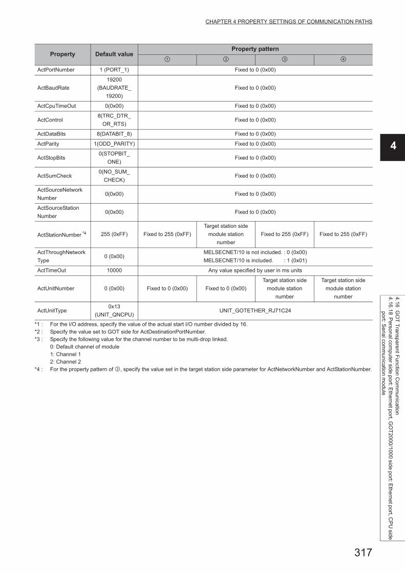
317
CHAPTER 4 PROPERTY SETTINGS OF COMMUNICATION PATHS
4
4.16 GO
T T
ransparent F
unction Com
munication
4.16.18 P
ersonal com
puter side port: Ethe
rnet port, GO
T2
000/1000 side port: E
thernet port, CP
U side
port: S
erial comm
unication m
odule
*1 : For the I/O address, specify the value of the actual start I/O number divided by 16.*2 : Specify the value set to GOT side for ActDestinationPortNumber.*3 : Specify the following value for the channel number to be multi-drop linked.
0: Default channel of module1: Channel 12: Channel 2
*4 : For the property pattern of , specify the value set in the target station side parameter for ActNetworkNumber and ActStationNumber.
ActPortNumber 1 (PORT_1) Fixed to 0 (0x00)
ActBaudRate
19200
(BAUDRATE_
19200)
Fixed to 0 (0x00)
ActCpuTimeOut 0(0x00) Fixed to 0 (0x00)
ActControl8(TRC_DTR_
OR_RTS)Fixed to 0 (0x00)
ActDataBits 8(DATABIT_8) Fixed to 0 (0x00)
ActParity 1(ODD_PARITY) Fixed to 0 (0x00)
ActStopBits0(STOPBIT_
ONE)Fixed to 0 (0x00)
ActSumCheck0(NO_SUM_
CHECK)Fixed to 0 (0x00)
ActSourceNetwork
Number0(0x00) Fixed to 0 (0x00)
ActSourceStation
Number0(0x00) Fixed to 0 (0x00)
ActStationNumber *4 255 (0xFF) Fixed to 255 (0xFF)
Target station side
module station
number
Fixed to 255 (0xFF) Fixed to 255 (0xFF)
ActThroughNetwork
Type0 (0x00)
MELSECNET/10 is not included. : 0 (0x00)
MELSECNET/10 is included. : 1 (0x01)
ActTimeOut 10000 Any value specified by user in ms units
ActUnitNumber 0 (0x00) Fixed to 0 (0x00) Fixed to 0 (0x00)
Target station side
module station
number
Target station side
module station
number
ActUnitType0x13
(UNIT_QNCPU)UNIT_GOTETHER_RJ71C24
Property Default valueProperty pattern

318
(2) When the connected station is Q series-compatible C24
(a) Configuration
(b) Property patterns
*1 : Redundant CPU cannot be accessed.*2 : Since CC-Link IE Field Network is not supported, Q12DCCPU-V (Basic mode) relayed by CC-Link IE Field Network cannot be
accessed.*3 : Since CC-Link IE Controller Network is not supported, LCPU relayed by CC-Link IE Controller Network cannot be accessed.
Connected station CPURelayed
network
Relayed station CPU
QCPU
(Q mode)
C Controller
moduleRCPU
R motion
CPU
*1
CC IE Control
CC IE Field
MELSECNET/H
Ethernet
Serial
communication
CC-Link
Connected station CPU
Relayed
network
Relayed station CPU
QCPU
(Q mode)
C Controller
module
QCPU
(Q mode)*1
C
Controller
module
LCPUQS
CPU
Q motion
CPU
FX
CPU
*1
CC IE Control
CC IE Field *2 *3
MELSECNET/H
Ethernet
Serial
communication
CC-Link
: Accessible (The number in the circle is the property pattern number.), : Inaccessible
Personal computer
Connected
station CPURelayed
module
Relayed network
Relayed
station CPU
Relayed
module
GOTSerial
Ethernet
Q series-
compatible C24

319
CHAPTER 4 PROPERTY SETTINGS OF COMMUNICATION PATHS
4
4.16 GO
T T
ransparent F
unction Com
munication
4.16.18 P
ersonal com
puter side port: Ethe
rnet port, GO
T2
000/1000 side port: E
thernet port, CP
U side
port: S
erial comm
unication m
odule
(c) Property list
The following table shows the property settings of communication paths. The setting is not necessary for those
properties without description.
Property Default valueProperty pattern
ActCpuType34
(CPU_Q02CPU)CPU type corresponding to target station
ActDestination
IONumber0 (0x00) Fixed to 0 (0x00) Fixed to 0 (0x00)
Target station side
For single CPU
Fixed to
1023 (0x3FF)
For multiple CPUs
Connected CPU:
1023 (0x3FF)
No.1: 992 (0x3E0)
No.2: 993 (0x3E1)
No.3: 994 (0x3E2)
No.4: 995 (0x3E3)
Target station side
For single CPU
Fixed to
1023 (0x3FF)
For multiple CPUs
Connected CPU:
1023 (0x3FF)
No.1: 992 (0x3E0)
No.2: 993 (0x3E1)
No.3: 994 (0x3E2)
No.4: 995 (0x3E3)
ActDestination
PortNumber0 (0x00) GOT port number
ActDidProperty
Bit1 (0x01) Fixed to 1 (0x01) Fixed to 1 (0x01) Fixed to 0 (0x00) Fixed to 0 (0x00)
ActDsidProperty
Bit1 (0x01) Fixed to 1 (0x01) Fixed to 1 (0x01) Fixed to 0 (0x00) Fixed to 0 (0x00)
ActHostAddress 1.1.1.1 Host name or IP address of GOT
ActIntelligent
PreferenceBit0 (0x00) Fixed to 0 (0x00) Fixed to 0 (0x00)
Target station
QCPU (Q mode),
C Controller module,
LCPU : 1 (0x01)
Other than the above
: 0 (0x00)
Target station
QCPU (Q mode),
C Controller module,
LCPU : 1 (0x01)
Other than the above
: 0 (0x00)
ActIONumber*1 1023 (0x3FF)
For single CPU
Fixed to
1023 (0x3FF)
For multiple CPUs
Connected CPU:
1023 (0x3FF)
No.1: 992 (0x3E0)
No.2: 993 (0x3E1)
No.3: 994 (0x3E2)
No.4: 995 (0x3E3)
Target station side
For single CPU
Fixed to
1023 (0x3FF)
For multiple CPUs
Connected CPU:
1023 (0x3FF)
No.1: 992 (0x3E0)
No.2: 993 (0x3E1)
No.3: 994 (0x3E2)
No.4: 995 (0x3E3)
Connected station
side module I/O
address
Connected station
side module I/O
address
ActMultiDrop
ChannelNumber*20 (0x00) Fixed to 0 (0x00) Fixed to 0 (0x00)
Multi-drop channel
numberFixed to 0 (0x00)
ActNetwork
Number0 (0x00) Fixed to 0 (0x00)
Target station side
module network
number
Fixed to 0 (0x00) Fixed to 0 (0x00)
ActProtocolType
0x04
(PROTOCOL_
SERIAL)
PROTOCOL_TCPIP (0x05)
ActStation
Number255 (0xFF) Fixed to 255 (0xFF)
Target station side
module station
number
Fixed to 255 (0xFF) Fixed to 255 (0xFF)

320
*1 : For the I/O address, specify the value of the actual start I/O number divided by 16.*2 : Specify the following value for the channel number to be multi-drop linked.
0: Default channel of module1: Channel 12: Channel 2
ActThrough
NetworkType0 (0x00)
MELSECNET/10 is not included. : 0 (0x00)
MELSECNET/10 is included. : 1 (0x01)
ActTimeOut 10000 Any value specified by user in ms units
ActUnitNumber 0 (0x00) Fixed to 0 (0x00) Fixed to 0 (0x00)
Target station side
module station
number
Target station side
module station
number
ActUnitType0x13
(UNIT_QNCPU)UNIT_GOTETHER_QNCPU (0x56)
Property Default valueProperty pattern
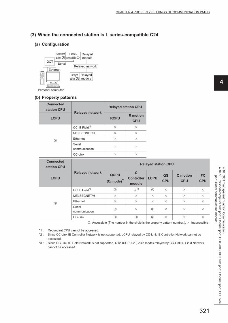
321
CHAPTER 4 PROPERTY SETTINGS OF COMMUNICATION PATHS
4
4.16 GO
T T
ransparent F
unction Com
munication
4.16.18 P
ersonal com
puter side port: Ethe
rnet port, GO
T2
000/1000 side port: E
thernet port, CP
U side
port: S
erial comm
unication m
odule
(3) When the connected station is L series-compatible C24
(a) Configuration
(b) Property patterns
*1 : Redundant CPU cannot be accessed.*2 : Since CC-Link IE Controller Network is not supported, LCPU relayed by CC-Link IE Controller Network cannot be
accessed.*3 : Since CC-Link IE Field Network is not supported, Q12DCCPU-V (Basic mode) relayed by CC-Link IE Field Network
cannot be accessed.
Connected
station CPURelayed network
Relayed station CPU
LCPU RCPUR motion
CPU
CC IE Field*2
MELSECNET/H
Ethernet
Serial
communication
CC-Link
Connected
station CPU
Relayed network
Relayed station CPU
LCPUQCPU
(Q mode)*1
C
Controller
module
LCPUQS
CPU
Q motion
CPU
FX
CPU
CC IE Field*2 *3
MELSECNET/H
Ethernet
Serial
communication
CC-Link
: Accessible (The number in the circle is the property pattern number.), : Inaccessible
Personal computer
Connected
station CPURelayed
module
Relayed network
Relayed
station CPU
Relayed
module
GOTSerial
Ethernet
L series-
compatible C24

322
(c) Property list
The following table shows the property settings of communication paths. The setting is not necessary for those
properties without description.
Property Default valueProperty pattern
ActCpuType34
(CPU_Q02CPU)CPU type corresponding to target station
ActDestinationIO
Number0 (0x00) Fixed to 0 (0x00)
Target station side
For single CPU
Fixed to
1023 (0x3FF)
For multiple CPUs
Connected CPU:
1023 (0x3FF)
No.1: 992 (0x3E0)
No.2: 993 (0x3E1)
No.3: 994 (0x3E2)
No.4: 995 (0x3E3)
Target station side
For single CPU
Fixed to
1023 (0x3FF)
For multiple CPUs
Connected CPU:
1023 (0x3FF)
No.1: 992 (0x3E0)
No.2: 993 (0x3E1)
No.3: 994 (0x3E2)
No.4: 995 (0x3E3)
Fixed to 0 (0x00)
ActDestinationPort
Number0 (0x00) GOT port number
ActDidPropertyBit 1 (0x01) Fixed to 1 (0x01) Fixed to 0 (0x00) Fixed to 0 (0x00) Fixed to 1 (0x01)
ActDsidPropertyBit 1 (0x01) Fixed to 1 (0x01) Fixed to 0 (0x00) Fixed to 0 (0x00) Fixed to 1 (0x01)
ActHostAddress 1.1.1.1 Host name or IP address of GOT
ActIntelligent
PreferenceBit0 (0x00) Fixed to 0 (0x00)
Target station
QCPU (Q mode),
C Controller module,
LCPU : 1 (0x01)
Other than the above
: 0 (0x00)
Target station
QCPU (Q mode),
C Controller module,
LCPU : 1 (0x01)
Other than the above
: 0 (0x00)
Fixed to 0 (0x00)
ActIONumber*1 1023 (0x3FF)Fixed to 1023
(0x3FF)
Connected station side
module I/O address
Connected station side
module I/O address
Target station side
For single CPU
Fixed to
1023 (0x3FF)
For multiple CPUs
Connected CPU:
1023 (0x3FF)
No.1: 992 (0x3E0)
No.2: 993 (0x3E1)
No.3: 994 (0x3E2)
No.4: 995 (0x3E3)
ActMultiDrop
ChannelNumber*20 (0x00) Fixed to 0 (0x00)
Multi-drop channel
numberFixed to 0 (0x00) Fixed to 0 (0x00)
ActNetworkNumber 0 (0x00) Fixed to 0 (0x00) Fixed to 0 (0x00) Fixed to 0 (0x00)
Target station side
module network
number
ActProtocolType
0x04
(PROTOCOL_
SERIAL)
PROTOCOL_TCPIP (0x05)
ActStationNumber 255 (0xFF)Fixed to 255
(0xFF)Fixed to 255 (0xFF) Fixed to 255 (0xFF)
Target station side
module station number
ActThrough
NetworkType0 (0x00)
MELSECNET/10 is not included. : 0 (0x00)
MELSECNET/10 is included. : 1 (0x01)
ActTimeOut 10000 Any value specified by user in ms units
ActUnitNumber 0 (0x00) Fixed to 0 (0x00)Target station side
module station number
Target station side
module station numberFixed to 0 (0x00)
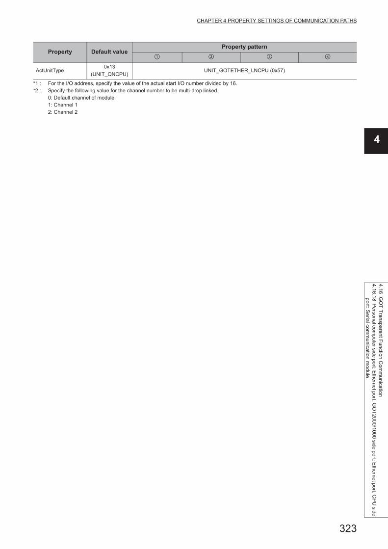
323
CHAPTER 4 PROPERTY SETTINGS OF COMMUNICATION PATHS
4
4.16 GO
T T
ransparent F
unction Com
munication
4.16.18 P
ersonal com
puter side port: Ethe
rnet port, GO
T2
000/1000 side port: E
thernet port, CP
U side
port: S
erial comm
unication m
odule
*1 : For the I/O address, specify the value of the actual start I/O number divided by 16.*2 : Specify the following value for the channel number to be multi-drop linked.
0: Default channel of module1: Channel 12: Channel 2
ActUnitType0x13
(UNIT_QNCPU)UNIT_GOTETHER_LNCPU (0x57)
Property Default valueProperty pattern

324
4.16.19 Personal computer side port: Ethernet port, GOT2000/1000 side port: Ethernet port, CPU side port: Bus connection
(1) Configuration
(2) Property patterns
Connected station CPU
Relayed network
Relayed station CPU
QCPU (Q mode) RCPUR motion
CPU
*1
CC IE Control
CC IE Field
MELSECNET/H
Ethernet
Serial
communication
CC-Link
Connected station CPU
Relayed network
Relayed station CPU
QCPU (Q mode)QCPU
(Q mode)*1
C
Controller
module
LCPUQS
CPU
Q motion
CPU
FX
CPU
*1
CC IE Control
CC IE Field *2 *3
MELSECNET/H
Ethernet
Serial
communication
CC-Link
Personal computer
Connected
station CPU
Relayed
module
Relayed network
Relayed
station CPU
Relayed
module
GOT
Ethernet
Bus

325
CHAPTER 4 PROPERTY SETTINGS OF COMMUNICATION PATHS
4
4.16 GO
T T
ransparent F
unction Com
munication
4.16.19 P
ersonal com
puter side port: Ethe
rnet port, GO
T2
000/1000 side port: E
thernet port, CP
U side
port: B
us connection
*1 : Redundant CPU cannot be accessed.*2 : Since CC-Link IE Field Network is not supported, Q12DCCPU-V (Basic mode) relayed by CC-Link IE Field Network cannot be
accessed.*3 : Since CC-Link IE Controller Network is not supported, LCPU relayed by CC-Link IE Controller Network cannot be accessed.
Connected station CPU
Relayed network
Relayed station CPU
C Controller module RCPUR motion
CPU
CC IE Control
CC IE Field
MELSECNET/H
Ethernet
Serial
communication
CC-Link
Connected station CPU
Relayed network
Relayed station CPU
C Controller moduleQCPU
(Q mode)*1
C
Controller
module
LCPUQS
CPU
Q motion
CPU
FX
CPU
CC IE Control
CC IE Field *2 *3
MELSECNET/H
Ethernet
Serial
communication
CC-Link
: Accessible (The number in the circle is the property pattern number.), : Inaccessible
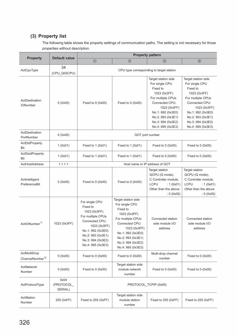
326
(3) Property listThe following table shows the property settings of communication paths. The setting is not necessary for those
properties without description.
Property Default valueProperty pattern
ActCpuType34
(CPU_Q02CPU)CPU type corresponding to target station
ActDestination
IONumber0 (0x00) Fixed to 0 (0x00) Fixed to 0 (0x00)
Target station side
For single CPU
Fixed to
1023 (0x3FF)
For multiple CPUs
Connected CPU:
1023 (0x3FF)
No.1: 992 (0x3E0)
No.2: 993 (0x3E1)
No.3: 994 (0x3E2)
No.4: 995 (0x3E3)
Target station side
For single CPU
Fixed to
1023 (0x3FF)
For multiple CPUs
Connected CPU:
1023 (0x3FF)
No.1: 992 (0x3E0)
No.2: 993 (0x3E1)
No.3: 994 (0x3E2)
No.4: 995 (0x3E3)
ActDestination
PortNumber0 (0x00) GOT port number
ActDidProperty
Bit1 (0x01) Fixed to 1 (0x01) Fixed to 1 (0x01) Fixed to 0 (0x00) Fixed to 0 (0x00)
ActDsidProperty
Bit1 (0x01) Fixed to 1 (0x01) Fixed to 1 (0x01) Fixed to 0 (0x00) Fixed to 0 (0x00)
ActHostAddress 1.1.1.1 Host name or IP address of GOT
ActIntelligent
PreferenceBit0 (0x00) Fixed to 0 (0x00) Fixed to 0 (0x00)
Target station
QCPU (Q mode),
C Controller module,
LCPU : 1 (0x01)
Other than the above
: 0 (0x00)
Target station
QCPU (Q mode),
C Controller module,
LCPU : 1 (0x01)
Other than the above
: 0 (0x00)
ActIONumber*1 1023 (0x3FF)
For single CPU
Fixed to
1023 (0x3FF)
For multiple CPUs
Connected CPU:
1023 (0x3FF)
No.1: 992 (0x3E0)
No.2: 993 (0x3E1)
No.3: 994 (0x3E2)
No.4: 995 (0x3E3)
Target station side
For single CPU
Fixed to
1023 (0x3FF)
For multiple CPUs
Connected CPU:
1023 (0x3FF)
No.1: 992 (0x3E0)
No.2: 993 (0x3E1)
No.3: 994 (0x3E2)
No.4: 995 (0x3E3)
Connected station
side module I/O
address
Connected station
side module I/O
address
ActMultiDrop
ChannelNumber*20 (0x00) Fixed to 0 (0x00) Fixed to 0 (0x00)
Multi-drop channel
numberFixed to 0 (0x00)
ActNetwork
Number0 (0x00) Fixed to 0 (0x00)
Target station side
module network
number
Fixed to 0 (0x00) Fixed to 0 (0x00)
ActProtocolType
0x04
(PROTOCOL_
SERIAL)
PROTOCOL_TCPIP (0x05)
ActStation
Number255 (0xFF) Fixed to 255 (0xFF)
Target station side
module station
number
Fixed to 255 (0xFF) Fixed to 255 (0xFF)

327
CHAPTER 4 PROPERTY SETTINGS OF COMMUNICATION PATHS
4
4.16 GO
T T
ransparent F
unction Com
munication
4.16.19 P
ersonal com
puter side port: Ethe
rnet port, GO
T2
000/1000 side port: E
thernet port, CP
U side
port: B
us connection
*1 : For the I/O address, specify the value of the actual start I/O number divided by 16.*2 : Specify the following value for the channel number to be multi-drop linked.
0: Default channel of module1: Channel 12: Channel 2
ActThrough
NetworkType0 (0x00)
MELSECNET/10 is not included. : 0 (0x00)
MELSECNET/10 is included. : 1 (0x01)
ActTimeOut 10000 Any value specified by user in ms units
ActUnitNumber 0 (0x00) Fixed to 0 (0x00) Fixed to 0 (0x00)
Target station side
module station
number
Target station side
module station
number
ActUnitType0x13
(UNIT_QNCPU)UNIT_GOTETHER_QBUS (0x58)
Property Default valueProperty pattern

328
4.17 Q Series Bus Communication
(1) Configuration
(2) Property patterns
(3) Property listThe following table shows the property settings of communication paths. The setting is not necessary for those
properties without description.
Own Base
RCPU R motion CPU
Own Base
QCPU (Q mode) C Controller module Q motion CPU
: Accessible (The number in the circle is the property pattern number.), : Inaccessible
Property Default valueProperty pattern
ActCpuType 34 (CPU_Q02CPU) CPU type corresponding to the target station
ActIONumber*1 1023 (0x3FF)
No.1 992 (0x3E0)
No.2 993 (0x3E1)
No.3 994 (0x3E2)
ActProtocolType0x04
(PROTOCOL_SERIAL)PROTOCOL_QBF (0x10)
ActUnitType 0x13 (UNIT_QNCPU) UNIT_QBF (0x1F)
PC CPU moduleNo. 3No. 1 No. 2

329
CHAPTER 5 FUNCTIONS
5
CHAPTER 5 FUNCTIONS
This chapter explains the considerations of programming and details of functions.
Read the considerations of programming described in Section 5.1 before creating a program.
(1) Types of functionsFunctions for .NET control and functions for ACT control are the types of functions. An applicable interface and
programming language are different according to the function.
(2) Interface typesDispatch interface and custom interface can be used for the functions for ACT control.
Control Interface Programming language Reference
ACT control
Dispatch interface
(Recommended)
VBA
Visual C++® .NET (MFC)
VBScript
Visual Basic® .NET
Visual C++® .NET
Visual C#® .NET
Page 333, Section 5.2
Custom interface Visual C++® .NET (MFC)
.NET control Dispatch interface
Visual Basic® .NET
Visual C++® .NET
Visual C#® .NET
Page 420, Section 5.3
Interface Description Characteristic
Dispatch
interface
Paste controls on the form of Visual Basic®
.NET, Visual C++® .NET, Visual C#® .NET, or
VBA (Excel, Access) to use the controls.
Programming to acquire the interface and to create
objects is not necessary. (Programs to create objects
without pasting controls on the form can be created.)
Programming with dispatch interface is easier than
programming with custom interface
Custom interface
Acquire the interface using the interface
acquisition function when using controls.
Use the object creation function to create
objects.
Programs of custom interface are complicated as
compared to those of dispatch interface, however the
object creation/extinction can be managed in detail.

330
5.1 Programming Considerations
This section explains the considerations of programming.
(1) Considerations of multi-thread programmingWhen performing multi-thread programming, follow the rules of COM and ActiveX controls.
For details, refer to the rules and reference books of COM and ActiveX controls.
● The ActiveX controls used on MX Component are those of the STA model.
● When passing the interface pointer to another apartment, the interface pointer needs to be marshaled.Synchronize programs using CoMarshalInterThreadInterfaceInStream or CoGetInterfaceAndReleaseStream of the COM function.
(2) Open function (opening communication line)The processing may take long time due to the Open function processes: establishment of communication paths,
obtaining programmable controller internal information, or the like.
A user needs to create efficient programs in order to improve the speed performance of user applications.
The following figures are flows for creating efficient and inefficient user programs.
Start
Close the user application?
Open the communication line. (Open)
Close the communication line. (Close)
Complete
Access the programmable controller CPU or module
using the function (such as GetDevice).
No
Yes
<Efficient user application>
Start
Close the user application?
Open the communication line. (Open)
Close the communication line. (Close)
Complete
Access the programmable controller CPU or module
using the function (such as GetDevice).
No
Yes
<Inefficient user application>

331
CHAPTER 5 FUNCTIONS
5
5.1 Program
ming C
onsiderations
(3) Considerations for using QSCPUThe following functions cannot be used for QSCPU.
If any of these functions is used, the error code "0x010A42A0" (mismatched CPU access password) will be returned.
(4) Considerations for using inverter/robot controllerThe function of .NET control cannot be used during performing inverter communication/robot controller
communication.
If any of these functions is used, the error code "0xF0000007" (function non-support error) will be returned.
Function Name Description
WriteDeviceBlock Write devices in bulk.
WriteDeviceRandom Write devices randomly.
SetDevice Set device data.
WriteBuffer Write data to buffer memory.
SetClockData Write clock data.
SetCpuStatus Remote control
WriteDeviceBlock2 Write devices in bulk.
WriteDeviceRandom2 Write devices randomly.
SetDevice2 Set device data.
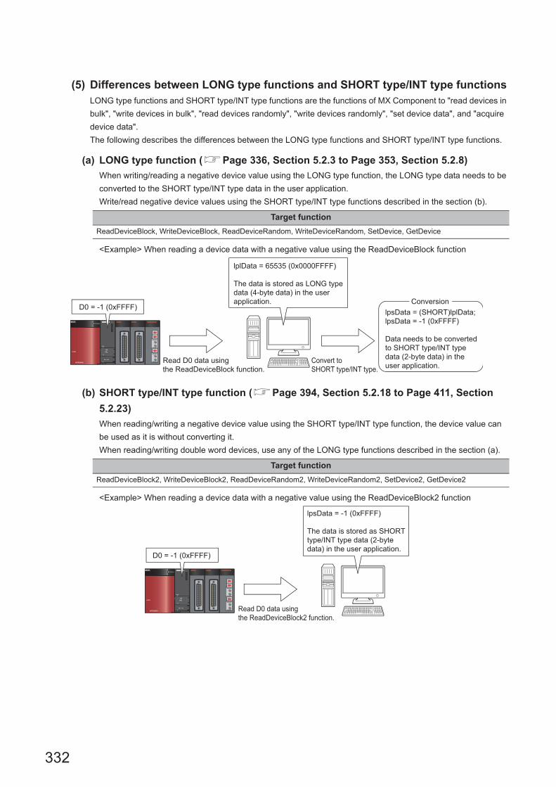
332
(5) Differences between LONG type functions and SHORT type/INT type functionsLONG type functions and SHORT type/INT type functions are the functions of MX Component to "read devices in
bulk", "write devices in bulk", "read devices randomly", "write devices randomly", "set device data", and "acquire
device data".
The following describes the differences between the LONG type functions and SHORT type/INT type functions.
(a) LONG type function (Page 336, Section 5.2.3 to Page 353, Section 5.2.8)
When writing/reading a negative device value using the LONG type function, the LONG type data needs to be
converted to the SHORT type/INT type data in the user application.
Write/read negative device values using the SHORT type/INT type functions described in the section (b).
<Example> When reading a device data with a negative value using the ReadDeviceBlock function
(b) SHORT type/INT type function (Page 394, Section 5.2.18 to Page 411, Section
5.2.23)
When reading/writing a negative device value using the SHORT type/INT type function, the device value can
be used as it is without converting it.
When reading/writing double word devices, use any of the LONG type functions described in the section (a).
<Example> When reading a device data with a negative value using the ReadDeviceBlock2 function
Target function
ReadDeviceBlock, WriteDeviceBlock, ReadDeviceRandom, WriteDeviceRandom, SetDevice, GetDevice
Target function
ReadDeviceBlock2, WriteDeviceBlock2, ReadDeviceRandom2, WriteDeviceRandom2, SetDevice2, GetDevice2
Read D0 data using
the ReadDeviceBlock function.
Convert to
SHORT type/INT type.
D0 = -1 (0xFFFF)
lplData = 65535 (0x0000FFFF)
The data is stored as LONG type
data (4-byte data) in the user
application.
lpsData = (SHORT)lplData;
lpsData = -1 (0xFFFF)
Data needs to be converted
to SHORT type/INT type
data (2-byte data) in the
user application.
Conversion
Read D0 data using
the ReadDeviceBlock2 function.
D0 = -1 (0xFFFF)
lpsData = -1 (0xFFFF)
The data is stored as SHORT
type/INT type data (2-byte
data) in the user application.

333
CHAPTER 5 FUNCTIONS
5
5.2 Details of F
unctions (For A
CT
Control)
5.2.1 Open (O
pening com
mun
ication line)
5.2 Details of Functions (For ACT Control)
5.2.1 Open (Opening communication line)
(1) Applicable controlsApplicable to the Act(ML)ProgType control and the Act(ML)UtlType control.
(2) FeatureOpen the communication line.
(3) Format (Dispatch interface)
(a) Visual C++® .NET (MFC), VBA
lRet = object.Open()
(b) VBScript
varRet = object.Open()
(c) Visual Basic® .NET
IRet = object.Open()
(d) Visual C++® .NET
iRet = object.Open()
(e) Visual C#® .NET
iRet = object.Open()
(4) Format (Custom interface)
(a) Visual C++® .NET (MFC)
hResult = object.Open( *lplRetCode )
(5) DescriptionLines are connected according to the set value of the Open function property.
Long lRet Returned value Output
VARIANT varRet Returned value (LONG type) Output
Integer IRet Returned value Output
int iRet Returned value Output
int iRet Returned value Output
HRESULT hResult Returned value of COM Output
LONG *lplRetCodeReturned value of communication
functionOutput

334
(6) Returned valueNormal termination : 0 is returned.
Abnormal termination: Any value other than 0 is returned. (Page 516, CHAPTER 7 ERROR CODES)
● When modem communication is used, the Open function cannot be executed without the execution of the Connect function.
● If the Open function property is changed after the completion of the Open function, the setting of communication target is not changed. To change the communication setting, close the communication line, set the setting of communication target, and open the communication line again.
● Even when a CPU type which is different from the CPU used for the communication is set to the ActCpuType property, the Open function may be completed normally.In such a case, the connection range, usable method, or device range may be narrowed.When executing the Open function, set the correct CPU type to the ActCpuType property.

335
CHAPTER 5 FUNCTIONS
5
5.2 Details of F
unctions (For A
CT
Control)
5.2.2 Close (C
losing comm
unication line)
5.2.2 Close (Closing communication line)
(1) Applicable controlsApplicable to the Act(ML)ProgType control and the Act(ML)UtlType control.
(2) FeatureClose the communication line.
(3) Format (Dispatch interface)
(a) Visual C++® .NET (MFC), VBA
lRet = object.Close()
(b) VBScript
varRet = object.Close()
(c) Visual Basic® .NET
IRet = object.Close()
(d) Visual C++® .NET
iRet = object.Close()
(e) Visual C#® .NET
iRet = object.Close()
(4) Format (Custom interface)
(a) Visual C++® .NET (MFC)
hResult = object.Close( *lplRetCode )
(5) DescriptionThe line connected using the Open function is closed.
(6) Returned valueNormal termination : 0 is returned.
Abnormal termination: Any value other than 0 is returned. (Page 516, CHAPTER 7 ERROR CODES)
Long lRet Returned value Output
VARIANT varRet Returned value (LONG type) Output
Integer IRet Returned value Output
int iRet Returned value Output
int iRet Returned value Output
HRESULT hResult Returned value of COM Output
LONG *lplRetCodeReturned value of communication
functionOutput

336
5.2.3 ReadDeviceBlock (Reading devices in bulk)
(1) Applicable controls
Applicable to the Act(ML)ProgType control and the Act(ML)UtlType control.*1
*1 : Not applicable to inverter communication/robot controller communication.
(2) FeatureRead devices in bulk.
(3) Format (Dispatch interface)
(a) VBA
lRet = object.ReadDeviceBlock(szDevice, lSize, lData(0))
(b) Visual C++® .NET (MFC)
lRet = object.ReadDeviceBlock(szDevice, lSize, *lplData)
(c) VBScript
varRet = object.ReadDeviceBlock(varDevice, varSize, lpvarData)
(d) Visual Basic® .NET
IRet = object.ReadDeviceBlock(szDevice, iSize, iData(0))
(e) Visual C++® .NET
iRet = object.ReadDeviceBlock(*szDevice, iSize, *iplData)
Long lRet Returned value Output
String szDevice Device name Input
Long lSize Number of read points Input
Long lData(n) Read device value Output
Long lRet Returned value Output
CString szDevice Device name Input
Long lSize Number of read points Input
Long *lplData Read device value Output
VARIANT varRet Returned value (LONG type) Output
VARIANT varDevice Device name (character string type) Input
VARIANT varSize Number of read points (LONG type) Input
VARIANT lpvarData Read device value (LONG array type) Output
Integer IRet Returned value Output
String szDevice Device name Input
Integer iSize Number of read points Input
Integer iData(n) Read device value Output
int iRet Returned value Output
String *szDevice Device name Input
int iSize Number of read points Input
int *iplData Read device value Output

337
CHAPTER 5 FUNCTIONS
5
5.2 Details of F
unctions (For A
CT
Control)
5.2.3 ReadD
eviceBlock (R
eading devices in bulk)
(f) Visual C#® .NET
iRet = object.ReadDeviceBlock(szDevice, iSize, out iData(0))
(4) Format (Custom interface)
(a) Visual C++® .NET (MFC)
hResult = object.ReadDeviceBlock( szDevice, lSize, *lplData, *lplRetCode )
(5) Description • The device values for the amount specified for lSize (varSize) are read in bulk starting from the device
specified for szDevice (varDevice).
• The read device values are stored in lData (lplData or lpvarData).
• For lData (lplData or lpvarData), reserve arrays for more than the amount specified for lSize (varSize).
int iRet Returned value Output
String szDevice Device name Input
int iSize Number of read points Input
int(n) iData Read device value Output
HRESULT hResult Returned value of COM Output
BSTR szDevice Device name Input
LONG lSize Number of read points Input
LONG *lplData Read device value Output
LONG *lplRetCode Returned value of communication function Output

338
(6) How to specify devicesThe following describes how to specify devices.
<When bit device is specified> <When word device is specified>
Example: Read 3 points (3 words) of data in 16-point unit
starting from M0.Example: Read 3 points of data starting from D0.
<When double-word device is specified> <When FXCPU devices of CN200 and later are specified>
Example: Read 3 points from LTN0 Example: Read 6 points of data starting from CN200.*2
<When FD device is specified (4-word device)>
Example: Read 6 points of data starting from FD0.
<8-bit devices assigned to gateway devices>
Example: Read 4 points of data starting from EG0.
(When 8-bit devices (from E0000 to E0007 of SHARP programmable controller) are assigned from EG0 to EG3.)
*1 : Devices are stored from the lower bit in the order of device number.*2 : For CN200 or later of FXCPU, 2 words are read for each 2 points. Reading only 1 point of data will result in an error.
Upper 2 bytes Lower 2 bytes
Not used
(0 is stored.)
M0 to M15*1
M16 to M31*1
M32 to M47*1
Upper 2 bytes Lower 2 bytes
Not used
(0 is stored.)
D0
D1
D2
Upper 2 bytes Lower 2 bytes
H of LTN0 L of LTN0
H of LTN1 L of LTN1
H of LTN2 L of LTN2
Upper 2 bytes Lower 2 bytes
Not used
(0 is stored.)
L of CN200
H of CN200
L of CN201
H of CN201
L of CN202
H of CN202
Upper 2 bytes Lower 2 bytes
Not used
(0 is stored.)
LL of FD0
LH of FD0
HL of FD0
HH of FD0
LL of FD1
LH of FD1
Upper 2 bytes Lower 2 bytes
Not used
(0 is stored.)
EG0
(E0001) (E0000)
EG1
(E0003) (E0002)
EG2
(E0005) (E0004)
EG3
(E0007) (E0006)

339
CHAPTER 5 FUNCTIONS
5
5.2 Details of F
unctions (For A
CT
Control)
5.2.3 ReadD
eviceBlock (R
eading devices in bulk)
(7) Returned valueNormal termination : 0 is returned.
Abnormal termination: Any value other than 0 is returned. (Page 516, CHAPTER 7 ERROR CODES)
● The maximum number of read points that can be specified for lSize (varSize) should be the value which satisfies the following condition.Read start device number + Number of read points Last device number
● When specifying bit devices, a multiple of 16 can be specified as a device number.
● For lData (lplData or lpvarData), reserve a memory area for the number of points specified for lSize (varSize).If the memory area is not reserved, a critical error (an application error or the like) may occur.

340
5.2.4 WriteDeviceBlock (Writing devices in bulk)
(1) Applicable controls
Applicable to the Act(ML)ProgType control and the Act(ML)UtlType control.*1
*1 : Not applicable to inverter communication/robot controller communication.
(2) FeatureWrite devices in bulk.
(3) Format (Dispatch interface)
(a) VBA
lRet = object.WriteDeviceBlock(szDevice, lSize, lData(0))
(b) Visual C++® .NET (MFC)
lRet = object.WriteDeviceBlock(szDevice, lSize, *lplData)
(c) VBScript
varRet = object.WriteDeviceBlock(varDevice, varSize, varData)
(d) Visual Basic® .NET
IRet = object.WriteDeviceBlock(szDevice, iSize, iData(0))
(e) Visual C++® .NET
iRet = object.WriteDeviceBlock(*szDevice, iSize, *iplData)
Long lRet Returned value Output
String szDevice Device name Input
Long lSize Number of write points Input
Long lData(n) Device value to be written Input
Long lRet Returned value Output
CString szDevice Device name Input
Long lSize Number of write points Input
Long *lplData Device value to be written Input
VARIANT varRet Returned value (LONG type) Output
VARIANT varDevice Device name (character string type) Input
VARIANT varSize Number of write points (LONG type) Input
VARIANT varData Device value to be written (LONG array type) Input
Integer IRet Returned value Output
String szDevice Device name Input
Integer iSize Number of write points Input
Integer iData(n) Device value to be written Input
int iRet Returned value Output
String *szDevice Device name Input
int iSize Number of write points Input
int *iplData Device value to be written Input

341
CHAPTER 5 FUNCTIONS
5
5.2 Details of F
unctions (For A
CT
Control)
5.2.4 WriteD
eviceBlock (W
riting devices in bulk)
(f) Visual C#® .NET
iRet = object.WriteDeviceBlock(szDevice, iSize, ref iData(0))
(4) Format (Custom interface)
(a) Visual C++® .NET (MFC)
hResult = object.WriteDeviceBlock( szDevice, lSize, *lplData, *lplRetCode )
(5) Description • The device values of lSize (varSize) are written in bulk starting from the device specified for szDevice
(varDevice).
• The device values to be written are stored in lData (lplData or varData).
• For lData (lplData or varData), reserve arrays for more than the amount specified for lSize (varSize).
(6) How to specify devicesThe following describes how to specify devices.
int iRet Returned value Output
String szDevice Device name Input
int iSize Number of write points Input
int(n) iData Device value to be written Input
HRESULT hResult Returned value of COM Output
BSTR szDevice Device name Input
LONG lSize Number of write points Input
LONG *lplData Device value to be written Input
LONG *lplRetCode Returned value of communication function Output
<When bit device is specified> <When word device is specified>
Example: Write 3 points (3 words) of data in 16-point unit
starting from M0.Example: Write 3 points of data starting from D0.
<When double-word device is specified> <When FXCPU devices of CN200 and later are specified>
Example: Write 3 points to LTN0 Example: Write 6 points of data starting from CN200.*2
*1 : Devices are stored from the lower bit in the order of device number.*2 : For CN200 or later of FXCPU, 2 words are written for each 2 points. Writing only 1 point of data will result in an error.
Upper 2 bytes Lower 2 bytes
Not used
(0 is stored.)
M0 to M15*1
M16 to M31*1
M32 to M47*1
Upper 2 bytes Lower 2 bytes
Not used
(0 is stored.)
D0
D1
D2
Upper 2 bytes Lower 2 bytes
H of LTN0 L of LTN0
H of LTN1 L of LTN1
H of LTN2 L of LTN2
Upper 2 bytes Lower 2 bytes
Not used
(0 is stored.)
L of CN200
H of CN200
L of CN201
H of CN201
L of CN202
H of CN202

342
(7) Returned valueNormal termination : 0 is returned.
Abnormal termination: Any value other than 0 is returned. (Page 516, CHAPTER 7 ERROR CODES)
● The maximum number of write points that can be specified for lSize(varSize) should be the value which satisfies the following condition.Write starting device number + Number of write points Last device number
● When specifying bit devices, a multiple of 16 can be specified as a device number.
● For lData (lplData or varData), reserve a memory area for the number of points specified for lSize (varSize).If the memory area is not reserved, a critical error (an application error or the like) may occur.
● WriteDeviceBlock cannot be used for writing long timer device (LT) and retentive long timer device (LST).Use WriteDeviceRandom or SetDevice.
<When FD device is specified (4-word device)>
Example: Write 6 points of data starting from FD0.
<8-bit devices assigned to gateway devices>
Example: Write 4 points of data starting from EG0.
(When 8-bit devices (from E0000 to E0007 of SHARP programmable controller) are assigned from EG0 to EG3.)
Upper 2 bytes Lower 2 bytes
Not used
(0 is stored.)
LL of FD0
LH of FD0
HL of FD0
HH of FD0
LL of FD1
LH of FD1
Upper 2 bytes Lower 2 bytes
Not used
(0 is stored.)
EG0
(E0001) (E0000)
EG1
(E0003) (E0002)
EG2
(E0005) (E0004)
EG3
(E0007) (E0006)
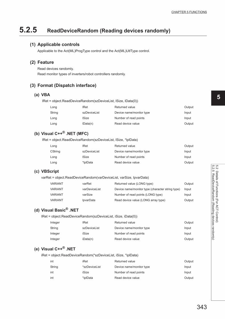
343
CHAPTER 5 FUNCTIONS
5
5.2 Details of F
unctions (For A
CT
Control)
5.2.5 ReadD
eviceRa
ndom (R
eading
devices randomly)
5.2.5 ReadDeviceRandom (Reading devices randomly)
(1) Applicable controlsApplicable to the Act(ML)ProgType control and the Act(ML)UtlType control.
(2) FeatureRead devices randomly.
Read monitor types of inverters/robot controllers randomly.
(3) Format (Dispatch interface)
(a) VBA
lRet = object.ReadDeviceRandom(szDeviceList, lSize, lData(0))
(b) Visual C++® .NET (MFC)
lRet = object.ReadDeviceRandom(szDeviceList, lSize, *lplData)
(c) VBScript
varRet = object.ReadDeviceRandom(varDeviceList, varSize, lpvarData)
(d) Visual Basic® .NET
IRet = object.ReadDeviceRandom(szDeviceList, iSize, iData(0))
(e) Visual C++® .NET
iRet = object.ReadDeviceRandom(*szDeviceList, iSize, *iplData)
Long lRet Returned value Output
String szDeviceList Device name/monitor type Input
Long lSize Number of read points Input
Long lData(n) Read device value Output
Long lRet Returned value Output
CString szDeviceList Device name/monitor type Input
Long lSize Number of read points Input
Long *lplData Read device value Output
VARIANT varRet Returned value (LONG type) Output
VARIANT varDeviceList Device name/monitor type (character string type) Input
VARIANT varSize Number of read points (LONG type) Input
VARIANT lpvarData Read device value (LONG array type) Output
Integer IRet Returned value Output
String szDeviceList Device name/monitor type Input
Integer iSize Number of read points Input
Integer iData(n) Read device value Output
int iRet Returned value Output
String *szDeviceList Device name/monitor type Input
int iSize Number of read points Input
int *iplData Read device value Output
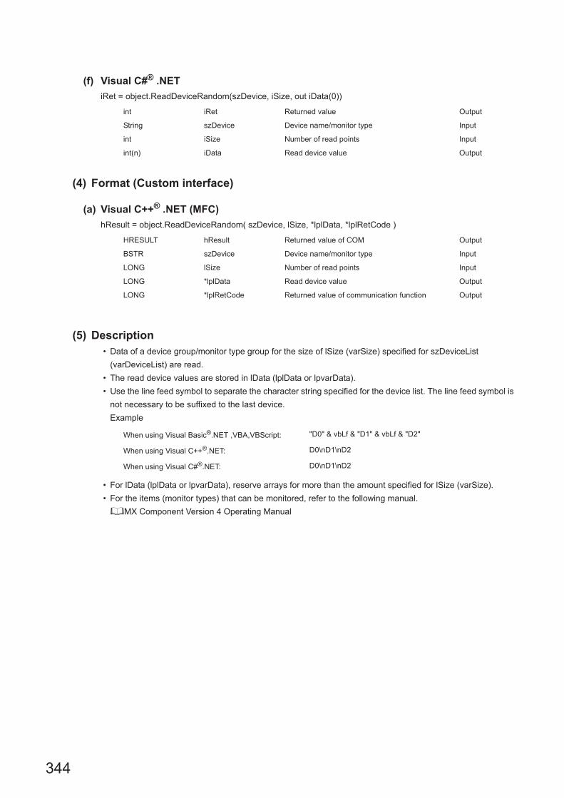
344
(f) Visual C#® .NET
iRet = object.ReadDeviceRandom(szDevice, iSize, out iData(0))
(4) Format (Custom interface)
(a) Visual C++® .NET (MFC)
hResult = object.ReadDeviceRandom( szDevice, lSize, *lplData, *lplRetCode )
(5) Description • Data of a device group/monitor type group for the size of lSize (varSize) specified for szDeviceList
(varDeviceList) are read.
• The read device values are stored in lData (lplData or lpvarData).
• Use the line feed symbol to separate the character string specified for the device list. The line feed symbol is
not necessary to be suffixed to the last device.
Example
• For lData (lplData or lpvarData), reserve arrays for more than the amount specified for lSize (varSize).
• For the items (monitor types) that can be monitored, refer to the following manual.
MX Component Version 4 Operating Manual
int iRet Returned value Output
String szDevice Device name/monitor type Input
int iSize Number of read points Input
int(n) iData Read device value Output
HRESULT hResult Returned value of COM Output
BSTR szDevice Device name/monitor type Input
LONG lSize Number of read points Input
LONG *lplData Read device value Output
LONG *lplRetCode Returned value of communication function Output
When using Visual Basic®.NET ,VBA,VBScript: "D0" & vbLf & "D1" & vbLf & "D2"
When using Visual C++®.NET: D0\nD1\nD2
When using Visual C#®.NET: D0\nD1\nD2

345
CHAPTER 5 FUNCTIONS
5
5.2 Details of F
unctions (For A
CT
Control)
5.2.5 ReadD
eviceRa
ndom (R
eading
devices randomly)
(6) How to specify devicesThe following describes how to specify devices.
Example 1: When devices are specified as follows (Number of points: 3 points)
Example 2: When double word devices are specified
Example 3: When devices including FXCPU devices of CN200 and later are specified (Total number of points: 3
points)*2
Example 4: When devices including FD are specified (Total number of points: 3 points)
*1 : Devices are stored from the lower bit in the order of device number.*2 : For CN200 or later of FXCPU, 2 words are read for each point when reading devices randomly.
When using Visual Basic®.NET ,VBA,VBScript: "M0" & vbLf & "D0" & vbLf & "K8M0"
When using Visual C++®.NET: M0\nD0\nK8M0
When using Visual C#®.NET: M0\nD0\nK8M0
Upper 2 bytes Lower 2 bytes
Not used
(0 is stored.)
M0
D0
M16 to M31*1 M0 to M15*1
When using Visual Basic®.NET ,VBA,VBScript: "LTN0" & vbLf & "LTN1" & vbLf & "LTN2"
When using Visual C++®.NET: LTN0\nLTN1\nLTN2
When using Visual C#®.NET: LTN0\nLTN1\nLTN2
Upper 2 bytes Lower 2 bytes
H of LTN0 L of LTN0
H of LTN1 L of LTN1
H of LTN2 L of LTN2
When using Visual Basic®.NET ,VBA,VBScript: "D0" & vbLf & "CN200" & vbLf & "D1"
When usingVisual C++®.NET: D0\nCN200\nD1
When using Visual C#®.NET: D0\nCN200\nD1
Upper 2 bytes Lower 2 bytes
Not used
(0 is stored.)D0
H of CN200 L of CN200
Not used
(0 is stored.)D1
When using Visual Basic®.NET ,VBA,VBScript: "D0" & vbLf & "FD0" & vbLf & "D1"
When using Visual C++®.NET: D0\nFD0\nD1
When using Visual C#®.NET: D0\nFD0\nD1
Upper 2 bytes Lower 2 bytes
Not used
(0 is stored.)
D0
LL of FD0
D1

346
Example 5: When 8-bit devices including EG are specified (Total number of points: 3 points)
The following is the example when 8-bit devices (E0000 and E0001 of SHARP programmable
controller) are assigned to EG0.
Example 6: When monitor types (1, 2, and 5) of inverter are specified (Total number of points: 3 points)
Example 7: When monitor types (223.102.A, and 223.103.B) of robot controller are specified (Total number of
points: 2 points)
Format: (Request ID).(Data type).(Argument)
(7) Returned valueNormal termination : 0 is returned.
Abnormal termination: Any value other than 0 is returned. (Page 516, CHAPTER 7 ERROR CODES)
● The maximum number of read points that can be specified for lSize (varSize) is 0x7FFFFFFF points.
● For lData (lplData or lpvarData), reserve a memory area for the number of points specified for lSize (varSize).If the memory area is not reserved, a critical error (an application error or the like) may occur.
When using Visual Basic®.NET ,VBA,VBScript: "D0" & vbLf & "EG0" & vbLf & "D1"
When using Visual C++®.NET: D0\nEG0\nD1
When using Visual C#®.NET: D0\nEG0\nD1
Upper 2 bytes Lower 2 bytes
Not used
(0 is stored.)
D0
EG0
(E0001) (E0000)
D1
When using Visual Basic®.NET ,VBA,VBScript: "1" & vbLf & "2" & vbLf & "5"
When using Visual C++®.NET: 1\n2\n5
When using Visual C#®.NET: 1\n2\n5
Upper 2 bytes Lower 2 bytes
H of 1 L of 1
H of 2 L of 2
H of 5 L of 5
When using Visual Basic®.NET ,VBA,VBScript: "223.102.A" & vbLf & "223.103.B"
When using Visual C++®.NET: 223.102.A\n223.103.B
When using Visual C#®.NET: 223.102.A\n223.103.B
Upper 2 bytes Lower 2 bytes
H of 223.102.A L of 223.102.A
H of 223.102.B L of 223.102.B

347
CHAPTER 5 FUNCTIONS
5
5.2 Details of F
unctions (For A
CT
Control)
5.2.6 WriteD
eviceRandom
(Writing devices ra
ndomly)
5.2.6 WriteDeviceRandom (Writing devices randomly)
(1) Applicable controls
Applicable to the Act(ML)ProgType control and the Act(ML)UtlType control.*1
*1 : Not applicable to inverter communication/robot controller communication.
(2) FeatureWrite devices randomly.
(3) Format (Dispatch interface)
(a) VBA
lRet = object.WriteDeviceRandom(szDeviceList, lSize, lData(0))
(b) Visual C++® .NET (MFC)
lRet = object.WriteDeviceRandom(szDeviceList, lSize, *lplData)
(c) VBScript
varRet = object.WriteDeviceRandom(varDeviceList, varSize, varData)
(d) Visual Basic® .NET
IRet = object.WriteDeviceRandom(szDeviceList, iSize, iData(0))
(e) Visual C++® .NET
iRet = object.WriteDeviceRandom(*szDeviceList, iSize, *iplData)
Long lRet Returned value Output
String szDeviceList Device name Input
Long lSize Number of write points Input
Long lData(n) Device value to be written Input
Long lRet Returned value Output
CString szDeviceList Device name Input
Long lSize Number of write points Input
Long *lplData Device value to be written Input
VARIANT varRet Returned value (LONG type) Output
VARIANT varDeviceList Device name (character string type) Input
VARIANT varSize Number of write points (LONG type) Input
VARIANT varData Device value to be written (LONG array type) Input
Integer IRet Returned value Output
String szDeviceList Device name Input
Integer iSize Number of write points Input
Integer iData(n) Device value to be written Input
int iRet Returned value Output
String *szDeviceList Device name Input
int iSize Number of write points Input
int *iplData Device value to be written Input

348
(f) Visual C#® .NET
iRet = object.WriteDeviceRandom(szDevice, iSize, ref iData(0))
(4) Format (Custom interface)
(a) Visual C++® .NET (MFC)
hResult = object.WriteDeviceRandom( szDeviceList, lSize, *lplData,*lplRetCode )
(5) Description • Data of a device group for the size of lSize (varSize) specified for szDeviceList (varDeviceList) are written.
• The device values to be written are stored in lData (lplData or varData).
• Use the line feed symbol to separate the character string specified for the device list. The line feed symbol is
not necessary to be suffixed to the last device.
Example
• For lData (lplData or varData), reserve arrays for more than the amount specified for lSize (varSize).
(6) How to specify devicesThe following describes how to specify devices.
Example 1: When devices are specified as follows (Number of points: 3 points)
*1 : Devices are stored from the lower bit in the order of device number.
int iRet Returned value Output
String szDevice Device name Input
int iSize Number of write points Input
int(n) iData Device value to be written Input
HRESULT hResult Returned value of COM Output
BSTR szDeviceList Device name Input
LONG lSize Number of write points Input
LONG *lplData Device value to be written Input
LONG *lplRetCode Returned value of communication function Output
When using Visual Basic®.NET ,VBA,VBScript: "D0" & vbLf & "D1" & vbLf & "D2"
When using Visual C++®.NET: D0\nD1\nD2
When using Visual C#®.NET: D0\nD1\nD2
When using Visual Basic®.NET ,VBA,VBScript: "M0" & vbLf & "D0" & vbLf & "K8M0"
When using Visual C++®.NET: M0\nD0\nK8M0
When using Visual C#®.NET: M0\nD0\nK8M0
Upper 2 bytes Lower 2 bytes
Not used
(0 is stored.)
M0
D0
M16 to M31*1 M0 to M15*1

349
CHAPTER 5 FUNCTIONS
5
5.2 Details of F
unctions (For A
CT
Control)
5.2.6 WriteD
eviceRandom
(Writing devices ra
ndomly)
Example 2: When double word devices are specified
Example 3: When devices including FXCPU devices of CN200 and later are specified (Total number of points: 3
points)*2
Example 4: When devices including FD are specified (Total number of points: 3 points)
Example 5: When 8-bit devices including EG are specified (Total number of points: 3 points)
The following is the example when 8-bit devices (E0000 and E0001 of SHARP programmable
controller) are assigned to EG0.
*2 : For CN200 or later of FXCPU, 2 words are written for each point when writing devices randomly.
When using Visual Basic®.NET ,VBA,VBScript: "LTN0" & vbLf & "LTN1" & vbLf & "LTN2"
When using Visual C++®.NET: LTN0\nLTN1\nLTN2
When using Visual C#®.NET: LTN0\nLTN1\nLTN2
Upper 2 bytes Lower 2 bytes
H of LTN0 L of LTN0
H of LTN1 L of LTN1
H of LTN2 L of LTN2
When using Visual Basic®.NET ,VBA,VBScript: "D0" & vbLf & "CN200" & vbLf & "D1"
When using Visual C++®.NET: D0\nCN200\nD1
When using Visual C#®.NET: D0\nCN200\nD1
Upper 2 bytes Lower 2 bytes
Not used
(0 is stored.)D0
H of CN200 L of CN200
Not used
(0 is stored.)D1
When using Visual Basic®.NET ,VBA,VBScript: "D0" & vbLf & "FD0" & vbLf & "D1"
When using Visual C++®.NET: D0\nFD0\nD1
When using Visual C#®.NET: D0\nFD0\nD1
Upper 2 bytes Lower 2 bytes
Not used
(0 is stored.)
D0
LL of FD0
D1
When using Visual Basic®.NET ,VBA,VBScript: "D0" & vbLf & "EG0" & vbLf & "D1"
When using Visual C++®.NET: D0\nEG0\nD1
When using Visual C#®.NET: D0\nEG0\nD1
Upper 2 bytes Lower 2 bytes
Not used
(0 is stored.)
D0
EG0
(E0001) (E0000)
D1

350
(7) Returned valueNormal termination : 0 is returned.
Abnormal termination: Any value other than 0 is returned. (Page 516, CHAPTER 7 ERROR CODES)
● The maximum number of write points that can be specified for lSize (varSize) is 0x7FFFFFFF points.
● For lData (lplData or varData), reserve a memory area for the number of points specified for lSize (varSize).If the memory area is not reserved, a critical error (an application error or the like) may occur.
● If a Q motion CPU is accessed, an error is returned.

351
CHAPTER 5 FUNCTIONS
5
5.2 Details of F
unctions (For A
CT
Control)
5.2.7 SetD
evice (Setting device data)
5.2.7 SetDevice (Setting device data)
(1) Applicable controls
Applicable to the Act(ML)ProgType control and the Act(ML)UtlType control.*1
*1 : Not applicable to inverter communication/robot controller communication.
(2) FeatureSet one point of device.
(3) Format (Dispatch interface)
(a) VBA
lRet = object.SetDevice(szDevice, lData)
(b) Visual C++® .NET (MFC)
lRet = object.SetDevice(szDevice, lData)
(c) VBScript
varRet = object.SetDevice(varDevice, lpvarData)
(d) Visual Basic® .NET
IRet = object.SetDevice(szDevice, iData)
(e) Visual C++® .NET
iRet = object.SetDevice(*szDevice, iData)
(f) Visual C#® .NET
iRet = object.SetDevice(szDevice, iData)
Long lRet Returned value Output
String szDevice Device name Input
Long lData Set data Input
Long lRet Returned value Output
CString szDevice Device name Input
Long lData Set data Input
VARIANT varRet Returned value (LONG type) Output
VARIANT varDevice Device name (character string type) Input
VARIANT varData Set data (LONG type) Input
Integer IRet Returned value Output
String szDevice Device name Input
Integer iData Set data Input
int iRet Returned value Output
String *szDevice Device name Input
int iData Set data Input
int iRet Returned value Output
String szDevice Device name Input
int iData Set data Input

352
(4) Format (Custom interface)
(a) Visual C++® .NET (MFC)
hResult = object.SetDevice( szDevice, lData, *lplRetCode )
(5) Description • One point of device specified for szDevice (varDevice) is specified using lData (varData).
• When specifying bit devices, the least significant bit of the lData value (varData value) is valid.
(6) How to specify devicesThe following describes how to specify devices.
(7) Returned valueNormal termination : 0 is returned.
Abnormal termination: Any value other than 0 is returned. (Page 516, CHAPTER 7 ERROR CODES)
HRESULT hResult Returned value of COM Output
BSTR szDevice Device name Input
LONG lData Set data Input
LONG *lplRetCode Returned value of communication function Output
<When bit device is specified> <When word device is specified>
Example: M0 Example: D0
<When double-word device is specified> <When double word device is specified(Digit specification)>
Example: LTN0 Example: K8M0
<When CN200 or later of FXCPU is specified>
Example: CN200
<When gateway device is specified>
Example: When 8-bit devices (E0000 and E0001 of SHARP programmable controller) are assigned to EG0
*1 : Devices are stored from the lower bit in the order of device number.
Upper 2 bytes Lower 2 bytes
Not used
(0 is stored.)M0
Upper 2 bytes Lower 2 bytes
Not used
(0 is stored.)D0
Upper 2 bytes Lower 2 bytes
H of LTN0 L of LTN0
Upper 2 bytes Lower 2 bytes
M16 to M31*1 M0 to M15*1
Upper 2 bytes Lower 2 bytes
H of CN200 L of CN200
Upper 2 bytes Lower 2 bytes
Not used
(0 is stored.)
EG0
(E0001) (E0000)

353
CHAPTER 5 FUNCTIONS
5
5.2 Details of F
unctions (For A
CT
Control)
5.2.8 GetD
evice (A
cquiring d
evice data)
5.2.8 GetDevice (Acquiring device data)
(1) Applicable controlsApplicable to the Act(ML)ProgType control and the Act(ML)UtlType control.
(2) FeatureAcquire one point of device.
Acquire one point monitor type data of inverter/robot controller.
(3) Format (Dispatch interface)
(a) VBA
lRet = object.GetDevice(szDevice, lData)
(b) Visual C++® .NET (MFC)
lRet = object.GetDevice(szDevice, *lplData)
(c) VBScript
varRet = object.GetDevice(varDevice, lpvarData)
(d) Visual Basic® .NET
IRet = object.GetDevice(szDevice, iData)
(e) Visual C++® .NET
iRet = object.GetDevice(*szDevice, *iplData)
(f) Visual C#® .NET
iRet = object.GetDevice(szDevice, out iData)
Long lRet Returned value Output
String szDevice Device name/monitor type Input
Long lData Acquired data Output
Long lRet Returned value Output
CString szDevice Device name/monitor type Input
Long *lplData Acquired data Output
VARIANT varRet Returned value (LONG type) Output
VARIANT varDevice Device name/monitor type (character string type) Input
VARIANT lpvarData Acquired data (LONG type) Output
Integer IRet Returned value Output
String szDevice Device name/monitor type Input
Integer iData Acquired data Output
int iRet Returned value Output
String *szDevice Device name/monitor type Input
int *ipIData Acquired data Output
int iRet Returned value Output
String szDevice Device name/monitor type Input
int iData Acquired data Output
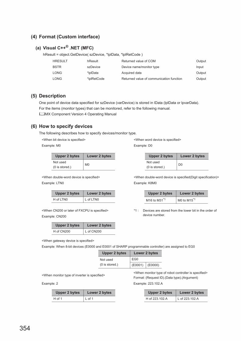
354
(4) Format (Custom interface)
(a) Visual C++® .NET (MFC)
hResult = object.GetDevice( szDevice, *lplData, *lplRetCode )
(5) DescriptionOne point of device data specified for szDevice (varDevice) is stored in lData (lplData or lpvarData).
For the items (monitor types) that can be monitored, refer to the following manual.
MX Component Version 4 Operating Manual
(6) How to specify devicesThe following describes how to specify devices/monitor type.
HRESULT hResult Returned value of COM Output
BSTR szDevice Device name/monitor type Input
LONG *lplData Acquired data Output
LONG *lplRetCode Returned value of communication function Output
<When bit device is specified> <When word device is specified>
Example: M0 Example: D0
<When double-word device is specified> <When double-word device is specified(Digit specification)>
Example: LTN0 Example: K8M0
<When CN200 or later of FXCPU is specified> *1 : Devices are stored from the lower bit in the order of device number.Example: CN200
<When gateway device is specified>
Example: When 8-bit devices (E0000 and E0001 of SHARP programmable controller) are assigned to EG0
<When monitor type of inverter is specified><When monitor type of robot controller is specified>
Format: (Request ID).(Data type).(Argument)
Example: 2 Example: 223.102.A
Upper 2 bytes Lower 2 bytes
Not used
(0 is stored.)M0
Upper 2 bytes Lower 2 bytes
Not used
(0 is stored.)D0
Upper 2 bytes Lower 2 bytes
H of LTN0 L of LTN0
Upper 2 bytes Lower 2 bytes
M16 to M31*1 M0 to M15*1
Upper 2 bytes Lower 2 bytes
H of CN200 L of CN200
Upper 2 bytes Lower 2 bytes
Not used
(0 is stored.)
EG0
(E0001) (E0000)
Upper 2 bytes Lower 2 bytes
H of 1 L of 1
Upper 2 bytes Lower 2 bytes
H of 223.102.A L of 223.102.A

355
CHAPTER 5 FUNCTIONS
5
5.2 Details of F
unctions (For A
CT
Control)
5.2.8 GetD
evice (A
cquiring d
evice data)
(7) Returned valueNormal termination : 0 is returned.
Abnormal termination: Any value other than 0 is returned. (Page 516, CHAPTER 7 ERROR CODES)
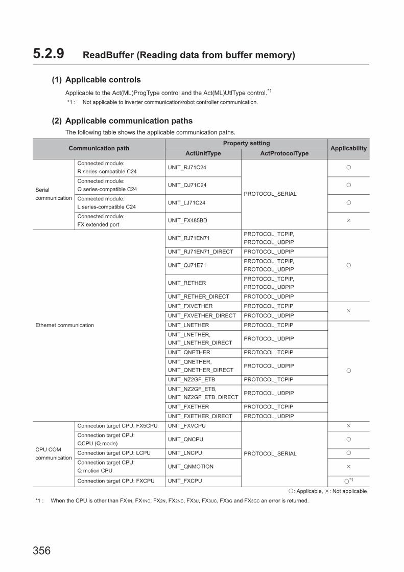
356
5.2.9 ReadBuffer (Reading data from buffer memory)
(1) Applicable controls
Applicable to the Act(ML)ProgType control and the Act(ML)UtlType control.*1
*1 : Not applicable to inverter communication/robot controller communication.
(2) Applicable communication pathsThe following table shows the applicable communication paths.
Communication pathProperty setting
ApplicabilityActUnitType ActProtocolType
Serial
communication
Connected module:
R series-compatible C24UNIT_RJ71C24
PROTOCOL_SERIAL
Connected module:
Q series-compatible C24UNIT_QJ71C24
Connected module:
L series-compatible C24UNIT_LJ71C24
Connected module:
FX extended portUNIT_FX485BD
Ethernet communication
UNIT_RJ71EN71PROTOCOL_TCPIP,
PROTOCOL_UDPIP
UNIT_RJ71EN71_DIRECT PROTOCOL_UDPIP
UNIT_QJ71E71PROTOCOL_TCPIP,
PROTOCOL_UDPIP
UNIT_RETHERPROTOCOL_TCPIP,
PROTOCOL_UDPIP
UNIT_RETHER_DIRECT PROTOCOL_UDPIP
UNIT_FXVETHER PROTOCOL_TCPIP
UNIT_FXVETHER_DIRECT PROTOCOL_UDPIP
UNIT_LNETHER PROTOCOL_TCPIP
UNIT_LNETHER,
UNIT_LNETHER_DIRECTPROTOCOL_UDPIP
UNIT_QNETHER PROTOCOL_TCPIP
UNIT_QNETHER,
UNIT_QNETHER_DIRECTPROTOCOL_UDPIP
UNIT_NZ2GF_ETB PROTOCOL_TCPIP
UNIT_NZ2GF_ETB,
UNIT_NZ2GF_ETB_DIRECTPROTOCOL_UDPIP
UNIT_FXETHER PROTOCOL_TCPIP
UNIT_FXETHER_DIRECT PROTOCOL_UDPIP
CPU COM
communication
Connection target CPU: FX5CPU UNIT_FXVCPU
PROTOCOL_SERIAL
Connection target CPU:
QCPU (Q mode)UNIT_QNCPU
Connection target CPU: LCPU UNIT_LNCPU
Connection target CPU:
Q motion CPUUNIT_QNMOTION
Connection target CPU: FXCPU UNIT_FXCPU *1
: Applicable, : Not applicable
*1 : When the CPU is other than FX1N, FX1NC, FX2N, FX2NC, FX3U, FX3UC, FX3G and FX3GC an error is returned.

357
CHAPTER 5 FUNCTIONS
5
5.2 Details of F
unctions (For A
CT
Control)
5.2.9 ReadB
uffer (Reading data from
buffer mem
ory)
USB
communication
Connection target CPU: RCPU UNIT_RUSB
PROTOCOL_USB
Connection target CPU:
QCPU (Q mode)UNIT_QNUSB
Connection target CPU: LCPU UNIT_LNUSB
Connection target CPU: QSCPU UNIT_QSUSB
Connection target CPU:
Q motion CPUUNIT_QNMOTIONUSB
Connection target CPU: FXCPU UNIT_FXCPU
MELSECNET/H communication UNIT_MNETHBOARD PROTOCOL_MNETH
*2CC-Link IE Controller Network communication UNIT_MNETGBOARD PROTOCOL_MNETG
CC-Link IE Field Network communication UNIT_CCIEFBOARD PROTOCOL_CCIEF
CC-Link communication UNIT_CCLINKBOARD PROTOCOL_CCLINK
CC-Link G4 communication UNIT_G4QCPU PROTOCOL_SERIAL
GX Simulator communication UNIT_SIMULATOR PROTOCOL_SHAREDMEMORY *3
GX Simulator2 communication UNIT_SIMULATOR2 –
MT Simulator2 communication UNIT_SIMULATOR2 –
Modem
communication
Connected module:
Q series-compatible C24UNIT_QJ71C24 PROTOCOL_SERIALMODEM
Connected module:
L series-compatible C24UNIT_LJ71C24 PROTOCOL_SERIALMODEM
Connection target CPU: FXCPU UNIT_FXCPU PROTOCOL_TEL *1
Gateway function communication UNIT_A900GOT PROTOCOL_UDPIP
GOT transparent function communication
UNIT_RJ71C24,
UNIT_QNCPU,
UNIT_LNCPU
PROTOCOL_SERIAL,
PROTOCOL_USBGOT
UNIT_FXCPU *1
UNIT_QJ71C24,
UNIT_LJ71C24,
UNIT_GOT_RJ71EN71,
UNIT_GOT_QJ71E71,
UNIT_GOT_RETHER,
UNIT_GOT_QNETHER,
UNIT_GOT_LNETHER,
UNIT_A900GOT,
UNIT_GOT_NZ2GF_ETB,
UNIT_GOT_FXETHER,
UNIT_GOT_FXENET
UNIT_GOTETHER_RJ71C24,
UNIT_GOTETHER_QNCPU,
UNIT_GOTETHER_LNCPU PROTOCOL_TCPIP
UNIT_GOTETHER_FXCPU *1
UNIT_GOTETHER_QBUS
Q series bus communication UNIT_QBF PROTOCOL_QBF
Inverter communication –COMM_RS232C,
COMM_USB
: Applicable, : Not applicable
*1 : When the CPU is other than FX1N, FX1NC, FX2N, FX2NC, FX3U, FX3UC, FX3G and FX3GC an error is returned.*2 : An error is returned when the own board is accessed.*3 : When the CPU is other than FX0N, FX1N, FX1NC, FX2, FX2C, FX2N, FX2NC, FX3U, FX3UC, FX3G and FX3GC an error is returned.
Communication pathProperty setting
ApplicabilityActUnitType ActProtocolType

358
(3) FeatureRead data from the buffer memory of special function module.
(4) Format (Dispatch interface)
(a) VBA
lRet = object.ReadBuffer(lStartIO, lAddress, lReadSize, iData(0))
(b) Visual C++® .NET (MFC)
lRet = object.ReadBuffer(lStartIO, lAddress, lReadSize, *lpsData)
(c) VBScript
varRet = object.ReadBuffer(varStartIO, varAddress, varReadSize, lpvarData)
(d) Visual Basic® .NET
IRet = object.ReadBuffer(iStartIO, iAddress, iReadSize, iData(0))
Long lRet Returned value Output
Long lStartIOStart I/O number of module from
which values are readInput
Long lAddress Buffer memory address Input
Long lReadSize Read size Input
Integer iData(n) Values read from buffer memory Output
Long lRet Returned value Output
Long lStartIOStart I/O number of module from
which values are readInput
Long lAddress Buffer memory address Input
Long lReadSize Read size Input
Short *lpsData Values read from buffer memory Output
VARIANT varRet Returned value (LONG type) Output
VARIANT varStartIOStart I/O number of module from
which values are read (LONG type)Input
VARIANT varAddress Buffer memory address (LONG type) Input
VARIANT varReadSize Read size (LONG type) Input
VARIANT lpvarDataValues read from buffer memory
(SHORT array type)Output
Integer lRet Returned value Output
Integer iStartIOStart I/O number of module from
which values are readInput
Integer iAddress Buffer memory address Input
Integer iReadSize Read size Input
short iData(n) Values read from buffer memory Output

359
CHAPTER 5 FUNCTIONS
5
5.2 Details of F
unctions (For A
CT
Control)
5.2.9 ReadB
uffer (Reading data from
buffer mem
ory)
(e) Visual C++® .NET
iRet = object.ReadBuffer(iStartIO, iAddress, iReadSize, *ipsData)
(f) Visual C#® .NET
iRet = object.ReadBuffer(iStartIO, iAddress, iReadSize, out sData(0))
(5) Format (Custom interface)
(a) Visual C++® .NET (MFC)
hResult = object.ReadBuffer( lStartIO, lAddress, lReadSize, *lpsData, *lplRetCode )
(6) Description • For the start I/O number of the module specified for lStartIO (varStartIO), specify the value of the actual start
I/O number divided by 16.
• Buffer values of buffer memory address specified for lAddress (varAddress) of the special function module of
the start I/O number specified for lStartIO (varStartIO) are read for the size of lReadSize (varReadSize).
• When performing CPU COM communication with FXCPU as a connected station or GX Simulator
communication, specify the block number (0 to 7) of the special expansion equipment for the module's start
I/O number and any value between 0 and 32767 for the buffer memory address.
• For lData (lplData or lpvarData), reserve arrays for more than the amount specified for lReadSize
(varReadSize).
(7) Returned valueNormal termination : 0 is returned.
Abnormal termination: Any value other than 0 is returned. (Page 516, CHAPTER 7 ERROR CODES)
int iRet Returned value Output
int iStartIOStart I/O number of module from
which values are readInput
int iAddress Buffer memory address Input
int iReadSize Read size Input
short *ipsData Values read from buffer memory Output
int iRet Returned value Output
int iStartIOStart I/O number of module from
which values are readInput
int iAddress Buffer memory address Input
int iReadSize Read size Input
short(n) sData Values read from buffer memory Output
HRESULT hResult Returned value of COM Output
LONG lStartIOStart I/O number of module from
which values are readInput
LONG lAddress Buffer memory address Input
LONG lReadSize Read size Input
SHORT *lpsData Values read from buffer memory Output
LONG *lplRetCode Returned value of communication function Output

360
(8) Considerations for reading/writing data from/to buffer memory in multiple CPU
system configurationAny of the following errors occurs when the function is executed under the situation where the configured multiple
CPU system differs from the I/O assignment set in GX Developer.
Execute the function after checking the I/O assignment set in GX Developer and checking the I/O numbers of the
module from/to which values are read/written.
• An error occurs even when the function is executed after the correct I/O numbers are specified.
• When the specific I/O numbers (I/O numbers whose I/O assignment is actually wrong) are specified,
data can be read from buffer memory normally, but an error (error code: 0x010A4030, 0x010A4042, etc.)
occurs when data are written to the buffer memory.
• Though a programmable controller CPU error (parameter error, SP. UNIT LAY ERR, etc.) does not occur in
the multiple CPU system, an error occurs in the user application when the function is executed.
● If an RCPU, R motion CPU, or Q motion CPU is accessed, an error will be returned.
● For iData (lpsData or lpvarData), reserve a memory area for the number of points specified for lReadSize (varReadSize).If the memory area is not reserved, a critical error (an application error or the like) may occur.
● When reading data from buffer memory (ReadBuffer) on QCPU (Q mode), the read operation can only be performed on the Q series-dedicated modules.Furthermore, data cannot be read from the shared memory of QCPU (Q mode).

361
CHAPTER 5 FUNCTIONS
5
5.2 Details of F
unctions (For A
CT
Control)
5.2.10 WriteB
uffer (Writing data to buffer m
em
ory)
5.2.10 WriteBuffer (Writing data to buffer memory)
(1) Applicable controls
Applicable to the Act(ML)ProgType control and the Act(ML)UtlType control.*1
*1 : Not applicable to inverter communication/robot controller communication.
(2) Applicable communication pathsThe following table shows the applicable communication paths.
Communication pathProperty setting
ApplicabilityActUnitType ActProtocolType
Serial
communication
Connected module:
R series-compatible C24UNIT_RJ71C24
PROTOCOL_SERIAL
Connected module:
Q series-compatible C24UNIT_QJ71C24
Connected module:
L series-compatible C24UNIT_LJ71C24
Connected module:
FX extended portUNIT_FX485BD
Ethernet communication
UNIT_RJ71EN71PROTOCOL_TCPIP,
PROTOCOL_UDPIP
UNIT_RJ71EN71_DIRECT PROTOCOL_UDPIP
UNIT_QJ71E71PROTOCOL_TCPIP,
PROTOCOL_UDPIP
UNIT_RETHERPROTOCOL_TCPIP,
PROTOCOL_UDPIP
UNIT_RETHER_DIRECT PROTOCOL_UDPIP
UNIT_FXVETHER PROTOCOL_TCPIP
UNIT_FXVETHER_DIRECT PROTOCOL_UDPIP
UNIT_LNETHER PROTOCOL_TCPIP
UNIT_LNETHER,
UNIT_LNETHER_DIRECTPROTOCOL_UDPIP
UNIT_QNETHER PROTOCOL_TCPIP
UNIT_QNETHER,
UNIT_QNETHER_DIRECTPROTOCOL_UDPIP
UNIT_NZ2GF_ETB PROTOCOL_TCPIP
UNIT_NZ2GF_ETB,
UNIT_NZ2GF_ETB_DIRECTPROTOCOL_UDPIP
UNIT_FXETHER PROTOCOL_TCPIP
UNIT_FXETHER_DIRECT PROTOCOL_UDPIP
CPU COM
communication
Connection target CPU: FX5CPU UNIT_FXVCPU
PROTOCOL_SERIAL
Connection target CPU:
QCPU (Q mode)UNIT_QNCPU
Connection target CPU: LCPU UNIT_LNCPU
Connection target CPU:
Q motion CPUUNIT_QNMOTION
Connection target CPU: FXCPU UNIT_FXCPU *1
: Applicable, : Not applicable
*1 : When the CPU is other than FX1N, FX1NC, FX2N, FX2NC, FX3U, FX3UC, FX3G and FX3GC an error is returned.

362
USB
communication
Connection target CPU: RCPU UNIT_RUSB
PROTOCOL_USB
Connection target CPU:
QCPU (Q mode)UNIT_QNUSB
Connection target CPU: LCPU UNIT_LNUSB
Connection target CPU: QSCPU UNIT_QSUSB *2
Connection target CPU:
Q motion CPUUNIT_QNMOTIONUSB
Connection target CPU: FXCPU UNIT_FXCPU
MELSECNET/H communication UNIT_MNETHBOARD PROTOCOL_MNETH
*3CC-Link IE Controller Network communication UNIT_MNETGBOARD PROTOCOL_MNETG
CC-Link IE Field Network communication UNIT_CCIEFBOARD PROTOCOL_CCIEF
CC-Link communication UNIT_CCLINKBOARD PROTOCOL_CCLINK
CC-Link G4 communication UNIT_G4QCPU PROTOCOL_SERIAL
GX Simulator communication UNIT_SIMULATOR PROTOCOL_SHAREDMEMORY *4
GX Simulator2 communication UNIT_SIMULATOR2 –
MT Simulator2 communication UNIT_SIMULATOR2 –
Modem
communication
Connected module:
Q series-compatible C24UNIT_QJ71C24 PROTOCOL_SERIALMODEM
Connected module:
L series-compatible C24UNIT_LJ71C24 PROTOCOL_SERIALMODEM
Connection target CPU: FXCPU UNIT_FXCPU PROTOCOL_TEL *1
Gateway function communication UNIT_A900GOT PROTOCOL_UDPIP
GOT transparent function communication
UNIT_RJ71C24,
UNIT_QNCPU,
UNIT_LNCPU
PROTOCOL_SERIAL,
PROTOCOL_USBGOT
UNIT_FXCPU *1
UNIT_QJ71C24,
UNIT_LJ71C24,
UNIT_GOT_RJ71EN71
UNIT_GOT_QJ71E71,
UNIT_GOT_RETHER
UNIT_GOT_QNETHER,
UNIT_GOT_LNETHER,
UNIT_A900GOT,
UNIT_GOT_NZ2GF_ETB,
UNIT_GOT_FXETHER,
UNIT_GOT_FXENET
UNIT_GOTETHER_RJ71C24,
UNIT_GOTETHER_QNCPU,
UNIT_GOTETHER_LNCPU PROTOCOL_TCPIP
UNIT_GOTETHER_FXCPU *1
UNIT_GOTETHER_QBUS
Q series bus communication UNIT_QBF PROTOCOL_QBF
Inverter communication –COMM_RS232C,
COMM_USB
: Applicable, : Not applicable
*1 : When the CPU is other than FX1N, FX1NC, FX2N, FX2NC, FX3U, FX3UC, FX3G and FX3GC an error is returned.*2 : The error code "0x010A42A0" (the access password mismatch) is returned when accessing QSCPU.*3 : An error is returned when the own board is accessed.*4 : When the CPU is other than FX0N, FX1N, FX1NC, FX2, FX2C, FX2N, FX2NC, FX3U, FX3UC, FX3G and FX3GC an error is returned.
Communication pathProperty setting
ApplicabilityActUnitType ActProtocolType

363
CHAPTER 5 FUNCTIONS
5
5.2 Details of F
unctions (For A
CT
Control)
5.2.10 WriteB
uffer (Writing data to buffer m
em
ory)
(3) FeatureWrite data to the buffer memory of special function module.
(4) Format (Dispatch interface)
(a) VBA
lRet = object.WriteBuffer(lStartIO, lAddress, lWriteSize, iData(0))
(b) Visual C++® .NET (MFC)
lRet = object.WriteBuffer(lStartIO, lAddress, lWriteSize, *lpsData)
(c) VBScript
varRet = object.WriteBuffer(varStartIO, varAddress, varWriteSize, varData)
(d) Visual Basic® .NET
IRet = object.WriteBuffer(iStartIO, iAddress, iWriteSize, iData(0))
Long lRet Returned value Output
Long lStartIOStart I/O number of module to
which values are writtenInput
Long lAddress Buffer memory address Input
Long lWriteSize Write size Input
Integer iData(n) Values written from buffer memory Input
Long lRet Returned value Output
Long lStartIOStart I/O number of module to
which values are writtenInput
Long lAddress Buffer memory address Input
Long lWriteSize Write size Input
Short *lpsData Values written from buffer memory Input
VARIANT varRet Returned value (LONG type) Output
VARIANT varStartIOStart I/O number of module to
which values are written (LONG type)Input
VARIANT varAddress Buffer memory address (LONG type) Input
VARIANT varWriteSize Write size (LONG type) Input
VARIANT varDataValues written from buffer memory
(SHORT array type)Input
Integer lRet Returned value Output
Integer iStartIOStart I/O number of module to
which values are writtenInput
Integer iAddress Buffer memory address Input
Integer iWriteSize Write size Input
Short iData(n) Values written from buffer memory Input

364
(e) Visual C++® .NET
iRet = object.WriteBuffer(iStartIO, iAddress, iWriteSize, *ipsData)
(f) Visual C#® .NET
iRet = object.WriteBuffer(iStartIO, iAddress, iWriteSize, ref sData(0))
(5) Format (Custom interface)
(a) Visual C++® .NET (MFC)
hResult = object.WriteBuffer( lStartIO, lAddress, lWriteSize, *lpsData, *lplRetCode )
(6) Description • For the start I/O number of the module specified for lStartIO (varStartIO), specify the value of the actual start
I/O number divided by 16.
• Buffer values of buffer memory address specified for lAddress (varAddress) of the special function module of
the start I/O number specified for lStartIO (varStartIO) are written for the size of lWriteSize (varWriteSize).
• When performing CPU COM communication with FXCPU as a connected station or GX Simulator
communication, specify the block number (0 to 7) of the special expansion equipment for the module's start
I/O number and any value between 0 and 32767 for the buffer memory address.
• For lData (lpsData or varData), reserve arrays for more than the amount specified for lWriteSize
(varWriteSize).
(7) Returned valueNormal termination : 0 is returned.
Abnormal termination: Any value other than 0 is returned. (Page 516, CHAPTER 7 ERROR CODES)
int iRet Returned value Output
int iStartIOStart I/O number of module to
which values are writtenInput
int iAddress Buffer memory address Input
int iWriteSize Write size Input
Short *ipsData Values written from buffer memory Input
int iRet Returned value Output
int iStartIOStart I/O number of module to
which values are writtenInput
int iAddress Buffer memory address Input
int iWriteSize Write size Input
short(n) sData Values written from buffer memory Input
HRESULT hResult Returned value of COM Output
LONG lStartIOStart I/O number of module to
where values are writtenInput
LONG lAddress Buffer memory address Input
LONG lWriteSize Write size Input
SHORT *lpsData Values written from buffer memory Input
LONG *lplRetCode Returned value of communication function Output
365
CHAPTER 5 FUNCTIONS
5
5.2 Details of F
unctions (For A
CT
Control)
5.2.10 WriteB
uffer (Writing data to buffer m
em
ory)
(8) Considerations for reading/writing data from/to buffer memory in multiple CPU
system configurationAny of the following errors occurs when the function is executed under the situation where the configured multiple
CPU system differs from the I/O assignment set in GX Developer.
Execute the function after checking the I/O assignment set in GX Developer and checking the I/O numbers of the
module from/to which the values are read/written.
• An error occurs even when the function is executed after the correct I/O numbers are specified.
• When the specific I/O numbers (I/O numbers whose I/O assignment is actually wrong) are specified,
data can be read from buffer memory normally, but an error (error code: 0x010A4030, 0x010A4042, etc.)
occurs when data are written to the buffer memory.
• Though a programmable controller CPU error (parameter error, SP. UNIT LAY ERR, etc.) does not occur in
the multiple CPU system, an error occurs in the user application when the function is executed.
● If an RCPU, R motion CPU, or Q motion CPU is accessed, an error will be returned.
● For iData (lpsData, varData), reserve a memory area for the number of points specified for lWriteSize (varWriteSize).If the memory area is not reserved, a critical error (an application error or the like) may occur.
● When buffer memory write (WriteBuffer) is performed for QCPU (Q mode), write operation may be performed for only the Q series-dedicated module.Furthermore, data cannot be written to the shared memory of QCPU (Q mode).

366
5.2.11 GetClockData (Reading clock data)
(1) Applicable controls
Applicable to the Act(ML)ProgType control and the Act(ML)UtlType control.*1
*1 : Not applicable to inverter communication/robot controller communication.
(2) Applicable communication pathsThe following table shows the applicable communication paths.
Communication pathProperty setting
ApplicabilityActUnitType ActProtocolType
Serial
communication
Connected module:
R series-compatible C24UNIT_RJ71C24
PROTOCOL_SERIAL
Connected module:
Q series-compatible C24UNIT_QJ71C24
Connected module:
L series-compatible C24UNIT_LJ71C24
Connected module:
FX extended portUNIT_FX485BD
Ethernet communication
UNIT_RJ71EN71PROTOCOL_TCPIP,
PROTOCOL_UDPIP
UNIT_RJ71EN71_DIRECT PROTOCOL_UDPIP
UNIT_QJ71E71PROTOCOL_TCPIP,
PROTOCOL_UDPIP
UNIT_RETHERPROTOCOL_TCPIP,
PROTOCOL_UDPIP
UNIT_RETHER_DIRECT PROTOCOL_UDPIP
UNIT_FXVETHER PROTOCOL_TCPIP
UNIT_FXVETHER_DIRECT PROTOCOL_UDPIP
UNIT_LNETHER PROTOCOL_TCPIP
UNIT_LNETHER,
UNIT_LNETHER_DIRECTPROTOCOL_UDPIP
UNIT_QNETHER PROTOCOL_TCPIP
UNIT_QNETHER,
UNIT_QNETHER_DIRECTPROTOCOL_UDPIP
UNIT_NZ2GF_ETB PROTOCOL_TCPIP
UNIT_NZ2GF_ETB,
UNIT_NZ2GF_ETB_DIRECTPROTOCOL_UDPIP
UNIT_FXETHER PROTOCOL_TCPIP
UNIT_FXETHER_DIRECT PROTOCOL_UDPIP
CPU COM
communication
Connection target CPU: FX5CPU UNIT_FXVCPU
PROTOCOL_SERIAL
Connection target CPU:
QCPU (Q mode)UNIT_QNCPU
Connection target CPU: LCPU UNIT_LNCPU
Connection target CPU:
Q motion CPUUNIT_QNMOTION
Connection target CPU: FXCPU UNIT_FXCPU
: Applicable, : Not applicable

367
CHAPTER 5 FUNCTIONS
5
5.2 Details of F
unctions (For A
CT
Control)
5.2.11 GetC
lockData (R
eading clock data)
USB
communication
Connection target CPU: RCPU UNIT_RUSB
PROTOCOL_USB
Connection target CPU:
QCPU (Q mode)UNIT_QNUSB
Connection target CPU: LCPU UNIT_LNUSB
Connection target CPU: QSCPU UNIT_QSUSB
Connection target CPU:
Q motion CPUUNIT_QNMOTIONUSB
Connection target CPU: FXCPU UNIT_FXCPU
MELSECNET/H communication UNIT_MNETHBOARD PROTOCOL_MNETH
*1CC-Link IE Controller Network communication UNIT_MNETGBOARD PROTOCOL_MNETG
CC-Link IE Field Network communication UNIT_CCIEFBOARD PROTOCOL_CCIEF
CC-Link communication UNIT_CCLINKBOARD PROTOCOL_CCLINK
CC-Link G4 communication UNIT_G4QCPU PROTOCOL_SERIAL
GX Simulator communication UNIT_SIMULATOR PROTOCOL_SHAREDMEMORY
GX Simulator2 communication UNIT_SIMULATOR2 –
MT Simulator2 communication UNIT_SIMULATOR2 –
Modem
communication
Connected module:
Q series-compatible C24UNIT_QJ71C24 PROTOCOL_SERIALMODEM
Connected module:
L series-compatible C24UNIT_LJ71C24 PROTOCOL_SERIALMODEM
Connection target CPU: FXCPU UNIT_FXCPU PROTOCOL_TEL
Gateway function communication UNIT_A900GOT PROTOCOL_UDPIP
GOT transparent function communication
UNIT_RJ71C24,
UNIT_QNCPU,
UNIT_LNCPU,
UNIT_FXCPU,
UNIT_QJ71C24,
UNIT_LJ71C24,
UNIT_GOT_RJ71EN71,
UNIT_GOT_QJ71E71,
UNIT_GOT_RETHER,
UNIT_GOT_QNETHER,
UNIT_GOT_LNETHER,
UNIT_A900GOT,
UNIT_GOT_NZ2GF_ETB,
UNIT_GOT_FXETHER,
UNIT_GOT_FXENET
PROTOCOL_SERIAL,
PROTOCOL_USBGOT
UNIT_GOTETHER_RJ71C24,
UNIT_GOTETHER_QNCPU,
UNIT_GOTETHER_LNCPU,
UNIT_GOTETHER_FXCPU,
UNIT_GOTETHER_QBUS
PROTOCOL_TCPIP
Q series bus communication UNIT_QBF PROTOCOL_QBF
Inverter communication –COMM_RS232C,
COMM_USB
: Applicable, : Not applicable
*1 : An error is returned when the own board is accessed.
Communication pathProperty setting
ApplicabilityActUnitType ActProtocolType

368
(3) FeatureRead clock data from a programmable controller CPU.
(4) Format (Dispatch interface)
(a) VBA
lRet = object.GetClockData(iYear, iMonth, iDay, iDayOfWeek, iHour, iMinute, iSecond)
(b) Visual C++® .NET (MFC)
lRet = object.GetClockData(*lpsYear, *lpsMonth, *lpsDay,*lpsDayOfWeek, *lpsHour, *lpsMinute, *lpsSecond)
(c) VBScript
varRet = object.GetClockData(lpvarYear, lpvarMonth, lpvarDay, lpvarDayOfWeek, lpvarHour, lpvarMinute,
lpvarSecond)
Long lRet Returned value Output
Integer iYear Read year value Output
Integer iMonth Read month value Output
Integer iDay Read day value Output
Integer iDayOfWeek(n) Read day-of-week value Output
Integer iHour Read hour value Output
Integer iMinute Read minute value Output
Integer iSecond Read second value Output
Long lRet Returned value Output
Short *lpsYear Read year value Output
Short *lpsMonth Read month value Output
Short *lpsDay Read day value Output
Short *lpsDayOfWeek Read day-of-week value Output
Short *lpsHour Read hour value Output
Short *lpsMinute Read minute value Output
Short *lpsSecond Read second value Output
VARIANT varRet Returned value (LONG type) Output
VARIANT lpvarYear Read year value (SHORT type) Output
VARIANT lpvarMonth Read month value (SHORT type) Output
VARIANT lpvarDay Read day value (SHORT type) Output
VARIANT lpvarDayOfWeek Read day-of-week value (SHORT type) Output
VARIANT lpvarHour Read hour value (SHORT type) Output
VARIANT lpvarMinute Read minute value (SHORT type) Output
VARIANT lpvarSecond Read second value (SHORT type) Output

369
CHAPTER 5 FUNCTIONS
5
5.2 Details of F
unctions (For A
CT
Control)
5.2.11 GetC
lockData (R
eading clock data)
(d) Visual Basic® .NET
IRet = object.GetClockData(iYear, iMonth, iDay, iDayOfWeek, iHour, iMinute, iSecond)
(e) Visual C++® .NET
iRet = object.GetClockData(*lpsYear, *lpsMonth, *lpsDay, *lpsDayOfWeek, *lpsHour, *lpsMinute, *lpsSecond)
(f) Visual C#® .NET
hResult = object.GetClockData(out sYear, out sMonth, out sDay, out sDayOfWeek, out sHour, out sMinute,
out sSecond)
Integer lRet Returned value Output
short iYear Read year value Output
short iMonth Read month value Output
short iDay Read day value Output
short iDayOfWeek Read day-of-week value Output
short iHour Read hour value Output
short iMinute Read minute value Output
short iSecond Read second value Output
int iRet Returned value Output
short *lpsYear Read year value Output
short *lps Month Read month value Output
short *lps Day Read day value Output
short *lps DayOfWeek Read day-of-week value Output
short *lps Hour Read hour value Output
short *lps Minute Read minute value Output
short *lps Second Read second value Output
int iRet Returned value Output
short sYear Read year value Output
short sMonth Read month value Output
short sDay Read day value Output
short sDayOfWeek Read day-of-week value Output
short sHour Read hour value Output
short sMinute Read minute value Output
short sSecond Read second value Output

370
(5) Format (Custom interface)
(a) Visual C++® .NET (MFC)
hResult = object.GetClockData( *lpsYear, *lpsMonth, *lpsDay, *lpsDayOfWeek, *lpsHour, *lpsMinute,
*lpsSecond, *lplRetCode )
(6) Description • An error is returned when the correct clock data is not set to the programmable controller CPU.
• The values stored in iYear (lpsYear or lpvarYear) are: four digits of the year for RCPU and QCPU (Q mode)
and last two digits of the year for any other CPUs.
Note that the applicable years for RCPU and QCPU (Q mode) are from 1980 to 2079.
• The values stored in iDayOfWeek (lpsDayOfWeek or lpvarDayOfWeek) are as follows.
(7) Returned valueNormal termination : 0 is returned.
Abnormal termination: Any value other than 0 is returned. (Page 516, CHAPTER 7 ERROR CODES)
● If an R motion CPU or a Q motion CPU is accessed, an error is returned.
● The clock data can be read from FXCPUs with the built-in clock or FXU/FX2C/FX2NC with the RTC cassette.An error is returned when the clock data is read from an FXCPU other than the ones described above.
● Note that an error of transfer time may occur in clock setting.
HRESULT hResult Returned value of COM Output
SHORT *lpsYear Read year value Output
SHORT *lpsMonth Read month value Output
SHORT *lpsDay Read day value Output
SHORT *lpsDayOfWeek Read day-of-week value Output
SHORT *lpsHour Read hour value Output
SHORT *lpsMinute Read minute value Output
SHORT *lpsSecond Read second value Output
LONG *lplRetCode Returned value of communication function Output
Value Day of Week
0 Sunday
1 Monday
2 Tuesday
3 Wednesday
4 Thursday
5 Friday
6 Saturday

371
CHAPTER 5 FUNCTIONS
5
5.2 Details of F
unctions (For A
CT
Control)
5.2.12 Se
tClockD
ata (Writing clo
ck data)
5.2.12 SetClockData (Writing clock data)
(1) Applicable controls
Applicable to the Act(ML)ProgType control and the Act(ML)UtlType control.*1
*1 : Not applicable to inverter communication/robot controller communication.
(2) Applicable communication pathsThe following table shows the applicable communication paths.
Communication pathProperty setting
ApplicabilityActUnitType ActProtocolType
Serial
communication
Connected module:
R series-compatible C24UNIT_RJ71C24
PROTOCOL_SERIAL
Connected module:
Q series-compatible C24UNIT_QJ71C24
Connected module:
L series-compatible C24UNIT_LJ71C24
Connected module:
FX extended portUNIT_FX485BD
Ethernet communication
UNIT_RJ71EN71PROTOCOL_TCPIP,
PROTOCOL_UDPIP
UNIT_RJ71EN71_DIRECT PROTOCOL_UDPIP
UNIT_QJ71E71PROTOCOL_TCPIP,
PROTOCOL_UDPIP
UNIT_RETHERPROTOCOL_TCPIP,
PROTOCOL_UDPIP
UNIT_RETHER_DIRECT PROTOCOL_UDPIP
UNIT_FXVETHER PROTOCOL_TCPIP
UNIT_FXVETHER_DIRECT PROTOCOL_UDPIP
UNIT_LNETHER PROTOCOL_TCPIP
UNIT_LNETHER,
UNIT_LNETHER_DIRECTPROTOCOL_UDPIP
UNIT_QNETHER PROTOCOL_TCPIP
UNIT_QNETHER,
UNIT_QNETHER_DIRECTPROTOCOL_UDPIP
UNIT_NZ2GF_ETB PROTOCOL_TCPIP
UNIT_NZ2GF_ETB,
UNIT_NZ2GF_ETB_DIRECTPROTOCOL_UDPIP
UNIT_FXETHER PROTOCOL_TCPIP
UNIT_FXETHER_DIRECT PROTOCOL_UDPIP
CPU COM
communication
Connection target CPU: FX5CPU UNIT_FXVCPU
PROTOCOL_SERIAL
Connection target CPU:
QCPU (Q mode)UNIT_QNCPU
Connection target CPU: LCPU UNIT_LNCPU
Connection target CPU:
Q motion CPUUNIT_QNMOTION
Connection target CPU: FXCPU UNIT_FXCPU
: Applicable, : Not applicable

372
USB
communication
Connection target CPU: RCPU UNIT_RUSB
PROTOCOL_USB
Connection target CPU:
QCPU (Q mode)UNIT_QNUSB
Connection target CPU: LCPU UNIT_LNUSB
Connection target CPU: QSCPU UNIT_QSUSB *1
Connection target CPU:
Q motion CPUUNIT_QNMOTIONUSB
Connection target CPU: FXCPU UNIT_FXCPU
MELSECNET/H communication UNIT_MNETHBOARD PROTOCOL_MNETH
*2CC-Link IE Controller Network communication UNIT_MNETGBOARD PROTOCOL_MNETG
CC-Link IE Field Network communication UNIT_CCIEFBOARD PROTOCOL_CCIEF
CC-Link communication UNIT_CCLINKBOARD PROTOCOL_CCLINK
CC-Link G4 communication UNIT_G4QCPU PROTOCOL_SERIAL
GX Simulator communication UNIT_SIMULATOR PROTOCOL_SHAREDMEMORY
GX Simulator2 communication UNIT_SIMULATOR2 –
MT Simulator2 communication UNIT_SIMULATOR2 –
Modem
communication
Connected module:
Q series-compatible C24UNIT_QJ71C24 PROTOCOL_SERIALMODEM
Connected module:
L series-compatible C24UNIT_LJ71C24 PROTOCOL_SERIALMODEM
Connection target CPU: FXCPU UNIT_FXCPU PROTOCOL_TEL
Gateway function communication UNIT_A900GOT PROTOCOL_UDPIP
GOT transparent function communication
UNIT_RJ71C24,
UNIT_QNCPU,
UNIT_LNCPU,
UNIT_FXCPU,
UNIT_QJ71C24,
UNIT_LJ71C24,
UNIT_GOT_RJ71EN71,
UNIT_GOT_QJ71E71,
UNIT_GOT_RETHER,
UNIT_GOT_QNETHER,
UNIT_GOT_LNETHER,
UNIT_A900GOT,
UNIT_GOT_NZ2GF_ETB,
UNIT_GOT_FXETHER,
UNIT_GOT_FXENET
PROTOCOL_SERIAL,
PROTOCOL_USBGOT
UNIT_GOTETHER_RJ71C24,
UNIT_GOTETHER_QNCPU,
UNIT_GOTETHER_LNCPU,
UNIT_GOTETHER_FXCPU,
UNIT_GOTETHER_QBUS
PROTOCOL_TCPIP
Q series bus communication UNIT_QBF PROTOCOL_QBF
Inverter communication –COMM_RS232C,
COMM_USB
: Applicable, : Not applicable
*1 : The error code "0x010A42A0" (the access password mismatch) is returned when accessing QSCPU.*2 : An error is returned when the own board is accessed.
Communication pathProperty setting
ApplicabilityActUnitType ActProtocolType

373
CHAPTER 5 FUNCTIONS
5
5.2 Details of F
unctions (For A
CT
Control)
5.2.12 Se
tClockD
ata (Writing clo
ck data)
(3) FeatureWrite clock data to a programmable controller CPU.
(4) Format (Dispatch interface)
(a) VBA
lRet = object.SetClockData(iYear, iMonth, iDay, iDayOfWeek, iHour, iMinute, iSecond)
(b) Visual C++® .NET (MFC)
lRet = object.SetClockData(sYear, sMonth, sDay, sDayOfWeek, sHour, sMinute, sSecond)
(c) VBScript
varRet = object.SetClockData(varYear, varMonth, varDay, varDayOfWeek,varHour, varMinute, varSecond)
Long lRet Returned value Output
Integer iYear Year value to be written Input
Integer iMonth Month value to be written Input
Integer iDay Day value to be written Input
Integer iDayOfWeek(n) Day-of-week value to be written Input
Integer iHour Hour value to be written Input
Integer iMinute Minute value to be written Input
Integer iSecond Second value to be written Input
Long lRet Returned value Output
Short sYear Year value to be written Input
Short sMonth Month value to be written Input
Short sDay Day value to be written Input
Short sDayOfWeek Day-of-week value to be written Input
Short sHour Hour value to be written Input
Short sMinute Minute value to be written Input
Short sSecond Second value to be written Input
VARIANT varRet Returned value (LONG type) Output
VARIANT varYear Year value to be written (SHORT type) Input
VARIANT varMonth Month value to be written (SHORT type) Input
VARIANT varDay Day value to be written (SHORT type) Input
VARIANT varDayOfWeek Day-of-week value to be written (SHORT type) Input
VARIANT varHour Hour value to be written (SHORT type) Input
VARIANT varMinute Minute value to be written (SHORT type) Input
VARIANT varSecond Second value to be written (SHORT type) Input

374
(d) Visual Basic® .NET
IRet = object.SetClockData(iYear, iMonth, iDay, iDayOfWeek, iHour, iMinute, iSecond)
(e) Visual C++® .NET
iRet = object.SetClockData(sYear, sMonth, sDay, sDayOfWeek, sHour, sMinute, sSecond)
(f) Visual C#® .NET
IRet = object.SetClockData(sYear, sMonth, sDay, sDayOfWeek, sHour, sMinute, sSecond)
(5) Format (Custom interface)
(a) Visual C++® .NET (MFC)
hResult = object.SetClockData(sYear,sMonth, sDay, sDayOfWeek, sHour, sMinute, sSecond,
*lplRetCode )
Integer lRet Returned value Output
short iYear Year value to be written Input
short iMonth Month value to be written Input
short iDay Day value to be written Input
short iDayOfWeek Day-of-week value to be written Input
short iHour Hour value to be written Input
short iMinute Minute value to be written Input
short iSecond Second value to be written Input
int iRet Returned value Output
short sYear Year value to be written Input
short sMonth Month value to be written Input
short sDay Day value to be written Input
short sDayOfWeek Day-of-week value to be written Input
short sHour Hour value to be written Input
short sMinute Minute value to be written Input
short sSecond Second value to be written Input
HRESULT hResult Returned value of COM Output
SHORT sYear Year value to be written Input
SHORT sMonth Month value to be written Input
SHORT sDay Day value to be written Input
SHORT sDayOfWeek Day-of-week value to be written Input
SHORT sHour Hour value to be written Input
SHORT sMinute Minute value to be written Input
SHORT sSecond Second value to be written Input
LONG *lplRetCode Returned value of communication function Output

375
CHAPTER 5 FUNCTIONS
5
5.2 Details of F
unctions (For A
CT
Control)
5.2.12 Se
tClockD
ata (Writing clo
ck data)
(6) Description • An error is returned when the clock data to be set are not correct values.
• The applicable values to be specified for iYear (sYear or varYear) are: four digits of the year for RCPU and
QCPU (Q mode) and last two digits of the year for any other CPUs.
Note that the applicable years for RCPU and QCPU (Q mode) are from 1980 to 2079.
An error occurs when four digits are set to a CPU other than RCPU and QCPU (Q mode).
• The values to be specified for iDayOfWeek (sDayOfWeek or varDayOfWeek) are as follows.
(7) Returned valueNormal termination : 0 is returned.
Abnormal termination: Any value other than 0 is returned. (Page 516, CHAPTER 7 ERROR CODES)
● If an R motion CPU or a Q motion CPU is accessed, an error is returned.
● The clock data can be written to FXCPUs with the built-in clock or FXU/FX2C/FX2NC with the RTC cassette.An error is returned when the clock data is written to an FXCPU other than the ones described above.
● Note that an error of transfer time may occur in clock setting.
Value Day of Week
0 Sunday
1 Monday
2 Tuesday
3 Wednesday
4 Thursday
5 Friday
6 Saturday

376
5.2.13 GetCpuType (Reading programmable controller CPU model)
(1) Applicable controlsApplicable to the Act(ML)ProgType control and the Act(ML)UtlType control.
(2) FeatureRead the model character string and the model code of programmable controller CPU, network board, and GOT.
(3) Format (Dispatch interface)
(a) VBA
lRet = object.GetCpuType(szCpuName, lCpuType)
(b) Visual C++® .NET (MFC)
lRet = object.GetCpuType(*szCpuName, *lplCpuType)
(c) VBScript
varRet = object.GetCpuType(varCpuName, lpvarCpuCode)
(d) Visual Basic® .NET
IRet = object.GetCpuType(szCpuName, ICpuType)
Long lRet Returned value Output
String szCpuNameProgrammable controller CPU model
character stringOutput
Long lCpuTypeProgrammable controller CPU model
codeOutput
Long lRet Returned value Output
BSTR *szCpuNameProgrammable controller CPU model
character stringOutput
Long *lplCpuTypeProgrammable controller CPU model
codeOutput
VARIANT varRet Returned value (LONG type) Output
VARIANT varCpuNameProgrammable controller CPU model
character string (character string type)Output
VARIANT lpvarCpuCodeProgrammable controller CPU model
code (LONG type)Output
Integer IRet Returned value Output
String szCpuNameProgrammable controller CPU model
character stringOutput
Integer ICpuTypeProgrammable controller CPU model
codeOutput

377
CHAPTER 5 FUNCTIONS
5
5.2 Details of F
unctions (For A
CT
Control)
5.2.13 GetC
puType (R
eading program
mable controller C
PU
mode
l)
(e) Visual C++® .NET
iRet = object.GetCpuType (**szCpuName, *iplCpuType)
(f) Visual C#® .NET
iRet = object.GetCpuType (out szCpuName, out iCpuType)
(4) Format (Custom interface)
(a) Visual C++® .NET (MFC)
hResult = object.GetCpuType( *szCpuName, *lplCpuType, *lplRetCode )
(5) Description • The model and the model code of the communication target programmable controller CPU are stored in
szCpuName (lpvarCpuName) and lCpuType (lplCpuType or lpvarCpuCode) respectively.
• The model character string of the programmable controller CPU is returned in UNICODE.
int iRet Returned value Output
String **szCpuNameProgrammable controller CPU model
character stringOutput
int *iplCpuTypeProgrammable controller CPU model
codeOutput
int iRet Returned value Output
String szCpuNameProgrammable controller CPU model
character stringOutput
int iCpuTypeProgrammable controller CPU model
codeOutput
HRESULT hResult Returned value of COM Output
BSTR *szCpuNameProgrammable controller CPU model character
stringOutput
LONG *lplCpuType Programmable controller CPU model code Output
LONG *lplRetCode Returned value of communication function Output Output

378
(6) Model character string and model code of CPUThe following tables show the model character strings and the model codes of programmable controller CPU,
network board, and GOT, which are read by the GetCpuType function.
CPU/
network board/
GOT
Model character
When CPU/own board is connected When GX Simulator is connected
strings code strings code
R04CPU R04CPU 4800H
–
R08CPU R08CPU 4801H
R16CPU R16CPU 4802H
R32CPU R32CPU 4803H
R120CPU R120CPU 4804H
R16MTCPU R16MTCPU 4C00H
R32MTCPU R32MTCPU 4C01H
FX5CPU FX5CPU 4A00H
Q00JCPU Q00JCPU 250H Q00JCPU 250H
Q00UJCPU Q00UJCPU 260H Q00UJCPU 260H
Q00CPU Q00CPU 251H Q00CPU 251H
Q00UCPU Q00UCPU 261H Q00UCPU 261H
Q01CPU Q01CPU 252H Q01CPU 252H
Q01UCPU Q01UCPU 262H Q01UCPU 262H
Q02CPU Q02CPU
41H
Q02CPU
41HQ02HCPU Q02HCPU Q02HCPU
Q02PHCPU Q02PHCPU Q02PHCPU
Q02UCPU Q02UCPU 263H Q02UCPU 263H
Q03UDCPU Q03UDCPU268H
Q03UDCPU268H
Q03UDECPU Q03UDECPU Q03UDECPU
Q03UDVCPU Q03UDVCPU 366H –
Q04UDHCPU Q04UDHCPU269H
Q04UDHCPU269H
Q04UDEHCPU Q04UDEHCPU Q04UDEHCPU
Q04UDVCPU Q04UDVCPU 367H –
Q06HCPU Q06HCPU42H
Q06HCPU42H
Q06PHCPU Q06PHCPU Q06PHCPU
Q06UDHCPU Q06UDHCPU26AH
Q06UDHCPU26AH
Q06UDEHCPU Q06UDEHCPU Q06UDEHCPU
Q06UDVCPU Q06UDVCPU 368H –
Q10UDHCPU Q10UDHCPU266H
Q10UDHCPU266H
Q10UDEHCPU Q10UDEHCPU Q10UDEHCPU
Q12HCPUQ12HCPU 43H Q12HCPU 43H
Q12PHCPU
Q12PRHCPU Q12PRHCPU 4BH Q12PRHCPU 4BH
Q13UDHCPU Q13UDHCPU26BH
Q13UDHCPU26BH
Q13UDEHCPU Q13UDEHCPU Q13UDEHCPU
Q13UDVCPU Q13UDVCPU 36AH –
Q20UDHCPU Q20UDHCPU267H
Q20UDHCPU267H
Q20UDEHCPU Q20UDEHCPU Q20UDEHCPU

379
CHAPTER 5 FUNCTIONS
5
5.2 Details of F
unctions (For A
CT
Control)
5.2.13 GetC
puType (R
eading program
mable controller C
PU
mode
l)
Q25HCPUQ25HCPU 44H Q25HCPU 44H
Q25PHCPU
Q25PRHCPU Q25PRHCPU 4CH Q25PRHCPU 4CH
Q26UDHCPU Q26UDHCPU26CH
Q26UDHCPU26CH
Q26UDEHCPU Q26UDEHCPU Q26UDEHCPU
Q26UDVCPU Q26UDVCPU 36CH
–Q50UDEHCPU Q50UDEHCPU 26DH
Q100UDEHCPU Q100UDEHCPU 26EH
Q02CPU-A Q02CPU141H Q02CPU-A 141H
Q02HCPU-A Q02HCPU
Q06HCPU-A Q06HCPU 142H Q06HCPU-A 142H
L02SCPU L02SCPU 543H
–
L02CPU L02CPU 541H
L06CPU L06CPU 544H
L26CPU L26CPU 545H
L26CPU-BT L26CPU-BT 542H
Q12DCCPU-V Q12DCCPU-V 2043H
Q24DHCCPU-V Q24DHCCPU-V 2044H
Q24DHCCPU-LS Q24DHCCPU-LS 2045H
QS001CPU QS001CPU 230H
Q172CPU Q172CPU 2010H
Q172HCPU Q172HCPU 2012H
Q173CPU Q173CPU 2011H
Q173HCPU Q173HCPU 2013H
Q172DCPU Q172DCPU 2014H
Q173DCPU Q173DCPU 2015H
Q172DSCPU Q172DSCPU 2018H
Q173DSCPU Q173DSCPU 2019H
FX0FX0/FX0S F0H FX0/FX0S F0H
FX0S
FX0N FX0N 8EH FX0N 8EH
FX1 FX1 F1H FX1 F1H
FX1S FX1S F2H FX1S F2H
FX1NFX1N 9EH FX1N 9EH
FX1NC
FXUFXU/FX2C 8DH FXU/FX2C 8DH
FX2C
FX2NFX2N/FX2NC 9DH FX2N/FX2NC 9DH
FX2NC
FX3S FX3S F5H –
FX3GFX3G F4H FX3G F4H
FX3GC
FX3UFX3UC F3H FX3UC F3H
FX3UC
CPU/
network board/
GOT
Model character
When CPU/own board is connected When GX Simulator is connected
strings code strings code

380
*1 : A product model number of GOT is displayed.
(7) Returned valueNormal termination : 0 is returned.
Abnormal termination: Any value other than 0 is returned. (Page 516, CHAPTER 7 ERROR CODES)
Q80BD-J71LP21-25 Q80BD-J71LP21-25
90H
–
Q80BD-J71LP21G Q80BD-J71LP21G
Q80BD-J71BR11 Q80BD-J71BR11
Q81BD-J71GF11-T2 Q81BD-J71GF11-T2
GOT *1 E340H
A800 0xA8 A8H
CRnD-7xx/CR75x-D CRnD-7xx 03H
CPU/
network board/
GOT
Model character
When CPU/own board is connected When GX Simulator is connected
strings code strings code

381
CHAPTER 5 FUNCTIONS
5
5.2 Details of F
unctions (For A
CT
Control)
5.2.14 Se
tCpuS
tatus (Re
mote co
ntrol)
5.2.14 SetCpuStatus (Remote control)
(1) Applicable controls
Applicable to the Act(ML)ProgType control and the Act(ML)UtlType control.*1
*1 : Not applicable to inverter communication/robot controller communication.
(2) Applicable communication pathsThe following table shows the applicable communication paths.
Communication pathProperty setting
ApplicabilityActUnitType ActProtocolType
Serial
communication
Connected module:
R series-compatible C24UNIT_RJ71C24
PROTOCOL_SERIAL
Connected module:
Q series-compatible C24UNIT_QJ71C24
Connected module:
L series-compatible C24UNIT_LJ71C24
Connected module:
FX extended portUNIT_FX485BD *1, *2
Ethernet communication
UNIT_RJ71EN71PROTOCOL_TCPIP,
PROTOCOL_UDPIP
UNIT_RJ71EN71_DIRECT PROTOCOL_UDPIP
UNIT_QJ71E71PROTOCOL_TCPIP,
PROTOCOL_UDPIP
UNIT_RETHERPROTOCOL_TCPIP,
PROTOCOL_UDPIP
UNIT_RETHER_DIRECT PROTOCOL_UDPIP
UNIT_FXVETHER PROTOCOL_TCPIP*1
UNIT_FXVETHER_DIRECT PROTOCOL_UDPIP
UNIT_LNETHER PROTOCOL_TCPIP
UNIT_LNETHER,
UNIT_LNETHER_DIRECTPROTOCOL_UDPIP
UNIT_QNETHER PROTOCOL_TCPIP
UNIT_QNETHER,
UNIT_QNETHER_DIRECTPROTOCOL_UDPIP
UNIT_NZ2GF_ETB PROTOCOL_TCPIP
UNIT_NZ2GF_ETB
UNIT_NZ2GF_ETB_DIRECTPROTOCOL_UDPIP
UNIT_FXETHER PROTOCOL_TCPIP*1
UNIT_FXETHER_DIRECT PROTOCOL_UDPIP
CPU COM
communication
Connection target CPU: FX5CPU UNIT_FXVCPU
PROTOCOL_SERIAL
*1
Connection target CPU:
QCPU (Q mode)UNIT_QNCPU
Connection target CPU: LCPU UNIT_LNCPU
Connection target CPU:
Q motion CPUUNIT_QNMOTION
Connection target CPU: FXCPU UNIT_FXCPU *1
: Applicable, : Not applicable
*1 : An error is returned when PAUSE is specified.*2 : An error is returned when the CPU is other than FX1N, FX1NC, FX2N, FX2NC, FX3S, FX3U, FX3UC, FX3G and FX3GC.

382
USB
communication
Connection target CPU: RCPU UNIT_RUSB
PROTOCOL_USB
Connection target CPU:
QCPU (Q mode)UNIT_QNUSB
Connection target CPU: LCPU UNIT_LNUSB
Connection target CPU: QSCPU UNIT_QSUSB *3
Connection target CPU:
Q motion CPUUNIT_QNMOTIONUSB
Connection target CPU: FXCPU UNIT_FXCPU *1
MELSECNET/H communication UNIT_MNETHBOARD PROTOCOL_MNETH
*4CC-Link IE Controller Network communication UNIT_MNETGBOARD PROTOCOL_MNETG
CC-Link IE Field Network communication UNIT_CCIEFBOARD PROTOCOL_CCIEF
CC-Link communication UNIT_CCLINKBOARD PROTOCOL_CCLINK
CC-Link G4 communication UNIT_G4QCPU PROTOCOL_SERIAL
GX Simulator communication UNIT_SIMULATOR PROTOCOL_SHAREDMEMORY
GX Simulator2 communication UNIT_SIMULATOR2 –
MT Simulator2 communication UNIT_SIMULATOR2 –
Modem
communication
Connected module:
Q series-compatible C24UNIT_QJ71C24 PROTOCOL_SERIALMODEM
Connected module:
L series-compatible C24UNIT_LJ71C24 PROTOCOL_SERIALMODEM
Connection target CPU: FXCPU UNIT_FXCPU PROTOCOL_TEL *1
Gateway function communication UNIT_A900GOT PROTOCOL_UDPIP
GOT transparent function communication
UNIT_RJ71C24,
UNIT_QNCPU,
UNIT_LNCPU
PROTOCOL_SERIAL,
PROTOCOL_USBGOT
UNIT_FXCPU *1
UNIT_QJ71C24,
UNIT_LJ71C24,
UNIT_GOT_RJ71EN71,
UNIT_GOT_QJ71E71,
UNIT_GOT_RETHER,
UNIT_GOT_QNETHER,
UNIT_GOT_LNETHER,
UNIT_A900GOT,
UNIT_GOT_NZ2GF_ETB
UNIT_GOT_FXETHER,
UNIT_GOT_FXENET*1
UNIT_GOTETHER_RJ71C24,
UNIT_GOTETHER_QNCPU,
UNIT_GOTETHER_LNCPU PROTOCOL_TCPIP
UNIT_GOTETHER_FXCPU *1
UNIT_GOTETHER_QBUS
Q series bus communication UNIT_QBF PROTOCOL_QBF
Inverter communication –COMM_RS232C,
COMM_USB
: Applicable, : Not applicable
*1 : An error is returned when PAUSE is specified.*2 : An error is returned when the CPU is other than FX1N, FX1NC, FX2N, FX2NC, FX3S, FX3U, FX3UC, FX3G and FX3GC.*3 : The error code "0x010A42A0" (the access password mismatch) is returned when accessing QSCPU.*4 : An error is returned when the own board is accessed.
Communication pathProperty setting
ApplicabilityActUnitType ActProtocolType

383
CHAPTER 5 FUNCTIONS
5
5.2 Details of F
unctions (For A
CT
Control)
5.2.14 Se
tCpuS
tatus (Re
mote co
ntrol)
(3) FeaturePerform a remote operation of programmable controller CPU.
(4) Format (Dispatch interface)
(a) VBA
lRet = object.SetCpuStatus(lOperation)
(b) Visual C++® .NET (MFC)
lRet = object.SetCpuStatus(lOperation)
(c) VBScript
varRet = object.SetCpuStatus(varOperation)
(d) Visual Basic® .NET
IRet = object.SetCpuStatus(IOperation)
(e) Visual C++® .NET
iRet = object.SetCpuStatus (iOperation)
(f) Visual C#® .NET
iRet = object.SetCpuStatus (iOperation)
(5) Format (Custom interface)
(a) Visual C++® .NET (MFC)
hResult = object.SetCpuStatus(lOperation, *lplRetCode )
Long lRet Returned value Output
Long lOperation Remote RUN/STOP/PAUSE Input
Long lRet Returned value Output
Long lOperation Remote RUN/STOP/PAUSE Input
VARIANT varRet Returned value (LONG type) Output
VARIANT varOperation Remote RUN/STOP/PAUSE (LONG type) Input
Integer lRet Returned value Output
Integer lOperation Remote RUN/STOP/PAUSE Input
int iRet Returned value Output
int iOperation Remote RUN/STOP/PAUSE Input
int iRet Returned value Output
int iOperation Remote RUN/STOP/PAUSE Input
HRESULT hResult Returned value of COM Output
LONG lOperation Remote RUN/STOP/PAUSE Input
LONG *lplRetCode Returned value of communication function Output Output

384
(6) DescriptionThe operation specified for lOperation (varOperation) is performed.
An error occurs when a value other than the following values is specified.
(7) Returned valueNormal termination : 0 is returned.
Abnormal termination: Any value other than 0 is returned. (Page 516, CHAPTER 7 ERROR CODES)
● Since FXCPU or FX5CPU does not have the PAUSE switch as a programmable controller CPU, an error is returned if a remote pause operation is specified using the SetCpuStatus function.
● If a Q motion CPU is accessed and PAUSE is specified, an error is returned.
● If an R motion CPU is accessed, an error is returned.
Value Operation
0 Remote RUN
1 Remote STOP
2 Remote PAUSE
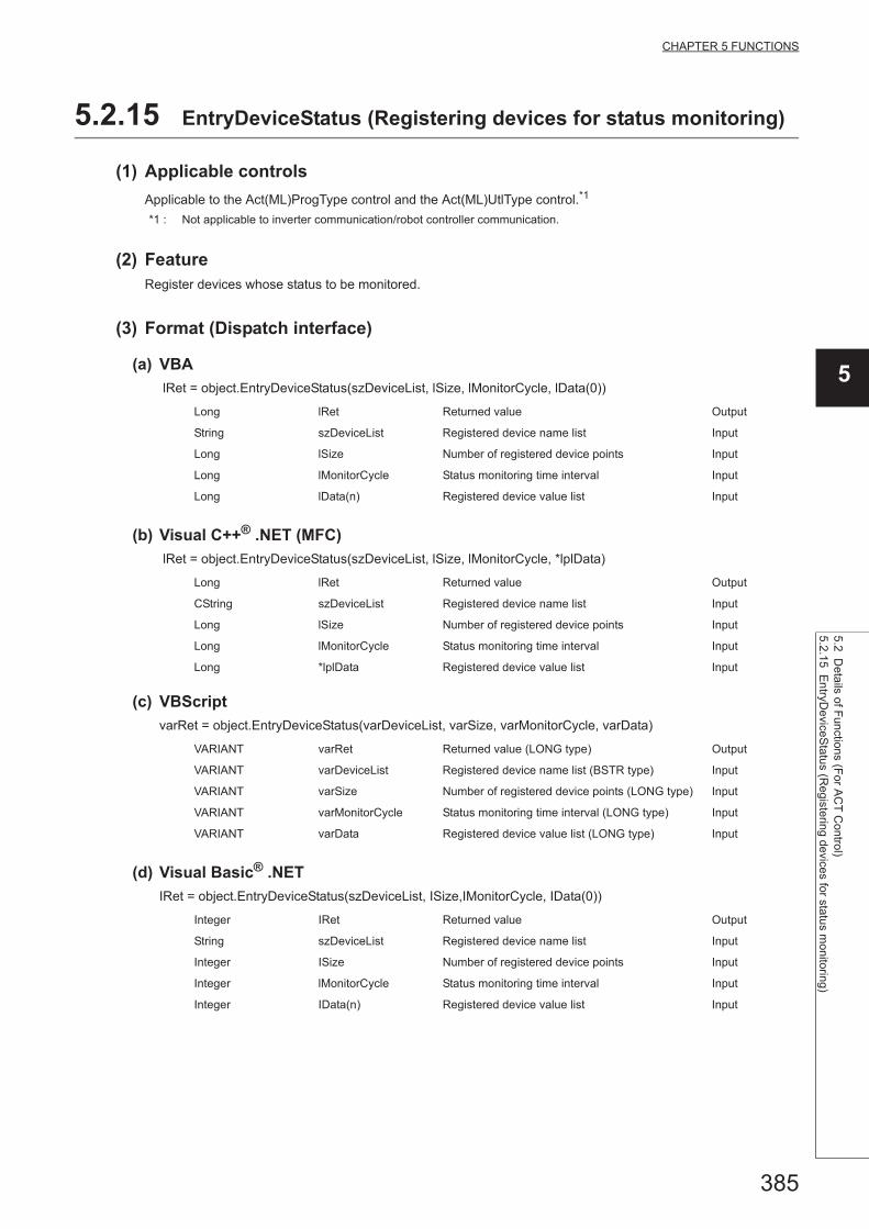
385
CHAPTER 5 FUNCTIONS
5
5.2 Details of F
unctions (For A
CT
Control)
5.2.15 En
tryDeviceS
tatus (Reg
istering devices for status monitoring)
5.2.15 EntryDeviceStatus (Registering devices for status monitoring)
(1) Applicable controls
Applicable to the Act(ML)ProgType control and the Act(ML)UtlType control.*1
*1 : Not applicable to inverter communication/robot controller communication.
(2) FeatureRegister devices whose status to be monitored.
(3) Format (Dispatch interface)
(a) VBA
lRet = object.EntryDeviceStatus(szDeviceList, lSize, lMonitorCycle, lData(0))
(b) Visual C++® .NET (MFC)
lRet = object.EntryDeviceStatus(szDeviceList, lSize, lMonitorCycle, *lplData)
(c) VBScript
varRet = object.EntryDeviceStatus(varDeviceList, varSize, varMonitorCycle, varData)
(d) Visual Basic® .NET
IRet = object.EntryDeviceStatus(szDeviceList, ISize,IMonitorCycle, IData(0))
Long lRet Returned value Output
String szDeviceList Registered device name list Input
Long lSize Number of registered device points Input
Long lMonitorCycle Status monitoring time interval Input
Long lData(n) Registered device value list Input
Long lRet Returned value Output
CString szDeviceList Registered device name list Input
Long lSize Number of registered device points Input
Long lMonitorCycle Status monitoring time interval Input
Long *lplData Registered device value list Input
VARIANT varRet Returned value (LONG type) Output
VARIANT varDeviceList Registered device name list (BSTR type) Input
VARIANT varSize Number of registered device points (LONG type) Input
VARIANT varMonitorCycle Status monitoring time interval (LONG type) Input
VARIANT varData Registered device value list (LONG type) Input
Integer IRet Returned value Output
String szDeviceList Registered device name list Input
Integer ISize Number of registered device points Input
Integer lMonitorCycle Status monitoring time interval Input
Integer IData(n) Registered device value list Input
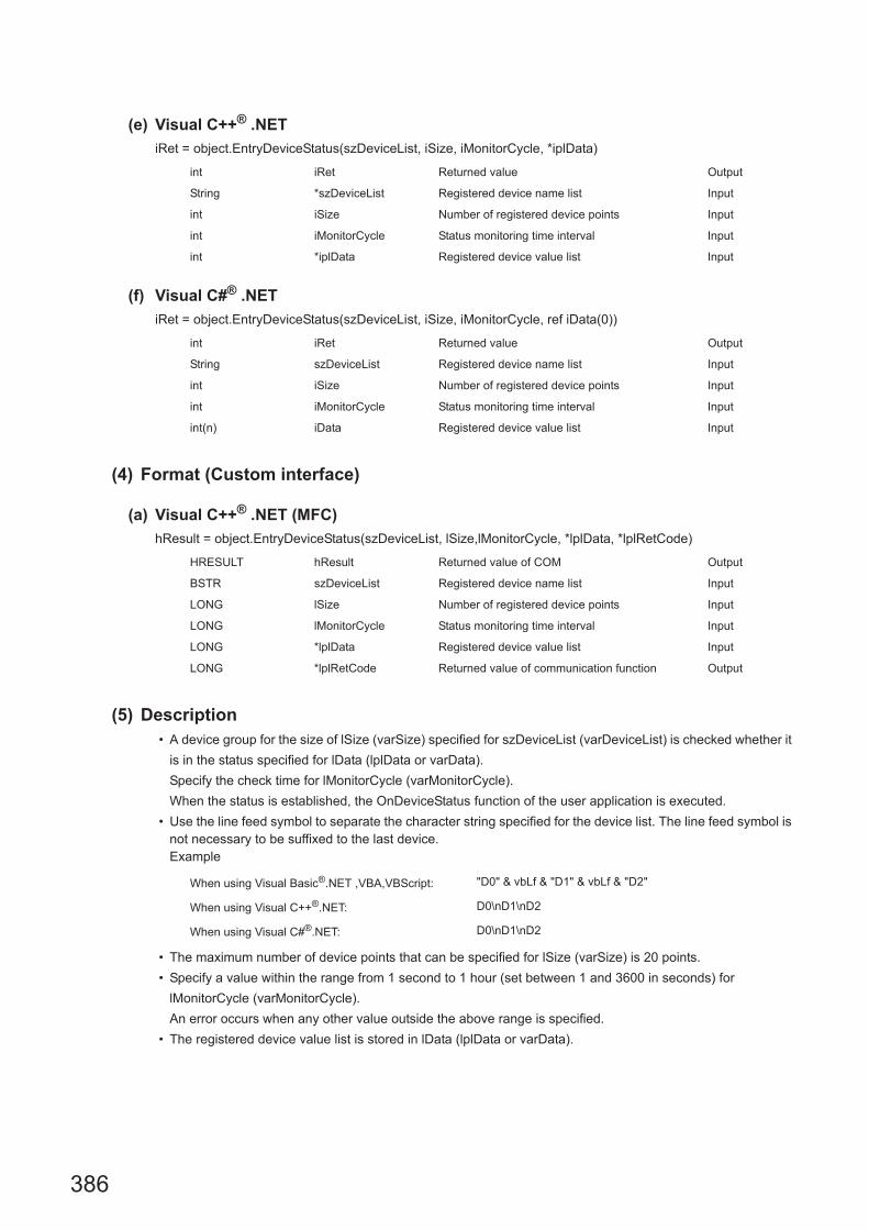
386
(e) Visual C++® .NET
iRet = object.EntryDeviceStatus(szDeviceList, iSize, iMonitorCycle, *iplData)
(f) Visual C#® .NET
iRet = object.EntryDeviceStatus(szDeviceList, iSize, iMonitorCycle, ref iData(0))
(4) Format (Custom interface)
(a) Visual C++® .NET (MFC)
hResult = object.EntryDeviceStatus(szDeviceList, lSize,lMonitorCycle, *lplData, *lplRetCode)
(5) Description • A device group for the size of lSize (varSize) specified for szDeviceList (varDeviceList) is checked whether it
is in the status specified for lData (lplData or varData).
Specify the check time for lMonitorCycle (varMonitorCycle).
When the status is established, the OnDeviceStatus function of the user application is executed.
• Use the line feed symbol to separate the character string specified for the device list. The line feed symbol is not necessary to be suffixed to the last device.Example
• The maximum number of device points that can be specified for lSize (varSize) is 20 points.
• Specify a value within the range from 1 second to 1 hour (set between 1 and 3600 in seconds) for
lMonitorCycle (varMonitorCycle).
An error occurs when any other value outside the above range is specified.
• The registered device value list is stored in lData (lplData or varData).
int iRet Returned value Output
String *szDeviceList Registered device name list Input
int iSize Number of registered device points Input
int iMonitorCycle Status monitoring time interval Input
int *iplData Registered device value list Input
int iRet Returned value Output
String szDeviceList Registered device name list Input
int iSize Number of registered device points Input
int iMonitorCycle Status monitoring time interval Input
int(n) iData Registered device value list Input
HRESULT hResult Returned value of COM Output
BSTR szDeviceList Registered device name list Input
LONG lSize Number of registered device points Input
LONG lMonitorCycle Status monitoring time interval Input
LONG *lplData Registered device value list Input
LONG *lplRetCode Returned value of communication function Output
When using Visual Basic®.NET ,VBA,VBScript: "D0" & vbLf & "D1" & vbLf & "D2"
When using Visual C++®.NET: D0\nD1\nD2
When using Visual C#®.NET: D0\nD1\nD2

387
CHAPTER 5 FUNCTIONS
5
5.2 Details of F
unctions (For A
CT
Control)
5.2.15 En
tryDeviceS
tatus (Reg
istering devices for status monitoring)
(6) How to specify devicesThe following describes how to specify devices.
Example 1: When devices are specified as follows (Number of points: 3 points)
Example 2: When double word devices are specified
Example 3: When devices including FXCPU devices of CN200 and later are specified (Total number of points: 3
points)*2
Example 4: When devices including FD are specified (Total number of points: 3 points)
*1 : Devices are stored from the lower bit in the order of device number.*2 : For CN200 or later of FXCPU, 2 words are read for each point when reading devices randomly.
When using Visual Basic®.NET ,VBA,VBScript: "M0" & vbLf & "D0" & vbLf & "K8M0"
When using Visual C++®.NET: M0\nD0\nK8M0
When using Visual C#®.NET: M0\nD0\nK8M0
Upper 2 bytes Lower 2 bytes
Not used
(0 is stored.)
M0
D0
M16 to M31*1 M0 to M15*1
When using Visual Basic®.NET ,VBA,VBScript: "LTN0" & vbLf & "LTN1" & vbLf & "LTN2"
When using Visual C++®.NET: LTN0\nLTN1\nLTN2
When using Visual C#®.NET: LTN0\nLTN1\nLTN2
Upper 2 bytes Lower 2 bytes
H of LTN0 L of LTN0
H of LTN1 L of LTN1
H of LTN2 L of LTN2
When using Visual Basic®.NET ,VBA,VBScript: "D0" & vbLf & "CN200" & vbLf & "D1"
When using Visual C++®.NET: D0\nCN200\nD1
When using Visual C#®.NET: D0\nCN200\nD1
Upper 2 bytes Lower 2 bytes
Not used
(0 is stored.)D0
H of CN200 L of CN200
Not used
(0 is stored.)D1
When using Visual Basic®.NET ,VBA,VBScript: "D0" & vbLf & "FD0" & vbLf & "D1"
When using Visual C++®.NET: D0\nFD0\nD1
When using Visual C#®.NET: D0\nFD0\nD1
Upper 2 bytes Lower 2 bytes
Not used
(0 is stored.)
D0
LL of FD0
D1

388
Example 5: When 8-bit devices including EG are specified (Total number of points: 3 points)
The following is the example when 8-bit devices (E0000 and E0001 of SHARP programmable
controller) are assigned to EG0.
(7) Returned valueNormal termination : 0 is returned.
Abnormal termination: Any value other than 0 is returned. (Page 516, CHAPTER 7 ERROR CODES)
(8) Considerations for checking word device statusWhen checking the word device status for negative values of -1 to -32768 (FFFFH to 8000H), set the monitor
device value of the EntryDeviceStatus function to any of 65535 to 32768 (0000FFFFH to 00008000H) where "0" is
stored in the upper 2 bytes.
Example: When checking the D0 status for "-10"
Set the value "65526 (0000FFF6H)" where "0" is stored in the upper 2 bytes of "-10 (FFFFFFF6H)" for
the monitor device value.
While the type of word devices of the programmable controller CPU is WORD type, the type of monitor device
value of the EntryDeviceStatus function is LONG type. Therefore, when current values of programmable
controller CPU are compared with monitor device values of the EntryDeviceStatus function, the values do not
match and the above setting is required. (When bit devices or double word devices are used, this consideration
does not apply.)
For the programming examples regarding this consideration, refer to the following section.
Page 554, Appendix 3 Time-Out Periods
When using Visual Basic®.NET ,VBA,VBScript: "D0" & vbLf & "EG0" & vbLf & "D1"
When using Visual C++®.NET: D0\nEG0\nD1
When using Visual C#®.NET: D0\nEG0\nD1
Upper 2 bytes Lower 2 bytes
Not used
(0 is stored.)
D0
EG0
(E0001) (E0000)
D1
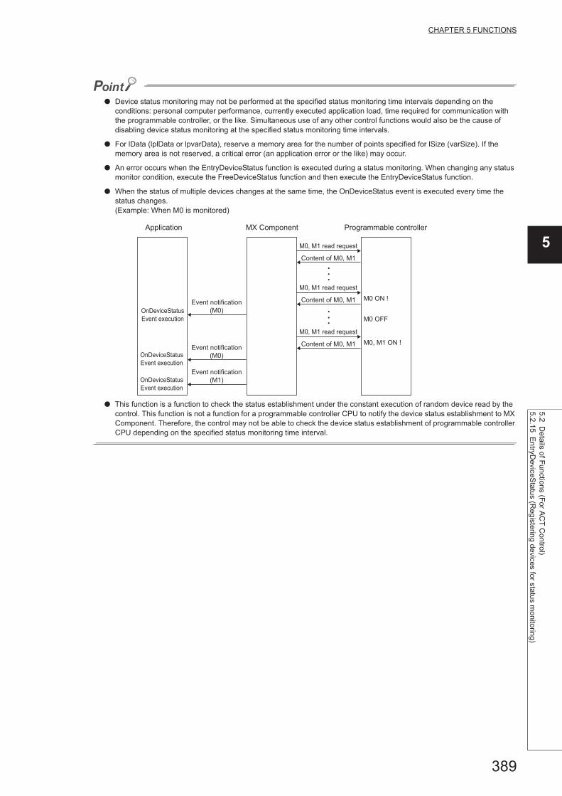
389
CHAPTER 5 FUNCTIONS
5
5.2 Details of F
unctions (For A
CT
Control)
5.2.15 En
tryDeviceS
tatus (Reg
istering devices for status monitoring)
● Device status monitoring may not be performed at the specified status monitoring time intervals depending on the conditions: personal computer performance, currently executed application load, time required for communication with the programmable controller, or the like. Simultaneous use of any other control functions would also be the cause of disabling device status monitoring at the specified status monitoring time intervals.
● For lData (lplData or lpvarData), reserve a memory area for the number of points specified for lSize (varSize). If the memory area is not reserved, a critical error (an application error or the like) may occur.
● An error occurs when the EntryDeviceStatus function is executed during a status monitoring. When changing any status monitor condition, execute the FreeDeviceStatus function and then execute the EntryDeviceStatus function.
● When the status of multiple devices changes at the same time, the OnDeviceStatus event is executed every time the status changes.(Example: When M0 is monitored)
● This function is a function to check the status establishment under the constant execution of random device read by the control. This function is not a function for a programmable controller CPU to notify the device status establishment to MX Component. Therefore, the control may not be able to check the device status establishment of programmable controller CPU depending on the specified status monitoring time interval.
Application MX Component Programmable controller
OnDeviceStatus
Event execution
OnDeviceStatus
Event execution
OnDeviceStatus
Event execution
Event notification
(M0)
Event notification
(M0)
Event notification
(M1)
M0, M1 read request
Content of M0, M1
M0, M1 read request
Content of M0, M1
M0, M1 read request
Content of M0, M1
M0 ON !
M0 OFF
M0, M1 ON !

390
5.2.16 FreeDeviceStatus (Deregistering devices for status monitoring)
(1) Applicable controls
Applicable to the Act(ML)ProgType control and the Act(ML)UtlType control.*1
*1 : Not applicable to inverter communication/robot controller communication.
(2) FeatureDeregister devices that are registered using the EntryDeviceStatus function to monitor their status.
(3) Format (Dispatch interface)
(a) Visual C++® .NET (MFC), VBA
lRet = object.FreeDeviceStatus()
(b) VBScript
varRet = object.FreeDeviceStatus()
(c) Visual Basic® .NET
IRet = object.FreeDeviceStatus()
(d) Visual C++® .NET
iRet = object.FreeDeviceStatus()
(e) Visual C#® .NET
iRet = object.FreeDeviceStatus()
(4) Format (Custom interface)
(a) Visual C++® .NET (MFC)
hResult = object.FreeDeviceStatus( *lplRetCode )
(5) DescriptionThe devices that are set using the EntryDeviceStatus function to monitor their status are deregistered.
(6) Returned valueNormal termination : 0 is returned.
Abnormal termination: Any value other than 0 is returned. (Page 516, CHAPTER 7 ERROR CODES)
Long lRet Returned value Output
VARIANT varRet Returned value (LONG type) Output
Integer IRet Returned value Output
int iRet Returned value Output
int iRet Returned value Output
HRESULT hResult Returned value of COM Output
LONG *lplRetCodeReturned value of
communication functionOutput

391
CHAPTER 5 FUNCTIONS
5
5.2 Details of F
unctions (For A
CT
Control)
5.2.17 OnD
eviceS
tatus (Even
t notification)
5.2.17 OnDeviceStatus (Event notification)
(1) Applicable controls
Applicable to the Act(ML)ProgType control and the Act(ML)UtlType control.*1
*1 : Not applicable to inverter communication/robot controller communication.
(2) FeatureExecute the event notification when the device condition registered using the EntryDeviceStatus function is
satisfied.
(3) Format (Dispatch interface)
(a) VBA
object.OnDeviceStatus(szDevice, lData, lReturnCode)
(b) Visual C++® .NET (MFC)
object.OnDeviceStatus(*szDevice, lData, lReturnCode)
(c) VBScript
object.OnDeviceStatus(varDevice, varData, varReturnCode)
(d) Visual Basic® .NET
Private Sub object_OnDeviceStatus(ByVal sender As System.Object, ByVal e As
objectLib. _objectIEvents_OnDeviceStatusEvent)
String szDevice Name of device whose condition is satisfied Input
Long lData Name of device whose condition is satisfied Input
Long lReturnCode Returned value of condition check processing Input
LPCTSTR *szDevice Name of device whose condition is satisfied Input
Long lData Name of device whose condition is satisfied Input
Long lReturnCode Returned value of condition check processing Input
VARIANT varDeviceName of device whose condition is satisfied
(BSTR type)Input
VARIANT varDataName of device whose condition is satisfied
(LONG type)Input
VARIANT varReturnCodeReturned value of condition check processing
(LONG type)Input
sender Event occurrence source Output
e Event data Output
The following are the members of e.
e.szDevice Name of device whose condition is satisfied
e.lReturnCode Value of device whose condition is satisfied
e.lData Returned value of condition check processing

392
(e) Visual C++® .NET
private: System::Void object_OnDeviceStatus (System::Object * sender,
objectLib. ::_objectIEvents_OnDeviceStatusEvent * e)
(f) Visual C#® .NET
private void object_OnDeviceStatus
(object sender,object._IActUtlTypeEvents_OnDeviceStatusEvent e)
(4) Format (Custom interface)
(a) Visual C++® .NET (MFC)
object.OnDeviceStatus(szDevice, lData, lReturnCode, *lplRetCode)
(5) Description • The event is notified to the application when the device condition registered using the EntryDeviceStatus
function is satisfied.
Programming this function in the user application allows the application to receive the event when the
registered device condition is satisfied.
• Device values registered using the EntryDeviceStatus function are input to lData (varData).
Example: When the word device is monitored for the value of "-1"
Set 65535 (0000FFFFH) as a registered device value using the EntryDeviceStatus function.
When the value of the target word device of the programmable controller CPU becomes
"-1" (FFFFH), the OnDeviceStatus function is executed and (0000FFFFH) is input to lData (varData).
sender Event occurrence source Output
e Event data Output
The following are the members of e.
e->szDevice Name of device whose condition is satisfied
e->lReturnCode Value of device whose condition is satisfied
e->lData Returned value of condition check processing
sender Event occurrence source Output
e Event data Output
The following are the members of e.
e->szDevice Name of device whose condition is satisfied
e->lReturnCode Returned value of condition check processing
e->lData Value of device whose condition is satisfied
LPCTSTR szDevice Name of device whose condition is satisfied Input
LONG lData Name of device whose condition is satisfied Input
LONG lReturnCode Returned value of condition check processing Input
LONG *lplRetCode Returned value of communication function Output

393
CHAPTER 5 FUNCTIONS
5
5.2 Details of F
unctions (For A
CT
Control)
5.2.17 OnD
eviceS
tatus (Even
t notification)
(6) Returned valueNone
● When any of the following settings is set in the user application, the event of the OnDeviceStatus function does not occur even if the condition of the device registered to the EntryDeviceStatus function is satisfied. Note that when the event occurrence becomes in wait status, the control function is not returned to the control and device management processing stops until the following setting is terminated.
• User applications created using Visual Basic® or VBA (Excel)The message box is displayed in the user application.The InputBox/OutputBox is displayed in the user application.
• User applications created using Visual Basic® , Visual C++® , Visual C#® , VBA (Excel, Access) or VBScriptThe Sleep processing, WaitForSingleObject function, or similar standby function is used in the user application.
● For installing Reference, refer to the sample programs for Reference for VB .NET/VC .NET. (Page 500, Section 6.4, Page 507, Section 6.5)

394
5.2.18 ReadDeviceBlock2 (Reading devices in bulk)
(1) Applicable controls
Applicable to the Act(ML)ProgType control and the Act(ML)UtlType control.*1
*1 : Not applicable to inverter communication/robot controller communication.
(2) FeatureRead devices in 2-byte data unit in bulk.
(3) Format (Dispatch interface)
(a) VBA
lRet = object.ReadDeviceBlock2(szDevice, lSize, iData(0))
(b) Visual C++® .NET (MFC)
lRet = object.ReadDeviceBlock2(szDevice, lSize, *lpsData)
(c) VBScript
varRet = object.ReadDeviceBlock2(varDevice, varSize, lpvarData)
(d) Visual Basic® .NET
IRet = object.ReadDeviceBlock2(szDevice, ISize, sData(0))
(e) Visual C++® .NET
iRet = object.ReadDeviceBlock2(*szDevice, iSize, *lpsData)
Long lRet Returned value Output
String szDevice Device name Input
Long lSize Number of read points Input
Integer iData(n) Read device value Output
Long lRet Returned value Output
CString szDevice Device name Input
Long lSize Number of read points Input
Short *lpsData Read device value Output
VARIANT varRet Returned value (LONG type) Output
VARIANT varDevice Device name (character string type) Input
VARIANT varSize Number of read points (LONG type) Input
VARIANT lpvarData Read device value (SHORT type) Output
Integer IRet Returned value Output
String szDevice Device name Input
Integer ISize Number of read points Input
short sData(n) Read device value Output
int iRet Returned value Output
String *szDevice Device name Input
int iSize Number of read points Input
short *lpsData Read device value Output
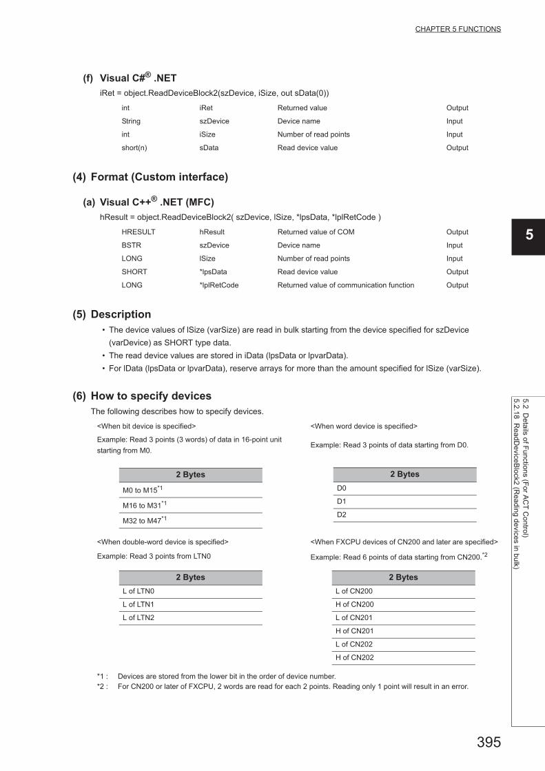
395
CHAPTER 5 FUNCTIONS
5
5.2 Details of F
unctions (For A
CT
Control)
5.2.18 ReadD
eviceBlock2 (R
eading devices in bulk)
(f) Visual C#® .NET
iRet = object.ReadDeviceBlock2(szDevice, iSize, out sData(0))
(4) Format (Custom interface)
(a) Visual C++® .NET (MFC)
hResult = object.ReadDeviceBlock2( szDevice, lSize, *lpsData, *lplRetCode )
(5) Description • The device values of lSize (varSize) are read in bulk starting from the device specified for szDevice
(varDevice) as SHORT type data.
• The read device values are stored in iData (lpsData or lpvarData).
• For lData (lpsData or lpvarData), reserve arrays for more than the amount specified for lSize (varSize).
(6) How to specify devicesThe following describes how to specify devices.
int iRet Returned value Output
String szDevice Device name Input
int iSize Number of read points Input
short(n) sData Read device value Output
HRESULT hResult Returned value of COM Output
BSTR szDevice Device name Input
LONG lSize Number of read points Input
SHORT *lpsData Read device value Output
LONG *lplRetCode Returned value of communication function Output
<When bit device is specified> <When word device is specified>
Example: Read 3 points (3 words) of data in 16-point unit
starting from M0.Example: Read 3 points of data starting from D0.
<When double-word device is specified> <When FXCPU devices of CN200 and later are specified>
Example: Read 3 points from LTN0 Example: Read 6 points of data starting from CN200.*2
*1 : Devices are stored from the lower bit in the order of device number.*2 : For CN200 or later of FXCPU, 2 words are read for each 2 points. Reading only 1 point will result in an error.
2 Bytes
M0 to M15*1
M16 to M31*1
M32 to M47*1
2 Bytes
D0
D1
D2
2 Bytes
L of LTN0
L of LTN1
L of LTN2
2 Bytes
L of CN200
H of CN200
L of CN201
H of CN201
L of CN202
H of CN202

396
(7) Returned valueNormal termination : 0 is returned.
Abnormal termination: Any value other than 0 is returned. (Page 516, CHAPTER 7 ERROR CODES)
● The maximum number of read points that can be specified for lSize (varSize) should be the value which satisfies the following condition.Read starting device number + Number of read points Last device number
● When specifying bit devices, a multiple of 16 can be specified as a device number.
● For iData (lpsData or lpvarData), reserve a memory area for the number of points specified for lSize (varSize).If the memory area is not reserved, a critical error (an application error or the like) may occur.
<When FD device is specified (4-word device)>
Example: Read 6 points of data starting from FD0.
<8-bit devices assigned to gateway devices>
Example: Read 4 points of data starting from EG0.
(When 8-bit devices (from E0000 to E0007 of SHARP programmable controller) are assigned from EG0 to EG3.)
2 Bytes
LL of FD0
LH of FD0
HL of FD0
HH of FD0
LL of FD1
LH of FD1
2 Bytes
EG0
(E0001) (E0000)
EG1
(E0003) (E0002)
EG2
(E0005) (E0004)
EG3
(E0007) (E0006)

397
CHAPTER 5 FUNCTIONS
5
5.2 Details of F
unctions (For A
CT
Control)
5.2.19 WriteD
eviceBlock2 (W
riting devices in bulk)
5.2.19 WriteDeviceBlock2 (Writing devices in bulk)
(1) Applicable controls
Applicable to the Act(ML)ProgType control and the Act(ML)UtlType control.*1
*1 : Not applicable to inverter communication/robot controller communication.
(2) FeatureWrite devices in 2-byte data unit in bulk.
(3) Format (Dispatch interface)
(a) VBA
lRet = object.WriteDeviceBlock2(szDevice, lSize, iData(0))
(b) Visual C++® .NET (MFC)
lRet = object.WriteDeviceBlock2(szDevice, lSize, *lpsData)
(c) VBScript
varRet = object.WriteDeviceBlock2(varDevice, varSize, varData)
(d) Visual Basic® .NET
IRet = object.WriteDeviceBlock2(szDevice,ISize, sData(0))
(e) Visual C++® .NET
iRet = object.WriteDeviceBlock2(*szDevice, iSize, *lpsData)
Long lRet Returned value Output
String szDevice Device name Input
Long lSize Number of write points Input
Integer iData(n) Device value to be written Input
Long lRet Returned value Output
CString szDevice Device name Input
Long lSize Number of write points Input
Short *lpsData Device value to be written Input
VARIANT varRet Returned value (LONG type) Output
VARIANT varDevice Device name (character string type) Input
VARIANT varSize Number of write points (LONG type) Input
VARIANT varData Device value to be written (SHORT type) Input
Integer IRet Returned value Output
String szDevice Device name Input
Integer ISize Number of write points Input
short sData(n) Device value to be written Input
int iRet Returned value Output
String *szDevice Device name Input
int iSize Number of write points Input
short *lpsData Device value to be written Input

398
(f) Visual C#® .NET
iRet = object.WriteDeviceBlock2(szDevice, iSize, ref sData(0))
(4) Format (Custom interface)
(a) Visual C++® .NET (MFC)
hResult = object.WriteDeviceBlock2(szDevice, lSize, *lpsData, *lplRetCode )
(5) Description • The device values of lSize (varSize) are written in bulk starting from the device specified for szDevice
(varDevice).
• The device values to be written are stored in lData (lplData or varData).
• For lData (lpsData or varData), reserve arrays for more than the amount specified for lSize (varSize).
(6) How to specify devicesThe following describes how to specify devices.
int iRet Returned value Output
String szDevice Device name Input
int iSize Number of write points Input
short(n) sData Device value to be written Input
HRESULT hResult Returned value of COM Output
BSTR szDevice Device name Input
LONG lSize Number of write points Input
SHORT *lpsData Device value to be written Input
LONG *lplRetCode Returned value of communication function Output
<When bit device is specified> <When word device is specified>
Example: Write 3 points (3 words) of data in 16-point unit
starting from M0.Example: Write 3 points of data starting from D0.
<When double-word device is specified> <When FXCPU devices of CN200 and later are specified>
Example: Write 3 points to LTN0 Example: Write 6 points of data starting from CN200.*2
*1 : Devices are stored from the lower bit in the order of device number.*2 : For CN200 or later of FXCPU, 2 words are written for each 2 points. Writing only 1 point will result in an error.
2 bytes
M0 to M15*1
M16 to M31*1
M32 to M47*1
2 bytes
D0
D1
D2
2 bytes
L of LTN0
L of LTN1
L of LTN2
2 bytes
L of CN200
H of CN200
L of CN201
H of CN201
L of CN202
H of CN202

399
CHAPTER 5 FUNCTIONS
5
5.2 Details of F
unctions (For A
CT
Control)
5.2.19 WriteD
eviceBlock2 (W
riting devices in bulk)
(7) Returned valueNormal termination : 0 is returned.
Abnormal termination: Any value other than 0 is returned. (Page 516, CHAPTER 7 ERROR CODES)
● The maximum number of write points that can be specified for lSize (varSize) should be the value which satisfies the following condition.Write starting device number + Number of write points Last device number
● When specifying bit devices, a multiple of 16 can be specified as a device number.
● For iData (lpsData or varData), reserve a memory area for the number of points specified for lSize (varSize).If the memory area is not reserved, a critical error (an application error or the like) may occur.
● WriteDeviceBlock2 cannot be used for writing long timer device (LT) and retentive long timer device (LST).Use WriteDeviceRandom2 or SetDevice2.
<When FD device is specified (4-word device)>
Example: Write 6 points of data starting from FD0.
<8-bit devices assigned to gateway devices>
Example: Write 4 points of data starting from EG0.
(When 8-bit devices (from E0000 to E0007 of SHARP programmable controller) are assigned from EG0 to EG3.)
2 bytes
LL of FD0
LH of FD0
HL of FD0
HH of FD0
LL of FD1
LH of FD1
2 bytes
EG0
(E0001) (E0000)
EG1
(E0003) (E0002)
EG2
(E0005) (E0004)
EG3
(E0007) (E0006)

400
5.2.20 ReadDeviceRandom2 (Reading devices randomly)
(1) Applicable controls
Applicable to the Act(ML)ProgType control and the Act(ML)UtlType control.*1
*1 : Not applicable to inverter communication/robot controller communication.
(2) FeatureRead devices in 2-byte data unit randomly.
(3) Format (Dispatch interface)
(a) VBA
lRet = object.ReadDeviceRandom2(szDeviceList, lSize, iData(0))
(b) Visual C++® .NET (MFC)
lRet = object.ReadDeviceRandom2(szDeviceList, lSize, *lpsData)
(c) VBScript
varRet = object.ReadDeviceRandom2(varDeviceList, varSize, lpvarData)
(d) Visual Basic® .NET
IRet = object.ReadDeviceRandom2(szDeviceList, ISize, sData(0))
(e) Visual C++® .NET
iRet = object.ReadDeviceRandom(*szDeviceList, iSize, *lpsData)
Long lRet Returned value Output
String szDeviceList Device name Input
Long lSize Number of read points Input
Integer iData(n) Read device value Output
Long lRet Returned value Output
CString szDeviceList Device name Input
Long lSize Number of read points Input
Short *lpsData Read device value Output
VARIANT varRet Returned value (LONG type) Output
VARIANT varDeviceList Device name (character string type) Input
VARIANT varSize Number of read points (LONG type) Input
VARIANT lpvarData Read device value (SHORT type) Output
Integer IRet Returned value Output
String szDeviceList Device name Input
Integer ISize Number of read points Input
short sData(n) Read device value Output
int iRet Returned value Output
String *szDeviceList Device name Input
int iSize Number of read points Input
short *lpsData Read device value Output

401
CHAPTER 5 FUNCTIONS
5
5.2 Details of F
unctions (For A
CT
Control)
5.2.20 ReadD
eviceRandom
2 (Reading devices random
ly)
(f) Visual C#® .NET
iRet = object.ReadDeviceRandom(szDevice, iSize, out sData(0))
(4) Format (Custom interface)
(a) Visual C++® .NET (MFC)
hResult = object.ReadDeviceRandom2( szDeviceList, lSize, *lpsData, *lplRetCode )
(5) Description • Data of a device group for the size of lSize (varSize) specified for szDeviceList (varDeviceList) are read.
• The read device values are stored in iData (lpsData or lpvarData).
• Use the line feed symbol to separate the character string specified for the device list. The line feed symbol is
not necessary to be suffixed to the last device.
Example:
• For lData (lpsData or lpvarData), reserve arrays for more than the amount specified for lSize (varSize).
(6) How to specify devicesThe following describes how to specify devices.
Example 1: When devices are specified as follows (Number of points: 3 points)
*1 : The target device from which data is read is only one point of "M0", and "0" or "1" is stored as the device value.*2 : Devices are stored from the lower bit in the order of device number.
Data are not read from the upper 2 bytes of M16 to M31.
int iRet Returned value Output
String szDevice Device name Input
int iSize Number of read points Input
short(n) sData Read device value Output
HRESULT hResult Returned value of COM Output
BSTR szDeviceList Device name Input
LONG lSize Number of read points Input
SHORT *lpsData Read device value Output
LONG *lplRetCode Returned value of communication function Output
When using Visual Basic®.NET ,VBA,VBScript: "D0" & vbLf & "D1" & vbLf & "D2"
When using Visual C++®.NET: D0\nD1\nD2
When using Visual C#®.NET: D0\nD1\nD2
When using Visual Basic®.NET ,VBA,VBScript: "M0" & vbLf & "D0" & vbLf & "K8M0"
When using Visual C++®.NET: M0\nD0\nK8M0
When using Visual C#®.NET: M0\nD0\nK8M0
2 Bytes
M0*1
D0
M0 to M15*2

402
Example 2: When double word devices are specified
Example 3: When devices including FXCPU devices of CN200 and later are specified (Total number of points: 3
points)*3
*3 : For FXCPU devices of CN200 and later, the L (lower 2 bytes) of the specified devices is read for each point when the ReadDeviceRandom2 function is executed.The H (upper 2 bytes) of the specified devices is not read.
Example 4: When devices including FD are specified (Total number of points: 3 points)
Example 5: When 8-bit devices including EG are specified (Total number of points: 3 points)
The following is the example when 8-bit devices (E0000 and E0001 of SHARP programmable
controller) are assigned to EG0.
When using Visual Basic®.NET ,VBA,VBScript: "LTN0" & vbLf & "LTN1" & vbLf & "LTN2"
When using Visual C++®.NET: LTN0\nLTN1\nLTN2
When using Visual C#®.NET: LTN0\nLTN1\nLTN2
2 Bytes
L of LTN0
L of LTN1
L of LTN2
When using Visual Basic®.NET ,VBA,VBScript: "D0" & vbLf & "CN200" & vbLf & "D1"
When usingVisual C++®.NET: D0\nCN200\nD1
When using Visual C#®.NET: D0\nCN200\nD1
2 Bytes
D0
L of CN200*3
D1
When using Visual Basic®.NET ,VBA,VBScript: "D0" & vbLf & "FD0" & vbLf & "D1"
When using Visual C++®.NET: D0\nFD0\nD1
When using Visual C#®.NET: D0\nFD0\nD1
2 Bytes
D0
LL of FD0
D1
When using Visual Basic®.NET ,VBA,VBScript: "D0" & vbLf & "EG0" & vbLf & "D1"
When using Visual C++®.NET: D0\nEG0\nD1
When using Visual C#®.NET: D0\nEG0\nD1
2 Bytes
D0
EG0
(E0001) (E0000)
D1

403
CHAPTER 5 FUNCTIONS
5
5.2 Details of F
unctions (For A
CT
Control)
5.2.20 ReadD
eviceRandom
2 (Reading devices random
ly)
(7) Returned valueNormal termination : 0 is returned.
Abnormal termination: Any value other than 0 is returned. (Page 516, CHAPTER 7 ERROR CODES)
● The maximum number of read points that can be specified for lSize (varSize) is 0x7FFFFFFF points.
● For iData (lpsData or lpvarData), reserve a memory area for the number of points specified for lSize (varSize).If the memory area is not reserved, a critical error (an application error or the like) may occur.
● When a double word device is specified, only the data of the lower 1 word (2 bytes) are stored using the ReadDeviceRandom2 function. (An error does not occur.)When reading data from a double word device, use the ReadDeviceRandom function or the GetDevice function.

404
5.2.21 WriteDeviceRandom2 (Writing devices randomly)
(1) Applicable controls
Applicable to the Act(ML)ProgType control and the Act(ML)UtlType control.*1
*1 : Not applicable to inverter communication/robot controller communication.
(2) FeatureWrite devices in 2-byte data unit randomly.
(3) Format (Dispatch interface)
(a) VBA
lRet = object.WriteDeviceRandom2(szDeviceList, lSize, iData(0))
(b) Visual C++® .NET (MFC)
lRet = object.WriteDeviceRandom2(szDeviceList, lSize, *lpsData)
(c) VBScript
varRet = object.WriteDeviceRandom2(varDeviceList, varSize, varData)
(d) Visual Basic® .NET
IRet = object.WriteDeviceRandom2(szDeviceList, ISize, sData(0))
(e) Visual C++® .NET
iRet = object.WriteDeviceRandom2(*szDeviceList, iSize, *ipsData)
Long lRet Returned value Output
String szDeviceList Device name Input
Long lSize Number of write points Input
Integer iData(n) Device value to be written Input
Long lRet Returned value Output
CString szDeviceList Device name Input
Long lSize Number of write points Input
Short *lpsData Device value to be written Input
VARIANT varRet Returned value (LONG type) Output
VARIANT varDeviceList Device name (character string type) Input
VARIANT varSize Number of write points (LONG type) Input
VARIANT varData Device value to be written (SHORT type) Input
Integer IRet Returned value Output
String szDeviceList Device name Input
Integer ISize Number of write points Input
short sData(n) Device value to be written Input
int iRet Returned value Output
String *szDeviceList Device name Input
int iSize Number of write points Input
short *ipsData Device value to be written Input

405
CHAPTER 5 FUNCTIONS
5
5.2 Details of F
unctions (For A
CT
Control)
5.2.21 WriteD
eviceRandom
2 (Writing d
evices randomly)
(f) Visual C#® .NET
iRet = object.WriteDeviceRandom2(szDevice, iSize, ref sData(0))
(4) Format (Custom interface)
(a) Visual C++® .NET (MFC)
hResult = object.WriteDeviceRandom2( szDeviceList, lSize, *lpsData, *lplRetCode )
(5) Description • Data of a device group for the size of lSize (varSize) specified for szDeviceList (varDeviceList) are written.
• The device values to be written are stored in iData (lpsData or varData).
• Use the line feed symbol to separate the character string specified for the device list. The line feed symbol is
not necessary to be suffixed to the last device.
Example:
• For lData (lpsData or varData), reserve arrays for more than the amount specified for lSize (varSize).
(6) How to specify devicesThe following describes how to specify devices.
Example 1: When devices are specified as follows (Number of points: 3 points)
*1 : The target device to which data is written is only one point of "M0", and the least significant bit of the set 2-byte data is written as the device value.
*2 : Devices are stored from the lower bit in the order of device number. "0" is written to the upper 2 bytes of M16 to M31.
int iRet Returned value Output
String szDevice Device name Input
int iSize Number of write points Input
short(n) sData Device value to be written Input
HRESULT hResult Returned value of COM Output
BSTR szDeviceList Device name Input
LONG lSize Number of write points Input
SHORT *lpsData Device value to be written Input
LONG *lplRetCode Returned value of communication function Output
When using Visual Basic®.NET ,VBA,VBScript: "D0" & vbLf & "D1" & vbLf & "D2"
When using Visual C++®.NET: D0\nD1\nD2
When using Visual C#®.NET: D0\nD1\nD2
When using Visual Basic®.NET ,VBA,VBScript: "M0" & vbLf & "D0" & vbLf & "K8M0"
When using Visual C++®.NET: M0\nD0\nK8M0
When using Visual C#®.NET: M0\nD0\nK8M0
2 Bytes
M0*1
D0
M0 to M15*2

406
Example 2: When double word devices are specified
Example 3: When devices including FXCPU devices of CN200 and later are specified (Total number of points: 3
points)*3
*3 : For FXCPU devices of CN200 and later, data are written to the L (lower 2 bytes) of the specified devices for each point when the WriteDeviceRandom2 function is executed. "0" is written to the H (upper 2 bytes) of the specified devices.
Example 4: When devices including FD are specified (Total number of points: 3 points)
Example 5: When 8-bit devices including EG are specified (Total number of points: 3 points)
The following is the example when 8-bit devices (E0000 and E0001 of SHARP programmable
controller) are assigned to EG0.
When using Visual Basic®.NET ,VBA,VBScript: "LTN0" & vbLf & "LTN1" & vbLf & "LTN2"
When using Visual C++®.NET: LTN0\nLTN1\nLTN2
When using Visual C#®.NET: LTN0\nLTN1\nLTN2
2 Bytes
L of LTN0
L of LTN1
L of LTN2
When using Visual Basic®.NET ,VBA,VBScript: "D0" & vbLf & "CN200" & vbLf & "D1"
When using Visual C++®.NET: D0\nCN200\nD1
When using Visual C#®.NET: D0\nCN200\nD1
2 Bytes
D0
L of CN200*3
D1
When using Visual Basic®.NET ,VBA,VBScript: "D0" & vbLf & "FD0" & vbLf & "D1"
When using Visual C++®.NET: D0\nFD0\nD1
When using Visual C#®.NET: D0\nFD0\nD1
2 Bytes
D0
LL of FD0
D1
When using Visual Basic®.NET ,VBA,VBScript: "D0" & vbLf & "EG0" & vbLf & "D1"
When using Visual C++®.NET: D0\nEG0\nD1
When using Visual C#®.NET: D0\nEG0\nD1
2 Bytes
D0
EG0
(E0001) (E0000)
D1

407
CHAPTER 5 FUNCTIONS
5
5.2 Details of F
unctions (For A
CT
Control)
5.2.21 WriteD
eviceRandom
2 (Writing d
evices randomly)
(7) Returned valueNormal termination : 0 is returned.
Abnormal termination: Any value other than 0 is returned. (Page 516, CHAPTER 7 ERROR CODES)
● The maximum number of write points that can be specified for lSize (varSize) is 0x7FFFFFFF points.
● For iData (lpsData or varData), reserve a memory area for the number of points specified for lSize (varSize).If the memory area is not reserved, a critical error (an application error or the like) may occur.
● When a double word device is specified, data are written to the data area of the lower 1 word (2 bytes) using the WriteDeviceRandom2 function, and "0" is written to the data area of the upper 1 word (2 bytes).When writing a double word device, use the WriteDeviceRandom function or the SetDevice function.
● If a Q motion CPU is accessed, an error is returned.
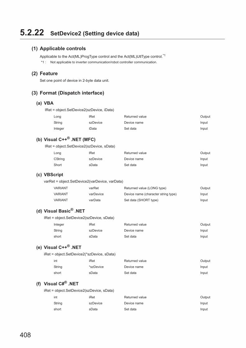
408
5.2.22 SetDevice2 (Setting device data)
(1) Applicable controls
Applicable to the Act(ML)ProgType control and the Act(ML)UtlType control.*1
*1 : Not applicable to inverter communication/robot controller communication.
(2) FeatureSet one point of device in 2-byte data unit.
(3) Format (Dispatch interface)
(a) VBA
lRet = object.SetDevice2(szDevice, iData)
(b) Visual C++® .NET (MFC)
lRet = object.SetDevice2(szDevice, sData)
(c) VBScript
varRet = object.SetDevice2(varDevice, varData)
(d) Visual Basic® .NET
IRet = object.SetDevice2(szDevice, sData)
(e) Visual C++® .NET
iRet = object.SetDevice2(*szDevice, sData)
(f) Visual C#® .NET
iRet = object.SetDevice2(szDevice, sData)
Long lRet Returned value Output
String szDevice Device name Input
Integer iData Set data Input
Long lRet Returned value Output
CString szDevice Device name Input
Short sData Set data Input
VARIANT varRet Returned value (LONG type) Output
VARIANT varDevice Device name (character string type) Input
VARIANT varData Set data (SHORT type) Input
Integer IRet Returned value Output
String szDevice Device name Input
short sData Set data Input
int iRet Returned value Output
String *szDevice Device name Input
short sData Set data Input
int iRet Returned value Output
String szDevice Device name Input
short sData Set data Input

409
CHAPTER 5 FUNCTIONS
5
5.2 Details of F
unctions (For A
CT
Control)
5.2.22 Se
tDevice2 (S
etting device data)
(4) Format (Custom interface)
(a) Visual C++® .NET (MFC)
hResult = object.SetDevice2( szDevice, sData, *lplRetCode )
(5) Description • One point of device specified for szDevice (varDevice) is specified using lData (varData).
• When specifying bit devices, the least significant bit of the iData value (sData value or varData value) is valid.
(6) How to specify devicesThe following describes how to specify devices.
HRESULT hResult Returned value of COM Output
BSTR szDevice Device name Input
SHORT sData Set data Input
LONG *lplRetCode Returned value of communication function Output
<When bit device is specified> <When word device is specified>
Example: M0 Example: D0
<When double-word device is specified> <When double-word device is specified(Digit specification)>
Example: LTN0 Example: K8M0
<When CN200 or later of FXCPU is specified>
Example: CN200
<When gateway device is specified>
Example: When 8-bit devices (E0000 and E0001 of SHARP programmable controller) are assigned to EG0
*1 : The target device to which data is written is only one point of "M0", and the least significant bit of the set 2-byte data is written as the device value.
*2 : Devices are stored from the lower bit in the order of device number."0" is written to the upper 2 bytes of M16 to M31.
*3 : For FXCPU devices of CN200 and later, data are written to the L (lower 2 bytes) of the specified devices for each point when the SetDevice2 function is executed."0" is written to the H (upper 2 bytes) of the specified devices.
2 Bytes
M0*1
2 Bytes
D0
2 Bytes
L of LTN0
2 Bytes
M0 to M15*2
2 Bytes
L of CN200*3
2 Bytes
EG0
(E0001) (E0000)

410
(7) Returned valueNormal termination : 0 is returned.
Abnormal termination: Any value other than 0 is returned. (Page 516, CHAPTER 7 ERROR CODES)
● When a double word device is specified, data are written to the data area of the lower 1 word (2 bytes) using the SetDevice2 function, and "0" is written to the data area of the upper 1 word (2 bytes).When writing a double word device, use the WriteDeviceRandom function or the SetDevice function.

411
CHAPTER 5 FUNCTIONS
5
5.2 Details of F
unctions (For A
CT
Control)
5.2.23 GetD
evice2 (Acquirin
g device data)
5.2.23 GetDevice2 (Acquiring device data)
(1) Applicable controls
Applicable to the Act(ML)ProgType control and the Act(ML)UtlType control.*1
*1 : Not applicable to inverter communication/robot controller communication.
(2) FeatureAcquire one point of device in 2-byte data unit.
(3) Format (Dispatch interface)
(a) VBA
lRet = object.GetDevice2(szDevice, iData)
(b) Visual C++® .NET (MFC)
lRet = object.GetDevice2(szDevice, lSize, *lpsData)
(c) VBScript
varRet = object.GetDevice2(varDevice, lpvarData)
(d) Visual Basic® .NET
IRet = object.GetDevice2(szDevice, sData)
(e) Visual C++® .NET
iRet = object.GetDevice(*szDevice, *ipsData)
(f) Visual C#® .NET
iRet = object.GetDevice2(szDevice, out sData)
Long lRet Returned value Output
String szDevice Device name Input
Integer iData Acquired data Output
Long lRet Returned value Output
CString szDevice Device name Input
Short *lpsData Acquired data Output
VARIANT varRet Returned value (LONG type) Output
VARIANT varDevice Device name (character string type) Input
VARIANT lpvarData Acquired data (SHORT type) Output
Integer IRet Returned value Output
String szDevice Device name Input
short sData Acquired data Output
int iRet Returned value Output
String *szDevice Device name Input
short *spsData Acquired data Output
int iRet Returned value Output
String szDevice Device name Input
short sData Acquired data Output

412
(4) Format (Custom interface)
(a) Visual C++® .NET (MFC)
hResult = object.GetDevice2( szDevice, *lpsData, *lplRetCode )
(5) DescriptionOne point of device data specified for szDevice (varDevice) is stored in iData (lpsData or lpvarData).
(6) How to specify devicesThe following describes how to specify devices.
HRESULT hResult Returned value of COM Output
BSTR szDevice Device name Input
SHORT *lpsData Acquired data Output
LONG *lplRetCode Returned value of communication function Output
<When bit device is specified> <When word device is specified>
Example: M0 Example: D0
<When double-word device is specified> <When double-word device is specified (Digit specification)>
Example: LTN0 Example: K8M0
<When CN200 or later of FXCPU is specified>
Example: CN200
<When gateway device is specified>
Example: When 8-bit devices (E0000 and E0001 of SHARP programmable controller) are assigned to EG0
*1 : The target device from which data is read is only one point of "M0", and "0" or "1" is stored as the device value.*2 : Devices are stored from the lower bit in the order of device number.
Data are not read from the upper 2 bytes of M16 to M31.*3 : For FXCPU devices of CN200 and later, the L (lower 2 bytes) of the specified devices is read for each point when the
GetDevice2 function is executed.The H (upper 2 bytes) of the specified devices is not read.
2 Bytes
M0*1
2 Bytes
D0
2 Bytes
L of LTN0
2 Bytes
M0 to M15*2
2 Bytes
L of CN200*3
2 Bytes
EG0
(E0001) (E0000)

413
CHAPTER 5 FUNCTIONS
5
5.2 Details of F
unctions (For A
CT
Control)
5.2.23 GetD
evice2 (Acquirin
g device data)
(7) Returned valueNormal termination : 0 is returned.
Abnormal termination: Any value other than 0 is returned. (Page 516, CHAPTER 7 ERROR CODES)
● When a double word device is specified, only the data of the lower 1 word (2 bytes) are stored using the GetDevice2 function. (An error does not occur.)
● When reading data from a double word device, use the ReadDeviceRandom function or the GetDevice function.
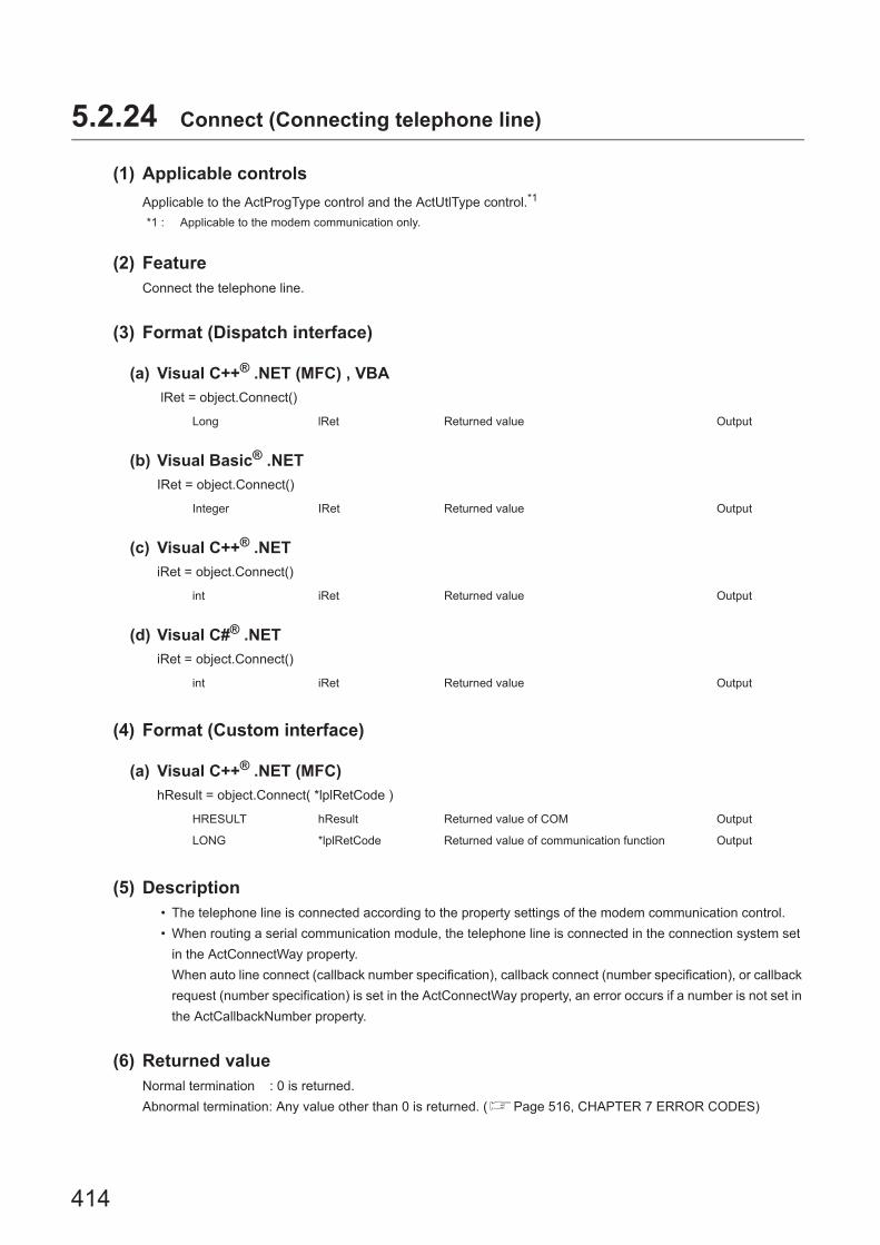
414
5.2.24 Connect (Connecting telephone line)
(1) Applicable controls
Applicable to the ActProgType control and the ActUtlType control.*1
*1 : Applicable to the modem communication only.
(2) FeatureConnect the telephone line.
(3) Format (Dispatch interface)
(a) Visual C++® .NET (MFC) , VBA
lRet = object.Connect()
(b) Visual Basic® .NET
IRet = object.Connect()
(c) Visual C++® .NET
iRet = object.Connect()
(d) Visual C#® .NET
iRet = object.Connect()
(4) Format (Custom interface)
(a) Visual C++® .NET (MFC)
hResult = object.Connect( *lplRetCode )
(5) Description • The telephone line is connected according to the property settings of the modem communication control.
• When routing a serial communication module, the telephone line is connected in the connection system set
in the ActConnectWay property.
When auto line connect (callback number specification), callback connect (number specification), or callback
request (number specification) is set in the ActConnectWay property, an error occurs if a number is not set in
the ActCallbackNumber property.
(6) Returned valueNormal termination : 0 is returned.
Abnormal termination: Any value other than 0 is returned. (Page 516, CHAPTER 7 ERROR CODES)
Long lRet Returned value Output
Integer IRet Returned value Output
int iRet Returned value Output
int iRet Returned value Output
HRESULT hResult Returned value of COM Output
LONG *lplRetCode Returned value of communication function Output

415
CHAPTER 5 FUNCTIONS
5
5.2 Details of F
unctions (For A
CT
Control)
5.2.24 Connect (C
onnecting te
lephone line)
(7) Considerations for executing the Connect function • Always connect the telephone line before the execution of the Open function.
• When disconnecting the telephone line, execute the Disconnect function.
During the execution of the Connect function, the telephone line remains connected even when the Open
and Close functions are executed repeatedly.
• If the telephone line is disconnected in the Open status for some reason, always execute the Close function
before reconnecting the telephone line.
(8) Considerations when using multiple telephone line connection objects • When control types, port numbers, and telephone numbers of controls are different
When control types, port numbers, and telephone numbers set to multiple controls are different, an error
(error code: 0xF1000016) occurs if the Connect function is executed to connect the control whose port
number and telephone number are different from those of the control which executed the Connect function
first.
• When port numbers and telephone numbers of controls are the same
When control types, port numbers, and telephone numbers set to multiple controls are the same, the
termination status are different according to the connection system of the callback function.
The following table shows the relations between the connection system and the termination status of the
callback function.
: Normal termination : Abnormal termination (Error occurrence)
Connection system of
control which executed the
Connect function first
Connection system of control which executed the Connect function second or Later
Auto line connect
Auto line connect (Callback
fixation)
Auto line connect (Callback
number specification)
Callback connect
(Fixation)
Callback connect
(Number
specification)
Callback request
(Fixation)
Callback request
(Number
specification)
Callback
reception
waiting
Auto line connect
Auto line connect (Callback
fixation)
Auto line connect (Callback
number specification)
Callback connect (Fixation)
Callback connect (Number
specification)
Callback request (Fixation)
Callback request (Number
specification)
Callback reception waiting

416
5.2.25 Disconnect (Disconnecting telephone line)
(1) Applicable controls
Applicable to the ActProgType control and the ActUtlType control.*1
*1 : Applicable to the modem communication only.
(2) FeatureDisconnect the telephone line.
(3) Format (Dispatch interface)
(a) Visual C++® .NET (MFC)
lRet = object.Disconnect()
(b) Visual Basic® .NET
IRet = object.Disconnect()
(c) Visual C++® .NET
iRet = object.Disconnect()
(d) Visual C#® .NET
iRet = object.Disconnect()
(4) Format (Custom interface)
(a) Visual C++® .NET (MFC)
hResult = object.Disconnect( *lplRetCode )
(5) DescriptionThe telephone line that was connected using the Connect function is disconnected.
(6) Returned valueNormal termination : 0 is returned.
Abnormal termination: Any value other than 0 is returned. (Page 516, CHAPTER 7 ERROR CODES)
Long lRet Returned value Output
Integer IRet Returned value Output
int iRet Returned value Output
int iRet Returned value Output
HRESULT hResult Returned value of COM Output
LONG *lplRetCode Returned value of communication function Output

417
CHAPTER 5 FUNCTIONS
5
5.2 Details of F
unctions (For A
CT
Control)
5.2.25 Disconnect (D
isconnecting telephone line)
(7) Considerations for executing the Disconnect function • When executing the Disconnect function during the execution of the Open function, execute the Close
function before executing the Disconnect function.
• If the telephone line is disconnected in the Open status for some reason, always execute the Close function
before reconnecting the telephone line.
• When multiple telephone line connection objects are used, execute the Disconnect function on the object
which executed the Connect function first after executing the Disconnect function on other objects.
When multiple telephone line connection objects are used, the telephone line is not disconnected if the
Disconnect function is not executed on the object that executed the Connect function first.
The following figure shows the example of how to use multiple objects simultaneously.
<Object A>
Example: When using two controls simultaneously
(Including the case when the objects A and B are operated by different applications)
Connection start
Execution of the Connect function
Execution of the Open function
Execution of the Close function
Complete
Execution of the Disconnect function*1
Execution of the function such as
the ReadDeviceBlock function
Execution of the Connect function
Execution of the Open function
Execution of the Close function
Complete
Execution of the Disconnect function
Execution of the function such as
the ReadDeviceBlock function
Connection start
<Object B>
*1 : The actual telephone line is disconnected.
The Disconnect function on the object A does not
terminate normally if the Disconnection function is
not executed on the object B.
Te
lep
ho
ne
line
is c
on
ne
cte
d.

418
5.2.26 GetErrorMessage (Receiving error message)
(1) Applicable control
Applicable to the Act(ML)SupportMsg control.*1
*1 : Not applicable to inverter communication.
(2) FeatureReceive the error description and its corrective action corresponding to the error code.
(3) Format (Dispatch interface)
(a) VBA
lRet = object.GetErrorMessage(lErrorCode, szErrorMessage)
(b) Visual C++® .NET (MFC)
lRet = object.GetErrorMessage(lErrorCode, *lpszErrorMessage)
(c) VBScript
varRet = object.GetErrorMessage(varErrorCode, lpvarErrorMessage)
(d) Visual Basic® .NET
IRet = object.GetErrorMessage(IErrorCode, szErrorMessage)
(e) Visual C++® .NET
iRet = object.GetErrorMessage(iErrorCode, **lpsErrorMessage)
(f) Visual C#® .NET
iRet = object.GetErrorMessage(iErrorCode, out szErrorMessage)
Long lRet Returned value Output
String lErrorCode Error code Input
String szErrorMessage Error message Output
Long lRet Returned value Output
Long lErrorCode Error code Input
BSTR *lpszErrorMessage Error message Output
VARIANT varRet Returned value (LONG type) Output
VARIANT varErrorCode Error code (LONG type) Input
VARIANT lpvarErrorMessage Error message (character string type) Output
Integer IRet Returned value Output
Integer IErrorCode Error code Input
String szErrorMessage Error message Output
int iRet Returned value Output
int iErrorCode Error code Input
String **lpsErrorMessage Error message Output
int iRet Returned value Output
int iErrorCode Error code Input
String szErrorMessage Error message Output

419
CHAPTER 5 FUNCTIONS
5
5.2 Details of F
unctions (For A
CT
Control)
5.2.26 GetE
rrorMessage (R
eceiving error m
essage)
(4) Format (Custom interface)
(a) Visual C++® .NET (MFC)
hResult = object.GetErrorMessage( lErrorCode, *lpszErrorMessage, *lplRetCode )
(5) Description • The error description and its corrective action of the error code specified for lErrorCode (varErrorCode) are
read.
• The read error description and its corrective action are stored in szErrorMessage (lpszErrorMessage or
lpvarErrorMessage).
(6) Returned valueNormal termination : 0 is returned.
Abnormal termination: Any value other than 0 is returned. (Page 516, CHAPTER 7 ERROR CODES)
HRESULT hResult Returned value of COM Output
LONG lErrorCode Error code Input
BSTR *lpszErrorMessage Error message Output
LONG *lplRetCode Returned value of communication function Output

420
5.3 Details of Functions (For .NET Control)
5.3.1 Open (Opening communication line)
(1) Applicable controlApplicable to the DotUtlType control.
(2) FeatureOpen the communication line.
(3) Format
(a) Visual Basic® .NET
IRet = object.Open()
(b) Visual C++® .NET
iRet = object.Open()
(c) Visual C#® .NET
iRet = object.Open()
(4) DescriptionLines are connected according to the set value of the Open function property.
(5) Returned valueNormal termination : 0 is returned.
Abnormal termination: Any value other than 0 is returned. (Page 516, CHAPTER 7 ERROR CODES)
● When modem communication is used, the Open function cannot be executed without the execution of the Connect function.
● If the Open function property is changed after the completion of the Open function, the setting of communication target is not changed. To change the communication setting, close the communication line, set the setting of communication target, and open the communication line again.
● Even when a CPU type which is different from the CPU used for the communication is set to the ActCpuType property, the Open function may be completed normally.In such a case, the connection range, usable method, or device range may be narrowed.When executing the Open function, set the correct CPU type to the ActCpuType property.
Integer IRet Returned value Output
int iRet Returned value Output
int iRet Returned value Output
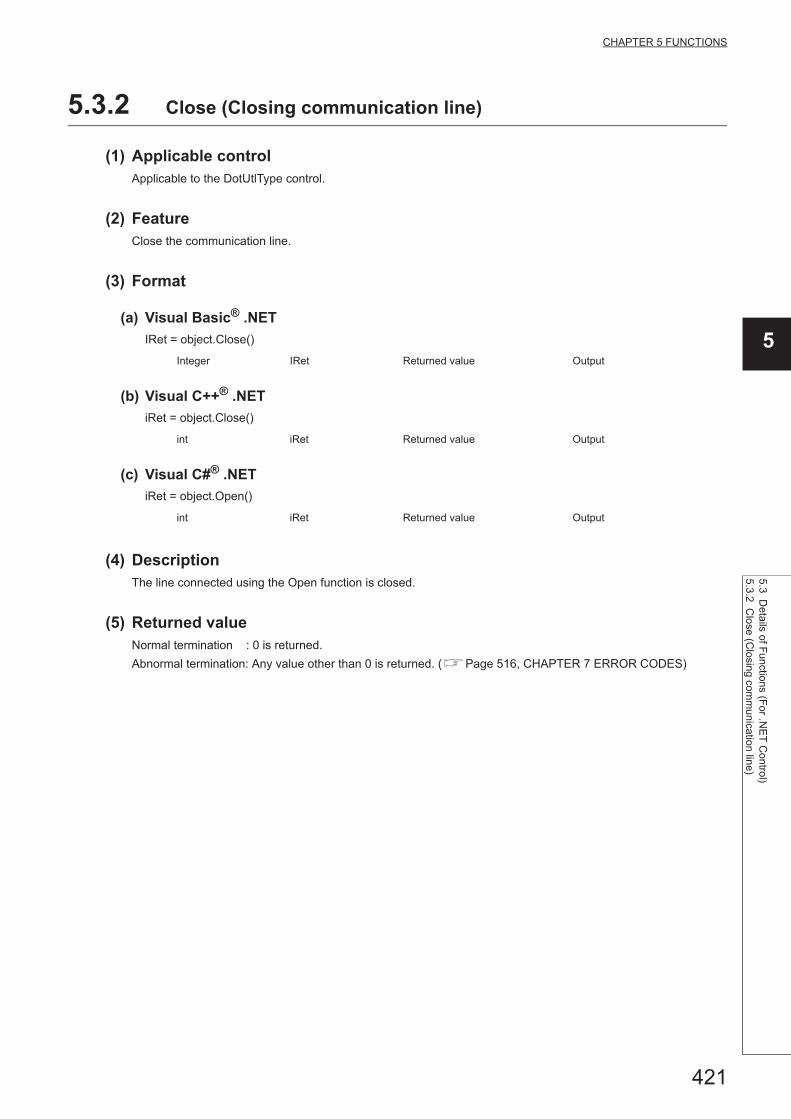
421
CHAPTER 5 FUNCTIONS
5
5.3 Details of F
unctions (For .N
ET
Control)
5.3.2 Close (C
losing comm
unication line)
5.3.2 Close (Closing communication line)
(1) Applicable controlApplicable to the DotUtlType control.
(2) FeatureClose the communication line.
(3) Format
(a) Visual Basic® .NET
IRet = object.Close()
(b) Visual C++® .NET
iRet = object.Close()
(c) Visual C#® .NET
iRet = object.Open()
(4) DescriptionThe line connected using the Open function is closed.
(5) Returned valueNormal termination : 0 is returned.
Abnormal termination: Any value other than 0 is returned. (Page 516, CHAPTER 7 ERROR CODES)
Integer IRet Returned value Output
int iRet Returned value Output
int iRet Returned value Output

422
5.3.3 ReadDeviceBlock (Reading devices in bulk)
(1) Applicable controlApplicable to the DotUtlType control.
(2) FeatureRead devices in bulk.
(3) Format
(a) Visual Basic® .NET
IRet = object.ReadDeviceBlock(szLabel, iSize, iData(0))
(b) Visual C++® .NET
iRet = object.ReadDeviceBlock(*szLabel, iSize, *ipiData)
(c) Visual C#® .NET
iRet = object.ReadDeviceBlock(ref szLabel, iSize, ref iData)
(4) Description • The devices for the amount specified for iSize (number of read points) are read in bulk starting from the
device specified for szLabel (label name).
• The read device values are stored in iData (ipiData).
• For iData (ipiData), reserve arrays for more than the amount specified for iSize.
Integer IRet Returned value Output
String szLabel Label name Input
Integer iSize Number of read points Input
Integer iData(n) Read device values Output
Int iRet Returned value Output
String* szLabel Label name Input
int iSize Number of read points Input
int* ipiData Read device values Output
Int iRet Returned value Output
String szLabel Label name Input
int iSize Number of read points Input
int(n) iData Read device values Output

423
CHAPTER 5 FUNCTIONS
5
5.3 Details of F
unctions (For .N
ET
Control)
5.3.3 ReadD
eviceBlock (R
eading devices in bulk)
(5) How to specify devicesThe following describes how to specify label names and device values to be read.
• The following data type can be specified for label name.
*1 : The maximum number of characters that can be specified is 32 + NULL
• Set the following values for the number of read points according to the label data type.
• The read device values are stored as follows.
Type class Label data type Label name format
Array
Label name
Member
Bit, Word, Double Word,
Float (Single Precision), Float (Double Precision),
String*1, String (Unicode)*1, Time, Timer, Long timer,
Counter, Long counter,
Retentive Timer, Long retentive timer
Label name [number of elements]
Label name [n1] [n2] [n3]
Label (array) data typeNumber of
applicable wordsNumber of read points to be specified
Bit 1 Number of label array elements divided by 16 (rounded up)
Word 1 Number of label array elements
Double Word, Float (Single Precision) 2 Number of label array elements multiplied by 2
Float (Double Precision) 4 Number of label array elements multiplied by 4
String 17 Number of label array elements multiplied by 17
String (Unicode) 33 Number of label array elements multiplied by 33
Time 2 Number of label array elements multiplied by 2
Timer, Long timer,
Counter, Long counter,
Retentive Timer, Long retentive timer
1 Number of label array elements
<When bit device is specified> <When word device is specified>
Example: Read 3 points of data (3 words = 48 bits) from
the devices starting from M0.
• Label setting (Data type: Bit, Number of array elements:
48)
• Number of read points: 3
• Read device values
*2 : Devices are stored from the lower bit in the order of device number.
Example: Read 3 points of data from the devices starting
from D0.
• Label setting (Data type: Word, Number of array
elements: 3)
• Number of read points: 3
• Read device values
Data type Device
Bit (0..47) M0
Upper 2 bytes Lower 2 bytes
Not used
(0 is stored.)
M0 to M15*2
M16 to M31*2
M32 to M47*2
Data type Device
Word (0..2) D0
Upper 2 bytes Lower 2 bytes
Not used
(0 is stored.)
D0
D1
D2

424
<When FXCPU devices of CN200 and later are specified> <When FD device is specified (4-word device)>
Example: Read 6 points of data from the devices starting
from CN200.*3
• Label setting (Data type: Double Word, Number of array
elements: 3)
• Number of read points: 6
• Read device values
*3 : For FXCPU devices of CN200 and later, 2 points of data are read from each 1 point of device (upper (H) and lower (L) data).Reading only 1 point of data will result in an error.
Example: Read 8 points of data from the devices starting
from FD0.
• Label setting (Data type: Double Word, Number of array
elements: 2)
• Number of read points: 8
• Read device values
<When label is Double Word array and word device is
specified>
<When long timer, long counter, or long retentive timer
type is specified>
Example: Read 6 points of data from the devices starting
from D100.
• Label setting (Data type: Double Word, Number of array
elements: 3)
• Number of read points: 6
• Read device values
Example: Read 3 points of data from the devices starting
from LT0.
• Label setting (Data type: Long timer, Number of array
elements: 3)
• Number of read points: 3
• Read device values
Data type Device
Double Word (0..2) CN200
Upper 2 bytes Lower 2 bytes
Not used
(0 is stored.)
L of CN200
H of CN200
L of CN201
H of CN201
L of CN202
H of CN202
Data type Device
Double Word (0..1) FD0
Upper 2 bytes Lower 2 bytes
Not used
(0 is stored.)
LL of FD0
LH of FD0
HL of FD0
HH of FD0
LL of FD1
LH of FD1
HL of FD1
HH of FD1
Data type Device
Double Word (0..2) D100
Upper 2 bytes Lower 2 bytes
Not used
(0 is stored.)
D100
D101
D102
D103
D104
D105
Data type Device
Long timer (0..2) LT0
Upper 2 bytes Lower 2 bytes
H of LT0 L of LT0
H of LT1 L of LT1
H of LT2 L of LT2

425
CHAPTER 5 FUNCTIONS
5
5.3 Details of F
unctions (For .N
ET
Control)
5.3.3 ReadD
eviceBlock (R
eading devices in bulk)
(6) Returned valueNormal termination : 0 is returned.
Abnormal termination: Any value other than 0 is returned. (Page 516, CHAPTER 7 ERROR CODES)
● The maximum number of read points should be the value which satisfies the following condition.Read start device number + Number of read points Last device number
● When specifying bit type array labels, 0 or a multiple of 16 can be specified as a device number.
● For the number of read points, specify the number of words which applies to the data type specified for the label name. For the read device values, reserve a memory area for the number of points specified for the number of read points. If the memory area is not reserved, a critical error (an application error or the like) may occur.
● When a device which corresponds to the label name does not exist, an error occurs and data cannot be read.When any one of devices which correspond to multiple label names does not exist, an error occurs and data cannot be read.
● Digit specified bit device and index setting cannot be used.
● When using system label Ver.2, the data type defined in the Label Utility of MX Component and the data type managed by MELSOFT Navigator is required to match.If the data type does not match, the read data length may wrong, or when multiple labels are specified, the correspondence of the array of the read device value and label name may not match.

426
5.3.4 WriteDeviceBlock (Writing devices in bulk)
(1) Applicable controlApplicable to the DotUtlType control.
(2) FeatureWrite devices in bulk.
(3) Format
(a) Visual Basic® .NET
Ret = object.WriteDeviceBlock(szLabel, iSize, iData(0))
(b) Visual C++® .NET
iRet = object.WriteDeviceBlock(*szLabel, iSize, *ipiData)
(c) Visual C#® .NET
iRet = object.WriteDeviceBlock(ref szLabel, iSize, iData)
(4) Description • The devices for the amount specified for iSize (number of write points) are written in bulk starting from the
device specified for szLabel (label name). • The device values to be written are stored in iData (ipiData). • For iData (ipiData), reserve arrays for more than the amount specified for iSize.
(5) How to specify devicesThe following describes how to specify label names and device values to be written.
• The following data type can be specified for label name.
*1 : The maximum number of characters that can be specified is 32 + NULL
Integer IRet Returned value Output
String szLabel Label name Input
Integer iSize Number of write points Input
Integer iData(n) Device values to be written Input
int iRet Returned value Output
String* szLabel Label name Input
int iSize Number of write points Input
int* ipiData Device values to be written Input
int iRet Returned value Output
String szLabel Label name Input
int iSize Number of write points Input
int(n) iData Device values to be written Input
Type class Label data type Label name format
Array
Label name
Member
Bit, Word, Double Word,Float (Single Precision), Float (Double Precision),
String*1, String (Unicode)*1, Time, Timer, Long timer,
Counter, Long counter,
Retentive Timer, Long retentive timer
Label name [number of elements]Label name [n1] [n2] [n3]

427
CHAPTER 5 FUNCTIONS
5
5.3 Details of F
unctions (For .N
ET
Control)
5.3.4 WriteD
eviceBlock (W
riting devices in bulk)
• Set the following values for the number of write points according to the label data type.
• Set the device values to be written as follows.
Label (array) data typeNumber of
applicable wordsNumber of read points to be specified
Bit 1 Number of label array elements divided by 16 (rounded up)
Word 1 Number of label array elements
Double Word, Float (Single Precision) 2 Number of label array elements multiplied by 2
Float (Double Precision) 4 Number of label array elements multiplied by 4
String 17 Number of label array elements multiplied by 17
String (Unicode) 33 Number of label array elements multiplied by 33
Time 2 Number of label array elements multiplied by 2
Timer, Long timer, Counter, Long
counter, Retentive Timer, Long
retentive timer
1 Number of label array elements
<When bit device is specified> <When word device is specified>
Example: Write 3 points of data (3 words = 48 bits) to the
devices starting from M0.
• Label setting (Data type: Bit, Number of array elements: 48)
• Number of write points: 3• Device values to be written
*2 : Devices are stored from the lower bit in the order of device number.
Example: Write 3 points of data to the devices starting
from D0.
• Label setting (Data type: Word, Number of array
elements: 3)
• Number of write points: 3• Device values to be written
<When FXCPU devices of CN200 and later are specified> <When FD device is specified (4-word device)>
Example: Write 6 points of data to the devices starting
from CN200.*3
• Label setting (Data type: Double Word, Number of array
elements: 3)
• Number of write points: 6
• Device values to be written
*3 : For FXCPU devices of CN200 and later, 2 points of data are written to each 1 point of device (upper (H) and lower (L) data).Writing only 1 point of data will result in an error.
Example: Write 8 points of data to the devices starting
from FD0.
• Label setting (Data type: Double Word, Number of array
elements: 2)
• Number of write points: 8
• Device values to be written
Data type Device
Bit (0..47) M0
Upper 2 bytes Lower 2 bytes
Not used
M0 to M15*2
M16 to M31*2
M32 to M47*2
Data type Device
Word (0..2) D0
Upper 2 bytes Lower 2 bytes
Not used
D0
D1
D2
Data type Device
Double Word (0..2) CN200
Upper 2 bytes Lower 2 bytes
Not used
L of CN200
H of CN200
L of CN201
H of CN201
L of CN202
H of CN202
Data type Device
Double Word (0..1) FD0
Upper 2 bytes Lower 2 bytes
Not used
LL of FD0
LH of FD0
HL of FD0
HH of FD0
LL of FD1
LH of FD1
HL of FD1
HH of FD1

428
(6) Returned valueNormal termination : 0 is returned.
Abnormal termination: Any value other than 0 is returned. (Page 516, CHAPTER 7 ERROR CODES)
● The maximum number of write points should be the value which satisfies the following condition.Write starting device number + Number of write points Last device number
● When specifying bit type array labels, 0 or a multiple of 16 can be specified as a device number.
● For the number of write points, specify the number of words which applies to the data type specified for the label name. For the device values to be written, reserve a memory area for the number of points specified for the number of write points. If the memory area is not reserved, a critical error (an application error or the like) may occur.
● When a device which corresponds to the label name does not exist, an error occurs and data cannot be written.When any one of devices which correspond to multiple label names does not exist, an error occurs and data cannot be written.
● Digit specified bit device and index setting cannot be used.
● WriteDeviceBlock cannot be used for writing long timer device (LT) and retentive long timer device (LST).Use WriteDeviceRandom or SetDevice.
● When using system label Ver.2, the data type defined in the Label Utility of MX Component and the data type managed by MELSOFT Navigator is required to match.If the data type does not match, the read data length may wrong, or when multiple labels are specified, the correspondence of the array of the read device value and label name may not match.
<When label is Double Word array and word device is
specified>
<When long timer, long counter, or long retentive timer
type is specified>
Example: Write 6 points of data to the devices starting
from D100.
• Label setting (Data type: Double Word, Number of array
elements: 3)
• Number of write points: 6
• Device values to be written
Example: Write 3 points of data from the devices starting
from LT0.
• Label setting (Data type: Long timer, Number of array
elements: 3)
• Number of write points: 3
• Device values to be written
Data type Device
Double Word (0..2) D100
Upper 2 bytes Lower 2 bytes
Not used
D100
D101
D102
D103
D104
D105
Data type Device
Long timer (0..2) LT0
Upper 2 bytes Lower 2 bytes
H of LT0 L of LT0
H of LT1 L of LT1
H of LT2 L of LT2

429
CHAPTER 5 FUNCTIONS
5
5.3 Details of F
unctions (For .N
ET
Control)
5.3.5 ReadD
eviceRa
ndom (R
eading
devices randomly)
5.3.5 ReadDeviceRandom (Reading devices randomly)
(1) Applicable controlApplicable to the DotUtlType control.
(2) FeatureRead devices randomly.
(3) Format
(a) Visual Basic® .NET
IRet = object.ReadDeviceRandom(szLabel, iSize, iData(0))
IRet = object.ReadDeviceRandom(szLabelList, iSize, iData(0))
(b) Visual C++® .NET
iRet = object.ReadDeviceRandom(*szLabel, iSize, *ipiData)
iRet = object.ReadDeviceRandom(**szLabelList, iSize, *arriData)
(c) Visual C#® .NET
iRet = object.ReadDeviceRandom(ref szLabel, iSize, ref iData)
iRet = object.ReadDeviceRandom(ref szLabelList, iSize, ref iData)
Integer IRet Returned value Output
String szLabel Label name Input
Integer iSize Number of read points Input
Integer iData(n) Read device values Output
Integer IRet Returned value Output
String szLabelList(n) Label list Input
Integer iSize Number of read points Input
Integer iData(n) Read device values Output
Int iRet Returned value Output
String* szLabel Label name Input
int iSize Number of read points Input
int* ipiData Read device values Output
Int iRet Returned value Output
String** szLabelList Label list Input
int iSize Number of read points Input
int* ipiData Read device values Output
Int iRet Returned value Output
String szLabel Label name Input
int iSize Number of read points Input
int(n) iData Read device values Output
Int iRet Returned value Output
System.String() szLabelList Label list Input
int iSize Number of read points Input
int(n) iData Read device values Output

430
(4) Description • Data of a device group for the size of iSize specified for the label name szLabel (szLabelList) are read.
• The read device values are stored in iData (ipiData).
• For iData (ipiData), reserve arrays for more than the amount specified for iSize.
(5) How to specify devicesThe following describes how to specify label names and device values to be read.
• The following data type can be specified for label name.
*1 : The maximum number of characters that can be specified is 32 + NULL.
• For the number of read points, specify the sum of the following values correspond to the elements according
to the label data type.
Type class Label data type Label name format
Basic type
Bit, Word, Double Word,
Float (Single Precision),
Float (Double Precision),
String*1, String (Unicode)*1, Time,
Timer, Long timer,
Counter, Long counter,
Retentive Timer, Long retentive timer
Label name
Array
Label name
Member
(The label data type can be specified
in the same manner as the basic
type.)
Label name [number of elements]
Label name [n1] [n2] [n3]
Structure
Label name
Member
(The label data type can be specified
in the same manner as the basic
type.)
Label name.Member name
Structured
array
Label name [number of elements]
Member
(The label data type can be specified
in the same manner as the basic
type.)
Label name [number of elements].Member
name
Label name [n1] [n2] [n3].Element
Label data typeNumber of
applicable wordsNumber of read points to be specified
Bit, Word 1 Number of label elements
Double Word, Float (Single Precision) 2 Number of label elements multiplied by 2
Float (Double Precision) 4 Number of label elements multiplied by 4
String 17 Number of label elements multiplied by 17
String (Unicode) 33 Number of label array elements multiplied by 33
Time 2 Number of label elements multiplied by 2
Timer, Long timer,
Counter, Long counter,
Retentive Timer, Long retentive timer
1 Number of label elements

431
CHAPTER 5 FUNCTIONS
5
5.3 Details of F
unctions (For .N
ET
Control)
5.3.5 ReadD
eviceRa
ndom (R
eading
devices randomly)
• The read device values are stored as follows.
<When bit device and word device are specified>
Example: Read data from each 1 point of M0 and D0.
• Label setting
• Number of read points: 2
• Read device values
*1 : The device to be read is 1 point of "M0", and "0" or "1" is stored for the device value.
<When FXCPU devices of CN200 and later are specified> <When FD device is specified (4-word device)>
Example: Read 3 points of data from the devices including
CN200.*2
• Label setting
• Number of read points: 3
• Read device values
*2 : For FXCPU devices of CN200 and later, 4 bytes are read as 1 read point.
Example: Read 3 points of data from the devices including
FD0.
• Label setting
• Number of read points: 3
• Read device values
*3 : Only lower 2 bytes are read. Data are not read from the specified devices HH, HL, and LH (upper 6 bytes).
szLabelList Data type Device
[0] LABEL1 Bit M0
[1] LABEL2 Word D0
Upper 2
bytes
Lower 2
bytes
Applicable
label
Not used
(0 is stored.)
M0*1 LABEL1
D0 LABEL2
szLabelList Data type Device
[0] LABEL1 Word D0
[1] LABEL2 Double Word CN200
[2] LABEL3 Word D1
Upper 2
bytes
Lower 2
bytes
Applicable
label
Not used
(0 is stored.)D0 LABEL1
H of CN200 L of CN200 LABEL2
Not used
(0 is stored.)D1 LABEL3
szLabelList Data type Device
[0] LABEL1 Word D0
[1] LABEL2 Double Word FD0
[2] LABEL3 Word D1
Upper 2
bytes
Lower 2
bytes
Applicable
label
Not used
(0 is stored.)
D0 LABEL1
LL of FD0*3 LABEL2
D1 LABEL3

432
<When data type equivalent to 2 words or more is
specified for label><When array type label is specified>
Example: Read data by specifying labels of Double Word,
Float (Single Precision), Float (Double Precision), String*4,
and Time types.
• Label setting
• Number of read points: 27
• Read device values
*4 : The number of points of characters to be read is 17 (32 characters + NULL). The characters need to be converted in a user program because the characters of String type are not converted.
Example: Read data from the devices by specifying array
type labels.
• Label setting
• Number of read points: 8
• Read device values
<When long timer, long counter, or long retentive timer type is specified>
Example: Read 3 points of data from LT0.
• Label setting
• Number of read points: 3
• Read device values
szLabelList Data type Device
[0] LABEL1 Double Word D0
[1] LABEL2Float (Single
Precision)D100
[2] LABEL3Float (Double
Precision)D200
[3] LABEL4 String D300
[4] LABEL5 Time D400
Upper 2 bytes
Lower 2 bytes
Applicable label
Not used
(0 is stored.)
D0LABEL1
D1
D100LABEL2
D101
D200
LABEL3D201
D202
D203
D300
:
D316*4
LABEL4
D400LABEL5
D401
szLabelList Data type Device
[0] LABEL1 Bit (0..1) M0
[1] LABEL2 Double Word (0..1) CN200
[2] LABEL3 Double Word (0..1) D0
Upper 2 bytes
Lower 2 bytes
Applicable label
Not used
(0 is stored.)
M0 LABEL1[0]
M1 LABEL1[1]
H of CN200 L of CN200 LABEL2[0]
H of CN201 L of CN201 LABEL2[1]
Not used
(0 is stored.)
D100LABEL3[0]
D101
D102LABEL3[1]
D103
szLabelList Data type Device
[0] LABEL Long timer LT0
[1] LABEL Long timer LT1
[2] LABEL Long timer LT2
Upper 2 bytes
Lower 2 bytes
Applicable label
H of LT0 D0 LABEL[1]
H of LT1 L of CN200 LABEL[2]
H of LT2 D1 LABEL[3]
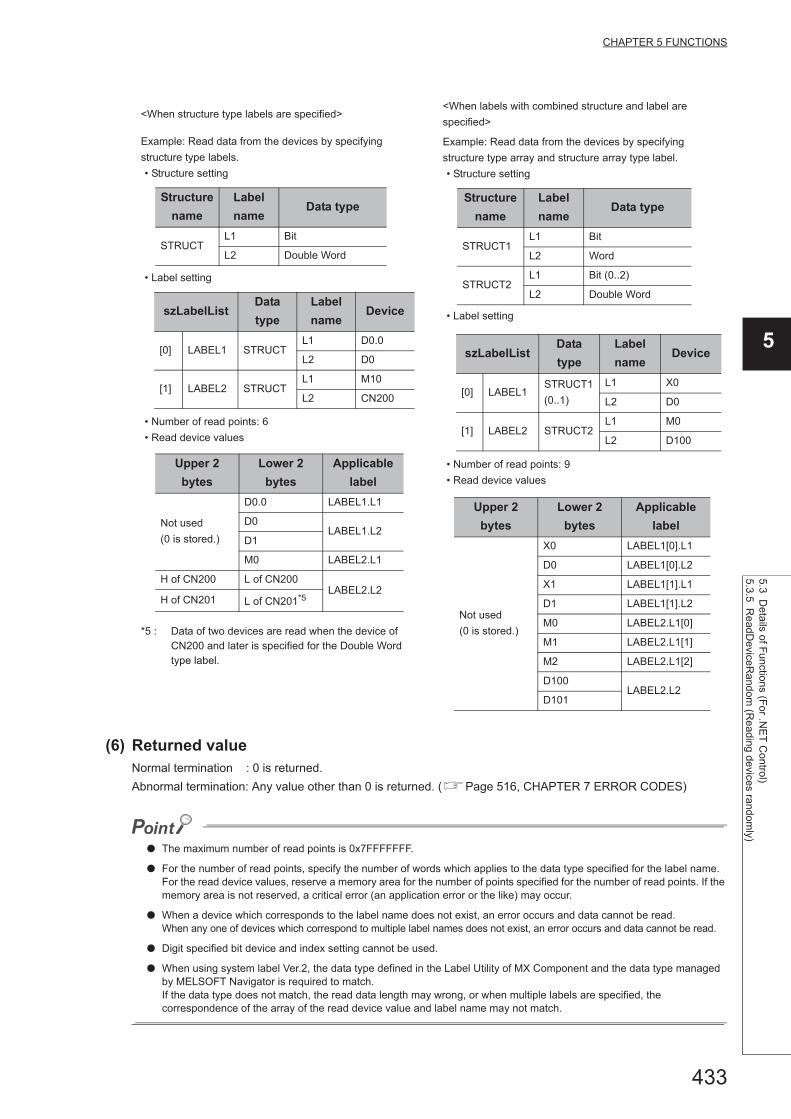
433
CHAPTER 5 FUNCTIONS
5
5.3 Details of F
unctions (For .N
ET
Control)
5.3.5 ReadD
eviceRa
ndom (R
eading
devices randomly)
(6) Returned valueNormal termination : 0 is returned.
Abnormal termination: Any value other than 0 is returned. (Page 516, CHAPTER 7 ERROR CODES)
● The maximum number of read points is 0x7FFFFFFF.
● For the number of read points, specify the number of words which applies to the data type specified for the label name. For the read device values, reserve a memory area for the number of points specified for the number of read points. If the memory area is not reserved, a critical error (an application error or the like) may occur.
● When a device which corresponds to the label name does not exist, an error occurs and data cannot be read.When any one of devices which correspond to multiple label names does not exist, an error occurs and data cannot be read.
● Digit specified bit device and index setting cannot be used.
● When using system label Ver.2, the data type defined in the Label Utility of MX Component and the data type managed by MELSOFT Navigator is required to match.If the data type does not match, the read data length may wrong, or when multiple labels are specified, the correspondence of the array of the read device value and label name may not match.
<When structure type labels are specified><When labels with combined structure and label are
specified>
Example: Read data from the devices by specifying
structure type labels.
• Structure setting
• Label setting
• Number of read points: 6
• Read device values
*5 : Data of two devices are read when the device of CN200 and later is specified for the Double Word type label.
Example: Read data from the devices by specifying
structure type array and structure array type label.
• Structure setting
• Label setting
• Number of read points: 9
• Read device values
Structure
name
Label
nameData type
STRUCTL1 Bit
L2 Double Word
szLabelListData
type
Label
nameDevice
[0] LABEL1 STRUCTL1 D0.0
L2 D0
[1] LABEL2 STRUCTL1 M10
L2 CN200
Upper 2
bytes
Lower 2
bytes
Applicable
label
Not used
(0 is stored.)
D0.0 LABEL1.L1
D0LABEL1.L2
D1
M0 LABEL2.L1
H of CN200 L of CN200LABEL2.L2
H of CN201 L of CN201*5
Structure
name
Label
nameData type
STRUCT1L1 Bit
L2 Word
STRUCT2L1 Bit (0..2)
L2 Double Word
szLabelListData
type
Label
nameDevice
[0] LABEL1STRUCT1
(0..1)
L1 X0
L2 D0
[1] LABEL2 STRUCT2L1 M0
L2 D100
Upper 2
bytes
Lower 2
bytes
Applicable
label
Not used
(0 is stored.)
X0 LABEL1[0].L1
D0 LABEL1[0].L2
X1 LABEL1[1].L1
D1 LABEL1[1].L2
M0 LABEL2.L1[0]
M1 LABEL2.L1[1]
M2 LABEL2.L1[2]
D100LABEL2.L2
D101
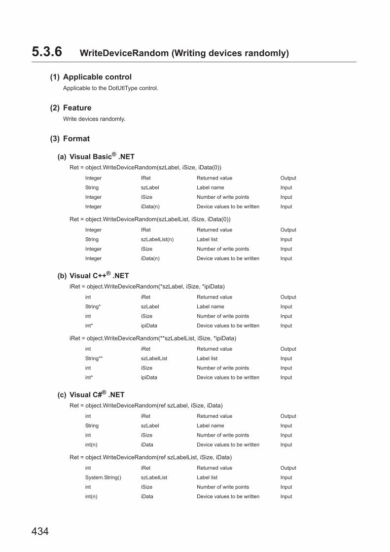
434
5.3.6 WriteDeviceRandom (Writing devices randomly)
(1) Applicable controlApplicable to the DotUtlType control.
(2) FeatureWrite devices randomly.
(3) Format
(a) Visual Basic® .NET
Ret = object.WriteDeviceRandom(szLabel, iSize, iData(0))
Ret = object.WriteDeviceRandom(szLabelList, iSize, iData(0))
(b) Visual C++® .NET
iRet = object.WriteDeviceRandom(*szLabel, iSize, *ipiData)
iRet = object.WriteDeviceRandom(**szLabelList, iSize, *ipiData)
(c) Visual C#® .NET
Ret = object.WriteDeviceRandom(ref szLabel, iSize, iData)
Ret = object.WriteDeviceRandom(ref szLabelList, iSize, iData)
Integer IRet Returned value Output
String szLabel Label name Input
Integer iSize Number of write points Input
Integer iData(n) Device values to be written Input
Integer IRet Returned value Output
String szLabelList(n) Label list Input
Integer iSize Number of write points Input
Integer iData(n) Device values to be written Input
int iRet Returned value Output
String* szLabel Label name Input
int iSize Number of write points Input
int* ipiData Device values to be written Input
int iRet Returned value Output
String** szLabelList Label list Input
int iSize Number of write points Input
int* ipiData Device values to be written Input
int iRet Returned value Output
String szLabel Label name Input
int iSize Number of write points Input
int(n) iData Device values to be written Input
int iRet Returned value Output
System.String() szLabelList Label list Input
int iSize Number of write points Input
int(n) iData Device values to be written Input

435
CHAPTER 5 FUNCTIONS
5
5.3 Details of F
unctions (For .N
ET
Control)
5.3.6 WriteD
eviceRandom
(Writing devices ra
ndomly)
(4) Description • Data of a device group for the size of iSize specified for the label name szLabel (szLabelList) are written.
• The device values to be written are stored in iData (ipiData).
• For iData (ipiData), reserve arrays for more than the amount specified for iSize.
(5) How to specify devicesThe following describes how to specify label names and device values to be written.
• The following data type can be specified for label name.
*1 : The maximum number of characters that can be specified is 32 + NULL.
• For the number of write points, specify the sum of the following values correspond to the elements according
to the label data type.
Type class Label data type Label name format
Basic type
Bit, Word, Double Word,
Float (Single Precision),
Float (Double Precision),
String*1, String (Unicode)*1, Time,
Timer, Long timer,
Counter, Long counter,
Retentive Timer, Long retentive timer
Label name
Array
Label name
Member
(The label data type can be specified
in the same manner as the basic
type.)
Label name [number of elements]
Label name [n1] [n2] [n3]
Structure
Label name
Member
(The label data type can be specified
in the same manner as the basic
type.)
Label name.Member name
Structured
array
Label name [number of elements]
Member
(The label data type can be specified
in the same manner as the basic
type.)
Label name [number of elements].Member name
Label name [n1] [n2] [n3].Element
Label data typeNumber of
applicable wordsNumber of write points to be specified
Bit, Word 1 Number of label elements
Double Word, Float (Single Precision) 2 Number of label elements multiplied by 2
Float (Double Precision) 4 Number of label elements multiplied by 4
String 17 Number of label elements multiplied by 17
String (Unicode) 33 Number of label array elements multiplied by 33
Time 2 Number of label elements multiplied by 2
Timer, Long timer,
Counter, Long counter,
Retentive Timer, Long retentive timer
1 Number of label elements

436
• Set the device values to be written as follows.
<When bit device and word device are specified>
Example: Write data to each 1 point of M0 and D0.
• Label setting
• Number of write points: 2
• Device values to be written
<When FXCPU devices of CN200 and later are specified> <When FD device is specified (4-word device)>
• Example: Write 3 points of data to the devices including
CN200.*1
• Label setting
• Number of write points: 3
• Device values to be written
*1 : For FXCPU devices of CN200 and later, 4 bytes are written as 1 read point.
Example: Write 3 points of data to the devices including
FD0.
• Label setting
• Number of write points: 3
• Device values to be written
*2 : Only lower 2 bytes can be set. "0" is written to the specified devices HH, HL, and LH (upper 6 bytes).
szLabelList Data type Device
[0] LABEL1 Bit M0
[1] LABEL2 Word D0
Upper 2
bytes
Lower 2
bytes
Applicable
label
Not used M0 LABEL1
D0 LABEL2
szLabelList Data type Device
[0] LABEL1 Word D0
[1] LABEL2 Double Word CN200
[2] LABEL3 Word D1
Upper 2
bytes
Lower 2
bytes
Applicable
label
Not used D0 LABEL1
H of CN200 L of CN200 LABEL2
Not used D1 LABEL3
szLabelList Data type Device
[0] LABEL1 Word D0
[1] LABEL2 Double Word FD0
[2] LABEL3 Word D1
Upper 2
bytes
Lower 2
bytes
Applicable
label
Not used
D0 LABEL1
LL of FD0*2 LABEL2
D1 LABEL3

437
CHAPTER 5 FUNCTIONS
5
5.3 Details of F
unctions (For .N
ET
Control)
5.3.6 WriteD
eviceRandom
(Writing devices ra
ndomly)
<When data type equivalent to 2 words or more is
specified for label><When array type label is specified>
Example: Write data by specifying labels of Double Word,
Float (Single Precision), Float (Double Precision), String*3,
and Time types.
• Label setting
• Number of write points: 27
• Device values to be written
*3 : The number of points of characters to be written is 17 (32 characters + NULL). The characters need to be converted in a user program because the characters of String type are not converted.
Example: Write data to the devices by specifying array type
labels.
• Label setting
• Number of write points: 8
• Device values to be written
<When long timer, long counter, or long retentive timer type is specified>
Example: Write 3 points of data from LT0.
• Label setting
• Number of write points: 3
• Device values to be written
szLabelList Data type Device
[0] LABEL1 Double Word D0
[1] LABEL2Float (Single
Precision)D100
[2] LABEL3Float (Double
Precision)D200
[3] LABEL4 String D300
[4] LABEL5 Time D400
Upper 2 bytes
Lower 2 bytes
Applicable label
Not used
D0LABEL1
D1
D100LABEL2
D101
D200
LABEL3D201
D202
D203
D300
:
D316*3
LABEL4
D400LABEL5
D401
szLabelList Data type Device
[0] LABEL1 Bit (0..1) M0
[1] LABEL2 Double Word (0..1) CN200
[2] LABEL3 Double Word (0..1) D0
Upper 2 bytes
Lower 2 bytes
Applicable label
Not used
(0 is stored.)
M0 LABEL1[0]
M1 LABEL1[1]
H of CN200 L of CN200 LABEL2[0]
H of CN201 L of CN201 LABEL2[1]
Not used
D100LABEL3[0]
D101
D102LABEL3[1]
D103
szLabelList Data type Device
[0] LABEL Long timer LT0
[1] LABEL Long timer LT1
[2] LABEL Long timer LT2
Upper 2 bytes
Lower 2 bytes
Applicable label
H of LT0 L of LT0 LABEL[1]
H of LT1 L of LT1 LABEL[2]
H of LT2 L of LT2 LABEL[3]

438
<When structure type labels are specified><When labels with combined structure and label are
specified>
Example: Write data to the devices by specifying structure
type labels.
• Structure setting
• Label setting
• Number of write points: 5
• Device values to be written
Example: Write data to the devices by specifying structure
type array and structure array type label.
• Structure setting
• Label setting
• Number of write points: 9
• Device values to be written
Structure
name
Label
nameData type
STRUCTL1 Bit
L2 Double Word
szLabelListData
type
Label
nameDevice
[0] LABEL1 STRUCTL1 D0.0
L2 D0
[1] LABEL2 STRUCTL1 M10
L2 CN200
Upper 2
bytes
Lower 2
bytes
Applicable
label
Not used
D0.0 LABEL1.L1
D0LABEL1.L2
D1
M0 LABEL2.L1
H of CN200 L of CN200 LABEL2.L2
Structure
name
Label
nameData type
STRUCT1L1 Bit
L2 Word
STRUCT2L1 Bit (0..2)
L2 Double Word
szLabelListData
type
Label
nameDevice
[0] LABEL1STRUCT1
(0..1)
L1 X0
L2 D0
[1] LABEL2 STRUCT2L1 M0
L2 D100
Upper 2
bytes
Lower 2
bytes
Applicable
label
Not used
X0 LABEL1[0].L1
D0 LABEL1[0].L2
X1 LABEL1[1].L1
D1 LABEL1[1].L2
M0 LABEL2.L1[0]
M1 LABEL2.L1[1]
M2 LABEL2.L1[2]
D100LABEL2.L2
D101

439
CHAPTER 5 FUNCTIONS
5
5.3 Details of F
unctions (For .N
ET
Control)
5.3.6 WriteD
eviceRandom
(Writing devices ra
ndomly)
(6) Returned valueNormal termination : 0 is returned.Abnormal termination: Any value other than 0 is returned. (Page 516, CHAPTER 7 ERROR CODES)
● The maximum number of write points is 0x7FFFFFFF.
● For the number of write points, specify the number of words which applies to the data type specified for the label name. For the device values to be written, reserve a memory area for the number of points specified for the number of write points. If the memory area is not reserved, a critical error (an application error or the like) may occur.
● When a device which corresponds to the label name does not exist, an error occurs and data cannot be written.When any one of devices which correspond to multiple label names does not exist, an error occurs and data cannot be written.
● Digit specified bit device and index setting cannot be used.
● If a Q motion CPU is accessed, an error is returned.
● When using system label Ver.2, the data type defined in the Label Utility of MX Component and the data type managed by MELSOFT Navigator is required to match.If the data type does not match, the read data length may wrong, or when multiple labels are specified, the correspondence of the array of the read device value and label name may not match.
<When a structure type label, in which the structure type is included in the element, is specified>
Example: Write data from the devices by specifying structure type labels in which the structure type is included in the
element.
• Structure setting
• Label setting
• Number of write points: 8• Device values to be written
Structure
name
Label
nameData type
STRUCT1
LABEL11 Bit
LABEL12 Word
LABEL13 Structure type(STRUCT2)
STRUCT2LABEL21 Double Word
LABEL22 Float (Double Precision)
szLabelListData
type
Label
nameDevice
[0] STRUCT STRUCT1 LABEL11 D0.0
[1] STRUCT STRUCT1 LABEL12 D1
[2] STRUCT STRUCT1
LABEL13,
LABEL21D2
LABEL13,
LABEL22D4
Upper 2
bytes
Lower 2
bytesApplicable label
Not used
(0 is stored.)
D0.0 STRUCT.LABEL11
D1 STRUCT.LABEL12
D2 STRUCT.LABEL13
.LABEL21D3
D4
STRUCT.LABEL13
.LABEL22
D5
D6
D7

440
5.3.7 SetDevice (Setting device data)
(1) Applicable controlApplicable to the DotUtlType control.
(2) FeatureSet one point of device.
(3) Format
(a) Visual Basic® .NET
IRet = object.SetDevice(szLabel, iData)
(b) Visual C++® .NET
iRet = object.SetDevice(*szLabel, iData)
(c) Visual C#® .NET
iRet = object.SetDevice(ref szLabel, iData)
(4) Description • The values of iData (device values to be written) are written to 1 point of device specified for szLabel (label
name).
• When specifying bit devices, the least significant bit of the iData (device values to be written) is valid.
(5) How to specify devicesThe following describes how to specify label names and device values to be written.
• The following data type can be specified for label name.
*1 : Only lower 2 bytes of start device can be written.When writing 2 words or more of devices, use the WriteDeviceBlock function.Note that when any of the following devices is specified, the upper 2 bytes are also written in Double Word type.
• Digit specified bit devices • FXCPU devices of CN200 and later
Integer IRet Returned value Output
String szLabel Label name Input
Integer iData Device values to be written Input
int iRet Returned value Output
String* szLabel Label name Input
int iData Device values to be written Input
int iRet Returned value Output
String szLabel Label name Input
int iData Device values to be written Input
Type class Label data type Label name format
Basic type
Bit, Word, Double Word*1, Float (Single Precision)*1,
Float (Double Precision)*1, String*1,
String (Unicode), Time*1,
Timer, Long timer, Counter, Long counter,
Retentive Timer, Long retentive timer
Label name
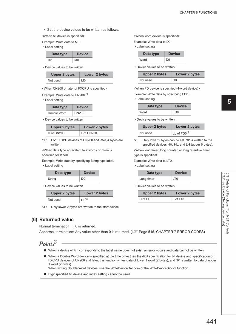
441
CHAPTER 5 FUNCTIONS
5
5.3 Details of F
unctions (For .N
ET
Control)
5.3.7 SetD
evice (Setting device data)
• Set the device values to be written as follows.
(6) Returned valueNormal termination : 0 is returned.
Abnormal termination: Any value other than 0 is returned. (Page 516, CHAPTER 7 ERROR CODES)
● When a device which corresponds to the label name does not exist, an error occurs and data cannot be written.
● When a Double Word device is specified at the time other than the digit specification for bit device and specification of FXCPU devices of CN200 and later, this function writes data of lower 1 word (2 bytes), and "0" is written to data of upper 1 word (2 bytes).When writing Double Word devices, use the WriteDeviceRandom or the WriteDeviceBlock2 function.
● Digit specified bit device and index setting cannot be used.
<When bit device is specified> <When word device is specified>
Example: Write data to M0.
• Label setting
• Device values to be written
Example: Write data to D0.
• Label setting
• Device values to be written
<When CN200 or later of FXCPU is specified> <When FD device is specified (4-word device)>
Example: Write data to CN200.*1
• Label setting
• Device values to be written
*1 : For FXCPU devices of CN200 and later, 4 bytes are written.
Example: Write data by specifying FD0.
• Label setting
• Device values to be written
*2 : Only lower 2 bytes can be set. "0" is written to the specified devices HH, HL, and LH (upper 6 bytes).
<When data type equivalent to 2 words or more is
specified for label>
<When long timer, long counter, or long retentive timer
type is specified>
Example: Write data by specifying String type label.
• Label setting
• Device values to be written
*3 : Only lower 2 bytes are written to the start device.
Example: Write data to LT0.
• Label setting
• Device values to be written
Data type Device
Bit M0
Upper 2 bytes Lower 2 bytes
Not used M0
Data type Device
Word D0
Upper 2 bytes Lower 2 bytes
Not used D0
Data type Device
Double Word CN200
Upper 2 bytes Lower 2 bytes
H of CN200 L of CN200
Data type Device
Word FD0
Upper 2 bytes Lower 2 bytes
Not used LL of FD0*2
Data type Device
String D0
Upper 2 bytes Lower 2 bytes
Not used D0*3
Data type Device
Long timer LT0
Upper 2 bytes Lower 2 bytes
H of LT0 L of LT0

442
5.3.8 GetDevice (Acquiring device data)
(1) Applicable controlApplicable to the DotUtlType control.
(2) FeatureAcquire one point of device.
(3) Format
(a) Visual Basic® .NET
IRet = object.GetDevice(szLabel, iData)
(b) Visual C++® .NET
iRet = object.GetDevice(*szLabel, *ipiData)
(c) Visual C#® .NET
iRet = object.GetDevice(ref szLabel, ref iData)
(4) DescriptionOne point of device data specified for szLabel (label name) is stored in iData (ipiData) (read device values).
(5) How to specify devicesThe following describes how to specify label names and device values to be read.
• The following data type can be specified for label name.
*1 : Only lower 2 bytes of start device can be read.When reading 2 words or more of devices, use the ReadDeviceBlock function.Note that when any of the following devices is specified, the upper 2 bytes are also read in Double Word type.
• Digit specified bit devices • FXCPU devices of CN200 and later
Integer IRet Returned value Output
String szLabel Label name Input
Integer iData Read device values Output
int iRet Returned value Output
String* szLabel Label name Input
int* ipiData Read device values Output
int iRet Returned value Output
String szLabel Label name Input
int iData Read device values Output
Type class Label data type Label name format
Basic type
Bit, Word, Double Word*1, Float (Single Precision)*1,
Float (Double Precision)*1, String*1,
String (Unicode), Time*1,
Timer, Long timer, Counter, Long counter,
Retentive Timer, Long retentive timer
Label name

443
CHAPTER 5 FUNCTIONS
5
5.3 Details of F
unctions (For .N
ET
Control)
5.3.8 GetD
evice (A
cquiring d
evice data)
• The read device values are stored as follows.
(6) Returned valueNormal termination : 0 is returned.
Abnormal termination: Any value other than 0 is returned. (Page 516, CHAPTER 7 ERROR CODES)
● When a device which corresponds to the label name does not exist, an error occurs and data cannot be read.
● For the read device values, reserve 4 bytes of memory area. If the memory area is not reserved, a critical error (an application error or the like) may occur.
● Digit specified bit device and index setting cannot be used.
<When bit device is specified> <When word device is specified>
Example: Read data from M0.
• Label setting
• Read device values
*1 : The device to be read is 1 point of "M0", and "0" or "1" is stored for the device value.
Example: Read data from D0.
• Label setting
• Read device values
<When CN200 or later of FXCPU is specified> <When FD device is specified (4-word device)>
Example: Read data from CN200.*2
• Label setting
• Read device values
*2 : For FXCPU devices of CN200 and later, 4 bytes are read.
Example: Read data by specifying FD0.
• Label setting
• Read device values
*3 : Only lower 2 bytes are read. Data are not read from the specified devices HH, HL, and LH (upper 6 bytes).
<When data type equivalent to 2 words or more is
specified for label>
<When long timer, long counter, or long retentive timer
type is specified>
Example: Read data by specifying String type label.
• Label setting
• Read device values
*4 : Only lower 2 bytes are read to the start device.
Example: Read data to LT0.
• Label setting
• Read device values
Data type Device
Bit M0
Upper 2 bytes Lower 2 bytes
Not used
(0 is stored.)M0*1
Data type Device
Word D0
Upper 2 bytes Lower 2 bytes
Not used
(0 is stored.)D0
Data type Device
Double Word CN200
Upper 2 bytes Lower 2 bytes
H of CN200 L of CN200
Data type Device
Word FD0
Upper 2 bytes Lower 2 bytes
Not used
(0 is stored.)LL of FD0*3
Data type Device
String D0
Upper 2 bytes Lower 2 bytes
Not used
(0 is stored.)D0*4
Data type Device
Long timer LT0
Upper 2 bytes Lower 2 bytes
H of LT0 L of LT0

444
5.3.9 ReadBuffer (Reading data from buffer memory)
(1) Applicable controlApplicable to the DotUtlType control.
(2) FeatureRead data from the buffer memory of special function module.
(3) Format
(a) Visual Basic® .NET
IRet = object.ReadBuffer(iStartIO, iAddress, iReadSize, sData(0))
(b) Visual C++® .NET
iRet = object.ReadBuffer(iStartIO, iAddress, iReadSize, *ipsData)
(c) Visual C#® .NET
iRet = object.ReadBuffer(iStartIO, iAddress, iReadSize, ref sData)
(4) Description • For the start I/O number of the module specified for iStartIO, specify the value of the actual start I/O number
divided by 16.
• Buffer values of buffer memory address specified for iAddress of the special function module of the start I/O
number specified for iStartIO are read for the size of iReadSize.
• When performing CPU COM communication with FXCPU as a connected station or GX Simulator
communication, specify the block number (0 to 7) of the special expansion equipment for the module's start
I/O number and any value between 0 and 32767 for the buffer memory address.
• For sData (ipsData), reserve arrays for more than the amount specified for iReadSize .
Integer lRet Returned value Output
Integer iStartIO Start I/O number of module from Input
Integer iAddress Buffer memory address Input
Integer iReadSize Read size Input
Short sData(n) Values read from buffer memory Output
int iRet Returned value Output
int iStartIO Start I/O number of module from Input
int iAddress Buffer memory address Input
int iReadSize Read size Input
short* ipsData Values read from buffer memory Output
int iRet Returned value Output
int iStartIO Start I/O number of module from Input
int iAddress Buffer memory address Input
int iReadSize Read size Input
short(n) sData Values read from buffer memory Output

445
CHAPTER 5 FUNCTIONS
5
5.3 Details of F
unctions (For .N
ET
Control)
5.3.9 ReadB
uffer (Reading data from
buffer mem
ory)
(5) Returned valueNormal termination : 0 is returned.
Abnormal termination: Any value other than 0 is returned. (Page 516, CHAPTER 7 ERROR CODES)
(6) Considerations for reading/writing data from/to buffer memory in multiple CPU
system configurationAny of the following errors occurs when the function is executed under the situation where the configured multiple
CPU system differs from the I/O assignment set in GX Developer.
Execute the function after checking the I/O assignment set in GX Developer and checking the I/O numbers of the
module from/to which values are read/written.
• An error occurs even when the function is executed after the correct I/O numbers are specified.
• When the specific I/O numbers (I/O numbers whose I/O assignment is actually wrong) are specified,
data can be read from buffer memory normally, but an error (error code: 0x010A4030, 0x010A4042, etc.)
occurs when data are written to the buffer memory.
• Though a programmable controller CPU error (parameter error, SP. UNIT LAY ERR, etc.) does not occur in
the multiple CPU system, an error occurs in the user application when the function is executed.
● If an RCPU, R motion CPU, or Q motion CPU is accessed, an error will be returned.
● For sData (ipsData), reserve a memory area for the number of points specified for iReadSize.If the memory area is not reserved, a critical error (an application error or the like) may occur.
● When reading data from buffer memory (ReadBuffer) on QCPU (Q mode), the read operation can only be performed on the Q series-dedicated modules.Furthermore, data cannot be read from the shared memory of QCPU (Q mode).
● For the availability of communication paths, refer to the table in Page 356, Section 5.2.9.

446
5.3.10 WriteBuffer (Writing data to buffer memory)
(1) Applicable controlApplicable to the DotUtlType control.
(2) FeatureWrite data to the buffer memory of special function module.
(3) Format
(a) Visual Basic® .NET
IRet = object.WriteBuffer(iStartIO, iAddress, iWriteSize, sData(0))
(b) Visual C++® .NET
iRet = object.WriteBuffer(iStartIO, iAddress, iWriteSize, *ipsData)
(c) Visual C#® .NET
IRet = object.WriteBuffer(iStartIO, iAddress, iWriteSize, ref sData)
(4) Description • For the start I/O number of the module specified for iStartIO, specify the value of the actual start I/O number
divided by 16.
• Buffer values of buffer memory address specified for iAddress of the special function module of the start I/O
number specified for iStartIO are written for the size of iWriteSize.
• When performing CPU COM communication with FXCPU as a connected station or GX Simulator
communication, specify the block number (0 to 7) of the special expansion equipment for the module's start
I/O number and any value between 0 and 32767 for the buffer memory address.
• For sData (ipsData), reserve arrays for more than the amount specified for iWriteSize.
Integer lRet Returned value Output
Integer iStartIOStart I/O number of module to
where values will be writtenInput
Integer iAddress Buffer memory address Input
Integer iWriteSize Write size Input
Short sData(n) Values written from buffer memory Input
int iRet Returned value Output
int iStartIOStart I/O number of module to
where values will be writtenInput
int iAddress Buffer memory address Input
int iWriteSize Write size Input
Short* ipsData Values written from buffer memory Input
int iRet Returned value Output
int iStartIOStart I/O number of module to
where values will be writtenInput
int iAddress Buffer memory address Input
int iWriteSize Write size Input
Short(n) sData Values written from buffer memory Input

447
CHAPTER 5 FUNCTIONS
5
5.3 Details of F
unctions (For .N
ET
Control)
5.3.10 WriteB
uffer (Writing data to buffer m
em
ory)
(5) Returned valueNormal termination : 0 is returned.
Abnormal termination: Any value other than 0 is returned. (Page 516, CHAPTER 7 ERROR CODES)
(6) Considerations for reading/writing data from/to buffer memory in multiple CPU
system configurationAny of the following errors occurs when the function is executed under the situation where the configured multiple
CPU system differs from the I/O assignment set in GX Developer.
Execute the function after checking the I/O assignment set in GX Developer and checking the I/O numbers of the
module from/to which the values are read/written.
• An error occurs even when the function is executed after the correct I/O numbers are specified.
• When the specific I/O numbers (I/O numbers whose I/O assignment is actually wrong) are specified,
data can be read from buffer memory normally, but an error (error code: 0x010A4030, 0x010A4042, etc.)
occurs when data are written to the buffer memory.
• Though a programmable controller CPU error (parameter error, SP. UNIT LAY ERR, etc.) does not occur in
the multiple CPU system, an error occurs in the user application when the function is executed.
● If an RCPU, R motion CPU, or Q motion CPU is accessed, an error will be returned.
● For sData (ipsData), reserve a memory area for the number of points specified for iWriteSize.If the memory area is not reserved, a critical error (an application error or the like) may occur.
● When buffer memory write (WriteBuffer) is performed for QCPU (Q mode), write operation may be performed for only the Q series-dedicated module.Furthermore, data cannot be written to the shared memory of QCPU (Q mode).
● For the availability of communication paths, refer to the table in Page 361, Section 5.2.10.

448
5.3.11 GetClockData (Reading clock data)
(1) Applicable controlApplicable to the DotUtlType control.
(2) FeatureRead clock data from a programmable controller CPU.
(3) Format
(a) Visual Basic® .NET
IRet = object.GetClockData(sYear, sMonth, sDay, sDayOfWeek, sHour, sMinute, sSecond)
(b) Visual C++® .NET
iRet = object.GetClockData(*ipsYear, *ipsMonth, *ipsDay, *ipsDayOfWeek, *ipsHour, *ipsMinute, *ipsSecond)
(c) Visual C#® .NET
hResult = object.GetClockData
(ref sYear, ref sMonth, ref sDay, ref sDayOfWeek, ref sHour, ref sMinute, ref sSecond)
Integer lRet Returned value Output
Short sYear Read year value Output
Short sMonth Read month value Output
Short sDay Read day value Output
Short sDayOfWeek Read day-of-week value Output
Short sHour Read hour value Output
Short sMinute Read minute value Output
Short sSecond Read second value Output
int iRet Returned value Output
short* ipsYear Read year value Output
short* ipsMonth Read month value Output
short* ipsDay Read day value Output
short* ipsDayOfWeek Read day-of-week value Output
short* ipsHour Read hour value Output
short* isMinute Read minute value Output
short* ipsSecond Read second value Output
int iRet Returned value Output
Short sYear Read year value Output
Short sMonth Read month value Output
Short sDay Read day value Output
Short sDayOfWeek Read day-of-week value Output
Short sHour Read hour value Output
Short sMinute Read minute value Output
Short sSecond Read second value Output

449
CHAPTER 5 FUNCTIONS
5
5.3 Details of F
unctions (For .N
ET
Control)
5.3.11 GetC
lockData (R
eading clock data)
(4) Description • An error is returned when the correct clock data is not set to the programmable controller CPU.
• The values stored in sYear (ipsYear) are: four digits of the year for RCPU and QCPU (Q mode) and last two
digits of the year for any other CPUs.
Note that the applicable years for RCPU and QCPU (Q mode) are from 1980 to 2079.
• The values stored in sDayOfWeek (ipsDayOfWeek) are as follows.
(5) Returned valueNormal termination : 0 is returned.
Abnormal termination: Any value other than 0 is returned. (Page 516, CHAPTER 7 ERROR CODES)
● If an R motion CPU or a Q motion CPU is accessed, an error is returned.
● The clock data can be read from FXCPUs with the built-in clock or FXU/FX2C/FX2NC with the RTC cassette.An error is returned when the clock data is read from an FXCPU other than the ones described above.
● Note that an error of transfer time may occur in clock setting.
● For the availability of communication paths, refer to the table in Page 366, Section 5.2.11.
Value Day of Week
0 Sunday
1 Monday
2 Tuesday
3 Wednesday
4 Thursday
5 Friday
6 Saturday

450
5.3.12 SetClockData (Writing clock data)
(1) Applicable controlApplicable to the DotUtlType control.
(2) FeatureWrite clock data to a programmable controller CPU.
(3) Format
(a) Visual Basic® .NET
IRet = object.SetClockData(sYear, sMonth, sDay, sDayOfWeek, sHour, sMinute, sSecond)
(b) Visual C++® .NET
iRet = object.SetClockData(sYear, sMonth, sDay, sDayOfWeek, sHour, sMinute, sSecond)
(c) Visual C#® .NET
IRet = object.SetClockData(sYear, sMonth, sDay, sDayOfWeek, sHour, sMinute, sSecond)
Integer lRet Returned value Output
Short sYear Year value to be written Input
Short sMonth Month value to be written Input
Short sDay Day value to be written Input
Short sDayOfWeek Day-of-week value to be written Input
Short sHour Hour value to be written Input
Short sMinute Minute value to be written Input
Short second Second value to be written Input
int iRet Returned value Output
short sYear Year value to be written Input
short sMonth Month value to be written Input
short sDay Day value to be written Input
short sDayOfWeek Day-of-week value to be written Input
short sHour Hour value to be written Input
short sMinute Minute value to be written Input
short sSecond Second value to be written Input
int iRet Returned value Output
Short sYear Year value to be written Input
Short sMonth Month value to be written Input
Short sDay Day value to be written Input
Short sDayOfWeek Day-of-week value to be written Input
Short sHour Hour value to be written Input
Short sMinute Minute value to be written Input
Short second Second value to be written Input

451
CHAPTER 5 FUNCTIONS
5
5.3 Details of F
unctions (For .N
ET
Control)
5.3.12 Se
tClockD
ata (Writing clo
ck data)
(4) Description • An error is returned when the clock data to be set are not correct values.
• The applicable values to be specified for sYear are: four digits of the year for RCPU and QCPU (Q mode)
and last two digits of the year for any other CPUs.
Note that the applicable years for RCPU and QCPU (Q mode) are from 1980 to 2079.
An error occurs when four digits are set to a CPU other than RCPU and QCPU (Q mode).
• The values to be specified for sDayOfWeek are as follows.
(5) Returned valueNormal termination : 0 is returned.
Abnormal termination: Any value other than 0 is returned. (Page 516, CHAPTER 7 ERROR CODES)
● If an R motion CPU or a Q motion CPU is accessed, an error is returned.
● The clock data can be written to FXCPUs with the built-in clock or FXU/FX2C/FX2NC with the RTC cassette.An error is returned when the clock data is written to an FXCPU other than the ones described above.
● Note that an error of transfer time may occur in clock setting.
● For the availability of communication paths, refer to the table in Page 371, Section 5.2.12.
Value Day of Week
0 Sunday
1 Monday
2 Tuesday
3 Wednesday
4 Thursday
5 Friday
6 Saturday

452
5.3.13 GetCpuType (Reading programmable controller CPU model)
(1) Applicable controlApplicable to the DotUtlType control.
(2) FeatureRead the model character string and the model code of programmable controller CPU, network board, and GOT.
(3) Format
(a) Visual Basic® .NET
IRet = object.GetCpuType(szCpuName, ICpuType)
(b) Visual C++® .NET
iRet = object.GetCpuType (**szCpuName, *ipiCpuType)
(c) Visual C#® .NET
iRet = object.GetCpuType(ref szCpuName, ref iCpuType)
(4) Description • The model and the model code of the communication target programmable controller CPU are stored in
szCpuName and lCpuType (ipiCpuType) respectively.
• The model character string of the programmable controller CPU is returned in UNICODE.
(5) Model character string and model code of CPUFor details, refer to the following section.
Page 376, Section 5.2.13
(6) Returned valueNormal termination : 0 is returned.
Abnormal termination: Any value other than 0 is returned. (Page 516, CHAPTER 7 ERROR CODES)
Integer IRet Returned value Output
String szCpuNameProgrammable controller CPU model
character stringOutput
Integer ICpuTypeProgrammable controller CPU model
codeOutput
int iRet Returned value Output
String** szCpuNameProgrammable controller CPU model
character stringOutput
int* ipiCpuTypeProgrammable controller CPU model
codeOutput
int iRet Returned value Output
String szCpuNameProgrammable controller CPU model
character stringOutput
int iCpuTypeProgrammable controller CPU model
codeOutput

453
CHAPTER 5 FUNCTIONS
5
5.3 Details of F
unctions (For .N
ET
Control)
5.3.14 Se
tCpuS
tatus (Re
mote co
ntrol)
5.3.14 SetCpuStatus (Remote control)
(1) Applicable controlApplicable to the DotUtlType control.
(2) FeaturePerform a remote operation of programmable controller CPU.
(3) Format
(a) Visual Basic® .NET
IRet = object.SetCpuStatus(IOperation)
(b) Visual C++® .NET
iRet = object.SetCpuStatus (iOperation)
(c) Visual C#® .NET
iRet = object.SetCpuStatus (iOperation)
(4) DescriptionThe operation specified for lOperation (varOperation) is performed.
An error occurs when a value other than the following values is specified.
(5) Returned valueNormal termination : 0 is returned.
Abnormal termination: Any value other than 0 is returned. (Page 516, CHAPTER 7 ERROR CODES)
● Since FXCPU or FX5CPU does not have the PAUSE switch as a programmable controller CPU, an error is returned if a remote pause operation is specified using the SetCpuStatus function.
● If a Q motion CPU is accessed and PAUSE is specified, an error is returned.
● For the availability of communication paths, refer to the table in Page 381, Section 5.2.14.
● If an R motion CPU is accessed, an error is returned.
Integer lRet Returned value Output
Integer lOperation Remote RUN/STOP/PAUSE Input
int iRet Returned value Output
int iOperation Remote RUN/STOP/PAUSE Input
int iRet Returned value Output
int iOperation Remote RUN/STOP/PAUSE Input
Value Operation
0 Remote RUN
1 Remote STOP
2 Remote PAUSE

454
5.3.15 EntryDeviceStatus (Registering devices for status monitoring)
(1) Applicable controlApplicable to the DotUtlType control.
(2) FeatureRegister devices whose status to be monitored.
(3) Format
(a) Visual Basic® .NET
IRet = object.EntryDeviceStatus(szLabelList, iSize, iMonitorCycle, iData(0))
(b) Visual C++® .NET
iRet = object.EntryDeviceStatus(**szLabelList, iSize, iMonitorCycle, *arriData)
(c) Visual C#® .NET
iRet = object.EntryDeviceStatus(szLabelList, iSize, iMonitorCycle, ref iData)
(4) Description • A device group for the size of iSize (varSize) specified for szDeviceList (varDeviceList) is checked whether it
is in the status specified for iData (iplData or varData).
Specify the check time for iMonitorCycle (varMonitorCycle).
When the status is established, the OnDeviceStatus function of the user application is executed.
• The maximum number of device points that can be specified for iSize (varSize) is 20 points.
• Specify a value within the range from 1 second to 1 hour (set between 1 and 3600 in seconds) for
iMonitorCycle (varMonitorCycle).
An error occurs when any other value outside the above range is specified.
• The registered device value list is stored in iData (iplData or varData).
Integer IRet Returned value Output
String szLabelList(n) Registered label name list Input
Integer iSize Number of registered device points Input
Integer iMonitorCycle Status monitor time interval Input
Integer iData(n) Registered device value list Input
int iRet Returned value Output
String** szLabelList Registered label name list Input
int iSize Number of registered device points Input
int iMonitorCycle Status monitor time interval Input
int* arriData Registered device value list Input
int iRet Returned value Output
System.String() szLabelList Registered label name list Input
int iSize Number of registered device points Input
int iMonitorCycle Status monitor time interval Input
int(n) iData Registered device value list Input

455
CHAPTER 5 FUNCTIONS
5
5.3 Details of F
unctions (For .N
ET
Control)
5.3.15 En
tryDeviceS
tatus (Reg
istering devices for status monitoring)
(5) How to specify devicesThe following explains how to specify label names and registered device values.
• The following data type can be specified for label name.
• Set the device values to be registered as follows.
(6) Returned valueNormal termination : 0 is returned.
Abnormal termination: Any value other than 0 is returned. (Page 516, CHAPTER 7 ERROR CODES)
Type class Label data type Label name format
Basic type Bit, Word Label name
<When bit device and word device are specified> <When CN200 or later of FXCPU is specified>
Example: Register 1 point of M0 and D0.
• Label setting
• Number of registered device points: 2
• Registered device values
Example: Register 3 points of devices including CN200.
• Label setting
• Number of registered device points: 3
• Registered device values
*1 : For FXCPU devices of CN200 and later, 4 bytes can be registered.
<When FD device is specified (4-word device)>
Example: Register 3 points of data from FD0.
• Label setting
• Number of registered device points: 3
• Registered device values
*2 : Only lower 2 bytes can be registered. The specified devices HH, HL, and LH (upper 6 bytes) cannot be registered.
szLabelList Data type Device
[0] LABEL1 Bit M0
[1] LABEL2 Word D0
Upper 2 bytes Lower 2 bytes
Not usedM0
D0
szLabelList Data type Device
[0] LABEL1 Word D0
[1] LABEL2 Word CN200
[2] LABEL3 Word D1
Upper 2 bytes Lower 2 bytes
Not used D0
H of CN200 L of CN200*1
Not used D1
szLabelList Data type Device
[0] LABEL1 Word D0
[1] LABEL2 Word FD0
[2] LABEL3 Word D1
Upper 2 bytes Lower 2 bytes
Not used
D0
LL of FD0*2
D1

456
(7) Considerations for checking the word device statusWhen checking the word device status for negative values of -1 to -32768 (FFFFH to 8000H), set the monitor
device value of the EntryDeviceStatus function to any of 65535 to 32768 (0000FFFFH to 00008000H) where "0" is
stored in the upper 2 bytes.
(Example) When checking the D0 status for "-10"
Set the value "65526 (0000FFF6H)" where "0" is stored in the upper 2 bytes of "-10 (FFFFFFF6H)" for the monitor
device value.
While the type of word devices of the programmable controller CPU is WORD type, the type of monitor device
value of the EntryDeviceStatus function is LONG type. Therefore, when current values of programmable
controller CPU are compared with monitor device values of the EntryDeviceStatus function, the values do not
match and the above setting is required. (When bit devices or Double Word devices are used, this consideration
does not apply.)
For the programming examples regarding this consideration, refer to the following section.
Page 554, Appendix 3 Time-Out Periods
● Device status monitoring may not be performed at the specified status monitoring time intervals depending on the conditions: personal computer performance, currently executed application load, time required for communication with the programmable controller, or the like. Simultaneous use of any other control functions would also be the cause of disabling device status monitoring at the specified status monitoring time intervals.
● For iData (iplData or lpvarData), reserve a memory area for the number of points specified for iSize (varSize). If the memory area is not reserved, a critical error (an application error or the like) may occur.
● An error occurs when the EntryDeviceStatus function is executed during a status monitoring. When changing any status monitor condition, execute the FreeDeviceStatus function and then execute the EntryDeviceStatus function.
● When the status of multiple devices changes at the same time, the OnDeviceStatus event is executed every time the status changes.(Example: When M0 is monitored)
● This function is a function to check the status establishment under the constant execution of random device read by the control. This function is not a function for a programmable controller CPU to notify the device status establishment to MX Component. Therefore, the control may not be able to check the device status establishment of programmable controller CPU depending on the specified status monitoring time interval.
● Digit specified bit device and index setting cannot be used.
Application MX Component Programmable controller
Execution of
OnDeviceStatus event
Event execution
Execution of
OnDeviceStatus event
Event execution
Execution of
OnDeviceStatus event
Event execution
Event notification
(M0)
Event notification
(M0)
Event notification
(M1)
M0, M1 read request
Content of M0, M1
M0, M1 read request
Content of M0, M1
M0, M1 read request
Content of M0, M1
M0 ON !
M0 OFF
M0, M1 ON !

457
CHAPTER 5 FUNCTIONS
5
5.3 Details of F
unctions (For .N
ET
Control)
5.3.16 Free
DeviceS
tatus (Deregistering d
evices for status mo
nitoring)
5.3.16 FreeDeviceStatus (Deregistering devices for status monitoring)
(1) Applicable controlApplicable to the DotUtlType control.
(2) FeatureDeregister devices that are registered using the EntryDeviceStatus function to monitor their status.
(3) Format
(a) Visual Basic® .NET
IRet = object.FreeDeviceStatus()
(b) Visual C++® .NET
iRet = object.FreeDeviceStatus()
(c) Visual C#® .NET
iRet = object.FreeDeviceStatus()
(4) DescriptionThe devices that are set using the EntryDeviceStatus function to monitor their status are deregistered.
(5) Returned valueNormal termination : 0 is returned.
Abnormal termination: Any value other than 0 is returned. (Page 516, CHAPTER 7 ERROR CODES)
Integer IRet Returned value Output
int iRet Returned value Output
int iRet Returned value Output

458
5.3.17 OnDeviceStatus (Event notification)
(1) Applicable controlApplicable to the DotUtlType control.
(2) FeatureExecute the event notification when the device condition registered using the EntryDeviceStatus function is
satisfied.
(3) Format
(a) Visual Basic® .NET
Private Sub object_OnDeviceStatus(sender, e)
(b) Visual C++® .NET
private: System::Void objectIF_OnDeviceStatus (*sender, e)
(c) Visual C#® .NET
private void object_OnDeviceStatus(object sender, object.DeviceStatusEventArgs e)
ByVal sender As System.ObjectEvent occurrence
sourceInput
ByVal e As objectLib_IobjectIFEvents_OnDeviceStatusEvent Event data Input
The following are the members of e.
e.szLabelName of label whose condition is
satisfied
e.lDataValue of device whose condition is
satisfied
e.lReturnCodeReturned value of condition check
processing
System::Object *senderEvent occurrence
sourceInput
objectLib::objectIF_OnDeviceStatusEvent* e Event data Input
The following are the members of e.
e->szLabelName of label whose condition is
satisfied
e->lDataValue of device whose condition is
satisfied
e->lReturnCodeReturned value of condition check
processing
senderEvent occurrence
sourceoutput
e Event data output
The following are the members of e.
e->szLabelName of label whose condition is
satisfied
e->lDataValue of device whose condition is
satisfied
e->lReturnCodeReturned value of condition check
processing

459
CHAPTER 5 FUNCTIONS
5
5.3 Details of F
unctions (For .N
ET
Control)
5.3.17 OnD
eviceS
tatus (Even
t notification)
(4) Description • The event is notified to the application when the device condition registered using the EntryDeviceStatus
function is satisfied.
Programming this function in the user application allows the application to receive the event when the
registered device condition is satisfied.
• Device values registered using the EntryDeviceStatus function are input to iData (varData).
Example: When the word device is monitored for the value of "-1"
Set 65535 (0000FFFFH) as a registered device value using the EntryDeviceStatus function.
When the value of the target word device of the programmable controller CPU becomes
"-1" (FFFFH), the OnDeviceStatus function is executed and (0000FFFFH) is input to iData (varData).
(5) Returned valueNormal termination : 0 is returned.
Abnormal termination: Any value other than 0 is returned. (Page 516, CHAPTER 7 ERROR CODES)
● When any of the following settings is set in the user application, the event of the OnDeviceStatus function does not occur even if the condition of the device registered to the EntryDeviceStatus function is satisfied. Note that when the event occurrence becomes in wait status, the control function is not returned to the control and device management processing stops until the following setting is terminated.
• User applications created using Visual Basic® .NETThe message box is displayed in the user application.The InputBox/OutputBox is displayed in the user application.
• User applications created using Visual Basic® .NET, Visual C++® .NET and Visual C#® .NETThe Sleep processing, WaitForSingleObject function, or similar standby function is used in the user application.

460
5.3.18 ReadDeviceBlock2 (Reading devices in bulk)
(1) Applicable controlApplicable to the DotUtlType control.
(2) FeatureRead devices in 2-byte data unit in bulk.
(3) Format
(a) Visual Basic® .NET
IRet = object.ReadDeviceBlock2(szLabel, iSize, sData)
(b) Visual C++® .NET
iRet = object.ReadDeviceBlock2(*szLabel, iSize, *ipsData)
(c) Visual C#® .NET
iRet = object.ReadDeviceBlock2(ref szLabel, iSize, ref sData)
(4) Description • The devices for the amount specified for iSize (number of read points) are read in bulk starting from the
device specified for szLabel (label name). • The read device values are stored in sData (lpsData). • For sData (lpsData), reserve arrays for more than the amount specified for iSize.
(5) How to specify devicesThe following describes how to specify label names and device values to be read.
• The following data type can be specified for label name.
*1 : The maximum number of characters that can be specified is 32 + NULL
Integer IRet Returned value Output
String szLabel Label name Input
Integer iSize Number of read points Input
Short sData(n) Read device values Output
int iRet Returned value Output
String* szLabel Label name Input
int iSize Number of read points Input
short* lpsData Read device values Output
int iRet Returned value Output
String szLabel Label name Input
int iSize Number of read points Input
short(n) sData Read device values Output
Type class Label data type Label name format
Array
Label name
Member
Bit, Word, Double Word,Float (Single Precision), Float (Double Precision),
String*1, String (Unicode)*1, Time, Long timer,
Counter, Long counter,
Retentive Timer, Long retentive timer
Label name [number of elements]Label name [n1] [n2] [n3]

461
CHAPTER 5 FUNCTIONS
5
5.3 Details of F
unctions (For .N
ET
Control)
5.3.18 ReadD
eviceBlock2 (R
eading devices in bulk)
• Set the following values for the number of read points according to the label data type.
• The read device values are stored as follows.
Label (array) data typeNumber of
applicable wordsNumber of read points to be specified
Bit 1 Number of label array elements divided by 16 (rounded up)
Word 1 Number of label array elements
Double Word, Float (Single Precision) 2 Number of label array elements multiplied by 2
Float (Double Precision) 4 Number of label array elements multiplied by 4
String 17 Number of label array elements multiplied by 17
String (Unicode) 33 Number of label array elements multiplied by 33
Time 2 Number of label array elements multiplied by 2
Timer, Long timer, Counter, Long counter, Retentive Timer, Long retentive timer
1 Number of label array elements
<When bit device is specified> <When word device is specified>
Example: Read 3 points of data (3 words = 48 bits) from
the devices starting from M0.
• Label setting (Data type: Bit, Number of array elements:
48)
• Number of read points: 3• Read device values
*2 : Devices are stored from the lower bit in the order of device number.
Example: Read 3 points of data from the devices starting
from D0.
• Label setting (Data type: Word, Number of array
elements: 3)
• Number of read points: 3• Read device values
<When FXCPU devices of CN200 and later are specified> <When FD device is specified (4-word device)>
Example: Read 6 points of data from the devices starting
from CN200.*3
• Label setting (Data type: Double Word, Number of array
elements: 3)
• Number of read points: 6• Read device values
*3 : For FXCPU devices of CN200 and later, 2 points of data are read from each 1 point of device (upper (H) and lower (L) data).Reading only 1 point of data will result in an error.
Example: Read 8 points of data from the devices starting
from FD0.
• Label setting (Data type: Double Word, Number of array
elements: 2)
• Number of read points: 8• Read device values
Data type Device
Bit (0..47) M0
2 Bytes
M0 to M15*2
M16 to M31*2
M32 to M47*2
Data type Device
Word (0..1) D0
2 Bytes
D0
D1
D2
Data type Device
Double Word (0..2) CN200
2 Bytes
L of CN200
H of CN200
L of CN201
H of CN201
L of CN202
H of CN202
Data type Device
Double Word (0..2) FD0
2 Bytes
LL of FD0
LH of FD0
HL of FD0
HH of FD0
LL of FD1
LH of FD1
HL of FD1
HH of FD1

462
(6) Returned valueNormal termination : 0 is returned.
Abnormal termination: Any value other than 0 is returned. (Page 516, CHAPTER 7 ERROR CODES)
● The maximum number of read points should be the value which satisfies the following condition.Read start device number + Number of read points < Last device number
● When specifying bit type array labels, 0 or a multiple of 16 can be specified as a device number.
● For the number of read points, specify the number of words which applies to the data type specified for the label name. For the read device values, reserve a memory area for the number of points specified for the number of read points. If the memory area is not reserved, a critical error (an application error or the like) may occur.
● When a device which corresponds to the label name does not exist, an error occurs and data cannot be read.When any one of devices which correspond to multiple label names does not exist, an error occurs and data cannot be read.
● Digit specified bit device and index setting cannot be used.
<When label is Double Word array and word device is
specified>
Example: Read 6 points of data from the devices starting
from D100.
• Label setting (Data type: Double Word, Number of array
elements: 3)
• Number of read points: 6
• Read device values
Data type Device
Double Word (0..2) D100
2 Bytes
D100
D101
D102
D103
D104
D105
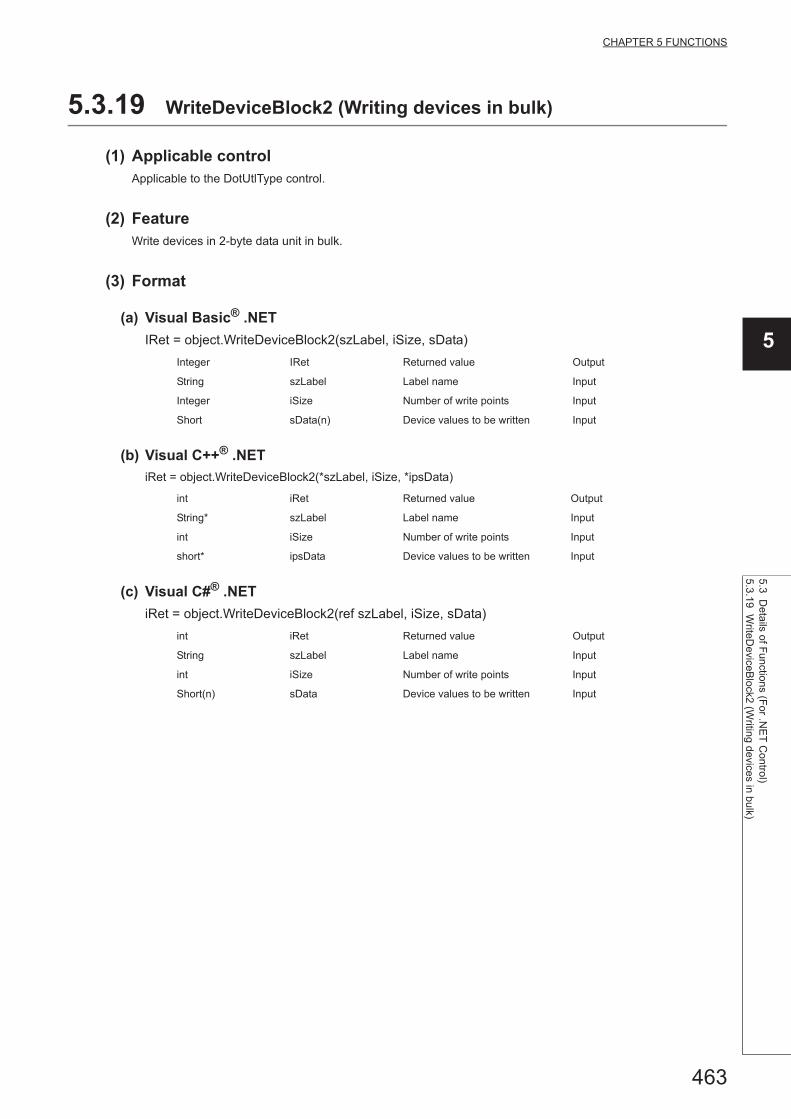
463
CHAPTER 5 FUNCTIONS
5
5.3 Details of F
unctions (For .N
ET
Control)
5.3.19 WriteD
eviceBlock2 (W
riting devices in bulk)
5.3.19 WriteDeviceBlock2 (Writing devices in bulk)
(1) Applicable controlApplicable to the DotUtlType control.
(2) FeatureWrite devices in 2-byte data unit in bulk.
(3) Format
(a) Visual Basic® .NET
IRet = object.WriteDeviceBlock2(szLabel, iSize, sData)
(b) Visual C++® .NET
iRet = object.WriteDeviceBlock2(*szLabel, iSize, *ipsData)
(c) Visual C#® .NET
iRet = object.WriteDeviceBlock2(ref szLabel, iSize, sData)
Integer IRet Returned value Output
String szLabel Label name Input
Integer iSize Number of write points Input
Short sData(n) Device values to be written Input
int iRet Returned value Output
String* szLabel Label name Input
int iSize Number of write points Input
short* ipsData Device values to be written Input
int iRet Returned value Output
String szLabel Label name Input
int iSize Number of write points Input
Short(n) sData Device values to be written Input

464
(4) Description • The devices for the amount specified for iSize (number of write points) are written in bulk starting from the
device specified for szLabel (label name).
• Store the device values to be written in sData (ipsData).
• For sData (ipsData), reserve arrays for more than the amount specified for iSize.
(5) How to specify devicesThe following describes how to specify label names and device values to be written.
• The following data type can be specified for label name.
*1 : The maximum number of characters that can be specified is 32 + NULL
• Set the following values for the number of write points according to the label data type.
Type class Label data type Label name format
Array
Label name
Member
Bit, Word, Double Word,
Float (Single Precision), Float (Double Precision),
String*1, String (Unicode)*1, Time,
Timer, Long timer,
Counter, Long counter,
Retentive Timer, Long retentive timer
Label name [number of elements]
Label name [n1] [n2] [n3]
Label (array) data typeNumber of
applicable wordsNumber of write points to be specified
Bit 1 Number of label array elements divided by 16 (rounded up)
Word 1 Number of label array elements
Double Word, Float (Single Precision) 2 Number of label array elements multiplied by 2
Float (Double Precision) 4 Number of label array elements multiplied by 4
String 17 Number of label array elements multiplied by 17
String (Unicode) 33 Number of label array elements multiplied by 33
Time 2 Number of label array elements multiplied by 2
Timer, Long timer,
Counter, Long counter,
Retentive Timer, Long retentive timer
1 Number of label array elements

465
CHAPTER 5 FUNCTIONS
5
5.3 Details of F
unctions (For .N
ET
Control)
5.3.19 WriteD
eviceBlock2 (W
riting devices in bulk)
• Set the device values to be written as follows.
<When bit device is specified> <When word device is specified>
Example: Write 3 points of data (3 words = 48 bits) to the
devices starting from M0.
• Label setting (Data type: Bit, Number of array elements:
48)
• Number of write points: 3
• Device values to be written
*2 : Devices are stored from the lower bit in the order of device number.
Example: Write 3 points of data to the devices starting
from D0.
• Label setting (Data type: Word, Number of array
elements: 3)
• Number of write points: 3
• Device values to be written
<When FXCPU devices of CN200 and later are specified> <When FD device is specified (4-word device)>
Example: Write 6 points of data to the devices starting
from CN200.*3
• Label setting (Data type: Double Word, Number of array
elements: 3)
• Number of write points: 6
• Device values to be written
*3 : For FXCPU devices of CN200 and later, 2 points of data are written to each 1 point of device (upper (H) and lower (L) data).Writing only 1 point of data will result in an error.
Example: Write 8 points of data to the devices starting
from FD0.
• Label setting (Data type: Double Word, Number of array
elements: 2)
• Number of write points: 8
• Device values to be written
Data type Device
Bit (0..47) M0
2 Bytes
M0 to M15*2
M16 to M31*2
M32 to M47*2
Data type Device
Word (0..2) D0
2 Bytes
D0
D1
D2
Data type Device
Double Word (0..2) CN200
2 Bytes
L of CN200
H of CN200
L of CN201
H of CN201
L of CN202
H of CN202
Data type Device
Double Word (0..1) FD0
2 Bytes
LL of FD0
LH of FD0
HL of FD0
HH of FD0
LL of FD1
LH of FD1
HL of FD1
HH of FD1

466
(6) Returned valueNormal termination : 0 is returned.
Abnormal termination: Any value other than 0 is returned. (Page 516, CHAPTER 7 ERROR CODES)
● The maximum number of write points should be the value which satisfies the following condition.Write starting device number + Number of write points Last device number
● When specifying bit type array labels, 0 or a multiple of 16 can be specified as a device number.
● For the number of write points, specify the number of words which applies to the data type specified for the label name. For the device values to be written, reserve a memory area for the number of points specified for the number of write points. If the memory area is not reserved, a critical error (an application error or the like) may occur.
● When a device which corresponds to the label name does not exist, an error occurs and data cannot be written.When any one of devices which correspond to multiple label names does not exist, an error occurs and data cannot be written.
● Digit specified bit device and index setting cannot be used.
● WriteDeviceBlock2 cannot be used for writing long timer device (LT) and retentive long timer device (LST).Use WriteDeviceRandom2 or SetDevice2.
<When label is Double Word array and word device is
specified>
Example: Write 6 points of data to the devices starting
from D100.
• Label setting (Data type: Double Word, Number of array
elements: 3)
• Number of write points: 6
• Device values to be written
Data type Device
Double Word (0..2) D100
2 Bytes
D100
D101
D102
D103
D104
D105

467
CHAPTER 5 FUNCTIONS
5
5.3 Details of F
unctions (For .N
ET
Control)
5.3.20 ReadD
eviceRandom
2 (Reading devices random
ly)
5.3.20 ReadDeviceRandom2 (Reading devices randomly)
(1) Applicable controlApplicable to the DotUtlType control.
(2) FeatureRead devices in 2-byte data unit randomly.
(3) Format
(a) Visual Basic® .NET
IRet = object.ReadDeviceRandom2(szLabel, iSize, sData(0))
IRet = object.ReadDeviceRandom2(szLabelList, iSize, sData(0))
(b) Visual C++® .NET
iRet = object.ReadDeviceRandom2(*szLabel, iSize, *arrsData)
iRet = object.ReadDeviceRandom2(**szLabelList, iSize, *arrsData)
(c) Visual C#® .NET
iRet = object.ReadDeviceRandom2(ref szLabel, iSize, ref sData)
iRet = object.ReadDeviceRandom2(ref szLabelList, iSize, ref sData)
Integer IRet Returned value Output
String szLabel Label name Input
Integer iSize Number of read points Input
Short sData(n) Read device values Output
Integer IRet Returned value Output
String szLabelList(n) Label list Input
Integer iSize Number of read points Input
Short sData(n) Read device values Output
Int iRet Returned value Output
String* szLabel Label name Input
int iSize Number of read points Input
short* arrsData Read device values Output
Int iRet Returned value Output
String** szLabelList Label list Input
int iSize Number of read points Input
short* arrsData Read device values Output
int iRet Returned value Output
String szLabel Label name Input
int iSize Number of read points Input
short(n) sData Read device values Output
int iRet Returned value Output
System.String() szLabelList Label list Input
int iSize Number of read points Input
short(n) sData Read device values Output
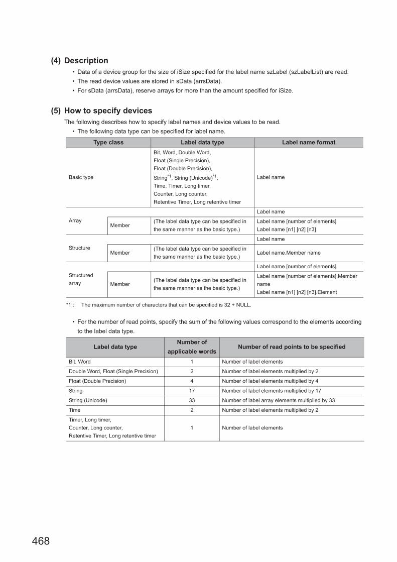
468
(4) Description • Data of a device group for the size of iSize specified for the label name szLabel (szLabelList) are read.
• The read device values are stored in sData (arrsData).
• For sData (arrsData), reserve arrays for more than the amount specified for iSize.
(5) How to specify devicesThe following describes how to specify label names and device values to be read.
• The following data type can be specified for label name.
*1 : The maximum number of characters that can be specified is 32 + NULL.
• For the number of read points, specify the sum of the following values correspond to the elements according
to the label data type.
Type class Label data type Label name format
Basic type
Bit, Word, Double Word,
Float (Single Precision),
Float (Double Precision),
String*1, String (Unicode)*1,
Time, Timer, Long timer,
Counter, Long counter,
Retentive Timer, Long retentive timer
Label name
Array
Label name
Member(The label data type can be specified in
the same manner as the basic type.)
Label name [number of elements]
Label name [n1] [n2] [n3]
Structure
Label name
Member(The label data type can be specified in
the same manner as the basic type.)Label name.Member name
Structured
array
Label name [number of elements]
Member(The label data type can be specified in
the same manner as the basic type.)
Label name [number of elements].Member
name
Label name [n1] [n2] [n3].Element
Label data typeNumber of
applicable wordsNumber of read points to be specified
Bit, Word 1 Number of label elements
Double Word, Float (Single Precision) 2 Number of label elements multiplied by 2
Float (Double Precision) 4 Number of label elements multiplied by 4
String 17 Number of label elements multiplied by 17
String (Unicode) 33 Number of label array elements multiplied by 33
Time 2 Number of label elements multiplied by 2
Timer, Long timer,
Counter, Long counter,
Retentive Timer, Long retentive timer
1 Number of label elements

469
CHAPTER 5 FUNCTIONS
5
5.3 Details of F
unctions (For .N
ET
Control)
5.3.20 ReadD
eviceRandom
2 (Reading devices random
ly)
• The read device values are stored as follows.
<When bit device and word device are specified>
Example: Read data from each 1 point of M0 and D0.
• Label setting
• Number of read points: 2
• Read device values
*1 : The device to be read is 1 point of "M0", and "0" or "1" is stored for the device value.
<When FXCPU devices of CN200 and later are specified> <When FD device is specified (4-word device)>
Example: Read 3 points of data from the devices including
CN200.
• Label setting
• Number of read points: 3
• Read device values
*2 : Only lower 2 bytes are read. Data are not read from the specified device H (upper 2 bytes).
Example: Read 3 points of data from the devices including
FD0.
• Label setting
• Number of read points: 3
• Read device values
*3 : Only lower 2 bytes are read. Data are not read from the specified devices HH, HL, and LH (upper 6 bytes).
szLabelList Data type Device
[0] LABEL1 Bit M0
[1] LABEL2 Word D0
2 Bytes Applicable label
M0*1 LABEL1
D0 LABEL2
szLabelList Data type Device
[0] LABEL1 Word D0
[1] LABEL2 Double Word CN200
[2] LABEL3 Word D1
2 Bytes Applicable label
D0 LABEL1
L of CN200*2 LABEL2
D1 LABEL3
szLabelList Data type Device
[0] LABEL1 Word D0
[1] LABEL2 Double Word FD0
[2] LABEL3 Word D1
2 Bytes Applicable label
D0 LABEL1
LL of FD0*3 LABEL2
D1 LABEL3

470
<When data type equivalent to 2 words or more is
specified for label><When array type label is specified>
Example: Write data by specifying labels of Double Word,
Float (Single Precision), Float (Double Precision), String*4,
and Time types.
• Label setting
• Number of read points: 27
• Read device values
*4 : The number of points of characters to be read is 17 (32 characters + NULL). The characters need to be converted in a user program because the characters of String type are not converted.
Example: Read data from the devices by specifying array
type labels.
• Label setting
• Number of read points: 8
• Read device values
szLabelList Data type Device
[0] LABEL1 Double Word D0
[1] LABEL2Float (Single
Precision)D100
[2] LABEL3Float (Double
Precision)D200
[3] LABEL4 String D300
[4] LABEL5 Time D400
2 BytesApplicable
label
D0LABEL1
D1
D100LABEL2
D101
D200
LABEL3D201
D202
D203
D300
:
D316*4
LABEL4
D400LABEL5
D401
szLabelList Data type Device
[0] LABEL1 Bit (0..1) M0
[1] LABEL2 Double Word (0..1) CN200
[2] LABEL3 Double Word (0..1) D0
2 BytesApplicable
label
M0 LABEL1[0]
M1 LABEL1[1]
L of CN200 LABEL2[0]
L of CN201 LABEL2[1]
D100LABEL3[0]
D101
D102LABEL3[1]
D103

471
CHAPTER 5 FUNCTIONS
5
5.3 Details of F
unctions (For .N
ET
Control)
5.3.20 ReadD
eviceRandom
2 (Reading devices random
ly)
(6) Returned valueNormal termination : 0 is returned.
Abnormal termination: Any value other than 0 is returned. (Page 516, CHAPTER 7 ERROR CODES)
● The maximum number of read points is 0x7FFFFFFF.
● For the number of read points, specify the number of words which applies to the data type specified for the label name. For the read device values, reserve a memory area for the number of points specified for the number of read points. If the memory area is not reserved, a critical error (an application error or the like) may occur.
● When a device which corresponds to the label name does not exist, an error occurs and data cannot be read.When any one of devices which correspond to multiple label names does not exist, an error occurs and data cannot be read.
● When a Double Word device is specified, only the data of the lower 1 word (2 bytes) are stored using this function. (An error does not occur.) When reading data from a Double Word device, use the ReadDeviceRandom function or the ReadDeviceBlock2 function.
● Digit specified bit device and index setting cannot be used.
<When structure type labels are specified><When labels with combined structure and label are
specified>
Example: Read data from the devices by specifying
structure type labels.
• Structure setting
• Label setting
• Number of read points: 6
• Read device values
*5 : Data of two devices are read when the device of CN200 and later is specified for the Double Word type label.
Example: Read data from the devices by specifying
structure type array and structure array type label.
• Structure setting
• Label setting
• Number of read points: 9
• Read device values
Structure
name
Label
nameData type
STRUCTL1 Bit
L2 Double Word
szLabelListData
type
Label
nameDevice
[0] LABEL1 STRUCTL1 D0.0
L2 D0
[1] LABEL2 STRUCTL1 M10
L2 CN200
2 BytesApplicable
label
D0.0 LABEL1.L1
D0LABEL1.L2
D1
M0 LABEL2.L1
L of CN200LABEL2.L2
L of CN201*5
Structure
name
Label
nameData type
STRUCT1L1 Bit
L2 Word
STRUCT2L1 Bit (0..2)
L2 Double Word
szLabelListData
type
Label
nameDevice
[0] LABEL1STRUCT1
(0..1)
L1 X0
L2 D0
[1] LABEL2 STRUCT2L1 M0
L2 D100
2 BytesApplicable
label
X0 LABEL1[0].L1
D0 LABEL1[0].L2
X1 LABEL1[1].L1
D1 LABEL1[1].L2
M0 LABEL2.L1[0]
M1 LABEL2.L1[1]
M2 LABEL2.L1[2]
D100LABEL2.L2
D101

472
5.3.21 WriteDeviceRandom2 (Writing devices randomly)
(1) Applicable controlApplicable to the DotUtlType control.
(2) FeatureWrite devices in 2-byte data unit randomly.
(3) Format
(a) Visual Basic® .NET
Ret = object.WriteDeviceRandom2(szLabel, iSize, sData(0))
Ret = object.WriteDeviceRandom2(szLabelList, iSize, sData(0))
(b) Visual C++® .NET
iRet = object.WriteDeviceRandom2(*szLabel, iSize, *arrsData)
iRet = object.WriteDeviceRandom2(**szLabelList, iSize, *arrsData)
(c) Visual C#® .NET
iRet = object.WriteDeviceRandom2(ref szLabel, iSize, sData)
iRet = object.WriteDeviceRandom2(ref szLabelList, iSize, sData)
Integer IRet Returned value Output
String szLabel Label name Input
Integer iSize Number of write points Input
Short sData(n) Device values to be written Input
Integer IRet Returned value Output
String szLabelList(n) Label list Input
Integer iSize Number of write points Input
Short sData(n) Device values to be written Input
int iRet Returned value Output
String* szLabel Label name Input
int iSize Number of write points Input
short* arrsData Device values to be written Input
int iRet Returned value Output
String** szLabelList Label list Input
int iSize Number of write points Input
short* arrsData Device values to be written Input
int iRet Returned value Output
String szLabel Label name Input
int iSize Number of write points Input
short(n) sData Device values to be written Input
int iRet Returned value Output
System.String() szLabelList Label list Input
int iSize Number of write points Input
short(n) sData Device values to be written Input

473
CHAPTER 5 FUNCTIONS
5
5.3 Details of F
unctions (For .N
ET
Control)
5.3.21 WriteD
eviceRandom
2 (Writing d
evices randomly)
(4) Description • Data of a device group for the size of iSize specified for the label name szLabel are written.
• Store the device values to be written in sData (arrsData).
• For sData (arrsData), reserve arrays for more than the amount specified for iSize.
(5) How to specify devicesThe following describes how to specify label names and device values to be written.
• The following data types can be specified for label names.
*1 : The maximum number of characters that can be specified is 32 + NULL.
• For the number of write points, specify the sum of the following values correspond to the elements according
to the label data type.
Type class Label data type Label name format
Basic type
Bit, Word, Double Word,
Float (Single Precision),
Float (Double Precision),
String*1, String (Unicode)*1, Time,
Timer, Long timer,
Counter, Long counter,
Retentive Timer, Long retentive timer
Label name
Array
Label name
Member(The label data type can be specified in
the same manner as the basic type.)
Label name [number of elements]
Label name [n1] [n2] [n3]
Structure
Label name
Member(The label data type can be specified in
the same manner as the basic type.)Label name.Member name
Structured
array
Label name [number of elements]
Member(The label data type can be specified in
the same manner as the basic type.)
Label name [number of elements].Member
name
Label name [n1] [n2] [n3].Element
Label data typeNumber of
applicable wordsNumber of write points to be specified
Bit, Word 1 Number of label elements
Double Word, Float (Single Precision) 2 Number of label elements multiplied by 2
Float (Double Precision) 4 Number of label elements multiplied by 4
String 17 Number of label elements multiplied by 17
String (Unicode) 33 Number of label array elements multiplied by 33
Time 2 Number of label elements multiplied by 2
Timer, Long timer,
Counter, Long counter,
Retentive Timer, Long retentive timer
1 Number of label elements

474
• Set the device values to be written as follows.
<When bit device and word device are specified>
Example: Write data to each 1 point of M0 and D0.
• Label setting
• Number of write points: 2
• Device values to be written
*1 : The device to be written is 1 point of "M0", and the value of least significant bit of 2 byte-data to be set is the device value to be written.
<When FXCPU devices of CN200 and later are specified> <When FD device is specified (4-word device)>
Example: Write 3 points of data to the devices including
CN200.*2
• Label setting
• Number of write points: 3
• Device values to be written
*2 : 4 bytes are written as 1 point for FXCPU devices of CN200 and later. Only lower 2 bytes can be set. "0" is written to the specified device H (upper 2 bytes).
Example: Write 3 points of data to the devices including
FD0.
• Label setting
• Number of write points: 3
• Device values to be written
*3 : Only lower 2 bytes can be set. "0" is written to the specified devices HH, HL, and LH (upper 6 bytes).
szLabelList Data type Device
[0] LABEL1 Bit M0
[1] LABEL2 Word D0
2 Bytes
M0*1
D0
szLabelList Data type Device
[0] LABEL1 Word D0
[1] LABEL2 Double Word CN200
[2] LABEL3 Word D1
2 BytesApplicable
label
D0 LABEL1
L of CN200 LABEL2
D1 LABEL3
szLabelList Data type Device
[0] LABEL1 Word D0
[1] LABEL2 Double Word FD0
[2] LABEL3 Word D1
2 BytesApplicable
label
D0 LABEL1
LL of FD0*3 LABEL2
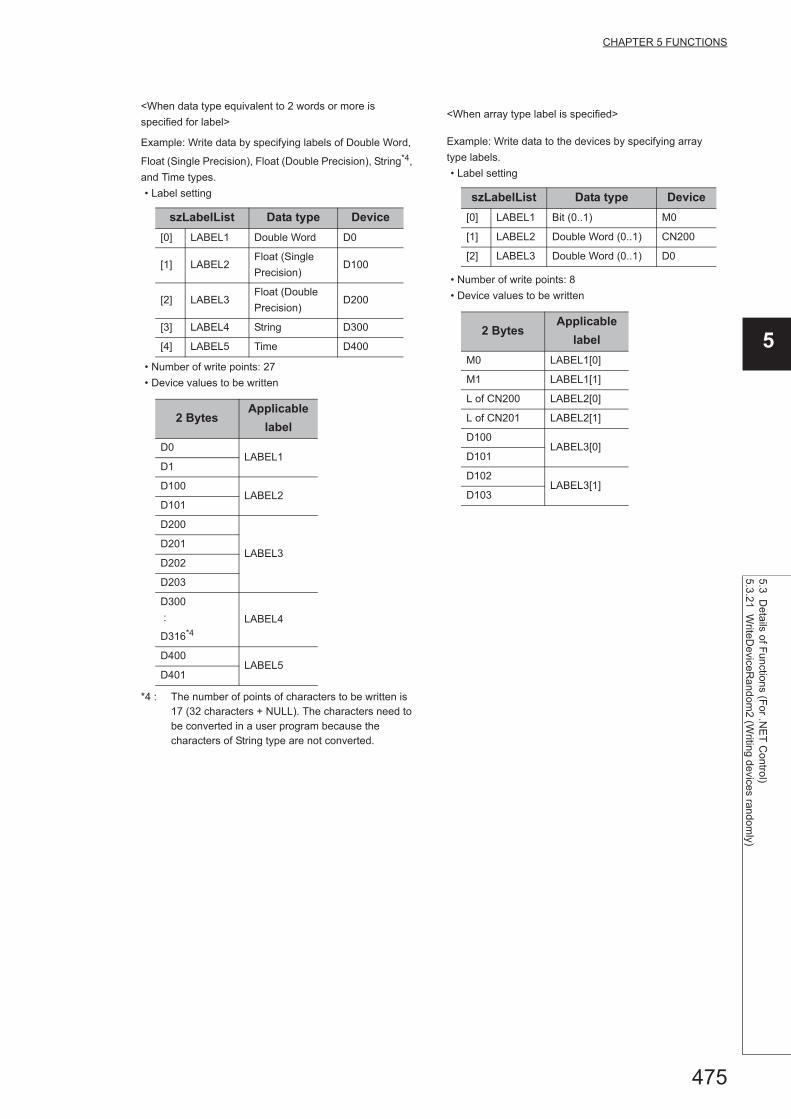
475
CHAPTER 5 FUNCTIONS
5
5.3 Details of F
unctions (For .N
ET
Control)
5.3.21 WriteD
eviceRandom
2 (Writing d
evices randomly)
<When data type equivalent to 2 words or more is
specified for label><When array type label is specified>
Example: Write data by specifying labels of Double Word,
Float (Single Precision), Float (Double Precision), String*4,
and Time types.
• Label setting
• Number of write points: 27
• Device values to be written
*4 : The number of points of characters to be written is 17 (32 characters + NULL). The characters need to be converted in a user program because the characters of String type are not converted.
Example: Write data to the devices by specifying array
type labels.
• Label setting
• Number of write points: 8
• Device values to be written
szLabelList Data type Device
[0] LABEL1 Double Word D0
[1] LABEL2Float (Single
Precision)D100
[2] LABEL3Float (Double
Precision)D200
[3] LABEL4 String D300
[4] LABEL5 Time D400
2 BytesApplicable
label
D0LABEL1
D1
D100LABEL2
D101
D200
LABEL3D201
D202
D203
D300
:
D316*4
LABEL4
D400LABEL5
D401
szLabelList Data type Device
[0] LABEL1 Bit (0..1) M0
[1] LABEL2 Double Word (0..1) CN200
[2] LABEL3 Double Word (0..1) D0
2 BytesApplicable
label
M0 LABEL1[0]
M1 LABEL1[1]
L of CN200 LABEL2[0]
L of CN201 LABEL2[1]
D100LABEL3[0]
D101
D102LABEL3[1]
D103

476
(6) Returned valueNormal termination : 0 is returned.
Abnormal termination: Any value other than 0 is returned. (Page 516, CHAPTER 7 ERROR CODES)
● The maximum number of write points is 0x7FFFFFFF.
● For the number of write points, specify the number of words which applies to the data type specified for the label name. For the device values to be written, reserve a memory area for the number of points specified for the number of write points. If the memory area is not reserved, a critical error (an application error or the like) may occur.
● When a device which corresponds to the label name does not exist, an error occurs and data cannot be written.When any one of devices which correspond to multiple label names does not exist, an error occurs and data cannot be written.
● When a Double Word device is specified, this function writes data of lower 1 word (2 bytes), and "0" is written to data of upper 1 word (2 bytes).When writing Double Word devices, use the WriteDeviceRandom or the WriteDeviceBlock2 function.
● Digit specified bit device and index setting cannot be used.
● If a Q motion CPU is accessed, an error is returned.
<When structure type labels are specified><When labels with combined structure and label are
specified>
Example: Write data to the devices by specifying structure
type labels.
• Structure setting
• Label setting
• Number of write points: 5
• Device values to be written
Example: Write data to the devices by specifying structure
type array and structure array type label.
• Structure setting
• Label setting
• Number of write points: 9
• Device values to be written
Structure
name
Label
nameData type
STRUCTL1 Bit
L2 Double Word
szLabelListData
type
Label
nameDevice
[0] LABEL1 STRUCTL1 D0.0
L2 D0
[1] LABEL2 STRUCTL1 M10
L2 CN200
2 BytesApplicable
label
D0.0 LABEL1.L1
D0LABEL1.L2
D1
M0 LABEL2.L1
L of CN200 LABEL2.L2
X1 LABEL3.L1
M0 to 15 LABEL3.L2
Structure
name
Label
nameData type
STRUCT1L1 Bit
L2 Word
STRUCT2L1 Bit (0..2)
L2 Double Word
szLabelListData
type
Label
nameDevice
[0] LABEL1STRUCT1
(0..1)
L1 X0
L2 D0
[1] LABEL2 STRUCT2L1 M0
L2 D100
2 BytesApplicable
label
X0 LABEL1[0].L1
D0 LABEL1[0].L2
X1 LABEL1[1].L1
D1 LABEL1[1].L2
M0 LABEL2.L1[0]
M1 LABEL2.L1[1]
M2 LABEL2.L1[2]
D100LABEL2.L2
D101
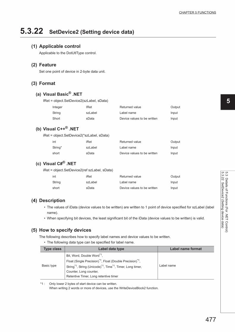
477
CHAPTER 5 FUNCTIONS
5
5.3 Details of F
unctions (For .N
ET
Control)
5.3.22 Se
tDevice2 (S
etting device data)
5.3.22 SetDevice2 (Setting device data)
(1) Applicable controlApplicable to the DotUtlType control.
(2) FeatureSet one point of device in 2-byte data unit.
(3) Format
(a) Visual Basic® .NET
IRet = object.SetDevice2(szLabel, sData)
(b) Visual C++® .NET
iRet = object.SetDevice2(*szLabel, sData)
(c) Visual C#® .NET
iRet = object.SetDevice2(ref szLabel, sData)
(4) Description • The values of iData (device values to be written) are written to 1 point of device specified for szLabel (label
name).
• When specifying bit devices, the least significant bit of the iData (device values to be written) is valid.
(5) How to specify devicesThe following describes how to specify label names and device values to be written.
• The following data type can be specified for label name.
*1 : Only lower 2 bytes of start device can be written.When writing 2 words or more of devices, use the WriteDeviceBlock2 function.
Integer IRet Returned value Output
String szLabel Label name Input
Short sData Device values to be written Input
int iRet Returned value Output
String* szLabel Label name Input
short sData Device values to be written Input
int iRet Returned value Output
String szLabel Label name Input
short sData Device values to be written Input
Type class Label data type Label name format
Basic type
Bit, Word, Double Word*1,
Float (Single Precision)*1, Float (Double Precision)*1,
String*1, String (Unicode)*1, Time*1, Timer, Long timer,
Counter, Long counter,
Retentive Timer, Long retentive timer
Label name
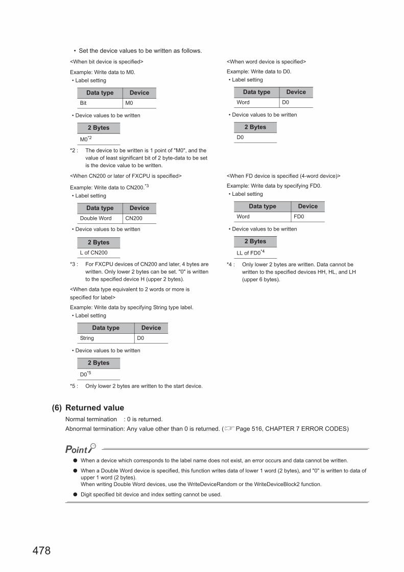
478
• Set the device values to be written as follows.
(6) Returned valueNormal termination : 0 is returned.
Abnormal termination: Any value other than 0 is returned. (Page 516, CHAPTER 7 ERROR CODES)
● When a device which corresponds to the label name does not exist, an error occurs and data cannot be written.
● When a Double Word device is specified, this function writes data of lower 1 word (2 bytes), and "0" is written to data of upper 1 word (2 bytes).When writing Double Word devices, use the WriteDeviceRandom or the WriteDeviceBlock2 function.
● Digit specified bit device and index setting cannot be used.
<When bit device is specified> <When word device is specified>
Example: Write data to M0.
• Label setting
• Device values to be written
*2 : The device to be written is 1 point of "M0", and the value of least significant bit of 2 byte-data to be set is the device value to be written.
Example: Write data to D0.
• Label setting
• Device values to be written
<When CN200 or later of FXCPU is specified> <When FD device is specified (4-word device)>
Example: Write data to CN200.*3
• Label setting
• Device values to be written
*3 : For FXCPU devices of CN200 and later, 4 bytes are written. Only lower 2 bytes can be set. "0" is written to the specified device H (upper 2 bytes).
Example: Write data by specifying FD0.
• Label setting
• Device values to be written
*4 : Only lower 2 bytes are written. Data cannot be written to the specified devices HH, HL, and LH (upper 6 bytes).
<When data type equivalent to 2 words or more is
specified for label>
Example: Write data by specifying String type label.
• Label setting
• Device values to be written
*5 : Only lower 2 bytes are written to the start device.
Data type Device
Bit M0
2 Bytes
M0*2
Data type Device
Word D0
2 Bytes
D0
Data type Device
Double Word CN200
2 Bytes
L of CN200
Data type Device
Word FD0
2 Bytes
LL of FD0*4
Data type Device
String D0
2 Bytes
D0*5

479
CHAPTER 5 FUNCTIONS
5
5.3 Details of F
unctions (For .N
ET
Control)
5.3.23 GetD
evice2 (Acquirin
g device data)
5.3.23 GetDevice2 (Acquiring device data)
(1) Applicable controlApplicable to the DotUtlType control.
(2) FeatureAcquire one point of device in 2-byte data unit.
(3) Format
(a) Visual Basic® .NET
IRet = object.GetDevice2(szLabel, sData)
(b) Visual C++® .NET
iRet = object.GetDevice2(*szLabel, *lpsData)
(c) Visual C#® .NET
iRet = object.GetDevice2(ref szLabel, ref sData)
(4) DescriptionOne point of device data specified for szLabel (label name) is stored in sData (lpsData) (read device values).
(5) How to specify devicesThe following describes how to specify label names and device values to be read.
• The following data type can be specified for label name.
*1 : Only lower 2 bytes of start device can be read.When reading 2 words or more of devices, use the ReadDeviceBlock2 function.
Integer IRet Returned value Output
String szLabel Label name Input
Short sData Read device values Output
int iRet Returned value Output
String* szLabel Label name Input
short* lpsData Read device values Output
int iRet Returned value Output
String szLabel Label name Input
short sData Read device values Output
Type class Label data type Label name format
Basic type
Bit, Word, Double Word*1,
Float (Single Precision)*1, Float (Double Precision)*1,
String*1, String (Unicode)*1, Time*1, Timer, Long timer,
Counter, Long counter,
Retentive Timer, Long retentive timer
Label name

480
• The read device values are stored as follows.
(6) Returned valueNormal termination : 0 is returned.
Abnormal termination: Any value other than 0 is returned. (Page 516, CHAPTER 7 ERROR CODES)
● When a device which corresponds to the label name does not exist, an error occurs and data cannot be read.
● For the read device values, reserve 2 bytes of memory area. If the memory area is not reserved, a critical error (an application error or the like) may occur.
● When a Double Word device is specified, only the data of the lower 1 word (2 bytes) are stored using this function. (An error does not occur.) When reading data from a Double Word device, use the ReadDeviceRandom function or the ReadDeviceBlock2 function.
● Digit specified bit device and index setting cannot be used.
<When bit device is specified> <When word device is specified>
Example: Read data from M0.
• Label setting
• Read device values
*2 : The device to be read is 1 point of "M0", and "0" or "1" is stored for the device value.
Example: Read data from D0.
• Label setting
• Read device values
<When CN200 or later of FXCPU is specified> <When FD device is specified (4-word device)>
Example: Read data from CN200.*3
• Label setting
• Read device values
*3 : The specified device H (lower 2 bytes) is read as 1 point for FXCPU devices of CN200 and later.Data are not read from the specified device H (upper 2 bytes).
Example: Read data by specifying FD0.
• Label setting
• Read device values
*4 : Only lower 2 bytes are read. Data are not read from the specified devices HH, HL, and LH (upper 6 bytes).
<When data type equivalent to 2 words or more is specified
for label>
Example: Read data by specifying String type label.
• Label setting
• Read device values
*5 : Only lower 2 bytes are read to the start device.
Data type Device
Bit M0
2 Bytes
M0*2
Data type Device
Word D0
2 Bytes
D0
Data type Device
Double Word CN200
2 Bytes
L of CN200
Data type Device
Word FD0
2 Bytes
LL of FD0*4
Data type Device
String D0
2 Bytes
D0*5

481
CHAPTER 5 FUNCTIONS
5
5.3 Details of F
unctions (For .N
ET
Control)
5.3.24 Connect (C
onnecting te
lephone line)
5.3.24 Connect (Connecting telephone line)
(1) Applicable controlApplicable to the DotUtlType control.
(2) FeatureConnect the telephone line.
(3) Format
(a) Visual Basic® .NET
IRet = object.Connect()
(b) Visual C++® .NET
iRet = object.Connect()
(c) Visual C#® .NET
iRet = object.Connect()
(4) Description • The telephone line is connected according to the property settings of the modem communication control.
• When routing a serial communication module, the telephone line is connected in the connection system set
in the ActConnectWay property.
When auto line connect (callback number specification), callback connect (number specification), or callback
request (number specification) is set in the ActConnectWay property, an error occurs if a number is not set in
the ActCallbackNumber property.
(5) Returned valueNormal termination : 0 is returned.
Abnormal termination: Any value other than 0 is returned. (Page 516, CHAPTER 7 ERROR CODES)
(6) Considerations for executing the Connect function • Always connect the telephone line before the execution of the Open function.
• When disconnecting the telephone line, execute the Disconnect function.
During the execution of the Connect function, the telephone line remains connected even when the Open
and Close functions are executed repeatedly.
• If the telephone line is disconnected in the Open status for some reason, always execute the Close function
before reconnecting the telephone line.
Integer IRet Returned value Output
int iRet Returned value Output
int iRet Returned value Output

482
(7) Considerations when using multiple telephone line connection objects • When control types, port numbers, and telephone numbers of controls are different
When control types, port numbers, and telephone numbers set to multiple controls are different, an error
(error code: 0xF1000016) occurs if the Connect function is executed to connect the control whose port
number and telephone number are different from those of the control which executed the Connect function
first.
• When port numbers and telephone numbers of controls are the same
When control types, port numbers, and telephone numbers set to multiple controls are the same, the
termination status are different according to the connection system of the callback function.
The following table shows the relations between the connection system and the termination status of the
callback function.
: Normal termination : Abnormal termination (Error occurrence)
Connection system of control
which executed the Connect
function first
Connection system of control which executed the Connect function second or Later
Auto line connect
Auto line connect(Callback
fixation)
Auto line connect (Callback
number specification)
Callback connect
(Fixation)
Callback connect
(Number
specification)
Callback request
(Fixation)
Callback request
(Number
specification)
Callback
reception
waiting
Auto line connect
Auto line connect (Callback
fixation)
Auto line connect (Callback
number specification)
Callback connect (Fixation)
Callback connect (Number
specification)
Callback request (Fixation)
Callback request (Number
specification)
Callback reception waiting

483
CHAPTER 5 FUNCTIONS
5
5.3 Details of F
unctions (For .N
ET
Control)
5.3.25 Disconnect (D
isconnecting telephone line)
5.3.25 Disconnect (Disconnecting telephone line)
(1) Applicable controlApplicable to the DotUtlType control.
(2) FeatureDisconnect the telephone line.
(3) Format
(a) Visual Basic® .NET
IRet = object.Disconnect()
(b) Visual C++® .NET
iRet = object.Disconnect()
(c) Visual C#® .NET
iRet = object.Disconnect()
(4) DescriptionThe telephone line that was connected using the Connect function is disconnected.
(5) Returned valueNormal termination : 0 is returned.
Abnormal termination: Any value other than 0 is returned. (Page 516, CHAPTER 7 ERROR CODES)
Integer IRet Returned value Output
int iRet Returned value Output
int iRet Returned value Output

484
(6) Considerations for executing the Disconnect function • When executing the Disconnect function during the execution of the Open function, execute the Close
function before executing the Disconnect function.
• If the telephone line is disconnected in the Open status for some reason, always execute the Close function
before reconnecting the telephone line.
• When multiple telephone line connection objects are used, execute the Disconnect function on the object
which executed the Connect function first after executing the Disconnect function on other objects.
When multiple telephone line connection objects are used, the telephone line is not disconnected if the
Disconnect function is not executed on the object that executed the Connect function first.
The following figure shows the example of how to use multiple objects simultaneously.
<Object A>
Example: When using two controls simultaneously
(Including the case when the objects A and B are operated by different applications)
Connection start
Execution of the Connect function
Execution of the Open function
Execution of the Close function
Complete
Execution of the Disconnect function*1
Execution of the function such as
the ReadDeviceBlock function
Execution of the Connect function
Execution of the Open function
Execution of the Close function
Complete
Execution of the Disconnect function
Execution of the function such as
the ReadDeviceBlock function
Connection start
<Object B>
*1 : The actual telephone line is disconnected.
The Disconnect function on the object A does not
terminate normally if the Disconnection function is
not executed on the object B.
Te
lep
ho
ne
line
is c
on
ne
cte
d.

485
CHAPTER 5 FUNCTIONS
5
5.3 Details of F
unctions (For .N
ET
Control)
5.3.26 GetE
rrorMessage (R
eceiving error m
essage)
5.3.26 GetErrorMessage (Receiving error message)
(1) Applicable controlApplicable to the DotSupportMsg control.
(2) FeatureReceive the error description and its corrective action corresponding to the error code.
(3) Format
(a) Visual Basic® .NET
IRet = object.GetErrorMessage(IErrorCode, szErrorMessage)
(b) Visual C++® .NET
iRet = object.GetErrorMessage(iErrorCode, **lpszErrorMessage)
(c) Visual C#® .NET
iRet = object.GetErrorMessage(iErrorCode, ref szErrorMessage)
(4) Description • The error description and its corrective action of the error code specified for lErrorCode (iErrorCode) are
read.
• The read error description and its corrective action are stored in szErrorMessage (lpszErrorMessage).
(5) Returned valueNormal termination : 0 is returned.
Abnormal termination: Any value other than 0 is returned. (Page 516, CHAPTER 7 ERROR CODES)
Integer IRet Returned value Output
Integer IErrorCode Error code Input
String szErrorMessage Error message Output
int iRet Returned value Output
int iErrorCode Error code Input
String** lpszErrorMessage Error message Output
int iRet Returned value Output
int iErrorCode Error code Input
String szErrorMessage Error message Output
486
CHAPTER 6 SAMPLE PROGRAMS
This chapter explains the sample programs registered at the installation of MX Component.
(1) Sample programs, test programs, and sample sequence programs
(a) Sample programs and test programs
Sample programs are for references when creating user programs.
Test programs are for conducting communication tests.
Use the programs with your responsibility.
(b) Sample sequence programs
Sample sequence programs require modifications according to the system configuration and parameter
settings.
Modify the program to suit the system.
Use the programs with your responsibility.

487
CHAPTER 6 SAMPLE PROGRAMS
6
(2) List of sample programs, test programs, and sample sequence programsThe following table shows the list of sample programs registered under [user specified folder] - [Act] - [Samples]
when installing MX Component.
Folder name DescriptionSupported
languageReference
AccessVBASample Sample program for ActUtlType
VBA (Access)
Page 493,
Section 6.1.3
TestPro Test program for ActUtlType*1 –
ExcelVBA
Sample
Sample program for ActUtlType
VBA (Excel)
Page 489,
Section 6.1.1
Sample program for ActUtlType and
ActSupportMsg
(Reading/writing devices)
Page 491,
Section 6.1.2
TestProTest program for ActUtlType and
ActSupportMsg*1–
VBScript*2
SampleASP
Sample program for ActMLUtlType
HTML (ASP function)Page 497,
Section 6.3
SampleHTML
HTML
Page 495,
Section 6.2
TestProTest program for ActUtlType and
ActSupportMsg*1–
Vb.NET*3
ModemSampleModem communication sample program for
ActUtlType and ActSupportMsg
Visual Basic®.NET
Page 500,
Section 6.4.1
SampleRead/Write sample program for ActUtlType
and ActProgType
Page 502,
Section 6.4.2
SampleDot Read/Write sample program for DotUtlType
Sample_ReferencesRead/Write sample program for ActUtlType
and ActProgType
Sample_References
DotRead/Write sample program for DotUtlType
Sample_TypeConvType conversion sample program for
ActUtlType and ActSupportMsg
Page 505,
Section 6.4.3
*1 : A test program for checking operations.
*2 : The test programs will be operate with the following Internet Explorer®.
• Internet Explorer®8
• Internet Explorer®9
• Internet Explorer®10
• Internet Explorer®11
*3 : When the operation environment of the sample program is Visual Studio®2013, the installation of MFC library (DLL) for multiple byte character encode (MBCS) is required.

488
Folder name DescriptionSupported
language
Reference
Section
Vc.NET
Sample2005Read/Write sample program for ActUtlType
and ActProgTypeVisual C++®.NET
(Visual Studio® 2005)
Page 507,
Section 6.5.1
SampleDot2005 Read/Write sample program for DotUtlType
Sample2010Read/Write sample program for ActUtlType
and ActProgTypeVisual C++®.NET
(Visual Studio® 2010)SampleDot2010 Read/Write sample program for DotUtlType
Sample_References2005Read/Write sample program for ActUtlType
and ActProgTypeVisual C++®.NET
(Visual Studio® 2005)Sample_ReferencesDot2005 Read/Write sample program for DotUtlType
Sample_References2010Read/Write sample program for ActUtlType
and ActProgTypeVisual C++®.NET
(Visual Studio® 2010)Sample_ReferencesDot2010 Read/Write sample program for DotUtlType
Sample_Support For DotSupportMsgVisual C++®.NET
(Visual Studio® 2005)
Page 508,
Section 6.5.2
Vc
SampleENGRead/Write sample program for ActUtlType
and ActProgType
Visual C++®.NET(MFC)
(Visual Studio® 2005)
Page 511,
Section 6.7.1
CustomSampleENGRead/Write sample program for ActUtlType
and ActProgType
Page 513,
Section 6.7.2
Sample_SupportENG For ActSupportMsgPage 514,
Section 6.7.3
Vcs.NET*4
SampleRead/Write sample program for ActUtlType
and ActProgType
Visual C#®.NET
(Visual Studio® 2005)
Page 510,
Section 6.6.1
SampleDot Read/Write sample program for DotUtlType
Sample_ReferencesRead/Write sample program for ActUtlType
and ActProgType
Sample_ReferencesDot Read/Write sample program for DotUtlType
GppW
CCG4ASample ladder for CC-Link G4
communication
Sequence program
(GX Developer)
MX
Component
Version 4
Operating
Manual.
FXCPUtelSample ladder for modem communication
(FXCPU)
QJ71C24Callback
Sample ladder for modem communication
(Q series-compatible C24) in which the
setting 1 is specified for the callback function
QJ71C24Callback_Number
Sample ladder for modem communication
(Q series-compatible C24) in which the
setting 3 is specified for the callback function
QJ71C24TELSample ladder for modem communication
(Q series-compatible C24)
*4 : When the operation environment of the sample program is Visual Studio®2013, the installation of MFC library (DLL) for multiple byte character encode (MBCS) is required.

489
CHAPTER 6 SAMPLE PROGRAMS
6
6.1 VB
A S
ample P
rograms
6.1.1 Sam
ple program
for Excel
6.1 VBA Sample Programs
This section explains the VBA sample programs for Excel and Access.
6.1.1 Sample program for Excel
This sample program is a program to log and graph device values of a programmable controller CPU using the
ActUtlType control.
This sample program was created on Excel 2003.
(1) How to use the sample program
1. Open the sample sheet.
2. Enter the logical station number, which was specified for the communication setting in
Communication Setup Utility, into the "LogicalStationNumber" input cell.
3. Enter the start device of devices to be read into the "DeviceName" input cell.
4. Enter the logging interval into the "LoggingTiming" input cell.
5. Click the button to start logging.
When the logging starts, the past 10 device values and line graphs are displayed on the graph.
6. Click the button to stop logging.
Note that the logging data on the screen are not cleared.
7. If an error occurs during the process, an error message is displayed on the "Message" output cell
and an error code is displayed on the "Return Code" output cell. When an error occurs, perform
the troubleshooting corresponds to the error code.
(Page 516, CHAPTER 7 ERROR CODES)
(2) Considerations for using the sample program • Before executing the sample program, set the communication settings in Communication Setup Utility.
• When changing the input value, click the button to stop logging, change the input value, and
click the button to start logging.
• In this sample program, the number of device points to be logged is 10, and the number of logging times is
10.
(3) Sample fileThe sample program is installed in the following folder when the default pass is selected.
Folder name File name
[User specified folder] - [Act] - [Samples] - [ExcelVBA] - [Sample] Sample.xls

490
(4) ScreenThe following explains the settings on the sample program screen.
Item Description
LogicalStationNumberEnter the logical station number which was specified for the communication setting in
Communication Setup Utility.
DeviceName Enter the start device of devices to be read.
LoggingTiming (hh:mm:ss)
Enter the logging interval.
Example: Logging at an interval of 1 second 0:0:1
Logging at an interval of 1 hour 30 minutes 1:30:0
Message Display the function execution result. (Character string)
ReturnCode Display the function execution result. (Hexadecimal value)
Time Display the logged system time.
Data01 to 10 Display the logged device values.
Graph Display the past 10 logged values of 10 devices in line graphs.
button Start logging.
button Stop logging.

491
CHAPTER 6 SAMPLE PROGRAMS
6
6.1 VB
A S
ample P
rograms
6.1.2 Sam
ple program
for Exce
l (Reading
/writin
g devices)
6.1.2 Sample program for Excel (Reading/writing devices)
This sample program is a program to read/write the programmable controller CPU devices (D0 to D9) using the
ActUtlType control.
This program displays the error code and error message on the dialog box using the ActSupportMsg control when an
error occurs.
This sample program was created on Excel 2003.
(1) How to use the sample program
1. Open the sample sheet.
2. Enter the logical station number, which was specified for the communication setting in
Communication Setup Utility, into the "LogicalStationNumber" input cell.
3. Click the button to read the device values of D0 to D9 of the programmable controller
CPU and display them on the DeviceRead area.
4. Enter values into D0 to D9 of the DeviceWrite area and click the button to write the values
to D0 to D9 of the programmable controller CPU.
5. If reading/writing data from/to the devices D0 to D9 fails, the error message corresponds to the
error code is displayed on the dialog box.
(2) Considerations for using the sample programBefore executing the sample program, set the communication settings in Communication Setup Utility.
(3) Sample fileThe sample program is installed in the following folder when the default pass is selected.
Folder name File name
[User specified folder] - [Act] - [Samples] - [ExcelVBA] - [Sample] Sample_DeviceRW.xls

492
(4) ScreenThe following explains the settings on the sample program screen.
Item Description
LogicalStationNumberEnter the logical station number which was specified for the communication setting in
Communication Setup Utility.
(DeviceRead area) Display the device values of D0 to D9 of the programmable controller CPU.
(DeviceWrite area) Enter the values to be written into D0 to D9 of the programmable controller CPU.
buttonRead the device values of D0 to D9 of the programmable controller CPU and display them on
the DeviceRead area.
buttonWrite the device values entered into D0 to D9 of the DeviceWrite area to D0 to D9 of the
programmable controller CPU.
1 2

493
CHAPTER 6 SAMPLE PROGRAMS
6
6.1 VB
A S
ample P
rograms
6.1.3 Sam
ple program
for Access
6.1.3 Sample program for Access
This sample program is a program to log and monitor device values of a programmable controller CPU using the
ActUtlType control.
This sample program was created on Access 2003.
(1) How to use the sample program
1. Open the database.
2. Enter the logical station number, which was specified for the communication setting in
Communication Setup Utility, into the "LogicalStationNumber" text box.
3. Enter the logging interval into the "LoggingTiming" text box.
4. Click the button to start logging.
5. Click the button to stop logging.
Note that the logging data on the screen are not cleared.
6. If an error occurs during the process, an error message and error code are displayed on the
message box. When an error occurs, perform the troubleshooting corresponds to the error code.
(Page 516, CHAPTER 7 ERROR CODES)
(2) Considerations for using the sample program • Before executing the sample program, set the communication settings in Communication Setup Utility.
• When changing the input value, click the button to stop logging, change the input value, and click
the button to start logging.
• In this sample program, devices "D0" to "D4" are set as the devices to be monitored, and "D10" to "D17" are
set as the devices to be logged.
The monitoring interval is 1 second.
• This sample program logs device values up to 100 times.
If the number of logging times exceeds 100, the oldest logging data is deleted and the newest logging data is
registered.
(3) Sample fileThe sample program is installed in the following folder when the default pass is selected.
Folder name File name
[User specified folder] - [Act] - [Samples] - [AccessVBA] - [Sample] Sample.mdb

494
(4) ScreenThe following explains the settings on the sample program screen.
Item Description
LogicalStationNumberEnter the logical station number which was specified for the communication setting in
Communication Setup Utility.
LoggingTiming Enter the logging interval. (In seconds)
LoggingData Display the logged data.
OnDeviceStatus Display the devices whose conditions are satisfied among the devices being monitored.
button Start logging.
button Stop logging.

495
CHAPTER 6 SAMPLE PROGRAMS
6
6.2 VB
Script S
ample
Progra
m
6.2 VBScript Sample Program
This section explains the VBScript sample program.
This sample program is a program to define device values of a programmable controller CPU as a capacity and status
of a tank, and monitor their values using the ActUtlType control.
This sample program was created on Microsoft® FrontPage® 2000.
(1) How to use the sample program
1. Open the sample file to open the communication line to the programmable controller CPU.
2. The device values of the programmable controller CPU are acquired at an interval of 1 second and
they are used to display the capacity and status of the tank.
3. If an error occurs during the process, an error message and error code are displayed on the
message box. When an error occurs, perform the troubleshooting corresponds to the error code.
(Page 516, CHAPTER 7 ERROR CODES)
(2) Considerations for using the sample program • Before executing the sample program, set the logical station number to "0" for the communication setting in
Communication Setup Utility.
• In this sample program, the device "D100" is used for the tank capacity, and the device "D101" is used for
the tank status.
(3) Sample fileThe sample program is installed in the following folder when the default pass is selected.
Folder name File name
[User specified folder] - [Act] - [Samples] - [VBScript] - [SampleHTML] Sample.html

496
(4) ScreenThe following explains the settings on the sample program screen.
Tank capacity: Empty
Tank status: Normal
Tank capacity: Full
Tank status: Error
Item Description Remarks
Tank capacityIndicate the tank capacity.
(Within the range of 0 device value 200)Linked with the device "D100".
Tank status
Indicate the tank status.
Normal (device value = 0): Blue lamp ON
Error (device value <> 0): Red lamp ON
Linked with the device "D101".

497
CHAPTER 6 SAMPLE PROGRAMS
6
6.3 AS
P S
ample P
rograms
6.3 ASP Sample Programs
This sample program is a program to read programmable controller CPU data and device values using the ActUtlType
control.
(1) File structure • Sample.asp (data input screen)
The initial display screen used to set data for monitoring.
• SampleControl.asp (data acquisition screen)
Acquire input data of Sample.asp, store them in global variables, and check them for errors.
• SampleMon.asp (data display screen)
Display data according to input data of Sample.asp. Display an error description when an error occurs.
(2) How to use the sample program
1. Store Sample.asp, SampleControl.asp, and SampleMon.asp in the same folder on the WWW
server.
2. Browse the URL of Sample.asp on the Microsoft® Internet Explorer® and display the initial screen.
3. Enter data into "MonitorTiming", "LogicalStationNumber", "DeviceName", and "DeviceSize" on the
initial screen. Press the button to start the Open processing, ReadDeviceBlock
processing, GetCpuType processing, and Close processing.
4. The input data for "MonitorTiming:", "LogicalStationNumber:", "DeviceName:", and "DeviceSize:"
are displayed on the data display screen.
5. An error occurrence processing is displayed for "Message:" when an error occurs in the process.
6. The result of the process is displayed for "Return Code:".
7. The model of the connected programmable controller CPU is displayed for "CpuType:".
8. The device data of the connected programmable controller CPU is displayed for "ReadData(Hex)".
9. When an error occurs, perform the troubleshooting corresponds to the error code.
(Page 516, CHAPTER 7 ERROR CODES)
10. The data display screen repeats updating at the interval set for "MonitorTiming:".
11. Press the button to return to the initial screen.
(3) Considerations for using the sample program • Before executing the sample program, set the communication settings in Communication Setup Utility.
(4) Sample file listThe sample program is installed in the following folder when the default pass is selected.
Folder name File name
[User specified folder] - [Act] - [Samples] - [VBScript] - [SampleASP]
Sample-E.asp
SampleControl-E.asp
SampleMon-E.asp

498
(5) ScreenThe following explains the settings on the sample program screen.
(a) Data input screen (Sample-E.asp)
(b) Data acquisition screen (SampleControl-E.asp)
The data acquisition screen is a screen used to store the data entered on the data input screen into the global
variables and check them for errors. This screen is not displayed on the Internet Explorer® screen.
Item Description
MonitorTiming Enter the monitoring interval.
LogicalStationNumber Enter the logical station number.
DeviceName Enter the device name of the device to be read.
DeviceSize Enter the number of points of the devices to be read.
button Start the monitor processing.

499
CHAPTER 6 SAMPLE PROGRAMS
6
6.3 AS
P S
ample P
rograms
(c) Data display screen (SampleMon-E.asp)
Item Description
MonitorTiming: Display the monitoring interval.
LogicalStationNumber: Display the logical station number.
DeviceName: Display the device name of the device to be read.
DeviceSize: Display the number of points of the devices to be read.
Message: Display an error description at an error occurrence.
Return Code: Display the method execution result.
CpuType: Display the CPU model.
ReadData(Hex) Display the read device values.
button Return to the initial screen.

500
6.4 Visual Basic® .NET Sample Programs
6.4.1 Modem communication sample program
This sample program is a program to monitor devices of a programmable controller CPU corresponds to the specified
logical station number using the ActUtlType control.
This program displays the error code and error message on the dialog box using the ActSupportMsg control when an
error occurs.
This sample program was created on Visual Basic® .NET (Visual Studio® 2005).
(1) How to use the sample program
1. Enter the logical station number, which was specified for the modem communication setting in
Communication Setup Utility, into the "LogicalStationNumber" text box.
2. If a password is set to the module to be connected, enter the password into the "Password" text
box.
3. Enter the monitoring interval into the "MonitorInterval" text box.
4. Enter the device name to be monitored into the "DeviceName" text box, and the number of device
points into the "Size" text box.
5. Click the button to open the communication line after connecting the telephone line,
and read device values at the interval specified using the RedDeviceBlock function. (For the
logical station number that does not require the telephone line connection, the telephone line is
not connected and only the Open function is executed on the communication line.)
6. Click the button to disconnect the telephone line after closing the communication
line.
7. If an error occurs during the process of this sample program, an error code is displayed on the
"ReturnValue" text box. If the error code is displayed on the "ReturnValue" text box, click the
button to display the error description and corrective action corresponds to the
displayed error code.
When an error occurs, perform the troubleshooting corresponds to the error code.
(Page 516, CHAPTER 7 ERROR CODES)
(2) Considerations for using the sample program • Since the ActUtlType control is used, set the logical station number in Communication Setup Utility before
executing the sample program.
• When changing the logical station number, monitoring interval, device name, and number of read points,
click the button to close the communication line, and click the button to resume
the communication.

501
CHAPTER 6 SAMPLE PROGRAMS
6
6.4 Visu
al Basic
® .N
ET
Sam
ple Prog
rams
6.4.1 Mo
dem co
mm
unication sample program
(3) Sample fileThe sample program is installed in the following folder when the default pass is selected.
(4) ScreenThe following explains the settings on the sample program screen.
Folder name File name
[User specified folder] - [Act] - [Samples] - [Vb.NET] - [ModemSample] ModemSample.sln
Item Description
LogicalStationNumber Enter the logical station number set in Communication Setup Utility.
Password Enter the password when it is required.
MonitorInterval Set the monitoring interval. (In seconds)
DeviceName Enter the device name to be monitored.
Size Enter the number of read points.
ReturnValue Display the returned value of the executed method.
button Open the communication line and start monitoring after connecting the telephone line.
button Disconnect the telephone line and stop monitoring after closing the communication line.
buttonAcquire and display the error description and corrective action for the error code of
"ReturnValue".

502
6.4.2 Read/Write sample program
This sample program is a program to read/write device values of a programmable controller CPU and monitor device
status using any of the ActUtlType control, the DotUtlType control, or the ActProgType control.
This sample program was created on Visual Basic® .NET (Visual Studio® 2005).
(1) How to use the sample program
1. Load the form and select the control to be used.
2. When using the ActUtlType control, enter the logical number, which was specified for the
communication setting in Communication Setup Utility, into the "LogicalStationNumber" text box
before clicking the button.
3. Click the button to open the communication line.
4. For reading devices randomly, enter the device name and the number of points to be read into the
"DeviceName" and "DeviceSize" text boxes in the "Random Read/Write" frame, and click the
button to display the device data on the "Data" text box in the "Output" frame.
5. For writing devices randomly, enter the device name and the number of points to be written in the
"DeviceName" and "DeviceSize" text boxes in the "Random Read/Write" frame, enter the device
value to be written into the "DeviceData" text box inside the same frame, and click the
button to write the device value to the programmable controller CPU.
6. For reading devices in bulk, enter the device name and the number of points to be read into the
"DeviceName" and "DeviceSize" text boxes in the "Block Read/Write" frame, and click the
button to display the device data on the "Data" text box in the "Output" frame.
7. For writing devices in bulk, enter the device name and the number of points to be written into the
"DeviceName" and "DeviceSize" text boxes in the "Block Read/Write" frame, enter the device
value to be written into the "DeviceData" text box in the same frame, and click the
button to write the device value to the programmable controller CPU.
8. For registering devices for status monitoring, enter the device name, number of points, device
value and status monitoring interval into the "DeviceName", "DeviceSize", "DeviceData", and
"MonitorCycle" text boxes in the "Status Entry/Free" frame as the event occurrence conditions,
and click the button.
When the registered event occurrence conditions are satisfied, the event data are displayed on the
"Data" text box in the "Output" frame.
9. For deregistering registered devices for status monitoring, click the button.
10. If an error occurs during the process, an error code is displayed on the "Return Code" box in the
"Output" frame.
11. When an error occurs, perform the troubleshooting corresponds to the error code. (Page 516,
CHAPTER 7 ERROR CODES)
12.Click the button to close the communication line.

503
CHAPTER 6 SAMPLE PROGRAMS
6
6.4 Visu
al Basic
® .N
ET
Sam
ple Prog
rams
6.4.2 Read/W
rite sample program
(2) Considerations for using the sample program • When using the ActUtlType control, set the communication settings in Communication Setup Utility before
executing the sample program.
• When using the ActProgType control in this sample program, "Q02(H)" is set for the programmable controller
CPU, "COM1" is set for the COM port, and 19200bps is set for the transmission speed.
The specification can be changed by changing values of the corresponding property.
• When changing the control to be used, close the communication line by clicking the button,
change the control, and click the button to reopen the line.
(3) Sample file listThe sample program is installed in the following folder when the default pass is selected.
(4) ScreenThe following explains the settings on the sample program screen.
Folder name File name
[User specified folder] - [Act] - [Samples] - [Vb.NET] - [Sample] Sample.sln
[User specified folder] - [Act] - [Samples] - [Vb.NET] - [Sample_References] Sample_References.sln
[User specified folder] - [Act] - [Samples] - [Vb.NET] - [SampleDot] Sample.sln
[User specified folder] - [Act] - [Samples] - [Vb.NET] - [Sample_ReferencesDot] Sample_References.sln
<Sample> <Sample_References>
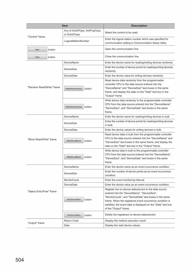
504
Item Description
"Control" frame
Any of ActUtlType, ActProgType,
or DotUtlTypeSelect the control to be used.
LogicalStationNumberEnter the logical station number which was specified for
communication setting in Communication Setup Utility.
button Open the communication line.
button Close the communication line.
"Random Read/Write" frame
DeviceName Enter the device name for reading/writing devices randomly.
DeviceSizeEnter the number of device points for reading/writing devices
randomly.
DeviceData Enter the device value for writing devices randomly.
button
Read device data randomly from the programmable
controller CPU to the data source entered into the
"DeviceName" and "DeviceSize" text boxes in the same
frame, and display the data on the "Data" text box in the
"Output" frame.
button
Write device data randomly to the programmable controller
CPU from the data source entered into the "DeviceName",
"DeviceSize", and "DeviceData" text boxes in the same
frame.
"Block Read/Write" frame
DeviceName Enter the device name for reading/writing devices in bulk.
DeviceSizeEnter the number of device points for reading/writing devices
in bulk.
DeviceData Enter the device values for writing devices in bulk.
button
Read device data in bulk from the programmable controller
CPU to the data source entered into the "DeviceName" and
"DeviceSize" text boxes in the same frame, and display the
data on the "Data" text box in the "Output" frame.
button
Write device data in bulk to the programmable controller
CPU from the data source entered into the "DeviceName",
"DeviceSize", and "DeviceData" text boxes in the same
frame.
"Status Entry/Free" frame
DeviceName Enter the device name as an event occurrence condition.
DeviceSizeEnter the number of device points as an event occurrence
condition.
MonitorCycle Enter the event monitoring interval.
DeviceData Enter the device value as an event occurrence condition.
button
Register the on-device status/event to the data source
entered into the "DeviceName", "DeviceSize",
"MonitorCycle", and "DeviceData" text boxes in the same
frame. When the registered event occurrence condition is
satisfied, the event data is displayed on the "Data" text box
of the "Output" frame.
button Delete the registered on-device status/event.
"Output" frameReturn Code Display the method execution result.
Data Display the read device values.
505
CHAPTER 6 SAMPLE PROGRAMS
6
6.4 Visu
al Basic
® .N
ET
Sam
ple Prog
rams
6.4.3 Type con
version sample program
6.4.3 Type conversion sample program
This sample program is a program to read/write ASCII character string, 32-bit integer, or real number data from/to a
programmable controller CPU devices in the corresponding data format using the ActUtlType control, and display the
error message using the ActSupportMsg control when an error occurs during the process.
This sample program was created on Visual Basic® .NET (Visual Studio® 2005).
(1) How to use the sample program
1. Load the form, enter the logical number, which was specified for the communication setting in
Communication Setup Utility, into the "LogicalStationNumber" text box, and click the
button to open the communication line.
2. For writing ASCII character data to the programmable controller CPU, enter the ASCII character
data into the upper text box in the "ASCII character" frame, and click the button in the
same frame.(The data write function is executed within the range of D0 to D9, regardless of the
number of entered characters. When the number of characters is insufficient, the blanks are filled
with 0 (Hex).)
3. For reading ASCII character data, click the button in the "ASCII character" frame. Data
from the programmable controller CPU is displayed on the lower text box in the same frame. (The
data read function is executed within the range of D0 to D9.)
4. For writing 32-bit integer data to the programmable controller CPU, enter the 32-bit integer data
into the upper text box in the "32bit integer" frame, and click the button in the same
frame. (The data write function is executed within the range of D10 to D11.)
5. For reading 32-bit integer data, click the button in the "32bit integer" frame. Data from the
programmable controller CPU is displayed on the lower text box in the same frame. (The data read
function is executed within the range of D10 to D11.)
6. For writing real number data to the programmable controller CPU, enter the real number data into
the upper text box in the "Real number" frame, and click the button in the same frame.
(The data write function is executed within the range of D12 to D13.)
7. For reading real number data, click the button in the "Real number" frame. Data from the
programmable controller CPU is displayed on the lower text box in the same frame. (The data read
function is executed within the range of D12 to D13.)
8. When an error occurs, perform the troubleshooting corresponds to the error code.
(Page 516, CHAPTER 7 ERROR CODES)
9. Click the button to close the communication line.
(2) Considerations for using the sample program • When using the ActUtlType control, set the communication settings in Communication Setup Utility before
executing the sample program.
• If an error which does not relate to the ActUtlType control occurs (for example, a character string or out-of-
range value is entered for 32-bit integer or real number), the corresponding error message is displayed on
the message box, and the program is terminated.

506
(3) Sample fileThe sample program is installed in the following folder when the default pass is selected.
(4) ScreenThe following explains the settings on the sample program screen.
Folder name File name
[User specified folder] - [Act] - [Samples] - [Vb.NET] - [Sample_TypeConv] Sample_TypeConv.sln
Item Description
LogicalStationNumberEnter the logical station number which was specified for the
communication setting in Communication Setup Utility.
button Open the communication line.
button Close the communication line.
"ASII character" frame
buttonWrite the ASCII character data, which was entered into the upper text
box in the frame, to the programmable controller CPU.
buttonDisplay the ASCII character data, which was read from the
programmable controller CPU, on the lower text box in the frame.
"32bit integer" frame
buttonWrite the 32-bit integer data, which was entered into the upper text box
in the frame, to the programmable controller CPU.
buttonDisplay the 32-bit integer data, which was read from the programmable
controller CPU, on the lower text box in the frame.
"Real number" frame
buttonWrite the real number data, which was entered into the upper text box in
the frame, to the programmable controller CPU.
buttonDisplay the real number data, which was read from the programmable
controller CPU, on the lower text box in the frame.

507
CHAPTER 6 SAMPLE PROGRAMS
6
6.5 Visu
al C+
+®
.NE
T S
ample P
rogram
s6.5.1 R
ead/Write sam
ple program
6.5 Visual C++® .NET Sample Programs
6.5.1 Read/Write sample program
This sample program is a program to read/write device values of a programmable controller CPU and monitor device
status using any of the ActUtlType control, the DotUtlType control, or the ActProgType control.
This sample program was created on Visual C++® .NET (Visual Studio® 2005) and Visual C++® .NET (Visual Studio®
2010).
(1) How to use the sample program
The operation is the same as that for Visual Basic® .NET (Visual Studio® 2005). (Page 502, Section 6.4.2 (1)
How to use the sample program)
(2) Considerations for using the sample program
The considerations are the same as those for Visual Basic® .NET (Visual Studio® 2005). (Page 503, Section
6.4.2 (2) Considerations for using the sample program)
(3) Sample file listThe sample program is installed in the following folder when the default pass is selected.
(a) For Visual C++® .NET (Visual Studio® 2005)
(b) For Visual C++® .NET (Visual Studio® 2010)
(4) Screen
The settings on the screen are the same as those for Visual Basic® .NET (Visual Studio® 2005).
(Page 503, Section 6.4.2 (4) Screen)
Folder name File name
[User specified folder] - [Act] - [Samples] - [Vc.NET] - [Sample2005] Sample2005.sln
[User specified folder] - [Act] - [Samples] - [Vc.NET] -
[Sample_References2005]Sample_References2005.sln
[User specified folder] - [Act] - [Samples] - [Vc.NET] - [SampleDot2005] Sample2005.sln
[User specified folder] - [Act] - [Samples] - [Vc.NET] -
[Sample_ReferencesDot2005]Sample_References2005.sln
Folder name File name
[User specified folder] - [Act] - [Samples] - [Vc.NET] - [Sample2010] Sample2010.sln
[User specified folder] - [Act] - [Samples] - [Vc.NET] -
[Sample_References2010]Sample_References2010.sln
[User specified folder] - [Act] - [Samples] - [Vc.NET] - [SampleDot2010] Sample2010.sln
[User specified folder] - [Act] - [Samples] - [Vc.NET] -
[Sample_ReferencesDot2010]Sample_References2010.sln

508
6.5.2 Troubleshooting function sample program
This sample program is a program to perform the troubleshooting function using the DotSupportMsg control.
(1) How to use the sample program
1. Load the form.
2. Enter the error code into the "ErrorCode" text box to display the error description.
3. Click the button to display the error description and corrective action on the text
box for displaying the error description.
4. Displayed error descriptions and corrective actions are the same as the descriptions on Page
516, CHAPTER 7 ERROR CODES.
5. Click the button to exit the sample program.
(2) Considerations for using the sample programFor error codes to be entered into the "ErrorCode" text box, enter the error code described on Page 516,
Section 7.1 Error Codes Returned by Controls (0x********), or enter it in decimal number.
(3) Sample fileThe sample program is installed in the following folder when the default pass is selected.
Folder name File name
[User specified folder] - [Act] - [Samples] - [Vc.Net] - [Sample_Support] Sample_Support.sln
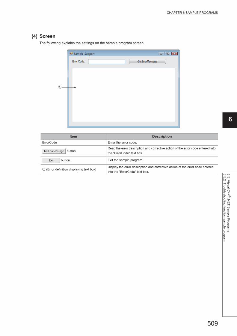
509
CHAPTER 6 SAMPLE PROGRAMS
6
6.5 Visu
al C+
+®
.NE
T S
ample P
rogram
s6.5.2 T
roubleshooting function sam
ple program
(4) ScreenThe following explains the settings on the sample program screen.
Item Description
ErrorCode Enter the error code.
buttonRead the error description and corrective action of the error code entered into
the "ErrorCode" text box.
button Exit the sample program.
(Error definition displaying text box)Display the error description and corrective action of the error code entered
into the "ErrorCode" text box.
1

510
6.6 Visual C#® .NET Sample Programs
6.6.1 Read/Write sample program
This sample program is a program to read/write device values of a programmable controller CPU and monitor device
status using any of the ActUtlType control, the DotUtlType control, or the ActProgType control.
This sample program was created on Visual C#® .NET (Visual Studio® 2005).
(1) How to use the sample program
The operation is the same as that for Visual Basic® .NET (Visual Studio® 2005). (Page 502, Section 6.4.2 (1)
How to use the sample program)
(2) Considerations for using the sample program
The considerations are the same as those for Visual Basic® .NET (Visual Studio® 2005). (Page 503, Section
6.4.2 (2) Considerations for using the sample program)
(3) Sample file listThe sample program is installed in the following folder when the default pass is selected.
(4) Screen
The settings on the screen are the same as those for Visual Basic® .NET (Visual Studio® 2005).
(Page 503, Section 6.4.2 (4) Screen)
Folder name File name
[User specified folder] - [Act] - [Samples] - [Vcs.NET] - [Sample] Sample.sln
[User specified folder] - [Act] - [Samples] - [Vcs.NET] - [Sample_References] Sample_References.sln
[User specified folder] - [Act] - [Samples] - [Vcs.NET] - [SampleDot] Sample.sln
[User specified folder] - [Act] - [Samples] - [Vcs.NET] - [Sample_ReferencesDot] Sample_References.sln

511
CHAPTER 6 SAMPLE PROGRAMS
6
6.7 Visu
al C+
+ ®
.NE
T (M
FC
) Sam
ple Progra
ms
6.7.1 Dispatch in
terface
6.7 Visual C++ ® .NET (MFC) Sample Programs
This section explains the sample programs for Visual C++ ® .NET (MFC) which were created using the dispatch
interface and the custom interface.
6.7.1 Dispatch interface
This sample program is a program to read a model of connected CPU and read/write device values using the
ActUtlType control or the ActProgType control with the dispatch interface.
(1) How to use the sample program
1. Load the form and select the control to be used.
2. Click the button to open the communication line through Ethernet
communication.
3. Click the button to display the model code and the CPU model of the currently-
connected programmable controller CPU on the upper text box and the lower text box of "Output
Data" respectively.
4. Enter the device to be read into the "Device Name" text box, and click the button to
display the device data on the upper text box of "Output Data".
5. Enter the device to be written into the "Device Name" text box, enter the device value to be written
into the "Device Value" text box, and click the button to write the device value.
6. Click the button to close the communication line.
7. If an error occurs during the process, an error code is displayed on the "Return Value" text box.
8. When an error occurs, perform the troubleshooting corresponds to the error code. (Page 516,
CHAPTER 7 ERROR CODES)
(2) Considerations for using the sample program • When using the ActUtlType control, set the logical station number "1" for the Ethernet communication
information in Communication Setup Utility before executing the sample program.
• When changing the control to be used, close the communication line by clicking the
button, change the control, and reopen the line.

512
(3) Sample fileThe sample program is installed in the following folder when the default pass is selected.
(4) ScreenThe following explains the settings on the sample program screen.
Folder name File name
[User specified folder] - [Act] - [Samples] - [Vc] - [SampleENG] sampleENG.sln
Item Description
Control Select the control to be used.
button Open the communication line.
button Read the programmable controller CPU model.
Device Name Enter the device to be read/written.
Device Value Enter the device value to be written.
button Close the communication line.
button Read the data of the device entered into the "Device Name" text box.
button Write the data of the device entered into the "Device Name" text box.
Return Display the function execution result.
OutputUpper Display the CPU model code or the read device value.
Lower Display the CPU model.
513
CHAPTER 6 SAMPLE PROGRAMS
6
6.7 Visu
al C+
+ ®
.NE
T (M
FC
) Sam
ple Progra
ms
6.7.2 Custo
m interface
6.7.2 Custom interface
This sample program is a program to read a model of connected CPU and read/write device values using the
ActUtlType control or ActProgType control with the custom interface.
(1) How to use the sample programThe operation is the same as that for the dispatch interface.(Page 511, Section 6.7.1 (1) How to use the
sample program)
(2) Considerations for using the sample program • When using the ActUtlType control, set the logical station number "2" for the Ethernet communication
information in Communication Setup Utility before executing the sample program.
• When changing the control to be used, close the communication line by clicking the
button, change the control, and reopen the line.
(3) Sample fileThe sample files are installed into the following folders at default installation.
(4) ScreenThe settings on the screen are the same as those for the dispatch interface. (Page 512, Section 6.7.1 (4)
Screen)
Folder name File name
[User specified folder] - [Act] - [Samples] - [Vc] - [CustomSampleENG] CustomSampleENG.sln

514
6.7.3 Troubleshooting function sample program
This sample program is a program to perform the troubleshooting function using the ActSupportMsg control.
(1) How to use the sample program
1. Load the form.
2. Enter the error code into the "ErrorCode" text box to display the error description.
3. Click the button to display the error description and corrective action on the text
box for displaying the error description.
4. Displayed error descriptions and corrective actions are the same as the descriptions on Page
516, CHAPTER 7 ERROR CODES.
5. Click the button to exit the sample program.
(2) Considerations for using the sample programFor error codes to be entered into the "ErrorCode" text box, enter the error code described on Page 516,
Section 7.1 Error Codes Returned by Controls (0x********), or enter it in decimal number.
(3) Sample fileThe sample program is installed in the following folder when the default pass is selected.
Folder name File name
[User specified folder] - [Act] - [Samples] - [Vc] - [Sample_SupportENG] Sample_SupportENG.sln

515
CHAPTER 6 SAMPLE PROGRAMS
6
6.7 Visu
al C+
+ ®
.NE
T (M
FC
) Sam
ple Progra
ms
6.7.3 Troub
leshooting function sample program
(4) ScreenThe following explains the settings on the sample program screen.
Item Description
ErrorCode Enter the error code.
buttonRead the error description and corrective action of the error code entered into
the "ErrorCode" text box.
button Exit the sample program.
(Error definition displaying text box)Display the error description and corrective action of the error code entered
into the "ErrorCode" text box.
1

516
CHAPTER 7 ERROR CODES
This chapter explains the error codes returned by controls and the error codes returned by CPUs, modules, and
network boards.
7.1 Error Codes Returned by Controls
The following table shows the error codes returned by controls.
Error code Error description Corrective action
0x00000000 Normal end –
100Number of ENQ retries is exceeded.
• Take measures against noise.101
102 Number of NACK retries is exceeded.
103 The message is too long.
104 Reception time-out• Check the cable connection.
105 DSR signal was not detected.
106 The line was disconnected.• Check the cable connection.
• Open again.
107 Transmission time-out • Check the cable connection.
108 Sequence number is incorrect. • Take measures against noise.
200 Included DLL was not found. • Reinstall MX Component.
0x01010002 Timeout error
• Check the property timeout value.
• Check the settings in the communication settings utility.
• Check the programmable controller, Unit settings, state
of the cable, etc.
• Close and Open again.
• Exit the program and restart the personal computer.
0x01010005 Message error
• Check the system noise.
• Check the property timeout value.
• Check the settings in the communication settings utility.
• Check the programmable controller, unit settings, status
of the cable, etc.
• Close and Open again.
• Exit the program, restart the personal computer.
0x01010010
Programmable controller No. error
Communication could not be made with the specified
station number.
• Check the station number set on the communication
setup utility.
• Check the station number set to ActStationNumber.
0x01010011Mode error
Command not supported.
• Check if the correct CPU type setting is done.
• Check the programmable controller, Unit settings, status
of the cable, etc.
• Exit the program and restart the personal computer.
• Reinstall MX Component.
0x01010012 Special Unit Specification error • Check the specified address of the special unit.
0x01010013Other data error
Communication cannot be made for some cause.
• Check that the system configuration is not an
unsupported configuration.
• Check that the CPU type setting is correct.
• Exit the program and restart the personal computer.
0x01010018
Remote request error
Remote operation is being performed in the path different
from the communicating path.
• Cancel the remote operation being performed in the
other path.

517
CHAPTER 7 ERROR CODES
7
7.1 Error C
odes Returned by C
ontrols
0x01010020Link error
Link communications could not be made.
• Check that reset operation is not performed for the other
end of communication, the control station (master
station) or the station passed through by routing.
• Check that the network parameter setting is correct.
0x01010021
Special Unit Bus error
There is no response from the special unit under
consideration.
• Repair or exchange the special unit under consideration.
• Exit the program and restart the personal computer.
• Reinstall MX Component.
0x01800001No command error
The method does not support.• The corresponding method does not support.
0x01800002 Memory lock error
• Exit the program and restart the personal computer.
• When using an interface board for personal computer,
increase the minimum working set size of the personal
computer.*1
0x01800003 Memory securing error
• Exit the program and restart the personal computer.
• Exit other programs and secure free memory area.
• When using an interface board for personal computer,
increase the minimum working set size of the personal
computer.*1
0x01800004 DLL load error
• Exit the program and restart the personal computer.
• Exit other programs and secure free memory area.
• Reinstall MX Component.
0x01800005 Resource securing error• Exit the program and restart the personal computer.
• Exit other programs and secure free memory area.
0x01801001
Resource Timeout error
The resource could not be retrieved within the specified
time.
• Execute again after the other object completes the
communication.
• Execute again after increasing the timeout value.
• Exit the program and restart the personal computer.
• Reinstall MX Component.
0x01801002 Multi-line open error• Exit the program and restart the personal computer.
0x01801003 Open not yet executed
0x01801004 Open Type error • Exit the program and restart the personal computer.
• Reinstall MX Component.0x01801005 Specified port error
0x01801006 Specified module error
• Check that the actual system configuration matches to
the settings in the communication settings utility or the
values of the properties.
• Exit the program and restart the personal computer.
• Reinstall MX Component.
0x01801007 Specified CPU error
• Check the CPU type set to ActCpuType.
• Check that the system configuration is not an
unsupported configuration.
• Exit the program and restart the personal computer.
• Reinstall MX Component.
• Check the packet type set to ActPacketType.
0x01801008 Target station access error • Review the target station.
0x01801009Registry open failure
Failed while opening data key of the registry.
• Exit the program and restart the personal computer.
• Reinstall MX Component.
0x0180100APacket Type error
The packet type specified is incorrect.
• Recheck the ActPacketType.
• Exit the program and restart the personal computer.
• Reinstall MX Component.
*1 : For the method for increasing the minimum working set size of the personal computer, refer to the following manual.MELSEC Data Link Library Reference Manual
Error code Error description Corrective action

518
0x0180100BProtocol Type error
The protocol specified is incorrect.• Exit the program and restart the personal computer.
• Reinstall MX Component. 0x0180100C Registry search failure
0x0180100D GetProcAddress failure
0x0180100E DLL non-load error
0x0180100F
Another Object in execution
Method cannot be executed because of exclusive control in
progress.
• Execute again after some time.
0x01802001
Device error
The device character string specified in the method is an
unauthorized device character string.
• Review the device name.
0x01802002
Device number error
The device character string number specified in the
method is an unauthorized device number.
• Review the device number.
0x01802003 Program Type error• Exit the program and restart the personal computer.
• Reinstall MX Component.
0x01802004Sumcheck error
The sumcheck value of the received data is abnormal.
• Check the module side sumcheck setting.
• Check the sumcheck property of the control.
• Check the cable.
• Exit the program and restart the personal computer.
• Reinstall MX Component.
0x01802005
Size error
The number of points specified in the method is
unauthorized.
• Check the number of points specified in the method.
• Review the system, e.g. programmable controller CPU,
module setting and cable status.
• Exit the program and restart the personal computer.
• Reinstall MX Component.
0x01802006
Block number error
The block specifying number in the device character string
specified in the method is unauthorized.
• Review the block specifying number in the device
character string specified in the method.
0x01802007Receive data error
The data received is abnormal.
• Review the system, e.g. programmable controller CPU,
module setting and cable status.
• Check the cable.
• Exit the program and restart the personal computer.
0x01802008 Write Protect error• Exit the program and restart the personal computer.
• Reinstall MX Component. 0x01802009 Reading Parameters error
0x0180200A Writing Parameters error
0x0180200B
Programmable controller type mismatch
The CPU type set to the property and the CPU type set on
the communication settings utility do not match the CPU
type on the other end of communication.
• Set the correct CPU type as the CPU type of the
property.
• Set the correct CPU type on the communication settings
utility.
• Review the system, e.g. programmable controller CPU,
module setting and cable status.
0x0180200CRequest Cancel error
The request was cancelled while being processed.
• Exit the program and restart the personal computer.
• Reinstall MX Component.
0x0180200DDrive Name error
The specified drive name is incorrect.
0x0180200EBeginning Step error
The beginning step specified is incorrect.
0x0180200FParameter Type error
The parameter type is incorrect.
0x01802010File Name error
The file name is incorrect.
Error code Error description Corrective action
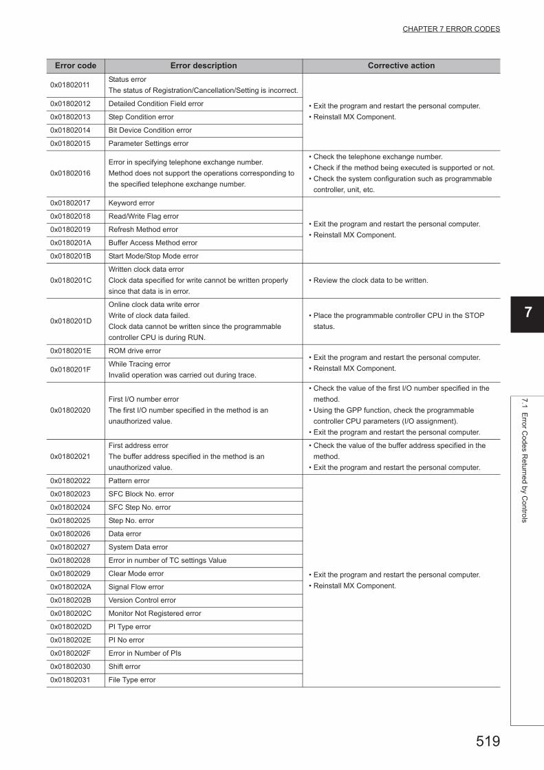
519
CHAPTER 7 ERROR CODES
7
7.1 Error C
odes Returned by C
ontrols
0x01802011Status error
The status of Registration/Cancellation/Setting is incorrect.
• Exit the program and restart the personal computer.
• Reinstall MX Component.
0x01802012 Detailed Condition Field error
0x01802013 Step Condition error
0x01802014 Bit Device Condition error
0x01802015 Parameter Settings error
0x01802016
Error in specifying telephone exchange number.
Method does not support the operations corresponding to
the specified telephone exchange number.
• Check the telephone exchange number.
• Check if the method being executed is supported or not.
• Check the system configuration such as programmable
controller, unit, etc.
0x01802017 Keyword error
• Exit the program and restart the personal computer.
• Reinstall MX Component.
0x01802018 Read/Write Flag error
0x01802019 Refresh Method error
0x0180201A Buffer Access Method error
0x0180201B Start Mode/Stop Mode error
0x0180201C
Written clock data error
Clock data specified for write cannot be written properly
since that data is in error.
• Review the clock data to be written.
0x0180201D
Online clock data write error
Write of clock data failed.
Clock data cannot be written since the programmable
controller CPU is during RUN.
• Place the programmable controller CPU in the STOP
status.
0x0180201E ROM drive error• Exit the program and restart the personal computer.
• Reinstall MX Component.0x0180201FWhile Tracing error
Invalid operation was carried out during trace.
0x01802020
First I/O number error
The first I/O number specified in the method is an
unauthorized value.
• Check the value of the first I/O number specified in the
method.
• Using the GPP function, check the programmable
controller CPU parameters (I/O assignment).
• Exit the program and restart the personal computer.
0x01802021
First address error
The buffer address specified in the method is an
unauthorized value.
• Check the value of the buffer address specified in the
method.
• Exit the program and restart the personal computer.
0x01802022 Pattern error
• Exit the program and restart the personal computer.
• Reinstall MX Component.
0x01802023 SFC Block No. error
0x01802024 SFC Step No. error
0x01802025 Step No. error
0x01802026 Data error
0x01802027 System Data error
0x01802028 Error in number of TC settings Value
0x01802029 Clear Mode error
0x0180202A Signal Flow error
0x0180202B Version Control error
0x0180202C Monitor Not Registered error
0x0180202D PI Type error
0x0180202E PI No error
0x0180202F Error in Number of PIs
0x01802030 Shift error
0x01802031 File Type error
Error code Error description Corrective action

520
0x01802032 Specified Unit error
• Exit the program and restart the personal computer.
• Reinstall MX Component.
0x01802033 Error check flag error
0x01802034 Step RUN operation error
0x01802035 Step RUN data error
0x01802036 During Step RUN error
0x01802037Write error while running program corresponding to
E2PROM
0x01802038
Clock data read/write error
The clock data read/write method was executed for the
programmable controller CPU which does not have the
clock devices.
• Do not execute clock data read/write.
0x01802039 Trace not completed error
• Exit the program and restart the personal computer.
• Reinstall MX Component.
0x0180203A Registration Clear Flag error
0x0180203B Operation error
0x0180203C Error in the number of exchanges
0x0180203D Error in number of loops specified
0x0180203E Retrieve data selection
• Exit the program and restart the personal computer.
• Reinstall MX Component.
0x0180203F Error in number of SFC cycles
0x01802040 Motion programmable controller error
0x01802041 Motion programmable controller Communication error
0x01802042 Fixed execution time setting error
0x01802043 Error in number of functions
0x01802044 System information specification error
0x01802045 Registration Condition Not Formed error
0x01802046 Function No. error
0x01802047 RAM drive error
0x01802048 ROM drive error at the booting side
0x01802049 Transfer mode specification error at the booting side
0x0180204A Insufficient memory error
0x0180204B Back up drive ROM error
0x0180204C Block size error
0x0180204D Detached during RUN state error
0x0180204E Unit Already Registered error
0x0180204F Password Registration Data Full error
0x01802050 Password Not Registered error
0x01802051 Remote Password error
0x01802052 IP Address error
0x01802053 Timeout value out of range error
0x01802054 Command not detected error
0x01802055 Trace execution type error
0x01802056 Version error
0x01802057
Tracking cable error
The tracking cable is faulty.
The programmable controller CPU status is error.
• Reexamine the system such as the programmable
controller CPU, module setting and cable status.
0x0180205CKeyword protection error
Programmable controller is protected by the key word.• Disable the keyword and execute again.
0x0180205DKeyword disable error
The inputted keyword is wrong.• Input a correct keyword.
Error code Error description Corrective action

521
CHAPTER 7 ERROR CODES
7
7.1 Error C
odes Returned by C
ontrols
0x0180205E
Keyword protecting error
Programmable controller did not accept the protecting
command.
• Execute again or re-switch the power of the
programmable controller.
0x0180205FKeyword entry error
An illegal character is included in the inputted keyword.• Input a correct keyword.
0x01802060Keyword deletion error
The inputted keyword is wrong.
0x01802062Received packet CRC check error
An error occurred in CRC check for receive packet data.
• Execute the communication process again.
0x01802063
Received packet CRC check error
An error occurred in CRC check for whole data file of
receive packet.
0x01802064 FX Series programmable controller connection error • Please contact out telephone center.
0x01802070
Online change program error
No target program for online change exists in the
programmable controller CPU.
• Execute the online change after turning the
programmable controller CPU to STOP.
0x01802071
Ether direct communication multiple response receive error
Multiple responses were received during Ether direct
communication. • Check that the personal computer and the
programmable controller CPU are in a one-to-one
connection.0x01802072
Ether direct communication error
Cannot communicate because the programmable
controller CPU is being accessed by another personal
computer during Ether direct communication.
0x01802073
Programmable controller CPU search response error
The number of responses in the programmable controller
CPU search exceeded the maximum number to be
searched.
• Reduce the number of programmable controllers on the
network to 1024 or less.
0x01802074Redundant system other system connection diagnostics
error
• Disconnect the cable and connect it to the currently
disconnected programmable controller CPU.
• Or, change the redundant CPU specification to the self
system.
0x01808001Multiple Open error
Open method was executed while it was open.
• Exit the program and restart the personal computer.
• Execute any method other than Open.
0x01808002
Channel number specifying error
The port number set to the property and the port number
set on the communication settings utility are unauthorized
values.
• Set the correct value to the port number of the property.
• Make communication settings again on the
communication settings utility.
0x01808003Driver not yet started
The network board driver is not started.• Start the driver.
0x01808004 Error in overlap event generation
• Exit the program and restart the personal computer.
• Reinstall MX Component.
0x01808005MUTEX generation error
Creation of MUTEX to exercise exclusive control failed.
0x01808006Error in socket object generation
Socket object could not be created
0x01808007Socket object generation error
Creation of the Socket object failed.
• Check for a running application which uses the same
port number.
• Retry after changing the port number value of the
property.
• Retry after changing the port number value on the
communication settings utility.
• Make Ethernet board and protocol settings on the control
panel of the OS.
• Exit the program and restart the personal computer.
Error code Error description Corrective action
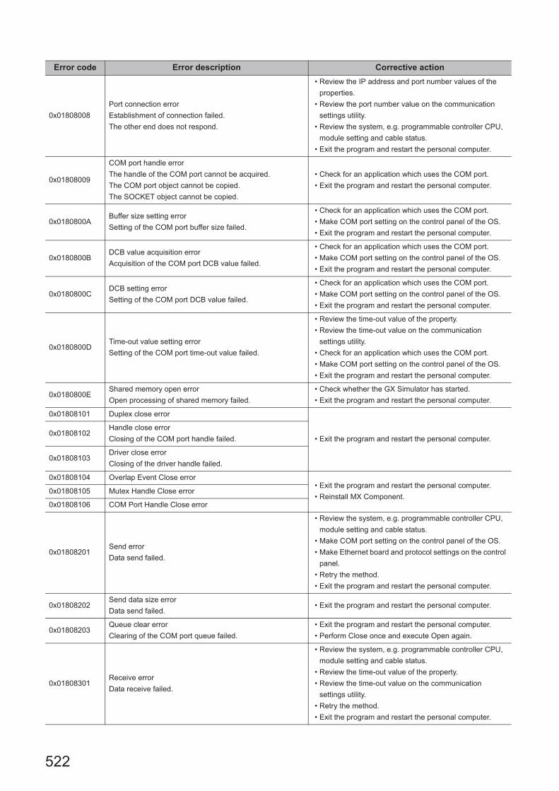
522
0x01808008
Port connection error
Establishment of connection failed.
The other end does not respond.
• Review the IP address and port number values of the
properties.
• Review the port number value on the communication
settings utility.
• Review the system, e.g. programmable controller CPU,
module setting and cable status.
• Exit the program and restart the personal computer.
0x01808009
COM port handle error
The handle of the COM port cannot be acquired.
The COM port object cannot be copied.
The SOCKET object cannot be copied.
• Check for an application which uses the COM port.
• Exit the program and restart the personal computer.
0x0180800ABuffer size setting error
Setting of the COM port buffer size failed.
• Check for an application which uses the COM port.
• Make COM port setting on the control panel of the OS.
• Exit the program and restart the personal computer.
0x0180800BDCB value acquisition error
Acquisition of the COM port DCB value failed.
• Check for an application which uses the COM port.
• Make COM port setting on the control panel of the OS.
• Exit the program and restart the personal computer.
0x0180800CDCB setting error
Setting of the COM port DCB value failed.
• Check for an application which uses the COM port.
• Make COM port setting on the control panel of the OS.
• Exit the program and restart the personal computer.
0x0180800DTime-out value setting error
Setting of the COM port time-out value failed.
• Review the time-out value of the property.
• Review the time-out value on the communication
settings utility.
• Check for an application which uses the COM port.
• Make COM port setting on the control panel of the OS.
• Exit the program and restart the personal computer.
0x0180800EShared memory open error
Open processing of shared memory failed.
• Check whether the GX Simulator has started.
• Exit the program and restart the personal computer.
0x01808101 Duplex close error
• Exit the program and restart the personal computer.0x01808102
Handle close error
Closing of the COM port handle failed.
0x01808103Driver close error
Closing of the driver handle failed.
0x01808104 Overlap Event Close error• Exit the program and restart the personal computer.
• Reinstall MX Component. 0x01808105 Mutex Handle Close error
0x01808106 COM Port Handle Close error
0x01808201Send error
Data send failed.
• Review the system, e.g. programmable controller CPU,
module setting and cable status.
• Make COM port setting on the control panel of the OS.
• Make Ethernet board and protocol settings on the control
panel.
• Retry the method.
• Exit the program and restart the personal computer.
0x01808202Send data size error
Data send failed.• Exit the program and restart the personal computer.
0x01808203Queue clear error
Clearing of the COM port queue failed.
• Exit the program and restart the personal computer.
• Perform Close once and execute Open again.
0x01808301Receive error
Data receive failed.
• Review the system, e.g. programmable controller CPU,
module setting and cable status.
• Review the time-out value of the property.
• Review the time-out value on the communication
settings utility.
• Retry the method.
• Exit the program and restart the personal computer.
Error code Error description Corrective action

523
CHAPTER 7 ERROR CODES
7
7.1 Error C
odes Returned by C
ontrols
0x01808302 Not Sent error • Exit the program and restart the personal computer.
• Reinstall MX Component. 0x01808303 Error in retrieving Overlap Event
0x01808304
Receive buffer size shortage
Receive data was larger than the receive buffer size
prepared for the system. • Exit the program and restart the personal computer.
0x01808401Control error
Changing of the COM port communication control failed.
0x01808402 Signal Line Control error• Exit the program and restart the personal computer.
• Reinstall MX Component.
0x01808403Signal line specifying error
Changing of the COM port communication control failed.• Exit the program and restart the personal computer.
0x01808404 Open not yet executed• Execute Open.
• Exit the program and restart the personal computer.
0x01808405
Communication parameter error
The data bit and stop bit combination of the properties is
unauthorized.
• Review the data bit and stop bit values of the properties.
• Set them again on the communication settings utility.
0x01808406Transmission speed value specifying error
The transmission speed of the property is unauthorized.
• Review the transmission speed value of the property.
• Set it again on the communication settings utility.
0x01808407Data length error
The data bit value of the property is unauthorized.
• Review the data bit value of the property.
• Set it again on the communication settings utility.
0x01808408Parity specifying error
The parity value of the property is unauthorized.
• Review the parity value of the property.
• Set it again on the communication settings utility.
0x01808409Stop bit specifying error
The stop bit value of the property is unauthorized.
• Review the stop bit value of the property.
• Set it again on the communication settings utility.
0x0180840ACommunication control setting error
The control value of the property is unauthorized.
• Review the control value of the property.
• Set it again on the communication settings utility.
0x0180840B
Time-out error
Though the time-out period had elapsed, data could not be
received.
• Review the time-out value of the property.
• Set it again on the communication settings utility.
• Review the system, e.g. programmable controller CPU,
module setting and cable status.
• Retry the method.
• Perform Close once and execute Open again.
• Exit the program and restart the personal computer.
0x0180840C Connect error
• Exit the program and restart the personal computer.
0x0180840D Duplex connect error
0x0180840EAttach failure
Attaching of the socket object failed.
0x0180840FSignal line status acquisition failure
Acquisition of the COM port signal line status failed.
0x01808410
CD signal line OFF
The CD signal on the other end of communication is in the
OFF status.
• Review the system, e.g. programmable controller CPU,
module setting and cable status.
• Exit the program and restart the personal computer.
0x01808411 Password mismatch error • Check the remote password of the property.
0x01808412 TEL Communication error• Exit the program and restart the personal computer.
• Reinstall MX Component.
0x01808501USB driver load error
Loading of the USB driver failed.• Exit the program and restart the personal computer.
• Reinstall MX Component.
• Check USB driver installation.0x01808502USB driver connect error
Connection of the USB driver failed.
Error code Error description Corrective action

524
0x01808503USB driver send error
Data send failed.
• Review the system, e.g. programmable controller CPU,
module setting and cable status.
• Make USB setting on the control panel (device manger)
of the OS.
• Retry the method.
• Exit the program and restart the personal computer.
0x01808504USB driver receive error
Data receive failed.
0x01808505 USB Driver Timeout error
• Recheck the timeout value.
• Exit the program and restart the personal computer.
• Reinstall MX Component.
0x01808506USB driver initialization error
Initialization of the USB driver failed.
• Make USB setting on the control panel (device manger)
of the OS.
• Exit the program and restart the personal computer.
0x01808507Other USB error
Error related to data send/receive occurred.
• Disconnect the cable once, then reconnect.
• Exit the program and restart the personal computer.
• Reinstall MX Component.
0x01809000
GX Works2 uninstallation error
The error occurred by retrieving the installation passing of
GX Simulator2.
• Reinstall GX Works2.
0x01809001GX Simulator2 unstart error
GX Simulator2 did not start.• Start GX Simulator2.
0x01809002 GX Simulator2 start error
• Exit the program and restart the personal computer.
• Reinstall MX Component.
0x01809003 GX Simulator2 start time-out error
0x01809004 GX Simulator2 stop error
0x01809005 GX Simulator2 start error
0x01809007 GX Simulator2 stop error
0x01809008
GX Simulator2 start error
Because it had reached upper bounds of the number of
simulations that was able to be started at the same time, it
was not possible to start.
0x01809009
GX Simulator2 start error
The simulation of only one project that can be started has
started.
0x01809010
GX Simulator2 start information illegal error
The error occurred because it was not able to secure the
memory area to allocate GX Simulator2 start information.
0x01809021
GX Simulator2 start error
Because it had reached upper bounds of the number of
simulations that was able to be started at the same time, it
was not possible to start.
0x01809022
GX Simulator2 start error
The simulation of other CPU was not able to begin
because the simulation of the project of FXCPU had
already been begun.
0x02000001
Points Exceeded error
The number of points registered in the monitoring server is
very high.
• Reduce the no. of points registered by the monitor.
• Exit the program and restart the personal computer.
• Reinstall MX Component.
0x02000002Shared memory creation error
Failed in creating shared memory.• Exit the program and restart the personal computer.
• Reinstall MX Component. 0x02000003 Shared memory access error
0x02000004Memory Secure error
Failed in securing memory for the monitoring server.
• Close the other applications.
• Increase the system memory.
• Exit the program and restart the personal computer.
• Reinstall MX Component.
Error code Error description Corrective action

525
CHAPTER 7 ERROR CODES
7
7.1 Error C
odes Returned by C
ontrols
0x02000005Device Not Registered error
Monitor has not been registered
• Register the monitor in the monitoring server.
• Exit the program and restart the personal computer.
• Reinstall MX Component.
0x02000006Monitoring Server Startup error
Monitoring Server is not started.
• Start the Monitoring Server.
• Exit the program and restart the personal computer.
• Reinstall MX Component.
0x02000010Yet to retrieve Device Value error
Monitoring is not yet completed.
• Try to retrieve the value again after waiting for a fixed
amount of time.
• Exit the program and restart the personal computer.
• Reinstall MX Component.
0x03000001Command not Supported.
Command is not supported.
• Exit the program and restart the personal computer.
• Reinstall MX Component.
0x03000002Memory Lock error
Failed while locking memory.
0x03000003Error Securing Memory
Failed in securing the memory.
0x03000004DLL read error
Failed in reading DLL.
0x03000005Error in securing Resources.
Failed in securing the resources.
0x03010001File Creation error
Failed in creating the file.
• Check if there is enough space on the hard disk.
• Exit the program and restart the personal computer.
• Reinstall MX Component.
0x03010002File Open error
Failed to open the file.
• Exit the program and restart the personal computer.
• Reinstall MX Component.0x03010003
Buffer Size error
The buffer size specified is either incorrect or not enough.
0x03010004SIL Sentence formation error
SIL sentence formation is incorrect.
0x03010005Filename error
The specified filename is too long.
• Specify a shorter filename.
• Exit the program and restart the personal computer.
• Reinstall MX Component.
0x03010006File does not exist error
The specified file does not exist.
• Check the filename.
• Check if the file exists or not.
• Exit the program and restart the personal computer.
• Reinstall MX Component.
0x03010007File Structure error
The data structure in the specified file is incorrect.
• Exit the program and restart the personal computer.
• Reinstall MX Component.
0x03010008File already exists error
The specified file already exists.• Check the filename.
• Exit the program and restart the personal computer.
• Reinstall MX Component.0x03010009File does not exist error
The specified file does not exist.
0x0301000AFile Deletion error
The specified file could not be deleted. • Exit the program and restart the personal computer.
• Reinstall MX Component.0x0301000B
Multiple Open error
The specified project has been opened twice.
0x0301000CFilename error
The specified filename is incorrect.
• Check the filename.
• Exit the program and restart the personal computer.
• Reinstall MX Component.
0x0301000DFile Read error
Failed in reading the file. • Exit the program and restart the personal computer.
• Reinstall MX Component.0x0301000E
File Write error
Failed in writing the file.
Error code Error description Corrective action

526
0x0301000FFile Seek error
File seek failed.
• Exit the program and restart the personal computer.
• Reinstall MX Component.
0x03010010File Close error
Failed while closing the file.
0x03010011Folder Creation error
Failed while creating the folder.
0x03010012File Copy error
Failed while copying the file.
0x03010013Project Path error
The length of the project path is incorrect.
0x03010014Project Type error
The project type is incorrect.
0x03010015File Type error
The file type is incorrect.
0x03010016Sub-File Type error
The sub-file type is incorrect.
0x03010017Insufficient Disk space error
The disk space is insufficient.
0x03020002Multiple Open error
Tried to open DBProduct more than once.
0x03020003Not Opened error
DBProduct is not opened.
0x03020004Extract error
DBProduct is not extracted.
0x03020010Parameter error
The parameters of DBProduct are incorrect.
0x03020011Language error
The language parameter is incorrect.
0x03020012Error in specifying Maker
The maker parameter is incorrect.
0x03020013Error in specifying Unit
The unit parameter is incorrect.
0x03020014SQL Parameter error
SIL, SQL Parameter of DBProduct is incorrect.
0x03020015SIL Sentence formation error
SIL sentence formation is incorrect.
0x03020016Field Key Input error
The field key entered is incorrect.
0x03020050Record Data Construction error.
Failed in reconstructing the record data of DBProduct.
0x03020060Error Retrieving Record Data
Failed while retrieving DBProduct record data.
0x03020061
Last Record error
Cannot retrieve the next record since the current record is
the last record.
0x03FF0000 Initialization error
0x03FF0001 Not Initialized error
0x03FF0002 Multiple Initialization error
0x03FF0003 Workspace Initialization error
0x03FF0004 Database Initialization error
0x03FF0005 Recordset Initialization error
Error code Error description Corrective action

527
CHAPTER 7 ERROR CODES
7
7.1 Error C
odes Returned by C
ontrols
0x03FF0006 Error Closing Database
• Exit the program and restart the personal computer.
• Reinstall MX Component.
0x03FF0007 Error Closing Recordset
0x03FF0008Database Not Opened error
Database is not opened.
0x03FF0009Recordset Not Opened error
Recordset is not opened.
0x03FF000ATable Initialization error
Failed in initializing TtableInformation table.
0x03FF000BTable Initialization error
Failed in initializing TfieldInformation table.
0x03FF000CTable Initialization error
Failed in initializing TrelationInformation table.
0x03FF000DTable Initialization error
Failed in initializing Tlanguage table.
0x03FF000ETable Initialization error
Failed in initializing Tmaker table.
0x03FF000FTable Initialization error
Failed in initializing TOpenDatabase table.
0x03FF0010 Field Value error
0x03FF0011 Field Value error
0x03FF0012Exit error
Failed to exit the database.
0x03FF0100Moving Record error
Failed while moving the record.
0x03FF0101Retrieving Record Count error
Failed to retrieve the record count.
0x03FF0110Retrieving Field Value error
Failed in retrieving the field value.
0x03FF0111Setting Field Value error
Failed in setting the field value.
0x03FFFFFF Other errors
0x04000001
No command error
The specified CPU type cannot be used to perform
processing.
• Check the CPU type set to ActCpuType.
• Check whether the system configuration is supported or
not.
• Exist the program and restart the personal computer.
• Reinstall MX Component.
0x04000002Memory lock error
Failed in locking memory. • Exit the program and restart the personal computer.
• Reinstall MX Component.0x04000003
Securing Memory error
Failed in securing the memory.
0x04000004Internal server DLL load error
Start of the internal server failed.
• Check for the deleted or moved installation file of MX
Component.
• Exit the program and restart the personal computer.
• Reinstall MX Component.
0x04000005Securing Resources error
Failed in securing the resources.
• Exit the program and restart the personal computer.
• Reinstall MX Component.
0x04000006Error Loading Main Object
Failed in reading the file.
0x04000007Error Loading Conversion Table
Failed in reading table data.
0x04000100 Incorrect Intermediate Code Size error
Error code Error description Corrective action

528
0x04010001
Intermediate Code Not Converted error
The converted machine code for one command is more
than 256 bytes.
• Exit the program and restart the personal computer.
• Reinstall MX Component.
0x04010002
Intermediate Code Completion error
Intermediate code area of the code to be converted ended
abruptly.
0x04010003
Insufficient Intermediate Code error
The intermediate code of the code to be converted was
insufficient.
0x04010004Intermediate Code Data error
The intermediate code to be converted is incorrect.
0x04010005Intermediate Code Structure error
The number of steps in the intermediate code is incorrect.
0x04010006
Error in Number of Steps
The number of steps in comment intermediate code is
incorrect.
0x04010007Insufficient Storage Space for Machine Code error
The storage space for machine code is insufficient.
0x04010008
Other errors
(Other errors generated during the conversion of
Intermediate code to machine code.)
0x04011001
Machine Code Not Converted error
The converted intermediate code for one command is more
than 256 bytes.
0x04011002Machine Code Completion error
The machine code area to be converted ended abruptly.
0x04011003
Abnormal Machine Code
Could not convert since the machine code to be converted
was abnormal.
0x04011004Insufficient Storage Space for Intermediate Code error
The storage area for intermediate code is insufficient.
0x04011005
Other errors
Other errors generated while converting machine code to
Intermediate code.
0x04020001
Text Code Not Converted error
The converted intermediate code for one command is more
than 256 bytes.
0x04020002No Input error
The input list code is insufficient.
0x04020003
Command error
The command name of list code to be converted is
incorrect.
0x04020004Device error
The device name of list code to be converted is incorrect.
0x04020005
Device Number error
The device number of the list code to be converted is out of
range.
0x04020006
Conversion error
The list code to be converted conversion could not be
identified.
0x04020007Text Data error
The list code to be converted is incorrect.
Error code Error description Corrective action

529
CHAPTER 7 ERROR CODES
7
7.1 Error C
odes Returned by C
ontrols
0x04020008Error in SFC Operation Output
The output command of SFC operation is incorrect.
• Exit the program and restart the personal computer.
• Reinstall MX Component.
0x04020009SFC Shift Condition error
SFC shift condition command is incorrect.
0x0402000AError in Statements between lines
The statements entered between lines are incorrect.
0x0402000BP.I Statement error
The P.I statement entered is incorrect.
0x0402000CNote error
The Note entered is incorrect.
0x0402000DComment error
The comment entered is incorrect.
0x0402000E
Other errors
(Other errors generated during the conversion of list to
Intermediate code)
0x04021001
Intermediate Code Not Converted error
The converted list code for one command has exceeded
256 bytes.
0x04021002Intermediate Code Area Full error
Intermediate code area to be converted is full.
0x04021003
Command error
The command specified by the intermediate code to be
converted is incorrect.
0x04021004
Device error
The device specified in the intermediate code to be
converted is incorrect.
0x04021005
Intermediate Code error
The structure of intermediate code to be converted is
incorrect.
0x04021006Insufficient List Storage Space error
The space for storing the converted list code is insufficient.
0x04021007
Other errors
(Other errors generated during the conversion of
intermediate code to list)
0x04030001
Not Converted error
The storage space for converted intermediate code is
insufficient.
0x04030002
Bad Circuit Creation error
The character memory circuit is not completed in a
sequence.
0x04030003Specified Circuit Size Exceeded
Specified circuit size is too big.
0x04030004
Incorrect Return Circuit error
There is no consistency before and after the return circuit.
The setting for the return circuit is too high.
0x04030005
Other errors
(Other errors generated while converting from Character
Memory to Intermediate Code)
0x04031001
Not Converted error
The size (vertical/horizontal) of the character memory
specified is incorrect.
Error code Error description Corrective action
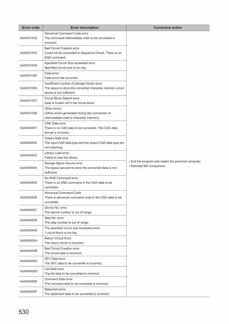
530
0x04031002
Abnormal Command Code error
The command intermediate code to be converted is
incorrect.
• Exit the program and restart the personal computer.
• Reinstall MX Component.
0x04031003
Bad Circuit Creation error
Could not be converted to Sequence Circuit. There is no
END command.
0x04031004Specified Circuit Size exceeded error
Specified circuit size is too big.
0x04031005Fatal error
Fatal error has occurred.
0x04031006
Insufficient number of storage blocks error
The space to store the converted character memory circuit
blocks is not sufficient.
0x04031007Circuit Block Search error
Data is broken off in the circuit block.
0x04031008
Other errors
(Other errors generated during the conversion of
intermediate code to character memory)
0x04040001
CAD Data error
There is no CAD data to be converted. The CAD data
format is incorrect.
0x04040002
Output Data error
The input CAD data type and the output CAD data type are
not matching.
0x04040003Library Load error
Failed to load the library.
0x04040004
Storage Space Secure error
The space secured to store the converted data is not
sufficient.
0x04040005
No END Command error
There is no END command in the CAD data to be
converted.
0x04040006
Abnormal Command Code
There is abnormal command code in the CAD data to be
converted.
0x04040007Device No. error
The device number is out of range.
0x04040008Step No. error
The step number is out of range.
0x04040009The specified circuit size exceeded error.
1 circuit block is too big.
0x0404000AReturn Circuit Error
The return circuit is incorrect.
0x0404000BBad Circuit Creation error
The circuit data is incorrect.
0x0404000CSFC Data error
The SFC data to be converted is incorrect.
0x0404000DList Data error
The list data to be converted is incorrect.
0x0404000EComment Data error
The comment data to be converted is incorrect.
0x0404000FStatement error
The statement data to be converted is incorrect.
Error code Error description Corrective action

531
CHAPTER 7 ERROR CODES
7
7.1 Error C
odes Returned by C
ontrols
0x04040010
Other errors
(Other errors generated during the conversion of CAD
code to Intermediate code.)
• Exit the program and restart the personal computer.
• Reinstall MX Component.
0x04041001
Intermediate Code Data error
There is no intermediate code to be converted. The format
of the intermediate code is incorrect.
0x04041002
CAD Data Type error
The input CAD data type and the output CAD data type are
not matching.
0x04041003Library error
Failed to load the library.
0x04041004Insufficient Input Data error
Data to be converted is insufficient.
0x04041005
Insufficient Storage Space error
There is not enough space to store the CAD data to be
converted.
0x04041006
No END Command error
There is no END command in the CAD data to be
converted.
0x04041007
Abnormal Command Code
There is abnormal command code in the CAD data to be
converted.
0x04041008Device No. error
The device number is out of range.
0x04041009Step No. error
The step number is out of range.
0x0404100AThe specified circuit size exceeded error
1 circuit block is too big.
0x0404100BReturn Circuit error
The return circuit is incorrect.
0x0404100CBad Circuit Creation error
The circuit data is incorrect.
0x0404100DSFC Data error
The SFC data to be converted is incorrect.
0x0404100EList Data error
The list data to be converted is incorrect.
0x0404100FComment Data error
The comment data to be converted is incorrect.
0x04041010Statement error
The statement data to be converted is incorrect.
0x04041011
Other errors
(Other errors generated during the conversion of
Intermediate code to CAD code.)
0x04050001Abnormal Character String Specified error
Device character string specified is incorrect.
0x04050002Device Points error
Device points are out of range.
0x04050003
Other errors
(The errors generated during the conversion of the Device
Character String to Device Intermediate Code)
0x04051001
Device Name error
The classification specified for the device intermediate
code is incorrect.
Error code Error description Corrective action

532
0x04051002
Device Name error
The classification specified for the extended specification
device intermediate code is incorrect.
• Exit the program and restart the personal computer.
• Reinstall MX Component.
0x04051003
Other errors
(The errors generated during the conversion of the Device
Intermediate Code to Device Character String)
0x04052001Abnormal Character String Specified error
Device character string specified is incorrect.
0x04052002Device Points error
Device points are out of range.
0x04052003
Other errors
(The errors generated during the conversion of the Device
Character String to Device Representation Code)
0x04053001
Device Representation error
The classification specified for the device intermediate
code is incorrect.
0x04053002
Device Representation error
The classification specified for the extended specification
device intermediate code is incorrect.
0x04053003Device Representation error
The rectification part specified for the device is incorrect.
0x04053004
Device Representation error
The rectification part specified for the extended device is
incorrect.
0x04053005
Other errors
(The errors generated during the conversion of the Device
Representation Code to Device Character String)
0x04064001Abnormal Device Intermediate Code error
The intermediate code for the device is incorrect.
0x04064002
Other errors
(Other errors generated during the conversion of the
Intermediate code for the Device to Device Name)
0x04065001
Abnormal Device Name error
The classification specified for the intermediate code of the
device is incorrect.
0x04065002
Abnormal Device Name error
The classification for the intermediate code of the extended
specification device is incorrect.
0x04065003
Other errors
(Other errors generated during the conversion of the
device name to Intermediate code)
0x04066001Device Intermediate Code error
The intermediate code for the device is incorrect.
0x04066002
Other errors
(Other errors generated during the conversion of the
device intermediate code to device representation code.)
0x04067001
Device Representation error
The classification specified for the intermediate code of the
device is incorrect.
0x04067002
Device Representation error
The classification for the intermediate code of the extended
specification device is incorrect.
Error code Error description Corrective action

533
CHAPTER 7 ERROR CODES
7
7.1 Error C
odes Returned by C
ontrols
0x04067003Device Representation error
The rectification part specified for the device is incorrect.
• Exit the program and restart the personal computer.
• Reinstall MX Component.
0x04067004
Device Representation error
The rectification part specified for the extended device is
incorrect.
0x04067005
Other errors
(Other errors generated during the conversion of device
representation code to the device intermediate code)
0x04070001
Common Data Conversion error
The input data of the device comment conversion is
incorrect.
0x04070002Insufficient Common Data
The data to be converted is insufficient.
0x04070003
Insufficient Storage Area
The area where the conversion data is stored is
insufficient.
0x04071001
Error in CPU Data Conversion
The input data of the device comment conversion is
incorrect.
0x04071002Insufficient CPU Data error
The data to be converted is insufficient.
0x04071003
Insufficient Storage Area
The area where the conversion data is stored is
insufficient.
0x04072001Open error
Failed in creating conversion object.
0x04072002CPU Type error
The specified CPU type does not exist.
0x04072003Not Converted error
Converted object does not exist.
0x04072004Input Data error
The input data is incorrect.
0x04073001 Program Common Data Conversion error
0x04073002 Program Common Data Conversion error
0x04073101 Program CPU Data Conversion error
0x04074001 Common Data Parameter error
0x04074002Network Parameter Common Data error
The parameter block exists, but the data inside is not set.
0x04074101 Parameter CPU Data error
0x04074102Network Parameter CPU Data error
The parameter block exists, but the data inside is not set.
0x04074103 Offset error
0x04074201Error in Specifying Network Type
The CPU specified does not support the network type.
0x04074202
Parameter Block Number error
The Block corresponding to the parameter block number
specified does not exist.
0x04074203Parameter Block Content error
It is different from the content supported by the specified.
0x04074204Parameter Block Information error
The specified block number does not exist.
Error code Error description Corrective action
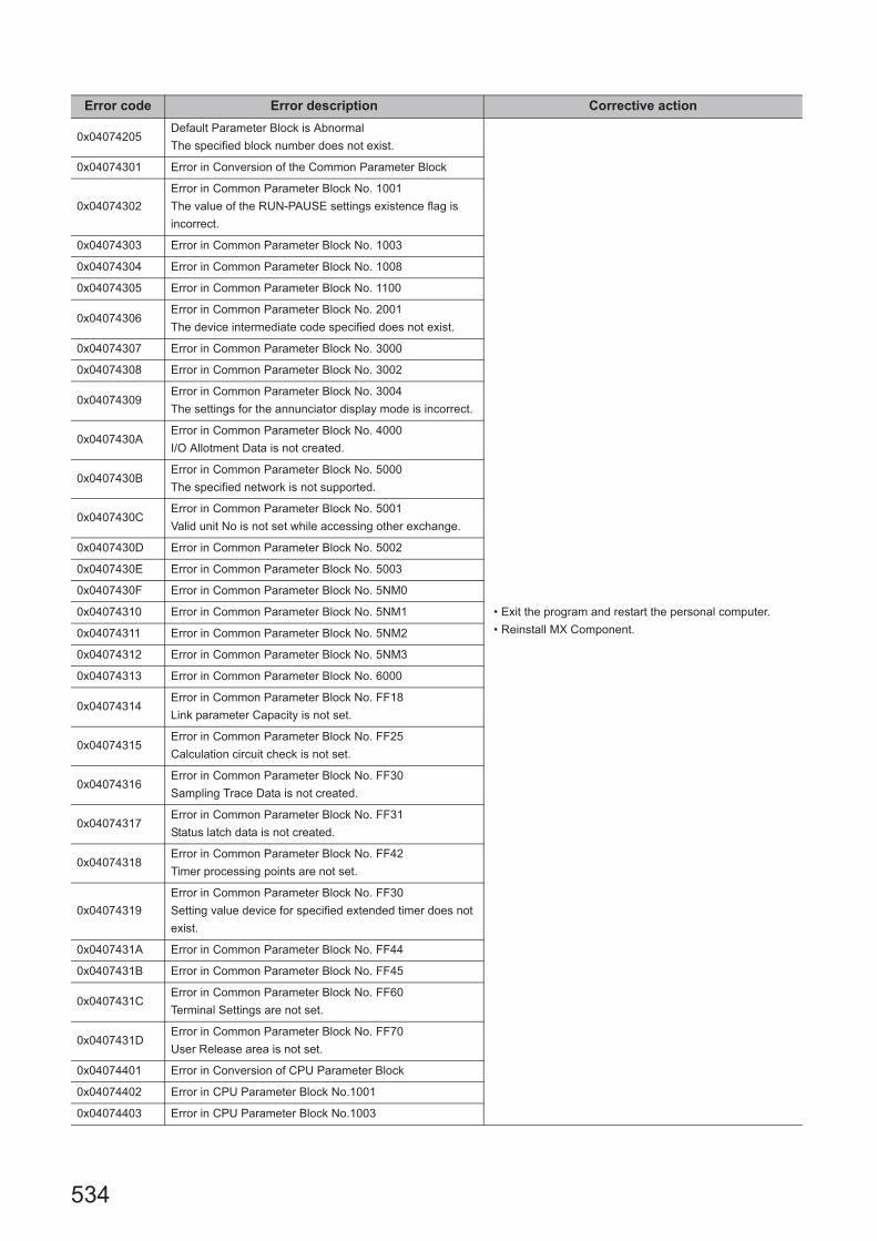
534
0x04074205Default Parameter Block is Abnormal
The specified block number does not exist.
• Exit the program and restart the personal computer.
• Reinstall MX Component.
0x04074301 Error in Conversion of the Common Parameter Block
0x04074302
Error in Common Parameter Block No. 1001
The value of the RUN-PAUSE settings existence flag is
incorrect.
0x04074303 Error in Common Parameter Block No. 1003
0x04074304 Error in Common Parameter Block No. 1008
0x04074305 Error in Common Parameter Block No. 1100
0x04074306Error in Common Parameter Block No. 2001
The device intermediate code specified does not exist.
0x04074307 Error in Common Parameter Block No. 3000
0x04074308 Error in Common Parameter Block No. 3002
0x04074309Error in Common Parameter Block No. 3004
The settings for the annunciator display mode is incorrect.
0x0407430AError in Common Parameter Block No. 4000
I/O Allotment Data is not created.
0x0407430BError in Common Parameter Block No. 5000
The specified network is not supported.
0x0407430CError in Common Parameter Block No. 5001
Valid unit No is not set while accessing other exchange.
0x0407430D Error in Common Parameter Block No. 5002
0x0407430E Error in Common Parameter Block No. 5003
0x0407430F Error in Common Parameter Block No. 5NM0
0x04074310 Error in Common Parameter Block No. 5NM1
0x04074311 Error in Common Parameter Block No. 5NM2
0x04074312 Error in Common Parameter Block No. 5NM3
0x04074313 Error in Common Parameter Block No. 6000
0x04074314Error in Common Parameter Block No. FF18
Link parameter Capacity is not set.
0x04074315Error in Common Parameter Block No. FF25
Calculation circuit check is not set.
0x04074316Error in Common Parameter Block No. FF30
Sampling Trace Data is not created.
0x04074317Error in Common Parameter Block No. FF31
Status latch data is not created.
0x04074318Error in Common Parameter Block No. FF42
Timer processing points are not set.
0x04074319
Error in Common Parameter Block No. FF30
Setting value device for specified extended timer does not
exist.
0x0407431A Error in Common Parameter Block No. FF44
0x0407431B Error in Common Parameter Block No. FF45
0x0407431CError in Common Parameter Block No. FF60
Terminal Settings are not set.
0x0407431DError in Common Parameter Block No. FF70
User Release area is not set.
0x04074401 Error in Conversion of CPU Parameter Block
0x04074402 Error in CPU Parameter Block No.1001
0x04074403 Error in CPU Parameter Block No.1003
Error code Error description Corrective action

535
CHAPTER 7 ERROR CODES
7
7.1 Error C
odes Returned by C
ontrols
0x04074404 Error in CPU Parameter Block No.1008
• Exit the program and restart the personal computer.
• Reinstall MX Component.
0x04074405 Error in CPU Parameter Block No.1100
0x04074406 Error in CPU Parameter Block No.2001
0x04074407 Error in CPU Parameter Block No.3000
0x04074408 Error in CPU Parameter Block No.3002
0x04074409 Error in CPU Parameter Block No.3004
0x0407440A Error in CPU Parameter Block No.4000
0x0407440BError in CPU Parameter Block No.5000
The specified network type is not supported.
0x0407440C Error in CPU Parameter Block No.5001
0x0407440D Error in CPU Parameter Block No.5002
0x0407440E Error in CPU Parameter Block No.5003
0x0407440FError in CPU Parameter Block No. 5NM0
The specified network type is not supported.
0x04074410 Error in CPU Parameter Block No. 5NM1
0x04074411Error in CPU Parameter Block No. 5NM2
The specified network type is not supported.
0x04074412 Error in CPU Parameter Block No. 5NM3
0x04074413 Error in CPU Parameter Block No. 6000
0x04074414 Error in CPU Parameter Block No. FF18
0x04074415 Error in CPU Parameter Block No. FF25
0x04074416 Error in CPU Parameter Block No. FF30
0x04074417 Error in CPU Parameter Block No. FF31
0x04074418 Error in CPU Parameter Block No. FF42
0x04074419 Error in CPU Parameter Block No. FF43
0x0407441A Error in CPU Parameter Block No. FF44
0x0407441B Error in CPU Parameter Block No. FF45
0x0407441C Error in CPU Parameter Block No. FF60
0x0407441D Error in CPU Parameter Block No. FF70
0x04075001
Common Data Conversion error
Failed while converting the device memory settings
portion.
0x04075002Common Data Conversion error
Failed while converting the device memory data portion.
0x04075003Common Data Conversion error
Device memory data portion did not exist.
0x04075101
CPU Data Conversion error
Failed while converting the settings portion of the device
memory.
0x04075102
CPU Data Conversion error
Failed while converting the data portion of the device
memory.
0x04076001
Common Data Conversion error
Failed while converting the settings portion of the device
comments.
0x04076002
Common Data Conversion error
Failed while converting the data portion of the device
comments.
Error code Error description Corrective action
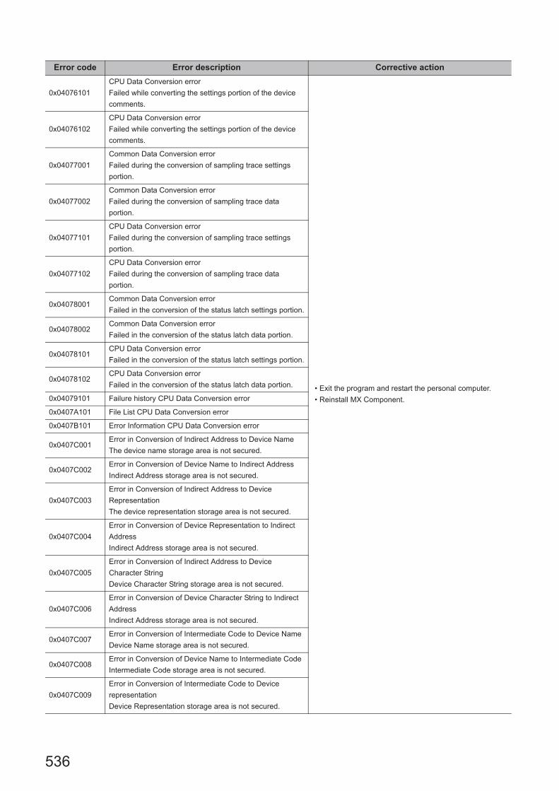
536
0x04076101
CPU Data Conversion error
Failed while converting the settings portion of the device
comments.
• Exit the program and restart the personal computer.
• Reinstall MX Component.
0x04076102
CPU Data Conversion error
Failed while converting the settings portion of the device
comments.
0x04077001
Common Data Conversion error
Failed during the conversion of sampling trace settings
portion.
0x04077002
Common Data Conversion error
Failed during the conversion of sampling trace data
portion.
0x04077101
CPU Data Conversion error
Failed during the conversion of sampling trace settings
portion.
0x04077102
CPU Data Conversion error
Failed during the conversion of sampling trace data
portion.
0x04078001Common Data Conversion error
Failed in the conversion of the status latch settings portion.
0x04078002Common Data Conversion error
Failed in the conversion of the status latch data portion.
0x04078101CPU Data Conversion error
Failed in the conversion of the status latch settings portion.
0x04078102CPU Data Conversion error
Failed in the conversion of the status latch data portion.
0x04079101 Failure history CPU Data Conversion error
0x0407A101 File List CPU Data Conversion error
0x0407B101 Error Information CPU Data Conversion error
0x0407C001Error in Conversion of Indirect Address to Device Name
The device name storage area is not secured.
0x0407C002Error in Conversion of Device Name to Indirect Address
Indirect Address storage area is not secured.
0x0407C003
Error in Conversion of Indirect Address to Device
Representation
The device representation storage area is not secured.
0x0407C004
Error in Conversion of Device Representation to Indirect
Address
Indirect Address storage area is not secured.
0x0407C005
Error in Conversion of Indirect Address to Device
Character String
Device Character String storage area is not secured.
0x0407C006
Error in Conversion of Device Character String to Indirect
Address
Indirect Address storage area is not secured.
0x0407C007Error in Conversion of Intermediate Code to Device Name
Device Name storage area is not secured.
0x0407C008Error in Conversion of Device Name to Intermediate Code
Intermediate Code storage area is not secured.
0x0407C009
Error in Conversion of Intermediate Code to Device
representation
Device Representation storage area is not secured.
Error code Error description Corrective action

537
CHAPTER 7 ERROR CODES
7
7.1 Error C
odes Returned by C
ontrols
0x0407C00A
Error in Conversion of Device Representation to
Intermediate Code
Intermediate Code storage area is not secured.
• Exit the program and restart the personal computer.
• Reinstall MX Component.
0x0407C00B
Error in Conversion of Intermediate Code to Indirect
Address
Indirect Address storage area is not secured.
0x0407C00C
Error in Conversion of Indirect Address to Intermediate
Code
Intermediate Code storage area is not secured.
0x0407C00DCPU Type error
The specified CPU type is not supported.
0x0407C00EDevice Character String error
The specified device is not supported.
0x0407C00FDevice Character String error
The specified device character string, type is incorrect.
0x0407C010
Device error
The specified device is not supported by the specified
CPU.
0x0407C011CPU Type error
The specified CPU is not supported.
0x0407C012 Device out of Range error
0x0407D001Common Data Conversion error
Error in Conversion of SFC trace condition settings portion.
0x0407D002Common Data Conversion error
Error in Conversion of SFC trace condition data portion.
0x0407D101CPU Data Conversion error
Error in Conversion of SFC trace condition settings portion.
0x0407D102CPU Data Conversion error
Error in Conversion of SFC trace condition data portion.
0x04080001
Intermediate Code classification out of range error
The intermediate code classification specified is out of
range.
0x04080002
Extended specification Intermediate Code classification out
of range error
The extended specification intermediate code specified is
out of range.
0x04080003Device Points check absent error
The device does not check the device points.
0x04090001
GPP Project error
The specified CPU type and GPP project type are not
matching.
0x04090002
File Type error
The specified GPP project type and file type are not
matching.
0x04090010
Insufficient GPP Data to be converted
There is no data to be converted. The data size specified is
incorrect.
0x04090011Insufficient Storage Space for Converted Data
The space for storing converted data is insufficient.
0x04090012Error in GPP Data to be converted
The GPP data to be converted is incorrect.
Error code Error description Corrective action

538
0x04090110
Insufficient Data to be converted error
There is no data to be converted. The data size specified is
insufficient.
• Exit the program and restart the personal computer.
• Reinstall MX Component.
0x04090111Insufficient Storage Space for Converted Data error.
The storage space for converted data is insufficient.
0x04090112Error in data to be converted
The data to be converted is incorrect.
0x040A0001Insufficient Intermediate Code Storage Space
The space to store the data after conversion is insufficient.
0x040A0002The space to store addition SFC information is not
sufficient.
0x040A0003 Conversion error
0x040A0004 Non-SFC Program error
0x040A1001 Step Not Used / No Output error
0x040A1002 Step No. out of range error
0x040A1003 Step Not Used / No Output error
0x040A1004 Transition No. out of range
0x040A1005 Maximum Number Exceeded error
0x040A1006 Microcontroller Program space error
0x040A1007 Non-SFC Program error
0x040B0001Insufficient Intermediate Code Storage Space
The space to store the data after conversion is insufficient.
0x040B0002 Conversion error
0x040B1001 Failed in creating Step Start position table
0x040B1002 Error Reading Step Information
0x040B1003 Step No. error
0x040B1004Failed in reading the output of operation/Transition
condition intermediate code error
0x040B1005 Securing Internal Work Area Failed error
0x040B1006Error in setting the maximum value of X direction for
character memory
0x040B1007 Insufficient Internal Work Area error
0x040B1008 Stack Overflow, Abnormal Character Memory
0x040B1009 Insufficient No of Storage Blocks error
0x040B100A Non-SFC Program error
0x04FFFFFF Other errors
0x10000001 No Command error
0x10000002 Start of communication DLL of MX Component failed.
0x10000003 Open failed. (DiskDrive)
0x10000004 Duplex open error • Exit the program and restart the personal computer.
0x10000005 File Access error
• Exit the program and restart the personal computer.
• Reinstall MX Component.
0x10000006 Incorrect Folder Name error
0x10000007 File Access Denied error
0x10000008 Disk Full error
0x10000009 File Delete error
0x1000000A Incorrect File Name error
0x1000000CExecution failed since another application or thread is
making a request.
• Execute again after some time.
• Perform programming according to the multithread rules
of COM and ActiveX.
• Exit the program and restart the personal computer.
Error code Error description Corrective action
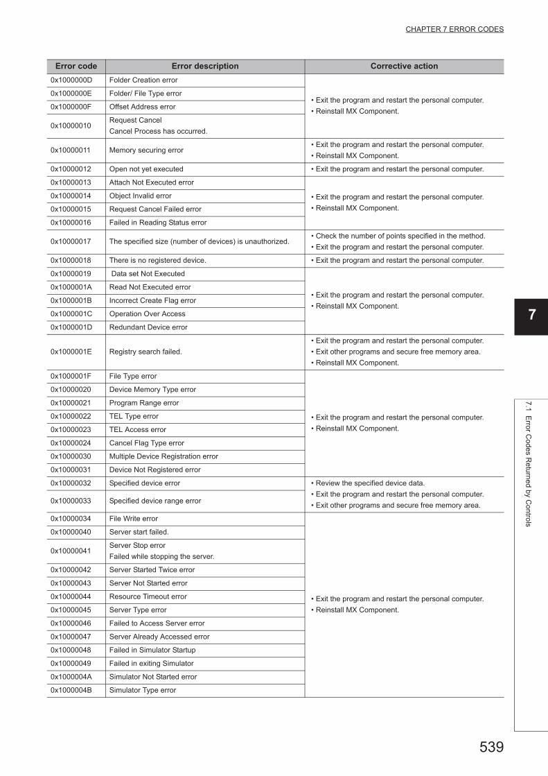
539
CHAPTER 7 ERROR CODES
7
7.1 Error C
odes Returned by C
ontrols
0x1000000D Folder Creation error
• Exit the program and restart the personal computer.
• Reinstall MX Component.
0x1000000E Folder/ File Type error
0x1000000F Offset Address error
0x10000010Request Cancel
Cancel Process has occurred.
0x10000011 Memory securing error• Exit the program and restart the personal computer.
• Reinstall MX Component.
0x10000012 Open not yet executed • Exit the program and restart the personal computer.
0x10000013 Attach Not Executed error
• Exit the program and restart the personal computer.
• Reinstall MX Component.
0x10000014 Object Invalid error
0x10000015 Request Cancel Failed error
0x10000016 Failed in Reading Status error
0x10000017 The specified size (number of devices) is unauthorized.• Check the number of points specified in the method.
• Exit the program and restart the personal computer.
0x10000018 There is no registered device. • Exit the program and restart the personal computer.
0x10000019 Data set Not Executed
• Exit the program and restart the personal computer.
• Reinstall MX Component.
0x1000001A Read Not Executed error
0x1000001B Incorrect Create Flag error
0x1000001C Operation Over Access
0x1000001D Redundant Device error
0x1000001E Registry search failed.
• Exit the program and restart the personal computer.
• Exit other programs and secure free memory area.
• Reinstall MX Component.
0x1000001F File Type error
• Exit the program and restart the personal computer.
• Reinstall MX Component.
0x10000020 Device Memory Type error
0x10000021 Program Range error
0x10000022 TEL Type error
0x10000023 TEL Access error
0x10000024 Cancel Flag Type error
0x10000030 Multiple Device Registration error
0x10000031 Device Not Registered error
0x10000032 Specified device error • Review the specified device data.
• Exit the program and restart the personal computer.
• Exit other programs and secure free memory area.0x10000033 Specified device range error
0x10000034 File Write error
• Exit the program and restart the personal computer.
• Reinstall MX Component.
0x10000040 Server start failed.
0x10000041Server Stop error
Failed while stopping the server.
0x10000042 Server Started Twice error
0x10000043 Server Not Started error
0x10000044 Resource Timeout error
0x10000045 Server Type error
0x10000046 Failed to Access Server error
0x10000047 Server Already Accessed error
0x10000048 Failed in Simulator Startup
0x10000049 Failed in exiting Simulator
0x1000004A Simulator Not Started error
0x1000004B Simulator Type error
Error code Error description Corrective action

540
0x1000004C Simulator Not Supported error• Exit the program and restart the personal computer.
• Reinstall MX Component.0x1000004D Simulator Started Twice error
0x1000004E Shared Memory Not Started error
0x8001000CData out of the allowable setting range is specified.
• Review the value of the property.
• Set it again on the communication settings utility.0x80010016
0x80010101 Timeout error
• Check the property timeout value.
• Check the settings in the communication settings utility.
• Check the Unit settings, state of the cable, etc.
• Close and Open again.
• Exit the program and restart the personal computer.
0x80020001 Type of data is invalid.• Review the value of the property.
• Set it again on the communication settings utility.
0x80020002 Range of the data is incorrect.• Review the value of the property.
• Set it again on the communication settings utility.
0x80030001 The specification of the communication port is incorrect.• Review the communication port value of the property.
• Set it again on the communication settings utility.
0x80030002 The specification of the Transmission speed is incorrect.• Review the transmission speed value of the property.
• Set it again on the communication settings utility.
0x80030003 The specification of the Data bit length is incorrect.• Review the data bit length of the property.
• Set it again on the communication settings utility.
0x80030004 The specification of the parity is incorrect.• Review the parity value of the property.
• Set it again on the communication settings utility.
0x80030005 The specification of the stop bit length is incorrect.• Review the stop bit value of the property.
• Set it again on the communication settings utility.
0x80030006 The specification of the wait time is incorrect.• Review the wait time of the property.
• Set it again on the communication settings utility.
0x80030007 The specification of the CR/LF is incorrect.• Review the CR/LF of the property.
• Set it again on the communication settings utility.
0x80030008 The specification of the timeout is incorrect.• Review the CR/LF of the property.
• Set it again on the communication settings utility.
0x80030009 The specification of the station number is incorrect.• Review the timeout of the property.
• Set it again on the communication settings utility.
0x8003000A USB communication setting is invalid. • Review the value of the property.
• Set it again on the communication settings utility.0x8003000B USB model code is invalid.
0x8003000CDuplication was detected in station number of the USB
communication.
• Review the station number of the property.
• Set it again on the communication settings utility.
0x80200107 Communication error• Try the same method again.
• Exit the program and restart the personal computer.
0x80200203 Memory Secure error• Exit the program and restart the personal computer.
• Exit other programs and secure free memory area.
0x80201001 Specified CPU error • Connect to the supported motion CPU.
0x80201101Already open error
The Open method was executed in the open status.
• When changing the communication target CPU, execute
the Open method after performing Close.
0x80201104 DLL load error
• Exit the program and restart the personal computer.
• Exit other programs and secure free memory area.
• Reinstall MX Component.
0x80201106 Error in Communication object generation• Exit the program and restart the personal computer.
• Reinstall MX Component.
0x80201201Not yet open error
The Open method is not yet executed.
• After executing the Open method, execute the
corresponding method.
0x80201203 Memory Secure error• Exit the program and restart the personal computer.
• Exit other programs and secure free memory area.
Error code Error description Corrective action

541
CHAPTER 7 ERROR CODES
7
7.1 Error C
odes Returned by C
ontrols
0x80204203 Memory Secure error • Exit the program and restart the personal computer.
• Exit other programs and secure free memory area.0x80205203 Memory Secure error
0x80205001 Specified CPU error
• Check the CPU type set to ActCpuType.
• Check that the system configuration is not an
unsupported configuration.
0x80209501 MT Simulator2 start error • Exit the program and restart the personal computer.
0x80209502 MT Simulator2 start error • Exit the program and restart the personal computer.
0x80209503 MT Simulator2 communication error • Exit the program and restart the personal computer.
0x80209504
MT Simulator2 start error
Because it had reached upper bounds of the number of
simulations that was able to be started at the same time, it
was not possible to start.
• Retry after exiting MT Simulator2.
0x80209505 MT Simulator2 stop error • Exit the program and restart the personal computer.
0x80209506 MT Simulator2 stop error • Exit the program and restart the personal computer.
0x8020950FMT Simulator2 stop error
MT Simulator2 is not started.• –
0x80209510MT Simulator2 stop error
MT Simulator2 is not started.• Retry after starting MT Simulator2.
0x80209516MT Simulator2 start error
MT Developer2 is not installed.• Install MT Developer2.
0x80209518MT Simulator2 startup error
The specified number is already used.• Execute after exiting the specified No. of MT Simulator2.
0x80209519 Send data illegal error • Review the argument.
0x8020951CMT Simulator2 start error
MT Simulator2 is ending.• Retry after exiting MT Simulator2.
0x8020951DMT Simulator2 start error
Already executed Open.• Retry after performing Close.
0x8020951E MT Simulator2 non-Open error • –
0x8020951FMT Simulator2 start error
Already executed Open.• Retry after performing Close.
0x80206004 Remote request error• Change the switch on the module to RUN, exit the test
mode, and try again.
0x8020A104 DLL load error
• Exit the program and restart the personal computer.
• Exit other programs and secure free memory area.
• Reinstall MX Component.
0x8020A203 Memory Secure error• Exit the program and restart the personal computer.
• Exit other programs and secure free memory area.
0x80A00101Not yet open error
The Open method is not yet executed.
• After executing the Open method, execute the
corresponding method.
0x80A00104Already open error
The Open method was executed in the open status.
• When changing the communication target CPU, execute
the Open method after performing Close.
0x80A00105 Incorrect data type of the argument • Check the data type being used for the argument.
0x80A00106 Data range of the argument is invalid • Check the value being used for the argument.
0x80A00107 No command error • Not supported by the method.
0x80A00109 Data source cannot be opened. • Check the cable connection.
0x80A0010CThe response format from the robot controller was
incorrect.• Take measures against noise.
0xF0000001No-license error
The license is not given to the personal computer.
• Using the license FD, give the license to the personal
computer.
Error code Error description Corrective action
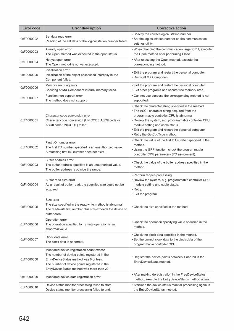
542
0xF0000002Set data read error
Reading of the set data of the logical station number failed.
• Specify the correct logical station number.
• Set the logical station number on the communication
settings utility.
0xF0000003Already open error
The Open method was executed in the open status.
• When changing the communication target CPU, execute
the Open method after performing Close.
0xF0000004Not yet open error
The Open method is not yet executed.
• After executing the Open method, execute the
corresponding method.
0xF0000005
Initialization error
Initialization of the object possessed internally in MX
Component failed.
• Exit the program and restart the personal computer.
• Reinstall MX Component.
0xF0000006Memory securing error
Securing of MX Component internal memory failed.
• Exit the program and restart the personal computer.
• Exit other programs and secure free memory area.
0xF0000007Function non-support error
The method does not support.
• Can not use because the corresponding method is not
supported.
0xF1000001
Character code conversion error
Character code conversion (UNICODE ASCII code or
ASCII code UNICODE) failed.
• Check the character string specified in the method.
• The ASCII character string acquired from the
programmable controller CPU is abnormal.
• Review the system, e.g. programmable controller CPU,
module setting and cable status.
• Exit the program and restart the personal computer.
• Retry the GetCpuType method.
0xF1000002
First I/O number error
The first I/O number specified is an unauthorized value.
A matching first I/O number does not exist.
• Check the value of the first I/O number specified in the
method.
• Using the GPP function, check the programmable
controller CPU parameters (I/O assignment).
0xF1000003
Buffer address error
The buffer address specified is an unauthorized value.
The buffer address is outside the range.
• Check the value of the buffer address specified in the
method.
0xF1000004
Buffer read size error
As a result of buffer read, the specified size could not be
acquired.
• Perform reopen processing.
• Review the system, e.g. programmable controller CPU,
module setting and cable status.
• Retry.
• Exit the program.
0xF1000005
Size error
The size specified in the read/write method is abnormal.
The read/write first number plus size exceeds the device or
buffer area.
• Check the size specified in the method.
0xF1000006
Operation error
The operation specified for remote operation is an
abnormal value.
• Check the operation specifying value specified in the
method.
0xF1000007Clock data error
The clock data is abnormal.
• Check the clock data specified in the method.
• Set the correct clock data to the clock data of the
programmable controller CPU.
0xF1000008
Monitored device registration count excess
The number of device points registered in the
EntryDeviceStatus method was 0 or less.
The number of device points registered in the
EntryDeviceStatus method was more than 20.
• Register the device points between 1 and 20 in the
EntryDeviceStaus method.
0xF1000009 Monitored device data registration error• After making deregistration in the FreeDeviceStatus
method, execute the EntryDeviceStatus method again.
0xF1000010Device status monitor processing failed to start.
Device status monitor processing failed to end.
• Start/end the device status monitor processing again in
the EntryDeviceStatus method.
Error code Error description Corrective action
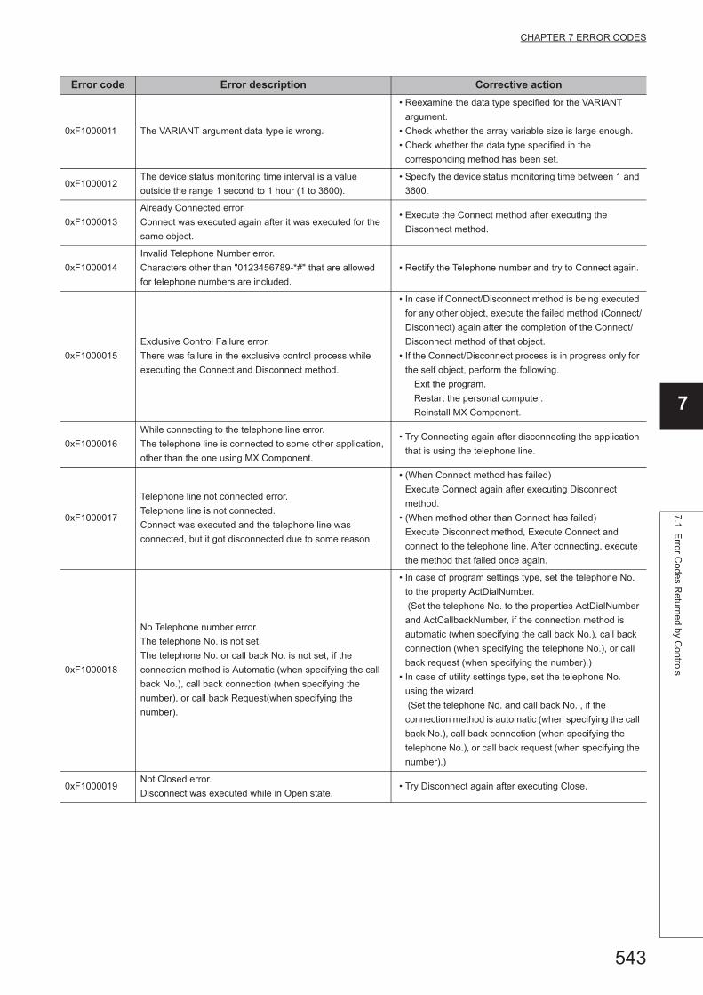
543
CHAPTER 7 ERROR CODES
7
7.1 Error C
odes Returned by C
ontrols
0xF1000011 The VARIANT argument data type is wrong.
• Reexamine the data type specified for the VARIANT
argument.
• Check whether the array variable size is large enough.
• Check whether the data type specified in the
corresponding method has been set.
0xF1000012The device status monitoring time interval is a value
outside the range 1 second to 1 hour (1 to 3600).
• Specify the device status monitoring time between 1 and
3600.
0xF1000013
Already Connected error.
Connect was executed again after it was executed for the
same object.
• Execute the Connect method after executing the
Disconnect method.
0xF1000014
Invalid Telephone Number error.
Characters other than "0123456789-*#" that are allowed
for telephone numbers are included.
• Rectify the Telephone number and try to Connect again.
0xF1000015
Exclusive Control Failure error.
There was failure in the exclusive control process while
executing the Connect and Disconnect method.
• In case if Connect/Disconnect method is being executed
for any other object, execute the failed method (Connect/
Disconnect) again after the completion of the Connect/
Disconnect method of that object.
• If the Connect/Disconnect process is in progress only for
the self object, perform the following.
Exit the program.
Restart the personal computer.
Reinstall MX Component.
0xF1000016
While connecting to the telephone line error.
The telephone line is connected to some other application,
other than the one using MX Component.
• Try Connecting again after disconnecting the application
that is using the telephone line.
0xF1000017
Telephone line not connected error.
Telephone line is not connected.
Connect was executed and the telephone line was
connected, but it got disconnected due to some reason.
• (When Connect method has failed)
Execute Connect again after executing Disconnect
method.
• (When method other than Connect has failed)
Execute Disconnect method, Execute Connect and
connect to the telephone line. After connecting, execute
the method that failed once again.
0xF1000018
No Telephone number error.
The telephone No. is not set.
The telephone No. or call back No. is not set, if the
connection method is Automatic (when specifying the call
back No.), call back connection (when specifying the
number), or call back Request(when specifying the
number).
• In case of program settings type, set the telephone No.
to the property ActDialNumber.
(Set the telephone No. to the properties ActDialNumber
and ActCallbackNumber, if the connection method is
automatic (when specifying the call back No.), call back
connection (when specifying the telephone No.), or call
back request (when specifying the number).)
• In case of utility settings type, set the telephone No.
using the wizard.
(Set the telephone No. and call back No. , if the
connection method is automatic (when specifying the call
back No.), call back connection (when specifying the
telephone No.), or call back request (when specifying the
number).)
0xF1000019Not Closed error.
Disconnect was executed while in Open state.• Try Disconnect again after executing Close.
Error code Error description Corrective action

544
0xF100001A
Target telephone line connection mismatch error.
Connect was tried for a different telephone number using
the port which is already connected to a telephone line.
(When the method of connection is a callback reception, it
is considered that the telephone number is different from
methods of connection in other than the callback
reception.)
• If you want to connect to a different telephone number,
Execute Disconnect with respect to the telephone line
that is already connected and executes Connect after it
gets disconnected.
• In case of connecting the telephone line with callback
reception, use the Connect of the connection method
that is executed at the earliest in the same port as
callback reception.
0xF100001B
Control Type Mismatch error.
An object, whose control type is different from that of the
object already connected to the telephone line, tried to
Connect.
• Execute Disconnect for the object currently connected to
the telephone line and execute Connect once again after
the telephone line gets disconnected.
0xF100001C
Not Disconnected error.
When Disconnect method is executed for the object
connected to the telephone line, it is found that other
objects are in connected state.
• Execute Disconnect for all the Connected objects. Try
Disconnect again for the object that actually performed
the telephone line connection.
0xF100001D
Not Connected error.
Open was executed before Connect.
Or, Disconnect was executed.
• Execute Open again after executing Connect.
• Or execute Disconnect again after executing Connect.
0xF100001E Fatal error.
• Exit the program.
• Restart the personal computer.
• Reinstall MX Component.
0xF100001F
Open time setting error
There is some difference in telephone number and the port
number settings used during Connect and Open.
There is some error in Connect way.
• Check the telephone number and the port number.
• Check the Connect way.
0xF2000002
There is an error response from the target telephone.
Causes can be the following.
• Communication error has occurred.
• Check the value of the properties set in case of program
settings type and check the contents of the detailed
settings that were set using the wizard in case of utility
settings type.
0xF2000003
Invalid data was received.
Causes can be the following.
• Incorrect data packet received due to noise.
• Retry.
• Check the communication device used at the other end.
0xF2000004
There is no response from the modem.
Causes can be the following.
• Abnormality in the modem.
• Telephone number setting mistake.
• Check the status of the modem.
• Check the telephone number.
• If the problem persists even after checking the above
points, change the value of the properties set (Properties
such as ActConnectionCDWaitTime etc. , which set the
timings) in case of program settings type and change the
contents of the detailed settings that were set using the
wizard in case of utility settings type.
0xF2000005 There are chances that the line is not disconnected. • Check the line.
0xF2000006
The PC modem did not receive the AT command.
Causes can be the following.
• Invalid AT command was specified.
• Abnormality in the modem.
• Check the contents of the AT command.
• Check the status of the modem.
0xF2000007Modem did not respond properly to the standard escape
command.
• Check the modem.
• Confirm whether the value of the time-out is too small.
( 5000ms or more is recommended. )
0xF2000009Modem does not respond properly to the line Disconnect
command.• Check the modem.
Error code Error description Corrective action

545
CHAPTER 7 ERROR CODES
7
7.1 Error C
odes Returned by C
ontrols
0xF200000A
Target did not receive the signal.
• The Receive settings of the modem at the other end may
be incorrect.
• The other end may be busy.
• The telephone number may be incorrect.
• Check the Receive settings of the modem at the other
end.
• Check if the other end is busy.
• Check the telephone number.
0xF200000B Timeout reached for the call back receive waiting time.
• Increase the call back receive waiting time
ActCallbackReveptionWaitingTimeOut and execute
connect again.
0xF200000C Password of QJ71C24 units could not be resolved.• Set the password to ActPassword property and execute
the failed method again.
0xF2010001
The callback line disconnect wait time is other than 0 -180
Seconds.
The callback execution delay time is other than 0 -1800
Seconds.
The telephone number is more than 62 characters.
• Check whether the callback line disconnect wait time is
with in 0 - 180 Seconds.
• Check whether the callback execution delay time is with
in 0 - 1800 Seconds.
• Check whether the telephone number is less than or
equal to 62 characters.
• Exit the program and restart the personal computer.
• Reinstall MX Component.
0xF2010002
QJ71C24 did not receive the specified connection method.
Causes can be the following.
• Incorrect Connection method.
• Incorrect telephone number for Call back.
• Check whether the settings of QJ71C24 and the MX
Component are matching.
0xF2010003QJ71C24 does not permit the automatic connection (during
fixed Call back or when the number is specified.) • Check the settings of QJ71C24.
0xF2100005 There are chances that the line is not disconnected.
• If there is no problem with the modem or the telephone
line, change the value of the properties set (Properties
like ActConnectionCDWaitTime etc. , which set the
timings) in case of program settings type and change the
contents of the detailed settings that were set using the
wizard in case of utility settings type.
0xF2100006 Modem did not receive the startup command AT.
• Change the settings of the property ActATCommand. in
case of program settings type and change the command
AT that were set using the wizard in case of utility
settings type.
0xF2100007The PC modem does not respond to the Escape
command.
• If there is no problem with the modem or the telephone
line, change the value of the properties set (Properties
like ActConnectionCDWaitTime etc. , which set the
timings) in case of program settings type and change the
contents of the detailed settings that were set using the
wizard in case of utility settings type.
0xF2100008There was no response from the modem for the data sent
from the PC.
• Change the value of the properties set (Properties such
as ActConnectionCDWaitTime etc. , which set the
timings) in case of program settings type and change the
contents of the detailed settings that were set using the
wizard in case of utility settings type.
0xF21000**
There is no response from the modem.
Causes can be the following.
• Abnormality in the modem.
• Telephone number setting mistake.
• Check the status of the modem.
• Check the telephone number.
• If the problem persists even after checking the above
points, change the value of the properties set (Properties
such as ActConnectionCDWaitTime etc. , which set the
timings) in case of program settings type and change the
contents of the detailed settings that were set using the
wizard in case of utility settings type.
Error code Error description Corrective action

546
0xF202****
There was a communication failure.
Following causes can be considered depending on the
status.
• Communication time over (Break in cable, the specified
port not supported, mistake in specifying the COM port)
• Modem’s power is switched OFF.
• Check whether the cable is broken.
• Check whether the specified port is not supported.
• Check whether correct COM port is set.
• Check if the modem power is switched OFF.
• For detailed troubleshooting, please refer to the details
of the error code got after replacing the first four digits
with "0x0180".
eg In case of "0xF202480B", please refer to the code
"0x0180480B".
0xF3000001
Label error
The label character string specified in the method is an
unauthorized label character string.
• Review the label name.
0xF3000002 Label Service not started • Exit the program and restart the personal computer.
• Reinstall MX Component.0xF3000003 MMS Service not started
0xF3000004The specified LabelSpace is currently being used and
cannot be opened.• Please retry.
0xFF000001MX Component trial version error
Expired MX Component trial version
• Uninstall the trial version and install the commercial
version, or reinstall the trial version.
Error code Error description Corrective action

547
CHAPTER 7 ERROR CODES
7
7.2 Error C
odes Returned by C
PU
s, Modules, an
d Netw
ork Boa
rds
7.2 Error Codes Returned by CPUs, Modules, and Network Boards
This section explains the error codes returned by CPUs, modules, and network boards.
Error codes may not be returned as described in the following (1).Check the considerations described in the (2) first, and refer to the (1).
(1) Error code listIf a CPU, module, or network board detected an error, any of the error codes indicated in the following table is
returned.
The two upper bytes denote the error detection module, and the two lower bytes denote the error code returned
by the error detection module.
For error details, refer to the manual of CPU, module, or network board corresponds to the error code.
*1 : Refer to "Point"*2 : The error codes are also described in the following section.
Page 516, Section 7.1 Error Codes Returned by Controls
(2) Considerations for confirming error codesThe following are the considerations for confirming the error codes returned by CPU, module, and network board.
(a) Property setting error
If the used system configuration does not match the preset property values, the two upper bytes do not indicate
the correct error detection module.
For example, when the property values of FXCPU are set to ActCpuType for QCPU (Q mode), the two upper
bytes may indicate that the error detection module is FXCPU.
In such a case, perform the communication again after checking the system configuration and all preset
property values.
When the ActEasyIF or ActMLEasyIF control is used, check the settings of Communication Setup Utility.
(b) When accessing another station
When accessing another station, the error code of the used relayed module (CC-Link IE Controller Network,
MELSECNET/H, CC-Link, Serial communication, Ethernet module) may be entered to the two lower bytes.
In such a case, the two upper bytes that indicate the error detection module may not always match the faulty
module. Check the system configuration, and check the manuals of the used CPU, relayed network module,
and network board.
Error code Error detection module
0x01010000 to 0x0101FFFF*1,*2 Motion controller CPU
0x01070000 to 0x0107FFFF*1 CC-Link IE Controller Network board, MELSECNET/H board, CC-Link board
0x01090000 to 0x0109FFFF*1 FXCPU
0x010A0000 to 0x010AFFFF*1 QCPU (Q mode), QSCPU, RCPU, FX5CPU
0x010B0000 to 0x010BFFFF*1 Q series-compatible C24
0x010C0000 to 0x010CFFFF*1 Q series-compatible E71
0x010D0000 to 0x010DFFFF*1 PC CPU module
0x010F0000 to 0x010FFFFF*1 GOT

548
(3) Label specification errorThe following error code will be returned if an error related to labels in the CPU occurred such as; system label
Ver.2 does not exist, the information of system label Ver.2 is modified while reading/writing devices that are
corresponding to the system label Ver.2.
Error code Error description Corrective action
0x01802001 Label information errer
• When a system label is specified as a label, review the global label name
assigned to the system label name in Label Utility.
• Check if the global labels exist in the CPU.
0x010A4000 to
0x010A4FFF
For the errors and their corrective actions, refer to the following manual.
MELSEC iQ-R CPU Module User's Manual (Application)

549
CHAPTER 7 ERROR CODES
7
7.3 HR
ES
ULT
Type
Error C
odes
7.3 HRESULT Type Error Codes
Normally, the ActiveX control and the ACT control return HRESULT type returned values.
When the custom interface is used, the returned value is equivalent to the returned value of method API.
When the dispatch interface is used, HRESULT type returned values can be acquired by performing the exception
processing.
The following table shows HRESULT type returned values of ACT controls.
If the exception processing to acquire the HRESULT type returned value is not performed, the dispatch interface displays the error dialog box on the operating system level when E_POINTER (E_XXXXX defined returned value) or the like is returned from the ACT control.
7.4 Error Codes Displayed on Event Viewer
This section explains the error codes displayed on Windows® Event Viewer by MX Component.
MX Component uses MMS (system label database) Service and Label Service to manage label information.
When an error occurs in Label Service, an error description is displayed on the system log in Event Viewer.
For errors regarding Label Service of MX Component, "MXLabelService" is displayed on the source field in Event
Viewer.
The following table shows the errors and their corrective actions.
Returned value Termination status Description
S_OK Normal termination The function processing is normally terminated.
S_FALSE Normal terminationThe function processing (as ActiveX control) is normally terminated, but the
operation (access to programmable controller) failed.
E_POINTER Abnormal termination The pointer passed to the function is abnormal.
E_OUTOFMEMORY Abnormal termination Memory reservation or object creation failed.
E_FAIL Abnormal termination An indefinite error occurred.
Event ID Error message Corrective action
3 MMS Service not started.
• Wait for the completion of MMS (system label database) Service
startup.
If MMS Service startup does not complete, exit the program and
restart the personal computer.
• Reinstall MX Component.
5
MXLabelService error (%1,%2)
Please perform one of the following operations.
- Restart the personal computer.
- Reinstall the application and try again.
• Exit the program and restart the personal computer.
• Reinstall MX Component.

550
APPENDIX
Appendix 1 Connection System of Callback Function
This section explains the connection system of the callback function for modem communication using Q series-
compatible C24.
The callback function enables access from MX Component to a programmable controller CPU by the line reconnection
(callback) performed from Q series-compatible C24 after the line connection from MX Component.
• For (1) to (3), the telephone use fees are charged on the personal computer side.
• For (4) to (8), the telephone use fees are charged on Q series-compatible C24 side.
For details of the callback function, refer to the following manual.
Q Corresponding Serial Communication Module User's Manual (Application)
(1) Auto line connectSelect this when the callback function is not set to Q series-compatible C24.
(2) Auto line connect (Callback fixation)Connect the line without using the callback function when the callback function is set to Q series-compatible C24.
Only personal computers whose telephone number is registered in the buffer memory (2101H) of Q series-
compatible C24 can be connected.
(3) Auto line connect (Callback number specification)Connect the line without using the callback function when the callback function is set to Q series-compatible C24.
Only personal computers whose telephone number is specified by MX Component can be connected.
(4) Callback connect (Fixation)Callback only personal computers whose telephone number is registered in the buffer memory (2101H) of Q
series-compatible C24.
(5) Callback connect (Number specification)Callback only personal computers whose telephone number is specified by MX Component.
(6) Callback request (Fixation)Send a callback request from the selected personal computer to callback personal computers whose telephone
number is registered in the buffer memory (2101H) of Q series-compatible C24. (The callback is not performed on
the personal computer which is connected first.)
(7) Callback request (Number specification)Send a callback request from the selected personal computer to callback personal computers whose telephone
number is specified by MX Component. (The callback is not performed on the personal computer which is
connected first.)
(8) Callback reception waitingWhen connecting a line with callback request (fixation, number specification), "Callback reception waiting" is
selected on the callback target personal computer to connect the line.

551
APPENDIX
A
Appendix 2 P
rogramm
ing E
xamples for M
onitoring Word D
evice Status
Appendix 2 Programming Examples for Monitoring Word Device Status
This section explains the programming examples to monitor word devices for negative values using the
EntryDeviceStatus function.
(1) When using Visual Basic® .NET
The following is a programming example to monitor D0 for -10, D1 for 0, and D2 for 10 using Visual Basic® 6.0.
<When ldata = -1>
Dim szDevice As String 'Checked device list
Dim lInputData(2) As Long 'Set value
Dim lEntryData(2) As Long 'Value set to argument of EntryDeviceStatus
Dim lReturnCode As Long 'Returned value to EntryDeviceStatus
Dim lCount As Long 'Loop counter
'Sets D0, D1 and D2 to the checked device list.
szDevice = "D0" + vbLf + "D1" + vbLf + "D2"
'Sets the checked device value "-10" for D0.
lInputData(0) = -10
'Sets the checked device value "0" for D1.
lInputData(1) = 0
'Sets the checked device value "10" for D2.
lInputData(2) = 10
'If the set value is negative, stores "0"s into the upper 2 bytes
'for conversion into the value to be set to EntryDeviceStatus.
'Loops through the number of device points.
For lCount = 0 To 2
'If the set value is negative
If lInputData(lCount) < 0 Then
'Masks with 65535 (0000FFFF[hex]) to store "0"s into upper 2 bytes.
lEntryData(lCount) = lInputData(lCount) And 65535
Else
'If the set value is positive, assigns the value as-is to lEntryData.
lEntryData(lCount) = lInputData(lCount)
End If
Next
'Executes EntryDeviceStatus.
lReturnCode = AxActUtlType1.EntryDeviceStatus(szDevice, 3, 5, lEntryData(0))
Private Sub AxActUtlType1_OnDeviceStatus(ByVal szDevice As String, ByVal lData As Long, ByVal lReturnCode As Long)
Dim lCheckData As Long 'Value set to EntryDeviceStatus (value before 0s are stored into the upper 2 bytes)
'If the device value whose condition was established is a WORD type negative value (greater than 32767 (7FFF[Hex])
If lData > 32767 Then
'Since "0"s are stored in the upper 2 bytes, the device value is ORed with FFFF0000[Hex] to convert it into a LONG
'type negative value.
lCheckData = lData Or &HFFFF0000
Else
'If the device value whose condition was established is positive, assigns the value as-is to lCheckData.
lCheckData = lData
End If
End Sub

552
(2) When using Visual C++® .NET
The following is a programming example to monitor D0 for -10, D1 for 0, and D2 for 10 using Visual C++® .NET.
<When ldata = -1>
CString szDevice; //Checked device list
LONG lInputData[3]; //Set value
LONG lEntryData[3]; //Value set to argument of EntryDeviceStatus
LONG lReturnCode; //Returned value to EntryDeviceStatus
LONG lCount; //Loop counter
//Sets D0, D1 and D2 to the checked device list.
szDevice = "D0\nD1\nD2";
// Sets the checked device value "-10" for D0.
lInputData[0] = -10;
// Sets the checked device value "0" for D1.
lInputData[1] = 0;
// Sets the checked device value "10" for D2.
lInputData[2] = 10;
//If the set value is negative, stores "0"s into the upper 2 bytes
//for conversion into the value to be set to EntryDeviceStatus.
//Loops through the number of device points.
for(lCount = 0;lCount<=2; lCount++) {
//If the set value is negative
if (lInputData[lCount] < 0 ){
//Masks with 65535 (0000FFFF[hex]) to store "0"s into upper 2 bytes.
lEntryData[lCount] = lInputData[lCount] & 0x0000FFFF;
}else{
//If the set value is positive, assigns the value as-is to lEntryData.
lEntryData[lCount] = lInputData[lCount];
}
}
//Executes EntryDeviceStatus.
lReturnCode = m_Actutltype.EntryDeviceStatus(szDevice,3,5,lEntryData);
void CSampleDlg::OnDeviceStatusActutltype1(LPCTSTR szDevice, long lData, long lReturnCode)
{
LONG lCheckData; //Value set to EntryDeviceStatus
//If the device value whose condition was established is a WORD type negative value
//greater than 32767 (7FFF[Hex])
if(lData > 0x7FFF){
//Since "0"s are stored in the upper 2 bytes, the device value is ORed
//with FFFF0000[Hex] to convert it into a LONG type negative value.
lCheckData = lData | 0xFFFF0000;
}else{
//If the device value whose condition was established is positive,
//assigns the value as-is to lCheckData.
lCheckData = lData;
}
}

553
APPENDIX
A
Appendix 2 P
rogramm
ing E
xamples for M
onitoring Word D
evice Status
(3) When using Visual C#® .NET
The following is a programming example to monitor D0 for -10, D1 for 0, and D2 for 10 using Visual C#® .NET.
String szDevice; //Checked device list
int[] inputData = new int[3]; //Set value
int[] iEntryData = new int[3]; //Value set to argument of EntryDeviceStatus
int iReturnCode; //Returned value to EntryDeviceStatus
int iCount; //Loop counter
//Sets D0, D1 and D2 to the checked device list.
szDevice = "D0\nD1\nD2";
// Sets the checked device value "-10" for D0.
iInputData[0] = -10;
// Sets the checked device value "0" for D1.
iInputData[1] = 0;
// Sets the checked device value "10" for D2.
iInputData[2] = 10;
//If the set value is negative, stores "0"s into the upper 2 bytes
//for conversion into the value to be set to EntryDeviceStatus.
//Loops through the number of device points.
for(lCount = 0;lCount<=2; lCount++) {
//If the set value is negative
if (lInputData[lCount] < 0 ){
//Masks with 65535 (0000FFFF[hex]) to store "0"s into upper 2 bytes.
lEntryData[lCount] = lInputData[lCount] & 0x0000FFFF;
}else{
//If the set value is positive, assigns the value as-is to lEntryData.
lEntryData[lCount] = lInputData[lCount];
}
}
axActUtlType1.ActLogicalStationNumber = 0;
iReturnCode = axActUtlType1.Open();
//Executes EntryDeviceStatus.
iReturnCode =axActUtlType1.EntryDeviceStatus(szDevice, 3, 5, ref iEntryData[0]);

554
Appendix 3 Time-Out Periods
In MX Component, a time-out may occur at the period different from the value set to the ActTimeOut property in the
ACT control.
This section explains the time-out periods in various status.
Appendix 3.1 Communication retries at time-out error occurrence
If a time-out error occurs during communication, the time-out processing may be repeated for a maximum of three
times in the ACT control.
At that time, the process takes a maximum of three times longer period than the set time-out value which is a period
until the time-out occurrence.
The following shows communication paths for retries at a time-out error occurrence.
(1) Serial communication
(a) Configuration
Personal computer
Connected
station CPU
Connected
module
Relayed
module
Relayed network
Relayed
station CPU
Relayed
module
1 2
3
4
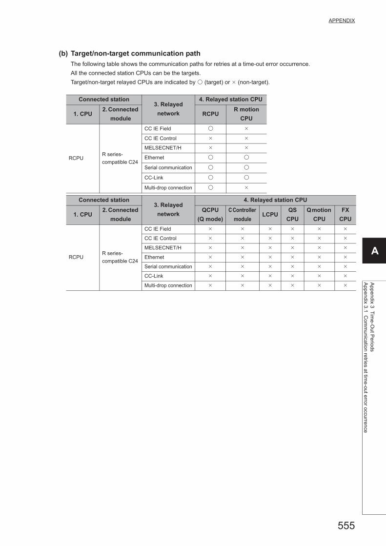
555
APPENDIX
A
Appendix 3 T
ime-O
ut Periods
Appendix 3.1 C
omm
unication retrie
s at time-out error occurrence
(b) Target/non-target communication path
The following table shows the communication paths for retries at a time-out error occurrence.
All the connected station CPUs can be the targets.
Target/non-target relayed CPUs are indicated by (target) or (non-target).
Connected station3. Relayed
network
4. Relayed station CPU
1. CPU2. Connected
moduleRCPU
R motion
CPU
RCPUR series-
compatible C24
CC IE Field
CC IE Control
MELSECNET/H
Ethernet
Serial communication
CC-Link
Multi-drop connection
Connected station3. Relayed
network
4. Relayed station CPU
1. CPU2. Connected
module
QCPU
(Q mode)
C Controller
moduleLCPU
QS
CPU
Q motion
CPU
FX
CPU
RCPUR series-
compatible C24
CC IE Field
CC IE Control
MELSECNET/H
Ethernet
Serial communication
CC-Link
Multi-drop connection

556
Connected station3. Relayed
network
4. Relayed station CPU
1. CPU2. Connected
moduleRCPU
R motion
CPU
QCPU
(Q mode)
Q series-
compatible C24
CC IE Field
CC IE Control
MELSECNET/H
Ethernet
Serial communication
CC-Link
Multi-drop connection
Connected station3. Relayed
network
4. Relayed station CPU
1. CPU2. Connected
module
QCPU
(Q mode)
C Controller
moduleLCPU
QS
CPU
Q motion
CPU
FX
CPU
QCPU
(Q mode)
Q series-
compatible C24
CC IE Field
CC IE Control
MELSECNET/H
Ethernet
Serial communication
CC-Link
Multi-drop connection
Connected station3. Relayed
network
4. Relayed station CPU
1. CPU2. Connected
moduleRCPU
R motion
CPU
LCPUL series-
compatible C24
CC IE Field
CC IE Control
MELSECNET/H
Ethernet
Serial communication
CC-Link
Multi-drop connection
Connected station3. Relayed
network
4. Relayed station CPU
1. CPU2. Connected
module
QCPU
(Q mode)
C Controller
moduleLCPU
QS
CPU
Q motion
CPU
FX
CPU
LCPUL series-
compatible C24
CC IE Field
CC IE Control
MELSECNET/H
Ethernet
Serial communication
CC-Link
Multi-drop connection

557
APPENDIX
A
Appendix 3 T
ime-O
ut Periods
Appendix 3.1 C
omm
unication retrie
s at time-out error occurrence
Connected station3. Relayed
network
4. Relayed station CPU
1. CPU2. Connected
moduleRCPU
R motion
CPU
FXCPUFX extended
port
CC IE Field
CC IE Control
MELSECNET/H
Ethernet
Serial communication
CC-Link
Multi-drop connection
Connected station
3. Relayed
network
4. Relayed station CPU
1. CPU2. Connected
module
QCPU
(Q mode)
C
Controller
module
LCPUQS
CPU
Q motion
CPU
FX
CPU
FXCPUFX extended
port
CC IE Field
CC IE Control
MELSECNET/H
Ethernet
Serial communication
CC-Link
Multi-drop connection

558
(2) CPU COM communication
(a) Configuration
(b) Target/non-target communication path
The following table shows the communication paths for retries at a time-out error occurrence.
All the connected station CPUs can be the targets.
Target/non-target relayed CPUs are indicated by (target) or (non-target).
1. Connected
module2. Relayed network
3. Relayed station CPU
RCPUR motion
CPU
FX5CPU
CC IE Field
CC IE Control
MELSECNET/H
Ethernet
Serial communication
CC-Link
1. Connected
module2. Relayed network
3. Relayed station CPU
QCPU
(Q mode)
C Controller
moduleLCPU
QS
CPU
Q motion
CPU
FX
CPU
FX5CPU
CC IE Field
CC IE Control
MELSECNET/H
Ethernet
Serial communication
CC-Link
Personal computer
Connected
station CPU
Relayed
module
Relayed network
Relayed
station CPU
Relayed
module
1
2
3

559
APPENDIX
A
Appendix 3 T
ime-O
ut Periods
Appendix 3.1 C
omm
unication retrie
s at time-out error occurrence
1. Connected
module2. Relayed network
3. Relayed station CPU
RCPUR motion
CPU
QCPU (Q mode)
CC IE Field
CC IE Control
MELSECNET/H
Ethernet
Serial communication
CC-Link
1. Connected
module2. Relayed network
3. Relayed station CPU
QCPU
(Q mode)
C Controller
moduleLCPU
QS
CPU
Q motion
CPU
FX
CPU
QCPU (Q mode)
CC IE Field
CC IE Control
MELSECNET/H
Ethernet
Serial communication
CC-Link
1. Connected
module2. Relayed network
3. Relayed station CPU
RCPUR motion
CPU
LCPU
CC IE Field
CC IE Control
MELSECNET/H
Ethernet
Serial communication
CC-Link
1. Connected
module2. Relayed network
3. Relayed station CPU
QCPU
(Q mode)
C Controller
moduleLCPU
QS
CPU
Q motion
CPU
FX
CPU
LCPU
CC IE Field
CC IE Control
MELSECNET/H
Ethernet
Serial communication
CC-Link

560
*1 : Only FX3G(C)CPU and FX3U(C)CPU can be accessed.
1. Connected
module2. Relayed network
3. Relayed station CPU
RCPUR motion
CPU
Q motion CPU
CC IE Field
CC IE Control
MELSECNET/H
Ethernet
Serial communication
CC-Link
1. Connected
module2. Relayed network
3. Relayed station CPU
QCPU
(Q mode)
C
Controller
module
LCPUQS
CPU
Q motion
CPU
FX
CPU
Q motion CPU
CC IE Field
CC IE Control
MELSECNET/H
Ethernet
Serial communication
CC-Link
1. Connected
module2. Relayed network
3. Relayed station CPU
RCPUR motion
CPU
FXCPU
CC IE Field
CC IE Control
MELSECNET/H
Ethernet
Serial communication
CC-Link
1. Connected
module2. Relayed network
3. Relayed station CPU
QCPU
(Q mode)
C
Controller
module
LCPUQS
CPU
Q motion
CPU
FX
CPU
FXCPU
CC IE Field
CC IE Control
MELSECNET/H
Ethernet
Serial communication
CC-Link *1
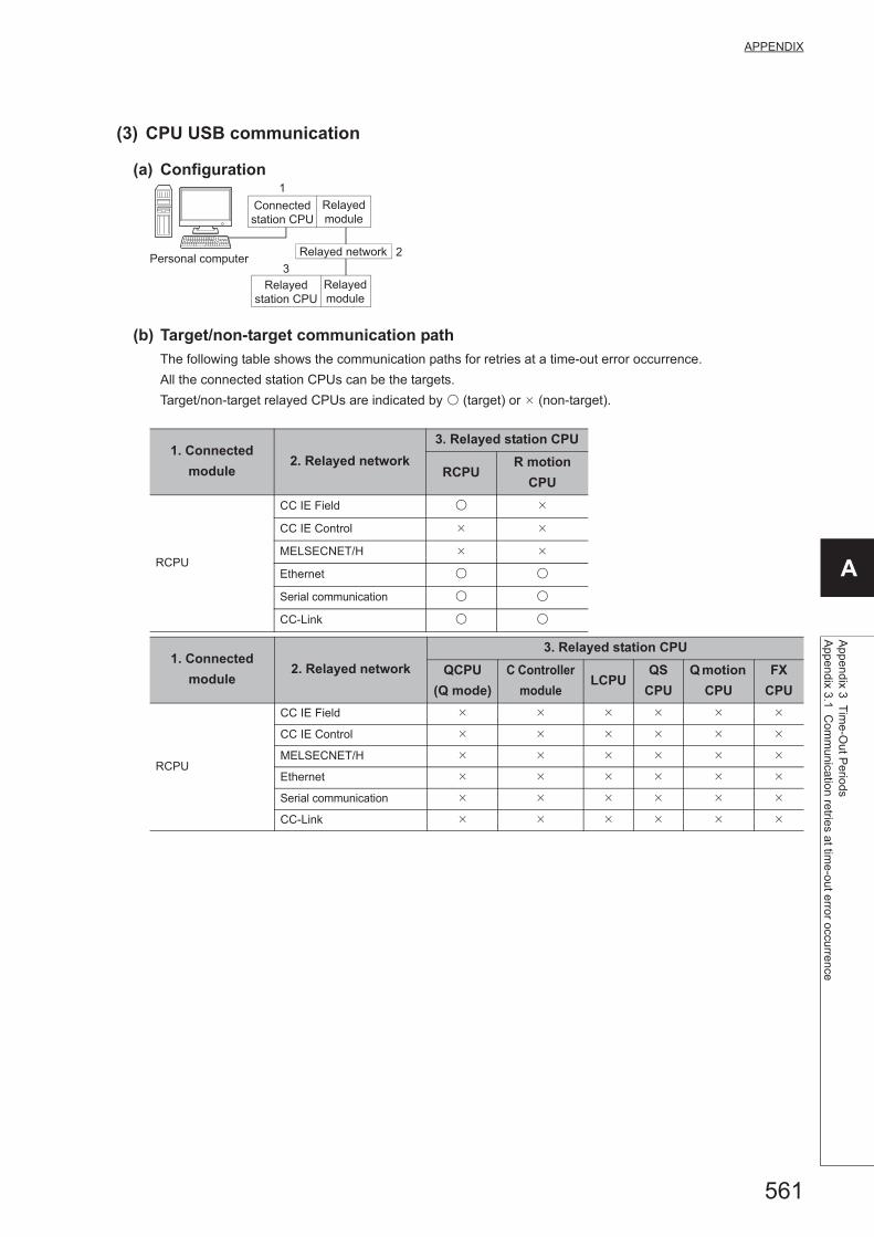
561
APPENDIX
A
Appendix 3 T
ime-O
ut Periods
Appendix 3.1 C
omm
unication retrie
s at time-out error occurrence
(3) CPU USB communication
(a) Configuration
(b) Target/non-target communication path
The following table shows the communication paths for retries at a time-out error occurrence.
All the connected station CPUs can be the targets.
Target/non-target relayed CPUs are indicated by (target) or (non-target).
1. Connected
module2. Relayed network
3. Relayed station CPU
RCPUR motion
CPU
RCPU
CC IE Field
CC IE Control
MELSECNET/H
Ethernet
Serial communication
CC-Link
1. Connected
module2. Relayed network
3. Relayed station CPU
QCPU
(Q mode)
C Controller
moduleLCPU
QS
CPU
Q motion
CPU
FX
CPU
RCPU
CC IE Field
CC IE Control
MELSECNET/H
Ethernet
Serial communication
CC-Link
Personal computer
Connected
station CPU
Relayed
module
Relayed network
Relayed
station CPU
Relayed
module
1
2
3

562
1. Connected
module2. Relayed network
3. Relayed station CPU
RCPUR motion
CPU
QCPU (Q mode)
CC IE Field
CC IE Control
MELSECNET/H
Ethernet
Serial communication
CC-Link
1. Connected
module2. Relayed network
3. Relayed station CPU
QCPU
(Q mode)
C Controller
moduleLCPU
QS
CPU
Q motion
CPU
FX
CPU
QCPU (Q mode)
CC IE Field
CC IE Control
MELSECNET/H
Ethernet
Serial communication
CC-Link
1. Connected
module2. Relayed network
3. Relayed station CPU
RCPUR motion
CPU
C Controller module
CC IE Field
CC IE Control
MELSECNET/H
Ethernet
Serial communication
CC-Link
1. Connected
module2. Relayed network
3. Relayed station CPU
QCPU
(Q mode)
C Controller
moduleLCPU
QS
CPU
Q motion
CPU
FX
CPU
C Controller module
CC IE Field
CC IE Control
MELSECNET/H
Ethernet
Serial communication
CC-Link
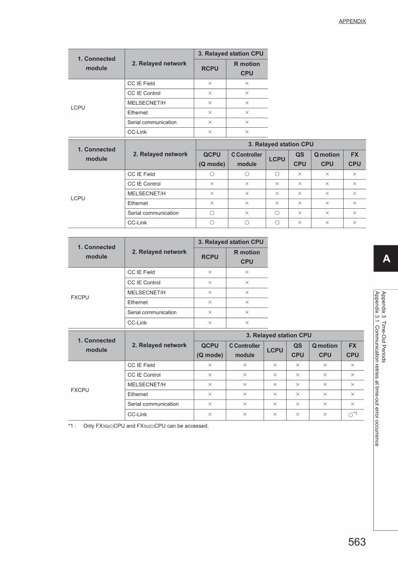
563
APPENDIX
A
Appendix 3 T
ime-O
ut Periods
Appendix 3.1 C
omm
unication retrie
s at time-out error occurrence
*1 : Only FX3G(C)CPU and FX3U(C)CPU can be accessed.
1. Connected
module2. Relayed network
3. Relayed station CPU
RCPUR motion
CPU
LCPU
CC IE Field
CC IE Control
MELSECNET/H
Ethernet
Serial communication
CC-Link
1. Connected
module2. Relayed network
3. Relayed station CPU
QCPU
(Q mode)
C Controller
moduleLCPU
QS
CPU
Q motion
CPU
FX
CPU
LCPU
CC IE Field
CC IE Control
MELSECNET/H
Ethernet
Serial communication
CC-Link
1. Connected
module2. Relayed network
3. Relayed station CPU
RCPUR motion
CPU
FXCPU
CC IE Field
CC IE Control
MELSECNET/H
Ethernet
Serial communication
CC-Link
1. Connected
module2. Relayed network
3. Relayed station CPU
QCPU
(Q mode)
C Controller
moduleLCPU
QS
CPU
Q motion
CPU
FX
CPU
FXCPU
CC IE Field
CC IE Control
MELSECNET/H
Ethernet
Serial communication
CC-Link *1

564
(4) CC-Link G4 communication
(a) Configuration
(b) Target/non-target communication path
The following tables show the communication paths for retries at a time-out error occurrence.
All the connected station CPUs can be the targets.
Target/non-target relayed CPUs are indicated by (target) or (non-target).
When CC-Link G4-S3 module is Q mode and connected station CPU is QCPU (Q mode) or C Controller
module
1. Connected
module2. Relayed network
3. Relayed station CPU
RCPUR motion
CPU
QCPU (Q mode)
CC IE Field
CC IE Control
MELSECNET/H
Ethernet
Serial communication
CC-Link
1. Connected
module2. Relayed network
3. Relayed station CPU
QCPU
(Q mode)
C Controller
moduleLCPU
QS
CPU
Q motion
CPU
FX
CPU
QCPU (Q mode)
CC IE Field
CC IE Control
MELSECNET/H
Ethernet
Serial communication
CC-Link
2
Connected
station CPU
CC-Link
module
Relayed
module
Relayed network
Relayed
station CPU
Relayed
module
1
3
Personal computer
CC-Link G4
module

565
APPENDIX
A
Appendix 3 T
ime-O
ut Periods
Appendix 3.1 C
omm
unication retrie
s at time-out error occurrence
When CC-Link G4-S3 module is Q mode and connected station CPU is LCPU
1. Connected
module2. Relayed network
3. Relayed station CPU
RCPUR motion
CPU
C Controller module
CC IE Field
CC IE Control
MELSECNET/H
Ethernet
Serial communication
CC-Link
1. Connected
module2. Relayed network
3. Relayed station CPU
QCPU
(Q mode)
C Controller
moduleLCPU
QS
CPU
Q motion
CPU
FX
CPU
C Controller module
CC IE Field
CC IE Control
MELSECNET/H
Ethernet
Serial communication
CC-Link
1. Connected
module2. Relayed network
3. Relayed station CPU
RCPUR motion
CPU
LCPU
CC IE Field
CC IE Control
MELSECNET/H
Ethernet
Serial communication
CC-Link
1. Connected
module2. Relayed network
3. Relayed station CPU
QCPU
(Q mode)
C Controller
moduleLCPU
QS
CPU
Q motion
CPU
FX
CPU
LCPU
CC IE Field
CC IE Control
MELSECNET/H
Ethernet
Serial communication
CC-Link

566
(5) Modem communication
(a) When using FXCPU
Configuration
Target/non-target communication path
The following table shows the communication paths for retries at a time-out error occurrence.
All the connected station CPUs can be the targets.
Target/non-target relayed CPUs are indicated by (target) or (non-target).
1. Connected
module2. Relayed network
3. Relayed station CPU
RCPUR motion
CPU
FXCPU
CC IE Field
CC IE Control
MELSECNET/H
Ethernet
Serial communication
CC-Link
1. Connected
module2. Relayed network
3. Relayed station CPU
QCPU
(Q mode)
C Controller
moduleLCPU
QS
CPU
Q motion
CPU
FX
CPU
FXCPU
CC IE Field
CC IE Control
MELSECNET/H
Ethernet
Serial communication
CC-Link
Connected
station CPU
Relayed
module
Relayed network
Relayed
station CPU
Relayed
module
Personal computer
Modem
Subscriber's line
Modem
1
2
3

567
APPENDIX
A
Appendix 3 T
ime-O
ut Periods
Appendix 3.1 C
omm
unication retrie
s at time-out error occurrence
(b) When using Q series-compatible C24 or QC24N
Configuration
Target/non-target communication path
The following table shows the communication paths for retries at a time-out error occurrence.
All the connected station CPUs can be the targets.
Target/non-target relayed CPUs are indicated by (target) or (non-target).
Connected station3. Relayed
network
4. Relayed station CPU
1. CPU2. Connected
moduleRCPU
R motion
CPU
QCPU
(Q mode)
Q series-
compatible C24
CC IE Field
CC IE Control
MELSECNET/H
Ethernet
Serial communication
CC-Link
Multi-drop connection
(Independent mode)
Connected station3. Relayed
network
4. Relayed station CPU
1. CPU2. Connected
module
QCPU
(Q mode)
C Controller
moduleLCPU
QS
CPU
Q motion
CPU
FX
CPU
QCPU
(Q mode)
Q series-
compatible C24
CC IE Field
CC IE Control
MELSECNET/H
Ethernet
Serial communication
CC-Link
Multi-drop connection
(Independent mode)
Connected
station CPU
Relayed
module
Relayed network
Relayed
station CPU
Relayed
module
Personal computer
Modem
Subscriber's line
Modem
1
3
4
Connected
module
2
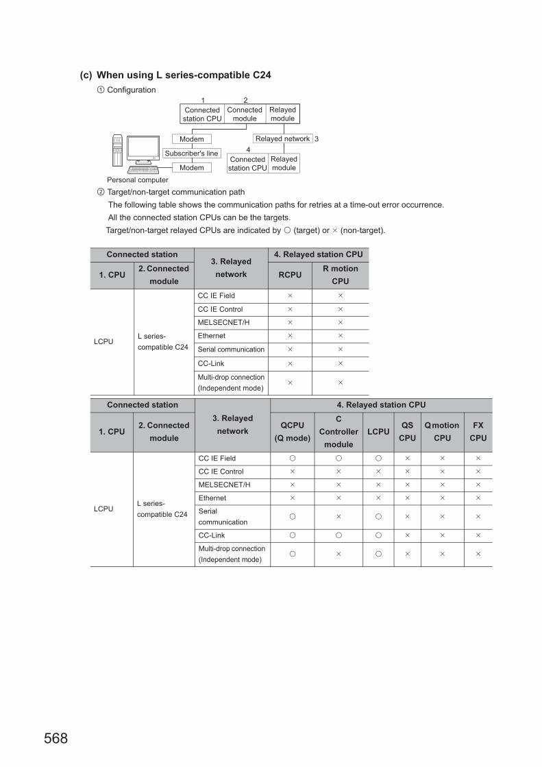
568
(c) When using L series-compatible C24
Configuration
Target/non-target communication path
The following table shows the communication paths for retries at a time-out error occurrence.
All the connected station CPUs can be the targets.
Target/non-target relayed CPUs are indicated by (target) or (non-target).
Connected station3. Relayed
network
4. Relayed station CPU
1. CPU2. Connected
moduleRCPU
R motion
CPU
LCPUL series-
compatible C24
CC IE Field
CC IE Control
MELSECNET/H
Ethernet
Serial communication
CC-Link
Multi-drop connection
(Independent mode)
Connected station
3. Relayed
network
4. Relayed station CPU
1. CPU2. Connected
module
QCPU
(Q mode)
C
Controller
module
LCPUQS
CPU
Q motion
CPU
FX
CPU
LCPUL series-
compatible C24
CC IE Field
CC IE Control
MELSECNET/H
Ethernet
Serial
communication
CC-Link
Multi-drop connection
(Independent mode)
Connected
station CPU
Relayed
module
Relayed network
Connected
station CPU
Relayed
module
Personal computer
Modem
Subscriber's line
Modem
1
3
4
Connected
module
2

569
APPENDIX
A
Appendix 3 T
ime-O
ut Periods
Appendix 3.2 C
omm
unication retrie
s at receive data error o
ccurrence
Appendix 3.2 Communication retries at receive data error occurrence
If a receive data error occurs during communication, send/receive retry processing may be repeated for a maximum of
three times in the ACT control.
At that time, the process takes a maximum of three times longer period than the set time-out value which is a period
until the normal or abnormal termination of the function.
The following shows communication paths for retries at a receive data error occurrence.
(1) Ethernet communication
(a) Configuration
(b) Target/non-target communication path
The following table shows the communication paths for retries at a data error occurrence.
All the connected station CPUs can be the targets.
Target/non-target relayed CPUs are indicated by (target) or (non-target).
Connected station3. Relayed
network
4. Relayed station CPU
1. CPU2. Connected
moduleRCPU
R motion
CPU
RCPU
R series-
compatible E71,
RCPU
CC IE Field
CC IE Control
MELSECNET/H
Ethernet
Serial communication
CC-Link
Connected station3. Relayed
network
4. Relayed station CPU
1. CPU2. Connected
module
QCPU
(Q mode)
C Controller
moduleLCPU
QS
CPU
Q motion
CPU
FX
CPU
RCPU
R series-
compatible E71,
RCPU
CC IE Field
CC IE Control
MELSECNET/H
Ethernet
Serial communication
CC-Link
Personal computer
Connected
station CPU
Connected
module
Relayed
module
Relayed network
Relayed
station CPU
Relayed
module
1 2
3
4
Ethernet

570
Connected station3. Relayed
network
4. Relayed station CPU
1. CPU2. Connected
moduleRCPU
R motion
CPU
FX5CPU FX5CPU
CC IE Field
CC IE Control
MELSECNET/H
Ethernet
Serial communication
CC-Link
Connected station3. Relayed
network
4. Relayed station CPU
1. CPU2. Connected
module
QCPU
(Q mode)
C Controller
moduleLCPU
QS
CPU
Q motion
CPU
FX
CPU
FX5CPU FX5CPU
CC IE Field
CC IE Control
MELSECNET/H
Ethernet
Serial communication
CC-Link
Connected station3. Relayed
network
4. Relayed station CPU
1. CPU2. Connected
moduleRCPU
R motion
CPU
QCPU
(Q mode)
Q series-
compatible E71,
Built-in Ethernet
port QCPU
CC IE Field
CC IE Control
MELSECNET/H
Ethernet
Serial communication
CC-Link
Connected station3. Relayed
network
4. Relayed station CPU
1. CPU2. Connected
module
QCPU
(Q mode)
C Controller
moduleLCPU
QS
CPU
Q motion
CPU
FX
CPU
QCPU
(Q mode)
Q series-
compatible E71,
Built-in Ethernet
port QCPU
CC IE Field
CC IE Control
MELSECNET/H
Ethernet
Serial communication
CC-Link

571
APPENDIX
A
Appendix 3 T
ime-O
ut Periods
Appendix 3.2 C
omm
unication retrie
s at receive data error o
ccurrence
Connected station3. Relayed
network
4. Relayed station CPU
1. CPU2. Connected
moduleRCPU
R motion
CPU
LCPUBuilt-in Ethernet
port LCPU
CC IE Field
CC IE Control
MELSECNET/H
Ethernet
Serial communication
CC-Link
Connected station
3. Relayed
network
4. Relayed station CPU
1. CPU2. Connected
module
QCPU
(Q mode)
C
Controller
module
LCPUQS
CPU
Q motion
CPU
FX
CPU
LCPUBuilt-in Ethernet
port LCPU
CC IE Field
CC IE Control
MELSECNET/H
Ethernet
Serial communication
CC-Link

572
Appendix 3.3 Time-out errors at fixed time in ACT control
MX Component performs communication to check whether a personal computer and a programmable controller
system are connected normally before executing the Open function.
When performing the above communication, the fixed time-out period (1000ms to 4500ms) in the ACT control is used.
Note that if an error occurs during the above communication, an error other than the time-out error may occur.
The following shows communication paths for a time-out error occurrence at the fixed time in the ACT control.
(1) Serial communication
(a) Configuration
(b) Target/non-target communication path
The following table shows the communication paths for a time-out error occurrence at the fixed time in the ACT
control.
All the connected station CPUs can be the targets.
Target/non-target relayed CPUs are indicated by (target) or (non-target).
Connected station3. Relayed
network
4. Relayed station CPU
1. CPU2. Connected
moduleRCPU
R motion
CPU
RCPUR series-
compatible C24
CC IE Field
CC IE Control
MELSECNET/H
Ethernet
Serial communication
CC-Link
Multi-drop connection
Connected station3. Relayed
network
4. Relayed station CPU
1. CPU2. Connected
module
QCPU
(Q mode)
C Controller
moduleLCPU
QS
CPU
Q motion
CPU
FX
CPU
RCPUR series-
compatible C24
CC IE Field
CC IE Control
MELSECNET/H
Ethernet
Serial communication
CC-Link
Multi-drop connection
Personal computer
Connected
station CPU
Connected
module
Relayed
module
Relayed network
Relayed
station CPU
Relayed
module
1 2
3
4

573
APPENDIX
A
Appendix 3 T
ime-O
ut Periods
Appendix 3.3 T
ime-o
ut errors at fixed time in A
CT
control
Connected station3. Relayed
network
4. Relayed station CPU
1. CPU2. Connected
moduleRCPU
R motion
CPU
QCPU
(Q mode)
Q series-
compatible C24
CC IE Field
CC IE Control
MELSECNET/H
Ethernet
Serial communication
CC-Link
Multi-drop connection
Connected station3. Relayed
network
4. Relayed station CPU
1. CPU2. Connected
module
QCPU
(Q mode)
C Controller
moduleLCPU
QS
CPU
Q motion
CPU
FX
CPU
QCPU
(Q mode)
Q series-
compatible C24
CC IE Field
CC IE Control
MELSECNET/H
Ethernet
Serial communication
CC-Link
Multi-drop connection
Connected station3. Relayed
network
4. Relayed station CPU
1. CPU2. Connected
moduleRCPU
R motion
CPU
LCPUL series-
compatible C24
CC IE Field
CC IE Control
MELSECNET/H
Ethernet
Serial communication
CC-Link
Multi-drop connection
Connected station3. Relayed
network
4. Relayed station CPU
1. CPU2. Connected
module
QCPU
(Q mode)
C Controller
moduleLCPU
QS
CPU
Q motion
CPU
FX
CPU
LCPUL series-
compatible C24
CC IE Field
CC IE Control
MELSECNET/H
Ethernet
Serial communication
CC-Link
Multi-drop connection

574
(2) CPU COM communication
(a) Configuration
(b) Target/non-target communication path
The following table shows the communication paths for a time-out error occurrence at the fixed time in the ACT
control.
All the connected station CPUs can be the targets.
Target/non-target relayed CPUs are indicated by (target) or (non-target).
1. Connected
module2. Relayed network
3. Relayed station CPU
RCPUR motion
CPU
FX5CPU
CC IE Field
CC IE Control
MELSECNET/H
Ethernet
Serial communication
CC-Link
1. Connected
module2. Relayed network
3. Relayed station CPU
QCPU
(Q mode)
C Controller
moduleLCPU
QS
CPU
Q motion
CPU
FX
CPU
FX5CPU
CC IE Field
CC IE Control
MELSECNET/H
Ethernet
Serial communication
CC-Link
Personal computer
Connected
station CPU
Relayed
module
Relayed network
Relayed
station CPU
Relayed
module
1
2
3

575
APPENDIX
A
Appendix 3 T
ime-O
ut Periods
Appendix 3.3 T
ime-o
ut errors at fixed time in A
CT
control
1. Connected
module2. Relayed network
3. Relayed station CPU
RCPUR motion
CPU
QCPU (Q mode),
C Controller module
CC IE Field
CC IE Control
MELSECNET/H
Ethernet
Serial communication
CC-Link
1. Connected
module2. Relayed network
3. Relayed station CPU
QCPU
(Q mode)
C Controller
moduleLCPU
QS
CPU
Q motion
CPU
FX
CPU
QCPU (Q mode),
C Controller module
CC IE Field
CC IE Control
MELSECNET/H
Ethernet
Serial communication
CC-Link
1. Connected
module2. Relayed network
3. Relayed station CPU
RCPUR motion
CPU
LCPU
CC IE Field
CC IE Control
MELSECNET/H
Ethernet
Serial communication
CC-Link
1. Connected
module2. Relayed network
3. Relayed station CPU
QCPU
(Q mode)
C Controller
moduleLCPU
QS
CPU
Q motion
CPU
FX
CPU
LCPU
CC IE Field
CC IE Control
MELSECNET/H
Ethernet
Serial communication
CC-Link

576
*1 : Only FX3G(C)CPU and FX3U(C)CPU can be accessed.
1. Connected
module2. Relayed network
3. Relayed station CPU
RCPUR motion
CPU
FXCPU
CC IE Field
CC IE Control
MELSECNET/H
Ethernet
Serial communication
CC-Link
1. Connected
module2. Relayed network
3. Relayed station CPU
QCPU
(Q mode)
C
Controller
module
LCPUQS
CPU
Q motion
CPU
FX
CPU
FXCPU
CC IE Field
CC IE Control
MELSECNET/H
Ethernet
Serial communication
CC-Link *1

577
APPENDIX
A
Appendix 3 T
ime-O
ut Periods
Appendix 3.3 T
ime-o
ut errors at fixed time in A
CT
control
(3) CC-Link G4 communication
(a) Configuration
(b) Target/non-target communication path
The following table shows the communication paths for a time-out error occurrence at the fixed time in the ACT
control.
All the connected station CPUs can be the targets.
Target/non-target relayed CPUs are indicated by (target) or (non-target).
1. Connected
module2. Relayed network
3. Relayed station CPU
RCPUR motion
CPU
QCPU (Q mode)
CC IE Field
CC IE Control
MELSECNET/H
Ethernet
Serial communication
CC-Link
1. Connected
module2. Relayed network
3. Relayed station CPU
QCPU
(Q mode)
C Controller
moduleLCPU
QS
CPU
Q motion
CPU
FX
CPU
QCPU (Q mode)
CC IE Field
CC IE Control
MELSECNET/H
Ethernet
Serial communication
CC-Link
2
Connected
station CPU
CC-Link
module
Relayed
module
Relayed network
Relayed
station CPU
Relayed
module
1
3
Personal computer
CC-Link
G4 module

578
1. Connected
module2. Relayed network
3. Relayed station CPU
RCPUR motion
CPU
C Controller module
CC IE Field
CC IE Control
MELSECNET/H
Ethernet
Serial communication
CC-Link
1. Connected
module2. Relayed network
3. Relayed station CPU
QCPU
(Q mode)
C Controller
moduleLCPU
QS
CPU
Q motion
CPU
FX
CPU
C Controller module
CC IE Field
CC IE Control
MELSECNET/H
Ethernet
Serial communication
CC-Link
1. Connected
module2. Relayed network
3. Relayed station CPU
RCPUR motion
CPU
LCPU
CC IE Field
CC IE Control
MELSECNET/H
Ethernet
Serial communication
CC-Link
1. Connected
module2. Relayed network
3. Relayed station CPU
QCPU
(Q mode)
C Controller
moduleLCPU
QS
CPU
Q motion
CPU
FX
CPU
LCPU
CC IE Field
CC IE Control
MELSECNET/H
Ethernet
Serial communication
CC-Link

579
REVISIONS
*The manual number is given on the bottom left of the back cover.
Print date *Manual number Revision
Jul., 2012 SH-081085ENG-A First edition
Feb., 2013 SH-081085ENG-B
Q03UDV, Q04UDV, Q06UDV, Q13UDV, Q26UDV, Q24DHCCPU-V, FX3GC
OPERATING CONSIDERATIONS, TERMS, Section 1.1, Section 2.1.3, Section 2.3,
Section 2.4, Section 3.2, Section 4.2 to 4.10, Section 4.13, Section 4.15,
Section 5.2.11 to 5.2.14, Section 5.2.23, Section 5.2.24, Section 5.2.26, Section 5.3.11,
Section 5.3.12, Section 5.3.24, Section 5.3.25, Section 7.1, Appendix 3
Appendix 4
Aug., 2013 SH-081085ENG-C
L02S, L06, L26
Section 2.2.5,Section 4.3.9, Section 4.3.10, Section 4.13, Section 4.16.13,
Section 4.16.14, Section 6.6, Section 6.6.1
OPERATING CONSIDERATIONS, TERMS, Section 1.1, Section 1.2.1, Section 2.1.3,
Section 2.2.1 to Section 2.2.4, Section 3.2, Section 4.1, Section 4.3.1 to Section 4.3.4,
Section 4.4.4, Section 4.5.5, Section 4.16.1, Section 4.16.2, Section 4.16.15, CHAPTER 5,
Section 5.2.1 to Section 5.2.26, Section 5.3.1 to Section 5.3.26, CHAPTER 6, Section 7.1,
Appendix 2, Appendix 3.1, Appendix 3.2, Appendix 3.3
Dec., 2013 SH-081085ENG-D
FX3S, Q12DC-V (Extended mode), Q24DHC-LS, GOT2000, A800
Section 4.4.5, Section 4.5.6
RELATED MANUALS, TERMS, Section 1.1, Section 2.3, Section 2.4, Section 3.1, Section 3.2,
Section 4.2.1, Section 4.2.2, Section 4.3.1 to Section 4.3.10, Section 4.4.1, Section 4.4.2,
Section 4.4.4, Section 4.5.1, Section 4.5.2, Section 4.6 to Section 4.10, Section 4.14.1,
Section 4.14.2, Section 4.16, Section 4.16.1 to Section 4.16.17, Section 5.1,
Section 5.2.3 to Section 5.2.26, Section 7.1
Model Addition
Correction
Deletion
Model Addition
Addition
Correction
Model Addition
Addition
Correction

580
Japanese Manual Version SH-081083-G
© 2012 MITSUBISHI ELECTRIC CORPORATION
May, 2014 SH-081085ENG-E
R04, R08, R16, R32, R120, R16MT, R32MT
TERMS, Section 1.1, Section 2.3, Section 3.2, CHAPTER 4, CHAPTER 5, CHAPTER 6,
Appendix 3
Dec., 2014 SH-081085ENG-F
CR750-D/CRnD-700 series
Section 4.3.15, Section 4.4.6, Section 4.5.9
TERMS, Section 1.1, Section 1.2.1, Section 2.1.3, Section 2.3, Section 3.2, Section 5.1, Section 5.2.3 to Section 5.2.23, Section 5.2.26, Section 5.3.3 to Section 5.3.8, Section 5.3.18 to Section 5.3.23, Section 7.1, Section 7.2
Apr., 2015 SH-081085ENG-GSection 4.3.7, Section 4.3.8, Section 4.4.1
TERMS, Section 1.1, Section 2.3, Section 3.2, Section 5.2.9 to Section 5.2.14, Appendix 3.1, Appendix 3.2, Appendix 3.3
This manual confers no industrial rights or any rights of any other kind, nor does it confer any patent licenses.
Mitsubishi Electric Corporation cannot be held responsible for any problems involving industrial property rights which may
occur as a result of using the contents noted in this manual.
Print date *Manual number Revision
Model Addition
Correction
Model Addition
Addition
Correction
Addition
Correction

581
WARRANTYPlease confirm the following product warranty details before using this product.
1. Gratis Warranty Term and Gratis Warranty Range
If any faults or defects (hereinafter "Failure") found to be the responsibility of Mitsubishi occurs during use of the product within the gratis warranty term, the product shall be repaired at no cost via the sales representative or Mitsubishi Service Company.However, if repairs are required onsite at domestic or overseas location, expenses to send an engineer will be solely at the customer's discretion. Mitsubishi shall not be held responsible for any re-commissioning, maintenance, or testing on-site that involves replacement of the failed module.[Gratis Warranty Term]The gratis warranty term of the product shall be for one year after the date of purchase or delivery to a designated place.Note that after manufacture and shipment from Mitsubishi, the maximum distribution period shall be six (6) months, and the longest gratis warranty term after manufacturing shall be eighteen (18) months. The gratis warranty term of repair parts shall not exceed the gratis warranty term before repairs.[Gratis Warranty Range](1) The range shall be limited to normal use within the usage state, usage methods and usage environment, etc.,
which follow the conditions and precautions, etc., given in the instruction manual, user's manual and caution labels on the product.
(2) Even within the gratis warranty term, repairs shall be charged for in the following cases.1. Failure occurring from inappropriate storage or handling, carelessness or negligence by the user. Failure
caused by the user's hardware or software design.2. Failure caused by unapproved modifications, etc., to the product by the user.3. When the Mitsubishi product is assembled into a user's device, Failure that could have been avoided if
functions or structures, judged as necessary in the legal safety measures the user's device is subject to or as necessary by industry standards, had been provided.
4. Failure that could have been avoided if consumable parts (battery, backlight, fuse, etc.) designated in the instruction manual had been correctly serviced or replaced.
5. Failure caused by external irresistible forces such as fires or abnormal voltages, and Failure caused by force majeure such as earthquakes, lightning, wind and water damage.
6. Failure caused by reasons unpredictable by scientific technology standards at time of shipment from Mitsubishi.
7. Any other failure found not to be the responsibility of Mitsubishi or that admitted not to be so by the user.
2. Onerous repair term after discontinuation of production
(1) Mitsubishi shall accept onerous product repairs for seven (7) years after production of the product is discontinued.Discontinuation of production shall be notified with Mitsubishi Technical Bulletins, etc.
(2) Product supply (including repair parts) is not available after production is discontinued.
3. Overseas service
Overseas, repairs shall be accepted by Mitsubishi's local overseas FA Center. Note that the repair conditions at each FA Center may differ.
4. Exclusion of loss in opportunity and secondary loss from warranty liability
Regardless of the gratis warranty term, Mitsubishi shall not be liable for compensation of damages caused by any cause found not to be the responsibility of Mitsubishi, loss in opportunity, lost profits incurred to the user by Failures of Mitsubishi products, special damages and secondary damages whether foreseeable or not, compensation for accidents, and compensation for damages to products other than Mitsubishi products, replacement by the user, maintenance of on-site equipment, start-up test run and other tasks.
5. Changes in product specifications
The specifications given in the catalogs, manuals or technical documents are subject to change without prior notice.

582
Microsoft, Windows, Windows XP, Windows Vista, Access, Excel, Visual Basic, Visual C++, Visual C#, Visual Studio are
trademarks or registered trademarks of Microsoft Corporation in the United States and other countries.
Ethernet is a trademark or registered trademark of Xerox Corporation.
All other company names and product names used in this manual are trademarks or registered trademarks of their
respective companies.
SPREAD
Copyright (C) 2004 FarPoint Technologies, Inc.


SH(NA)-081085ENG-G(1504)KWIX
MODEL: SW4DNC-ACT-P-E
MODEL CODE: 13JW12
Specifications subject to change without notice.
When exported from Japan, this manual does not require application to theMinistry of Economy, Trade and Industry for service transaction permission.
HEAD OFFICE : TOKYO BUILDING, 2-7-3 MARUNOUCHI, CHIYODA-KU, TOKYO 100-8310, JAPANNAGOYA WORKS : 1-14 , YADA-MINAMI 5-CHOME , HIGASHI-KU, NAGOYA , JAPAN