mx.yamaha.com · 2020. 8. 3. · 2 special notices • the software and this user guide are the...
TRANSCRIPT
Console File Converter User Guide
Rev.5.2
2
Special Notices
• The software and this user guide are the exclusive copyrights of Yamaha Corporation.
• Copying of the software or reproduction of this user guide in whole or in part by any means is expressly forbidden without the written consent of the manufacturer.
• Copying of the commercially available music sequence data and/or digital audio files is strictly prohibited except for your personal use.
• Yamaha makes no representations or warranties with regard to the use of the software and documentation and cannot be held responsible for the results of the use of this user guide and the software.
• The screen displays as illustrated in this user guide are for instructional purposes, and may appear somewhat different from the screens which appear on your computer.
• For information on modification of system software, certain functions, or specifications due to version update of the application, please visit the following website: https://www.yamahaproaudio.com/
• Windows is a registered trademark of Microsoft Corporation in the U.S. and other countries.
• The company names and product names in this user guide are the trademarks or registered trademarks of their respective companies. Contents 1. Introduction ............................................................................................ 3
1.1. Overview .............................................................................................. 3 1.2. Supported models ................................................................................. 3
2. Conversion procedure ............................................................................. 4 2.1. Procedure overview............................................................................... 4 2.2. <Step1> Source file preparation ............................................................. 4 2.3. <Step2> Execute Console File Converter ................................................ 5 2.4. <Step3> Edit converted file .................................................................... 6
3. Reference ............................................................................................... 7 3.1. Conversion Options ............................................................................... 7 3.2. Conversion between PM5D and M7CL .................................................. 10
Channel matching ................................................................................................. 10 Conversion Overview –between PM5D and M7CL .................................................... 10 Library link – HA & Channel Name (in Input Patch/Output Patch libraries) ................... 13
3.3. Conversion between PM5D and CL/QL ................................................. 15 Channel matching ................................................................................................. 15 Conversion Overview –between PM5D and CL/QL ................................................... 15
3.4. Conversion between M7CL and LS9 ..................................................... 19 Channel matching ................................................................................................. 19
File Converter matches both models’ channels as shown below. ........................................... 19 Conversion Overview –between M7CL and LS9 ....................................................... 19
3.5. Conversion between M7CL and CL/QL ................................................. 21 Channel matching ................................................................................................. 21 Conversion Overview –between M7CL and CL/QL ................................................... 21
3.6. Conversion between LS9 and CL/QL .................................................... 24 Channel matching ................................................................................................. 24 Conversion Overview –between LS9 and CL/QL ...................................................... 24
3.7. Conversion between RIVAGE PM and CL/QL ........................................ 27 Channel matching ................................................................................................. 27 Conversion Overview –between RIVAGE PM and CL/QL .......................................... 27
3.8. “Recall Filter” Treatment ...................................................................... 31
3
1. Introduction 1.1. Overview
This Console File Converter converts common parameters between different models. But because of different specifications among the models, there are some parameters which cannot be directly converted. These parameters are given a default setting or substitute setting. Here is the compatibility overview
Parameters which are converted: - Input channel parameters (e.g. HA (except for RIVAGE PM), Fader, On, EQ, Dynamics etc.) - Output channel parameters (e.g. Fader, On, EQ, Dynamics etc.) - Input channel names / Output channel names - Effect parameters
This converter converts the above data from the libraries, Current scenes, and scenes in the Scene list in the each library list. Data in the CL/QL Dante Input Patch library, and the PM5D GEQ library is not converted.
Parameters which are not converted:
- Patch setting - Monitor setting - Wordclock, digital I/O setting - MIDI / Remote Control setting - Customisation setting (e.g. User Defined keys)
After conversion, parameters which are filled by their default value, and the global setup, may need to be edited manually.
Please refer to compatibility details listed in section “3.Reference”.
1.2. Supported models
Console File Converter supports the data formats of the following five console series.
PM5D series M7CL series LS9 series CL/QL series RIVAGE PM series PM5D V2 PM5D-RH V2 DSP5D
M7CL-32 V3.5 M7CL-48 V3.5 M7CL-48ES V3.5
LS9-16 LS9-32
CL5 CL3 CL1 QL5 QL1
PM10 PM7 PM5 PM3
Conversions are supported between the following model pairs. - PM5D series and M7CL series - M7CL series and LS9 series - CL/QL series and PM5D series - CL/QL series and M7CL series - CL/QL series and LS9 series - RIVAGE PM series and CL/QL series
However, some data formats created by certain versions of the firmware and editor are not supported. For the latest information about the supported versions, refer to the Yamaha Pro Audio Website (https://www.yamahaproaudio.com/).
4
2. Conversion procedure 2.1. Procedure overview There are three steps to convert a console file. Step1: Prepare the source file for desired result
Step2: Conversion with Console File Converter Step3: Edit initialized parameters of the converted file
This section explains the conversion procedure step by step.
2.2. <Step1> Source file preparation There are two options for preparing the source Console File*
(*Console File is a file format which can be saved/loaded by both console and Studio Manager. Console models have their own file extension such as .pm5, .m7c, .ls9, .clf.)
- Save on console
Save the source data to Compact Flash card (PM5D) or USB flash drive (M7CL, LS9, CL, QL, RIVAGE PM).
- Save on computer with Studio Manager or each Editor
Synchronise the console with Studio Manager, CL Editor, QL Editor or RIVAGE Editor and save the data by “Save Session” function. Saved file type should be Console File (.pm5, .m7c, .ls9, .clf, .pm10all, .pm10part, .pm7all, .pm7part, .rivagepm), not Editor File (.yse, .cle).
Important
- Scenes with a number higher than 300 in PM5D cannot be converted: first move them to locations below 300. When converting from the RIVAGE PM to other models, scenes are converted consecutively from number 1 up to 300.
- This converter can convert multiple Scenes from the Scene library. Please note that
conversions are executed under the assumption of sequential recall from the smallest number in a conversion target range to the largest number, while considering “Recall Filtering” (e.g. Recall Safe, Selective Recall/Focus) and library link functions (e.g. HA library, In/Out Patch library).
- Many libraries include read-only presets, with the number varying by model. Conversion cannot be performed if there is already a preset value in the conversion destination. Therefore, move any required library entries in advance, to a number compatible with the target console. For more information, refer to the “Library Conversion Table.3.1”
- You may need to re-arrange Recall Safe, Selective Recall/Focus, Current Scene and the order of the source Scenes on the console, Studio Manager, or each Editor in advance. Please refer to section “3.Reference” for further information.
- RIVAGE PM series data is compatible, file conversion is unnecessary.
5
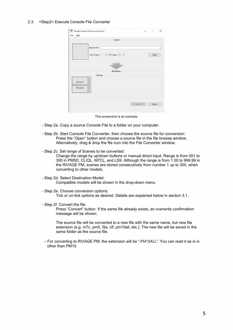
2.3. <Step2> Execute Console File Converter
This screenshot is an example. - Step 2a. Copy a source Console File to a folder on your computer.
- Step 2b. Start Console File Converter, then choose the source file for conversion:
Press the “Open” button and choose a source file in the file browse window. Alternatively, drag & drop the file icon into the File Converter window.
- Step 2c. Set range of Scenes to be converted: Change the range by up/down buttons or manual direct input. Range is from 001 to 300 in PM5D, CL/QL, M7CL, and LS9. Although the range is from 1.00 to 999.99 in the RIVAGE PM, scenes are stored consecutively from number 1 up to 300, when converting to other models.
- Step 2d. Select Destination Model: Compatible models will be shown in the drop-down menu.
- Step 2e. Choose conversion options: Tick or un-tick options as desired. Details are explained below in section 3.1. - Step 2f. Convert the file.
Press “Convert” button. If the same file already exists, an overwrite confirmation message will be shown. The source file will be converted to a new file with the same name, but new file extension (e.g. m7c, pm5, l9a, clf, pm10all, etc.). The new file will be saved in the same folder as the source file.
- For converting to RIVAGE PM, the extension will be “.PM10ALL”. You can read it as is in
other than PM10.
6
2.4. <Step3> Edit converted file
When converted files are loaded, some parameters (e.g. Pair/Channel Link, Patch, Wordclock) are given their default setting or a substitute setting. Before starting to mix, such parameters may need editing. Here is an example:
- Step 3a. Load the converted file into destination console, Studio Manager, CL Editor, QL Editor, or RIVAGE PM Editor.
Tips
Specific libraries and scenes can be loaded individually.
- Open the required scene or library from the Scene window or Library window on the CL Editor or QL Editor.
- Load the required scene or library on the LOAD SELECT window.
- Load the required scene or library from a USB flash drive on the CL/QL/RIVAGE PM LOAD SELECT window.
- Load the required scene or library from a memory card on the PM5D LOAD window.
- Load the converted file into Studio Manager, then on the SCENE window or LIBRARY window, save the required individual scene or library. Synchronise with the LS9/M7CL/PM5D, and load the scene or library when ready.
- Step 3b. After recalling the first Scene in the conversion range, edit Input Patch and Output Patch including Insert/Direct out/Effect patch, and store the Scene. Also, change the Key In Source if necessary.
Tips
With PM5D, store the edited Patch setting to the Input Patch/Output Patch library which is linked to the Scene in order to avoid being overwritten by other Scene recalls. In the case of M7CL/LS9/CL/QL/RIVAGE PM, apply Recall Safe for patches. If you use multiple Patch settings in the range of scenes, create multiple Library Links in PM5D. Alternatively, utilize the Focus Recall function in M7CL/LS9/CL/QL/RIVAGE PM to recall the desired Patch.
- Step 3c. Edit Pair/Channel Link setup in each converted Scene by recalling, editing and storing one by one. (For conversion between PM5D/RIVAGE PM and other models)
- Step 3d. Edit Focus/Selective Recall setup in each Scene (for partial recall purpose) if necessary. - Step 3e. Re-apply additional Recall Safe settings for other parameters depending on the original reason for using Recall Safe in the source file.
- Step 3f. In RIVAGE PM, HA settings (Gain and Phantom) are not converted.
7
3. Reference
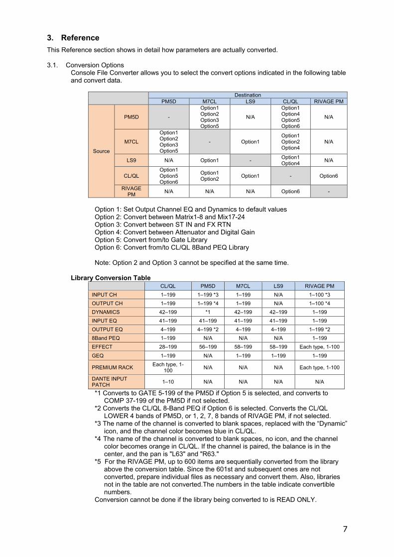
This Reference section shows in detail how parameters are actually converted. 3.1. Conversion Options
Console File Converter allows you to select the convert options indicated in the following table and convert data.
Destination PM5D M7CL LS9 CL/QL RIVAGE PM
Source
PM5D -
Option1 Option2 Option3 Option5
N/A
Option1 Option4 Option5 Option6
N/A
M7CL
Option1 Option2 Option3 Option5
- Option1 Option1 Option2 Option4
N/A
LS9 N/A Option1 - Option1 Option4 N/A
CL/QL Option1 Option5 Option6
Option1 Option2 Option1 - Option6
RIVAGE PM N/A N/A N/A Option6 -
Option 1: Set Output Channel EQ and Dynamics to default values Option 2: Convert between Matrix1-8 and Mix17-24 Option 3: Convert between ST IN and FX RTN Option 4: Convert between Attenuator and Digital Gain Option 5: Convert from/to Gate Library Option 6: Convert from/to CL/QL 8Band PEQ Library
Note: Option 2 and Option 3 cannot be specified at the same time.
Library Conversion Table CL/QL PM5D M7CL LS9 RIVAGE PM INPUT CH 1–199 1–199 *3 1–199 N/A 1–100 *3 OUTPUT CH 1–199 1–199 *4 1–199 N/A 1–100 *4 DYNAMICS 42–199 *1 42–199 42–199 1–199 INPUT EQ 41–199 41–199 41–199 41–199 1–199 OUTPUT EQ 4–199 4–199 *2 4–199 4–199 1–199 *2 8Band PEQ 1–199 N/A N/A N/A 1–199 EFFECT 28–199 56–199 58–199 58–199 Each type, 1-100 GEQ 1–199 N/A 1–199 1–199 1–199
PREMIUM RACK Each type, 1-100 N/A N/A N/A Each type, 1-100
DANTE INPUT PATCH 1–10 N/A N/A N/A N/A
*1 Converts to GATE 5-199 of the PM5D if Option 5 is selected, and converts to COMP 37-199 of the PM5D if not selected.
*2 Converts the CL/QL 8-Band PEQ if Option 6 is selected. Converts the CL/QL LOWER 4 bands of PM5D, or 1, 2, 7, 8 bands of RIVAGE PM, if not selected.
*3 The name of the channel is converted to blank spaces, replaced with the “Dynamic” icon, and the channel color becomes blue in CL/QL.
*4 The name of the channel is converted to blank spaces, no icon, and the channel color becomes orange in CL/QL. If the channel is paired, the balance is in the center, and the pan is "L63" and "R63."
*5 For the RIVAGE PM, up to 600 items are sequentially converted from the library above the conversion table. Since the 601st and subsequent ones are not converted, prepare individual files as necessary and convert them. Also, libraries not in the table are not converted.The numbers in the table indicate convertible numbers.
Conversion cannot be done if the library being converted to is READ ONLY.
8
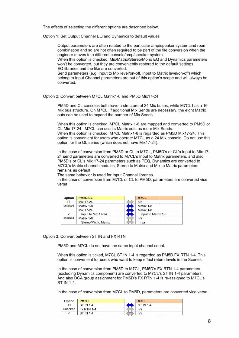
The effects of selecting the different options are described below. Option 1: Set Output Channel EQ and Dynamics to default values
Output parameters are often related to the particular amp/speaker system and room combination and so are not often required to be part of the file conversion when the engineer moves to a different console/amp/speaker system. When this option is checked, Mix/Matrix/Stereo/Mono EQ and Dynamics parameters won’t be converted, but they are conveniently restored to the default settings. EQ libraries and the like are converted. Send parameters (e.g. Input to Mix level/on-off, Input to Matrix level/on-off) which belong to Input Channel parameters are out of this option’s scope and will always be converted.
Option 2: Convert between M7CL Matrix1-8 and PM5D Mix17-24
PM5D and CL consoles both have a structure of 24 Mix buses, while M7CL has a 16 Mix bus structure. On M7CL, if additional Mix Sends are necessary, the eight Matrix outs can be used to expand the number of Mix Sends. When this option is checked, M7CL Matrix 1-8 are mapped and converted to PM5D or CL Mix 17-24. M7CL can use its Matrix outs as more Mix Sends. When this option is checked, M7CL Matrix1-8 is regarded as PM5D Mix17-24. This option is convenient for users who operate M7CL as a 24 Mix console. Do not use this option for the QL series (which does not have Mix17-24). In the case of conversion from PM5D or CL to M7CL, PM5D’s or CL’s Input to Mix 17-24 send parameters are converted to M7CL’s Input to Matrix parameters, and also PM5D’s or CL’s Mix 17-24 parameters such as PEQ, Dynamics are converted to M7CL’s Matrix channel modules. Stereo to Matrix and Mix to Matrix parameters remains as default. The same behavior is used for Input Channel libraries. In the case of conversion from M7CL or CL to PM5D, parameters are converted vice versa.
Option PM5D/CL M7CL Mix 17-24 n/a
unticked Matrix 1-8 Matrix 1-8 Mix 17-24 Matrix 1-8 Input to Mix 17-24 Input to Matrix 1-8
checked Matrix 1-8 n/a Stereo/Mix to Matrix n/a
Option 3: Convert between ST IN and FX RTN PM5D and M7CL do not have the same input channel count. When this option is ticked, M7CL ST IN 1-4 is regarded as PM5D FX RTN 1-4. This option is convenient for users who want to keep effect return levels in the Scenes. In the case of conversion from PM5D to M7CL, PM5D’s FX RTN 1-4 parameters (excluding Dynamics component) are converted to M7CL’s ST IN 1-4 parameters. And also DCA group assignment for PM5D’s FX RTN 1-4 is re-assigned to M7CL’s ST IN 1-4. In the case of conversion from M7CL to PM5D, parameters are converted vice versa.
Option PM5D M7CL ST IN 1-4 ST IN 1-4
unticked Fx RTN 1-4 n/a ST IN 1-4 n/a
9
checked Fx RTN 1-4 ST IN 1-4
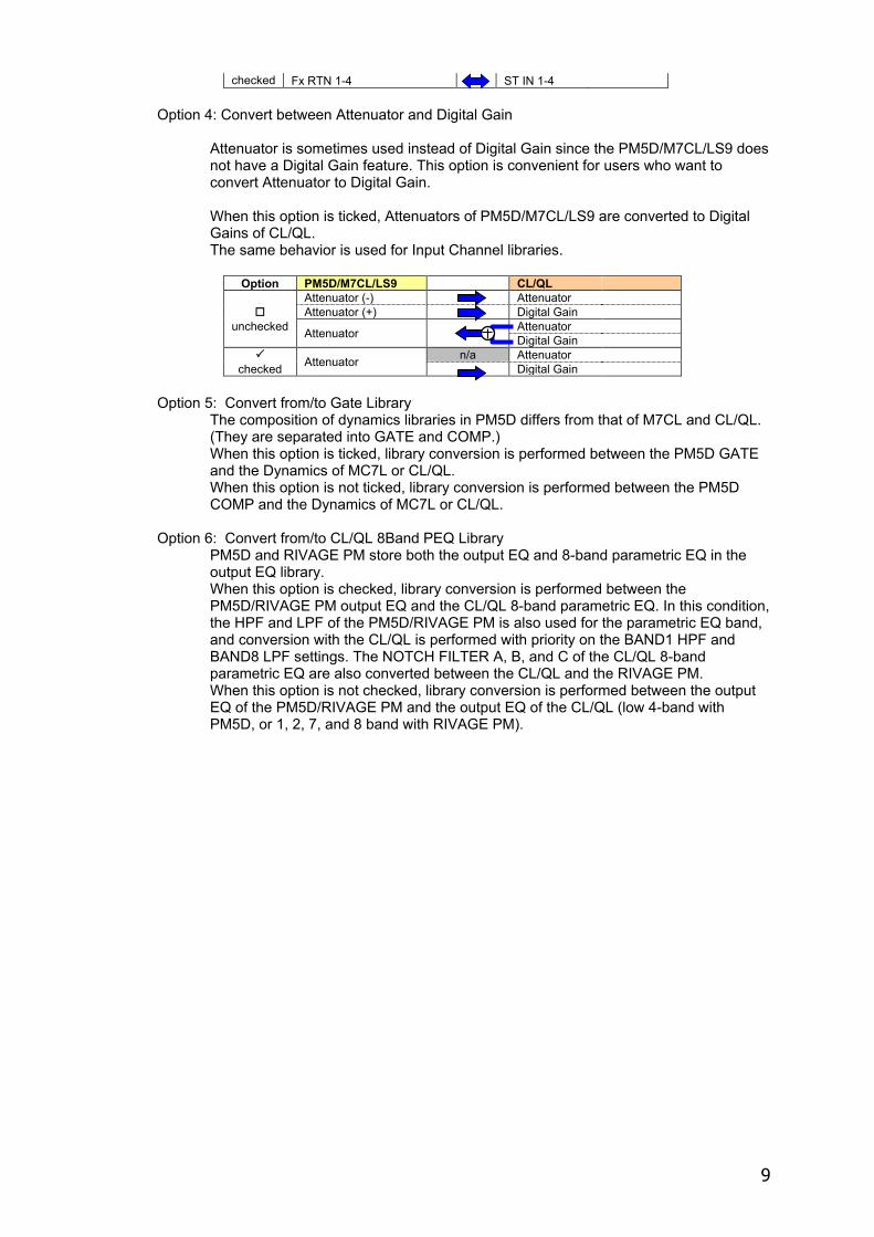
Option 4: Convert between Attenuator and Digital Gain Attenuator is sometimes used instead of Digital Gain since the PM5D/M7CL/LS9 does not have a Digital Gain feature. This option is convenient for users who want to convert Attenuator to Digital Gain. When this option is ticked, Attenuators of PM5D/M7CL/LS9 are converted to Digital Gains of CL/QL. The same behavior is used for Input Channel libraries.
Option PM5D/M7CL/LS9 CL/QL Attenuator (-) Attenuator Attenuator (+) Digital Gain
unchecked Attenuator Attenuator Digital Gain Attenuator n/a Attenuator
checked Digital Gain
Option 5: Convert from/to Gate Library The composition of dynamics libraries in PM5D differs from that of M7CL and CL/QL. (They are separated into GATE and COMP.) When this option is ticked, library conversion is performed between the PM5D GATE and the Dynamics of MC7L or CL/QL. When this option is not ticked, library conversion is performed between the PM5D COMP and the Dynamics of MC7L or CL/QL.
Option 6: Convert from/to CL/QL 8Band PEQ Library
PM5D and RIVAGE PM store both the output EQ and 8-band parametric EQ in the output EQ library. When this option is checked, library conversion is performed between the PM5D/RIVAGE PM output EQ and the CL/QL 8-band parametric EQ. In this condition, the HPF and LPF of the PM5D/RIVAGE PM is also used for the parametric EQ band, and conversion with the CL/QL is performed with priority on the BAND1 HPF and BAND8 LPF settings. The NOTCH FILTER A, B, and C of the CL/QL 8-band parametric EQ are also converted between the CL/QL and the RIVAGE PM. When this option is not checked, library conversion is performed between the output EQ of the PM5D/RIVAGE PM and the output EQ of the CL/QL (low 4-band with PM5D, or 1, 2, 7, and 8 band with RIVAGE PM).
10
The following describes the scene conversion between models in detail.
3.2. Conversion between PM5D and M7CL
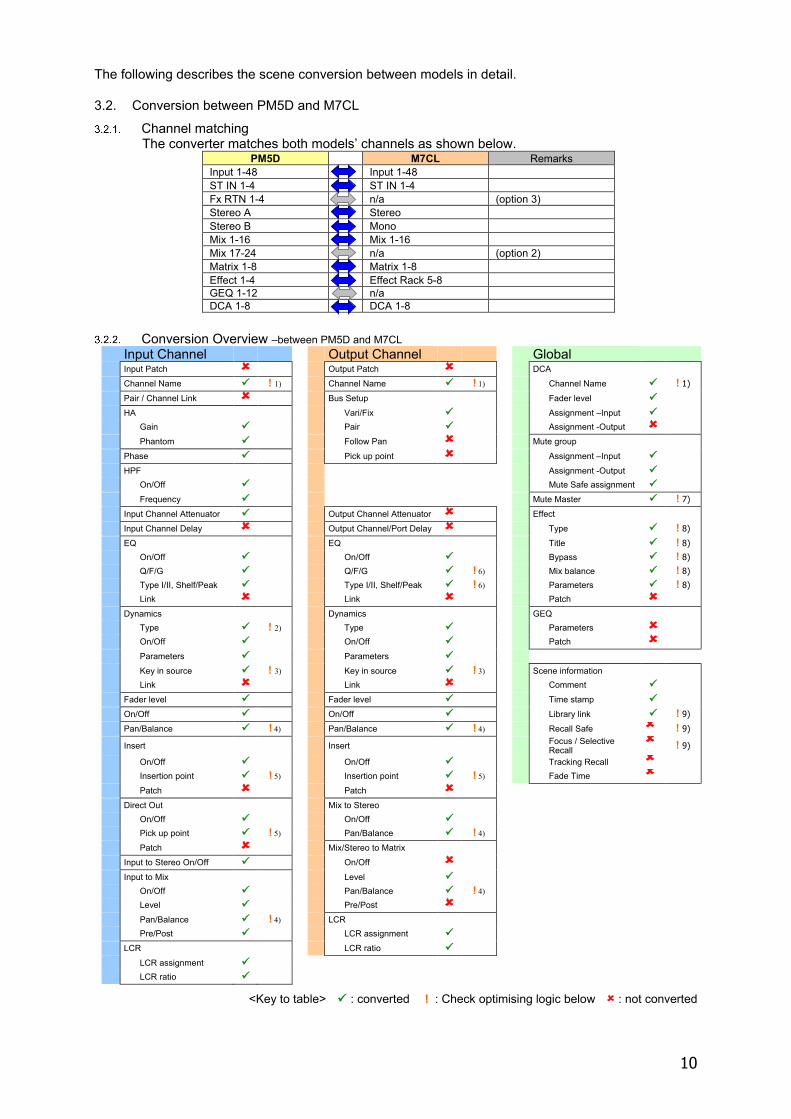
Channel matching The converter matches both models’ channels as shown below.
PM5D M7CL Remarks Input 1-48 Input 1-48 ST IN 1-4 ST IN 1-4 Fx RTN 1-4 n/a (option 3) Stereo A Stereo Stereo B Mono Mix 1-16 Mix 1-16 Mix 17-24 n/a (option 2) Matrix 1-8 Matrix 1-8 Effect 1-4 Effect Rack 5-8 GEQ 1-12 n/a DCA 1-8 DCA 1-8
Conversion Overview –between PM5D and M7CL
Input Channel Output Channel Global Input Patch Output Patch DCA Channel Name ! 1) Channel Name ! 1) Channel Name ! 1)
Pair / Channel Link Bus Setup Fader level
HA Vari/Fix Assignment –Input
Gain Pair Assignment -Output
Phantom Follow Pan Mute group
Phase Pick up point Assignment –Input
HPF Assignment -Output
On/Off Mute Safe assignment
Frequency Mute Master ! 7)
Input Channel Attenuator Output Channel Attenuator Effect
Input Channel Delay Output Channel/Port Delay Type ! 8)
EQ EQ Title ! 8)
On/Off On/Off Bypass ! 8)
Q/F/G Q/F/G ! 6) Mix balance ! 8)
Type I/II, Shelf/Peak Type I/II, Shelf/Peak ! 6) Parameters ! 8)
Link Link Patch
Dynamics Dynamics GEQ
Type ! 2) Type Parameters
On/Off On/Off Patch
Parameters Parameters
Key in source ! 3) Key in source ! 3) Scene information
Link Link Comment
Fader level Fader level Time stamp
On/Off On/Off Library link ! 9)
Pan/Balance ! 4) Pan/Balance ! 4) Recall Safe ! 9)
Insert Insert Focus / Selective Recall
! 9)
On/Off On/Off Tracking Recall
Insertion point ! 5) Insertion point ! 5) Fade Time
Patch Patch
Direct Out Mix to Stereo
On/Off On/Off
Pick up point ! 5) Pan/Balance ! 4)
Patch Mix/Stereo to Matrix
Input to Stereo On/Off On/Off
Input to Mix Level
On/Off Pan/Balance ! 4)
Level Pre/Post
Pan/Balance ! 4) LCR
Pre/Post LCR assignment
LCR LCR ratio
LCR assignment
LCR ratio
<Key to table> : converted ! : Check optimising logic below : not converted
11
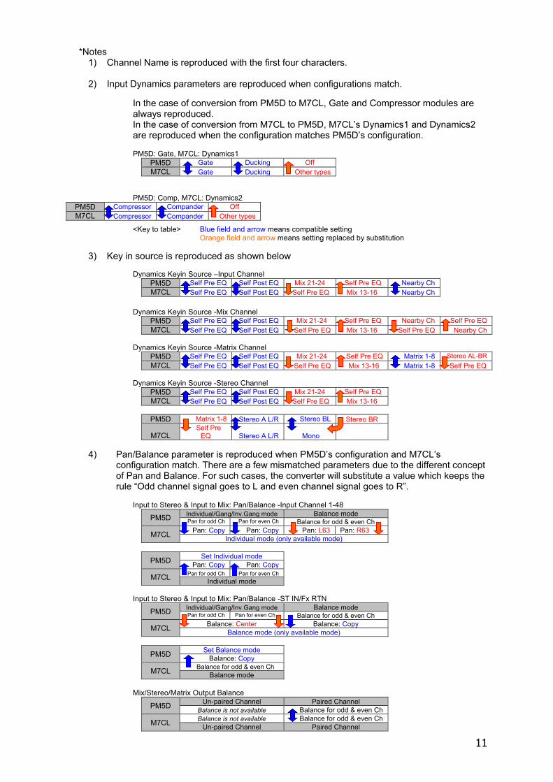
*Notes 1) Channel Name is reproduced with the first four characters.
2) Input Dynamics parameters are reproduced when configurations match.
In the case of conversion from PM5D to M7CL, Gate and Compressor modules are always reproduced. In the case of conversion from M7CL to PM5D, M7CL’s Dynamics1 and Dynamics2 are reproduced when the configuration matches PM5D’s configuration. PM5D: Gate, M7CL: Dynamics1
PM5D Gate Ducking Off M7CL Gate Ducking Other types
PM5D: Comp, M7CL: Dynamics2
<Key to table> Blue field and arrow means compatible setting Orange field and arrow means setting replaced by substitution
3) Key in source is reproduced as shown below
Dynamics Keyin Source –Input Channel
PM5D Self Pre EQ Self Post EQ Mix 21-24 Self Pre EQ Nearby Ch M7CL Self Pre EQ Self Post EQ Self Pre EQ Mix 13-16 Nearby Ch
Dynamics Keyin Source -Mix Channel
PM5D Self Pre EQ Self Post EQ Mix 21-24 Self Pre EQ Nearby Ch Self Pre EQ M7CL Self Pre EQ Self Post EQ Self Pre EQ Mix 13-16 Self Pre EQ Nearby Ch
Dynamics Keyin Source -Matrix Channel
PM5D Self Pre EQ Self Post EQ Mix 21-24 Self Pre EQ Matrix 1-8 Stereo AL-BR M7CL Self Pre EQ Self Post EQ Self Pre EQ Mix 13-16 Matrix 1-8 Self Pre EQ
Dynamics Keyin Source -Stereo Channel
PM5D Self Pre EQ Self Post EQ Mix 21-24 Self Pre EQ M7CL Self Pre EQ Self Post EQ Self Pre EQ Mix 13-16
PM5D Matrix 1-8 Stereo A L/R Stereo BL Stereo BR
M7CL Self Pre
EQ Stereo A L/R Mono
4) Pan/Balance parameter is reproduced when PM5D’s configuration and M7CL’s configuration match. There are a few mismatched parameters due to the different concept of Pan and Balance. For such cases, the converter will substitute a value which keeps the rule “Odd channel signal goes to L and even channel signal goes to R”.
Input to Stereo & Input to Mix: Pan/Balance -Input Channel 1-48
PM5D Individual/Gang/Inv.Gang mode Balance mode Pan for odd Ch Pan for even Ch Balance for odd & even Ch
M7CL Pan: Copy Pan: Copy Pan: L63 Pan: R63 Individual mode (only available mode)
PM5D Set Individual mode Pan: Copy Pan: Copy
M7CL Pan for odd Ch Pan for even Ch Individual mode
Input to Stereo & Input to Mix: Pan/Balance -ST IN/Fx RTN
PM5D Individual/Gang/Inv.Gang mode Balance mode Pan for odd Ch Pan for even Ch Balance for odd & even Ch
M7CL Balance: Center Balance: Copy Balance mode (only available mode)
PM5D Set Balance mode Balance: Copy
M7CL Balance for odd & even Ch Balance mode
Mix/Stereo/Matrix Output Balance
PM5D Un-paired Channel Paired Channel Balance is not available Balance for odd & even Ch
M7CL Balance is not available Balance for odd & even Ch Un-paired Channel Paired Channel
PM5D Compressor Compander Off M7CL Compressor Compander Other types
12
Mix to Stereo, Mix to Matrix & Stereo to Matrix: Pan/Balance
PM5D Un-paired Channel Paired Channel * Odd Ch value Even Ch value Odd Ch value Even Ch value
M7CL Pan: Copy Pan: Copy Pan: L63 Pan: R63 Balance: Center
PM5D Pan: Copy Pan: Copy Pan: L63 Pan: R63
M7CL Odd Ch value Even Ch value
Pan: L63 Pan: R63 Balance for odd & even Ch
Un-paired Channel Paired Channel * Mix to Stereo, Mix to Matrix and Stereo to Matrix on PM5D’s paired channels doesn’t have Balance.
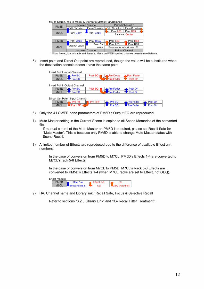
5) Insert point and Direct Out point are reproduced, though the value will be substituted when the destination console doesn’t have the same point.
Insert Point -Input Channel
PM5D Pre EQ Post EQ Pre Delay Post Fader M7CL Pre EQ Pre Fader Post On
Insert Point -Output Channel
PM5D Pre EQ Post EQ Pre Fader Post On M7CL Pre EQ Pre Fader Post On
Direct Out Point -Input Channel
PM5D Pre Att Pre HPF Pre EQ Pre Fader Post On M7CL Pre HPF Pre EQ Pre Fader Post On
6) Only the 4 LOWER band parameters of PM5D’s Output EQ are reproduced.
7) Mute Master setting in the Current Scene is copied to all Scene Memories of the converted
file. If manual control of the Mute Master on PM5D is required, please set Recall Safe for “Mute Master”. This is because only PM5D is able to change Mute Master status with Scene Recall.
8) A limited number of Effects are reproduced due to the difference of available Effect unit
numbers. In the case of conversion from PM5D to M7CL, PM5D’s Effects 1-4 are converted to M7CL’s rack 5-8 Effects. In the case of conversion from M7CL to PM5D, M7CL’s Rack 5-8 Effects are converted to PM5D’s Effects 1-4 (when M7CL racks are set to Effect, not GEQ). Effect module
PM5D Effect 1-4 Effect 5-8 n/a M7CL Effect(Rack5-8) n/a GEQ (Rack5-8)
9) HA, Channel name and Library link / Recall Safe, Focus & Selective Recall
Refer to sections “3.2.3 Library Link” and “3.4 Recall Filter Treatment”.
13
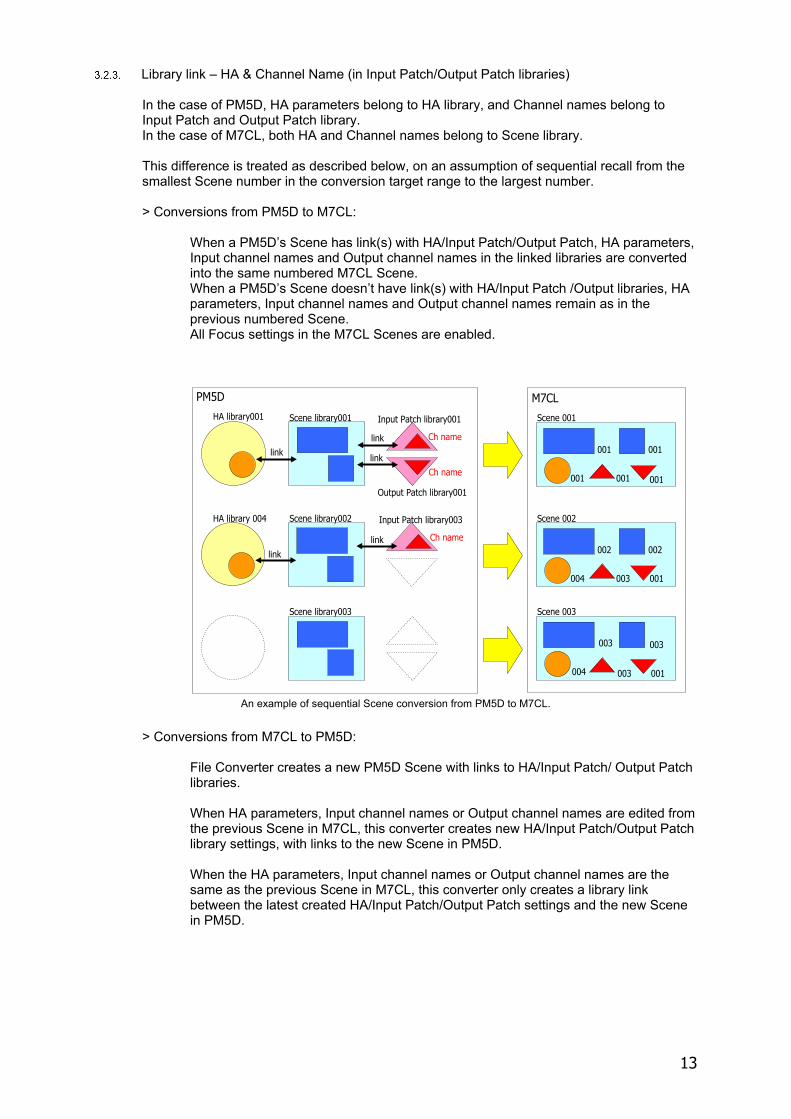
Library link – HA & Channel Name (in Input Patch/Output Patch libraries) In the case of PM5D, HA parameters belong to HA library, and Channel names belong to Input Patch and Output Patch library. In the case of M7CL, both HA and Channel names belong to Scene library.
This difference is treated as described below, on an assumption of sequential recall from the smallest Scene number in the conversion target range to the largest number.
> Conversions from PM5D to M7CL:
When a PM5D’s Scene has link(s) with HA/Input Patch/Output Patch, HA parameters, Input channel names and Output channel names in the linked libraries are converted into the same numbered M7CL Scene. When a PM5D’s Scene doesn’t have link(s) with HA/Input Patch /Output libraries, HA parameters, Input channel names and Output channel names remain as in the previous numbered Scene. All Focus settings in the M7CL Scenes are enabled.
An example of sequential Scene conversion from PM5D to M7CL.
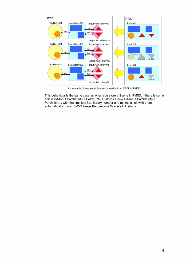
> Conversions from M7CL to PM5D:
File Converter creates a new PM5D Scene with links to HA/Input Patch/ Output Patch libraries.
When HA parameters, Input channel names or Output channel names are edited from the previous Scene in M7CL, this converter creates new HA/Input Patch/Output Patch library settings, with links to the new Scene in PM5D.
When the HA parameters, Input channel names or Output channel names are the same as the previous Scene in M7CL, this converter only creates a library link between the latest created HA/Input Patch/Output Patch settings and the new Scene in PM5D.
HA library001 Scene library001 Input Patch library001
Output Patch library001
linklink
link
Scene 001
001 001
001 001 001
HA library 004 Scene library002 Input Patch library003
linklink
Scene 002
002 002
004 003 001
PM5D M7CL
Scene library003 Scene 003
003 003
004 003 001
Ch name
Ch name
Ch name
14
An example of sequential Scene conversion from M7CL to PM5D.
This behaviour is the same case as when you store a Scene in PM5D: if there is some edit in HA/Input Patch/Output Patch, PM5D stores a new HA/Input Patch/Output Patch library with the smallest free library number and makes a link with them automatically. If not, PM5D keeps the previous Scene’s link status.
HA library001 Scene library001 Input Patch library001
Output Patch library001
linklink
link
Scene 001
PM5D M7CL
HA library001 Scene library002 Input Patch library001
Output Patch library001
Scene 002
HA library002 Scene library003 Input Patch library002
Output Patch library001
link
Scene 003
link
No edit
No edit
No edit
No editlink
link
linklink
15
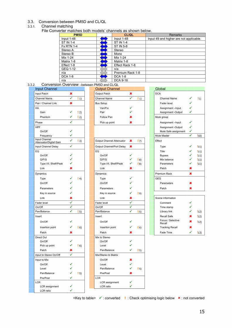
3.3. Conversion between PM5D and CL/QL Channel matching
File Converter matches both models’ channels as shown below. PM5D CL/QL Remarks
Input 1-48 Input 1-48 Input 49 and higher are not applicable. ST IN 1-4 ST IN 1-4 Fx RTN 1-4 ST IN 5-8 Stereo A Stereo Stereo B Mono Mix 1-24 Mix 1-24 Matrix 1-8 Matrix 1-8 Effect 1-8 Effect Rack 1-8 GEQ 1-12 n/a n/a Premium Rack 1-8 DCA 1-8 DCA 1-8 n/a DCA 9-16
Conversion Overview –between PM5D and CL/QL Input Channel Output Channel Global
Input Patch Output Patch DCA Channel Name ! 1) Channel Name ! 1) Channel Name !1)
Pair / Channel Link Bus Setup Fader level
HA Vari/Fix Assignment –Input
Gain ! 2) Pair Assignment -Output
Phantom ! 2) Follow Pan Mute group
Phase Pick up point Assignment –Input
HPF Assignment -Output
On/Off Mute Safe assignment
Frequency Mute Master !10)
Input Channel Attenuator/Digital Gain ! 3) Output Channel Attenuator ! 7) Effect
Input Channel Delay Output Channel/Port Delay Type !11)
EQ EQ Title !11) On/Off On/Off Bypass !11) Q/F/G Q/F/G ! 8) Mix balance !11) Type I/II, Shelf/Peak Type I/II, Shelf/Peak ! 8) Parameters !11)
Link Link Patch
Dynamics Dynamics Premium Rack
Type ! 4) Type GEQ
On/Off On/Off Parameters
Parameters Parameters Patch
Key in source Key in source ! 9)
Link Link Scene information
Fader level Fader level Comment
On/Off On/Off Time stamp
Pan/Balance ! 5) Pan/Balance ! 5) Library link !12)
Insert Insert Recall Safe !12)
On/Off On/Off Focus / Selective Recall !12)
Insertion point ! 6) Insertion point ! 6) Tracking Recall
Patch Patch Fade Time !13)
Direct Out Mix to Stereo On/Off On/Off Pick up point ! 6) Level
Patch Pan/Balance ! 5) Input to Stereo On/Off Mix/Stereo to Matrix
Input to Mix On/Off On/Off Level Level Pan/Balance ! 5)
Pan/Balance ! 5) Pre/Post Pre/Post LCR LCR LCR assignment LCR assignment LCR ratio LCR ratio
<Key to table> : converted ! : Check optimising logic below : not converted
16
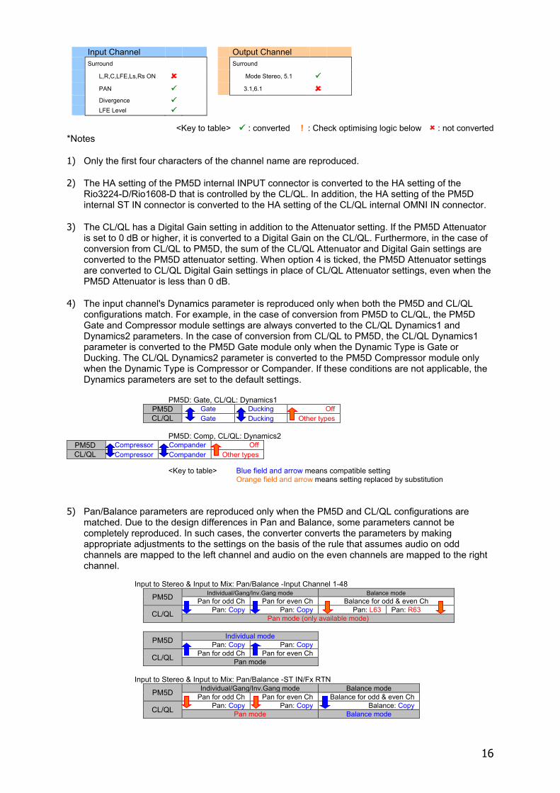
Input Channel Output Channel
Surround Surround
L,R,C,LFE,Ls,Rs ON Mode Stereo, 5.1
PAN 3.1,6.1 Divergence LFE Level
<Key to table> : converted ! : Check optimising logic below : not converted
*Notes 1) Only the first four characters of the channel name are reproduced. 2) The HA setting of the PM5D internal INPUT connector is converted to the HA setting of the
Rio3224-D/Rio1608-D that is controlled by the CL/QL. In addition, the HA setting of the PM5D internal ST IN connector is converted to the HA setting of the CL/QL internal OMNI IN connector.
3) The CL/QL has a Digital Gain setting in addition to the Attenuator setting. If the PM5D Attenuator
is set to 0 dB or higher, it is converted to a Digital Gain on the CL/QL. Furthermore, in the case of conversion from CL/QL to PM5D, the sum of the CL/QL Attenuator and Digital Gain settings are converted to the PM5D attenuator setting. When option 4 is ticked, the PM5D Attenuator settings are converted to CL/QL Digital Gain settings in place of CL/QL Attenuator settings, even when the PM5D Attenuator is less than 0 dB.
4) The input channel's Dynamics parameter is reproduced only when both the PM5D and CL/QL
configurations match. For example, in the case of conversion from PM5D to CL/QL, the PM5D Gate and Compressor module settings are always converted to the CL/QL Dynamics1 and Dynamics2 parameters. In the case of conversion from CL/QL to PM5D, the CL/QL Dynamics1 parameter is converted to the PM5D Gate module only when the Dynamic Type is Gate or Ducking. The CL/QL Dynamics2 parameter is converted to the PM5D Compressor module only when the Dynamic Type is Compressor or Compander. If these conditions are not applicable, the Dynamics parameters are set to the default settings.
PM5D: Gate, CL/QL: Dynamics1
PM5D Gate Ducking Off CL/QL Gate Ducking Other types
PM5D: Comp, CL/QL: Dynamics2
<Key to table> Blue field and arrow means compatible setting Orange field and arrow means setting replaced by substitution
5) Pan/Balance parameters are reproduced only when the PM5D and CL/QL configurations are matched. Due to the design differences in Pan and Balance, some parameters cannot be completely reproduced. In such cases, the converter converts the parameters by making appropriate adjustments to the settings on the basis of the rule that assumes audio on odd channels are mapped to the left channel and audio on the even channels are mapped to the right channel.
Input to Stereo & Input to Mix: Pan/Balance -Input Channel 1-48
PM5D Individual/Gang/Inv.Gang mode Balance mode Pan for odd Ch Pan for even Ch Balance for odd & even Ch
CL/QL Pan: Copy Pan: Copy Pan: L63 Pan: R63 Pan mode (only available mode)
PM5D Individual mode Pan: Copy Pan: Copy
CL/QL Pan for odd Ch Pan for even Ch Pan mode
Input to Stereo & Input to Mix: Pan/Balance -ST IN/Fx RTN
PM5D Individual/Gang/Inv.Gang mode Balance mode Pan for odd Ch Pan for even Ch Balance for odd & even Ch
CL/QL Pan: Copy Pan: Copy Balance: Copy Pan mode Balance mode
PM5D Compressor Compander Off CL/QL Compressor Compander Other types
17
PM5D Individual mode Balance mode Pan: Copy Pan: Copy Balance: Copy
CL/QL Pan for odd Ch Pan for even Ch Balance for odd & even
Ch Pan mode Balance mode
Mix/Stereo/Matrix Output Balance
PM5D Un-paired Channel Paired Channel Balance is not available Balance for odd & even Ch
CL/QL Balance is not available Balance for odd & even Ch Un-paired Channel Paired Channel
Mix to Stereo, Mix to Matrix & Stereo to Matrix: Pan/Balance
PM5D Un-paired Channel Paired Channel * Odd Ch value Even Ch value Odd Ch value Even Ch value
CL/QL Pan: Copy Pan: Copy Pan: L63 Pan: R63 Balance: Center
PM5D Pan: Copy Pan: Copy Pan: L63 Pan: R63
CL/QL Odd Ch value Even Ch value Pan: L63 Pan: R63 Balance for odd & even Ch
Un-paired Channel Paired Channel * Mix to Stereo, Mix to Matrix and Stereo to Matrix on PM5D’s paired channels don’t have Balance.
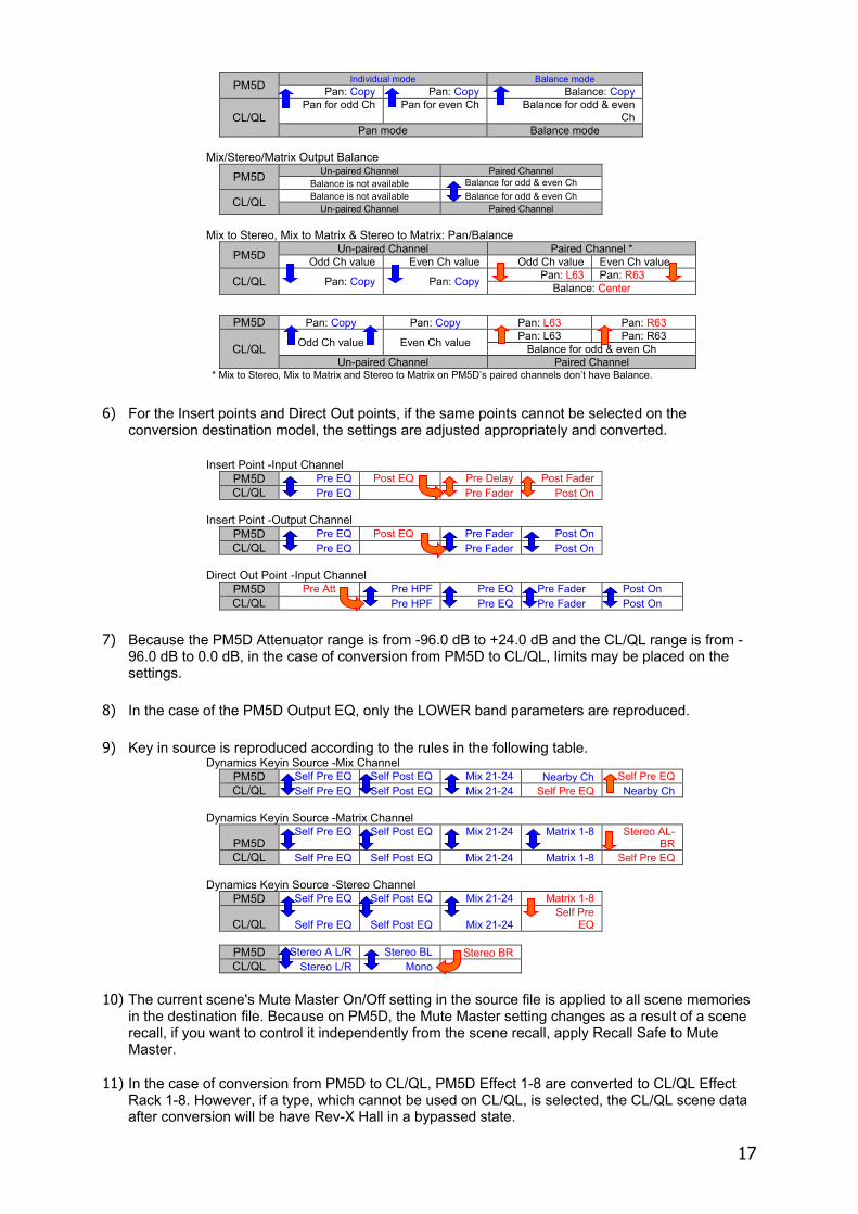
6) For the Insert points and Direct Out points, if the same points cannot be selected on the conversion destination model, the settings are adjusted appropriately and converted.
Insert Point -Input Channel
PM5D Pre EQ Post EQ Pre Delay Post Fader CL/QL Pre EQ Pre Fader Post On
Insert Point -Output Channel
PM5D Pre EQ Post EQ Pre Fader Post On CL/QL Pre EQ Pre Fader Post On
Direct Out Point -Input Channel
PM5D Pre Att Pre HPF Pre EQ Pre Fader Post On CL/QL Pre HPF Pre EQ Pre Fader Post On
7) Because the PM5D Attenuator range is from -96.0 dB to +24.0 dB and the CL/QL range is from -
96.0 dB to 0.0 dB, in the case of conversion from PM5D to CL/QL, limits may be placed on the settings.
8) In the case of the PM5D Output EQ, only the LOWER band parameters are reproduced. 9) Key in source is reproduced according to the rules in the following table.
Dynamics Keyin Source -Mix Channel PM5D Self Pre EQ Self Post EQ Mix 21-24 Nearby Ch Self Pre EQ CL/QL Self Pre EQ Self Post EQ Mix 21-24 Self Pre EQ Nearby Ch
Dynamics Keyin Source -Matrix Channel
PM5D Self Pre EQ Self Post EQ Mix 21-24 Matrix 1-8 Stereo AL-
BR CL/QL Self Pre EQ Self Post EQ Mix 21-24 Matrix 1-8 Self Pre EQ
Dynamics Keyin Source -Stereo Channel
PM5D Self Pre EQ Self Post EQ Mix 21-24 Matrix 1-8
CL/QL Self Pre EQ Self Post EQ Mix 21-24 Self Pre
EQ
PM5D Stereo A L/R Stereo BL Stereo BR CL/QL Stereo L/R Mono
10) The current scene's Mute Master On/Off setting in the source file is applied to all scene memories
in the destination file. Because on PM5D, the Mute Master setting changes as a result of a scene recall, if you want to control it independently from the scene recall, apply Recall Safe to Mute Master.
11) In the case of conversion from PM5D to CL/QL, PM5D Effect 1-8 are converted to CL/QL Effect
Rack 1-8. However, if a type, which cannot be used on CL/QL, is selected, the CL/QL scene data after conversion will be have Rev-X Hall in a bypassed state.
18
On the other hand, in the case of conversion from CL/QL to PM5D, only those in CL/QL Effect Rack 1-8 that are being used as Effect units are converted to PM5D Effect 1-8. If a CL/QL Effect Rack is being used as GEQ, this is not converted to the PM5D scene.
12) For details about the reproducibility of Library link Recall, Recall Safe, and Focus & Selective
Recall, refer to section "3.2.3 Library link – HA & Channel Name (in Input Patch/Output Patch libraries)" or "3.8 “Recall Filter” Treatment".
13) In the case of conversion from PM5D to CL/QL, the Individual mode is always On. In the case of
conversion from CL/QL to PM5, Pan will not be converted.
19
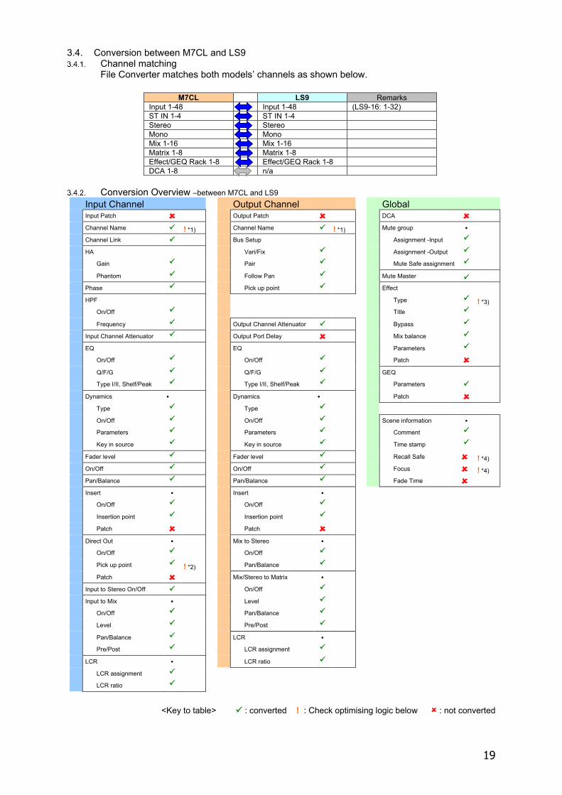
3.4. Conversion between M7CL and LS9 Channel matching
File Converter matches both models’ channels as shown below.
M7CL LS9 Remarks Input 1-48 Input 1-48 (LS9-16: 1-32) ST IN 1-4 ST IN 1-4 Stereo Stereo Mono Mono Mix 1-16 Mix 1-16 Matrix 1-8 Matrix 1-8 Effect/GEQ Rack 1-8 Effect/GEQ Rack 1-8 DCA 1-8 n/a
Conversion Overview –between M7CL and LS9
Input Channel Output Channel Global Input Patch Output Patch DCA Channel Name ! *1) Channel Name ! *1) Mute group Channel Link Bus Setup Assignment -Input HA Vari/Fix Assignment -Output Gain Pair Mute Safe assignment Phantom Follow Pan Mute Master Phase Pick up point Effect HPF Type ! *3) On/Off Title Frequency Output Channel Attenuator Bypass Input Channel Attenuator Output Port Delay Mix balance EQ EQ Parameters On/Off On/Off Patch Q/F/G Q/F/G GEQ Type I/II, Shelf/Peak Type I/II, Shelf/Peak Parameters Dynamics Dynamics Patch Type Type On/Off On/Off Scene information Parameters Parameters Comment Key in source Key in source Time stamp Fader level Fader level Recall Safe ! *4) On/Off On/Off Focus ! *4) Pan/Balance Pan/Balance Fade Time Insert Insert On/Off On/Off Insertion point Insertion point Patch Patch Direct Out Mix to Stereo On/Off On/Off Pick up point ! *2) Pan/Balance Patch Mix/Stereo to Matrix Input to Stereo On/Off On/Off Input to Mix Level On/Off Pan/Balance Level Pre/Post Pan/Balance LCR Pre/Post LCR assignment LCR LCR ratio LCR assignment LCR ratio
<Key to table> : converted ! : Check optimising logic below : not converted
20
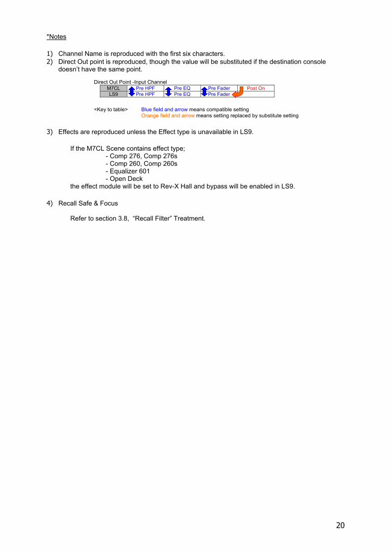
*Notes 1) Channel Name is reproduced with the first six characters. 2) Direct Out point is reproduced, though the value will be substituted if the destination console
doesn’t have the same point. Direct Out Point -Input Channel
M7CL Pre HPF Pre EQ Pre Fader Post On LS9 Pre HPF Pre EQ Pre Fader
<Key to table> Blue field and arrow means compatible setting
Orange field and arrow means setting replaced by substitute setting 3) Effects are reproduced unless the Effect type is unavailable in LS9.
If the M7CL Scene contains effect type;
- Comp 276, Comp 276s - Comp 260, Comp 260s - Equalizer 601 - Open Deck
the effect module will be set to Rev-X Hall and bypass will be enabled in LS9. 4) Recall Safe & Focus
Refer to section 3.8, “Recall Filter” Treatment.
21
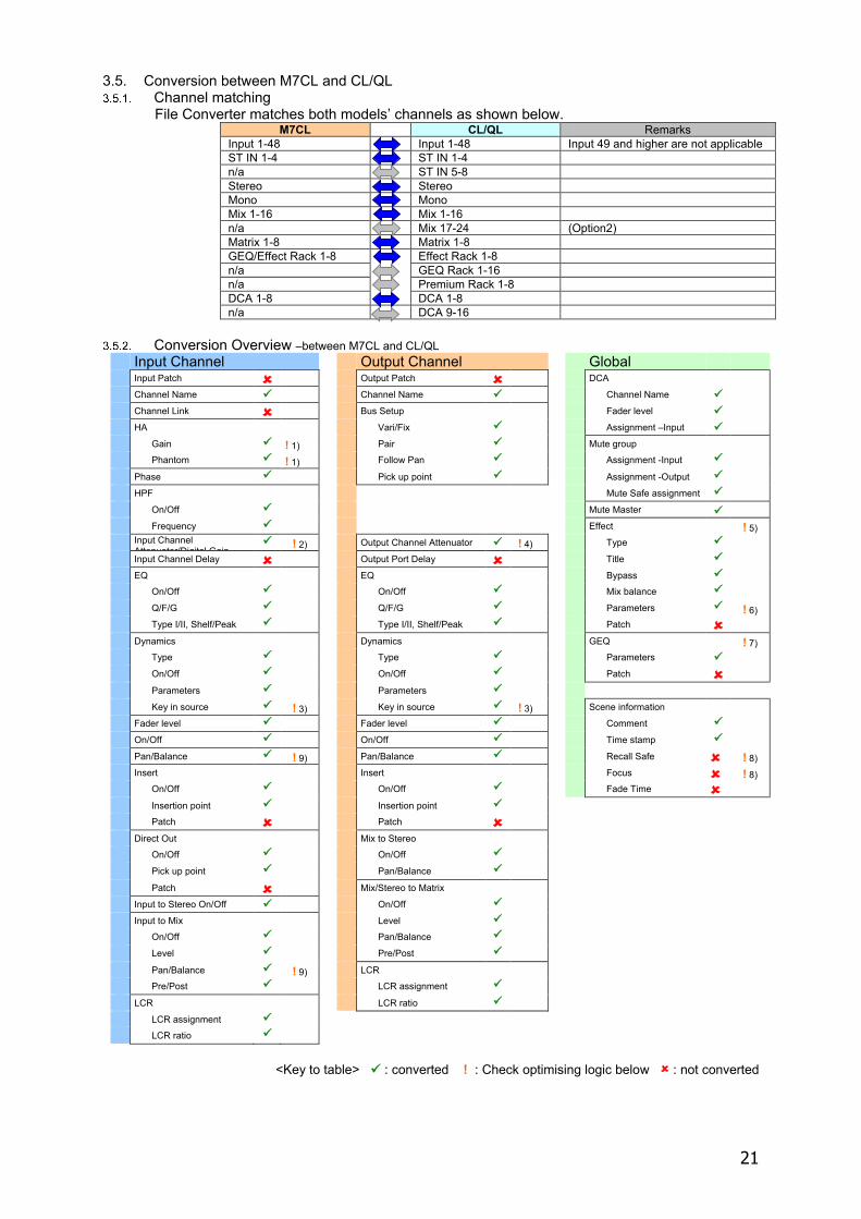
3.5. Conversion between M7CL and CL/QL Channel matching
File Converter matches both models’ channels as shown below. M7CL CL/QL Remarks
Input 1-48 Input 1-48 Input 49 and higher are not applicable ST IN 1-4 ST IN 1-4 n/a ST IN 5-8 Stereo Stereo Mono Mono Mix 1-16 Mix 1-16 n/a Mix 17-24 (Option2) Matrix 1-8 Matrix 1-8 GEQ/Effect Rack 1-8 Effect Rack 1-8 n/a GEQ Rack 1-16 n/a Premium Rack 1-8 DCA 1-8 DCA 1-8 n/a DCA 9-16
Conversion Overview –between M7CL and CL/QL
Input Channel Output Channel Global Input Patch Output Patch DCA Channel Name Channel Name Channel Name Channel Link Bus Setup Fader level HA Vari/Fix Assignment –Input Gain ! 1) Pair Mute group Phantom ! 1) Follow Pan Assignment -Input Phase Pick up point Assignment -Output HPF Mute Safe assignment On/Off Mute Master Frequency Effect ! 5) Input Channel
Attenuator/Digital Gain ! 2) Output Channel Attenuator ! 4) Type
Input Channel Delay Output Port Delay Title EQ EQ Bypass On/Off On/Off Mix balance Q/F/G Q/F/G Parameters ! 6) Type I/II, Shelf/Peak Type I/II, Shelf/Peak Patch Dynamics Dynamics GEQ ! 7) Type Type Parameters On/Off On/Off Patch Parameters Parameters Key in source ! 3) Key in source ! 3) Scene information Fader level Fader level Comment On/Off On/Off Time stamp Pan/Balance ! 9) Pan/Balance Recall Safe ! 8) Insert Insert Focus ! 8) On/Off On/Off Fade Time Insertion point Insertion point Patch Patch Direct Out Mix to Stereo On/Off On/Off Pick up point Pan/Balance Patch Mix/Stereo to Matrix Input to Stereo On/Off On/Off Input to Mix Level On/Off Pan/Balance Level Pre/Post Pan/Balance ! 9) LCR Pre/Post LCR assignment LCR LCR ratio LCR assignment LCR ratio
<Key to table> : converted ! : Check optimising logic below : not converted
22
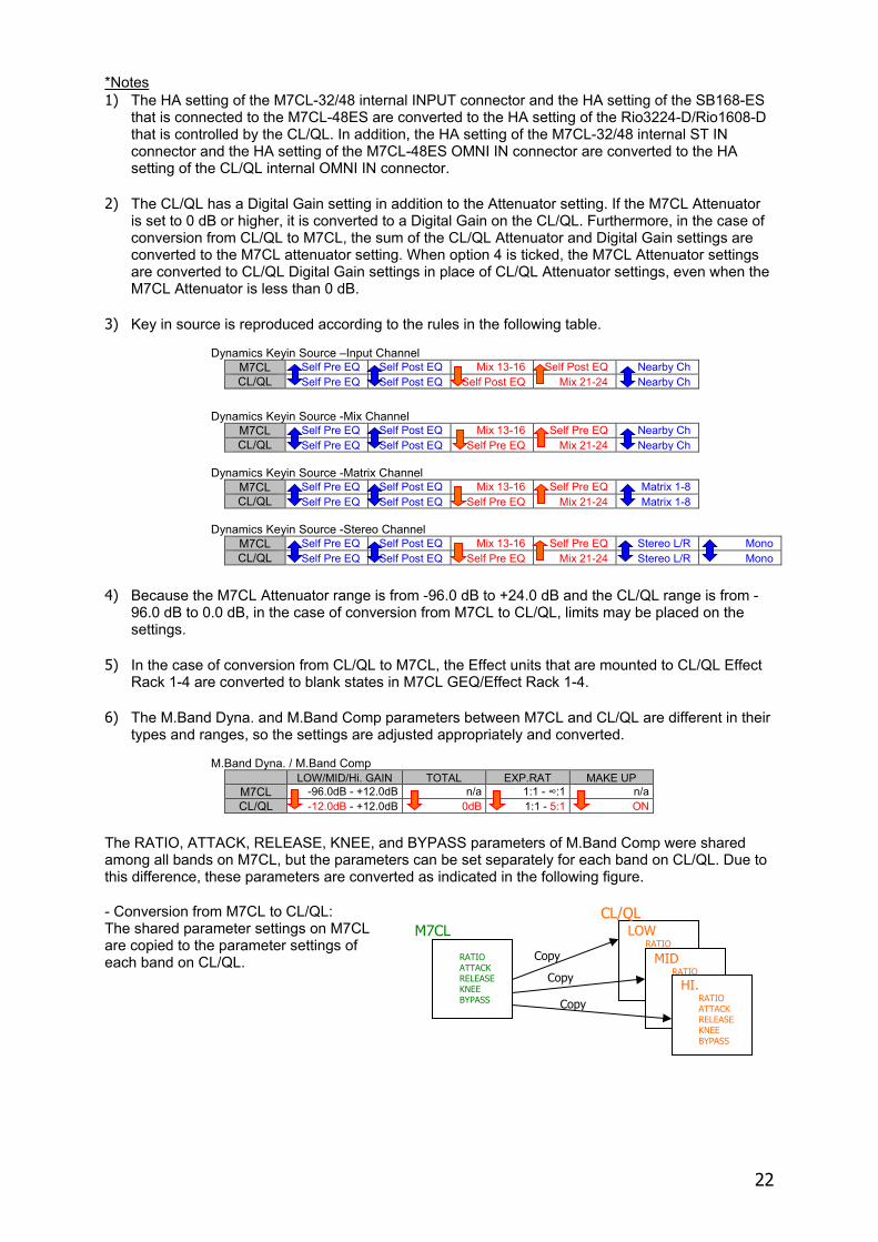
*Notes 1) The HA setting of the M7CL-32/48 internal INPUT connector and the HA setting of the SB168-ES
that is connected to the M7CL-48ES are converted to the HA setting of the Rio3224-D/Rio1608-D that is controlled by the CL/QL. In addition, the HA setting of the M7CL-32/48 internal ST IN connector and the HA setting of the M7CL-48ES OMNI IN connector are converted to the HA setting of the CL/QL internal OMNI IN connector.
2) The CL/QL has a Digital Gain setting in addition to the Attenuator setting. If the M7CL Attenuator
is set to 0 dB or higher, it is converted to a Digital Gain on the CL/QL. Furthermore, in the case of conversion from CL/QL to M7CL, the sum of the CL/QL Attenuator and Digital Gain settings are converted to the M7CL attenuator setting. When option 4 is ticked, the M7CL Attenuator settings are converted to CL/QL Digital Gain settings in place of CL/QL Attenuator settings, even when the M7CL Attenuator is less than 0 dB.
3) Key in source is reproduced according to the rules in the following table.
Dynamics Keyin Source –Input Channel M7CL Self Pre EQ Self Post EQ Mix 13-16 Self Post EQ Nearby Ch CL/QL Self Pre EQ Self Post EQ Self Post EQ Mix 21-24 Nearby Ch
Dynamics Keyin Source -Mix Channel
M7CL Self Pre EQ Self Post EQ Mix 13-16 Self Pre EQ Nearby Ch CL/QL Self Pre EQ Self Post EQ Self Pre EQ Mix 21-24 Nearby Ch
Dynamics Keyin Source -Matrix Channel
M7CL Self Pre EQ Self Post EQ Mix 13-16 Self Pre EQ Matrix 1-8 CL/QL Self Pre EQ Self Post EQ Self Pre EQ Mix 21-24 Matrix 1-8
Dynamics Keyin Source -Stereo Channel
M7CL Self Pre EQ Self Post EQ Mix 13-16 Self Pre EQ Stereo L/R Mono CL/QL Self Pre EQ Self Post EQ Self Pre EQ Mix 21-24 Stereo L/R Mono
4) Because the M7CL Attenuator range is from -96.0 dB to +24.0 dB and the CL/QL range is from -
96.0 dB to 0.0 dB, in the case of conversion from M7CL to CL/QL, limits may be placed on the settings.
5) In the case of conversion from CL/QL to M7CL, the Effect units that are mounted to CL/QL Effect
Rack 1-4 are converted to blank states in M7CL GEQ/Effect Rack 1-4. 6) The M.Band Dyna. and M.Band Comp parameters between M7CL and CL/QL are different in their
types and ranges, so the settings are adjusted appropriately and converted. M.Band Dyna. / M.Band Comp
LOW/MID/Hi. GAIN TOTAL EXP.RAT MAKE UP M7CL -96.0dB - +12.0dB n/a 1:1 - ∞:1 n/a CL/QL -12.0dB - +12.0dB 0dB 1:1 - 5:1 ON
The RATIO, ATTACK, RELEASE, KNEE, and BYPASS parameters of M.Band Comp were shared among all bands on M7CL, but the parameters can be set separately for each band on CL/QL. Due to this difference, these parameters are converted as indicated in the following figure. - Conversion from M7CL to CL/QL: The shared parameter settings on M7CL are copied to the parameter settings of each band on CL/QL.
LOW RATIO
MID RATIO
HI. RATIO ATTACK RELEASE KNEE BYPASS
RATIO ATTACK RELEASE KNEE BYPASS Copy
Copy
Copy
M7CL CL/QL
23
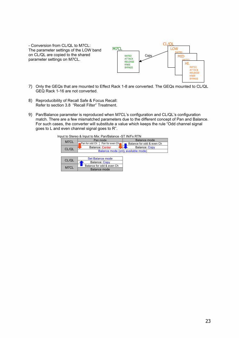
- Conversion from CL/QL to M7CL: The parameter settings of the LOW band on CL/QL are copied to the shared parameter settings on M7CL. 7) Only the GEQs that are mounted to Effect Rack 1-8 are converted. The GEQs mounted to CL/QL
GEQ Rack 1-16 are not converted. 8) Reproducibility of Recall Safe & Focus Recall:
Refer to section 3.8 “Recall Filter” Treatment. 9) Pan/Balance parameter is reproduced when M7CL’s configuration and CL/QL’s configuration
match. There are a few mismatched parameters due to the different concept of Pan and Balance. For such cases, the converter will substitute a value which keeps the rule “Odd channel signal goes to L and even channel signal goes to R”.
Input to Stereo & Input to Mix: Pan/Balance -ST IN/Fx RTN
M7CL Pan mode Balance mode Pan for odd Ch Pan for even Ch Balance for odd & even Ch
CL/QL Balance: Center Balance: Copy Balance mode (only available mode)
CL/QL Set Balance mode Balance: Copy
M7CL Balance for odd & even Ch Balance mode
LOW RATIO
MID RATIO
HI. RATIO ATTACK RELEASE KNEE BYPASS
RATIO ATTACK RELEASE KNEE BYPASS
Copy
M7CL CL/QL
24
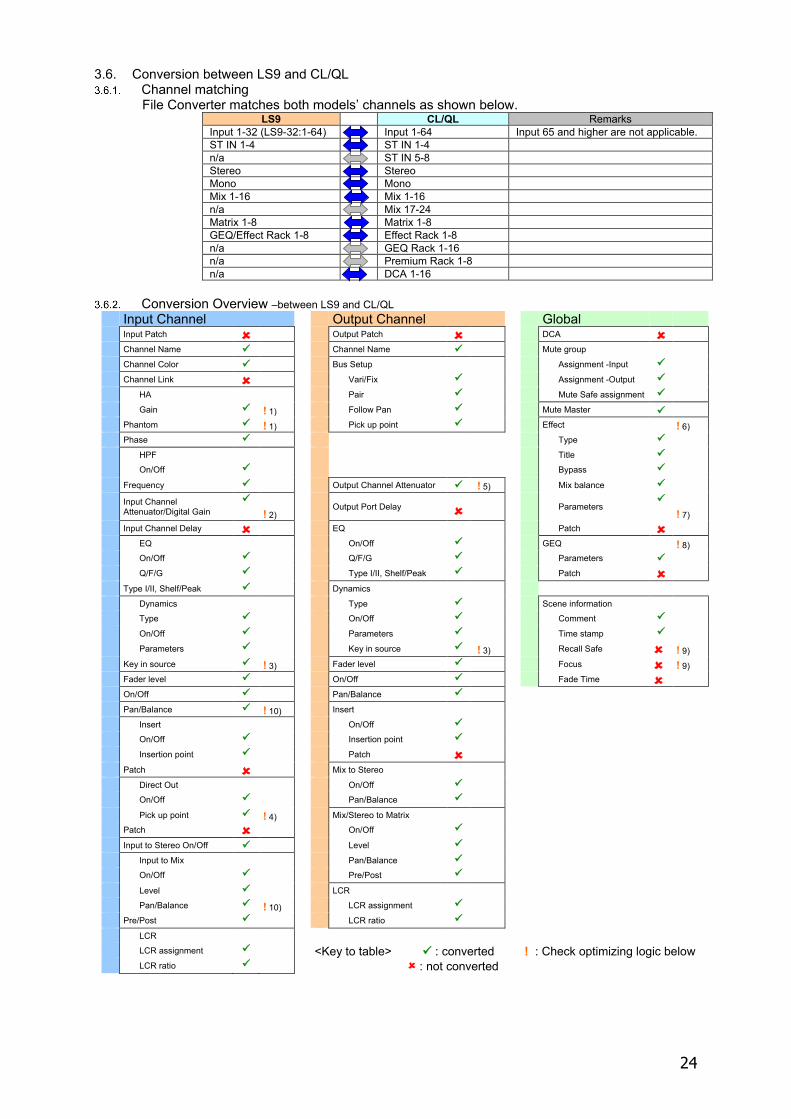
3.6. Conversion between LS9 and CL/QL Channel matching
File Converter matches both models’ channels as shown below. LS9 CL/QL Remarks
Input 1-32 (LS9-32:1-64) Input 1-64 Input 65 and higher are not applicable. ST IN 1-4 ST IN 1-4 n/a ST IN 5-8 Stereo Stereo Mono Mono Mix 1-16 Mix 1-16 n/a Mix 17-24 Matrix 1-8 Matrix 1-8 GEQ/Effect Rack 1-8 Effect Rack 1-8 n/a GEQ Rack 1-16 n/a Premium Rack 1-8 n/a DCA 1-16
Conversion Overview –between LS9 and CL/QL
Input Channel Output Channel Global Input Patch Output Patch DCA Channel Name Channel Name Mute group Channel Color Bus Setup Assignment -Input Channel Link Vari/Fix Assignment -Output HA Pair Mute Safe assignment Gain ! 1) Follow Pan Mute Master Phantom ! 1) Pick up point Effect ! 6) Phase Type HPF Title On/Off Bypass Frequency Output Channel Attenuator ! 5) Mix balance
Input Channel Attenuator/Digital Gain
! 2) Output Port Delay Parameters
! 7) Input Channel Delay EQ Patch EQ On/Off GEQ ! 8) On/Off Q/F/G Parameters Q/F/G Type I/II, Shelf/Peak Patch Type I/II, Shelf/Peak Dynamics Dynamics Type Scene information Type On/Off Comment On/Off Parameters Time stamp Parameters Key in source ! 3) Recall Safe ! 9) Key in source ! 3) Fader level Focus ! 9) Fader level On/Off Fade Time On/Off Pan/Balance Pan/Balance ! 10) Insert Insert On/Off On/Off Insertion point Insertion point Patch Patch Mix to Stereo Direct Out On/Off On/Off Pan/Balance Pick up point ! 4) Mix/Stereo to Matrix Patch On/Off Input to Stereo On/Off Level Input to Mix Pan/Balance On/Off Pre/Post Level LCR Pan/Balance ! 10) LCR assignment Pre/Post LCR ratio LCR LCR assignment <Key to table> : converted ! : Check optimizing logic below LCR ratio : not converted
25
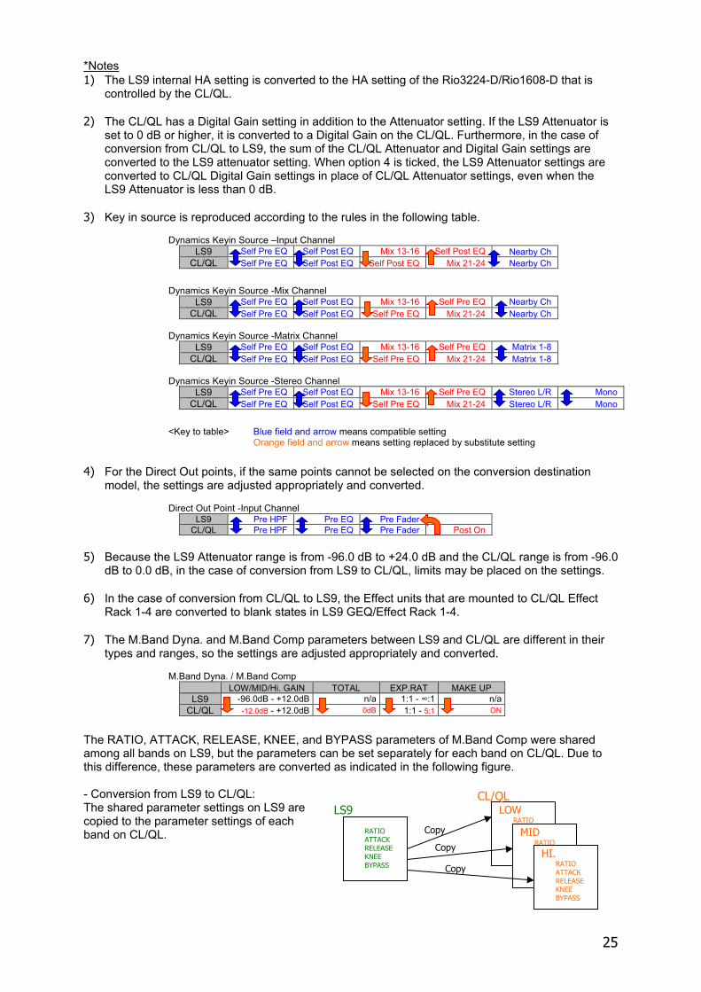
*Notes 1) The LS9 internal HA setting is converted to the HA setting of the Rio3224-D/Rio1608-D that is
controlled by the CL/QL. 2) The CL/QL has a Digital Gain setting in addition to the Attenuator setting. If the LS9 Attenuator is
set to 0 dB or higher, it is converted to a Digital Gain on the CL/QL. Furthermore, in the case of conversion from CL/QL to LS9, the sum of the CL/QL Attenuator and Digital Gain settings are converted to the LS9 attenuator setting. When option 4 is ticked, the LS9 Attenuator settings are converted to CL/QL Digital Gain settings in place of CL/QL Attenuator settings, even when the LS9 Attenuator is less than 0 dB.
3) Key in source is reproduced according to the rules in the following table.
Dynamics Keyin Source –Input Channel LS9 Self Pre EQ Self Post EQ Mix 13-16 Self Post EQ Nearby Ch
CL/QL Self Pre EQ Self Post EQ Self Post EQ Mix 21-24 Nearby Ch
Dynamics Keyin Source -Mix Channel
LS9 Self Pre EQ Self Post EQ Mix 13-16 Self Pre EQ Nearby Ch CL/QL Self Pre EQ Self Post EQ Self Pre EQ Mix 21-24 Nearby Ch
Dynamics Keyin Source -Matrix Channel
LS9 Self Pre EQ Self Post EQ Mix 13-16 Self Pre EQ Matrix 1-8 CL/QL Self Pre EQ Self Post EQ Self Pre EQ Mix 21-24 Matrix 1-8
Dynamics Keyin Source -Stereo Channel
LS9 Self Pre EQ Self Post EQ Mix 13-16 Self Pre EQ Stereo L/R Mono CL/QL Self Pre EQ Self Post EQ Self Pre EQ Mix 21-24 Stereo L/R Mono
<Key to table> Blue field and arrow means compatible setting
Orange field and arrow means setting replaced by substitute setting 4) For the Direct Out points, if the same points cannot be selected on the conversion destination
model, the settings are adjusted appropriately and converted. Direct Out Point -Input Channel
LS9 Pre HPF Pre EQ Pre Fader CL/QL Pre HPF Pre EQ Pre Fader Post On
5) Because the LS9 Attenuator range is from -96.0 dB to +24.0 dB and the CL/QL range is from -96.0
dB to 0.0 dB, in the case of conversion from LS9 to CL/QL, limits may be placed on the settings. 6) In the case of conversion from CL/QL to LS9, the Effect units that are mounted to CL/QL Effect
Rack 1-4 are converted to blank states in LS9 GEQ/Effect Rack 1-4. 7) The M.Band Dyna. and M.Band Comp parameters between LS9 and CL/QL are different in their
types and ranges, so the settings are adjusted appropriately and converted. M.Band Dyna. / M.Band Comp
LOW/MID/Hi. GAIN TOTAL EXP.RAT MAKE UP LS9 -96.0dB - +12.0dB n/a 1:1 - ∞:1 n/a
CL/QL -12.0dB - +12.0dB 0dB 1:1 - 5:1 ON
The RATIO, ATTACK, RELEASE, KNEE, and BYPASS parameters of M.Band Comp were shared among all bands on LS9, but the parameters can be set separately for each band on CL/QL. Due to this difference, these parameters are converted as indicated in the following figure. - Conversion from LS9 to CL/QL: The shared parameter settings on LS9 are copied to the parameter settings of each band on CL/QL.
LOW RATIO
MID RATIO
HI. RATIO ATTACK RELEASE KNEE BYPASS
RATIO ATTACK RELEASE KNEE BYPASS Copy
Copy
Copy
LS9 CL/QL
26
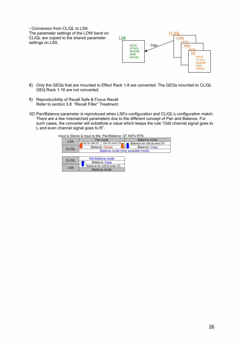
- Conversion from CL/QL to LS9: The parameter settings of the LOW band on CL/QL are copied to the shared parameter settings on LS9. 8) Only the GEQs that are mounted to Effect Rack 1-8 are converted. The GEQs mounted to CL/QL
GEQ Rack 1-16 are not converted. 9) Reproducibility of Recall Safe & Focus Recall
Refer to section 3.8 “Recall Filter” Treatment. 10) Pan/Balance parameter is reproduced when LS9’s configuration and CL/QL’s configuration match.
There are a few mismatched parameters due to the different concept of Pan and Balance. For such cases, the converter will substitute a value which keeps the rule “Odd channel signal goes to L and even channel signal goes to R”.
Input to Stereo & Input to Mix: Pan/Balance -ST IN/Fx RTN
LS9 Pan mode Balance mode Pan for odd Ch Pan for even Ch Balance for odd & even Ch
CL/QL Balance: Center Balance: Copy Balance mode (only available mode)
CL/QL Set Balance mode Balance: Copy
LS9 Balance for odd & even Ch Balance mode
LOW RATIO
MID RATIO
HI. RATIO ATTACK RELEASE KNEE BYPASS
RATIO ATTACK RELEASE KNEE BYPASS
Copy
LS9 CL/QL
27
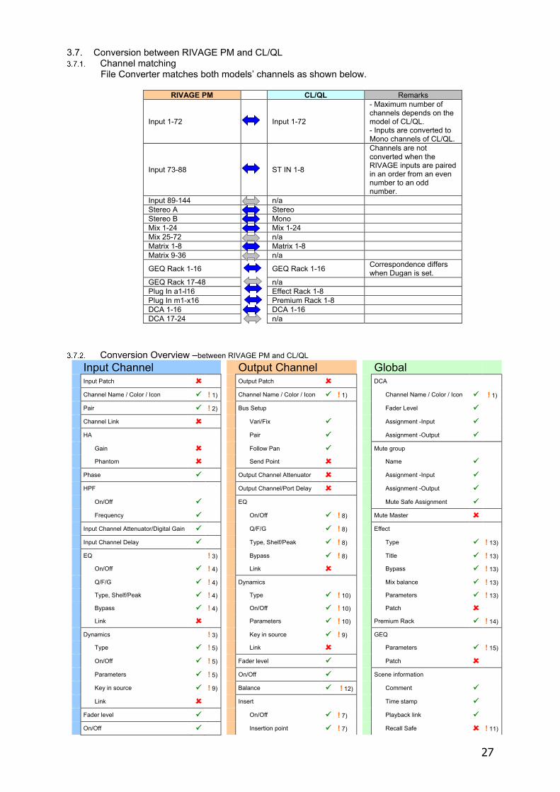
3.7. Conversion between RIVAGE PM and CL/QL Channel matching
File Converter matches both models’ channels as shown below.
RIVAGE PM CL/QL Remarks
Input 1-72 Input 1-72
- Maximum number of channels depends on the model of CL/QL. - Inputs are converted to Mono channels of CL/QL.
Input 73-88 ST IN 1-8
Channels are not converted when the RIVAGE inputs are paired in an order from an even number to an odd number.
Input 89-144 n/a Stereo A Stereo Stereo B Mono Mix 1-24 Mix 1-24 Mix 25-72 n/a Matrix 1-8 Matrix 1-8 Matrix 9-36 n/a
GEQ Rack 1-16 GEQ Rack 1-16 Correspondence differs when Dugan is set.
GEQ Rack 17-48 n/a Plug In a1-l16 Effect Rack 1-8 Plug In m1-x16 Premium Rack 1-8 DCA 1-16 DCA 1-16 DCA 17-24 n/a
Conversion Overview –between RIVAGE PM and CL/QL
Input Channel Output Channel Global Input Patch Output Patch DCA
Channel Name / Color / Icon ! 1) Channel Name / Color / Icon ! 1) Channel Name / Color / Icon ! 1)
Pair ! 2) Bus Setup Fader Level
Channel Link Vari/Fix Assignment -Input
HA Pair Assignment -Output
Gain Follow Pan Mute group Phantom Send Point Name
Phase Output Channel Attenuator Assignment -Input
HPF Output Channel/Port Delay Assignment -Output
On/Off EQ Mute Safe Assignment
Frequency On/Off ! 8) Mute Master
Input Channel Attenuator/Digital Gain Q/F/G ! 8) Effect
Input Channel Delay Type, Shelf/Peak ! 8) Type ! 13)
EQ ! 3) Bypass ! 8) Title ! 13) On/Off ! 4) Link Bypass ! 13)
Q/F/G ! 4) Dynamics Mix balance ! 13) Type, Shelf/Peak ! 4) Type ! 10) Parameters ! 13) Bypass ! 4) On/Off ! 10) Patch Link Parameters ! 10) Premium Rack ! 14)
Dynamics ! 3) Key in source ! 9) GEQ Type ! 5) Link Parameters ! 15)
On/Off ! 5) Fader level Patch
Parameters ! 5) On/Off Scene information
Key in source ! 9) Balance ! 12) Comment
Link Insert Time stamp
Fader level On/Off ! 7) Playback link
On/Off Insertion point ! 7) Recall Safe ! 11)
28
Input Channel Output Channel Global Pan/Balance ! 6) Patch Focus / Selective Recall ! 11)
Insert Overlay On/Off ! 7) Mix to Stereo Fade Time Insertion point ! 7) On/Off
Patch Pan/Balance
Direct Out Mix/Stereo to Matrix
On/Off On/Off
Pick up point ! 7) Level
Patch Pan/Balance ! 16)
Input to Stereo On/Off Pre/Post
Input to Mix LCR
On/Off LCR assignment
Level LCR ratio
Pan/Balance ! 6) Surround
Pre/Post Mode Stereo, 5.1
LCR 3.1, 6.1
LCR assignment
LCR ratio
Surround
L,R,C,LFE,Ls,Rs ON
PAN
Divergence
LFE Level <Key to table> : converted ! : Check optimizing logic below : not converted
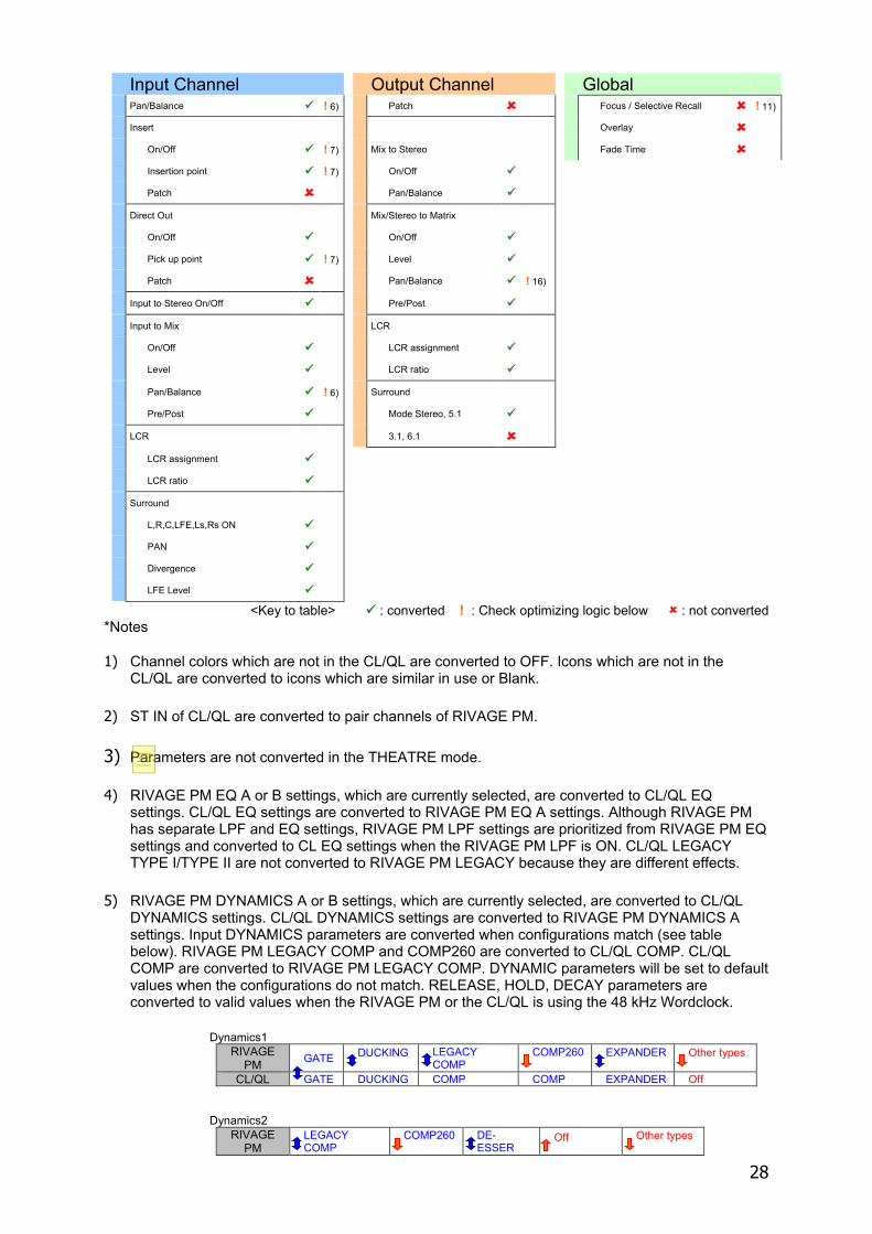
*Notes 1) Channel colors which are not in the CL/QL are converted to OFF. Icons which are not in the
CL/QL are converted to icons which are similar in use or Blank. 2) ST IN of CL/QL are converted to pair channels of RIVAGE PM. 3) Parameters are not converted in the THEATRE mode. 4) RIVAGE PM EQ A or B settings, which are currently selected, are converted to CL/QL EQ
settings. CL/QL EQ settings are converted to RIVAGE PM EQ A settings. Although RIVAGE PM has separate LPF and EQ settings, RIVAGE PM LPF settings are prioritized from RIVAGE PM EQ settings and converted to CL EQ settings when the RIVAGE PM LPF is ON. CL/QL LEGACY TYPE I/TYPE II are not converted to RIVAGE PM LEGACY because they are different effects.
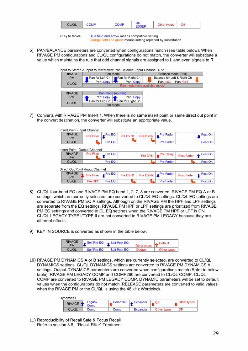
5) RIVAGE PM DYNAMICS A or B settings, which are currently selected, are converted to CL/QL
DYNAMICS settings. CL/QL DYNAMICS settings are converted to RIVAGE PM DYNAMICS A settings. Input DYNAMICS parameters are converted when configurations match (see table below). RIVAGE PM LEGACY COMP and COMP260 are converted to CL/QL COMP. CL/QL COMP are converted to RIVAGE PM LEGACY COMP. DYNAMIC parameters will be set to default values when the configurations do not match. RELEASE, HOLD, DECAY parameters are converted to valid values when the RIVAGE PM or the CL/QL is using the 48 kHz Wordclock.
Dynamics1
RIVAGE PM GATE DUCKING LEGACY
COMP COMP260 EXPANDER Other types
CL/QL GATE DUCKING COMP COMP EXPANDER Off Dynamics2
RIVAGE PM
LEGACY COMP
COMP260 DE-ESSER
Off Other types
29
CL/QL COMP COMP DE-ESSER Other types Off
<Key to table> Blue field and arrow means compatible setting
Orange field and arrow means setting replaced by substitution 6) PAN/BALANCE parameters are converted when configurations match (see table below). When
RIVAGE PM configurations and CL/QL configurations do not match, the converter will substitute a value which maintains the rule that odd channel signals are assigned to L and even signals to R.
Input to Stereo & Input to Mix/Matrix: Pan/Balance -Input Channel 1-72
RIVAGE PM
Pan mode Balance mode (Pair) Pan for Left Ch Pan for Right Ch Balance for Left & Right Ch
CL/QL Pan: Copy Pan: Copy Pan: L63 Pan: R63 Pan mode (only available mode)
RIVAGE
PM Pan mode (no Pair)
Pan: Copy Pan: Copy
CL/QL Pan for Left Ch Pan for Right Ch Pan mode
7) Converts with RIVAGE PM Insert 1. When there is no same insert point or same direct out point in
the convert destination, the converter will substitute an appropriate value.
Insert Point -Input Channel RIVAGE
PM Pre Filter Pre EQ Pre DYN1 Pre DYN2 Pre Fader Post On
CL/QL Pre EQ Pre Fader Post On Insert Point -Output Channel
RIVAGE PM
Pre Filter Pre EQ Pre DYN Pre Delay Post Fader Post On
CL/QL Pre EQ Pre Fader Post On Direct Out Point -Input Channel
RIVAGE PM Pre Filter Pre EQ Pre DYN1 Pre DYN2 Pre Fader Post Fader Post On
CL/QL Pre HPF Pre EQ Pre Fader Post On
8) CL/QL four-band EQ and RIVAGE PM EQ band 1, 2, 7, 8 are converted. RIVAGE PM EQ A or B
settings, which are currently selected, are converted to CL/QL EQ settings. CL/QL EQ settings are converted to RIVAGE PM EQ A settings. Although on the RIVAGE PM the HPF and LPF settings are separate from the EQ settings, RIVAGE PM HPF or LPF settings are prioritized from RIVAGE PM EQ settings and converted to CL EQ settings when the RIVAGE PM HPF or LPF is ON. CL/QL LEGACY TYPE I/TYPE II are not converted to RIVAGE PM LEGACY because they are different effects.
9) KEY IN SOURCE is converted as shown in the table below.
RIVAGE PM
Self Pre EQ Self Post EQ Other types
Default
CL/QL Self Pre EQ Self Post EQ Default Other types
10) RIVAGE PM DYNAMICS A or B settings, which are currently selected, are converted to CL/QL
DYNAMICS settings. CL/QL DYNAMICS settings are converted to RIVAGE PM DYNAMICS A settings. Output DYNAMICS parameters are converted when configurations match (Refer to below table). RIVAGE PM LEGACY COMP and COMP260 are converted to CL/QL COMP. CL/QL COMP are converted to RIVAGE PM LEGACY COMP. DYNAMIC parameters will be set to default values when the configurations do not match. RELEASE parameters are converted to valid values when the RIVAGE PM or the CL/QL is using the 48 kHz Wordclock.
Dynamics1
RIVAGE Legacy Comp
Comp260 Expander Off Other types
CL/QL Comp Comp Expander Other types Off
11) Reproducibility of Recall Safe & Focus Recall
Refer to section 3.8, “Recall Filter” Treatment.
30
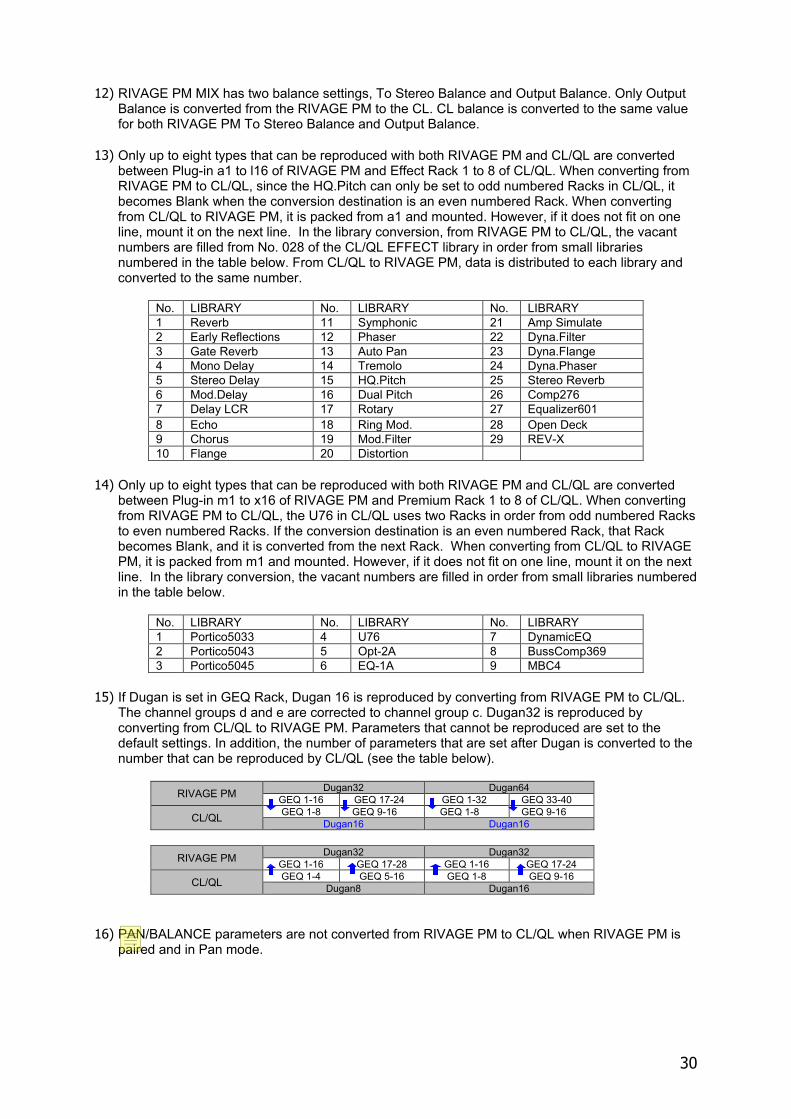
12) RIVAGE PM MIX has two balance settings, To Stereo Balance and Output Balance. Only Output
Balance is converted from the RIVAGE PM to the CL. CL balance is converted to the same value for both RIVAGE PM To Stereo Balance and Output Balance.
13) Only up to eight types that can be reproduced with both RIVAGE PM and CL/QL are converted between Plug-in a1 to l16 of RIVAGE PM and Effect Rack 1 to 8 of CL/QL. When converting from RIVAGE PM to CL/QL, since the HQ.Pitch can only be set to odd numbered Racks in CL/QL, it becomes Blank when the conversion destination is an even numbered Rack. When converting from CL/QL to RIVAGE PM, it is packed from a1 and mounted. However, if it does not fit on one line, mount it on the next line. In the library conversion, from RIVAGE PM to CL/QL, the vacant numbers are filled from No. 028 of the CL/QL EFFECT library in order from small libraries numbered in the table below. From CL/QL to RIVAGE PM, data is distributed to each library and converted to the same number.
No. LIBRARY No. LIBRARY No. LIBRARY 1 Reverb 11 Symphonic 21 Amp Simulate 2 Early Reflections 12 Phaser 22 Dyna.Filter 3 Gate Reverb 13 Auto Pan 23 Dyna.Flange 4 Mono Delay 14 Tremolo 24 Dyna.Phaser 5 Stereo Delay 15 HQ.Pitch 25 Stereo Reverb 6 Mod.Delay 16 Dual Pitch 26 Comp276 7 Delay LCR 17 Rotary 27 Equalizer601 8 Echo 18 Ring Mod. 28 Open Deck 9 Chorus 19 Mod.Filter 29 REV-X 10 Flange 20 Distortion
14) Only up to eight types that can be reproduced with both RIVAGE PM and CL/QL are converted
between Plug-in m1 to x16 of RIVAGE PM and Premium Rack 1 to 8 of CL/QL. When converting from RIVAGE PM to CL/QL, the U76 in CL/QL uses two Racks in order from odd numbered Racks to even numbered Racks. If the conversion destination is an even numbered Rack, that Rack becomes Blank, and it is converted from the next Rack. When converting from CL/QL to RIVAGE PM, it is packed from m1 and mounted. However, if it does not fit on one line, mount it on the next line. In the library conversion, the vacant numbers are filled in order from small libraries numbered in the table below.
No. LIBRARY No. LIBRARY No. LIBRARY 1 Portico5033 4 U76 7 DynamicEQ 2 Portico5043 5 Opt-2A 8 BussComp369 3 Portico5045 6 EQ-1A 9 MBC4
15) If Dugan is set in GEQ Rack, Dugan 16 is reproduced by converting from RIVAGE PM to CL/QL.
The channel groups d and e are corrected to channel group c. Dugan32 is reproduced by converting from CL/QL to RIVAGE PM. Parameters that cannot be reproduced are set to the default settings. In addition, the number of parameters that are set after Dugan is converted to the number that can be reproduced by CL/QL (see the table below).
RIVAGE PM Dugan32 Dugan64
GEQ 1-16 GEQ 17-24 GEQ 1-32 GEQ 33-40
CL/QL GEQ 1-8 GEQ 9-16 GEQ 1-8 GEQ 9-16 Dugan16 Dugan16
RIVAGE PM Dugan32 Dugan32
GEQ 1-16 GEQ 17-28 GEQ 1-16 GEQ 17-24
CL/QL GEQ 1-4 GEQ 5-16 GEQ 1-8 GEQ 9-16 Dugan8 Dugan16
16) PAN/BALANCE parameters are not converted from RIVAGE PM to CL/QL when RIVAGE PM is paired and in Pan mode.
31
3.8. “Recall Filter” Treatment
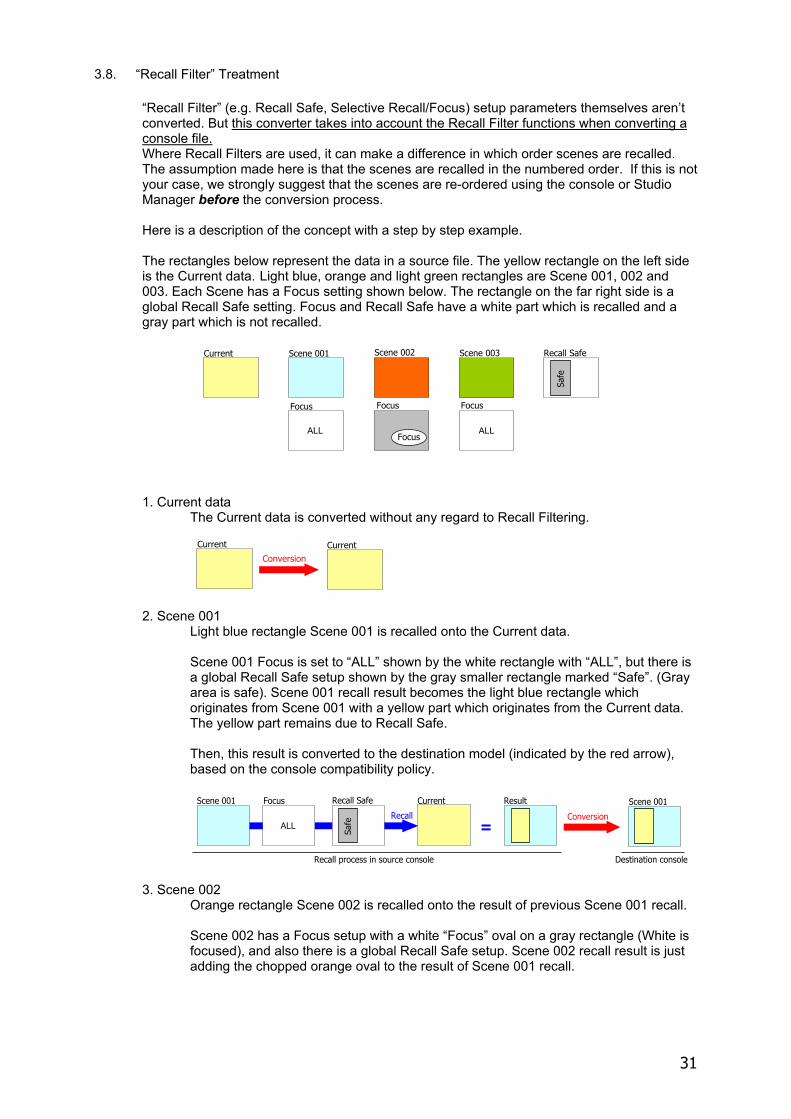
“Recall Filter” (e.g. Recall Safe, Selective Recall/Focus) setup parameters themselves aren’t converted. But this converter takes into account the Recall Filter functions when converting a console file. Where Recall Filters are used, it can make a difference in which order scenes are recalled. The assumption made here is that the scenes are recalled in the numbered order. If this is not your case, we strongly suggest that the scenes are re-ordered using the console or Studio Manager before the conversion process. Here is a description of the concept with a step by step example. The rectangles below represent the data in a source file. The yellow rectangle on the left side is the Current data. Light blue, orange and light green rectangles are Scene 001, 002 and 003. Each Scene has a Focus setting shown below. The rectangle on the far right side is a global Recall Safe setting. Focus and Recall Safe have a white part which is recalled and a gray part which is not recalled.
1. Current data
The Current data is converted without any regard to Recall Filtering.
2. Scene 001
Light blue rectangle Scene 001 is recalled onto the Current data.
Scene 001 Focus is set to “ALL” shown by the white rectangle with “ALL”, but there is a global Recall Safe setup shown by the gray smaller rectangle marked “Safe”. (Gray area is safe). Scene 001 recall result becomes the light blue rectangle which originates from Scene 001 with a yellow part which originates from the Current data. The yellow part remains due to Recall Safe.
Then, this result is converted to the destination model (indicated by the red arrow), based on the console compatibility policy.
3. Scene 002 Orange rectangle Scene 002 is recalled onto the result of previous Scene 001 recall.
Scene 002 has a Focus setup with a white “Focus” oval on a gray rectangle (White is focused), and also there is a global Recall Safe setup. Scene 002 recall result is just adding the chopped orange oval to the result of Scene 001 recall.
Focus
Scene 001Current Scene 002 Scene 003
Focus
Focus Focus
ALLALL
Recall Safe
Safe
CurrentCurrentConversion
RecallScene 001 Scene 001Focus
ALL
Current Result
=Conversion
Recall Safe
Safe
Recall process in source console Destination console
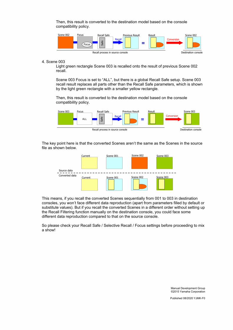
Then, this result is converted to the destination model based on the console compatibility policy.
4. Scene 003
Light green rectangle Scene 003 is recalled onto the result of previous Scene 002 recall. Scene 003 Focus is set to “ALL”, but there is a global Recall Safe setup. Scene 003 recall result replaces all parts other than the Recall Safe parameters, which is shown by the light green rectangle with a smaller yellow rectangle.
Then, this result is converted to the destination model based on the console compatibility policy.
The key point here is that the converted Scenes aren’t the same as the Scenes in the source file as shown below.
This means, if you recall the converted Scenes sequentially from 001 to 003 in destination consoles, you won’t face different data reproduction (apart from parameters filled by default or substitute values). But if you recall the converted Scenes in a different order without setting up the Recall Filtering function manually on the destination console, you could face some different data reproduction compared to that on the source console. So please check your Recall Safe / Selective Recall / Focus settings before proceeding to mix a show!
RecallScene 002 Scene 002Recall Safe
Safe
Focus
Focus =Previous Result Result
Conversion
Recall process in source console Destination console
Recall
Scene 003 Scene 003Focus
=Previous Result Result
ALLConversion
Recall Safe
Safe
Recall process in source console Destination console
Scene 001Current Scene 002 Scene 003
Scene 001 Scene 002 Scene 003Current
Source data
Converted data
Manual Development Group ©2015 Yamaha Corporation
Published 08/2020 YJMK-F0