mx-16 - rc car, rc helicopter, quadcopter and rc planes · rc system components, as any such...
TRANSCRIPT

Programming Manual
33116.mx-16 HoTT.2.gb
H O P P I N G T E L E M E T R Y T R A N S M I S S I O N
mx-16
2 Contents
Digital trims .................................................................. 40Fixed-wing model aircraft............................................. 42
Receiver socket sequence ............................... 43/44Model helicopters ........................................................ 46
Receiver socket sequence .................................... 47
Program descriptionsSetting up a new model memory ................................. 48“Model memories” ...................................................... 52“Base settings” (model)
Fixed-wing model aircraft ...................................... 56Binding receivers ............................................. 61Range-checking .............................................. 62
Model helicopter .................................................... 64Binding receivers ............................................. 70Range-checking .............................................. 70
“Servo settings” .......................................................... 72
“Transmitter control settings”Fixed-wing model aircraft ...................................... 74Model helicopter .................................................... 76
Throttle limit function ....................................... 79Basic idle setting ............................................. 79
“D/R Expo”Fixed-wing model aircraft ...................................... 82Model helicopter .................................................... 84
“Phase trim” (fi xed-wing) ............................................ 86
What is a mixer? .......................................................... 88“Wing mixer” .............................................................. 88“Heli mixer” ................................................................ 94
Setting up throttle and collective pitch curves ..... 100Auto-rotation setting ............................................ 104
General notes re. freely programmable mixers .......... 106“Free mixers” ........................................................... 107
General InformationSafety Notes .................................................................. 3Safety notes and handling instructions relating to Nickel-Metal-Hydride rechargeable batteries ............ 8Foreword ...................................................................... 10Description of radio control set .................................... 11Recommended battery chargers ................................. 13Transmitter power supply ............................................. 14Receiver power supply ................................................ 16Environmental protection notes ................................... 16Adjusting the stick length ............................................. 17Opening the transmitter case ...................................... 17Changing the stick mode ............................................. 18Description of transmitter............................................. 20
Transmitter controls ............................................... 20Rear of transmitter ................................................. 21Headphone socket ................................................ 21Mini-USB socket .................................................... 21Data socket ........................................................... 21DSC (Direct Servo Control) ................................... 22Data storage / card slot ......................................... 22Screen and keypad ............................................... 24Operating the “Data Terminal” ............................... 25Short-cuts .............................................................. 25Language selection, screen contrast ..................... 26On-screen warnings .............................................. 28On-screen function fi elds....................................... 28Position indicator, rotary controls CTRL 7 + 8 ....... 29Input lock ............................................................... 29
Using the transmitter for the fi rst time .......................... 30Using the receiver for the fi rst time .............................. 32Installation notes .......................................................... 34
Receiving system power supply ............................ 35Defi nition of terms ....................................................... 38Switch and transmitter control assignment .................. 39
Contents
Examples............................................................. 111“Swashplate mixers” ............................................... 112“Servo display” ......................................................... 113“Basic settings” ........................................................ 114“Fail-Safe” ................................................................. 116“Telemetry” ............................................................... 117
Setting & Data view ............................................. 118Satellite operation with two receivers ............ 126
Simple data view ................................................. 128RF status view ..................................................... 130Voice trigger ........................................................ 131
“Trainer mode” ......................................................... 134Wiring diagrams .................................................. 137Wireless HoTT system ........................................ 138
“Info” ........................................................................ 142
Programming examplesIntroduction ................................................................ 144Fixed-wing model aircraft
First steps ............................................................ 146Including an electric power system ..................... 150E-motor and Butterfl y (crow) using Ch1 stick ...... 152Operating timers .................................................. 155Use of fl ight phases ............................................. 156Servos running in parallel .................................... 157
Deltas and fl ying wings .............................................. 158F3A models ............................................................... 162Model helicopters ...................................................... 166
AppendixAppendix .................................................................... 174Conformity declaration ............................................... 177FCC Information ........................................................ 178Guarantee certifi cate ................................................. 179
3Safety Notes
We all want you to have many hours of pleasure in our mutual hobby of modelling, and safety is an important aspect of this. It is absolutely essential that you read right through these instructions and take careful note of all our safety recommendations. We also strongly recommend that you register without delay at http://www.graupner.de/en/service/product_registration, as this ensures that you automatically receive the latest information relating to your product by e-mail.If you are a beginner to the world of radio-controlled model aircraft, boats and cars, we strongly advise that you seek out an experienced modeller in your fi eld, and ask him or her for help and advice.If you ever dispose of this transmitter, these instructions must be passed on to the new owner.
ApplicationThis radio control system may only be used for the purpose for which the manufacturer intended it, i. e. for operating radio-controlled models which do not carry hu-mans. No other type of use is approved or permissible.
Safety notesSAFETY IS NO ACCIDENT
andRADIO-CONTROLLED MODELS
ARE NOT PLAYTHINGSEven small models can cause serious personal injury and damage to property if they are handled incompe-tently, or if an accident occurs due to the fault of others.Technical problems in electrical and mechanical sys-tems can cause motors to rev up or burst into life unex-pectedly, with the result that parts may fl y off at great speed, causing considerable injury.Short-circuits of all kinds must be avoided at all times.
Short-circuits can easily destroy parts of the radio con-trol system, but even more dangerous is the acute risk of fi re and explosion, depending on the circumstances and the energy content of the batteries.Aircraft and boat propellers, helicopter rotors, open gearboxes and all other rotating parts which are driven by a motor or engine represent a constant injury hazard. Do not touch these items with any object or part of your body. Remember that a propeller spinning at high speed can easily slice off a fi nger! Ensure that no other object can make contact with the driven components.Never stand in the primary danger zone, i. e. in the rota-tional plane of the propeller or other rotating parts, when the motor is running or the drive battery is connected.Please note that a glowplug engine or electric motor could burst into life accidentally if the receiving system is switched on when you are transmitting the transmitter. To be on the safe side, disconnect the fueltank or the fl ight battery.Protect all electronic equipment from dust, dirt, damp, and foreign bodies. Avoid subjecting the equipment to vibration and excessive heat or cold. Radio control equipment should only be used in “normal” ambient temperatures, i. e. within the range -15°C to +55°C.Avoid subjecting the equipment to shock and pressure. Check the units at regular intervals for damage to cases and leads. Do not re-use any item which is damaged or has become wet, even after you have dried it out thor-oughly.Use only those components and accessories which we expressly recommend. Be sure to use only genuine matching Graupner connectors of the same design with contacts of the same material.When deploying cables ensure that they are not under
strain, are not tightly bent (kinked) or broken. Avoid sharp edges, as they can chafe through insulating materials.Before you use the system, check that all connectors are pushed home fi rmly. When disconnecting compo-nents, pull on the connectors themselves – not on the wires.It is not permissible to carry out any modifi cations to the RC system components, as any such changes invalidate both your operating licence and your insurance cover.
Installing the receiving systemIn a model aircraft the receiver must be packed in soft foam and stowed behind a stout bulkhead, and in a model boat or car it should be protected effectively from dust and spray.The receiver must not make direct contact with the fuselage, hull or chassis at any point, otherwise motor vibration and landing shocks will be transmitted directly to it. When installing the receiving system in a model with a glowplug or petrol engine, be sure to install all the components in well-protected positions, so that no exhaust gas or oil residues can reach the units and get inside them. This applies above all to the ON / OFF switch, which is usually installed in the outer skin of the model.Secure the receiver in such a way that the aerial, servo leads and switch harness are not under any strain. The receiver aerial should be at least 5 cm away from all large metal parts and any wiring which is not connected directly to the receiver. This includes steel and carbon fi bre components, servos, electric motors, fuel pumps, cabling of all kinds, etc..Ideally the receiver should be installed well away from
Safety NotesPlease read carefully!
4 Safety Notes
Safety Notes
Ensure that no metal parts are able to rub against each other, e. g. when controls are operated, when parts rotate, or when motor vibration affects the model. Metal-to-metal contact causes electrical “noise” which can interfere with the correct working of the receiver.
Directing the transmitter aerialTransmitter fi eld strength is at a minimum in an imagi-nary line extending straight out from the transmitter aerial. It is therefore fundamentally misguided to “point” the transmitter aerial at the model with the intention of obtaining good reception.When several radio control systems are in use on adja-cent channels, the pilots should always stand together in a loose group. Pilots who insist on standing away from the group endanger their own models as well as those of the other pilots.However, if two or more pilots operating 2.4 GHz radio control systems stand closer together than 5 m, the down-link channel may be swamped, triggering a very premature range warning. If this should occur, walk away from the other pilots until the range warning ceases again.
Pre-fl ight checkingBefore you switch on the receiver, ensure that the throt-tle stick is at the stop / idle end-point.
Always switch on the transmitter fi rst, and only then the receiver.
Always switch off the receiver fi rst, and only then the transmitter.
If you do not keep to this sequence, i. e. if the receiver is at any time switched on when “its” transmitter is switched OFF, then the receiver is wide open to signals
from other transmitters and any interference, and may respond. The model could then carry out uncontrolled movements, which could easily result in personal injury or damage to property. Please take particular care if your model is fi tted with a mechanical gyro: before you switch your receiver off, disconnect the power supply to ensure that the motor cannot run up to high speed accidentally.
As it runs down, the gyro can generate such a high voltage that the receiver picks up apparently valid throttle commands, and the motor could respond by unexpectedly bursting into life.
Range checkingBefore every session check that the system works properly in all respects, and has adequate range. Secure the model adequately, and ensure that no persons are standing in front of the model.Carry out at least one complete function check on the ground, followed by a complete simulated fl ight, in order to show up any errors in the system and the model’s programming. Be sure to read the notes on pages 62 and 70 in this regard.When operating a model, i. e. when fl ying or driving, do not operate the transmitter without the aerial fi tted. Check that the transmitter aerial is fi rmly seated.
Operating your model aircraft, helicopter, boat or carNever fl y directly over spectators or other pilots, and take care at all times not to endanger people or animals. Keep well clear of high-tension overhead cables. Never operate your model boat close to locks and full-size ves-sels. Model cars should never be run on public streets or motorways, footpaths, public squares etc..
any other installed equipment in the model, but in an easily accessible position. Under no circumstances al-low servo leads to run close to the aerial, far less coiled round it!Ensure that cables are fastened securely, so that they cannot move close to the receiver aerial when the model is fl ying.
Deploying the receiver aerial(s)The receiver and its aerials should be installed as far away as possible from all kinds of power system. If your model has a carbon fi bre fuselage, the aerial tips must always be deployed outside the fuselage. The orientation of the aerial(s) is not critical, but we recommend install-ing them vertically (upright) in the model. If the receiver features aerial diversity (two aerials), the second aerial should be arranged at 90° to the fi rst.
Installing the servosAlways install servos using the vibration-damping grommets supplied. The rubber grommets provide some degree of protection from mechanical shock and severe vibration.
Installing control linkagesThe basic rule is that all linkages should be installed in such a way that the pushrods move accurately, smoothly and freely. It is particularly important that all servo output arms can move to their full extent without fouling or rub-bing on anything, or being obstructed mechanically at any point in their travel.It is essential that you should be able to stop your motor at any time. With a glow motor this is achieved by adjust-ing the throttle so that the barrel closes completely when you move the throttle stick and trim to their end-points.
5Safety Notes
Checking the transmitter and receiver batteriesIt is essential to stop using the radio control system and recharge the batteries well before they are completely discharged. In the case of the transmitter this means – at the very latest – when the message “battery needs charging” appears on the screen, and you hear an audible warning signal.It is vital to check the state of the batteries at regular intervals – especially the receiver pack. When the bat-tery is almost fl at you may notice the servos running more slowly, but it is by no means safe to keep fl ying or running your model until this happens. Always replace or recharge the batteries in good time.Keep to the battery manufacturer’s instructions, and don’t leave the batteries on charge for longer than stated. Do not leave batteries on charge unsupervised.Never attempt to recharge dry cells, as they may ex-plode.Rechargeable batteries should always be recharged be-fore every session. When charging batteries it is impor-tant to avoid short-circuits. Do this by fi rst connecting the banana plugs on the charge lead to the charger, taking care to maintain correct polarity. Only then connect the charge lead to the transmitter or receiver battery.Disconnect all batteries and remove them from your model if you know you will not be using it in the near future.
Capacity and operating timesThis rule applies to all battery types: capacity diminishes with each charge. At low temperatures the battery’s internal resistance rises, and capacity falls. This means that its ability to deliver current and maintain voltage is reduced.
Frequent charging, and / or the use of maintenance programs, tends to cause a gradual reduction in battery capacity. We recommend that you check the capacity of all your rechargeable batteries at least every six months, and replace them if their performance has fallen off signifi cantly.Use only genuine Graupner rechargeable batteries!
Suppressing electric motorsAll conventional (brushed) electric motors generate sparks between the commutator and the brushes, which cause more or less serious interference to the radio control system, depending on the type of motor. If an RC system is to work correctly, it is therefore important to suppress the electric motors, and in electric-powered models it is essential that every motor should be effec-tively suppressed. Suppressor fi lters reliably eliminate such interference, and should always be fi tted where possible.Please read the notes and recommendations supplied by the motor manufacturer.Refer to the main Graupner FS catalogue or the Internet website at www.graupner.de for more information on suppressor fi lters.
Servo suppressor fi lter for extension leadsOrder No. 1040Servo suppressor fi lters are required if you are obliged to use long servo extension leads, as they eliminate the danger of de-tuning the receiver. The fi lter is connected directly to the receiver input. In very diffi cult cases a second fi lter can be used, positioned close to the servo.
Using electronic speed controllersThe basic rule is that the electronic speed controller
must be chosen to suit the size of the electric motor it is required to control.There is always a danger of overloading and possibly damaging the speed controller, but you can avoid this by ensuring that the controller’s current-handling capacity is at least half the motor’s maximum stall current.Particular care is called for if you are using a “hot” (i. e. upgrade) motor, as any low-turn motor (small number of turns on the winding) can draw many times its nominal current when stalled, and the high current will then burn out the speed controller.
Electrical ignition systemsIgnition systems for internal combustion engines can also produce interference, which has an adverse effect on the working of the radio control system.Electrical ignition systems should always be powered by a separate battery – not the receiver battery.Be sure to use effectively suppressed spark plugs and plug caps, and shielded ignition leads.Keep the receiving system an adequate distance away from the ignition system.
Static chargesLightning causes magnetic shock waves which can interfere with the operation of a radio control transmitter even if the thunderstorm actually occurs several kilome-tres away. For this reason …… cease fl ying operations immediately if you notice an electrical storm approaching. Static charges through the transmitter aerial can be life-threaten-ing!
CautionIn order to fulfi l the FCC RF radiation regulations •
6 Safety Notes
applicable to mobile transmitting apparatus, the equipment’s aerial must be at least 20 cm from any person when the system is in use. We therefore do not recommend using the equipment at a closer range than 20 cm.Ensure that no other transmitter is closer than 20 cm • from your equipment, in order to avoid adverse effects on the system’s electrical characteristics and radiation pattern.The radio control system should not be operated • until the Country setting has been set correctly at the transmitter. This is essential in order to fulfi l the requirements of various directives - FCC, ETSI, CE etc. Please refer to the instructions for your particular transmitter and receiver for details of this procedure.Check all working systems and carry out at least one • full range check on the ground before every fl ight, in order to show up any errors in the system and the model’s programming.Never make any changes to the programming of the • transmitter or receiver whilst operating a model.
Care and maintenanceDon’t use cleaning agents, petrol, water or other sol-vents to clean your equipment. If the case, the aerial etc. gets dirty, simply wipe the surfaces clean with a soft dry cloth.
Components and accessoriesAs manufacturers, the company of Graupner GmbH & Co. KG recommends the exclusive use of components and accessories which have been tested by Graupner and approved for their capability, function and safety. If you observe this rule, Graupner accepts responsibility for the product.
Graupner cannot accept liability for non-approved components or accessories made by other manu-facturers. It is not possible for Graupner to assess every individual item manufactured by other compa-nies, so we are unable to state whether such parts can be used without incurring a safety risk.
Liability exclusion / CompensationIt is not possible for Graupner to ensure that the user observes the installation and operation instructions, and the recommended conditions and methods when install-ing, operating, using and maintaining the radio control components. For this reason Graupner denies all liability for loss, damages or costs which arise through misuse or mishandling of this equipment, or are connected with such use in any way.Unless obliged by law, Graupner’s obligation to pay com-pensation, regardless of the legal argument employed, is limited to the invoice value of that quantity of Graup-ner products which were immediately involved in the event in which the damage occurred, unless the com-pany is deemed to have unlimited liability on account of deliberate or gross negligence.
Safety Notes
Environmental protectionThis symbol on the product, in the operating instructions or the packaging indicates that the product must not be discarded via the normal household refuse at the end of its useful life. Instead it must be taken to a collection point for the recycling of electrical and electronic ap-paratus.The materials can be re-used according to their identifi -cation code. You can make an important contribution to the protection of our shared environment by recycling
old equipment and making use of its basic materials.Dry and rechargeable batteries must be removed from the device and taken to the appropriate collection point.Please ask your local authority for the location of your nearest waste disposal site.
The sole purpose of this manual is to provide informa-tion; it is subject to amendment without prior notifi cation. Graupner accepts no responsibility or liability for errors or inaccuracies which may occur in the information section of this manual.

7For your notes

8 Safety Notes
Safety notes and handling instructions relating to Nickel-Metal-Hydride rechargeable batteriesAs with all sophisticated technical products, it is vitally important that you observe the following safety notes and handling instructions if you wish the equipment to operate safely and reliably for an extended period.
Safety notesIndividual cells and rechargeable batteries are not • playthings, and must be kept well away from children.Store rechargeable cells and batteries out of the reach of children.Check that the batteries are in perfect, serviceable • condition before every use. Do not re-use defective or damaged cells or batteries.Rechargeable cells and batteries must be used • within the specifi ed limits stated for the correspond-ing cell type.Do not heat, incinerate or short-circuit rechargea-• ble cells or batteries, and never charge them with excessive currents or reversed polarity.Never use rechargeable batteries consisting of • parallel-wired cells, combinations of old and new cells, cells of different construction, size, capaci-ty, make, brand or cell type.Batteries installed inside equipment should always be • removed from the device when it is not in use and not about to be used. Always keep equipment switched off in order to avoid deep-discharged cells. Batteries must be recharged in good time.The battery to be charged should be placed on a • non-infl ammable, heat-resistant, non-conductive surface for the whole of the charge period. Keep infl ammable and volatile objects and materials well clear of the charging area.Batteries must always be supervised when on •
charge. Never exceed the maximum fast-charge cur-rent specifi ed for the cell type in use.If the battery heats up to more than 60°C whilst on • charge, halt the charge process immediately and allow the pack to cool down to about 30°C.Never recharge a battery which is already charged, • hot, or not completely discharged.Do not make any modifi cations to batteries. Never • solder or weld directly to cells.If incorrectly handled, rechargeable batteries are at • risk of combustion, explosion, corrosive action and burns. Suitable extinguishing materials include fi re blankets, CO2 fi re extinguishers and sand.Escaped electrolyte is corrosive - do not allow it to • contact skin or eyes. In an emergency rinse the area immediately with plenty of clean water before seeking medical help.The cells’ air vents must never be blocked or sealed, • e. g. by solder. When soldering, the iron temperature should not exceed 220°C, and each joint should be completed in less than twenty seconds.To avoid cell deformation, do not exert excessive • mechanical pressure on battery cells.If a battery should be accidentally overcharged, use • the following procedure:Simply disconnect the battery and leave it on a non-infl ammable surface (e. g. stone fl oor) until it has cooled down. Never hold the battery in your hand, as there is a risk that cells might explode.Always observe the recommended rates for charging • and discharging.
General informationThe capacity of your rechargeable battery diminishes
with every charge / discharge process. Stored batteries may eventually exhibit reduced capacity.
StorageBatteries should not be stored in a completely dis-charged state. Store them in a dry enclosed space at an ambient temperature of +5°C to +25°C. If you are storing a battery for a period longer than four weeks, ensure that the cell voltage does not fall below 1.2 V
Balancing individual battery cellsTo balance new battery cells, i. e. to bring them all • to the same state of charge, charge them at what is known as the ‘normal’ rate until they are full. As a general guideline a fully discharged battery needs to be charged for a period of twelve hours at a current corresponding to one tenth of the capacity printed on the cell label (the “1/10C” method). After this treat-ment all the cells will be fully charged, and exhibit the same voltage. This method of balancing battery cells should be repeated after every ten fast-charge processes, so that the cells are repeatedly balanced; this helps to ensure an extended useful life for your batteries.If you have the facilities to discharge individual cells, • we recommend that you make use of this before every charge process. Otherwise the battery pack should be run down to a discharge voltage of 0.9 V per cell. For example, this corresponds to a fi nal discharge voltage of 3.6 V in the case of the four-cell pack used in the transmitter.
ChargingNi-MH batteries should only be charged using the speci-fi ed currents, charge times and temperature range, and should be supervised constantly when on charge. If you
9Safety Notes
do not have access to a suitable fast charger, i. e. one which allows you to set the charge current accurately, then the battery should always be recharged using the “normal” charge rate of 1/10C; see the example stated above.Wherever possible, transmitter batteries should always be recharged at the 1/10C rate, in order to avoid differences in cell states. The charge current must never exceed the maximum permissible value stated in the transmitter instructions.
Fast chargingIf your battery charger includes the facility to adjust • the Delta Peak charge cut-off voltage, set this value to 5 mV per cell. However, most chargers are set to a fi xed cut-off value of 15 … 20 mV per cell, which makes them suitable for use with both NiCd and NiMH batteries. If you are not sure about this, please refer to the operating instructions supplied with your charger, or ask at your local model shop whether your charger is also suitable for Ni-MH packs. If in any doubt, charge your batteries at half the stated maximum charge current.
DischargingAll rechargeable batteries sold by Graupner and GM-Racing are suitable for a maximum continuous current load of 6C … 13C, according to battery type (refer to the manufacturer’s specifi cation!). The higher the continuous current load, the shorter the batteries’ useful life.
Use your battery until its performance falls off, or until • the low voltage warning is triggered.Caution:When stored for a long period, the cell voltage should not be allowed to fall below 1.2 V. This means that
you may have to recharge the battery before stor-ing it.Refl ex charging and charge / discharge (cycle) • programs shorten the effective life of batteries unnec-essarily, and are only suitable for checking battery quality or “reviving” relatively old cells. It also makes no sense to charge / discharge a battery before using it - unless you simply wish to check its quality.
Disposal of exhausted dry and rechargeable batter-iesThe German Battery Order places a legal requirement on every consumer to return all used and exhausted dry cells and rechargeable batteries. It is prohibited to dispose of these items in the ordinary domestic waste. At no charge to the user, old dry and rechargeable batteries can be surrendered at local authority collec-tion points, Graupner retail outlets, and any other shop where dry and rechargeable batteries of the same type are sold. You can also send batteries supplied by us to the following address - with adequate pre-paid postage - for disposal:Graupner GmbH & Co. KGService: Gebrauchte Batterien (Used batteries)Henriettenstr. 94 - 96D-73230 Kirchheim unter TeckYou can make an important contribution to environmen-tal protection in this way.
Caution:Damaged batteries may require special packaging be-fore despatch, as some contain highly toxic materials!!!!!
10 Introduction
mx-16 the latest generation of radio control technology
HoTT (Hopping Telemetry Transmission) is the synthe-sis of expertise, engineering and world-wide testing by professional pilots. The equipment operates on the 2.4 GHz band, and offers bi-directional communication be-tween transmitter and receiver via a down-link channel integrated into the receiver.The mx-16 HoTT RC system is based on the Graup-ner/JR mc-24 computer radio control system which was introduced back in 1997. It has been developed specifi cally for the beginner, but the mx-16 HoTT is still capable of controlling all current model types with-out problem - whether fi xed-wing model or helicopter, model boat or car.In the area of fi xed-wing models and helicopters it is often necessary to employ complex mixer functions for the control surfaces or the swashplate actuation system. Computer technology enables you to activate a vast range of functions to cope with special model requirements – just by pressing a button. With the mx-16 HoTT all you do is select the appropriate model type, and the software then presents you automatically with the appropriate mixer and coupling functions. This means that the transmitter requires no additional mod-ules in order to implement complex coupled functions, and you can forget all about old-fashioned mechanical mixers in the model. The mx-16 HoTT provides an extremely high level of safety and reliability in use.The mx-16 HoTT offers twenty model memories, each of which can store model settings for different fl ight phases. Individual phases can be called up in fl ight simply by operating a switch, so that you can try out various settings quickly and without risk. This can be for test purposes or for varying parameters for different phases of fl ight.
The large graphic screen makes operating the trans-mitter a simple, intuitive process. Mixers and other functions can be displayed in graphic form, and this is extraordinarily helpful.The beginner quickly becomes familiar with the different functions thanks to the clear, logically arranged pro-gram structure. Four-way touch-sensitive buttons to left and right of the high-contrast screen are used to enter settings, allowing the user to exploit all the options he needs, in accordance with his experience in handling radio-controlled models.In theory the Graupner HoTT process allows more than 200 models to be operated simultaneously. Although in practice the mixed operation of different technical sys-tems in the 2.4 GHz ISM band – as required by the ap-proval regulations – reduces this number considerably. Generally, however, it will always be possible to operate even more models simultaneously on the 2.4 GHz band than on the 35 / 40 MHz frequency bands which we have used to date. However, the actual limiting factor – as it has always been – is likely to remain the size of the (air-) space available. The simple fact that no frequency control procedure is necessary equates to an enormous gain in safety, especially at fl ying sites such as gliding slopes where groups of pilots may be distributed over a large area, with nobody in overall control.The integral Telemetry menu provides a simple means of accessing data and programming HoTT receivers. For example, this method can be used to map receiver outputs, distribute control functions to multiple servos, and match servo travels and directions to each other.This manual describes each menu in detail, and also provides dozens of useful tips, notes and programming examples to complement the basic information. More
general modelling terms, such as Transmitter controls, Dual-Rates, Butterfl y (Crow) and many others, are all explained in the manual.Please refer to the Appendix for additional information on the HoTT system. This manual concludes with the transmitter’s conformity declaration and guarantee certifi cate.Please read the safety notes and the technical informa-tion. We recommend that you read right through the instructions with great care, and check all the functions as described in the text. This can be carried out simply by connecting servos to the supplied receiver, and watching their response as you program the transmit-ter. However, please read the notes on page 20 in this regard. This is the quickest method of becoming familiar with the essential procedures and functions of the mx-16 HoTT.Always handle your radio-controlled model with a responsible attitude to avoid endangering yourself and others.The Graupner team wishes you great pleasure and suc-cess with your mx-16 HoTT - a radio control system of the latest generation.
Kirchheim-Teck, March 2011

11Description of radio control set
mx-16 Computer SystemEight-channel radio control set with Graupner HoTT 2.4 GHz technology (Hopping Telemetry Transmission)
Graupner HoTT technology offers extreme reliability in use, with bi-directional communication between transmitter and receiver, integrated telemetry, speech output via earphone socket and ultra-fast response times.Simplifi ed programming technology with capacitive programming touch-buttons.High-contrast, eight-line graphic screen with blue
backlighting for ultra-clear display of all set-up para-meters and telemetry data. Telemetry data is stored on a micro-SD memory card.12-bit / 4096-step channel signal resolution for extre-mely fi ne control characteristics.USB socket for reading out and saving model me-mory data, and loading fi rmware updates.
Micro-computer radio control system exploiting the • latest Graupner HoTT 2.4 GHz technologyBi-directional communication between transmitter • and receiverFive different languages• German and English; subsequent software updates will offer French, Italian and Spanish.Ultra-fast response times through direct, ultra-reliable • data transmission from the main processor to the 2.4 GHz RF module. No additional delay caused by detours through a module processor.Telemetry menu for displaying telemetry data, and • programming receiver outputs and optional sensors.Telemetry display shows numerous programming and • analysis functions directly on the transmitter screen.Speech output can be called up using freely pro-• grammable switchesUser-selectable servo cycle times for digital servos, • min. 10 msShort, folding aerial• Methods of operation and programming based on the • proven concepts of the mc-19 to mc-24High-contrast graphic screen with blue backlighting • ensures perfect monitoring of set-up parameters, such as model type, model memory, timers and operating voltage.Function encoder with two four-way touch-sensitive • buttons for simplifi ed programming and accurate settingsKey-Lock function to guard against accidental opera-• tion.Four programmable fl ight phases• Twenty model memories, with storage of all model-•

12 Description of radio control set
specifi c programming and set-up parametersSeven switches (two three-way switches, three two-• way switches and two momentary switches), plus three digital controls - already installed and extremely versatileUnrestricted assignment of all switches to switched • functions simply by operating the appropriate switchInternal real-time clock for dating log fi les• User-replaceable CR2032 buffer battery for internal • real-time clockStorage of model memories using the latest battery-• free back-up systemEight control functions with simplifi ed, very conven-• ient assignment of transmitter controls for auxiliary functions, such as switches and proportional controlsConvenient mode selector provides simple method • of changing the stick mode (modes 1 - 4, e. g. throttle right / throttle left). When you change modes, all the affected settings are switched at the same time.Graphical servo display provides a straightforward • overview of the servo set-up, and a swift method of checking servo travelsReceiver output swap• Comprehensive programs for fi xed-wing model • aircraft and helicopters:Fixed-wing menu for: 1 AIL, 2 AIL, 2 AIL + 2 FLAP, V-tail, delta / fl ying wing, two elevator servosFixed-wing mixer: diff aile, diff.fl aps, ail rudd, ail
fl aps, brake elev, brake fl ap, brake aile, elev fl ap, elev aile, fl ap elev, fl ap aile and diff. reductionHeli menu: 1-point, 2-point, 3-point and 4-point •
linkages (1 servo, 2 servo, 3sv(2roll), 3sv(140°), 3sv(2nick (pitch-axis)), 4 SV (90°))Swashplate limiter• Servo travel adjustment +/- 150% for all servo out-• puts, variable separately for each side (Single Side Servo Throw)Variable sub-trim, range +/- 125%, for adjusting the • neutral position of all servosServo reverse, programmable for all servos• EXPO / DUAL-RATE system, separately variable, can • be switched in-fl ight, fl ight phase programmableStopwatch / count-down timer with alarm function• Model memory copy function• Integral DSC socket for use with fl ight simulators and • Trainer systems
General features of the HoTT systemSimple, ultra-fast binding of transmitter and receiver• Multiple receivers can be bound per model for paral-• lel operationExtremely fast re-binding, even at maximum range• Two-receiver satellite operation using special cable • connectionRange-check and warning function• Receiver low-voltage warning on transmitter screen• Ultra-wide receiver operating voltage range: 3.6 V to • 8.4 V (fully operational down to 2.5 V)Fail-Safe• Unrestricted channel assignment (channel-mapping), • mixer functions and all servo settings programmable in the Telemetry menuUp to four servos can be actuated simultaneously • as a block, with a servo cycle time of 10 ms (digital
servos only)Optimised frequency hopping and broad channel • spread for maximum interference rejectionIntelligent data transmission with corrective function• Real-time telemetry analysis• More than 200 systems can be operated simultane-• ouslyFuture-proof update capability using USB port•
mx-16 Computer SystemEight-channel radio control set with Graupner HoTT 2.4 GHz technology (Hopping Telemetry Transmission)

13Description of radio control set
Specifi cation, mx-16 HoTT transmitter
Frequency band 2,4 … 2,4835 GHz
Modulation FHSS
Transmitter power see Country setting, page 115
Control functions Eight functions; four with trims
Temperature range -10 … +55 °C
Aerial folding
Operating voltage 3,4 … 6 V
Current drain approx. 180 mA
Dimensions approx. 190 x 195 x 90 mm
Weight approx. 770 g with transmitter battery
AccessoriesOrder No. Description1121 Neckstrap, 20 mm wide 70 Neckstrap, 30 mm wide3097 Wind-shield for hand-held transmitter
Trainer leads for mx-16 HoTT: see page 137
Replacement partsOrder No. Description2498.4FBEC 4NH-2000 RX RTU, fl at-pack33800 HoTT transmitter aerial
Specifi cation, GR-16 HoTT receiver
Operating voltage 3,6 … 8,4 V
Current drain ca. 70 mA
Frequency band 2,4 … 2,4835 GHz
Modulation FHSS
Aerial Diversity aerials,2 x approx. 145 mm long,approx. 115 mm encapsu-lated and approx. 30 mm active
Servo sockets 8
Sensor socket 1
Temperature range approx. -15° … +70 °C
Dimensions approx. 46 x 21 x 14 mm
Weight approx. 12 g
Set contents
Order No. 33116:mx-16 HoTT micro-computer transmitter with integral 4NH-2000 RX RTU fl at-pack Ni-MH transmitter bat-tery (specifi cation reserved), Graupner GR-16 HoTT bi-directional receiver and plug-type battery charger
Recommended battery chargers (optional)
Order No. Description 22
0 V
mai
ns c
onn.
12 V
DC
con
nect
. Suitable for the following battery types
Inte
gral
cha
rge.
lead
NiC
d
Ni-M
H
LiPo
Lead
-ac.
6407 Multilader 3 x x x x
6411 Ultramat 8 x x x x x
6425 Twin Charger x x
6427 Multilader 3 x x x x
6455 Multilader 7E x x x x
6463Ultramat 12 plus
Pocketx x x x x
6464 Ultramat 14 plus x x x x x x
6466 Ultra Trio plus 14 x x x x x x
6468 Ultramat 16S x x x x x x
6470 Ultramat 18 x x x x x x
To recharge the mx-16iFS system you will also need the transmitter charge lead, Order No. 3022, and the receiver battery charge lead, Order No. 3021, unless stated otherwise in the table.
For details of additional battery chargers, and details of the chargers listed here, please refer to the main Graupner FS catalogue, or our Internet site at www.graupner.de.
14 Operating Notes
Operating Notes
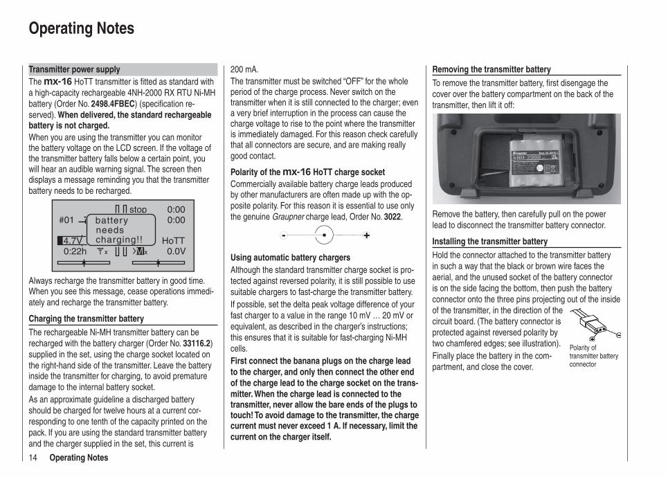
Transmitter power supplyThe mx-16 HoTT transmitter is fi tted as standard with a high-capacity rechargeable 4NH-2000 RX RTU Ni-MH battery (Order No. 2498.4FBEC) (specifi cation re-served). When delivered, the standard rechargeable battery is not charged.When you are using the transmitter you can monitor the battery voltage on the LCD screen. If the voltage of the transmitter battery falls below a certain point, you will hear an audible warning signal. The screen then displays a message reminding you that the transmitter battery needs to be recharged.
#01
0:22h
stop
0:000:00
0.0V4.7V HoTT
Mx
batteryneedscharging!!
x
Always recharge the transmitter battery in good time. When you see this message, cease operations immedi-ately and recharge the transmitter battery.
Charging the transmitter batteryThe rechargeable Ni-MH transmitter battery can be recharged with the battery charger (Order No. 33116.2) supplied in the set, using the charge socket located on the right-hand side of the transmitter. Leave the battery inside the transmitter for charging, to avoid premature damage to the internal battery socket.As an approximate guideline a discharged battery should be charged for twelve hours at a current cor-responding to one tenth of the capacity printed on the pack. If you are using the standard transmitter battery and the charger supplied in the set, this current is
200 mA. The transmitter must be switched “OFF” for the whole period of the charge process. Never switch on the transmitter when it is still connected to the charger; even a very brief interruption in the process can cause the charge voltage to rise to the point where the transmitter is immediately damaged. For this reason check carefully that all connectors are secure, and are making really good contact.
Polarity of the mx-16 HoTT charge socketCommercially available battery charge leads produced by other manufacturers are often made up with the op-posite polarity. For this reason it is essential to use only the genuine Graupner charge lead, Order No. 3022.
Using automatic battery chargersAlthough the standard transmitter charge socket is pro-tected against reversed polarity, it is still possible to use suitable chargers to fast-charge the transmitter battery.If possible, set the delta peak voltage difference of your fast charger to a value in the range 10 mV … 20 mV or equivalent, as described in the charger’s instructions; this ensures that it is suitable for fast-charging Ni-MH cells.First connect the banana plugs on the charge lead to the charger, and only then connect the other end of the charge lead to the charge socket on the trans-mitter. When the charge lead is connected to the transmitter, never allow the bare ends of the plugs to touch! To avoid damage to the transmitter, the charge current must never exceed 1 A. If necessary, limit the current on the charger itself.
Removing the transmitter batteryTo remove the transmitter battery, fi rst disengage the cover over the battery compartment on the back of the transmitter, then lift it off:
Remove the battery, then carefully pull on the power lead to disconnect the transmitter battery connector.
Installing the transmitter batteryHold the connector attached to the transmitter battery in such a way that the black or brown wire faces the aerial, and the unused socket of the battery connector is on the side facing the bottom, then push the battery connector onto the three pins projecting out of the inside of the transmitter, in the direction of the circuit board. (The battery connector is protected against reversed polarity by two chamfered edges; see illustration).Finally place the battery in the com-partment, and close the cover.
Polarity of transmitter battery connector
15Operating Notes
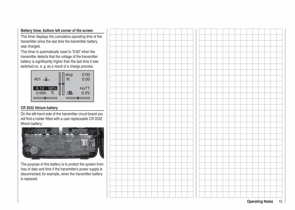
Battery timer, bottom left corner of the screenThis timer displays the cumulative operating time of the transmitter since the last time the transmitter battery was charged.This timer is automatically reset to “0:00” when the transmitter detects that the voltage of the transmitter battery is signifi cantly higher than the last time it was switched on, e. g. as a result of a charge process.
#01
0:00h
stop flt
0:000:00
0.0V6.1V 99% HoTT
Mx
CR 2032 lithium batteryOn the left-hand side of the transmitter circuit board you will fi nd a holder fi tted with a user-replaceable CR 2032 lithium battery:
The purpose of this battery is to protect the system from loss of date and time if the transmitter’s power supply is disconnected; for example, when the transmitter battery is replaced.

16 Operating Notes
Receiver power supplyA wide range of rechargeable four-cell and fi ve-cell NiMH batteries varying in capacity is available for use as the receiver power supply. If you are using digital servos we recommend that you use a fi ve-cell (6 V) pack of gener-ous capacity. If your model is fi tted with a mixture of digital and analogue servos, it is important to check the maximum permissible operating voltage of all the types.The PRX unit, Order No. 4136, provides a stabilised receiver power supply with a user-variable voltage from one or two receiver batteries; see Appendix.For reasons of safety battery boxes or dry cells should never be used.The voltage of the airborne power supply is displayed on the transmitter screen while the model is fl ying:
#01
2:22h
stop flt
0:000:00
5.5V51%5.2V
MHoTT
If the voltage falls below the pre-set warning threshold - 3.8 Volt as standard, but variable in the Telemetry menu; see page 126 - a visual and audible low-voltage warning is triggered.Nevertheless it is important to check the state of the batteries at regular intervals. Don’t put off charging the batteries until the warning signal is triggered.
Note:Please refer to the main Graupner FS catalogue or visit the Internet site at www.graupner.de for full details of batteries, chargers, measuring equipment and battery monitor units.
Charging the receiver batteryThe charge lead, Order No. 3021, can be connected directly to the NC receiver battery for charging. If the battery is installed in a model and you have installed one of the following switch harnesses: Order No. 3046, 3934 or 3934.1 or 3934.3, the battery can be charged via the separate charge socket, or the charge socket which is built into the switch. The switch on the switch harness must be left at the “OFF” position for charging.
Polarity of the receiver battery connector
General notes on battery chargingObserve the recommendations provided by the • charger manufacturer and the battery manufacturer at all times.Keep to the maximum permissible charge current • stated by the battery manufacturer.The maximum charge current for the transmitter • battery is 1.5 A. Limit the charge current to this value on the charger.If you wish to charge the transmitter battery at a • current higher than 1.5 A, you must fi rst remove the pack from the transmitter, otherwise you risk damag-ing the circuit board through overloading the conduc-tor tracks, and / or overheating the battery.Carry out a series of test charges to ensure that the • automatic charge termination circuit works correctly with your battery. This applies in particular if you wish to charge the standard Ni-MH battery using an automatic charger designed for Ni-Cd batteries.You may need to adjust the Delta Peak trigger volt-• age, if your charger provides this option.
Do not discharge the battery or carry out a battery • maintenance program via the integral charge socket. The charge socket is not suitable for this application.Always connect the charge lead to the charger fi rst, • and only then to the transmitter or receiver battery. Observing this rule eliminates the danger of acciden-tal short-circuits between the bare contacts of the charge lead plugs.If the battery becomes hot when on charge, it is time • to check the pack’s condition. Replace it if necessary, or reduce the charge current.Never leave batteries unsupervised when on • charge.
Environmental protection notes
Important information on the disposal of dry and rechargeable batteries:The German Battery Order places a legal requirement on every consumer to return all used and exhausted dry cells and rechargeable batteries. It is prohibited to dispose of these items in the ordinary domestic waste. At no charge to the user, old dry and rechargeable batteries can be surrendered at local authority collec-tion points, Graupner retail outlets, and any other shop where dry and rechargeable batteries of the same type are sold. You can also send batteries supplied by us to the following address - with adequate pre-paid postage - for disposal:Graupner GmbH & Co. KGService: Gebrauchte Batterien (Used batteries)Henriettenstr. 94 - 96D-73230 Kirchheim unter TeckYou can make an important contribution to environmen-tal protection in this way.
Operating Notes
17Operating Notes
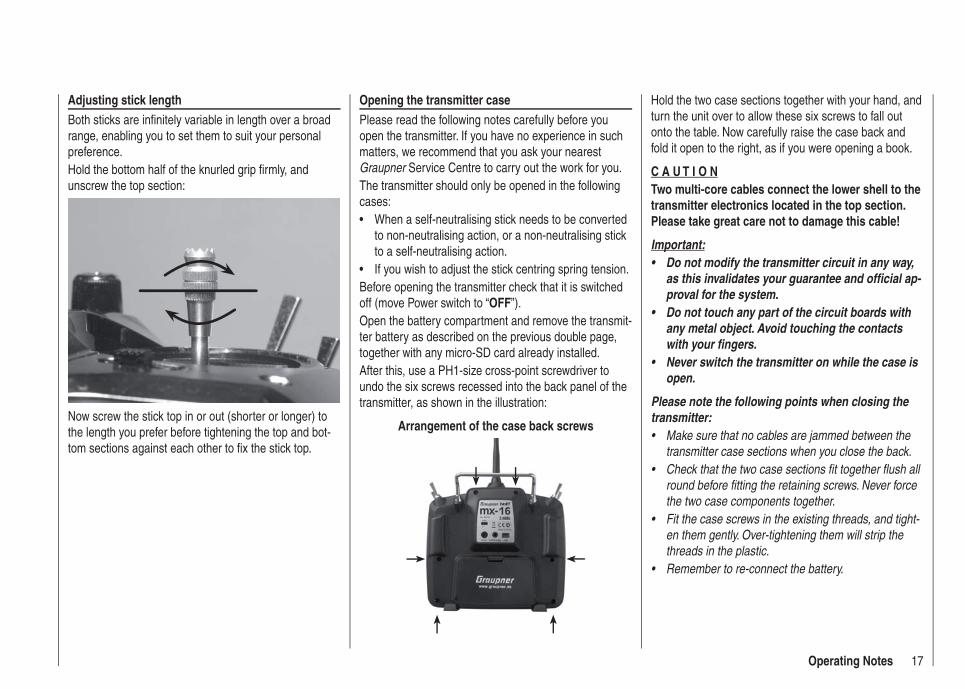
Adjusting stick lengthBoth sticks are infi nitely variable in length over a broad range, enabling you to set them to suit your personal preference.Hold the bottom half of the knurled grip fi rmly, and unscrew the top section:
Now screw the stick top in or out (shorter or longer) to the length you prefer before tightening the top and bot-tom sections against each other to fi x the stick top.
Opening the transmitter casePlease read the following notes carefully before you open the transmitter. If you have no experience in such matters, we recommend that you ask your nearest Graupner Service Centre to carry out the work for you.The transmitter should only be opened in the following cases:
When a self-neutralising stick needs to be converted • to non-neutralising action, or a non-neutralising stick to a self-neutralising action.If you wish to adjust the stick centring spring tension.•
Before opening the transmitter check that it is switched off (move Power switch to “OFF”).Open the battery compartment and remove the transmit-ter battery as described on the previous double page, together with any micro-SD card already installed.After this, use a PH1-size cross-point screwdriver to undo the six screws recessed into the back panel of the transmitter, as shown in the illustration:
Arrangement of the case back screws
Hold the two case sections together with your hand, and turn the unit over to allow these six screws to fall out onto the table. Now carefully raise the case back and fold it open to the right, as if you were opening a book.
C A U T I O NTwo multi-core cables connect the lower shell to the transmitter electronics located in the top section. Please take great care not to damage this cable!
Important:Do not modify the transmitter circuit in any way, • as this invalidates your guarantee and offi cial ap-proval for the system.Do not touch any part of the circuit boards with • any metal object. Avoid touching the contacts with your fi ngers.Never switch the transmitter on while the case is • open.
Please note the following points when closing the transmitter:
Make sure that no cables are jammed between the • transmitter case sections when you close the back.Check that the two case sections fit together flush all • round before fitting the retaining screws. Never force the two case components together.Fit the case screws in the existing threads, and tight-• en them gently. Over-tightening them will strip the threads in the plastic.Remember to re-connect the battery.•
18 Operating Notes
Operating Notes
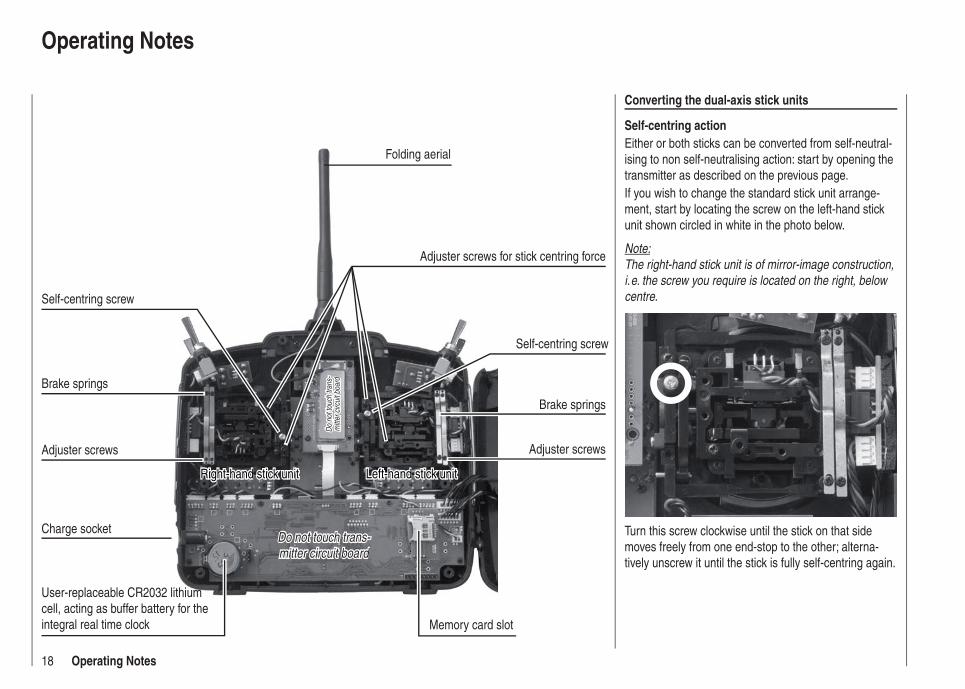
Converting the dual-axis stick units
Self-centring actionEither or both sticks can be converted from self-neutral-ising to non self-neutralising action: start by opening the transmitter as described on the previous page.If you wish to change the standard stick unit arrange-ment, start by locating the screw on the left-hand stick unit shown circled in white in the photo below.
Note:The right-hand stick unit is of mirror-image construction, i. e. the screw you require is located on the right, below centre.
Turn this screw clockwise until the stick on that side moves freely from one end-stop to the other; alterna-tively unscrew it until the stick is fully self-centring again.
Do not touch trans-Do not touch trans-mitter circuit boardmitter circuit board
Do
not t
ouch
tran
s-D
o no
t tou
ch tr
ans-
mitt
er c
ircui
t boa
rdm
itter
circ
uit b
oard
User-replaceable CR2032 lithium cell, acting as buffer battery for the integral real time clock Memory card slot
Charge socket
Left-hand stick unitLeft-hand stick unit
Brake springs
Adjuster screws
Brake springs
Adjuster screws
Folding aerial
Self-centring screw
Right-hand stick unitRight-hand stick unit
Self-centring screw
Adjuster screws for stick centring force
19Operating Notes
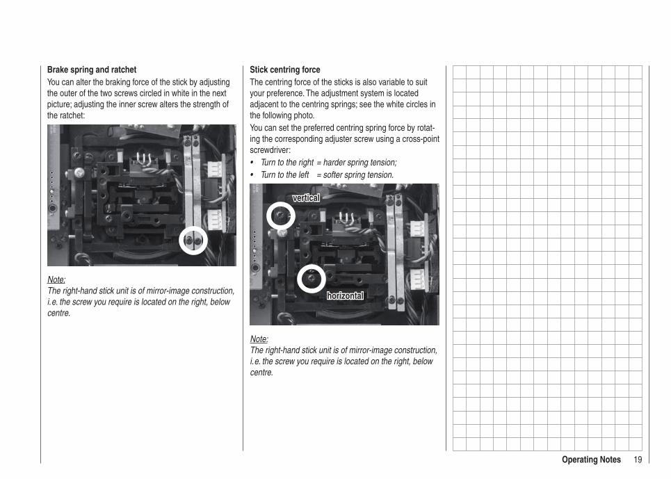
Stick centring forceThe centring force of the sticks is also variable to suit your preference. The adjustment system is located adjacent to the centring springs; see the white circles in the following photo.You can set the preferred centring spring force by rotat-ing the corresponding adjuster screw using a cross-point screwdriver:
Turn to the right = harder spring tension;• Turn to the left = softer spring tension.•
horizontalhorizontal
verticalvertical
Note:The right-hand stick unit is of mirror-image construction, i. e. the screw you require is located on the right, below centre.
Brake spring and ratchetYou can alter the braking force of the stick by adjusting the outer of the two screws circled in white in the next picture; adjusting the inner screw alters the strength of the ratchet:
Note:The right-hand stick unit is of mirror-image construction, i. e. the screw you require is located on the right, below centre.
20 Description of transmitter
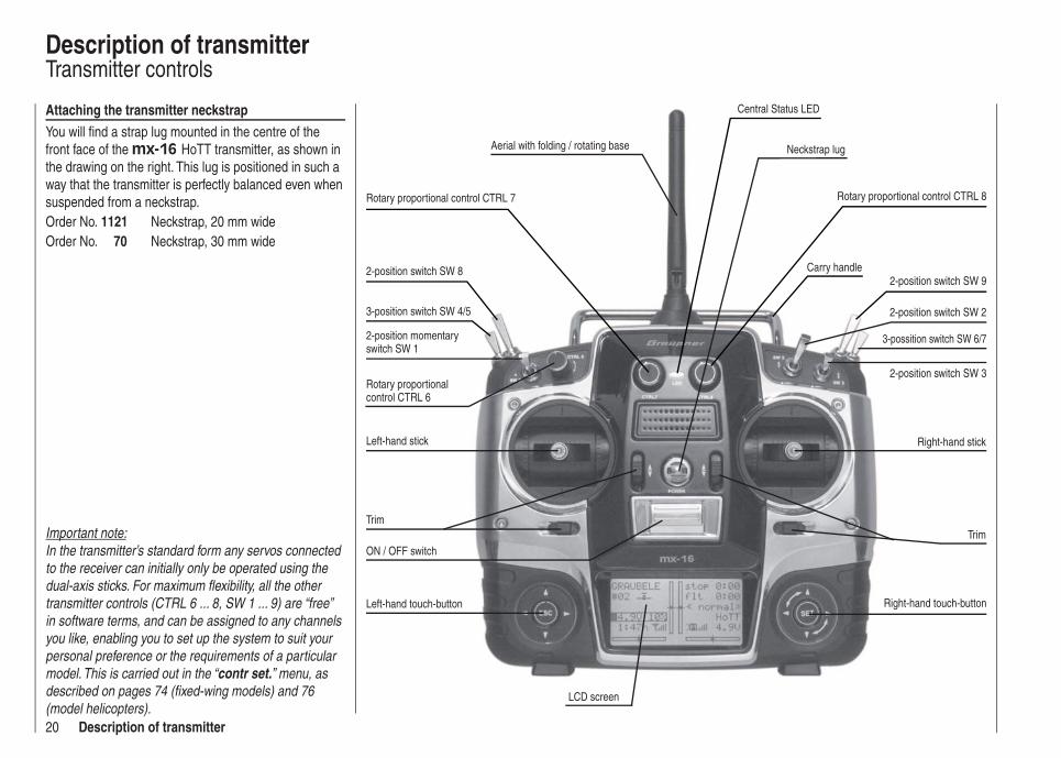
Description of transmitterTransmitter controls
Aerial with folding / rotating base
Rotary proportional control CTRL 7
3-position switch SW 4/5
2-position momentary switch SW 1
Rotary proportional control CTRL 6
Left-hand stick
Trim
ON / OFF switch
Left-hand touch-button
LCD screen
Right-hand touch-button
Trim
Right-hand stick
2-position switch SW 3
Carry handle
Neckstrap lug
Attaching the transmitter neckstrapYou will fi nd a strap lug mounted in the centre of the front face of the mx-16 HoTT transmitter, as shown in the drawing on the right. This lug is positioned in such a way that the transmitter is perfectly balanced even when suspended from a neckstrap.Order No. 1121 Neckstrap, 20 mm wideOrder No. 70 Neckstrap, 30 mm wide
3-possition switch SW 6/7
Rotary proportional control CTRL 8
Important note:In the transmitter’s standard form any servos connected to the receiver can initially only be operated using the dual-axis sticks. For maximum fl exibility, all the other transmitter controls (CTRL 6 ... 8, SW 1 ... 9) are “free” in software terms, and can be assigned to any channels you like, enabling you to set up the system to suit your personal preference or the requirements of a particular model. This is carried out in the “contr set.” menu, as described on pages 74 (fi xed-wing models) and 76 (model helicopters).
2-position switch SW 2
2-position switch SW 82-position switch SW 9
Central Status LED

21Description of transmitter
DSC socket for connecting fl ight simulators and for Teacher mode
Case screw Case screw
Case screw Case screw
Battery compartment cover
Case screw Case screw
Transmitter battery charge socket
Data socket for connecting Smart-Box, Order No. 33700
Five-pin mini-USB socket for connecting transmitter to a PC
Earphone / headphone socket
Headphone socketThe central socket at the bottom edge of the back panel name plate is intended for connecting a standard com-mercial earphone or headphones fi tted with a 3.5 mm barrel plug (not included in the set).Signals and voice messages associated with the Te-lemetry menu are generated via this socket, as are the transmitter’s audible signals. The default language for speech output is German. For more information on this please refer to “Voice messages” in the “HIDDEN MODE” section starting on page 26, and the “Teleme-try” section starting on page 130.The volume of the headphone output can be adjusted in the “Voice volume” line of the “General Settings” menu; see page 115.
mini-USB socketThis socket can be used to connect the transmitter to a PC running Windows XP, Vista or 7. The software required at the PC, including a suitable USB driver, can be found in the Download section for that product at www.graupner.de.Once you have installed the software required, you can update the transmitter via this connection as and when required, or simply set the correct date and time of day.
Data socketFor connecting the optional Smart-Box, Order No. 33700.For more details about the Smart-Box please refer to the main Graupner FS catalogue, or refer to that product on the Internet at www.graupner.de.
22 Description of transmitter
PUPIL#11
0:01h
stop flt
DSC
0:000:00
6.0V 99% HoTT
The transmitter is now ready for use.In contrast, when the mx-16 HoTT is used in Teacher mode, the transmitter must be switched on before the appropriate cable is plugged in.3. Connect the other end of the connecting lead to the appropriate apparatus, taking into account the operating instructions supplied with that device.Important:Ensure that all connectors are fi rmly seated in their sockets.
Note regarding fl ight simulators:The range of fl ight simulators available commercially is now very wide, and you may fi nd that it is necessary to swap over certain contacts at the barrel connector or the DSC module. This work must be carried out by a Graupner Service Centre.
DSCDirect Servo Control
The original function of this socket was for “Direct Servo Control”, and that’s why the abbreviation is still in use. However, for technical reasons “direct servo control” is no longer possible with the HoTT system using a diag-nosis lead.The mx-16 HoTT transmitter’s standard two-pole DSC socket is now used as a Trainer (buddy box) socket (Teacher or Pupil), and as an interface for fl ight simula-tors.
For the DSC connection to work you must check the following:
Carry out any adjustments required in the appropri-1. ate menus:See page 134 for information on setting up the mx-16 HoTT transmitter to work as part of a Trainer sys-tem.ALWAYS2. leave the transmitter’s On / Off switch in the “OFF” position when using a fl ight simulator, and when using the mx-16 HoTT transmitter as a Pu-pil unit in a Trainer system, for only in this position is the RF section of the transmitter module switched off (no RF signal) even when the DSC lead is plugged in. At the same time the transmitter’s current drain is reduced slightly.The central Status LED should now glow a con-stant red, and the abbreviation “DSC” appears in the transmitter’s base display on the left, below the mod-el number. At the same time the display of telemetry symbols is suppressed:
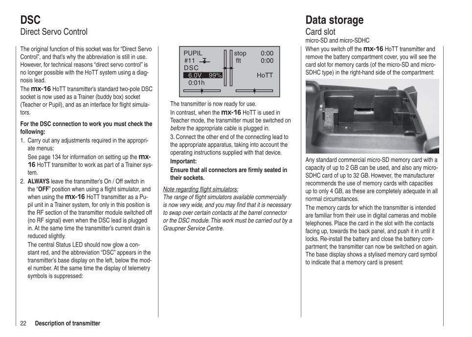
Data storageCard slotmicro-SD and micro-SDHCWhen you switch off the mx-16 HoTT transmitter and remove the battery compartment cover, you will see the card slot for memory cards (of the micro-SD and micro-SDHC type) in the right-hand side of the compartment:
Any standard commercial micro-SD memory card with a capacity of up to 2 GB can be used, and also any micro-SDHC card of up to 32 GB. However, the manufacturer recommends the use of memory cards with capacities up to only 4 GB, as these are completely adequate in all normal circumstances.The memory cards for which the transmitter is intended are familiar from their use in digital cameras and mobile telephones. Place the card in the slot with the contacts facing up, towards the back panel, and push it in until it locks. Re-install the battery and close the battery com-partment; the transmitter can now be switched on again. The base display shows a stylised memory card symbol to indicate that a memory card is present:
23Description of transmitter
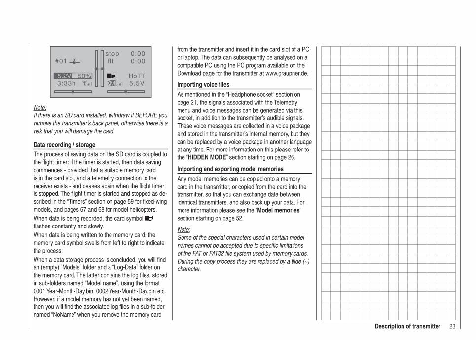
#01
3:33h
stop flt
0:000:00
5.5V50%5.2V HoTT
M
Note:If there is an SD card installed, withdraw it BEFORE you remove the transmitter’s back panel, otherwise there is a risk that you will damage the card.
Data recording / storageThe process of saving data on the SD card is coupled to the fl ight timer: if the timer is started, then data saving commences - provided that a suitable memory card is in the card slot, and a telemetry connection to the receiver exists - and ceases again when the fl ight timer is stopped. The fl ight timer is started and stopped as de-scribed in the “Timers” section on page 59 for fi xed-wing models, and pages 67 and 68 for model helicopters.When data is being recorded, the card symbol fl ashes constantly and slowly.When data is being written to the memory card, the memory card symbol swells from left to right to indicate the process.When a data storage process is concluded, you will fi nd an (empty) “Models” folder and a “Log-Data” folder on the memory card. The latter contains the log fi les, stored in sub-folders named “Model name”, using the format 0001 Year-Month-Day.bin, 0002 Year-Month-Day.bin etc. However, if a model memory has not yet been named, then you will fi nd the associated log fi les in a sub-folder named “NoName” when you remove the memory card
from the transmitter and insert it in the card slot of a PC or laptop. The data can subsequently be analysed on a compatible PC using the PC program available on the Download page for the transmitter at www.graupner.de.
Importing voice fi lesAs mentioned in the “Headphone socket” section on page 21, the signals associated with the Telemetry menu and voice messages can be generated via this socket, in addition to the transmitter’s audible signals. These voice messages are collected in a voice package and stored in the transmitter’s internal memory, but they can be replaced by a voice package in another language at any time. For more information on this please refer to the “HIDDEN MODE” section starting on page 26.
Importing and exporting model memoriesAny model memories can be copied onto a memory card in the transmitter, or copied from the card into the transmitter, so that you can exchange data between identical transmitters, and also back up your data. For more information please see the “Model memories” section starting on page 52.
Note:Some of the special characters used in certain model names cannot be accepted due to specifi c limitations of the FAT or FAT32 fi le system used by memory cards. During the copy process they are replaced by a tilde (~) character.

24 Description of transmitter - screen and keypad
Signal strength indicator Battery operating time since last battery charge, in hr:min
Screen and keypad
Flight timer in min:sec (count-up / count-down)
Stopwatch in min:sec (count-up / count-down)
Flight phase nameSwitching between fl ight phases using switch
Receiver power supply voltage
Right-hand touch-key
leaf through / alter valuesSET Select / Confi rm
Model name
Model memory 1 … 20
Battery voltage and charge state in %(If voltage falls below a particular level, a warning display appears - see pictures on right-hand page; at the same time a warning signal is emitted.)
Visual display of the trim lever positions; alternatively - if rota-ry controls CTRL 7 … 9 are operated - display of the current settings of these two controls
Model type display(fi xed-wing / helicopter)
Left-hand touch-key leaf through pressed briefl y together: switches to Servo display menu
ESC = interrupt / backESC touched for about three
seconds; Switches to the Telemetry menu, and back to the base display
See page 28 for possible warnings
Simultaneous brief press of or = CLEAR
25Description of transmitter - screen and keypad
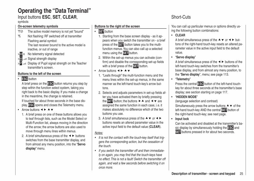
Operating the “Data Terminal”Input buttons ESC, SET, CLEAR, symbolsOn-screen telemetry symbols
The active model memory is not yet “bound” Not fl ashing: RF switched off at transmitter
Flashing aerial symbol:The last receiver bound to the active model is inactive, or out of range
>M x No telemetry signal detected>M Signal strength display>P Display of Pupil signal strength on the Teacher
transmitter’s screen.
Buttons to the left of the screenESC• button A brief press on the ESC button returns you step by step within the function select system, taking you right back to the basic display. If you make a change in the meantime, the change is retained.If touched for about three seconds in the base dis-play, ESC opens and closes the Telemetry menu.Arrow buttons •
A brief press on one of these buttons allows you 1. to leaf through lists, such as the Model Select or Multi-Function list, always moving in the direction of the arrow; the arrow buttons are also used to move through menu lines within menus.A brief simultaneous press of the 2. buttons switches from the base transmitter display, and from almost any menu position, into the “Servo display” menu.
Buttons to the right of the screenSET• button
Starting from the base screen display - as it ap-1. pears when you switch the transmitter on - a brief press of the SET button takes you to the multi-function menus. You can also call up a selected menu using the SET button.Within the set-up menus you can activate (con-2. fi rm) and disable the corresponding set-up fi elds with a brief press of the SET button.
Arrow buttons • 1. “Leafs through” the multi-function menu and the
menu lines within the set-up menus, in the same manner as the left-hand touch-key’s arrow but-tons.
2. Selects and adjusts parameters in set-up fi elds af-ter you have activated them by briefl y pressing the SET button; the buttons and are assigned the same function in each case, i. e. it makes absolutely no difference which of the two buttons you use.
3. A brief simultaneous press of the or buttons resets an altered parameter value in the active input fi eld to the default value (CLEAR).
Notes:It is not the contact with the touch-key itself that trig-• gers the corresponding action, but the cessation of the touch.If you switch the transmitter off and then immediate-• ly on again, you may fi nd that the touch-keys have no effect. This is not a fault! Switch the transmitter off again, and wait a few seconds before switching it on once more.
Short-Cuts
You can call up particular menus or options directly us-ing the following button combinations:
CLEAR• A brief simultaneous press of the or but-tons of the right-hand touch-key resets an altered pa-rameter value in the active input fi eld to the default value.“• Servo display”A brief simultaneous press of the buttons of the left-hand touch-key switches from the transmitter’s base display, and from almost any menu position, to the “Servo display”, menu; see page 113.“• Telemetry”Press the central ESC button of the left-hand touch-key for about three seconds at the transmitter’s base display; see section starting on page 117.“• HIDDEN MODE” (language selection and contrast)Simultaneously press the arrow buttons of the left-hand touch-key AND the central SET button of the right-hand touch-key; see next page.Input lock• Can be activated and disabled at the transmitter’s ba-sic display by simultaneously holding the ESC and SET buttons pressed in for about two seconds.
26 Description of transmitter
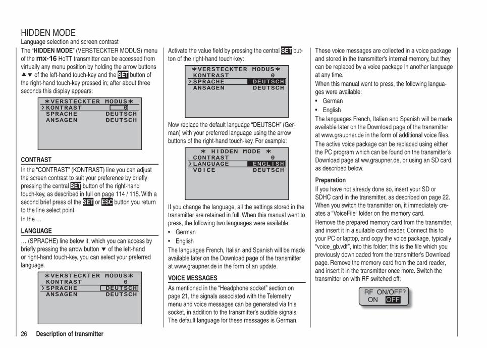
The “HIDDEN MODE” (VERSTECKTER MODUS) menu of the mx-16 HoTT transmitter can be accessed from virtually any menu position by holding the arrow buttons
of the left-hand touch-key and the SET button of the right-hand touch-key pressed in; after about three seconds this display appears:
VERSTECKTER MODUSKONTRASTSPRACHE
0DEUTSCH
ANSAGEN DEUTSCH
CONTRASTIn the “CONTRAST” (KONTRAST) line you can adjust the screen contrast to suit your preference by briefl y pressing the central SET button of the right-hand touch-key, as described in full on page 114 / 115. With a second brief press of the SET or ESC button you return to the line select point.In the …
LANGUAGE … (SPRACHE) line below it, which you can access by briefl y pressing the arrow button of the left-hand or right-hand touch-key, you can select your preferred language.
VERSTECKTER MODUSKONTRASTSPRACHE
0DEUTSCH
ANSAGEN DEUTSCH
HIDDEN MODELanguage selection and screen contrast
Activate the value fi eld by pressing the central SET but-ton of the right-hand touch-key:
VERSTECKTER MODUSKONTRASTSPRACHE
0
ANSAGEN DEUTSCHDEUTSCH
Now replace the default language “DEUTSCH” (Ger-man) with your preferred language using the arrow buttons of the right-hand touch-key. For example:
HIDDEN MODE CONTRASTLANGUAGE
0
VOICE DEUTSCHENGLISH
If you change the language, all the settings stored in the transmitter are retained in full. When this manual went to press, the following two languages were available:
German• English•
The languages French, Italian and Spanish will be made available later on the Download page of the transmitter at www.graupner.de in the form of an update.
VOICE MESSAGESAs mentioned in the “Headphone socket” section on page 21, the signals associated with the Telemetry menu and voice messages can be generated via this socket, in addition to the transmitter’s audible signals. The default language for these messages is German.
These voice messages are collected in a voice package and stored in the transmitter’s internal memory, but they can be replaced by a voice package in another language at any time.When this manual went to press, the following langua-ges were available:
German• English•
The languages French, Italian and Spanish will be made available later on the Download page of the transmitter at www.graupner.de in the form of additional voice fi les.The active voice package can be replaced using either the PC program which can be found on the transmitter’s Download page at ww.graupner.de, or using an SD card, as described below.
PreparationIf you have not already done so, insert your SD or SDHC card in the transmitter, as described on page 22. When you switch the transmitter on, it immediately cre-ates a “VoiceFile” folder on the memory card.Remove the prepared memory card from the transmitter, and insert it in a suitable card reader. Connect this to your PC or laptop, and copy the voice package, typically “voice_gb.vdf”, into this folder; this is the fi le which you previously downloaded from the transmitter’s Download page. Remove the memory card from the card reader, and insert it in the transmitter once more. Switch the transmitter on with RF switched off:
RF ON/OFF?ON OFF
27Description of transmitter
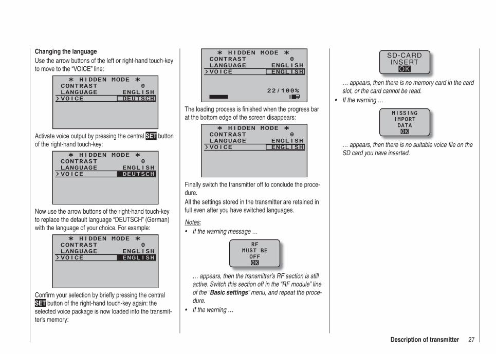
Changing the languageUse the arrow buttons of the left or right-hand touch-key to move to the “VOICE” line:
HIDDEN MODE CONTRASTLANGUAGE
0ENGLISH
VOICE DEUTSCH
Activate voice output by pressing the central SET button of the right-hand touch-key:
HIDDEN MODE CONTRASTLANGUAGE
0ENGLISH
VOICE DEUTSCH
Now use the arrow buttons of the right-hand touch-key to replace the default language “DEUTSCH” (German) with the language of your choice. For example:
HIDDEN MODE CONTRASTLANGUAGE
0ENGLISH
VOICE ENGLISH
Confi rm your selection by briefl y pressing the central SET button of the right-hand touch-key again: the selected voice package is now loaded into the transmit-ter’s memory:
HIDDEN MODE CONTRASTLANGUAGE
0ENGLISH
VOICE ENGLISH
22/100%I
The loading process is fi nished when the progress bar at the bottom edge of the screen disappears:
HIDDEN MODE CONTRASTLANGUAGE
0ENGLISH
VOICE ENGLISH
Finally switch the transmitter off to conclude the proce-dure.All the settings stored in the transmitter are retained in full even after you have switched languages.
Notes:If the warning message …•
RFMUST BE
OFFOK
… appears, then the transmitter’s RF section is still active. Switch this section off in the “RF module” line of the “Basic settings” menu, and repeat the proce-dure.If the warning …•
SD-CARDINSERT
OK
… appears, then there is no memory card in the card slot, or the card cannot be read.If the warning …•
MISSINGIMPORTDATAOK
… appears, then there is no suitable voice fi le on the SD card you have inserted.
28 Description of transmitter
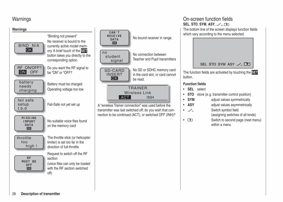
Warnings
BIND N/AOK
“Binding not present”No receiver is bound to the currently active model mem-ory. A brief touch of the SET button takes you directly to the corresponding option.
RF ON/OFF?OFFON
Do you want the RF signal to be “ON” or “OFF?
batteryneedscharging
Battery must be chargedOperating voltage too low
fai l safesetupt.b.d
Fail-Safe not yet set up
MISSINGIMPORTDATAOK
No suitable voice fi les found on the memory card
thrott letoo
high !
The throttle stick (or helicopter limiter) is set too far in the direction of full-throttle
RFMUST BE
OFFOK
Request to switch off the RF section (voice fi les can only be loaded with the RF section switched off)
Warnings
The bottom line of the screen displays function fi elds which vary according to the menu selected.
SEL STO SYM ASY
The function fi elds are activated by touching the SET button.
Function fi eldsSEL• selectSTO• store (e. g. transmitter control position) SYM• adjust values symmetricallyASY• adjust values asymmetrically
• Switch symbol fi eld (assigning switches of all kinds)
• Switch to second page (next menu) within a menu
On-screen function fi eldsSEL, STO, SYM, ASY, ,
CAN‘TRECEIVEDATAOK
No bound receiver in range.
nostudent
signal
No connection between Teacher and Pupil transmitters
SD-CARDINSERT
OK
No SD or SDHC memory card in the card slot, or card cannot be read.
TRAINERWireless Link
INHACT
A “wireless Trainer connection” was used before the transmitter was last switched off; do you wish that con-nection to be continued (ACT), or switched OFF (INH)?

29Description of transmitter
As soon as you operate one of the two rotary controls CTRL 7 + 8 on the centre console, a small symbol ap-pears to the right of the two vertical position indicators:
At the same time the position display of the two central vertical bars switches for the duration of the actuation from the display of the current trim position to the cur-rent position of the rotary controls CTRL 7 + 8.As you would expect, the left-hand bar represents the position of the left-hand rotary control CTRL 7, and the right-hand bar refl ects the position of CTRL 8 (however, both horizontal bars continue to show the current posi-tion of the corresponding transmitter stick trim levers):
#01
3:33h
stop flt
0:000:00
50%5.2V HoTTM
About two seconds after you cease operating one of the two rotary controls, the screen reverts to a display of the current position of the four trim levers for the two dual-axis stick units.
Position displayRotary proportional controls CTRL 7 and 8
To prevent programming errors, it is possible to lock the touch-keys, and with them access to all the set-up options, from the base display of the mx-16 HoTT transmitter by touching the ESC and SET buttons for about two seconds. This is indicated by an inverted key symbol at the centre point of the trim bars:
#01
3:33h
stop flt
0:000:00
5.5V50%5.2V HoTT
M
The lock is immediately active, but the control system remains ready for use.Touching the ESC and SET buttons again for about two seconds disengages the lock: the next time you switch the transmitter on, the lock is also disengaged.
Input lock
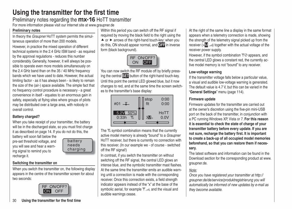
30 Using the transmitter for the fi rst time
Preliminary notesIn theory the Graupner HoTT system permits the simul-taneous operation of more than 200 models.However, in practice the mixed operation of different technical systems in the 2.4 GHz ISM band - as required by the approval regulations - reduces this number considerably. Generally, however, it will always be pos-sible to operate even more models simultaneously on the 2.4 GHz band than on the 35 / 40 MHz frequency bands which we have used to date. However, the actual limiting factor - as it has always been - is likely to remain the size of the (air-) space available. The simple fact that no frequency control procedure is necessary - a great convenience in itself - equates to an enormous gain in safety, especially at fl ying sites where groups of pilots may be distributed over a large area, with nobody in overall control.
Battery charged?When you take receipt of your transmitter, the battery will be in the discharged state, so you must fi rst charge it as described on page 14. If you do not do this, the battery will soon fall below the pre-set threshold voltage, and you will see and hear a warn-ing signal to remind you to recharge it.
Switching the transmitter onWhen you switch the transmitter on, the following display appears in the centre of the transmitter screen for about two seconds:
RF ON/OFF?OFFON
Within this period you can switch off the RF signal if required by moving the black fi eld to the right using the
or arrows of the right-hand touch-key; when you do this, ON should appear normal, and OFF in inverse form (black background).
RF ON/OFF?ON OFF
You can now switch the RF module off by briefl y press-ing the central SET button of the right-hand touch-key.Until this point the central LED glowed blue, but it now changes to red, and at the same time the screen switch-es to the transmitter’s base display:
#01
0:33h
stop flt
0:000:00
0.0V50%5.2V HoTT
M
The symbol combination means that the currently active model memory is already “bound” to a Graupner HoTT receiver, but there is currently no connection with this receiver. (In our example we - of course - switched off the RF signal!)In contrast, if you switch the transmitter on without switching off the RF signal, the central LED glows an intense blue, and the symbolic transmitter mast fl ashes. At the same time the transmitter emits an audible warn-ing until a connection is made with the corresponding receiver. Once this connection exists, a fi eld strength indicator appears instead of the “x” at the base of the symbolic aerial, for example , and the visual and audible warnings cease.
batteryneedscharging
Using the transmitter for the fi rst timePreliminary notes regarding the mx-16 HoTT transmitterFor more information please visit our Internet site at www.graupner.de
At the right of the same line a display in the same format appears when a telemetry connection is made, showing the strength of the telemetry signal picked up from the receiver (>M ) together with the actual voltage of the receiver power supply.However, if the symbol combination appears, and the central LED glows a constant red, the currently ac-tive model memory is not “bound” to any receiver.
Low-voltage warningIf the transmitter voltage falls below a particular value, a visual and audible low-voltage warning is generated. The default value is 4.7 V, but this can be varied in the “General Settings” menu (page 114).
Firmware updateFirmware updates for the transmitter are carried out at the owner’s discretion using the fi ve-pin mini-USB port on the back of the transmitter, in conjunction with a PC running Windows XP, Vista or 7. For this reason it is essential to check the state of charge of your transmitter battery before every update. If you are not sure, recharge the battery fi rst. It is important to create a back-up of all occupied model memories beforehand, so that you can restore them if neces-sary.The latest software and information can be found in the Download section for the corresponding product at www.graupner.de.
Note:Once you have registered your transmitter at http://graupner.de/de/service/produktregistrierung you will automatically be informed of new updates by e-mail as they become available.
31Using the transmitter for the fi rst time
Any standard commercial USB lead with a fi ve-pin mini-USB plug at the transmitter end can be used to connect the transmitter to the PC; a typical example is that sup-plied with the interface, Order No. 7168.6.
Important notes:The transmitter included in the set is prepared at • the factory with the correct settings for most Eu-ropean countries (except France).If you wish to operate the RC system in France, you MUST fi rst set the Country setting on the transmitter to “FRANCE” mode; see page 115. IT IS PROHIBITED to use the system IN FRANCE using the Universal / EUROPE mode!You can operate up to eight servos using the • mx-16 HoTT transmitter and the receiver sup-plied in the set, which is already bound to the transmitter.However, in the interest of maximum possi-ble fl exibility, control channels 5 … 8 are not as-signed to transmitter controls by default; this also helps to eliminate the danger of inadvertent-ly using them incorrectly. For the same reason virtually all the mixers are inactive by default. For more details of this please refer to page 74 (fi xed-wing model) or 76 (helicopter).The basic procedure for programming a new • model memory can be found on page 48, and in the programming examples starting on page 144.When switching on, binding or setting up the ra-• dio control system, please ensure at all times that the transmitter aerial is an adequate distance from the receiver aerials. If the transmitter aeri-al is too close to the receiver aerials, the receiver
will be swamped, and the red LED on the receiv-er will begin to glow. At the same time the down-link channel will stop working. As a result the fi eld strength bars on the transmitter screen are replaced by “x”, and the receiver battery voltage is displayed as 0.0 V. At the same time the radio control system switches to Fail-Safe mode.If this should happen, simply increase the dis-tance between transmitter and receiver until the displays revert to “normal”.
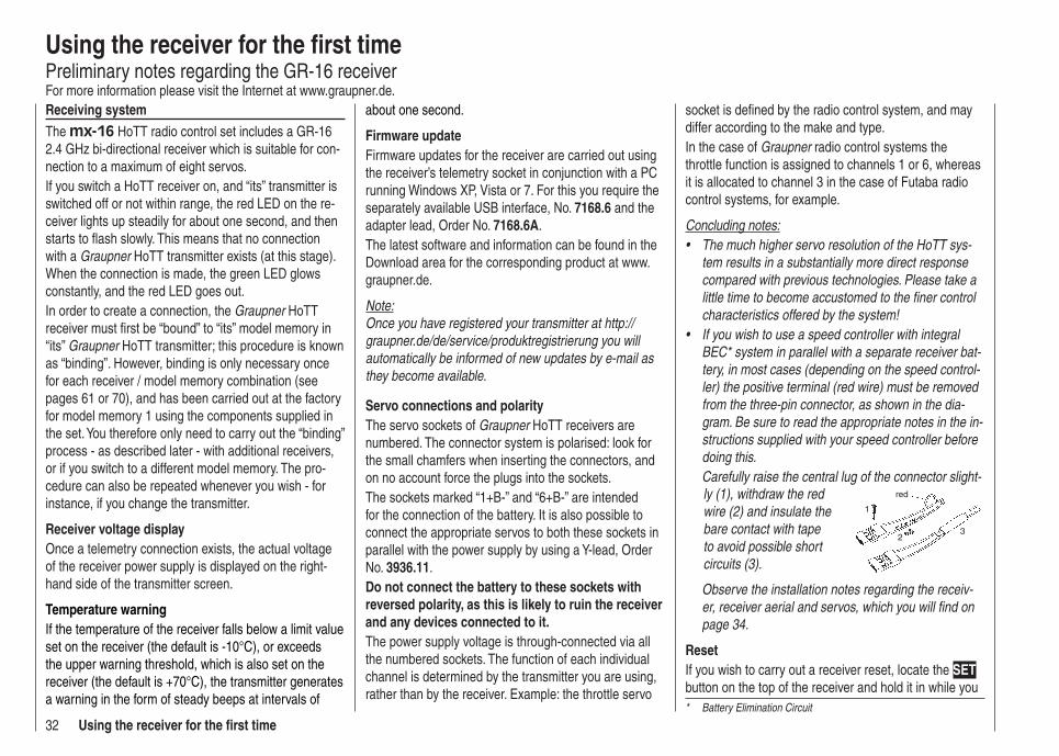
32 Using the receiver for the fi rst time
Using the receiver for the fi rst timePreliminary notes regarding the GR-16 receiverFor more information please visit the Internet at www.graupner.de.Receiving systemThe mx-16 HoTT radio control set includes a GR-16 2.4 GHz bi-directional receiver which is suitable for con-nection to a maximum of eight servos.If you switch a HoTT receiver on, and “its” transmitter is switched off or not within range, the red LED on the re-ceiver lights up steadily for about one second, and then starts to fl ash slowly. This means that no connection with a Graupner HoTT transmitter exists (at this stage). When the connection is made, the green LED glows constantly, and the red LED goes out.In order to create a connection, the Graupner HoTT receiver must fi rst be “bound” to “its” model memory in “its” Graupner HoTT transmitter; this procedure is known as “binding”. However, binding is only necessary once for each receiver / model memory combination (see pages 61 or 70), and has been carried out at the factory for model memory 1 using the components supplied in the set. You therefore only need to carry out the “binding” process - as described later - with additional receivers, or if you switch to a different model memory. The pro-cedure can also be repeated whenever you wish - for instance, if you change the transmitter.
Receiver voltage displayOnce a telemetry connection exists, the actual voltage of the receiver power supply is displayed on the right-hand side of the transmitter screen.
Temperature warningIf the temperature of the receiver falls below a limit value set on the receiver (the default is -10°C), or exceeds the upper warning threshold, which is also set on the receiver (the default is +70°C), the transmitter generates a warning in the form of steady beeps at intervals of
about one second.
Firmware updateFirmware updates for the receiver are carried out using the receiver’s telemetry socket in conjunction with a PC running Windows XP, Vista or 7. For this you require the separately available USB interface, No. 7168.6 and the adapter lead, Order No. 7168.6A.The latest software and information can be found in the Download area for the corresponding product at www.graupner.de.
Note:Once you have registered your transmitter at http://graupner.de/de/service/produktregistrierung you will automatically be informed of new updates by e-mail as they become available.
Servo connections and polarityThe servo sockets of Graupner HoTT receivers are numbered. The connector system is polarised: look for the small chamfers when inserting the connectors, and on no account force the plugs into the sockets.The sockets marked “1+B-” and “6+B-” are intended for the connection of the battery. It is also possible to connect the appropriate servos to both these sockets in parallel with the power supply by using a Y-lead, Order No. 3936.11.Do not connect the battery to these sockets with reversed polarity, as this is likely to ruin the receiver and any devices connected to it.The power supply voltage is through-connected via all the numbered sockets. The function of each individual channel is determined by the transmitter you are using, rather than by the receiver. Example: the throttle servo
socket is defi ned by the radio control system, and may differ according to the make and type.In the case of Graupner radio control systems the throttle function is assigned to channels 1 or 6, whereas it is allocated to channel 3 in the case of Futaba radio control systems, for example.
Concluding notes:The much higher servo resolution of the HoTT sys-• tem results in a substantially more direct response compared with previous technologies. Please take a little time to become accustomed to the fi ner control characteristics offered by the system!If you wish to use a speed controller with integral • BEC* system in parallel with a separate receiver bat-tery, in most cases (depending on the speed control-ler) the positive terminal (red wire) must be removed from the three-pin connector, as shown in the dia-gram. Be sure to read the appropriate notes in the in-structions supplied with your speed controller before doing this.Carefully raise the central lug of the connector slight-ly (1), withdraw the red wire (2) and insulate the bare contact with tape to avoid possible short circuits (3).
red
1
23
Observe the installation notes regarding the receiv-er, receiver aerial and servos, which you will fi nd on page 34.
ResetIf you wish to carry out a receiver reset, locate the SET button on the top of the receiver and hold it in while you * Battery Elimination Circuit
33Using the receiver for the fi rst time
connect its power supply; release the button again.If the reset is carried out with the transmitter switched off, or if the receiver is not already bound, the receiver LED fl ashes red slowly after about two or three sec-onds; at this stage it is immediately possible to initiate a binding process at the transmitter. If the reset is carried out with an already bound receiver, if the transmitter is switched on, and if the associated model memory is ac-tive, then the LED lights up green after a short interval to indicate that your transmitter / receiving system is ready for use once more.
Please note the following: Resetting the receiver resets ALL the settings stored in the receiver to the default settings, with the exception of the binding information! If you carry out a reset by mistake, this means that you will have to restore all the receiver settings entered using the Telemetry menu.On the other hand, a deliberate RESET is particu-larly useful if you wish to “re-house” a receiver in a different model, as it represents an easy method of avoiding the transference of unsuitable settings.
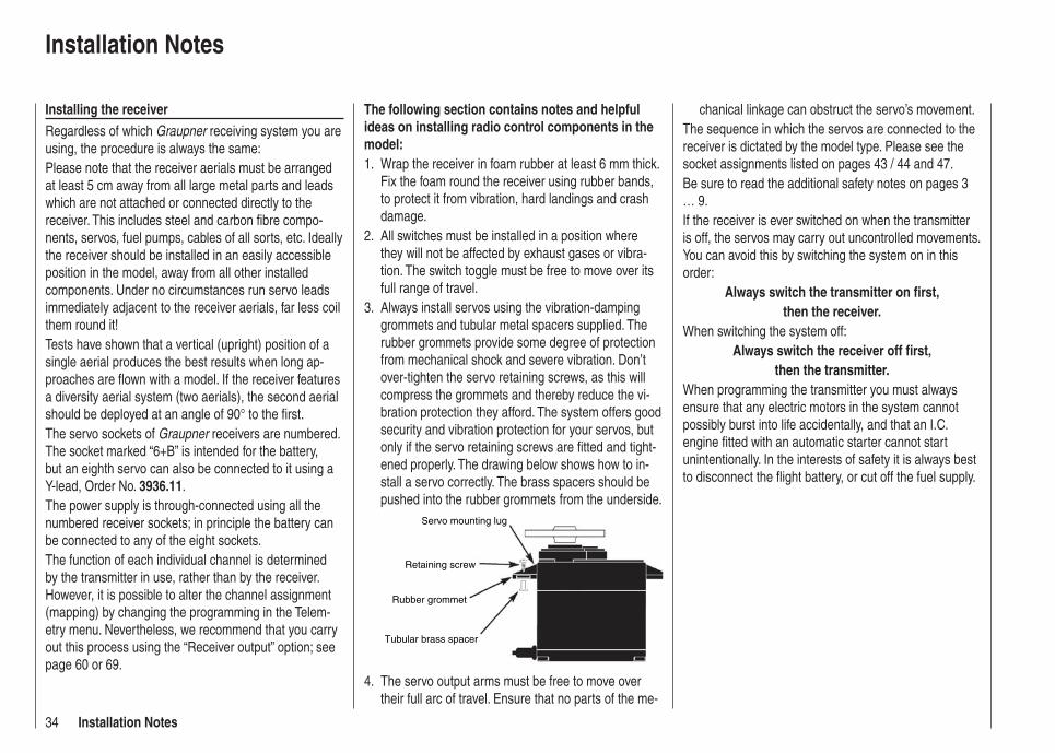
34 Installation Notes
chanical linkage can obstruct the servo’s movement.The sequence in which the servos are connected to the receiver is dictated by the model type. Please see the socket assignments listed on pages 43 / 44 and 47.Be sure to read the additional safety notes on pages 3 … 9.If the receiver is ever switched on when the transmitter is off, the servos may carry out uncontrolled movements. You can avoid this by switching the system on in this order:
Always switch the transmitter on fi rst,then the receiver.
When switching the system off:Always switch the receiver off fi rst,
then the transmitter.When programming the transmitter you must always ensure that any electric motors in the system cannot possibly burst into life accidentally, and that an I.C. engine fi tted with an automatic starter cannot start unintentionally. In the interests of safety it is always best to disconnect the fl ight battery, or cut off the fuel supply.
The following section contains notes and helpful ideas on installing radio control components in the model:
Wrap the receiver in foam rubber at least 6 mm thick. 1. Fix the foam round the receiver using rubber bands, to protect it from vibration, hard landings and crash damage.All switches must be installed in a position where 2. they will not be affected by exhaust gases or vibra-tion. The switch toggle must be free to move over its full range of travel.Always install servos using the vibration-damping 3. grommets and tubular metal spacers supplied. The rubber grommets provide some degree of protection from mechanical shock and severe vibration. Don’t over-tighten the servo retaining screws, as this will compress the grommets and thereby reduce the vi-bration protection they afford. The system offers good security and vibration protection for your servos, but only if the servo retaining screws are fi tted and tight-ened properly. The drawing below shows how to in-stall a servo correctly. The brass spacers should be pushed into the rubber grommets from the underside.
Servo mounting lug
Retaining screw
Rubber grommet
Tubular brass spacer
The servo output arms must be free to move over 4. their full arc of travel. Ensure that no parts of the me-
Installation Notes
Installing the receiverRegardless of which Graupner receiving system you are using, the procedure is always the same:Please note that the receiver aerials must be arranged at least 5 cm away from all large metal parts and leads which are not attached or connected directly to the receiver. This includes steel and carbon fi bre compo-nents, servos, fuel pumps, cables of all sorts, etc. Ideally the receiver should be installed in an easily accessible position in the model, away from all other installed components. Under no circumstances run servo leads immediately adjacent to the receiver aerials, far less coil them round it!Tests have shown that a vertical (upright) position of a single aerial produces the best results when long ap-proaches are fl own with a model. If the receiver features a diversity aerial system (two aerials), the second aerial should be deployed at an angle of 90° to the fi rst.The servo sockets of Graupner receivers are numbered. The socket marked “6+B” is intended for the battery, but an eighth servo can also be connected to it using a Y-lead, Order No. 3936.11.The power supply is through-connected using all the numbered receiver sockets; in principle the battery can be connected to any of the eight sockets.The function of each individual channel is determined by the transmitter in use, rather than by the receiver. However, it is possible to alter the channel assignment (mapping) by changing the programming in the Telem-etry menu. Nevertheless, we recommend that you carry out this process using the “Receiver output” option; see page 60 or 69.
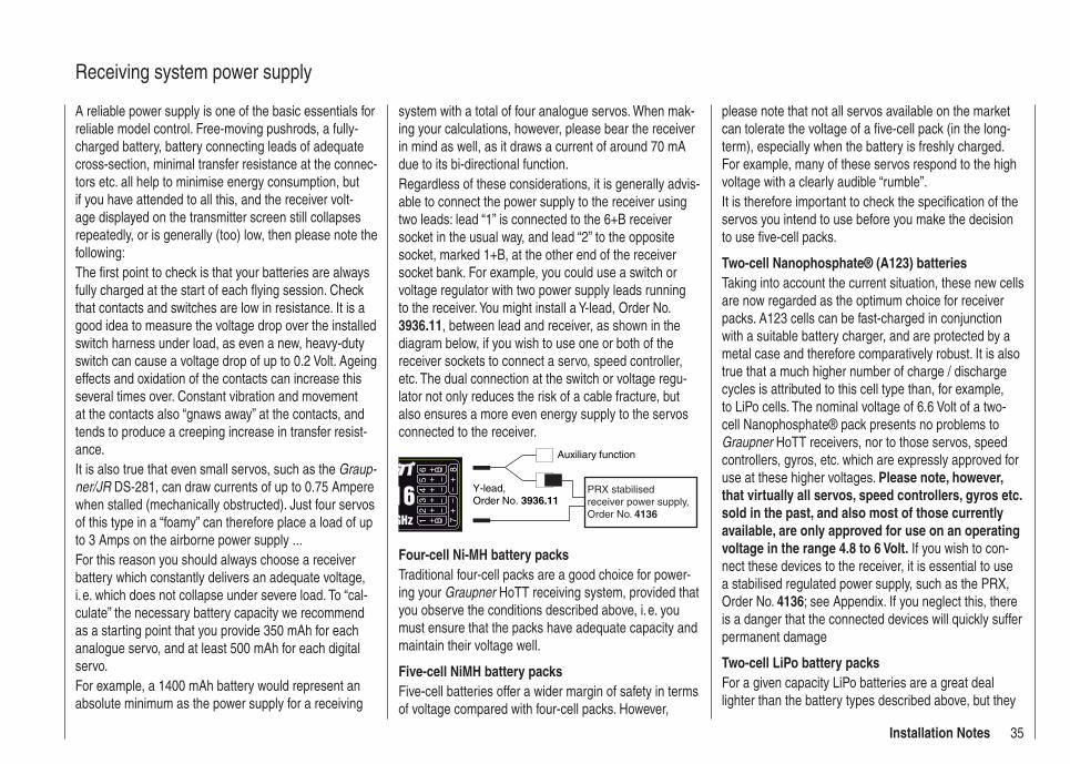
35Installation Notes
Receiving system power supply
A reliable power supply is one of the basic essentials for reliable model control. Free-moving pushrods, a fully-charged battery, battery connecting leads of adequate cross-section, minimal transfer resistance at the connec-tors etc. all help to minimise energy consumption, but if you have attended to all this, and the receiver volt-age displayed on the transmitter screen still collapses repeatedly, or is generally (too) low, then please note the following:The fi rst point to check is that your batteries are always fully charged at the start of each fl ying session. Check that contacts and switches are low in resistance. It is a good idea to measure the voltage drop over the installed switch harness under load, as even a new, heavy-duty switch can cause a voltage drop of up to 0.2 Volt. Ageing effects and oxidation of the contacts can increase this several times over. Constant vibration and movement at the contacts also “gnaws away” at the contacts, and tends to produce a creeping increase in transfer resist-ance.It is also true that even small servos, such as the Graup-ner/JR DS-281, can draw currents of up to 0.75 Ampere when stalled (mechanically obstructed). Just four servos of this type in a “foamy” can therefore place a load of up to 3 Amps on the airborne power supply ...For this reason you should always choose a receiver battery which constantly delivers an adequate voltage, i. e. which does not collapse under severe load. To “cal-culate” the necessary battery capacity we recommend as a starting point that you provide 350 mAh for each analogue servo, and at least 500 mAh for each digital servo.For example, a 1400 mAh battery would represent an absolute minimum as the power supply for a receiving
system with a total of four analogue servos. When mak-ing your calculations, however, please bear the receiver in mind as well, as it draws a current of around 70 mA due to its bi-directional function.Regardless of these considerations, it is generally advis-able to connect the power supply to the receiver using two leads: lead “1” is connected to the 6+B receiver socket in the usual way, and lead “2” to the opposite socket, marked 1+B, at the other end of the receiver socket bank. For example, you could use a switch or voltage regulator with two power supply leads running to the receiver. You might install a Y-lead, Order No. 3936.11, between lead and receiver, as shown in the diagram below, if you wish to use one or both of the receiver sockets to connect a servo, speed controller, etc. The dual connection at the switch or voltage regu-lator not only reduces the risk of a cable fracture, but also ensures a more even energy supply to the servos connected to the receiver.
Auxiliary function
Y-lead, Order No. 3936.11
PRX stabilised receiver power supply, Order No. 4136
Four-cell Ni-MH battery packsTraditional four-cell packs are a good choice for power-ing your Graupner HoTT receiving system, provided that you observe the conditions described above, i. e. you must ensure that the packs have adequate capacity and maintain their voltage well.
Five-cell NiMH battery packsFive-cell batteries offer a wider margin of safety in terms of voltage compared with four-cell packs. However,
please note that not all servos available on the market can tolerate the voltage of a fi ve-cell pack (in the long-term), especially when the battery is freshly charged. For example, many of these servos respond to the high voltage with a clearly audible “rumble”.It is therefore important to check the specifi cation of the servos you intend to use before you make the decision to use fi ve-cell packs.
Two-cell Nanophosphate® (A123) batteriesTaking into account the current situation, these new cells are now regarded as the optimum choice for receiver packs. A123 cells can be fast-charged in conjunction with a suitable battery charger, and are protected by a metal case and therefore comparatively robust. It is also true that a much higher number of charge / discharge cycles is attributed to this cell type than, for example, to LiPo cells. The nominal voltage of 6.6 Volt of a two-cell Nanophosphate® pack presents no problems to Graupner HoTT receivers, nor to those servos, speed controllers, gyros, etc. which are expressly approved for use at these higher voltages. Please note, however, that virtually all servos, speed controllers, gyros etc. sold in the past, and also most of those currently available, are only approved for use on an operating voltage in the range 4.8 to 6 Volt. If you wish to con-nect these devices to the receiver, it is essential to use a stabilised regulated power supply, such as the PRX, Order No. 4136; see Appendix. If you neglect this, there is a danger that the connected devices will quickly suffer permanent damage
Two-cell LiPo battery packsFor a given capacity LiPo batteries are a great deal lighter than the battery types described above, but they

36 Installation Notes
are more susceptible to mechanical stress and damage due to their lack of a metal case. Moreover LiPo batter-ies only have a limited ability to be fast-charged, and generally do not survive such a high number of charge / discharge cycles as is claimed for other batteries, such as Nanophosphate® types. The comparatively high nominal voltage of 7.4 Volt of a two-cell LiPo pack presents no problems to Graupner HoTT receivers, nor to those servos, speed controllers, gyros, etc. which are expressly approved for use at these higher voltages. Please note, however, that virtually all servos, speed controllers, gyros etc. sold in the past, and also most of those currently available, are only approved for use on an operating voltage in the range 4.8 to 6 Volt. If you wish to connect these devices to the re-ceiver, it is essential to use a stabilised regulated power supply, such as the PRX, Order No. 4136; see Appendix. If you neglect this, there is a danger that the connected devices will quickly suffer permanent damage.

37For your notes
38 Defi nition of terms
Defi nition of termsControl functions, transmitter controls, function inputs, control channels, mixers, switches, control switches
To make it easier for you to understand the mx-16 HoTT manual, the following section contains defi nitions of many terms which crop up again and again in the remainder of the text.
Control functionThe term “control function” can be thought of as the signal generated for a particular function which needs to be controlled - initially independent of its subsequent progress through the transmitter. In the case of fi xed-wing model aircraft the control functions include throttle, rudder and aileron, whereas collective pitch, roll and pitch-axis are typical of those used for helicopters. The signal of a control function may be assigned directly, or to several control channels simultaneously via mixers. A typical example of the latter is separate aileron ser-vos, or pairs of roll-axis or pitch-axis servos in a model helicopter. The essential feature of a control function is its infl uence on the mechanical travel of the corresponding servo.
Transmitter controlThe term “transmitter control” refers to the mechanical elements on the transmitter which are operated directly by the pilot. Their movements in turn generate corre-sponding movements in the servos, speed controllers etc. at the receiver end. The transmitter controls include the following:
The two dual-axis stick units for the control functions • 1 to 4; for both model types (“fi xed-wing” and “helicop-ter”) these four functions can be interchanged in any way you wish using the “Mode” function, e. g. throttle left or right, without having to re-connect the servos. The dual-axis stick function for throttle (or airbrakes) is often referred to as the Ch 1 (Channel 1) control.The three rotary proportional controls CTRL 6, 7 + 8•
The switches SW 4/5 and 6/7, and CTRL 9 and 10• The switches SW 1 … 3, plus 8 and 9, if they have • been assigned to a control channel in the “Transmit-ter control settings” menu.
When a proportional transmitter control is operated, the servo or servos follow the position of the control directly, whereas a switched channel provides just the two or three set servo positions.
Function inputThis is an imaginary point on the signal path, and must not be considered the same as the point on the circuit board where the transmitter control is connected! The two menus “Stick mode” and “Transmitter control settings” affect the course of the signal “after” this point, and it is possible (and likely) that there will be differences between the number of the transmitter control (as stated above) and the number of the subsequent control chan-nel.
Control channelThere is a point on the signal path where the signal con-tains all the control information required for a particular servo – this may be directly generated by a transmitter control or indirectly via a mixer – and from this point on we call the signal a “control channel”. This signal is only affected by any adjustments carried out in the “Servo settings” menu before leaving the transmitter via the RF module. Once picked up at the receiver, this signal may be modifi ed by any settings made in the Telemetry menu before fi nally passing to the corresponding servo in the model.
MixerThe transmitter’s software includes a wide range of mixer functions. Their purpose is to enable a control function to
affect multiple servos at the branching point of the mixer input, or alternatively to allow several control functions to affect one servo. For more information please refer to the numerous mixer functions as described in the section starting on page 88 of the manual.
SwitchThe three standard switches SW 2, 3 and 8, the two three-position switches SW 4/5 and 6/7 and the two momentary buttons SW 1 and 9 can also be incorpo-rated into the programming of the transmitter controls. However, all these switches are also generally intended for switching program options, e. g. starting and stopping timers, switching mixers on and off, transferring control in Trainer mode etc. Each physical switch function can be assigned to as many functions as you wish. Numerous examples are described in the manual.
Transmitter control switchIt is often desirable to switch a function on or off auto-matically at a particular position of another transmitter control, e. g. at a defi ned position of one of the dual-axis sticks. Typical examples are switching a stopwatch on and off to allow you to record the motor run time, extend-ing spoilers automatically (and many others). The mx-16 HoTT software includes a total of two (three - for helicopters) “control switches” of this type.Two transmitter control switches are available for the Ch 1 stick in each model memory, both for fi xed-wing model aircraft and helicopters. For helicopters a third is present in the form of the throttle limiter; see the right-hand side and page 67.This manual includes a range of instructive examples which make programming as simple as child’s play. Please refer to the programming examples in the section starting on page 144.
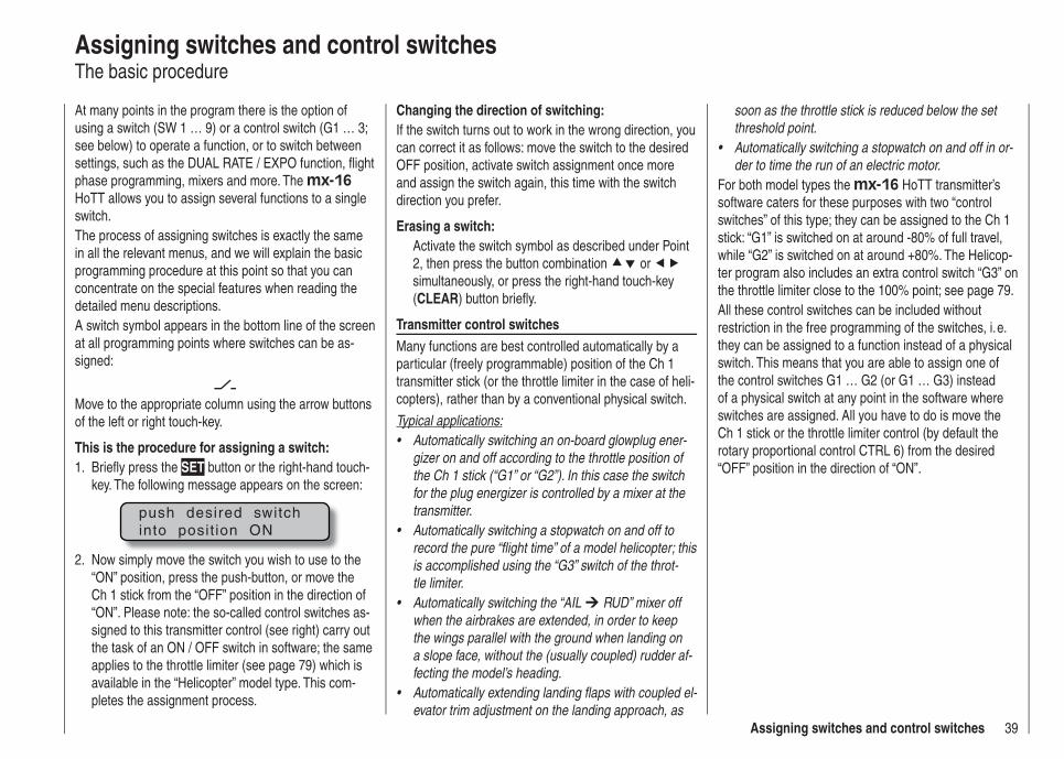
39Assigning switches and control switches
Assigning switches and control switchesThe basic procedure
At many points in the program there is the option of using a switch (SW 1 … 9) or a control switch (G1 … 3; see below) to operate a function, or to switch between settings, such as the DUAL RATE / EXPO function, fl ight phase programming, mixers and more. The mx-16 HoTT allows you to assign several functions to a single switch.The process of assigning switches is exactly the same in all the relevant menus, and we will explain the basic programming procedure at this point so that you can concentrate on the special features when reading the detailed menu descriptions.A switch symbol appears in the bottom line of the screen at all programming points where switches can be as-signed:
Move to the appropriate column using the arrow buttons of the left or right touch-key.
This is the procedure for assigning a switch:Briefl y press the 1. SET button or the right-hand touch-key. The following message appears on the screen:
push desired switchinto posit ion ON
Now simply move the switch you wish to use to the 2. “ON” position, press the push-button, or move the Ch 1 stick from the “OFF” position in the direction of “ON”. Please note: the so-called control switches as-signed to this transmitter control (see right) carry out the task of an ON / OFF switch in software; the same applies to the throttle limiter (see page 79) which is available in the “Helicopter” model type. This com-pletes the assignment process.
Changing the direction of switching:If the switch turns out to work in the wrong direction, you can correct it as follows: move the switch to the desired OFF position, activate switch assignment once more and assign the switch again, this time with the switch direction you prefer.
Erasing a switch:Activate the switch symbol as described under Point 2, then press the button combination or simultaneously, or press the right-hand touch-key (CLEAR) button briefl y.
Transmitter control switchesMany functions are best controlled automatically by a particular (freely programmable) position of the Ch 1 transmitter stick (or the throttle limiter in the case of heli-copters), rather than by a conventional physical switch.
Typical applications:Automatically switching an on-board glowplug ener-• gizer on and off according to the throttle position of the Ch 1 stick (“G1” or “G2”). In this case the switch for the plug energizer is controlled by a mixer at the transmitter.Automatically switching a stopwatch on and off to • record the pure “fl ight time” of a model helicopter; this is accomplished using the “G3” switch of the throt-tle limiter.Automatically switching the “AIL • RUD” mixer off when the airbrakes are extended, in order to keep the wings parallel with the ground when landing on a slope face, without the (usually coupled) rudder af-fecting the model’s heading.Automatically extending landing fl aps with coupled el-• evator trim adjustment on the landing approach, as
soon as the throttle stick is reduced below the set threshold point.Automatically switching a stopwatch on and off in or-• der to time the run of an electric motor.
For both model types the mx-16 HoTT transmitter’s software caters for these purposes with two “control switches” of this type; they can be assigned to the Ch 1 stick: “G1” is switched on at around -80% of full travel, while “G2” is switched on at around +80%. The Helicop-ter program also includes an extra control switch “G3” on the throttle limiter close to the 100% point; see page 79.All these control switches can be included without restriction in the free programming of the switches, i. e. they can be assigned to a function instead of a physical switch. This means that you are able to assign one of the control switches G1 … G2 (or G1 … G3) instead of a physical switch at any point in the software where switches are assigned. All you have to do is move the Ch 1 stick or the throttle limiter control (by default the rotary proportional control CTRL 6) from the desired “OFF” position in the direction of “ON”.
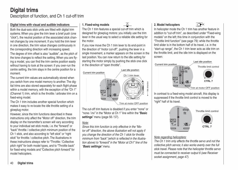
40 Digital trims
Digital trimsDescription of function, and Ch 1 cut-off trim
Digital trims with visual and audible indicatorsBoth the dual-axis stick units are fi tted with digital trim systems. When you give the trim lever a brief push (one “click”), the neutral position of the associated stick chan-nel changes by one increment. If you hold the trim lever in one direction, the trim value changes continuously in the corresponding direction with increasing speed.The degree of trim offset is also “audible”, as the pitch of the tone changes to refl ect the setting. When you are fl y-ing a model, you can fi nd the trim centre position easily without having to look at the screen: if you over-run the centre setting, the trim stays in the centre position for a moment.The current trim values are automatically stored when you switch from one model memory to another. The dig-ital trims are also stored separately for each fl ight phase within a model memory, with the exception of the “Ch 1” (Channel 1) trim, which is the throttle / airbrake trim on a fi xed-wing model.The Ch 1 trim includes another special function which makes it easy to re-locate the idle throttle setting of a glowplug motor.However, since the trim functions described in these instructions only affect the “Motor off” direction, the trim display on the transmitter’s screen will vary according to your individual set stick mode, i. e. the “forward” or “back” throttle / collective pitch minimum position of the Ch 1 stick, and also according to “left stick” or “right stick” for throttle / collective pitch. The illustrations in these instructions always refer to “Throttle / Collective pitch right” for both model types, and to “Throttle back” for fi xed-wing models and “Collective pitch forward” for model helicopters.
2. Model helicoptersIn helicopter mode the Ch 1 trim has another feature in addition to “cut-off trim”, as described under “Fixed-wing models” on the left; this time in conjunction with the “Throttle limit function” (see page 79): while the throttle limit slider is in the bottom half of its travel, i. e. in the “start-up range”, the Ch 1 trim lever acts as idle trim on the throttle limit, and the idle trim is displayed on the screen:
stop flt
50%M CTRL 7
Current trim position
Trim at motor OFF position
Last idle position
Throttle limit control
In contrast to a fi xed-wing model aircraft, this display is suppressed if the throttle limit control is moved to the “right” half of its travel.
stop flt
50%M
CTRL 7
Throttle limit control
Note regarding helicopters:The Ch 1 trim only affects the throttle servo and not the collective pitch servos; it also works evenly over the full stick travel. Please note that the helicopter throttle servo must be connected to receiver output 6 (see Receiver socket assignment, page 47).
1. Fixed-wing modelsThe Ch 1 trim features a special cut-off trim which is designed for glowplug motors: you initially use the trim lever in the usual way to select a reliable idle setting for the motor.If you now move the Ch 1 trim lever to its end-point in the direction of “motor cut-off”, pushing the lever in a single movement, a marker appears on the screen in the last position. You can now return to the idle setting for starting the motor simply by pushing the stick one click in the direction of “open throttle”.
stop flt
50%
Current trim position
M
Trim at motor OFF position
Last idle position
Idle
dire
ctio
n
Ch 1 trim lever
The cut-off trim feature is disabled if you enter “none” or “none / inv” in the “Motor at Ch 1” line within the “Basic settings” menu (page 56 / 57).
Note:Since this trim function is only effective in the “Mo-tor off” direction, the above illustration will not apply if you change the direction of the Ch 1 stick for throttle minimum from “back” (which is refl ected in the illustra-tion above) to “forward” in the “Motor at Ch1” line of the “Basic settings” menu.

41For your notes
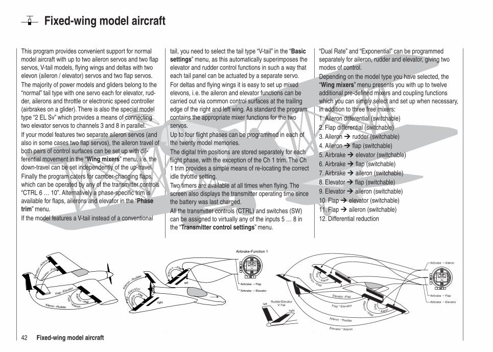
42 Fixed-wing model aircraft
Fixed-wing model aircraft
This program provides convenient support for normal model aircraft with up to two aileron servos and two fl ap servos, V-tail models, fl ying wings and deltas with two elevon (aileron / elevator) servos and two fl ap servos.The majority of power models and gliders belong to the “normal” tail type with one servo each for elevator, rud-der, ailerons and throttle or electronic speed controller (airbrakes on a glider). There is also the special model type “2 EL Sv” which provides a means of connecting two elevator servos to channels 3 and 8 in parallel.If your model features two separate aileron servos (and also in some cases two fl ap servos), the aileron travel of both pairs of control surfaces can be set up with dif-ferential movement in the “Wing mixers” menu, i. e. the down-travel can be set independently of the up-travel.Finally the program caters for camber-changing fl aps, which can be operated by any of the transmitter controls “CTRL 6 … 10”. Alternatively a phase-specifi c trim is available for fl aps, ailerons and elevator in the “Phase trim” menu.If the model features a V-tail instead of a conventional
tail, you need to select the tail type “V-tail” in the “Basic settings” menu, as this automatically superimposes the elevator and rudder control functions in such a way that each tail panel can be actuated by a separate servo.For deltas and fl ying wings it is easy to set up mixed elevons, i. e. the aileron and elevator functions can be carried out via common control surfaces at the trailing edge of the right and left wing. As standard the program contains the appropriate mixer functions for the two servos.Up to four fl ight phases can be programmed in each of the twenty model memories.The digital trim positions are stored separately for each fl ight phase, with the exception of the Ch 1 trim. The Ch 1 trim provides a simple means of re-locating the correct idle throttle setting.Two timers are available at all times when fl ying. The screen also displays the transmitter operating time since the battery was last charged.All the transmitter controls (CTRL) and switches (SW) can be assigned to virtually any of the inputs 5 … 8 in the “Transmitter control settings” menu.
“Dual Rate” and “Exponential” can be programmed separately for aileron, rudder and elevator, giving two modes of control.Depending on the model type you have selected, the “Wing mixers” menu presents you with up to twelve additional pre-defi ned mixers and coupling functions which you can simply select and set up when necessary, in addition to three free mixers:1. Aileron differential (switchable)2. Flap differential (switchable)3. Aileron rudder (switchable)4. Aileron fl ap (switchable)5. Airbrake elevator (switchable)6. Airbrake fl ap (switchable)7. Airbrake aileron (switchable)8. Elevator fl ap (switchable)9. Elevator aileron (switchable)10. Flap elevator (switchable)11. Flap aileron (switchable)12. Differential reduction
Ele
vato
r �Flap
Flap � Elevator
Fla
p�
Aileron
Aile ron
� FlapAileron
� Rudder
Eev
ator�
Aileron
left
rightElev
ator �
Flap
Fla
p�
ElevatorAile
ron �
Rudder Aile
ro
n � Flap
Airbrake � Flap
Airbrake � Elevator
Airbrake-Function 1
left
right
Rudder/ElevatorV-Tail
Elevator � Aileron
Aileron � Rudder
Flap � Elevator
Elevator� Flap
Aile
r on
�
Flap
Flap�
A leron
Fla
p
� Aleron
Aile
r on
�
Flap
Airbrake � Flap
Airbrake � Elevator
Airbrake � Aileron

43Fixed-wing models: receiver assignment
Installation notesThe servos MUST be connected to the receiver outputs in the following order:Outputs not required are simply left vacant.Please note the following points in particular:
If you are using only one aileron servo, receiver out-• put 5 (right aileron) is left unused; it can also be used for another purpose if you select “1 AIL” in the “Basic settings” menu.If you are using only one fl ap servo, receiver output 7 • (right fl ap) MUST be left unused, assuming that you have selected “2 FL” in the “Basic settings” menu.
Please also read the information on the following pages.
Receiver socket assignment for models with up to two ailerons and two fl aps, plus “normal” tail type, V-tail, and two elevator servos (3 + 8)
Ser
vo4
8 V
C 5
77B
esN
r 4
101
Receiver battery
Switch harness
Telemetry sensor
Y-lead, Order No. 3936.11
Receiver
3 = Elevator / left V-tail
2 = Aileron / left aileron
8 = 2nd elevator / aux. function
7 = Right fl ap / reserve
5 = Right aileron / reserve
4 = Rudder / right V-tail
1 = Throttle / brake
6 = Flap / left fl ap / reserve
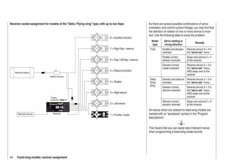
44 Fixed-wing models: receiver assignment
Receiver socket assignment for models of the “Delta / Flying wing” type, with up to two fl aps
Se
vo4
8 V
C 5
77B
esN
r 4
101
Receiver battery
Switch harness
Telemetry sensor
Y-lead, Order No. 3936.11
Receiver
3 = Right elevon
2 = Left elevon
8 = Auxiliary function
7 = Right fl ap / reserve
5 = Reserve function
4 = Rudder
1 = Throttle / brake
6 = Flap / left fl ap / reserve
As there are several possible combinations of servo orientation and control surface linkage, you may fi nd that the direction of rotation of one or more servos is incor-rect. Use the following table to solve the problem.
Model type
Servo rotating in wrong direction
Remedy
V-tail Rudder and elevator reversed
Reverse servos 3 + 4 in the “servo set.” menu
Rudder correct, elevator reversed
Swap over servos 3 + 4 at the receiver
Elevator correct, rudder reversed
Reverse servos 3 + 4 in the “servo set.” menu, AND swap over at the receiver
Delta,fl ying wing
Elevator and ailerons reversed
Reverse servos 2 + 3 in the “servo set.” menu
Elevator correct, ailerons reversed
Reverse servos 2 + 3 in the “servo set.” menu, AND swap over at the receiver
Ailerons correct, elevator reversed
Swap over servos 2 + 3 at the receiver
All menus which are relevant to fi xed-wing models are marked with an “aeroplane” symbol in the “Program descriptions”:
This means that you can easily skip irrelevant menus when programming a fi xed-wing model aircraft.

45For your notes
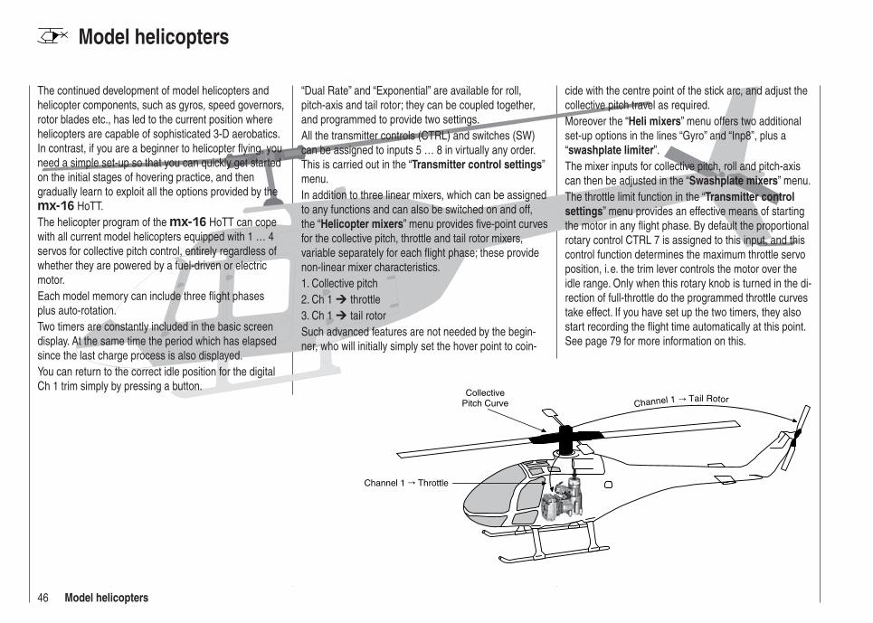
46 Model helicopters
Model helicopters
Collective Pitch Curve
Channel 1 Throttle
Channel 1 Tail Rotor
The continued development of model helicopters and helicopter components, such as gyros, speed governors, rotor blades etc., has led to the current position where helicopters are capable of sophisticated 3-D aerobatics. In contrast, if you are a beginner to helicopter fl ying, you need a simple set-up so that you can quickly get started on the initial stages of hovering practice, and then gradually learn to exploit all the options provided by the mx-16 HoTT.The helicopter program of the mx-16 HoTT can cope with all current model helicopters equipped with 1 … 4 servos for collective pitch control, entirely regardless of whether they are powered by a fuel-driven or electric motor.Each model memory can include three fl ight phases plus auto-rotation.Two timers are constantly included in the basic screen display. At the same time the period which has elapsed since the last charge process is also displayed.You can return to the correct idle position for the digital Ch 1 trim simply by pressing a button.
“Dual Rate” and “Exponential” are available for roll, pitch-axis and tail rotor; they can be coupled together, and programmed to provide two settings.All the transmitter controls (CTRL) and switches (SW) can be assigned to inputs 5 … 8 in virtually any order. This is carried out in the “Transmitter control settings” menu.In addition to three linear mixers, which can be assigned to any functions and can also be switched on and off, the “Helicopter mixers” menu provides fi ve-point curves for the collective pitch, throttle and tail rotor mixers, variable separately for each fl ight phase; these provide non-linear mixer characteristics.1. Collective pitch2. Ch 1 throttle3. Ch 1 tail rotorSuch advanced features are not needed by the begin-ner, who will initially simply set the hover point to coin-
cide with the centre point of the stick arc, and adjust the collective pitch travel as required.Moreover the “Heli mixers” menu offers two additional set-up options in the lines “Gyro” and “Inp8”, plus a “swashplate limiter”.The mixer inputs for collective pitch, roll and pitch-axis can then be adjusted in the “Swashplate mixers” menu.The throttle limit function in the “Transmitter control settings” menu provides an effective means of starting the motor in any fl ight phase. By default the proportional rotary control CTRL 7 is assigned to this input, and this control function determines the maximum throttle servo position, i. e. the trim lever controls the motor over the idle range. Only when this rotary knob is turned in the di-rection of full-throttle do the programmed throttle curves take effect. If you have set up the two timers, they also start recording the fl ight time automatically at this point. See page 79 for more information on this.
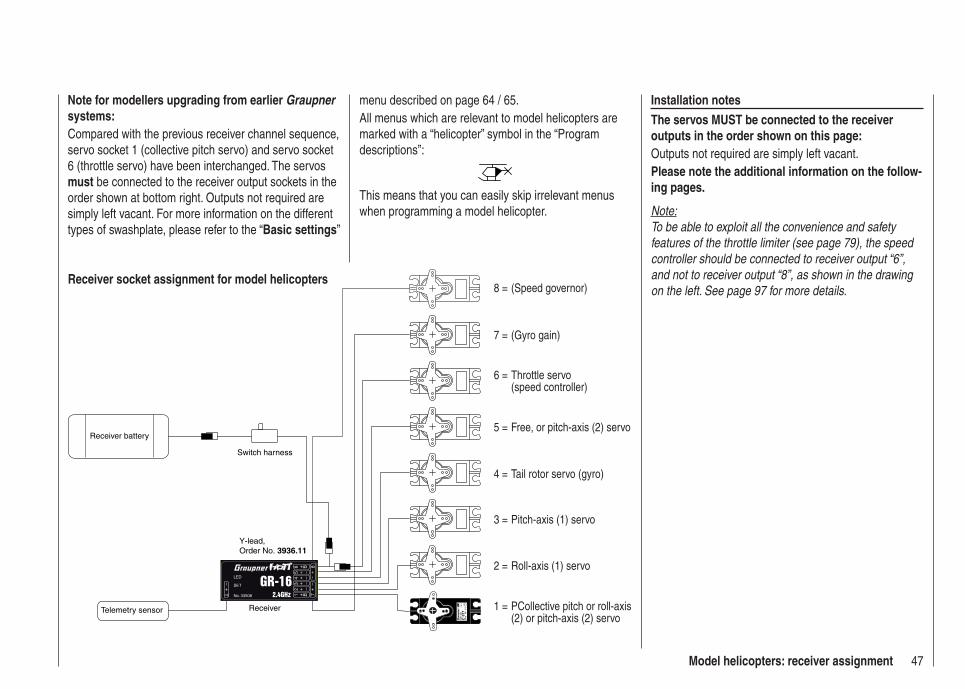
47Model helicopters: receiver assignment
Receiver socket assignment for model helicopters
Note for modellers upgrading from earlier Graupner systems:Compared with the previous receiver channel sequence, servo socket 1 (collective pitch servo) and servo socket 6 (throttle servo) have been interchanged. The servos must be connected to the receiver output sockets in the order shown at bottom right. Outputs not required are simply left vacant. For more information on the different types of swashplate, please refer to the “Basic settings”
menu described on page 64 / 65.All menus which are relevant to model helicopters are marked with a “helicopter” symbol in the “Program descriptions”:
This means that you can easily skip irrelevant menus when programming a model helicopter.
Installation notesThe servos MUST be connected to the receiver outputs in the order shown on this page:Outputs not required are simply left vacant.Please note the additional information on the follow-ing pages.
Note:To be able to exploit all the convenience and safety features of the throttle limiter (see page 79), the speed controller should be connected to receiver output “6”, and not to receiver output “8”, as shown in the drawing on the left. See page 97 for more details.
Se
vo4
8 V
C 5
77B
esN
r 4
10
Receiver battery
Switch harness
Telemetry sensor
Y-lead, Order No. 3936.11
Receiver 1 = PCollective pitch or roll-axis (2) or pitch-axis (2) servo
2 = Roll-axis (1) servo
3 = Pitch-axis (1) servo
5 = Free, or pitch-axis (2) servo
4 = Tail rotor servo (gyro)
6 = Throttle servo (speed controller)
7 = (Gyro gain)
8 = (Speed governor)
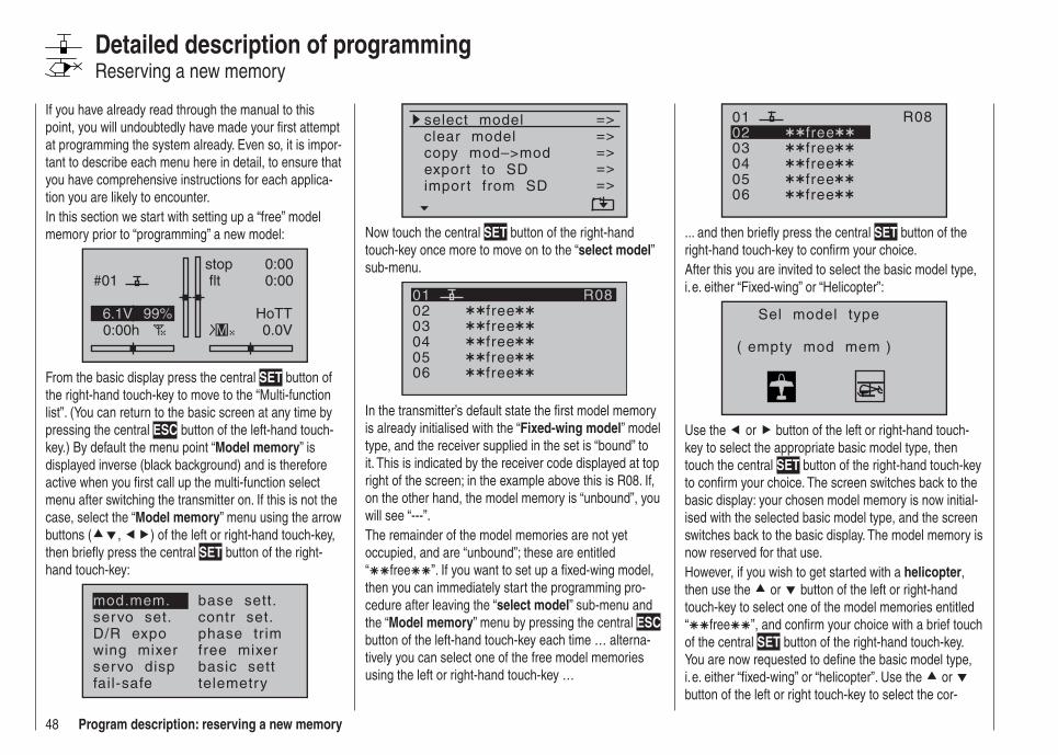
48 Program description: reserving a new memory
If you have already read through the manual to this point, you will undoubtedly have made your fi rst attempt at programming the system already. Even so, it is impor-tant to describe each menu here in detail, to ensure that you have comprehensive instructions for each applica-tion you are likely to encounter.In this section we start with setting up a “free” model memory prior to “programming” a new model:
#01
0:00h
stop flt
0:000:00
0.0V6.1V HoTT
M99%
From the basic display press the central SET button of the right-hand touch-key to move to the “Multi-function list”. (You can return to the basic screen at any time by pressing the central ESC button of the left-hand touch-key.) By default the menu point “Model memory” is displayed inverse (black background) and is therefore active when you fi rst call up the multi-function select menu after switching the transmitter on. If this is not the case, select the “Model memory” menu using the arrow buttons ( , ) of the left or right-hand touch-key, then briefl y press the central SET button of the right-hand touch-key:
mod.mem.servo set.D/R expowing mixer
base sett.contr set.phase tr imfree mixer
servo disp basic settfail-safe telemetry
Detailed description of programmingReserving a new memory
select modelclear modelcopy mod–>mod
=>=>=>
expor t to SDimpor t from SD
=>=>=>
Now touch the central SET button of the right-hand touch-key once more to move on to the “select model” sub-menu.
030405
free0201
06
R08
freefreefreefree
In the transmitter’s default state the fi rst model memory is already initialised with the “Fixed-wing model” model type, and the receiver supplied in the set is “bound” to it. This is indicated by the receiver code displayed at top right of the screen; in the example above this is R08. If, on the other hand, the model memory is “unbound”, you will see “---”.The remainder of the model memories are not yet occupied, and are “unbound”; these are entitled “ free ”. If you want to set up a fi xed-wing model, then you can immediately start the programming pro-cedure after leaving the “select model” sub-menu and the “Model memory” menu by pressing the central ESC button of the left-hand touch-key each time … alterna-tively you can select one of the free model memories using the left or right-hand touch-key …
030405
free0201
06
R08
freefreefreefree
... and then briefl y press the central SET button of the right-hand touch-key to confi rm your choice.After this you are invited to select the basic model type, i. e. either “Fixed-wing” or “Helicopter”:
Sel model type
( empty mod mem )
Use the or button of the left or right-hand touch-key to select the appropriate basic model type, then touch the central SET button of the right-hand touch-key to confi rm your choice. The screen switches back to the basic display: your chosen model memory is now initial-ised with the selected basic model type, and the screen switches back to the basic display. The model memory is now reserved for that use.However, if you wish to get started with a helicopter, then use the or button of the left or right-hand touch-key to select one of the model memories entitled “ free ”, and confi rm your choice with a brief touch of the central SET button of the right-hand touch-key. You are now requested to defi ne the basic model type, i. e. either “fi xed-wing” or “helicopter”. Use the or button of the left or right touch-key to select the cor-

49Program description: reserving a new memory
directly to the corresponding option. For more de-tailed information on binding a receiver please refer to pages 61 and 70.Beneath the “BIND. n/v” warning described earlier • you will also see the warning …
fai l safesetupt.b.d
… for a few seconds as an indication that no Fail-Safe settings have been entered yet. For more infor-mation on this please refer to page 116.If the warning …•
thrott letoo
high !
… appears on the screen, move the throttle stick (or the limiter - by default the rotary knob CTRL 6 - if set-ting up a helicopter) back to idle. This warning only appears in accordance with the settings you have en-tered in the “Motor at Ch1” or “Collective pitch min.” section of the “Basic settings” menu, as described on pages 56 and 67. If you are setting up a non-pow-ered fi xed-wing model, enter “none” or “none/inv” at this point; this disables the throttle warning message, and makes available the “Brake NN *“ mixers in the “Wing mixers” menu, which would otherwise be suppressed.If the transmitter’s model memories are already occu-• pied, then a pictogram of the selected model type ap-pears in the appropriate model memory, followed by a blank line, or the model’s name if a name has al-
responding symbol, then again press the central SET button of the right-hand touch-key briefl y in confi rmation. This initialises the selected model type for the model memory you have just selected, and you can now start programming your model in this memory.It is now only possible to change this memory to a dif-ferent model type if you fi rst erase the model memory (“Model memory” menu, page 52).
Notes:If you wish to erase the model memory which is cur-• rently active in the basic display, you will have to de-fi ne one of the two model types “fi xed-wing” or “heli-copter” immediately after completing the erase procedure. You cannot avoid making this choice by switching the transmitter off. If you wish to remove a model memory which you inadvertently occupied, you can simply erase it from a different model mem-ory.However, if you erase a model memory which is not currently active, after the procedure you will see the memory marked as “ free ” under Model Se-lect.After the selected model memory has been initial-• ised with your preferred basic model type, the screen shifts to the newly reserved model memory. At the same time the following warning appears for a few seconds …
BIND N/AOK
… as an indication that this memory has not yet been bound to a receiver. With a brief touch of the central SET button of the right-hand touch-key you can move
* NN = Nomen Nominandum (name to be stated)
ready been entered in the “Basic settings” menu (pages 56 and 64), together with an indicator that the memory is bound to a receiver, if appropriate.If the battery voltage is too low, the software prevents • you switching model memories in the interests of safety. In this case the screen displays this message:
not possible nowvoltage too low
Basically there are now four different options for assign-ing the four control functions aileron, elevator, rudder and throttle / airbrakes (fi xed-wing model), and roll, pitch-axis, tail rotor and throttle / collective pitch (model helicopter) to the two primary dual-axis sticks. Which of these options is adopted depends on the personal pref-erence of the individual model pilot. This function is set in the “Stick mode” line for the currently active model memory in the “Basic settings” menu (page 56 or 64):
mod Namestick mode
CH8 delaymotor at C1
1
yesno
tail type normal
As mentioned earlier, for maximum fl exibility the trans-mitter controls 5 … 8 are by default not assigned to transmitter controls, and can be assigned to any chan-nels you like; this also helps to avoid accidental mishan-dling.This means that in the default state of the equipment only those servos connected to receiver outputs 1 … 4 can usually be controlled by the two dual-axis sticks, whereas servos connected to sockets 5 …

50 Program description: reserving a new memory
max. 8 remain steadfastly at their centre position. If you set up a new model helicopter, servo 6 may also re-spond to some extent to the controls - depending on the position of the throttle limiter CTRL 6. For both model types this situation only changes once you have carried out the appropriate assignments in the “Transmitter control settings” menu.If you wish to use a newly initialised model memory, then this MUST fi rst be “bound” to a (further) receiver before any servos connected to the receiver can be con-trolled from the transmitter. For more information on this please refer to the “Binding” section on pages 61 and 70.You will fi nd a description of the basic steps for program-ming a fi xed-wing model aircraft in the Programming Examples section starting on page 144; for model helicopters the equivalent section starts on page 166.The following menu descriptions are arranged in the order that they are listed in the individual menus in the multi-function list.

51For your notes
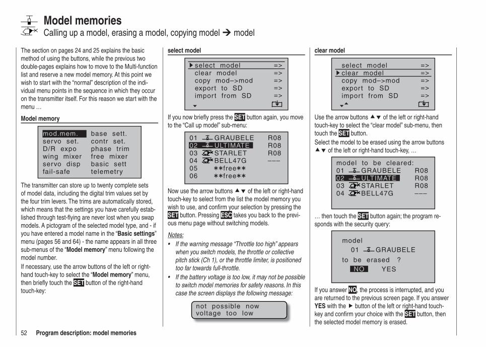
52 Program description: model memories
The section on pages 24 and 25 explains the basic method of using the buttons, while the previous two double-pages explains how to move to the Multi-function list and reserve a new model memory. At this point we wish to start with the “normal” description of the indi-vidual menu points in the sequence in which they occur on the transmitter itself. For this reason we start with the menu …
Model memory
mod.mem.servo set.D/R expowing mixer
base sett.contr set.phase tr imfree mixer
servo disp basic settfail-safe telemetry
The transmitter can store up to twenty complete sets of model data, including the digital trim values set by the four trim levers. The trims are automatically stored, which means that the settings you have carefully estab-lished through test-fl ying are never lost when you swap models. A pictogram of the selected model type, and - if you have entered a model name in the “Basic settings” menu (pages 56 and 64) - the name appears in all three sub-menus of the “Model memory” menu following the model number.If necessary, use the arrow buttons of the left or right-hand touch-key to select the “Model memory” menu, then briefl y touch the SET button of the right-hand touch-key:
Model memoriesCalling up a model, erasing a model, copying model model
clear model
select modelclear modelcopy mod–>mod
=>=>=>
=>expor t to SDimpor t from SD
=>=>
Use the arrow buttons of the left or right-hand touch-key to select the “clear model” sub-menu, then touch the SET button.Select the model to be erased using the arrow buttons
of the left or right-hand touch-key, …
01
0304
ULTIMATE02GRAUBELE
STARLETBELL47G
model to be cleared:R08R08R08–––
… then touch the SET button again; the program re-sponds with the security query:
modelGRAUBELE
to be erased ?NO YES
01
If you answer NO, the process is interrupted, and you are returned to the previous screen page. If you answer YES with the button of the left or right-hand touch-key and confi rm your choice with the SET button, then the selected model memory is erased.
select model
select modelclear modelcopy mod–>mod
=>=>=>
expor t to SDimpor t from SD
=>=>=>
If you now briefl y press the SET button again, you move to the “Call up model” sub-menu:
01
030405 free
ULTIMATE02GRAUBELE
STARLETBELL47G
06 free
R08R08R08–––
Now use the arrow buttons of the left or right-hand touch-key to select from the list the model memory you wish to use, and confi rm your selection by pressing the SET button. Pressing ESC takes you back to the previ-ous menu page without switching models.
Notes:If the warning message “Throttle too high” appears • when you switch models, the throttle or collective pitch stick (Ch 1), or the throttle limiter, is positioned too far towards full-throttle.If the battery voltage is too low, it may not be possible • to switch model memories for safety reasons. In this case the screen displays the following message:
not possible nowvoltage too low
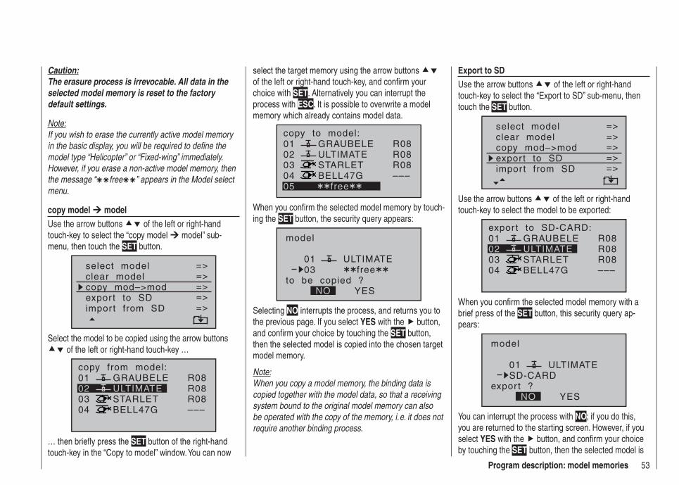
53Program description: model memories
select the target memory using the arrow buttons of the left or right-hand touch-key, and confi rm your choice with SET. Alternatively you can interrupt the process with ESC. It is possible to overwrite a model memory which already contains model data.
01
0304
ULTIMATE02GRAUBELE
STARLETBELL47G
copy to model:
05 free
R08R08R08–––
When you confi rm the selected model memory by touch-ing the SET button, the security query appears:
model
ULTIMATE
to be copied ?NO YES
0103 free
Selecting NO interrupts the process, and returns you to the previous page. If you select YES with the button, and confi rm your choice by touching the SET button, then the selected model is copied into the chosen target model memory.
Note:When you copy a model memory, the binding data is copied together with the model data, so that a receiving system bound to the original model memory can also be operated with the copy of the memory, i. e. it does not require another binding process.
Caution:The erasure process is irrevocable. All data in the selected model memory is reset to the factory default settings.
Note:If you wish to erase the currently active model memory in the basic display, you will be required to defi ne the model type “Helicopter” or “Fixed-wing” immediately. However, if you erase a non-active model memory, then the message “ free ” appears in the Model select menu.
copy model modelUse the arrow buttons of the left or right-hand touch-key to select the “copy model model” sub-menu, then touch the SET button.
select modelclear modelcopy mod–>mod
=>=>=>
=>expor t to SDimpor t from SD
=>=>
Select the model to be copied using the arrow buttons of the left or right-hand touch-key …
01
0304
ULTIMATE02GRAUBELE
STARLETBELL47G
copy from model:R08R08R08–––
… then briefl y press the SET button of the right-hand touch-key in the “Copy to model” window. You can now
Export to SDUse the arrow buttons of the left or right-hand touch-key to select the “Export to SD” sub-menu, then touch the SET button.
select modelclear modelcopy mod–>mod
=>=>=>
=>=>
expor t to SDimpor t from SD
=>=>
Use the arrow buttons of the left or right-hand touch-key to select the model to be exported:
01
0304
ULTIMATE02GRAUBELE
STARLETBELL47G
expor t to SD-CARD:R08R08R08–––
When you confi rm the selected model memory with a brief press of the SET button, this security query ap-pears:
model
ULTIMATE
expor t ?NO YES
01SD-CARD
You can interrupt the process with NO; if you do this, you are returned to the starting screen. However, if you select YES with the button, and confi rm your choice by touching the SET button, then the selected model is
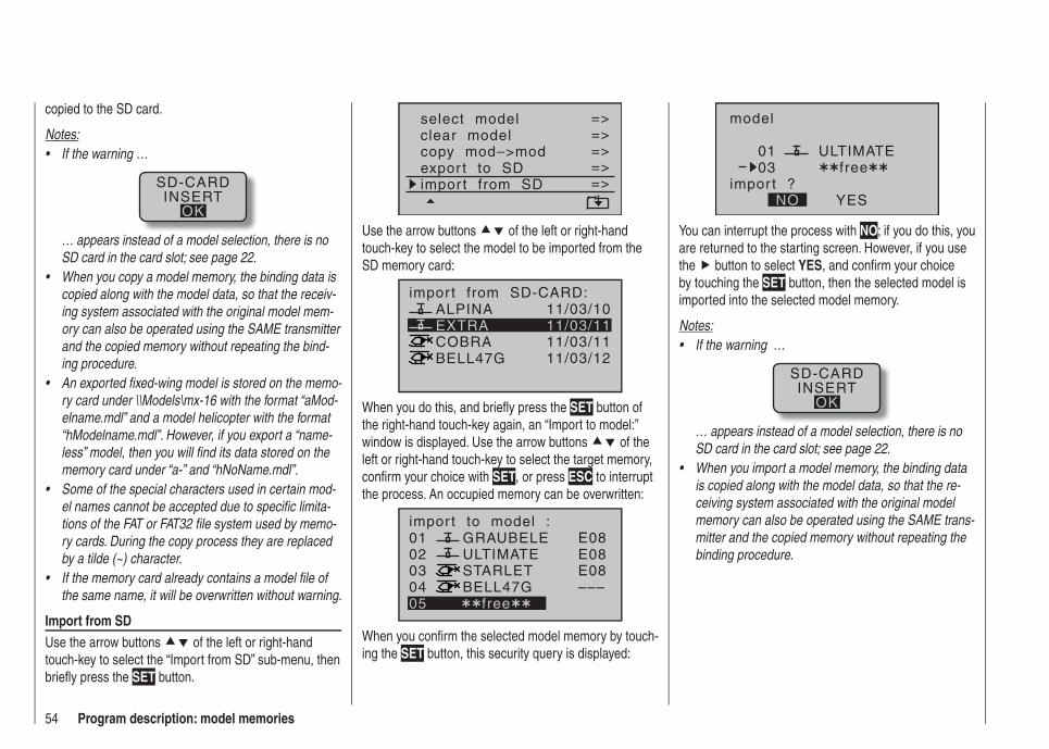
54 Program description: model memories
copied to the SD card.
Notes:If the warning …•
SD-CARDINSERT
OK
… appears instead of a model selection, there is no SD card in the card slot; see page 22.When you copy a model memory, the binding data is • copied along with the model data, so that the receiv-ing system associated with the original model mem-ory can also be operated using the SAME transmitter and the copied memory without repeating the bind-ing procedure.An exported fi xed-wing model is stored on the memo-• ry card under \\Models\mx-16 with the format “aMod-elname.mdl” and a model helicopter with the format “hModelname.mdl”. However, if you export a “name-less” model, then you will fi nd its data stored on the memory card under “a-” and “hNoName.mdl”.Some of the special characters used in certain mod-• el names cannot be accepted due to specifi c limita-tions of the FAT or FAT32 fi le system used by memo-ry cards. During the copy process they are replaced by a tilde (~) character.If the memory card already contains a model fi le of • the same name, it will be overwritten without warning.
Import from SDUse the arrow buttons of the left or right-hand touch-key to select the “Import from SD” sub-menu, then briefl y press the SET button.
select modelclear modelcopy mod–>mod
=>=>=>=>=>
expor t to SDimpor t from SD
=>=>
Use the arrow buttons of the left or right-hand touch-key to select the model to be imported from the SD memory card:
EXTRAALPINA
COBRABELL47G
impor t from SD-CARD:11/03/1011/03/1111/03/1111/03/12
When you do this, and briefl y press the SET button of the right-hand touch-key again, an “Import to model:” window is displayed. Use the arrow buttons of the left or right-hand touch-key to select the target memory, confi rm your choice with SET, or press ESC to interrupt the process. An occupied memory can be overwritten:
01
0304
ULTIMATE02GRAUBELE
STARLETBELL47G
impor t to model :
05 free
E08E08E08–––
When you confi rm the selected model memory by touch-ing the SET button, this security query is displayed:
model
ULTIMATE
impor t ?NO YES
0103 free
You can interrupt the process with NO; if you do this, you are returned to the starting screen. However, if you use the button to select YES, and confi rm your choice by touching the SET button, then the selected model is imported into the selected model memory.
Notes:If the warning …•
SD-CARDINSERT
OK
… appears instead of a model selection, there is no SD card in the card slot; see page 22.When you import a model memory, the binding data • is copied along with the model data, so that the re-ceiving system associated with the original model memory can also be operated using the SAME trans-mitter and the copied memory without repeating the binding procedure.

55For your notes
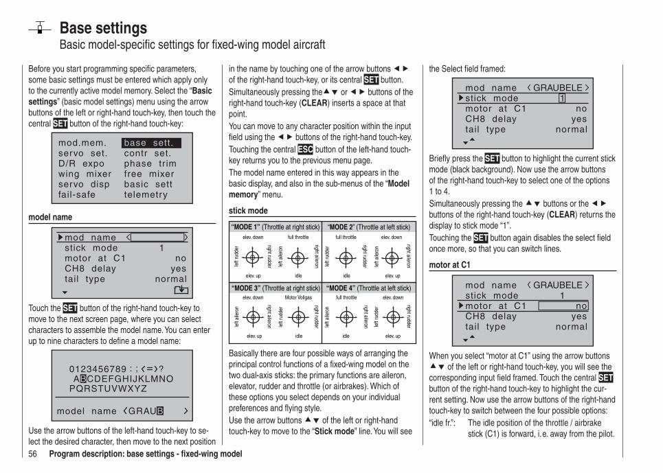
56 Program description: base settings - fi xed-wing model
Base settingsBasic model-specifi c settings for fi xed-wing model aircraft
Before you start programming specifi c parameters, some basic settings must be entered which apply only to the currently active model memory. Select the “Basic settings” (basic model settings) menu using the arrow buttons of the left or right-hand touch-key, then touch the central SET button of the right-hand touch-key:
mod.mem.servo set.D/R expowing mixer
base sett.contr set.phase tr imfree mixer
servo disp basic settfail-safe telemetry
model name
mod namestick mode
CH8 delaymotor at C1
1
yesno
tail type normal
Touch the SET button of the right-hand touch-key to move to the next screen page, where you can select characters to assemble the model name. You can enter up to nine characters to defi ne a model name:
0123456789
PQRSTUVWXYZ
model name
?: ;ABCDEFGHIJKLMNO
GRAUB
Use the arrow buttons of the left-hand touch-key to se-lect the desired character, then move to the next position
in the name by touching one of the arrow buttons of the right-hand touch-key, or its central SET button.Simultaneously pressing the or buttons of the right-hand touch-key (CLEAR) inserts a space at that point.You can move to any character position within the input fi eld using the buttons of the right-hand touch-key.Touching the central ESC button of the left-hand touch-key returns you to the previous menu page.The model name entered in this way appears in the basic display, and also in the sub-menus of the “Model memory” menu.
stick mode
“MODE 2” (Throttle at left stick)
“MODE 3” (Throttle at right stick) “MODE 4” (Throttle at left stick)
“MODE 1” (Throttle at right stick)elev. down
elev. up
left
rudd
er
right rudder
full throttle
idlele
ft ai
lero
n
right aileron
full throttle
left
rudd
er
right rudder
idle
elev. down
elev. up
left
aile
ron
right aileron
elev. down
elev. up
left
aile
ron
right aileron
Motor Vollgas
idle
left
rudd
er
right rudder
full throttle
idle
left
aile
ron
right aileronelev. down
elev. up
left
rudd
er
right rudder
Basically there are four possible ways of arranging the principal control functions of a fi xed-wing model on the two dual-axis sticks: the primary functions are aileron, elevator, rudder and throttle (or airbrakes). Which of these options you select depends on your individual preferences and fl ying style.Use the arrow buttons of the left or right-hand touch-key to move to the “Stick mode” line. You will see
the Select fi eld framed:
mod namestick mode
CH8 delaymotor at C1
1
yesno
tail type normal
GRAUBELE
Briefl y press the SET button to highlight the current stick mode (black background). Now use the arrow buttons of the right-hand touch-key to select one of the options 1 to 4.Simultaneously pressing the buttons or the buttons of the right-hand touch-key (CLEAR) returns the display to stick mode “1”.Touching the SET button again disables the select fi eld once more, so that you can switch lines.
motor at C1
mod namestick mode
CH8 delaymotor at C1
1
yesno
tail type normal
GRAUBELE
When you select “motor at C1” using the arrow buttons of the left or right-hand touch-key, you will see the
corresponding input fi eld framed. Touch the central SET button of the right-hand touch-key to highlight the cur-rent setting. Now use the arrow buttons of the right-hand touch-key to switch between the four possible options: “idle fr.”: The idle position of the throttle / airbrake
stick (C1) is forward, i. e. away from the pilot.
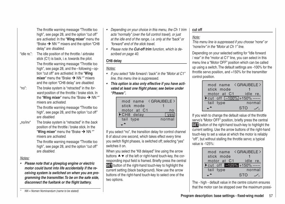
57Program description: base settings - fi xed-wing model
Depending on your choice in this menu, the Ch 1 trim • acts “normally” (over the full control travel), or just at the idle end of the range, i. e. only at the “back” or “forward” end of the stick travel.Please note the • Cut-off trim function, which is de-scribed on page 40.
CH8 delay
Notes:If you select “Idle forward / back” in the “Motor at C1” • line, this menu line is suppressed.This option is also only effective if you have acti-• vated at least one fl ight phase; see below under “Phases”.
mod namestick mode
CH8 delaymotor at C1
1
yesno
tail type normal
GRAUBELE
If you select “no”, the transition delay for control channel 8 of about one second, which takes effect every time you switch fl ight phases, is switched off; selecting “yes” switches it on.When you select the “K8 delayed” line using the arrow buttons of the left or right-hand touch-key, the cor-responding input fi eld is framed. Briefl y press the central SET button of the right-hand touch-key to highlight the current setting (black background). Now use the arrow buttons of the right-hand touch-key to select one of the two options.
The throttle warning message “Throttle too high”, see page 28, and the option “cut off” are activated. In the “Wing mixer” menu the “Brake NN *” mixers and the option “CH8 delay” are disabled.
“idle re.”: The idle position of the throttle / airbrake stick (C1) is back, i. e. towards the pilot.
The throttle warning message “Throttle too high”, see page 28, and the – following – op-tion “cut off” are activated. In the “Wing mixer” menu the “Brake NN *” mixers and the option “CH8 delay” are disabled.
“no”: The brake system is “retracted” in the for-ward position of the throttle / brake stick. In the “Wing mixer” menu the “Brake NN *” mixers are activated.
The throttle warning message “Throttle too high”, see page 28, and the option “cut off” are disabled.
„no/inv“ The brake system is “retracted” in the back position of the throttle / brake stick. In the “Wing mixer” menu the “Brake NN *” mixers are activated.
The throttle warning message “Throttle too high”, see page 28, and the option “cut off” are disabled.
Notes:Please note that a glowplug engine or electric • motor could burst into life accidentally if the re-ceiving system is switched on when you are pro-gramming the transmitter. To be on the safe side, disconnect the fueltank or the fl ight battery.
cut off
Note:This menu line is suppressed if you choose “none” or “none/inv” in the “Motor at Ch 1” line.
Depending on your selected setting for “Idle forward / rear” in the “motor at C1” line, you can select in this menu line a “Motor OFF” position which can be called up using a switch. The default settings are -100% for the throttle servo position, and +150% for the transmitter control position.
mod namestick modemotor at C1
1idle re.
tail type normal
GRAUBELE
cut off –––+150%–100%
STO
If you wish to change the default value of the throttle servo’s “Motor OFF” position, briefl y press the central SET button of the right-hand touch-key to highlight the current setting. Use the arrow buttons of the right-hand touch-key to set a value at which the motor is reliably “off”, but without stalling the throttle servo; a typical value is -125%:
mod namestick modemotor at C1
1idle re.
tail type normal
GRAUBELE
cut off –––+150%
STO
–125%
The - high - default value in the centre column ensures that the motor can be stopped over the maximum possi-
* NN = Nomen Nominandum (name to be stated)
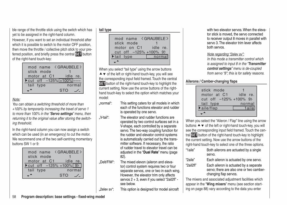
58 Program description: base settings - fi xed-wing model
ble range of the throttle stick using the switch which has yet to be assigned in the right-hand column.However, if you want to set an individual threshold after which it is possible to switch to the motor OFF position, then move the throttle / collective pitch stick to your pre-ferred position, and briefl y press the central SET button of the right-hand touch-key:
mod namestick modemotor at C1
1idle re.
tail type normal
GRAUBELE
cut off –––+100%
STO
–125%
Note:You can obtain a switching threshold of more than +100% by temporarily increasing the travel of servo 1 to more than 100% in the “Servo settings” menu, then returning it to the original value after storing the switch-ing threshold.
In the right-hand column you can now assign a switch which can be used (in an emergency) to cut the motor. We recommend one of the two self-centring momentary buttons SW 1 or 9:
mod namestick modemotor at C1
1idle re.
tail type normal
GRAUBELE
cut off +100%
STO
–125% 9
tail type
mod namestick modemotor on C1
1idle re.
tail type normal
GRAUBELE
cut off +100%–125% 9
When you select “tail type” using the arrow buttons of the left or right-hand touch-key, you will see
the corresponding input fi eld framed. Touch the central SET button of the right-hand touch-key to highlight the current setting. Now use the arrow buttons of the right-hand touch-key to select the option which matches your model:„normal“: This setting caters for all models in which
each of the functions elevator and rudder is operated by one servo.
„V-tail“: The elevator and rudder functions are operated by two control surfaces set in a V-shape, each controlled by a separate servo. The two-way coupling function for the rudder and elevator control systems is automatically carried out by the trans-mitter software. If necessary, the ratio of rudder travel to elevator travel can be adjusted in the “Dual Rate” menu (page 82).
„Delt/FlW“: The mixed elevon (aileron and eleva-tor) control system requires two or four separate servos, one or two in each wing. However, the elevator trim only affects servos 2 + 3, even if you select “2ail2fl ” - see below.
„2elev sv“: This option is designed for model aircraft
with two elevator servos. When the eleva-tor stick is moved, the servo connected to receiver output 8 moves in parallel with servo 3. The elevator trim lever affects both servos.
Note regarding “2elev sv”:In this mode a transmitter control which is assigned to input 8 in the “Transmitter control settings” menu is de-coupled from servo “8”; this is for safety reasons.
Ailerons / Camber-changing fl aps
stick modemotor at C1
1idle re.
tail type normalcut off +100%–125% 9
aile/flap 1aile
When you select the “Aileron / Flap” line using the arrow buttons of the left or right-hand touch-key, you will see the corresponding input fi eld framed. Touch the cen-tral SET button of the right-hand touch-key to highlight the current setting. Now use the arrow buttons of the right-hand touch-key to select one of the three options.“1aile” Both ailerons are actuated by a single
servo.“2aile” Each aileron is actuated by one servo.“2ail2fl ” Each aileron is actuated by a separate
servo; there are also one or two camber-changing fl ap servos.
The mixers and associated adjustment facilities which appear in the “Wing mixers” menu (see section start-ing on page 88) vary according to the data you enter

59Program description: base settings - fi xed-wing model
here. The software provides a maximum of twelve ready-made mixers for up to two aileron servos and two camber-changing fl ap servos.
Note:If your model is equipped with only one fl ap servo, you should still select “2ail2fl ”, but leave the “AIL FL” mixer in the “Wing mixer” menu, which is described on page 91, at 0%. In contrast, all the other wing mixers can be used in the usual way. The second fl ap socket which is now “vacant” must ON NO ACCOUNT be used for any other purpose!
timerTwo timers are shown in the basic display: one stop-watch and one fl ight timer:
GRAUBELE#01
0:00h
stop flt
0:000:00
0.0V6.1V HoTT
M99%
You can assign a physical switch or a control switch to these two timers in the right-hand column of the “timer” line, indicated by the switch symbol at the bottom edge of the screen.
motor at C1 idle re.
tail type normalcut off +100%–125% 9
aile/flap 2ailetimer 0:00 –––
The assigned switch starts both timers, and also halts
the stopwatch.The method of assigning a physical switch or a control switch is described on page 39.The fl ight timer, and the saving of telemetry data on a memory card fi tted in the card slot (see page 22), always starts simultaneously with the stopwatch, but continues to run even when the stopwatch is halted (switched off). It can only be stopped by touching the central ESC button of the left-hand touch-key when the stopwatch is already halted.Once the timers are stopped, you can reset both timers to their initial value by briefl y pressing the or buttons of the right-hand touch key (CLEAR).
Switching between “count-up” and “count-down”
Count-up timer (stopwatch function)If you assign a switch and start the stopwatch with the initial value of “0:00”, the timer runs up until the maxi-mum of 180 minutes and 59 seconds, then re-starts at 0:00.
Count-down timer (alarm timer function)You can select a starting time within the range 0 to 180 minutes in the left-hand minutes fi eld, and a starting time within the range 0 to 59 seconds in the right-hand seconds fi eld. Any combination of times can also be selected.Simultaneously touching the or buttons of the right-hand touch-key (CLEAR) resets any settings you have made to “0” or “00”.
motor at C1 idle re.
tail type normalcut off +100%–125% 9
aile/flap 2ailetimer 0:00 2
ProcedureSelect the desired input fi eld using the arrow buttons 1.
of the left or right-hand touch-key.Touch 2. SET in the centre of the right-hand touch-key.Select the required time in the highlighted minutes 3. and seconds fi elds using the arrow buttons of the right-hand touch-key.Touch the central 4. SET button to conclude the input process.Once you have switched back to the basic dis-5. play by touching the central ESC button of the left-hand touch-key the required number of times, touch the or buttons of the right-hand touch-key (CLEAR) simultaneously, with the stopwatch stopped, to switch the stopwatch to the “Timer” func-tion; see top right in the following illustration:
GRAUBELE#01
0:00h
stop flt
10:010:00
0.0V6.1V HoTT
M99%
When you operate the assigned switch, the stopwatch now starts from the set initial value, counting down (“Timer function”). When the set time has elapsed, the
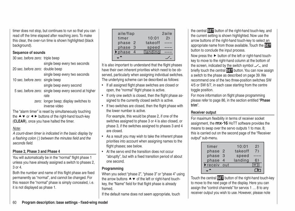
60 Program description: base settings - fi xed-wing model
timer does not stop, but continues to run so that you can read off the time elapsed after reaching zero. To make this clear, the over-run time is shown highlighted (black background).
Sequence of sounds30 sec. before zero: triple beep single beep every two seconds20 sec. before zero: double beep single beep every two seconds10 sec. before zero: single beep single beep every second 5 sec. before zero: single beep every second at higher
ratezero: longer beep; display switches to
inverse videoThe “alarm timer” is reset by simultaneously touching the or buttons of the right-hand touch-key (CLEAR), once you have halted the timer.
Note:A count-down timer is indicated in the basic display by a fl ashing colon (:) between the minutes fi eld and the seconds fi eld.
Phase 2, Phase 3 and Phase 4You will automatically be in the “normal” fl ight phase 1 unless you have already assigned a switch to phases 2, 3 or 4.Both the number and name of this fl ight phase are fi xed permanently as “normal”, and cannot be changed. For this reason the “normal” phase is simply concealed, i. e. it is not displayed as phase 1.
10:01 2phase 2phase 3phase 4
takeoff
landingspeed
–––––––––
aile/flap 2ailetimer
It is also important to understand that the fl ight phases have their own inherent priorities which need to be ob-served, particularly when assigning individual switches. The underlying scheme can be described as follows:
If all assigned fl ight phase switches are closed or • open, the “normal” fl ight phase is active.If only one switch is closed, then the fl ight phase as-• signed to the currently closed switch is active.If two switches are closed, then the fl ight phase with • the lower number is active.For example, this would be phase 2, if one of the switches assigned to phase 3 or 4 is also closed, or phase 3, if the switches assigned to phases 3 and 4 are closed.As a result you may wish to take the inherent phase • priorities into account when assigning names to the fl ight phases; see below. At the servo end the transition does not occur • “abruptly”, but with a fi xed transition period of about one second.
ProgrammingWhen you select “phase 2”, “phase 3” or “phase 4” using the arrow buttons of the left or right-hand touch-key, the “Name” fi eld for that fl ight phase is already framed.If the default name does not seem appropriate, touch
the central SET button of the right-hand touch-key, and the current setting is shown highlighted. Now use the arrow buttons of the right-hand touch-key to select an appropriate name from those available. Touch the SET button to conclude the input process.Now press the button of the left or right-hand touch-key to move to the right-hand column at the bottom of the screen, indicated by the switch symbol , and briefl y touch the central SET button. You can now assign a switch to the phase as described on page 39. We recommend one of the two three-position switches SW 4/5 or SW 6/7, in each case starting from the centre toggle position.For more information on fl ight phase programming please refer to page 86, in the section entitled “Phase trim”.
Receiver outputFor maximum fl exibility in terms of receiver socket assignment, the mx-16 HoTT software provides the means to swap over the servo outputs 1 to max. 8; this is carried out on the second page of the “Receiver output” sub-menu.
10:01 2phase 2phase 3phase 4
takeoff
landingspeed –––
timer7
6receiv out
Touch the central SET button of the right-hand touch-key to move to the next page of the display. Here you can assign the “control channels” for servos 1 … 8 to any receiver output you wish to use. However, please note
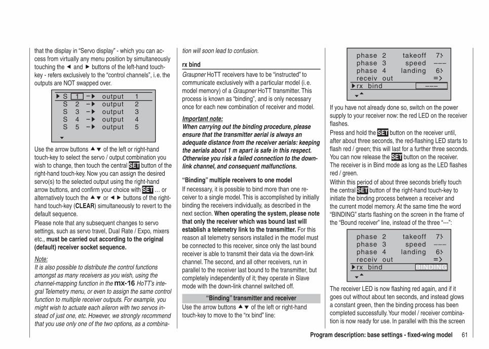
61Program description: base settings - fi xed-wing model
that the display in “Servo display” - which you can ac-cess from virtually any menu position by simultaneously touching the and buttons of the left-hand touch-key - refers exclusively to the “control channels”, i. e. the outputs are NOT swapped over.
SSSS
1234
1234
output
S 5 5
outputoutputoutputoutput
Use the arrow buttons of the left or right-hand touch-key to select the servo / output combination you wish to change, then touch the central SET button of the right-hand touch-key. Now you can assign the desired servo(s) to the selected output using the right-hand arrow buttons, and confi rm your choice with SET … or alternatively touch the or buttons of the right-hand touch-key (CLEAR) simultaneously to revert to the default sequence.Please note that any subsequent changes to servo settings, such as servo travel, Dual Rate / Expo, mixers etc., must be carried out according to the original (default) receiver socket sequence.
Note:It is also possible to distribute the control functions amongst as many receivers as you wish, using the channel-mapping function in the mx-16 HoTT’s inte-gral Telemetry menu, or even to assign the same control function to multiple receiver outputs. For example, you might wish to actuate each aileron with two servos in-stead of just one, etc. However, we strongly recommend that you use only one of the two options, as a combina-
tion will soon lead to confusion.
rx bindGraupner HoTT receivers have to be “instructed” to communicate exclusively with a particular model (i. e. model memory) of a Graupner HoTT transmitter. This process is known as “binding”, and is only necessary once for each new combination of receiver and model.
Important note:When carrying out the binding procedure, please ensure that the transmitter aerial is always an adequate distance from the receiver aerials: keeping the aerials about 1 m apart is safe in this respect. Otherwise you risk a failed connection to the down-link channel, and consequent malfunctions.
“Binding” multiple receivers to one modelIf necessary, it is possible to bind more than one re-ceiver to a single model. This is accomplished by initially binding the receivers individually, as described in the next section. When operating the system, please note that only the receiver which was bound last will establish a telemetry link to the transmitter. For this reason all telemetry sensors installed in the model must be connected to this receiver, since only the last bound receiver is able to transmit their data via the down-link channel. The second, and all other receivers, run in parallel to the receiver last bound to the transmitter, but completely independently of it; they operate in Slave mode with the down-link channel switched off.
“Binding” transmitter and receiverUse the arrow buttons of the left or right-hand touch-key to move to the “rx bind” line:
phase 2phase 3phase 4
takeoff
landingspeed –––
7
6receiv outrx bind –––
If you have not already done so, switch on the power supply to your receiver now: the red LED on the receiver flashes. Press and hold the SET button on the receiver until, after about three seconds, the red-flashing LED starts to flash red / green; this will last for a further three seconds. You can now release the SET button on the receiver. The receiver is in Bind mode as long as the LED flashes red / green.Within this period of about three seconds briefly touch the central SET button of the right-hand touch-key to initiate the binding process between a receiver and the current model memory. At the same time the word “BINDING” starts flashing on the screen in the frame of the “Bound receiver” line, instead of the three “---”:
phase 2phase 3phase 4
takeoff
landingspeed –––
7
6receiv outrx bind BINDING
The receiver LED is now fl ashing red again, and if it goes out without about ten seconds, and instead glows a constant green, then the binding process has been completed successfully. Your model / receiver combina-tion is now ready for use. In parallel with this the screen
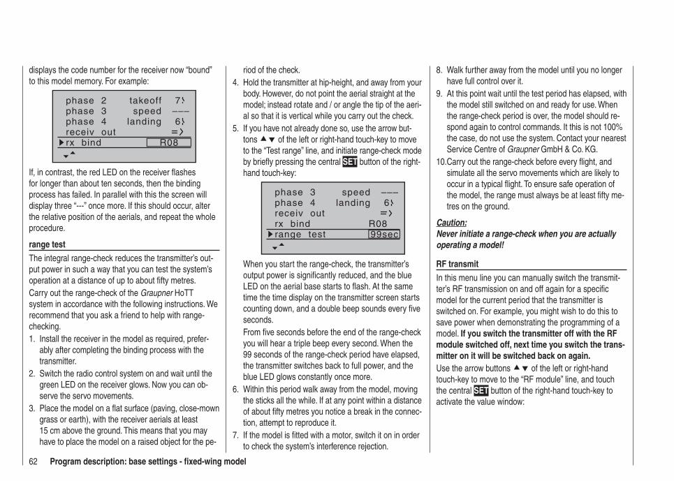
62 Program description: base settings - fi xed-wing model
displays the code number for the receiver now “bound” to this model memory. For example:
phase 2phase 3phase 4
takeoff
landingspeed –––
7
6receiv outrx bind R08
If, in contrast, the red LED on the receiver fl ashes for longer than about ten seconds, then the binding process has failed. In parallel with this the screen will display three “---” once more. If this should occur, alter the relative position of the aerials, and repeat the whole procedure.
range testThe integral range-check reduces the transmitter’s out-put power in such a way that you can test the system’s operation at a distance of up to about fi fty metres. Carry out the range-check of the Graupner HoTT system in accordance with the following instructions. We recommend that you ask a friend to help with range-checking.
Install the receiver in the model as required, prefer-1. ably after completing the binding process with the transmitter.Switch the radio control system on and wait until the 2. green LED on the receiver glows. Now you can ob-serve the servo movements.Place the model on a fl at surface (paving, close-mown 3. grass or earth), with the receiver aerials at least 15 cm above the ground. This means that you may have to place the model on a raised object for the pe-
riod of the check.Hold the transmitter at hip-height, and away from your 4. body. However, do not point the aerial straight at the model; instead rotate and / or angle the tip of the aeri-al so that it is vertical while you carry out the check.If you have not already done so, use the arrow but-5. tons of the left or right-hand touch-key to move to the “Test range” line, and initiate range-check mode by briefl y pressing the central SET button of the right-hand touch-key:
phase 3phase 4 landing
speed –––6
receiv outrx bind R08range test 99sec
When you start the range-check, the transmitter’s output power is signifi cantly reduced, and the blue LED on the aerial base starts to fl ash. At the same time the time display on the transmitter screen starts counting down, and a double beep sounds every fi ve seconds.From fi ve seconds before the end of the range-check you will hear a triple beep every second. When the 99 seconds of the range-check period have elapsed, the transmitter switches back to full power, and the blue LED glows constantly once more.Within this period walk away from the model, moving 6. the sticks all the while. If at any point within a distance of about fi fty metres you notice a break in the connec-tion, attempt to reproduce it.If the model is fi tted with a motor, switch it on in order 7. to check the system’s interference rejection.
Walk further away from the model until you no longer 8. have full control over it.At this point wait until the test period has elapsed, with 9. the model still switched on and ready for use. When the range-check period is over, the model should re-spond again to control commands. It this is not 100% the case, do not use the system. Contact your nearest Service Centre of Graupner GmbH & Co. KG.Carry out the range-check before every fl ight, and 10. simulate all the servo movements which are likely to occur in a typical fl ight. To ensure safe operation of the model, the range must always be at least fi fty me-tres on the ground.
Caution:Never initiate a range-check when you are actually operating a model!
RF transmitIn this menu line you can manually switch the transmit-ter’s RF transmission on and off again for a specifi c model for the current period that the transmitter is switched on. For example, you might wish to do this to save power when demonstrating the programming of a model. If you switch the transmitter off with the RF module switched off, next time you switch the trans-mitter on it will be switched back on again.Use the arrow buttons of the left or right-hand touch-key to move to the “RF module” line, and touch the central SET button of the right-hand touch-key to activate the value window:

63Program description: base settings - fi xed-wing model
phase 4 landing 6receiv outrx bind R08range test 99secRF transmit OFF
Now you can use the right-hand arrow buttons to switch between OFF and ON. Touch the central SET button of the right-hand touch-key again to conclude the input.
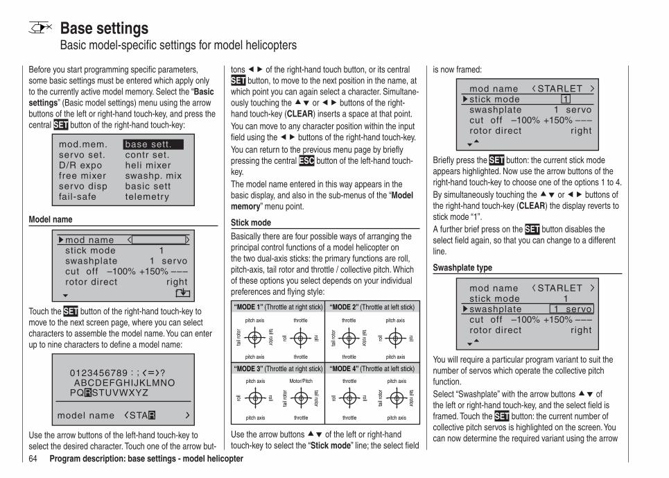
64 Program description: base settings - model helicopter
Base settingsBasic model-specifi c settings for model helicopters
Before you start programming specifi c parameters, some basic settings must be entered which apply only to the currently active model memory. Select the “Basic settings” (Basic model settings) menu using the arrow buttons of the left or right-hand touch-key, and press the central SET button of the right-hand touch-key:
mod.mem.servo set.D/R expofree mixer
contr set.heli mixerswashp. mix
servo disp basic settfail-safe telemetry
base sett.
Model name
mod namestick mode
rotor direct
swashplate1
right
1 servocut off –––+150%–100%
Touch the SET button of the right-hand touch-key to move to the next screen page, where you can select characters to assemble the model name. You can enter up to nine characters to defi ne a model name:
0123456789
model name
?: ;ABCDEFGHIJKLMNO
STAR
PQRSTUVWXYZ
Use the arrow buttons of the left-hand touch-key to select the desired character. Touch one of the arrow but-
tons of the right-hand touch button, or its central SET button, to move to the next position in the name, at which point you can again select a character. Simultane-ously touching the or buttons of the right-hand touch-key (CLEAR) inserts a space at that point.You can move to any character position within the input fi eld using the buttons of the right-hand touch-key.You can return to the previous menu page by briefl y pressing the central ESC button of the left-hand touch-key.The model name entered in this way appears in the basic display, and also in the sub-menus of the “Model memory” menu point.
Stick modeBasically there are four possible ways of arranging the principal control functions of a model helicopter on the two dual-axis sticks: the primary functions are roll, pitch-axis, tail rotor and throttle / collective pitch. Which of these options you select depends on your individual preferences and fl ying style:
“MODE 2” (Throttle at left stick)
“MODE 3” (Throttle at right stick) “MODE 4” (Throttle at left stick)
“MODE 1” (Throttle at right stick)
pitch axis
tail
roto
r
pitch axis
tail rotor
throttle
roll roll
throttle
tail
roto
r tail rotor
throttle throttle
pitch axis
pitch axis
roll roll
pitch axis
pitch axis
roll roll
Motor/Pitch
throttle
tail
roto
r tail rotor
throttle
throttle
roll roll
pitch axis
pitch axis
tail
roto
r tail rotor
Use the arrow buttons of the left or right-hand touch-key to select the “Stick mode” line; the select fi eld
is now framed:
mod namestick mode
rotor direct
swashplate1
right
1 servocut off –––+150%–100%
STARLET
Briefl y press the SET button: the current stick mode appears highlighted. Now use the arrow buttons of the right-hand touch-key to choose one of the options 1 to 4.By simultaneously touching the or buttons of the right-hand touch-key (CLEAR) the display reverts to stick mode “1”.A further brief press on the SET button disables the select fi eld again, so that you can change to a different line.
Swashplate type
mod namestick mode
rotor direct
swashplate1
right
1 servocut off –––+150%–100%
STARLET
You will require a particular program variant to suit the number of servos which operate the collective pitch function. Select “Swashplate” with the arrow buttons of the left or right-hand touch-key, and the select fi eld is framed. Touch the SET button: the current number of collective pitch servos is highlighted on the screen. You can now determine the required variant using the arrow
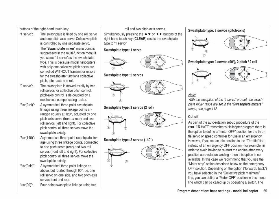
65Program description: base settings - model helicopter
buttons of the right-hand touch-key:“1 servo”: The swashplate is tilted by one roll servo
and one pitch-axis servo. Collective pitch is controlled by one separate servo.
The “Swashplate mixer” menu point is suppressed in the multi-function menu if you select “1 servo” as the swashplate type. This is because model helicopters with only one collective pitch servo are controlled WITHOUT transmitter mixers for the swashplate functions collective pitch, pitch-axis and roll.
“2 servo”: The swashplate is moved axially by two roll servos for collective pitch control; pitch-axis control is de-coupled by a mechanical compensating rocker.
“3sv(2rol)”: A symmetrical three-point swashplate linkage using three linkage points ar-ranged equally at 120°, actuated by one pitch-axis servo (front or rear) and two roll servos (left and right). For collective pitch control all three servos move the swashplate axially.
“3sv(140)”: Asymmetrical three-point swashplate link-age using three linkage points, connected to one pitch servo (rear) and two roll servos (front left and right). For collective pitch control all three servos move the swashplate axially.
“3sv(2nic)”: A symmetrical three-point linkage as above, but rotated through 90°, i. e. one roll servo on one side, and two pitch-axis servos front and rear.
“4sv(90)”: Four-point swashplate linkage using two
roll and two pitch-axis servos.Simultaneously pressing the or buttons of the right-hand touch-key (CLEAR) resets the swashplate type to “1 servo”.
Swashplate type: 1 servo
2
Swashplate type: 2 servos
2
1
Swashplate type: 3 servos (2 roll)
3
1
2
Swashplate type: 3 servos (140°)
3
1
2
Swashplate type: 3 servos (pitch-axis)
3
2
1
Swashplate type: 4 servos (90°), 2 pitch / 2 roll
25
1
3
Note:With the exception of the “1 servo” pre-set, the swash-plate mixer ratios are set in the “Swashplate mixers” menu; see page 112.
Cut offAs part of the auto-rotation set-up procedure of the mx-16 HoTT transmitter’s Helicopter program there is the option to defi ne a “motor OFF” position for the throt-tle servo or speed controller for use in an emergency. However, if you set an idle position in the “Throttle” line instead of an emergency OFF position - for example, in order to avoid having to re-start the engine after every practice auto-rotation landing - then this option is not available. In this case we recommend that you use the “Motor stop” option described below as the emergency OFF solution. Depending on the option (“forward / back”) you have selected in the “Collective pitch minimum” line, you can defi ne a “Motor OFF” position in this menu line which can be called up by operating a switch. The
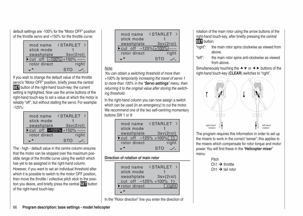
66 Program description: base settings - model helicopter
mod namestick mode
rotor direct
swashplate1
right
3sv(2rol)cut off –––
STARLET
STO
–125% +100%
Note:You can obtain a switching threshold of more than +100% by temporarily increasing the travel of servo 1 to more than 100% in the “Servo settings” menu, then returning it to the original value after storing the switch-ing threshold.
In the right-hand column you can now assign a switch which can be used (in an emergency) to cut the motor. We recommend one of the two self-centring momentary buttons SW 1 or 9:
mod namestick mode
rotor direct
swashplate1
right
3sv(2rol)cut off
STARLET
STO
–125% +100% 1
Direction of rotation of main rotor
mod namestick mode
rotor direct
swashplate1
right
3sv(2rol)cut off
STARLET
–125% +100% 1
In the “Rotor direction” line you enter the direction of
rotation of the main rotor using the arrow buttons of the right-hand touch-key, after briefl y pressing the central SET button:“right”: the main rotor spins clockwise as viewed from
above.“left”: the main rotor spins anti-clockwise as viewed
from above.Simultaneously touching the or buttons of the right-hand touch-key (CLEAR) switches to “right”.
right-hand rotation
left-hand rotation
The program requires this information in order to set up the mixers to work in the correct “sense”; this applies to the mixers which compensate for rotor torque and motor power. You will fi nd these in the “Helicopter mixer” menu: Pitch Ch1 throttle Ch1 tail rotor
default settings are -100% for the “Motor OFF” position of the throttle servo and +150% for the throttle curve:
mod namestick mode
rotor direct
swashplate1
right
3sv(2rol)cut off –––+150%–100%
STARLET
STO
If you wish to change the default value of the throttle servo’s “Motor OFF” position, briefl y press the central SET button of the right-hand touch-key: the current setting is highlighted. Now use the arrow buttons of the right-hand touch-key to set a value at which the motor is reliably “off”, but without stalling the servo. For example: -125%:
mod namestick mode
rotor direct
swashplate1
right
3sv(2rol)cut off –––+150%
STARLET
STO
–125%
The - high - default value in the centre column ensures that the motor can be stopped over the maximum pos-sible range of the throttle curve using the switch which has yet to be assigned in the right-hand column.However, if you want to set an individual threshold after which it is possible to switch to the motor OFF position, then move the throttle / collective pitch stick to the posi-tion you desire, and briefl y press the central SET button of the right-hand touch-key:

67Program description: base settings - model helicopter
Collective pitch min.
stick mode
rotor direct
swashplate1
right
3sv(2rol)cut off –125% +100% 1
pitch min rear
In the “Collective pitch min.” line you can set up the direction of operation of the throttle / collective pitch stick to suit your preference. This setting is crucial to the correct operation of all the other options in the helicopter program which affect the throttle and collective pitch functions, i. e. the throttle curve, idle trim, tail rotor mixer etc.Briefl y touch the central SET button of the right-hand touch-key, and the direction of operation of the throttle / collective pitch stick is highlighted. Now you can select the required variant using the arrow buttons of the right-hand touch-key:
Pitch
The meaning is as follows:“front”: minimum collective pitch when the collective
pitch stick (Ch 1) is “forward” (away from you);
“rear”: minimum collective pitch when the collective pitch stick (Ch 1) is “back” (towards you).
Simultaneously pressing the or buttons of the right-hand touch-key (CLEAR) returns the collective pitch min. position to “rear”.
Note:The Ch 1 trim always affects the throttle servo only.• By default what is known as the “throttle limiter” is set • (see page 79); this limits the travel of the throttle ser-vo in the direction of maximum throttle, acting sepa-rately from the collective pitch servos. This point can be programmed using the “Lim” input in the “Trans-mitter control settings” menu.
TimersTwo timers are shown in the basic display: one stop-watch and one fl ight timer.
STARLET#02
0:00h
stop flt
0:000:00
0.0V6.1V HoTT
M99%
A physical switch or a control switch - e. g. the control switch G3 located on the throttle limiter - can be as-signed to these two timers in the “Timers” line …
rotor direct
swashplate
right
3sv(2rol)cut off –125% +100% 1
pitch min reartimer 0:00 –––
… using the switch symbol at the bottom right-hand side of the screen. The assigned switch starts both tim-ers, and also halts the stopwatch.The method of assigning a physical switch or a control switch is described on page 39.The fl ight timer, and the saving of telemetry data on a memory card inserted in the card slot (see page 22) always starts simultaneously with the stopwatch, but continues to run even when the stopwatch is halted (switched off). It can only be stopped by touching the central ESC button of the left-hand touch-key with the stopwatch halted.Once stopped, both timers can be reset to the initial value by simultaneously touching the buttons of the right-hand touch-key (CLEAR).
Switching between “count-up” and “count-down”
Count-up timer (stopwatch function)If you assign a switch and start the stopwatch with the initial value of “0:00”, the timer runs up until the maxi-mum of 180 minutes and 59 seconds, then re-starts at 0:00.
Count-down timer (timer function)In the left-hand minutes fi eld you can select a starting time within the range 0 to 180 minutes; in the right-hand seconds fi eld the range is 0 to 59 seconds. Any combi-nation of times can also be selected.Simultaneously pressing the buttons of the right-hand touch-key (CLEAR) resets any settings you have entered to “0” or “00”.

68 Program description: base settings - model helicopter
rotor direct
swashplate
right
3sv(2rol)cut off –125% +100% 1
pitch min reartimer 10:01 G3
ProcedureSelect the desired input fi eld using the arrow buttons 1.
of the left or right-hand touch-key.Touch 2. SET in the centre of the right-hand touch-key.Select the required time in the highlighted minutes 3. and seconds fi elds using the arrow buttons of the right-hand touch-key.Touch the central 4. SET button to conclude the input process.Switch back to the basic display by repeatedly touch-5. ing the central ESC button of the left-hand touch-key. With the stopwatch halted, press the buttons of the right-hand touch-key simultaneously (CLEAR) to switch the stopwatch to the “Timer” function; see top right in the next illustration:
STARLET#02
0:00h
stop flt
10:010:00
0.0V6.1V HoTT
M99%
If you now operate the assigned switch, the stopwatch starts from the set initial value, counting down (“Timer function”). When the set time has elapsed, the timer does not stop, but continues to run to allow you to read
off the time elapsed after reaching zero. To make this clear, the over-run time is shown highlighted (black background).
Sequence of sounds30 sec. before zero: triple beep single beep every two seconds20 sec. before zero: double beep single beep every two seconds10 sec. before zero: single beep single beep every second 5 sec. before zero: single beep every second at higher
ratezero: longer beep; display switches to
inverse videoThe “alarm timer” is reset by simultaneously pressing the or buttons of the right-hand touch-key (CLEAR) after you have halted the timer.
Note:A count-down timer is indicated in the basic display by a fl ashing colon (:) between the minutes fi eld and the seconds fi eld.
Phase 2 / Phase 3You will automatically be in the “normal” fl ight phase 1 unless you have already assigned a switch to phases 2 or 3.Both the number and name of this fl ight phase are fi xed permanently as “normal”, and cannot be changed. For this reason the “normal” phase is simply concealed, i. e. it is not displayed as phase 1.
10:01 G3phase 2phase 3
hoverspeed
––––––
rotor direct r ightpitch min reartimer
It is also important to understand that the fl ight phases have their own inherent priorities which need to be ob-served, particularly when assigning individual switches. The underlying scheme can be described as follows:
If all assigned fl ight phase switches are closed or • open, the “normal” fl ight phase is active.If only one switch is closed, then the fl ight phase as-• signed to the currently closed switch is active.If two switches are closed, then the fl ight phase with • the lower number is active.For example, this would be phase 2 if the switches assigned to phase 2 and 3 are closed.The “auto-rotation phase” ALWAYS has precedence • over all other fl ight phases, regardless of the priori-ties outlined above. When the auto-rotation phase is selected, the switch is always made WITHOUT DELAY.With this in mind, you may wish to take the inherent • phase priorities into account when assigning names to the fl ight phases; see below.At the servo end the transition does not occur • “abruptly”, but with a fi xed transition period of about one second.
ProgrammingWhen you select “Phase 2” or “Phase 3” using the arrow buttons of the left or right-hand touch-key, the

69Program description: base settings - model helicopter
“Name” fi eld for that fl ight phase is already framed.If the default name does not seem appropriate, touch the central SET button of the right-hand touch-key, and the current setting is shown highlighted. Now use the arrow buttons of the right-hand touch-key to select an appropriate name from those available. Touch the SET button to conclude the input process.Now press the button of the left or right-hand touch-key to move to the right-hand column at the bottom of the screen, indicated by the switch symbol , and briefl y touch the central SET button. You can now assign a switch to the phase as described on page 39. We recommend one of the two three-position switches SW 4/5 or SW 6/7, in each case starting from the centre toggle position.For more information on fl ight phase programming please refer to page 94, in the section entitled “Flight phase specifi c settings for collective pitch, throttle and tail rotor”.
Auto-rotation
10:01 G3phase 2phase 3
hoverspeed
–––
pitch min reartimer
54
autorotat.
The name “Auto-rotation” is permanently assigned to Phase 4, and CANNOT be altered. The only available option is to assign a switch to it using the switch symbol at the right of the screen.For more information on programming fl ight phases please refer to the “Helicopter mixers” section starting
servo(s) to the selected output using the right-hand arrow buttons, and confi rm your choice with SET … or alternatively touch the or buttons of the right-hand touch-key (CLEAR) simultaneously to revert to the default sequence.Please note that any subsequent changes to servo settings, such as servo travel, Dual Rate / Expo, mixers etc., must be carried out according to the original (default) receiver socket sequence.
Typical application:In the helicopter program of the mx-16 HoTT the outputs for one collective pitch servo and the throttle servo have been interchanged compared to all earlier GRAUPNER/JR mc-systems. The throttle servo is now assigned to receiver output “6” and the collective pitch servo to output “1”. However, you may wish to retain the earlier confi guration.
SSSS
6234
1234
output
S 5 5S 61
outputoutputoutputoutputoutput
Note:It is also possible to distribute the control functions amongst as many receivers as you wish, using the channel-mapping function in the mx-16 HoTT’s integral Telemetry menu, or even to assign the same control function to multiple receiver outputs. However, we strongly recommend that you use only one of the two options, as a combination will soon lead to confusion.
on page 94.
Receiver outputFor maximum fl exibility in terms of receiver socket assignment, the mx-16 HoTT software provides the means to swap over the servo outputs 1 to max. 8; this is carried out on the second page of the “Receiver output” sub-menu.
10:01 G3phase 2phase 3
hoverspeed
timer54
autorotat. 2receiv out
Touch the central SET button of the right-hand touch-key to move to the next page of the display. Here you can assign the “control channels” for servos 1 … 8 to any receiver output you wish to use. However, please note that the display in “Servo display” - which you can ac-cess from virtually any menu position by simultaneously touching the and buttons of the left-hand touch-key - refers exclusively to the “control channels”, i. e. the outputs are NOT swapped over.
SSSS
1234
1234
output
S 5 5
outputoutputoutputoutput
Use the arrow buttons of the left or right-hand touch-key to select the servo / output combination you wish to change, then touch the central SET button of the right-hand touch-key. Now you can assign the desired
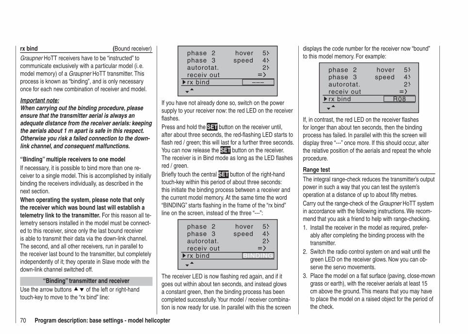
70 Program description: base settings - model helicopter
rx bind (Bound receiver)
Graupner HoTT receivers have to be “instructed” to communicate exclusively with a particular model (i. e. model memory) of a Graupner HoTT transmitter. This process is known as “binding”, and is only necessary once for each new combination of receiver and model.
Important note:When carrying out the binding procedure, please ensure that the transmitter aerial is always an adequate distance from the receiver aerials: keeping the aerials about 1 m apart is safe in this respect. Otherwise you risk a failed connection to the down-link channel, and consequent malfunctions.
“Binding” multiple receivers to one modelIf necessary, it is possible to bind more than one re-ceiver to a single model. This is accomplished by initially binding the receivers individually, as described in the next section.When operating the system, please note that only the receiver which was bound last will establish a telemetry link to the transmitter. For this reason all te-lemetry sensors installed in the model must be connect-ed to this receiver, since only the last bound receiver is able to transmit their data via the down-link channel. The second, and all other receivers, run in parallel to the receiver last bound to the transmitter, but completely independently of it; they operate in Slave mode with the down-link channel switched off.
“Binding” transmitter and receiverUse the arrow buttons of the left or right-hand touch-key to move to the “rx bind” line:
phase 2phase 3
hoverspeed
54
autorotat. 2receiv outrx bind –––
If you have not already done so, switch on the power supply to your receiver now: the red LED on the receiver fl ashes.Press and hold the SET button on the receiver until, after about three seconds, the red-fl ashing LED starts to fl ash red / green; this will last for a further three seconds. You can now release the SET button on the receiver. The receiver is in Bind mode as long as the LED fl ashes red / green.Briefl y touch the central SET button of the right-hand touch-key within this period of about three seconds: this initiate the binding process between a receiver and the current model memory. At the same time the word “BINDING” starts fl ashing in the frame of the “rx bind” line on the screen, instead of the three “---”:
phase 2phase 3
hoverspeed
54
autorotat. 2receiv outrx bind BINDING
The receiver LED is now fl ashing red again, and if it goes out within about ten seconds, and instead glows a constant green, then the binding process has been completed successfully. Your model / receiver combina-tion is now ready for use. In parallel with this the screen
displays the code number for the receiver now “bound” to this model memory. For example:
phase 2phase 3
hoverspeed
54
autorotat. 2receiv outrx bind R08
If, in contrast, the red LED on the receiver fl ashes for longer than about ten seconds, then the binding process has failed. In parallel with this the screen will display three “---” once more. If this should occur, alter the relative position of the aerials and repeat the whole procedure.
Range testThe integral range-check reduces the transmitter’s output power in such a way that you can test the system’s operation at a distance of up to about fi fty metres.Carry out the range-check of the Graupner HoTT system in accordance with the following instructions. We recom-mend that you ask a friend to help with range-checking.
Install the receiver in the model as required, prefer-1. ably after completing the binding process with the transmitter.Switch the radio control system on and wait until the 2. green LED on the receiver glows. Now you can ob-serve the servo movements.Place the model on a fl at surface (paving, close-mown 3. grass or earth), with the receiver aerials at least 15 cm above the ground. This means that you may have to place the model on a raised object for the period of the check.
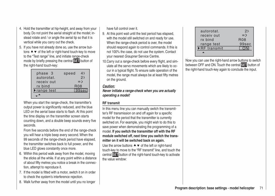
71Program description: base settings - model helicopter
Hold the transmitter at hip-height, and away from your 4. body. Do not point the aerial straight at the model; in-stead rotate and / or angle the aerial tip so that it is vertical while you carry out the check.If you have not already done so, use the arrow but-5. tons of the left or right-hand touch-key to move to the “Test range” line, and initiate range-check mode by briefl y pressing the central SET button of the right-hand touch-key:
phase 3 speed 4autorotat. 2receiv outrx bind R08range test 99sec
When you start the range-check, the transmitter’s output power is signifi cantly reduced, and the blue LED on the aerial base starts to fl ash. At this point the time display on the transmitter screen starts counting down, and a double beep sounds every fi ve seconds.From fi ve seconds before the end of the range-check you will hear a triple beep every second. When the 99 seconds of the range-check period have elapsed, the transmitter switches back to full power, and the blue LED glows constantly once more.Within this period walk away from the model, moving 6. the sticks all the while. If at any point within a distance of about fi fty metres you notice a break in the connec-tion, attempt to reproduce it.If the model is fi tted with a motor, switch it on in order 7. to check the system’s interference rejection.Walk further away from the model until you no longer 8.
have full control over it.At this point wait until the test period has elapsed, 9. with the model still switched on and ready for use. When the range-check period is over, the model should respond again to control commands. It this is not 100% the case, do not use the system. Contact your nearest Graupner Service Centre.Carry out a range-check before every fl ight, and sim-10. ulate all the servo movements which are likely to oc-cur in a typical fl ight. To ensure safe operation of the model, the range must always be at least fi fty metres on the ground.
Caution:Never initiate a range-check when you are actually operating a model!
RF transmitIn this menu line you can manually switch the transmit-ter’s RF transmission on and off again for a specifi c model for the period that the transmitter is currently switched on. For example, you might wish to do this to save power when demonstrating the programming of a model. If you switch the transmitter off with the RF module switched off, next time you switch the trans-mitter on it will be switched back on again.Use the arrow buttons of the left or right-hand touch-key to move to the “RF transmit” line, and touch the central SET button of the right-hand touch-key to activate the value window:
autorotat. 2receiv outrx bind R08range test 99secRF transmit ON
Now you can use the right-hand arrow buttons to switch between OFF and ON. Touch the central SET button of the right-hand touch-key again to conclude the input.

72 Program description: servo settings
Column 3 “Centre”The facility to offset the servo travel centre is intended for adjusting servos whose centre setting is not standard (servo centre point at 1.5 ms or 1500 µs), and also for minor adjustments, e. g. when fi ne-tuning the neutral position of the model’s control surfaces.The neutral position can be shifted over the range -125% to +125% of normal servo travel, within the maximum servo travel of +/- 150%, regardless of the trim lever position and any mixers you have set up. The setting affects the associated servo directly, independ-ently of all other trim and mixer settings.However, please note that an extreme shift of the servo’s neutral point may result in servo travel to one side of neutral only, as total servo travel is limited to +/- 150% for both electronic and mechanical reasons.Simultaneously pressing the arrow buttons or of the right-hand touch-key (CLEAR) resets the value in the highlighted input fi eld to “0%”.
Servo travel
-125% Centre adjustment +125%
connected, assuming that these have not been swapped over. This means that changing the stick mode does not affect the numbering of the servos.
Column 2 “Rev.”The direction of servo rotation can be adjusted to suit the actual installation in your model. This means that you don’t need to concern yourself with servo directions when installing the mechanical linkages in the model, as you can reverse them as and when necessary. The direction of rotation is indicated by the symbols “=>” and “<=”. Be sure to set the direction of servo rotation before you make adjustments to the remaining options!Simultaneously pressing the arrow buttons or of the right-hand touch-key (CLEAR) resets the direction of rotation to “=>”.
normalreversed
normal
reversed
S1S2S3
rev cent +trav
0%0%0%
100% 100%100% 100%100% 100%
0%0%
100% 100%100% 100%
S4S5
In this menu you can adjust parameters which only af-fect the servo connected to a particular receiver output, namely the direction of servo rotation, neutral point and servo travel. Always start with the servo setting in the left-hand column.v
Basic procedure:Use the arrow buttons 1. of the left or right-hand touch-key to select the relevant servo (1 to 8).If necessary, use the arrow buttons 2. of the left or right-hand touch-key to select the desired column, and move the associated transmitter control from its centre position if you wish to defi ne an asymmetri-cal setting.Touch the central 3. SET button of the right-hand touch-key, and the corresponding input fi eld is highlighted (black background).Set the appropriate value using the arrow buttons of 4. the right-hand touch-key.Touch the central 5. SET button of the right-hand touch-key to conclude the input process.Simultaneously pressing the arrow buttons 6. or
of the right-hand touch-key (CLEAR) resets any settings you have entered to the default value.
Important:The numbers in the servo designations refer to the receiver output socket to which a particular servo(s) is
Servo settingsServo direction, centre, travel
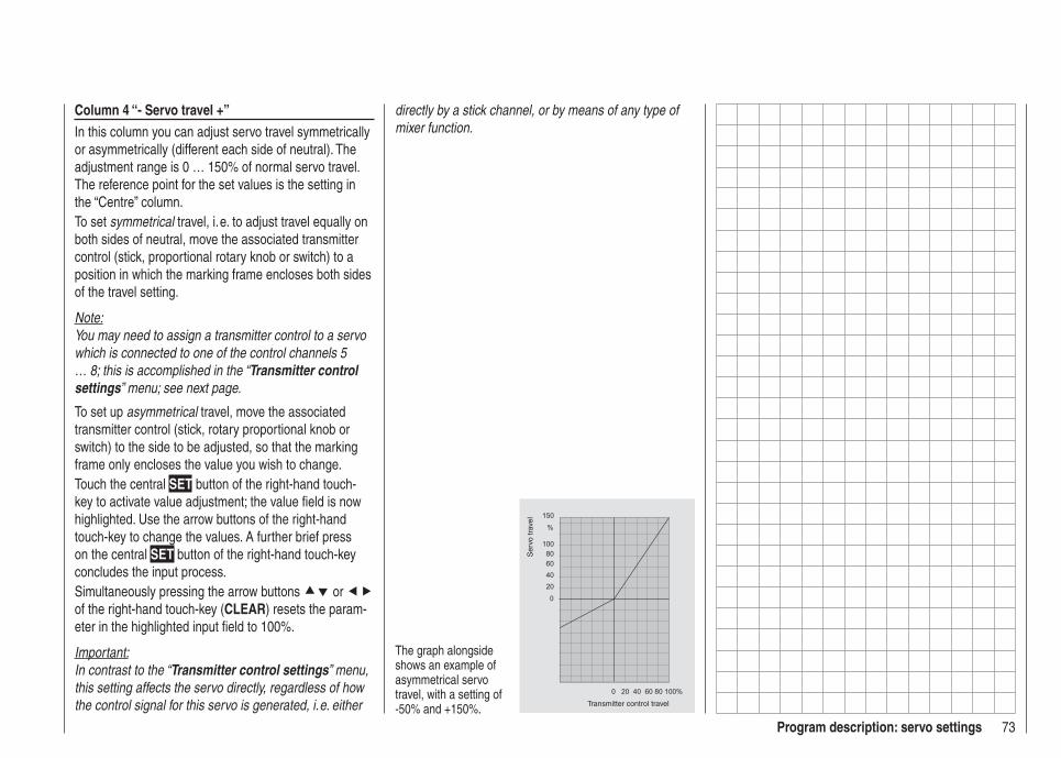
73Program description: servo settings
Column 4 “- Servo travel +”In this column you can adjust servo travel symmetrically or asymmetrically (different each side of neutral). The adjustment range is 0 … 150% of normal servo travel. The reference point for the set values is the setting in the “Centre” column.To set symmetrical travel, i. e. to adjust travel equally on both sides of neutral, move the associated transmitter control (stick, proportional rotary knob or switch) to a position in which the marking frame encloses both sides of the travel setting.
Note:You may need to assign a transmitter control to a servo which is connected to one of the control channels 5 … 8; this is accomplished in the “Transmitter control settings” menu; see next page.
To set up asymmetrical travel, move the associated transmitter control (stick, rotary proportional knob or switch) to the side to be adjusted, so that the marking frame only encloses the value you wish to change.Touch the central SET button of the right-hand touch-key to activate value adjustment; the value fi eld is now highlighted. Use the arrow buttons of the right-hand touch-key to change the values. A further brief press on the central SET button of the right-hand touch-key concludes the input process.Simultaneously pressing the arrow buttons or of the right-hand touch-key (CLEAR) resets the param-eter in the highlighted input fi eld to 100%.
Important:In contrast to the “Transmitter control settings” menu, this setting affects the servo directly, regardless of how the control signal for this servo is generated, i. e. either
The graph alongside shows an example of asymmetrical servo travel, with a setting of -50% and +150%. Transmitter control travel
Ser
vo tr
avel
directly by a stick channel, or by means of any type of mixer function.
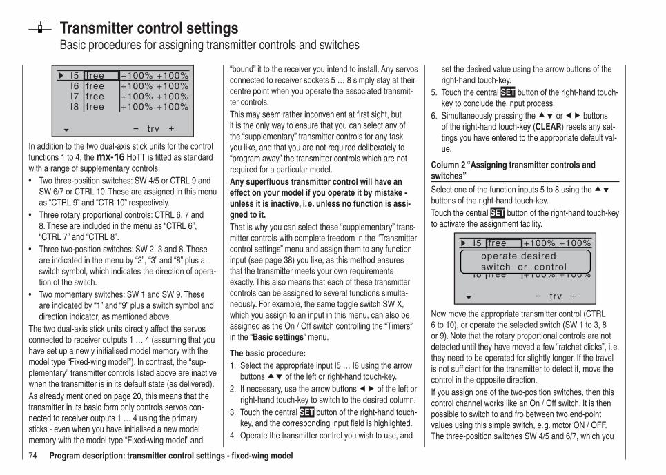
74 Program description: transmitter control settings - fi xed-wing model
Transmitter control settingsBasic procedures for assigning transmitter controls and switches
I5I6I7
+trv
+100% +100%+100% +100%+100% +100%
free
I8 +100% +100%
freefreefree
In addition to the two dual-axis stick units for the control functions 1 to 4, the mx-16 HoTT is fi tted as standard with a range of supplementary controls:
Two three-position switches: SW 4/5 or CTRL 9 and • SW 6/7 or CTRL 10. These are assigned in this menu as “CTRL 9” and “CTR 10” respectively.Three rotary proportional controls: CTRL 6, 7 and • 8. These are included in the menu as “CTRL 6”, “CTRL 7” and “CTRL 8”.Three two-position switches: SW 2, 3 and 8. These • are indicated in the menu by “2”, “3” and “8” plus a switch symbol, which indicates the direction of opera-tion of the switch.Two momentary switches: SW 1 and SW 9. These • are indicated by “1” and “9” plus a switch symbol and direction indicator, as mentioned above.
The two dual-axis stick units directly affect the servos connected to receiver outputs 1 … 4 (assuming that you have set up a newly initialised model memory with the model type “Fixed-wing model”). In contrast, the “sup-plementary” transmitter controls listed above are inactive when the transmitter is in its default state (as delivered).As already mentioned on page 20, this means that the transmitter in its basic form only controls servos con-nected to receiver outputs 1 … 4 using the primary sticks - even when you have initialised a new model memory with the model type “Fixed-wing model” and
“bound” it to the receiver you intend to install. Any servos connected to receiver sockets 5 … 8 simply stay at their centre point when you operate the associated transmit-ter controls.This may seem rather inconvenient at fi rst sight, but it is the only way to ensure that you can select any of the “supplementary” transmitter controls for any task you like, and that you are not required deliberately to “program away” the transmitter controls which are not required for a particular model.Any superfl uous transmitter control will have an effect on your model if you operate it by mistake - unless it is inactive, i. e. unless no function is assi-gned to it.That is why you can select these “supplementary” trans-mitter controls with complete freedom in the “Transmitter control settings” menu and assign them to any function input (see page 38) you like, as this method ensures that the transmitter meets your own requirements exactly. This also means that each of these transmitter controls can be assigned to several functions simulta-neously. For example, the same toggle switch SW X, which you assign to an input in this menu, can also be assigned as the On / Off switch controlling the “Timers” in the “Basic settings” menu.
The basic procedure:Select the appropriate input I5 … I8 using the arrow 1. buttons of the left or right-hand touch-key.If necessary, use the arrow buttons 2. of the left or right-hand touch-key to switch to the desired column.Touch the central 3. SET button of the right-hand touch-key, and the corresponding input fi eld is highlighted.Operate the transmitter control you wish to use, and 4.
set the desired value using the arrow buttons of the right-hand touch-key.Touch the central 5. SET button of the right-hand touch-key to conclude the input process.Simultaneously pressing the 6. or buttons of the right-hand touch-key (CLEAR) resets any set-tings you have entered to the appropriate default val-ue.
Column 2 “Assigning transmitter controls and switches”Select one of the function inputs 5 to 8 using the buttons of the right-hand touch-key.Touch the central SET button of the right-hand touch-key to activate the assignment facility.
I5
+trv
free
I8 free
+100% +100%
+100% +100%
operate desiredswitch or control
Now move the appropriate transmitter control (CTRL 6 to 10), or operate the selected switch (SW 1 to 3, 8 or 9). Note that the rotary proportional controls are not detected until they have moved a few “ratchet clicks”, i. e. they need to be operated for slightly longer. If the travel is not suffi cient for the transmitter to detect it, move the control in the opposite direction.If you assign one of the two-position switches, then this control channel works like an On / Off switch. It is then possible to switch to and fro between two end-point values using this simple switch, e. g. motor ON / OFF. The three-position switches SW 4/5 and 6/7, which you
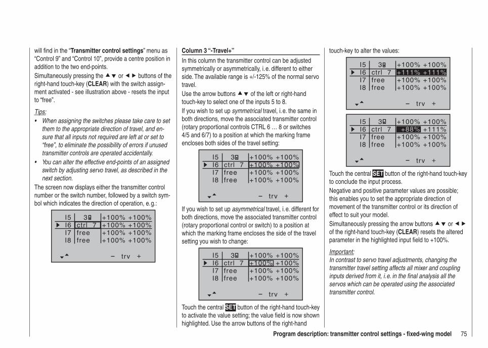
75Program description: transmitter control settings - fi xed-wing model
will fi nd in the “Transmitter control settings” menu as “Control 9” and “Control 10”, provide a centre position in addition to the two end-points.Simultaneously pressing the or buttons of the right-hand touch-key (CLEAR) with the switch assign-ment activated - see illustration above - resets the input to “free”.
Tips:When assigning the switches please take care to set • them to the appropriate direction of travel, and en-sure that all inputs not required are left at or set to “free”, to eliminate the possibility of errors if unused transmitter controls are operated accidentally.You can alter the effective end-points of an assigned • switch by adjusting servo travel, as described in the next section.
The screen now displays either the transmitter control number or the switch number, followed by a switch sym-bol which indicates the direction of operation, e. g.:
I5I6I7
+trv
I8
ctr l 7freefree
3 +100% +100%+100%
+100% +100%+100% +100%
+100%
Column 3 “-Travel+”In this column the transmitter control can be adjusted symmetrically or asymmetrically, i. e. different to either side. The available range is +/-125% of the normal servo travel.Use the arrow buttons of the left or right-hand touch-key to select one of the inputs 5 to 8.If you wish to set up symmetrical travel, i. e. the same in both directions, move the associated transmitter control (rotary proportional controls CTRL 6 … 8 or switches 4/5 and 6/7) to a position at which the marking frame encloses both sides of the travel setting:
I5I6I7
+trv
3
I8
ctr l 7freefree
+100% +100%+100% +100%+100% +100%+100% +100%
If you wish to set up asymmetrical travel, i. e. different for both directions, move the associated transmitter control (rotary proportional control or switch) to a position at which the marking frame encloses the side of the travel setting you wish to change:
I5I6I7
+trv
I8
ctr l 7freefree
3 +100% +100%+100% +100%+100% +100%+100% +100%
Touch the central SET button of the right-hand touch-key to activate the value setting; the value fi eld is now shown highlighted. Use the arrow buttons of the right-hand
touch-key to alter the values:
I5I6I7
+trv
I8
ctr l 7freefree
+111% +111%3 +100% +100%
+100% +100%+100% +100%
I5I6I7
+trv
+100% +100%
+100% +100%I8 +100% +100%
ctrl 7freefree
+88% +111%3
Touch the central SET button of the right-hand touch-key to conclude the input process.Negative and positive parameter values are possible; this enables you to set the appropriate direction of movement of the transmitter control or its direction of effect to suit your model.Simultaneously pressing the arrow buttons or of the right-hand touch-key (CLEAR) resets the altered parameter in the highlighted input fi eld to +100%.
Important:In contrast to servo travel adjustments, changing the transmitter travel setting affects all mixer and coupling inputs derived from it, i. e. in the fi nal analysis all the servos which can be operated using the associated transmitter control.

76 Program description: transmitter control settings – model helicopter
Transmitter control settingsBasic procedures for assigning transmitter controls and switches
+trv
freefreefreefreectr l 6
+100% +100%+100% +100%+100% +100%+100% +100%+100% +100%
I5thrgyr
I8lim
In addition to the two dual-axis stick units for the control functions 1 to 4, the mx-16 HoTT is fi tted as standard with a range of supplementary controls:
Two three-position switches: SW 4/5 or CTRL 9 and • SW 6/7 or CTRL 10. These are assigned in this menu as “CTRL 9” and “CTR 10” respectively.Three rotary proportional controls: CTRL 6, 7 and • 8. These are included in the menu as “Control 6”, “Control 7” and “Control 8”.Three two-position switches: SW 2, 3 and 8. These • are indicated in the menu by “2”, “3” and “8” plus a switch symbol, which indicates the direction of opera-tion of the switch.Two momentary switches: SW 1 and SW 9. These • are indicated by “1” and “9” plus a switch symbol and direction indicator, as mentioned above.
The two dual-axis stick units directly affect servos connected to receiver outputs 1 … 4 and 6 (assuming that you have set up a newly initialised model memory with the model type “Helicopter”). In contrast, the “sup-plementary” transmitter controls listed above are inactive when the transmitter is in its default state (as delivered). The exception is the rotary proportional knob CTRL 7 (throttle limiter), which acts upon servo 6 by default.As already mentioned on page 20, this means that the transmitter in its basic form only controls servos con-nected to receiver outputs 1 … 4 using the primary
sticks, plus servo 6 - depending on the position of the throttle limiter - even when you have initialised a new model memory with the model type “Helicopter” and “bound” it to the receiver you intend to install. Any ser-vos connected to receiver sockets 5, 7 and 8 simply stay at their centre point when you operate the associated transmitter controls.This may seem rather inconvenient at fi rst sight, but it is the only way to ensure that you can select any of the “supplementary” transmitter controls for any task you like, and that you are not required deliberately to “program away” the transmitter controls which are not required for a particular model.Any superfl uous transmitter control will have an effect on your model if you operate it by mistake, unless it is inactive, i. e. unless no function is assi-gned to it.That is why you can select these “supplementary” trans-mitter controls with complete freedom in the “Transmitter control settings” menu, and assign them to any function input (see page 38) you like, as this method ensures that the transmitter meets your own requirements exactly. This also means that each of these transmitter controls can be assigned to several functions simultane-ously. For example, the same toggle switch SW X which you assign to an input in this menu, can also be as-signed as the On / OFF switch controlling the “Timers” in the “Basic settings” menu.
Note:For model helicopters input 6 must always be left “free”. Please see the section entitled “Throttle” on the next double-page.
The basic procedureSelect the appropriate input I5, throttle, gyro, I8 or 1. Lim using the arrow buttons of the left or right-hand touch-key.If necessary, use the arrow buttons 2. of the left or right-hand touch-key to switch to the desired column.Touch the central 3. SET button of the right-hand touch-key, and the corresponding input fi eld is highlighted.Operate the transmitter control you wish to use, and 4. set the desired value using the arrow buttons of the right-hand touch-key.Touch the central 5. SET button of the right-hand touch-key to conclude the input process.Simultaneously pressing the 6. or buttons of the right-hand touch-key (CLEAR) resets any set-tings you have entered to the appropriate default val-ue.
Column 2 “Assigning transmitter controls and switches”Select one of the function inputs I5, throttle, gyro, I8 or lim using the buttons of the left or right-hand touch-key.Touch the central SET button of the right-hand touch-key to activate the assignment facility.
+trv
free
freectr l 6
I5
I8lim
+100% +100%
+100% +100%+100% +100%
operate desiredswitch or control
Now move the appropriate transmitter control (CTRL 6 to 10), or operate the selected switch (SW 1 to 3, 8
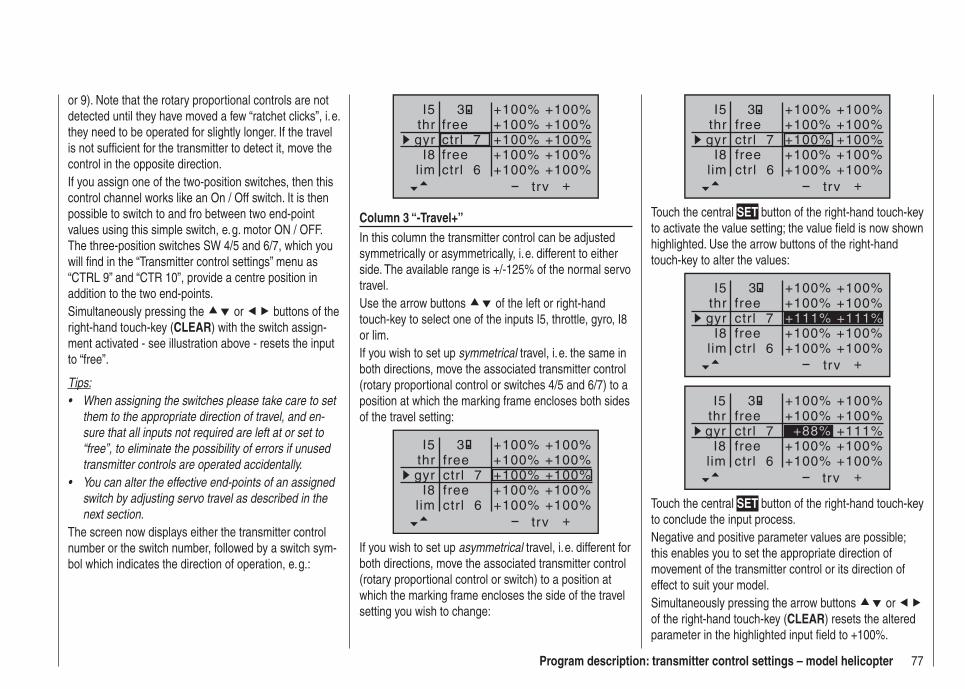
77Program description: transmitter control settings – model helicopter
+
3 +100% +100%+100% +100%+100% +100%+100% +100%+100% +100%
trv
free
freectr l 6
ctr l 7
I5thrgyr
I8lim
Touch the central SET button of the right-hand touch-key to activate the value setting; the value fi eld is now shown highlighted. Use the arrow buttons of the right-hand touch-key to alter the values:
+
+111% +111%
+100% +100%+100% +100%
+100% +100%+100% +100%
trv
free
freectr l 6
ctr l 7
I5thrgyr
I8lim
3
+
+88%
+100% +100%+100% +100%
+111%+100% +100%+100% +100%
trv
free
freectr l 6
ctr l 7
I5thrgyr
I8lim
3
Touch the central SET button of the right-hand touch-key to conclude the input process.Negative and positive parameter values are possible; this enables you to set the appropriate direction of movement of the transmitter control or its direction of effect to suit your model.Simultaneously pressing the arrow buttons or of the right-hand touch-key (CLEAR) resets the altered parameter in the highlighted input fi eld to +100%.
or 9). Note that the rotary proportional controls are not detected until they have moved a few “ratchet clicks”, i. e. they need to be operated for slightly longer. If the travel is not suffi cient for the transmitter to detect it, move the control in the opposite direction.If you assign one of the two-position switches, then this control channel works like an On / Off switch. It is then possible to switch to and fro between two end-point values using this simple switch, e. g. motor ON / OFF. The three-position switches SW 4/5 and 6/7, which you will fi nd in the “Transmitter control settings” menu as “CTRL 9” and “CTR 10”, provide a centre position in addition to the two end-points.Simultaneously pressing the or buttons of the right-hand touch-key (CLEAR) with the switch assign-ment activated - see illustration above - resets the input to “free”.
Tips:When assigning the switches please take care to set • them to the appropriate direction of travel, and en-sure that all inputs not required are left at or set to “free”, to eliminate the possibility of errors if unused transmitter controls are operated accidentally.You can alter the effective end-points of an assigned • switch by adjusting servo travel as described in the next section.
The screen now displays either the transmitter control number or the switch number, followed by a switch sym-bol which indicates the direction of operation, e. g.:
+trv
free
freectr l 6
ctr l 7
I5thrgyr
I8lim
3 +100% +100%+100% +100%+100% +100%+100% +100%+100% +100%
Column 3 “-Travel+”In this column the transmitter control can be adjusted symmetrically or asymmetrically, i. e. different to either side. The available range is +/-125% of the normal servo travel.Use the arrow buttons of the left or right-hand touch-key to select one of the inputs I5, throttle, gyro, I8 or lim.If you wish to set up symmetrical travel, i. e. the same in both directions, move the associated transmitter control (rotary proportional control or switches 4/5 and 6/7) to a position at which the marking frame encloses both sides of the travel setting:
+
3 +100% +100%+100% +100%+100% +100%+100% +100%+100% +100%
trv
free
freectr l 6
ctr l 7
I5thrgyr
I8lim
If you wish to set up asymmetrical travel, i. e. different for both directions, move the associated transmitter control (rotary proportional control or switch) to a position at which the marking frame encloses the side of the travel setting you wish to change:
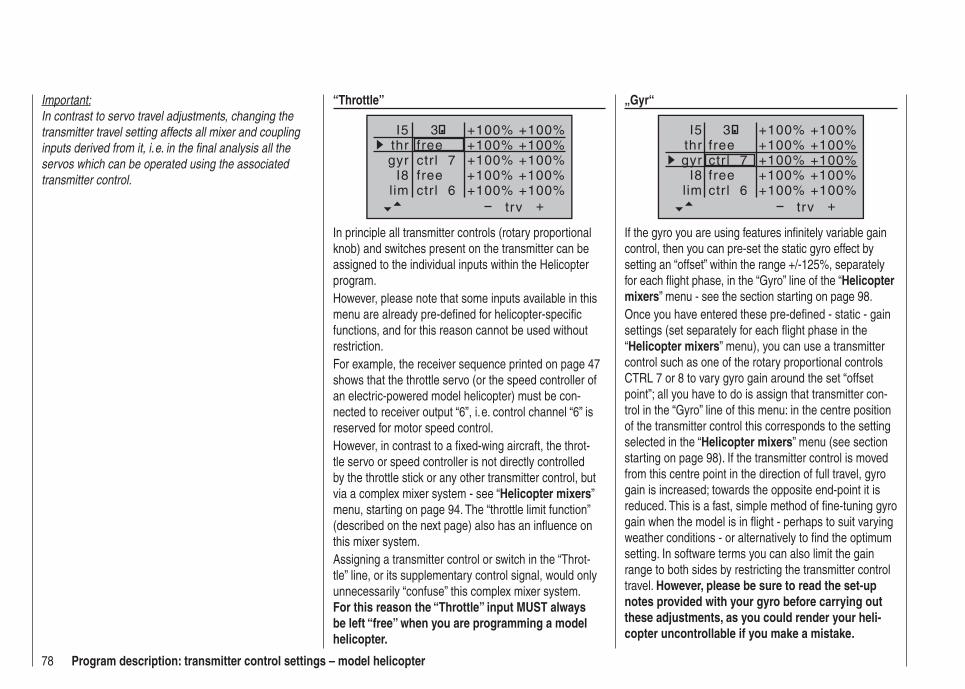
78 Program description: transmitter control settings – model helicopter
Important:In contrast to servo travel adjustments, changing the transmitter travel setting affects all mixer and coupling inputs derived from it, i. e. in the fi nal analysis all the servos which can be operated using the associated transmitter control.
“Throttle”
+
+100%
+100% +100%+100% +100%
+100%+100% +100%+100% +100%
trv
free
freectr l 6
ctr l 7
I5thrgyr
I8lim
3
In principle all transmitter controls (rotary proportional knob) and switches present on the transmitter can be assigned to the individual inputs within the Helicopter program.However, please note that some inputs available in this menu are already pre-defi ned for helicopter-specifi c functions, and for this reason cannot be used without restriction.For example, the receiver sequence printed on page 47 shows that the throttle servo (or the speed controller of an electric-powered model helicopter) must be con-nected to receiver output “6”, i. e. control channel “6” is reserved for motor speed control.However, in contrast to a fi xed-wing aircraft, the throt-tle servo or speed controller is not directly controlled by the throttle stick or any other transmitter control, but via a complex mixer system - see “Helicopter mixers” menu, starting on page 94. The “throttle limit function” (described on the next page) also has an infl uence on this mixer system.Assigning a transmitter control or switch in the “Throt-tle” line, or its supplementary control signal, would only unnecessarily “confuse” this complex mixer system. For this reason the “Throttle” input MUST always be left “free” when you are programming a model helicopter.
„Gyr“
+trv
I5thrgyr
I8lim
+100%
3 +100% +100%+100% +100%
+100%+100% +100%+100% +100%
free
freectr l 6
ctr l 7
If the gyro you are using features infi nitely variable gain control, then you can pre-set the static gyro effect by setting an “offset” within the range +/-125%, separately for each fl ight phase, in the “Gyro” line of the “Helicopter mixers” menu - see the section starting on page 98.Once you have entered these pre-defi ned - static - gain settings (set separately for each fl ight phase in the “Helicopter mixers” menu), you can use a transmitter control such as one of the rotary proportional controls CTRL 7 or 8 to vary gyro gain around the set “offset point”; all you have to do is assign that transmitter con-trol in the “Gyro” line of this menu: in the centre position of the transmitter control this corresponds to the setting selected in the “Helicopter mixers” menu (see section starting on page 98). If the transmitter control is moved from this centre point in the direction of full travel, gyro gain is increased; towards the opposite end-point it is reduced. This is a fast, simple method of fi ne-tuning gyro gain when the model is in fl ight - perhaps to suit varying weather conditions - or alternatively to fi nd the optimum setting. In software terms you can also limit the gain range to both sides by restricting the transmitter control travel. However, please be sure to read the set-up notes provided with your gyro before carrying out these adjustments, as you could render your heli-copter uncontrollable if you make a mistake.

79Program description: transmitter control settings – model helicopter
By default the “lim” input is assigned to the rotary pro-portional control CTRL 6, which is located at top left on the transmitter:
+
+100%
+100% +100%+100% +100%
+100%+100% +100%+100% +100%
trv
free
freectr l 6
ctr l 7
I5thrgyr
I8lim
3
This pre-defi ned assignment eliminates the need to program two fl ight phases - “with idle-up” and “without idle-up” - as are often used by other radio control sys-tems for this purpose, since the method of raising the system rotational speed below the hover point is more fl exible with the mx-16 HoTT program, and can be fi ne-tuned more accurately than using the conventional “idle-up” function. However, if you prefer to program your helicopter “with idle-up”, then switch off the “throttle limit” function, described below, by setting the “Lim” input to “free”.
Meaning and application of “throttle limit”As mentioned previously under “Throttle”, the power output of the engine or motor of a model helicopter is not controlled directly using the throttle (Ch 1) stick - in contrast to fi xed-wing model aircraft. Instead it is control-led indirectly by the throttle curve settings which you set up in the “Helicopter mixers” menu. Alternatively the throttle is controlled by the speed controller if the unit you are using is a governor or regulator.
Note:Naturally it is possible to set up different throttle curves to suit different stages of fl ight using fl ight phase pro-
Throttle limit function“Lim” input
gramming.
By their very nature, both methods of controlling power have the same result, i. e. that a helicopter’s motor never gets anywhere near its idle speed during “normal” fl ying, so it is impossible to start or stop the motor easily unless some other means is used.The “Throttle limiter” function solves this problem in an elegant manner: a separate transmitter control - as standard this is the rotary proportional control CTRL 6 located at top left on the transmitter - is employed to limit the setting of the throttle servo or the speed controller, which means that you can throttle right back to the idle position. At this setting the trim of the throttle / collective pitch stick assumes control, and can be used to switch off an electric motor directly. At the other extreme, the throttle servo or speed controller can, of course, only reach its full-throttle position if you release full servo travel using the throttle limit control. That is why the “lim” input is reserved in the Helicopter program for the “Throttle limiter” function.For this reason the right-hand positive value in the “Travel” column must be large enough to ensure that it does not limit the full-throttle setting available via the throttle curve settings when the throttle limit control is at its maximum position. Usually this means a value in the range +100% to +125%. The left-hand negative value in the “Travel” column should be set in such a way that the throttle limit control reliably cuts the electric motor, or closes the throttle to the point where you can cut the I.C. motor using the (digital) Ch 1 trim. For this reason you should leave this value at +100%, at least for the time being.This variable “limiting” of throttle travel provides a convenient means of starting and stopping the motor.
However, it also gives an additional level of safety if, for example, you have to carry your helicopter to the fl ight line with the motor running: you simply move the control to its minimum position, and this prevents any accidental movement of the Ch 1 stick affecting the throttle servo.If the carburettor is too far open (or the speed controller not at “stop”) when you switch the transmitter on, you will hear an audible warning, and the screen displays the message:
thrott letoo
high !
Tip:You can call up the “Servo display” menu to check the infl uence of the throttle limit slider. This menu can be ac-cessed from virtually any menu points by simultaneously pressing the buttons of the left-hand touch-key. Bear in mind that servo output 6 controls the throttle servo on the mx-16 HoTT.
Basic idle settingStart by turning the throttle limiter - by default the rotary proportional knob CTRL 6 located at top left on the transmitter - clockwise to its end-point. Move the throt-tle / collective pitch stick to the maximum position, and ensure that a standard throttle curve is active in the “Channel 1 throttle” sub-menu of the …
“Heli mixer” (page 94 … 105)
… menu. If you have already altered the standard throttle curve which is present when you fi rst initialise a model memory, then this should be reset to the values “Point 1 = -100%”, “Point 3 = 0%” and “Point 5 = +100%” - at least temporarily.
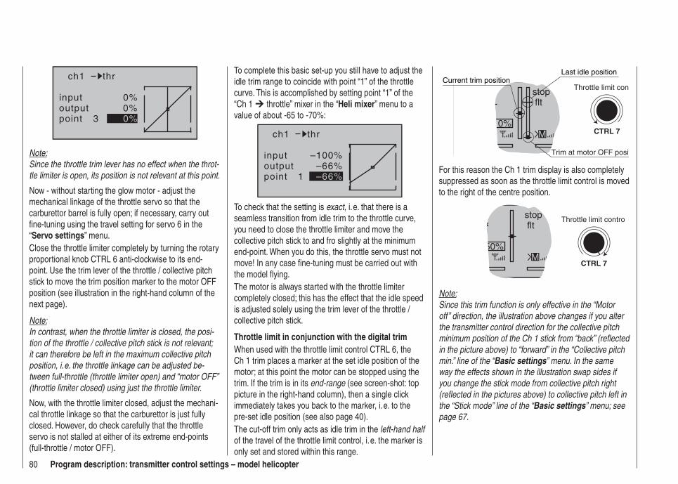
80 Program description: transmitter control settings – model helicopter
inputoutputpoint 3
0%0%0%
ch1 thr
Note:Since the throttle trim lever has no effect when the throt-tle limiter is open, its position is not relevant at this point.
Now - without starting the glow motor - adjust the mechanical linkage of the throttle servo so that the carburettor barrel is fully open; if necessary, carry out fi ne-tuning using the travel setting for servo 6 in the “Servo settings” menu.Close the throttle limiter completely by turning the rotary proportional knob CTRL 6 anti-clockwise to its end-point. Use the trim lever of the throttle / collective pitch stick to move the trim position marker to the motor OFF position (see illustration in the right-hand column of the next page).
Note:In contrast, when the throttle limiter is closed, the posi-tion of the throttle / collective pitch stick is not relevant; it can therefore be left in the maximum collective pitch position, i. e. the throttle linkage can be adjusted be-tween full-throttle (throttle limiter open) and “motor OFF” (throttle limiter closed) using just the throttle limiter.
Now, with the throttle limiter closed, adjust the mechani-cal throttle linkage so that the carburettor is just fully closed. However, do check carefully that the throttle servo is not stalled at either of its extreme end-points (full-throttle / motor OFF).
stop flt
0%M CTRL 7
Current trim position
Trim at motor OFF posit
Last idle position
Throttle limit cont
For this reason the Ch 1 trim display is also completely suppressed as soon as the throttle limit control is moved to the right of the centre position.
stop flt
50%M
CTRL 7
Throttle limit contro
Note:Since this trim function is only effective in the “Motor off” direction, the illustration above changes if you alter the transmitter control direction for the collective pitch minimum position of the Ch 1 stick from “back” (refl ected in the picture above) to “forward” in the “Collective pitch min.” line of the “Basic settings” menu. In the same way the effects shown in the illustration swap sides if you change the stick mode from collective pitch right (refl ected in the pictures above) to collective pitch left in the “Stick mode” line of the “Basic settings” menu; see page 67.
To complete this basic set-up you still have to adjust the idle trim range to coincide with point “1” of the throttle curve. This is accomplished by setting point “1” of the “Ch 1 throttle” mixer in the “Heli mixer” menu to a value of about -65 to -70%:
inputoutputpoint 1
–100%–66%–66%
ch1 thr
To check that the setting is exact, i. e. that there is a seamless transition from idle trim to the throttle curve, you need to close the throttle limiter and move the collective pitch stick to and fro slightly at the minimum end-point. When you do this, the throttle servo must not move! In any case fi ne-tuning must be carried out with the model fl ying.The motor is always started with the throttle limiter completely closed; this has the effect that the idle speed is adjusted solely using the trim lever of the throttle / collective pitch stick.
Throttle limit in conjunction with the digital trimWhen used with the throttle limit control CTRL 6, the Ch 1 trim places a marker at the set idle position of the motor; at this point the motor can be stopped using the trim. If the trim is in its end-range (see screen-shot: top picture in the right-hand column), then a single click immediately takes you back to the marker, i. e. to the pre-set idle position (see also page 40).The cut-off trim only acts as idle trim in the left-hand half of the travel of the throttle limit control, i. e. the marker is only set and stored within this range.

81For your notes

82 Dual Rate / Expo - fi xed-wing model
D/R ExpoSwitchable control characteristics for aileron, elevator and rudder
Use the arrow buttons of the left or right-hand touch-key to leaf through to the “D/R Expo” menu point of the multi-function menu:
mod. mem.servo set.D/R expowing mixer
base sett.contr set.phase tr imfree mixer
servo disp basic settfail-safe telemetry
A brief press on the central SET button of the right-hand touch-key opens this menu point:
100%
100%100%
0%
0%0%
aileelevrudd
DUAL EXPO
–––––––––
The Dual Rate / Expo function provides a means of switching to reduced control travels, and of infl uencing the travel characteristics, for aileron, elevator and rudder (control functions 2 ... 4).Dual Rate works in a similar way to transmitter control travel adjustment in the “Transmitter control settings” menu, i. e. it affects the corresponding stick function, re-gardless of whether that function controls a single servo or multiple servos via any number of complex mixer and coupling functions.For each switch position the servo travels can be set to any value within the range 0 to 125% of full travel.Expo works in a different way. If you set a value greater than 0%, exponential provides fi ne control of the model around the centre position of the primary control func-
tions (aileron, elevator and rudder), without forfeiting full travel at the end-points of stick movement. If you set a value lower than 0%, travel is increased around the neutral position, and diminishes towards the extremes of travel. The degree of “progression” can therefore be set to any value within the range -100% to +100%, where 0% equates to normal, linear control characteristics.Another application for exponential is to improve the linearity of rotary-output servos, which are the standard nowadays. With a rotary servo the movement of the control surface is inevitably non-linear, as the linear movement of the output disc or lever diminishes pro-gressively as the angular movement increases, i. e. the rate of travel of the control surface declines steadily towards the extremes, dependent upon the position of the linkage point on the output disc or lever. You can compensate for this effect by setting an Expo value greater than 0%, with the result that the angular travel of the output device increases disproportionately as stick travel increases.Like Dual Rates, the Expo setting applies directly to the corresponding stick function, regardless of whether that function controls a single servo or multiple servos via any number of complex mixer and coupling functions.The Dual Rate and Expo functions can be switched on and off together if you assign a switch to the function. The result of this is that Dual Rates and Expo can be controlled simultaneously using a single switch, and this can be advantageous - especially with high-speed models.
Flight phase dependent Dual-Rate and Expo set-tingsIf you have assigned a switch and - if you wish - a more appropriate name to one of the phases 2 to 4 in the
“Base settings” menu (see page 60), then this appears at bottom left, e. g. “normal”. If necessary, operate the associated switch in order to switch between the fl ight phases.
The basic set-up procedureSwitch to the desired fl ight phase, and then select 1. the desired line “aile”, “elev” or “rudd” using the arrow buttons of the left or right-hand touch-key.If necessary, use the 2. buttons of the left or right-hand touch key to select the desired column.Briefl y press the central 3. SET button of the right-hand touch-key: the corresponding input fi eld is now high-lighted (black background).Set the desired value using the arrow buttons of the 4. right-hand touch-key.Touch the central 5. SET button of the right-hand touch-key to conclude the input process.Simultaneously press the 6. or buttons of the right-hand touch-key (CLEAR) to reset any changed settings to the default values.
Dual Rate functionIf you wish to switch between two possible D/R settings, use the button of the left or right-hand touch-key to move to the right-hand column, marked at the bottom edge of the screen with the switch symbol , then briefl y touch the central SET button …
100% 0%aile
DUAL EXPO
–––
normal
push desired switchinto posit ion ON

83Dual Rate / Expo - fi xed-wing model
which indicates the direction of operation when you move the switch.For example, the system enables you to fl y with a linear curve characteristic in the one switch position, and to pre-set a value other than 0% in the other switch posi-tion.Select the right-hand column, marked with EXPO at the bottom edge of the screen, in order to change the Dual-Rate value for each of the two switch positions in the highlighted fi eld, using the arrow buttons of the right-hand touch-key.
100%
100%100%
+11%
0%
aileelevrudd
DUAL EXPO
22–––
+22%
normal
Simultaneously touching the or buttons of the right-hand touch-key (CLEAR) resets an altered value in the highlighted input fi eld to 0%.
Examples of different Expo values:
Ser
vo tr
avel
Ser
vo tr
avel
Ser
vo tr
avel
Stick deflection Stick deflection Stick deflection
Expo = +100% Expo = +50% Expo = –100%
In these examples the Dual Rate value is 100% in each case.
… and assign a physical switch as described in the sec-tion “Assigning switches and control switches” on page 39. The assigned switch appears on the screen together with a switch symbol which indicates the direction of operation of the switch. Select the left-hand column, marked DUAL at the bottom edge of the screen, and set the values for each of the two switch positions sepa-rately in the highlighted fi eld using the arrow buttons of the right-hand touch-key.Simultaneously touching the or buttons of the right-hand touch-key (CLEAR) resets an altered value in the highlighted fi eld to 100%.
Caution:For safety reasons the Dual Rate value should always be at least 20% of total control travel.
Examples of different Dual Rate values:
Ser
vo tr
avel
Ser
vo tr
avel
Ser
vo tr
avel
Stick deflection Stick deflection Stick deflection
Dual Rate = 100% Dual Rate = 50% Dual Rate = 20%
Exponential functionIf you wish to switch between two settings, use the button of the left or right-hand touch-key to move to the right-hand column, marked at the bottom edge of the screen with the switch symbol , then briefl y touch the central SET button and assign a switch to the func-tion, as described in the section “Assigning switches and control switches” on page 39. The assigned switch appears on the screen together with a switch symbol
Combined Dual Rate and ExpoIf you enter values for both Dual Rates and Expo, the two functions are superimposed as follows:
Ser
vo tr
avel
Ser
vo tr
avel
Ser
vo tr
avel
Stick deflection Stick deflection Stick deflection
Expo = +100%, DR = 125% Expo = +100%, DR = 50% Expo = –100%, DR = 50%
e. g. “switch back”:
88%
100%77%
0%
0%
DUAL EXPO
22–––
0%aileelevrudd
normal
and after moving switch “2” to the “forward” position:
122%
100%111%
+11%
0%
DUAL EXPO
22–––
+22%aileelevrudd
normal

84 Program description: Dual Rate / Expo – model helicopter
D/R ExpoSwitchable control characteristics for roll, pitch-axis and tail rotor
100%
100%100%
0%
0%0%
DUAL EXPO
–––––––––
rollnicktail
The Dual Rate / Expo function provides a means of switching to reduced control travels, and infl uencing the travel characteristics, for the roll, pitch-axis and tail rotor servos (control functions 2 … 4).A separate curve for control function 1 (motor / collective pitch) can be set individually for throttle, collective pitch and tail rotor in the “Helicopter mixers” menu. These curves feature up to fi ve separately programmable points; see the sections starting on page 94 and 169.Dual Rate works in a similar way to transmitter control travel adjustment in the “Transmitter control settings” menu, i. e. it affects the corresponding stick function, re-gardless of whether that function controls a single servo or multiple servos via any number of complex mixer and coupling functions.For each switch position the servo travels can be set to any value within the range 0 to 125% of full travel.Expo works in a different way. If you set a value greater than 0%, exponential provides fi ne control of the model around the centre position of the primary control func-tions (roll, pitch-axis and tail rotor), without forfeiting full travel at the end-points of stick movement. If you set a value lower than 0%, travel is increased around the neutral position, and diminishes towards the extremes of travel. The degree of “progression” can be set within the range -100% to +100%, where 0% equates to normal, linear control characteristics.
Another application for exponential is to improve the linearity of rotary-output servos, which are the standard nowadays. With a rotary servo the movement of the control surface is inevitably non-linear, as the linear movement of the output disc or lever diminishes pro-gressively as the angular movement increases, i. e. the rate of travel of the control surface declines steadily towards the extremes, dependent upon the position of the linkage point on the output disc or lever. You can compensate for this effect by setting an Expo value greater than 0%, with the result that the angular travel of the output device increases disproportionately as stick travel increases.Like Dual Rates, the Expo setting applies directly to the corresponding stick function, regardless of whether that function controls a single servo or multiple servos via any number of complex mixer and coupling functions.The Dual Rate and Expo functions can also be switched on and off together if you assign a switch to the func-tion. The result of this is that Dual Rates and Expo can be controlled simultaneously using a single switch, and this can be advantageous - especially with high-speed models.
Flight phase dependent Dual-Rate and Expo set-tingsIf you have assigned a switch and - if you wish - a more appropriate name to one of the phases 2, 3 or Auto-rotation in the “Basic settings” menu (see page 68 and 69), then this appears at bottom left, e. g. “normal”. If necessary, operate the associated switch in order to switch between the fl ight phases.
The basic set-up procedureSwitch to the desired fl ight phase, and then select 1.
the desired line “Roll”, “Pitch” or “Tail” using the arrow buttons of the left or right-hand touch-key.If necessary, use the 2. buttons of the left or right-hand touch key to select the desired column.Briefl y press the central 3. SET button of the right-hand touch-key: the corresponding input fi eld is now high-lighted (black background).Set the desired value using the arrow buttons of the 4. right-hand touch-key.Touch the central 5. SET button of the right-hand touch-key to conclude the input process.Simultaneously press the 6. or buttons of the right-hand touch key (CLEAR) to reset any changed settings to the default values.
Dual Rate functionIf you wish to switch between two possible D/R settings, use the button of the left or right-hand touch-key to move to the right-hand column, marked at the bottom edge of the screen with the switch symbol , briefl y touch the central SET button …
100% 0%roll
DUAL EXPO
–––push desired switchinto posit ion ON
… and assign a physical switch as described in the sec-tion “Assigning switches and control switches” on page 39. The assigned switch appears on the screen together with a switch symbol which indicates the direction of operation of the switch.Select the left-hand column, marked DUAL at the bottom
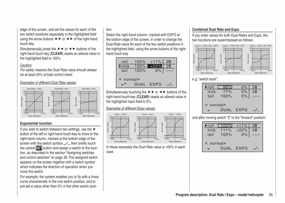
85Program description: Dual Rate / Expo – model helicopter
Combined Dual Rate and ExpoIf you enter values for both Dual Rates and Expo, the two functions are superimposed as follows:
Ser
vo tr
avel
Ser
vo tr
avel
Ser
vo tr
avel
Stick deflection Stick deflection Stick deflection
Expo = +100%, DR = 125% Expo = +100%, DR = 50% Expo = –100%, DR = 50%
e. g. “switch back”:
100% 0%
DUAL EXPO
–––
88%77%
0% 220%
rollnicktail
normal
and after moving switch “2” to the “forward” position:
100% 0%
DUAL EXPO
–––
122%111%
+11% 22+22%
rollnicktail
normal
edge of the screen, and set the values for each of the two switch positions separately in the highlighted fi eld using the arrow buttons or of the right-hand touch-key.Simultaneously press the or buttons of the right-hand touch key (CLEAR) resets an altered value in the highlighted fi eld to 100%.
Caution:For safety reasons the Dual Rate value should always be at least 20% of total control travel.
Examples of different Dual Rate values:
Ser
vo tr
avel
Ser
vo tr
avel
Ser
vo tr
avel
Stick deflection Stick deflection Stick deflection
Dual Rate = 100% Dual Rate = 50% Dual Rate = 20%
Exponential functionIf you wish to switch between two settings, use the button of the left or right-hand touch-key to move to the right-hand column, marked at the bottom edge of the screen with the switch symbol , then briefl y touch the central SET button and assign a switch to the func-tion, as described in the section “Assigning switches and control switches” on page 39. The assigned switch appears on the screen together with a switch symbol which indicates the direction of operation when you move the switch.For example, the system enables you to fl y with a linear curve characteristic in the one switch position, and to pre-set a value other than 0% in the other switch posi-
tion.Select the right-hand column, marked with EXPO at the bottom edge of the screen, in order to change the Dual-Rate value for each of the two switch positions in the highlighted fi eld, using the arrow buttons of the right-hand touch-key.
100%
100%100%
0%
rollnicktail
DUAL EXPO
–––
+11% 22+22%
normal
Simultaneously touching the or buttons of the right-hand touch-key (CLEAR) resets an altered value in the highlighted input fi eld to 0%.
Examples of different Expo values:S
ervo
trav
el
Ser
vo tr
avel
Ser
vo tr
avel
Stick deflection Stick deflection Stick deflection
Expo = +100% Expo = +50% Expo = –100%
In these examples the Dual Rate value is 100% in each case.
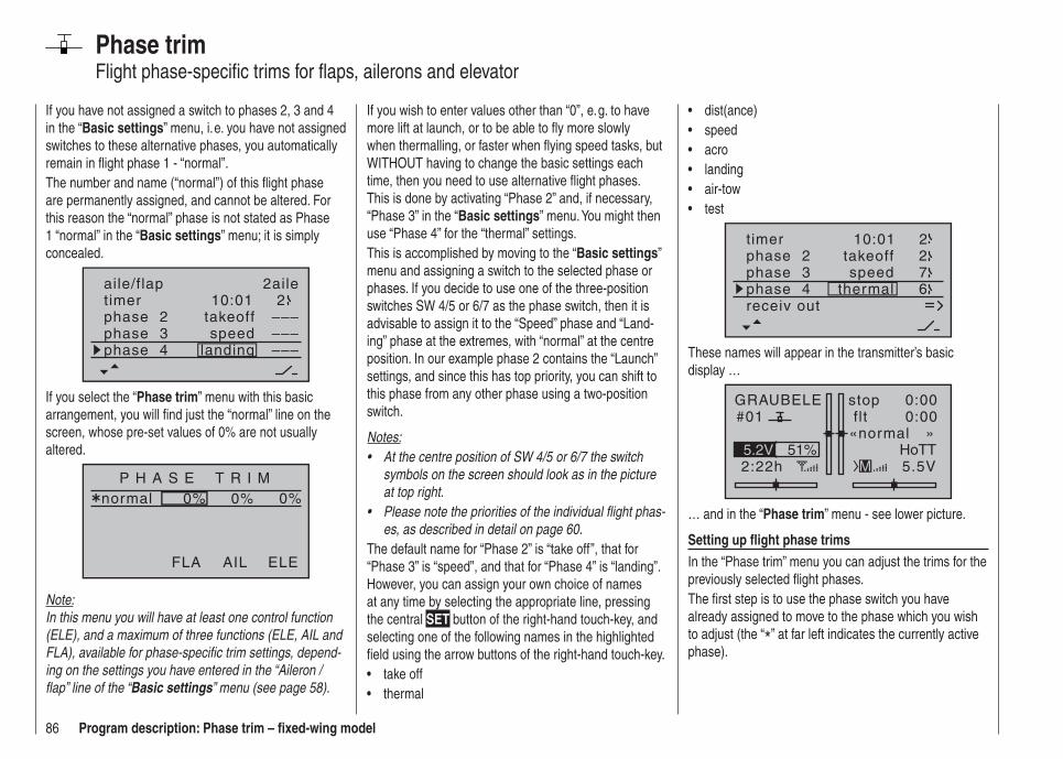
86 Program description: Phase trim – fi xed-wing model
Phase trimFlight phase-specifi c trims for fl aps, ailerons and elevator
If you wish to enter values other than “0”, e. g. to have more lift at launch, or to be able to fl y more slowly when thermalling, or faster when fl ying speed tasks, but WITHOUT having to change the basic settings each time, then you need to use alternative fl ight phases. This is done by activating “Phase 2” and, if necessary, “Phase 3” in the “Basic settings” menu. You might then use “Phase 4” for the “thermal” settings.This is accomplished by moving to the “Basic settings” menu and assigning a switch to the selected phase or phases. If you decide to use one of the three-position switches SW 4/5 or 6/7 as the phase switch, then it is advisable to assign it to the “Speed” phase and “Land-ing” phase at the extremes, with “normal” at the centre position. In our example phase 2 contains the “Launch” settings, and since this has top priority, you can shift to this phase from any other phase using a two-position switch.
Notes:At the centre position of SW 4/5 or 6/7 the switch • symbols on the screen should look as in the picture at top right.Please note the priorities of the individual fl ight phas-• es, as described in detail on page 60.
The default name for “Phase 2” is “take off”, that for “Phase 3” is “speed”, and that for “Phase 4” is “landing”. However, you can assign your own choice of names at any time by selecting the appropriate line, pressing the central SET button of the right-hand touch-key, and selecting one of the following names in the highlighted fi eld using the arrow buttons of the right-hand touch-key.
take off• thermal•
If you have not assigned a switch to phases 2, 3 and 4 in the “Basic settings” menu, i. e. you have not assigned switches to these alternative phases, you automatically remain in fl ight phase 1 - “normal”.The number and name (“normal”) of this fl ight phase are permanently assigned, and cannot be altered. For this reason the “normal” phase is not stated as Phase 1 “normal” in the “Basic settings” menu; it is simply concealed.
10:01 2phase 2phase 3phase 4
takeoff
landingspeed
–––––––––
aile/flap 2ailetimer
If you select the “Phase trim” menu with this basic arrangement, you will fi nd just the “normal” line on the screen, whose pre-set values of 0% are not usually altered.
P H A S E T R I Mnormal 0%0%0%
AIL ELEFLA
Note:In this menu you will have at least one control function (ELE), and a maximum of three functions (ELE, AIL and FLA), available for phase-specifi c trim settings, depend-ing on the settings you have entered in the “Aileron / fl ap” line of the “Basic settings” menu (see page 58).
dist(ance)• speed• acro• landing• air-tow• test•
timer 10:01 2phase 2phase 3phase 4 thermal
takeoffspeed
672
receiv out
These names will appear in the transmitter’s basic display …
GRAUBELE#01
2:22h
stop flt«normal »
0:000:00
5.5V51%5.2V HoTT
M
… and in the “Phase trim” menu - see lower picture.
Setting up fl ight phase trimsIn the “Phase trim” menu you can adjust the trims for the previously selected fl ight phases.The fi rst step is to use the phase switch you have already assigned to move to the phase which you wish to adjust (the “*” at far left indicates the currently active phase).
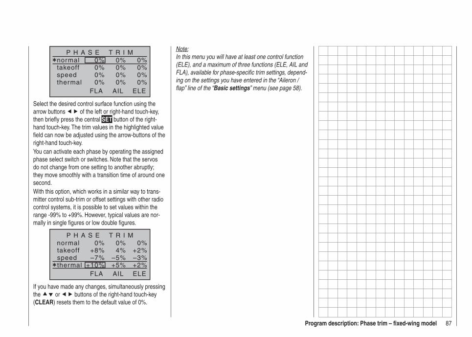
87Program description: Phase trim – fi xed-wing model
P H A S E T R I Mnormal 0%0%0%takeoffspeedthermal
0%0%0%0%0%0%0%0%0%
AIL ELEFLA
Select the desired control surface function using the arrow buttons of the left or right-hand touch-key, then briefl y press the central SET button of the right-hand touch-key. The trim values in the highlighted value fi eld can now be adjusted using the arrow-buttons of the right-hand touch-key.You can activate each phase by operating the assigned phase select switch or switches. Note that the servos do not change from one setting to another abruptly; they move smoothly with a transition time of around one second.With this option, which works in a similar way to trans-mitter control sub-trim or offset settings with other radio control systems, it is possible to set values within the range -99% to +99%. However, typical values are nor-mally in single fi gures or low double fi gures.
normal 0%0%0%+2%4%+8%–3%–5%–7%+2%+5%+10%
P H A S E T R I M
takeoffspeedthermal
AIL ELEFLA
If you have made any changes, simultaneously pressing the or buttons of the right-hand touch-key (CLEAR) resets them to the default value of 0%.
Note:In this menu you will have at least one control function (ELE), and a maximum of three functions (ELE, AIL and FLA), available for phase-specifi c trim settings, depend-ing on the settings you have entered in the “Aileron / fl ap” line of the “Basic settings” menu (see page 58).

88 Program description: wing mixers – fi xed-wing model
Fixed-wing mixers
0%
0%0%
0%0%0%0%0%0%0%0%0%
–––––––––––––––––––––––––––––––––
ai la i l
d i f f a i l e .
ruddflaps
brakbrakbrak
elevflapaile
elevelevflap
flapaileelev
flapd i f f – r e d
aile
d i f f f l a p s
(The display varies according to the information you have entered in the “Motor at Ch 1” and “Ail / Flap” lines in the “Basic settings” menu. The selection above shows the maximum number of options, and equates to the setting “No (motor)” and “2AIL 2FL”).
The mx-16 HoTT transmitter’s program contains a se-ries of pre-programmed coupling functions, and all you have to do is set the mixer ratios and (optionally) assign a switch. The number of pre-programmed mixer func-tions in the mixer list will vary according to the pre-set “model type” (tail type, number of wing servos, with or without motor - see the section starting on page 56). For example, if your model is not fi tted with camber-chang-ing fl aps, and you have not entered any fl ap servos in the “Basic settings” menu, the software automatically suppresses all the fl ap mixers, as are the “Brake NN *“ mixers if you enter “Idle forward” or “Idle back” in the “Motor at Ch 1” line. This makes the menus clearer and easier to understand, and also avoids potential program-ming errors.
What is a mixer?The basic function
In many models it is often desirable to use a mixer to couple various control systems, e. g. to link the ailerons and rudder, or to inter-connect a pair of servos where two control surfaces are actuated by separate servos. In all these cases the signal which fl ows directly from the “output” of a transmitter stick to the associated servo is “bled off” at a particular point - this effect can also be “concealed” in transmitter control options such as “D/R Expo” or “Transmitter control settings” - and the derived signal is then processed in such a way that it affects the “input” of another control channel, and therefore eventually another receiver output.
Example: V-tail mixer
3 3
4
e4
8 V
C 5
77B
sN
410
Se
v4
8 V
C 5
77es
N 4
10
4
V-tail mixer
Con
trol
func
tion
inpu
ts
Con
trol
cha
nnel
s(r
ecei
ver
outp
uts)
Elevator stick
Rudder stick
Right rudder / elevator
Left rudder / elevator
Rudder
Elevator
Elevator
Rud
der
Rud
der
Ele
vato
r
The mx-16 HoTT transmitter software contains a large number of pre-programmed coupling functions as standard, designed to mix together two (or more) control channels. The mixer required in this example is sup-plied “ready-made” in the software, and just has to be activated in the “tail” line of the “Basic settings” menu in the form of “V-tail”.The software also includes three freely programmable linear mixers in the fi xed-wing and helicopter programs, all of which can be used in each model memory.
* NN = Nomen Nominandum (name to be stated)
For more information please refer to the general notes on “Free mixers” in the section of this manual starting on page 106.

89Program description: wing mixers – fi xed-wing model
ing fl aps are defi ned; this is intentional, as it elimi-nates the danger of errors when a fl ap command is given.
The basic programming procedureUse the 1. buttons of the left or right-hand touch-key to select the desired mixer.Use the2. button of the left or right-hand touch-key to move to the right-hand column, marked by the switch symbol at the bottom edge of the screen.Touch the central 3. SET button of the right-hand touch-key; the corresponding input fi eld is now highlighted (black background).Use the arrow buttons of the right-hand touch-key to 4. set the desired value, and assign the switch if neces-sary, as described on page 39.With the exception of the “Diff. red.” line, negative and positive parameter values are possible; this may be necessary to obtain the correct direction of servo ro-tation (control surface defl ection).Simultaneously pressing the or buttons of the right-hand touch-key (CLEAR) resets an altered value to the default value.Touch the central 5. SET button of the right-hand touch-key to conclude the input process.
Mixer neutral point (offset)
The neutral point of the mixers … Aileron NN * Elevator NN * Elevator NN *… is by default the zero point of the transmitter control, i. e. that is the point at which they have no effect. At the
end-point of the transmitter control the full mixer value is applied.The default neutral point (“offset”) of the mixers … Airbrake NN *… at which the airbrakes are always retracted, is the forward position of the Ch 1 stick (throttle / airbrakes) if you select “none” in the “Motor at Ch 1” line of the “Basic settings” menu, and is the back position of the Ch 1 stick if you select “none/inv”.
diff aile (differential aileron travel)
Aileron differential compensates for an unwanted side-effect which occurs when ailerons are defl ected: the problem known as “adverse yaw”. When ailerons are defl ected, the drag generated by the down-going aileron is greater than that produced by the up-going aileron. The differential drag causes a yawing motion around the vertical axis in the opposite direction to the desired turn. This effect is much more pronounced in model gliders with high aspect ratio wings than in power models with their much shorter moment arms, and usually has to be countered by giving a simultaneous rudder defl ection in the opposite direction to the yaw. However, this in turns causes additional drag and reduces the aircraft’s ef-fi ciency even further.Aileron differential reduces the angular travel of the down-going aileron relative to the up-going aileron, and this reduces the drag and therefore the adverse yaw. However, electronic differential can only be applied if each aileron is actuated by its own servo, usually mounted in the wings themselves. The shorter pushrods also result in virtually slop-free aileron linkages with reliable centring.Mechanical solutions are also possible, but they usually
Notes:There are various alternative methods of positioning • the camber-changing fl aps; these include:a) settling on just one position per fl ight phase, sim-
ply by setting appropriate trim values in the “Pha-se trim” menu, as described on the preceding double-page;
b) controlling the fl aps manually using any transmit-ter control assigned to “Input 6” (in the “Transmit-ter control settings” menu - see page 74), after setting the basic fl ap positions in the “Phase trim” menu, as described earlier. Ideally the transmit-ter control would be one of the rotary proportional controls CTRL 6 … 8.
The selected transmitter control directly operates the two fl ap servos connected to receiver outputs 6 and 7, assuming that you have specifi ed fl aps in the “Ail. / Flap” line of the “Basic settings” menu. The same control determines the fl ap setting of the ailerons via the percentage value entered in the “FL AIL” mixer line.
However, for fi ner control of the fl ap positions, we recommend that you reduce their travel to about 25% in the “E6” line of the “Transmitter control settings” menu.
c) It is also possible to leave the default setting of “0%” in the appropriate line of the “FL AIL” menu, and to assign the same transmitter con-trol to both input 6 and input 5 in the “Transmitter control settings” menu. The magnitude of the ef-fect on the two pairs of wing fl aps can then be ad-justed using the servo travel adjustment facility.
If a transmitter control is assigned to input “7”, it will • be de-coupled by the software if two camber-chang- * NN = Nomen Nominandum (name to be stated)
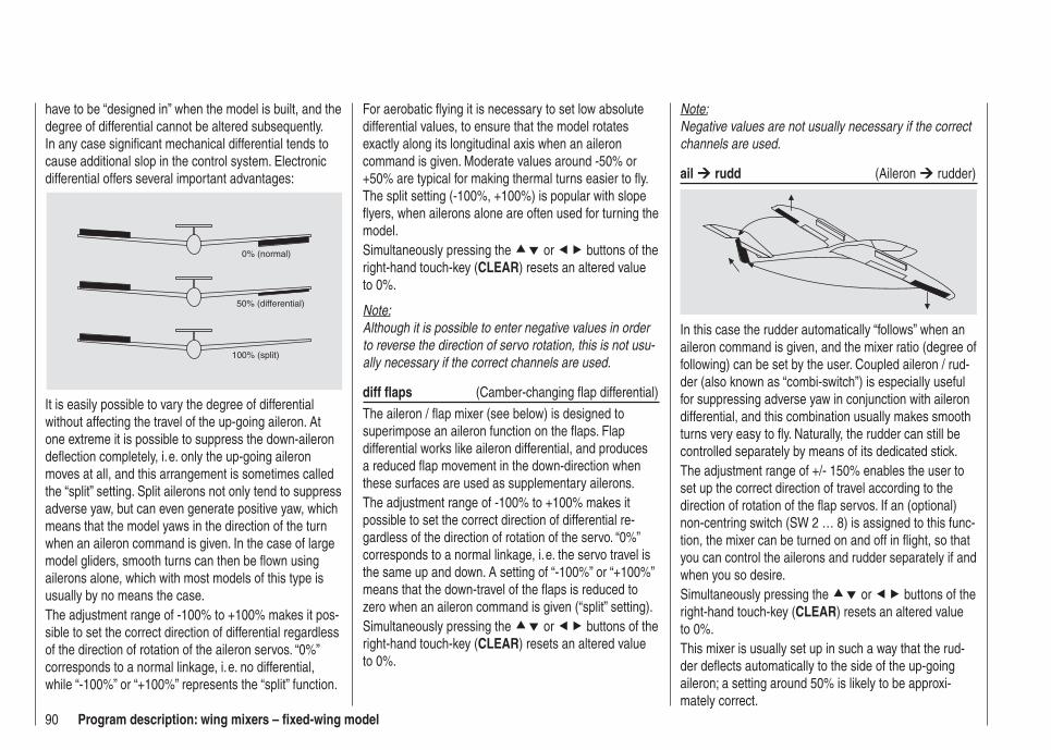
90 Program description: wing mixers – fi xed-wing model
Note:Negative values are not usually necessary if the correct channels are used.
ail rudd (Aileron rudder)
In this case the rudder automatically “follows” when an aileron command is given, and the mixer ratio (degree of following) can be set by the user. Coupled aileron / rud-der (also known as “combi-switch”) is especially useful for suppressing adverse yaw in conjunction with aileron differential, and this combination usually makes smooth turns very easy to fl y. Naturally, the rudder can still be controlled separately by means of its dedicated stick.The adjustment range of +/- 150% enables the user to set up the correct direction of travel according to the direction of rotation of the fl ap servos. If an (optional) non-centring switch (SW 2 … 8) is assigned to this func-tion, the mixer can be turned on and off in fl ight, so that you can control the ailerons and rudder separately if and when you so desire.Simultaneously pressing the or buttons of the right-hand touch-key (CLEAR) resets an altered value to 0%.This mixer is usually set up in such a way that the rud-der defl ects automatically to the side of the up-going aileron; a setting around 50% is likely to be approxi-mately correct.
For aerobatic fl ying it is necessary to set low absolute differential values, to ensure that the model rotates exactly along its longitudinal axis when an aileron command is given. Moderate values around -50% or +50% are typical for making thermal turns easier to fl y. The split setting (-100%, +100%) is popular with slope fl yers, when ailerons alone are often used for turning the model.Simultaneously pressing the or buttons of the right-hand touch-key (CLEAR) resets an altered value to 0%.
Note:Although it is possible to enter negative values in order to reverse the direction of servo rotation, this is not usu-ally necessary if the correct channels are used.
diff fl aps (Camber-changing fl ap differential)
The aileron / fl ap mixer (see below) is designed to superimpose an aileron function on the fl aps. Flap differential works like aileron differential, and produces a reduced fl ap movement in the down-direction when these surfaces are used as supplementary ailerons.The adjustment range of -100% to +100% makes it possible to set the correct direction of differential re-gardless of the direction of rotation of the servo. “0%” corresponds to a normal linkage, i. e. the servo travel is the same up and down. A setting of “-100%” or “+100%” means that the down-travel of the fl aps is reduced to zero when an aileron command is given (“split” setting).Simultaneously pressing the or buttons of the right-hand touch-key (CLEAR) resets an altered value to 0%.
have to be “designed in” when the model is built, and the degree of differential cannot be altered subsequently. In any case signifi cant mechanical differential tends to cause additional slop in the control system. Electronic differential offers several important advantages:
0% (normal)
50% (differential)
100% (split)
It is easily possible to vary the degree of differential without affecting the travel of the up-going aileron. At one extreme it is possible to suppress the down-aileron defl ection completely, i. e. only the up-going aileron moves at all, and this arrangement is sometimes called the “split” setting. Split ailerons not only tend to suppress adverse yaw, but can even generate positive yaw, which means that the model yaws in the direction of the turn when an aileron command is given. In the case of large model gliders, smooth turns can then be fl own using ailerons alone, which with most models of this type is usually by no means the case.The adjustment range of -100% to +100% makes it pos-sible to set the correct direction of differential regardless of the direction of rotation of the aileron servos. “0%” corresponds to a normal linkage, i. e. no differential, while “-100%” or “+100%” represents the “split” function.
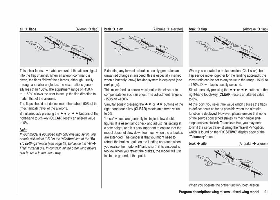
91Program description: wing mixers – fi xed-wing model
ail fl aps (Aileron fl ap)
This mixer feeds a variable amount of the aileron signal into the fl ap channel. When an aileron command is given, the fl aps “follow” the ailerons, although usually through a smaller angle, i. e. the mixer ratio is gener-ally less than 100%. The adjustment range of -150% to +150% allows the user to set up the fl ap direction to match that of the ailerons.The fl aps should not defl ect more than about 50% of the (mechanical) travel of the ailerons.Simultaneously pressing the or buttons of the right-hand touch-key (CLEAR) resets an altered value to 0%.
Note:If your model is equipped with only one fl ap servo, you should still select “2FL” in the “aile/fl ap” line of the “Ba-sic settings” menu (see page 58) but leave the “Ail Flap” mixer at 0%. In contrast, all the other wing mixers can be used in the usual way.
brak elev (Airbrake elevator)
or
Extending any form of airbrakes usually generates an unwanted change in airspeed; this is especially marked when a butterfl y (crow) braking system is deployed (see next page).This mixer feeds a corrective signal to the elevator to compensate for such an effect. The adjustment range is -150% to +150%.Simultaneously pressing the or buttons of the right-hand touch-key (CLEAR) resets an altered value to 0%.“Usual” values are generally in single to low double fi gures. It is essential to check and adjust this setting at a safe height, and it is also important to ensure that the model does not slow down too much when the airbrakes are extended. The danger is that you might need to retract the brakes again on the landing approach when you realise the model will “land short”; if its airspeed is too low when you retract the brakes, the model will just fall to the ground at that point.
brak fl ap (Airbrake fl ap)
When you operate the brake function (Ch 1 stick), both fl ap servos move together for the landing approach; the mixer ratio can be set to any value in the range -150% to +150%. Down-fl ap is usually selected.Simultaneously pressing the or buttons of the right-hand touch-key (CLEAR) resets an altered value to 0%.At this point you select the value which causes the fl aps to defl ect down as far as possible when the airbrake function is deployed. However, please ensure that none of the servos concerned strikes its mechanical end-stops (servos stalled). To achieve this, you may need to limit the servo travel(s) using the “Travel -/+” option, which is found on the “RX SERVO” display page of the “Telemetry” menu.
brak aile (Airbrake aileron)
When you operate the brake function, both aileron
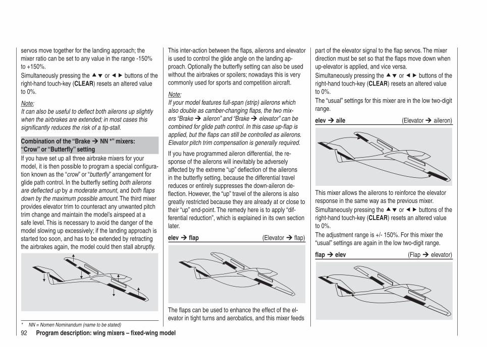
92 Program description: wing mixers – fi xed-wing model
part of the elevator signal to the fl ap servos. The mixer direction must be set so that the fl aps move down when up-elevator is applied, and vice versa.Simultaneously pressing the or buttons of the right-hand touch-key (CLEAR) resets an altered value to 0%.The “usual” settings for this mixer are in the low two-digit range.
elev aile (Elevator aileron)
This mixer allows the ailerons to reinforce the elevator response in the same way as the previous mixer.Simultaneously pressing the or buttons of the right-hand touch-key (CLEAR) resets an altered value to 0%.The adjustment range is +/- 150%. For this mixer the “usual” settings are again in the low two-digit range.
fl ap elev (Flap elevator)
This inter-action between the fl aps, ailerons and elevator is used to control the glide angle on the landing ap-proach. Optionally the butterfl y setting can also be used without the airbrakes or spoilers; nowadays this is very commonly used for sports and competition aircraft.
Note:If your model features full-span (strip) ailerons which also double as camber-changing fl aps, the two mix-ers “Brake aileron” and “Brake elevator” can be combined for glide path control. In this case up-fl ap is applied, but the fl aps can still be controlled as ailerons. Elevator pitch trim compensation is generally required.
If you have programmed aileron differential, the re-sponse of the ailerons will inevitably be adversely affected by the extreme “up” defl ection of the ailerons in the butterfl y setting, because the differential travel reduces or entirely suppresses the down-aileron de-fl ection. However, the “up” travel of the ailerons is also greatly restricted because they are already at or close to their “up” end-point. The remedy here is to apply “dif-ferential reduction”, which is explained in its own section later.
elev fl ap (Elevator fl ap)
The fl aps can be used to enhance the effect of the el-evator in tight turns and aerobatics, and this mixer feeds
servos move together for the landing approach; the mixer ratio can be set to any value in the range -150% to +150%.Simultaneously pressing the or buttons of the right-hand touch-key (CLEAR) resets an altered value to 0%.
Note:It can also be useful to defl ect both ailerons up slightly when the airbrakes are extended; in most cases this signifi cantly reduces the risk of a tip-stall.
Combination of the “Brake NN *” mixers:“Crow” or “Butterfl y” settingIf you have set up all three airbrake mixers for your model, it is then possible to program a special confi gura-tion known as the “crow” or “butterfl y” arrangement for glide path control. In the butterfl y setting both ailerons are defl ected up by a moderate amount, and both fl aps down by the maximum possible amount. The third mixer provides elevator trim to counteract any unwanted pitch trim change and maintain the model’s airspeed at a safe level. This is necessary to avoid the danger of the model slowing up excessively; if the landing approach is started too soon, and has to be extended by retracting the airbrakes again, the model could then stall abruptly.
* NN = Nomen Nominandum (name to be stated)
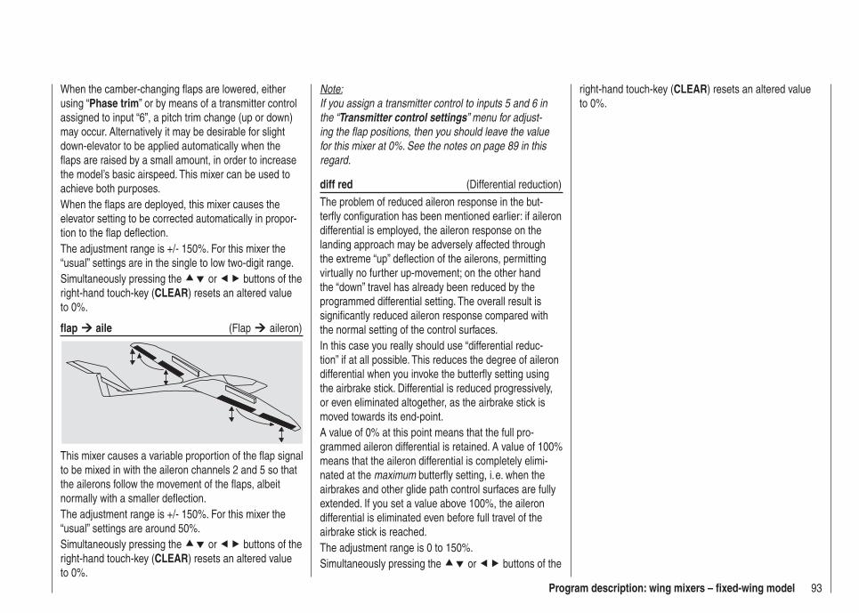
93Program description: wing mixers – fi xed-wing model
When the camber-changing fl aps are lowered, either using “Phase trim” or by means of a transmitter control assigned to input “6”, a pitch trim change (up or down) may occur. Alternatively it may be desirable for slight down-elevator to be applied automatically when the fl aps are raised by a small amount, in order to increase the model’s basic airspeed. This mixer can be used to achieve both purposes.When the fl aps are deployed, this mixer causes the elevator setting to be corrected automatically in propor-tion to the fl ap defl ection.The adjustment range is +/- 150%. For this mixer the “usual” settings are in the single to low two-digit range.Simultaneously pressing the or buttons of the right-hand touch-key (CLEAR) resets an altered value to 0%.
fl ap aile (Flap aileron)
This mixer causes a variable proportion of the fl ap signal to be mixed in with the aileron channels 2 and 5 so that the ailerons follow the movement of the fl aps, albeit normally with a smaller defl ection.The adjustment range is +/- 150%. For this mixer the “usual” settings are around 50%.Simultaneously pressing the or buttons of the right-hand touch-key (CLEAR) resets an altered value to 0%.
Note:If you assign a transmitter control to inputs 5 and 6 in the “Transmitter control settings” menu for adjust-ing the fl ap positions, then you should leave the value for this mixer at 0%. See the notes on page 89 in this regard.
diff red (Differential reduction)
The problem of reduced aileron response in the but-terfl y confi guration has been mentioned earlier: if aileron differential is employed, the aileron response on the landing approach may be adversely affected through the extreme “up” defl ection of the ailerons, permitting virtually no further up-movement; on the other hand the “down” travel has already been reduced by the programmed differential setting. The overall result is signifi cantly reduced aileron response compared with the normal setting of the control surfaces.In this case you really should use “differential reduc-tion” if at all possible. This reduces the degree of aileron differential when you invoke the butterfl y setting using the airbrake stick. Differential is reduced progressively, or even eliminated altogether, as the airbrake stick is moved towards its end-point.A value of 0% at this point means that the full pro-grammed aileron differential is retained. A value of 100% means that the aileron differential is completely elimi-nated at the maximum butterfl y setting, i. e. when the airbrakes and other glide path control surfaces are fully extended. If you set a value above 100%, the aileron differential is eliminated even before full travel of the airbrake stick is reached.The adjustment range is 0 to 150%.Simultaneously pressing the or buttons of the
right-hand touch-key (CLEAR) resets an altered value to 0%.
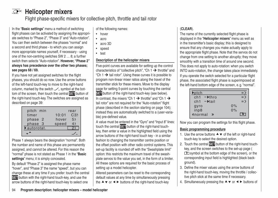
94 Program description: helicopter mixers – model helicopter
Helicopter mixersFlight phase-specifi c mixers for collective pitch, throttle and tail rotor
In the “Basic settings” menu a method of switching fl ight phases can be activated by assigning the appropri-ate switches to “Phase 2”, “Phase 3” and “Auto-rotation”. You can then switch between the phases “normal” and a second and third phase - to which you can assign more appropriate names yourself, if necessary - using one of the non-centring switches SW 2 … 8; a further switch then selects “Auto-rotation”. However, “Phase 2” always has precedence over the other two phases; see pages 68 / 69.If you have not yet assigned switches for the fl ight phases, you should do so now. Use the arrow buttons of the left-hand touch-key to move to the right-hand column, marked by the switch symbol at the bot-tom of the screen, then touch the central SET button of the right-hand touch-key. The switches are assigned as described on page 39:
pitch min reartimer 10:01 C3phase 2phase 3
hoverspeed
autorotat. 2
54
Phase 1 always bears the designation “normal”. Both the number and name of this phase are permanently assigned, and cannot be altered. For this reason the “normal” phase is not stated as Phase 1 in the “Basic settings” menu; it is simply concealed.By default “Phase 2” is assigned the phase name “hover”, and “Phase 3” the name “speed”, but you can change these at any time if you prefer: touch the central SET button with the right-hand touch-key, and use the arrow buttons of the right-hand touch-key to select one
of the following names:hover• acro• acro 3D• speed• test•
Description of the helicopter mixersFive-point curves are available for setting up the control characteristics of “collective pitch”, “Ch 1 throttle” and “Ch 1 tail rotor”. Using these curves it is possible to program non-linear mixer ratios along the travel of the transmitter stick for these mixers. Move to the display page for setting 5-point curves by touching the central SET button of the right-hand touch-key (see below).In contrast, the mixers “Ch 1 throttle” and “Ch 1 tail rotor” are not required for the “Auto-rotation” fl ight phase (described in the section starting on page 104); instead they are automatically switched to a (user-varia-ble) pre-defi ned value.A value must be entered in the “Gyro” and “Input 8” lines: touch the central SET button of the right-hand touch-key, then enter a value in the highlighted fi eld using the arrow buttons of the right-hand touch key - in a similar fashion to changing the transmitter centre position or the offset position with other radio control systems. This set-up facility is rounded off with the “Swashplate limit” option: this restricts the maximum travel of the swash-plate servos to the value you set, in the form of a limiter. All these options are required for the basic process of setting up a model helicopter.Altered parameters can be reset to the corresponding default values at any time by simultaneously pressing the or buttons of the right-hand touch-key
(CLEAR).The name of the currently selected fl ight phase is displayed in the “Helicopter mixers” menu as well as in the transmitter’s basic display; this is designed to ensure that any changes you make actually apply to the appropriate fl ight phase. Note that the servos do not change from one setting to another abruptly; they move smoothly with a transition time of around one second. This does not apply to auto-rotation: when you switch INTO auto-rotation, the change takes place immediately.If you operate the switch selected for a particular fl ight phase, the associated fl ight phase is superimposed at the left-hand bottom edge of the screen, e. g. “normal”.
ch1ch1
ptchthrotail
normal
gyro 0%inp8 0%
Now you can program the settings for this fl ight phase.
Basic programming procedureUse the arrow buttons 1. of the left or right-hand touch-key to select the desired option.Touch the central 2. SET button of the right-hand touch-key, and the screen switches to the set-up page (
symbol at the bottom edge of the screen), or the corresponding input fi eld is highlighted (black back-ground).Defi ne the mixer values using the arrow buttons of 3. the right-hand touch-key, moving the throttle / collec-tive pitch stick at the same time if necessary.Simultaneously pressing the 4. or buttons of
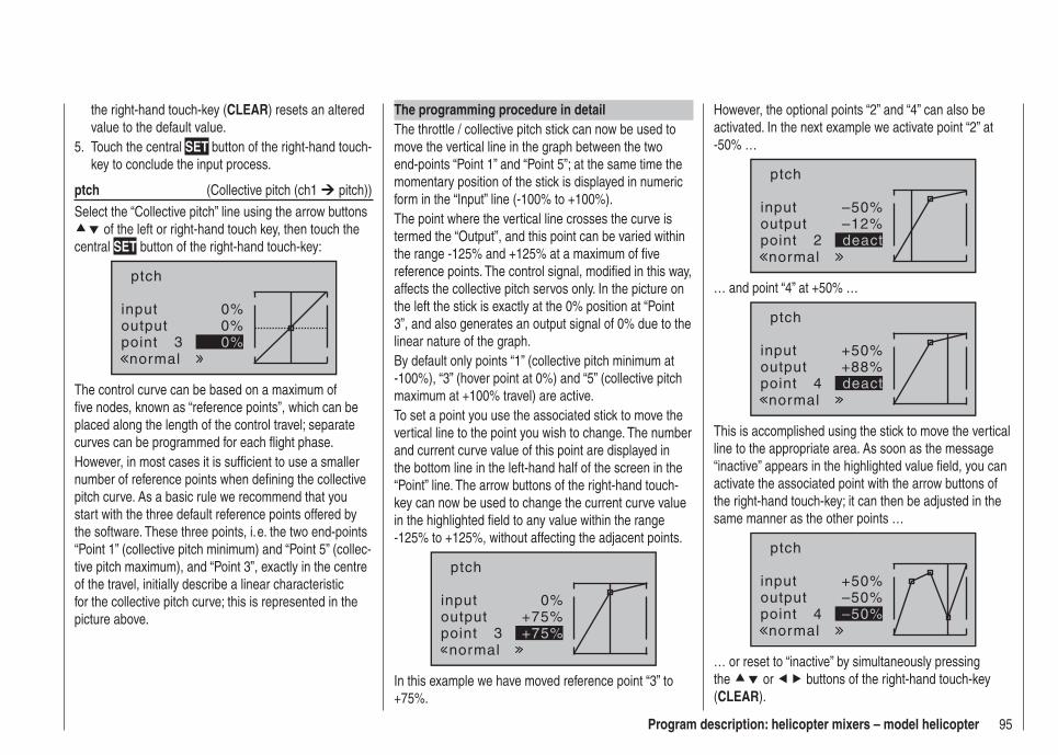
95Program description: helicopter mixers – model helicopter
the right-hand touch-key (CLEAR) resets an altered value to the default value.Touch the central 5. SET button of the right-hand touch-key to conclude the input process.
ptch (Collective pitch (ch1 pitch))
Select the “Collective pitch” line using the arrow buttons of the left or right-hand touch key, then touch the
central SET button of the right-hand touch-key:
inputoutputpoint 3
0%0%0%
ptch
normal
The control curve can be based on a maximum of fi ve nodes, known as “reference points”, which can be placed along the length of the control travel; separate curves can be programmed for each fl ight phase.However, in most cases it is suffi cient to use a smaller number of reference points when defi ning the collective pitch curve. As a basic rule we recommend that you start with the three default reference points offered by the software. These three points, i. e. the two end-points “Point 1” (collective pitch minimum) and “Point 5” (collec-tive pitch maximum), and “Point 3”, exactly in the centre of the travel, initially describe a linear characteristic for the collective pitch curve; this is represented in the picture above.
The programming procedure in detailThe throttle / collective pitch stick can now be used to move the vertical line in the graph between the two end-points “Point 1” and “Point 5”; at the same time the momentary position of the stick is displayed in numeric form in the “Input” line (-100% to +100%).The point where the vertical line crosses the curve is termed the “Output”, and this point can be varied within the range -125% and +125% at a maximum of fi ve reference points. The control signal, modifi ed in this way, affects the collective pitch servos only. In the picture on the left the stick is exactly at the 0% position at “Point 3”, and also generates an output signal of 0% due to the linear nature of the graph.By default only points “1” (collective pitch minimum at -100%), “3” (hover point at 0%) and “5” (collective pitch maximum at +100% travel) are active.To set a point you use the associated stick to move the vertical line to the point you wish to change. The number and current curve value of this point are displayed in the bottom line in the left-hand half of the screen in the “Point” line. The arrow buttons of the right-hand touch-key can now be used to change the current curve value in the highlighted fi eld to any value within the range -125% to +125%, without affecting the adjacent points.
inputoutputpoint 3
0%+75%+75%
ptch
normal
In this example we have moved reference point “3” to +75%.
However, the optional points “2” and “4” can also be activated. In the next example we activate point “2” at -50% …
inputoutputpoint 2
–50%–12%deact
ptch
normal
… and point “4” at +50% …
inputoutputpoint 4
+50%+88%deact
ptch
normal
This is accomplished using the stick to move the vertical line to the appropriate area. As soon as the message “inactive” appears in the highlighted value fi eld, you can activate the associated point with the arrow buttons of the right-hand touch-key; it can then be adjusted in the same manner as the other points …
inputoutputpoint 4
+50%–50%–50%
ptch
normal
… or reset to “inactive” by simultaneously pressing the or buttons of the right-hand touch-key (CLEAR).

96 Program description: helicopter mixers – model helicopter
Points “1” and “5”, however, CANNOT be disabled.
Note:The following illustration, and all the other pictures on this page, show a control curve which we prepared for illustration purposes only. Please note that the curve characteristics by no means represent real collective pitch curves!
inputoutputpoint 3
0%–50%–50%
ptch
normal
Typical collective pitch curves for different fl ight phases:+100% +100% +100%
100%100%100%
Ou
tpu
t
Ou
tpu
t
Ou
tpu
t
2 3 4 51 2 3 4 51 2 3 4 51
Control travel Control travel Control travel
Hover Aerobatics 3D
ch1 thro (throttle curve)
inputoutputpoint 3
0%0%0%
ch1
normal
thro
Helicopter with glow engine or electric motor and STANDARD SPEED CONTROLLERThis setting only affects the control curve of the throttle servo or speed controller.The method of setting up a throttle curve for a model helicopter fi tted with a speed governor or regulator is discussed later.The throttle curve can be defi ned using up to fi ve points, in a similar way to the collective pitch curve (see previous page).
In all cases the control curve must be set up in such • a way that the throttle is fully open, or the speed controller of an electric helicopter is at full power, at the end-point of the throttle / collective pitch stick, (exception: auto-rotation - see page 104).The hover point is normally located at the centre of • the stick travel, and the throttle setting should be adjusted relative to the collective pitch curve in such a way that the correct system rotational speed is obtained at this point.At the minimum position of the throttle / collective • pitch stick the throttle curve should initially be set up so that the (glow) motor runs at a distinctly higher speed compared to the idle setting, with the clutch reliably engaged.
In all fl ight phases the motor (glow or electric) is started and stopped using the throttle limiter (see below).If you are used to a different radio control system which uses two separate fl ight phases for this - “with idle-up” and “without idle-up”; therefore incurring the “loss” of one complete fl ight phase - please note that the throt-tle limiter renders this complication superfl uous, as the increased system rotational speed below the hover point in the mx-16 HoTT program is more fl exible, and can be fi ne-tuned more accurately, than the “idle-up” system used with earlier mc radio control systems.Ensure that the throttle limiter is closed before you start the glow motor, i. e. the throttle can only be adjusted within its idle range using the idle trim. Be sure to read the safety notes on page 102 which refer to this. If the idle is set too high when you switch the transmitter on, you will see and hear a clear warning!
stopSTARLET#02
2:22h
0:000:00
5.5V5.2V HoTT
mal »
M
throt t letoo
high !
The following three diagrams show typical 3-point throttle curves for different fl ight phases, such as hover, aerobat-ics and 3-D fl ying.
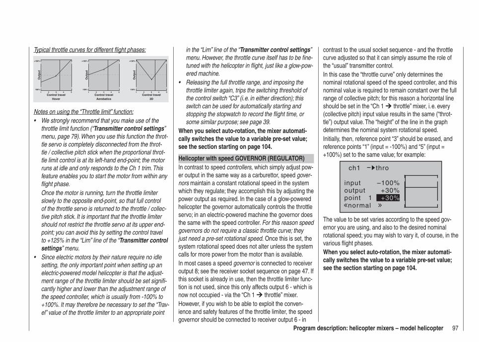
97Program description: helicopter mixers – model helicopter
Typical throttle curves for different fl ight phases:
+100% +100% +100%
100%100%100%
Ou
tpu
t
Ou
tpu
t
Ou
tpu
t
2 3 4 51 2 3 4 51 2 3 4 51
Control travel Control travel Control travelHover Aerobatics 3D
Notes on using the “Throttle limit” function:We strongly recommend that you make use of the • throttle limit function (“Transmitter control settings” menu, page 79). When you use this function the throt-tle servo is completely disconnected from the throt-tle / collective pitch stick when the proportional throt-tle limit control is at its left-hand end-point; the motor runs at idle and only responds to the Ch 1 trim. This feature enables you to start the motor from within any fl ight phase.Once the motor is running, turn the throttle limiter slowly to the opposite end-point, so that full control of the throttle servo is returned to the throttle / collec-tive pitch stick. It is important that the throttle limiter should not restrict the throttle servo at its upper end-point; you can avoid this by setting the control travel to +125% in the “Lim” line of the “Transmitter control settings” menu.Since electric motors by their nature require no idle • setting, the only important point when setting up an electric-powered model helicopter is that the adjust-ment range of the throttle limiter should be set signifi -cantly higher and lower than the adjustment range of the speed controller, which is usually from -100% to +100%. It may therefore be necessary to set the “Trav-el” value of the throttle limiter to an appropriate point
in the “Lim” line of the “Transmitter control settings” menu. However, the throttle curve itself has to be fi ne-tuned with the helicopter in fl ight, just like a glow-pow-ered machine.Releasing the full throttle range, and imposing the • throttle limiter again, trips the switching threshold of the control switch “C3” (i. e. in either direction); this switch can be used for automatically starting and stopping the stopwatch to record the fl ight time, or some similar purpose; see page 39.
When you select auto-rotation, the mixer automati-cally switches the value to a variable pre-set value; see the section starting on page 104.
Helicopter with speed GOVERNOR (REGULATOR)In contrast to speed controllers, which simply adjust pow-er output in the same way as a carburettor, speed gover-nors maintain a constant rotational speed in the system which they regulate; they accomplish this by adjusting the power output as required. In the case of a glow-powered helicopter the governor automatically controls the throttle servo; in an electric-powered machine the governor does the same with the speed controller. For this reason speed governors do not require a classic throttle curve; they just need a pre-set rotational speed. Once this is set, the system rotational speed does not alter unless the system calls for more power from the motor than is available.In most cases a speed governor is connected to receiver output 8; see the receiver socket sequence on page 47. If this socket is already in use, then the throttle limiter func-tion is not used, since this only affects output 6 - which is now not occupied - via the “Ch 1 throttle” mixer.However, if you wish to be able to exploit the conven-ience and safety features of the throttle limiter, the speed governor should be connected to receiver output 6 - in
contrast to the usual socket sequence - and the throttle curve adjusted so that it can simply assume the role of the “usual” transmitter control.In this case the “throttle curve” only determines the nominal rotational speed of the speed controller, and this nominal value is required to remain constant over the full range of collective pitch; for this reason a horizontal line should be set in the “Ch 1 throttle” mixer, i. e. every (collective pitch) input value results in the same (“throt-tle”) output value. The “height” of the line in the graph determines the nominal system rotational speed.Initially, then, reference point “3” should be erased, and reference points “1” (input = -100%) and “5” (input = +100%) set to the same value; for example:
inputoutputpoint 1
–100%+30%+30%
ch1
normal
thro
The value to be set varies according to the speed gov-ernor you are using, and also to the desired nominal rotational speed; you may wish to vary it, of course, in the various fl ight phases.When you select auto-rotation, the mixer automati-cally switches the value to a variable pre-set value; see the section starting on page 104.
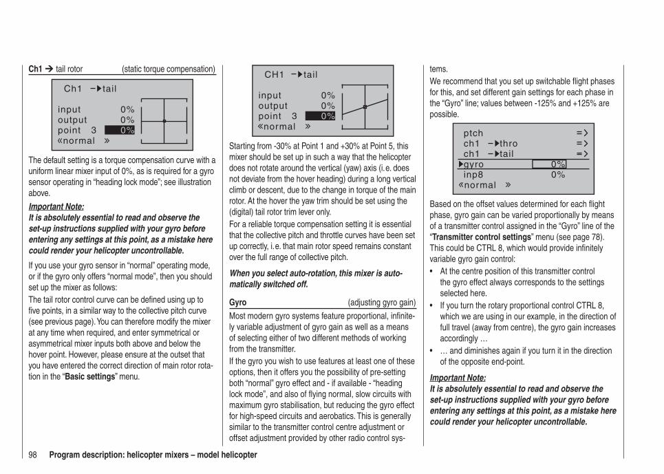
98 Program description: helicopter mixers – model helicopter
tems.We recommend that you set up switchable fl ight phases for this, and set different gain settings for each phase in the “Gyro” line; values between -125% and +125% are possible.
ch1ch1
ptchthrotail
normal
gyro 0%inp8 0%
Based on the offset values determined for each fl ight phase, gyro gain can be varied proportionally by means of a transmitter control assigned in the “Gyro” line of the “Transmitter control settings” menu (see page 78). This could be CTRL 8, which would provide infi nitely variable gyro gain control:
At the centre position of this transmitter control • the gyro effect always corresponds to the settings selected here.If you turn the rotary proportional control CTRL 8, • which we are using in our example, in the direction of full travel (away from centre), the gyro gain increases accordingly …… and diminishes again if you turn it in the direction • of the opposite end-point.
Important Note:It is absolutely essential to read and observe the set-up instructions supplied with your gyro before entering any settings at this point, as a mistake here could render your helicopter uncontrollable.
Ch1 tail rotor (static torque compensation)
inputoutputpoint 3
0%0%0%
Ch1
normal
tail
The default setting is a torque compensation curve with a uniform linear mixer input of 0%, as is required for a gyro sensor operating in “heading lock mode”; see illustration above.
Important Note:It is absolutely essential to read and observe the set-up instructions supplied with your gyro before entering any settings at this point, as a mistake here could render your helicopter uncontrollable.
If you use your gyro sensor in “normal” operating mode, or if the gyro only offers “normal mode”, then you should set up the mixer as follows:The tail rotor control curve can be defi ned using up to fi ve points, in a similar way to the collective pitch curve (see previous page). You can therefore modify the mixer at any time when required, and enter symmetrical or asymmetrical mixer inputs both above and below the hover point. However, please ensure at the outset that you have entered the correct direction of main rotor rota-tion in the “Basic settings” menu.
inputoutputpoint 3
0%0%0%
CH1
normal
tail
Starting from -30% at Point 1 and +30% at Point 5, this mixer should be set up in such a way that the helicopter does not rotate around the vertical (yaw) axis (i. e. does not deviate from the hover heading) during a long vertical climb or descent, due to the change in torque of the main rotor. At the hover the yaw trim should be set using the (digital) tail rotor trim lever only.For a reliable torque compensation setting it is essential that the collective pitch and throttle curves have been set up correctly, i. e. that main rotor speed remains constant over the full range of collective pitch.
When you select auto-rotation, this mixer is auto-matically switched off.
Gyro (adjusting gyro gain)
Most modern gyro systems feature proportional, infi nite-ly variable adjustment of gyro gain as well as a means of selecting either of two different methods of working from the transmitter.If the gyro you wish to use features at least one of these options, then it offers you the possibility of pre-setting both “normal” gyro effect and - if available - “heading lock mode”, and also of fl ying normal, slow circuits with maximum gyro stabilisation, but reducing the gyro effect for high-speed circuits and aerobatics. This is generally similar to the transmitter control centre adjustment or offset adjustment provided by other radio control sys-
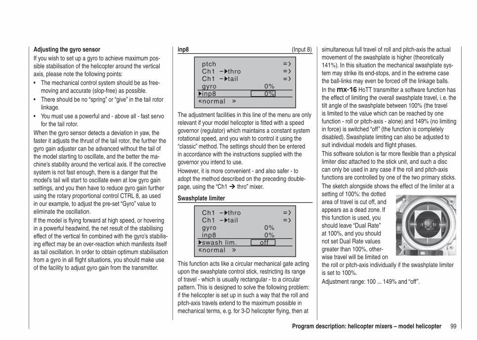
99Program description: helicopter mixers – model helicopter
Adjusting the gyro sensorIf you wish to set up a gyro to achieve maximum pos-sible stabilisation of the helicopter around the vertical axis, please note the following points:
The mechanical control system should be as free-• moving and accurate (slop-free) as possible.There should be no “spring” or “give” in the tail rotor • linkage.You must use a powerful and - above all - fast servo • for the tail rotor.
When the gyro sensor detects a deviation in yaw, the faster it adjusts the thrust of the tail rotor, the further the gyro gain adjuster can be advanced without the tail of the model starting to oscillate, and the better the ma-chine’s stability around the vertical axis. If the corrective system is not fast enough, there is a danger that the model’s tail will start to oscillate even at low gyro gain settings, and you then have to reduce gyro gain further using the rotary proportional control CTRL 8, as used in our example, to adjust the pre-set “Gyro” value to eliminate the oscillation.If the model is fl ying forward at high speed, or hovering in a powerful headwind, the net result of the stabilising effect of the vertical fi n combined with the gyro’s stabilis-ing effect may be an over-reaction which manifests itself as tail oscillation. In order to obtain optimum stabilisation from a gyro in all fl ight situations, you should make use of the facility to adjust gyro gain from the transmitter.
inp8 (Input 8)
Ch1Ch1
ptchthrotail
normal
gyro 0%inp8 0%
The adjustment facilities in this line of the menu are only relevant if your model helicopter is fi tted with a speed governor (regulator) which maintains a constant system rotational speed, and you wish to control it using the “classic” method. The settings should then be entered in accordance with the instructions supplied with the governor you intend to use.However, it is more convenient - and also safer - to adopt the method described on the preceding double-page, using the “Ch1 thro” mixer.
Swashplate limiter
Ch1Ch1
throtail
normal
gyro 0%inp8 0%swash lim. off
This function acts like a circular mechanical gate acting upon the swashplate control stick, restricting its range of travel - which is usually rectangular - to a circular pattern. This is designed to solve the following problem: if the helicopter is set up in such a way that the roll and pitch-axis travels extend to the maximum possible in mechanical terms, e. g. for 3-D helicopter fl ying, then at
simultaneous full travel of roll and pitch-axis the actual movement of the swashplate is higher (theoretically 141%). In this situation the mechanical swashplate sys-tem may strike its end-stops, and in the extreme case the ball-links may even be forced off the linkage balls.In the mx-16 HoTT transmitter a software function has the effect of limiting the overall swashplate travel, i. e. the tilt angle of the swashplate between 100% (the travel is limited to the value which can be reached by one function - roll or pitch-axis - alone) and 149% (no limiting in force) is switched “off” (the function is completely disabled). Swashplate limiting can also be adjusted to suit individual models and fl ight phases.This software solution is far more fl exible than a physical limiter disc attached to the stick unit, and such a disc can only be used in any case if the roll and pitch-axis functions are controlled by one of the two primary sticks.The sketch alongside shows the effect of the limiter at a setting of 100%: the dotted area of travel is cut off, and appears as a dead zone. If this function is used, you should leave “Dual Rate” at 100%, and you should not set Dual Rate values greater than 100%, other-wise travel will be limited on the roll or pitch-axis individually if the swashplate limiter is set to 100%.Adjustment range: 100 ... 149% and “off”.
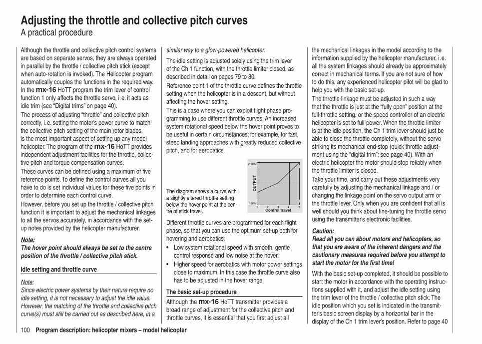
100 Program description: helicopter mixers – model helicopter
Adjusting the throttle and collective pitch curvesA practical procedure
Although the throttle and collective pitch control systems are based on separate servos, they are always operated in parallel by the throttle / collective pitch stick (except when auto-rotation is invoked). The Helicopter program automatically couples the functions in the required way. In the mx-16 HoTT program the trim lever of control function 1 only affects the throttle servo, i. e. it acts as idle trim (see “Digital trims” on page 40).The process of adjusting “throttle” and collective pitch correctly, i. e. setting the motor’s power curve to match the collective pitch setting of the main rotor blades, is the most important aspect of setting up any model helicopter. The program of the mx-16 HoTT provides independent adjustment facilities for the throttle, collec-tive pitch and torque compensation curves.These curves can be defi ned using a maximum of fi ve reference points. To defi ne the control curves all you have to do is set individual values for these fi ve points in order to determine each control curve.However, before you set up the throttle / collective pitch function it is important to adjust the mechanical linkages to all the servos accurately, in accordance with the set-up notes provided by the helicopter manufacturer.
Note:The hover point should always be set to the centre position of the throttle / collective pitch stick.
Idle setting and throttle curve
Note:Since electric power systems by their nature require no idle setting, it is not necessary to adjust the idle value. However, the matching of the throttle and collective pitch curve(s) must still be carried out as described here, in a
similar way to a glow-powered helicopter.
The idle setting is adjusted solely using the trim lever of the Ch 1 function, with the throttle limiter closed, as described in detail on pages 79 to 80.Reference point 1 of the throttle curve defi nes the throttle setting when the helicopter is in a descent, but without affecting the hover setting.This is a case where you can exploit fl ight phase pro-gramming to use different throttle curves. An increased system rotational speed below the hover point proves to be useful in certain circumstances; for example, for fast, steep landing approaches with greatly reduced collective pitch, and for aerobatics.
The diagram shows a curve with a slightly altered throttle setting below the hover point at the cen-tre of stick travel.
+100%
100%
OU
TP
UT
2 3 4 51Control travel
Different throttle curves are programmed for each fl ight phase, so that you can use the optimum set-up both for hovering and aerobatics:
Low system rotational speed with smooth, gentle • control response and low noise at the hover.Higher speed for aerobatics with motor power settings • close to maximum. In this case the throttle curve also has to be adjusted in the hover range.
The basic set-up procedureAlthough the mx-16 HoTT transmitter provides a broad range of adjustment for the collective pitch and throttle curves, it is essential that you fi rst adjust all
the mechanical linkages in the model according to the information supplied by the helicopter manufacturer, i. e. all the system linkages should already be approximately correct in mechanical terms. If you are not sure of how to do this, any experienced helicopter pilot will be glad to help you with the basic set-up.The throttle linkage must be adjusted in such a way that the throttle is just at the “fully open” position at the full-throttle setting, or the speed controller of an electric helicopter is set to full-power. When the throttle limiter is at the idle position, the Ch 1 trim lever should just be able to close the throttle completely, without the servo striking its mechanical end-stop (quick throttle adjust-ment using the “digital trim”: see page 40). With an electric helicopter the motor should stop reliably when the throttle limiter is closed.Take your time, and carry out these adjustments very carefully by adjusting the mechanical linkage and / or changing the linkage point on the servo output arm or the throttle lever. Only when you are confi dent that all is well should you think about fi ne-tuning the throttle servo using the transmitter’s electronic facilities.
Caution:Read all you can about motors and helicopters, so that you are aware of the inherent dangers and the cautionary measures required before you attempt to start the motor for the fi rst time!
With the basic set-up completed, it should be possible to start the motor in accordance with the operating instruc-tions supplied with it, and adjust the idle setting using the trim lever of the throttle / collective pitch stick. The idle position which you set is indicated in the transmit-ter’s basic screen display by a horizontal bar in the display of the Ch 1 trim lever’s position. Refer to page 40
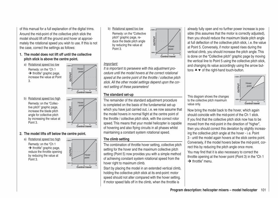
101Program description: helicopter mixers – model helicopter
already fully open and no further power increase is pos-sible (this assumes that the motor is correctly adjusted), then you should reduce the maximum blade pitch angle at full defl ection of the collective pitch stick, i. e. the value at Point 5. Conversely, if motor speed rises during the vertical climb, you should increase the pitch angle. This is done on the “Collective pitch” graphic page by moving the vertical line to Point 5 using the collective pitch stick, and changing its value accordingly using the arrow but-tons of the right-hand touch-button.
This diagram shows the changes to the collective pitch maximum value only.
+100%
100%
OU
TP
UT
2 3 4 51Control travel
Hoverpoint
Now bring the model back to the hover, which again should coincide with the mid-point of the Ch 1 stick. If you fi nd that the collective pitch stick now has to be moved from the mid-point in the direction of “higher”, then you should correct this deviation by slightly increas-ing the collective pitch angle at the hover - i. e. Point 3 - until the model again hovers at the stick centre point. Conversely, if the model hovers below the mid-point, cor-rect this by reducing the pitch angle once more.You may fi nd that it is also necessary to correct the throttle opening at the hover point (Point 3) in the “Ch 1
throttle” menu.
of this manual for a full explanation of the digital trims.Around the mid-point of the collective pitch stick the model should lift off the ground and hover at approxi-mately the rotational speed you wish to use. If this is not the case, correct the settings as follows:
1. The model does not lift off until the collective pitch stick is above the centre point.a) Rotational speed too low Remedy: on the “Ch 1
throttle” graphic page, increase the value at Point 3.
+100%
100%
OU
TP
UT
2 3 4 51Control travel
Hoverpoint
b) Rotational speed too high Remedy: on the “Collec-
tive pitch” graphic page, increase the blade pitch angle for collective pitch by increasing the value at Point 3.
+100%
100%
OU
TP
UT
2 3 4 51Control travel
Hoverpoint
2. The model lifts off below the centre point.a) Rotational speed too high Remedy: on the “Ch 1
throttle” graphic page, reduce the throttle opening by reducing the value at Point 3.
+100%
100%
OU
TP
UT
2 3 4 51Control travel
Hoverpoint
b) Rotational speed too low Remedy: on the “Collective
pitch” graphic page, re-duce the blade pitch angle by reducing the value at Point 3.
+100%
100%
OU
TP
UT
2 3 4 51Control travel
Hoverpoint
Important:It is important to persevere with this adjustment pro-cedure until the model hovers at the correct rotational speed at the centre point of the throttle / collective pitch stick. All the other model settings depend upon the cor-rect setting of these parameters!
The standard set-upThe remainder of the standard adjustment procedure is completed on the basis of the fundamental set-up which you have just carried out, i. e. we now assume that the model hovers in normal fl ight at the centre point of the throttle / collective pitch stick, with the correct rotor speed. This means that your model helicopter is capable of hovering and also fl ying circuits in all phases whilst maintaining a constant system rotational speed.
The climb settingThe combination of throttle hover setting, collective pitch setting for the hover and the maximum collective pitch setting (Point 5) now provides you with a simple method of achieving constant system rotational speed from the hover right to maximum climb.Start by placing the model in an extended vertical climb, holding the collective pitch stick at its end-point: motor speed should not alter compared with the hover setting. If motor speed falls off in the climb, when the throttle is
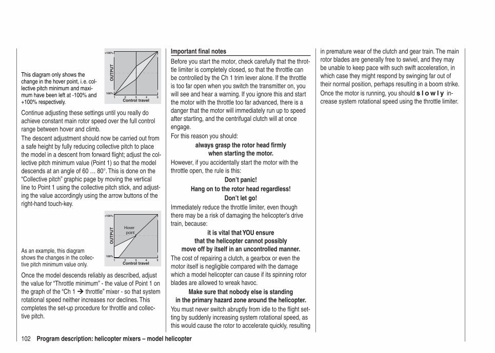
102 Program description: helicopter mixers – model helicopter
in premature wear of the clutch and gear train. The main rotor blades are generally free to swivel, and they may be unable to keep pace with such swift acceleration, in which case they might respond by swinging far out of their normal position, perhaps resulting in a boom strike.Once the motor is running, you should s l o w l y in-crease system rotational speed using the throttle limiter.
Important fi nal notesBefore you start the motor, check carefully that the throt-tle limiter is completely closed, so that the throttle can be controlled by the Ch 1 trim lever alone. If the throttle is too far open when you switch the transmitter on, you will see and hear a warning. If you ignore this and start the motor with the throttle too far advanced, there is a danger that the motor will immediately run up to speed after starting, and the centrifugal clutch will at once engage. For this reason you should:
always grasp the rotor head fi rmlywhen starting the motor.
However, if you accidentally start the motor with the throttle open, the rule is this:
Don’t panic!Hang on to the rotor head regardless!
Don’t let go!Immediately reduce the throttle limiter, even though there may be a risk of damaging the helicopter’s drive train, because:
it is vital that YOU ensurethat the helicopter cannot possibly
move off by itself in an uncontrolled manner.The cost of repairing a clutch, a gearbox or even the motor itself is negligible compared with the damage which a model helicopter can cause if its spinning rotor blades are allowed to wreak havoc.
Make sure that nobody else is standingin the primary hazard zone around the helicopter.
You must never switch abruptly from idle to the fl ight set-ting by suddenly increasing system rotational speed, as this would cause the rotor to accelerate quickly, resulting
This diagram only shows the change in the hover point, i. e. col-lective pitch minimum and maxi-mum have been left at -100% and +100% respectively.
+100%
100%
OU
TP
UT
2 3 4 51Control travel
Continue adjusting these settings until you really do achieve constant main rotor speed over the full control range between hover and climb.The descent adjustment should now be carried out from a safe height by fully reducing collective pitch to place the model in a descent from forward fl ight; adjust the col-lective pitch minimum value (Point 1) so that the model descends at an angle of 60 … 80°. This is done on the “Collective pitch” graphic page by moving the vertical line to Point 1 using the collective pitch stick, and adjust-ing the value accordingly using the arrow buttons of the right-hand touch-key.
As an example, this diagram shows the changes in the collec-tive pitch minimum value only.
+100%
100%
OU
TP
UT
2 3 4 51Control travel
Hoverpoint
Once the model descends reliably as described, adjust the value for “Throttle minimum” - the value of Point 1 on the graph of the “Ch 1 throttle” mixer - so that system rotational speed neither increases nor declines. This completes the set-up procedure for throttle and collec-tive pitch.

103For your notes
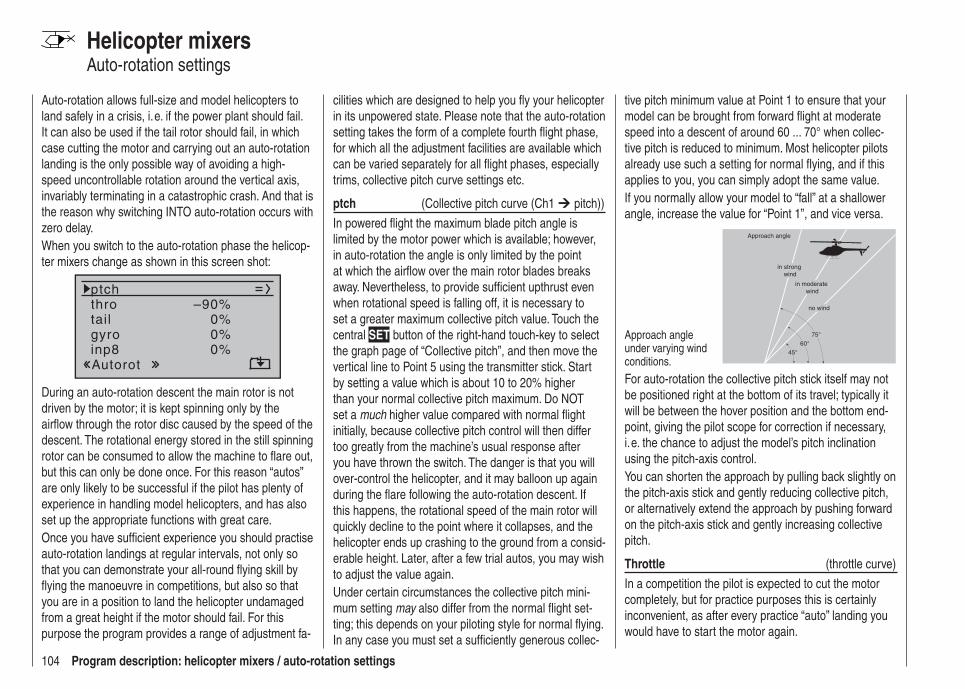
104 Program description: helicopter mixers / auto-rotation settings
Helicopter mixersAuto-rotation settings
Auto-rotation allows full-size and model helicopters to land safely in a crisis, i. e. if the power plant should fail. It can also be used if the tail rotor should fail, in which case cutting the motor and carrying out an auto-rotation landing is the only possible way of avoiding a high-speed uncontrollable rotation around the vertical axis, invariably terminating in a catastrophic crash. And that is the reason why switching INTO auto-rotation occurs with zero delay.When you switch to the auto-rotation phase the helicop-ter mixers change as shown in this screen shot:
tail
ptchthro
Autorot
gyro 0%inp8 0%
0%–90%
During an auto-rotation descent the main rotor is not driven by the motor; it is kept spinning only by the airfl ow through the rotor disc caused by the speed of the descent. The rotational energy stored in the still spinning rotor can be consumed to allow the machine to fl are out, but this can only be done once. For this reason “autos” are only likely to be successful if the pilot has plenty of experience in handling model helicopters, and has also set up the appropriate functions with great care.Once you have suffi cient experience you should practise auto-rotation landings at regular intervals, not only so that you can demonstrate your all-round fl ying skill by fl ying the manoeuvre in competitions, but also so that you are in a position to land the helicopter undamaged from a great height if the motor should fail. For this purpose the program provides a range of adjustment fa-
cilities which are designed to help you fl y your helicopter in its unpowered state. Please note that the auto-rotation setting takes the form of a complete fourth fl ight phase, for which all the adjustment facilities are available which can be varied separately for all fl ight phases, especially trims, collective pitch curve settings etc.
ptch (Collective pitch curve (Ch1 pitch))
In powered fl ight the maximum blade pitch angle is limited by the motor power which is available; however, in auto-rotation the angle is only limited by the point at which the airfl ow over the main rotor blades breaks away. Nevertheless, to provide suffi cient upthrust even when rotational speed is falling off, it is necessary to set a greater maximum collective pitch value. Touch the central SET button of the right-hand touch-key to select the graph page of “Collective pitch”, and then move the vertical line to Point 5 using the transmitter stick. Start by setting a value which is about 10 to 20% higher than your normal collective pitch maximum. Do NOT set a much higher value compared with normal fl ight initially, because collective pitch control will then differ too greatly from the machine’s usual response after you have thrown the switch. The danger is that you will over-control the helicopter, and it may balloon up again during the fl are following the auto-rotation descent. If this happens, the rotational speed of the main rotor will quickly decline to the point where it collapses, and the helicopter ends up crashing to the ground from a consid-erable height. Later, after a few trial autos, you may wish to adjust the value again.Under certain circumstances the collective pitch mini-mum setting may also differ from the normal fl ight set-ting; this depends on your piloting style for normal fl ying. In any case you must set a suffi ciently generous collec-
tive pitch minimum value at Point 1 to ensure that your model can be brought from forward fl ight at moderate speed into a descent of around 60 ... 70° when collec-tive pitch is reduced to minimum. Most helicopter pilots already use such a setting for normal fl ying, and if this applies to you, you can simply adopt the same value.If you normally allow your model to “fall” at a shallower angle, increase the value for “Point 1”, and vice versa.
Approach angle under varying wind conditions.
Approach angle
in moderate wind
no wind
45°
60°
75°
in strong wind
For auto-rotation the collective pitch stick itself may not be positioned right at the bottom of its travel; typically it will be between the hover position and the bottom end-point, giving the pilot scope for correction if necessary, i. e. the chance to adjust the model’s pitch inclination using the pitch-axis control.You can shorten the approach by pulling back slightly on the pitch-axis stick and gently reducing collective pitch, or alternatively extend the approach by pushing forward on the pitch-axis stick and gently increasing collective pitch.
Throttle (throttle curve)
In a competition the pilot is expected to cut the motor completely, but for practice purposes this is certainly inconvenient, as after every practice “auto” landing you would have to start the motor again.

105Program description: helicopter mixers / auto-rotation settings
For practice, then, you should set the value in this line so that the motor runs at a reliable idle during auto-rotation, but without the clutch engaging, so that you can open the throttle immediately to recover from an emergency; for an electric helicopter the motor should be reliably “off”.
Tail rotor (static torque compensation)
For normal fl ying the tail rotor is set up in such a way that it compensates for motor torque when the helicop-ter is hovering. This means that it already generates a certain amount of thrust even in its neutral position. The level of thrust is then varied by the tail rotor control system, and also by the various mixers which provide all manner of torque compensation, while the tail rotor trim is also used to compensate for varying weather condi-tions, fl uctuations in system rotational speed and other infl uences.However, in an auto-rotation descent the main rotor spins according to the windmill principle, i. e. it is not driven by the motor, and therefore there is no torque effect for which compensation is required, i. e. which the tail rotor would have to correct. For this reason all the appropriate mixers are automatically switched off in auto-rotation mode.However, the basic tail rotor setting therefore has to be different for auto-rotation, as the compensatory thrust described above is no longer required:Stop the motor and place the helicopter horizontal on the ground. With the transmitter and receiving system switched on, select the “Auto-rotation” fl ight phase. Fold both tail rotor blades down and change the blade pitch angle to zero degrees in the “Tail rotor” line. Viewed from the rear, the tail rotor blades should now lie parallel to each other.
Depending on the friction and running resistance of the gearbox, you may fi nd that the fuselage still yaws slightly in an auto-rotation descent. If necessary, the relatively slight torque which causes this effect must then be corrected by adjusting the tail rotor blade pitch angle. This value will always be a small fi gure between zero degrees and a pitch angle opposed to the direction of tail rotor pitch required for normal fl ight.
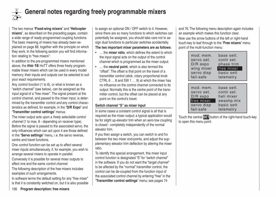
106 Program description: free mixers
General notes regarding freely programmable mixers
The two menus “Fixed-wing mixers” and “Helicopter mixers”, as described on the preceding pages, contain a wide range of ready-programmed coupling functions. The basic meaning of mixers has already been ex-plained on page 88, together with the principle on which they work. In the following section you will fi nd informa-tion relating to “free mixers”:In addition to the pre-programmed mixers mentioned above, the mx-16 HoTT offers three freely program-mable linear mixers which can be used in every model memory; their inputs and outputs can be selected to suit your exact requirements.Any control function (1 to 8), or what is known as a “switch channel” (see below), can be assigned as the input signal of a “free mixer”. The signal present at the control channel, and passed to the mixer input, is deter-mined by the transmitter control and any control charac-teristics as defi ned, for example, in the “D/R Expo” and “Transmitter control settings” menus.The mixer output acts upon a freely selectable control channel (1 to max. 8 - depending on receiver type). Before the signal is passed to the associated servo, the only infl uences which can act upon it are those defi ned in the “Servo settings” menu, i. e. the servo reverse, centre and travel functions.One control function can be set up to affect several mixer inputs simultaneously, if, for example, you wish to arrange several mixers to operate in parallel.Conversely it is possible for several mixer outputs to affect one and the same control channel.The following description of the free mixers includes examples of such arrangements.In software terms the default setting for any “free mixer” is that it is constantly switched on, but it is also possible
to assign an optional ON / OFF switch to it. However, since there are so many functions to which switches can potentially be assigned, you should take care not to as-sign dual functions to particular switches accidentally.The two important mixer parameters are as follows:
… the • mixer ratio, which defi nes the extent to which the input signal acts on the output of the control channel which is programmed as the mixer output.… the • neutral point, which is also termed the “offset”. The offset is that point on the travel of a transmitter control (stick, rotary proportional knob CTRL 6 … 8 and SW 1 … 9) at which the mixer has no infl uence on the control channel connected to its output. Normally this is the centre point of the trans-mitter control, but the offset can be placed at any point on the control’s travel.
Switch channel “S” as mixer inputIn some cases a constant control signal is all that is required as the mixer output; a typical application would be for slight up-elevator trim when an aero-tow coupling is closed - completely independently of the normal elevator trim.If you then assign a switch, you can switch to and fro between the two mixer end-points, and adjust the sup-plementary elevator trim defl ection by altering the mixer ratio.To identify this special arrangement, this mixer input control function is designated “S” for “switch channel” in the software. If you do not want the “target channel” to be affected by the “normal” transmitter control, the control can be de-coupled from the function input of the associated control channel by entering “free” in the “Transmitter control settings” menu; see pages 74
and 76. The following menu description again includes an example which makes this function clear.Now use the arrow buttons of the left or right-hand touch-key to leaf through to the “Free mixers” menu point of the multi-function menu:
mod. mem.servo set.D/R expowing mixer
base sett.contr set.phase tr imfree mixer
servo disp basic settfail-safe telemetry
mod. mem.servo set.D/R expofree mixer
base sett.contr set.heli mixerswashp.mix
servo disp basic settfail-safe telemetry
Touch the central SET button of the right-hand touch-key to open this menu point.
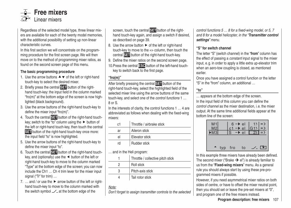
107Program description: free mixers
control functions 5 … 8 for a fi xed-wing model, or 5, 7 and 8 for a model helicopter, in the “Transmitter control settings” menu.
“S” for switch channelThe letter “S” (switch channel) in the “from” column has the effect of passing a constant input signal to the mixer input, e. g. in order to apply a little extra up-elevator trim when an aero-tow coupling is closed, as mentioned earlier.Once you have assigned a control function or the letter “S” in the “from” column, an additional …
“to” … appears at the bottom edge of the screen. In the input fi eld of this column you can defi ne the control channel as the mixer destination, i. e. the mixer output. At the same time additional fi elds appear at the bottom line of the screen:
typ fro to
M1M2M3
c1 el G16
el
el
S 2
1
In this example three mixers have already been defi ned. The second mixer (“Brake el”) is already familiar to us from the “Fixed-wing mixers” menu. As a general rule you should always start by using these pre-pro-grammed mixers if possible. However, if you need asymmetrical mixer ratios on both sides of centre, or have to offset the mixer neutral point, then you should set or leave the pre-set mixers at “0”, and program one of the free mixers instead.
Regardless of the selected model type, three linear mix-ers are available for each of the twenty model memories, with the additional possibility of setting up non-linear characteristic curves.In this fi rst section we will concentrate on the program-ming procedure for the fi rst screen page. We will then move on to the method of programming mixer ratios, as found on the second screen page of this menu.
The basic programming procedureUse the arrow buttons 1. of the left or right-hand touch-key to select the desired mixer.Briefl y press the central 2. SET button of the right-hand touch-key: the input fi eld in the column marked “fro(m)” at the bottom edge of the screen is now high-lighted (black background).Use the arrow buttons of the right-hand touch-key to 3. defi ne the mixer input “fro(m)”.Touch the central 4. SET button of the right-hand touch-key; switch to the “to” column using the button of the left or right-hand touch-key, then touch the central SET button of the right-hand touch-key once more: the input fi eld “to” is now highlighted.Use the arrow buttons of the right-hand touch-key to 5. defi ne the mixer input “to”.Touch the central 6. SET button of the right-hand touch-key, and (optionally) use the button of the left or right-hand touch-key to move to the column marked “Type” at the bottom edge of the screen; you can now include the Ch1 … Ch 4 trim lever for the mixer input signal (“Tr” for trim) …… and / or use the 7. arrow button of the left or right-hand touch-key to move to the column marked with the switch symbol at the bottom edge of the
Free mixersLinear mixers
screen, touch the central SET button of the right-hand touch-key again, and assign a switch if desired, as described on page 39.Use the arrow button8. of the left or right-hand touch-key to move to the => column, then touch the central SET button of the right-hand touch-key.Defi ne the mixer ratios on the second screen page.9. Press the central 10. ESC button of the left-hand touch-key to switch back to the fi rst page.
“fro(m)”After briefl y pressing the central SET button of the right-hand touch-key, select the highlighted fi eld of the selected mixer line using the arrow buttons of the same touch-key, and select one of the control functions 1 … 8 or S.In the interests of clarity, the control functions 1 … 4 are abbreviated as follows when dealing with the fi xed-wing mixers:
c1 Throttle / airbrake stick
ar Aileron stick
el Elevator stick
rd Rudder stick
… and in the Heli program:
1 Throttle / collective pitch stick
2 Roll stick
3 Pitch-axis stick
4 Tail rotor stick
Note:Don’t forget to assign transmitter controls to the selected

108 Program description: free mixers
Additional special features of free mixersIf you set up a mixer whose input is the same as its output, e. g. “c1 c1”, exotic results can be obtained in conjunction with the option of switching a free mixer on and off. You will fi nd one typical example of this on pages 152 … 154.Before we come to setting mixer ratios, we have to consider what happens if a mixer input is allowed to act on the pre-set coupling of aileron servos, fl ap servos or collective pitch servos:
Fixed-wing models:• Depending on the number of wing servos set in the “Aileron / Flap” line of the “Basic settings” menu, receiver outputs 2 and 5 are reserved for the aileron servos, and outputs 6 and 7 for the two fl ap servos, as special mixers are assigned to these functions.If mixer outputs are programmed to this type of cou-pled function, you have to consider their effect on the associated pair of wing fl aps, according to the “re-ceiving” control channel:
Mixer Wirkung
NN * 2 Servo pair 2 + 5 responds with aileron function
NN * 5 Servo pair 2 + 5 responds with fl ap function
NN * 6 Servo pair 6 + 7 responds with fl ap function
NN * 7 Servo pair 6 + 7 responds with aileron function
Model helicopters:• Depending on the type of helicopter, up to four ser-vos may be employed for collective pitch control; these will be connected to receiver outputs 1, 2, 3 and 5. The transmitter software links them together to provide the functions collective pitch, roll and pitch-axis.It is not advisable to mix one of the transmitter con-trols into these occupied channels using the free mix-ers available outside the “Heli mixers” menu, as you may inadvertently generate some extremely complex and unwanted interactions. “Collective pitch trim via a separate transmitter control” counts as one of the few exceptions to this rule; see example 2 at page 111.
Important note:When dealing with the interaction of multiple mixers on one control channel, it is essential to remember that the mixed travels of the individual mixers are cumulative when multiple stick commands are made simultaneously, and this brings a danger that the servo concerned may strike its mechanical end-stops. If you encounter this problem, simply reduce the servo travel in the “Servo settings” menu, and / or reduce the mixer values. However, if you do not wish to reduce the travels in this way, because this method would unnecessarily reduce the control travels you normally use, then you may prefer an alternative method of preventing the servos striking their end-stops: set a suitable travel limit in the “TRAVEL -/+” lines of the “RX SERVO” display page of the “Telemetry” menu.
Erasing mixersIf you need to erase a mixer that you have already defi ned, use the arrow buttons of the left or right-hand touch-key to select its line, then use the arrow but-tons to move to the “from” column before touching the central SET button of the right-hand touch-key. The fi eld in the “from” column of the mixer to be erased is now highlighted: simultaneously touch the two arrow but-tons or of the right-hand touch-key (CLEAR).
Mixer switchesIn our example above, a physical switch “2” and the control switch “C1” have been assigned to the two linear mixers 1 and 2, and switch “3” to mixer 3. The switch symbol to the right of the switch number shows the current status of that switch.
Any mixer to which no switch has been assigned in the column marked by the switch symbol at the bottom of the screen is permanently switched on.
“Type” (including the trim)
If you wish, and if you are using one of the primary control functions 1 … 4, you can set the trim value of the digital trim lever for the associated stick to affect the mixer input. This is accomplished by touching the central SET button of the right-hand touch-key, then using its arrow buttons to select “Tr” in the highlighted fi eld.
Note:The effect of the Ch 1 trim lever on the mixer output var-ies according to the function which has been assigned to it in the “Basic settings” menu (pages 56 and 64) in the “Motor at Ch 1” column for fi xed-wing models.
* NN = Nomen Nominandum (name to be stated)
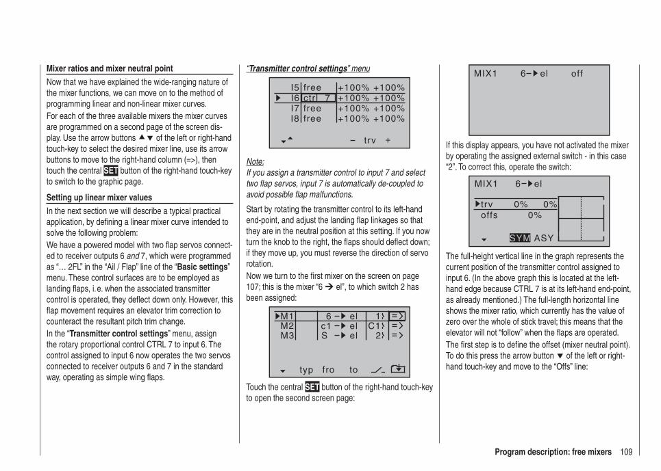
109Program description: free mixers
“Transmitter control settings” menu
I5I6I7
+trv
I8
ctr l 7freefree
+100% +100%+100%
+100% +100%+100% +100%
+100%free
Note:If you assign a transmitter control to input 7 and select two fl ap servos, input 7 is automatically de-coupled to avoid possible fl ap malfunctions.
Start by rotating the transmitter control to its left-hand end-point, and adjust the landing fl ap linkages so that they are in the neutral position at this setting. If you now turn the knob to the right, the fl aps should defl ect down; if they move up, you must reverse the direction of servo rotation.Now we turn to the fi rst mixer on the screen on page 107; this is the mixer “6 el”, to which switch 2 has been assigned:
typ fro to
M1M2M3
c1 el C16
el
el
S
1
2
Touch the central SET button of the right-hand touch-key to open the second screen page:
Mixer ratios and mixer neutral pointNow that we have explained the wide-ranging nature of the mixer functions, we can move on to the method of programming linear and non-linear mixer curves.For each of the three available mixers the mixer curves are programmed on a second page of the screen dis-play. Use the arrow buttons of the left or right-hand touch-key to select the desired mixer line, use its arrow buttons to move to the right-hand column (=>), then touch the central SET button of the right-hand touch-key to switch to the graphic page.
Setting up linear mixer valuesIn the next section we will describe a typical practical application, by defi ning a linear mixer curve intended to solve the following problem:We have a powered model with two fl ap servos connect-ed to receiver outputs 6 and 7, which were programmed as “… 2FL” in the “Ail / Flap” line of the “Basic settings” menu. These control surfaces are to be employed as landing fl aps, i. e. when the associated transmitter control is operated, they defl ect down only. However, this fl ap movement requires an elevator trim correction to counteract the resultant pitch trim change.In the “Transmitter control settings” menu, assign the rotary proportional control CTRL 7 to input 6. The control assigned to input 6 now operates the two servos connected to receiver outputs 6 and 7 in the standard way, operating as simple wing fl aps.
MIX1 6 el off
If this display appears, you have not activated the mixer by operating the assigned external switch - in this case “2”. To correct this, operate the switch:
MIX1 6 el
trv 0% 0%0%offs
ASYSYM
The full-height vertical line in the graph represents the current position of the transmitter control assigned to input 6. (In the above graph this is located at the left-hand edge because CTRL 7 is at its left-hand end-point, as already mentioned.) The full-length horizontal line shows the mixer ratio, which currently has the value of zero over the whole of stick travel; this means that the elevator will not “follow” when the fl aps are operated.The fi rst step is to defi ne the offset (mixer neutral point). To do this press the arrow button of the left or right-hand touch-key and move to the “Offs” line:

110 Program description: free mixers
MIX1 6 el
trv 0% 0%0%offs
SELSTO
The dotted vertical line indicates the position of the mixer neutral point (“offset”), i. e. that point along the control travel at which the mixer has NO infl uence on the channel connected to its output. By default this point is set to the centre position.However, in our example the neutral (retracted) position of the fl aps is located at the left-hand end-stop of the rotary proportional control, and in this position the eleva-tor must not be affected. We therefore have to shift the mixer neutral point exactly to that position. If you have not already done so, turn the control - in our example this is CTRL 7 - to the left-hand end-stop and touch the central SET button of the right-hand touch-key. The dot-ted vertical line now moves to this point - the new mixer neutral point - which always retains the “OUTPUT” value of zero in accordance with the mixer defi nition.As it happens, this setting is diffi cult to show in a screen shot, so we will change the “offset” value to only -75%.
MIX1 6 el
trv 0% 0%–75%offs
SELSTO
Notes:If you wish, you can move the offset value back to • centre or otherwise adjust it as follows: select SEL using the arrow button of the left or right-hand touch-key, followed by briefl y pressing the central SET button of the right-hand touch-key; you can now use the arrow buttons of the left or right-hand touch-key to move the offset value.You can also return the mixer neutral point to cen-• tre automatically as follows: select SEL using the ar-row button of the left or right-hand touch-key, then simultaneously press the two arrow buttons or
of the right-hand touch-key (CLEAR).
Symmetrical mixer ratiosThe next step is to defi ne the mixer values above and below the mixer neutral point, starting from its current position. Use the arrow button of the left or right-hand touch-key to move to the “Travel” line: if necessary, use the arrow buttons of the left or right-hand touch-key to select the SYM fi eld, so that you can set the mixer value symmetrically relative to the offset point you have just programmed. Touch the central SET button of the right-hand touch-key, then set the values in the two highlighted fi elds within the range -150% to +150% using the arrow buttons of the right-hand touch-key. Remember that the set mixer value always refers to the input signal from the associated transmitter control (control signal)! Setting a negative mixer value reverses the direction of the mixer.Simultaneously pressing the two arrow buttons or
of the right-hand touch-key (CLEAR) erases the mixer ratio in the highlighted fi eld.The “optimum” value for our purposes will inevitably
need to be established through a fl ight testing pro-gramme.
MIX1 6 el
trv +20% +20%–75%offs
ASYSYM
Since we previously set the mixer neutral point to -75% of control travel, the elevator (“el”) will already exhibit a (slight) “down-elevator effect” at the neutral point of the landing fl aps, and this, of course, is not wanted. To cor-rect this we shift the mixer neutral point back to -100% of control travel, as described earlier.
MIX1 6 el
trv +20% +20%–100%offs
SELSTO
If you were now to reset the offset from -75% to, say, 0% control travel, by selecting the SEL fi eld using the arrow buttons of the left or right-hand touch-key, and then briefl y pressing the two arrow buttons or of the right-hand touch-key (CLEAR) simultaneously, the screen would look like this:
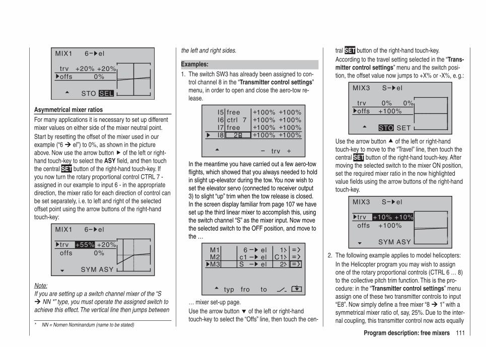
111Program description: free mixers* NN = Nomen Nominandum (name to be stated)
MIX1 6 el
trv +20% +20%0%offs
STO SEL
Asymmetrical mixer ratiosFor many applications it is necessary to set up different mixer values on either side of the mixer neutral point.Start by resetting the offset of the mixer used in our example (“6 el”) to 0%, as shown in the picture above. Now use the arrow button of the left or right-hand touch-key to select the ASY fi eld, and then touch the central SET button of the right-hand touch-key. If you now turn the rotary proportional control CTRL 7 - assigned in our example to input 6 - in the appropriate direction, the mixer ratio for each direction of control can be set separately, i. e. to left and right of the selected offset point using the arrow buttons of the right-hand touch-key:
MIX1 6 el
trv +20%0%offs
SYM ASY
+55%
Note:If you are setting up a switch channel mixer of the “S
NN *” type, you must operate the assigned switch to achieve this effect. The vertical line then jumps between
the left and right sides.
Examples:The switch SW3 has already been assigned to con-1. trol channel 8 in the “Transmitter control settings” menu, in order to open and close the aero-tow re-lease.
I5I6I7
+trv
100% 100%100% 100%100% 100%
2
+ ++ ++ +
I8 100% 100%+ +
ctr l 7free
free
In the meantime you have carried out a few aero-tow fl ights, which showed that you always needed to hold in slight up-elevator during the tow. You now wish to set the elevator servo (connected to receiver output 3) to slight “up” trim when the tow release is closed. In the screen display familiar from page 107 we have set up the third linear mixer to accomplish this, using the switch channel “S” as the mixer input. Now move the selected switch to the OFF position, and move to the …
typ fro to
M1M2M3
c1 el C16
el
el
S
1
2
… mixer set-up page.Use the arrow button of the left or right-hand touch-key to select the “Offs” line, then touch the cen-
tral SET button of the right-hand touch-key.According to the travel setting selected in the “Trans-mitter control settings” menu and the switch posi-tion, the offset value now jumps to +X% or -X%, e. g.:
MIX3 S el
trv 0% 0%+100%offs
SETSTO
Use the arrow button of the left or right-hand touch-key to move to the “Travel” line, then touch the central SET button of the right-hand touch-key. After moving the selected switch to the mixer ON position, set the required mixer ratio in the now highlighted value fi elds using the arrow buttons of the right-hand touch-key.
MIX3 S el
trv+100%offs
ASYSYM
+10% +10%
The following example applies to model helicopters:2. In the Helicopter program you may wish to assign one of the rotary proportional controls (CTRL 6 … 8) to the collective pitch trim function. This is the pro-cedure: in the “Transmitter control settings” menu assign one of these two transmitter controls to input “E8”. Now simply defi ne a free mixer “8 1” with a symmetrical mixer ratio of, say, 25%. Due to the inter-nal coupling, this transmitter control now acts equally
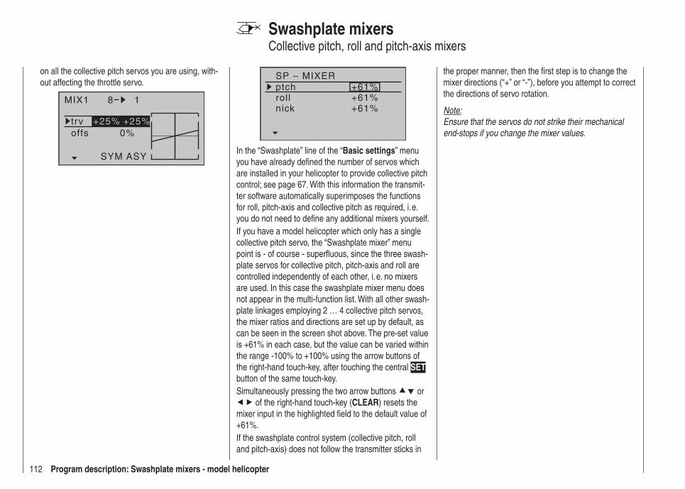
112 Program description: Swashplate mixers - model helicopter
SP – MIXERptchrollnick
+61%+61%+61%
In the “Swashplate” line of the “Basic settings” menu you have already defi ned the number of servos which are installed in your helicopter to provide collective pitch control; see page 67. With this information the transmit-ter software automatically superimposes the functions for roll, pitch-axis and collective pitch as required, i. e. you do not need to defi ne any additional mixers yourself.If you have a model helicopter which only has a single collective pitch servo, the “Swashplate mixer” menu point is - of course - superfl uous, since the three swash-plate servos for collective pitch, pitch-axis and roll are controlled independently of each other, i. e. no mixers are used. In this case the swashplate mixer menu does not appear in the multi-function list. With all other swash-plate linkages employing 2 … 4 collective pitch servos, the mixer ratios and directions are set up by default, as can be seen in the screen shot above. The pre-set value is +61% in each case, but the value can be varied within the range -100% to +100% using the arrow buttons of the right-hand touch-key, after touching the central SET button of the same touch-key.Simultaneously pressing the two arrow buttons or
of the right-hand touch-key (CLEAR) resets the mixer input in the highlighted fi eld to the default value of +61%.If the swashplate control system (collective pitch, roll and pitch-axis) does not follow the transmitter sticks in
Swashplate mixersCollective pitch, roll and pitch-axis mixers
the proper manner, then the fi rst step is to change the mixer directions (“+” or “-”), before you attempt to correct the directions of servo rotation.
Note:Ensure that the servos do not strike their mechanical end-stops if you change the mixer values.
on all the collective pitch servos you are using, with-out affecting the throttle servo.
MIX1 8 1
trv +25% +25%0%offs
ASYSYM

113Program description: servo position
Servo display
Use the arrow buttons of the left or right-hand touch-key to leaf through to the “Servo display” menu point of the multi-function menu:
mod.mem.servo set.D/R expowing mixer
base sett.contr set.phase tr imfree mixerbasic sett
fail-safe telemetryservo disp
Open the menu point by touching the central SET button of the right-hand touch-key.However, this visual display of the current servo posi-tions can be called up not only by selecting this menu, but also directly by simultaneously pressing the buttons
of the left-hand touch-key from the transmitter’s basic display, and also from almost any menu position. Touching the central ESC button of the left-hand touch-key returns you to your starting point again.
1
3
5
7
2
4
6
8
0%
0%
0%
–100%
0%
0%
0%
+100%
The current position of any servo is displayed in bar-chart form, which takes into account the transmitter con-trol and servo settings, the Dual-Rate / Expo functions, the interaction of all active mixers etc., within the range -150% to +150% of normal travel. 0% corresponds exactly to the servo centre position. The servo display provides a quick method of checking your settings, with-out having to switch on the receiving system. However,
this does not relieve you of the need to check all your programming steps carefully on the model before oper-ating it for the fi rst time, as this is the only safe method of excluding possible programming errors.
The display is based on the following scheme for fi xed-wing models:
Bar 1 = throttle / brake servoBar 2 = aileron or left aileronBar 3 = elevatorBar 4 = rudderBar 5 = right aileronBar 6 = (left) fl ap / free channelBar 7 = right fl ap / free channelBar 8 = free channel / second elevator servo
and for model helicopters:Bar 1 = collective pitch or roll (2) or pitch-axis (2) ser-
voBar 2 = roll (1) servoBar 3 = pitch-axis (1) servoBar 4 = tail rotor servo (gyro)Bar 5 = pitch-axis (2) servo / free channelBar 6 = throttle servo or speed controllerBar 7 = gyro gain / free channelBar 8 = speed governor / free channel
Note:Please bear in mind that the servo display refers exclu-sively to the original servo sequence, i. e. it does NOT take into account any output swapping, as can be car-ried out in the “Receiver output” sub-menu in the “Basic settings” menu, page 60 / 69.
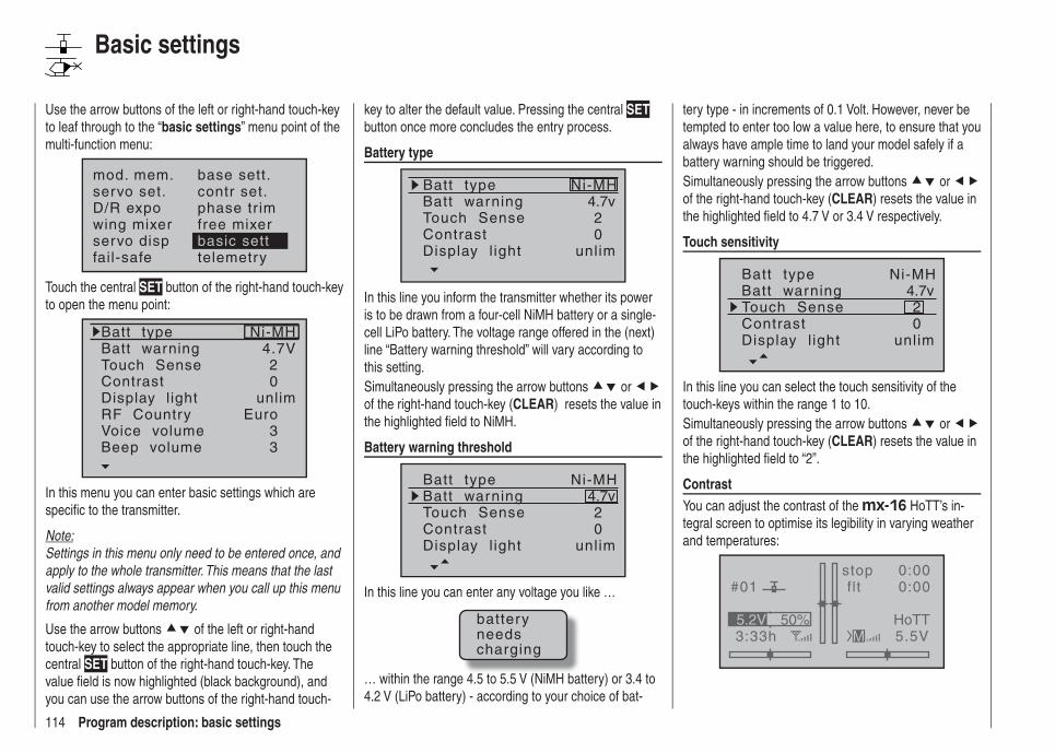
114 Program description: basic settings
Use the arrow buttons of the left or right-hand touch-key to leaf through to the “basic settings” menu point of the multi-function menu:
mod. mem.servo set.D/R expowing mixer
base sett.contr set.phase tr imfree mixer
servo disp basic settfail-safe telemetry
Touch the central SET button of the right-hand touch-key to open the menu point:
Batt typeBatt warningTouch SenseContrast
Ni-MH
Display l ightRF CountryVoice volume
24.7V
0
Euro3
unlim
Beep volume 3
In this menu you can enter basic settings which are specifi c to the transmitter.
Note:Settings in this menu only need to be entered once, and apply to the whole transmitter. This means that the last valid settings always appear when you call up this menu from another model memory.
Use the arrow buttons of the left or right-hand touch-key to select the appropriate line, then touch the central SET button of the right-hand touch-key. The value fi eld is now highlighted (black background), and you can use the arrow buttons of the right-hand touch-
key to alter the default value. Pressing the central SET button once more concludes the entry process.
Battery type
Batt typeBatt warning
ContrastTouch Sense
4.7v
02
Ni-MH
Display l ight unlim
In this line you inform the transmitter whether its power is to be drawn from a four-cell NiMH battery or a single-cell LiPo battery. The voltage range offered in the (next) line “Battery warning threshold” will vary according to this setting.Simultaneously pressing the arrow buttons or of the right-hand touch-key (CLEAR) resets the value in the highlighted fi eld to NiMH.
Battery warning threshold
Batt typeBatt warning
ContrastTouch Sense
4.7v
02
Ni-MH
Display l ight unlim
In this line you can enter any voltage you like …
batteryneedscharging
… within the range 4.5 to 5.5 V (NiMH battery) or 3.4 to 4.2 V (LiPo battery) - according to your choice of bat-
tery type - in increments of 0.1 Volt. However, never be tempted to enter too low a value here, to ensure that you always have ample time to land your model safely if a battery warning should be triggered.Simultaneously pressing the arrow buttons or of the right-hand touch-key (CLEAR) resets the value in the highlighted fi eld to 4.7 V or 3.4 V respectively.
Touch sensitivity
Batt typeBatt warning
ContrastTouch Sense
4.7v
02
Ni-MH
Display l ight unlim
In this line you can select the touch sensitivity of the touch-keys within the range 1 to 10.Simultaneously pressing the arrow buttons or of the right-hand touch-key (CLEAR) resets the value in the highlighted fi eld to “2”.
ContrastYou can adjust the contrast of the mx-16 HoTT’s in-tegral screen to optimise its legibility in varying weather and temperatures:
#01
3:33h
stop flt
0:000:00
5.5V50%5.2V HoTT
M
Basic settings
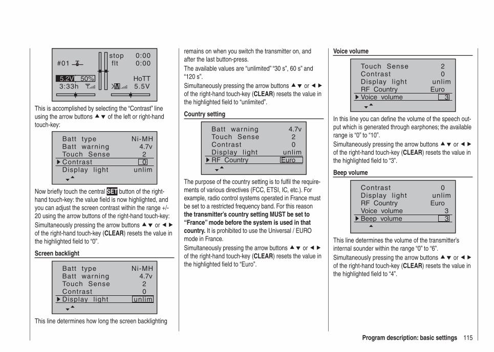
115Program description: basic settings
#01
3:33h
stop flt
0:000:00
5.5V50%5.2V HoTT
M
This is accomplished by selecting the “Contrast” line using the arrow buttons of the left or right-hand touch-key:
Batt typeBatt warning
ContrastTouch Sense
4.7v
02
Ni-MH
Display l ight unlim
Now briefl y touch the central SET button of the right-hand touch-key: the value fi eld is now highlighted, and you can adjust the screen contrast within the range +/- 20 using the arrow buttons of the right-hand touch-key:Simultaneously pressing the arrow buttons or of the right-hand touch-key (CLEAR) resets the value in the highlighted fi eld to “0”.
Screen backlight
Batt typeBatt warning
ContrastTouch Sense
4.7v
02
Ni-MH
Display l ight unlim
This line determines how long the screen backlighting
remains on when you switch the transmitter on, and after the last button-press.The available values are “unlimited” “30 s”, 60 s” and “120 s”.Simultaneously pressing the arrow buttons or of the right-hand touch-key (CLEAR) resets the value in the highlighted fi eld to “unlimited”.
Country setting
Batt warning
ContrastTouch Sense
4.7v
02
Display l ight unlimRF Country Euro
The purpose of the country setting is to fulfi l the require-ments of various directives (FCC, ETSI, IC, etc.). For example, radio control systems operated in France must be set to a restricted frequency band. For this reason the transmitter’s country setting MUST be set to “France” mode before the system is used in that country. It is prohibited to use the Universal / EURO mode in France.Simultaneously pressing the arrow buttons or of the right-hand touch-key (CLEAR) resets the value in the highlighted fi eld to “Euro”.
Voice volume
ContrastTouch Sense
02
Display l ight unlimRF Country EuroVoice volume 3
In this line you can defi ne the volume of the speech out-put which is generated through earphones; the available range is “0” to “10”.Simultaneously pressing the arrow buttons or of the right-hand touch-key (CLEAR) resets the value in the highlighted fi eld to “3”.
Beep volume
Contrast 0Display l ight unlimRF Country EuroVoice volume 3Beep volume 3
This line determines the volume of the transmitter’s internal sounder within the range “0” to “6”.Simultaneously pressing the arrow buttons or of the right-hand touch-key (CLEAR) resets the value in the highlighted fi eld to “4”.
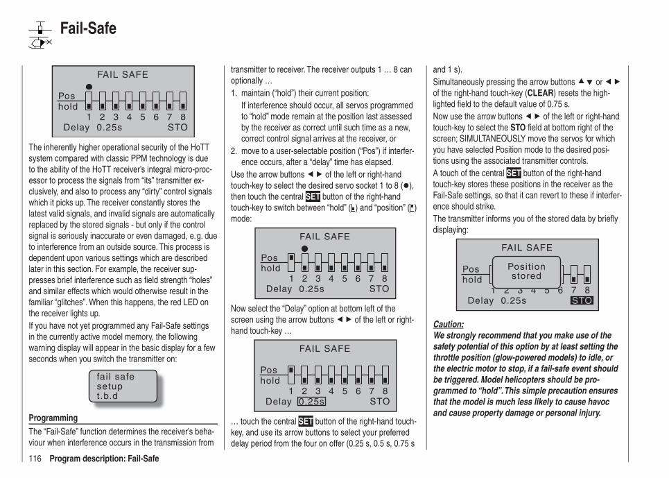
116 Program description: Fail-Safe
FAIL SAFE
Poshold
1 2 3 4 5 6 7 8Delay 0.25s STO
The inherently higher operational security of the HoTT system compared with classic PPM technology is due to the ability of the HoTT receiver’s integral micro-proc-essor to process the signals from “its” transmitter ex-clusively, and also to process any “dirty” control signals which it picks up. The receiver constantly stores the latest valid signals, and invalid signals are automatically replaced by the stored signals - but only if the control signal is seriously inaccurate or even damaged, e. g. due to interference from an outside source. This process is dependent upon various settings which are described later in this section. For example, the receiver sup-presses brief interference such as fi eld strength “holes” and similar effects which would otherwise result in the familiar “glitches”. When this happens, the red LED on the receiver lights up.If you have not yet programmed any Fail-Safe settings in the currently active model memory, the following warning display will appear in the basic display for a few seconds when you switch the transmitter on:
fai l safesetupt.b.d
ProgrammingThe “Fail-Safe” function determines the receiver’s beha-viour when interference occurs in the transmission from
transmitter to receiver. The receiver outputs 1 … 8 can optionally …
maintain (“hold”) their current position:1. If interference should occur, all servos programmed to “hold” mode remain at the position last assessed by the receiver as correct until such time as a new, correct control signal arrives at the receiver, ormove to a user-selectable position (“Pos”) if interfer-2. ence occurs, after a “delay” time has elapsed.
Use the arrow buttons of the left or right-hand touch-key to select the desired servo socket 1 to 8 ( ), then touch the central SET button of the right-hand touch-key to switch between “hold” ( ) and “position” ( ) mode:
FAIL SAFE
Pos
1 2 3 4 5 6 7 8STO
hold
Delay 0.25s
Now select the “Delay” option at bottom left of the screen using the arrow buttons of the left or right-hand touch-key …
FAIL SAFE
Pos
1 2 3 4 5 6 7 8STO
hold
Delay 0.25s
… touch the central SET button of the right-hand touch-key, and use its arrow buttons to select your preferred delay period from the four on offer (0.25 s, 0.5 s, 0.75 s
and 1 s).Simultaneously pressing the arrow buttons or of the right-hand touch-key (CLEAR) resets the high-lighted fi eld to the default value of 0.75 s.Now use the arrow buttons of the left or right-hand touch-key to select the STO fi eld at bottom right of the screen; SIMULTANEOUSLY move the servos for which you have selected Position mode to the desired posi-tions using the associated transmitter controls.A touch of the central SET button of the right-hand touch-key stores these positions in the receiver as the Fail-Safe settings, so that it can revert to these if interfer-ence should strike.The transmitter informs you of the stored data by briefl y displaying:
FAIL SAFE
Pos
1 2 3 4 5 6 7 8STO
Posit ionstoredhold
Delay 0.25s
Caution:We strongly recommend that you make use of the safety potential of this option by at least setting the throttle position (glow-powered models) to idle, or the electric motor to stop, if a fail-safe event should be triggered. Model helicopters should be pro-grammed to “hold”. This simple precaution ensures that the model is much less likely to cause havoc and cause property damage or personal injury.
Fail-Safe

117Program description: Telemetry menu
Telemetry
The “Telemetry” menu is used to call up and program transmitter and receiver data, and data generated by optional telemetry sensors (see Appendix), in real time.
Note:If you register your product under http://www.graupner.de/en/service/product_registration you will automatically be informed about new updates by e-mail.
Receiver data are transmitted to the transmitter via the HoTT receiver’s integral downlink channel. Please note the following important points in this regard:
Important information:These instructions cover the functions available at • the time of going to press.As mentioned in the sections entitled “Binding mul-• tiple receivers” on pages 61 and 70, it is possible to bind more than one receiver per model. However, in subsequent operations only the receiver which was bound last is able to make a telemetry con-nection to the transmitter. On the other hand, this also means that only the last bound receiver can be addressed using the Telemetry menu. You may there-fore need to change the binding sequence before you can enter settings which relate to a particular receiv-er.When setting up the radio control system, please • ensure at all times that the transmitter aerial is an adequate distance from the receiver aerials. A safe distance is about one metre. If you ne-glect this, you risk interference with the downlink channel, and consequent malfunctions.Since the transmitter and receiver only exchange te-• lemetry data after each fourth data packet, data transmission inevitably requires a certain amount of
time, which means that there will be some delay in responding to button-presses and set-up changes. This does not constitute an error.Changes to model and sensor programming must • only be carried out when the model is on the ground. Do not make any alterations unless the motor is switched off and the fl ight battery is disconnected. If you ignore this, unwanted effects of programming changes cannot be excluded.For example, if you accidentally initiate an active ser-vo test at the receiver, the model could crash and cause personal injury or property damage. Please see the Safety Notes on pages 3 … 6 of this manual and the various individual instructions.All settings which you enter using the “• Telemetry” menu, such as Fail-Safe, servo direction, servo trav-el, mixer and curve settings etc., are stored exclu-sively in the receiver, and are therefore carried over if you install the receiver in a different model. For this reason we strongly recommend that you re-initial-ise your HoTT receiver if you wish to use it in another model; see “Reset” on page 32 and 33.We therefore recommend that you program directions • of servo rotation, servo travel, mixer and curve set-tings using only the mx-16-specifi c standard men-us “Servo settings” (page 72), “Free mixers” (page 107) and “D/R Expo” (pages 82 and 84). If you ignore this, the settings may overlap and interfere with each other; in the most favourable case this can result in confusion when operating the model, and in the least favourable case it could cause problems.The channel-mapping function of the • mx-16 HoTT’s integral “Telemetry” menu can be used to share out control functions between multiple receiv-
ers in any way, or even to assign the same control function to several receiver outputs; for example, you may wish to operate each aileron with two servos in-stead of just one, etc. Once again we strongly re-commend that you act as cautiously as possible when carrying out the programming.
One telemetry sensor can be connected to the Tele-metry input of the following receivers: GR-12S HoTT (Order No. 33505), GR-12 HoTT (Order No. 33506) and GR-16 (Order No. 33508). Two telemetry sensors can be connected to the HoTT GR-24 HoTT receiver (Order No. 33512).Since the system can be updated by the user, the as-sociated “Telemetry” menus can constantly be kept up-to-date, and expanded with the introduction of additional functions or languages in future.Before updating the transmitter software you should always back up all occupied model memories to a compatible laptop or PC using a standard commercially available fi ve-pole mini-USB lead, in order to avoid a possible loss of data.In addition to the back-ups mentioned above, fi rmware updates are transferred using the mini-USB port located on the back of the transmitter, in conjunction with a PC running the Windows XP, Vista or 7 operating system.The programs required for this and related information can be found in the Download area for the correspond-ing products at the website www.graupner.de. We always recommend that you load the latest fi rmware into your equipment, to ensure that your system is constantly kept up-to-date.
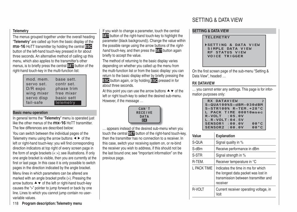
118 Program description: Telemetry menu
TelemetryThe menus grouped together under the overall heading “Telemetry” are called up from the basic display of the mx-16 HoTT transmitter by holding the central ESC button of the left-hand touch-key pressed in for about three seconds. An alternative method of calling up this menu, which also applies to the transmitter’s other menus, is to briefl y press the central SET button of the right-hand touch-key in the multi-function list:
mod. mem.servo set.D/R expowing mixer
base sett.contr set.phase tr imfree mixer
servo disp basic settfail-safe telemetry
Basic menu operationIn general terms the “Telemetry” menu is operated just like the other menus of the mx-16 HoTT transmitter. The few differences are described below:You can switch between the individual pages of the Telemetry menu using the arrow buttons of the left or right-hand touch-key: you will fi nd corresponding direction indicators at top right of every screen page in the form of angle brackets (< >); see illustrations. If only one angle bracket is visible, then you are currently at the fi rst or last page. In this case it is only possible to switch pages in the direction indicated by the angle bracket.Menu lines in which parameters can be altered are marked with an angle bracket prefi x (>). Pressing the arrow buttons of the left or right-hand touch-key causes the “>” pointer to jump forward or back by one line. Lines to which you cannot jump contain no user-variable values.
If you wish to change a parameter, touch the central SET button of the right-hand touch-key to highlight the parameter (black background)). Change the value within the possible range using the arrow buttons of the right-hand touch-key, and then press the SET button again briefl y to accept the value.The method of returning to the basic display varies depending on whether you called up the menu from the multi-function list or from the basic display: you can return to the basic display either by briefl y pressing the ESC button again, or by holding ESC pressed in for about three seconds.At this point you can use the arrow buttons of the left or right touch-key to select the desired sub-menu. However, if the message …
CAN‘TRECEIVEDATAOK
… appears instead of the desired sub-menu when you touch the central SET button of the right-hand touch-key, then the transmitter has no connection to a receiver. In this case, switch your receiving system on, or re-bind the receiver you wish to address, if this should not be the last bound one; see “Important information” on the previous page.
SETTING & DATA VIEW
TELEMETRY
SETTING & DATA VIEWSIMPLE DATA VIEWRF STATUS VIEWVOICE TRIGGER
On the fi rst screen page of the sub-menu “Setting & Data View”, headed …
RX DATAVIEW… you cannot enter any settings. This page is for infor-mation purposes only:
RX DATAVIEW
S–STR100% R–TEM.+28°CL PACK TIME 00010msecR-VOLT :05.0VL.R-VOLT:04.5V
S–QUA100%S–dBM–030dBM
SENSOR1 :00.0V 00°CSENSOR2 :00.0V 00°C
Value Explanation
S-QUA Signal quality in %
S-dBm Receive performance in dBm
S-STR Signal strength in %
R-TEM. Receiver temperature in °C
L PACK TIME Indicates the time in ms for which the longest data packet was lost in transmission between transmitter and receiver
R-VOLT Current receiver operating voltage, in Volt
SETTING & DATA VIEW
119Program description: Telemetry menu
L.R-VOLT Lowest receiver operating voltage since the last power-on, in Volt
SENSOR1 Shows the values of the optional telemetry sensor 1 in Volt and °C
SENSOR2 Shows the values of the optional telemetry sensor 2 in Volt and °C
Signal quality (S-QUA)The signal quality (S-QUA) is sent “live” to the transmit-ter via the receiver’s downlink channel, and shows the signal strength in %.
Receive performance (S-dBm)The receive performance (S-dBm) is displayed as a negative value, i. e. a value approaching zero is the highest value (= best reception). The lower the value falls, the worse is the receive performance. This is an important item of information, particularly when you are carrying out a range-check before operating the model.
Note:In the case of negative numbers the value is reversed: the higher the number following the minus sign, the lower the value.
Carry out a range-check as described on pages 62 and 70 before every fl ight, and remember to simulate all the servo movements which are likely to occur in the air. In active range-check mode the range must be at least fi fty metres on the ground. To guarantee safe operation of your model, a value no higher than -80 dBm must be displayed in the “RX DATA” display under “S-dBm” at this distance. If the value falls below this (e. g. -85 dBm), you should under no circumstances fl y your model. Instead check the receiving system installation and the aerial positions.
When operating a model this value should not fall below -90 dBm; if it does, reduce the distance between the pilot and the model. However, the audible range warn-ing (beeping at one-second intervals) will normally be triggered before this value is reached, in order to ensure safe operation.
Signal strength (S-STR)The value for signal strength (S-STR) is displayed in %. An audible range warning (beeping at one-second inter-vals) will always be generated as soon as the receiver signal in the downlink channel is too weak. However, since the transmitter has a much higher transmitting power than the receiver, the model can still be operated safely at this point. Nevertheless, in the interests of safety the distance to the model should be reduced until the audible warning ceases.
Receiver temperature (R-TEM.)Ensure under all fl ight conditions that the receiver stays within its specifi ed temperature range (ideally between -10 and +55°C).The limit values for receiver temperature after which a warning occurs can be set in the “SERVO TEST” sub-menu under “ALARM TEMP+” (50 … 80°C) and “ALARM TEMP-” (-20 … +10°C). If the temperature exceeds or falls below the set limit, an audible signal (continuous beeping) is triggered, and “TEMP.E” is displayed at top right in all the “RX” receiver sub-menus. At the same time the “R-TEM“ parameter is highlighted on the “RX DATAVIEW” screen page.
Data packets (L PACK TIME)This displays the longest period in ms in which data packets were lost in transmission from the transmitter to the receiver. In practice this means the longest time in
which the radio control system went into Fail-Safe mode.
Operating voltage (R-VOLT)Check the receiver’s operating voltage constantly. If it is too low, you must under no circumstances continue to operate your model, and certainly not launch it.The low receiver voltage warning can be adjusted within the range 3.0 to 6.0 Volt in the “SERVO TEST” sub-menu under “ALARM VOLT”. If the voltage falls below the threshold, an audible signal (repeated double beep, long / short) is generated, and in all the receiver sub-menus “RX …” you will see “VOLT.E” at top right. At the same time the parameter “R-VOLT” is highlighted in the “RX DATAVIEW” sub-menu.The current receiver battery voltage is also shown in the basic display; see page 24.
Minimum operating voltage (L.R-VOLT)“L.R-VOLT” shows the receiver’s minimum operating voltage since the last time it was switched on. If this voltage differs signifi cantly from the current operating voltage “R-VOLT”, this could mean that the receiver battery is being overstressed by the servos, causing collapses in battery voltage. If this should occur, we recommend installing a higher-performance receiver battery to ensure maximum operating safety.
Sensor 1 + 2Shows the values of the optional telemetry sensor 1 and, if present, sensor 2 in Volt and °C. You will fi nd a description of these sensors in the Appendix.
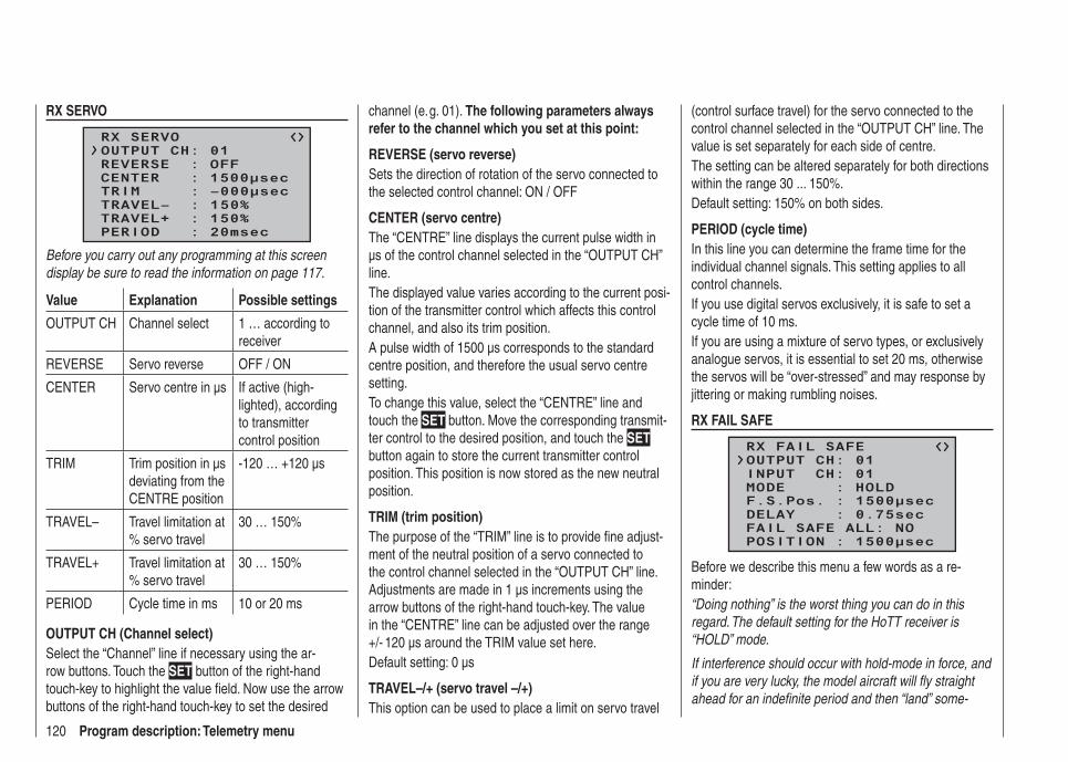
120 Program description: Telemetry menu
RX SERVO
RX SERVO
REVERSE : OFFCENTER : 1500μsecTRIM : –000μsecTRAVEL– : 150%
OUTPUT CH: 01
TRAVEL+ : 150%PERIOD : 20msec
Before you carry out any programming at this screen display be sure to read the information on page 117.
Value Explanation Possible settings
OUTPUT CH Channel select 1 … according to receiver
REVERSE Servo reverse OFF / ON
CENTER Servo centre in µs If active (high-lighted), according to transmitter control position
TRIM Trim position in µs deviating from the CENTRE position
-120 … +120 µs
TRAVEL– Travel limitation at % servo travel
30 … 150%
TRAVEL+ Travel limitation at % servo travel
30 … 150%
PERIOD Cycle time in ms 10 or 20 ms
OUTPUT CH (Channel select)Select the “Channel” line if necessary using the ar-row buttons. Touch the SET button of the right-hand touch-key to highlight the value fi eld. Now use the arrow buttons of the right-hand touch-key to set the desired
channel (e. g. 01). The following parameters always refer to the channel which you set at this point:
REVERSE (servo reverse)Sets the direction of rotation of the servo connected to the selected control channel: ON / OFF
CENTER (servo centre)The “CENTRE” line displays the current pulse width in µs of the control channel selected in the “OUTPUT CH” line.The displayed value varies according to the current posi-tion of the transmitter control which affects this control channel, and also its trim position.A pulse width of 1500 µs corresponds to the standard centre position, and therefore the usual servo centre setting.To change this value, select the “CENTRE” line and touch the SET button. Move the corresponding transmit-ter control to the desired position, and touch the SET button again to store the current transmitter control position. This position is now stored as the new neutral position.
TRIM (trim position)The purpose of the “TRIM” line is to provide fi ne adjust-ment of the neutral position of a servo connected to the control channel selected in the “OUTPUT CH” line. Adjustments are made in 1 µs increments using the arrow buttons of the right-hand touch-key. The value in the “CENTRE” line can be adjusted over the range +/- 120 µs around the TRIM value set here.Default setting: 0 µs
TRAVEL–/+ (servo travel –/+)This option can be used to place a limit on servo travel
(control surface travel) for the servo connected to the control channel selected in the “OUTPUT CH” line. The value is set separately for each side of centre.The setting can be altered separately for both directions within the range 30 ... 150%.Default setting: 150% on both sides.
PERIOD (cycle time)In this line you can determine the frame time for the individual channel signals. This setting applies to all control channels.If you use digital servos exclusively, it is safe to set a cycle time of 10 ms.If you are using a mixture of servo types, or exclusively analogue servos, it is essential to set 20 ms, otherwise the servos will be “over-stressed” and may response by jittering or making rumbling noises.
RX FAIL SAFE
RX FAIL SAFE
INPUT CH: 01MODE : HOLDF.S.Pos. : 1500μsecDELAY : 0.75sec
OUTPUT CH: 01
FAIL SAFE ALL: NOPOSITION : 1500μsec
Before we describe this menu a few words as a re-minder:“Doing nothing” is the worst thing you can do in this regard. The default setting for the HoTT receiver is “HOLD” mode.
If interference should occur with hold-mode in force, and if you are very lucky, the model aircraft will fl y straight ahead for an indefi nite period and then “land” some-
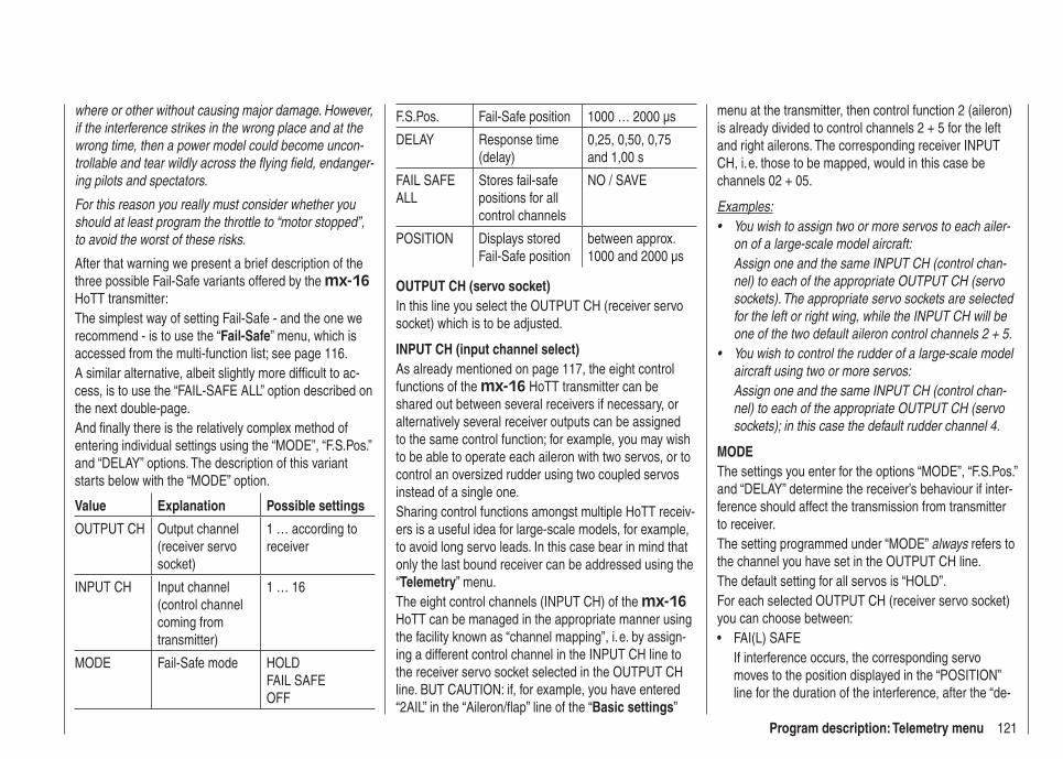
121Program description: Telemetry menu
where or other without causing major damage. However, if the interference strikes in the wrong place and at the wrong time, then a power model could become uncon-trollable and tear wildly across the fl ying fi eld, endanger-ing pilots and spectators.
For this reason you really must consider whether you should at least program the throttle to “motor stopped”, to avoid the worst of these risks.
After that warning we present a brief description of the three possible Fail-Safe variants offered by the mx-16 HoTT transmitter:The simplest way of setting Fail-Safe - and the one we recommend - is to use the “Fail-Safe” menu, which is accessed from the multi-function list; see page 116.A similar alternative, albeit slightly more diffi cult to ac-cess, is to use the “FAIL-SAFE ALL” option described on the next double-page.And fi nally there is the relatively complex method of entering individual settings using the “MODE”, “F.S.Pos.” and “DELAY” options. The description of this variant starts below with the “MODE” option.
Value Explanation Possible settings
OUTPUT CH Output channel (receiver servo socket)
1 … according to receiver
INPUT CH Input channel (control channel coming from transmitter)
1 … 16
MODE Fail-Safe mode HOLDFAIL SAFEOFF
F.S.Pos. Fail-Safe position 1000 … 2000 µs
DELAY Response time (delay)
0,25, 0,50, 0,75 and 1,00 s
FAIL SAFE ALL
Stores fail-safe positions for all control channels
NO / SAVE
POSITION Displays stored Fail-Safe position
between approx. 1000 and 2000 µs
OUTPUT CH (servo socket)In this line you select the OUTPUT CH (receiver servo socket) which is to be adjusted.
INPUT CH (input channel select)As already mentioned on page 117, the eight control functions of the mx-16 HoTT transmitter can be shared out between several receivers if necessary, or alternatively several receiver outputs can be assigned to the same control function; for example, you may wish to be able to operate each aileron with two servos, or to control an oversized rudder using two coupled servos instead of a single one.Sharing control functions amongst multiple HoTT receiv-ers is a useful idea for large-scale models, for example, to avoid long servo leads. In this case bear in mind that only the last bound receiver can be addressed using the “Telemetry” menu.The eight control channels (INPUT CH) of the mx-16 HoTT can be managed in the appropriate manner using the facility known as “channel mapping”, i. e. by assign-ing a different control channel in the INPUT CH line to the receiver servo socket selected in the OUTPUT CH line. BUT CAUTION: if, for example, you have entered “2AIL” in the “Aileron/fl ap” line of the “Basic settings”
menu at the transmitter, then control function 2 (aileron) is already divided to control channels 2 + 5 for the left and right ailerons. The corresponding receiver INPUT CH, i. e. those to be mapped, would in this case be channels 02 + 05.
Examples:You wish to assign two or more servos to each ailer-• on of a large-scale model aircraft: Assign one and the same INPUT CH (control chan-nel) to each of the appropriate OUTPUT CH (servo sockets). The appropriate servo sockets are selected for the left or right wing, while the INPUT CH will be one of the two default aileron control channels 2 + 5.You wish to control the rudder of a large-scale model • aircraft using two or more servos:Assign one and the same INPUT CH (control chan-nel) to each of the appropriate OUTPUT CH (servo sockets); in this case the default rudder channel 4.
MODEThe settings you enter for the options “MODE”, “F.S.Pos.” and “DELAY” determine the receiver’s behaviour if inter-ference should affect the transmission from transmitter to receiver.The setting programmed under “MODE” always refers to the channel you have set in the OUTPUT CH line.The default setting for all servos is “HOLD”.For each selected OUTPUT CH (receiver servo socket) you can choose between:
FAI(L) SAFE• If interference occurs, the corresponding servo moves to the position displayed in the “POSITION” line for the duration of the interference, after the “de-
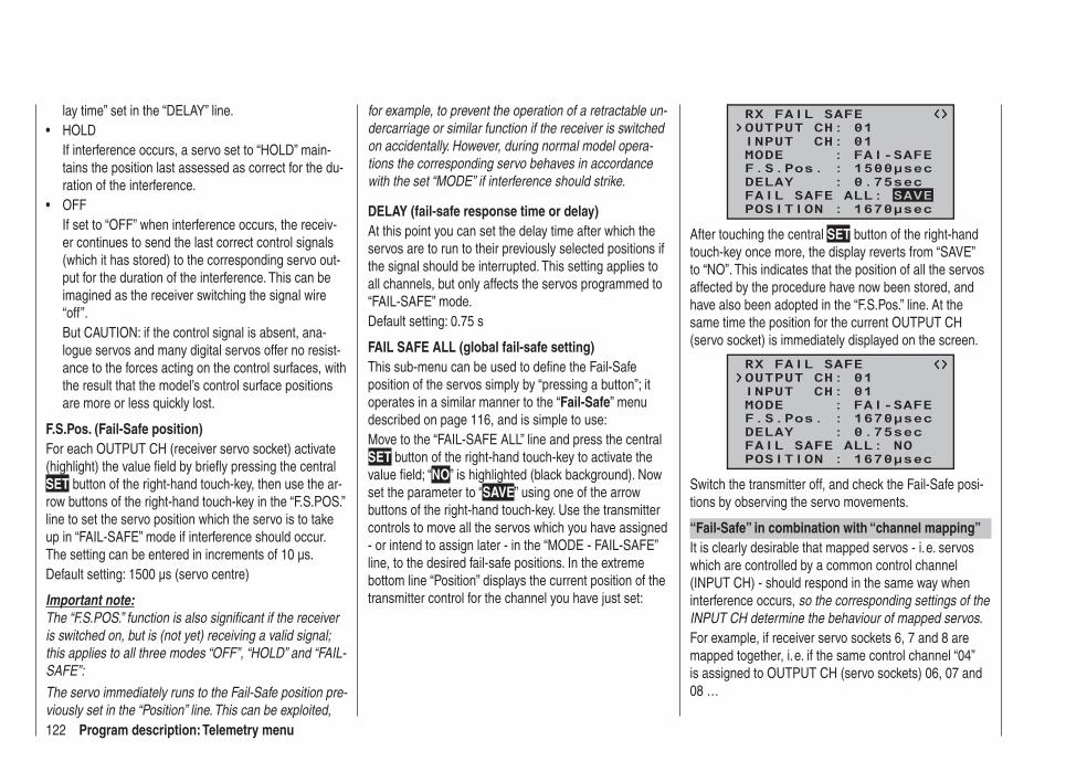
122 Program description: Telemetry menu
lay time” set in the “DELAY” line.HOLD• If interference occurs, a servo set to “HOLD” main-tains the position last assessed as correct for the du-ration of the interference.OFF• If set to “OFF” when interference occurs, the receiv-er continues to send the last correct control signals (which it has stored) to the corresponding servo out-put for the duration of the interference. This can be imagined as the receiver switching the signal wire “off”.But CAUTION: if the control signal is absent, ana-logue servos and many digital servos offer no resist-ance to the forces acting on the control surfaces, with the result that the model’s control surface positions are more or less quickly lost.
F.S.Pos. (Fail-Safe position)For each OUTPUT CH (receiver servo socket) activate (highlight) the value fi eld by briefl y pressing the central SET button of the right-hand touch-key, then use the ar-row buttons of the right-hand touch-key in the “F.S.POS.” line to set the servo position which the servo is to take up in “FAIL-SAFE” mode if interference should occur. The setting can be entered in increments of 10 µs.Default setting: 1500 µs (servo centre)
Important note:The “F.S.POS.” function is also signifi cant if the receiver is switched on, but is (not yet) receiving a valid signal; this applies to all three modes “OFF”, “HOLD” and “FAIL-SAFE”:
The servo immediately runs to the Fail-Safe position pre-viously set in the “Position” line. This can be exploited,
for example, to prevent the operation of a retractable un-dercarriage or similar function if the receiver is switched on accidentally. However, during normal model opera-tions the corresponding servo behaves in accordance with the set “MODE” if interference should strike.
DELAY (fail-safe response time or delay)At this point you can set the delay time after which the servos are to run to their previously selected positions if the signal should be interrupted. This setting applies to all channels, but only affects the servos programmed to “FAIL-SAFE” mode.Default setting: 0.75 s
FAIL SAFE ALL (global fail-safe setting)This sub-menu can be used to defi ne the Fail-Safe position of the servos simply by “pressing a button”; it operates in a similar manner to the “Fail-Safe” menu described on page 116, and is simple to use:Move to the “FAIL-SAFE ALL” line and press the central SET button of the right-hand touch-key to activate the value fi eld; “NO” is highlighted (black background). Now set the parameter to “SAVE” using one of the arrow buttons of the right-hand touch-key. Use the transmitter controls to move all the servos which you have assigned - or intend to assign later - in the “MODE - FAIL-SAFE” line, to the desired fail-safe positions. In the extreme bottom line “Position” displays the current position of the transmitter control for the channel you have just set:
RX FAIL SAFE
INPUT CH: 01MODE : FAI-SAFEF.S.Pos. : 1500μsecDELAY : 0.75sec
OUTPUT CH: 01
POSITION : 1670μsecFAIL SAFE ALL: SAVE
After touching the central SET button of the right-hand touch-key once more, the display reverts from “SAVE” to “NO”. This indicates that the position of all the servos affected by the procedure have now been stored, and have also been adopted in the “F.S.Pos.” line. At the same time the position for the current OUTPUT CH (servo socket) is immediately displayed on the screen.
RX FAIL SAFE
INPUT CH: 01MODE : FAI-SAFEF.S.Pos. : 1670μsecDELAY : 0.75sec
OUTPUT CH: 01
POSITION : 1670μsecFAIL SAFE ALL: NO
Switch the transmitter off, and check the Fail-Safe posi-tions by observing the servo movements.
“Fail-Safe” in combination with “channel mapping”It is clearly desirable that mapped servos - i. e. servos which are controlled by a common control channel (INPUT CH) - should respond in the same way when interference occurs, so the corresponding settings of the INPUT CH determine the behaviour of mapped servos.For example, if receiver servo sockets 6, 7 and 8 are mapped together, i. e. if the same control channel “04” is assigned to OUTPUT CH (servo sockets) 06, 07 and 08 …
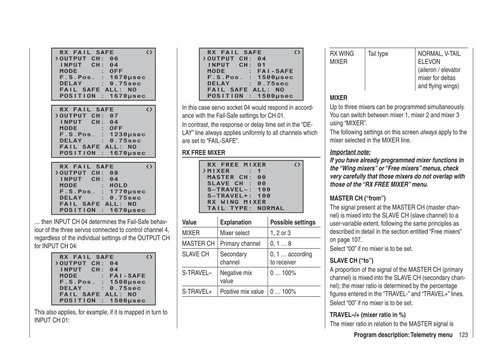
123Program description: Telemetry menu
RX FAIL SAFE
INPUT CH: 04MODE : OFFF.S.Pos. : 1670μsecDELAY : 0.75sec
OUTPUT CH: 06
POSITION : 1670μsecFAIL SAFE ALL: NO
RX FAIL SAFE
INPUT CH: 04MODE : OFFF.S.Pos. : 1230μsecDELAY : 0.75sec
OUTPUT CH: 07
POSITION : 1670μsecFAIL SAFE ALL: NO
RX FAIL SAFE
INPUT CH: 04MODE : HOLDF.S.Pos. : 1770μsecDELAY : 0.75sec
OUTPUT CH: 08
POSITION : 1670μsecFAIL SAFE ALL: NO
… then INPUT CH 04 determines the Fail-Safe behav-iour of the three servos connected to control channel 4, regardless of the individual settings of the OUTPUT CH for INPUT CH 04:
RX FAIL SAFE
INPUT CH: 04MODE : FAI-SAFEF.S.Pos. : 1500μsecDELAY : 0.75sec
OUTPUT CH: 04
POSITION : 1500μsecFAIL SAFE ALL: NO
This also applies, for example, if it is mapped in turn to INPUT CH 01:
RX FAIL SAFE
INPUT CH: 01MODE : FAI-SAFEF.S.Pos. : 1500μsecDELAY : 0.75sec
OUTPUT CH: 04
POSITION : 1500μsecFAIL SAFE ALL: NO
In this case servo socket 04 would respond in accord-ance with the Fail-Safe settings for CH 01.In contrast, the response or delay time set in the “DE-LAY” line always applies uniformly to all channels which are set to “FAIL-SAFE”.
RX FREE MIXER
RX FREE MIXER
MASTER CH: 00SLAVE CH : 00S–TRAVEL–: 100S–TRAVEL+: 100
MIXER : 1
RX WING MIXERTAIL TYPE: NORMAL
Value Explanation Possible settings
MIXER Mixer select 1, 2 or 3
MASTER CH Primary channel 0, 1 … 8
SLAVE CH Secondary channel
0, 1 … according to receiver
S-TRAVEL– Negative mix value
0 … 100%
S-TRAVEL+ Positive mix value 0 … 100%
RX WING MIXER
Tail type NORMAL, V-TAIL ELEVON (aileron / elevator mixer for deltas and fl ying wings)
MIXERUp to three mixers can be programmed simultaneously. You can switch between mixer 1, mixer 2 and mixer 3 using “MIXER”.The following settings on this screen always apply to the mixer selected in the MIXER line.
Important note:If you have already programmed mixer functions in the “Wing mixers” or “Free mixers” menus, check very carefully that those mixers do not overlap with those of the “RX FREE MIXER” menu.
MASTER CH (“from”)The signal present at the MASTER CH (master chan-nel) is mixed into the SLAVE CH (slave channel) to a user-variable extent, following the same principles as described in detail in the section entitled “Free mixers” on page 107.Select “00” if no mixer is to be set.
SLAVE CH (“to”)A proportion of the signal of the MASTER CH (primary channel) is mixed into the SLAVE CH (secondary chan-nel); the mixer ratio is determined by the percentage fi gures entered in the “TRAVEL-” and “TRAVEL+” lines.Select “00” if no mixer is to be set.
TRAVEL–/+ (mixer ratio in %)The mixer ratio in relation to the MASTER signal is
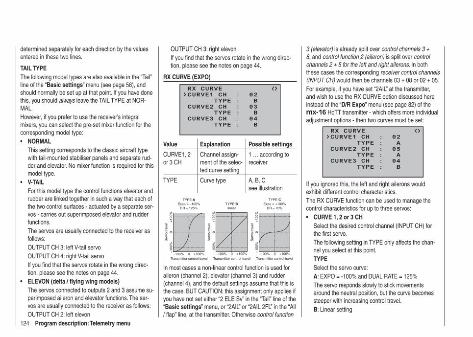
124 Program description: Telemetry menu
determined separately for each direction by the values entered in these two lines.
TAIL TYPEThe following model types are also available in the “Tail” line of the “Basic settings” menu (see page 58), and should normally be set up at that point. If you have done this, you should always leave the TAIL TYPE at NOR-MAL.However, if you prefer to use the receiver’s integral mixers, you can select the pre-set mixer function for the corresponding model type:
NORMAL• This setting corresponds to the classic aircraft type with tail-mounted stabiliser panels and separate rud-der and elevator. No mixer function is required for this model type.V-TAIL• For this model type the control functions elevator and rudder are linked together in such a way that each of the two control surfaces - actuated by a separate ser-vos - carries out superimposed elevator and rudder functions.The servos are usually connected to the receiver as follows:OUTPUT CH 3: left V-tail servoOUTPUT CH 4: right V-tail servoIf you fi nd that the servos rotate in the wrong direc-tion, please see the notes on page 44.ELEVON (delta / fl ying wing models)• The servos connected to outputs 2 and 3 assume su-perimposed aileron and elevator functions. The ser-vos are usually connected to the receiver as follows:OUTPUT CH 2: left elevon
OUTPUT CH 3: right elevonIf you fi nd that the servos rotate in the wrong direc-tion, please see the notes on page 44.
RX CURVE (EXPO)
RX CURVE
TYPE : BCURVE1 CH : 02
TYPE : BCURVE2 CH : 03
TYPE : BCURVE3 CH : 04
Value Explanation Possible settings
CURVE1, 2 or 3 CH
Channel assign-ment of the selec-ted curve setting
1 … according to receiver
TYPE Curve type A, B, Csee illustration
Ser
vo tr
avel
Transmitter control travel
Expo = +100%
–100
%+
100%
0–100% +100%0
Ser
vo tr
avel
Transmitter control travel
Expo = –100%TYPE A
–100
%+
100%
0
–100% +100%0
Ser
vo tr
avel
Transmitter control travel
linear
–100
%+
100%
0
–100% +100%0
TYPE BTYPE C
DR = 125% DR = 70%
In most cases a non-linear control function is used for aileron (channel 2), elevator (channel 3) and rudder (channel 4), and the default settings assume that this is the case. BUT CAUTION: this assignment only applies if you have not set either “2 ELE Sv” in the “Tail” line of the “Basic settings” menu, or “2AIL” or “2AIL 2FL” in the “Ail / fl ap” line, at the transmitter. Otherwise control function
3 (elevator) is already split over control channels 3 + 8, and control function 2 (aileron) is split over control channels 2 + 5 for the left and right ailerons. In both these cases the corresponding receiver control channels (INPUT CH) would then be channels 03 + 08 or 02 + 05.For example, if you have set “2AIL” at the transmitter, and wish to use the RX CURVE option discussed here instead of the “D/R Expo” menu (see page 82) of the mx-16 HoTT transmitter - which offers more individual adjustment options - then two curves must be set:
RX CURVE
TYPE : ACURVE1 CH : 02
TYPE : ACURVE2 CH : 05
TYPE : BCURVE3 CH : 04
If you ignored this, the left and right ailerons would exhibit different control characteristics.The RX CURVE function can be used to manage the control characteristics for up to three servos:
CURVE 1, 2 or 3 CH• Select the desired control channel (INPUT CH) for the fi rst servo.The following setting in TYPE only affects the chan-nel you select at this point.TYPESelect the servo curve:A: EXPO = -100% and DUAL RATE = 125% The servo responds slowly to stick movements around the neutral position, but the curve becomes steeper with increasing control travel.B: Linear setting
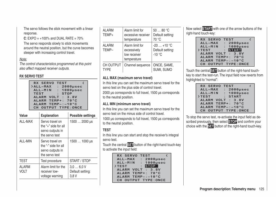
125Program description: Telemetry menu
The servo follows the stick movement with a linear response.C: EXPO = +100% and DUAL RATE = 70%The servo responds slowly to stick movements around the neutral position, but the curve becomes steeper with increasing control travel.
Note:The control characteristics programmed at this point also affect mapped receiver outputs.
RX SERVO TEST
RX SERVO TEST
ALL–MIN : 1000μsecALL–MAX : 2000μsec
ALARM VOLT : 3.8VTEST : STOP
ALARM TEMP–:–10°CALARM TEMP+: 70°C
CH OUTPUT TYPE:ONCE
Value Explanation Possible settings
ALL-MAX Servo travel on the “+” side for all servo outputs in the servo test
1500 … 2000 µs
ALL-MIN Servo travel on the “-” side for all servo outputs in the servo test
1500 … 1000 µs
TEST Test procedure START / STOP
ALARM VOLT
Alarm limit for the receiver low-voltage warning
3,0 … 6,0 VDefault setting: 3,8 V
ALARM TEMP+
Alarm limit for excessive receiver temperature
50 … 80 °CDefault setting: 70 °C
ALARM TEMP–
Alarm limit for excessively low receiver temperature
-20 … +10 °CDefault setting: -10 °C
CH OUTPUT TYPE
Channel sequence ONCE, SAME, SUMI, SUMO
ALL MAX (maximum servo travel)In this line you can set the maximum servo travel for the servo test on the plus side of control travel.2000 µs corresponds to full travel, 1500 µs corresponds to the neutral position.
ALL MIN (minimum servo travel)In this line you can set the maximum servo travel for the servo test on the minus side of control travel.1000 µs corresponds to full travel, 1500 µs corresponds to the neutral position.
TESTIn this line you can start and stop the receiver’s integral servo test.Touch the central SET button of the right-hand touch-key to activate the input fi eld:
RX SERVO TEST
ALL–MIN : 1000μsecALL–MAX : 2000μsec
ALARM VOLT : 3.8V
ALARM TEMP–:–10°CALARM TEMP+: 70°C
CH OUTPUT TYPE:ONCE
TEST : STOP
Now select START with one of the arrow buttons of the right-hand touch-key:
RX SERVO TEST
ALL–MIN : 1000μsecALL–MAX : 2000μsec
ALARM VOLT : 3.8V
ALARM TEMP–:–10°CALARM TEMP+: 70°C
CH OUTPUT TYPE:ONCE
TEST : START
Touch the central SET button of the right-hand touch-key to start the test-run. The input fi eld now reverts from highlighted to “normal”:
RX SERVO TEST
ALL–MIN : 1000μsecALL–MAX : 2000μsec
ALARM VOLT : 3.8V
ALARM TEMP–:–10°CALARM TEMP+: 70°C
CH OUTPUT TYPE:ONCE
TEST : START
To stop the servo test, re-activate the input fi eld as de-scribed previously, then select STOP and confi rm your choice with the SET button of the right-hand touch-key.

126 Program description: Telemetry menu
ALARM VOLT (low receiver voltage warning)ALARM VOLT monitors the receiver voltage. The thresh-old can be set to any value within the range 3.0 to 6.0 Volt. If the voltage falls below the set alarm limit, an audible signal (interval beeping, long / short) is trig-gered, and “VOLT.E” fl ashes at top right in all “RX …” screen displays:
RX SERVO
REVERSE : OFFCENTER : 1500μsecTRIM : –000μsecTRAVEL– : 150%
OUTPUT CH: 01
TRAVEL+ : 150%PERIOD : 20msec
VOLT.E
The parameter “R-VOLT“ is also highlighted in the “RX DATAVIEW” display:
S–STR100% R–TEM.+28°CL PACK TIME 00010msec
L.R-VOLT:03.5V
S–QUA100%S–dBM–030dBM
SENSOR1 :00.0V 00°CSENSOR2 :00.0V 00°C
R-VOLT :03.7V
RX DATAVIEW VOLT.E
ALARM TEMP +/- (receiver temperature monitor)These two options monitor the temperature of the receiver: a lower limit value “ALARM TEMP-” (-20 ... +10°C) and an upper limit value “ALARM TEMP+” (50 ... 80°C) can be programmed. If the temperature exceeds the upper limit or falls below the lower one, an audible signal (continuous beeping) is triggered, and “TEMP.E” appears at top right in all receiver displays. The param-eter “R-TEM“ is also highlighted in the “RX DATAVIEW” display.Ensure that the receiver remains within the permitted
temperature range under all fl ight conditions (ideally between -10 and +50°C).
CH OUTPUT TYPEAt this point you can select how the receiver outputs are to be addressed.
ONCE• The receiver servo sockets are addressed in se-quence; this is recommended for use with analogue servos. At this setting the servos are automatical-ly operated at a frame rate of 20 ms (30 ms with the twelve-channel receiver, Order No. 33512) - regard-less of what is set or displayed in the “PERIOD” line of the “RX SERVO” display.SAME• The receiver servo sockets are addressed in parallel blocks of four, i. e. channels 1 to 4 and channels 5 to 8 each receive their control signals simultaneously.This is recommended for use with digital servos, and especially where multiple servos are employed for a single function (e. g. ailerons), to ensure that the groups of servos run absolutely synchronously.If you are using digital servos, we recommend that you set 10 ms in the “PERIOD” line of the “RX SER-VO” display so that you can exploit the fast response of these servos. If you are using analogue servos, it is essential to select “20 ms”.If you choose the faster setting, please take par-ticular care when selecting the receiver power supply: since up to four servos can start moving si-multaneously, the load on the battery is fairly severe, so it must be a high-performance type.SUMO (Sum signal OUT)• A HoTT receiver confi gured as SUMO constant-
ly generates what is known as a sum signal from the control signals of all its control channels, and - in the case of the GR-16 receiver supplied in the set as standard - makes this available at servo socket 8.The receiver outputs are addressed in sequence at a frame rate of 20 ms (30 ms with the GR-24 receiver, Order No. 33512), even if you have set 10 ms in the “PERIOD” line of the “RX SERVO” screen page.Although primarily intended for “satellite mode” with two HoTT receivers, as described below, the sum signal generated by the receiver defi ned as SUMO can also be used, for example, to control a fl ybar-less system, or to control a fl ight simulator (using the adapter lead, Order No. 33310).In …Satellite mode… two HoTT receivers are inter-connected using a three-core connecting lead (Order No. 33700.1 (300 mm) or 33700.2 (100 mm) by the highest-numbered servo sockets. For more details on this please visit www.graupner.de on the Internet.All channels of the HoTT receiver which is confi gured as SUMO, and is defi ned as the satellite receiver, are constantly transferred to the second HoTT receiver - the primary receiver - via this connection . The prima-ry receiver must be programmed as the …SUMI (Sum signal IN). • Note that the signal only ever moves in one direction: towards the SUMI.However, if reception fails, the receiver defi ned as SUMI only uses the sum signal coming from the SUMO if at least one channel at the SUMI is pro-grammed to Fail-Safe.

127Program description: Telemetry menu
If the receiver programmed as the satellite (SUMO) suffers signal reception failure, the servos connected to that receiver take up the Fail-Safe positions pro-grammed in the satellite receiver, regardless of the primary receiver.If, in contrast, reception fails at both receivers simul-taneously, then the receiver software (the version current at the time of printing these instructions) al-ways reverts to the SUMO’s fail-safe settings. Howe-ver, mutual interactions can certainly not be ruled out in individual cases, and for this reason we ur-gently advise you to carry out appropriate tests BEFORE fl ying a model.This receiver confi guration is recommended in partic-ular circumstances: for example, if one of the two re-ceivers has to be installed in an unfavourable position in the model, or if there is a danger that the received signal will be weak in certain fl ight attitudes, per-haps due to a turbine, carbon fi bre in the airframe, or a similar problem, with the result that sporadic range problems might be expected.For this reason it is essential to connect the most im-portant control functions to the primary receiver (the one programmed as SUMI), so that interference to the satellite receiver (SUMO) does not cause the model to go out of control.Telemetry data, such as the voltage of the airborne power supply, are only sent to the transmitter by the satellite receiver (confi gured as SUMO), i. e. all te-lemetry sensors must be connected to the satellite receiver (SUMO).Each receiver should be connected to the shared power supply using its own power lead. If high cur-rents can be expected, duplicated power connections
are recommended. However, if each of the two re-ceivers is to be powered by its own battery, then it isessential to withdraw the central (red) wire from one of the two sat-ellite lead connectors, as shown in the illus-tration.
red
1
23
If you wish to carry out further programming, such as the Fail-Safe settings, disconnect the three-core satellite connection between the two receivers, and switch on just the receiver you wish to address. Note that you may also need to change the binding se-quence.
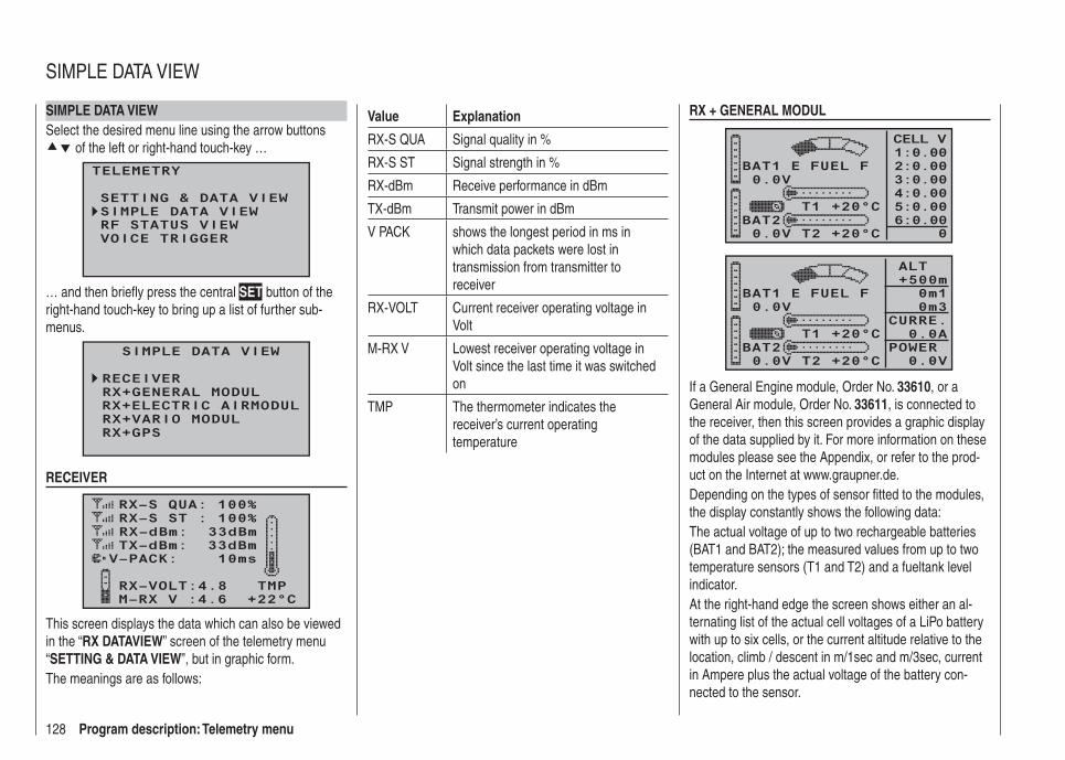
128 Program description: Telemetry menu
SIMPLE DATA VIEWSelect the desired menu line using the arrow buttons
of the left or right-hand touch-key …
TELEMETRY
SETTING & DATA VIEWSIMPLE DATA VIEWRF STATUS VIEWVOICE TRIGGER
… and then briefl y press the central SET button of the right-hand touch-key to bring up a list of further sub-menus.
SIMPLE DATA VIEW
RECEIVER
RX+ELECTRIC AIRMODULRX+GENERAL MODUL
RX+GPSRX+VARIO MODUL
RECEIVER
RX–S QUA: 100%RX–S ST : 100%
TX–dBm: 33dBmRX–dBm: 33dBm
RX–VOLT:4.8 TMP
V–PACK: 10ms
M–RX V :4.6 +22°C
This screen displays the data which can also be viewed in the “RX DATAVIEW” screen of the telemetry menu “SETTING & DATA VIEW”, but in graphic form.The meanings are as follows:
Value Explanation
RX-S QUA Signal quality in %
RX-S ST Signal strength in %
RX-dBm Receive performance in dBm
TX-dBm Transmit power in dBm
V PACK shows the longest period in ms in which data packets were lost in transmission from transmitter to receiver
RX-VOLT Current receiver operating voltage in Volt
M-RX V Lowest receiver operating voltage in Volt since the last time it was switched on
TMP The thermometer indicates the receiver’s current operating temperature
RX + GENERAL MODUL
0.0VBAT1
BAT20.0V T2 +20°C
T1 +20°C
E FUEL F
CELL V1:0.002:0.003:0.004:0.005:0.006:0.00
0
0.0VBAT1
BAT20.0V T2 +20°C
T1 +20°C
E FUEL F
ALT +500m
0m1 0m3
CURRE. 0.0APOWER
0.0V
If a General Engine module, Order No. 33610, or a General Air module, Order No. 33611, is connected to the receiver, then this screen provides a graphic display of the data supplied by it. For more information on these modules please see the Appendix, or refer to the prod-uct on the Internet at www.graupner.de.Depending on the types of sensor fi tted to the modules, the display constantly shows the following data:The actual voltage of up to two rechargeable batteries (BAT1 and BAT2); the measured values from up to two temperature sensors (T1 and T2) and a fueltank level indicator.At the right-hand edge the screen shows either an al-ternating list of the actual cell voltages of a LiPo battery with up to six cells, or the current altitude relative to the location, climb / descent in m/1sec and m/3sec, current in Ampere plus the actual voltage of the battery con-nected to the sensor.
SIMPLE DATA VIEW

129Program description: Telemetry menu
The meanings are as follows:
Value Explanation
BAT1 / BAT2 Battery 1 / Battery 2
FUEL Fuel level / Fueltank indicator
E / F Empty / full
T1 / T2 Temperature of sensor 1 / sensor 2
CELL V Cell voltage of cell 1 … max. 6
ALT Current altitude
0m1 m/1 sec climb / descent
0m3 m/3 sec climb / descent
CURRE. Actual current in Ampere
POWER Actual voltage of drive battery
RX + ELECTRIC AIRMODUL
0.0V 0m/3sBAT1 0m/1s
BAT20.0V T2 +20°C
T1 +20°C
CELL V1L0.002L0.003L0.004L0.005L0.006L0.00
0.0V 0A ALT +500m
7L0.00
0.0V 0m/3sBAT1 0m/1s
BAT20.0V T2 +20°C
T1 +20°C
CELL V1H0.002H0.003H0.004H0.005H0.006H0.00
0.0V 0A ALT +500m
7H0.00
If an Electric-Air module, Order No. 33620, is connected to the receiver, then this screen provides a graphic display of the data supplied by it. For more information
on this module please see the Appendix, or refer to the product on the Internet at www.graupner.de.Depending on the types of sensor fi tted to the module, the display constantly shows the following data:The actual voltage of up to two rechargeable batteries (BAT1 and BAT2); the measured values from up to two temperature sensors (T1 and T2); the current altitude relative to the location, and the climb / descent of the model in m/1sec and m/3sec; the centre of the screen also displays the current actually being drawn from a power source.At the right-hand edge the screen shows an alternating display of the actual cell voltages of the battery packs (max. seven cells each) connected to balancer sockets 1 (L) or 2 (H).The meanings are as follows:
Value Explanation
V Actual voltage
A Actual current
BAT1 / BAT2 Battery 1 / Battery 2
ALT Current altitude
m/1s m/1 sec climb / descent
m/3s m/3 sec climb / descent
T1 / T2 Temperature from sensor 1 / 2
CELL.V Cell voltage of cell 1 … max. 14
L Balancer socket 1
H Balancer socket 2
RX + VARIO
RXSQ 0
MAX+500m
MIN+500m
ALT+500
H
L
m/1s0
m/3s0
m/10s0
If a Vario module, Order No. 33601, is connected to the receiver, then this screen provides a graphic display of the data supplied by it. For more information on this module please see the Appendix or refer to the product on the Internet at www.graupner.de.The meanings are as follows:
Value Explanation
ALT Current altitude
RXSQ Signal strength of the signal picked up by the receiver in %
MAX The pre-set altitude limit relative to the launch point; above this altitude the transmitter emits audible warning signals
MIN The pre-set altitude limit below the launch point; below this altitude the transmitter emits audible warning signals
m/1s m/1 sec climb / descent
m/3s m/3 sec climb / descent
m/10s m/10 sec climb / descent

130 Program description: Telemetry menu
RX + GPS
NRXSQ 0 DIS 0mALT +500m
0m/1s 0m/3s 0m/10s
N 0°00.0000E 0°00.0000
W E
S
Kmh0
If a GPS module with integral vario, Order No. 33600, is connected to the receiver, then this screen provides a graphic display of the data supplied by it. For more information on this module please see the Appendix, or refer to the product on the Internet at www.graupner.de.The centre of the screen shows the current positional data and the model’s speed; the display also shows the model’s current altitude in relation to the launch point, its climb / descent rate at m/1 sec, m/3 sec and m/10 sec, the current reception quality and the model’s range from the launch point.The meanings are as follows:
Value Explanation
W / N / E / S West / North / East / South
Kmh Speed
RXSQ Signal strength of downlink channel
DIS Distance
ALT Current altitude relative to launch point
m/1s m/1 sec climb / descent
m/3s m/3 sec climb / descent
m/10s m/10 sec climb / descent
RF STATUS VIEWSelect the desired menu line with the arrow buttons
of the left or right-hand touch-key …
TELEMETRY
SETTING & DATA VIEWSIMPLE DATA VIEWRF STATUS VIEWVOICE TRIGGER
… and then press the central SET button of the right-hand touch-key to open the selected sub-menu:
R100%
TD 22
E 10RD 414.8VC
S 95%
4.8VM 0123456789ABCDE
Top row: receive performance in dBm of channels 1 ... 75 on the 2.4 GHz band.
Bottom row: receive performance in dBm of the sig-nal of channels 1 ... 75 on the 2.4 GHz band, as picked up by the receiver.
This screen provides a graphic display of data showing the occupation of the 2.4 GHz band.As well as the graphic depiction of band occupation, additional numeric information is generated to the left of the graphs. The meanings are as follows:
Value Explanation
R Signal quality in % for the signal arriving from the receiver
S Signal quality in % for the signal arriving at the receiver
TD Reception performance in dBm
E Number of lost receiver data packets
RD Reception performance in dBm of the signal picked up by the receiver
VC Actual receiver operating voltage in Volt
VM Lowest receiver operating voltage in Volt since the last time it was switched on
RF STATUS VIEW
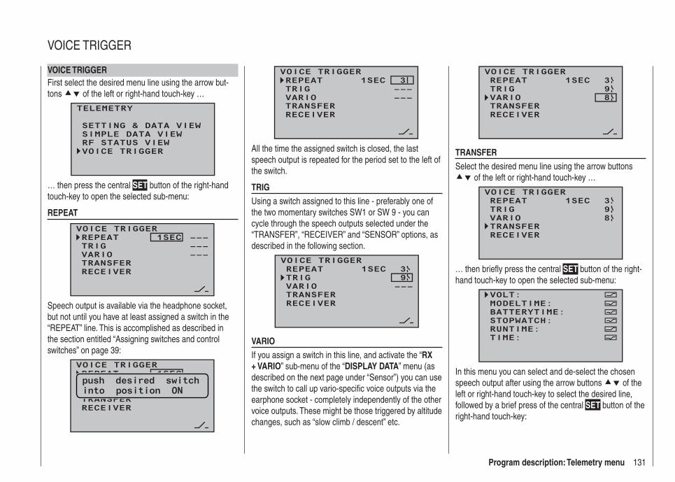
131Program description: Telemetry menu
VOICE TRIGGERFirst select the desired menu line using the arrow but-tons of the left or right-hand touch-key …
TELEMETRY
SETTING & DATA VIEWSIMPLE DATA VIEWRF STATUS VIEWVOICE TRIGGER
… then press the central SET button of the right-hand touch-key to open the selected sub-menu:
REPEAT
VOICE TRIGGERREPEAT 1SECTRIG
TRANSFERRECEIVER
––––––
VARIO –––
Speech output is available via the headphone socket, but not until you have at least assigned a switch in the “REPEAT” line. This is accomplished as described in the section entitled “Assigning switches and control switches” on page 39:
VOICE TRIGGERREPEAT 1SEC
TRANSFERRECEIVER
push desired switchinto position ON
VOICE TRIGGERREPEAT 1SECTRIG
TRANSFERRECEIVER
–––3
VARIO –––
All the time the assigned switch is closed, the last speech output is repeated for the period set to the left of the switch.
TRIGUsing a switch assigned to this line - preferably one of the two momentary switches SW1 or SW 9 - you can cycle through the speech outputs selected under the “TRANSFER”, “RECEIVER” and “SENSOR” options, as described in the following section.
VOICE TRIGGER
TRIG
TRANSFERRECEIVER
93REPEAT 1SEC
VARIO –––
VARIOIf you assign a switch in this line, and activate the “RX + VARIO” sub-menu of the “DISPLAY DATA” menu (as described on the next page under “Sensor”) you can use the switch to call up vario-specifi c voice outputs via the earphone socket - completely independently of the other voice outputs. These might be those triggered by altitude changes, such as “slow climb / descent” etc.
VOICE TRIGGER
TRIG
TRANSFERRECEIVER
93REPEAT 1SEC
VARIO 8
TRANSFERSelect the desired menu line using the arrow buttons
of the left or right-hand touch-key …
VOICE TRIGGERREPEAT 1SECTRIG
TRANSFERRECEIVER
39
VARIO 8
… then briefl y press the central SET button of the right-hand touch-key to open the selected sub-menu:
VOLT:MODELTIME:BATTERYTIME:
RUNTIME:STOPWATCH:
TIME:
In this menu you can select and de-select the chosen speech output after using the arrow buttons of the left or right-hand touch-key to select the desired line, followed by a brief press of the central SET button of the right-hand touch-key:
VOICE TRIGGER
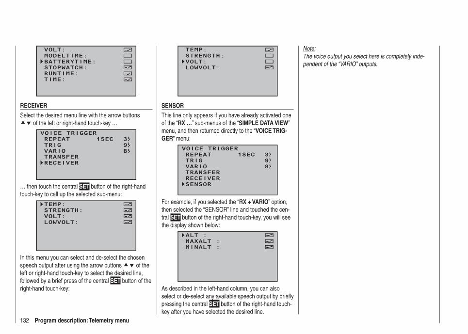
132 Program description: Telemetry menu
VOLT:MODELTIME:BATTERYTIME:
RUNTIME:STOPWATCH:
TIME:
RECEIVERSelect the desired menu line with the arrow buttons
of the left or right-hand touch-key …
VOICE TRIGGERREPEAT 1SECTRIG
TRANSFERRECEIVER
39
VARIO 8
… then touch the central SET button of the right-hand touch-key to call up the selected sub-menu:
TEMP:STRENGTH:VOLT:LOWVOLT:
In this menu you can select and de-select the chosen speech output after using the arrow buttons of the left or right-hand touch-key to select the desired line, followed by a brief press of the central SET button of the right-hand touch-key:
TEMP:STRENGTH:VOLT:LOWVOLT:
SENSORThis line only appears if you have already activated one of the “RX …” sub-menus of the “SIMPLE DATA VIEW” menu, and then returned directly to the “VOICE TRIG-GER” menu:
VOICE TRIGGERREPEAT 1SECTRIG
TRANSFERRECEIVER
39
SENSOR
VARIO 8
For example, if you selected the “RX + VARIO” option, then selected the “SENSOR” line and touched the cen-tral SET button of the right-hand touch-key, you will see the display shown below:
ALT :MAXALT :MINALT :
As described in the left-hand column, you can also select or de-select any available speech output by briefl y pressing the central SET button of the right-hand touch-key after you have selected the desired line.
Note:The voice output you select here is completely inde-pendent of the “VARIO” outputs.

133For your notes

134 Program description: Trainer system
Trainer ModeConnecting two transmitters for trainer mode operations using a Trainer lead
Use the arrow buttons of the left or right-hand touch-key to leaf through to the “Trainer” menu point of the multi-function menu:
servo set.D/R expowing mixer
contr set.phase tr imfree mixer
servo disp basic settfail-safe telemetry
info dispteach/pupi
servo set.D/R expofree mixer
contr set.heli mixerswashp.mix
servo disp basic settfail-safe telemetryteach/pupi info disp
Touch the central SET button of the right-hand touch-key to open the menu:
TRAINER/Pupil
–PT
2 3 4 5 6 7 8BIND:SW: –––
1N/A
The illustration above shows the initial state of this menu: transmitter controls have not been released ( ) to the pupil, and a switch has not been assigned (SW: --- at bottom right and -P on the left of the display).
Teacher transmitter settingsUp to eight transmitter control functions of the Teacher transmitter “T” can be transferred individually or in any combination to the pupil transmitter “P”.The lower line of the display marked “T” therefore indicates those transmitter controls which are perma-nently connected to the inputs 1 … 4 (dual-axis stick functions, fi xed-wing model and model helicopter), plus the transmitter controls CTRL 6 to 8, which can be assigned to inputs 5 … 8 in the “Transmitter control settings” menu.
Notes:This means that the three-position switches SW 4/5 • and 6/7, designated CTRL 9 and 10, explicitly CAN-NOT be transferred.Transmitter controls can only be assigned in the • “Transmitter control settings” menu when the Train-er connection is switched off.
Use the arrow buttons of the left or right-hand touch-key to select the transmitter controls 1 to 8 ( ) to be transferred to the pupil, and briefl y press the central SET button of the right-hand touch-key in each case, so that they switch from “T (Teacher)” ( ) to “P (Pupil)” ( ):
–PT
1 2 3 4 6 7 85BIND:SW: ––– N/A
TRAINER/Pupil
You still have to assign a Trainer transfer switch on the right of the screen so that you can actually transfer con-trol to the Pupil. This is accomplished by using the arrow
buttons of the left or right-hand touch-key to place the marker next to “SW” at bottom right, and assign a switch as described on page 39.We recommend that you use one of the two momentary switches SW 1 or SW 9 as the transfer switch, to ensure that the Teacher transmitter can regain control instantly at any time.
T1 2 3 4 5 6 7 8
P
BIND:SW: N/A9
TRAINER/Teach
Note:The switch assignment procedure described above determines which transmitter provides the Teacher function, and which provides the Pupil function. For this reason a switch must NEVER be assigned to the Pupil transmitter in this menu. To underline this, the menu headline switches from “TRAINER / pupil” to “TRAI-NER / teacher” as soon as a switch is assigned.
The model to be controlled by the pupil must be pro-grammed completely in a model memory of the mx-16 HoTT Teacher transmitter, i. e. with all its functions including trims and any mixer functions. The HoTT re-ceiver in the model must also be “bound” to the Teacher transmitter, since it is this transmitter which actually controls the model in Pupil mode, even in Trainer opera-tions.The mx-16 HoTT Teacher transmitter MUST ALWAYS BE SWITCHED ON FIRST. ONLY THEN MAY THE CONNECTING LEAD BE PLUGGED INTO IT. If you
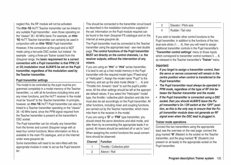
135Program description: Trainer system
neglect this, the RF module will not be activated.The mx-16 HoTT Teacher transmitter can be linked to any suitable Pupil transmitter - even those operating on the “classic” 35 / 40 MHz band. For example, an mx-16 HoTT Teacher transmitter can certainly be used in conjunction with an mx-16(s) Pupil transmitter.However, if the connection at the pupil end is NOT made using a two-pole DSC socket, but instead - for example - using a three-pin Trainer socket from the Graupner range, the basic requirement for a correct connection with a Pupil transmitter is that PPM (18 or 24) modulation must ALWAYS be set on the Pupil transmitter, regardless of the modulation used by the Teacher transmitter.
Pupil transmitter settingsThe model to be controlled by the pupil must be pro-grammed completely in a model memory of the Teacher transmitter, i. e. with all its functions including trims and any mixer functions, and the HoTT receiver in the model must be “bound” to the Teacher transmitter. In principle, however, an mx-16 HoTT Pupil transmitter can also be linked to a Teacher transmitter operating on the “classic” 35 / 40 MHz band, since the PPM signal required from the Teacher transmitter is present at the transmitter’s DSC socket.The Pupil transmitter can be virtually any transmitter from the former and current Graupner range with at least four control functions. More information on this is available in the main FS catalogue, and on the Internet under www.graupner.de.Some transmitters will need to be retro-fi tted with the appropriate module in order to act as the Pupil transmit-ter.
This should be connected to the transmitter circuit board as described in the installation instructions supplied in the set. Information on the Pupil module required can be found in the main Graupner FS catalogue and on the Internet at www.graupner.de.The Pupil transmitter must be connected to the Teacher transmitter using the appropriate lead - see next double page. The control functions of the Pupil transmitter MUST act directly on the control channels, i. e. the receiver outputs, without the intervention of any mixers.If you are using an “mc” or “mx” series transmitter, it is best to set up a free model memory in the Pupil transmitter with the required model type (“Fixed-wing” or “Helicopter”). Assign the model name “Pupil” to the memory, and set up the stick mode (Mode 1 … 4) and “Throttle min. forward / back” to suit the pupil’s prefer-ence. All the other settings should be left at the appropri-ate default values. If you select the “Helicopter” model type, the throttle / collective pitch direction and idle trim must also be set accordingly on the Pupil transmitter. All other functions, including mixer and coupling functions, are carried out by the Teacher transmitter, which trans-mits them to the receiver in the model.If you are using a “D” or “FM” type transmitter, you should check the servo directions and stick mode, and alter them by re-connecting the appropriate leads if re-quired. All mixers should be switched off or set to “zero”.When assigning the control functions the usual conven-tions should be observed:
Channel Function
1 Throttle / Collective pitch
2 Aileron / Roll
3 Elevator / Pitch-axis
4 Rudder / Tail rotor
If you wish to transfer other control functions to the Pupil transmitter, in addition to the functions of the two dual-axis sticks (1 … 4), then you will need to assign additional transmitter controls in the Pupil transmitter’s “Transmitter control settings” menu to those inputs which correspond to transmitter control numbers 5 … 8, as released in the Teacher transmitter’s “Trainer” menu.
Important:If you forget to assign a transmitter control, then • the servo or servos concerned will remain in the centre position when control is transferred to the Pupil transmitter.The Pupil transmitter must always be operated in • PPM mode, regardless of the type of RF link be-tween the Teacher transmitter and the model.If the Pupil transmitter is connected using a DSC • socket, then you should ALWAYS leave the Pu-pil transmitter’s On / Off switch at the “OFF” posi-tion, as this is the only way to ensure that the Pu-pil transmitter module does not generate an RF signal even when the DSC lead is plugged in.
Trainer mode operationsConnect the two transmitters using the appropriate lead; see the overview on the next page: connect the plug marked “M” (Master) to the socket on the Teacher transmitter, and the plug marked “S” (Student) (not present on all leads) to the appropriate socket on the Pupil transmitter.
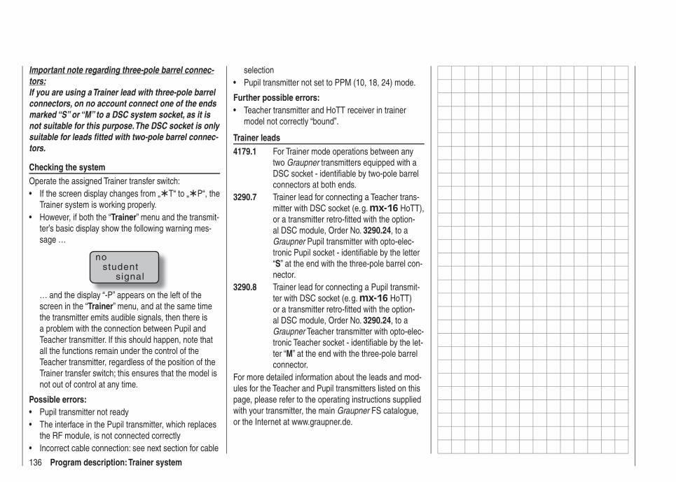
136 Program description: Trainer system
Important note regarding three-pole barrel connec-tors:If you are using a Trainer lead with three-pole barrel connectors, on no account connect one of the ends marked “S” or “M” to a DSC system socket, as it is not suitable for this purpose. The DSC socket is only suitable for leads fi tted with two-pole barrel connec-tors.
Checking the systemOperate the assigned Trainer transfer switch:
If the screen display changes from „• T“ to „ P“, the Trainer system is working properly.However, if both the “• Trainer” menu and the transmit-ter’s basic display show the following warning mes-sage …
nostudent
signal
… and the display “-P” appears on the left of the screen in the “Trainer” menu, and at the same time the transmitter emits audible signals, then there is a problem with the connection between Pupil and Teacher transmitter. If this should happen, note that all the functions remain under the control of the Teacher transmitter, regardless of the position of the Trainer transfer switch; this ensures that the model is not out of control at any time.
Possible errors:Pupil transmitter not ready• The interface in the Pupil transmitter, which replaces • the RF module, is not connected correctlyIncorrect cable connection: see next section for cable •
selectionPupil transmitter not set to PPM (10, 18, 24) mode.•
Further possible errors:Teacher transmitter and HoTT receiver in trainer • model not correctly “bound”.
Trainer leads4179.1 For Trainer mode operations between any
two Graupner transmitters equipped with a DSC socket - identifi able by two-pole barrel connectors at both ends.
3290.7 Trainer lead for connecting a Teacher trans-mitter with DSC socket (e. g. mx-16 HoTT), or a transmitter retro-fi tted with the option-al DSC module, Order No. 3290.24, to a Graupner Pupil transmitter with opto-elec-tronic Pupil socket - identifi able by the letter “S” at the end with the three-pole barrel con-nector.
3290.8 Trainer lead for connecting a Pupil transmit-ter with DSC socket (e. g. mx-16 HoTT) or a transmitter retro-fi tted with the option-al DSC module, Order No. 3290.24, to a Graupner Teacher transmitter with opto-elec-tronic Teacher socket - identifi able by the let-ter “M” at the end with the three-pole barrel connector.
For more detailed information about the leads and mod-ules for the Teacher and Pupil transmitters listed on this page, please refer to the operating instructions supplied with your transmitter, the main Graupner FS catalogue, or the Internet at www.graupner.de.
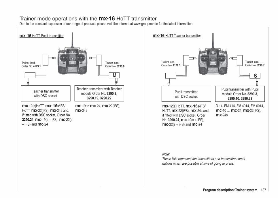
137Program description: Trainer system
Trainer mode operations with the mx-16 HoTT transmitterDue to the constant expansion of our range of products please visit the Internet at www.graupner.de for the latest information.
Teacher transmitter with DSC socket
Teacher transmitter with Teacher module Order No. 3290.2,
3290.19, 3290.22
Trainer lead, Order No. 4179.1
Trainer lead, Order No. 3290.8
M
mx-16 HoTT Pupil transmitter
mx-12(s)HoTT, mx-16s/iFS/HoTT, mx-22(iFS), mx-24s and, if fi tted with DSC socket, Order No. 3290.24, mc-19(s + iFS), mc-22(s + iFS) and mc-24
mc-19 to mc-24, mx-22(iFS), mx-24s
mitter
Pupil transmitterwith DSC socket
Pupil transmitter with Pupil module Order No. 3290.3,
3290.10, 3290.33
Trainer lead, Order No. 4179.1
Trainer lead, Order No. 3290.7
D 14, FM 414, FM 4014, FM 6014, mc-10 … mc-24, mx-22(iFS), mx-24s
S
mx-16 HoTT Teacher transmitter
mx-12(s)HoTT, mx-16s/iFS/HoTT, mx-22(iFS), mx-24s and, if fi tted with DSC socket, Order No. 3290.24, mc-19(s + iFS), mc-22(s + iFS) and mc-24
ter
Note:These lists represent the transmitters and transmitter combi-nations which are possible at time of going to press.

138 Program description: Trainer system
Wireless HoTT system
Two HoTT transmitters can also be combined by wire-less means to form a Trainer system as an alternative to the “classic” system using a Trainer lead, as described on the preceding pages.
PreparationsThe trainer model must be programmed completely, i. e. with all its functions including trims and any mixer functions, both in a model memory of the mx-16 HoTT Pupil transmitter and also in the mx-16 HoTT Teacher transmitter. This means that it must be possible to control the trainer model fully, without restriction, by both transmitters, i. e. by the Teacher and the Pupil transmitters. It is very important to avoid any major set-up differences, otherwise there is a risk that the servos will jump abruptly from one position to another when control is transferred between the Teacher and Pupil transmitters, which can place a severe strain on the servos. Nevertheless, it may be sensible to program smaller control surface travels on the Pupil model at least, as this makes it easier to learn the basic skills of model fl ying. Once both transmitters are prepared for training opera-tions as described above, the trainer model should be bound to the Pupil transmitter. A detailed description of the binding procedure can be found on pages 61 and 70.
Binding the Teacher and Pupil transmittersSwitch both transmitters on, and use the arrow buttons of the left or right-hand touch-key to leaf through on both transmitters to the “Trainer” menu point of the multi-function menu. (The trainer model’s receiving system, previously bound to the Pupil transmitter, does not need to be switched on during the following procedure.)
servo set.D/R expowing mixer
contr set.phase tr imfree mixer
servo disp basic settfail-safe telemetry
info dispteach/pupi
servo set.D/R expofree mixer
contr set.heli mixerswashp.mix
servo disp basic settfail-safe telemetryteach/pupi info disp
Touch the central SET button of the right-hand touch-key to open the following menu point:
TRAINER/Pupil
–PT
2 3 4 5 6 7 8BIND:SW: –––
1N/A
The illustration above shows the initial state of this menu: no transmitter controls have been released to the Pupil ( ), and no switches have been assigned (SW: --- bottom right and -S on left of illustration).
Pupil transmitterUse the arrow buttons of the left or right-hand touch-key to move the marker / cursor to the input fi eld marked “Bind”. If a switch is displayed adjacent to “SW” on the right, then it is essential to erase this: see the following illustration:
–PT
2 3 4 5 6 7 8BIND: N/ASW: –––
1
TRAINER/Pupil
Teacher transmitterTouch the central SET button of the right-hand touch-key to release the control channels to be transferred to the Pupil. When you do this, the corresponding symbol changes from to . For example:
–PT
1 2 3 4 6 7 85BIND:SW: ––– N/A
TRAINER/Pupil
Important Note:In contrast to the wired Trainer system described in the previous section, in which TRANSMITTER CONTROL SIGNALS are released to the Pupil exclusively, it is CONTROL CHANNELS which are transferred when using the wireless HoTT system which is described in this section.
For example, if the aileron function (2) is to be trans-ferred, and if the model is equipped with two aileron servos which are usually connected to receiver sockets 2 and 5, then in the wireless system control channels 2 and 5 must also be transferred, and not just - as with the wired system - number 2; see illustration above. The same applies to fl ap servos connected to 6 and 7 (“2AIL
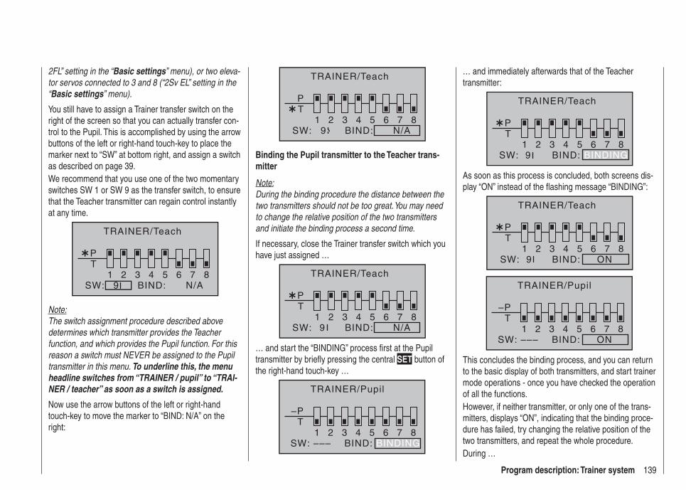
139Program description: Trainer system
2FL” setting in the “Basic settings” menu), or two eleva-tor servos connected to 3 and 8 (“2Sv EL” setting in the “Basic settings” menu).
You still have to assign a Trainer transfer switch on the right of the screen so that you can actually transfer con-trol to the Pupil. This is accomplished by using the arrow buttons of the left or right-hand touch-key to place the marker next to “SW” at bottom right, and assign a switch as described on page 39.We recommend that you use one of the two momentary switches SW 1 or SW 9 as the transfer switch, to ensure that the Teacher transmitter can regain control instantly at any time.
T1 2 3 4 5 6 7 8
P
BIND:SW: N/A9
TRAINER/Teach
Note:The switch assignment procedure described above determines which transmitter provides the Teacher function, and which provides the Pupil function. For this reason a switch must NEVER be assigned to the Pupil transmitter in this menu. To underline this, the menu headline switches from “TRAINER / pupil” to “TRAI-NER / teacher” as soon as a switch is assigned.
Now use the arrow buttons of the left or right-hand touch-key to move the marker to “BIND: N/A” on the right:
T1 2 3 4 5 6 7 8
P
BIND:SW: N/A9
TRAINER/Teach
Binding the Pupil transmitter to the Teacher trans-mitter
Note:During the binding procedure the distance between the two transmitters should not be too great. You may need to change the relative position of the two transmitters and initiate the binding process a second time.
If necessary, close the Trainer transfer switch which you have just assigned …
T1 2 3 4 5 6 7 8
P
BIND:SW: N/A9
TRAINER/Teach
… and start the “BINDING” process fi rst at the Pupil transmitter by briefl y pressing the central SET button of the right-hand touch-key …
–PT
2 3 4 5 6 7 8BIND:SW: –––
1BINDING
TRAINER/Pupil
… and immediately afterwards that of the Teacher transmitter:
T1 2 3 4 5 6 7 8
BIND:SW: 9
P
BINDING
TRAINER/Teach
As soon as this process is concluded, both screens dis-play “ON” instead of the fl ashing message “BINDING”:
T1 2 3 4 5 6 7 8
BIND: ONSW: 9
P
TRAINER/Teach
–PT
2 3 4 5 6 7 8BIND: ONSW: –––
1
TRAINER/Pupil
This concludes the binding process, and you can return to the basic display of both transmitters, and start trainer mode operations - once you have checked the operation of all the functions.However, if neither transmitter, or only one of the trans-mitters, displays “ON”, indicating that the binding proce-dure has failed, try changing the relative position of the two transmitters, and repeat the whole procedure.During …

140 Program description: Trainer system
Trainer mode operations… it is no problem for the Teacher and Pupil to stand a little way apart. However, you should never exceed a distance of 50 m (this is known as the call range), and no other persons should stand between the Teacher and Pupil, as this could reduce the effective range. Please note also that the wireless Trainer function exploits the downlink connection, and for this reason no telemetry data are transmitted from the model in this mode.In this mode of operation the basic display of the Teach-er transmitter looks like this …
GRAUBELE#01
2:22h
stop flt«normal »
0:000:00
5.5V51%5.2V HoTT
P
RFC–Teach
… and that of the Pupil transmitter typically like this:
GRAUBELE#09
1:11h
stop flt
0:000:00
33%4.9V HoTTRFC-Pupil
If it should occur that the link between the Teacher and Pupil transmitters is lost during Trainer mode operations, note that the Teacher transmitter automatically assumes control of the model.In this situation, if the Trainer change-over switch is in the “Pupil” position, then the central LED on the Teacher transmitter starts to fl ash blue / red for the duration of the signal loss, and the transmitter emits audible warn-
ing signals. At the same time “RFC-” fl ashes in the basic display, and the following warning is displayed:
nostudent
signal
However, if only “RFC-” fl ashes in the basic transmitter display, and - relatively quiet - audible signals are heard …
GRAUBELE#01
2:22h
stop flt«normal »
0:000:00
5.5V51%5.2V HoTT
P
RFC–Teach
… then this indicates that the Pupil signal has also been lost, but the Trainer transfer switch is in the “Teacher” position. In either situation your fi rst recourse should be to reduce the distance between the two transmitters. If this does not help, land the model immediately, and seek the cause.However, if both transmitters are operating with the re-ceiving system switched off, then the “familiar” symbol appears in the basic display of the Teacher transmitter instead of the two symbols.
Resuming Trainer mode operationsIf - for whatever reason - one or both transmitters are switched off during a Trainer mode session, then the screen displays the following query when the transmitter or transmitters are switched on again:
TRAINERWireless Link
INHACT
Touch the central SET button of the right-hand touch-key to confi rm “ACT(ivate)”, or alternatively wait for about two seconds until the message disappears; the last link you created with a Teacher or Pupil transmitter is now restored.However, if you select “INH(ibit)” using one of the arrow buttons of the left or right-hand touch-key …
TRAINERWireless Link
INHACT
… and confi rm your choice by briefl y pressing the cen-tral SET button of the right-hand touch-key, this resets that transmitter to “normal” operation. In this case you will have to repeat the binding process with a Teacher or Pupil transmitter as and when required.

141For your notes
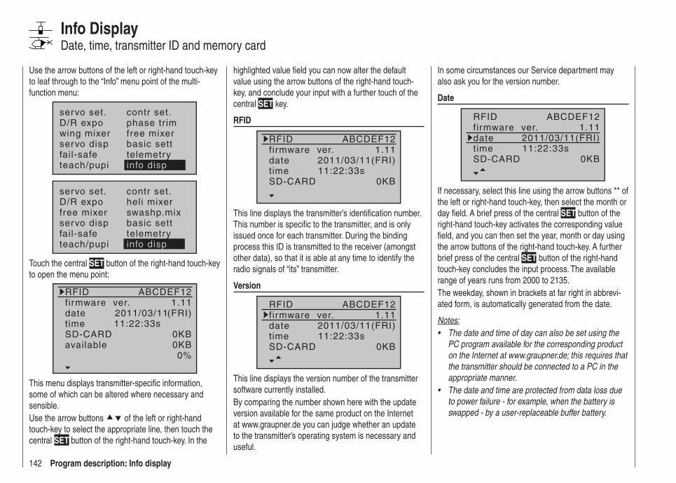
142 Program description: Info display
Info DisplayDate, time, transmitter ID and memory card
Use the arrow buttons of the left or right-hand touch-key to leaf through to the “Info” menu point of the multi-function menu:
servo set.D/R expowing mixer
contr set.phase tr imfree mixer
servo disp basic settfail-safe telemetryteach/pupi info disp
servo set.D/R expofree mixer
contr set.heli mixerswashp.mix
servo disp basic settfail-safe telemetryteach/pupi info disp
Touch the central SET button of the right-hand touch-key to open the menu point:
RFIDfirmware ver.datetimeSD-CARDavailable
(FRI)1.11
0KB0%
ABCDEF12
2011/03/1111:22:33s
0KB
This menu displays transmitter-specifi c information, some of which can be altered where necessary and sensible.Use the arrow buttons of the left or right-hand touch-key to select the appropriate line, then touch the central SET button of the right-hand touch-key. In the
highlighted value fi eld you can now alter the default value using the arrow buttons of the right-hand touch-key, and conclude your input with a further touch of the central SET key.
RFID
RFIDfirmware ver.datetimeSD-CARD
(FRI)1.11
0KB
ABCDEF12
2011/03/1111:22:33s
This line displays the transmitter’s identifi cation number. This number is specifi c to the transmitter, and is only issued once for each transmitter. During the binding process this ID is transmitted to the receiver (amongst other data), so that it is able at any time to identify the radio signals of “its” transmitter.
Version
RFIDfirmware ver.datetimeSD-CARD
(FRI)1.11
0KB
ABCDEF12
2011/03/1111:22:33s
This line displays the version number of the transmitter software currently installed.By comparing the number shown here with the update version available for the same product on the Internet at www.graupner.de you can judge whether an update to the transmitter’s operating system is necessary and useful.
In some circumstances our Service department may also ask you for the version number.
Date
RFIDfirmware ver.datetimeSD-CARD
(FRI)1.11
0KB
ABCDEF12
2011/03/1111:22:33s
If necessary, select this line using the arrow buttons ** of the left or right-hand touch-key, then select the month or day fi eld. A brief press of the central SET button of the right-hand touch-key activates the corresponding value fi eld, and you can then set the year, month or day using the arrow buttons of the right-hand touch-key. A further brief press of the central SET button of the right-hand touch-key concludes the input process. The available range of years runs from 2000 to 2135.The weekday, shown in brackets at far right in abbrevi-ated form, is automatically generated from the date.
Notes:The date and time of day can also be set using the • PC program available for the corresponding product on the Internet at www.graupner.de; this requires that the transmitter should be connected to a PC in the appropriate manner.The date and time are protected from data loss due • to power failure - for example, when the battery is swapped - by a user-replaceable buffer battery.

143Program description: Info display
Time
RFIDfirmware ver.datetimeSD-CARD
(FRI)1.11
0KB
ABCDEF12
2011/03/1111:22:33s
If necessary, you can select this line, and the minutes fi eld, using the arrow buttons of the left or right-hand touch-key. A brief press on the central SET button of the right-hand touch-key activates the corresponding value fi eld, and you can then adjust the hours or minutes using the arrow buttons of the right-hand touch-key. A further brief press on the central SET button of the right-hand touch-key concludes the entry process.Note that the seconds display cannot be set directly; instead it can be reset to “00” with a touch of the central SET button of the right-hand touch-key.
Notes:The date and time of day can also be set using the • PC program available for the corresponding product on the Internet at www.graupner.de; this requires that the transmitter should be connected to a PC in the appropriate manner.The date and time are protected from data loss due • to power failure - for example, when the battery is swapped - by a user-replaceable buffer battery.
SD card
RFIDfirmware ver.datetimeSD-CARD
(FRI)1.11
2048KB
ABCDEF12
2011/03/1111:22:33s
This line displays the storage capacity in KB of a memo-ry card installed in the transmitter.Depending on the memory capacity of the micro-SD or micro-SDHC memory card fi tted in the transmitter, it may take several minutes for the display to show the correct value after you switch the transmitter on.
available
firmware ver.datetimeSD-CARD
(FRI)1.11
2048KB
2011/03/1111:22:33s
available 1234KB
Display of the available memory in KB.As already mentioned, it may take a certain amount of time for the available memory to be displayed after you switch the transmitter on, depending on the total capac-ity of the installed memory card.The next line down displays the available memory in relation to the total memory capacity:
datetimeSD-CARD
(FRI)2048KB
2011/03/1111:22:33s
available 1234KB60%
As already mentioned, it may take a certain amount of time for the available memory to be displayed after you switch the transmitter on, depending on the total capac-ity of the installed memory card.
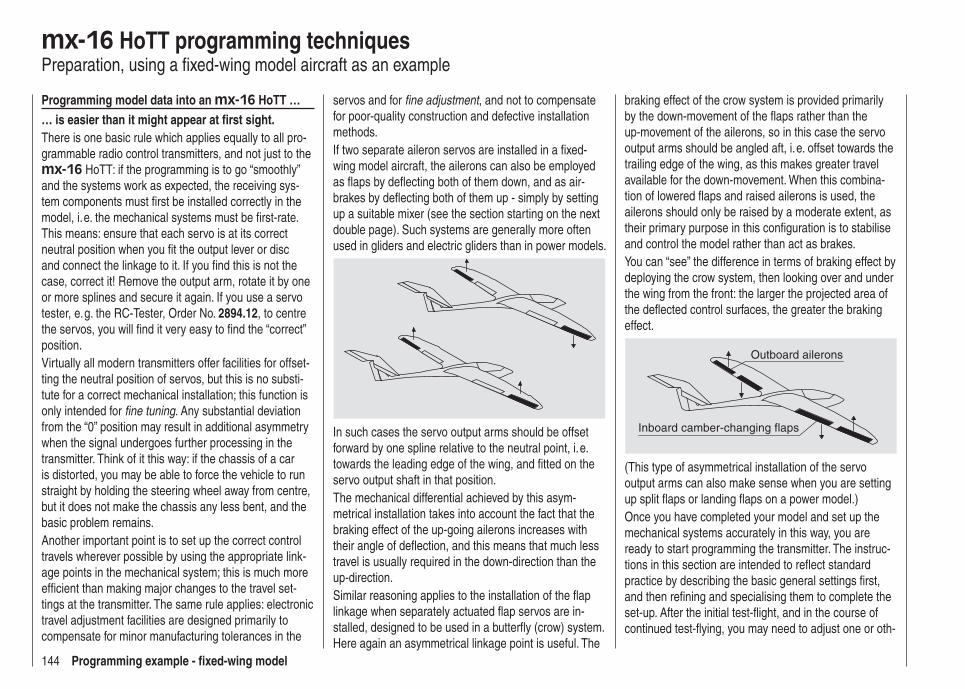
144 Programming example - fi xed-wing model
mx-16 HoTT programming techniquesPreparation, using a fi xed-wing model aircraft as an example
Programming model data into an mx-16 HoTT …… is easier than it might appear at fi rst sight.There is one basic rule which applies equally to all pro-grammable radio control transmitters, and not just to the mx-16 HoTT: if the programming is to go “smoothly” and the systems work as expected, the receiving sys-tem components must fi rst be installed correctly in the model, i. e. the mechanical systems must be fi rst-rate. This means: ensure that each servo is at its correct neutral position when you fi t the output lever or disc and connect the linkage to it. If you fi nd this is not the case, correct it! Remove the output arm, rotate it by one or more splines and secure it again. If you use a servo tester, e. g. the RC-Tester, Order No. 2894.12, to centre the servos, you will fi nd it very easy to fi nd the “correct” position.Virtually all modern transmitters offer facilities for offset-ting the neutral position of servos, but this is no substi-tute for a correct mechanical installation; this function is only intended for fi ne tuning. Any substantial deviation from the “0” position may result in additional asymmetry when the signal undergoes further processing in the transmitter. Think of it this way: if the chassis of a car is distorted, you may be able to force the vehicle to run straight by holding the steering wheel away from centre, but it does not make the chassis any less bent, and the basic problem remains.Another important point is to set up the correct control travels wherever possible by using the appropriate link-age points in the mechanical system; this is much more effi cient than making major changes to the travel set-tings at the transmitter. The same rule applies: electronic travel adjustment facilities are designed primarily to compensate for minor manufacturing tolerances in the
servos and for fi ne adjustment, and not to compensate for poor-quality construction and defective installation methods.If two separate aileron servos are installed in a fi xed-wing model aircraft, the ailerons can also be employed as fl aps by defl ecting both of them down, and as air-brakes by defl ecting both of them up - simply by setting up a suitable mixer (see the section starting on the next double page). Such systems are generally more often used in gliders and electric gliders than in power models.
In such cases the servo output arms should be offset forward by one spline relative to the neutral point, i. e. towards the leading edge of the wing, and fi tted on the servo output shaft in that position.The mechanical differential achieved by this asym-metrical installation takes into account the fact that the braking effect of the up-going ailerons increases with their angle of defl ection, and this means that much less travel is usually required in the down-direction than the up-direction.Similar reasoning applies to the installation of the fl ap linkage when separately actuated fl ap servos are in-stalled, designed to be used in a butterfl y (crow) system. Here again an asymmetrical linkage point is useful. The
braking effect of the crow system is provided primarily by the down-movement of the fl aps rather than the up-movement of the ailerons, so in this case the servo output arms should be angled aft, i. e. offset towards the trailing edge of the wing, as this makes greater travel available for the down-movement. When this combina-tion of lowered fl aps and raised ailerons is used, the ailerons should only be raised by a moderate extent, as their primary purpose in this confi guration is to stabilise and control the model rather than act as brakes.You can “see” the difference in terms of braking effect by deploying the crow system, then looking over and under the wing from the front: the larger the projected area of the defl ected control surfaces, the greater the braking effect.
Outboard ailerons
Inboard camber-changing flaps
(This type of asymmetrical installation of the servo output arms can also make sense when you are setting up split fl aps or landing fl aps on a power model.)Once you have completed your model and set up the mechanical systems accurately in this way, you are ready to start programming the transmitter. The instruc-tions in this section are intended to refl ect standard practice by describing the basic general settings fi rst, and then refi ning and specialising them to complete the set-up. After the initial test-fl ight, and in the course of continued test-fl ying, you may need to adjust one or oth-
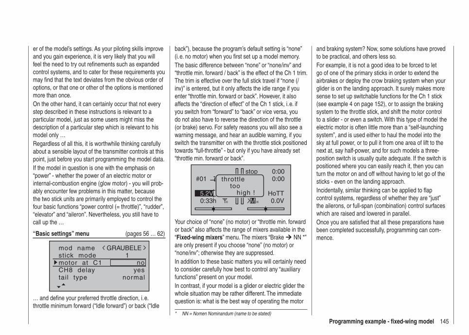
145Programming example - fi xed-wing model
er of the model’s settings. As your piloting skills improve and you gain experience, it is very likely that you will feel the need to try out refi nements such as expanded control systems, and to cater for these requirements you may fi nd that the text deviates from the obvious order of options, or that one or other of the options is mentioned more than once.On the other hand, it can certainly occur that not every step described in these instructions is relevant to a particular model, just as some users might miss the description of a particular step which is relevant to his model only …Regardless of all this, it is worthwhile thinking carefully about a sensible layout of the transmitter controls at this point, just before you start programming the model data.If the model in question is one with the emphasis on “power” - whether the power of an electric motor or internal-combustion engine (glow motor) - you will prob-ably encounter few problems in this matter, because the two stick units are primarily employed to control the four basic functions “power control (= throttle)”, “rudder”, “elevator” and “aileron”. Nevertheless, you still have to call up the …
“Basic settings” menu (pages 56 … 62)
mod namestick mode
CH8 delaymotor at C1
1
yesno
tail type normal
GRAUBELE
… and defi ne your preferred throttle direction, i. e. throttle minimum forward (“Idle forward”) or back (“Idle
back”), because the program’s default setting is “none” (i. e. no motor) when you fi rst set up a model memory.The basic difference between “none” or “none/inv” and “throttle min. forward / back” is the effect of the Ch 1 trim. The trim is effective over the full stick travel if “none (/inv)” is entered, but it only affects the idle range if you enter “throttle min. forward or back”. However, it also affects the “direction of effect” of the Ch 1 stick, i. e. if you switch from “forward” to “back” or vice versa, you do not also have to reverse the direction of the throttle (or brake) servo. For safety reasons you will also see a warning message, and hear an audible warning, if you switch the transmitter on with the throttle stick positioned towards “full-throttle” - but only if you have already set “throttle min. forward or back”.
#01
0:33h
stop 0:000:00
0.0V5.2V HoTT
M
throttletoo
high !
Your choice of “none” (no motor) or “throttle min. forward or back” also affects the range of mixers available in the “Fixed-wing mixers” menu. The mixers “Brake NN *” are only present if you choose “none” (no motor) or “none/inv”; otherwise they are suppressed.In addition to these basic matters you will certainly need to consider carefully how best to control any “auxiliary functions” present on your model.In contrast, if your model is a glider or electric glider the whole situation may be rather different. The immediate question is: what is the best way of operating the motor
and braking system? Now, some solutions have proved to be practical, and others less so.For example, it is not a good idea to be forced to let go of one of the primary sticks in order to extend the airbrakes or deploy the crow braking system when your glider is on the landing approach. It surely makes more sense to set up switchable functions for the Ch 1 stick (see example 4 on page 152), or to assign the braking system to the throttle stick, and shift the motor control to a slider - or even a switch. With this type of model the electric motor is often little more than a “self-launching system”, and is used either to haul the model into the sky at full power, or to pull it from one area of lift to the next at, say half-power, and for such models a three-position switch is usually quite adequate. If the switch is positioned where you can easily reach it, then you can turn the motor on and off without having to let go of the sticks - even on the landing approach.Incidentally, similar thinking can be applied to fl ap control systems, regardless of whether they are “just” the ailerons, or full-span (combination) control surfaces which are raised and lowered in parallel.Once you are satisfi ed that all these preparations have been completed successfully, programming can com-mence.
* NN = Nomen Nominandum (name to be stated)
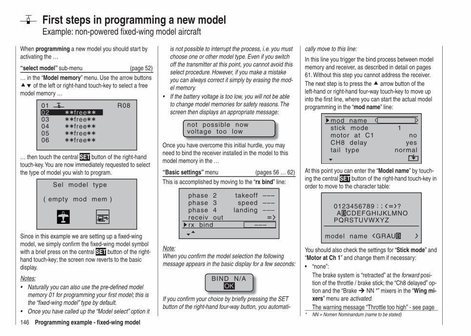
146 Programming example - fi xed-wing model
First steps in programming a new modelExample: non-powered fi xed-wing model aircraft
When programming a new model you should start by activating the …
“select model” sub-menu (page 52)
… in the “Model memory” menu. Use the arrow buttons of the left or right-hand touch-key to select a free
model memory …
030405
free0201
06
R08
freefreefreefree
… then touch the central SET button of the right-hand touch-key. You are now immediately requested to select the type of model you wish to program.
Sel model type
( empty mod mem )
Since in this example we are setting up a fi xed-wing model, we simply confi rm the fi xed-wing model symbol with a brief press on the central SET button of the right-hand touch-key; the screen now reverts to the basic display.
Notes:Naturally you can also use the pre-defi ned model • memory 01 for programming your fi rst model; this is the “fi xed-wing model” type by default.Once you have called up the “Model select” option it •
is not possible to interrupt the process, i. e. you must choose one or other model type. Even if you switch off the transmitter at this point, you cannot avoid this select procedure. However, if you make a mistake you can always correct it simply by erasing the mod-el memory.If the battery voltage is too low, you will not be able • to change model memories for safety reasons. The screen then displays an appropriate message:
not possible nowvoltage too low
Once you have overcome this initial hurdle, you may need to bind the receiver installed in the model to this model memory in the …
“Basic settings” menu (pages 56 … 62)
This is accomplished by moving to the “rx bind” line:
phase 3phase 4 landing
speed –––
receiv outrx bind –––
phase 2 takeoff
–––
–––
Note:When you confi rm the model selection the following message appears in the basic display for a few seconds:
BIND N/AOK
If you confi rm your choice by briefl y pressing the SET button of the right-hand four-way button, you automati-
cally move to this line:
In this line you trigger the bind process between model memory and receiver, as described in detail on pages 61. Without this step you cannot address the receiver.The next step is to press the arrow button of the left-hand or right-hand four-way touch-key to move up into the fi rst line, where you can start the actual model programming in the “mod name” line:
mod namestick mode
CH8 delaymotor at C1
1
yesno
tail type normal
At this point you can enter the “Model name” by touch-ing the central SET button of the right-hand touch-key in order to move to the character table:
0123456789
PQRSTUVWXYZ
model name
?: ;ABCDEFGHIJKLMNO
GRAUB
You should also check the settings for “Stick mode” and “Motor at Ch 1” and change them if necessary:
“none”:• The brake system is “retracted” at the forward posi-tion of the throttle / brake stick; the “Ch8 delayed” op-tion and the “Brake NN *” mixers in the “Wing mi-xers” menu are activated.The warning message “Throttle too high” - see page
* NN = Nomen Nominandum (name to be stated)

147Programming example - fi xed-wing model
28 - and the “Motor stop” option are disabled.“none/inv”:• The brake system is “retracted” at the back position of the throttle / brake stick; the “Ch8 delayed” option and the “Brake NN *” mixers in the “Wing mixers” menu are activated.The warning message “Throttle too high” - see page 28 - and the “Motor stop” option are disabled.“Throttle min. forward or rear”:• Ch 1 trim works forward or back. If the throttle stick is too far in the direction of “full-throttle” when you switch the transmitter on, you will be warned of this with the message “Throttle too high”.The “Motor stop” option is activated, and the “Brake
NN *” mixers in the “Wing mixers” menu are dis-abled.
Note:As mentioned previously, selecting “motor” or “no motor” also affects the range of mixers available in the “Fixed-wing mixers” menu. For this reason we shall initially consider “none” (no motor) in the following programming example.
In the next two lines you select the basic arrangement of the servos in the model, and inform the transmitter of your choice:
stick modemotor at C1
1no
tail type normalCH8 delay
aile/flap 2aile
yes
tail type: “normal”, “V-tail”, “delt/FlW” or
“2elev sv”aile/fl ap: 1 or 2 aileron servos and 0 or 2 fl ap
servos
Note:If your model is fi tted with only one camber-changing fl ap servo, you should still select “… 2FL”. Later, in the “Fixed-wing mixers” menu (see page 88), you should select the “AIL FL” mixer and set it to 0%. You can still exploit all the other mixers available at that point in the usual way.
At this juncture - if not before - you should check that the servos are connected to the receiver in the standard Graupner sequence:
Airbrakes or throttle / speed controller or speed controller (electric)Right flap servo
Flap servo or left flap servo
Rudder servo or V-tail
Aileron servo or left aileron servoElevator servo or V-tail
Right aileron servo
Auxiliary function
Receiver power supply
Notes:If you set up a V-tail, but the “up / down” and / or “left • / right” functions work the wrong way round, please refer to the table in the right-hand column on page 44 for the remedy. The same procedure can be used if you set up fl aperons (superimposed ailerons and fl aps), and they work the wrong way round.The following settings apply to a model with a “nor-• mal” tail and no motor (“none”); if your model has a V-tail, the settings can be adopted virtually unchanged. However, if the model is a delta or fl ying wing, the sit-
uation is not quite so straightforward. A special pro-gramming example covering this model type will be found in the section starting on page 158.
In the …
“Servo settings” menu (page 72)
S1S2S3
rev cent +trav
0%0%0%
100% 100%100% 100%100% 100%
0%0%
100% 100%100% 100%
S4S5
… ... you can set various parameters relating to the ser-vos, i. e. “direction of rotation”, “neutral setting” and “servo travel”, to suit the requirements of the model.By “requirements” we mean adjustments to servo centre and servo travel which are needed to compensate for minor tolerances in servos and slight inaccuracies on the model itself.
Note:The facilities provided in this menu for setting asym-metrical servo travels are NOT intended as a means of setting up differential travel on ailerons and / or camber-changing fl aps. There are more suitable options for this in the form of specifi c functions in the “Fixed-wing mixers” menu; see the fi rst two options in the picture on the right.
Once you have completed the settings described thus far, a fi xed-wing or powered model aircraft (the latter if you enter the idle direction of the throttle stick in the “Motor at Ch 1” line of the “Basic settings” menu) will, in principle, fl y.However, there are no “refi nements” in this set-up, and
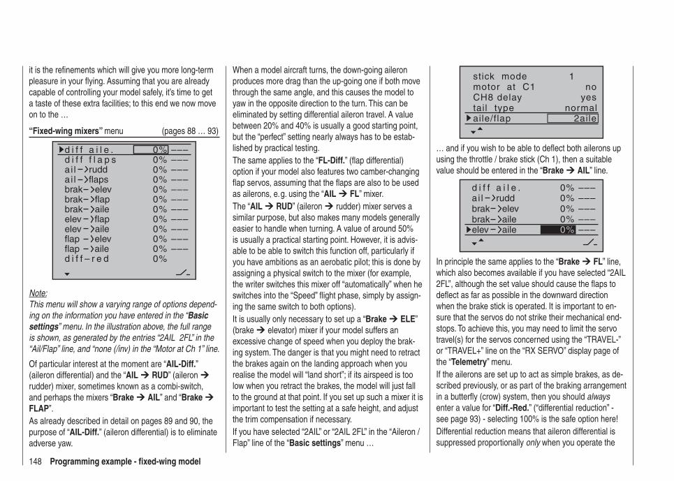
148 Programming example - fi xed-wing model
it is the refi nements which will give you more long-term pleasure in your fl ying. Assuming that you are already capable of controlling your model safely, it’s time to get a taste of these extra facilities; to this end we now move on to the …
“Fixed-wing mixers” menu (pages 88 … 93)
0%
0%0%
0%0%0%0%0%0%0%0%0%
–––––––––––––––––––––––––––––––––
ai la i l
d i f f a i l e .
ruddflaps
brakbrakbrak
elevflapaile
elevelevflap
flapaileelev
flapd i f f – r e d
aile
d i f f f l a p s
Note:This menu will show a varying range of options depend-ing on the information you have entered in the “Basic settings” menu. In the illustration above, the full range is shown, as generated by the entries “2AIL 2FL” in the “Ail/Flap” line, and “none (/inv) in the “Motor at Ch 1” line.
Of particular interest at the moment are “AIL-Diff.” (aileron differential) and the “AIL RUD” (aileron rudder) mixer, sometimes known as a combi-switch, and perhaps the mixers “Brake AIL” and “Brake FLAP”.As already described in detail on pages 89 and 90, the purpose of “AIL-Diff.” (aileron differential) is to eliminate adverse yaw.
When a model aircraft turns, the down-going aileron produces more drag than the up-going one if both move through the same angle, and this causes the model to yaw in the opposite direction to the turn. This can be eliminated by setting differential aileron travel. A value between 20% and 40% is usually a good starting point, but the “perfect” setting nearly always has to be estab-lished by practical testing.The same applies to the “FL-Diff.” (fl ap differential) option if your model also features two camber-changing fl ap servos, assuming that the fl aps are also to be used as ailerons, e. g. using the “AIL FL” mixer.The “AIL RUD” (aileron rudder) mixer serves a similar purpose, but also makes many models generally easier to handle when turning. A value of around 50% is usually a practical starting point. However, it is advis-able to be able to switch this function off, particularly if you have ambitions as an aerobatic pilot; this is done by assigning a physical switch to the mixer (for example, the writer switches this mixer off “automatically” when he switches into the “Speed” fl ight phase, simply by assign-ing the same switch to both options).It is usually only necessary to set up a “Brake ELE” (brake elevator) mixer if your model suffers an excessive change of speed when you deploy the brak-ing system. The danger is that you might need to retract the brakes again on the landing approach when you realise the model will “land short”; if its airspeed is too low when you retract the brakes, the model will just fall to the ground at that point. If you set up such a mixer it is important to test the setting at a safe height, and adjust the trim compensation if necessary.If you have selected “2AIL” or “2AIL 2FL” in the “Aileron / Flap” line of the “Basic settings” menu …
stick modemotor at C1
1no
tail type normalCH8 delay
aile/flap 2aile
yes
… and if you wish to be able to defl ect both ailerons up using the throttle / brake stick (Ch 1), then a suitable value should be entered in the “Brake AIL” line.
0%
0%0%
0%
–––––––––––––––0%
ai ld i f f a i l e .
ruddbrakbrak
elevaile
elev aile
In principle the same applies to the “Brake FL” line, which also becomes available if you have selected “2AIL 2FL”, although the set value should cause the fl aps to defl ect as far as possible in the downward direction when the brake stick is operated. It is important to en-sure that the servos do not strike their mechanical end-stops. To achieve this, you may need to limit the servo travel(s) for the servos concerned using the “TRAVEL-” or “TRAVEL+” line on the “RX SERVO” display page of the “Telemetry” menu.If the ailerons are set up to act as simple brakes, as de-scribed previously, or as part of the braking arrangement in a butterfl y (crow) system, then you should always enter a value for “Diff.-Red.” (“differential reduction” - see page 93) - selecting 100% is the safe option here!Differential reduction means that aileron differential is suppressed proportionally only when you operate the
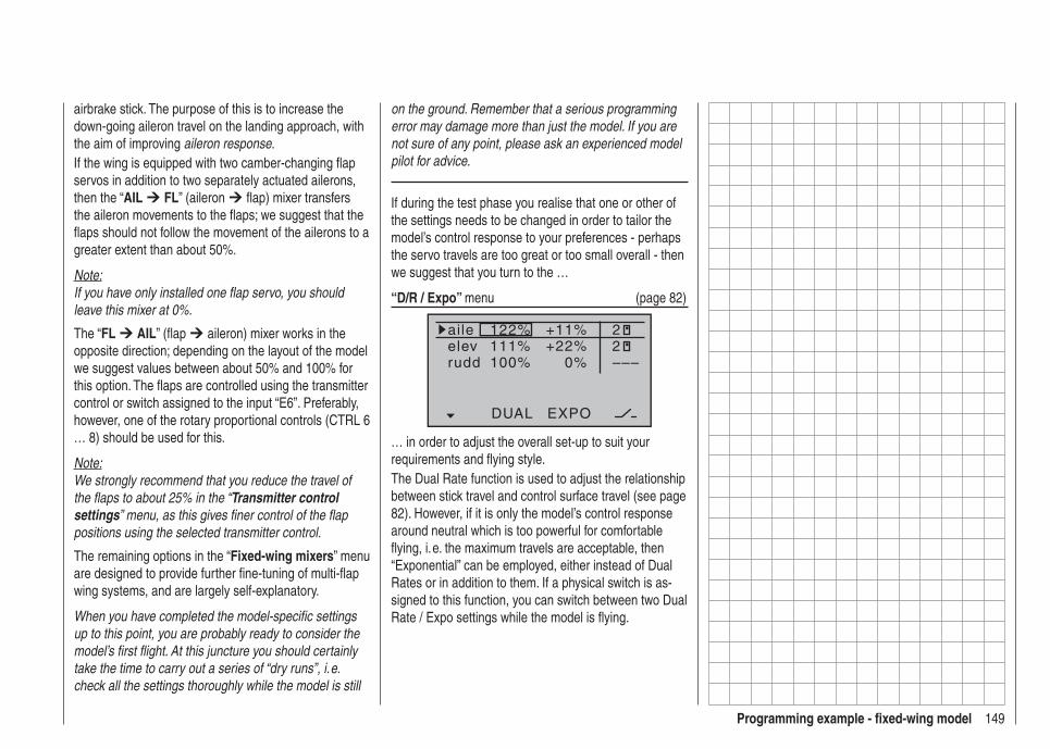
149Programming example - fi xed-wing model
airbrake stick. The purpose of this is to increase the down-going aileron travel on the landing approach, with the aim of improving aileron response.If the wing is equipped with two camber-changing fl ap servos in addition to two separately actuated ailerons, then the “AIL FL” (aileron fl ap) mixer transfers the aileron movements to the fl aps; we suggest that the fl aps should not follow the movement of the ailerons to a greater extent than about 50%.
Note:If you have only installed one fl ap servo, you should leave this mixer at 0%.
The “FL AIL” (fl ap aileron) mixer works in the opposite direction; depending on the layout of the model we suggest values between about 50% and 100% for this option. The fl aps are controlled using the transmitter control or switch assigned to the input “E6”. Preferably, however, one of the rotary proportional controls (CTRL 6 … 8) should be used for this.
Note:We strongly recommend that you reduce the travel of the fl aps to about 25% in the “Transmitter control settings” menu, as this gives fi ner control of the fl ap positions using the selected transmitter control.
The remaining options in the “Fixed-wing mixers” menu are designed to provide further fi ne-tuning of multi-fl ap wing systems, and are largely self-explanatory.
When you have completed the model-specifi c settings up to this point, you are probably ready to consider the model’s fi rst fl ight. At this juncture you should certainly take the time to carry out a series of “dry runs”, i. e. check all the settings thoroughly while the model is still
on the ground. Remember that a serious programming error may damage more than just the model. If you are not sure of any point, please ask an experienced model pilot for advice.
If during the test phase you realise that one or other of the settings needs to be changed in order to tailor the model’s control response to your preferences - perhaps the servo travels are too great or too small overall - then we suggest that you turn to the …
“D/R / Expo” menu (page 82)
122%
100%111%
+11%
0%
aileelevrudd
DUAL EXPO
22–––
+22%
… in order to adjust the overall set-up to suit your requirements and fl ying style.The Dual Rate function is used to adjust the relationship between stick travel and control surface travel (see page 82). However, if it is only the model’s control response around neutral which is too powerful for comfortable fl ying, i. e. the maximum travels are acceptable, then “Exponential” can be employed, either instead of Dual Rates or in addition to them. If a physical switch is as-signed to this function, you can switch between two Dual Rate / Expo settings while the model is fl ying.
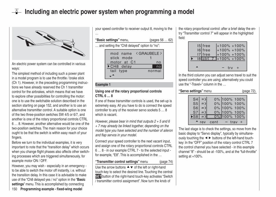
150 Programming example - fi xed-wing model
Including an electric power system when programming a model
An electric power system can be controlled in various ways:The simplest method of including such a power plant in a model program is to use the throttle / brake stick (Ch 1). However, in the preceding programming instruc-tions we have already reserved the Ch 1 transmitter control for the airbrakes, which means that we have to explore other possibilities for controlling the motor: one is to use the switchable solution described in the section starting on page 152, and another is to use an alternative transmitter control. A suitable option is one of the two three-position switches SW 4/5 or 6/7, and another is one of the rotary proportional controls CTRL 6 … 8. However, another alternative would be one of the two-position switches. The main reason for your choice ought to be that the switch is within easy reach of your fi ngers.Before we turn to the individual examples, it is very important to note that the “transition delay” which occurs when you change fl ight phases also affects other switch-ing processes which are triggered simultaneously, for example motor ON / OFF.However, you may wish - especially in an emergency - to be able to switch the motor off instantly, i. e. without the transition delay. In this case it is advisable to make use of the “Ch8 delayed yes / no” option in the “Basic settings” menu. This is accomplished by connecting
your speed controller to receiver output 8, moving to the …
“Basic settings” menu, (pages 56 … 62)
… and setting the “Ch8 delayed” option to “no”:
mod namestick mode
CH8 delaymotor at C1
1no
tail type normal
GRAUBELE
no
Example 1
Using one of the rotary proportional controls CTRL 6 … 8If one of these transmitter controls is used, the set-up is extremely easy. All you have to do is connect the speed controller to any of the receiver servo sockets 5 … 8 which is vacant.
However, please bear in mind that outputs 2 + 5 and 6 + 7 may already be linked together, depending on the model type you have selected and the number of aileron and fl ap servos in your model.
Connect your speed controller to the next vacant input, and assign one of the rotary proportional controls CTRL 6 … 8 - in our example CTRL 7 - to the selected input - for example, “E8”. This is accomplished in the …
“Transmitter control settings” menu (page 74)
Use the arrow buttons of the left or right-hand touch-key to select the desired line. Touching the central SET button of the right-hand touch-key activates “Switch / transmitter control assignment”. Now turn the knob of
the rotary proportional control: after a brief delay the en-try “Transmitter control 7” will appear in the highlighted fi eld:
I5I6I7
+trv
I8 ctr l 7freefree
+100% +100%+100%
+100% +100%+100% +100%
+100%free
In the third column you can adjust servo travel to suit the speed controller you are using; alternatively you could use the “-Travel+” column in the …
“Servo settings” menu (page 72).
S4S5S6
rev cent +trav
0%0%0%
100% 100%100% 100%100% 100%
0%0%
100% 100%100% 100%
S7S8
The last stage is to check the settings, so move from the basic display to “Servo display”, typically by simultane-ously touching the buttons of the left-hand touch-key: In the “OFF” position of the rotary control CTRL 7 the control channel you have selected - in this example channel “8” - should be at -100%, and at the “full-throttle” setting at +100%.
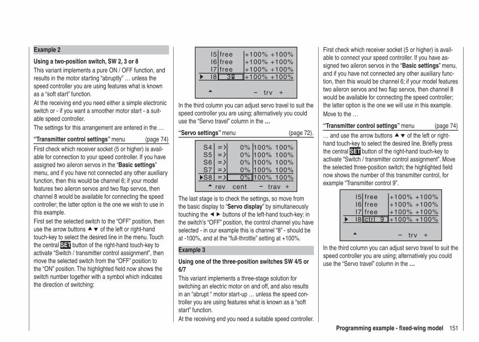
151Programming example - fi xed-wing model
I5I6I7
+trv
I8freefree
+100% +100%+100%
+100% +100%+100% +100%
+100%free
3
In the third column you can adjust servo travel to suit the speed controller you are using; alternatively you could use the “Servo travel” column in the …
“Servo settings” menu (page 72).
S4S5S6
rev cent +trav
0%0%0%
100% 100%100% 100%100% 100%
0%0%
100% 100%100% 100%
S7S8
The last stage is to check the settings, so move from the basic display to “Servo display” by simultaneously touching the buttons of the left-hand touch-key: in the switch’s “OFF” position, the control channel you have selected - in our example this is channel “8” - should be at -100%, and at the “full-throttle” setting at +100%.
Example 3
Using one of the three-position switches SW 4/5 or 6/7This variant implements a three-stage solution for switching an electric motor on and off, and also results in an “abrupt “ motor start-up … unless the speed con-troller you are using features what is known as a “soft start” function.At the receiving end you need a suitable speed controller.
Example 2
Using a two-position switch, SW 2, 3 or 8This variant implements a pure ON / OFF function, and results in the motor starting “abruptly” … unless the speed controller you are using features what is known as a “soft start” function.At the receiving end you need either a simple electronic switch or - if you want a smoother motor start - a suit-able speed controller.The settings for this arrangement are entered in the …
“Transmitter control settings” menu (page 74)
First check which receiver socket (5 or higher) is avail-able for connection to your speed controller. If you have assigned two aileron servos in the “Basic settings” menu, and if you have not connected any other auxiliary function, then this would be channel 6; if your model features two aileron servos and two fl ap servos, then channel 8 would be available for connecting the speed controller; the latter option is the one we wish to use in this example.First set the selected switch to the “OFF” position, then use the arrow buttons of the left or right-hand touch-key to select the desired line in the menu. Touch the central SET button of the right-hand touch-key to activate “Switch / transmitter control assignment”, then move the selected switch from the “OFF” position to the “ON” position. The highlighted fi eld now shows the switch number together with a symbol which indicates the direction of switching:
First check which receiver socket (5 or higher) is avail-able to connect your speed controller. If you have as-signed two aileron servos in the “Basic settings” menu, and if you have not connected any other auxiliary func-tion, then this would be channel 6; if your model features two aileron servos and two fl ap servos, then channel 8 would be available for connecting the speed controller; the latter option is the one we will use in this example.Move to the …
“Transmitter control settings” menu (page 74)
… and use the arrow buttons of the left or right-hand touch-key to select the desired line. Briefl y press the central SET button of the right-hand touch-key to activate “Switch / transmitter control assignment”. Move the selected three-position switch; the highlighted fi eld now shows the number of this transmitter control, for example “Transmitter control 9”.
I5I6I7
+trv
I8 ctr l 9freefree
+100% +100%+100%
+100% +100%+100% +100%
+100%free
In the third column you can adjust servo travel to suit the speed controller you are using; alternatively you could use the “Servo travel” column in the …
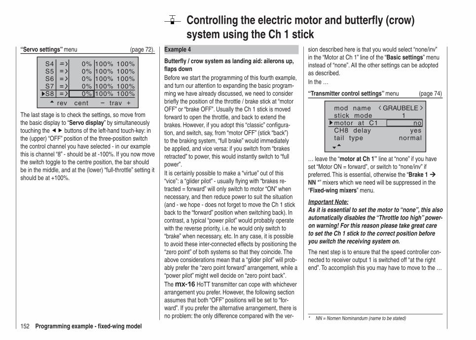
152 Programming example - fi xed-wing model
Controlling the electric motor and butterfl y (crow) system using the Ch 1 stick
Example 4
Butterfl y / crow system as landing aid: ailerons up, fl aps downBefore we start the programming of this fourth example, and turn our attention to expanding the basic program-ming we have already discussed, we need to consider briefl y the position of the throttle / brake stick at “motor OFF” or “brake OFF”. Usually the Ch 1 stick is moved forward to open the throttle, and back to extend the brakes. However, if you adopt this “classic” confi gura-tion, and switch, say, from “motor OFF” (stick “back”) to the braking system, “full brake” would immediately be applied, and vice versa: if you switch from “brakes retracted” to power, this would instantly switch to “full power”.It is certainly possible to make a “virtue” out of this “vice”: a “glider pilot” - usually fl ying with “brakes re-tracted = forward” will only switch to motor “ON” when necessary, and then reduce power to suit the situation (and - we hope - does not forget to move the Ch 1 stick back to the “forward” position when switching back). In contrast, a typical “power pilot” would probably operate with the reverse priority, i. e. he would only switch to “brake” when necessary, etc. In any case, it is possible to avoid these inter-connected effects by positioning the “zero point” of both systems so that they coincide. The above considerations mean that a “glider pilot” will prob-ably prefer the “zero point forward” arrangement, while a “power pilot” might well decide on “zero point back”.The mx-16 HoTT transmitter can cope with whichever arrangement you prefer. However, the following section assumes that both “OFF” positions will be set to “for-ward”. If you prefer the alternative arrangement, there is no problem: the only difference compared with the ver-
sion described here is that you would select “none/inv” in the “Motor at Ch 1” line of the “Basic settings” menu instead of “none”. All the other settings can be adopted as described.In the …
“Transmitter control settings” menu (page 74)
mod namestick mode
CH8 delaymotor at C1
1
yesno
tail type normal
GRAUBELE
… leave the “motor at Ch 1” line at “none” if you have set “Motor ON = forward”, or switch to “none/inv” if preferred. This is essential, otherwise the “Brake 1 NN *” mixers which we need will be suppressed in the “Fixed-wing mixers” menu.
Important Note:As it is essential to set the motor to “none”, this also automatically disables the “Throttle too high” power-on warning! For this reason please take great care to set the Ch 1 stick to the correct position before you switch the receiving system on.
The next step is to ensure that the speed controller con-nected to receiver output 1 is switched off “at the right end”. To accomplish this you may have to move to the …
* NN = Nomen Nominandum (name to be stated)
“Servo settings” menu (page 72).
S4S5S6
rev cent +trav
0%0%0%
100% 100%100% 100%100% 100%
0%0%
100% 100%100% 100%
S7S8
The last stage is to check the settings, so move from the basic display to “Servo display” by simultaneously touching the buttons of the left-hand touch-key: in the (upper) “OFF” position of the three-position switch the control channel you have selected - in our example this is channel “8” - should be at -100%. If you now move the switch toggle to the centre position, the bar should be in the middle, and at the (lower) “full-throttle” setting it should be at +100%.
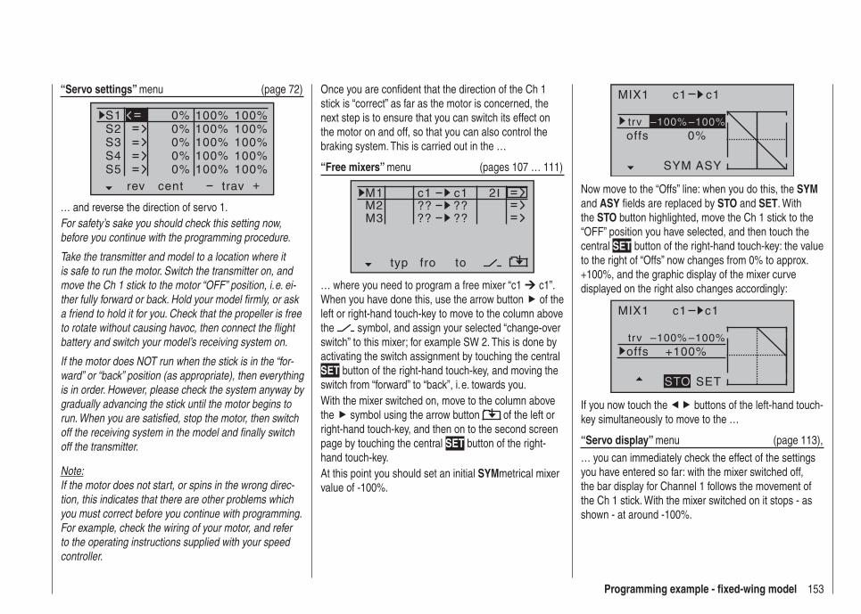
153Programming example - fi xed-wing model
MIX1 c1 c1
trv0%offs
ASYSYM
–100% –100%
Now move to the “Offs” line: when you do this, the SYM and ASY fi elds are replaced by STO and SET. With the STO button highlighted, move the Ch 1 stick to the “OFF” position you have selected, and then touch the central SET button of the right-hand touch-key: the value to the right of “Offs” now changes from 0% to approx. +100%, and the graphic display of the mixer curve displayed on the right also changes accordingly:
MIX1 c1 c1
trv+100%offs
SETSTO
–100% –100%
If you now touch the buttons of the left-hand touch-key simultaneously to move to the …
“Servo display” menu (page 113),
… you can immediately check the effect of the settings you have entered so far: with the mixer switched off, the bar display for Channel 1 follows the movement of the Ch 1 stick. With the mixer switched on it stops - as shown - at around -100%.
Once you are confi dent that the direction of the Ch 1 stick is “correct” as far as the motor is concerned, the next step is to ensure that you can switch its effect on the motor on and off, so that you can also control the braking system. This is carried out in the …
“Free mixers” menu (pages 107 … 111)
typ fro to
M1M2M3
?? ??c1
??
c1
??
2
… where you need to program a free mixer “c1 c1”. When you have done this, use the arrow button of the left or right-hand touch-key to move to the column above the symbol, and assign your selected “change-over switch” to this mixer; for example SW 2. This is done by activating the switch assignment by touching the central SET button of the right-hand touch-key, and moving the switch from “forward” to “back”, i. e. towards you.With the mixer switched on, move to the column above the symbol using the arrow button of the left or right-hand touch-key, and then on to the second screen page by touching the central SET button of the right-hand touch-key.At this point you should set an initial SYMmetrical mixer value of -100%.
“Servo settings” menu (page 72)
S1S2S3
rev cent +trav
0%0%0%
100% 100%100% 100%100% 100%
0%0%
100% 100%100% 100%
S4S5
… and reverse the direction of servo 1.For safety’s sake you should check this setting now, before you continue with the programming procedure.
Take the transmitter and model to a location where it is safe to run the motor. Switch the transmitter on, and move the Ch 1 stick to the motor “OFF” position, i. e. ei-ther fully forward or back. Hold your model fi rmly, or ask a friend to hold it for you. Check that the propeller is free to rotate without causing havoc, then connect the fl ight battery and switch your model’s receiving system on.
If the motor does NOT run when the stick is in the “for-ward” or “back” position (as appropriate), then everything is in order. However, please check the system anyway by gradually advancing the stick until the motor begins to run. When you are satisfi ed, stop the motor, then switch off the receiving system in the model and fi nally switch off the transmitter.
Note:If the motor does not start, or spins in the wrong direc-tion, this indicates that there are other problems which you must correct before you continue with programming. For example, check the wiring of your motor, and refer to the operating instructions supplied with your speed controller.
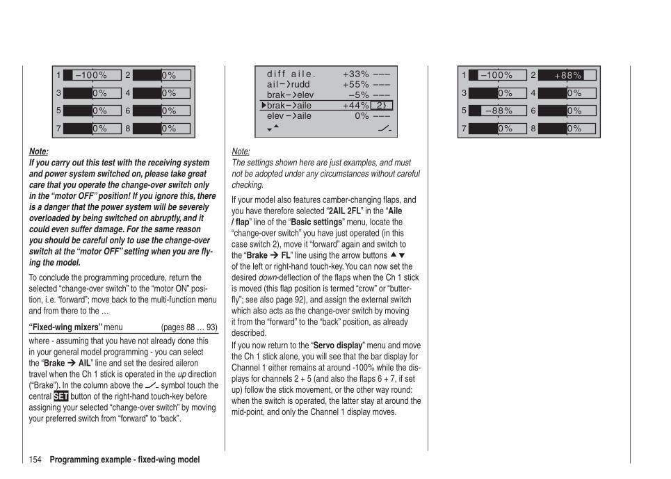
154 Programming example - fi xed-wing model
+33%
–5%+55%
–––––––––2
–––0%+44%
ai ld i f f a i l e .
ruddbrakbrak
elevaile
elev aile
Note:The settings shown here are just examples, and must not be adopted under any circumstances without careful checking.
If your model also features camber-changing fl aps, and you have therefore selected “2AIL 2FL” in the “Aile / fl ap” line of the “Basic settings” menu, locate the “change-over switch” you have just operated (in this case switch 2), move it “forward” again and switch to the “Brake FL” line using the arrow buttons of the left or right-hand touch-key. You can now set the desired down-defl ection of the fl aps when the Ch 1 stick is moved (this fl ap position is termed “crow” or “butter-fl y”; see also page 92), and assign the external switch which also acts as the change-over switch by moving it from the “forward” to the “back” position, as already described.If you now return to the “Servo display” menu and move the Ch 1 stick alone, you will see that the bar display for Channel 1 either remains at around -100% while the dis-plays for channels 2 + 5 (and also the fl aps 6 + 7, if set up) follow the stick movement, or the other way round: when the switch is operated, the latter stay at around the mid-point, and only the Channel 1 display moves.
1
3
5
7
2
4
6
8
0%
0%
0%
–100%
0%
–88%
0%
+88%1
3
5
7
2
4
6
8
0%
0%
0%
0%
–100%
0%
0%
0%
Note:If you carry out this test with the receiving system and power system switched on, please take great care that you operate the change-over switch only in the “motor OFF” position! If you ignore this, there is a danger that the power system will be severely overloaded by being switched on abruptly, and it could even suffer damage. For the same reason you should be careful only to use the change-over switch at the “motor OFF” setting when you are fl y-ing the model.
To conclude the programming procedure, return the selected “change-over switch” to the “motor ON” posi-tion, i. e. “forward”; move back to the multi-function menu and from there to the …
“Fixed-wing mixers” menu (pages 88 … 93)
where - assuming that you have not already done this in your general model programming - you can select the “Brake AIL” line and set the desired aileron travel when the Ch 1 stick is operated in the up direction (“Brake”). In the column above the symbol touch the central SET button of the right-hand touch-key before assigning your selected “change-over switch” by moving your preferred switch from “forward” to “back”.
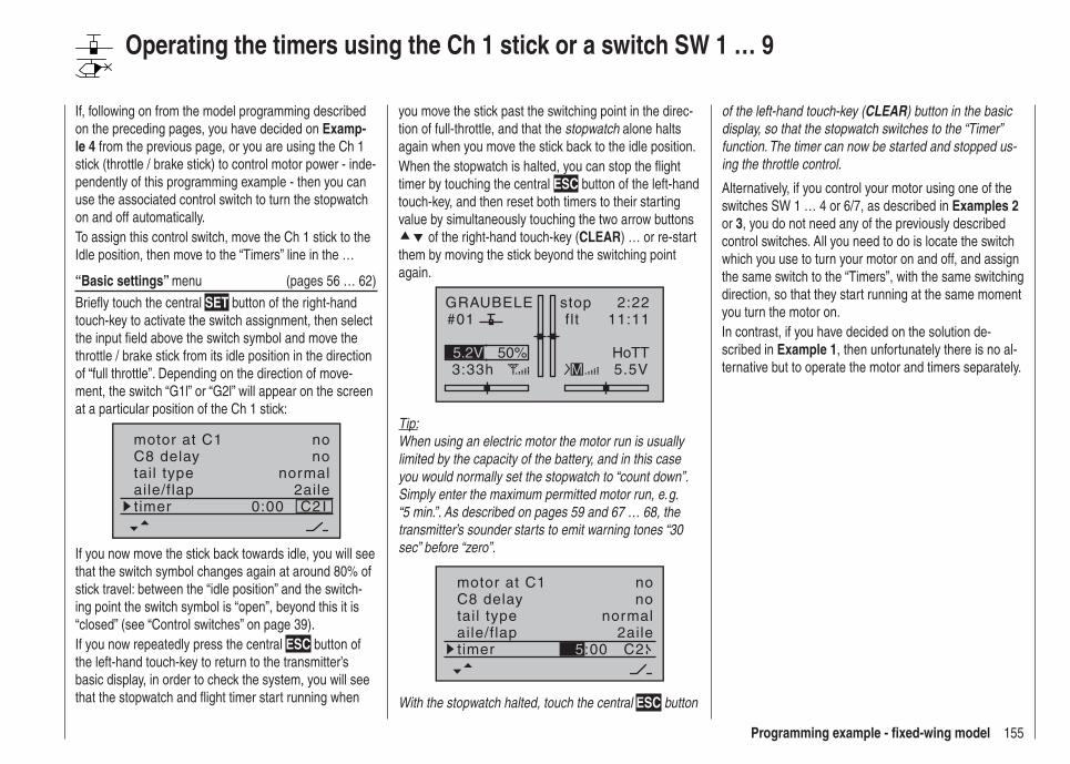
155Programming example - fi xed-wing model
you move the stick past the switching point in the direc-tion of full-throttle, and that the stopwatch alone halts again when you move the stick back to the idle position.When the stopwatch is halted, you can stop the fl ight timer by touching the central ESC button of the left-hand touch-key, and then reset both timers to their starting value by simultaneously touching the two arrow buttons
of the right-hand touch-key (CLEAR) … or re-start them by moving the stick beyond the switching point again.
GRAUBELE#01
3:33h
stop flt
2:2211:11
5.5V50%5.2V HoTT
M
Tip:When using an electric motor the motor run is usually limited by the capacity of the battery, and in this case you would normally set the stopwatch to “count down”. Simply enter the maximum permitted motor run, e. g. “5 min.”. As described on pages 59 and 67 … 68, the transmitter’s sounder starts to emit warning tones “30 sec” before “zero”.
tail typeC8 delay
normalno
aile/flap 2ailetimer C2
motor at C1 no
5:00
With the stopwatch halted, touch the central ESC button
of the left-hand touch-key (CLEAR) button in the basic display, so that the stopwatch switches to the “Timer” function. The timer can now be started and stopped us-ing the throttle control.
Alternatively, if you control your motor using one of the switches SW 1 … 4 or 6/7, as described in Examples 2 or 3, you do not need any of the previously described control switches. All you need to do is locate the switch which you use to turn your motor on and off, and assign the same switch to the “Timers”, with the same switching direction, so that they start running at the same moment you turn the motor on.In contrast, if you have decided on the solution de-scribed in Example 1, then unfortunately there is no al-ternative but to operate the motor and timers separately.
If, following on from the model programming described on the preceding pages, you have decided on Examp-le 4 from the previous page, or you are using the Ch 1 stick (throttle / brake stick) to control motor power - inde-pendently of this programming example - then you can use the associated control switch to turn the stopwatch on and off automatically.To assign this control switch, move the Ch 1 stick to the Idle position, then move to the “Timers” line in the …
“Basic settings” menu (pages 56 … 62)
Briefl y touch the central SET button of the right-hand touch-key to activate the switch assignment, then select the input fi eld above the switch symbol and move the throttle / brake stick from its idle position in the direction of “full throttle”. Depending on the direction of move-ment, the switch “G1l” or “G2l” will appear on the screen at a particular position of the Ch 1 stick:
tail typeC8 delay
normalno
aile/flap 2ailetimer C20:00
motor at C1 no
If you now move the stick back towards idle, you will see that the switch symbol changes again at around 80% of stick travel: between the “idle position” and the switch-ing point the switch symbol is “open”, beyond this it is “closed” (see “Control switches” on page 39). If you now repeatedly press the central ESC button of the left-hand touch-key to return to the transmitter’s basic display, in order to check the system, you will see that the stopwatch and fl ight timer start running when
Operating the timers using the Ch 1 stick or a switch SW 1 … 9
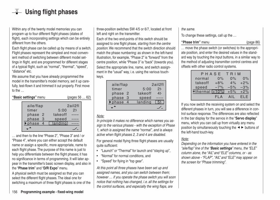
156 Programming example - fi xed-wing model
Using fl ight phases
Within any of the twenty model memories you can program up to four different fl ight phases (states of fl ight), each incorporating settings which can be entirely different from the others.Each fl ight phase can be called up by means of a switch. Flight phases represent the simplest and most conven-ient method of switching between different model set-tings in fl ight, and are programmed for different stages of a typical fl ight, such as “normal”, “thermal”, “speed”, “distance” etc.We assume that you have already programmed the model in the transmitter’s model memory, set it up care-fully, test-fl own it and trimmed it out properly. First move to the …
“Basic settings” menu (pages 56 … 62)
aile/flap 2ail2fltimer 5:00 2phase 2phase 3phase 4
takeoff
landingspeed
–––––––––
… and then to the line “Phase 2”, “Phase 3” and / or “Phase 4”, where you can either accept the default name or assign a specifi c, more appropriate, name to each fl ight phase. The purpose of this name is just to help you differentiate between the fl ight phases; it has no signifi cance in terms of programming. It will later ap-pear in the transmitter’s basic screen display, and also in the “Phase trim” and “D/R Expo” menu.A physical switch must be assigned so that you can select the different fl ight phases. The ideal one for switching a maximum of three fl ight phases is one of the
three-position switches SW 4/5 or 6/7, located at front left and right on the transmitter.Each of the two end-points of this switch should be assigned to one fl ight phase, starting from the centre position. We recommend that the switch direction should match the phase numbering: as shown in the left-hand illustration, for example, “Phase 2” is “forward” from the centre position, while “Phase 3” is “back” (towards you).Select the appropriate line, name, and switch assign-ment in the “usual” way, i. e. using the various touch-keys.
5:00 2
–––4
5
aile/flap 2ail2fltimerphase 2phase 3phase 4
takeoff
landingspeed
Note:In principle it makes no difference which names you as-sign to the various phases - with the exception of Phase 1, which is assigned the name “normal”, and is always active when fl ight phases 2, 3 and 4 are disabled.
For general model fl ying three fl ight phases are usually quite suffi cient:
“Launch” or “Thermal” for launch and “staying up”,• “Normal” for normal conditions, and• “Speed” for fl ying in “top gear”.•
At this point all three phases have been set up and assigned names, and you can switch between them; however … if you operate the phase switch you will soon notice that nothing has changed, i. e. all the settings for the control surfaces, and especially the wing fl aps, are
the same.
To change these settings, call up the …
“Phase trim” menu (page 86)
… move the phase switch (or switches) to the appropri-ate position, and enter the desired values in the stand-ard way by touching the input buttons, in a similar way to the method of adjusting transmitter control centres and offsets with other radio control systems.
normal 0%0%0%+2%4%+8%–3%–5%–7%+2%+5%+10%
P H A S E T R I M
takeoffspeedthermal
AIL ELEFLA
If you now switch the receiving system on and select the different phases in turn, you will see a difference in con-trol surface response. The differences are also refl ected in the bar display for the servos in the “Servo display” menu, which you can call up from virtually any menu position by simultaneously touching the buttons of the left-hand touch-key.
Note:Depending on the information you have entered in the “aile/fl ap” line of the “Basic settings” menu, the “ELE” column alone, the “AIL” and “ELE” columns, or - as shown above - “FLAP”, “AIL” and “ELE” may appear on the screen for “Phase trimming”.
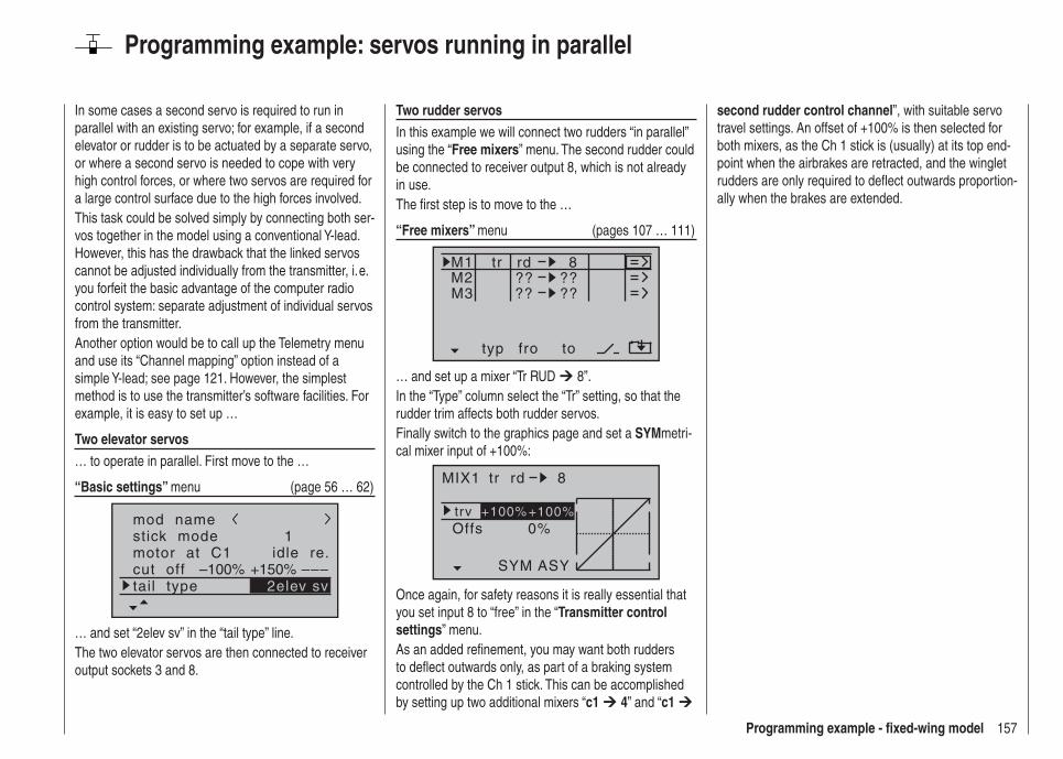
157Programming example - fi xed-wing model
Programming example: servos running in parallel
In some cases a second servo is required to run in parallel with an existing servo; for example, if a second elevator or rudder is to be actuated by a separate servo, or where a second servo is needed to cope with very high control forces, or where two servos are required for a large control surface due to the high forces involved.This task could be solved simply by connecting both ser-vos together in the model using a conventional Y-lead. However, this has the drawback that the linked servos cannot be adjusted individually from the transmitter, i. e. you forfeit the basic advantage of the computer radio control system: separate adjustment of individual servos from the transmitter.Another option would be to call up the Telemetry menu and use its “Channel mapping” option instead of a simple Y-lead; see page 121. However, the simplest method is to use the transmitter’s software facilities. For example, it is easy to set up …
Two elevator servos… to operate in parallel. First move to the …
“Basic settings” menu (page 56 … 62)
mod namestick modemotor at C1
1idle re.
tail typecut off +150%–100% –––
2elev sv
… and set “2elev sv” in the “tail type” line.The two elevator servos are then connected to receiver output sockets 3 and 8.
Two rudder servosIn this example we will connect two rudders “in parallel” using the “Free mixers” menu. The second rudder could be connected to receiver output 8, which is not already in use.The fi rst step is to move to the …
“Free mixers” menu (pages 107 … 111)
typ fro to
M1M2M3
?? ??rd
??
8
??
tr
… and set up a mixer “Tr RUD 8”.In the “Type” column select the “Tr” setting, so that the rudder trim affects both rudder servos.Finally switch to the graphics page and set a SYMmetri-cal mixer input of +100%:
MIX1 rd 8
trv0%Offs
ASYSYM
+100% +100%
tr
Once again, for safety reasons it is really essential that you set input 8 to “free” in the “Transmitter control settings” menu.As an added refi nement, you may want both rudders to defl ect outwards only, as part of a braking system controlled by the Ch 1 stick. This can be accomplished by setting up two additional mixers “c1 4” and “c1
second rudder control channel”, with suitable servo travel settings. An offset of +100% is then selected for both mixers, as the Ch 1 stick is (usually) at its top end-point when the airbrakes are retracted, and the winglet rudders are only required to defl ect outwards proportion-ally when the brakes are extended.
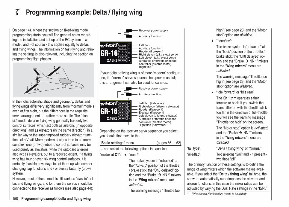
158 Programming example: delta and fl ying wing
On page 144, where the section on fi xed-wing model programming starts, you will fi nd general notes regard-ing the installation and set-up of the RC system in a model, and - of course - this applies equally to deltas and fl ying wings. The information on test-fl ying and refi n-ing the settings is also relevant, including the section on programming fl ight phases.
left
right
In their characteristic shape and geometry, deltas and fl ying wings differ very signifi cantly from “normal” models even at fi rst sight, but the differences in the requisite servo arrangement are rather more subtle. The “clas-sic” model delta or fl ying wing generally has only two control surfaces, which act both as ailerons (in opposite directions) and as elevators (in the same direction), in a similar way to the superimposed rudder / elevator func-tions of a V-tail. More modern designs tend to be more complex; one (or two) inboard control surfaces may be used purely as elevators, while the outboard ailerons also act as elevators, but to a reduced extent. If a fl ying wing has four or even six wing control surfaces, it is certainly feasible nowadays to set them up with camber-changing fl ap functions and / or even a butterfl y (crow) system.However, most of these models still rank as “classic” del-tas and fl ying wings, and for them the servos should be connected to the receiver as follows (see also page 44):
Airbrakes or throttle or speed controller (electric motor)Right flap
Left flap
Rudder (if present)
Left elevon (ail. / elev.) servoRight elevon (ail. / elev.) servo
Auxiliary function
Auxiliary function
Receiver power supply
If your delta or fl ying wing is of more “modern” confi gura-tion, the “normal” servo sequence has proved useful; this arrangement can also be used for canards:
Airbrakes or throttle or speed controller (electric motor)Right flap (/ elevator)
Left flap (/ elevator)
Rudder (if present)
Left elevon (aileron / elevator)Elevator (if present)
Right elevon (aileron / elevator)
Auxiliary function
Receiver power supply
Depending on the receiver servo sequence you select, you should fi rst move to the …
“Basic settings” menu (pages 56 … 62)
… and select the following options in each line:
“motor at C1”: • “none”:
The brake system is “retracted” at the “forward” position of the throttle / brake stick; the “Ch8 delayed” op-tion and the “Brake NN *” mixers in the “Wing mixers” menu are activated.
The warning message “Throttle too
Programming example: Delta / fl ying wing
high” (see page 28) and the “Motor stop” option are disabled.
• “none/inv”:
The brake system is “retracted” at the “back” position of the throttle / brake stick; the “Ch8 delayed” op-tion and the “Brake NN *” mixers in the “Wing mixers” menu are activated.
The warning message “Throttle too high” (see page 28) and the “Motor stop” option are disabled.
• “Idle forward” or “Idle rear”
The Ch 1 trim operates either forward or back. If you switch the transmitter on with the throttle stick too far in the direction of full-throttle, you will see the warning message “Throttle too high” on the screen.
The “Motor stop” option is activated, and the “Brake NN *” mixers in the “Wing mixers” menu are disabled.
“tail type”: “Delta / fl ying wing” or “Normal”
“aile/fl ap”: Two ailerons “2ail” and - if present - two fl aps “2fl ”.
The primary function of these settings is to defi ne the range of wing mixers which the software makes avail-able. If you select the “Delta / fl ying wing” tail type, the software automatically superimposes the elevator and aileron functions. In this case the mixer ratios can be adjusted by varying the Dual Rate settings in the “D/R / * NN = Nomen Nominandum (name to be stated)
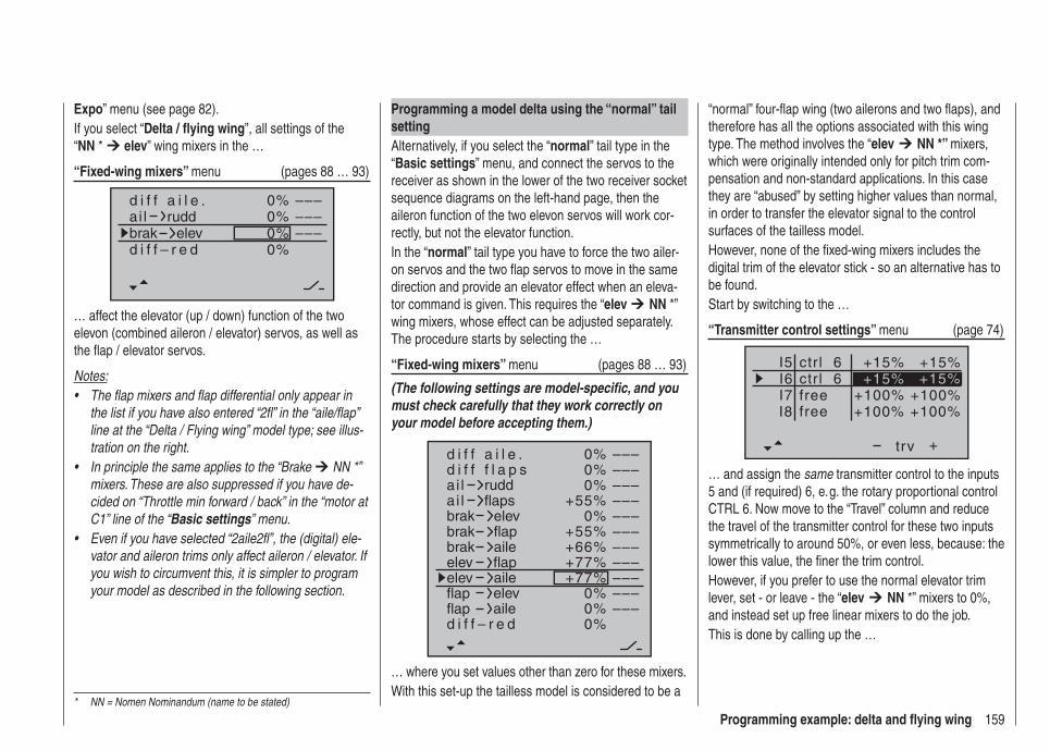
159Programming example: delta and fl ying wing
Programming a model delta using the “normal” tail settingAlternatively, if you select the “normal” tail type in the “Basic settings” menu, and connect the servos to the receiver as shown in the lower of the two receiver socket sequence diagrams on the left-hand page, then the aileron function of the two elevon servos will work cor-rectly, but not the elevator function.In the “normal” tail type you have to force the two ailer-on servos and the two fl ap servos to move in the same direction and provide an elevator effect when an eleva-tor command is given. This requires the “elev NN *” wing mixers, whose effect can be adjusted separately. The procedure starts by selecting the …
“Fixed-wing mixers” menu (pages 88 … 93)
(The following settings are model-specifi c, and you must check carefully that they work correctly on your model before accepting them.)
0%
0%0%
+55%0%
+55%+66%+77%+77%
0%0%0%
–––––––––––––––––––––––––––––––––
ai la i l
d i f f a i l e .
ruddflaps
brakbrakbrak
elevflapaile
elevelevflap
flapaileelev
flapd i f f – r e d
aile
d i f f f l a p s
… where you set values other than zero for these mixers.With this set-up the tailless model is considered to be a
Expo” menu (see page 82).If you select “Delta / fl ying wing”, all settings of the “NN * elev” wing mixers in the …
“Fixed-wing mixers” menu (pages 88 … 93)
0%
0%0%
–––––––––
0%
d i f f a i l e .ai l ruddbrak elevd i f f – r e d
… affect the elevator (up / down) function of the two elevon (combined aileron / elevator) servos, as well as the fl ap / elevator servos.
Notes:The flap mixers and flap differential only appear in • the list if you have also entered “2fl” in the “aile/flap” line at the “Delta / Flying wing” model type; see illus-tration on the right.In principle the same applies to the “Brake • NN *” mixers. These are also suppressed if you have de-cided on “Throttle min forward / back” in the “motor at C1” line of the “Basic settings” menu.Even if you have selected “2aile2fl”, the (digital) ele-• vator and aileron trims only affect aileron / elevator. If you wish to circumvent this, it is simpler to program your model as described in the following section.
“normal” four-fl ap wing (two ailerons and two fl aps), and therefore has all the options associated with this wing type. The method involves the “elev NN *” mixers, which were originally intended only for pitch trim com-pensation and non-standard applications. In this case they are “abused” by setting higher values than normal, in order to transfer the elevator signal to the control surfaces of the tailless model.However, none of the fi xed-wing mixers includes the digital trim of the elevator stick - so an alternative has to be found.Start by switching to the …
“Transmitter control settings” menu (page 74)
I5I6I7
+trv
+15% +15%
+100% +100%
ctrl 6
I8 +100% +100%freefree
ctr l 6 +15% +15%
… and assign the same transmitter control to the inputs 5 and (if required) 6, e. g. the rotary proportional control CTRL 6. Now move to the “Travel” column and reduce the travel of the transmitter control for these two inputs symmetrically to around 50%, or even less, because: the lower this value, the fi ner the trim control.However, if you prefer to use the normal elevator trim lever, set - or leave - the “elev NN *” mixers to 0%, and instead set up free linear mixers to do the job. This is done by calling up the …
* NN = Nomen Nominandum (name to be stated)

160 Programming example: delta and fl ying wing
“Free mixers” menu (pages 107 … 111)
typ fro to
M1M2M3
el 6el
??
5
??
trtr
… and setting up one linear mixer “Tr elev 5”, and - if necessary - “Tr elev 6”. Move to the graphic page of this menu to set the re-quired mixer ratios. Check the settings, and above all the direction of effect, in the “Servo display”, or on the model itself, and change the prefi xes if necessary.If you carry out the programming as described above, the ailerons will also move in the same direction, like fl aps, when you move the elevator stick. The effect of the “tr” option is that the elevator trim lever also affects the associated mixer when you operate the elevator stick.Since an additional transmitter control is no longer required for this arrangement, you should disable input 5 and (if used) input 6 in the second column of the “Trans-mitter control settings” menu; simply set these inputs to “free”.Many years ago, the author fl ew a model delta pro-grammed exactly in this way using the mc-20, with the following additional refi nements: “fl ap settings” used as trim, and butterfl y (crow) as landing aid - the latter exploiting the “Brake AIL” and “Brake FL” wing mixers to provide complete compensation for pitch trim changes in both directions. In this case the term “ailer-ons” means the outboard wing control surfaces, and “fl aps” the inboard pair of control surfaces.A modern sweptback fl ying wing can be controlled in
a similar fashion. These models also feature inboard and outboard control surfaces: the former forward of the Centre of Gravity, the latter aft of it. Defl ecting the inboard control surface(s) down increases lift and pro-duces an up-elevator effect; defl ecting them up creates the opposite effect. In contrast, the outboard ailerons act in the reverse direction: a down-defl ection produces a down-elevator effect, and vice versa. There are really no limits to what can be achieved with appropriate settings of the system’s sophisticated mixers.However, please note that you should be extremely careful when setting differential travel with such a con-fi guration, regardless of your model’s set-up, its tail type and the number of servos you are using. This is because differential travels on a tailless model tend to produce an asymmetrical elevator effect, rather than the desired adverse yaw reduction. For this reason it is advisable to start with a differential setting of 0% - at least for the fi rst few fl ights. When you are familiar with the model and feel the need to experiment, it may then be feasible under certain circumstances to try differential settings deviating from zero.For larger models it could be advisable to install winglets fi tted with rudders, i. e. small vertical surfaces at the wingtips. If these are actuated by two separate servos, they can be controlled as described in the example on page 157 dealing with “Servos running in parallel”, or using “Channel mapping” in the “Telemetry” menu; see page 121.You may also want both rudders to defl ect outwards when a braking system is operated using the Ch 1 stick, and this can be accomplished as follows: if you have selected the “normal” tail type, set up two further mixers “c1 4” and “c1 second rudder control channel”
with suitable travel settings. The offset for both mixers should be +100%, as the Ch 1 stick is usually at the forward end-point when the airbrakes are retracted, and the winglet rudders are only required to defl ect outwards proportionally when the brakes are extended.

161For your notes
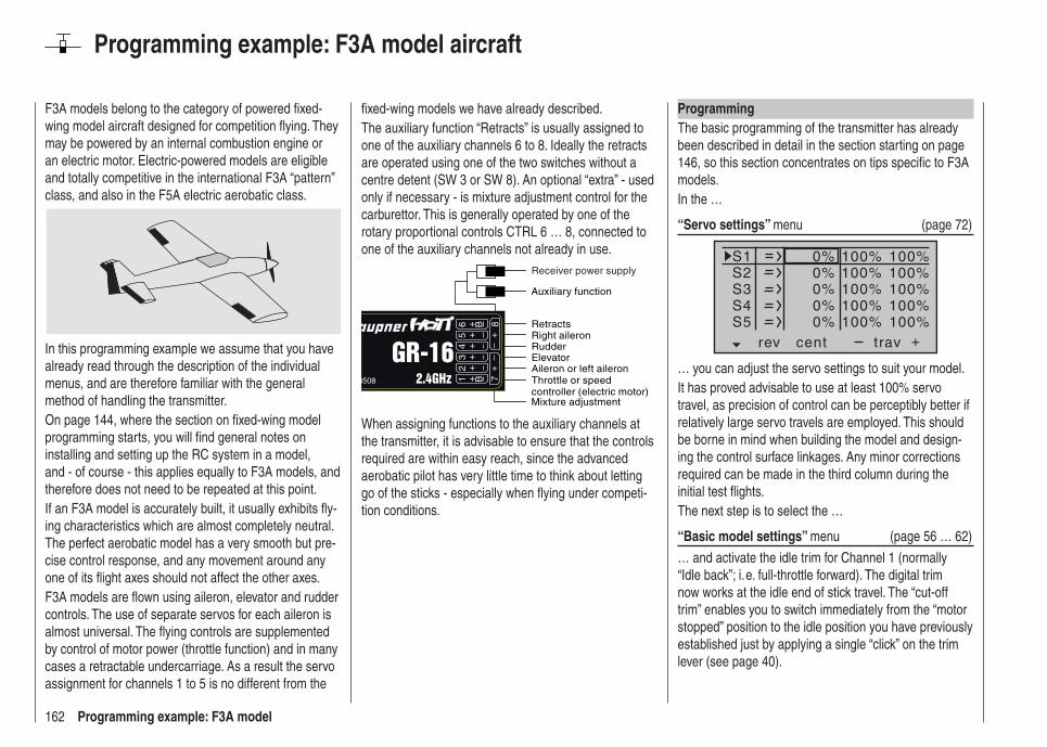
162 Programming example: F3A model
Programming example: F3A model aircraft
F3A models belong to the category of powered fi xed-wing model aircraft designed for competition fl ying. They may be powered by an internal combustion engine or an electric motor. Electric-powered models are eligible and totally competitive in the international F3A “pattern” class, and also in the F5A electric aerobatic class.
In this programming example we assume that you have already read through the description of the individual menus, and are therefore familiar with the general method of handling the transmitter.On page 144, where the section on fi xed-wing model programming starts, you will fi nd general notes on installing and setting up the RC system in a model, and - of course - this applies equally to F3A models, and therefore does not need to be repeated at this point.If an F3A model is accurately built, it usually exhibits fl y-ing characteristics which are almost completely neutral. The perfect aerobatic model has a very smooth but pre-cise control response, and any movement around any one of its fl ight axes should not affect the other axes.F3A models are fl own using aileron, elevator and rudder controls. The use of separate servos for each aileron is almost universal. The fl ying controls are supplemented by control of motor power (throttle function) and in many cases a retractable undercarriage. As a result the servo assignment for channels 1 to 5 is no different from the
fi xed-wing models we have already described.The auxiliary function “Retracts” is usually assigned to one of the auxiliary channels 6 to 8. Ideally the retracts are operated using one of the two switches without a centre detent (SW 3 or SW 8). An optional “extra” - used only if necessary - is mixture adjustment control for the carburettor. This is generally operated by one of the rotary proportional controls CTRL 6 … 8, connected to one of the auxiliary channels not already in use.
Throttle or speed controller (electric motor)Mixture adjustment
Retracts
Rudder
Aileron or left aileronElevator
Right aileron
Auxiliary function
Receiver power supply
When assigning functions to the auxiliary channels at the transmitter, it is advisable to ensure that the controls required are within easy reach, since the advanced aerobatic pilot has very little time to think about letting go of the sticks - especially when fl ying under competi-tion conditions.
ProgrammingThe basic programming of the transmitter has already been described in detail in the section starting on page 146, so this section concentrates on tips specifi c to F3A models.In the …
“Servo settings” menu (page 72)
S1S2S3
rev cent +trav
0%0%0%
100% 100%100% 100%100% 100%
0%0%
100% 100%100% 100%
S4S5
… you can adjust the servo settings to suit your model.It has proved advisable to use at least 100% servo travel, as precision of control can be perceptibly better if relatively large servo travels are employed. This should be borne in mind when building the model and design-ing the control surface linkages. Any minor corrections required can be made in the third column during the initial test fl ights.The next step is to select the …
“Basic model settings” menu (page 56 … 62)
… and activate the idle trim for Channel 1 (normally “Idle back”; i. e. full-throttle forward). The digital trim now works at the idle end of stick travel. The “cut-off trim” enables you to switch immediately from the “motor stopped” position to the idle position you have previously established just by applying a single “click” on the trim lever (see page 40).

163Programming example: F3A model
stick modemotor at C1
1
tail type normalcut off +150%–100% 9
aile/flap 2aile
idle re.
The remaining settings should be adjusted as required to suit your personal preferences.You may fi nd it necessary to assign transmitter controls to particular inputs to operate the retractable undercar-riage and carburettor mixture adjustment. This is carried out in the …
“Transmitter control settings” menu (page 74).
For example, you may like to assign a particular trans-mitter control - perhaps one of the ON / OFF switches SW 2 or 8 - to the input “E8” for the retracts, and a rotary proportional control - e. g. CTRL 6 - to the input “E7”, for mixture adjustment.
I5I6I7
+trv
I8ctr l 6freefree
8
+100% +100%+100%
+100% +100%+100% +100%
+100%
The retracts are extended and retracted when you oper-ate the switch “SW 8”. You may need to adjust the travel of the transmitter control, and perhaps reverse that channel by setting a negative prefi x for servo travel.F3A models fl y fairly fast, and respond very “solidly” to corrective movements of the servos. However, in com-petition fl ying it is vital that all abrupt control movements
model suddenly ballooning up.A little down-elevator must usually be mixed in to ensure that the aeroplane does not climb when the ailerons / fl aps are deployed.To meet these requirements you need the two mixers shown in the illustration below.
typ fro to
M1M2M3
c1 elc1
??
5
??
33
The mixers are activated using one and the same ex-ternal switch, e. g. “SW 3”, which therefore has to be as-signed to both mixers, with the same direction of effect.Touch the central SET button of the right-hand touch-key to move to the mixer inputs on the second screen page, and set the appropriate mixer ratios. In both cases the mixer neutral point should be left at the centre position of the Ch 1 stick travel.For this reason you should now move the Ch 1 stick to the Idle range, select the ASY fi eld, and enter the follow-ing values:MIX 1: -60% … -80% andMIX 2: -5% … -10%.
and corrections should be kept to a minimum, as the judges will invariably notice any lack of smoothness and dock a few points, so it is advisable to set exponential control characteristics on the stick functions.Move to the …
“D/R Expo” menu (page 82).
Exponential values of around +30% on aileron, elevator and rudder have proved to be a good starting point, and you can set them in the right-hand column of this menu. These values provide smooth, well-defi ned control of the typical F3A model. Many experts use higher values; even up to +60% exponential.
100%
100%100%
+33%+33%
aileelevrudd
DUAL EXPO
–––––––––+33%
Since F3A models generally have two aileron servos, it has proved useful to defl ect both ailerons “up” slightly for the landing. In most cases this causes the model to fl y a little more slowly and with a more stable attitude on the landing approach.To achieve this you will need to program mixers in the …
“Free mixers” menu (section starting on page 106).
Both ailerons are usually required to defl ect “up” as a landing aid, in parallel with the movement of the throttle stick, but only from the half-throttle setting in the direc-tion of idle. From that point on, the further the stick is moved towards the idle position, the more the ailerons defl ect up. The reverse occurs when you open the throttle: the ailerons are returned to neutral to avoid the
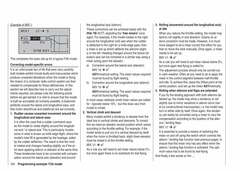
164 Programming example: F3A model
Example of MIX 1:
MIX1 c1 5
trv 0%0%offs
SYM ASY
–66%
This completes the basic set-up for a typical F3A model.
Correcting model-specifi c errorsIt is an unfortunate fact of life that even very carefully built models exhibit minute faults and inaccuracies which produce unwanted deviations when the model is fl ying; the mixers of a computer radio control system are then needed to compensate for these defi ciencies. In this section we will describe how to carry out the adjust-ments required, but please note the following points before we get started: it is vital to ensure that the model is built as accurately as humanly possible, is balanced perfectly around the lateral and longitudinal axes, and that motor downthrust and sidethrust are set correctly.
Rudder causes unwanted movement around the 1. longitudinal and lateral axesIt is often the case that a rudder command caus-es the model to rotate slightly around the longitudi-nal and / or lateral axis. This is particularly trouble-some in what is known as knife-edge fl ight, where the model’s total lift is generated by the fuselage, aided by the rudder defl ection. The result is that the mod-el rotates and changes heading slightly, as if the pi-lot were applying aileron or elevator at the same time. These tendencies have to be corrected with compen-sation around the lateral axis (elevator) and around
the longitudinal axis (aileron).These corrections can be achieved easily with the mx-16 HoTT, exploiting the “free mixers” once again. For example, if the model rotates to the right around the longitudinal (roll) axis when the rudder is defl ected to the right for a knife-edge pass, then a mixer is set up which defl ects the ailerons slight-ly to the left. Heading changes around the lateral (el-evator) axis can be corrected in a similar way using a mixer acting upon the elevator:a) Correction around the lateral axis (elevator) MIX “rd el”
ASYmmetrical setting. The exact values required must be found by fl ight testing.
b) Correction around the longitudinal axis (aileron)MIX “rd al”ASYmmetrical setting. The exact values required must be found by fl ight testing.
In most cases relatively small mixer values are called for - typically below 10% - but this does vary from model to model.Vertical climb and descent2. Many models exhibit a tendency to deviate from the ideal line in vertical climbs and descents. To correct this we need an elevator neutral position which varies according to the throttle setting. For example, if the model tends to pull out of a vertical descent by itself when the motor is throttled back, slight down-elevator must be mixed in at this throttle setting.MIX “c1 el” As a rule you will need to set mixer values below 5%, but once again there is no substitute for test-fl ying.
Rolling (movement around the longitudinal axis) 3. at idleWhen you reduce the throttle setting, the model may tend to roll slightly in one direction. Clearly an ai-leron correction must be made. However, it is much more elegant to let a mixer correct this effect for you than to move the stick manually. Once again, a mixer needs to be set up:MIX “c1 al” As a rule you will need to set mixer values below 5%, but once again test-fl ying is called for.The adjustment process should only be carried out in calm weather. Often all you need to do is apply the mixer in the control segment between half-throttle and idle. To achieve this, leave the Offset point at the centre position, and set up the mixer ASYmetrically. Rolling when ailerons and fl aps are extended4. If you fl y the landing approach with both ailerons de-fl ected up, the model may show a tendency to roll slightly due to minor variations in aileron servo trav-el (or constructional inaccuracies); i. e. the model may turn to either side by itself. Once again, this tenden-cy can easily be corrected using a mixer to vary the compensation according to the position of the ailer-ons / landing fl aps.MIX ”c1 al”It is essential to provide a means of switching the mixer on and off using the switch which controls the aileron / landing fl ap function (see previous page), to ensure that this mixer only has any effect when the aileron / landing fl ap function is activated. The opti-mum value has to be found by test-fl ying.
And fi nally a few words on the …
165Programming example: F3A model
“FAIL-SAFE settings”We strongly recommend that you make use of the safety potential of this option by at least setting the throttle position (glow-powered models) to idle, or the electric motor to stop, if a fail-safe event should be triggered. This simple precaution ensures that the model is much less likely to create havoc and cause property dam-age or personal injury. If you also program the fail-safe positions of the control surfaces in such a way that the model fl ies steadily descending circles in case of inter-ference, then you have a good chance that it will land relatively gently even if the radio link fails for a protracted period. This also gives you plenty of time to restore the connection, should the whole 2.4 GHz frequency band suffer interference for a while.In the receiver’s default state, however, the servos remain in their last valid position (“hold mode”) when in-terference occurs. You can program any individual servo output of your receiver to a “fail-safe position” (fail-safe mode), as described on page 116.
SummaryThe settings described on this page are intended primarily for the expert fl yer. Please bear in mind that refi ning the fl ying characteristics of a model aeroplane to this extent involves tremendous effort, time, sensitivity and expertise. Some experts continue the program-ming procedure even when they are fl ying, although it is not advisable to try this if you are just a moderately advanced pilot making your fi rst attempt with an F3A aerobatic model. You would be well advised to request help from an experienced pilot, and carry out the fi ne-tuning adjustments mentioned here one by one, with the expert at your side, until your model exhibits the neutral fl ying characteristics you desire.
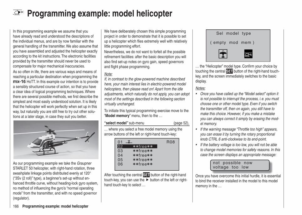
166 Programming example: model helicopter
Programming example: model helicopter
In this programming example we assume that you have already read and understood the descriptions of the individual menus, and are by now familiar with the general handling of the transmitter. We also assume that you have assembled and adjusted the helicopter exactly according to the kit instructions. The electronic facilities provided by the transmitter should never be used to compensate for major mechanical inaccuracies.As so often in life, there are various ways and means of reaching a particular destination when programming the mx-16 HoTT. In this example our intention is to provide a sensibly structured course of action, so that you have a clear idea of logical programming techniques. Where there are several possible methods, we fi rst describe the simplest and most easily understood solution. It is likely that the helicopter will work perfectly when set up in this way, but naturally you are still free to try out other solu-tions at a later stage, in case they suit you better.
As our programming example we take the Graupner STARLET 50 helicopter, with right-hand rotation, three swashplate linkage points distributed evenly at 120° (“3Sv (2 roll)” type), a beginner’s set-up without en-hanced throttle curve, without heading-lock gyro system, no method of infl uencing the gyro’s “normal operating mode” from the transmitter, and with no speed governor (regulator).
We have deliberately chosen this simple programming project in order to demonstrate that it is possible to set up a helicopter which fl ies extremely well with relatively little programming effort.Nevertheless, we do not want to forfeit all the possible refi nement facilities: after the basic description you will also fi nd set-up notes on gyro gain, speed governors and fl ight phase programming.
Note:If, in contrast to the glow-powered machine described here, your main interest lies in electric-powered model helicopters, then please read on! Apart from the idle adjustments, which naturally do not apply, you can adopt most of the settings described in the following section virtually unchanged.
To initiate this typical programming exercise move to the “Model memory” menu, then to the …
“select model” sub-menu (page 52),
… where you select a free model memory using the arrow buttons of the left or right-hand touch-key:
030405
free0201
06
R08
freefreefreefree
After touching the central SET button of the right-hand touch-key, you can use the button of the left or right-hand touch-key to select …
Sel model type
( empty mod mem )
… the “Helicopter” model type. Confi rm your choice by touching the central SET button of the right-hand touch-key, and the screen immediately switches to the basic display.
Notes:Once you have called up the “Model select” option it • is not possible to interrupt the process, i. e. you must choose one or other model type. Even if you switch the transmitter off, then on again, you still have to make this choice. However, if you make a mistake you can always correct it simply by erasing the mod-el memory.If the warning message “Throttle too high” appears, • you can erase it by turning the rotary proportional knob CTRL 6 anti-clockwise to its end-point.If the battery voltage is too low, you will not be able • to change model memories for safety reasons. In this case the screen displays an appropriate message:
not possible nowvoltage too low
Once you have overcome this initial hurdle, it is essential to bind the receiver installed in the model to this model memory in the …
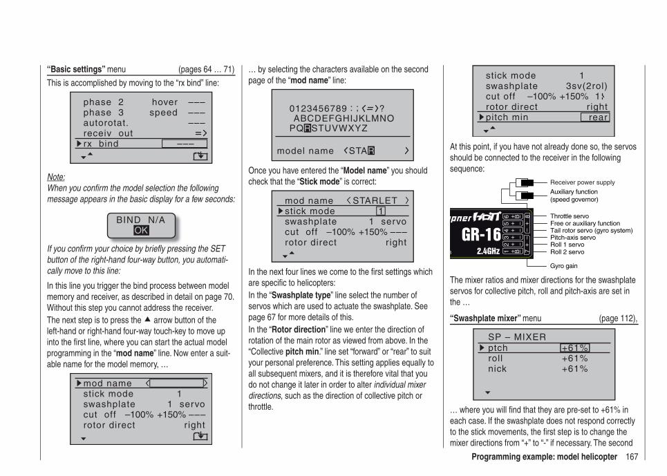
167Programming example: model helicopter
“Basic settings” menu (pages 64 … 71)
This is accomplished by moving to the “rx bind” line:
phase 3 speedautorotat.receiv outrx bind –––
phase 2 hover –––––––––
Note:When you confi rm the model selection the following message appears in the basic display for a few seconds:
BIND N/AOK
If you confi rm your choice by briefl y pressing the SET button of the right-hand four-way button, you automati-cally move to this line:
In this line you trigger the bind process between model memory and receiver, as described in detail on page 70. Without this step you cannot address the receiver.The next step is to press the arrow button of the left-hand or right-hand four-way touch-key to move up into the fi rst line, where you can start the actual model programming in the “mod name” line. Now enter a suit-able name for the model memory, …
mod namestick mode
rotor direct
swashplate1
right
1 servocut off –––+150%–100%
… by selecting the characters available on the second page of the “mod name” line:
0123456789
model name
?: ;ABCDEFGHIJKLMNO
STAR
PQRSTUVWXYZ
Once you have entered the “Model name” you should check that the “Stick mode” is correct:
mod namestick mode
rotor direct
swashplate1
right
1 servocut off –––+150%–100%
STARLET
In the next four lines we come to the fi rst settings which are specifi c to helicopters:In the “Swashplate type” line select the number of servos which are used to actuate the swashplate. See page 67 for more details of this.In the “Rotor direction” line we enter the direction of rotation of the main rotor as viewed from above. In the “Collective pitch min.” line set “forward” or “rear” to suit your personal preference. This setting applies equally to all subsequent mixers, and it is therefore vital that you do not change it later in order to alter individual mixer directions, such as the direction of collective pitch or throttle.
stick mode
rotor direct
swashplate1
right
3sv(2rol)cut off –100% +150% 1
pitch min rear
At this point, if you have not already done so, the servos should be connected to the receiver in the following sequence:
Roll 2 servo
Gyro gain
Throttle servo
Tail rotor servo (gyro system)
Roll 1 servoPitch-axis servo
Free or auxiliary function
Auxiliary function (speed governor)
Receiver power supply
The mixer ratios and mixer directions for the swashplate servos for collective pitch, roll and pitch-axis are set in the …
“Swashplate mixer” menu (page 112),
SP – MIXERptchrollnick
+61%+61%+61%
… where you will fi nd that they are pre-set to +61% in each case. If the swashplate does not respond correctly to the stick movements, the fi rst step is to change the mixer directions from “+” to “-” if necessary. The second
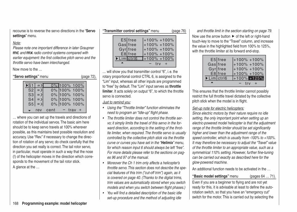
168 Programming example: model helicopter
“Transmitter control settings” menu (page 76)
+trv
free
freectr l6
E5GasGyrE8
Lim
+100%
+100% +100%+100% +100%
+100%+100% +100%+100% +100%
free
free
… will show you that transmitter control “6”, i. e. the rotary proportional control CTRL 6, is assigned to the “Lim” input, whereas all other inputs are programmed to “free” by default. The “Lim” input serves as throttle limiter. It acts solely on output “6”, to which the throttle servo is connected.
Just to remind you:Using the “Throttle limiter” function eliminates the • need to program an “Idle-up” fl ight phase.The throttle limiter does not control the throttle ser-• vo; it simply limits the travel of this servo in the for-ward direction, according to the setting of the throt-tle limiter, when required. The throttle servo is usually controlled by the collective pitch stick via the throttle curve or curves you have set in the “Helimix” menu, for which reason input 6 should always be left “free”. For more details please refer to the sections on pag-es 96 and 97 of the manual.Moreover the Ch 1 trim only affects a helicopter’s • throttle servo. This section does not describe the spe-cial features of this trim (“cut-off trim”) again, as it is covered on page 40. (Thanks to the digital trims, trim values are automatically stored when you switch models and when you switch between fl ight phases.)You will fi nd a detailed description of the basic idle • set-up procedure and the method of adjusting idle
recourse is to reverse the servo directions in the “Servo settings” menu.
Note:Please note one important difference in later Graupner mc and mx radio control systems compared with earlier equipment: the fi rst collective pitch servo and the throttle servo have been interchanged.
Now move to the …
“Servo settings” menu (page 72),
S1S2S3
rev cent +trav
0%0%0%
100% 100%100% 100%100% 100%
0%0%
100% 100%100% 100%
S4S5
… where you can set up the travels and directions of rotation of the individual servos. The basic aim here should be to keep servo travels at 100% wherever possible, as this maintains best possible resolution and accuracy. Use “Rev.” if necessary to change the direc-tion of rotation of any servo; do check carefully that the direction you set really is correct. The tail rotor servo, in particular, must operate in such a way that the nose (!) of the helicopter moves in the direction which corre-sponds to the movement of the tail rotor stick. A glance at the …
and throttle limit in the section starting on page 79.Now use the arrow button of the left or right-hand touch-key to move to the “Travel” column, and increase the value in the highlighted fi eld from 100% to 125%, with the throttle limiter at its forward end-stop.
+
+100%
+100% +100%+100% +100%
+100%+100% +100%+100% +125%
trv
free
freectr l6
E5GasGyrE8
Lim
free
free
This ensures that the throttle limiter cannot possibly restrict the full throttle travel dictated by the collective pitch stick when the model is in fl ight.
Set-up note for electric helicopters:Since electric motors by their nature require no idle setting, the only important point when setting up an electric-powered model helicopter is that the adjustment range of the throttle limiter should be set signifi cantly higher and lower than the adjustment range of the speed controller, which is usually from -100% to +100%. It may therefore be necessary to adjust the “Travel” value of the throttle limiter to an appropriate value, such as a symmetrical 110% setting. However, further fi ne-tuning can be carried out exactly as described here for the glow-powered machine.
An additional function needs to be activated in the …
“Basic model settings” menu (pages 64 … 71).
Even if you are a beginner to fl ying and are not yet ready for this, it is advisable at least to defi ne the auto-rotation switch, so that you have an “emergency cut” switch for the motor. This is carried out by selecting the
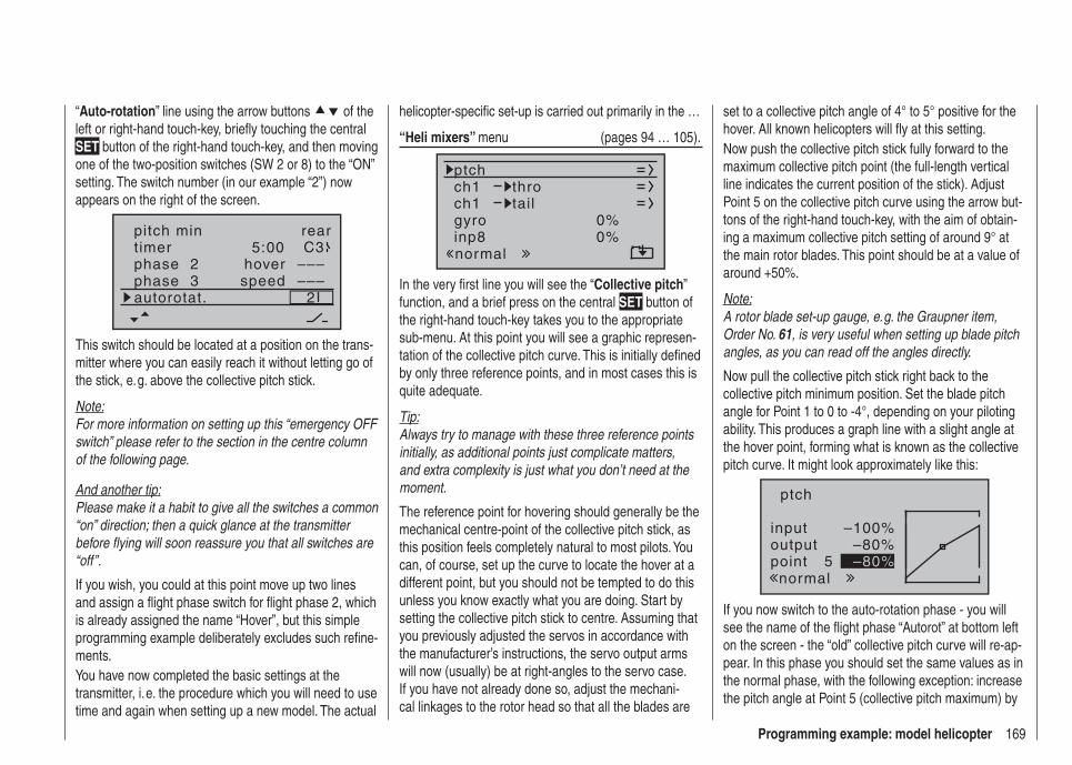
169Programming example: model helicopter
“Auto-rotation” line using the arrow buttons of the left or right-hand touch-key, briefl y touching the central SET button of the right-hand touch-key, and then moving one of the two-position switches (SW 2 or 8) to the “ON” setting. The switch number (in our example “2”) now appears on the right of the screen.
rear5:00 C3
2––––––phase 2
phase 3hoverspeed
pitch mintimer
autorotat.
This switch should be located at a position on the trans-mitter where you can easily reach it without letting go of the stick, e. g. above the collective pitch stick.
Note:For more information on setting up this “emergency OFF switch” please refer to the section in the centre column of the following page.
And another tip:Please make it a habit to give all the switches a common “on” direction; then a quick glance at the transmitter before fl ying will soon reassure you that all switches are “off”.
If you wish, you could at this point move up two lines and assign a fl ight phase switch for fl ight phase 2, which is already assigned the name “Hover”, but this simple programming example deliberately excludes such refi ne-ments.You have now completed the basic settings at the transmitter, i. e. the procedure which you will need to use time and again when setting up a new model. The actual
helicopter-specifi c set-up is carried out primarily in the …
“Heli mixers” menu (pages 94 … 105).
ch1ch1
ptchthrotail
normal
gyro 0%inp8 0%
In the very fi rst line you will see the “Collective pitch” function, and a brief press on the central SET button of the right-hand touch-key takes you to the appropriate sub-menu. At this point you will see a graphic represen-tation of the collective pitch curve. This is initially defi ned by only three reference points, and in most cases this is quite adequate.
Tip:Always try to manage with these three reference points initially, as additional points just complicate matters, and extra complexity is just what you don’t need at the moment.
The reference point for hovering should generally be the mechanical centre-point of the collective pitch stick, as this position feels completely natural to most pilots. You can, of course, set up the curve to locate the hover at a different point, but you should not be tempted to do this unless you know exactly what you are doing. Start by setting the collective pitch stick to centre. Assuming that you previously adjusted the servos in accordance with the manufacturer’s instructions, the servo output arms will now (usually) be at right-angles to the servo case. If you have not already done so, adjust the mechani-cal linkages to the rotor head so that all the blades are
set to a collective pitch angle of 4° to 5° positive for the hover. All known helicopters will fl y at this setting.Now push the collective pitch stick fully forward to the maximum collective pitch point (the full-length vertical line indicates the current position of the stick). Adjust Point 5 on the collective pitch curve using the arrow but-tons of the right-hand touch-key, with the aim of obtain-ing a maximum collective pitch setting of around 9° at the main rotor blades. This point should be at a value of around +50%.
Note:A rotor blade set-up gauge, e. g. the Graupner item, Order No. 61, is very useful when setting up blade pitch angles, as you can read off the angles directly.
Now pull the collective pitch stick right back to the collective pitch minimum position. Set the blade pitch angle for Point 1 to 0 to -4°, depending on your piloting ability. This produces a graph line with a slight angle at the hover point, forming what is known as the collective pitch curve. It might look approximately like this:
inputoutputpoint 5
–100%–80%–80%
ptch
normal
If you now switch to the auto-rotation phase - you will see the name of the fl ight phase “Autorot” at bottom left on the screen - the “old” collective pitch curve will re-ap-pear. In this phase you should set the same values as in the normal phase, with the following exception: increase the pitch angle at Point 5 (collective pitch maximum) by
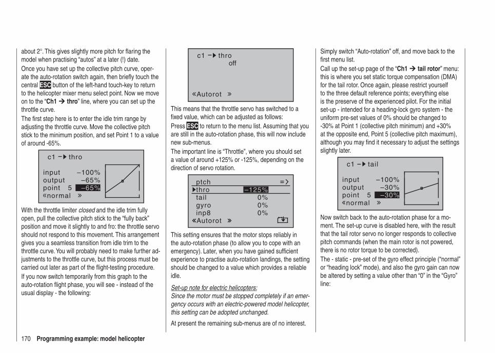
170 Programming example: model helicopter
about 2°. This gives slightly more pitch for fl aring the model when practising “autos” at a later (!) date.Once you have set up the collective pitch curve, oper-ate the auto-rotation switch again, then briefl y touch the central ESC button of the left-hand touch-key to return to the helicopter mixer menu select point. Now we move on to the “Ch1 thro” line, where you can set up the throttle curve.The fi rst step here is to enter the idle trim range by adjusting the throttle curve. Move the collective pitch stick to the minimum position, and set Point 1 to a value of around -65%.
inputoutputpoint 5
–100%–65%–65%
c1
normal
thro
With the throttle limiter closed and the idle trim fully open, pull the collective pitch stick to the “fully back” position and move it slightly to and fro: the throttle servo should not respond to this movement. This arrangement gives you a seamless transition from idle trim to the throttle curve. You will probably need to make further ad-justments to the throttle curve, but this process must be carried out later as part of the fl ight-testing procedure.If you now switch temporarily from this graph to the auto-rotation fl ight phase, you will see - instead of the usual display - the following:
c1
Autorot
throoff
This means that the throttle servo has switched to a fi xed value, which can be adjusted as follows:Press ESC to return to the menu list. Assuming that you are still in the auto-rotation phase, this will now include new sub-menus.The important line is “Throttle”, where you should set a value of around +125% or -125%, depending on the direction of servo rotation.
tail
ptchthro
Autorot
gyro 0%inp8 0%
0%–125%
This setting ensures that the motor stops reliably in the auto-rotation phase (to allow you to cope with an emergency). Later, when you have gained suffi cient experience to practise auto-rotation landings, the setting should be changed to a value which provides a reliable idle.
Set-up note for electric helicopters:Since the motor must be stopped completely if an emer-gency occurs with an electric-powered model helicopter, this setting can be adopted unchanged.
At present the remaining sub-menus are of no interest.
Simply switch “Auto-rotation” off, and move back to the fi rst menu list.Call up the set-up page of the “Ch1 tail rotor” menu: this is where you set static torque compensation (DMA) for the tail rotor. Once again, please restrict yourself to the three default reference points; everything else is the preserve of the experienced pilot. For the initial set-up - intended for a heading-lock gyro system - the uniform pre-set values of 0% should be changed to -30% at Point 1 (collective pitch minimum) and +30% at the opposite end, Point 5 (collective pitch maximum), although you may fi nd it necessary to adjust the settings slightly later.
inputoutputpoint 5
–100%–30%–30%
c1
normal
tail
Now switch back to the auto-rotation phase for a mo-ment. The set-up curve is disabled here, with the result that the tail rotor servo no longer responds to collective pitch commands (when the main rotor is not powered, there is no rotor torque to be corrected).The - static - pre-set of the gyro effect principle (“normal” or “heading lock” mode), and also the gyro gain can now be altered by setting a value other than “0” in the “Gyro” line:
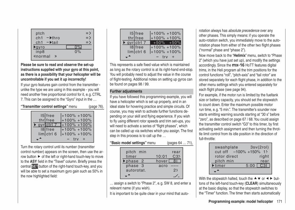
171Programming example: model helicopter
ch1ch1
ptchthrotail
normal
gyro 0%inp8 0%
Please be sure to read and observe the set-up instructions supplied with your gyro at this point, as there is a possibility that your helicopter will be uncontrollable if you set it up incorrectly!If your gyro features gain control from the transmitter - unlike the type we are using in this example - you will need another free proportional control for it, e. g. CTRL 7. This can be assigned to the “Gyro” input in the …
“Transmitter control settings” menu (page 76).
+trv
free
freectr l 6
ctr l 7
I5thrgyr
I8lim
+100% +100%+100% +100%+100% +100%+100% +100%+100% +100%
free
Turn the rotary control until its number (transmitter control number) appears on the screen, then use the ar-row button of the left or right-hand touch-key to move to the ASY fi eld in the “Travel” column. Briefl y press the central SET button of the right-hand touch-key, and you will be able to set a maximum gyro gain such as 50% in the now highlighted fi eld:
+
+100% +100%+100% +100%
+100% +100%+100% +100%
+50% +50%
trv
free
freectr l 6
ctr l 7
I5thrgyr
I8lim
free
This represents a safe fi xed value which is maintained as long as the rotary control is at its right-hand end-stop. You will probably need to adjust the value in the course of fl ight-testing. Additional notes on setting up gyros can be found on pages 98 / 99.
Further adjustmentsIf you have followed this programming example, you will have a helicopter which is set up properly, and in an ideal state for hovering practice and simple circuits. Of course, you may wish to activate further functions de-pending on your skill and fl ying experience. If you wish to fl y using different rotor speeds and trim set-ups, you will need to activate a series of “fl ight phases”, which can be called up via switches which you assign. The fi rst step in this process is to call up the …
“Basic model settings” menu (pages 64 … 71),
pitch min reartimer 10:01 C3phase 2phase 3
hoveracro
autorotat. 2–––
8
… assign a switch to “Phase 2”, e. g. SW 8, and enter a relevant name (if you wish).It is important to be quite clear in your mind that auto-
rotation always has absolute precedence over any other phases. This simply means: if you operate the auto-rotation switch, you immediately move to the auto-rotation phase from either of the other two fl ight phases (“normal” phase and “phase 2”).Now move back to the “Helimix” menu, switch to “Phase 2” (which you have just set up), and modify the settings accordingly. Since the mx-16 HoTT features digital trims, in the Heli program all the trim positions for the control functions “roll”, “pitch-axis” and “tail rotor” are stored separately for each fl ight phase, in addition to the other menu settings which you entered separately for each fl ight phase (see page 94).For example, if the motor run is limited by the fueltank size or battery capacity, you should set the stopwatch to count down. Enter the maximum possible motor run time, e. g. “5 min.”. The transmitter’s sounder now starts emitting warning sounds starting at “30 s” before “zero”, as described on page 67 / 68. You could assign the transmitter control switch “G3” to this timer, by fi rst activating switch assignment and then turning the throt-tle limit control from its idle position in the direction of full-throttle:
rotor direct
swashplate
right
3sv(2rol)cut off –100% +150% 1
pitch min reartimer 5:00 C3
With the stopwatch halted, touch the or but-tons of the left-hand touch-key (CLEAR) simultaneously at the basic display, so that the stopwatch switches to the “Timer” function. The timer then starts automatically
172 Programming example: model helicopter
when you move the throttle limit slider towards full-throttle, and stops again when you move the limiter back to the idle range.
Suggested refi nement: speed governorAt some time you may wish to install a speed governor (regulator) in your helicopter, e. g. the mc-Heli-Control, to try fl ying with a system rotational speed which is automatically maintained at a constant value. It makes sense to couple the individual rotor speeds with the fl ight phases, as this enables you to carry out further fi ne-tuning.The initial requirement when programming the transmit-ter is to install and program the speed governor exactly in accordance with the manufacturer’s instructions. Of course, the mx-16 HoTT provides further facilities to allow you to implement different rotational speeds in the individual fl ight phases. A practical suggestion, which includes the throttle limiter function, can be found in the section starting on page 97.
If you have set up your helicopter as described in this programming example, you will fi nd that it is capable of carrying out extremely challenging fl ight tasks even though it is not suitable for competition work. We suggest that you should not make use of additional functions until your model is fl ying perfectly, so that you will be in a position to recognise and appreciate any improvements. Whenever possible, it is always best to implement additional refi nements one at a time, other-wise you won’t know which change has brought about any improvement. Bear in mind that the good pilot is not recognised by the number of complex functions with which he can cope, but by the results he can obtain when fl ying a relatively simple set-up.

173For your notes
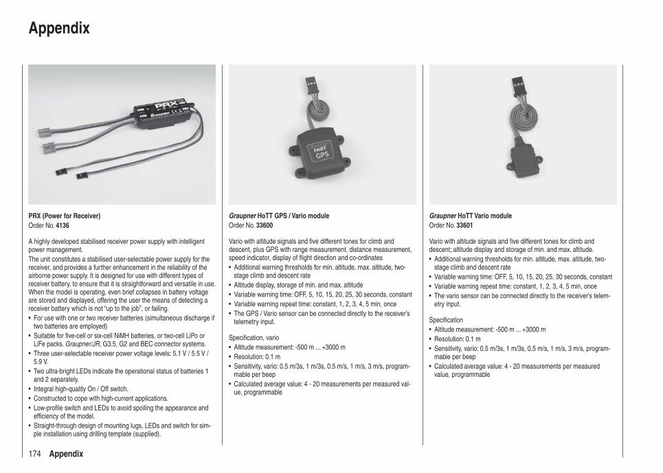
174 Appendix
PRX (Power for Receiver)Order No. 4136
A highly developed stabilised receiver power supply with intelligent power management.The unit constitutes a stabilised user-selectable power supply for the receiver, and provides a further enhancement in the reliability of the airborne power supply. It is designed for use with different types of receiver battery, to ensure that it is straightforward and versatile in use. When the model is operating, even brief collapses in battery voltage are stored and displayed, offering the user the means of detecting a receiver battery which is not “up to the job”, or failing.
For use with one or two receiver batteries (simultaneous discharge if • two batteries are employed)Suitable for fi ve-cell or six-cell NiMH batteries, or two-cell LiPo or • LiFe packs. Graupner/JR, G3.5, G2 and BEC connector systems.Three user-selectable receiver power voltage levels: 5.1 V / 5.5 V / • 5.9 V.Two ultra-bright LEDs indicate the operational status of batteries 1 • and 2 separately.Integral high-quality On / Off switch.• Constructed to cope with high-current applications.• Low-profi le switch and LEDs to avoid spoiling the appearance and • effi ciency of the model.Straight-through design of mounting lugs, LEDs and switch for sim-• ple installation using drilling template (supplied).
Appendix
Graupner HoTT Vario moduleOrder No. 33601
Vario with altitude signals and fi ve different tones for climb and descent; altitude display and storage of min. and max. altitude.
Additional warning thresholds for min. altitude, max. altitude, two-• stage climb and descent rateVariable warning time: OFF, 5, 10, 15, 20, 25, 30 seconds, constant• Variable warning repeat time: constant, 1, 2, 3, 4, 5 min, once• The vario sensor can be connected directly to the receiver’s telem-• etry input.
Specifi cationAltitude measurement: -500 m ... +3000 m• Resolution: 0.1 m• Sensitivity, vario: 0.5 m/3s, 1 m/3s, 0.5 m/s, 1 m/s, 3 m/s, program-• mable per beepCalculated average value: 4 - 20 measurements per measured • value, programmable
Graupner HoTT GPS / Vario moduleOrder No. 33600
Vario with altitude signals and fi ve different tones for climb and descent, plus GPS with range measurement, distance measurement, speed indicator, display of fl ight direction and co-ordinates
Additional warning thresholds for min. altitude, max. altitude, two-• stage climb and descent rateAltitude display, storage of min. and max. altitude• Variable warning time: OFF, 5, 10, 15, 20, 25, 30 seconds, constant• Variable warning repeat time: constant, 1, 2, 3, 4, 5 min, once• The GPS / Vario sensor can be connected directly to the receiver’s • telemetry input.
Specifi cation, varioAltitude measurement: -500 m ... +3000 m• Resolution: 0.1 m• Sensitivity, vario: 0.5 m/3s, 1 m/3s, 0.5 m/s, 1 m/s, 3 m/s, program-• mable per beepCalculated average value: 4 - 20 measurements per measured val-• ue, programmable
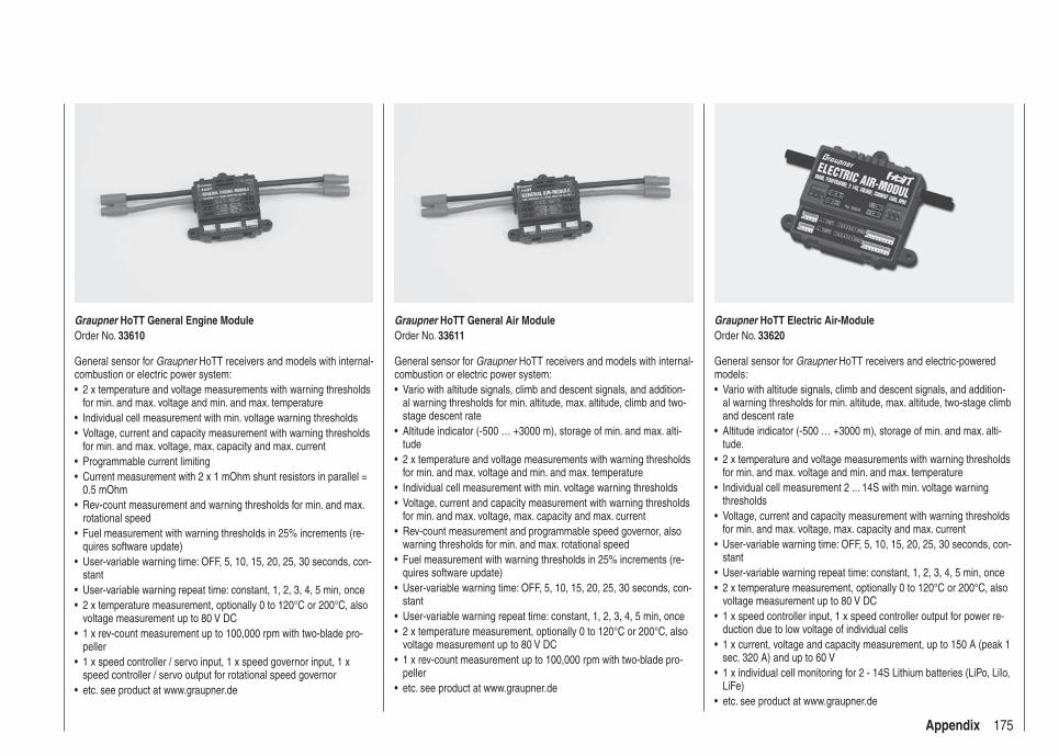
175Appendix
Graupner HoTT General Engine ModuleOrder No. 33610
General sensor for Graupner HoTT receivers and models with internal-combustion or electric power system:
2 x temperature and voltage measurements with warning thresholds • for min. and max. voltage and min. and max. temperatureIndividual cell measurement with min. voltage warning thresholds• Voltage, current and capacity measurement with warning thresholds • for min. and max. voltage, max. capacity and max. currentProgrammable current limiting• Current measurement with 2 x 1 mOhm shunt resistors in parallel = • 0.5 mOhmRev-count measurement and warning thresholds for min. and max. • rotational speedFuel measurement with warning thresholds in 25% increments (re-• quires software update)User-variable warning time: OFF, 5, 10, 15, 20, 25, 30 seconds, con-• stantUser-variable warning repeat time: constant, 1, 2, 3, 4, 5 min, once• 2 x temperature measurement, optionally 0 to 120°C or 200°C, also • voltage measurement up to 80 V DC1 x rev-count measurement up to 100,000 rpm with two-blade pro-• peller1 x speed controller / servo input, 1 x speed governor input, 1 x • speed controller / servo output for rotational speed governoretc. see product at www.graupner.de•
Graupner HoTT General Air ModuleOrder No. 33611
General sensor for Graupner HoTT receivers and models with internal-combustion or electric power system:
Vario with altitude signals, climb and descent signals, and addition-• al warning thresholds for min. altitude, max. altitude, climb and two-stage descent rateAltitude indicator (-500 … +3000 m), storage of min. and max. alti-• tude2 x temperature and voltage measurements with warning thresholds • for min. and max. voltage and min. and max. temperatureIndividual cell measurement with min. voltage warning thresholds• Voltage, current and capacity measurement with warning thresholds • for min. and max. voltage, max. capacity and max. currentRev-count measurement and programmable speed governor, also • warning thresholds for min. and max. rotational speedFuel measurement with warning thresholds in 25% increments (re-• quires software update)User-variable warning time: OFF, 5, 10, 15, 20, 25, 30 seconds, con-• stantUser-variable warning repeat time: constant, 1, 2, 3, 4, 5 min, once• 2 x temperature measurement, optionally 0 to 120°C or 200°C, also • voltage measurement up to 80 V DC1 x rev-count measurement up to 100,000 rpm with two-blade pro-• pelleretc. see product at www.graupner.de•
Graupner HoTT Electric Air-ModuleOrder No. 33620
General sensor for Graupner HoTT receivers and electric-powered models:
Vario with altitude signals, climb and descent signals, and addition-• al warning thresholds for min. altitude, max. altitude, two-stage climb and descent rateAltitude indicator (-500 … +3000 m), storage of min. and max. alti-• tude.2 x temperature and voltage measurements with warning thresholds • for min. and max. voltage and min. and max. temperatureIndividual cell measurement 2 ... 14S with min. voltage warning • thresholdsVoltage, current and capacity measurement with warning thresholds • for min. and max. voltage, max. capacity and max. currentUser-variable warning time: OFF, 5, 10, 15, 20, 25, 30 seconds, con-• stantUser-variable warning repeat time: constant, 1, 2, 3, 4, 5 min, once• 2 x temperature measurement, optionally 0 to 120°C or 200°C, also • voltage measurement up to 80 V DC1 x speed controller input, 1 x speed controller output for power re-• duction due to low voltage of individual cells1 x current, voltage and capacity measurement, up to 150 A (peak 1 • sec. 320 A) and up to 60 V1 x individual cell monitoring for 2 - 14S Lithium batteries (LiPo, LiIo, • LiFe)etc. see product at www.graupner.de•
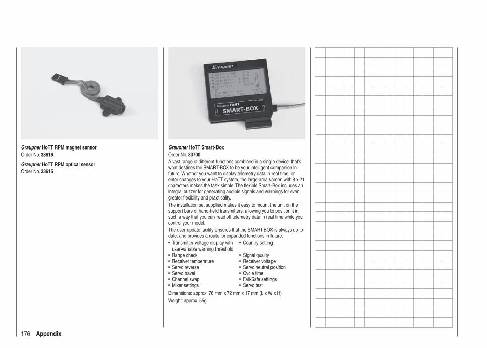
176 Appendix
Graupner HoTT Smart-BoxOrder No. 33700A vast range of different functions combined in a single device: that’s what destines the SMART-BOX to be your intelligent companion in future. Whether you want to display telemetry data in real time, or enter changes to your HoTT system, the large-area screen with 8 x 21 characters makes the task simple. The fl exible Smart-Box includes an integral buzzer for generating audible signals and warnings for even greater fl exibility and practicality.The installation set supplied makes it easy to mount the unit on the support bars of hand-held transmitters, allowing you to position it in such a way that you can read off telemetry data in real time while you control your model.The user-update facility ensures that the SMART-BOX is always up-to-date, and provides a route for expanded functions in future.
Transmitter voltage display with • user-variable warning threshold
Country setting•
Range check• Signal quality• Receiver temperature• Receiver voltage• Servo reverse• Servo neutral position• Servo travel• Cycle time• Channel swap• Fail-Safe settings• Mixer settings• Servo test•
Dimensions: approx. 76 mm x 72 mm x 17 mm (L x W x H)Weight: approx. 55g
Graupner HoTT RPM magnet sensorOrder No. 33616
Graupner HoTT RPM optical sensorOrder No. 33615

177Conformity declaration
Conformity declaration
Ko
nfo
rmit
ätse
rklä
run
g g
emäß
dem
Ges
etz
üb
er F
un
kan
lag
en u
nd
Tele
kom
un
ikat
ion
sen
dei
nri
chtu
ng
en (
FT
EG
) u
nd
der
Ric
htl
inie
199
9/5/
EG
(R
&T
TE
)D
ecla
ratio
n of
Con
form
ity i
n ac
cord
ianc
e w
ith t
he R
adio
and
Tel
ecom
unik
atio
ns T
erm
inal
Equ
ipm
ent
Act
(F
TE
G)
and
Dire
ctiv
e 19
99/5
/EG
(R
&T
TE
)
Gra
upne
r Gm
bH &
Co.
KG
Hen
riette
nstra
ße 9
4-96
D-7
3230
Kirc
hhei
m/T
eck
erkl
ärt,
dass
das
Pro
dukt
:de
clar
es th
at th
e pr
oduc
t
Ger
ätek
lass
e:2
Equ
ipm
ent c
lass
den
grun
dleg
ende
n A
nfor
deru
ngen
des
§ 3
und
den
übr
igen
eins
chlä
gige
n B
estim
mun
gen
des
FT
EG
(A
rtik
el 3
der
R&
TT
E)
ents
pric
ht.
com
plie
s w
ith th
e es
sent
ial r
equi
rem
ents
of §
3 a
nd th
e ot
her
rele
vant
pro
visi
ons
of th
e F
TE
G (
Art
icle
3 o
f the
R&
TT
E D
irect
ive)
.
Ang
ewen
dete
har
mon
isie
rte
Nor
men
:H
arm
onis
ed s
tand
ards
app
lied
EN
609
50:2
006
EN
301
489
-1
V1.
7.1
EN
301
489
-3
V1.
4.1
EN
300
328
V1.
7.1
H
ealth
and
saf
ety
requ
irem
ents
pur
suan
t to
§ 3
(1)
1. (
Art
icle
3 (
1) a
))
P
rote
ctio
n re
quire
men
t con
cern
ig e
lect
rom
agne
tic c
ompa
tibili
ty
§
3 (1
) 2,
Art
ikel
3 (
1) b
))
M
easu
res
for
the
effic
ient
use
of t
he r
adio
freq
uenc
y sp
ectr
um
§
3 (2
) (A
rtic
le 3
(2)
)
Kirc
hhei
m, 0
9. M
ärz
2011
S
tefa
n G
raup
ner,
Ges
chäf
tsfü
hrer
S
tefa
n G
raup
ner,
Man
agin
g D
irect
or
Gra
up
ner
Gm
bH
& C
o.
KG
Hen
riet
ten
stra
ße
94-9
6 D
-732
30 K
irch
hei
m/T
eck
Ger
man
yT
el:
0702
1/72
2-0
EM
ail:
in
fo@
gra
up
ner
.de
Fax
: 07
021/
722-
188
Ges
undh
eit u
nd S
iche
rhei
t gem
äß §
3 (
1) 1
. (A
rtik
el 3
(1)
a))
Sch
utza
nfor
deru
ngen
in B
ezug
auf
ele
ktro
mag
netis
che
V
ertr
äglic
hkei
t § 3
(1)
2, A
rtik
el 3
(1)
b))
Maß
nahm
en z
ur e
ffizi
ente
n N
utzu
ng d
es F
requ
enzs
pekt
rum
s §
3 (2
) (A
rtik
el 3
(2)
)
mx-
12 H
oT
T -
No
. 331
12, m
x-16
Ho
TT
- N
o. 3
3116
,m
x-20
Ho
TT
- N
o. 3
3124
,G
R-1
2 H
oT
T -
No
. 335
06, G
R-1
6 H
oT
T -
No
. 335
08,
GR
-24
Ho
TT
- N
o. 3
3512
178 FCC Information
FCC Information
Graupner mx-16 HoTT #33116
FCC ID: ZGZ-mx-16-20
FCC Label Compliance StatementThis device complies with Part 15 of the FCC Rules. Operation is subject to the following two conditions:
This device may not cause harmful interference.1. This device must accept any interference received, 2. including interference that may cause undesired op-eration.
WARNING:Changes or modifi cations not expressly approved by the party responsible for compliance could void the user‘s authority to operate the equipment.
NOTEThis equipment has been tested and found to comply with the limits for a Class B digital device, pursuant to Part 15 of the FCC Rules. These limits are designed to provide reasonable protection against harmful interfer-ence in a residential installation. This equipment gener-ates uses and can radiate radio frequency energy and, if not installed and used in accordance with the instruc-tions, may cause harmful interference to radio communi-cations. However, there is no guarantee that interference will not occur in a particular installation. If this equipment does cause harmful interference to radio or television reception, which can be determined by turning the equipment off and on, the user is encouraged to try to correct the interference by one or more of the following measures:
Reorient or relocate the receiving antenna.• Increase the separation between the equipment and • receiver.
Connect the equipment into an outlet on a circuit dif-• ferent from that to which the receiver is connected.Consult the dealer or an experienced radio/TV tech-• nician for help.
RF Exposure StatementThis device has been evaluated to meet the FCC RF exposure requirement when used in combination with the genuine Graupner HoTT accessoires and operated with a minimum distance of 20 cm between the antenna and your body.

179Guarantee certifi cate
Wir gewähren auf dieses Erzeugnis eine Garantie von This product is warrantied for
Sur ce produit nous accordons une garantie de 24 MonatenmonthsmoisGuarantee certifi cate
Servicestellen / Service / Service après-venteGraupner-ZentralserviceGraupner GmbH & Co. KGHenriettenstrasse 94 - 96D-73230 Kirchheim
Servicehotline (+49) 0 18 05 47 28 76*
Montag - Freitag9:30-11:30 + 13:00-15:00 Uhr
United KingdomGraupner ServiceBrunel DriveGB, NEWARK, Nottingham-shireNG242EG
(+44) 16 36 61 05 39
SverigeBaltechno ElectronicsBox 5307S 40227 Göteborg
(+46) 31 70 73 00 0
SchweizGraupner ServiceWehntalerstrasse 37CH 8181 Höri
(+41) 43 26 66 58 3
LuxembourgKit Flammang129, route d’ArlonL 8009 Strassen
(+35) 23 12 23 2
FranceGraupner FranceGérard Altmayer86, rue St. AntoineF 57601 Forbach-Oeting
(+33) 3 87 85 62 12
EspanaAnguera Hobbies C/Terrassa 14 E 43206 Reus (Tarragona).
(+34) 97 77 55 32 0 [email protected]
Ceská RepublikaSlovenská RepublikaRC Service Z. HnizdilLetecka 666/22CZ 16100 Praha 6 - Ruzyne
(+42) 2 33 31 30 95
Belgie/Belgique/NederlandJan van MouwerikSlot de Houvelaan 30NL 3155 Maasland VT
(+31) 10 59 13 59 4
ItaliaGiMaxVia Manzoni, no. 8I 25064 Gussago
(+39) 030 25 22 73 2
* 0,14 Cent / Minute aus dem Festnetz der deutschen T-Com. Abweichende Preise für Anrufe aus Mobilfunknet-zen oder aus dem Festnetz anderer Anbieter möglich.
Die Fa. Graupner GmbH & Co. KG, Henriettenstraße 94 - 96, D-73230 Kirchheim/Teck gewährt ab dem Kaufdatum auf dieses Produkt eine Garantie von 24 Monaten. Die Garantie gilt nur für die bereits beim Kauf des Produktes vorhandenen Material- oder Funktionsmängel. Schäden, die auf Abnützung, Überlastung, falsches Zubehör oder unsachgemäße Behand-lung zurückzuführen sind, sind von der Garantie ausgeschlos-sen. Die gesetzlichen Rechte und Gewährleistunsansprüche des Verbrauchers werden durch diese Garantie nicht berührt. Bitte überprüfen Sie vor einer Reklamation oder Rücksendung das Produkt genau auf Mängel, da wir Ihnen bei Mängelfreiheit die entstandenen Unkosten in Rechnung stellen müssen.
Graupner GmbH & Co. KG, Henriettenstraße 94 - 96. D-73230 Kirchheim/Teck, Germany guarantees this product for a period of 24 months from date of purchase. The guarantee applies only to such material or operational defects witch are present at the time of purchase of the product. Damage due to wear, overloading, incompetent handling or the use of incorrect accessories is not covered by the guarantee. The user´s legal rights and claims under guarantee are not affected by this guarantee. Please check the product carefully for defects be-fore you are make a claim or send the item to us, since we are obliged to make a charge for our cost if the product is found to be free of faults.
La société Graupner GmbH & Co. KG, Henriettenstraße 94-96, D-73230 Kirchheim/Teck, accorde sur ce produit une garantie de 24 mois à compter de la date d’achat. La garantie ne s’applique qu’aux défauts de matériel et de fonctionnement du produit acheté. Les dommages dus à une usure, à une surcharge, à l’emploi d’accessoires non compatibles ou à une manipulation non conforme sont exclus de la garantie. Cette garantie ne remet pas en cause les droits légaux des consom-mateurs. Avant toute réclamation ou retour de matériel, vérifi ez précisément les défauts ou vices constatés, car si le matériel est conforme et qu’aucun défaut n’a été constaté par nos services, nous nous verrions contraints de facturer le coût de cette intervention.
Garantie-UrkundeWarranty certifi cate / Certifi cat de garantie
mx-16 HoTT Set
Order No. 33116
Übergabedatum:Date of purchase/delivery:Date d’achat :
Name des Käufers:Owner´s name:Nom de I`acheteur :
Straße, Wohnort:Complete address:Adresse complète :
Firmenstempel und Unterschrift des Einzelhändlers:Stamp and signature of dealer:Cachet et signature du détaillant :

H O P P I N G . T E L E M E T R Y . T R A N S M I S S I O N
GRAUPNER GMBH & CO. KGPOSTFACH 1242D-73220 KIRCHHEIM/TECKGERMANY
http://www.graupner.de
Modifi cations and availability reserved. Graupner products are only available through model shops. We will gladly inform you of your nearest stockist. We accept no liability for printing errors.
Printed in Germany PN.PE-02
Although we have carefully checked the information contained in these instructions and checked that it is correct, we can accept no liability of any kind for mistakes, incomplete information and printing errors. Graupner reserves the right to alter the characteristics and features of the software and hardware at any time and without prior notifi cation.