mvi56 mcm rev 2 user manual - prosoft technology inc manual: detailed reference guide to the module,...
TRANSCRIPT
MVI56E-MCMR ControlLogix Platform Enhanced Modbus Master/Slave Communications Module with Reduced Data Block
June 29, 2010
SETUP GUIDE
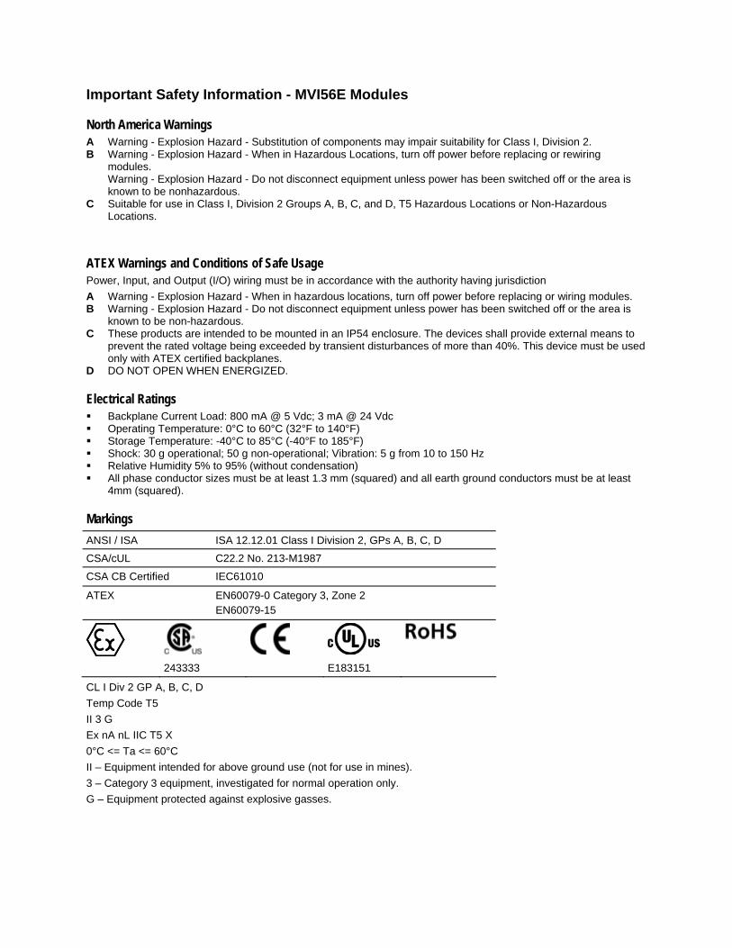
Important Safety Information - MVI56E Modules
North America Warnings A Warning - Explosion Hazard - Substitution of components may impair suitability for Class I, Division 2. B Warning - Explosion Hazard - When in Hazardous Locations, turn off power before replacing or rewiring
modules. Warning - Explosion Hazard - Do not disconnect equipment unless power has been switched off or the area is known to be nonhazardous.
C Suitable for use in Class I, Division 2 Groups A, B, C, and D, T5 Hazardous Locations or Non-Hazardous Locations.
ATEX Warnings and Conditions of Safe Usage Power, Input, and Output (I/O) wiring must be in accordance with the authority having jurisdiction A Warning - Explosion Hazard - When in hazardous locations, turn off power before replacing or wiring modules. B Warning - Explosion Hazard - Do not disconnect equipment unless power has been switched off or the area is
known to be non-hazardous. C These products are intended to be mounted in an IP54 enclosure. The devices shall provide external means to
prevent the rated voltage being exceeded by transient disturbances of more than 40%. This device must be used only with ATEX certified backplanes.
D DO NOT OPEN WHEN ENERGIZED.
Electrical Ratings Backplane Current Load: 800 mA @ 5 Vdc; 3 mA @ 24 Vdc Operating Temperature: 0°C to 60°C (32°F to 140°F) Storage Temperature: -40°C to 85°C (-40°F to 185°F) Shock: 30 g operational; 50 g non-operational; Vibration: 5 g from 10 to 150 Hz Relative Humidity 5% to 95% (without condensation) All phase conductor sizes must be at least 1.3 mm (squared) and all earth ground conductors must be at least
4mm (squared).
Markings
ANSI / ISA ISA 12.12.01 Class I Division 2, GPs A, B, C, D
CSA/cUL C22.2 No. 213-M1987
CSA CB Certified IEC61010
ATEX EN60079-0 Category 3, Zone 2 EN60079-15
243333 E183151
CL I Div 2 GP A, B, C, D Temp Code T5 II 3 G Ex nA nL IIC T5 X 0°C <= Ta <= 60°C II – Equipment intended for above ground use (not for use in mines). 3 – Category 3 equipment, investigated for normal operation only. G – Equipment protected against explosive gasses.
Battery Life Advisory The module uses a rechargeable Lithium Vanadium Pentoxide battery to backup the real-time clock and CMOS settings. The battery itself should last for the life of the module. However, if left in an unpowered state for 14 to 21 days, the battery may become fully discharged and require recharging by being placed in a powered-up ControlLogix chassis. The time required to fully recharge the battery may be as long as 24 hours. Once it is fully charged, the battery provides backup power for the CMOS setup and the real-time clock for approximately 21 days. Before you remove a module from its power source, ensure that the battery within the module is fully charged (the BATT LED on the front of the module goes OFF when the battery is fully charged). If the battery is allowed to become fully discharged, the module will revert to the default BIOS and clock settings.
Note: The battery is not user-replaceable or serviceable.
ProSoft Technology® Product Documentation In an effort to conserve paper, ProSoft Technology no longer includes printed manuals with our product shipments. User Manuals, Datasheets, Sample Ladder Files, and Configuration Files are provided on the enclosed CD-ROM, and are available at no charge from our web site: www.prosoft-technology.com Printed documentation is available for purchase. Contact ProSoft Technology for pricing and availability. North America: +1.661.716.5100 Asia Pacific: +603.7724.2080 Europe, Middle East, Africa: +33 (0) 5.3436.87.20 Latin America: +1.281.298.9109

Your Feedback Please We always want you to feel that you made the right decision to use our products. If you have suggestions, comments, compliments or complaints about our products, documentation, or support, please write or call us.
ProSoft Technology 5201 Truxtun Ave., 3rd Floor Bakersfield, CA 93309 +1 (661) 716-5100 +1 (661) 716-5101 (Fax) www.prosoft-technology.com [email protected] Copyright © 2010 ProSoft Technology, Inc., all rights reserved. MVI56E-MCMR Setup Guide 6/23/2010 ProSoft Technology ®, ProLinx ®, inRAx ®, ProTalk®, and RadioLinx ® are Registered Trademarks of ProSoft Technology, Inc. All other brand or product names are or may be trademarks of, and are used to identify products and services of, their respective owners.
MVI56E-MCMR ♦ ControlLogix Platform Contents Enhanced Modbus Master/Slave Communications Module with Reduced Data Block Setup Guide
ProSoft Technology, Inc. Page 5 of 74 June 29, 2010
Contents Important Safety Information - MVI56E Modules................................................................................2 Battery Life Advisory ...........................................................................................................................3 ProSoft Technology® Product Documentation....................................................................................3 Your Feedback Please........................................................................................................................4
1 Scope 7 1.1 What’s New? .............................................................................................................7 1.2 Learning Objectives...................................................................................................8 1.3 ProSoft Technology Documentation .........................................................................9 1.4 Prerequisites ...........................................................................................................10
2 Before You Begin 11 2.1 System Requirements .............................................................................................11 2.2 Required Items ........................................................................................................12 2.3 Sample Files............................................................................................................13
3 Install the Configuration Tools 15 3.1 Install ProSoft Discovery Service ............................................................................15
4 The Sample Application 17 4.1 About the MODBUS Protocol..................................................................................17 4.2 General Overview....................................................................................................18
4.2.1 Required Steps........................................................................................................19 4.3 Architecture .............................................................................................................20 4.4 Memory Map ...........................................................................................................21
5 Procedures 23 5.1 Physical Setup.........................................................................................................23
5.1.1 Set Module Jumpers ...............................................................................................23 5.1.2 Install the Module in the Remote Rack ...................................................................24 5.1.3 Connect Your PC to the Module's Ethernet Port.....................................................25 5.1.4 Set Temporary IP Address......................................................................................26 5.1.5 Connect to the Module's Web Page........................................................................34 5.1.6 Upload the Add-On Instruction from the Module.....................................................36
5.2 Connect your PC to the ControlLogix Processor ....................................................46 5.3 Download the Sample Program to the Processor...................................................47 5.4 Using ProSoft Configuration Builder Software ........................................................48
5.4.1 Upload the Sample Configuration from the Module ................................................48 5.4.2 Enable the Port 1 Master Commands .....................................................................51
5.5 Download the Project to the Module .......................................................................54 5.6 Configure the Quantum Processor as a Modbus Slave..........................................56 5.7 Connect the MVI56E-MCMR Module to the Quantum Processor ..........................57 5.8 Verify Communication .............................................................................................58
Contents MVI56E-MCMR ♦ ControlLogix Platform Setup Guide Enhanced Modbus Master/Slave Communications Module with Reduced Data Block
Page 6 of 74 ProSoft Technology, Inc. June 29, 2010
5.8.1 View Exchanged Data ............................................................................................ 58 5.8.2 Check Module Status through ControlLogix Controller Tags ................................. 61 5.8.3 Scrolling LED Status Indicators .............................................................................. 63 5.8.4 Ethernet LED Indicators.......................................................................................... 64 5.8.5 Non-Scrolling LED Status Indicators ...................................................................... 64
6 Building on Success 65 6.1 Frequently Asked Questions................................................................................... 66
6.1.1 What are the differences between the MVI56 and the MVI56E modules? What does the “E” stand for?................................................................................................................ 66 6.1.2 Is the MVI56E product a direct replacement to my existing MVI56 product?......... 66 6.1.3 How is the MVI56E-MCMR configured?................................................................. 66 6.1.4 What is ProSoft Configuration Builder (PCB)? ....................................................... 67 6.1.5 What is the purpose of the MVI56E-MCMR Ethernet (E1) Port? ........................... 67 6.1.6 How do I change the module’s IP address? ........................................................... 67 6.1.7 Does the MVI56E-MCMR module require processor logic?................................... 67 6.1.8 What is the purpose of the Optional MVI56E-MCMR Add-On Instruction?............ 68 6.1.9 What is ProSoft Discovery Service (PDS)? ............................................................ 68 6.1.10 How do I monitor MVI56E-MCMR operation? ........................................................ 68 6.1.11 Are there any other ways to monitor module diagnostics besides being connected to the module’s network (subnet)? .............................................................................................. 68
7 Glossary of Terms 69
Index 73
MVI56E-MCMR ♦ ControlLogix Platform Scope Enhanced Modbus Master/Slave Communications Module with Reduced Data Block Setup Guide
ProSoft Technology, Inc. Page 7 of 74 June 29, 2010
1 Scope
In This Chapter
What’s New? ...........................................................................................7
Learning Objectives.................................................................................8
ProSoft Technology Documentation........................................................9
Prerequisites .........................................................................................10
This document acts as a tutorial in providing step-by-step instructions on how to read and write bi-directional data from one network device to another network device using the MVI56E-MCMR module.
1.1 What’s New? MVI56E products are backward compatible with existing MVI56 ladder logic and module configuration files. You can easily swap and replace products while benefiting from an array of new features designed to improve interoperability and enhance the user experience. WEB Page: Use a standard web browser to access the module’s web page
through the new Ethernet port ProSoft Discovery Service (PDS): Allows ProSoft Configuration software
and/or separate optional software to find and display a list of all MVI56E modules on the network, and to temporarily change IP addresses to connect with the module web page
ProSoft Configuration Builder (PCB): New Windows-style graphical user interface (GUI) for configuration and diagnostics with improved graphical screen navigation. Connect via Ethernet port or CIPconnect® to upload/download module configuration information
CIPconnect®-enabled: Allows PC-to-module configuration and diagnostics via 1756-ENBT local and remote chassis from anywhere on the Ethernet network using PCB
Personality Card: A compact flash memory card storing the module’s settings, for quick and easy replacement of modules in the field
LED Scrolling Diagnostic Display: 4-character, alpha-numeric display, providing English messages for status and alarm data, and for processor and network communication conditions
Scope MVI56E-MCMR ♦ ControlLogix Platform Setup Guide Enhanced Modbus Master/Slave Communications Module with Reduced Data Block
Page 8 of 74 ProSoft Technology, Inc. June 29, 2010
1.2 Learning Objectives When you have completed all the steps in this Setup Guide, you will have learned how to Use the sample application (page 17) Install the MVI56E-MCMR setup and diagnostic software (page 15) Install the MVI56E-MCMR module (page 23) Import the Add-On Instruction to the processor (page 47) Configure the Modbus Master (page 51) using the sample Add-On Instruction Configure the Modbus Slave (page 56) Verify the MVI56E-MCMR module communication status (page 58)
MVI56E-MCMR ♦ ControlLogix Platform Scope Enhanced Modbus Master/Slave Communications Module with Reduced Data Block Setup Guide
ProSoft Technology, Inc. Page 9 of 74 June 29, 2010
1.3 ProSoft Technology Documentation ProSoft Technology provides the following documentation (manuals) with your MVI56E-MCMR. Electronic documentation (on the MVI56E-MCMR web page) Setup Guide: (this manual) Describes the sample application, and takes
you through the steps necessary to install, configure, and verify the correct operation of the module
User Manual: Detailed reference guide to the module, protocol configuration, functional overview, diagnostics and troubleshooting procedures, and product specifications
Datasheet: Brief description of the module hardware and protocol implementation, general and functional specifications
Additional documentation, tools, and product support Email Technical Support: Send your support questions to Support@prosoft-
technology.com Web Site Support: Visit the ProSoft Technology web site at
www.prosoft-technology.com to download additional documentation, tools and application information
Telephone Support: Please call ProSoft Technology Technical Support at: (Country Code 1+) 661-716-5100. Support is available 24 hours a day, 7 days a week. ProSoft Technology telephone support is free and unlimited
Scope MVI56E-MCMR ♦ ControlLogix Platform Setup Guide Enhanced Modbus Master/Slave Communications Module with Reduced Data Block
Page 10 of 74 ProSoft Technology, Inc. June 29, 2010
1.4 Prerequisites To get the most benefit from this Setup Guide, you should have the following skills: Rockwell Automation® RSLogix™ 5000 software: launch the program,
configure, and transfer the Add-On Instruction (or ladder logic) Sample Application program to the processor
Microsoft Windows®: install and launch programs, execute menu commands, navigate dialog boxes and enter data.
Serial data communication: correctly configure data communication parameters such as baud rate, parity, data bits, and so on, using the documentation for the devices connected to the network
Ethernet networking: connect the MVI56E-MCMR module to an Ethernet network using a valid IP address and subnet mask
Hardware installation and wiring: install the module and safely connect Modbus Master/Slave and ControlLogix devices to a power source and to the MVI56E-MCMR module’s serial ports
MVI56E-MCMR ♦ ControlLogix Platform Before You Begin Enhanced Modbus Master/Slave Communications Module with Reduced Data Block Setup Guide
ProSoft Technology, Inc. Page 11 of 74 June 29, 2010
2 Before You Begin
In This Chapter
System Requirements ...........................................................................11
Required Items ......................................................................................12
Sample Files..........................................................................................13
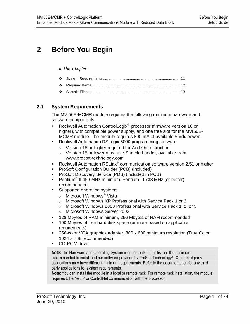
2.1 System Requirements The MVI56E-MCMR module requires the following minimum hardware and software components: Rockwell Automation ControlLogix® processor (firmware version 10 or
higher), with compatible power supply, and one free slot for the MVI56E-MCMR module. The module requires 800 mA of available 5 Vdc power
Rockwell Automation RSLogix 5000 programming software o Version 16 or higher required for Add-On Instruction o Version 15 or lower must use Sample Ladder, available from
www.prosoft-technology.com Rockwell Automation RSLinx® communication software version 2.51 or higher ProSoft Configuration Builder (PCB) (included) ProSoft Discovery Service (PDS) (included in PCB) Pentium® II 450 MHz minimum. Pentium III 733 MHz (or better)
recommended Supported operating systems:
o Microsoft Windows® Vista o Microsoft Windows XP Professional with Service Pack 1 or 2 o Microsoft Windows 2000 Professional with Service Pack 1, 2, or 3 o Microsoft Windows Server 2003
128 Mbytes of RAM minimum, 256 Mbytes of RAM recommended 100 Mbytes of free hard disk space (or more based on application
requirements) 256-color VGA graphics adapter, 800 x 600 minimum resolution (True Color
1024 × 768 recommended) CD-ROM drive
Note: The Hardware and Operating System requirements in this list are the minimum recommended to install and run software provided by ProSoft Technology®. Other third party applications may have different minimum requirements. Refer to the documentation for any third party applications for system requirements. Note: You can install the module in a local or remote rack. For remote rack installation, the module requires EtherNet/IP or ControlNet communication with the processor.
Before You Begin MVI56E-MCMR ♦ ControlLogix Platform Setup Guide Enhanced Modbus Master/Slave Communications Module with Reduced Data Block
Page 12 of 74 ProSoft Technology, Inc. June 29, 2010
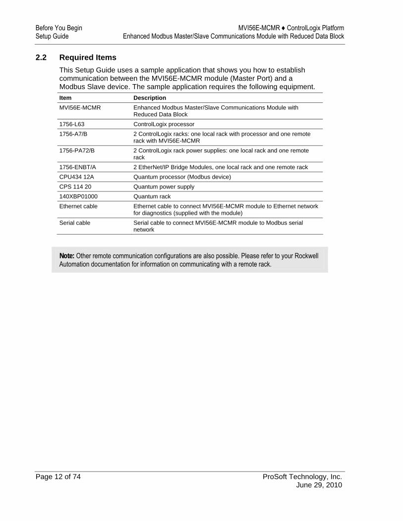
2.2 Required Items This Setup Guide uses a sample application that shows you how to establish communication between the MVI56E-MCMR module (Master Port) and a Modbus Slave device. The sample application requires the following equipment. Item Description MVI56E-MCMR Enhanced Modbus Master/Slave Communications Module with
Reduced Data Block 1756-L63 ControlLogix processor 1756-A7/B 2 ControlLogix racks: one local rack with processor and one remote
rack with MVI56E-MCMR 1756-PA72/B 2 ControlLogix rack power supplies: one local rack and one remote
rack 1756-ENBT/A 2 EtherNet/IP Bridge Modules, one local rack and one remote rack CPU434 12A Quantum processor (Modbus device) CPS 114 20 Quantum power supply 140XBP01000 Quantum rack Ethernet cable Ethernet cable to connect MVI56E-MCMR module to Ethernet network
for diagnostics (supplied with the module) Serial cable Serial cable to connect MVI56E-MCMR module to Modbus serial
network
Note: Other remote communication configurations are also possible. Please refer to your Rockwell Automation documentation for information on communicating with a remote rack.
MVI56E-MCMR ♦ ControlLogix Platform Before You Begin Enhanced Modbus Master/Slave Communications Module with Reduced Data Block Setup Guide
ProSoft Technology, Inc. Page 13 of 74 June 29, 2010
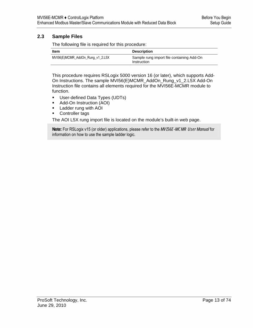
2.3 Sample Files The following file is required for this procedure: Item Description MVI56(E)MCMR_AddOn_Rung_v1_2.L5X Sample rung import file containing Add-On
Instruction
This procedure requires RSLogix 5000 version 16 (or later), which supports Add-On Instructions. The sample MVI56(E)MCMR_AddOn_Rung_v1_2.L5X Add-On Instruction file contains all elements required for the MVI56E-MCMR module to function. User-defined Data Types (UDTs) Add-On Instruction (AOI) Ladder rung with AOI Controller tags
The AOI L5X rung import file is located on the module’s built-in web page.
Note: For RSLogix v15 (or older) applications, please refer to the MVI56E-MCMR User Manual for information on how to use the sample ladder logic.

Before You Begin MVI56E-MCMR ♦ ControlLogix Platform Setup Guide Enhanced Modbus Master/Slave Communications Module with Reduced Data Block
Page 14 of 74 ProSoft Technology, Inc. June 29, 2010
MVI56E-MCMR ♦ ControlLogix Platform Install the Configuration Tools Enhanced Modbus Master/Slave Communications Module with Reduced Data Block Setup Guide
ProSoft Technology, Inc. Page 15 of 74 June 29, 2010
3 Install the Configuration Tools
In This Chapter
Install ProSoft Discovery Service ..........................................................15
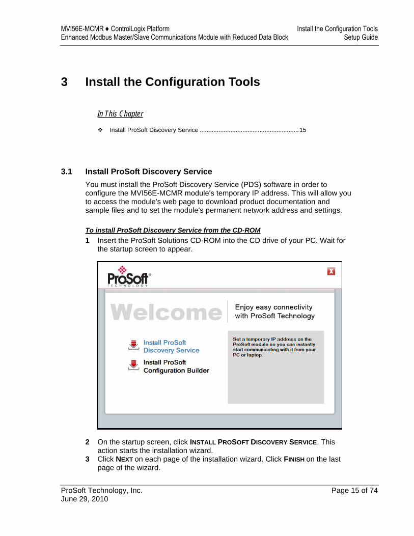
3.1 Install ProSoft Discovery Service You must install the ProSoft Discovery Service (PDS) software in order to configure the MVI56E-MCMR module's temporary IP address. This will allow you to access the module's web page to download product documentation and sample files and to set the module's permanent network address and settings. To install ProSoft Discovery Service from the CD-ROM 1 Insert the ProSoft Solutions CD-ROM into the CD drive of your PC. Wait for
the startup screen to appear.
2 On the startup screen, click INSTALL PROSOFT DISCOVERY SERVICE. This action starts the installation wizard.
3 Click NEXT on each page of the installation wizard. Click FINISH on the last page of the wizard.

Install the Configuration Tools MVI56E-MCMR ♦ ControlLogix Platform Setup Guide Enhanced Modbus Master/Slave Communications Module with Reduced Data Block
Page 16 of 74 ProSoft Technology, Inc. June 29, 2010
MVI56E-MCMR ♦ ControlLogix Platform The Sample Application Enhanced Modbus Master/Slave Communications Module with Reduced Data Block Setup Guide
ProSoft Technology, Inc. Page 17 of 74 June 29, 2010
4 The Sample Application
In This Chapter
About the MODBUS Protocol ................................................................17
General Overview..................................................................................18
Architecture ...........................................................................................20
Memory Map .........................................................................................21
4.1 About the MODBUS Protocol MODBUS is a widely-used protocol originally developed by Modicon in 1978. Since that time, the protocol has been adopted as a standard throughout the automation industry. The original MODBUS specification uses a serial connection to communicate commands and data between Master and Slave devices on a network. Later enhancements to the protocol allow communication over other types of networks. MODBUS is a Master/Slave protocol. The Master establishes a connection to the remote Slave. When the connection is established, the Master sends the MODBUS commands to the Slave. The MVI56E-MCMR module can work as a Master and as a Slave. The MVI56E-MCMR module also works as an input/output module between itself and the Rockwell Automation backplane and processor. The module uses an internal database to pass data and commands between the processor and Master and Slave devices on MODBUS networks.
The Sample Application MVI56E-MCMR ♦ ControlLogix Platform Setup Guide Enhanced Modbus Master/Slave Communications Module with Reduced Data Block
Page 18 of 74 ProSoft Technology, Inc. June 29, 2010
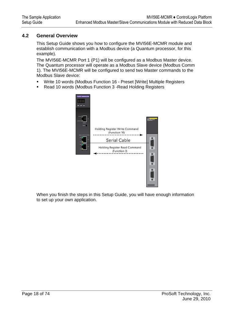
4.2 General Overview This Setup Guide shows you how to configure the MVI56E-MCMR module and establish communication with a Modbus device (a Quantum processor, for this example). The MVI56E-MCMR Port 1 (P1) will be configured as a Modbus Master device. The Quantum processor will operate as a Modbus Slave device (Modbus Comm 1). The MVI56E-MCMR will be configured to send two Master commands to the Modbus Slave device: Write 10 words (Modbus Function 16 - Preset [Write] Multiple Registers Read 10 words (Modbus Function 3 -Read Holding Registers
When you finish the steps in this Setup Guide, you will have enough information to set up your own application.
MVI56E-MCMR ♦ ControlLogix Platform The Sample Application Enhanced Modbus Master/Slave Communications Module with Reduced Data Block Setup Guide
ProSoft Technology, Inc. Page 19 of 74 June 29, 2010
4.2.1 Required Steps This Setup Guide will take you through the following steps: 1 Install the ProSoft Module in the rack (page 23) 2 Use the Add-On Instruction to Configure the Module (page 37) 3 Connect your PC to the Processor (page 46) 4 Download the Sample Program to the Processor (page 47) 5 Set up the Read and Write Database Areas
a Configure Modbus Port 1 (P1) b Configure the Modbus Master Read Command (page 52, page 53) c Configure the Modbus Master Write Command
6 Reboot the module 7 Set up the Quantum Processor Modbus Slave Port (page 56) 8 Verify Communication (page 58)
The Sample Application MVI56E-MCMR ♦ ControlLogix Platform Setup Guide Enhanced Modbus Master/Slave Communications Module with Reduced Data Block
Page 20 of 74 ProSoft Technology, Inc. June 29, 2010
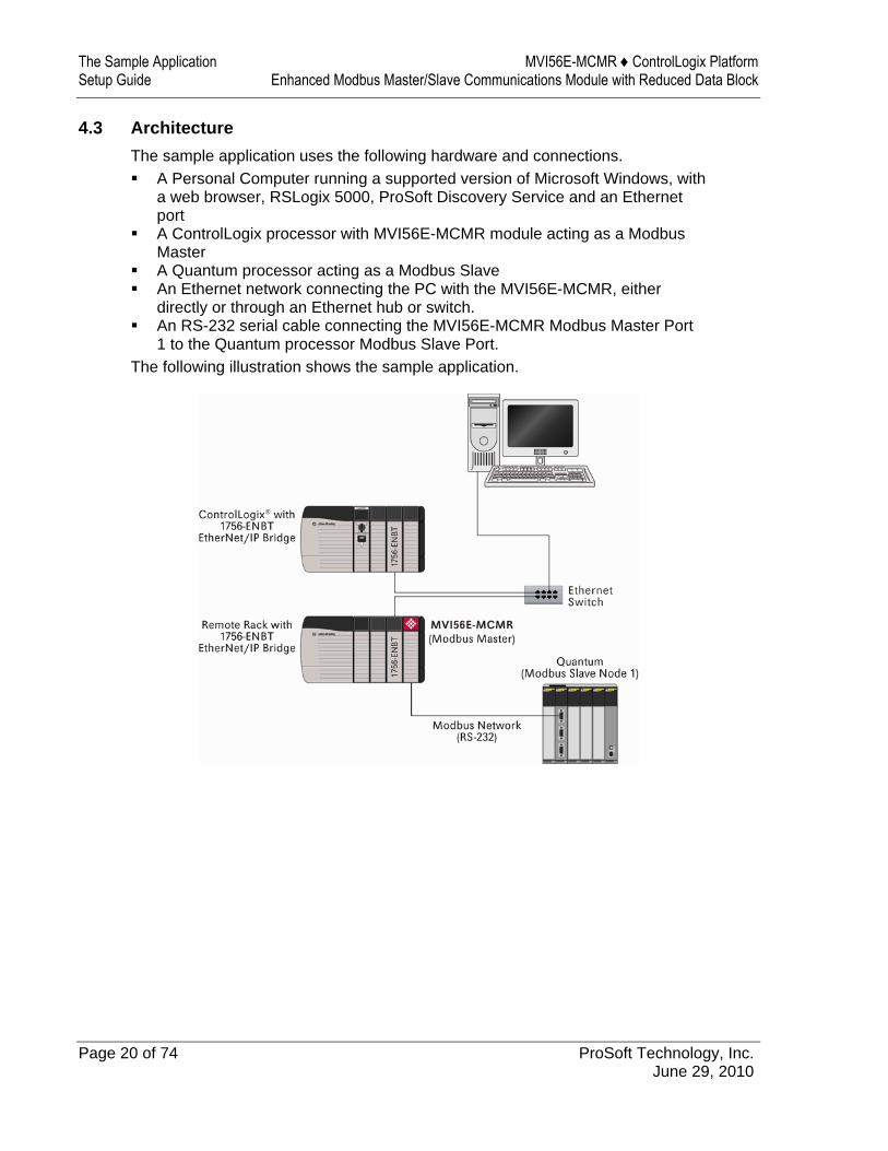
4.3 Architecture The sample application uses the following hardware and connections. A Personal Computer running a supported version of Microsoft Windows, with
a web browser, RSLogix 5000, ProSoft Discovery Service and an Ethernet port
A ControlLogix processor with MVI56E-MCMR module acting as a Modbus Master
A Quantum processor acting as a Modbus Slave An Ethernet network connecting the PC with the MVI56E-MCMR, either
directly or through an Ethernet hub or switch. An RS-232 serial cable connecting the MVI56E-MCMR Modbus Master Port
1 to the Quantum processor Modbus Slave Port. The following illustration shows the sample application.

MVI56E-MCMR ♦ ControlLogix Platform The Sample Application Enhanced Modbus Master/Slave Communications Module with Reduced Data Block Setup Guide
ProSoft Technology, Inc. Page 21 of 74 June 29, 2010
4.4 Memory Map The memory map consists of the starting addresses for Read Data and Write Data areas in the MVI56E-MCMR module and in the Quantum processor. The sample application reads and writes 10 words between the Modbus Master and the Modbus Slave. The following table describes the memory map for data transfer between the MVI56E-MCMR module and the Quantum processor. Function MVI56E-MCMR Database
Start Address (Master) Quantum Memory Start Address (Slave)
Word Count
Read 1000 400801 10 Write 0 400401 10

The Sample Application MVI56E-MCMR ♦ ControlLogix Platform Setup Guide Enhanced Modbus Master/Slave Communications Module with Reduced Data Block
Page 22 of 74 ProSoft Technology, Inc. June 29, 2010
MVI56E-MCMR ♦ ControlLogix Platform Procedures Enhanced Modbus Master/Slave Communications Module with Reduced Data Block Setup Guide
ProSoft Technology, Inc. Page 23 of 74 June 29, 2010
5 Procedures
In This Chapter
Physical Setup.......................................................................................23
Connect your PC to the ControlLogix Processor ...................................46
Download the Sample Program to the Processor..................................47
Using ProSoft Configuration Builder Software.......................................48
Download the Project to the Module......................................................54
Configure the Quantum Processor as a Modbus Slave.........................56
Connect the MVI56E-MCMR Module to the Quantum Processor..........57
Verify Communication ...........................................................................58
5.1 Physical Setup
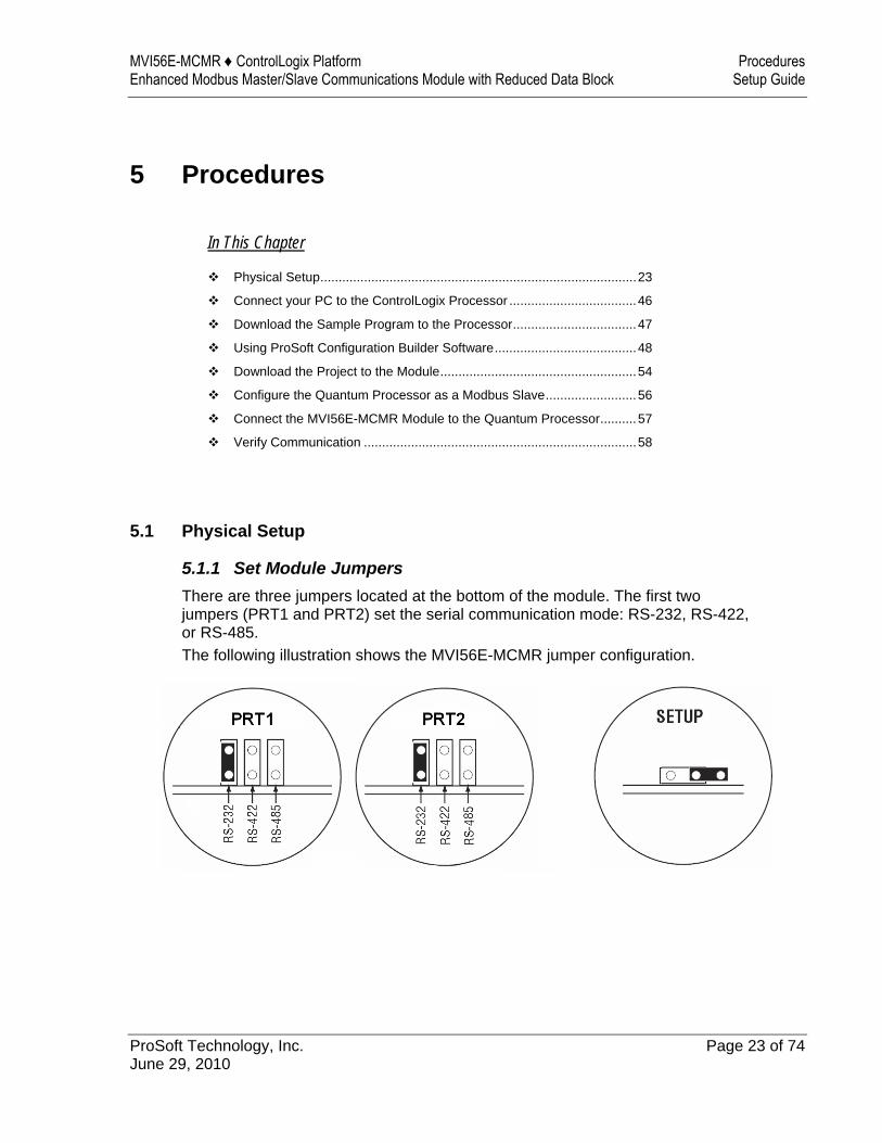
5.1.1 Set Module Jumpers There are three jumpers located at the bottom of the module. The first two jumpers (PRT1 and PRT2) set the serial communication mode: RS-232, RS-422, or RS-485. The following illustration shows the MVI56E-MCMR jumper configuration.
Procedures MVI56E-MCMR ♦ ControlLogix Platform Setup Guide Enhanced Modbus Master/Slave Communications Module with Reduced Data Block
Page 24 of 74 ProSoft Technology, Inc. June 29, 2010
1 The sample application will connect the MVI56E-MCMR application port P1 to the target device using the supplied null-modem cable (RS-232). Set the PRT1 jumper for RS-232.
2 The Setup Jumper acts as "write protection" for the module’s flash memory. In "write protected" mode, the Setup pins are not connected, and the module’s firmware cannot be overwritten. The module is shipped with the Setup pins jumpered, so that you can update the module’s firmware if necessary. As you will not be updating the firmware for this procedure, remove the setup jumper and store it in a safe place (for example, on only one of the pins).
Note: If you are installing the module in a remote rack, you may prefer to leave the Setup pins jumpered. That way, you can update the module’s firmware without requiring physical access to the module.
5.1.2 Install the Module in the Remote Rack If you have not already installed and configured your ControlLogix processor, remote rack, and 1756-ENBT EtherNet/IP Bridge modules connecting the processor to the remote rack, please do so before installing the MVI56E-MCMR module. Refer to your Rockwell Automation product documentation for installation instructions.
Important: The Sample Application describes a MVI56E-MCMR module operating in a remote ControlLogix rack. The sample application will also work with the MVI56E-MCMR module in the same rack with the processor. Warning: You must follow all safety instructions when installing this or any other electronic devices. Failure to follow safety procedures could result in damage to hardware or data, or even serious injury or death to personnel. Refer to the documentation for each device you plan to connect to verify that suitable safety procedures are in place before installing or servicing the device.
After you have checked the placement of the jumpers, insert MVI56E-MCMR into the ControlLogix chassis. Use the same technique recommended by Rockwell Automation to remove and install ControlLogix modules. You can install or remove ControlLogix system components while chassis power is applied and the system is operating. However, please note the following warning.
Warning: When you insert or remove the module while backplane power is on, an electrical arc can occur. An electrical arc can cause personal injury or property damage by: sending an erroneous signal to your system’s actuators causing unintended machine motion
or loss of process control causing an explosion in a hazardous environment
Verify that power is removed or the area is non-hazardous before proceeding. Repeated electrical arcing causes excessive wear to contacts on both the module and its mating connector. Worn contacts may create electrical resistance that can affect module operation.
MVI56E-MCMR ♦ ControlLogix Platform Procedures Enhanced Modbus Master/Slave Communications Module with Reduced Data Block Setup Guide
ProSoft Technology, Inc. Page 25 of 74 June 29, 2010
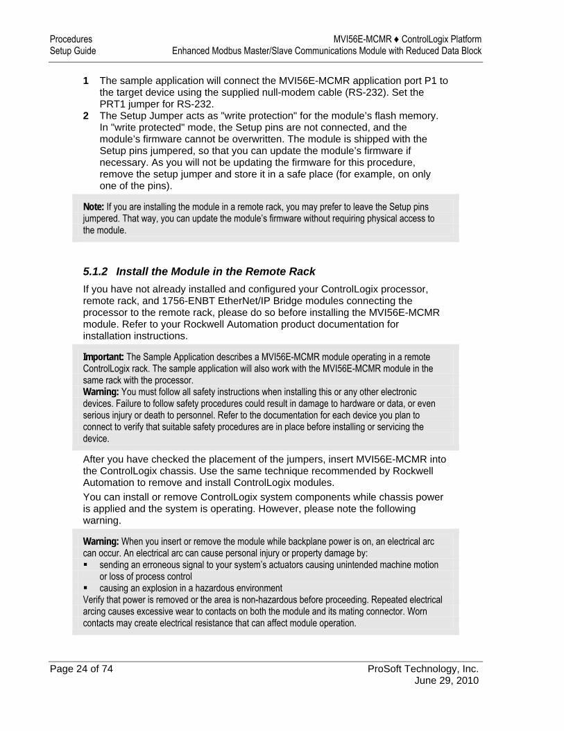
1 Align the module with the top and bottom guides, and then slide it into the rack until the module is firmly against the backplane connector.
2 With a firm but steady push, snap the module into place. 3 Check that the holding clips on the top and bottom of the module are securely
in the locking holes of the rack. 4 Make a note of the slot location. You must identify the slot in which the
module is installed in order for the sample program to work correctly. Slot numbers are identified on the green circuit board (backplane) of the ControlLogix rack.
5 Turn power ON.
Note: If you insert the module improperly, the system may stop working, or may behave unpredictably.
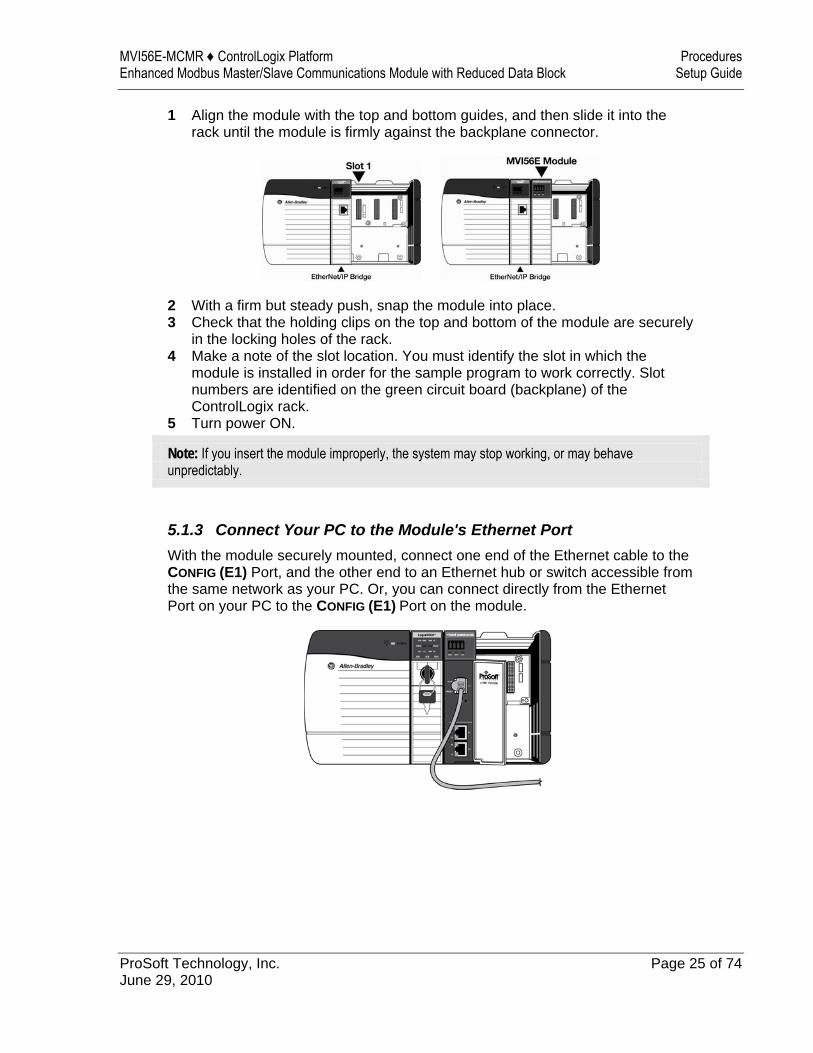
5.1.3 Connect Your PC to the Module's Ethernet Port With the module securely mounted, connect one end of the Ethernet cable to the CONFIG (E1) Port, and the other end to an Ethernet hub or switch accessible from the same network as your PC. Or, you can connect directly from the Ethernet Port on your PC to the CONFIG (E1) Port on the module.
Procedures MVI56E-MCMR ♦ ControlLogix Platform Setup Guide Enhanced Modbus Master/Slave Communications Module with Reduced Data Block
Page 26 of 74 ProSoft Technology, Inc. June 29, 2010
5.1.4 Set Temporary IP Address
Important: ProSoft Configuration Builder locates MVI56E-MCMR modules through UDP broadcast messages. These messages may be blocked by routers or layer 3 switches. In that case, ProSoft Discovery Service will be unable to locate the modules. To use ProSoft Configuration Builder, arrange the Ethernet connection so that there is no router/ layer 3 switch between the computer and the module OR reconfigure the router/layer 3 switch to allow the routing of the UDP broadcast messages.
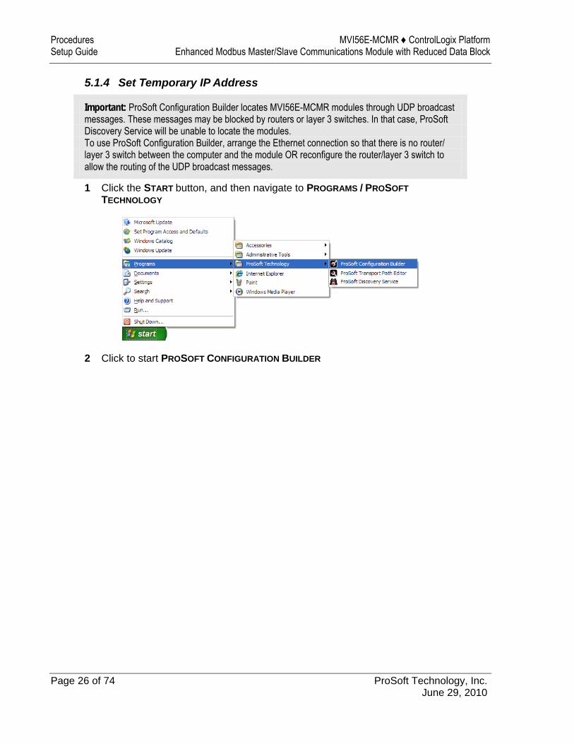
1 Click the START button, and then navigate to PROGRAMS / PROSOFT TECHNOLOGY
2 Click to start PROSOFT CONFIGURATION BUILDER
MVI56E-MCMR ♦ ControlLogix Platform Procedures Enhanced Modbus Master/Slave Communications Module with Reduced Data Block Setup Guide
ProSoft Technology, Inc. Page 27 of 74 June 29, 2010
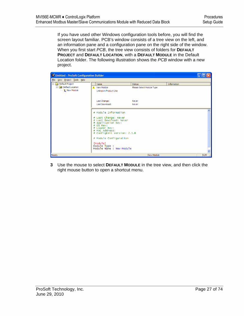
If you have used other Windows configuration tools before, you will find the screen layout familiar. PCB’s window consists of a tree view on the left, and an information pane and a configuration pane on the right side of the window. When you first start PCB, the tree view consists of folders for DEFAULT PROJECT and DEFAULT LOCATION, with a DEFAULT MODULE in the Default Location folder. The following illustration shows the PCB window with a new project.
3 Use the mouse to select DEFAULT MODULE in the tree view, and then click the right mouse button to open a shortcut menu.
Procedures MVI56E-MCMR ♦ ControlLogix Platform Setup Guide Enhanced Modbus Master/Slave Communications Module with Reduced Data Block
Page 28 of 74 ProSoft Technology, Inc. June 29, 2010
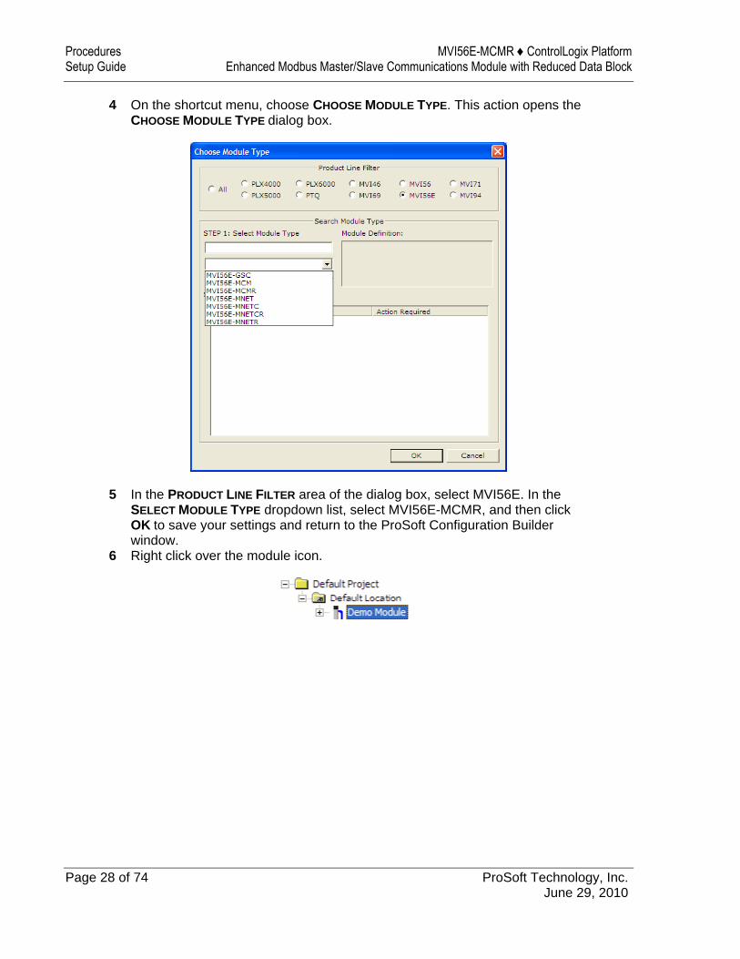
4 On the shortcut menu, choose CHOOSE MODULE TYPE. This action opens the CHOOSE MODULE TYPE dialog box.
5 In the PRODUCT LINE FILTER area of the dialog box, select MVI56E. In the SELECT MODULE TYPE dropdown list, select MVI56E-MCMR, and then click OK to save your settings and return to the ProSoft Configuration Builder window.
6 Right click over the module icon.
MVI56E-MCMR ♦ ControlLogix Platform Procedures Enhanced Modbus Master/Slave Communications Module with Reduced Data Block Setup Guide
ProSoft Technology, Inc. Page 29 of 74 June 29, 2010
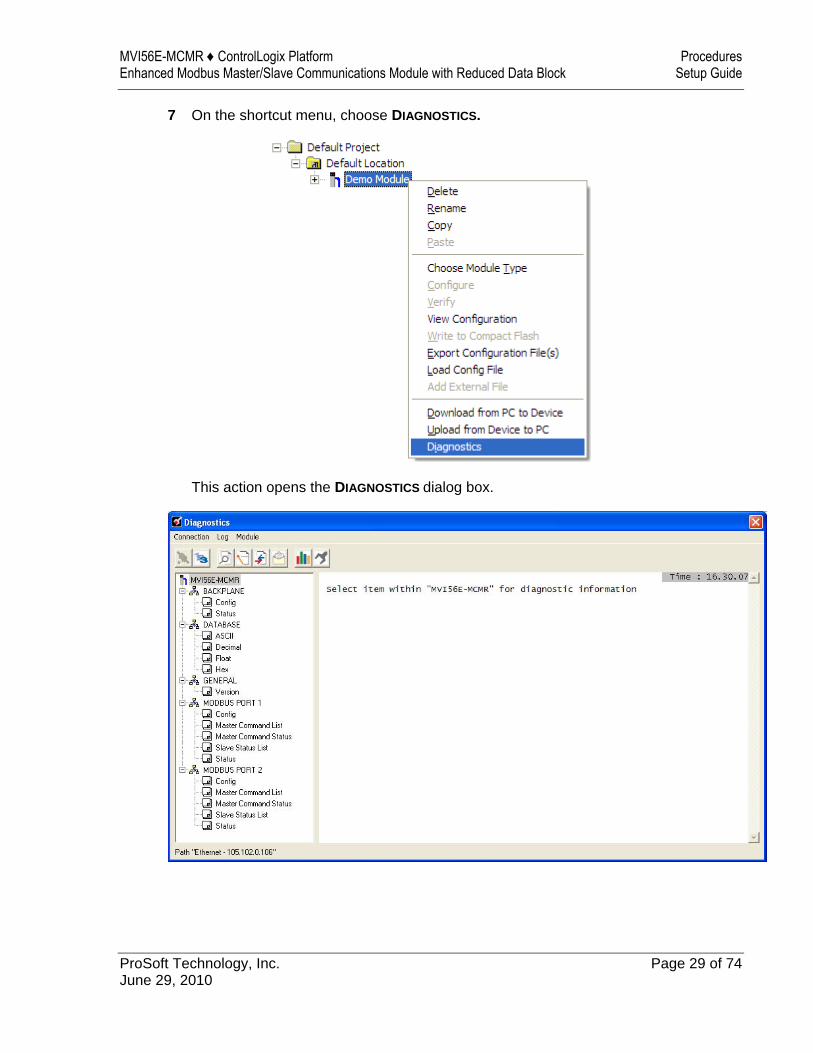
7 On the shortcut menu, choose DIAGNOSTICS.
This action opens the DIAGNOSTICS dialog box.
Procedures MVI56E-MCMR ♦ ControlLogix Platform Setup Guide Enhanced Modbus Master/Slave Communications Module with Reduced Data Block
Page 30 of 74 ProSoft Technology, Inc. June 29, 2010
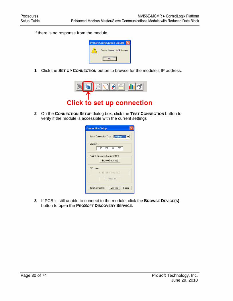
If there is no response from the module,
1 Click the SET UP CONNECTION button to browse for the module’s IP address.
2 On the CONNECTION SETUP dialog box, click the TEST CONNECTION button to verify if the module is accessible with the current settings
3 If PCB is still unable to connect to the module, click the BROWSE DEVICE(S) button to open the PROSOFT DISCOVERY SERVICE.
MVI56E-MCMR ♦ ControlLogix Platform Procedures Enhanced Modbus Master/Slave Communications Module with Reduced Data Block Setup Guide
ProSoft Technology, Inc. Page 31 of 74 June 29, 2010
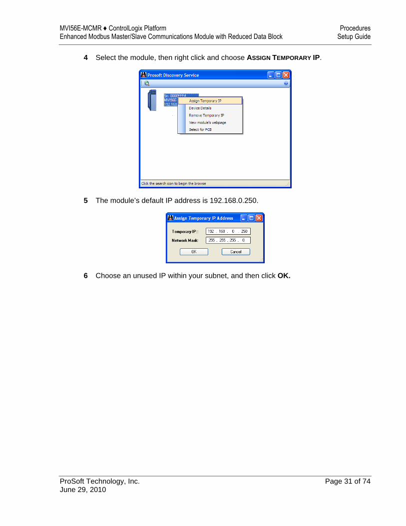
4 Select the module, then right click and choose ASSIGN TEMPORARY IP.
5 The module’s default IP address is 192.168.0.250.
6 Choose an unused IP within your subnet, and then click OK.

Procedures MVI56E-MCMR ♦ ControlLogix Platform Setup Guide Enhanced Modbus Master/Slave Communications Module with Reduced Data Block
Page 32 of 74 ProSoft Technology, Inc. June 29, 2010
CIPconnect You can use CIPconnect® to connect a PC to the MVI56E-MCMR module over Ethernet using Rockwell Automation’s 1756-ENBT EtherNet/IP® module. This allows you to configure the MVI56E-MCMR module and network, upload and download files, and view network and module diagnostics from a PC. RSLinx is not required when you use CIPconnect. All you need are: The IP addresses and slot numbers of any 1756-ENBT modules in the path The ControlNet node numbers and slot numbers of any 1756-CNBx
ControlNet Bridge modules in the path The slot number of the MVI56E-MCMR in the destination ControlLogix
chassis (the last ENBT/CNBx and chassis in the path). To use CIPconnect, follow these steps. 1 In the SET CONNECTION TYPE dropdown list, choose 1756-ENBT. The default
path appears in the text box, as shown in the following illustration.
MVI56E-MCMR ♦ ControlLogix Platform Procedures Enhanced Modbus Master/Slave Communications Module with Reduced Data Block Setup Guide
ProSoft Technology, Inc. Page 33 of 74 June 29, 2010
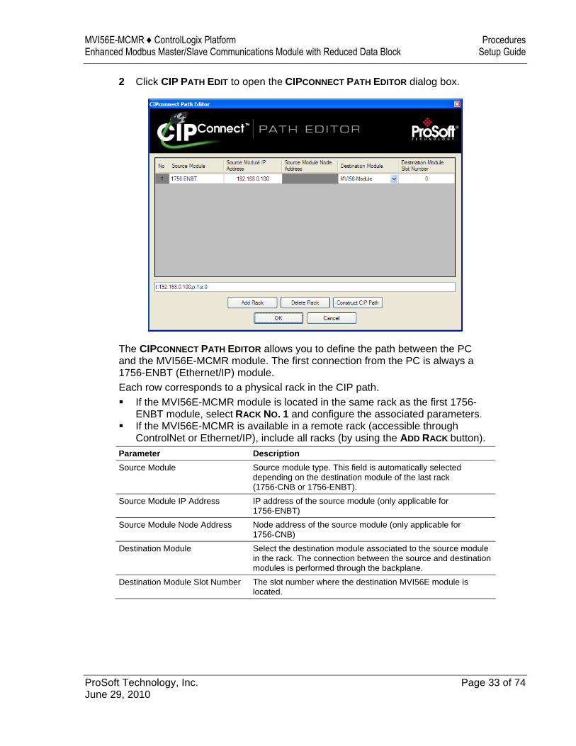
2 Click CIP PATH EDIT to open the CIPCONNECT PATH EDITOR dialog box.
The CIPCONNECT PATH EDITOR allows you to define the path between the PC and the MVI56E-MCMR module. The first connection from the PC is always a 1756-ENBT (Ethernet/IP) module. Each row corresponds to a physical rack in the CIP path. If the MVI56E-MCMR module is located in the same rack as the first 1756-
ENBT module, select RACK NO. 1 and configure the associated parameters. If the MVI56E-MCMR is available in a remote rack (accessible through
ControlNet or Ethernet/IP), include all racks (by using the ADD RACK button).
Parameter Description Source Module Source module type. This field is automatically selected
depending on the destination module of the last rack (1756-CNB or 1756-ENBT).
Source Module IP Address IP address of the source module (only applicable for 1756-ENBT)
Source Module Node Address Node address of the source module (only applicable for 1756-CNB)
Destination Module Select the destination module associated to the source module in the rack. The connection between the source and destination modules is performed through the backplane.
Destination Module Slot Number The slot number where the destination MVI56E module is located.
Procedures MVI56E-MCMR ♦ ControlLogix Platform Setup Guide Enhanced Modbus Master/Slave Communications Module with Reduced Data Block
Page 34 of 74 ProSoft Technology, Inc. June 29, 2010
To use the CIPconnect Path Editor, follow these steps. 1 Configure the path between the 1756-ENBT connected to your PC and the
MVI56E-MCMR module. o If the module is located in a remote rack, add more racks to configure the
full path. o The path can only contain ControlNet or Ethernet/IP networks. o The maximum number of supported racks is six.
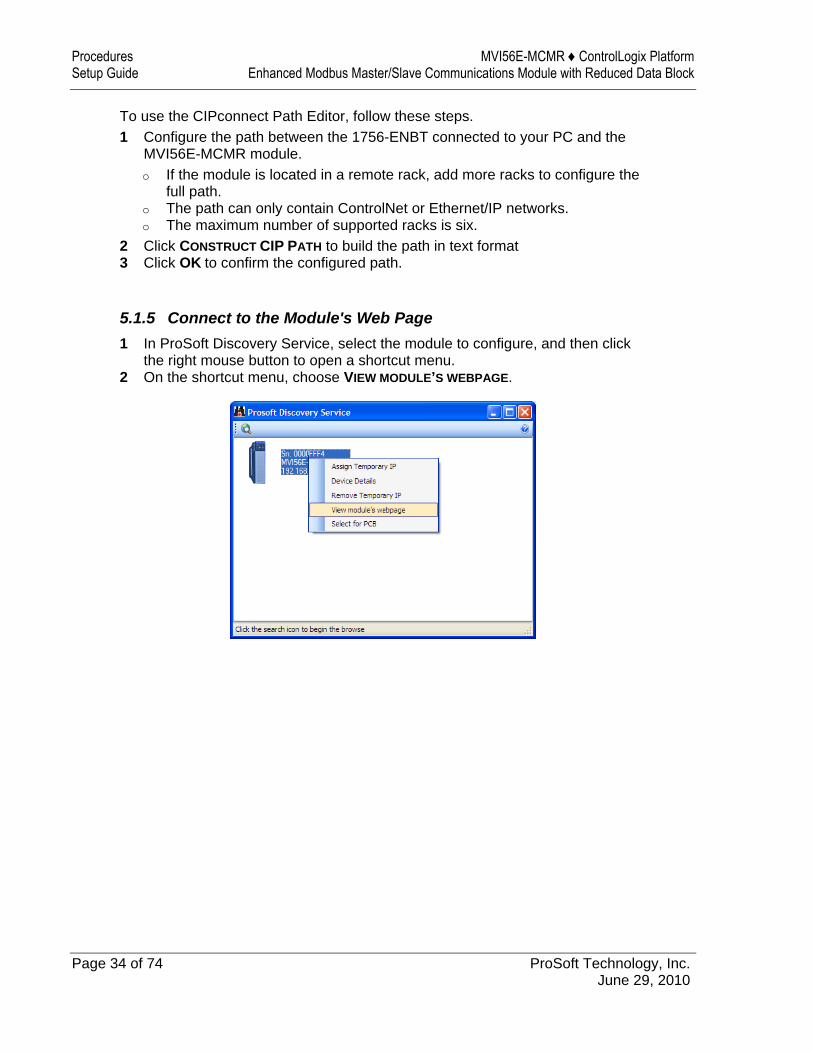
2 Click CONSTRUCT CIP PATH to build the path in text format 3 Click OK to confirm the configured path. 5.1.5 Connect to the Module's Web Page 1 In ProSoft Discovery Service, select the module to configure, and then click
the right mouse button to open a shortcut menu. 2 On the shortcut menu, choose VIEW MODULE’S WEBPAGE.
MVI56E-MCMR ♦ ControlLogix Platform Procedures Enhanced Modbus Master/Slave Communications Module with Reduced Data Block Setup Guide
ProSoft Technology, Inc. Page 35 of 74 June 29, 2010
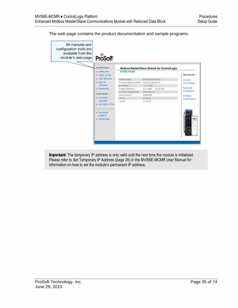
The web page contains the product documentation and sample programs.
Important: The temporary IP address is only valid until the next time the module is initialized. Please refer to Set Temporary IP Address (page 26) in the MVI56E-MCMR User Manual for information on how to set the module’s permanent IP address.
Procedures MVI56E-MCMR ♦ ControlLogix Platform Setup Guide Enhanced Modbus Master/Slave Communications Module with Reduced Data Block
Page 36 of 74 ProSoft Technology, Inc. June 29, 2010
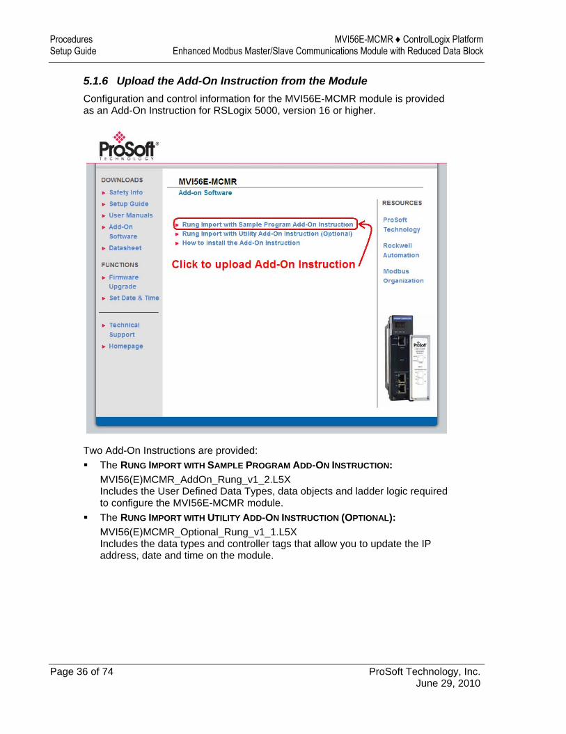
5.1.6 Upload the Add-On Instruction from the Module Configuration and control information for the MVI56E-MCMR module is provided as an Add-On Instruction for RSLogix 5000, version 16 or higher.
Two Add-On Instructions are provided: The RUNG IMPORT WITH SAMPLE PROGRAM ADD-ON INSTRUCTION:
MVI56(E)MCMR_AddOn_Rung_v1_2.L5X Includes the User Defined Data Types, data objects and ladder logic required to configure the MVI56E-MCMR module.
The RUNG IMPORT WITH UTILITY ADD-ON INSTRUCTION (OPTIONAL): MVI56(E)MCMR_Optional_Rung_v1_1.L5X Includes the data types and controller tags that allow you to update the IP address, date and time on the module.
MVI56E-MCMR ♦ ControlLogix Platform Procedures Enhanced Modbus Master/Slave Communications Module with Reduced Data Block Setup Guide
ProSoft Technology, Inc. Page 37 of 74 June 29, 2010
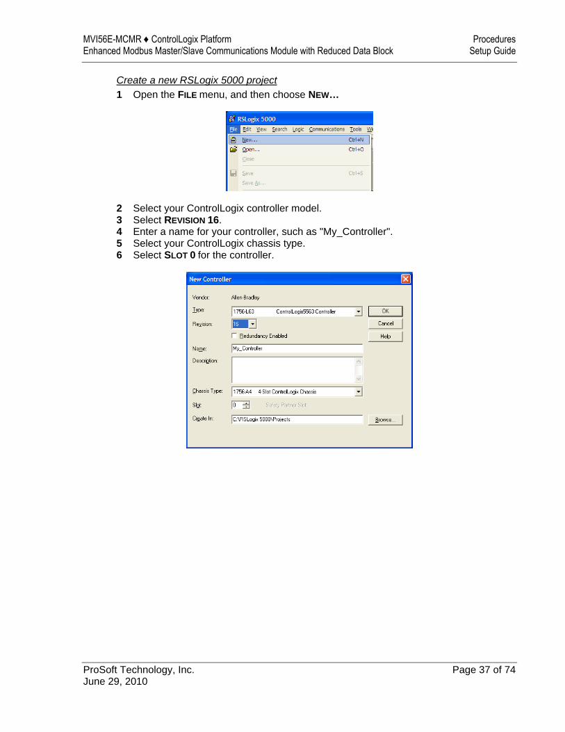
Create a new RSLogix 5000 project 1 Open the FILE menu, and then choose NEW…
2 Select your ControlLogix controller model. 3 Select REVISION 16. 4 Enter a name for your controller, such as "My_Controller". 5 Select your ControlLogix chassis type. 6 Select SLOT 0 for the controller.
Procedures MVI56E-MCMR ♦ ControlLogix Platform Setup Guide Enhanced Modbus Master/Slave Communications Module with Reduced Data Block
Page 38 of 74 ProSoft Technology, Inc. June 29, 2010
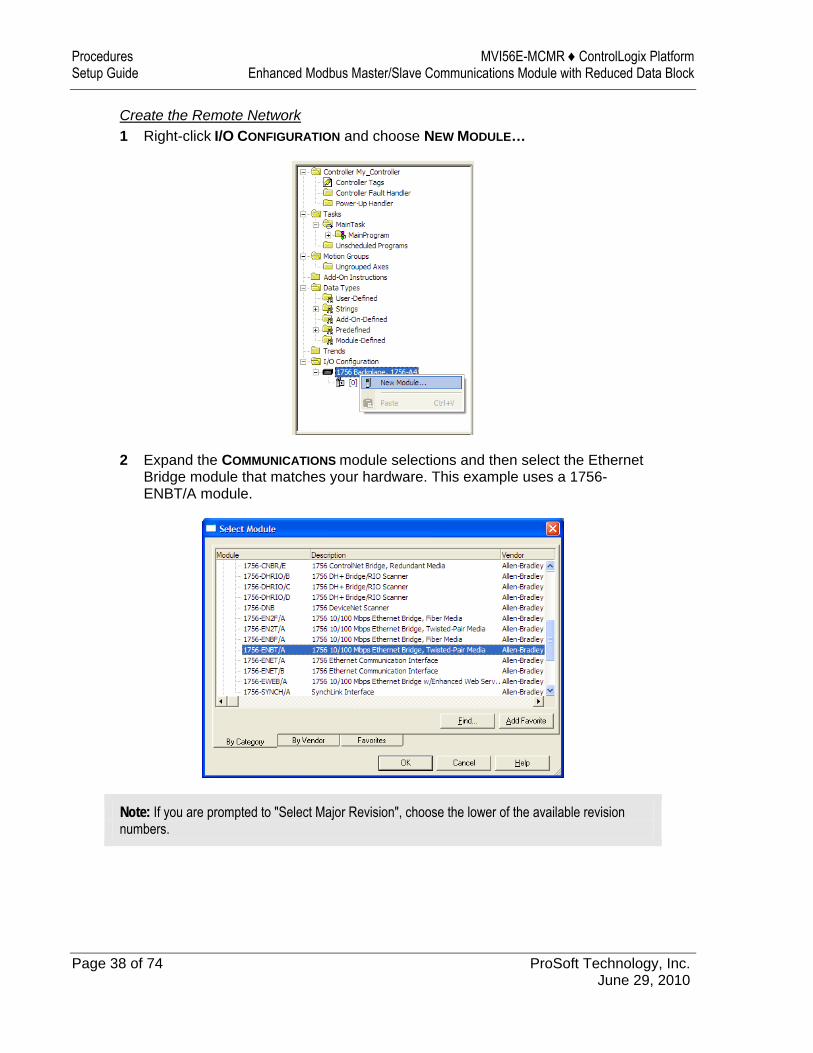
Create the Remote Network 1 Right-click I/O CONFIGURATION and choose NEW MODULE…
2 Expand the COMMUNICATIONS module selections and then select the Ethernet Bridge module that matches your hardware. This example uses a 1756-ENBT/A module.
Note: If you are prompted to "Select Major Revision", choose the lower of the available revision numbers.
MVI56E-MCMR ♦ ControlLogix Platform Procedures Enhanced Modbus Master/Slave Communications Module with Reduced Data Block Setup Guide
ProSoft Technology, Inc. Page 39 of 74 June 29, 2010
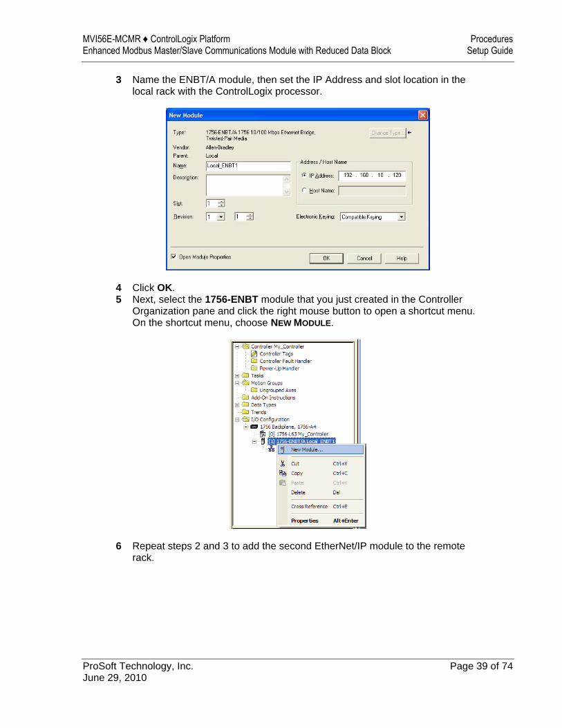
3 Name the ENBT/A module, then set the IP Address and slot location in the local rack with the ControlLogix processor.
4 Click OK. 5 Next, select the 1756-ENBT module that you just created in the Controller
Organization pane and click the right mouse button to open a shortcut menu. On the shortcut menu, choose NEW MODULE.
6 Repeat steps 2 and 3 to add the second EtherNet/IP module to the remote rack.
Procedures MVI56E-MCMR ♦ ControlLogix Platform Setup Guide Enhanced Modbus Master/Slave Communications Module with Reduced Data Block
Page 40 of 74 ProSoft Technology, Inc. June 29, 2010
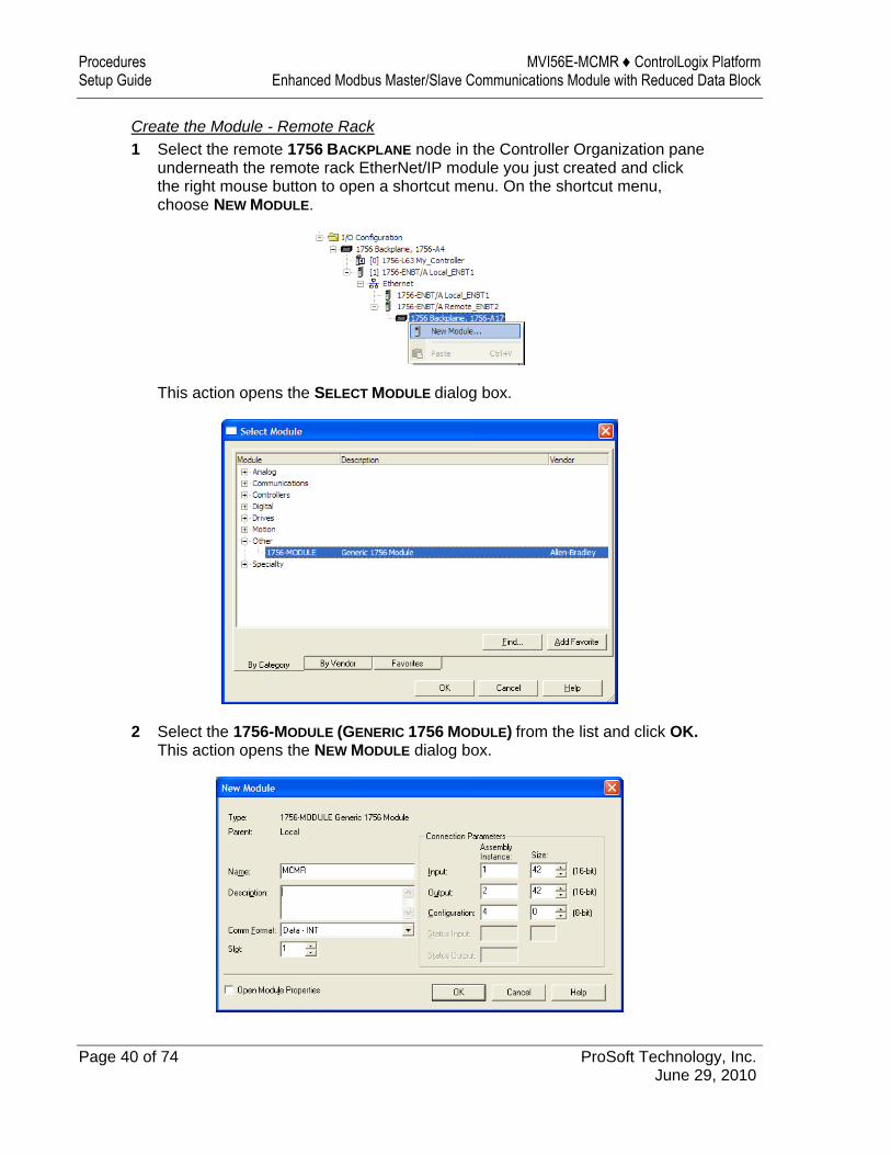
Create the Module - Remote Rack 1 Select the remote 1756 BACKPLANE node in the Controller Organization pane
underneath the remote rack EtherNet/IP module you just created and click the right mouse button to open a shortcut menu. On the shortcut menu, choose NEW MODULE.
This action opens the SELECT MODULE dialog box.
2 Select the 1756-MODULE (GENERIC 1756 MODULE) from the list and click OK. This action opens the NEW MODULE dialog box.
MVI56E-MCMR ♦ ControlLogix Platform Procedures Enhanced Modbus Master/Slave Communications Module with Reduced Data Block Setup Guide
ProSoft Technology, Inc. Page 41 of 74 June 29, 2010
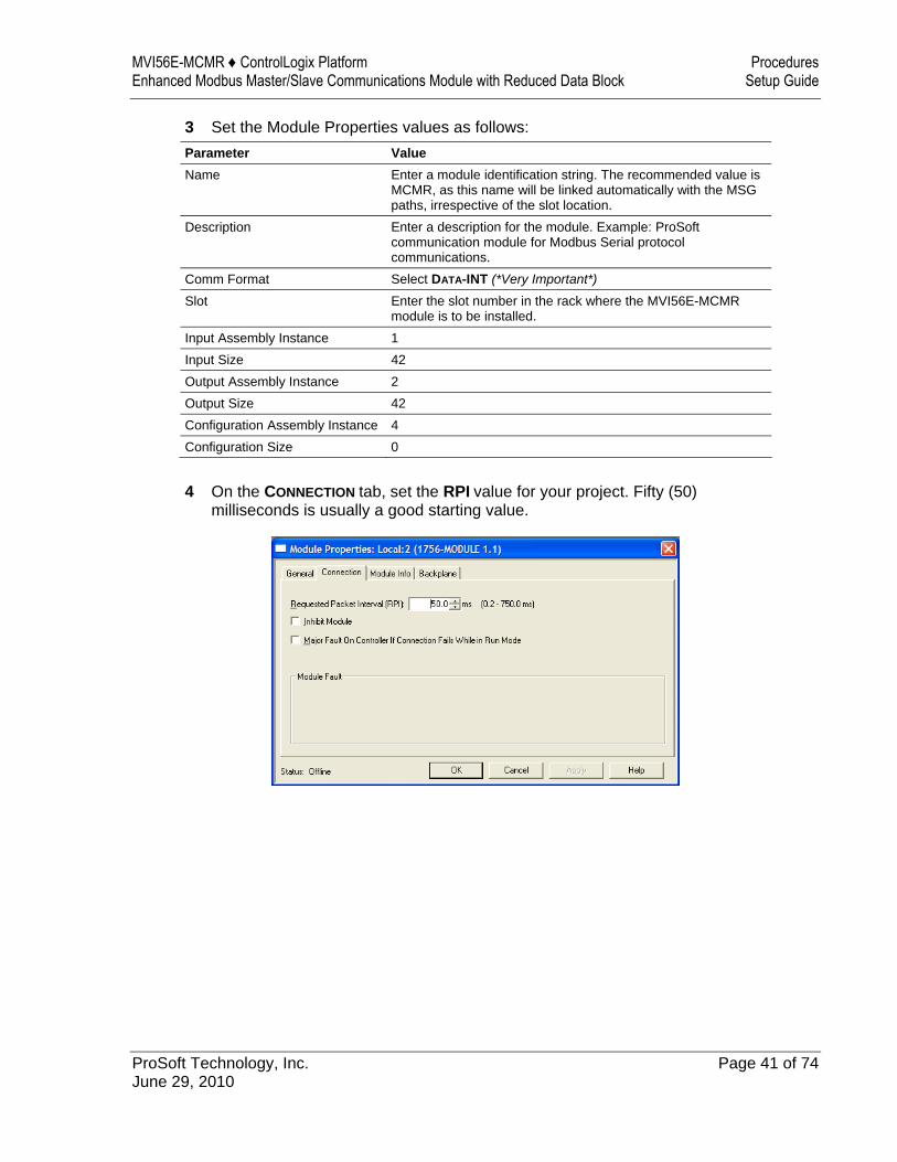
3 Set the Module Properties values as follows:
Parameter Value Name Enter a module identification string. The recommended value is
MCMR, as this name will be linked automatically with the MSG paths, irrespective of the slot location.
Description Enter a description for the module. Example: ProSoft communication module for Modbus Serial protocol communications.
Comm Format Select DATA-INT (*Very Important*) Slot Enter the slot number in the rack where the MVI56E-MCMR
module is to be installed. Input Assembly Instance 1 Input Size 42 Output Assembly Instance 2 Output Size 42 Configuration Assembly Instance 4 Configuration Size 0
4 On the CONNECTION tab, set the RPI value for your project. Fifty (50)
milliseconds is usually a good starting value.
Procedures MVI56E-MCMR ♦ ControlLogix Platform Setup Guide Enhanced Modbus Master/Slave Communications Module with Reduced Data Block
Page 42 of 74 ProSoft Technology, Inc. June 29, 2010
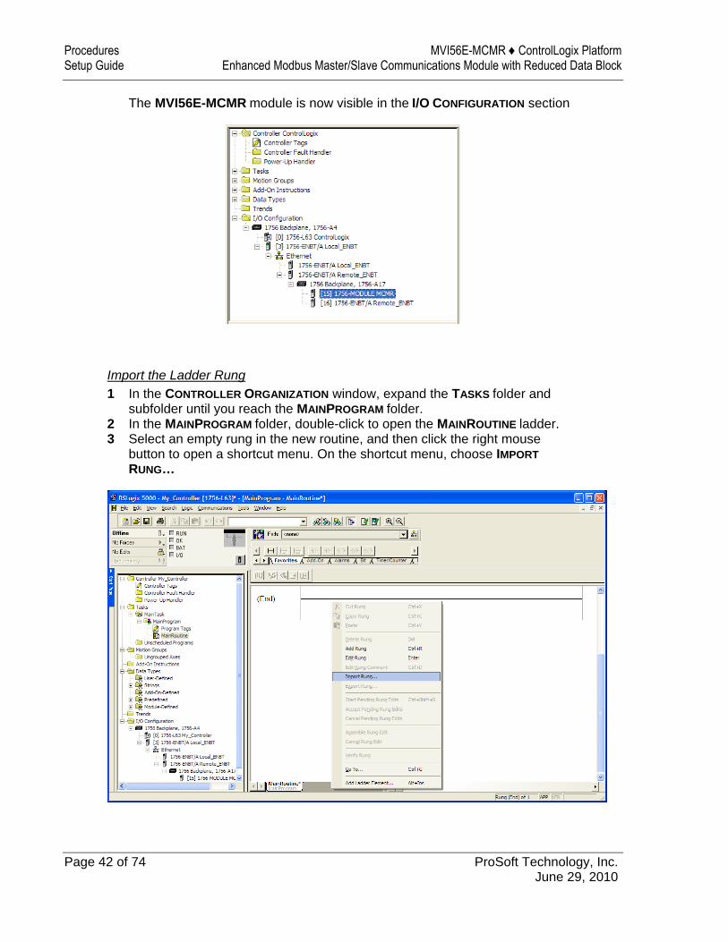
The MVI56E-MCMR module is now visible in the I/O CONFIGURATION section
Import the Ladder Rung 1 In the CONTROLLER ORGANIZATION window, expand the TASKS folder and
subfolder until you reach the MAINPROGRAM folder. 2 In the MAINPROGRAM folder, double-click to open the MAINROUTINE ladder. 3 Select an empty rung in the new routine, and then click the right mouse
button to open a shortcut menu. On the shortcut menu, choose IMPORT RUNG…
MVI56E-MCMR ♦ ControlLogix Platform Procedures Enhanced Modbus Master/Slave Communications Module with Reduced Data Block Setup Guide
ProSoft Technology, Inc. Page 43 of 74 June 29, 2010
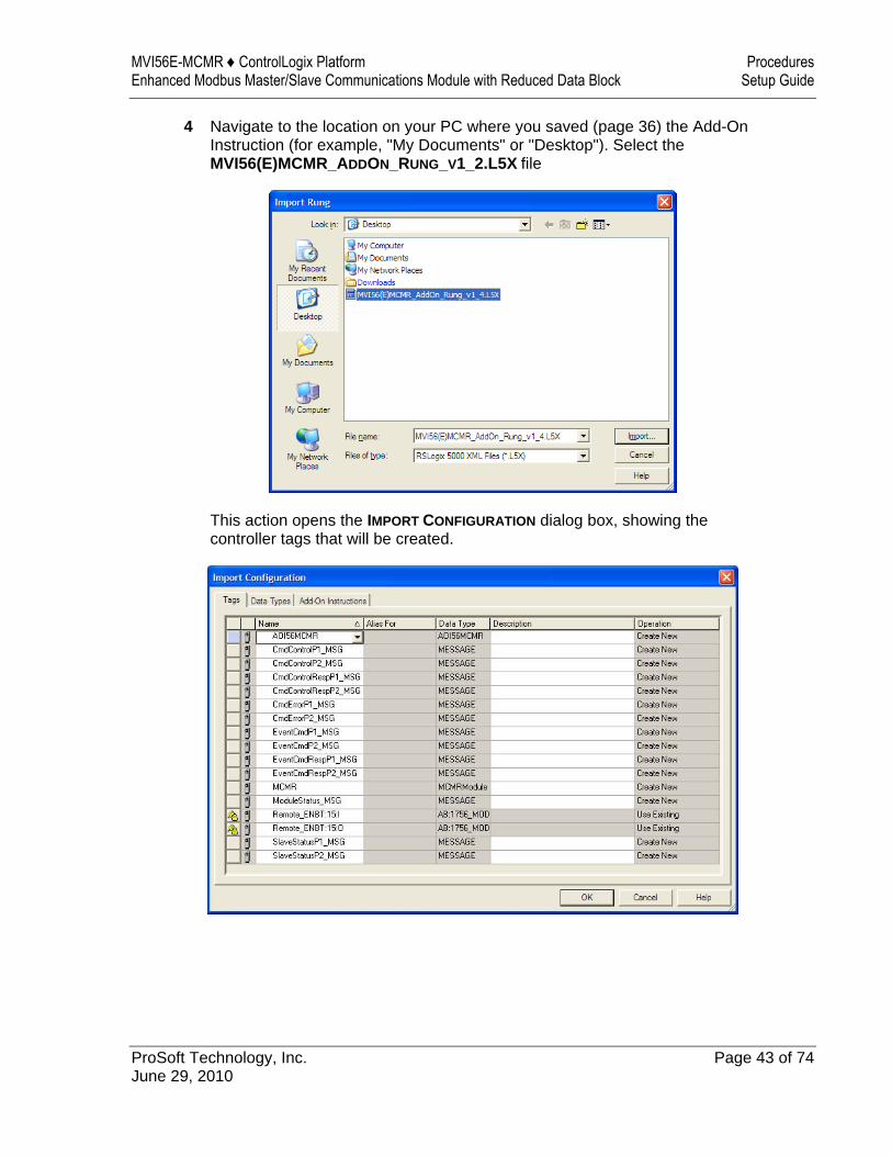
4 Navigate to the location on your PC where you saved (page 36) the Add-On Instruction (for example, "My Documents" or "Desktop"). Select the MVI56(E)MCMR_ADDON_RUNG_V1_2.L5X file
This action opens the IMPORT CONFIGURATION dialog box, showing the controller tags that will be created.
Procedures MVI56E-MCMR ♦ ControlLogix Platform Setup Guide Enhanced Modbus Master/Slave Communications Module with Reduced Data Block
Page 44 of 74 ProSoft Technology, Inc. June 29, 2010
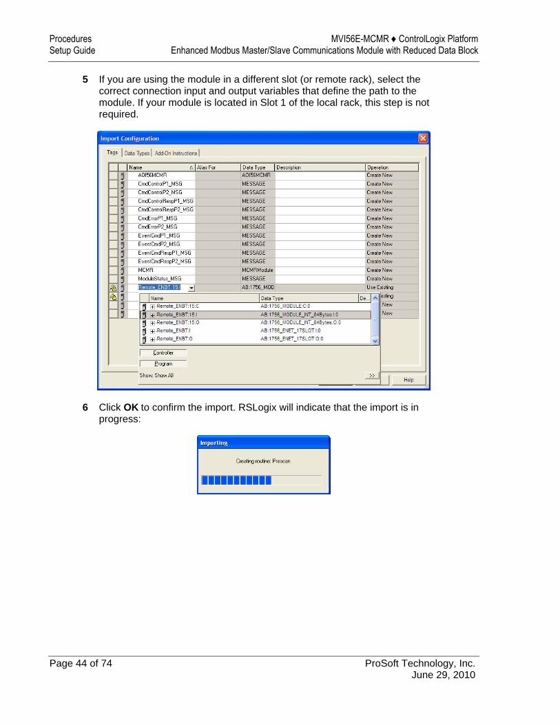
5 If you are using the module in a different slot (or remote rack), select the correct connection input and output variables that define the path to the module. If your module is located in Slot 1 of the local rack, this step is not required.
6 Click OK to confirm the import. RSLogix will indicate that the import is in progress:
MVI56E-MCMR ♦ ControlLogix Platform Procedures Enhanced Modbus Master/Slave Communications Module with Reduced Data Block Setup Guide
ProSoft Technology, Inc. Page 45 of 74 June 29, 2010
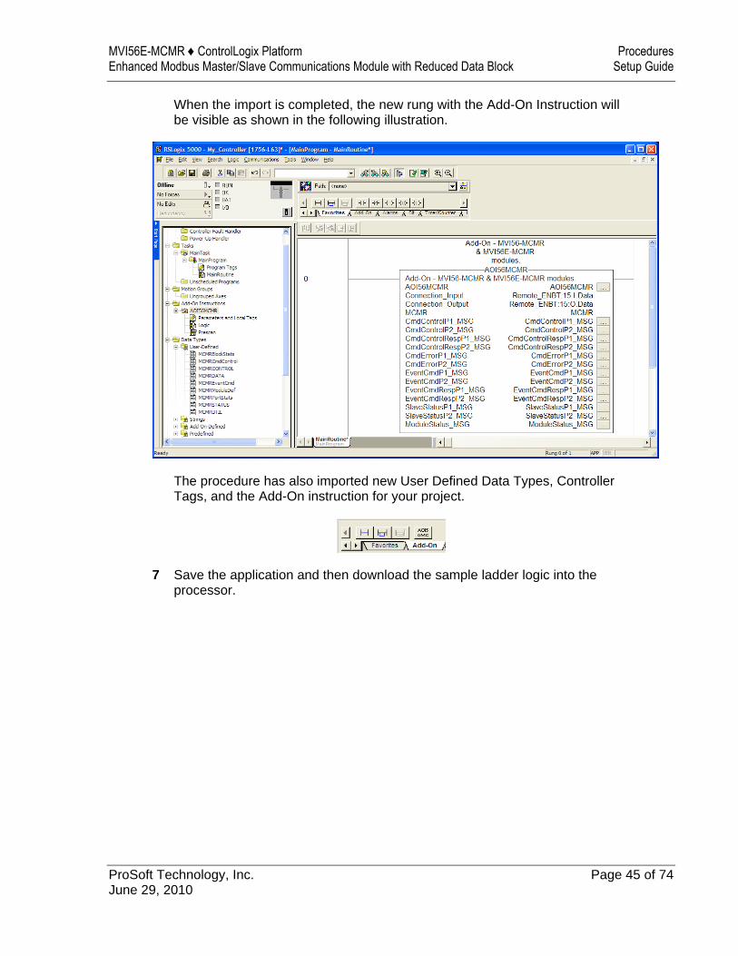
When the import is completed, the new rung with the Add-On Instruction will be visible as shown in the following illustration.
The procedure has also imported new User Defined Data Types, Controller Tags, and the Add-On instruction for your project.
7 Save the application and then download the sample ladder logic into the processor.
Procedures MVI56E-MCMR ♦ ControlLogix Platform Setup Guide Enhanced Modbus Master/Slave Communications Module with Reduced Data Block
Page 46 of 74 ProSoft Technology, Inc. June 29, 2010
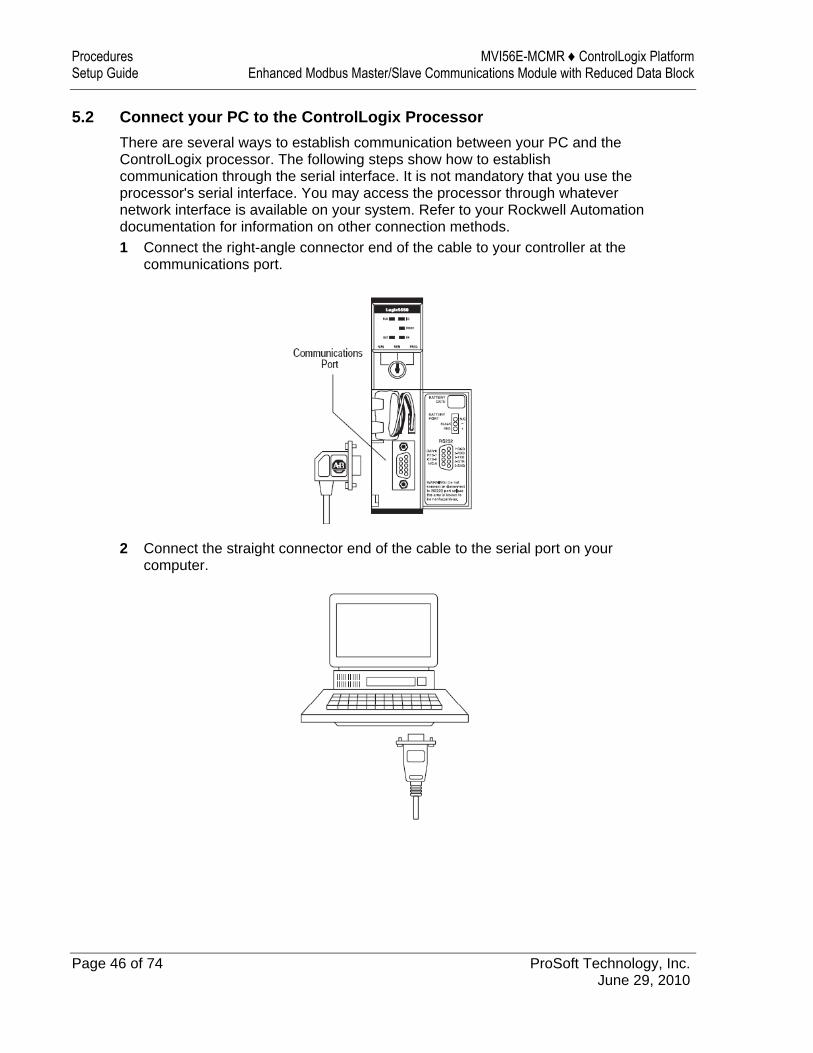
5.2 Connect your PC to the ControlLogix Processor There are several ways to establish communication between your PC and the ControlLogix processor. The following steps show how to establish communication through the serial interface. It is not mandatory that you use the processor's serial interface. You may access the processor through whatever network interface is available on your system. Refer to your Rockwell Automation documentation for information on other connection methods. 1 Connect the right-angle connector end of the cable to your controller at the
communications port.
2 Connect the straight connector end of the cable to the serial port on your computer.
MVI56E-MCMR ♦ ControlLogix Platform Procedures Enhanced Modbus Master/Slave Communications Module with Reduced Data Block Setup Guide
ProSoft Technology, Inc. Page 47 of 74 June 29, 2010
5.3 Download the Sample Program to the Processor
Note: The key switch on the front of the ControlLogix processor must be in the REM or PROG position.
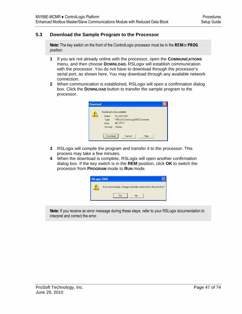
1 If you are not already online with the processor, open the COMMUNICATIONS menu, and then choose DOWNLOAD. RSLogix will establish communication with the processor. You do not have to download through the processor's serial port, as shown here. You may download through any available network connection.
2 When communication is established, RSLogix will open a confirmation dialog box. Click the DOWNLOAD button to transfer the sample program to the processor.
3 RSLogix will compile the program and transfer it to the processor. This process may take a few minutes.
4 When the download is complete, RSLogix will open another confirmation dialog box. If the key switch is in the REM position, click OK to switch the processor from PROGRAM mode to RUN mode.
Note: If you receive an error message during these steps, refer to your RSLogix documentation to interpret and correct the error.
Procedures MVI56E-MCMR ♦ ControlLogix Platform Setup Guide Enhanced Modbus Master/Slave Communications Module with Reduced Data Block
Page 48 of 74 ProSoft Technology, Inc. June 29, 2010
5.4 Using ProSoft Configuration Builder Software ProSoft Configuration Builder (PCB) provides a quick and easy way to manage gateway configuration files customized to meet your application needs. PCB is not only a powerful solution for new configuration files, but also allows you to import information from previously installed (known working) configurations to new projects.
Note: The MVI56E-MCMR module receives its protocol and backplane configuration information from the Personality Module (Compact Flash). Use ProSoft Configuration Builder to configure module settings, and to download changes to the Personality Module.
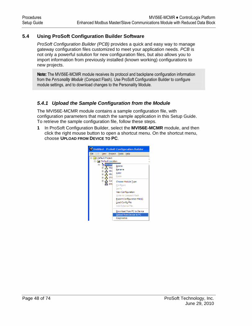
5.4.1 Upload the Sample Configuration from the Module The MVI56E-MCMR module contains a sample configuration file, with configuration parameters that match the sample application in this Setup Guide. To retrieve the sample configuration file, follow these steps. 1 In ProSoft Configuration Builder, select the MVI56E-MCMR module, and then
click the right mouse button to open a shortcut menu. On the shortcut menu, choose UPLOAD FROM DEVICE TO PC.
MVI56E-MCMR ♦ ControlLogix Platform Procedures Enhanced Modbus Master/Slave Communications Module with Reduced Data Block Setup Guide
ProSoft Technology, Inc. Page 49 of 74 June 29, 2010
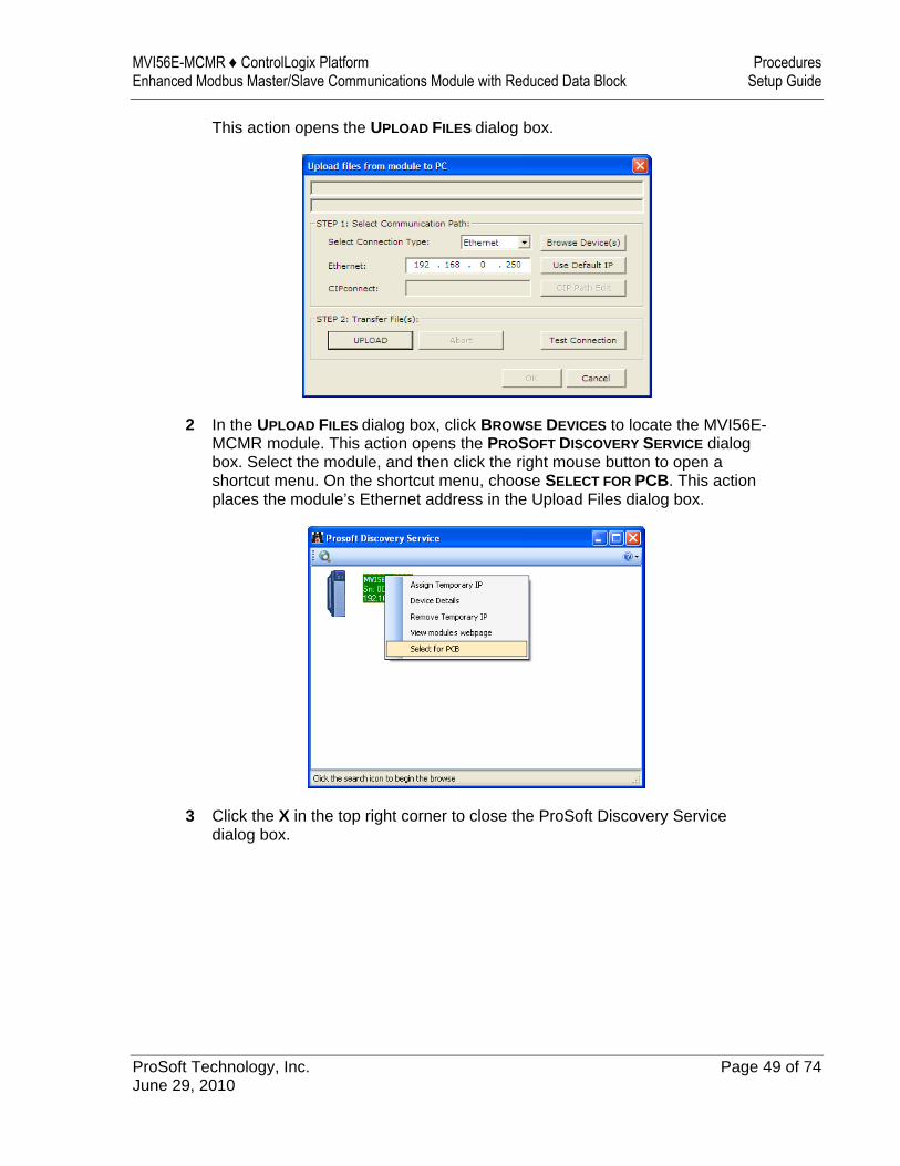
This action opens the UPLOAD FILES dialog box.
2 In the UPLOAD FILES dialog box, click BROWSE DEVICES to locate the MVI56E-MCMR module. This action opens the PROSOFT DISCOVERY SERVICE dialog box. Select the module, and then click the right mouse button to open a shortcut menu. On the shortcut menu, choose SELECT FOR PCB. This action places the module’s Ethernet address in the Upload Files dialog box.
3 Click the X in the top right corner to close the ProSoft Discovery Service dialog box.
Procedures MVI56E-MCMR ♦ ControlLogix Platform Setup Guide Enhanced Modbus Master/Slave Communications Module with Reduced Data Block
Page 50 of 74 ProSoft Technology, Inc. June 29, 2010
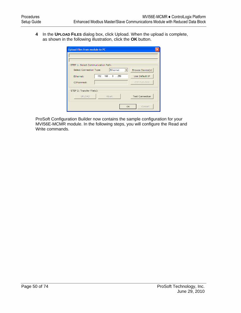
4 In the UPLOAD FILES dialog box, click Upload. When the upload is complete, as shown in the following illustration, click the OK button.
ProSoft Configuration Builder now contains the sample configuration for your MVI56E-MCMR module. In the following steps, you will configure the Read and Write commands.
MVI56E-MCMR ♦ ControlLogix Platform Procedures Enhanced Modbus Master/Slave Communications Module with Reduced Data Block Setup Guide
ProSoft Technology, Inc. Page 51 of 74 June 29, 2010
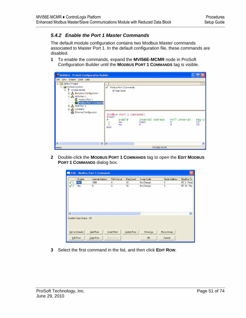
5.4.2 Enable the Port 1 Master Commands The default module configuration contains two Modbus Master commands associated to Master Port 1. In the default configuration file, these commands are disabled. 1 To enable the commands, expand the MVI56E-MCMR node in ProSoft
Configuration Builder until the MODBUS PORT 1 COMMANDS tag is visible.
2 Double-click the MODBUS PORT 1 COMMANDS tag to open the EDIT MODBUS PORT 1 COMMANDS dialog box.
3 Select the first command in the list, and then click EDIT ROW.
Procedures MVI56E-MCMR ♦ ControlLogix Platform Setup Guide Enhanced Modbus Master/Slave Communications Module with Reduced Data Block
Page 52 of 74 ProSoft Technology, Inc. June 29, 2010
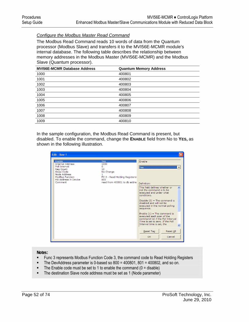
Configure the Modbus Master Read Command The Modbus Read Command reads 10 words of data from the Quantum processor (Modbus Slave) and transfers it to the MVI56E-MCMR module's internal database. The following table describes the relationship between memory addresses in the Modbus Master (MVI56E-MCMR) and the Modbus Slave (Quantum processor). MVI56E-MCMR Database Address Quantum Memory Address 1000 400801 1001 400802 1002 400803 1003 400804 1004 400805 1005 400806 1006 400807 1007 400808 1008 400809 1009 400810
In the sample configuration, the Modbus Read Command is present, but disabled. To enable the command, change the ENABLE field from No to YES, as shown in the following illustration.
Notes: Func 3 represents Modbus Function Code 3, the command code to Read Holding Registers The DevAddress parameter is 0-based so 800 = 400801, 801 = 400802, and so on. The Enable code must be set to 1 to enable the command (0 = disable) The destination Slave node address must be set as 1 (Node parameter)
MVI56E-MCMR ♦ ControlLogix Platform Procedures Enhanced Modbus Master/Slave Communications Module with Reduced Data Block Setup Guide
ProSoft Technology, Inc. Page 53 of 74 June 29, 2010
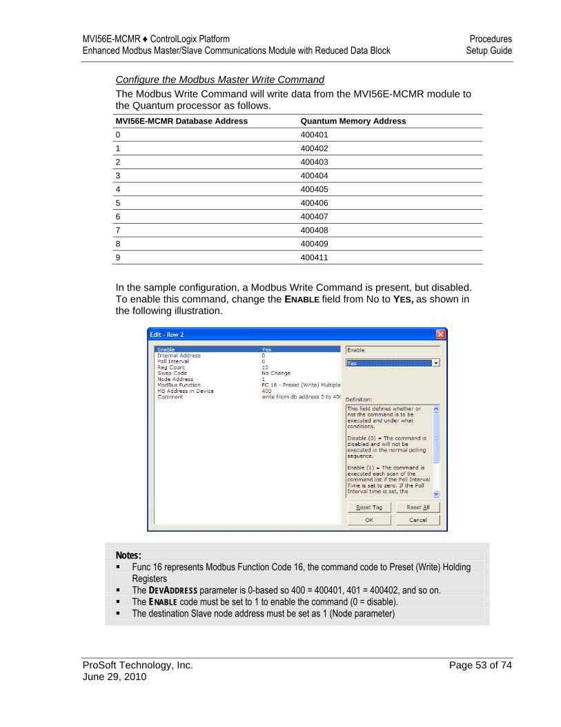
Configure the Modbus Master Write Command The Modbus Write Command will write data from the MVI56E-MCMR module to the Quantum processor as follows. MVI56E-MCMR Database Address Quantum Memory Address 0 400401 1 400402 2 400403 3 400404 4 400405 5 400406 6 400407 7 400408 8 400409 9 400411
In the sample configuration, a Modbus Write Command is present, but disabled. To enable this command, change the ENABLE field from No to YES, as shown in the following illustration.
Notes: Func 16 represents Modbus Function Code 16, the command code to Preset (Write) Holding
Registers The DEVADDRESS parameter is 0-based so 400 = 400401, 401 = 400402, and so on. The ENABLE code must be set to 1 to enable the command (0 = disable). The destination Slave node address must be set as 1 (Node parameter)
Procedures MVI56E-MCMR ♦ ControlLogix Platform Setup Guide Enhanced Modbus Master/Slave Communications Module with Reduced Data Block
Page 54 of 74 ProSoft Technology, Inc. June 29, 2010
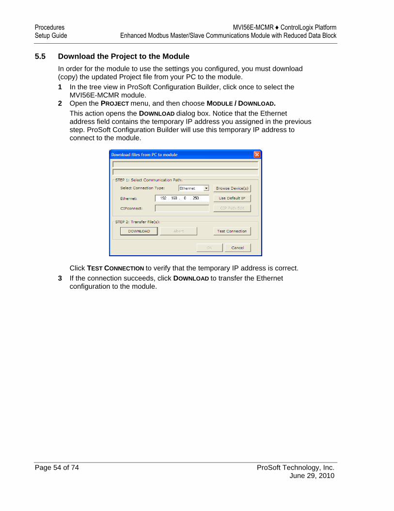
5.5 Download the Project to the Module In order for the module to use the settings you configured, you must download (copy) the updated Project file from your PC to the module. 1 In the tree view in ProSoft Configuration Builder, click once to select the
MVI56E-MCMR module. 2 Open the PROJECT menu, and then choose MODULE / DOWNLOAD.
This action opens the DOWNLOAD dialog box. Notice that the Ethernet address field contains the temporary IP address you assigned in the previous step. ProSoft Configuration Builder will use this temporary IP address to connect to the module.
Click TEST CONNECTION to verify that the temporary IP address is correct. 3 If the connection succeeds, click DOWNLOAD to transfer the Ethernet
configuration to the module.
MVI56E-MCMR ♦ ControlLogix Platform Procedures Enhanced Modbus Master/Slave Communications Module with Reduced Data Block Setup Guide
ProSoft Technology, Inc. Page 55 of 74 June 29, 2010
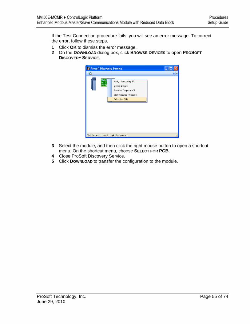
If the Test Connection procedure fails, you will see an error message. To correct the error, follow these steps. 1 Click OK to dismiss the error message. 2 On the DOWNLOAD dialog box, click BROWSE DEVICES to open PROSOFT
DISCOVERY SERVICE.
3 Select the module, and then click the right mouse button to open a shortcut menu. On the shortcut menu, choose SELECT FOR PCB.
4 Close ProSoft Discovery Service. 5 Click DOWNLOAD to transfer the configuration to the module.
Procedures MVI56E-MCMR ♦ ControlLogix Platform Setup Guide Enhanced Modbus Master/Slave Communications Module with Reduced Data Block
Page 56 of 74 ProSoft Technology, Inc. June 29, 2010
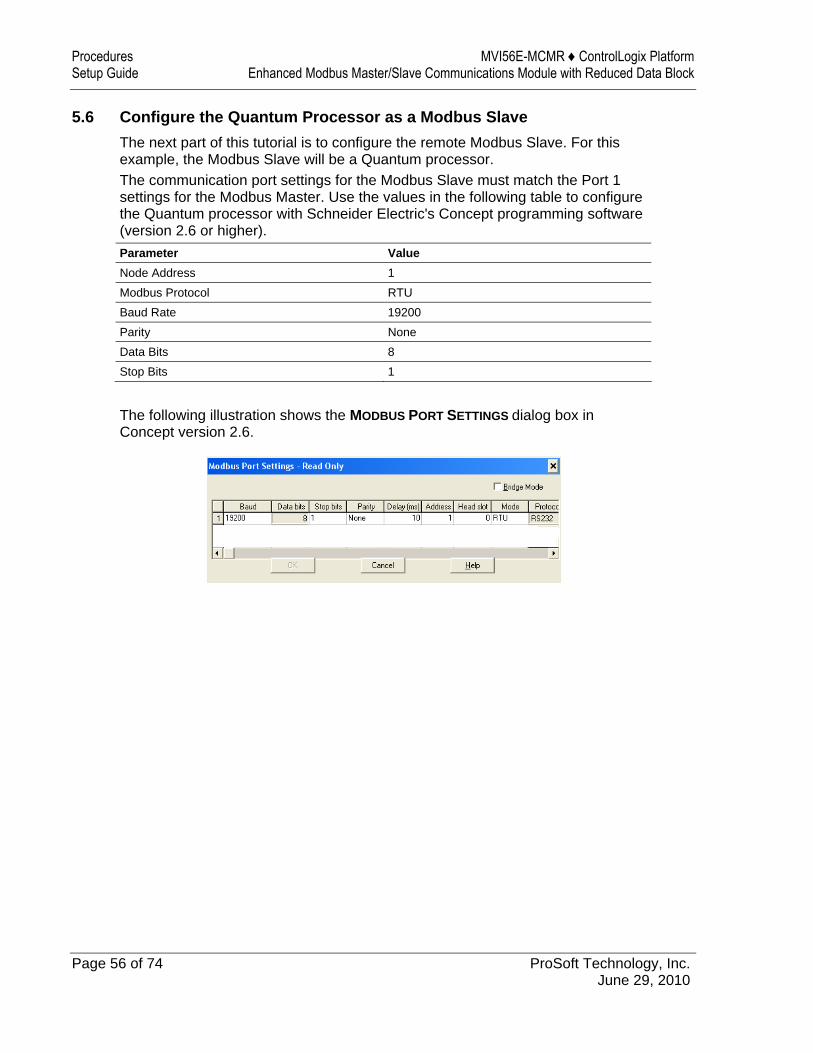
5.6 Configure the Quantum Processor as a Modbus Slave The next part of this tutorial is to configure the remote Modbus Slave. For this example, the Modbus Slave will be a Quantum processor. The communication port settings for the Modbus Slave must match the Port 1 settings for the Modbus Master. Use the values in the following table to configure the Quantum processor with Schneider Electric's Concept programming software (version 2.6 or higher). Parameter Value Node Address 1 Modbus Protocol RTU Baud Rate 19200 Parity None Data Bits 8 Stop Bits 1
The following illustration shows the MODBUS PORT SETTINGS dialog box in Concept version 2.6.
MVI56E-MCMR ♦ ControlLogix Platform Procedures Enhanced Modbus Master/Slave Communications Module with Reduced Data Block Setup Guide
ProSoft Technology, Inc. Page 57 of 74 June 29, 2010
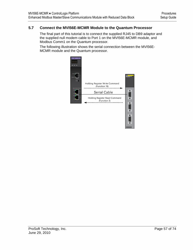
5.7 Connect the MVI56E-MCMR Module to the Quantum Processor The final part of this tutorial is to connect the supplied RJ45 to DB9 adaptor and the supplied null modem cable to Port 1 on the MVI56E-MCMR module, and Modbus Comm1 on the Quantum processor. The following illustration shows the serial connection between the MVI56E-MCMR module and the Quantum processor.
Procedures MVI56E-MCMR ♦ ControlLogix Platform Setup Guide Enhanced Modbus Master/Slave Communications Module with Reduced Data Block
Page 58 of 74 ProSoft Technology, Inc. June 29, 2010
5.8 Verify Communication There are several ways to verify that the MVI56E-MCMR module is communicating with the processor and with the Modbus Master/Slave network. You can: View Exchanged Data View the Module Status in the RSLogix 5000 Controller Tags View the LED Status Indicators
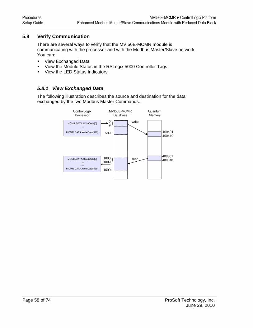
5.8.1 View Exchanged Data The following illustration describes the source and destination for the data exchanged by the two Modbus Master Commands.
MVI56E-MCMR ♦ ControlLogix Platform Procedures Enhanced Modbus Master/Slave Communications Module with Reduced Data Block Setup Guide
ProSoft Technology, Inc. Page 59 of 74 June 29, 2010
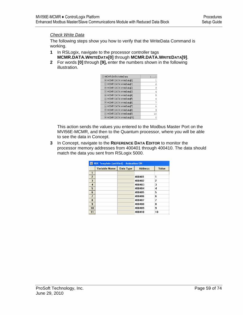
Check Write Data The following steps show you how to verify that the WriteData Command is working. 1 In RSLogix, navigate to the processor controller tags
MCMR.DATA.WRITEDATA[0] through MCMR.DATA.WRITEDATA[9]. 2 For words [0] through [9], enter the numbers shown in the following
illustration.
This action sends the values you entered to the Modbus Master Port on the MVI56E-MCMR, and then to the Quantum processor, where you will be able to see the data in Concept.
3 In Concept, navigate to the REFERENCE DATA EDITOR to monitor the processor memory addresses from 400401 through 400410. The data should match the data you sent from RSLogix 5000.
Procedures MVI56E-MCMR ♦ ControlLogix Platform Setup Guide Enhanced Modbus Master/Slave Communications Module with Reduced Data Block
Page 60 of 74 ProSoft Technology, Inc. June 29, 2010
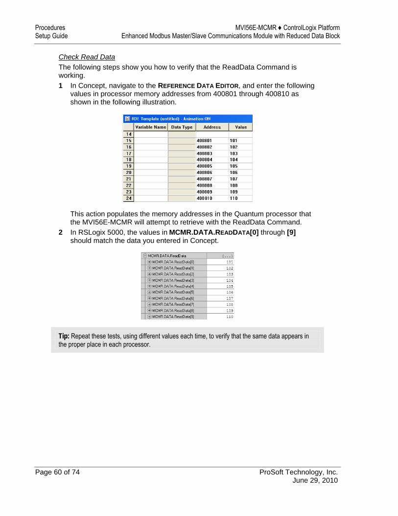
Check Read Data The following steps show you how to verify that the ReadData Command is working. 1 In Concept, navigate to the REFERENCE DATA EDITOR, and enter the following
values in processor memory addresses from 400801 through 400810 as shown in the following illustration.
This action populates the memory addresses in the Quantum processor that the MVI56E-MCMR will attempt to retrieve with the ReadData Command.
2 In RSLogix 5000, the values in MCMR.DATA.READDATA[0] through [9] should match the data you entered in Concept.
Tip: Repeat these tests, using different values each time, to verify that the same data appears in the proper place in each processor.
MVI56E-MCMR ♦ ControlLogix Platform Procedures Enhanced Modbus Master/Slave Communications Module with Reduced Data Block Setup Guide
ProSoft Technology, Inc. Page 61 of 74 June 29, 2010
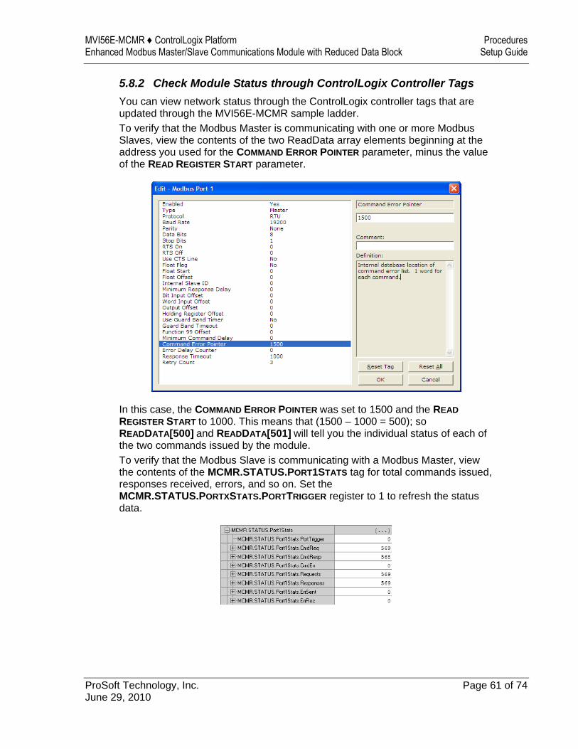
5.8.2 Check Module Status through ControlLogix Controller Tags You can view network status through the ControlLogix controller tags that are updated through the MVI56E-MCMR sample ladder. To verify that the Modbus Master is communicating with one or more Modbus Slaves, view the contents of the two ReadData array elements beginning at the address you used for the COMMAND ERROR POINTER parameter, minus the value of the READ REGISTER START parameter.
In this case, the COMMAND ERROR POINTER was set to 1500 and the READ REGISTER START to 1000. This means that (1500 – 1000 = 500); so READDATA[500] and READDATA[501] will tell you the individual status of each of the two commands issued by the module. To verify that the Modbus Slave is communicating with a Modbus Master, view the contents of the MCMR.STATUS.PORT1STATS tag for total commands issued, responses received, errors, and so on. Set the MCMR.STATUS.PORTXSTATS.PORTTRIGGER register to 1 to refresh the status data.
Procedures MVI56E-MCMR ♦ ControlLogix Platform Setup Guide Enhanced Modbus Master/Slave Communications Module with Reduced Data Block
Page 62 of 74 ProSoft Technology, Inc. June 29, 2010
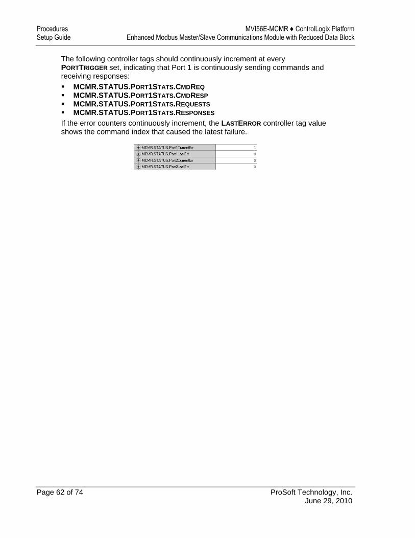
The following controller tags should continuously increment at every PORTTRIGGER set, indicating that Port 1 is continuously sending commands and receiving responses: MCMR.STATUS.PORT1STATS.CMDREQ MCMR.STATUS.PORT1STATS.CMDRESP MCMR.STATUS.PORT1STATS.REQUESTS MCMR.STATUS.PORT1STATS.RESPONSES
If the error counters continuously increment, the LASTERROR controller tag value shows the command index that caused the latest failure.
MVI56E-MCMR ♦ ControlLogix Platform Procedures Enhanced Modbus Master/Slave Communications Module with Reduced Data Block Setup Guide
ProSoft Technology, Inc. Page 63 of 74 June 29, 2010
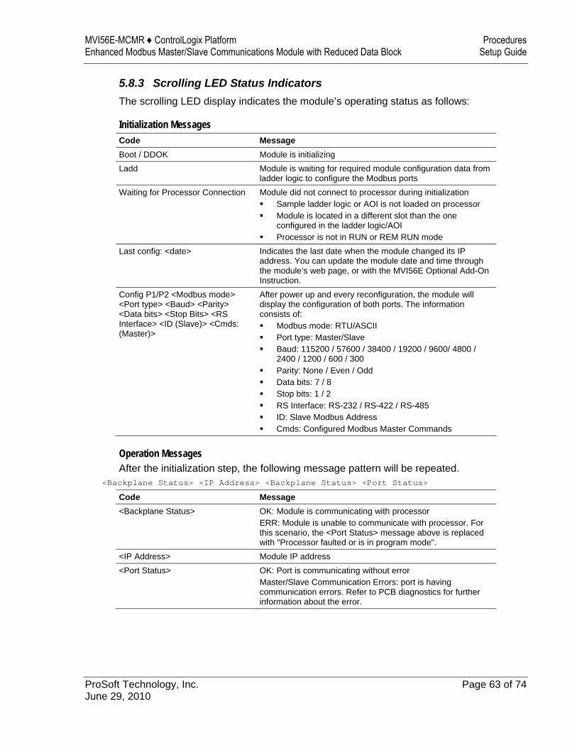
5.8.3 Scrolling LED Status Indicators The scrolling LED display indicates the module’s operating status as follows:
Initialization Messages Code Message Boot / DDOK Module is initializing Ladd Module is waiting for required module configuration data from
ladder logic to configure the Modbus ports Waiting for Processor Connection Module did not connect to processor during initialization
Sample ladder logic or AOI is not loaded on processor Module is located in a different slot than the one
configured in the ladder logic/AOI Processor is not in RUN or REM RUN mode
Last config: <date> Indicates the last date when the module changed its IP address. You can update the module date and time through the module’s web page, or with the MVI56E Optional Add-On Instruction.
Config P1/P2 <Modbus mode> <Port type> <Baud> <Parity> <Data bits> <Stop Bits> <RS Interface> <ID (Slave)> <Cmds: (Master)>
After power up and every reconfiguration, the module will display the configuration of both ports. The information consists of: Modbus mode: RTU/ASCII Port type: Master/Slave Baud: 115200 / 57600 / 38400 / 19200 / 9600/ 4800 /
2400 / 1200 / 600 / 300 Parity: None / Even / Odd Data bits: 7 / 8 Stop bits: 1 / 2 RS Interface: RS-232 / RS-422 / RS-485 ID: Slave Modbus Address Cmds: Configured Modbus Master Commands
Operation Messages After the initialization step, the following message pattern will be repeated.
<Backplane Status> <IP Address> <Backplane Status> <Port Status>
Code Message <Backplane Status> OK: Module is communicating with processor
ERR: Module is unable to communicate with processor. For this scenario, the <Port Status> message above is replaced with "Processor faulted or is in program mode".
<IP Address> Module IP address <Port Status> OK: Port is communicating without error
Master/Slave Communication Errors: port is having communication errors. Refer to PCB diagnostics for further information about the error.
Procedures MVI56E-MCMR ♦ ControlLogix Platform Setup Guide Enhanced Modbus Master/Slave Communications Module with Reduced Data Block
Page 64 of 74 ProSoft Technology, Inc. June 29, 2010
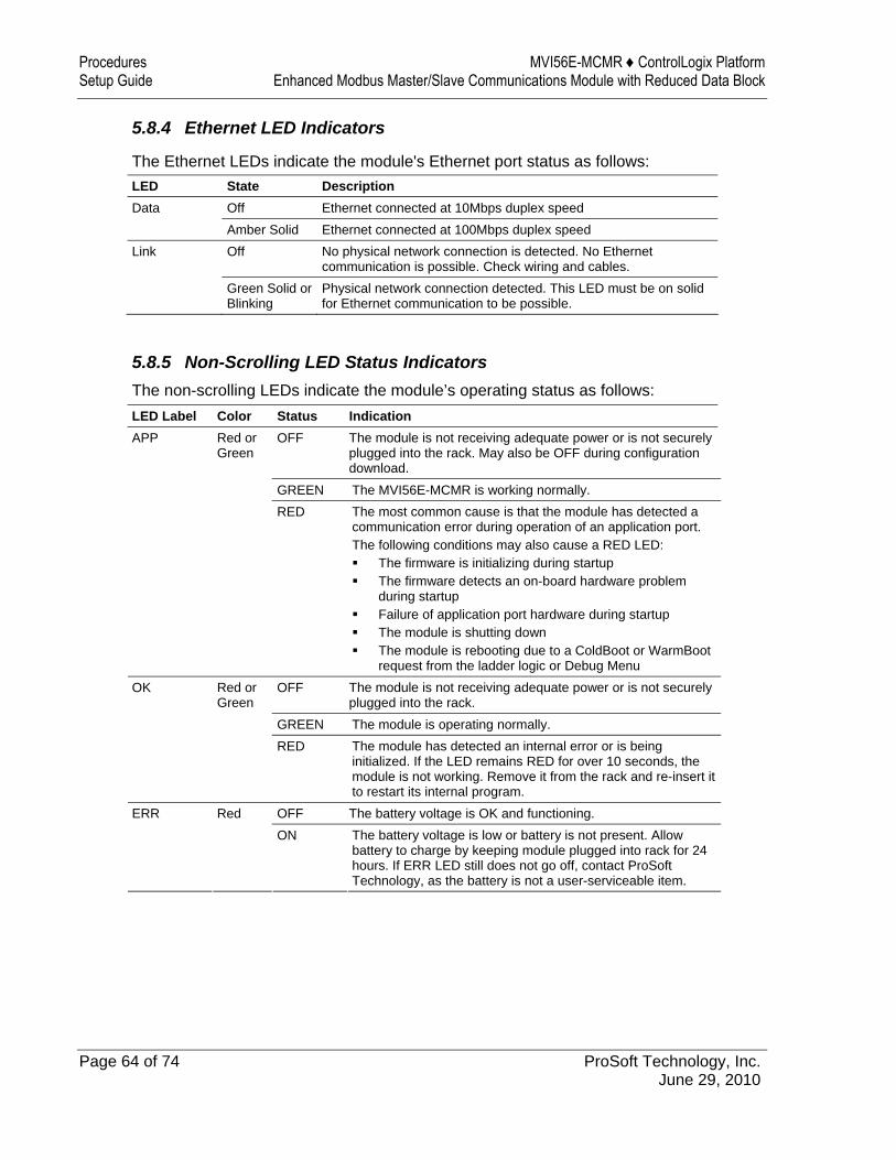
5.8.4 Ethernet LED Indicators
The Ethernet LEDs indicate the module's Ethernet port status as follows: LED State Description Data Off Ethernet connected at 10Mbps duplex speed Amber Solid Ethernet connected at 100Mbps duplex speed Link Off No physical network connection is detected. No Ethernet
communication is possible. Check wiring and cables. Green Solid or
Blinking Physical network connection detected. This LED must be on solid for Ethernet communication to be possible.
5.8.5 Non-Scrolling LED Status Indicators The non-scrolling LEDs indicate the module’s operating status as follows:
LED Label Color Status Indication OFF The module is not receiving adequate power or is not securely
plugged into the rack. May also be OFF during configuration download.
GREEN The MVI56E-MCMR is working normally.
APP Red or Green
RED The most common cause is that the module has detected a communication error during operation of an application port. The following conditions may also cause a RED LED: The firmware is initializing during startup The firmware detects an on-board hardware problem
during startup Failure of application port hardware during startup The module is shutting down The module is rebooting due to a ColdBoot or WarmBoot
request from the ladder logic or Debug Menu OFF The module is not receiving adequate power or is not securely
plugged into the rack. GREEN The module is operating normally.
OK Red or Green
RED The module has detected an internal error or is being initialized. If the LED remains RED for over 10 seconds, the module is not working. Remove it from the rack and re-insert it to restart its internal program.
OFF The battery voltage is OK and functioning. ERR Red ON The battery voltage is low or battery is not present. Allow
battery to charge by keeping module plugged into rack for 24 hours. If ERR LED still does not go off, contact ProSoft Technology, as the battery is not a user-serviceable item.
MVI56E-MCMR ♦ ControlLogix Platform Building on Success Enhanced Modbus Master/Slave Communications Module with Reduced Data Block Setup Guide
ProSoft Technology, Inc. Page 65 of 74 June 29, 2010
6 Building on Success
In This Chapter
Frequently Asked Questions .................................................................66
Now that you have successfully installed, configured, and verified operation of the MVI56E-MCMR module, you should have a better understanding of how to make it work for your specific application. The following resources are available to help you build on your success. For more information about the MVI56E-MCMR module, including detailed
hardware and software configuration, troubleshooting, and application information, refer to the MVI56E-MCMR User Manual.
For technical support and warranty information for your MVI56E-MCMR module, refer to Support, Service, and Warranty in the MVI56E-MCMR User Manual.
For more information on ProSoft Technology products and services, please visit www.prosoft-technology.com.
Building on Success MVI56E-MCMR ♦ ControlLogix Platform Setup Guide Enhanced Modbus Master/Slave Communications Module with Reduced Data Block
Page 66 of 74 ProSoft Technology, Inc. June 29, 2010
6.1 Frequently Asked Questions
6.1.1 What are the differences between the MVI56 and the MVI56E modules? What does the “E” stand for?
The "E" stands for Enhanced with Ethernet communication capabilities. The new enhancements are: PCB: MVI56E-MCMR products now use PCB (ProSoft Configuration Builder)
software, a Windows-based configuration utility providing a new graphic user interface for module diagnostics with screen navigation improving interoperability with the module.
Seamless Migration: MVI56E products are backward compatible with existing ladder logic and module configuration files allowing for a smooth "plug and play" transition when replacing the earlier version MVI56-MCMR product.
Personality Memory Module: The module incorporates a non-volatile CF memory card for storing the module’s configuration data (or personality). This feature benefits the end-user with quick replacement of faulted modules and restoration of systems by a simple exchange of the Personality Memory Module with absolutely no PC or configuration requirements.
Ethernet Configuration Port: Allows for remote module connectivity. Replaces serial communication port becoming the primary configuration port with a web server interface.
Web server: Provides HTML information about the status of the product and download access to documents and software such as the product manual and configuration software. Components are stored locally in the module’s flash memory.
LED Display: The LED provides additional detailed plain English diagnostic and error information for the module, backplane communication, and network conditions.
Discovery Service: Allows PCB configuration software (or separate utility) to find and display products located on the network with key product attributes such as name, serial number, and IP address. The user will be able to change IP address, upload/download, and enter into diagnostics from the list.
CIPconnect® enabled: Allows end-users to connect from remote locations to local and remote chassis installed MVI56E modules from anywhere.
6.1.2 Is the MVI56E product a direct replacement to my existing MVI56 product?
Yes
6.1.3 How is the MVI56E-MCMR configured? The module is configured with ProSoft Configuration Builder, which creates the necessary configuration files to download to the MVI56E-MCMR module.

MVI56E-MCMR ♦ ControlLogix Platform Building on Success Enhanced Modbus Master/Slave Communications Module with Reduced Data Block Setup Guide
ProSoft Technology, Inc. Page 67 of 74 June 29, 2010
6.1.4 What is ProSoft Configuration Builder (PCB)? ProSoft Configuration Builder (PCB) provides a quick and easy way to manage module diagnostics and troubleshooting operations. Built-in module diagnostics menus and the serial port data stream analyzer can be accessed using PCB through the module's high-speed Ethernet configuration port (E1) or though Rockwell Automation 1756-ENxT or 1756-CNBx communications interfaces using CIPconnect®.
6.1.5 What is the purpose of the MVI56E-MCMR Ethernet (E1) Port? The MVI56E-MCMR Ethernet Port (E1) allows a remote PC to configure and monitor the module operation through ProSoft Configuration Builder (PCB). The Ethernet Port (E1) is also used to set the module’s IP address. You can also set the IP address with ladder logic. Refer to the MVI56E-MCMR User Manual for more information on these tasks.
6.1.6 How do I change the module’s IP address? 1 Use ProSoft Configuration Builder to edit and download the Ethernet
configuration to the module. 2 Use the Optional Add-On Instruction (AOI) provided with the module. The
AOI can be downloaded from the module's web page.
6.1.7 Does the MVI56E-MCMR module require processor logic? Yes, ladder logic is required for data transfer between the MVI56E module and the ControlLogix® processor. For RSLogix™ 5000 version 16 applications (or later), the included Add-On
Instruction encapsulates the entire ladder logic into one single instruction. For RSLogix 5000 version 15 and older, sample ladder logic is available from
the ProSoft Technology® website at www.prosoft-technology.com.
Building on Success MVI56E-MCMR ♦ ControlLogix Platform Setup Guide Enhanced Modbus Master/Slave Communications Module with Reduced Data Block
Page 68 of 74 ProSoft Technology, Inc. June 29, 2010
6.1.8 What is the purpose of the Optional MVI56E-MCMR Add-On Instruction?
The Optional Add-On Instruction (AOI) allows the processor to perform the following tasks: 1 Set the MVI56E Ethernet settings 2 Read the MVI56E Ethernet settings 3 Set MVI56E date/time information 4 Read the MVI56E date/time information Items 1 and 2 can also be performed through ProSoft Configuration Builder (PCB) using ProSoft Discovery Service. Items 3 and 4 can also be performed through the module's built-in web page. The Optional AOI is needed only for specific applications where Ethernet or CIPconnect access from a programmer's personal computer (PC) to the module is not possible.
6.1.9 What is ProSoft Discovery Service (PDS)? ProSoft Discovery Service (PDS) is Windows-based software that connects to the Ethernet port of the module for the following purposes: Automatic module discovery on the Ethernet network Set a temporary IP address for the module for easy commissioning Allow PCB to select the module for monitoring and IP address reconfiguration
The ProSoft Discovery Service software is supplied as a stand-alone utility, as well as being integrated into PCB.
6.1.10 How do I monitor MVI56E-MCMR operation? Module operation can be monitored either through the processor controller tags or through the ProSoft Configuration Builder diagnostic window. Available status information includes number of messages sent, number of messages received, number of errors, and error codes.
6.1.11 Are there any other ways to monitor module diagnostics besides being connected to the module’s network (subnet)?
PCB can monitor the module via ControlLogix backplanes and process networks using CIPconnect. The PC running PCB can use its Ethernet port to connect to any 1756-ENxT EtherNet/IP™ interface module which is on the same Ethernet subnet. Through this connection, PCB can use CIPconnect to route through the ControlLogix backplane to other 1756-ENxT or 1756-CNBx modules, for up to five more route links, to reach an MVI56E module in a chassis connected on EtherNet/IP or ControlNet™ process networks.
MVI56E-MCMR ♦ ControlLogix Platform Glossary of Terms Enhanced Modbus Master/Slave Communications Module with Reduced Data Block Setup Guide
ProSoft Technology, Inc. Page 69 of 74 June 29, 2010
7 Glossary of Terms
A ASCII American Standard Code for Information Interchange. A communication mode in which each eight-bit byte in a message contains one ASCII character code. ASCII characters (or hexadecimal characters) are sometimes used as a key to encrypt data and ensure its secure transmission.
B Baud Rate The speed of communication between devices on the network. All devices must communicate at the same rate.
C Client A client is a software program, or the device on which that program runs, that makes requests for information from a software program, or the device on which that program runs, in a client-server relationship. A Client on an Ethernet network is equivalent to a Master on a serial network.
D Default Gateway The IP address of a network router where data is sent if the destination IP address is outside the local subnet. The gateway is the device that routes the traffic from the local area network to other networks such as the Internet.
E ESD Electrostatic Discharge. Can cause internal circuit damage to the coprocessor.
Ethernet A set of network cabling and network access (CSMA/CD) protocol standards for bus topology computer networks invented by Xerox but now controlled by the 802.3 subcommittee of the IEEE.
Glossary of Terms MVI56E-MCMR ♦ ControlLogix Platform Setup Guide Enhanced Modbus Master/Slave Communications Module with Reduced Data Block
Page 70 of 74 ProSoft Technology, Inc. June 29, 2010
F Firmware Software for embedded computers.
Full-Duplex A communications circuit or system designed to simultaneously transmit and receive two different streams of data. Telephones are an example of a full-duplex communication system. Both parties on a telephone conversation can talk and listen at the same time. If both talk at the same time, their two signals are not corrupted.
H Half-Duplex A communications circuit or system designed to transmit and receive data, but not both simultaneously. CB or walkie-talkie radios are an example of a half-duplex communication system. Either parties on a radio conversation may talk or listen; but both cannot talk at the same time without corrupting each other's signal. If one operator is "talking", the other must be "listening" to have successful communication.
I IP Address A 32-bit identification number for each node on an Internet Protocol network. These addresses are represented as four sets of 8-bit numbers (numbers from 0 to 255), separated by periods ("dots"). Networks using the TCP/IP Protocol route messages based on the IP address of the destination. Each number can be 0 to 255. For example, 192.168.0.100 could be an IP address. Each node on the network must have a unique IP address.
L LED Light-emitting diode.
M MAC ID A hexadecimal number that uniquely identifies an Ethernet device.
MVI56E-MCMR ♦ ControlLogix Platform Glossary of Terms Enhanced Modbus Master/Slave Communications Module with Reduced Data Block Setup Guide
ProSoft Technology, Inc. Page 71 of 74 June 29, 2010
Master A Master is a device that makes requests for information from a software program, or the device on which that program runs, in a Master-Slave relationship. A Client on an Ethernet network is equivalent to a Master on a Serial network.
N Network A series of stations or nodes connected by some type of communication medium. A network may consist of a single link or multiple links.
Node An address or software location on the network.
P Peer-to-Peer A network relationship between devices where each device can send commands as a master or client, and respond to commands as a slave or server.
Power Supply Device that supplies electrical power to the I/O chassis containing the processor, coprocessor, or other modules.
Protocol The language or packaging of information that is transmitted between nodes on a network.
R RS-232 Recommended Standard 232; the standard for serial binary signals between DTE and DCE devices.
S Serial Data/Serial Data Transmission Data that is transferred one bit at a time. Serial data transmission involves changing a carrier signal line between two possible states to indicate a binary 0 or binary 1 value. Successive data bits are rapidly transmitted one after the other with a fixed time allowed for each bit. Data bits are usually grouped into "packets", which contain a specific amount of data bits, along with extra bits included to provide error-checking capability.
Glossary of Terms MVI56E-MCMR ♦ ControlLogix Platform Setup Guide Enhanced Modbus Master/Slave Communications Module with Reduced Data Block
Page 72 of 74 ProSoft Technology, Inc. June 29, 2010
Server A Server is a software program, or the device on which that program runs, that provides a specific kind of service to a Client software program, or the device on which that program runs, on an Ethernet network. A Server on an Ethernet network is equivalent to a Slave on a Serial network.
Simplex A communications circuit or system designed to either transmit data or receive data, but not both. Broadcast television is an example of simplex communication system. A television station sends a TV signal but cannot receive responses back from the television sets to which it is transmitting. The TV sets can receive the signal from the TV station but cannot transmit back to the station.
Slave A Slave is a software program, or the device on which that program runs, which provides a specific kind of service to a Master software program, or the device on which that program runs, on a serial network. A Slave on a Serial network is equivalent to a Server on an Ethernet network.
Subnet Mask A mask used to determine what subnet an IP address belongs to. An IP address has two components: the network address, and the host (node or device) address. For example, consider the IP address 150.215.017.009. Assuming this is part of a Class B network (with a subnet mask of 255.255.0.0), the first two numbers (150.215) represent the Class B network address, and the second two numbers (017.009) identify a particular host on this network.
MVI56E-MCMR ♦ ControlLogix Platform Glossary of Terms Enhanced Modbus Master/Slave Communications Module with Reduced Data Block Setup Guide
ProSoft Technology, Inc. Page 73 of 74 June 29, 2010
Index
A About the MODBUS Protocol • 17 Architecture • 20 Are there any other ways to monitor module
diagnostics besides being connected to the module’s network (subnet)? • 68
ASCII • 69
B Battery Life Advisory • 3 Baud Rate • 69 Before You Begin • 11 Building on Success • 65
C Check Module Status through ControlLogix Controller
Tags • 61 Check Read Data • 60 Check Write Data • 59 CIPconnect • 32 Client • 69 Configure the Modbus Master Read Command • 19,
52 Configure the Modbus Master Write Command • 19, 53 Configure the Quantum Processor as a Modbus Slave
• 8, 19, 56 Connect the MVI56E-MCMR Module to the Quantum
Processor • 57 Connect to the Module's Web Page • 34 Connect your PC to the ControlLogix Processor • 19,
46 Connect Your PC to the Module's Ethernet Port • 25 Create a new RSLogix 5000 project • 19, 37 Create the Module - Remote Rack • 40 Create the Remote Network • 38
D Default Gateway • 69 Does the MVI56E-MCMR module require processor
logic? • 67 Download the Project to the Module • 54 Download the Sample Program to the Processor • 8,
19, 47
E Enable the Port 1 Master Commands • 8, 51 ESD • 69 Ethernet • 69 Ethernet LED Indicators • 64
F Firmware • 70 Frequently Asked Questions • 66 Full-Duplex • 70
G General Overview • 18
H Half-Duplex • 70 How do I change the module’s IP address? • 67 How do I monitor MVI56E-MCMR operation? • 68 How is the MVI56E-MCMR configured? • 66
I Import the Ladder Rung • 42 Important Safety Information - MVI56E Modules • 2 Install ProSoft Discovery Service • 15 Install the Configuration Tools • 8, 15 Install the Module in the Remote Rack • 24 IP Address • 70 Is the MVI56E product a direct replacement to my
existing MVI56 product? • 66
L Learning Objectives • 8 LED • 70
M MAC ID • 70 Master • 71 Memory Map • 21
N Network • 71 Node • 71 Non-Scrolling LED Status Indicators • 64
P Peer-to-Peer • 71 Physical Setup • 8, 19, 23 Power Supply • 71 Prerequisites • 10 Procedures • 23 ProSoft Technology Documentation • 9 ProSoft Technology® Product Documentation • 3 Protocol • 71
R Required Items • 12 Required Steps • 19 RS-232 • 71
S Sample Files • 13
Glossary of Terms MVI56E-MCMR ♦ ControlLogix Platform Setup Guide Enhanced Modbus Master/Slave Communications Module with Reduced Data Block
Page 74 of 74 ProSoft Technology, Inc. June 29, 2010
Scope • 7 Scrolling LED Status Indicators • 63 Serial Data/Serial Data Transmission • 71 Server • 72 Set Module Jumpers • 23 Set Temporary IP Address • 26, 35 Simplex • 72 Slave • 72 Subnet Mask • 72 System Requirements • 11
T The Sample Application • 8, 17
U Upload the Add-On Instruction from the Module • 36,
43 Upload the Sample Configuration from the Module • 48 Using ProSoft Configuration Builder Software • 48
V Verify Communication • 8, 19, 58 View Exchanged Data • 58
W What are the differences between the MVI56 and the
MVI56E modules? What does the • 66 What is ProSoft Configuration Builder (PCB)? • 67 What is ProSoft Discovery Service (PDS)? • 68 What is the purpose of the MVI56E-MCMR Ethernet
(E1) Port? • 67 What is the purpose of the Optional MVI56E-MCMR
Add-On Instruction? • 68 What’s New? • 7
Y Your Feedback Please • 4