munmorah power station · as with the nearby vales point power station, munmorah was orientated...
TRANSCRIPT

MUNMORAH POWER STATION TUGGERAH LAKES, N.S.W
Nomination for Award of Historic Engineering Marker
Prepared for
Engineering Heritage Australia (Newcastle)

1 | P a g e
Cover photograph: Munmorah Power Station at Night, 3 February 1970 - (ECNSW 09286)

2 | P a g e
Preface Frank Brady, a former Vice-Chairman, Chairman and General Manager of the Electricity
Commission of New South Wales (ECNSW), suggested that heritage is generally linked to
physical objects.1 In the legal system, for example, heritage can be seen in the profession’s
treasures or the headwear and gowns that judges and barristers wear. Likewise, legal heritage
also encompasses the Rule of Law, the Australian Constitution, former prominent legal
luminaries and the jury system. In the same way, the heritage of the power generation industry
extends beyond gleaming vertical reciprocating steam engines, marble-floored control rooms,
or large complex thermal power stations. The industry’s social impact; a specific piece of
infrastructure’s bearing on its local environment; the rarity of a piece of infrastructure; or the
degree to which it represents the industry or a particular era, are also encompassed by the term
heritage.
The New South Wales (NSW) electricity system embodies the fundamental infrastructure
of the State’s modern society. This statewide machine of power stations, transmission and
distribution networks reaches into nearly every home, office, shop, factory, and institution. It
is the largest single machine in the State. It encompasses many power stations using a range of
fuels and technologies. Thousands of kilometers of transmission lines and distribution
networks transport electricity to consumers. It is also the State’s most expensive infrastructure
investment albeit over many decades.
Munmorah was the second (after Vales Point) major power station designed and
commissioned by the Electricity Commission of New South Wales following its formation in
May 1950. The first of its four generating units was commissioned in February 1967. At that
time its 350 MW units were the largest on the NSW network. From 1969, Munmorah was the
Electricity Commission’s largest power station until Liddell’s third 500 MW unit was
commissioned in 1972.
Munmorah, as with each of the Electricity Commission’s new power stations incorporated
many new and innovative technologies - many being firsts for the organisation, the state and
nationally. However, the all-electric analog combustion and generation control system set the
station apart from its Electricity Commission, and national predecessors. This control concept
was the forerunner of control systems in future NSW and Australian power stations.
This document details the information required by Engineers Australia Guide to Engineering
Heritage Recognition Program (2012).
The accompanying document, ‘The New South Wales Electricity System’ outlines the history
of the State’s high-voltage electricity system as operated by the ECNSW between 1950 and
2003. This document expands on the engineering heritage of a single physical object, by
presenting background information on the NSW bulk electricity generation and transmission
industry. This information may also be used as background information to subsequent
applications for other power stations or infrastructure operated by these organisations. Equally,
this information could form the basis for engineering heritage recognition of the NSW
electricity system itself.
1 Alan Deans, "Frank Brady", Australian Business, 1 April 1982.
3 | P a g e
Acknowledgements The author wish to acknowledge the following people and organisations for their invaluable
help in the research for this application.
Rod Caldwell for the initial idea to apply for an engineering heritage award for the station.
Many former colleagues of the Electricity Commission of New South Wales, Pacific Power,
and Delta Electricity, who gave of their time, expertise in the form of one-on-one interviews
and the loan or gift of photographs, documents or memorabilia.
Heritage consultants C and MJ Doring and in particular their 1992 publication Vales Point
"A" Power station Heritage Study 1959 to 1989.
'Munmorah Power Station' in Mark Fetscher's self-published 2001 The Power Makers.
Unless otherwise stated, the State Records Authority of New South Wales is acknowledged
as the copyright owners of images from the Photographic Collection of the Electricity
Commission of NSW / Pacific Power 1950-94 (NRS 20347).
Generator Property Management Pty. Limited, the current managers of Munmorah site, for
their assistance in accessing Munmorah’s documentation archive.
A significant portion of this application, and the accompanying The New South Wales
Electricity System, was sourced from the author’s 2015 Ph.D. thesis "The Electricity
Commission of New South Wales and its place in the rise of centralised coordination of bulk
electricity generation and transmission 1888-2003,"
Finally, all errors and omissions of fact are the author’s.
Ken Thornton
April 2017
___________________________

4 | P a g e
PREFACE ........................................................................................................................... 2
ACKNOWLEDGEMENTS ................................................................................................ 3
MUNMORAH POWER STATION HERITAGE ASSESSMENT ................................... 6
Basic Data ........................................................................................................................................................ 6 Item Name: .................................................................................................................................................. 6 Location (grid reference if possible): ............................................................................................................. 6 Address: ....................................................................................................................................................... 6 Suburb/Nearest Town: ................................................................................................................................. 7 State: ........................................................................................................................................................... 7 Local Govt. Area: .......................................................................................................................................... 7 Owner: ......................................................................................................................................................... 7 Current Use: ................................................................................................................................................. 7 Former Use:.................................................................................................................................................. 7 Timeline: ...................................................................................................................................................... 7 Designer: ...................................................................................................................................................... 8 Major Equipment: ........................................................................................................................................ 8
Physical Description: ........................................................................................................................................ 8 Station Layout .............................................................................................................................................. 8 Coal Supply ................................................................................................................................................... 8 Cooling Water .............................................................................................................................................. 9 Boiler ........................................................................................................................................................... 9 Ash and Dust Plant ..................................................................................................................................... 12 Turbine - Generator .................................................................................................................................... 13 Electrical....................................................................................................................................................... 1 Control ......................................................................................................................................................... 1 Computer ..................................................................................................................................................... 2 Transmission ................................................................................................................................................ 2
Physical Condition: .......................................................................................................................................... 2
Modifications and Dates: ................................................................................................................................. 2
Assessment of Significance .............................................................................................................................. 3 Historical Significance: .................................................................................................................................. 3 Creative or Technical Achievement: .............................................................................................................. 3
All Electric Control System ........................................................................................................................ 3 Computer ................................................................................................................................................. 8 Plasma Ignition ....................................................................................................................................... 10 Carbon Capture Pilot Plant ...................................................................................................................... 11
Social and community:................................................................................................................................ 12 Components ............................................................................................................................................... 12 Integrity/Intactness: ................................................................................................................................... 13
Statement of Significance: ............................................................................................................................. 13 Area of Significance .................................................................................................................................... 13
Image(s) with caption: ................................................................................................................................... 14
Appendix 1 Boiler Performance Data at Continuous Rating ........................................................................... 21
Appendix 2 – Performance Statistics .............................................................................................................. 22
5 | P a g e
Appendix 3 Generating Plant installed in power stations operated by the Electricity Commission of New South Wales: May 1950, 30 June 1980 and 30 June 1994. .............................................................................. 23
Appendix 4 Burra Charter and the Heritage Assessment of NSW Power Stations ......................................... 29
BIBLIOGRAPHY ............................................................................................................. 30
Table of Figures
Figure 1 Artist's impression of Munmorah – 1966 (ECNSW 04425) ..................................... 6 Figure 2 Cross section of Munmorah Boiler (Courtesy Jim Nagle) ...................................... 10
Figure 3 3D view of Munmorah boiler (coutrtey Jim Nagle)................................................ 11 Figure 4 Pre Munmorah Combustion and Generation Control ............................................... 4
Figure 5 Direct Energy Balance Control System.................................................................... 6 Figure 6 Unit Coordinating Assembly ................................................................................... 7
Figure 7 "Computer for Munmorah" Network JUne 1964 pp 5-6 ........................................... 9 Figure 8 Munmorah / CSIRO Carbon Capture Plant ............................................................ 11
Figure 9 Munmorah External - (ECNSW 09270) ................................................................. 14 Figure 10 Munmorah - March 1965 - (ECNSW 05457) ....................................................... 14
Figure 11 Munmorah Coal Storage Area - February 1967 (ECNSW 07044) ........................ 15 Figure 12 Installation of Munmorah Mural in Administration Building Foyer (ECNSW
07129)................................................................................................................................. 15 Figure 13 Munmorah for Opening Souvenir Book (ECNSW 09270) .................................... 16
Figure 14 Munmorah Turbine Hall for Opening Souvenir Book (ECNSW 09270) ............... 17 Figure 15 Munmorah Steam Piping for Opening Souvenir Book (ECNSW 09270) .............. 18
Figure 16 Munmorah 1/2 Plant Control Room for Opening Souvenir Book (ECNSW 09270)
........................................................................................................................................... 19
Figure 17 Munmorah Computer Equipment for Opening Souvenir Book (ECNSW 09270) .. 19 Figure 18 Unit 3 Turbine and Electrical Control Panels following upgrade in the early 1990s.
(Courtesy of …) .................................................................................................................. 20 Figure 19 NSW Power Station Thermal Efficiency 1952 - 20010 ........................................ 22

6 | P a g e
Figure 1 Artist's impression of Munmorah – 1966 (ECNSW 04425)
Munmorah Power Station Heritage Assessment Munmorah was approved for construction in February 1961. Its first 350 Megawatt (MW)
generating unit was synchronised in February 1967 and its last in October 1969. For three
years, at 1400 MW, it was the Electricity Commission’s premier power station. Liddell
assumed that role in December 1972 with the commissioning of its third 500 MW generating
unit. Munmorah’s last operating generating unit (#3) was decommissioned in August 2110
after forty-one years of service to the people of New South Wales. In 2017, Munmorah is
being demolished.
Basic Data
Item Name:
Munmorah Power Station
Other/Former Names:
N/A
Location (grid reference if possible):
33012'41"S 151032'31.78"E
Munmorah Power Station is situated near Doyalson, Lake Macquarie, New South Wales
Address:
Station Road, Colongra, NSW, 2262
7 | P a g e
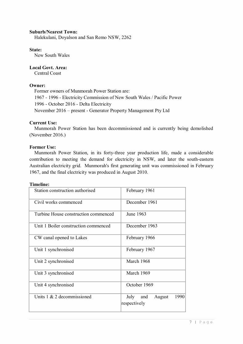
Suburb/Nearest Town:
Halekulani, Doyalson and San Remo NSW, 2262
State:
New South Wales
Local Govt. Area:
Central Coast
Owner:
Former owners of Munmorah Power Station are:
1967 - 1996 - Electricity Commission of New South Wales / Pacific Power
1996 - October 2016 - Delta Electricity
November 2016 – present - Generator Property Management Pty Ltd
Current Use:
Munmorah Power Station has been decommissioned and is currently being demolished
(November 2016.)
Former Use:
Munmorah Power Station, in its forty-three year production life, made a considerable
contribution to meeting the demand for electricity in NSW, and later the south-eastern
Australian electricity grid. Munmorah's first generating unit was commissioned in February
1967, and the final electricity was produced in August 2010.
Timeline:
Station construction authorised February 1961
Civil works commenced December 1961
Turbine House construction commenced June 1963
Unit 1 Boiler construction commenced December 1963
CW canal opened to Lakes February 1966
Unit 1 synchronised February 1967
Unit 2 synchronised March 1968
Unit 3 synchronised March 1969
Unit 4 synchronised October 1969
Units 1 & 2 decommissioned July and August 1990
respectively

8 | P a g e
Units 1 & 2 placed in storage 1991
Unit 3 placed on stand-by role 1998
Unit 4 placed in storage 1998
Unit 4 returned to service for period of time February 2000
Unit 4 last generation March 2009
Unit 3 last production August 2010
Designer:
Electricity Commission of New South Wales
Major Equipment:
Boilers International Combustion Australia Ltd.
Turbo-generators The English Electric Company of Australia Pty. Ltd.
Physical Description:
Munmorah produced electricity with bituminous coal as the primary fuel source. The basic
process used at Munmorah was identical to all Electricity Commission / Pacific Power
stations.2 Admittedly, there were differences in the type or manufacturer of various item of
plant and equipment, but the basic process did not differ.
Station Layout
As with the nearby Vales Point Power Station, Munmorah was orientated with its long axis
running south-west to north-east. Aesthetically, the visible aspect of Munmorah is similar to
the earlier Vales Point and later Liddell, Eraring, Bayswater and Mt Piper power stations.
Munmorah’s turbine hall is 270 metres long and thirty-five metres wide.
Two boiler structures each containing two 62-metre high boilers were to the immediate
south-east of the turbine hall with two 155-metre tall chimney stacks further to the south east.
Not including the ash disposal and associated coalmines the Munmorah site covered
approximately 570 hectares.
Coal Supply
Vales Point and Munmorah were constructed because of the Electricity Commission of New
South Wales's ongoing policy of locating major thermal power stations on the coalfields, at the
source of fuel. This meant considerably reduced fuel costs when compared with their load
2 Munmorah Power Station - Pamphlet, (Pacific Power, 1992-1996). 21. Electricity Commission of
New South Wales / Pacific Power Annual Reports 1953 - 2000: 1953 - 2001.
9 | P a g e
based predecessors. The Electricity Commission was thus able to generate electricity at
declining productions into the late 1960s and early 1970s.
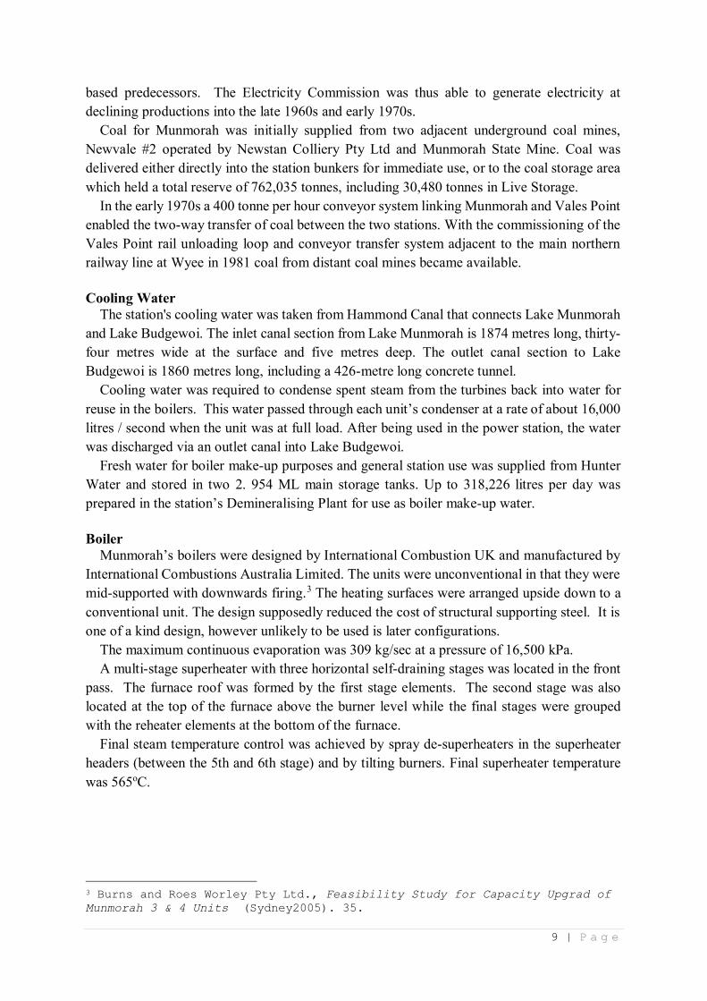
Coal for Munmorah was initially supplied from two adjacent underground coal mines,
Newvale #2 operated by Newstan Colliery Pty Ltd and Munmorah State Mine. Coal was
delivered either directly into the station bunkers for immediate use, or to the coal storage area
which held a total reserve of 762,035 tonnes, including 30,480 tonnes in Live Storage.
In the early 1970s a 400 tonne per hour conveyor system linking Munmorah and Vales Point
enabled the two-way transfer of coal between the two stations. With the commissioning of the
Vales Point rail unloading loop and conveyor transfer system adjacent to the main northern
railway line at Wyee in 1981 coal from distant coal mines became available.
Cooling Water
The station's cooling water was taken from Hammond Canal that connects Lake Munmorah
and Lake Budgewoi. The inlet canal section from Lake Munmorah is 1874 metres long, thirty-
four metres wide at the surface and five metres deep. The outlet canal section to Lake
Budgewoi is 1860 metres long, including a 426-metre long concrete tunnel.
Cooling water was required to condense spent steam from the turbines back into water for
reuse in the boilers. This water passed through each unit’s condenser at a rate of about 16,000
litres / second when the unit was at full load. After being used in the power station, the water
was discharged via an outlet canal into Lake Budgewoi.
Fresh water for boiler make-up purposes and general station use was supplied from Hunter
Water and stored in two 2. 954 ML main storage tanks. Up to 318,226 litres per day was
prepared in the station’s Demineralising Plant for use as boiler make-up water.
Boiler
Munmorah’s boilers were designed by International Combustion UK and manufactured by
International Combustions Australia Limited. The units were unconventional in that they were
mid-supported with downwards firing.3 The heating surfaces were arranged upside down to a
conventional unit. The design supposedly reduced the cost of structural supporting steel. It is
one of a kind design, however unlikely to be used is later configurations.
The maximum continuous evaporation was 309 kg/sec at a pressure of 16,500 kPa.
A multi-stage superheater with three horizontal self-draining stages was located in the front
pass. The furnace roof was formed by the first stage elements. The second stage was also
located at the top of the furnace above the burner level while the final stages were grouped
with the reheater elements at the bottom of the furnace.
Final steam temperature control was achieved by spray de-superheaters in the superheater
headers (between the 5th and 6th stage) and by tilting burners. Final superheater temperature
was 565oC.
3 Burns and Roes Worley Pty Ltd., Feasibility Study for Capacity Upgrad of
Munmorah 3 & 4 Units (Sydney2005). 35.

10 | P a g e
Figure 2 Cross section of Munmorah Boiler (Courtesy Jim Nagle)
11 | P a g e
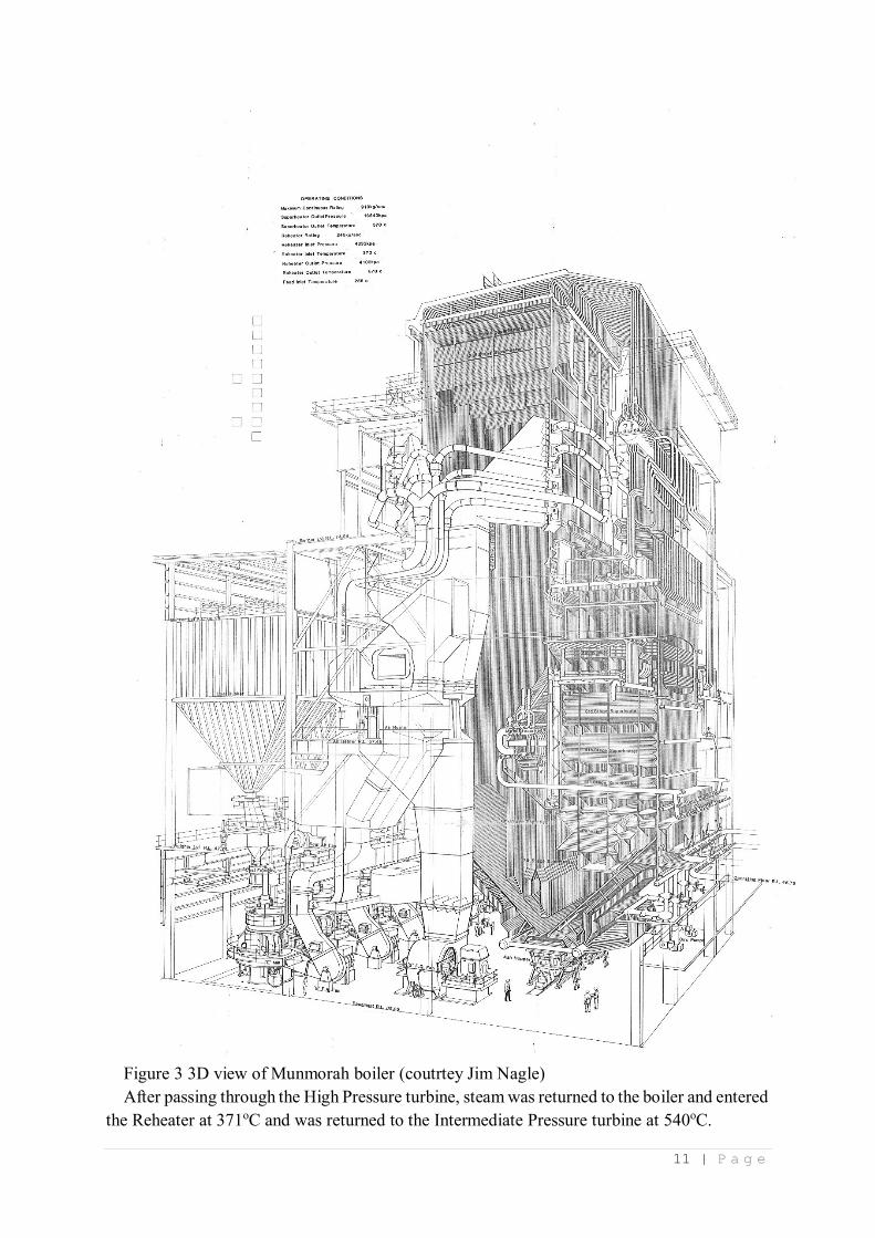
Figure 3 3D view of Munmorah boiler (coutrtey Jim Nagle)
After passing through the High Pressure turbine, steam was returned to the boiler and entered
the Reheater at 371oC and was returned to the Intermediate Pressure turbine at 540oC.

12 | P a g e
The Boiler Circulation Pumps were of the "canned" type in which the electric motor was
within the pump casing and immersed in boiler water at full boiler pressure. The Station's 1969
Opening Souvenir Book noted, "this type of pump was developed originally for nuclear power
stations and overcomes sealing difficulties encountered on conventional pumps where the
driving spindle enters the pump body. Four circulation pumps were provided for each boiler."4
The bolier’s combustion chamber was 56 metres high, eleven metres deep and 14 metres
wide.
Pulverised fuel entered the boiler's combustion chamber via corner-sited fuel burners. These
can be tilted up or down to control the combustion process.
Pulverising Fuel (PF) Mills
Before being admitted to the combustion chamber (furnance) coal was crushed to the
consistency of talcum powder in grinding mills. Each pulverising mill consumed
approximately 37.5 tonnes per hour.
The pulverising plant consisted of five "Lopulco" IM 45/3P, three roller, mills with
associated primary and sealing-air fans and table type coal feeders. The mills were of the
pressure type having a primary air fan located ahead of each mill to provide air for transporting
pulverised coal from the mill to the furnace. Of the five mills provided on each boiler, four
mills were capable of maintaining full boiler load. The fifth mill was available as a standby to
permit replacement of worn grinding parts without reduction in load on the boiler.
Fans
Induced Draft: each unit had two.
Forced draft: each unit had two.
Primary Air: each PF mill had one.
Boiler Feed Pumps
Each boiler had two 50% duty electrically driven feed pumps, and one 100% duty bled steam
turbine driven feed pump.
Ash and Dust Plant
The Ash and Dust Plant was designed to remove a maximum of 100 tonnes of ash per hour,
and a maximum of 145 tonnes of dust per hour.5
Electrostatic Precipitators were initially installed on all units. The Station's 1969 Opening
Souvenir Book noted, "experience at Commission's power stations has shown that larger
electrostatic precipitators than those usually found necessary in Britain and the United States
are needed to collect the dust from the flue gases produced when burning N.S.W. coals. The
design information used in determining the precipitator size was based on earlier pilot plant
testing and experience gained with electrostatic precipitators at the Commission's other power
stations. The dust collecting plant at Munmorah consists solely of electrostatic precipitators
operating at about 40,000 volts direct current. The precipitators collect more than 99 per cent
of the dust in the flue gases and the stack emission was well within the Clean Air Act
requirements.”6
4 Munmorah Power Station - Souvenir Opening Book, EC.061 (Sydney: Electricity Commission of
New South Wales, 1969). 22. 5 "Munmorah Power Station - Souvenir Opening Book," 27. 6 "Munmorah Power Station - Souvenir Opening Book," 26.
13 | P a g e
Fabric Filter Dust Collection plant was installed on Units 3 and 4 as part of a major upgrade
in the late 1980s / early 1990s.
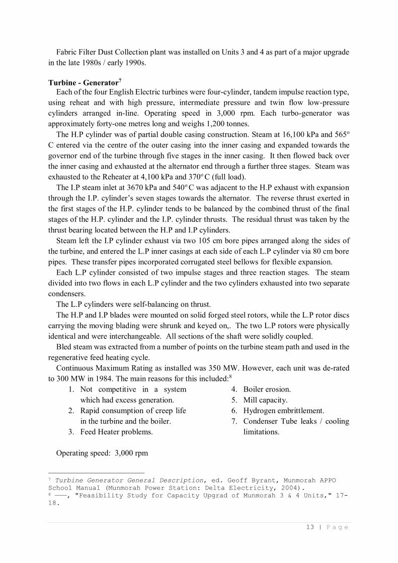
Turbine - Generator7
Each of the four English Electric turbines were four-cylinder, tandem impulse reaction type,
using reheat and with high pressure, intermediate pressure and twin flow low-pressure
cylinders arranged in-line. Operating speed in 3,000 rpm. Each turbo-generator was
approximately forty-one metres long and weighs 1,200 tonnes.
The H.P cylinder was of partial double casing construction. Steam at 16,100 kPa and 565o
C entered via the centre of the outer casing into the inner casing and expanded towards the
governor end of the turbine through five stages in the inner casing. It then flowed back over
the inner casing and exhausted at the alternator end through a further three stages. Steam was
exhausted to the Reheater at 4,100 kPa and 370o C (full load).
The I.P steam inlet at 3670 kPa and 540o C was adjacent to the H.P exhaust with expansion
through the I.P. cylinder’s seven stages towards the alternator. The reverse thrust exerted in
the first stages of the H.P. cylinder tends to be balanced by the combined thrust of the final
stages of the H.P. cylinder and the I.P. cylinder thrusts. The residual thrust was taken by the
thrust bearing located between the H.P and I.P cylinders.
Steam left the I.P cylinder exhaust via two 105 cm bore pipes arranged along the sides of
the turbine, and entered the L.P inner casings at each side of each L.P cylinder via 80 cm bore
pipes. These transfer pipes incorporated corrugated steel bellows for flexible expansion.
Each L.P cylinder consisted of two impulse stages and three reaction stages. The steam
divided into two flows in each L.P cylinder and the two cylinders exhausted into two separate
condensers.
The L.P cylinders were self-balancing on thrust.
The H.P and I.P blades were mounted on solid forged steel rotors, while the L.P rotor discs
carrying the moving blading were shrunk and keyed on,. The two L.P rotors were physically
identical and were interchangeable. All sections of the shaft were solidly coupled.
Bled steam was extracted from a number of points on the turbine steam path and used in the
regenerative feed heating cycle.
Continuous Maximum Rating as installed was 350 MW. However, each unit was de-rated
to 300 MW in 1984. The main reasons for this included:8
1. Not competitive in a system
which had excess generation.
2. Rapid consumption of creep life
in the turbine and the boiler.
3. Feed Heater problems.
4. Boiler erosion.
5. Mill capacity.
6. Hydrogen embrittlement.
7. Condenser Tube leaks / cooling
limitations.
Operating speed: 3,000 rpm
7 Turbine Generator General Description, ed. Geoff Byrant, Munmorah APPO
School Manual (Munmorah Power Station: Delta Electricity, 2004). 8 ———, "Feasibility Study for Capacity Upgrad of Munmorah 3 & 4 Units," 17-
18.
1 | P a g e
Voltage 17.5 kV
Current 12, 840 amps
Generator cooling:9
Stator: The windings of the generator are hollow and are directly cooled by distilled water
circulating through them. The water was taken to and from the windings by insulating hoses
and itself was cooled in external heat exchangers.
Rotor: The generator housing was filled with hydrogen gas at a pressure of 3 bar. Fans on
the generator rotor circulate hydrogen through ducts in the rotor and in the rotor windings. The
heat produced by the losses in these parts warms the hydrogen which was cooled by flowing
past nests of water-cooled tubes mounted within the generator casing.
Condensers
The twin Condensers on each unit had a cooling water flow of 772,835 litres per minute.
Two 0.894 MW Circulating Water Pumps per unit produce 408,011litres per minute
Chemical Control
Munmorah was the first ECNSW station to use a Feedwater Polishing Plant. These were
used during unit start-up to remove excess contaminates from the feedwater system
Electrical
330 kV switch yard
Provided for the connection of four 330 kV transmission lines, four generators and two
station transformers. The ‘11/2’ circuit breaker scheme was adopted - three circuit breakers
being used for each pair of main circuits consisting of a generator and a transmission line. The
330 kV circuit breaker were of the air blast type
Generator and main transformers
Three single phase 17.5/190 kV water-cooled on-load tap changing transformers forma 17.5
/ 330 kV 400 MVA 3 phase bank for each generator.
Auxiliary supply
Station transformers - two 80 MVA 330.33 Kv on-load tap changing supplying 33 kV to the
mines sub-stations and to 34 MVA 33/11/3.3 kV station auxiliary transformers.
Unit Auxiliary transformers - four 25 MVA 17.5 / 11 kV
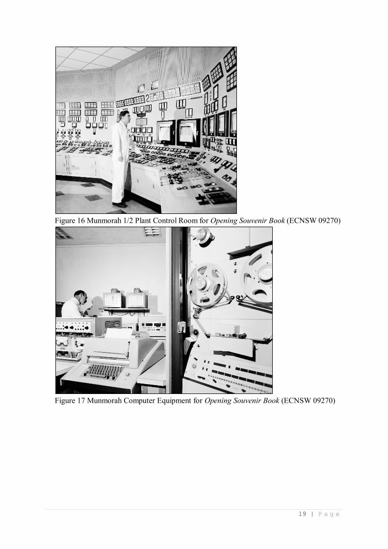
Control
Munmorah was the EC's first power station to utilise an all-electric rather than pneumatic
operated boiler-turbine control system.
Two plant control rooms between the turbine house and boilers are each equipped for the
remote starting and control of two boilers, the remote control of two turbines, and the remote
control of coal supplies to boilers and the supervision of ash and dust plant. The remote control
of the switchyard was carried out from No. 1 plant control room. The control system for each
boiler-turbine unit was of the all-electric type using electrical transmission of signals from
plant and electric actuators which moved valves, dampers and regulators to adjust flows,
temperatures and pressures on the plant in order to maintain the required conditions. The
control system worked on the direct energy balance principle in which a variation in the
generated output was balanced by a corresponding variation in the fuel and combustion air
9 "Munmorah Power Station - Souvenir Opening Book," 30.
2 | P a g e
input to the boiler. The system also controled a number of auxiliary automatic controls
regulating other quantities within the boiler turbine plant such as steam temperatures and
pressures, feedwater supply and water level in feedwater heaters. A detailed description of the
control system can be found at ‘Creative or Technical Achievement.’
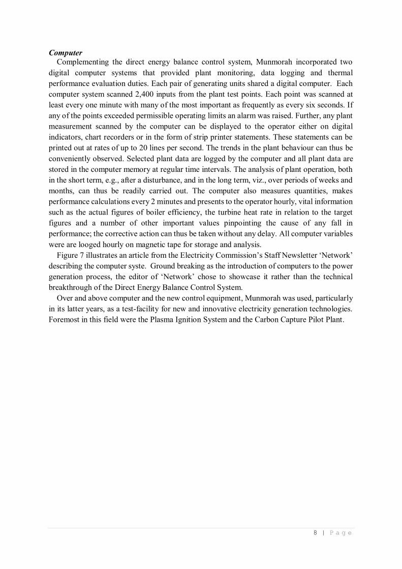
Computer
Two digital computer systems were provided, one for each pair boiler-turbine units, for plant
monitoring, data logging and thermal performance evaluation duties. Each computer system
constantly scaned 2,400 inputs from the plant test points. Each point was scanned every two
minutes and some scanned as frequently as every six seconds. If any point exceeded
permissible operating limits, an alarm was raised. Further, any of the plant measurements
scanned by the computer could be displayed to the operator either on digital indicators, on
chart recorders or in the form of typewritten statements. These statements were printed out at
rates of up to 20 lines per second. Trends in plant behaviour could thus be conveniently
observed. The computer loged selected plant data and all plant data were stored in the
computer’s memory at regular time intervals. The analysis of plant operation, both in the short
term, e.g., after a disturbance, and in the long term, viz., over periods of weeks and months,
could be readily carried out. The computer also measured quantities, made calculations and
presented vital information such as the actual figures of boiler efficiency, the turbine heat rate
in relation to the target figures and a number of other important values pinpointing the cause
of any fall in performance; the apporpriate corrective action can thus be taken without any
delay.
Transmission
The output of each of Munmorah's generators was fed into a 330kV switchyard via step-up
transformers. Here electricity was fed into three 330kV transmission lines. Two were
connected to Sydney and a third to nearby Vales Point Power Station.
Physical Condition:
The power station is being demolished
Modifications and Dates:
Plant Life Extension 1988 - 1992
Munmorah's Plant Life Extension regime allowed the Station to continue operation through
to 2010 and be available until 2012 – i.e. 45 years of operation, or greater than 50 years since
design.
In the 1960's, the design life for major power station components was specified as 25 years.
This was the framework for Vales Point 'A', Munmorah, Liddell and possibley Vales Point 'B'.
There was a targeted Plant Life Extension philosophy applied to Munmorah and Liddell. In
1986 John Marcheff and Bob Porter were sent on a fact-finding trip to the U.K. to talk to the
Central Electricity Generating Board (CEGB), English Electric and Parsons on measures
required to extend the life of the generating assets (and turbo-generators in particular) out to
50 years.
Between 1988 and 1992, a structured programme of Plant Life Extension on the Munmorah
Units was implemented. This included an Environmental Upgrade, and other similar elements.
3 | P a g e
The Leeds and Northrup Direct Energy Balance control system was replaced by the Bailey
Network 90 system. While both control systems were electrical / electronic rather than
pneumatic, the main difference was that the later system was digital rather than analog.
The capital budget over those years was more than $200 million.
The importance of the overall plant extension project was somewhat diluted by the dramatic
generation over-supply scenario that prevailed within Pacific Power (and elsewhere throughout
south-east Australia) in the mid-1980s and early1990s. Over-supply resulted in the 660 MW
units at Mount Piper being mothballed for two or three years before being commissioned in
1992 and 1993. By this time, Munmorah Units 1 and 2 had been placed in long-term storage
and saw very little, if any generation thereafter.
Assessment of Significance
Historical Significance:
Munmorah’s heritage significance derives from the first use in NSW and Australian power
stations of an all-electric, rather than pneumatic, operated, boiler-turbine control system.
Equally important, Munmorah was the first to use computers in monitoring the production
process.
The plant is significant because it was an example of large base-load thermal power
generation plant. With the commissioning of the first of the 350 MW units at Munmorah, in
February 1967, it became the largest on the NSW network until the first 500 MW unit at Liddell
(#2) came online in May 1971. With the commissioning of Munmorah #3, the station became
the largest power station in NSW exceeding Vales Point A’s 875 MW. Munmorah retained
the EC’s premier station until Liddell’s third 500 MW unit was synchronised in December
1972.
Creative or Technical Achievement:
All Electric Control System
Before describing the combustion and generation control system (direct energy balance
control system (DEB)) installed at Munmorah, a review is warranted of the then conventional
method of controlling the electricity generation processes. This will contribute to a greater
appreciation of why Munmorah’s control system is so significant in the history of NSW power
stations.
In earlier power stations, the various processes that contributed to the final output of
electrical energy were conceived as separate entities – boiler plant; turbine plant; coal handling,
and ash and dust.10 The boiler operator’s role was to supply steam to the station’s common
steam receiving system. His plant used coal supplied by the coal plant operator. The turbine
operator’s role was to ensure that the turbine operated at constant speed using steam taken from
the station’s common steam system. The electrical control room operator was concerned with
generation output, voltage control and the distribution of electrical energy to local networks.
Over many decades, individual control centres became more complex as improved
instrumentation, alarm systems and plant controls were installed. Wangi A was one, if not the
10 C Ayers, Campbell, C.L.,, "Automation in the Power Station," The
Australasian Engineer September 1965: 83.
4 | P a g e
last ECNSW power station to have separate individual control centres.11 Wangi B incorporated
a Plant Control Room were the boiler and turbine controls were in one location. The electrical
output controls for both A and B sections were in a single Electrical Control Room. Vales Point
A continued this centralising trend with all controls for Units 1 and 2 located in #1 Plant
Control Room, and those for Units 3 and 4 in #2 Plant Control Room. Munmorah and later
power station continued this trend.
Vales Point 1 to 4, despite their many innovations, including the first use of reheated steam
in Australia, represented the end of an era, at least in the philosophy of combustion and
generation control. These units and previous NSW power station’s incorporated analog
pneumatic systems for instrumentation and control of critical processes. In its simplest form,
compressed air was both the control medium and the power medium. Critical parameters, such as
actual steam pressure at the turbine stop valves, steam flow, fuel flow and air flow were derived
through pneumatic instrumentation. Fan dampers and other process actuators and regulators
were pneumatic controlled and driven.
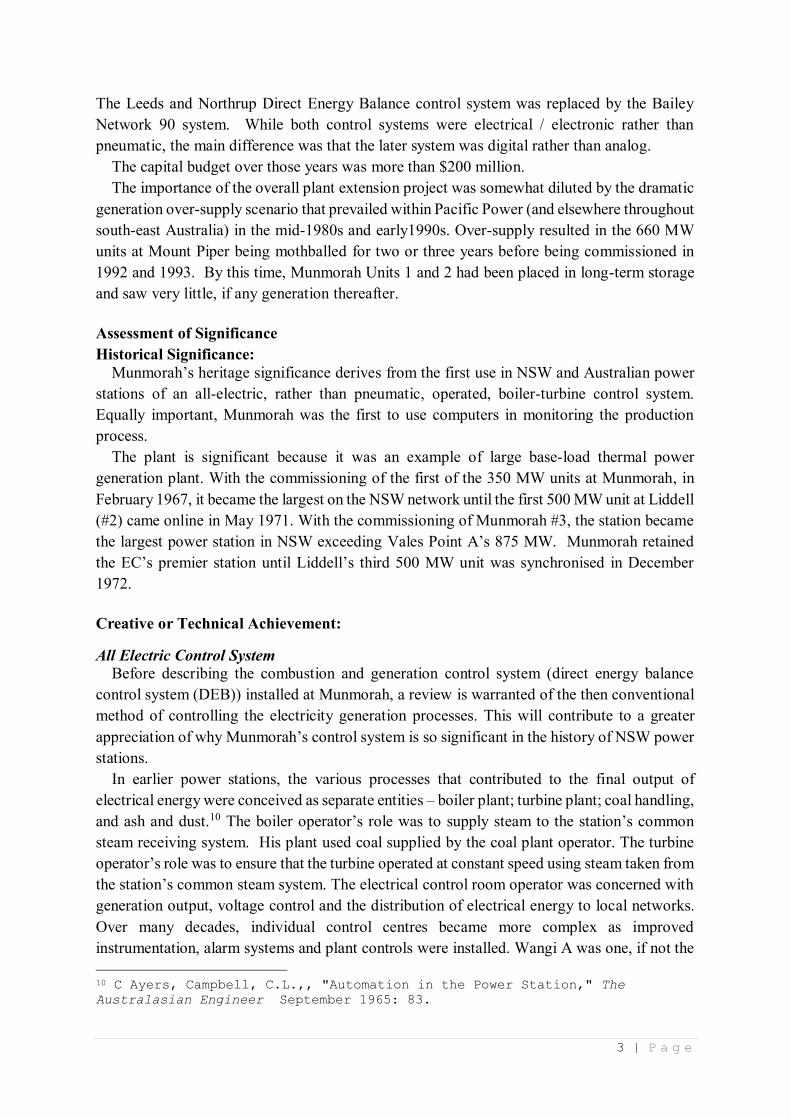
As illustrated in Figure 1, the crux of Vales Point A’s combustion control involved changes
in electrical output (MW) resulting in changes in steam pressure and steam flow.
Figure 4 Pre Munmorah Combustion and Generation Control12
Changes in steam pressure resulted in changes in fuel flow to the boiler, while changes in
steam flow resulted in changes in airflow. An inherent, if not the primary, characteristic of this
type of control system are process lags or time delays. For example, an increase in MW output
resulted in a subsequent fall in steam pressure at the turbine stop valves. This reduction in turn
has to be detected by pneumatic instrumentation and a pneumatic signal generated that became
an input in the Combustion Control system. In many respects this was a consequential or serial
control system. A change in a parameter had to be detected before a control signal was
generated to instruct the relevant process component to respond.
11 C. and M.J. Doring, Wangi Power Station Heritage Study (C. & M.J.
Doring Pty., 1990). 455-69. 12 The description of the Direct Energy Balance Control System relies
heavily on - K.F. Walker, "Analog Controls and digital Data Processing
Applied to Munmorah Power Station," The Australasian Engineer, no.
September 1965: 87-93.

5 | P a g e
As boilers increased in size to meet demands for higher steam pressures and temperatures
their pneumatic control systems were difficult to adapt to improved control strategies. Equally
important, in the early 1960s, electrical / electronic automatic load frequency control systems
had been installed in the systems of the State Electricity Commission of Victoria and Snowy
Mountains Hydro. Operational experience showed that the power station pneumatic control
systems were not sufficiently responsive or reliable to competently perform this automatic
function. Control system designers were also mindful that boiler input controls and generator
output controls inherently affect each other and in certain circumstances could produce cycling
of steam pressure and generator output.
To resolve control system responsiveness inherent in process lag and cycling issues, Leeds
and Northrup introduced their Direct Energy Balance control concept (DEB) to provide
coordination between adjustments to the turbine governor and the combustion control system.
Munmorah was the first Electricity Commission (and Australian) power station to utilise this
new all-electric concept.
This system had two primary components. The first, incorporated electrical, rather than
pneumatic, instrumentation to determine process parameters, and the transmission of control
signals to the plant and electric actuators used to move valves, dampers and regulators to adjust
flows, temperatures and pressures.
The second component, the DEB system itself, essentially operated on the principle that
irrespective of whether desired generation changes are initiated locally or remotely, the boiler
and turbine generator were adjusted simultaneously to obtain optimum performance.
Frequency bias, limits, runback and rate of change functions prevent desired generation
changes from exceeding the capabilities of the boiler, turbine and their auxiliaries. The direct
energy balance concept is illustrated in Figure 2. A desired generation signal is applied to the
boiler-turbine-governor component of the DEB control signal which produces a required
output signal that is within the capabilities of the boiler, turbine and auxiliaries. The required
output signal cannot be varied at a rate which exceeds a pre-set rate of change value except
under emergency conditions when runback actions will take place at an emergency rate of
change. Pre-set limits will also prevent the required output signal exceeding desired values.

6 | P a g e
Figure 5 Direct Energy Balance Control System
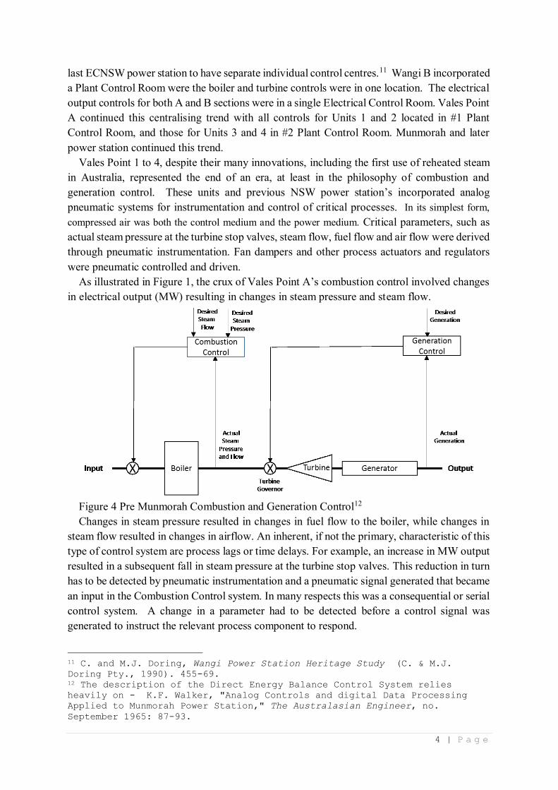
The required output signal and an actual generation signal are applied to the Unit
Coordinating component of the DEB control system, as are desired steam pressure and actual
steam pressure signals. The Unit Coordinating component (Figure 3) integrates the control
action of the Combustion control and governor control systems.
7 | P a g e
Figure 6 Unit Coordinating Assembly
Under normal conditions the required output from the boiler-turbine governor control
system will provide a control set point for the combustion control system and the governor
control system. Required output is also compared with actual generation and should a
difference exist then a generation initiated correction signal will be applied to both the
combustion and governor control systems. Steam pressure is compared with a manually
adjustable set point value and again if a difference exists then a pressure initiated correction
signal will be applied in parallel to the combustion and governor control systems.
Reference to Figure 6 indicates that the pressure initiated correction signal is added to the
generation initiated correction signal being applied to the combustion control system but is
subtracted from the same signal being applied to the governor control system. This
arrangement merely reflects the opposite effects which adjustments to fuel input and governor
action have on steam pressure. Whereas an increase in fuel input to the boiler increases steam
pressure an increase in governor setting decreases steam pressure and the reverse is true in
each case.
Apart from the DEB automatic control system described above, the Munmorah Operator
had three other modes of control available. These are Manual, Boiler Follow (Boiler Pressure
Control) and Turbine Follow (Base Load).
8 | P a g e
Computer
Complementing the direct energy balance control system, Munmorah incorporated two
digital computer systems that provided plant monitoring, data logging and thermal
performance evaluation duties. Each pair of generating units shared a digital computer. Each
computer system scanned 2,400 inputs from the plant test points. Each point was scanned at
least every one minute with many of the most important as frequently as every six seconds. If
any of the points exceeded permissible operating limits an alarm was raised. Further, any plant
measurement scanned by the computer can be displayed to the operator either on digital
indicators, chart recorders or in the form of strip printer statements. These statements can be
printed out at rates of up to 20 lines per second. The trends in the plant behaviour can thus be
conveniently observed. Selected plant data are logged by the computer and all plant data are
stored in the computer memory at regular time intervals. The analysis of plant operation, both
in the short term, e.g., after a disturbance, and in the long term, viz., over periods of weeks and
months, can thus be readily carried out. The computer also measures quantities, makes
performance calculations every 2 minutes and presents to the operator hourly, vital information
such as the actual figures of boiler efficiency, the turbine heat rate in relation to the target
figures and a number of other important values pinpointing the cause of any fall in
performance; the corrective action can thus be taken without any delay. All computer variables
were are looged hourly on magnetic tape for storage and analysis.
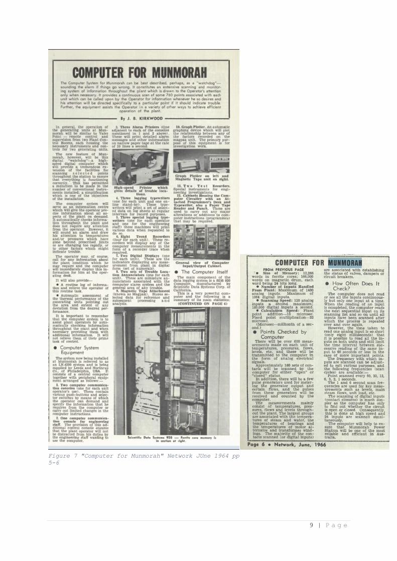
Figure 7 illustrates an article from the Electricity Commission’s Staff Newsletter ‘Network’
describing the computer syste. Ground breaking as the introduction of computers to the power
generation process, the editor of ‘Network’ chose to showcase it rather than the technical
breakthrough of the Direct Energy Balance Control System.
Over and above computer and the new control equipment, Munmorah was used, particularly
in its latter years, as a test-facility for new and innovative electricity generation technologies.
Foremost in this field were the Plasma Ignition System and the Carbon Capture Pilot Plant.
9 | P a g e
Figure 7 "Computer for Munmorah" Network JUne 1964 pp
5-6

10 | P a g e
Plasma Ignition
Pacific Power developed the Plasma Ignition System, first as a test facility at Wangi and
Wallerawang and then in the 1990s as a fully operational component at Munmorah. This
technology aimed to investigate the replacement of fuel oil or gas firing on pulverised coal
fired boilers.13 Traditionally, fuel oil and/or gas firing had been used for three purposes:
1. To bring the boiler into service from cold in a gradual and controlled manner;
2. To provide a source of ignition for the main pulverised coal burners;
3. To stabilise combustion during load changes and low load operation.
Munmorah’s Unit 3 was allocated to the Plasma Ignition System.14 The system included a
Fabric Filter unit to collect Pulverised Fuel (PF) from the Unit 3D Mill, a 120 tonne PF Storage
Silo, PF Injectors, a nitrogen sealing system. The single elevation of plasma guns were
positioned below the elevations of PF burners.
The plant designers were also mindful that the storage of large quantities of pulverised fuel
was not without inherent issues namely spontaneous combustion and gas explosions – both of
which did occur despite the nitrogen sealing system. The plant was used successfully over an
extended period of time, however, the capital expenditure costs, the plasma ignition electrics,
and boiler flame monitoring, were some large obstacles to overcome. It is understood that this
system was available until the station closed. Loads as low as 35 MW were achieved for
extended periods.15 Overall, the plasma system had a 70 MW load capacity with unit start-up
costs being miniscule compared to fuel oil.
The technology has been adopted by many Chinese authorities for both existing and new
boilers. energy-tech.com notes that:
Chinese installations focused on fuel oil displacement as a key feature of the technology.
Applications started with single elevation of existing oil-fired ignitors to be replaced with
plasma technology. One of many installations was demonstrated in 2006 at Huaneng Yuhuan
1,000 MW unit, where the technology was successful in system start-up from a cold start. The
ultimate application was to provide an oil free power plant, eliminating the fuel oil system,
using plasma technology for all elevations of ignitors on the boiler. The concept was
successfully demonstrated in 2008 at the new 2x600 MW Guodian Kangping Plant, where no
fuel oil system was included in the design. 16
13 P. Vierboom, Foreman, C.,, "Boiler Ignition Using Pulverised Coal"
(paper presented at the 1996 National Conference on Bulk Materials
Handling, Melbourne, 30 September 1996). Interviewee S, Personal
Communication with author, 27 January 2017. 14 Interviewee P, Personal Communication with author, 22 September 2016, 2
January 2017. 15 P. Vierboom, Hauck, C., Xie, Q.,, "Plasma ignition technology for
pulverized coal boilers : A competitive edge in pulverized coal power
generation," http://www.energy-tech.com/steam/article_777d4725-1b0b-530c-
a994-4d9251a7647e.html. [Accessed 28 January 2017]. 16 ———, "Plasma ignition technology for pulverized coal boilers : A
competitive edge in pulverized coal power generation" [Accessed 28 January
2017].

11 | P a g e
Carbon Capture Pilot Plant
The post-combustion Carbon Capture
Pilot Plant was a joint research project
between the Commonwealth Scientific
and Industrial Research Organisation
(CSIRO), the Department of Resources
and Energy and Delta Electricity. The
plant was supported through the Asia-
Pacific Partnership on Clean
Development and Climate.17 The plant
was commissioned in 2008 and the
research program commenced in
February 2009.
Post-combustion capture (PCC) was
the first stage in the process of carbon
dioxide capture and storage. Amine-based
liquid absorbents, including ammonia,
(which was used at Munmorah) capture
CO₂ and sulphur dioxide (SO2) from the
flue gases before it is emitted to the
atmosphere.
The pilot plant trials confirmed the
technical feasibility of the ammonia-
based capture process and some of
expected benefits. CO2 removal efficiency
of more than 85% was achieved.18 Although not carried out at Munmorah, the captured CO₂
product is pure enough that it is ready for compression, transport and storage.
The Munmorah Pilot Plant received flue gas from Unit 3 Induced Draft (ID) fan discharge
and discharged downstream into the stack intake. Unit 3 also provided steam to strip the
ammonia back out of the flue gas for reuse. The plant was capable of removing approximately
3,000T of CO2. Dependent on the success of trials geo-sequestration investigations, and
ongoing funding, a development plant capable of removing 100,000T was the next step
coupled with transport and storage trials at a selected site (Munmorah and Vales Point geology
was not suitable for substantial drilling field work). With the closure of Munmorah, the plant
was relocated to Vales Point. However, changed political and policy imperatives changed, and
funding was not forthcoming to progress the Vales Point trials.
17 Interviewee P, Personal Communication with author, 22 September 2016, 2
January 2017. Paul H.M. Feron, Assessing Post-Combustion Capture for Coal-
fired Power Stations in Asia-Pacifi c Partnership Countries: Final report to
the Department of Resources, Energy and Tourism (Newcastle: CSIRO Advanced
Coal Technology, 2012). 24. 18 ———, Assessing Post-Combustion Capture for Coal-fired Power Stations in
Asia-Pacifi c Partnership Countries: Final report to the Department of
Resources, Energy and Tourism: 30.
Figure 8 Munmorah / CSIRO Carbon Capture Plant
12 | P a g e
Social and community:
Many of the people who worked at Munmorah retain a fondness for the station and their
time there that in many instances was not evident at earlier or later Electricity Commission
power stations. Many people had been at the station from its earliest days and had established
an intangible relationship with the station. Defining and analysing this relationship, this
‘fondness,’ is a very subjective exercise. It cannot be defined in numerical terms; people often
use different words, or forms of expression to explain their relationship with the station and
their work colleagues.
Many of the people interviewed for this project and the companion 50th Anniversary history,
commented on Munmorah being a happy place to work; that there did not seem to be significant
division between workgroups or between employees and management. Equally important, the
employee Sports and Social Club was very strong and was actively supported by both
management and employees. Lunch-time sporting activities, such as Volley Ball and fun runs
contributed to a favourable workplace.
Two brief community related examples also provide an insight into the genesis of this regard
for the station. Both relate to non-work related aspects of Munmorah.
The first relates to Camp Breakaway, a not-for-profit chartable organisation located High
View Avenue, San Remo. Camp Breakaway was established in 1982 specialising in providing
respite care for people with disabilities and their carers.19. The Electricity Commission donated
a portion of Munmorah’s buffer zone to establish this facility.
The second relates to Koala Park that is located off the power station entrance road. Many
employees considered this facility as one of the benefits of their time at the station. As with
Camp Breakaway, Koala Park is located on power station land, but remained owned by the
station. Once the station closed in the early 2010s, the park was leased to Wyong Council for
99 years. In it hey-day, Koala Park was the venue for many of the station’s social events.
Most notable of these was the annual Children’s Christmas Party that was run by the
Munmorah Sports and Social Club. Koala Park was developed by the Sports and Social Club
with generous financial and in-kind assistance from the station’s management.
Rarity: n/a
Components
Components of Munmorah Power Station were mostly standard equipment for power
generation in the 1960s when the plant and equipment were ordered. Exceptions included:
Down-firing boiler: Unlike Vales Point A, Pulverised Fuel was admitted to the top of the
boiler’s combustion chamber. Further research is required to determine the background to the
decisions to install this configuration. All subsequent Electricity Commission power stations
utilised the standard bottom fired configuration
Representativeness:
Munmorah Power Station was representative of Electricity Commission of New South
Wales power stations commissioned between 1961 (Vales Point A) and the early 1970s
(Liddell). These power stations (200 MW to 500 MW) constitute the organisation first major
19 "Camp Breakaway - Overview," Camp Breakaway Inc.,
http://www.breakaway.org.au/about/overview. [Accessed 1 December 2016].
13 | P a g e
construction program. The second involved the commissioning of twelve 660 MW generating
units between 1978 and 1994.
Integrity/Intactness:
Munmorah Power Station is in the process of being demolished.
Statement of Significance:
The first generating unit at Munmorah Power Station was commissioned in February 1967,
the fourth and final unit in October 1969. The station was the Electricity Commission's
response to high single digit and in some year’s double-digit increase in the state's annual
demand for electricity. Munmorah along with the earlier Vales Point and the later Liddell and
Wallerawang C, constituted the Electricity Commission's first major power station
construction program.
While these three power stations utilised similar basic power generation technologies and
processes, Munmorah incorporated a number of engineering innovations. These included
down-fired boilers, all electric controls and computerised monitoring.
Throughout much of its four-decade productive life Munmorah provided reliable base load
service. In 1974, it contributed 23% of the total energy generated by NSW coal-fired power
stations during the year. As larger, more efficient power stations were commissioned
Munmorah's contribution declined.
While many ex-Munmorah employees have fond opinions of the station, it is important to
appraise its production record in the context of the state's demand for electricity, and the
production records of stations that preceded it as well as those commissioned after it. In the
context of The Electricity Commission's overall generation portfolio, Munmorah, while
contributing to the burgeoning demand for electricity was nevertheless relatively quickly
overtaken by Liddell as the organisation's premier power station. Munmorah's fourth 350 MW
unit was commissioned in October 1969 bringing the station's output to 1400 MW. Yet, three
years later in December 1972, Liddell's became the Commission's largest station with the
commissioning of a third 500 MW unit.23
Area of Significance
State.
23 Electricity Commission of New South Wales / Pacific Power Annual Reports 1953 - 2000.

14 | P a g e
Image(s) with caption:
Figure 9 Munmorah External - (ECNSW 09270)
Figure 10 Munmorah - March 1965 - (ECNSW 05457)
15 | P a g e
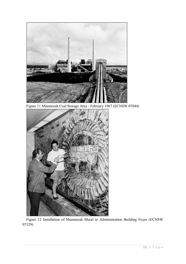
Figure 11 Munmorah Coal Storage Area - February 1967 (ECNSW 07044)
Figure 12 Installation of Munmorah Mural in Administration Building Foyer (ECNSW
07129)
16 | P a g e
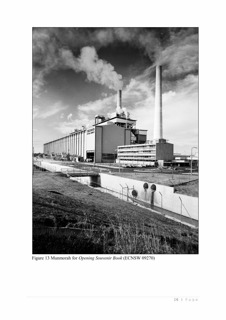
Figure 13 Munmorah for Opening Souvenir Book (ECNSW 09270)
17 | P a g e
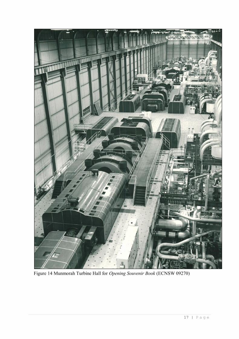
Figure 14 Munmorah Turbine Hall for Opening Souvenir Book (ECNSW 09270)
18 | P a g e
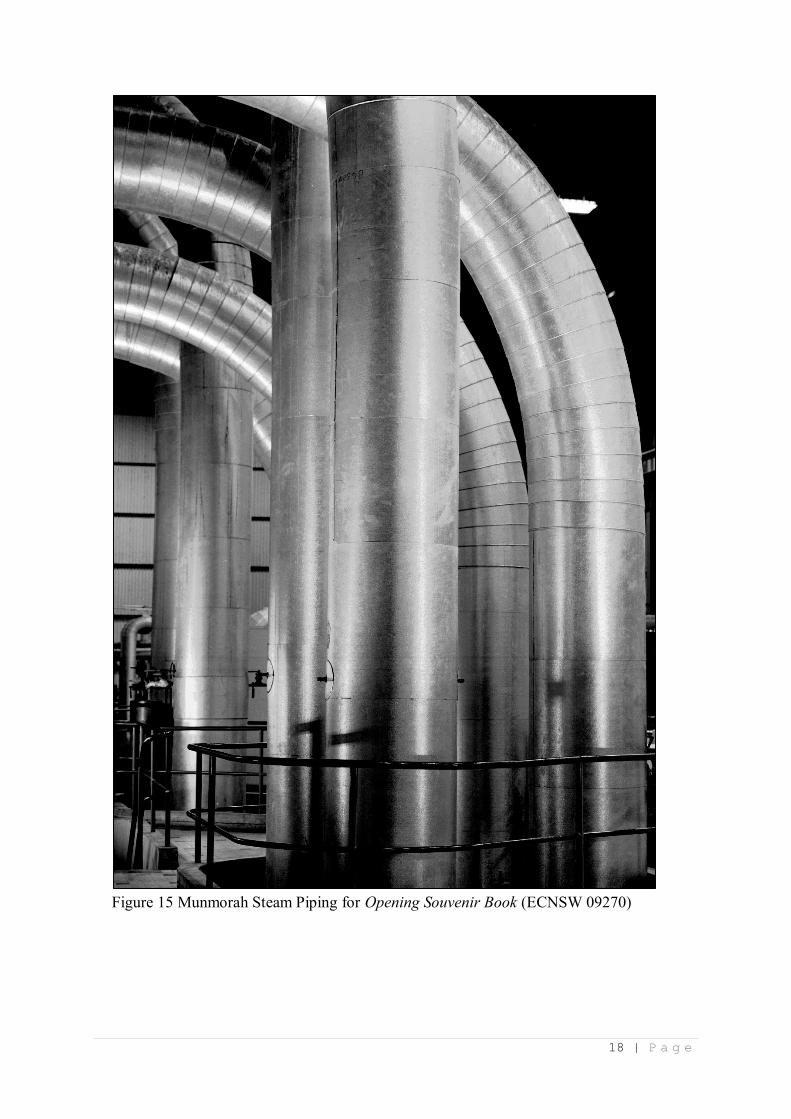
Figure 15 Munmorah Steam Piping for Opening Souvenir Book (ECNSW 09270)
19 | P a g e
Figure 16 Munmorah 1/2 Plant Control Room for Opening Souvenir Book (ECNSW 09270)
Figure 17 Munmorah Computer Equipment for Opening Souvenir Book (ECNSW 09270)
20 | P a g e
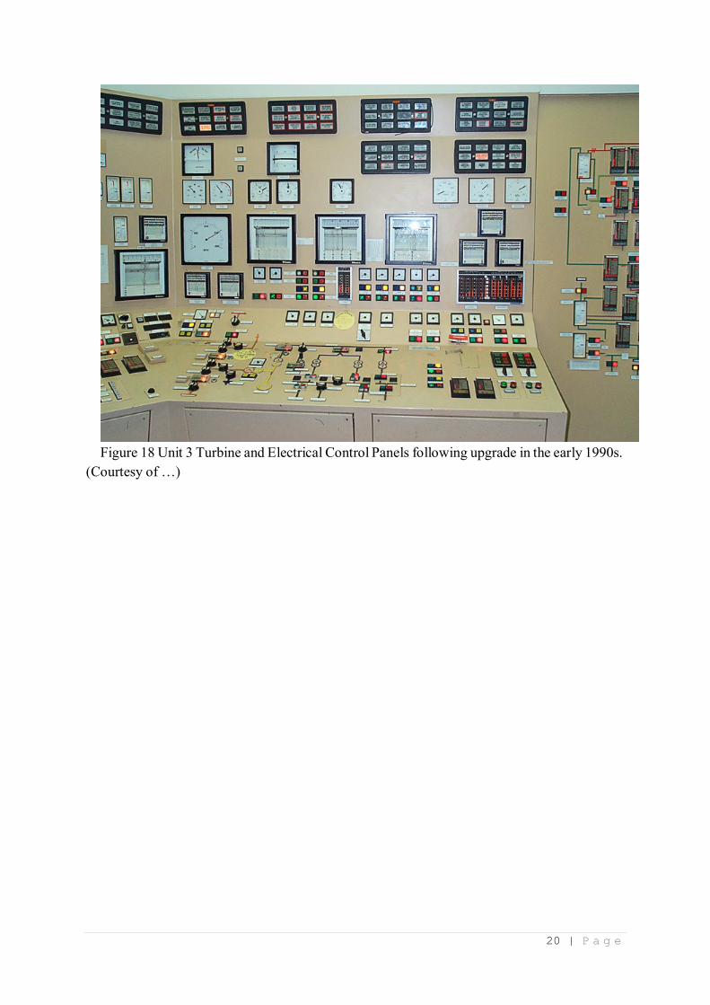
Figure 18 Unit 3 Turbine and Electrical Control Panels following upgrade in the early 1990s.
(Courtesy of …)
21 | P a g e
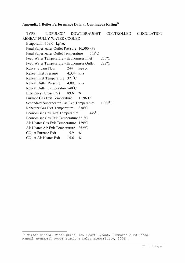
Appendix 1 Boiler Performance Data at Continuous Rating20
TYPE: "LOPULCO" DOWNDRAUGHT CONTROLLED CIRCULATION
REHEAT FULLY WATER COOLED
Evaporation 309.0 kg/sec
Final Superheater Outlet Pressure 16,500 kPa
Final Superheater Outlet Temperature 5650C
Feed Water Temperature - Economiser Inlet 2550C
Feed Water Temperature - Economiser Outlet 2880C
Reheat Steam Flow 244 kg/sec
Reheat Inlet Pressure 4,334 kPa
Reheat Inlet Temperature 3710C
Reheat Outlet Pressure 4,093 kPa
Reheat Outlet Temperature 5400C
Efficiency (Gross CV) 89.6 %
Furnace Gas Exit Temperature 1,1960C
Secondary Superheater Gas Exit Temperature 1,0380C
Reheater Gas Exit Temperature 8380C
Economiser Gas Inlet Temperature 4490C
Economiser Gas Exit Temperature 3210C
Air Heater Gas Exit Temperature 1290C
Air Heater Air Exit Temperature 2520C
CO2 at Furnace Exit 15.9 %
CO2 at Air Heater Exit 14.6 %
20 Boiler General Description, ed. Geoff Byrant, Munmorah APPO School
Manual (Munmorah Power Station: Delta Electricity, 2004).
22 | P a g e
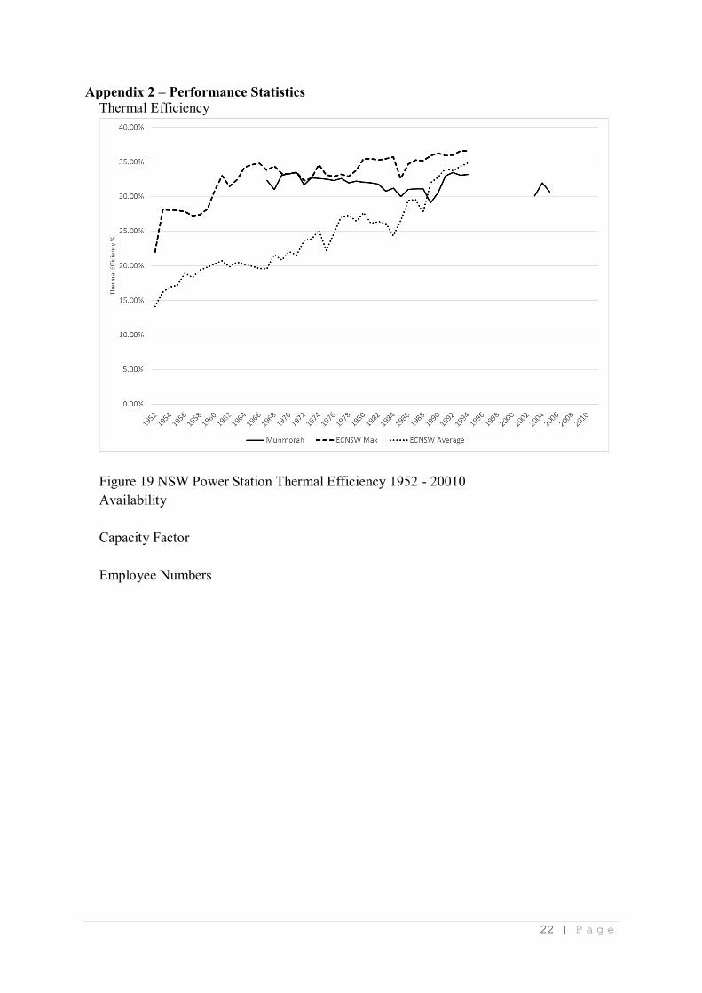
Appendix 2 – Performance Statistics
Thermal Efficiency
Figure 19 NSW Power Station Thermal Efficiency 1952 - 20010
Availability
Capacity Factor
Employee Numbers

23 | P a g e
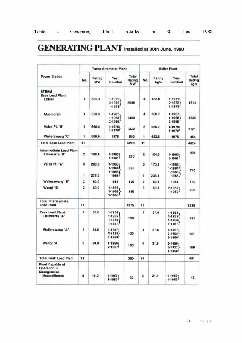
Appendix 3 Generating Plant installed in power stations operated by the Electricity
Commission of New South Wales: May 1950, 30 June 1980 and 30 June 1994.
Table 1 Generating plant installed in power stations on the NSW interconnected System at
May 1950.
24 | P a g e
Table 2 Generating Plant installed at 30 June 1980

25 | P a g e
26 | P a g e
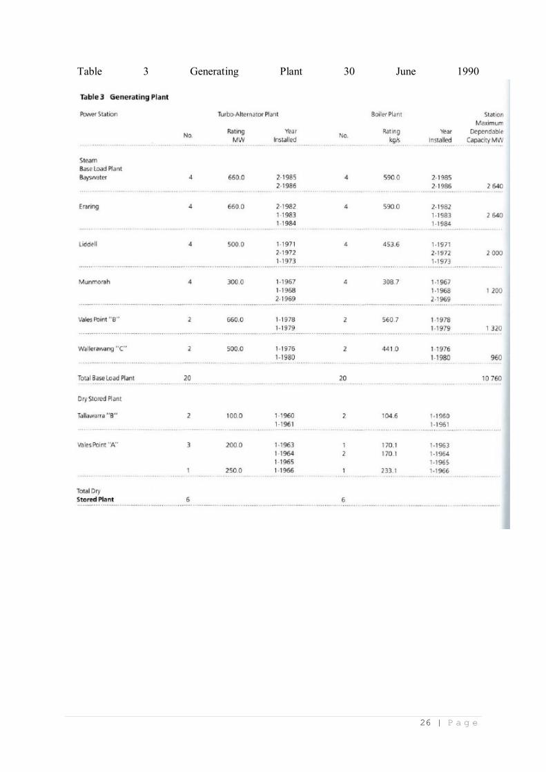
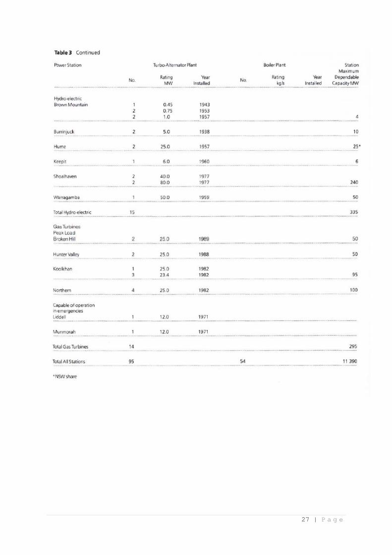
Table 3 Generating Plant 30 June 1990
27 | P a g e
28 | P a g e
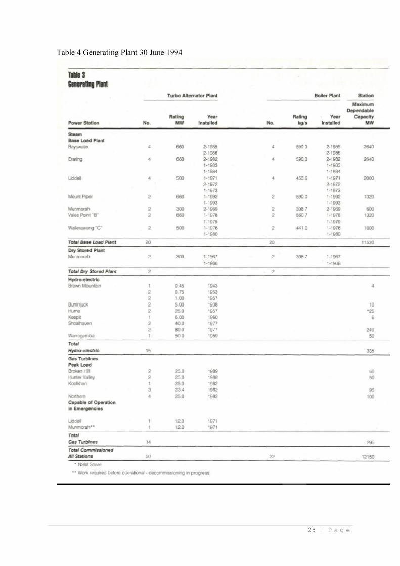
Table 4 Generating Plant 30 June 1994

29 | P a g e
Appendix 4 Burra Charter and the Heritage Assessment of NSW Power Stations
Of the Burra Charter’s three broad procedural guidelines, understanding significance;
develop a policy; and manage the conservation of an item, the ECNSW implemented the first
for a number of its power stations – Ultimo, White Bay, Balmain, Pyrmont, Bunnerong Switch
House, Vales Point ‘A’, Wangi, Penrith, Lithgow and Wallerawang ‘A’ and ‘B’.21 The
recommendations of the subsequent heritage reports were varied, and ranged from the retention
of heritage buildings and a representative ‘slice’ of generation equipment (White Bay);
adaptive reuse as a means of conserving the buildings and grounds (Wangi, Ultimo, Pyrmont
‘A’ Admin Building, Bunnerong Switch House and Penrith), to not recommended for
conservation (Pyrmont ‘B’, Balmain, and Vales Point ‘A’). Similar studies have not been
undertaken for Munmorah or Liddell. Given Vales Point ‘A’ was not recommended for
retention, it is likely that a heritage study of Munmorah or Liddell, if carried out, would come
to a similar recommendation.
21 Ken Thornton and Mark Fetscher, "Liddell Power Station: has a good heart – but needs support and prudent asset management at its end of life" (paper presented at the 18th Australian Engineering
Heritage Conference 2015 Newcastle, 7– 9 December 2015 ).
30 | P a g e
Bibliography
Ayers, C, Campbell, C.L.,. "Automation in the Power Station." The Australasian Engineer
September 1965 (1965).
Boiler General Description. Munmorah Appo School Manual. edited by Geoff Byrant
Munmorah Power Station: Delta Electricity, 2004.
Burns and Roes Worley Pty Ltd. "Feasibility Study for Capacity Upgrad of Munmorah 3 & 4
Units." Sydney, 2005.
"Camp Breakaway - Overview." Camp Breakaway Inc.,
http://www.breakaway.org.au/about/overview
Deans, Alan. "Frank Brady." Australian Business, 1 April 1982.
Doring, C. and M.J. Wangi Power Station Heritage Study. C. & M.J. Doring Pty., 1990.
Electricity Commission of New South Wales / Pacific Power Annual Reports 1953 - 2000,
Sydney: Electricity Commission of New South Wales / Pacific Power, 1953 - 2001.
Feron, Paul H.M. Assessing Post-Combustion Capture for Coal-fired Power Stations in Asia-
Pacifi C Partnership Countries: Final Report to the Department of Resources, Energy
and Tourism. Newcastle: CSIRO Advanced Coal Technology, 2012.
Interviewee P. Personal Communication With Author, 22 September 2016, 2 January 2017.
Interviewee S. Personal Communication With Author, 27 January 2017.
"Munmorah Power Station - Pamphlet." Pacific Power, 1992-1996.
"Munmorah Power Station - Souvenir Opening Book." Sydney: Electricity Commission of
New South Wales, 1969.
Thornton, Ken, and Mark Fetscher. "Liddell Power Station: Has a Good Heart – but Needs
Support and Prudent Asset Management at Its End of Life." Paper presented at the
18th Australian Engineering Heritage Conference 2015 Newcastle, 7– 9 December
2015
Turbine Generator General Description. Munmorah Appo School Manual. edited by Geoff
Byrant Munmorah Power Station: Delta Electricity, 2004.
Vierboom, P., Foreman, C.,. "Boiler Ignition Using Pulverised Coal." Paper presented at the
1996 National Conference on Bulk Materials Handling, Melbourne, 30 September
1996.
Vierboom, P., Hauck, C., Xie, Q.,. "Plasma Ignition Technology for Pulverized Coal Boilers :
A Competitive Edge in Pulverized Coal Power Generation." http://www.energy-
tech.com/steam/article_777d4725-1b0b-530c-a994-4d9251a7647e.html
Walker, K.F. "Analog Controls and Digital Data Processing Applied to Munmorah Power
Station." The Australasian Engineer, no. September 1965 (1965).