multiwalled nanotube faceting unravelledodedhod/papers/paper53.pdf · 2016-12-20 · multiwalled...
TRANSCRIPT

Multiwalled nanotube faceting unravelledItai Leven1†, Roberto Guerra2,3†, Andrea Vanossi2,3, Erio Tosatti2,3,4 and Oded Hod1*
Nanotubes show great promise for miniaturizing advanced technologies. Their exceptional physical properties areintimately related to their morphological and crystal structure. Circumferential faceting of multiwalled nanotubesreinforces their mechanical strength and alters their tribological and electronic properties. Here, the nature of thisimportant phenomenon is fully rationalized in terms of interlayer registry patterns. Regardless of the nanotube identity(that is, diameter, chirality, chemical composition), faceting requires the matching of the chiral angles of adjacent layers.Above a critical diameter that corresponds well with experimental results, achiral multiwalled nanotubes display evenlyspaced extended axial facets whose number equals the interlayer difference in circumferential unit cells. Elongated helicalfacets, commonly observed in experiment, appear in nanotubes that exhibit small interlayer chiral angle mismatch. Whenthe wall chiralities are uncorrelated, faceting is suppressed and outer layer corrugation, which is induced by the Moirésuperlattice, is obtained in agreement with experiments. Finally, we offer an explanation for the higher incidence offaceting in multiwalled boron nitride nanotubes with respect to their carbon-based counterparts.
As their name suggests, nanotubes are traditionally thought ofas cylindrical structures that possess a circular cross-section.Nevertheless, under certain conditions multiwalled nano-
tubes (MWNTs) exhibit circumferential faceting, which results inpolygonal cross-sections1–8. This, in turn, leads to considerablereinforcement of their mechanical properties7,9 thus paving theway for fulfilling their potential as next-generation ultrahigh-strength materials10–12. Furthermore, it may have considerableimpact on their tribological, electronic and optical properties. Athorough understanding of the nature and origin of thisphenomenon is thus crucial for the rational design of robust anddurable nanotube-based electromechanical devices that can with-stand repeated mechanical loads.
The underlying mechanism for nanotube faceting clearlyinvolves a balance between the interlayer attractive interactionsthat are gained at the faceted regions and the mechanical strainaccumulated at the vertices. This understanding has been the basisfor several theoretical studies that adopted the continuum modelapproach13–16. Such models provide valuable insights regardingthe general phenomenon; however, they are limited in their abilityto depict important system-specific characteristics that require adetailed atomistic description. This was clearly demonstratedwhen a fully atomistic dispersion-corrected anisotropic tight-binding Hamiltonian model for graphitic systems was used to inves-tigate pentagonal faceting in nested multiwalled zigzag nanotubes17.Nevertheless, many important questions remain, including: what arethe detailed conditions required for faceting to occur? What dictatesthe number of facets formed? And why is this phenomenon morecommonly observed in multiwalled boron nitride nanotubes(MWBNNTs) than in their carbon-based counterparts?
In the present study we identify the atomistic origin of nanotubefaceting as resulting from extended interlayer registry patternsthat appear between the curved hexagonal lattices that form thenanotube walls. We find that when two adjacent walls have match-ing chiral angles, their curvature difference forms localized out-of-registry regions that are evenly spaced along the circumference ofthe tube and are separated by extended in-registry arcs. Upon
structural relaxation the former become vertices whereas the latterform commensurate facets. Interestingly, the number of facets isdictated by the difference in the circumferential unit cells betweentwo adjacent layers. Furthermore, the facets can be either axial orhelical depending on the chiral angle difference of adjacent layers.Finally, the critical tube diameter above which faceting is foundlies between 5 and 13 nm depending on the tube chirality, ingood agreement with experimental observations7. On the basis ofthese findings we offer an explanation for the relative abundanceof faceting in inorganic nanotubes with respect to theirgraphitic counterparts.
Achiral double-walled nanotubesLet us first discuss achiral double-walled nanotubes (DWNTs). Fourdifferent types of DWNT system exist, where the inner and outerlayers can be either zigzag (ZZ) or armchair (AC). In Fig. 1 wepresent relaxed structures of ZZ@ZZ, AC@AC and ZZ@ACdouble-walled carbon nanotubes (DWCNTs) and double-walledboron nitride nanotubes (DWBNNTs) with outer diameters inthe range of 5–20 nm. Here the notation ZZ@AC, for example, rep-resents a DWNT with an inner ZZ tube inside an outer AC shell.The most prominent feature evident in Fig. 1 is that for achiralDWNTs cross-sectional polygonalization occurs when the innerand outer shells share the same chiral angle, whereas for themixed ZZ@AC systems the cross-section remains circular.Furthermore, both the carbon and BN systems studied exhibit acritical diameters of 5–7 nm and 9–13 nm for the AC@AC andZZ@ZZ DWNTs, respectively, beyond which faceting appears.This is in remarkable agreement with recent experimental obser-vations that suggest a critical faceting diameter of approximately12 nm in MWBNNTs7.
To elucidate the interlayer effects underlying the formation offacets, in Fig. 1 we visualize the degree of local interlayer commen-surability by colouring each atom of the outer shell according to thevalue of its local registry index (LRI, see Methods and SupplementarySection 4 for a detailed explanation). Focusing first on the pre-optimized structures with circular cross-sections (see rows marked
1Department of Physical Chemistry, School of Chemistry, The Raymond and Beverly Sackler Faculty of Exact Sciences and The Raymond and Beverly SacklerCenter for Computational Molecular and Materials Science, Tel Aviv University, Tel Aviv 6997801, Israel. 2International School for Advanced Studies (SISSA),Via Bonomea 265, 34136 Trieste, Italy. 3CNR-IOM Democritos National Simulation Center, Via Bonomea 265, 34136 Trieste, Italy. 4The Abdus Salam InternationalCentre for Theoretical Physics (ICTP), Strada Costiera 11, 34151 Trieste, Italy. †These authors contributed equally to this work. *e-mail: [email protected]
ARTICLESPUBLISHED ONLINE: 22 AUGUST 2016 | DOI: 10.1038/NNANO.2016.151
NATURE NANOTECHNOLOGY | VOL 11 | DECEMBER 2016 | www.nature.com/naturenanotechnology1082
© 2016 Macmillan Publishers Limited, part of Springer Nature. All rights reserved.
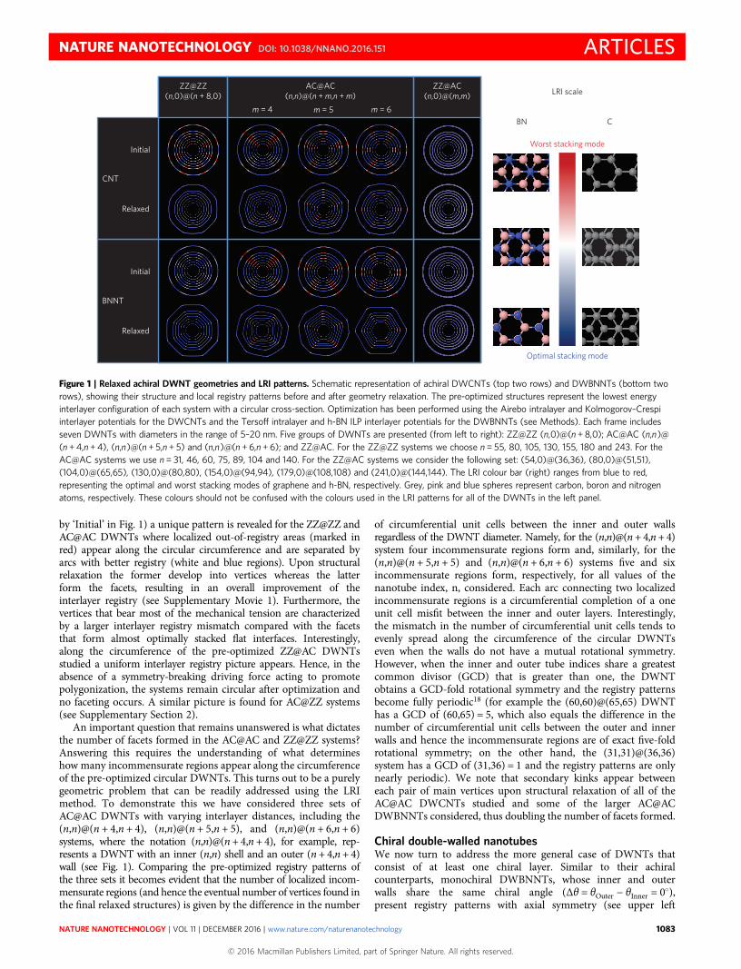
by ‘Initial’ in Fig. 1) a unique pattern is revealed for the ZZ@ZZ andAC@AC DWNTs where localized out-of-registry areas (marked inred) appear along the circular circumference and are separated byarcs with better registry (white and blue regions). Upon structuralrelaxation the former develop into vertices whereas the latterform the facets, resulting in an overall improvement of theinterlayer registry (see Supplementary Movie 1). Furthermore, thevertices that bear most of the mechanical tension are characterizedby a larger interlayer registry mismatch compared with the facetsthat form almost optimally stacked flat interfaces. Interestingly,along the circumference of the pre-optimized ZZ@AC DWNTsstudied a uniform interlayer registry picture appears. Hence, in theabsence of a symmetry-breaking driving force acting to promotepolygonization, the systems remain circular after optimization andno faceting occurs. A similar picture is found for AC@ZZ systems(see Supplementary Section 2).
An important question that remains unanswered is what dictatesthe number of facets formed in the AC@AC and ZZ@ZZ systems?Answering this requires the understanding of what determineshow many incommensurate regions appear along the circumferenceof the pre-optimized circular DWNTs. This turns out to be a purelygeometric problem that can be readily addressed using the LRImethod. To demonstrate this we have considered three sets ofAC@AC DWNTs with varying interlayer distances, including the(n,n)@(n + 4,n + 4), (n,n)@(n + 5,n + 5), and (n,n)@(n + 6,n + 6)systems, where the notation (n,n)@(n + 4,n + 4), for example, rep-resents a DWNT with an inner (n,n) shell and an outer (n + 4,n + 4)wall (see Fig. 1). Comparing the pre-optimized registry patterns ofthe three sets it becomes evident that the number of localized incom-mensurate regions (and hence the eventual number of vertices found inthe final relaxed structures) is given by the difference in the number
of circumferential unit cells between the inner and outer wallsregardless of the DWNT diameter. Namely, for the (n,n)@(n+ 4,n+ 4)system four incommensurate regions form and, similarly, for the(n,n)@(n + 5,n + 5) and (n,n)@(n + 6,n + 6) systems five and sixincommensurate regions form, respectively, for all values of thenanotube index, n, considered. Each arc connecting two localizedincommensurate regions is a circumferential completion of a oneunit cell misfit between the inner and outer layers. Interestingly,the mismatch in the number of circumferential unit cells tends toevenly spread along the circumference of the circular DWNTseven when the walls do not have a mutual rotational symmetry.However, when the inner and outer tube indices share a greatestcommon divisor (GCD) that is greater than one, the DWNTobtains a GCD-fold rotational symmetry and the registry patternsbecome fully periodic18 (for example the (60,60)@(65,65) DWNThas a GCD of (60,65) = 5, which also equals the difference in thenumber of circumferential unit cells between the outer and innerwalls and hence the incommensurate regions are of exact five-foldrotational symmetry; on the other hand, the (31,31)@(36,36)system has a GCD of (31,36) = 1 and the registry patterns are onlynearly periodic). We note that secondary kinks appear betweeneach pair of main vertices upon structural relaxation of all of theAC@AC DWCNTs studied and some of the larger AC@ACDWBNNTs considered, thus doubling the number of facets formed.
Chiral double-walled nanotubesWe now turn to address the more general case of DWNTs thatconsist of at least one chiral layer. Similar to their achiralcounterparts, monochiral DWBNNTs, whose inner and outerwalls share the same chiral angle (Δθ = θOuter − θInner = 0○),present registry patterns with axial symmetry (see upper left
CNT
BNNT
ZZ@ZZ(n,0)@(n + 8,0)
Initial
Relaxed
AC@AC(n,n)@(n + m,n + m)
ZZ@AC(n,0)@(m,m)
m = 4 m = 5 m = 6
Initial
Relaxed
BN C
LRI scale
Optimal stacking mode
Worst stacking mode
Figure 1 | Relaxed achiral DWNT geometries and LRI patterns. Schematic representation of achiral DWCNTs (top two rows) and DWBNNTs (bottom tworows), showing their structure and local registry patterns before and after geometry relaxation. The pre-optimized structures represent the lowest energyinterlayer configuration of each system with a circular cross-section. Optimization has been performed using the Airebo intralayer and Kolmogorov–Crespiinterlayer potentials for the DWCNTs and the Tersoff intralayer and h-BN ILP interlayer potentials for the DWBNNTs (see Methods). Each frame includesseven DWNTs with diameters in the range of 5–20 nm. Five groups of DWNTs are presented (from left to right): ZZ@ZZ (n,0)@(n + 8,0); AC@AC (n,n)@(n + 4,n + 4), (n,n)@(n + 5,n + 5) and (n,n)@(n + 6,n + 6); and ZZ@AC. For the ZZ@ZZ systems we choose n = 55, 80, 105, 130, 155, 180 and 243. For theAC@AC systems we use n = 31, 46, 60, 75, 89, 104 and 140. For the ZZ@AC systems we consider the following set: (54,0)@(36,36), (80,0)@(51,51),(104,0)@(65,65), (130,0)@(80,80), (154,0)@(94,94), (179,0)@(108,108) and (241,0)@(144,144). The LRI colour bar (right) ranges from blue to red,representing the optimal and worst stacking modes of graphene and h-BN, respectively. Grey, pink and blue spheres represent carbon, boron and nitrogenatoms, respectively. These colours should not be confused with the colours used in the LRI patterns for all of the DWNTs in the left panel.
NATURE NANOTECHNOLOGY DOI: 10.1038/NNANO.2016.151 ARTICLES
NATURE NANOTECHNOLOGY | VOL 11 | DECEMBER 2016 | www.nature.com/naturenanotechnology 1083
© 2016 Macmillan Publishers Limited, part of Springer Nature. All rights reserved.

panel of Fig. 2; results for DWCNTs show a very similar behav-iour and are presented in Supplementary Section 3). As before,localized incommensurate regions appear along thecircumference of the pre-optimized structures. Nevertheless, the(near-) rotational symmetry obtained for the achiral systems islost and their degree of registry mismatch varies. Here tooupon structural relaxation the incommensurate regions thindown and form corners that are separated by axial facets withincreased interlayer commensurability (middle left panel). Thisis more clearly seen in the interlayer distance analysis (lower leftpanel), where the facets present a nearly optimal (approximately3.33 Å) interlayer separation, whereas the vertices show anincrease of up to 0.2 Å.
The four right columns of Fig. 2 show various bichiralDWBNNTs, whose inner and outer walls differ in their chiralangles (Δθ ≠ 0○). These systems present non-axial registry patternsthat coil around the circumference of the tube with a helicalangle that depends on the chiral angle difference between thetwo walls. For the bichiral DWBNNTs with smaller chiral anglemismatches Δθ = 0.253○ and 0.657○( ), long incommensuratestripes appear that are separated by helical almost commensuratearcs (upper panels of the second and third columns). Similar tothe monochiral DWBNNT case, upon structural relaxation theincommensurate stripes become thinner and form corners withincreased interlayer distances whereas the nearly commensuratearcs turn into helical facets with close-to-optimal interlayerspacing (see the middle and lower panels). This is in fact themost common faceting pattern observed in experiments2,3,5,6. Forlarger chiral angle mismatches (the two rightmost columns) theincommensurate regions become discontinuous (upper panels)resulting in non-faceted optimized structures (middle andlower panels).
Two-dimensional mappingThis complex behaviour can be fully rationalized by the theory ofMoiré patterns in planar mismatched hexagonal lattices19. To thisend, the registry patterns that appear in a DWNT with a circularcross-section are mapped onto the corresponding flat bilayersystem. This is achieved by first unrolling the tube shells to obtaintwo infinite parallel ribbons followed by a contraction of the widerribbon, representing the outer shell, to match the width of theinner ribbon, thus mimicking curvature effects (see Fig. 3a)18,19.The resulting planar bilayer is thus periodic along the circumferential
direction. The obtained Moiré patterns form a super structurewhose lattice vectors are given by:
LM1 =
��3
√d sin(�θ)
2(1 + c′h /ch) sinΔθ
2
( )
× 2 ˆ̃x + (1 − c′h /ch) cotΔθ
2
( )− (1 + c′h /ch) cot(�θ)
[ ]ˆ̃y
{ }
LM2 =
��3
√d sin �θ −
π
3
( )
2(1 + c′h /ch) sinΔθ
2
( )
× 2 ˆ̃x + (1 − c′h /ch) cotΔθ
2
( )− (1 + c′h /ch) cot �θ −
π
3
( )[ ]ˆ̃y
{ }
⎧⎪⎪⎪⎪⎪⎪⎪⎪⎪⎪⎪⎪⎪⎪⎪⎪⎪⎪⎨⎪⎪⎪⎪⎪⎪⎪⎪⎪⎪⎪⎪⎪⎪⎪⎪⎪⎪⎩
(1)
where ch and c′h are the chiral vector lengths of the inner and outerNT walls, respectively, �θ is the average chiral angle of the two tubewalls, Δθ is the corresponding chiral angle difference, d is thenearest-neighbour interatomic distance within each tube wall andˆ̃x, ˆ̃y
{ }is the orthogonal reference frame defined by two unit
vectors lying along the chiral and translation vector directionsof the inner tube wall (a detailed derivation is given inSupplementary Section 7).
For both achiral and monochiral nanotubes Δθ = 0° and theMoiré lattice vectors become parallel to the translational vector ofthe tube with diverging length, thus resulting in the extendedaxial LRI patterns appearing both in the curved (Fig. 1 and leftcolumn of Fig. 2) and in the planar (Fig. 3c,d) representation ofthe DWNTs. Upon increasing Δθ the Moiré lattice vectors deviatefrom the translational vector, thus developing the commonlyobserved helical patterns along the circumference of the tube(Figs 2 and 3e). Importantly, as the length of the Moiré latticevectors reduces with increasing Δθ (see Fig. 3b) the density oflattice mismatch regions increases (see the right column of Figs 2and 3f) thus suppressing the formation of extended facets. Thisclearly demonstrates that faceting requires matching of the inter-layer chiral angle20. We note, however, that even in the case ofΔθ = 1.741°, with LM1
∣∣ ∣∣ = 4.305 nm and LM2∣∣ ∣∣ = 17.157 nm, the
optimized structure exhibits interlayer distance variations thatcorrelate with the registry patterns. Notably, similar variationshave been recently observed on the surface of CNTs21,22.
Initial LRI
Relaxed LRI
Relaxed interlayerspacing
Δθ = 0° Δθ = 0.253° Δθ = 0.657° Δθ = 1.141° Δθ = 1.741°
Interlayer spacing (Å)
3.55
3.25
3.325
3.4
3.475
Figure 2 | Relaxed chiral DWBNNT geometries, LRI patterns and interlayer distance. Schematic representation of (120,100)@(126,105) (leftmost column),(60,60)@(66,65) (second column), (70,70)@(77,74) (third column), (68,68)@(75,70) (fourth column) and (71,71)@(80,72) (rightmost column)DWBNNTs showing their local registry patterns before (top row) and after (middle row) geometry relaxation performed using the Tersoff intralayerand h-BN ILP interlayer potentials (see Methods). The colour bar on the right refers to the interlayer spacing of the different systems presented in thebottom row. The colours used in the LRI patterns are the same as in Fig. 1. The chiral angle difference between the inner and outer shells is indicatedabove each column.
ARTICLES NATURE NANOTECHNOLOGY DOI: 10.1038/NNANO.2016.151
NATURE NANOTECHNOLOGY | VOL 11 | DECEMBER 2016 | www.nature.com/naturenanotechnology1084
© 2016 Macmillan Publishers Limited, part of Springer Nature. All rights reserved.

ConclusionsTo summarize, the origin of MWNT circumferential faceting isfound to be a direct consequence of the interlayer lattice registry pat-terns. The appearance of extended facets requires chiral anglematching between adjacent nanotube layers. For two achiral neigh-bouring layers of the same type (AC or ZZ) extended axial facetswith (almost) perfect rotational symmetry are formed, the numberof which is dictated by the corresponding difference in thenumber of circumferential unit cells. The critical diameter for facet-ing in these systems is found to be 5–13 nm, in good agreement withexperimental findings. Similarly, monochiral layers presentextended axial facets but with reduced rotational symmetry.Bichiral adjacent layers exhibit helical facets whose length decreasesand helix angle increases as the interlayer chiral angle differenceincreases up to a point at which facet formation is suppressed,resulting in a corrugated nanotube surface in good agreementwith experimental findings. This in turn provides an explanationfor why faceting is more abundant in MWBNNTs than inMWCNTs. The polar nature of the heteronuclear BN covalentbonds in MWBNNTs introduces interlayer electrostatic inter-actions23 that are sufficient to induce the interwall chiral angle
correlation5,24–26 that is required for the formation of facets. Thelack of such interactions in MWCNTs, which are composed ofnonpolarhomonuclearC–Ccovalentbonds, often results inpracticallyrandom chiral angle distributions in the different nanotubelayers21,22,27–34, which may explain why mostly non-faceted structuresappear. We note however that low-temperature synthesis conditionshave been reported to produce monochiral MWCNTs27,35. It is there-fore evident that gaining control over interlayer registry matchingprovides a route for the mechanical enforcement7 as well as the tuningof tribological9, electronic8, and thermal properties of MWNTs36.
MethodsMethods and any associated references are available in the onlineversion of the paper.
Received 13 January 2016; accepted 15 July 2016;published online 22 August 2016
References1. Liu, M. & Cowley, J. M. Structures of the helical carbon nanotubes. Carbon 32,
393–403 (1994).
(75,75)@(80,80)d
(120,100)@(126,105)
(70,70)@(77,74) (71,71)@(80,72)
b
Unrolling
Contraction
a
L2M
L1M
Tube
axi
s
Circumference
c
fe
Δθ = 0.657°
Δθ = 0° Δθ = 0°
Δθ = 1.741°
0.5 1.0 1.5Δθ (°)
0
200
400
600
Moi
ré s
uper
latt
ice
vect
orle
ngth
(nm
)
L1M
L2M
Figure 3 | Planar mapping of DWNT registry patterns. a, Schematic illustration of NT unrolling and compression, resulting in the planar mapping of theDWNT registry patterns. The atoms of the inner and outer walls are coloured green and blue, respectively. b, Dependence of the Moiré lattice vector lengthson the chiral angle difference between the DWNT walls as calculated using equation (1). c,d, Planar mapping of the registry patterns of the (75,75)@(80,80)and (120,100)@(126,105) DWBNNTs with Δθ = 0° characterized by axial registry patterns. e,f, Planar mapping of the helical registry patterns of the(70,70)@(77,74) and (71,71)@(80,72) DWBNNTs with Δθ = 0.657° and Δθ = 1.741°, respectively. The Moiré superlattice cell of the (71,71)@(80,72)DWBNNT calculated using equation (1) is represented by the white parallelogram in f. The horizontal and vertical axes in c–f correspond to thecircumferential and axial directions of the DWBNNTs, respectively. The LRI colour bar is the same as in Fig. 1.
NATURE NANOTECHNOLOGY DOI: 10.1038/NNANO.2016.151 ARTICLES
NATURE NANOTECHNOLOGY | VOL 11 | DECEMBER 2016 | www.nature.com/naturenanotechnology 1085
© 2016 Macmillan Publishers Limited, part of Springer Nature. All rights reserved.

2. Gogotsi, Y., Libera, J. A., Kalashnikov, N. & Yoshimura, M. Graphite polyhedralcrystals. Science 290, 317–320 (2000).
3. Zhang, G., Jiang, X. & Wang, E. Tubular graphite cones. Science 300,472–474 (2003).
4. Zhang, G. Y., Bai, X. D., Wang, E. G., Guo, Y. & Guo, W. Monochiral tubulargraphite cones formed by radial layer-by-layer growth. Phys. Rev. B 71,113411 (2005).
5. Celik-Aktas, A., Zuo, J. M., Stubbins, J. F., Tang, C. C. & Bando, Y. Double-helixstructure in multiwall boron nitride nanotubes. Acta Crystallogr. Sect. A 61,533–541 (2005).
6. Golberg, D., Mitome, M., Bando, Y., Tang, C. C. & Zhi, C. Y. Multi-walled boronnitride nanotubes composed of diverse cross-section and helix type shells.Appl. Phys. A 88, 347–352 (2007).
7. Garel, J. et al. Ultrahigh torsional stiffness and strength of boron nitridenanotubes. Nano Lett. 12, 6347–6352 (2012).
8. Garel, J. et al. BCN nanotubes as highly sensitive torsional electromechanicaltransducers. Nano Lett. 14, 6132–6137 (2014).
9. Nigues, A., Siria, A., Vincent, P., Poncharal, P. & Bocquet, L. Ultrahigh interlayerfriction in multiwalled boron nitride nanotubes. Nat. Mater. 13, 688–693 (2014).
10. Golberg, D. et al. Boron nitride nanotubes and nanosheets. ACS Nano 4,2979–2993 (2010).
11. De Volder, M. F. L., Tawfick, S. H., Baughman, R. H. & Hart, A. J. Carbonnanotubes: present and future commercial applications. Science 339,535–539 (2013).
12. Arash, B., Wang, Q. & Varadan, V. K. Mechanical properties of carbonnanotube/polymer composites. Sci. Rep. 4, 6479 (2014).
13. Yoon, M., Howe, J., Tibbetts, G., Eres, G. & Zhang, Z. Polygonization andanomalous graphene interlayer spacing of multi-walled carbon nanofibers.Phys. Rev. B 75, 165402 (2007).
14. Golovaty, D. & Talbott, S. Continuum model of polygonization of carbonnanotubes. Phys. Rev. B 77, 081406(R) (2008).
15. Tibbetts, K., Doe, R. & Ceder, G. Polygonal model for layered inorganicnanotubes. Phys. Rev. B 80, 014102 (2009).
16. Mu, W., Zhang, G. & Ou-Yang, Z. Spontaneous polygonization of multiwalledcarbon nanotubes: perturbation analysis. Jpn. J. Appl. Phys. 51, 065101 (2012).
17. Palser, A. H. R. Interlayer interactions in graphite and carbon nanotubes.Phys. Chem. Chem. Phys. 1, 4459–4464 (1999).
18. Hod, O. Quantifying the stacking registry matching in layered materials.Isr. J. Chem. 50, 506–514 (2010).
19. Koshino, M., Moon, P. & Son, Y.-W. Incommensurate double-walled carbonnanotubes as one-dimensional moiré crystals. Phys. Rev. B 91, 035405 (2015).
20. Kolmogorov, A. N. & Crespi, V. H. Smoothest bearings: interlayer sliding inmultiwalled carbon nanotubes. Phys. Rev. Lett. 85, 4727–4730 (2000).
21. Hashimoto, A. et al. Atomic correlation between adjacent graphene layers indouble-wall carbon nanotubes. Phys. Rev. Lett. 94, 045504 (2005).
22. Schouteden, K., Volodin, A., Li, Z. & Van Haesendonck, C. Atomically resolvedMoiré-type superstructures in double-walled carbon nanotubes. Carbon 61,379–385 (2013).
23. Hod, O. Graphite and hexagonal boron-nitride have the same interlayerdistance. Why? J. Chem. Theory and Comput. 8, 1360–1369 (2012).
24. Golberg, D. et al. Fine structure of boron nitride nanotubes producedfrom carbon nanotubes by a substitution reaction. J. Appl. Phys. 86,2364–2366 (1999).
25. Golberg, D., Bando, Y., Kurashima, K. & Sato, T. Ropes of BN multi-wallednanotubes. Solid State Commun. 116, 1–6 (2000).
26. Celik-Aktas, A., Zuo, J. M., Stubbins, J. F., Tang, C. & Bando, Y. Structure andchirality distribution of multiwalled boron nitride nanotubes. Appl. Phys. Lett.86, 133110 (2005).
27. Xu, Z., Bai, X., Wang, Z. L. & Wang, E. Multiwall carbon nanotubes made ofmonochirality graphite shells. J. Am. Chem. Soc. 128, 1052–1053 (2006).
28. Zuo, J. M., Vartanyants, I., Gao, M., Zhang, R. & Nagahara, L. A. Atomicresolution imaging of a carbon nanotube from diffraction intensities. Science300, 1419–1421 (2003).
29. Li, F. et al. Identification of the constituents of double-walled carbon nanotubesusing Raman spectra taken with different laser-excitation energies. J. Mater. Res.18, 1251–1258 (2003).
30. Koziol, K., Shaffer, M. & Windle, A. Three-dimensional internal order inmultiwalled carbon nanotubes grown by chemical vapor deposition. Adv. Mater.17, 760–763 (2005).
31. Ducati, C. et al. Crystallographic order in multi-walled carbon nanotubessynthesized in the presence of nitrogen. Small 2, 774–784 (2006).
32. Hirahara, K. et al. Chirality correlation in double-wall carbon nanotubes asstudied by electron diffraction. Phys. Rev. B 73, 195420 (2006).
33. Gao, M., Zuo, J. M., Zhang, R. & Nagahara, L. A. Structure determinations ofdouble-wall carbon nanotubes grown by catalytic chemical vapor deposition.J. Mater. Sci. 41, 4382–4388 (2006).
34. Guan, L., Suenaga, K. & Iijima, S. Smallest carbon nanotube assigned withatomic resolution accuracy. Nano Lett. 8, 459–462 (2008).
35. Guo, W. & Guo, Y. Energy optimum chiralities of multiwalled carbon nanotubes.J. Am. Chem. Soc. 129, 2730–2731 (2007).
36. Liu, K. H. et al. Van der Waals-coupled electronic states in incommensuratedouble-walled carbon nanotubes. Nat. Phys. 10, 737–742 (2014).
AcknowledgementsO.H. acknowledges the Lise-Meitner Minerva Center for Computational QuantumChemistry and the Center for Nanoscience and Nanotechnology at Tel-Aviv University fortheir generous financial support. Work in Trieste was carried out under ERC Grant 320796MODPHYSFRICT. EU COST Action MP1303 is also gratefully acknowledged.
Author contributionsI.L. and R.G. coded the relevant force-fields, performed the geometry optimizationsand actively participated in the analysis of the results and the writing of the manuscript.I.L. and O.H. coded the unrolled nanotube registry pattern analysis tool and analysed thecorresponding results. E.T., A.V. and O.H. guided the research and data analysis andled the writing of the manuscript.
Additional informationSupplementary information is available in the online version of the paper. Reprints andpermissions information is available online at www.nature.com/reprints. Correspondence andrequests for materials should be addressed to O.H.
Competing financial interestsThe authors declare no competing financial interests.
ARTICLES NATURE NANOTECHNOLOGY DOI: 10.1038/NNANO.2016.151
NATURE NANOTECHNOLOGY | VOL 11 | DECEMBER 2016 | www.nature.com/naturenanotechnology1086
© 2016 Macmillan Publishers Limited, part of Springer Nature. All rights reserved.

MethodsGeometry optimization of all DWNTs considered have been performed usingquenched dynamics techniques with dedicated intra- and interlayer classicalforce-fields. For CNTs the intralayer interactions have been described utilizing boththe Tersoff37 potential (see Supplementary Section 1) and the reactive Airebo38
force-field, adopting the parameterization of ref. 39. The interlayer interactions ofthese systems have been described by the registry dependent Kolmogorov–Crespi40
potential. For the intralayer interactions of BNNTS we have used the Tersoff41
force-field as parameterized in ref. 41 for BN-based systems along with our recentlydeveloped h-BN interlayer potential (h-BN ILP) with frozen partial charges(see Supplementary Section 5)42. Cyclic boundary conditions have been applied forall achiral and monochiral (bearing the same chirality) DWNTs. We further verifythe robustness of our results towards potential many-body dispersion effectsthat have been neglected in the parameterization procedure of the h-BN ILP(see Supplementary Section 6).
For the registry analysis we have extended the global registry index (GRI)method, which quantifies the interlayer stacking registry in rigid layeredmaterials18,43–45, by defining the local registry index that characterizes the localdegree of lattice commensurability in various regions along the circumference of thenanotube. In short, in the original GRI approach a single parameter is calculated asthe sums and differences of all of the projected atomic-centred circle overlapsbetween adjacent layers to characterize the overall registry matching of the system ata given interlayer configuration. In the LRI approach each atomic centre is assigned anumber that indicates the local degree of registry in its immediate surroundingenvironment. This is achieved by calculating the projected overlaps between thecircles (or Gaussians) assigned to a given atom and one of its nearest neighbours inone layer and all of the circles (Gaussians) of its adjacent layer using the samesystem-dependent circle radii (Gaussian standard deviation), formula andnormalization as in the GRI approach. This procedure is repeated for all of the
nearest neighbours of the given atom and the average result is assigned to this atomas its LRI, such that a value of 0 marks good local registry (lowest interlayer energy)and 1 represents bad local registry (highest interlayer energy). The LRI map is thenobtained by plotting one of the NT layers and using a colour scheme in which anatom with the highest LRI value of 1 is coloured in red and an atom having thelowest LRI value (0) is coloured in blue (see Figs 1–3). For further details seeSupplementary Section 4.
References37. Tersoff, J. Modeling solid-state chemistry—interatomic potentials for
multicomponent systems. Phys. Rev. B 39, 5566–5568 (1989).38. Stuart, S. J., Tutein, A. B. & Harrison, J. A. A reactive potential for hydrocarbons
with intermolecular interactions. J. Chem. Phys. 112, 6472 (2000).39. Lindsay, L. & Broido, D. A. Optimized Tersoff and Brenner empirical potential
parameters for lattice dynamics and phonon thermal transport in carbonnanotubes and graphene. Phys. Rev. B 81, 205441 (2010).
40. Kolmogorov, A. N. & Crespi, V. H. Registry-dependent interlayer potential forgraphitic systems. Phys. Rev. B 71, 235415 (2005).
41. Sevik, C., Kinaci, A., Haskins, J. B. & Çağın, T. Characterization of thermaltransport in low-dimensional boron nitride nanostructures. Phys. Rev. B 84,085409 (2011).
42. Leven, I., Azuri, I., Kronik, L. & Hod, O. Inter-layer potential for hexagonalboron nitride. J. Chem. Phys. 140, 104106 (2014).
43. Marom, N. et al. Stacking and registry effects in layered materials: the case ofhexagonal boron nitride. Phys. Rev. Lett. 105, 046801 (2010).
44. Hod, O. Interlayer commensurability and superlubricity in rigid layeredmaterials. Phys. Rev. B 86, 075444 (2012).
45. Hod, O. The registry index: a quantitative measure of materials’ interfacialcommensurability. ChemPhysChem 14, 2376–2391 (2013).
NATURE NANOTECHNOLOGY DOI: 10.1038/NNANO.2016.151 ARTICLES
NATURE NANOTECHNOLOGY | www.nature.com/naturenanotechnology
© 2016 Macmillan Publishers Limited, part of Springer Nature. All rights reserved.