multiple-output regulated dc power supply pmp series · 2019. 9. 4. · pmp_if i how to read this...
TRANSCRIPT

Communication Interface Manual
Multiple-output Regulated DC Power Supply
Part No. Z1-003-922, IA004071
Dec. 2006
PMP Series

Use of Operation ManualPlease read through and understand this Operation Manual before operating the product. After reading, always keep the manual nearby so that you may refer to it as needed. When moving the product to another location, be sure to bring the manual as well.If you find any misplaced or missing pages in this manual, they will be replaced. If the manual gets lost or soiled, a new copy can be provided for a fee. In either case, please contact Kikusui distributor/agent, and provide the “Kikusui Part No.” given on the cover.This manual has been prepared with the utmost care; however, if you have any questions, or note any errors or omissions, please contact Kikusui dis-tributor/agent.
Microsoft and Windows are registered trademarks of Microsoft Corporation in the United States and/or other countries.Other company names and product names used in this manual are generally trademarks or registered trademarks of the respective companies.
Reproduction and reprinting of this operation manual, in whole or in part, without written permission is prohibited. Both unit specifications and manual contents are subject to change without notice.
Copyright© 2006 Kikusui Electronics Corporation

PMP_IF i
How to Read This Manual
Preface
This manual is intended for first-time users of the PMP Series (with a GPIB, RS232C, or USB interface option). It gives an overview of the PMP and describes various settings, etc.Read this manual thoroughly to use the functions of the PMP effectively. You can also review this manual when you are confused about an operation or when a problem occurs.
How to read this manual
The Multiple-output Regulated DC Power Supply PMP Series Communication Interface Manual explains the settings and commands for remotely controlling the PMP using the interface and gives sample programs.
Related manuals
For the safety precautions, installation, operation, and specifications of the PMP, read the accompanying Multiple-output Regulated DC Power Supply PMP Series Operation Manual.
Intended readers of this manual
This manual is written for readers with sufficient basic knowledge of how to control instruments using a personal computer.

ii PMP_IF
Structure of this manual
This manual consists of the following chapters. The following outlines each chapter.
Chapter 1 Remote ControlThis chapter gives an overview of the remote control function and explains the SCPI command structure, syntax, and so on used in the remote control.
Chapter 2 CommandsThis chapter describes the details of commands and registers.
AppendixThe appendix contains lists of messages, lists of command errors, tutorials, sample programs, and interface specifications.
Notations used in the manual
• The following marks are used with the corresponding expla-nations in this manual.
Indicates information that you should know.
Indicates reference to detailed information.
>Indicates menu settings that you select. The menu item to the left of the > symbol is a higher level menu.
See

PMP_IF iii
How to Read This Manual - - - - - - - - - - - - - - - - - - - - - - - - - - - - iPreface - - - - - - - - - - - - - - - - - - - - - - - - - - - - - - - - - - - - - - - - - iHow to read this manual - - - - - - - - - - - - - - - - - - - - - - - - - - - - - iRelated manuals - - - - - - - - - - - - - - - - - - - - - - - - - - - - - - - - - - iIntended readers of this manual - - - - - - - - - - - - - - - - - - - - - - - iContents - - - - - - - - - - - - - - - - - - - - - - - - - - - - - - - - - - - - - - - -iii
Chapter 1 Remote Control1.1 Remote Control Overview - - - - - - - - - - - - - - - - - - - - - - 1-21.2 Instrument Interface Standards - - - - - - - - - - - - - - - - - - 1-2
1.3 VISA Library - - - - - - - - - - - - - - - - - - - - - - - - - - - - - - - 1-31.4 Interface Setup - - - - - - - - - - - - - - - - - - - - - - - - - - - - - 1-4
1.4.1 RS232C Control - - - - - - - - - - - - - - - - - - - - - - - - - 1-41.4.2 GPIB Interface - - - - - - - - - - - - - - - - - - - - - - - - - - 1-81.4.3 USB Interface - - - - - - - - - - - - - - - - - - - - - - - - - 1-11
1.5 Additional Feature - - - - - - - - - - - - - - - - - - - - - - - - - - 1-131.6 Overview of Messages - - - - - - - - - - - - - - - - - - - - - - - 1-14
1.6.1 SCPI Command Syntax - - - - - - - - - - - - - - - - - - 1-151.6.2 Parameters - - - - - - - - - - - - - - - - - - - - - - - - - - - 1-18
1.7 Command Description in This Manual - - - - - - - - - - - - 1-211.8 Default Conditions - - - - - - - - - - - - - - - - - - - - - - - - - - 1-22
Chapter 2 Commands2.1 IEEE488.2 Common Commands - - - - - - - - - - - - - - - - - 2-22.2 Output Setting - - - - - - - - - - - - - - - - - - - - - - - - - - - - - - 2-9
Voltage Settings - - - - - - - - - - - - - - - - - - - - - - - - - - 2-12Current Settings - - - - - - - - - - - - - - - - - - - - - - - - - - 2-14
2.3 Measurement Operation Settings - - - - - - - - - - - - - - - 2-162.4 Clearing the Alarm - - - - - - - - - - - - - - - - - - - - - - - - - - 2-172.5 Setting the Channels - - - - - - - - - - - - - - - - - - - - - - - - 2-182.6 Memory Function - - - - - - - - - - - - - - - - - - - - - - - - - - - 2-222.7 Trigger Function - - - - - - - - - - - - - - - - - - - - - - - - - - - 2-23
2.7.1 Setting Changes (Sequence 1: TRANsient Settings) - - - - - - - - - - - 2-24
Starting the trigger function (sequence 1) - - - - - - - - - 2-272.7.2 Output On/Off Delay Function
(Sequence 2: OUTPUT Settings) - - - - - - - - - - - - 2-28
Contents

iv PMP_IF
Starting the trigger function (sequence 2) - - - - - - - - - 2-322.7.3 Aborting the Operation - - - - - - - - - - - - - - - - - - - 2-33
2.8 System Settings - - - - - - - - - - - - - - - - - - - - - - - - - - - - 2-342.9 Status Register and Status Report Function - - - - - - - - 2-39
2.9.1 IEEE488.2 Register Model - - - - - - - - - - - - - - - - - 2-41Status byte register - - - - - - - - - - - - - - - - - - - - - - - - 2-41Event status register - - - - - - - - - - - - - - - - - - - - - - - 2-43
2.9.2 SCPI Register Model - - - - - - - - - - - - - - - - - - - - - 2-44OPERation status register - - - - - - - - - - - - - - - - - - - 2-44QUEStionable status register. - - - - - - - - - - - - - - - - - 2-47Preset Status - - - - - - - - - - - - - - - - - - - - - - - - - - - - - 2-50
AppendixA.1 A List of Messages - - - - - - - - - - - - - - - - - - - - - - - - - - - A-2A.2 A List of Errors - - - - - - - - - - - - - - - - - - - - - - - - - - - - - - A-9A.3 Processing time of main commands - - - - - - - - - - - - - - A-12A.4 Tutorial - - - - - - - - - - - - - - - - - - - - - - - - - - - - - - - - - - A-13
A.4.1 Resetting the Instrument - - - - - - - - - - - - - - - - - - A-13A.4.2 Output programming - - - - - - - - - - - - - - - - - - - - - A-15A.4.3 Triggering Output Changes - - - - - - - - - - - - - - - - A-19
Output change control (Sequence 1: TRANsient) - - - A-20Output on/off delay function (Sequence 2: OUTPut) - A-22
A.4.4 Measurement - - - - - - - - - - - - - - - - - - - - - - - - - - A-23A.4.5 Status Monitoring - - - - - - - - - - - - - - - - - - - - - - - A-25A.4.6 Error Check - - - - - - - - - - - - - - - - - - - - - - - - - - - A-27
A.5 Sample Program - - - - - - - - - - - - - - - - - - - - - - - - - - - A-29A.6 Specifications - - - - - - - - - - - - - - - - - - - - - - - - - - - - - A-36
Interface - - - - - - - - - - - - - - - - - - - - - - - - - - - - - - - - A-36
Index

Remote Control
This chapter gives an overview of the remote control function and explains the SCPI command structure, syn- tax, and so on used in the remote control.
1Remote Control

1-2 PMP_IF
1.1 Remote Control Overview
In addition to using the front panel, the PMP can be controlled remotely using one of the following interfaces.
• RS232C interface
• GPIB interface
• USB interface
The remote interface complies with IEEE Std 488.2-1992 and SCPI Specification 1999.0.
page 1-15
Use the SCPI commands only after you have understood the SCPI command syntax of the PMP.
When the PMP is operating under remote control, the REMOTE LED of the display on the front panel illuminates. To switch from the remote mode to the local mode (panel oper-ation) from the panel, press the LOCAL switch.
1.2 Instrument Interface Standards
The PMP conforms to the following standards.
• IEEE Std 488.2-1992 IEEE Standard Codes, Formats, Proto- cols, and Common Commands for use with IEEE Std 488.1- 1987
• IEEE Std 488.1-1987 IEEE Standard Digital Interface for Programmable Instrumentation
• Standard Commands for Programmable Instruments (SCPI) version 1999.0
• Universal Serial Bus Specification Rev 2.0
• Universal Serial Bus Test and Measurement Class Specifica- tion (USBTMC) Rev 1.0
• Universal Serial Bus Test and Measurement Class, Subclass USB488 Specification (USBTMC-USB488) Rev 1.0
See

PMP_IF 1-3
1.3 VISA Library
If you are using a VISA library (VISA COM) for the I/O library, the VISA library must be installed on the computer (herein after called “the computer”).
A device driver supporting USB T&M Class (USBTMC) is required to control the PMP through the optional USB inter-face. The USBTMC driver is automatically installed by the VISA library.
VISA (Virtual Instrument Software Architecture) is a specifica-tion for standard software for connecting instruments that was defined by the VXIplug&play Systems Alliance.
One of the VISA libraries (driver software implemented in compliance with the VISA specifications) below is necessary.
Older version of VISA libraries does not support USB. USB functions for those cannot be used on Windows 95 or Windows NT 3.5x or 4.0.
• NI-VISA by National Instruments (Ver. 3.0 or later, Ver. 3.2 or later for Windows 2000 and Windows XP)
• Agilent VISA by Agilent Technologies (Agilent IO Librar- ies M01.00 or later)
• KI-VISA Ver. 3.0.0 or later
KI-VISA is Kikusui original VISA library compatible with VXIplug&play VISA Specifications 3.0. The latest version can be downloaded from Kikusui website (http://www.kikusui.co.jp/download/). KI-VISA is not required if NI-VISA or Agilent VISA is already installed.
KI-VISA Library Programming Guide is also available on the Kikusui’s website.

1-4 PMP_IF
1.4 Interface Setup
The factory default setting of remote control interface depends on the type of installed interface board.
If any of the factory option interface board is installed, a menu for the interface is added in the CONFIG settings and it will be shown on the display.
The CONFIG parameters vary depending on the interface installed as a factory option. Change the settings as necessary.
The voltmeter displays the CONFIG parameter, and the amme-ter displays the setting.
1.4.1 RS232C Control
This interface is valid only when the factory option RS232C interface board is installed.
RS232C connection
The RS232C port on the PMP is a standard D-sub 9-pin male connector.
Check that the POWER switches of the PMP and the computer are turned off, and connect the PMP to the computer using a standard cross cable (null modem cable).
Use a D-sub 9-pin female-to-female AT type for the cross cable. Fig. 1-1 shows the connector pin assignments.
The PMP does not use hardware handshaking (cross cable example 2).

PMP_IF 1-5
Fig. 1-1 9-pin AT type connector
1
2
3
4
5
6
7
8
9
1
2
3
4
5
6
7
8
9
D-sub 9-pin female D-sub 9-pin female
Cross cable example 1
1
2
3
4
5
6
7
8
9
1
2
3
4
5
6
7
8
9
D-sub 9-pin female D-sub 9-pin female
Cross cable example 2
#4-40UNC inch screw
#4-40UNC inch screw
1: CD (carrier detect)
2: RXD (receive data) 3: TXD (transmit data)
4: DTR (data terminal ready)
5: GND (signal ground)
6: DSR (data set ready)
7: RTS (request to send)
8: CTS (clear to send)
9: RI (ring indicator)
Facing the PMP rear panel

1-6 PMP_IF
RS232C configuration
Set the RS232C protocol and the error trace function by carry-ing out the steps below. The voltmeter, ammeter, CONFIG switch, rotary knob, and output display selection switch are used in the configuration.
Table 1-1 CONFIG parameters (RS232C)
PMP Series Operation Manual CONFIG Setup
1. Press the CONFIG switch to show the CONFIG dis- play.
2. Set the error trace (trAc), baud rate (bAud), and flow control (FCtL).
For the settings, see Table 1-2 and Table 1-3.
3. Press the CONFIG switch to return to the normal dis-play.
4. Turn the POWER switch off.
The settings are fixed when the POWER switch is turned off.
Voltmeter Description of the setting or display
ON.PO Power-on output-on setting
TR.CH Tracking setting
SENS Remote sensing setting
VO.LIOperation setting at upper/lower volt-age limit
CU.LIOperation setting at upper/lower cur-rent limit
VO.FI Voltage fine setting
CU.FI Current fine setting
TRAC Error trace function setting
BAUD Baud rate setting
FCTL Flow control setting
See

PMP_IF 1-7
Protocol
Table 1-2 shows the RS232C protocol. The underline indicated in the table specifies the factory default condition. The value inside the parentheses is the CONFIG setting value.
Table 1-2 RS232C protocol
Break signal
The break signal functions as a substitute for the IEEE488.1 dcl/sdc (Device Clear, Selected Device Clear) message.
Error trace function
This function is to select whether to show or hide the error number on the display when there is an error log in the SCPI error queue during remote control.
The underline indicated in the Table 1-3 specifies the status of factory default condition. The value inside the parentheses is the CONFIG setting value.
Table 1-3 RS232C error trace function
Item Setting
Connector 9-pin D-sub terminal on the rear panel
Baudrate 1 200 bps/ 2 400 bps/ 4 800 bps/ 9 600 bps/ 19 200 bps / 38 400 bps (1.2 / 2.4 / 4.8 / 9.6 / 19.2 / 38.4)
Data (data length) Fixed to 8 bit
Stop (stop bit) Fixed to 1 bit
Parity Fixed to none
Flow (flow control) XFLOW / none (on / oFF)
Item Setting
Error trace function Error number display/no display (on/oFF)

1-8 PMP_IF
RS232C communication
Use flow control for RS232C communication. DC (device con-trol) codes are used as the control codes.
Transmission/reception may not work correctly through unilat-eral transmission.
Table 1-4 DC codes
Fig. 1-2 RS232C terminal and transmission con-trol of the PMP
1.4.2 GPIB Interface
This interface is valid only when the factory option GPIB inter-face board is installed.
GPIB connection
Use a standard IEEE488 cable to connect the PMP to the com-puter.
GPIB configuration
Set the GPIB error trace function and address by carrying out the steps below. The voltmeter, ammeter, CONFIG switch, rotary knob, and output display selection switch are used in the configuration.
Code Function ASCII code
DC1 (Xon) Transmission request 11H
DC3 (Xoff) Transmission stop request 13H
Resume transmissionDC3TXD
PMP
RXD
The RS232C terminal must pause transmission within 10 characters after receiving DC3.
Within 10 characters
DC1Pause

PMP_IF 1-9
Table 1-5 CONFIG parameters (GPIB)
PMP Series Operation Manual CONFIG Setup
1. Press the CONFIG switch to show the CONFIG dis-play.
2. Set the error trace (trAc) and address (AdrS).
For the settings, see Table 1-6.
3. Press the CONFIG switch to return to the normal dis-play.
4. Turn the POWER switch off.
The settings are fixed when the POWER switch is turned off.
Voltmeter Description of the setting or display
ON.PO Power-on output-on setting
TR.CH Tracking setting
SENS Remote sensing setting
VO.LIOperation setting at upper/lower volt-age limit
CU.LIOperation setting at upper/lower cur-rent limit
VO.FI Voltage fine setting
CU.FI Current fine setting
TRAC Error trace function setting
ADRS Address setting
See
1-10 PMP_IF
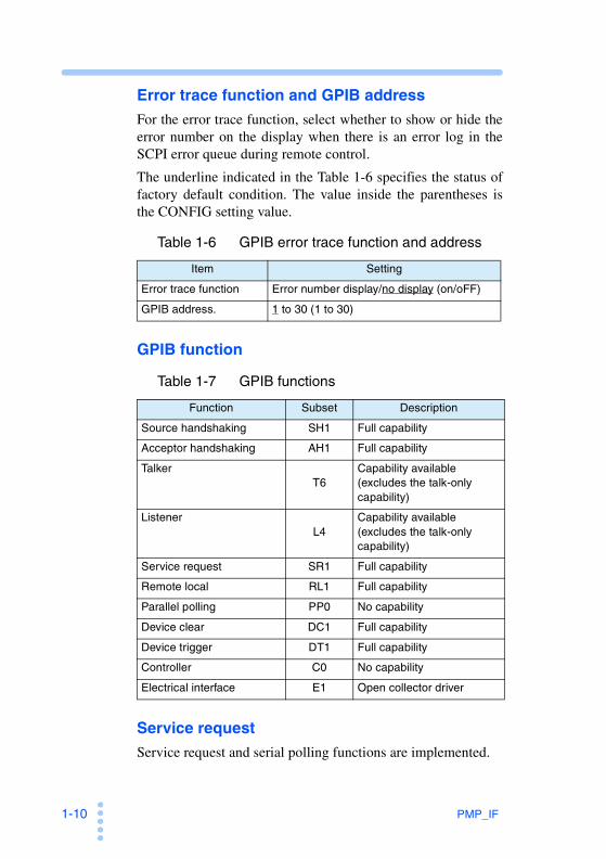
Error trace function and GPIB address
For the error trace function, select whether to show or hide the error number on the display when there is an error log in the SCPI error queue during remote control.
The underline indicated in the Table 1-6 specifies the status of factory default condition. The value inside the parentheses is the CONFIG setting value.
Table 1-6 GPIB error trace function and address
GPIB function
Table 1-7 GPIB functions
Service request
Service request and serial polling functions are implemented.
Item Setting
Error trace function Error number display/no display (on/oFF)
GPIB address. 1 to 30 (1 to 30)
Function Subset Description
Source handshaking SH1 Full capability
Acceptor handshaking AH1 Full capability
TalkerT6
Capability available (excludes the talk-only capability)
ListenerL4
Capability available (excludes the talk-only capability)
Service request SR1 Full capability
Remote local RL1 Full capability
Parallel polling PP0 No capability
Device clear DC1 Full capability
Device trigger DT1 Full capability
Controller C0 No capability
Electrical interface E1 Open collector driver

PMP_IF 1-11
1.4.3 USB Interface
This interface is valid only when the factory option USB inter-face board is installed.
page 1-3
A device driver supporting USB T&M Class (USBTMC) is required to control the PMP through the USB interface. The USBTMC driver is automatically installed by the VISA library.
USB connection
Use a USB cable.
USB configuration
Set the error trace function of USB by carrying out the steps below. You can check the vendor ID and product ID. The volt-meter, ammeter, CONFIG switch, rotary knob, and output dis-play selection switch are used in the configuration.
Table 1-8 CONFIG parameters (USB)
See
Voltmeter Description of the setting or display
ON.PO Power-on output-on setting
TR.CH Tracking setting
SENS Remote sensing setting
VO.LIOperation setting at upper/lower volt-age limit
CU.LIOperation setting at upper/lower cur-rent limit
VO.FI Voltage fine setting
CU.FI Current fine setting
TRAC Error trace function setting
VID Vendor ID display
PID Product ID display

1-12 PMP_IF
PMP Series Operation Manual CONFIG Setup
1. Press the CONFIG switch to show the CONFIG dis-play.
2. Set the error trace (trAc).
For the settings, see Table 1-9.
3. Press the CONFIG switch to return to the normal dis-play.
4. Turn the POWER switch off.
The settings are fixed when the POWER switch is turned off.
Error trace function
This function is to select whether to show or hide the error number on the display when there is an error log in the SCPI error queue during remote control.
The underline indicated in the Table 1-9 specifies the status of factory default condition. The value inside the parentheses is the CONFIG setting value.
Table 1-9 USB error trace function
Service request
Service request and serial polling functions are implemented.
USB function
Complies with USB Specification 2.0.
Complies with USBTMC Specification 1.0 and USBTMC-USB488 Specification 1.0.
Data rate: 12 Mbps maximum (full speed).
Vendor ID (VID): 0x0B3E ( )
Product ID (PID): 0x1011 ( )
See
Item Setting
Error trace function Error number display/no display (on/oFF)

PMP_IF 1-13
1.5 Additional Feature
Interface board
page 2-22
The following feature is available for the optional interface board only when it is operated in the remote control.
• Increased number of memory sets from 3 to 10.
• If operating from the panel, only memories 1 to 3 can be recalled.
See

1-14 PMP_IF
1.6 Overview of Messages
The information that is exchanged between the computer and the PMP is called a message.
The PMP uses the SCPI language for the messages.
There are two types of messages, commands that are sent from computer to the PMP and responses that are sent from the PMP to the computer.
Commands are used to execute functions of the PMP, change settings, and query settings and status. Responses return the set-tings and status of the PMP.
Command hierarchy
SCPI is an ASCII-based command language designed for test and measurement devices. The command hierarchy is struc-tured around the common root or node, which is the construc-tion block of the SCPI sub system. A command consists of a program header, parameters, and punctuations.
The hierarchy is explained using the SOURce subsystem as an example.
A higher node is separated from a lower node using a colon (:).
Program header Parameter Node hierarchy
[SOURce:] Root node
VOLTage 2nd level
[:LEVel] 3rd level
:TRACking 4th level
[:RATio] <numeric> 5th level
CURRent 2nd level
[:LEVel] 3rd level
[:IMMediate] 4th level
[:AMPLitude] <numeric> 5th level
:TRIGgered 4th level
[:AMPLitude] <numeric> 5th level

PMP_IF 1-15
1.6.1 SCPI Command Syntax
Command syntax
This manual denotes SCPI commands using the following for-mat.
(Example)[SOURce:]CURRent[:LEVel][:IMMediate]
[:AMPLitude] {<current>|MINimum|MAXimum}
• There are two forms of SCPI commands, the long form in which the command is written out in its entirety and the short form in which the letters written in lowercase are omit- ted.
SCPI commands can be sent either in the long form or short form.
• SCPI commands are not case sensitive. CURR, Curr, and curr are all accepted as short forms of CURRent.
CURRENT, Current, current are all accepted as long forms.
• A space is required between the program header section and the parameter section.
• Multiple parameters, when available, are concatenated using commas.
• Compound commands can be created by concatenating two commands with a semicolon.
(Example)SOURce:CURRent MINimum;VOLTage MINimum
This compound command is the same as entering the follow-ing two commands.
SOURce:CURRent MINimum
SOURce:VOLTage MINimum
The first command, SOURce:CURRent MINimum, sets the path to SOURce. Therefore, the root node, SOURce, can be omitted in the second command.
An error occurs if a node that is not defined in the current path (except CURRent and VOLTage) is designated.

1-16 PMP_IF
• A colon is required between program headers.
• Commands of different subsystems can be concatenated using colons and semicolons.
(Example)SOURce:CURRent MINimum;:MEASure:CURRent?
This compound command contains two root nodes, SOURce and MEASure.
When the second or subsequent command starts with a colon, the path specified by the previous command is cleared.
• The maximum number of characters that can be transmitted in a single line is 256.
Special symbols and characters
Special symbols and characters used in this manual to describe SCPI commands are defined as indicated in Table 1-10.
Table 1-10 Definitions of special symbols and characters
Query
The device settings or status can be queried.
To make a query, add a question mark at the end of the program header section. If a query has parameters, enter a space after the question mark followed by the parameters.
Symbols or Characters
Description
< >Characters strings inside the < and > symbols indicate program data.Do not include these symbols in the actual program.
{ }Characters and numbers delimited by “|” in braces indi-cate that one of the items is to be selected.Do not include the braces in the actual program.
[ ]
Characters strings inside brackets indicate optional data.When option data is not sent with the program, the default value is sent. Do not include the brackets in the actual program.

PMP_IF 1-17
(Example)CURRent? MIN
• When transmitting two queries in separate lines, read the response to the first query before transmitting the second line. If you send two lines of queries at once, an incom- plete response may be received.
For GPIB or USB, an SCPI error (-410, “Query INTER-RUPTED”) may occur.
String termination
All commands must be terminated using a valid terminator.
The available terminators are <line feed> (ASCII 0x0A) and EOI (end-or-identify). Either one can be used as a terminator.
Because EOI is not available on the RS232C, be sure to use <line feed>.
When a command string is terminated, the path is reset to the root level.
• CR (ASCII 0x0D) is not a terminator.
Common commands
page 2-2
The IEEE-488.2 and SCPI standards contain a set of common commands for reset, self-test, and other functions. These com-mon commands always start with an asterisk. The commands may have one or multiple parameters.
See

1-18 PMP_IF
1.6.2 Parameters
The parameter format of SCPI is derived from the program parameter format defined in IEEE 488.2.
The representation system of the program data that is used on the PMP is indicated below.
Non-numeric parameters
The PMP uses the following two types of numeric parameters.
Table 1-11 Non-numeric parameters
Symbols or Characters
Description
Characterdata
Used when only a limited number of values is available for the program setting. Responses are returned in the short form. (Example) TRIGger:SOURce {IMMediate|BUS}
Boolean dataExpresses a 1 or 0 condition or an ON or OFF condition. Responses are returned as 1 or 0. (Example) OUTPut {ON|OFF|1|0}

PMP_IF 1-19
Numeric parameters
The PMP uses the following five types of numeric parameters.
Table 1-12 Numeric parameters
Special form numeric parameters
The special form numeric parameters MINimum and MAXi-mum can be used as substitutes for limit values when the parameter is numeric.
In the example below, the current is set to the minimum value.CURRent MINimum
The minimum and maximum values can be inquired for most parameters using queries.
CURRent? MIN
CURRent? MAX
Symbols or Characters
Description
NR1 Represents an integer. *1
*1. Details are given in the IEEE 488.2 Standard Digital Interface for Programmable Instrumentation.
NR2 Represents a real number (floating point). *1
NR3 Represents a real number (exponential).*1
NRf NRf is a generic term that includes NR1, NR2, and NR3.
Numeric
Represents a decimal point, optional sign, and measure-ment unit.The numeric representation syntax is the same as NRf.MINimum and MAXimum are available as substitutes for declaring certain values.Units such as V, A, and S can also be used in a numeric parameter.If a value that cannot be assigned is entered, the device rounds the value to the closest possible value. (Example) SOURce:CURRent:TRACking 300The range of values for SOUR:CURR:TRAC is 0 to 200. Thus, 200 is set even if 300 is specified.

1-20 PMP_IF
Measurement unit
Below are the default measurement units.
• V (voltage) • A (current) • S (second)
• PCT (percent)
The following optional prefixes are supported.
•M (milli) • U (micro)
• In accordance with the International System of Units, the unit symbols contain lowercase characters. The IEEE standard uses uppercase characters. SCPI commands are not case sensitive.
• Commands are accepted even if measurement units are not specified.
• To enter “µ” in the data, use “U” instead.

PMP_IF 1-21
1.7 Command Description in This Manual
This manual describes the commands in the following manner.
Table 1-13 Command items and reference pages
CURR
Sets the current. Set the channel using INST/INST:NSEL.
Command
Parameter
Value: 0 to the maximum current of the specified channel (maximum current by default)
Unit: A
When *RST is sent, the value is set as shown in Table 1-14.
Response
Returns the current setting of the specified channel in the NR3 form in response to CURR?. ?
Attach the value you want to specify after the command and send the command. To set the current to 1 A, send CURR 1.
The parameters are listed. In the case of this command, the parameter is numeric. In addition to specifying the desired value, you can specify the minimum or maximum value.
The commands are given in the long form.The lower-case section can be omitted. The section enclosed by braces ([ ]) can also be omitted.
The selectable range is given.Optional symbols such as m and m can also be used.
The unit for the value. The unit can be omitted.
Specify MAX to set the maximum value.
Specify MIN to set the minimum value.
The representation system of the value that is returned when a query is sent.
This command is affected if *RST is sent, and the setting changes to the value indicated in Table 1-14.The current is changed to the maximum current if *RST is sent.
[SOURce:] CURRent [ : IMMediate] [ : AMPLitude]
[ : IMMediate] [ : AMPLitude]
[ : LEVel] { <numeric> | M IN|MAX }
[SOURce:] CURRent [ : LEVel] ? [MIN|MAX]
Item Page
Command syntax 1-15
Parameter 1-18
Unit 1-20
Table 1-14 1-22
Query 1-16
Representation system 1-18
Messages A-2
Errors A-9
Tutorial A-13
Sample programs A-29
See

1-22 PMP_IF
1.8 Default Conditions
page 2-5
Table 1-14 shows how the PMP is set when the *RST com-mand is executed, at the time of factory shipment, and when the power is turned on.
Table 1-14 Conditions after sending a *RST and at power-on
See
Setting
Value
Unit Function*RST
Factory default
At power-on
OUTP 0/OFF 0/OFF 0/OFF*1 – Turns the output on/off.
OUTP:TRAC OFF OFF OFF – Sets the tracking oper-ation.
OUTP:DEL 0/OFF 0/OFF Setting immedi-
ately before turning the POWER
switch off.
– Sets the delay opera-tion on/off setting between channels.
OUTP:PON:STAT RST*2 RST*2 – Output status at power-on.
VOLT 0 0 V Sets the voltage.
VOLT:TRAC 100 100 100 PCT Sets the tracking func-tion 2 voltage.
CURR Maximum current
Maximum current
Setting immediately
before turning the POWER
switch off.
A Sets the current.
CURR:TRAC 100 100 100 PCT Sets the tracking func-tion 2 current.
INST:SEL / INST:NSEL
CH1/1 CH1/1 CH1/1 – Sets the channel to be controlled.
INST:FOC CH1 CH1 Setting immedi-
ately before turning the POWER
switch off.
– Sets the channel to be displayed.
INST:COUP NONE NONE NONE – Sets multiple channels.
OUTP:TRIG 0/OFF 0/OFF 0/OFF – Sets whether to turn the output on/off using a trigger.

PMP_IF 1-23
Setting
Value
Unit Function*RST
Factory default
At power-on
VOLT:TRIG 0 0 0 V Target voltage using a trigger
CURR:TRIG Maximum current
Maximum current
Maximum current
A Target current using a trigger
TRIG:SOUR BUS*3 BUS*3 BUS*3 – Sequence 1 trigger source
TRIG:SEQ2:DEL:ON / TRIG:OUTP:DEL:ON
0 0 Setting immedi-
ately before turning the POWER
switch off.
S Sets the output on delay.
TRIG:SEQ2:DEL:OFF / TRIG:OUTP:DEL:OFF
0 0 S Sets the output off delay.
TRIG:SEQ2:SOUR / TRIG:OUTP:SOUR
BUS*3 BUS*3 BUS*3 – Sequence 2 trigger source
SYST:CONF:TRAC 0/OFF 0/OFF Setting immedi-
ately before turning the POWER
switch off.
– Sets the tracking func-tion.
SYST:CONF:RSEN 0/OFF 0/OFF – Sets the remote sens-ing.
SYST:KLOC No change
OFF – Locks the panel opera-tion.
SYST:TRAC 0/OFF – Sets the debug trace.
*1. The PMP may power up at 1/ON depending on the OUTP:PON:STAT setting.*2. Output on when RST:POWER is on.*3. BUS: Start on a software trigger.

1-24 PMP_IF

Commands
This chapter describes the details of commands and reg- isters.
2Remote Control

2-2 PMP_IF
2.1 IEEE488.2 Common Commands
*CLS
Clears all event registers including the status byte, event status, and error queue.
page 2-39
Command*CLS
*ESE
page 2-43
Sets the event status register that is counted by the event sum-mary bit (ESB) of the status byte.
Command*ESE <NR1>
*ESE?
Parameter
Setting: 0 to 255
An SCPI error (-222, “Data out of range”) occurs if outside the range.
(ex) When *ESE 16 is transmitted, bit 4 of the event status enable register is set. Each time the execution error bit (bit 4) of the event status register is set, the summary bit (ESB) of the status byte is set.
Response
Returns the value of the event status enable register in the NR1 form in response to *ESE?.
See
See
PMP_IF 2-3
Co
mm
and
s (C
om
mo
n C
om
man
ds)
*ESR
page 2-43
Queries the event status register. Registers that are read are cleared.
Command*ESR?
Response
Returns the value of the event status register in the NR1 form in response to *ESR? and clears the register.
*IDN
Queries the model name, serial number, and firmware version of the PMP.
Command*IDN?
Response
The response to *IDN? is indicated below.
(ex) For PMP16-1QU with a serial number AB123456, firm- ware version 1.00, and option firmware version 1.01
Returns KIKUSUI,PMP16-1QU,AB123456,1.00 1.01.
• The option firmware version is 0.00 if the RS232C inter- face board is installed.
See

2-4 PMP_IF
*OPC
Section 12.5.3 in IEEE 488.2-1992
Sets the OPC bit (bit 0) of the event status register when the processing of all commands standing by is complete.
Command
*OPC
*OPC?
Response
Returns 1 when all the commands processing in stand by are completed in response to *OPC?.
*OPT
Queries the option interface board that is installed in the PMP.
Command*OPT?
Response
Returns the interface board that is installed as character data in response to *OPT?.
See

PMP_IF 2-5
Co
mm
and
s (C
om
mo
n C
om
man
ds)
*PSC
Section 10.25 in IEEE 488.2-1992
Sets whether to clear the event status enable register and the service request enable register when the POWER switch is turned on (power-on status).
Command*PSC {0|1}
*PSC?
Parameter
Setting: 0 Does not clear the *ESE and *SRE set- tings when the POWER switch is turned on.
1 Clears the *ESE and *SRE settings when the POWER switch is turned on.
An SCPI error (-222, “Data out of range”) occurs if outside the range.
(ex) To enable the power-on SRQ function
*PSC 0;*SRE 32;*ESE 128
Response
Returns the power-on status setting in the NR1 form in response to *PSC?
*RST
page 1-22
Aborts the measurement operation and initializes the PMP to factory default condition.
For the commands that are affected by *RST, see Table 1-14.
Command*RST
See
See

2-6 PMP_IF
*SRE
Sets the service request enable register.
The service request enable register is used to select the sum-mary messages in the status byte register that will be able to perform service requests.
To clear the service request enable register, send *SRE 0. If the register is cleared, service requests cannot be generated by sta-tus information.
Command*SRE <NR1>
*SRE?
Parameter
Setting: 0 to 255
An SCPI error (-222, “Data out of range”) occurs if outside the range.
(ex) Sending *SRE 8 sets bit 3 of the service request enable register. Each time the summary bit (bit 3) of the QUES- tionable status register in the status byte is set, a service request message is generated.
Response
Returns the value of the service request enable register in the NR1 form in response to *SRE?.

PMP_IF 2-7
Co
mm
and
s (C
om
mo
n C
om
man
ds)
*STB
page 2-41
Queries the contents of the status byte register and the MSS (master summary status) message.
The response is the same as serial polling only with the excep-tion that the MSS message appears in place of the RQS mes-sage in bit 6.
Command*STB?
Response
Returns the value of the status byte register and the MSS mes-sage (bit 6) in NR1 form in response to *STB?.
*TRG
Section 10.37 in IEEE 488.2-1992
Trigger command.
This is a substitute command for the IEEE488.1 get message (Group Execute Trigger).
This command applies a software trigger to all sequence groups.
If the PMP is not in a condition to accept triggers, an SCPI error (-211,“Trigger ignored”) occurs.
Command*TRG
*TST
Section 10.38 in IEEE 488.2-1992
This command is for executing a self-test, but the PMP is not equipped with this feature.
Command*TST?
Response
Always returns 0 in response to *TST?.
See
See
See

2-8 PMP_IF
*WAI
Prevents the PMP from executing subsequent commands until all operations in standby are complete.
Command*WAI

PMP_IF 2-9
Co
mm
and
s (O
utp
ut
Set
tin
g)
2.2 Output Setting
OUTP
Turn the output on/off.
If the delay output operation is set to on or off, the output turns on or off after the specified time elapses.
page 2-10 page 2-29 page 2-30
Set the output delay operation using OUTP:DEL, TRIG:SEQ2 :DEL:ON / TRIG:OUTP:DEL:ON or TRIG:SEQ2:DEL:OFF / TRIG:OUTP:DEL:OFF.
CommandOUTPut[:STATe][:IMMediate] {ON|OFF|1|0}
OUTPut[:STATe][:IMMediate]?
Parameter
Setting: ON(1) Output on
OFF(0) Output off (default)For the setting that is applied when *RST is sent, see Table 1-14.
Response
Returns the output status in the NR1 form in response to OUTP?.
See

2-10 PMP_IF
OUTP:PON:STAT
Sets the output state at power-on.
CommandOUTPut:PON:STATe {RST|AUTO}
OUTPut:PON:STATe?
Parameter
Setting: RST Output off at power-on (default)
AUTO Output on at power-onFor the setting that is applied when *RST is sent, see Table 1-14.
Response
Returns the output state at power-on as character data in response to OUTP:PON:STAT?.
OUTP:DEL
PMP Series Operation Manual Delay Function
Sets the delay operation for turning on or off the output.
You can also set the output delay operation in sequence 2.
Set the delay time using TRIG:SEQ2:DEL:ON / TRIG:OUTP :DEL:ON or TRIG:SEQ2:DEL:OFF / TRIG:OUTP:DEL:OFF.
CommandOUTPut:DELay[:STATe] {ON|OFF|1|0}
OUTPut:DELay[:STATe]?
Parameter
Setting: ON(1) Delay operation on
OFF(0) Delay operation off (default)For the setting that is applied when *RST is sent, see Table 1-14.
Response
Returns the delay operation setting in the NR1 form in response to OUTP:DEL?.
See

PMP_IF 2-11
Co
mm
and
s (O
utp
ut
Set
tin
g)
OUTP:TRAC
Sets the output tracking operation.
If tracking function 1 is set, the channel specified using INST / INST:NSEL becomes the reference channel and reference value.
CommandOUTPut:TRACking[:MODE] {OFF|RAT|ABS}
OUTPut:TRACking[:MODE] ?
Parameter
Setting: OFF Tracking operation off (default)
ABS Tracking function 1 (absolute change)
RAT Tracking function 2 (proportional change)
For the setting that is applied when *RST is sent, see Table 1-14.
Response
Returns the tracking operation setting as character data in response to OUTP:TRAC?.

2-12 PMP_IF
Voltage Settings
VOLT
Sets the voltage.
page 2-18
Set the channel using INST / INST:NSEL.
Command[SOURce:]VOLTage[:LEVel][:IMMediate]
[:AMPLitude] {<numeric>|MIN|MAX}
[SOURce:]VOLTage[:LEVel][:IMMediate] [:AMPLitude]? {MIN|MAX}
Parameter
Setting: 0 to the maximum voltage of the specified channel (zero by default)
Unit: VFor the setting that is applied when *RST is sent, see Table 1-14.
Response
Returns the voltage setting of the specified channel in the NR3 form in response to VOLT?.
See

PMP_IF 2-13
Co
mm
and
s (O
utp
ut
Set
tin
g)
VOLT:TRAC
Sets the ratio of the voltage change for the tracking function 2.
Set the channel using SYST:CONF:TRAC.
Send OUTP:TRAC RAT to specify tracking function 2 before sending VOLT:TRAC.
Command[SOURce:]VOLTage[:LEVel]:TRACking[:RATio]
{<numeric>|MIN|MAX}
[SOURce:]VOLTage[:LEVel]:TRACking[:RATio]? [MIN|MAX]
Parameter
Setting: 0.0 to 200.0 (default: 100.0)
Unit: PCTFor the setting that is applied when *RST is sent, see Table 1-14.
Response
Returns the ratio of change for the tracking function 2 in the NR3 form in response to VOLT:TRAC?.

2-14 PMP_IF
Current Settings
CURR
Sets the current.
page 2-18
Set the channel using INST / INST:NSEL.
Command[SOURce:]CURRent[:LEVel][:IMMediate]
[:AMPLitude] {<numeric>|MIN|MAX}
[SOURce:]CURRent[:LEVel][:IMMediate] [:AMPLitude]? [MIN|MAX]
Parameter
Setting: 0 to the maximum current of the specified channel (maximum current by default)
Unit: AFor the setting that is applied when *RST is sent, see Table 1-14.
Response
Returns the current setting of the specified channel in the NR3 form in response to CURR?.
See

PMP_IF 2-15
Co
mm
and
s (O
utp
ut
Set
tin
g)
CURR:TRAC
Sets the ratio of the current change for the tracking function 2.
Set the channel using SYST:CONF:TRAC.
Send OUTP:TRAC RAT to specify tracking function 2 before sending CURR:TRAC.
Command[SOURce:]CURRent[:LEVel]:TRACking[:RATio]
{<numeric>|MIN|MAX}
[SOURce:]CURRent[:LEVel]:TRACking[:RATio]? [MIN|MAX]
Parameter
Setting: Value: 0.0 to 200.0 (default: 100.0)
Unit: PCTFor the setting that is applied when *RST is sent, see Table 1-14.
Response
Returns the ratio of change for the tracking function 2 in the NR3 form in response to CURR:TRAC?.

2-16 PMP_IF
2.3 Measurement Operation Settings
The response data is always generated using the latest mea-sured values.
MEAS and READ perform the same operations.
MEAS:VOLT / READ:VOLT
Queries the measured value of the voltage output.
page 2-21
To query the measured values of multiple channels simulta-neously, use the INST:COUP command.
CommandMEASure[:SCALar]:VOLTage[:DC]?
READ[:SCALar]:VOLTage[:DC]?
Response
Returns the measured value of the voltage output in the NR3 form in response to MEAS:VOLT? / READ:VOLT?.
If multiple channels are specified, the measured values are returned in ascending order by channel number with a comma separating each value.
MEAS:CURR / READ:CURR
Queries the measured value of the current output.
page 2-21
To query the measured values of multiple channels simulta-neously, use the INST:COUP command.
CommandMEASure[:SCALar]:CURRent[:DC]?
READ[:SCALar]:CURRent[:DC]?
Response
Returns the measured value of the current output in the NR3 form in response to MEAS:CURR? / READ:CURR?.
If multiple channels are specified, the measured values are returned in ascending order by channel number with a comma separating each value.
See
See

PMP_IF 2-17
Co
mm
and
s (C
lear
ing
th
e A
larm
)
2.4 Clearing the Alarm
OUTP:PROT:CLE
Clears the alarm.
CommandOUTPut:PROTection:CLEar
• When the alarm signal is applied by the external contact, the output can be shut off, however, the alarm signal may not be generated if the time for the short-circuit of contact is less than 0.5 s. In this case, this command can not clear the function com- pletely. Therefore, turn off the POWER switch once.
CAUTION

2-18 PMP_IF
2.5 Setting the Channels
Specifies settings related to the channel function.
INST / INST:NSEL
Sets the channel for applying the commands using a channel name or channel number.
INST / INST:NSEL only applies to commands, but not to change for the channel displayed on the panel. To select the channel for applying both the commands and the channel shown on the panel display at the same time as with the output display selection switch, you must send the INST:FOC com-mand along with this command.
If you execute the command while tracking function 1 is in operation, the channel specified with this command becomes the reference channel. The amount of change is cleared, and the value at that point becomes the reference value.
CommandINSTrument[:SELect] {CH1|CH2|CH3|CH4}
INSTrument[:SELect]?
INSTrument:NSELect {1|2|3|4}
INSTrument:NSELect?
Parameter (INST)
Setting: CH1 Apply the commands to channel 1 (default)
CH2 Apply the commands to channel 2
CH3 Apply the commands to channel 3
CH4 Apply the commands to channel 4 (4-output model only)
Parameter (INST:NSEL)
Setting: 1 Apply the commands to channel 1 (default)
2 Apply the commands to channel 2
3 Apply the commands to channel 3
4 Apply the commands to channel 4 (4-output model only)

PMP_IF 2-19
Co
mm
and
s (S
etti
ng
th
e C
han
nel
s)
Response
Returns the channel for applying the commands as character data in response to INST?.
Returns the channel for applying the commands in the NR1 form in response to INST:NSEL?.

2-20 PMP_IF
INST:FOC
Sets the channel displayed on the panel.
CommandINSTrument[:SELect]:FOCus {CH1|CH2|CH3|CH4}
INSTrument[:SELect]:FOCus?
Parameter
Setting: CH1 Display channel 1 on the panel (default)
CH2 Display channel 2 on the panel
CH3 Display channel 3 on the panel
CH4 Display channel 4 on the panel (4-output model only)
Response
Returns the channel displayed on the channel as character data in response to INST:FOC?.

PMP_IF 2-21
Co
mm
and
s (S
etti
ng
th
e C
han
nel
s)
INST:COUP
Specifies the applicable channels when applying the commands to the plural number of channels.
Commands that can be applied are MEAS:CURR / READ:CURR and MEAS:VOLT / READ:VOLT.
Be sure to execute INST:COUP at the same time as INST or INST:NSEL.
If channels specified by INST or INST:NSEL are not included in the channels specified by INST:COUP, commands will not be applied to multiple channels.
CommandINSTrument:COUPle {<list>|ALL|NONE}[,<list>][,<list>][,<list]
INSTrument:COUPle?
Parameter
<list> is a collective term that includes CH1, CH2, CH3, and CH4.
Setting: CH1 to CH4 Specify any channels between channel 1 and channel 4 (CH4 available only on the 4-output model)
ALL Specify all
NONE Not specify (default)
(ex) To apply the commands to CH1 and CH3INST CH1
INST:COUP CH1,CH3
Response
Returns the setting for applying the commands to multiple channels as character data in response to INST:COUP?.

2-22 PMP_IF
2.6 Memory Function
This section explains the commands related to the memory functions of the PMP.
MEM:SAV
Saves the present voltage, current, and delay time settings of the PMP to the memory.
MEMory:SAV <NRf>
Setting: 1 to 10
(4 to 10 available only during remote control)
An SCPI error (-222, “Data out of range”) occurs if outside the range.
MEM:RCL
Recall the memory value.
The memory value cannot be recalled while the delay function is in operation.
CommandMEMory:RCL <NRf>
Setting: 1 to 10
(4 to 10 available only during remote control)
An SCPI error (-222, “Data out of range”) occurs if outside the range.

PMP_IF 2-23
Co
mm
and
s (T
rig
ger
Fu
nct
ion
)
2.7 Trigger Function
Specifies settings related to the trigger function.
Setting the trigger
The trigger is classified into two sequence groups, TRIGger[:SEQuence[1]] and TRIGger:SEQuence2.
There are two second level nodes for each sequence in the TRIGger subsystem. The same operation is carried out regard-less of the node that is used.
■ Sequence 1
TRIGger subsystem that changes the settings
Second level node: SEQuence[1] or TRANsient
■ Sequence 2
A TRIGger subsystem for the output on/off delay
Second level node: SEQuence2 or OUTPut

2-24 PMP_IF
2.7.1 Setting Changes (Sequence 1: TRANsient Settings)
page A-20
The sequence 1 group can synchronize the output changes using triggers.
When ABOR is sent, INIT:SEQ1 is cancelled. The VOLT:TRIG setting does not change.
If the voltage (VOLT) is changed, the voltage setting that is applied with a trigger is cancelled and it will be overwritten to the setting value. Table 2-1 shows the responses when the volt-age is set to 2 V (VOLT 2) and when the voltage setting that is applied with a trigger is set to 1 V (VOLT:TRIG 1).
Table 2-1 Responses after sending VOLT 2;:VOLT:TRIG 1
See
Response
VOLT? VOLT:TRIG?
Immediately after the set-ting
2 1
After a trigger is sent 1 1
After *RST is sent 0 0
ABOR is sent before send-ing a trigger
2 2 (cancel)
Voltage change VOLT 3 is sent before sending a trig-ger
3 3 (cancel)

PMP_IF 2-25
Co
mm
and
s (T
rig
ger
Fu
nct
ion
)
TRIG:SOUR
Sets the condition (trigger source) for the practical change of setting after the sequence 1 group receives INIT:SEQ1 / INIT:NAME TRAN.
CommandTRIGger[:SEQuence[1]]:SOURce {IMMediate|BUS}
TRIGger[:SEQuence[1]]:SOURce?
TRIGger[:TRANsient]:SOURce {IMMediate|BUS}
TRIGger[:TRANsient]:SOURce?
Parameter
Setting: IMM Starts the setting immediately
BUS Wait for a software trigger (*TRG, TRIG, or IEEE488.1 get (Group Execute Trig- ger)) to change the setting (default)
For the setting that is applied when *RST is sent, see Table 1-14.
Response
Returns the trigger source of the sequence 1 group as character data in response to TRIG:SOUR?.

2-26 PMP_IF
VOLT:TRIG
Sets the voltage that is applied when INIT:SEQ1 / INIT:NAME TRAN and a software trigger are sent.
page 2-18
Set the channel using INST / INST:NSEL.
Command[SOURce:]VOLTage[:LEVel]:TRIGgered
[:AMPLitude] {<numeric>|MIN|MAX}
[SOURce:]VOLTage[:LEVel]:TRIGgered [:AMPLitue]? [MIN|MAX]
Parameter
Setting: 0 to the maximum voltage of the specified channel (zero by default)
Unit: VFor the setting that is applied when *RST is sent, see Table 1-14.
Response
Returns the voltage value that is applied when a trigger is received in the NR3 form in response to VOLT:TRIG?.
CURR:TRIG
Sets the current value that is applied when INIT:SEQ1 / INIT:NAME TRAN and a software trigger are sent.
page 2-18
Set the channel using INST / INST:NSEL.
Command[SOURce:]CURRent[:LEVel]:TRIGgered
[:AMPLitude] {<numeric>|MIN|MAX}
[SOURce:]CURRent[:LEVel]:TRIGgered [:AMPLitude]? [MIN|MAX]
Parameter
Setting: 0 to the maximum current of the specified channel (maximum current by default)
Unit: AFor the setting that is applied when *RST is sent, see Table 1-14.
Response
Returns the current value that is applied when a trigger is received in the NR3 form in response to CURR:TRIG?.
See
See

PMP_IF 2-27
Co
mm
and
s (T
rig
ger
Fu
nct
ion
)
Starting the trigger function (sequence 1)
INIT / INIT:NAME TRAN
Starts the trigger function of the sequence 1 group.
If TRIG:SOUR is set to IMM, the change starts immediately. If set to BUS, the change starts after waiting for a software trig-ger.
CommandINITiate[:IMMediate][:SEQuence[1]]
INITiate[:IMMediate]:NAME TRANsition
TRIG
Applies a software trigger to the sequence 1 group.
CommandTRIGger[:SEQuence[1]][:IMMediate]
TRIGger[:TRANsient][:IMMediate]
2-28 PMP_IF
2.7.2 Output On/Off Delay Function (Sequence 2: OUTPUT Settings)
page A-22
The sequence 2 group enables the output on/off delay to be controlled with triggers.
OUTP:TRIG
Sets whether to turn the output on or off when a trigger is applied.
page 2-32
The actual operation is executed using INIT:SEQ2 / INIT:NAME OUTP. The delay time is set using TRIG:SEQ2:DEL:ON / TRIG :OUTP:DEL:ON or TRIG:SEQ2:DEL:OFF / TRIG:OUTP:DEL :OFF.
CommandOUTPut[:STATe]:TRIGgered {ON|OFF|1|0}
OUTPut[:STATe]:TRIGgered?
Setting: ON(1) Turn the output no when a trigger is applied
OFF(0) Turn the output off when a trigger is applied (default)
For the setting that is applied when *RST is sent, see Table 1-14.
Response
Returns whether the output is turned on or off when a trigger is applied in the NR1 form in response to OUTP:TRIG?.
See
See

PMP_IF 2-29
Co
mm
and
s (T
rig
ger
Fu
nct
ion
)
TRIG:SEQ2:DEL:ON / TRIG:OUTP:DEL:ON
page 2-18
Sets the delay for turning on the output.
Set the channel using INST / INST:NSEL.
CommandTRIGger:SEQuence2:DELay:ON
{<numeric>|MIN|MAX}
TRIGger:SEQuence2:DELay:ON?
TRIGger:OUTPut:DELay:ON {<numeric>|MIN|MAX}
TRIGger:OUTPut:DELay:ON?
Parameter
Setting: 0.0 to 99.9 0 is no delay (The default value is 0.0)
Unit: SFor the setting that is applied when *RST is sent, see Table 1-14.
(ex) When the delay until the CH1 output turns on is 0.5 sec- ondsINST CH1
TRIG:OUTP:DEL:ON 0.5
Response
Returns the delay time until the output is turned on in the NR3 form in response to TRIG:SEQ2:DEL:ON? / TRIG:OUTP :DEL:ON?.
See

2-30 PMP_IF
TRIG:SEQ2:DEL:OFF / TRIG:OUTP:DEL:OFF
page 2-18
Sets the delay for turning off the output.
Set the channel using INST / INST:NSEL.
CommandTRIGger:SEQuence2:DELay:OFF
{<numeric>|MIN|MAX}
TRIGger:SEQuence2:DELay:OFF?
TRIGger:OUTPut:DELay:OFF {<numeric>|MIN|MAX}
TRIGger:OUTPut:DELay:OFF?
Parameter
Setting: 0.0 to 99.9 0 is no delay (The default value is 0.0)
Unit: SFor the setting that is applied when *RST is sent, see Table 1-14.
(ex) When the delay until the CH2 output turns off is 1.5 sec- ondsINST CH2
TRIG:OUTP:DEL:OFF 1.5
Response
Returns the delay until the output is turned off in the NR3 form in response to TRIG:SEQ2:DEL:OFF? / TRIG:OUTP:DEL:OFF?
See

PMP_IF 2-31
Co
mm
and
s (T
rig
ger
Fu
nct
ion
)
TRIG:SEQ2:SOUR / TRIG:OUTP:SOUR
Sets the condition (trigger source) for the practical start of the delay action after the sequence 2 group receives INIT:SEQ2 / INIT:NAME OUTP.
CommandTRIGger:SEQuence2:SOURce {IMMediate|BUS}
TRIGger:OUTPut:SOURce {IMMediate|BUS}
TRIGger:SEQuence2:SOURce?
TRIGger:OUTPut:SOURce?
Parameter
Setting: IMM Start the delay action immediately
BUS Wait for a software trigger (*TRG, TRIG:SEQ2, or IEEE488.1 get (Group Execute Trigger)) to start the delay action
For the setting that is applied when *RST is sent, see Table 1-14.
Response
Returns the trigger source of the sequence 2 group as character data in response to TRIG:SEQ2:SOUR? / TRIG:OUTP:SOUR?.

2-32 PMP_IF
Starting the trigger function (sequence 2)
INIT:SEQ2 / INIT:NAME OUTP
Starts the trigger function of the sequence 2 group.
If TRIG:SEQ2:SOUR or TRIG:OUTP:SOUR is set to IMM, the delay action starts immediately. If it is set to BUS, the delay action starts after waiting for a software trigger.
CommandINITiate[:IMMediate]:SEQuence2
INITiate[:IMMediate]:NAME OUTPut
TRIG:SEQ2 / TRIG:OUTP
Applies a software trigger to the sequence 2 group.
CommandTRIGger:SEQuence2[:IMMediate]
TRIGger:OUTPut[:IMMediate]

PMP_IF 2-33
Co
mm
and
s (T
rig
ger
Fu
nct
ion
)
2.7.3 Aborting the Operation
Aborts the operation in all sequence groups.
ABOR
Aborts operations such as setting and change in all sequence groups.
The status of trigger after the power is immediately turned on is the same as the condition when the ABOR command is sent.
If ABOR is sent while the sequence 2 group (output on/off delay) is in operation, the output on/off status returns to the sta-tus before the sequence 2 group was started.
The output turns off while the output on delay is in progress. The output turns on while the output off delay is in progress.
A specific sequence group cannot be specified with the ABOR command. It is always interpreted as ALL.
CommandABORt

2-34 PMP_IF
2.8 System Settings
SYST:CONF:TRAC
Sets the channel that performs the tracking operation.
To set the reference channel for tracking function 1, use INST / INST:NSEL. Set the tracking function of the reference channel to be turned on. When the tracking function of the reference channel is turned off, the tracking operation is not performed.
• 3-output modelSYSTem:CONFigure:TRACking[:STATe]
{ON|OFF|1|0},{ON|OFF|1|0},{ON|OFF|1|0}
SYSTem:CONFigure:TRACking[:STATe]?
• 4-output modelSYSTem:CONFigure:TRACking[:STATe]
{ON|OFF|1|0},{ON|OFF|1|0},{ON|OFF|1|0}, {ON|OFF|1|0}
SYSTem:CONFigure:TRACking[:STATe]?
Parameter
Setting: ON(1) Tracking operation on
OFF(0) Tracking operation off (default)
(ex) If the tracking operation of CH1, CH2, and CH3 on a 3- output model is off, on, and on, respectivelySYST:CONF:TRAC 0,1,1
Response
Returns the on/off states of the tracking operation in ascending order by channel number separated by commas in the NR1 form in response to SYSTem:CONFigure:TRACking[:STATe]?.

PMP_IF 2-35
Co
mm
and
s (S
yste
m S
etti
ng
s)
SYST:CONF:RSEN
Sets the channel that performs the sensing operation.
Command
• 3-output modelSYSTem:CONFigure:RSENsing[:STATe]
{ON|OFF|1|0},{ON|OFF|1|0},{ON|OFF|1|0}
SYSTem:CONFigure:RSENsing[:STATe]?
• 4-output modelSYSTem:CONFigure:RSENsing[:STATe]
{ON|OFF|1|0},{ON|OFF|1|0},{ON|OFF|1|0}, {ON|OFF|1|0}
SYSTem:CONFigure:RSENsing[:STATe]?
Parameter
Setting: ON(1) Sensing operation on
OFF(0) Sensing operation off (default)
(ex) If the sensing operation of CH1, CH2, CH3, and CH4 on a 4-output model is on, off, on, and off, respectivelySYST:CONF:RSEN 1,0,1,0
Response
Returns the on/off states of the sensing operation in ascending order by channel number separated by commas in the NR1 form in response to SYSTem:CONFigure:RSENsing[:STATe]?.

2-36 PMP_IF
SYST:TRAC
Sets the status whether to display or not to display of the com-munication errors by performing a debug trace. If the error trace function is turned on, error codes (example: Err-100) are shown on the PMP display.
CommandSYSTem:TRACe {ON|OFF|1|0}
SYSTem:TRACe?
Parameter
Setting: ON(1) Error trace function on
OFF(0) Error trace function off (default)
Response
Returns the on/off setting of the debug trace function in the NR1 form in response to SYSTem:TRACe?.
SYST:ERR
Reads the oldest error information or the event information from the error queue. The error queue can store up to 255 errors.
The error queue is cleared using the *CLS command.
CommandSYSTem:ERRor[:NEXT]?
Response
Returns the oldest error or the event information in the error/event queue in response to SYST:ERR? as follows:
(ex) If there is no error or eventReturns 0, "No error".
(ex) If a command that cannot be executed in the current operat- ing condition is receivedReturns -221, "Settings conflict".

PMP_IF 2-37
Co
mm
and
s (S
yste
m S
etti
ng
s)
SYST:KLOC
Sets or releases the panel operation lock.
CommandSYSTem:KLOCk {ON|OFF|1|0}
SYSTem:KLOCk?
Parameter
Setting: ON (1) Lock the panel operation
OFF (0) Release the panel operation lock (default)
Response
Returns the panel operation lock setting in the NR1 form in response to SYST:KLOCk?.
SYST:LOC (RS232C and USB only)
Sets the PMP operation to local mode (panel operation). This is a substitute command for the IEEE488.1 REN message (Remote Disable).
SYST:REM or SYST:RWL is used to return to remote mode.
CommandSYSTem:LOCal
SYST:REM (RS232C and USB only)
Sets the PMP operation to remote mode. All panel operations except the LOCAL switch are locked. This is a substitute com-mand for the IEEE488.1 REN message (Remote Enable) and address designation.
SYST:LOC is used to return to local mode.
CommandSYSTem:REMote

2-38 PMP_IF
SYST:RWL (RS232C and USB only)
Sets the PMP operation to remote mode. All panel operations are locked (the LOCAL switch is also locked). This is a substi-tute command for the IEEE488.1 llo message (Local Lock Out).
SYST:LOC is used to return to local mode.
CommandSYSTem:RWLock
SYST:VERS
Queries the version of the SCPI specifications to which the PMP conforms.
CommandSYSTem:VERSion?
Response
Always returns 1999.0 in response to SYST:VERS?.

PMP_IF 2-39
Co
mm
and
s (S
tatu
s)
2.9 Status Register and Status Report Function
IEEE488.2 and SCPI registers are used for the status reports.
In each SCPI status register, there are sub registers, CONDition register, EVENt register, ENABle register, PTRansition filter, and NTRansition filter.
Fig. 2-1 shows the SCPI status register structure. The character “+” represents the logic sum of the register bits. Table 2-1 to Table 2-4 describe the bit number, bit weight, and the meaning of each bit.
CONDition register
The CONDition register transits automatically and reflects the condition of the PMP in real-time. Even when this register is read, it does not affect the contents.
EVENt register
The EVENt register bits are automatically set according to the changes in the CONDition register. The rule varies depending on the positive and negative transition filters (PTRansition and NTRansition). The EVENt register is reset when it is read.
ENABle register
The ENABle register enables the reports to the summary bit or status bit of the event bit.
Transition filter
By using the PTRansition (positive transition) filter, it enables to report the events when the condition changes from false to true.
By using the NTRansition (negative transition) filter, it enables to report the events when the condition changes from true to false.
Status

2-40 PMP_IF
When both the positive filter and the negative filter are set to true, the events can be reported each time the status changes.
If both filters are cleared, reporting the event becomes disabled.
Fig. 2-1 Status register
Partially changed SCPI Standard 1999.0 Volume1 fig.9-1.
1999 SCPI Syntax & Style
NOT USEDShutdown Alarm
NOT USED
CH1 CC
CH1 Over Voltage Protection CH2 Over Voltage ProtectionCH3 Over Voltage ProtectionCH4 Over Voltage ProtectionOver Temperature Protection
NOT USED
NOT USED
NOT USEDNOT USEDNOT USED
NOT USED
NOT USEDNOT USED
CH1 CVCH2 CVCH3 CVCH4 CV
NOT USEDWaiting for TRIGger
NOT USEDNOT USED
CH2 CCCH3 CCCH4 CC
ON/OFF DELayNOT USEDNOT USEDNOT USED
Operation CompleteRequest Control
Query ErrorDevice Dependent Error
Command ErrorReserved
Execution Error
Power On
QUEStionable Status Error/Event Queue
OPERation Status
Standard EventStatus Register
StatusByte
Summary of IEEE 488.2 Status Structure Registers
Available to designerAvailable to designer
MAV
RQS
01234567
01234567
0123456789
101112131415
0123456789
101112131415

PMP_IF 2-41
Co
mm
and
s (S
tatu
s)
2.9.1 IEEE488.2 Register Model
Status byte register
The status byte register stores STB and RQS (MSS) messages as defined by the IEEE488.1 standard. The status byte register can be read using IEEE488.1 serial polling or IEEE488.2 com-mon command *STB?.
When the serial polling is carried out, bit 6 responds with the request service (RQS). The status byte value is not changed by the serial polling.
*STB? makes the device transmit the contents of the status byte register and the master status summary (MSS) message.
*STB? does not change the status byte, MSS, and RQS.

2-42 PMP_IF
Table 2-1 Status byte register
BitBit
WeightBit Name Description
0 1 Reserved Reserved for future use by the IEEE488. The bit value is notified as zero.1 2 Reserved
2 4Error/Event Queue If data exists in the error or event queue, this
bit is set to true.
3 8
Questionable Sta-tus Register (QUES)
This bit is set to true when a bit is set in the QUEStionable event status register and the corresponding bit in the QUEStionable status enable register is true.
4 16
Message Available (MAV)
This bit is set to true when a request is received from the digital programming inter-face and the PMP is ready to output the data byte.
5 32Standard Event Status Bit Summary (ESB)
This bit is set to true when a bit is set in the event status register.
6 64
Request Service (RQS)
This bit is set to true when a bit is set in the service request enable register, and the cor-responding bit exists in the status byte.The SRQ line of the GPIB is set.
Master Status Sum-mary (MSS)
This bit is set to true when any of the bits in the status byte register is set to 1 and the cor-responding bit in the service request enable register is set to 1.
7 128
Operation Status Register (OPER)
This bit is set to true when a bit is set in the OPERation event status register and the cor-responding bit in the OPERation status enable register is set.
8-15 – NOT USED –

PMP_IF 2-43
Co
mm
and
s (S
tatu
s)
Event status register
The event status register bits are set when certain events occur during PMP operation. All bits of the event status register are set by the error event queue.
The register is controlled by common commands *ESE, *ESE?, and *ESR? as defined by the IEEE488.2 standard.
Table 2-2 Standard event status register
BitBit
WeightBit Name Description
0 1Operation Com-plete (OPC)
Set when an *OPC command is received and all operations in standby are completed.
1 2Request Control (RQC)
Not used
2 4
Query Error (QYE) Set when an attempt is made to read data from the output queue when there is no output or the error queue is in wait status.Indicates that there is no data in the error queue.
3 8Device Dependent Error (DDE)
Set when there is a device-specific error.
4 16
Execution Error (EXE)
Set when the PMP evaluates the program data following the header is outside the formal input range or does not match the perfor-mance of the PMP.This indicates that a valid SCPI command may not be executed correctly depending on the conditions of the PMP.
5 32
Command Error (CME)
Set when an IEEE 488.2 syntax error is detected, when an unidentifiable header is received, or when a group execution trigger (*TRG) enters the internal IEEE 488.2 SCPI command input buffer.
6 64 NOT USED –
7 128 Power ON (PON) Set when the power is turned on.
8-15 – NOT USED –

2-44 PMP_IF
2.9.2 SCPI Register Model
OPERation status register
The OPERation status register is a 16-bit register which con-tains information about conditions sa the part of normal opera-tion of the PMP.
Table 2-3 OPERation status register (STATus:OPERation)
BitBit
WeightBit Name Description
0 1 CH1 CV CH1 CV output
1 2 CH2 CV CH2 CV output
2 4 CH3 CV CH3 CV output
3 8 CH4 CV CH4 CV output
4 16 NOT USED –
5 32Waiting for TRIG-ger
Indicates whether the PMP is waiting for a trigger.
6 64 NOT USED –
7 128 NOT USED –
8 256 CH1 CC CH1 CC output
9 512 CH2 CC CH2 CC output
10 1024 CH3 CC CH3 CC output
11 2048 CH4 CC CH4 CC output
12 4096ODEL (ON/OFF DELay)
Indicates whether the output delay operation is in progress.
13 8192 NOT USED –
14 16384 NOT USED –
15 32768 NOT USED –

PMP_IF 2-45
Co
mm
and
s (S
tatu
s)
STAT:OPER
Queries the event of the OPERation status register.
A query clears the contents of the register.
CommandSTATus:OPERation[:EVENt]?
Response
Returns the event of the OPERation status register in the NR1 form.
STAT:OPER:COND
Queries the condition of the OPERation status register.
A query does not clear the contents of the register.
CommandSTATus:OPERation:CONDtion?
Response
Returns the condition of the OPERation status register in the NR1 form.
STAT:OPER:ENAB
Sets the enable register of the OPERation status register.
CommandSTATus:OPERation:ENABle <NRf>
STATus:OPERation:ENABle?
Parameter
Setting: 0 to 32767
Response
Returns the enable register of the OPERation status register in the NR1 form.

2-46 PMP_IF
STAT:OPER:PTR
Sets the positive transition of the OPERation status register.
CommandSTATus:OPERation:PTRansition <NRf>
STATus:OPERation:PTRansition?
Parameter
Setting: 0 to 32767
Response
Returns the positive transition of the OPERation status register in the NR1 form.
STAT:OPER:NTR
Sets the negative transition of the OPERation status register.
CommandSTATus:OPERation:NTRansition <NRf>
STATus:OPERation:NTRansition?
Parameter
Setting: 0 to 32767
Response
Returns the negative transition of the OPERation status register in the NR1 form.

PMP_IF 2-47
Co
mm
and
s (S
tatu
s)
QUEStionable status register.
The QUEStionable status register is a 16-bit register which contains information related to the questionable events and sta-tus during PMP operation.
These register bits may indicate problems with the measured data of the PMP.
Table 2-4 QUEStionable status register (STATus:QUEStionable)
BitBit
WeightBit Name Description
0 1CH1 OV(Over Voltage Protection) CH1 overvoltage protection
activated
1 2CH2 OV(Over Voltage Protection) CH2 overvoltage protection
activated
2 4CH3 OV(Over Voltage Protection) CH3 overvoltage protection
activated
3 8CH4 OV(Over Voltage Protection) CH4 overvoltage protection
activated
4 16 OT (Over Temperature Protection) Over heat protection activated
5 32 NOT USED –
6 64 NOT USED –
7 128 NOT USED –
8 256 NOT USED –
9 512 NOT USED –
10 1024 NOT USED –
11 2048 SD(Shutdown Alarm)Alarm input by external contact activated
12 4096 NOT USED –
13 8192 NOT USED –
14 16384 NOT USED –
15 32768 NOT USED –

2-48 PMP_IF
STAT:QUES
Queries the event of the QUEStionable status register.
A query clears the contents of the register.
CommandSTATus:QUEStionable[:EVENt]?
Response
Returns the event of the QUEStionable status register in the NR1 form.
STAT:QUES:COND
Queries the condition of the QUEStionable status register.
A query does not clear the contents of the register.
CommandSTATus:QUEStionable:CONDition?
Response
Returns the status of the QUEStionable status register in the NR1 form.
STAT:QUES:ENAB
Sets the enable register of the QUEStionable status register.
CommandSTATus:QUEStionable:ENABle <NRf>
STATus:QUEStionable:ENABle?
Parameter
Setting: 0 to 32767
Response
Returns the enable register of the QUEStionable status register in the NR1 form.

PMP_IF 2-49
Co
mm
and
s (S
tatu
s)
STAT:QUES:PTR
Sets the positive transition of the QUEStionable status register.
CommandSTATus:QUEStionable:PTRansition <NRf>
STATus:QUEStionable:PTRansition?
Parameter
Setting: 0 to 32767
Response
Returns the positive transition of the QUEStionable status reg-ister in the NR1 form.
STAT:QUES:NTR
Sets the negative transition of the QUEStionable status register.
CommandSTATus:QUEStionable:NTRansition <NRf>
STATus:QUEStionable:NTRansition?
Parameter
Setting: 0 to 32767
Response
Returns the negative transition of the QUEStionable status reg-ister in the NR1 form.

2-50 PMP_IF
Preset Status
STAT:PRES
Resets the ENABle, PTRansition, NTRansition filter registers of all status registers (including sub registers) to their default values.
Default values:
STATus:ENABle = 0x0000
STATus:PTRansition = 0x7FFF
STATus:NTRansition = 0x0000
CommandSTATus:PRESet

The appendix contains lists of messages, lists of com- mand errors, tutorials, sample programs, and interface specifications.
Appendix

A-2 PMP_IF
A.1 A List of Messages
SCPI command: Command name in the short form
Affected: Yes for commands that are affected by *RST
r/w: Query command (r)/set command (w).
*: 1, 2, and 3 indicate SCPI standard command, command in review, and KIKUSUI original command, respectively.
For default values, see Table 1-14.
Table A-1 INSTrument subsystem
Table A-2 MEASure subsystem | READ susytem
SCPI Command SettingResp. Affected Description r/w *
Program HeaderParam-
eterUnit
INST
[:SEL] charCH1 | CH2 | CH3 | CH4
char YesSets the channel for applying the commands.
r/w 1
:NSEL NRf 1 to 4 NR1 Yes
Sets the channel for applying the commands by channel number.
r/w 1
[:SEL]:FOC charCH1 | CH2 | CH3 | CH4
char YesSets the channel to be displayed.
r/w 3
:COUP charCH1 | CH2 | CH3 | CH4 | ALL | NONE
char Yes
Sets multiple channels for applying the commands.
r/w 3
SCPI Command SettingResp. Affected Description r/w *
Program HeaderParam-
eterUnit
MEAS[:SCAL] | READ[:SCAL]
:VOLT[:DC] V NR3Queries the measured value of the voltage output.
r 1
:CURR[:DC] A NR3Queries the measured value of the current output.
r 1

PMP_IF A-3
Appx
Table A-3 MEMory subsystem
Table A-4 OUTPut subsystem
SCPI Command SettingResp. Affected Description r/w *
Program HeaderParam-
eterUnit
MEM
:RCL NRf 1 to 10Recalls the memory.
w 3
:SAV NRf 1 to 10Saves to the memory.
w 3
SCPI Command SettingResp. Affected Description r/w *
Program HeaderParam-
eterUnit
OUTP
[:STAT]
[:IMM] bool NR1 YesTurns the output on/off
r/w 1
:TRIG bool NR1 YesSets whether to turn the output on/off using a trigger.
r/w 3
:PROT:CLE Clears the alarm. w 1
:PON:STAT char RST | AUTO char YesOutput status at power-on.
r/w 3
:DEL[:STAT] bool NR1 YesSets the output delay operation.
r/w 3
:TRAC[:MODE] charOFF | RAT |
ABSchar Yes
Sets the output tracking operation
r/w 3

A-4 PMP_IF
Table A-5 STATus subsystem
SCPI Command SettingResp. Affected Description r/w *
Program HeaderParam-
eterUnit
STAT
:OPER
[:EVEN]NR1
Queries the
event.*1r 1
:COND NR1Queries the
register status.*1r 1
:ENAB NRf 0 to 32767 NR1Sets the enable
register.*1r/w 1
:PTR NRf 0 to 32767 NR1Sets the positive
transition.*1r/w 1
:NTR NRf 0 to 32767 NR1Sets the negative
transition.*1r/w 1
:PRESResets the enable register.
w 1
:QUES
[:EVEN]NR1
Queries the
event.*2r 1
:COND NR1Queries the
register status.*2r 1
:ENAB NRf 0 to 32767 NR1Sets the enable
register.*2r/w 1
:PTR NRf 0 to 32767 NR1Sets the positive
transition.*2r/w 1
:NTR NRf 0 to 32767 NR1Sets the negative
transition.*2r/w 1
*1. OPERation status register*2. QUEStionable status register.

PMP_IF A-5
Appx
Table A-6 SOURce subsystem
SCPI Command SettingResp. Affected Description r/w *
Program HeaderParam-
eterUnit
[SOUR:]
VOLT[:LEV]
[:IMM][:AMPL]numeric
0 to the max-imum voltage
V NR3 Yes Sets the voltage. r/w 1
:TRIG[:AMPL] numeric0 to the max-imum voltage
V NR3 YesSets the target voltage using a trigger.
r/w 1
:TRAC[:RAT] numeric 0 to 200 PCT NR3 YesSets the voltage ratio for tracking function 2.
r/w 3
CURR[:LEV]
[:IMM][:AMPL]numeric
0 to the max-imum current
A NR3 Yes Sets the current. r/w 1
:TRIG[:AMPL] numeric0 to the max-imum current
A NR3 YesSets the target current using a trigger.
r/w 1
:TRAC[:RAT] numeric 0 to 200 PCT NR3 YesSets the current ratio by tracking function 2.
r/w 3

A-6 PMP_IF
Table A-7 SYSTem subsystem
SCPI Command SettingResp. Affected Description r/w *
Program HeaderParam-
eterUnit
SYST
:CONF
:TRAC[:STAT]
bool NR1 Yes
Sets the channel that performs the tracking operation.
r/w 3
:RSEN[:STAT] bool NR1 YesSets the channel that performs the sensing operation.
r/w 3
:TRAC bool NR1
Sets whether to display or hide the communication error.
r/w 3
:ERR[:NEXT] stringReads the error information.
r 3
:LOCSets to local mode.
w 1
:KLOC bool NR1Locks the panel operation.
r/w 1
:REM
Sets the operation to remote. Locks the panel keys except the LOCAL switch.
w 3
:RWL
Sets the operation to remote. Locks the panel operation.
w 3
:VERS char
Queries the version of complied SCPI specification.
r 1

PMP_IF A-7
Appx
Table A-8 TRIGger subsystem
SCPI Command SettingRespo
nseAffected Description r/w *
Program HeaderParam-
eterUnit
ABORAborts the operation of all sequences.
w 1
INIT[:IMM]
:NAME charTRAN | OUTP
Sequence 1 and 2: Starts the measurement trigger function
w 1
[:SEQ1]
Sequence 1: Starts the voltage/current setting trigger function.
w 1
:SEQ2
Sequence 2: Starts the OUTPUT ON/OFF DEL trigger function.
w 1
TRIG[:SEQ[1]] | TRIG[:TRAN]
[:IMM]Sequence 1: Software trigger.
w 1
:SOUR char IMM | BUS char YesSequence 1: Trigger source.
r/w 1
TRIG:SEQ2 | TRIG:OUTP
[:IMM]Sequence 2: Software trigger.
w 1
:SOUR char IMM | BUS char YesSequence 2: Trigger source.
r/w 1
:DEL
:OFF numeric 0 to 99.9 S NR3 YesSequence 2: Sets the output off delay.
r/w 1
:ON numeric 0 to 99.9 S NR3 YesSequence 2: Sets the output on delay.
r/w 1

A-8 PMP_IF
Table A-9 IEEE488.2 common commands
IEEE488.2 common com-
mandsParameter Description r/w
*CLS Clears the status data structures. w
*ESE NR1 Sets the event status enable register. r/w
*ESR Queries the event status register. r
*IDN Queries the model, serial number, and firmware version. r
*OPCSets the OPC bit of the event status register when the processing of all commands standing by is complete.
r/w
*OPT Queries the interface board. r
*PSC 0 | 1Sets whether to clear the event status enable register and the service request enable register at power-on.
r/w
*RST Performs a device reset. w
*SRE NR1 Sets the service request enable register bits. r/w
*STB Reads the status byte and master summary status bits. r
*TRG Trigger command. w
*TSTThe PMP is not equipped with a self-test function. A zero is always returned.
r
*WAIPrevents the PMP from executing subsequent commands until all operations in standby are competed.
w

PMP_IF A-9
Appx
A.2 A List of Errors
Command errors
An error in the range [ -199, -100 ] indicates that an IEEE 488.2 syntax error has been detected by the instrument's parser. The occurrence of any error in this class shall cause the command error bit (bit 5) in the event status register to be set.
Table A-10 Command errors
Error Code Error Message Description
-100 Command error Generic syntax error.
-101 Invalid character A syntactic element contains a character which is invalid.
-102 Syntax error An unrecognized command or data type was encountered.
-103 Invalid separatorThe parser was expecting a separator and encountered an illegal character.
-104 Data type errorThe parser recognized a data element different than one allowed.
-105 GET not allowedA Group Execute Trigger was received within a program message.
-108 Parameter not allowedMore parameters were received than expected for the header.
-109 Missing parameterFewer parameters were received than required for the header.
-110 Command header error An error was detected in the header.
-120 Numeric data errorGenerated when parsing a data element which appears to be numeric, including the nondecimal numeric types.
-130 Suffix error Generated when parsing a suffix.
-131 Invalid suffixThe suffix does not follow the syntax, or the suffix is inappropriate for the PMP.
-134 Suffix too long The suffix contained more than twelve characters.
-138 Suffix not allowedA suffix was encountered after a numeric element which does not allow suffixes.
-140 Character data error Generated when parsing a character data element.
-141 Invalid character dataEither the character data element contains an invalid character, or the element is not valid.
-144 Character data too LongThe character data element contains more than twelve characters.
-148Character data not allowed
A legal character data element was encountered where prohibited by the PMP.
-150 String data error Generated when parsing a string data element
-160 Block data error Generated when parsing a block data element.
-170 Expression error Generated when parsing an expression data element.
-180 Macro error Generated when defining a macro or executing a macro.

A-10 PMP_IF
Execution errors
An error in the range [-299, -200] indicates that an error has been detected by the instrument's execution control block. The occurrence of any error in this class shall cause the execution error bit (bit 4) in the event status register to be set.
Table A-11 Execution errors
Error Code Error Message Description
-200Execution error (generic)
A generic error for this PMP.
-203 Command protectedPassword protected program or query command cannot be executed.
-210 Trigger error A trigger error.
-211 Trigger ignored A trigger was received but discarded.
-213 Init ignoredMeasurement initiate operation was ignored because measurement is in progress.
-214 Trigger deadlockDead lock occurred because a query was received before the software trigger.
-220 Parameter error A program data element related error occurred.
-221 Settings conflictReceived a command that cannot be executed in the current condition of the PMP.
-222 Data out of range Parameter value was outside the legal range.
-223 Too much dataToo many parameters were received than the requirements.
-224 Illegal parameter value Received an invalid parameter data.
-230 Data corrupt or staleReceived a data query before the measurement was completed.
-241 Hardware missingCannot be executed because the optional hardware is not installed.

PMP_IF A-11
Appx
Query errors
An error in the range [-499, -400] indicates that the output queue control of the instrument has detected a problem with the message exchange protocol described in IEEE 488.2, chapter 6. The occurrence of any error in this class shall cause the query error bit (bit 2) in the event status register to be set.
Table A-12 Query errors
Errors specific to the PMP
Table A-13 Errors specific to the PMP
Error Code Error Message Description
-400 Query error (generic)This is the generic query error for devices that cannot detect more specific errors.
-410 Query INTERRUPTED Received a new command before the response was read.
-420Query UNTERMINATED
The controller attempted to read the response after the device received an unsupported query or has not received a query. The -100 "COMMAND ERROR" and this error is stored in the error queue. The controller will time out.
-430 Query DEADLOCKEDThe error queue, input buffer, and output buffer are full when sending large binary data as a response, and the transmission timing is off.
-440Query UNTERMINATED after indefinite response
Received a separate query in semicolon-delimited format after a query that returns a response in an indefinite form. (Example) *IDN?;SYST:ERR?
Error Code Error Message Description
101Operation denied while in LOCal state
Operation is denied because the PMP is in local mode.
102Operation denied while in OUTPut ON state
Operation is denied because the output is on.
103Operation denied while in PROTection state
Operation is denied because a protection function is activated.

A-12 PMP_IF
A.3 Processing time of main commandsThe time until the next command is accepted.
The processing times indicated here are standard values. They are not warranted. The processing time varies according to the setting and measur- ing condition.
It does not include the response time of the hardware.
Table A-14 Command processing time
CommandGPIB*1
Processing Time (ms)
RS232C*2
Processing Time (ms)
USBProcessing Time (ms)
Description
OUTP 16 8 8 Turns the output on/off
VOLT 16 8 9 Sets the voltage
MEAS:VOLT? 31 31 24Queries the measured value of the voltage output
CURR 16 8 9 Sets the current
MEAS:CURR? 31 31 24Queries the measured value of the current output
MEM:RCL 239 200 260 Recalls the memory
MEM:SAV 77 73 74 Saves to the memory
*CLS 16 4 4 Clears the status data structures
*RST 16 3 5 Performs a device reset
*1. Using USB-GPIB by National Instruments.*2. Data rate setting: 19 200 bps. Flow control: On

PMP_IF A-13
Appx
A.4 TutorialThis section describes the procedures to make measurements through remote control on the PMP.
A.4.1 Resetting the Instrument
When the PMP is turned on, all panel settings are set to the state as it was turned off the last time. However, the tracking function is always turned off.
Table 1-14
There are settings specific to remote control that are not related to the panel settings. They are the SYSTem, TRIGger, and STATus subsystems. Most of the settings are reset when the PMP is turned on. The following commands are automatically executed when the power is turned on.
■ Reset command
The *RST command is used to initialize the panel settings of the PMP.
Table 1-14
The *RST command is used to reset the panel settings to their default conditions. However, some items are not affected by the *RST command.
If you want to completely reset the panel settings, change the items below after executing the *RST command.
See
*CLS
*SRE 0
*ESE 0
:STATus:PRESet
:OUTPut:PROTection:CLEar
:TRIGger:SEQuence1:SOURce BUS
:TRIGger:SEQuence2:SOURce BUS
*RST
See
:SYSTem:TRACe OFF ' Turn off the error trace function
:SYSTem:KLOCk OFF ' Unlocking the panel operation

A-14 PMP_IF
• RS232C baud rate: 19200 (when the RS232C option is installed)
• RS232C flow control: ON (when the RS232C option is installed)
• GPIB address: 1 (when the GPIB option is installed)
• If you turn on the POWER switch while holding down the LOCAL switch, the voltmeter displays “ini”, and the SET switch blinks. If you press the SET switch in this condition, all panel settings, panel memory contents, and configuration settings are reset. The RS232C baud rate, RS232C flow control, and GPIB address are not reset. Change them in CONFIG settings from the front panel.

PMP_IF A-15
Appx
A.4.2 Output programming
Voltage and current
The output voltage and output current are controlled by the VOLTage and CURRent commands. The output ON/OFF state is controlled by the OUTPut command.
The arbitrary value can be set in the parameter of the VOLTage and CURRent commands.
To set the preset current to the maximum value when the PMP is used in CV mode, set the value of the CURRent command to MAXimum.
To set the preset voltage to the maximum value when the PMP is used in CC mode, set the value of the VOLTage command to MAXimum.
The upper limit value of setting range is limited by the output specifications of the PMP. You can confirm the maximum allowed value that can be specified in the VOLTage and CUR- Rent commands by specifying the MAXimum parameter in the VOLTage? and CURRent? queries, respectively.
:INSTrument:NSELect 1 ''
Set the channel for applying the commands to CH1
:VOLTage 5.0 ' Set the voltage to 5.0 V
:CURRent 1.5 ' Set the current to 1.5 A
:OUTPut ON ' Turn the output on
:VOLTage 5.0 ' Set the voltage to 5.0 V
:CURRent MAXimum ''
Set the current to the maximum value
:VOLTage MAXimum ''
Set the voltage to the maximum value
:CURRent 1.5 ' Set the current to 1.5 A

A-16 PMP_IF
Setting the tracking function
This function permits changing multiple channels simulta- neously. There are two kinds of tracking function.
The “tracking function 1” varies the output of the specified channel by an absolute value equal to the amount of change in the reference channel. The “tracking function 2” varies the out- put of the specified channel in the proportional amount (%) of change in the assigned channel.
■ Tracking function 1 (Absolute value change)
In the “tracking function 1”, it is used to vary the absolute value of output voltage of CH3 by the amount equal to the voltage change of CH1 as the reference channel.
Because the CH1 voltage changes by -1.0 V from 5.0 V to 4.0 V, the CH3 voltage also changes by -1.0 V from 3.0 V to 2.0 V.
Set the status of reference channel for the “tracking function 1” by the command SYST:CONF:TRAC. If the tracking function of the reference channel is off status, the tracking operation is not performed.
:INSTrument:NSELect 1 ''
Set the channel for applying the commands to CH1
:VOLTage 5.0 ' Set the CH1 voltage to 5.0 V
:INSTrument:NSELect 3 ''
Set the channel for applying the commands to CH3
:VOLTage 3.0 ' Set the CH3 voltage to 3.0 V
:SYSTem:CONFigure:TRACking 1,0,1
'' '
Set the channels that perform tracking operation to CH1 and CH3
:OUTPut:TRACking ABS ' Specify tracking function 1
:INSTrument:NSELect 1 ' Set the reference channel to CH1
:OUTPut ON ' Turn the output on
:VOLTage 4.0 ' Set the CH1 voltage to 4.0 V

PMP_IF A-17
Appx
■ Tracking function 2 (Proportional value)
In the “tracking function 2”, it is used to vary the output voltage in the proportional value (%) of CH1 and CH2.
Because the amount of output voltage change was set to 120 %, the CH1 voltage changes from 5.0 V to 6.0 V, and the CH2 voltage changes from 10.0 V to 12.0 V.
Setting the delay function
This function enables to set the time from when the OUTPUT switch is pressed until the output is actually turned on (ON DELAY) or off (OFF DELAY).
Set the channel that performs the delay operation using INST / INST:NSEL, and execute using OUTP:DEL.
Set the delay time using TRIG:SEQ2:DEL:ON / TRIG:OUTP :DEL:ON or TRIG:SEQ2:DEL:OFF / TRIG:OUTP:DEL:OFF.
:INSTrument:NSELect 1 ''
Set the channel for applying the commands to CH1
:VOLTage 5.0 ' Set the CH1 voltage to 5.0 V
:INSTrument:NSELect 2 ''
Set the channel for applying the commands to CH2
:VOLTage 10.0 ' Set the CH2 voltage to 10.0 V
:SYSTem:CONFigure:TRACking 1,1,0
'' '
Set the channels that perform tracking operation to CH1 and CH2
:OUTPut:TRACking RAT ' Specify tracking function 2
:INSTrument:NSELect 1 ' Set the reference channel to CH1
:OUTPut ON ' Turn the output on
:VOLTage:TRACking 120 ''
Set the amount of output voltage change to 120 %

A-18 PMP_IF
:INSTrument:NSELect 1 ''
Set the channel for applying the commands to CH1
:VOLTage 5.0 ' Set the CH1 voltage to 5.0 V
:TRIGger:OUTPut:DELay:ON 0 ''
Set the delay until the output is turned on to 0 second.
:TRIGger:OUTPut:DELay:OFF 4 ''
Set the delay until the output is turned off to 4 seconds.
:INSTrument:NSELect 2 ''
Set the channel for applying the commands to CH2
:VOLTage 6.0 ' Set the CH2 voltage to 6.0 V
:TRIGger:OUTPut:DELay:ON 4 ''
Set the delay until the output is turned on to 4 seconds.
:TRIGger:OUTPut:DELay:OFF 0 ''
Set the delay until the output is turned off to 0 second.
:INSTrument:NSELect 3 ''
Set the channel for applying the commands to CH3
:VOLTage 3.0 ' Set the CH3 voltage to 3.0 V
:TRIGger:OUTPut:DELay:ON 2 ''
Set the delay until the output is turned on to 2 seconds.
:TRIGger:OUTPut:DELay:OFF 2 ''
Set the delay until the output is turned off to 2 seconds.
:OUTPut:DELay ON ' Turn the delay function on
:OUTPut ON ' Turn the output on
:OUTPut OFF ' Turn the output off
CH1
CH2
CH320 4 20 4
SET value
Delay time (s)
DELAY TIME DELAY TIME
indicates the timing of the command transmission.
OUTPut ON OUTPut OFF
Item
ON DELAY
SET value
OFF DELAY
SET value
CH1 0 s 4 s
CH2 4 s 0 s
CH3 2 s 2 s

PMP_IF A-19
Appx
The CH1 output turns on when OUTPut ON is sent. Then, the CH3 output turns on 2 seconds later, and the CH2 output turns on 4 seconds later. The CH2 output turns off when OUTPut OFF is sent. Then, the CH3 output turns off 2 seconds later, and the CH1 output turns off 4 seconds later.
A.4.3 Triggering Output Changes
The PMP offers two different trigger subsystems: TRANsient and OUTPut. These features are mapped to SEQuence1 and SEQuence2 respectively, as the SCPI specification generally categorizes each trigger subsystem as a numbered Trigger Sequence.
The sequence 1 (TRANsient) group is a trigger subsystem that changes the output voltage and output current settings. The sequence 2 (OUTPut) group is a trigger subsystem that turns the output on/off using the delay function.
The assignments of function for each sequence number is designed to limited in use of the PMP. Therefore, the assign- ment is not necessarily the same as other models that have the SCPI language implemented.
States
The following three states are available in the sequence opera- tion.
■ IDLE state
When the PMP is turned on, all the trigger subsystems are in the IDLE state. In this state, the trigger subsystems ignore all triggers. Sending any of the following commands at any time causes the trigger subsystems to return to the IDLE state.
The sequence does not start in the IDLE state, even when TRG is sent.
:ABORt
*RST
*RCL
Device clear (GPIB and USB) or break signal (RS232C)

A-20 PMP_IF
■ INITiated state
If the INIT is sent in the IDLE state, the trigger function starts and the PMP enters the INITiated state.
If the trigger source is set to IMMediate, the setting or delay operation starts immediately.
If the trigger source is set to BUS, the PMP enters the WTG (Waiting for Trigger) state.
■ WTG (Waiting for Trigger) state
If a trigger is sent in the WTG state, setting or delay operation starts.
Output change control (Sequence 1: TRANsient)
Using the TRIGger:SEQuence1 or TRIGger:TRANsient sub- system allows the VOLTage and CURRent settings to be syn- chronized having with triggers. This is convenient if you want to synchronize output changes with the action of other instru- ments such as electronic loads. To reserve triggered settings, use the VOLTage:TRIGgered and CURRent:TRIGgeredd com- mands.
IDLE
INITiated
TRIG:SOURce?
WTG
Measurement start
Measurement complete
Send ABOR
*RST
*RCLSend INIT
BUS
Sent TRG
IMM

PMP_IF A-21
Appx
The TRIGger:SOURce command sets the trigger source to either BUS or IMMediate. The INITiate:SEQuence1 command makes the trigger subsystem exit from the IDLE state and enter to the initiated state. If the Trigger Source is set to IMMediate, the transient action is executed immediately causing the voltage and/or current to change to the new setting. If the Trigger Source is set to BUS, the trigger subsystem goes to the WTG (Waiting For Trigger) state. When the software trigger is applied with the TRIGger or *TRG command, the transient action is executed. When the operation is completed, the trigger subsystem returns to the IDLE state again. If the ABORt or the equivalent command is sent without executing the trigger, the transient action is cancelled, and then the trigger subsystem returns to the IDLE state.
The TRIGger command applies a software trigger to the sequence 1 group. You can also use the *TRG common com- mand or the IEEE488.1 get (Group Execute Trigger) command for the same purpose. However, these commands also apply a software trigger to the sequence 2 group. Therefore, if the sequence 2 group is in the INITiated state, the delay operation starts.
:INSTrument:NSELect 1 ''
Set the channel for applying the commands to CH1
:VOLTage 5.0 ' Set the voltage to 5.0 V
:CURRent 1.5 ' Set the current to 1.5 A
:OUTPut ON ' Turn the output on
:VOLTage:TRIGgered 6.0 ' '
Set the trigger voltage to 6.0 V
:CURRent:TRIGgered 2.5 ' '
Set the trigger current to 2.5 A
:TRIGger:SOURce BUS ''
Set the trigger source of sequence 1 to BUS
:INITiate:SEQuence1 ' Initiate sequence 1
:TRIGger ''
Apply a software trigger to sequence 1

A-22 PMP_IF
Output on/off delay function (Sequence 2: OUTPut)
Using the TRIGger:SEQuence2 or TRIGger:OUTPut sub- system allows to use the output on/off delay function. To reserve the operation of the output change by triggers, use the OUTPut:TRIGgered command.
The TRIGger:SEQuence2:SOURce command sets the trigger source to either BUS or IMMediate. The :TRIGger:SEQuence2 :DELay:ON command sets the output on delay time. If this value is set to 0, the output is turned on without delay. Though not used in the example above, the :TRIGger:SEQuence2 :DELay:OFF command sets the output off delay time.
The INITiate:IMMediate:SEQuence2 command makes the trig- ger subsystem exit from the IDLE state and enter to the INITi- ated state. If the trigger source is set to IMMediate, the output on/off delay starts immediately. If the trigger source is set to BUS, the trigger subsystem moves to the WTG (Waiting For Trigger) state. When the software trigger is applied with the TRIGger:SEQuence2 or *TRG common command, the delay action is executed. When the operation is completed, the trigger subsystem returns to the IDLE state again. If the ABORt or the equivalent command is sent without executing the trigger, the delay action is cancelled, and then the trigger subsystem returns to the IDLE state.
:TRIGger:SEQuence2:SOURce BUS ''
Set the trigger source of sequence 2 to BUS
:INSTrument:NSELect 1 '''
Set the channel for applying the commands to CH1
:TRIGger:SEQuence2:DELay:ON 0.5
''
Set the output on delay to 0.5 s
:OUTPut:TRIGgered ON '' '
Set the output to be turned on when a trigger is applied
:INITiate:SEQuence2 ' Initiate sequence 2
:TRIGger:SEQuence2 ''
Apply a software trigger to sequence 2

PMP_IF A-23
Appx
If the on or off state specified with the OUTPut:TRIGgered command is the same as the present output state, the SEQuence2 (OUTPut) trigger subsystem completes the appar- ent action immediately, because there is no actual action that needs to be taken. No error is generated in this case.
When the delay action in progress is aborted by sending the ABORt command, Device Clear (GPIB/USB), or break signal (RS232C), the output state returns to the state that existed before the delay action was executed. Likewise, the *RST com- mand also aborts the operation, but the output state is always set to off.
If the output state is set by force with an OUTPut command while the delay action is in progress, the delay action is aborted, and the output is set to the state specified by the OUTPut com- mand.
A.4.4 Measurement
Voltage/current measurement
Use the MEASure command to query the measured voltage and current.
To measure the voltage and current, use the following queries.
The PMP also supports the READ command. The READ and the MEASure operate in the same way.
:INSTrument:NSELect 1 ''
Set the channel for applying the commands to CH1
:MEASure:VOLTage? ' Query the output voltage
:MEASure:CURRent? ' Query the output current

A-24 PMP_IF
Waiting for operation complete
The *OPC command has a function to wait for the operation complete. In case the output on/off delay function is in used this command will take the time (up to 99.9 s) which is set by the output on/off delay function.
If the *OPC command is sent, the PMP goes to Operation Complete Command Active State (OCAS). When the operation is completed and there is no other operation pending, the PMP returns to Operation Complete Command Idle State (OCIS) and sets the OPC bit (bit 0) of the Standard Event Status Register to TRUE (1). This information can be confirmed with the OPC bit (bit 0) of the *ESR? query.
The following is an example of sending *OPC commands to start with having the output on/off delay action. When the mea- surement is completed, an SRQ (Service Request) is generated, as the Standard Event Status Enable Register and the Service Request Enable Register are unmasked so that an SRQ is sig- naled when the delay action completes.
Using the *OPC? query command instead of the *OPC com- mand makes the PMP enters to Operation Complete Query Active State (OQAS). If the measurement is completed and there is no other operation pending, the PMP returns to Opera- tion Complete Query Idle State (OQIS) and sets a response data “1” (in NR1 format ) in the output queue.
At power-on or when the IEEE488 sdc/dcl or *RST command is received, the PMP is in the OCIS and OQIS state.
• In case of the RS232C interface operation, the SRQ fea- ture cannot be used. The MSS bit of the *STB query can be used in the same manner as the SRQ function.
*ESE 1;*SRE 32;*CLS;:INITiate:SEQuence2;*TRG;*OPC

PMP_IF A-25
Appx
A.4.5 Status Monitoring
The PMP has two mandatory SCPI standard registers, STATus:OPERation and STATus:QUEStionable, in addition to the IEEE488.2 standard registers.
Register basics
page2-39
All SCPI registers have standard event/filter architecture, employing CONDition, EVENt, ENABle, and optionally PTRansition and NTRansition. The CONDition and EVENt are read-only registers working as status indicators, and the ENABle, PTRansition and NTRansition are read-write registers working as event and summary filters.
STATus:OPERation
page2-45
The STATus:OPERation register records events or signals that occur during normal operation.
For example, to check if the PMP is being regulated in CV state, check the CH1 CV it (bit 0) in the STATus:OPERation register.
STATus:QUEStionable
page2-48
The STATus:QUEStionable register is used as the record of report or the events occurred in that abnormal operation.
For example, to check if the overvoltage protection is activated on CH1 of the PMP, check the CH1 OV bit (bit 0) in the STA- Tus:QUEStionable register.
See
See
:STATus:OPERation? ''
Check whether the CH1 CV bit is set
See
:STATus:QUEStionable? ''
Check whether the CH1 OV bit is set

A-26 PMP_IF
PON (Power ON) bit
The PON bit (bit 7) in the Standard Event Status Register is set whenever the power of the PMP is turned on. The most com- mon use for the PON is to generate an SRQ at power-on keep- ing track of unexpected loss of power or power line failure. To do this, follow the steps shown below.
1. Set *PSC (Power-on Status Clear) to 0 (or OFF).
Enable the backup function of the event status enable register and service request enable register (*PSC0).
2. Set the PON bit (bit 7) of the event status enable reg- ister.
Permit the transmission of a power-on event to the upper layer (*ESE128).
3. Set the ESB bit (bit 5) of the status byte enable regis- ter.
Permit the generation of an SRQ caused by a standard event (*SRE32).
In case the RS232C interface is in used, the PON bit cannot be assigned to the service request, because SRQs are not gener- ated.
In case the USB interface is in used, even though the SRQ fea- ture itself is provided by the USBTMC Interrupt-IN endpoint on the USB interface, a Connection Lost error in the VISAI I/O session occurs immediately before the power-on event. It may be difficult to handle the PON events.
*PSC 0;*ESE 128;*SRE 32

PMP_IF A-27
Appx
A.4.6 Error Check
Error/event queue
The SCPI specifications define the standard error reporting scheme --- Error/Event Queue. This is a FIFO (First In First Out) queue, which records errors and events. The maximum number of errors/events that the PMP can record is 255. Each error/event can be read with the SYSTem:ERRor query.
The response to this query contains a numeric part (error/event number) and a textual description, such as:
-222,"Data out of range"
The error/event queue is empty when the *CLS command is sent, when the last item in the queue is read, or when the PMP is turned on. When the error/event queue is empty, the query returns the following:
0,"No error"
:SYSTem:ERRor?

A-28 PMP_IF
Displaying communication errors
The PMP has an error trace function. The oldest item among the errors and events (if they are present) can be displayed on the PMP. This function is convenient when you debug your remote applications.
The communication error trace function can be enabled or dis- abled with the SYSTem:TRACe command.
While an error/event item is displayed, the normal voltmeter and ammeter are disabled.
If the error/event queue is empty, communications errors are not displayed. Sending the *CLS command clears the commu- nication error display.
When in local mode, the communication error trace function is temporarily disabled.
SYSTem:TRACe {ON|OFF}

PMP_IF A-29
Appx
A.5 Sample Program
Sample code (Visual Basic 6.0)
page1-3
The samples given in this section assumes Microsoft Visual Basic 6.0. The VISA library (VISACOM) is used for the I/O library.
Opening a VISA session and setting communi-cation parameters
To acquire the VISA session and to set the communication parameters, it is required to execute before starting the commu- nication with the PMP.
The format of the VISA resource string that is substituted in the variable strVisaAddress varies for GPIB, RS232C, and USB.
For the GPIB operation, device address of 5 is assumed.
For the RS232C, the communication parameters are required for 19 200 bps, Data 8 bits, Stop 1 bit, Parity NONE, and XFlow, and the COM port 2 is also required. Set the PMP inter- face to match these conditions.
For the USB operation, there are no interface parameters that need to be set on the PMP, but the USBVID (vendor ID), PID (product ID), and serial number must be specified explicitly in the VISA resource string. The VID and PID values can be veri- fied also on the CONFIG setting display of the PMP. You can check the serial number on the rear panel of PMP.
See

A-30 PMP_IF
Sample 1 (Voltage and current output and mea-surement)
This sample program is an example to query the output voltage/ current value after the output is turned on via the RS232C inter- face having with voltage current setting and over voltage/over current setting. The queried value is converted from the charac- ter string to the numeric value and each of those will be substi- tute for the variable in double data type.
Private Sub main_EZ_Click()
' A variable necessary to operate VISA COMDim rm As IResourceManagerDim io As IMessageDim serial As ISerial
' Substitute the VISA address ' explicitly into this variableDim strVisaAddress As StringstrVisaAddress = "ASRL2::INSTR" ' Set the RS232C port on the PC to COM2
' when using RS232C
' Set the GPIB address of the PMP ' to 5 when using GPIB' strVisaAddress ="GPIB0::5::INSTR"
' VID::PID::serial number (the serial ' number is different for each product) ' when using USB' strVisaAddress = ' "USB0::0x0B3E::0x1011::AB123456::INSTR"
' Create the Resource Manager object' (Try VISA Global Resource Manager first ' If the resource cannot be found, try ' Resource Manager by Agilent)
On Error Resume NextSet rm = CreateObject("VISA.GlobalRM")If rm Is Nothing ThenSet rm = CreateObject("AgilentRM.SRMCls")End IfOn Error GoTo 0
' Open a VISA sessionSet io = rm.Open(strVisaAddress, NO_LOCK)
' Set additional properties for ' serial communication (RS232C)

PMP_IF A-31
Appx
If io.HardwareInterfaceType = 4 ThenSet serial = ioserial.BaudRate = 19200 ' Baud rate: 19200 bpsserial.DataBits = 8 ' Data length: 8 bitsserial.StopBits = ASRL_STOP_ONE ' Stop bits: 1 bitserial.Parity = ASRL_PAR_NONE ' Parity: Noneserial.FlowControl = ASRL_FLOW_XON_XOFF ' Flow control: Xon/Xoffserial.EndIn = ASRL_END_TERMCHAR ' Input termination character: LFserial.EndOut = ASRL_END_TERMCHAR ' Output termination character: LFEnd If
' Reset the PMPio.WriteString "*RST"
' Query the PMP IDDim strIDN As Stringio.WriteString "*IDN?" ' Send the ID query command *IDN?strIDN = io.ReadString(256) ' Read 256 bytes from the receive buffer and
' substitute into strIDN
' This example sets the channel, ' voltage, and current.Dim iChannel As IntegerDim dVolt As DoubleDim dCurr As Double
iChannel = 1 'channel ' Channel setting 1dVolt = 5 'volts ' Voltage setting 5 VdCurr = 1.5 'amps ' Current setting 1.5 A
' Set the channelio.WriteString ":INST:NSEL" & Str$(iChannel)
' Set the voltageio.WriteString ":VOLT" & Str$(dVolt)
' Set the currentio.WriteString ":CURR" & Str$(dCurr)
' Turn the output onio.WriteString ":OUTP ON"
' Query the output voltage and currentDim dVoltMeasure As DoubleDim dCurrMeasure As Double
io.WriteString ":MEAS:VOLT:DC?" ' Send the output voltage query ' command
dVoltMeasure = Val(io.ReadString(256)) ' Read 256 bytes from the receive ' buffer, convert the string to a ' value,and substitute into dVolt ' Measure

A-32 PMP_IF
io.WriteString ":MEAS:CURR:DC?" ' Send the output current query ' command
dCurrMeasure = Val(io.ReadString(256)) ' Read 256 bytes from the receive ' buffer, convert the string to a ' value,and substitute into dCurr ' Measure
' Query the instrument errorDim strErr As Stringio.WriteString ":SYST:ERR?" ' Send the system error query commandstrErr = io.ReadString(256) ' Read 256 bytes from the receive buffer and
' substitute into strErr
' Close the VISA sessionio.Close ' Issue the Close command
End Sub

PMP_IF A-33
Appx
Sample 2 (Voltage and current output and mea-surement (using triggers))
This sample program is an example to change the setting condi- tion from the present voltage and current settings to the preset value of the trigger voltage/current when the *TRG command is sent. It is required to send The “:INIT:SEQ1” before the *TRG is sent. The queried value is converted from the character string to the numeric value and each of those will be substitute for the variable in double data type.
Private Sub main_Trig_Click()
' A variable necessary to operate VISA COMDim rm As IResourceManagerDim io As IMessageDim serial As ISerial
' Substitute the VISA address ' explicitly into this variableDim strVisaAddress As StringstrVisaAddress = "ASRL2::INSTR" ' Set the RS232C port on the PC to COM2
' when using RS232C
' Set the GPIB address of the PMP to ' 5 when using GPIB' strVisaAddress ="GPIB0::5::INSTR"
' VID::PID::serial number (the serial ' number is different for each product) ' when using USB' strVisaAddress = ' "USB0::0x0B3E::0x1011::AB123456::INSTR"
' Create the Resource Manager object' (Try VISA Global Resource Manager first ' If the resource cannot be found, ' try Resource Manager by Agilent)
On Error Resume NextSet rm = CreateObject("VISA.GlobalRM")If rm Is Nothing ThenSet rm = CreateObject("AgilentRM.SRMCls")End IfOn Error GoTo 0
' Open a VISA sessionSet io = rm.Open(strVisaAddress, NO_LOCK)

A-34 PMP_IF
' Set additional properties for serial ' communication (RS232C)If io.HardwareInterfaceType = 4 ThenSet serial = ioserial.BaudRate = 19200 ' Baud rate: 19200 bpsserial.DataBits = 8 ' Data length: 8 bitsserial.StopBits = ASRL_STOP_ONE ' Stop bits: 1 bitserial.Parity = ASRL_PAR_NONE ' Parity: Noneserial.FlowControl = ASRL_FLOW_XON_XOFF ' Flow control: Xon/Xoffserial.EndIn = ASRL_END_TERMCHAR ' Input termination character: LFserial.EndOut = ASRL_END_TERMCHAR ' Output termination character: LFEnd If
' Reset the PMPio.WriteString "*RST"
' Query the PMP IDDim strIDN As String
io.WriteString "*IDN?" ' Send the ID query command *IDN?strIDN = io.ReadString(256) ' Read 256 bytes from the receive buffer and
' substitute into strIDN
' This example sets the channel, ' voltage, current, trigger voltage, ' and trigger current.Dim iChannel As IntegerDim dVolt As DoubleDim dCurr As DoubleDim dVoltTrig As DoubleDim dCurrTrig As Double
iChannel = 1 'channel ' Channel setting 1dVolt = 5 'volts ' Voltage setting 5 VdCurr = 1.5 'amps ' Current setting 1.5 AdVoltTrig = 6 'volts ' Trigger voltage setting 6 VdCurrTrig = 2.5 'amps ' Trigger current setting 2.5 A
' Set the channelio.WriteString ":INST:NSEL" & Str$(iChannel)
' Set the voltage immediatelyio.WriteString ":VOLT" & Str$(dVolt)
' Set the current immediatelyio.WriteString ":CURR" & Str$(dCurr)
' Set the triggered voltageio.WriteString ":VOLT:TRIG" & Str$(dVoltTrig)
' Set the triggered currentio.WriteString ":CURR:TRIG" & Str$(dCurrTrig)

PMP_IF A-35
Appx
' Turn the output onio.WriteString ":OUTP ON"
' Measure the output voltage and current ' before sending the trigger commandDim dCurrMeasure As Doubleio.WriteString ":MEAS:VOLT:DC?" ' Send the output voltage query
' commanddVoltMeasure = Val(io.ReadString(256) ' Read 256 bytes from the receive
' buffer, convert the string to a value, ' and substitute into dVoltMeasure
io.WriteString ":MEAS:CURR:DC?" ' Send the output current query ' command
dCurrMeasure = Val(io.ReadString(256) ' Read 256 bytes from the receive ' buffer, convert the string to a value, ' and substitute into dCurrMeasure
' Start the trigger subsystem, and send ' the trigger commandio.WriteString ":INIT:SEQ1" ' Send initiate sequence 1io.WriteString "*TRG" ' Send the trigger command
' Measure the output voltage and current ' after the trigger command is sentio.WriteString ":MEAS:VOLT:DC?" ' Send the output voltage query
' commanddVoltMeasure = Val(io.ReadString(256)) ' Read 256 bytes from the receive
' buffer, convert the string to a value, ' and substitute into dVoltMeasure
io.WriteString ":MEAS:CURR:DC?" ' Send the output current query ' command
dCurrMeasure = Val(io.ReadString(256)) ' Read 256 bytes from the receive ' buffer, convert the string to a value, ' and substitute into dCurrMeasure
' Query the instrument errorDim strErr As Stringio.WriteString ":SYST:ERR?" ' Send the system error query commandstrErr = io.ReadString(256) ' Read 256 bytes from the receive buffer and
' substitute into strErr
' Close the VISA sessionio.Close ' Issue the Close command
End Sub

A-36 PMP_IF
A.6 SpecificationsUnless specified otherwise, the interface specifications are for the following conditions.
Interface
Common specifications
Soft ware protocol IEEE Std 488.2-1992
Command language
Complies with the SCPI Specification 1999.0 specifications.
RS232C Hardware Complies with EIA232D.
D-SUB 9-pin connector (male)*1
*1. Use a cross cable (null model cable).
Baud rate: 1 200, 2 400, 4 800, 9 600, 19 200, 38 400 bps
Data length: 8 bits, stop bit: 1 bit, and parity bit: None
Flow control X-Flow or none.
Program message terminator
LF during reception, CR/LF during transmission.
GPIB Hardware Complies with IEEE Std 488.1-1987.
SH1, AH1, T6, L4, SR1, RL1, PP0, DC1, DT1, C0, E1
Program message terminator
LF or EOI during reception, LF+EOI during transmission.
Primary address 1 to 30
USB Hardware Complies with USB 2.0. Data rate: 12 Mbps (full speed).
Program message terminator
LF or EOM during reception, LF+EOM during transmission
Device class Complies with the USBTMC-USB488 device class specifications.

PMP_IF I-1
B
Boolean data - - - - - - - - - - 1-18
C
character data - - - - - - - - - - 1-18command
description - - - - - - - - - - 1-21processing time - - - - - - - A-12syntax - - - - - - - - - - - - - 1-15unit - - - - - - - - - - - - - - - 1-20
common commands - - 1-17, 2-2communication errors, displaying
of - - - - - - - - - - - - - - - - - - A-28CONDition register - - - - - - 2-39
E
ENABle register - - - - - - - - 2-39error/event queue - - - - - - - A-27errors, a list of - - - - - - - - - - - A-9EVENt register - - - - - - - - - 2-39event status register - - - - - 2-43
G
GPIB - - - - - - - - - - - - - - - - - 1-8
I
IEEE Std 488.2 - - - - - - - - - - 1-2
M
messagelist - - - - - - - - - - - - - - - - - A-2
N
notation - - - - - - - - - - - - - - - - - iiNRf - - - - - - - - - - - - - - - - - 1-19Numeric - - - - - - - - - - - - - - 1-19
O
OPERation status register - - 2-44options - - - - - - - - - - - - - - - 1-13output change control - - - - -A-20output on/off delay function -A-22
P
PON (Power ON) bit - - - - - -A-26
Q
query - - - - - - - - - - - - - - - - - 1-16QUEStionable status register 2-47
R
registers - - - - - - - - - - - - - -A-25remote control
default conditions - - - - - - 1-22errors, a list of - - - - - - - - -A-9memory function - - - - - - - 2-22sample program - - - - - - -A-29trigger function - - - - - - - - 2-23tutorial - - - - - - - - - - - - - -A-13
RS232C - - - - - - - - - - - - - - - 1-4protocol - - - - - - - - - - - - - - 1-7
S
sample program - - - - - - - - -A-29SCPI - - - - - - - - - - - - - - - - - - 1-2status byte register - - - - - - - 2-41status register - - - - - - - - - - 2-40
T
transition filter - - - - - - - - - - 2-39tutorial - - - - - - - - - - - - - - - -A-13
Index

I-2 PMP_IF
U
USB - - - - - - - - - - - - - - - - - 1-11
V
VISA library - - - - - - - - - - - - - 1-3voltage and current - - - - - - A-15voltage/current measurement A-23
W
waiting for operation complete - - - - - - - - - - - - - - - - - - - - - A-24

