multiple-criteria kinematic optimization for the design...
TRANSCRIPT
PROOF COPY [MD-09-1304] 001012JMD
PROO
F COPY [M
D-09-1304] 001012JMD
Xiaoli ZhangDivision of Engineering and Physics,
Wilkes University,Wilkes-Barre, PA 18766
e-mail: [email protected]
Carl A. Nelson1
Department of Mechanical Engineering,University of Nebraska-Lincoln,
Lincoln, NE 68588;Department of Surgery,
Center for Advanced Surgical Technology,University of Nebraska Medical Center,
Omaha, NE 68198e-mail: [email protected]
Multiple-Criteria KinematicOptimization for the Design ofSpherical Serial MechanismsUsing Genetic AlgorithmsA new kinematic design methodology is presented for optimization of spherical serialmechanisms. First, a new index, combining global manipulability and the uniformity ofmanipulability over the workspace, is presented to improve the synthesis results. Thismethod integrates multiple criteria (workspace size, the new manipulability index, andmechanism size) linearly in one objective function. All these criteria are optimized simul-taneously to lead to a solution with better performance. By changing the priorities ofeach criterion, different sets of desirable kinematic performance can be expressed. Anadaptation of the method using a multiobjective Pareto front is also illustrated. Theoptimization result for a spherical bevel-geared mechanism using a genetic algorithmdemonstrated that the proposed method effectively improves the quality of the optimumsolution and provides insight into the workings of the mechanism. In addition, this flex-ible and adaptable methodology also presents a general optimization approach for link-age synthesis. �DOI: 10.1115/1.4003138�
1 IntroductionSpherical mechanisms can be used as robotic mechanisms,
hereafter called spherical manipulators. Their spherical structuresare able to create a mechanically constrained remote center ofmotion �RCM� functioning like a virtual spherical joint. There-fore, such a manipulator could be applied as a shoulder joint, hipjoint, or an orientation wrist in an industrial robot. In addition,spherical manipulators can also be used for the orientation of in-struments or endoscopes in minimally invasive surgery �MIS��1,2�, as well as the orientation of infant surgical tables �3�, due tothe constrained motion involved in these tasks. Much effort hasbeen devoted to various spherical mechanism topologies. Turneret al. �4� proposed a methodology for constructing spherical four-bar mechanisms using simpler machining processes and part ge-ometries. Hamlin et al. �5� did a lot of work on spherical mecha-nisms for modular robots. Furlong et al. �6� created a virtualreality environment that could facilitate the design of sphericalmechanisms. Belfiore �7� presented an atlas of spherical bevelgear mechanisms with up to nine links.
Kinematic structural design is an important means to improvethe performance of robot manipulators. Many investigations forthis have been pursued, especially in the recent past. However,most efforts focus on relations between properties and dimensionsof parallel nonspherical mechanisms, as well as the kinematicoptimization for their design. Liu et al. �8� presented a workspaceand rotational capability analysis of a spatial 3DOF parallel ma-nipulator. Kosinska et al. �9� presented a numerical method for thedetermination of the parameters of the Delta robot, for the pre-scribed cuboids and well-conditioned workspace. Zhao et al. �10�proposed a method to minimize leg length of parallel robots for adesired cylindrical dexterous workspace. Callegari et al. �11� dis-cussed the design of a spherical parallel micromechanism withflexure hinges considering theoretical workspace and design lim-its. In the area of robotics for surgical applications, much effort
has also been devoted to kinematic structural design. Li et al. �12�proposed an approach for designing spherical parallel mechanismsapplied in laparoscopic surgery using a genetic algorithm �GA�approach. Wu et al. �13� proposed an optimal design approach forspherical parallel positioning devices for minimally invasive sur-gery considering motion/force transmissibility. Faraz et al. �14�discussed the synthesis of 3DOF spherical mechanisms for mini-mally invasive surgery.
Most investigations in design problems tend toward optimizingthe workspace of a manipulator. However, a manipulator designedonly for maximum workspace may not be a good design in prac-tice. It is possible that the manipulator with maximum workspacehas undesirable kinematic properties such as poor dexterity ormanipulability.
Recent research in optimal design problems has addressed de-termination of optimal geometric parameters in accordance withmultiple criteria. Pham et al. �15� proposed to maximize the work-space of a parallel flexure mechanism subject to the constraints ona global measure and a uniformity measure of manipulability.Kurtz et al. �16� proposed a hierarchy of objectives for optimiza-tion design of a parallel mechanism with the manipulability as thehigh-order objective while taking into account the uniformity ofthe manipulability as the low-order objective. Altuzarra et al. �17�presented an optimization process with the dexterity of the ma-nipulator as one objective and a normalized workspace volume asa second objective. Liu et al. �18� proposed a new methodologyfor optimal kinematic design of parallel mechanisms using aperformance-chart based design methodology. Kocabas �19� dis-cussed a spherical gripper mechanism design based on derivingdesign limits, workspace formulas, and grasping force.
In this paper, an optimization methodology for design of spheri-cal serial manipulators is proposed. The workspace, the consistentmanipulability, and the size of a spherical serial mechanism are allconsidered as criteria linearly combined to form the objectivefunction. The consistent manipulability is defined as a product ofthe global manipulability and the uniformity of the manipulabilityover the workspace. A good value of consistent manipulabilitywill indicate a good and smooth manipulability profile throughoutthe workspace. In addition, physical constraints have also beenconsidered for a practical design solution. A genetic algorithm
1Corresponding author.Contributed by the Mechanisms and Robotics Committee of ASME for publica-
tion in the JOURNAL OF MECHANICAL DESIGN. Manuscript received September 4, 2009;final manuscript received November 9, 2010; published online xxxxx-xxxxx-xxxxx.Assoc. Editor: James Schmiedeler.
1
23456789
10111213141516171819202122232425262728293031323334
35363738394041424344454647484950515253545556575859606162636465666768697071727374
Journal of Mechanical Design DECEMBER 2010, Vol. 132 / 1-1Copyright © 2010 by ASME
PROOF COPY [MD-09-1304] 001012JMD
PROOF COPY [MD-09-1304] 001012JMD
PROO
F COPY [M
D-09-1304] 001012JMD
approach is used to deal with this problem since it is an efficientstochastic optimal search with superiority in terms of computingtime and resistance to local minima.
The relation between each criterion and dimensions are studiedto provide insight into the workings of a specific spherical serialmechanism. In addition, the relation studies also support the use-fulness of the optimal design methodology by elucidating the in-fluence of various criteria on optimization outcomes. This studypresents a general approach for optimal design optimization ofspherical serial mechanisms using GAs. By the examples pre-sented, it also provides a foundation to study the relation betweenproperties and dimensions of more general mechanisms.
2 Description of Spherical Mechanisms
2.1 Workspace Analysis. To design a mechanism, the keysynthesis step is to determine the geometric parameters with re-spect to desired criteria, such as workspace, manipulability, andstiffness. A spherical manipulator may be expressed by a linkparameter table as in the Denavit–Hartenberg �DH� method �20�.Each transformation comprising a joint and a link has three struc-tural parameters and one joint variable. For a link following arevolute joint, the variable is � and the structural parameters are d,a, and �, which are constants for a given manipulator. For a linkfollowing a prismatic joint, the joint variable is d and the struc-tural parameters are �, a, and �. A manipulator consisting of nlinks has 4n variables. Numerical optimization on this set canbecome quite cumbersome. Therefore, reducing the number ofindependent dimensional parameters to a manageable set yet stillrepresenting the mechanism configuration will effectively sim-plify the optimization problem.
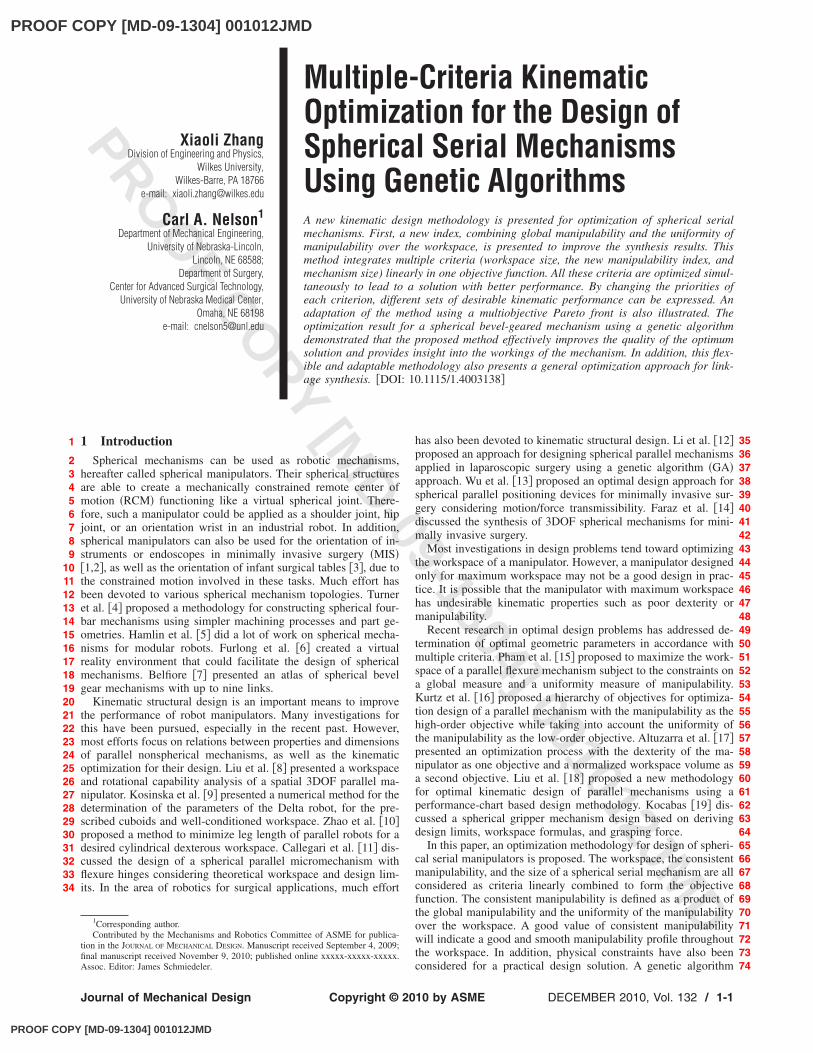
For a typical spherical serial mechanism, as shown in Fig. 1, allthe revolute joint axes intersect at one point �the rotation center orRCM�, leading to ai �i=1,2 , . . . ,n� being equal to zero. Thoughthe choice of origin location for each revolute joint is arbitrary,generally it is chosen at the intersecting point in order to cause dito be zero. All link angles ��1 ,�2 , . . . ,�n� are then the designparameters of a spherical serial mechanism of this type.
It is clear that the workspace of spherical manipulators is asector of a spherical surface; when radial motion is added, as withthe robot described in this paper, this becomes a sector of a spheri-cal shell. It is usually difficult to investigate the workspace ofspherical serial mechanisms, as the shape of the workspace can beirregular and discontinuous when the physical constraints are con-sidered. Research in this area has included workspace analysis ofspherical serial mechanisms through creation of atlases �21�.
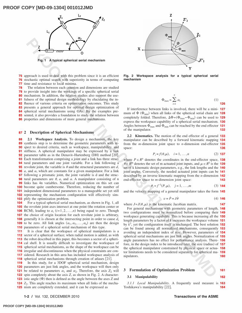
In this study, for a 3DOF spherical serial mechanism, designparameters are just link angles, and the workspace will then onlybe related to parameters �1 and �2. Therefore, the axis Z2 willspin completely about the axis Z, as shown in Fig. 2. A character-istic angle ��� then is defined as the angle between the axes Z andZ2. This angle reaches its maximum when all links of the mecha-nism are completely extended, and it can be expressed as
�max = �i=1
n
�i �1�
If interference between links is involved, there will be a mini-mum of � ��min� when all links of the spherical serial chain arecompletely folded. Therefore, ��= ��max−�min� can be used toexpress the workspace capability of a spherical serial mechanism.Angles between �max and �min can be reached by the end effectorof the manipulator.
2.2 Kinematics. The motion of the end effector of a generalmanipulator can be described by a forward kinematic mappingfrom the m-dimension joint space to n-dimension end-effectorspace:
Pi = f��,��, i = 1, . . . ,n �2�
where P�Rn denotes the coordinates in the end-effector space,��Rm denotes the set of m actuated joint inputs, and ��Rk is theset of k kinematic design parameters, e.g., the link lengths and thejoint angles. Conversely, the needed actuated joint inputs can bedescribed by an inverse kinematic mapping from the n-dimensionend-effector space to m-dimension joint space:
� j = f−1�P,��, j = 1, . . . ,m �3�and the velocity mapping of a general manipulator takes the form
v = P = J� �4�
where J=J�� ,�� is the kinematic Jacobian matrix.For general mechanisms with geometric parameters of length,
two configurations must be normalized before comparing theirworkspace generating capability. This is because increasing all thelength parameters by a factor of k increases the workspace volumeby k3, yet the configuration itself is unchanged. The best solutioncan be found among all normalized mechanisms, consequentlyavoiding an independent index of size. However, parameters ofspherical serial mechanisms are just link angles. Normalization ofangle parameters has no effect for performance analysis. There-fore, in the design index to be introduced later, the size �radius� ofthe spherical manipulator constrained by physical space or actua-tor limitations needs to be considered separately for spherical ma-nipulators.
3 Formulation of Optimization Problem
3.1 Manipulability
3.1.1 Local Manipulability. A frequently used measure isYoshikawa’s manipulability �22�,
Fig. 1 A typical spherical serial mechanism
Fig. 2 Workspace analysis for a typical spherical serialmechanism
757677787980818283848586
87
888990919293949596979899
100101102103104105106107108109110111112113114115116117118119120121122123124125
126
127128129130131132
133134135136
137
138139140141142143
144
145
146
147148149150151152153154155156157158159160
161
162
163164
1-2 / Vol. 132, DECEMBER 2010 Transactions of the ASME
PROOF COPY [MD-09-1304] 001012JMD
PROOF COPY [MD-09-1304] 001012JMD
PROO
F COPY [M
D-09-1304] 001012JMD
�l = �det�JJT� = ��1�2 ¯ �n �5�
The larger this measure, the closer the manipulator is to the iso-tropic configurations. Keeping �l far from 0 ensures good ma-nipulability. This measure is maximized by minimizing Dl definedfor each position:
Dl =1
1 + �lDl � �0,1� �6�
The advantage of Yoshikawa’s manipulability is that it can beexpressed analytically as a function of the link angle. As a mea-sure of manipulability, the determinant indicates both the absolutemanipulability value and singularities.
3.1.2 Global Conditioning Index. Kinematic indices are, ingeneral, dependent on the local position. To evaluate the globalproperties of the workspace, the global condition index �GCI�,which is the ratio between the integration of condition index andthe workspace volume, is defined �23�. It gives a measure in therange 0�Dg�1 that is independent of the size of the workspace.
Dg =
V
Dldv
V
dv
Dg � �0,1� �7�
The value of the above equation must be computed numericallyas these functions do not have analytic form. Most researchers justsample the workspace and average the discrete sum of the localmanipulability obtained at the sampled positions. Therefore,
Dg 1
N�i=1
N
Dli�8�
For the sum to approximate the integral, the sampled positionsshould be evenly distributed across the workspace with sufficientdensity.
3.1.3 Uniformity of Dexterity. Minimizing the global index Dgis not enough to ensure a good design, as an integral measurerepresents an average and does not take into account any poorlocal behavior exhibited by the manipulator. Therefore, it gives noindication of the uniformity of manipulability over the workspace.A design candidate with good manipulability could be poor over-all if there is any poor local behavior in its workspace. The uni-formity of manipulability over the workspace could indicate if thedesign has such poor local behaviors or not. The relative variationof these measures should be kept as small as possible to make thedexterous regions more consistent and useful.
Some effort has been devoted to uniformity measures of ma-nipulability. Kurtz et al. �16� employed the gradient measure ofthe local dexterity to formulate uniformity. By evaluating themaximal local uniformity over the workspace, the manipulabilitydistribution can be described. However, this method is computa-tionally expensive and is not able to reflect the global flatness ofmanipulability. In this study, a new method to evaluate the globaluniformity of manipulability is defined by calculating its standarddeviation. It is a global measure of flatness of the manipulability.
U =� 1
N�i=1
N � Dli− Dg
Dl max − Dl min�2
, U � �0,1� �9�
where Dl max is the maximum of the local manipulability over theworkspace, while Dl min is the minimal local manipulability. Thestandard deviation in Eq. �9� is normalized by �Dl max−Dl min�before comparing uniformity of different design candidates. Thesmaller the U is, the more uniform the manipulability is through-out the workspace. If U approaches 0, then the manipulability is
uniform throughout the workspace.The advantages of the use of the standard deviation to evaluate
the uniformity of manipulability include the relatively high com-putational efficiency and the global nature of evaluation of themanipulability throughout the workspace.
3.1.4 Consistent Manipulability. Taken alone, uniformity ofmanipulability throughout the workspace is not necessarily good,as the manipulability could be uniformly bad, throughout. Tosolve this problem, a function to combine uniformity and manipu-lability together is defined by multiplying the global manipulabil-ity with uniformity for each configuration. A good value of theirproduct will indicate high and uniform manipulability. In addition,as a single index, combination will significantly simplify the op-timization routine.
The consistent manipulability index in terms of standard devia-tion is defined as
UDg = 1 − �1 − Dg��1 − U�, UDg � �0,1� �10�
The goal is to minimize both Dg and U; therefore, the smaller thevalue of UDg, the better uniform manipulability one can get.
3.2 Workspace. As only related to link angles, the workspaceof a spherical serial mechanism could be evaluated by the anglebetween the axis Z of the base frame and the axis Zn of the endrevolute joint.
�� = �max − �min �11�The workspace is often desired to be maximized; however,
most practical designs are constrained by physical space or colli-sions, consequently limiting the useful portion of the workspace.Therefore, the workspace index can be expressed as
Ws = �c − ��
�cif �max �c
Ws � �0,1��min
�cif �max � �c
� �12�
where �c is the maximal angle allowed for physical space. Thesmaller Ws is, the larger the workspace the design candidate canprovide.
3.3 Size of Spherical Manipulators. Practically, sphericalmanipulators always have their physical limits, which will greatlyinfluence the size of the manipulator as well as the shape of theworkspace. As presented above in the description of sphericalmechanisms, the size of a spherical manipulator needs to be con-sidered separately, as the radius of a spherical manipulator has noinfluence on kinematic performance. Mathematically, the size of aspherical manipulator can be expressed as follows.
For cases with minimal physical constraints,
S =Rp − Rd
Rp, S � �0,1� �13�
where Rp is the physical radius of the spherical manipulator, andRd is the constraint of minimal radius. The smaller this measure,the smaller the size of the mechanism is. Rp should be larger thanRd in an optimization search in this case.
For cases with maximal physical constraints,
S =Rp
Rd, S � �0,1� �14�
where Rp is the physical radius of the spherical manipulator, andRd is the maximal constraint radius. The smaller this measure, thesmaller the size of the mechanism is. Rp should be smaller than Rdin an optimization search in this case.
For cases with both maximal and minimal physical constraints,
165
166167168169
170
171172173174
175176177178179180
181
182183184185
186
187188189
190191192193194195196197198199200201202203204205206207208209
210
211212213214215216
217218219220221
222223224225226227228229230231232
233
234235
236237238239
240
241242243244
245
246247248
249250251252253254255256257
258
259260261262263
264
265266267268269
Journal of Mechanical Design DECEMBER 2010, Vol. 132 / 1-3
PROOF COPY [MD-09-1304] 001012JMD
PROOF COPY [MD-09-1304] 001012JMD
PROO
F COPY [M
D-09-1304] 001012JMD
S =Rp − Rd min
Rd max − Rd min, S � �0,1� �15�
where Rd max and Rd min are the maximal and minimal constraintradius, respectively, and Rp is a value between them. The smallerthis measure, the smaller the size of the mechanism is.
3.4 Objective Function. All these criteria, including work-space �Ws�, consistent manipulability �UDg�, and size �S�, areminimized to achieve desirable performance. A positive objectivefunction F is designed to linearly combine these criteria and usedto evaluate candidate solutions. The complete resulting objectivefunction to evaluate the manipulator is
F = k1 � Ws + k2 � UDg + k3 � S �16�
where ki is the weight of ith criterion and k1+k2+k3=1. Bychanging the priorities �ki� of each criterion, various desirableperformances with different emphases can be achieved. The opti-mization goal is then to find a set of design parameters �DPs�,which minimizes the objective function �F� according to the pri-orities �ki�.
4 Genetic AlgorithmGA is an efficient stochastic optimal search method to solve
complex and nonlinear problems. The idea for this method origi-nated from natural evolution consisting of generation, selection,and mutation. It has the advantage of being resistant to localminima. In addition, a GA can also show superiority in terms ofcomputing time over random search methods. GA has been suc-cessfully applied to optimization problems such as scheduling,optimal control, transportation problems, and engineering design.This method is robust because it simultaneously evaluates manypoints in the search space and converges toward the global opti-mal solution.
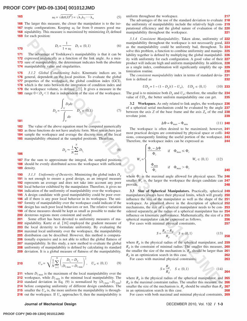
In general, an individual design candidate in a GA is repre-sented as a fixed-length string of genes; each gene is regarded ascarrying a genetic feature. An individual with better fitness is saidto have some genetic features that are capable of solving the prob-lem, and these features are expected to be propagated to the sub-sequent population by means of duplicating or recombining thegene sequence of parent populations. The operation of GA is aniteratively cyclic mechanism, as shown in Fig. 3.
A penalty function method is used to handle the constraints andto ensure that the fitness of any feasible solution is better thaninfeasible ones.
5 Kinematic Optimization of CoBRASurge
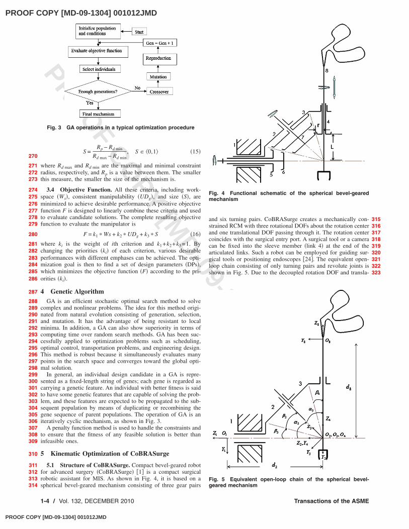
5.1 Structure of CoBRASurge. Compact bevel-geared robotfor advanced surgery �CoBRASurge� �1� is a compact surgicalrobotic assistant for MIS. As shown in Fig. 4, it is based on aspherical bevel-geared mechanism consisting of three gear pairs
and six turning pairs. CoBRASurge creates a mechanically con-strained RCM with three rotational DOFs about the rotation centerand one translational DOF passing through it. The rotation centercoincides with the surgical entry port. A surgical tool or a cameracan be fixed into the sleeve member �link 4� at the end of thearticulated links. Such a robot can be employed for guiding sur-gical tools or positioning endoscopes �24�. The equivalent open-loop chain consisting of only turning pairs and revolute joints isshown in Fig. 5. Due to the decoupled rotation DOF and transla-
Fig. 3 GA operations in a typical optimization procedure
Fig. 4 Functional schematic of the spherical bevel-gearedmechanism
Fig. 5 Equivalent open-loop chain of the spherical bevel-geared mechanism
270
271272273
274275276277278279
280
281282283284285286
287
288289290291292293294295296297298299300301302303304305306307308309
310
311312313314
315316317318319320321322323
1-4 / Vol. 132, DECEMBER 2010 Transactions of the ASME
PROOF COPY [MD-09-1304] 001012JMD
PROOF COPY [MD-09-1304] 001012JMD
PROO
F COPY [M
D-09-1304] 001012JMD
tion DOF, the rotation capability of CoBRASurge can be opti-mized independently.
5.2 Expected Performance Requirements of CoBRASurge.As a surgical robotic assistant for MIS, CoBRASurge shouldcover the dexterous workspace �DWS� �2�, which contains 95% ofsurgical tool motion. The DWS for MIS is defined as a conehaving a vertex angle of 60 deg with its tip located at the incisionport. Also, the end effector should be orientated smoothly anddexterously for safety issues. Size is another concern as a cum-bersome robot will cause unwanted interactions with other equip-ment or personnel in the operating room and also has a negativeeffect on robot dynamics and control. With these points in mind,the design goal is to find the optimal dimensions for a compactspherical bevel-geared manipulator, to obtain maximal workspaceincluding the necessary DWS with maximal consistentmanipulability.
Physical constraints are not negligible due to its particular ap-
plication in surgical procedures. First, the maximal workspaceconstraint �c of 90 deg is required for link angles to provide alarger, open center space and avoid patient-robot collisions. Sec-ond, due to the unique method of surgical tool mounting, theinside diameter of link 4 should be larger than the diameter ofsurgical tools. In addition, the distance between the bottom sur-face of link 4 and the rotation center should be large enough to becompatible with existing trocars �incision port stabilizationsleeves�. Therefore, this optimization has a minimal physical con-straint for radius Rd. Finally, pitch angles for each bevel gearshould be larger than 5 deg for a practical, stiff design solution.
5.3 Jacobian. Equation �17� is a general recursive expressionof the velocity of the end effector. Following this equation, thevelocity of the Z4 axis �the unit longitudinal axis of the end effec-tor� is first expressed in frame 4, as shown in Eq. �18�.
i+1vi+1 = ii+1R�ivi + iwi � iPi+1� �17�
4v4 = �24R�0
0
1��21 + 3
4R�0
0
1��32� � 4Z4 = � c�43c�32c�3s�2 + c�43c�2s�3 − s�43s�32s�2 c�43s�3 0
− s�43c�32c�3s�2 − s�43c�2s�3 − c�43s�32s�2 − s�43s�3 0
0 0 0���21
�32
�43
� �18�
where �21, �32, and �43 are the joint angles. �21, �32, and �43 are the joint velocities. 24R is the transformation matrix from frame 2 to
frame 4 and 34R is the transformation matrix from frame 3 to frame 4.
Equation �18� can be rewritten in terms of frame 1 as
1v4 = �41vx
41vy
41vz
� = �− s�21s�32s�3 + c�21c�32c�2s�3 + c�21c�3s�2 c�21c�32s�3 − s�21s�32c�2s�3 0
c�21s�32s�3 + s�21c�32c�2s�3 + s�21c�3s�2 s�21c�32s�3 + c�21s�32c�2s�3 0
0 s�32s�3s�2 0���21
�32
�43
� �19�
Equation �19� reveals that the longitudinal axis of the end effector only relates to the two controlled joint velocities, �21 and �32. This
further validates the transformation matrix, as �43 only affects the self-rotation degree of freedom about the longitudinal axis of the endeffector and will not affect the orientation of the longitudinal axis of the end effector. Thus, the left 3�2 submatrix of the full 3�3Jacobian is taken to yield a 3�2 version mapping the joint velocities to the end-effector velocity.
1v4 = �41vx
41vy
41vz
� = 1J3�2��21
�32
� �20�
1J = �− s�21s�32s�3 + c�21c�32c�2s�3 + c�21c�3s�2 c�21c�32s�3 − s�21s�32c�2s�3
c�21s�32s�3 + s�21c�32c�2s�3 + s�21c�3s�2 s�21c�32s�3 + c�21s�32c�2s�3
0 s�32s�3s�2� �21�
By substituting the relations between actuated input angles andjoint angles in Ref. �1�, the Jacobian matrix of the mechanism canbe written as
1v4 = �41vx
41vy
41vz
� = 1J3�2��21
�32
� = 1J3�2� � ��21
�51
�1J3�2� = 1J3�2 � � 1 0
− N53 N53� �22�
where �21 and �51 are the actuated input angular velocities for gear2 and gear 5, respectively. N53 is the gear ratio as determined bynumbers of teeth.
This version of the Jacobian is used here for calculating ma-nipulability. Also, it illustrates that Yoshikawa’s manipulability
has advantages over other dexterity evaluation methods for spheri-cal serial mechanisms as it avoids the need to find eigenvalues fornonsquare Jacobian matrices.
5.4 Workspace Analysis. A general workspace of the spheri-cal bevel-geared mechanism is just like the one shown in Fig. 2,where � is defined as the angle between the Z axis of the fixedframe and the Z4 axis of the end effector. Benefiting from itsstructural properties, the �max and �min can be directly deter-mined by workspace investigation. It was found that the threeimportant factors are three pitch angles, 3, 4, and 5 �shown inFig. 5�, which, in fact, specify the link angles ��2 by �2= 3+ 5
and �3 by �3= 3+ 4�. The singularities are �max=�2+�3=2 3
+ 4+ 5. �min can be expressed by 4+ 5. Therefore, the work-space range of a spherical bevel-geared mechanism of this typecan be expressed as
324325
326327328329330331332333334335336337338339340
357358
359
360361362
363
364
365366367
368
369
370371372
373374375
376
377
378379380381382
341342343344345346347348349350351
352353354355
356
383384385
386387388389390391392393394395396397
Journal of Mechanical Design DECEMBER 2010, Vol. 132 / 1-5
PROOF COPY [MD-09-1304] 001012JMD

PROOF COPY [MD-09-1304] 001012JMD
PROO
F COPY [M
D-09-1304] 001012JMD
�� = �max − �min = 2 3 �23�
Obviously, �� can be treated as the maximal vertex angle of acone that a particular spherical bevel-geared mechanism contains.Consequently, maximizing the vertex angle of a cone in this de-sign problem is equivalent to maximizing ��.
Due to the aforementioned tool mounting method constraints�the end effector or tool is inserted into link 4, and the spacebetween link 4 and the rotation center should contain a trocar�, theinside diameter of link 4 has to be larger than the diameter of theend effector, typically 10 mm, and the distance L has to be largerthan 65 mm for compatibility with existing trocars. Assume thatthe pitch radius of link 4 �r� is the same as its inner diameter toguarantee physical strength of gears; the relation between 4 and�r ,L� can be then expressed as tan� 4�=r /L, as shown in Fig. 5.Therefore, r and L not only affect 4 and �min but also the radius�physical size� of the spherical gear train. To involve these physi-cal constraints in the optimization routine, 4 is replaced by thisfunction of r and L, and consequently the geometric parametersfor optimal design of CoBRASurge become 3, 5, r, and L.
5.5 Optimization Parameters. The parameters used in thiswork are shown in Table 1. These parameters have been set ac-cording to previous research in the evolutionary algorithms field�25,26� and have been verified to be the most efficient to imple-ment for the genetic algorithm. They have been tested on thecurrent simulation and seem reasonable considering the optimiza-tion results.
The bounding intervals for design variables are shown in Table2. These bounding intervals are chosen based on the preliminarystudy of the relation between the design parameters and the cre-ated workspace and also based on the size constraint of designspecifications as a surgical robot including interlink collisionavoidance �1�. There are various priority level sets for each crite-rion due to different kinematic performance emphases. One ofthese sets is shown in Table 3 with more concern formanipulability.
The workspace between �max and �min for each design candi-date was discretized evenly at 2 deg increments in azimuth andelevation.
6 Optimization ResultsComplete optimization allows finding the best individual ac-
cording to the objective function. This procedure was imple-mented using the genetic algorithm and direct search toolbox inMATLAB.
The algorithm can be considered reliable, as each simulationproduces a similar profile of evolution. Figure 6 shows a typicalevolution of the adaptation of the fitness of the robot. The algo-rithm shows good convergence. After 400 generations, the bestindividual fitness stays close to 0.266 and the average close to0.290. It can be seen that the algorithm improves very fast in thebeginning, while it converges much more slowly as it approachesthe optimum.
Using the GA, optimal design parameters and the correspond-ing optimum objective function value can be obtained, as shownin Table 4. The value of r is very close to the minimal pitch radiuslimit of 10 mm. With L=83.2 mm, the pitch angle 4 isarctan�r /L�=7.3 deg. The value of 5 is very close to the mini-mal pitch angle limit of 5 deg, which suggests that both 4 and 5degenerate to reduce �min subject to satisfying the physical con-straints. This optimization result presents a design configuration of�max=88.5 deg, �min=12.5 deg, and ��=76 deg, which reallyreflects the requirement of workspace maximization.
7 Relations of Dimensions and CriteriaAs 4 and 5 are symmetrical in structure and have similar
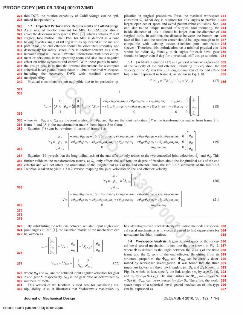
effect on kinematic performance, the following discussion focuseson investigating relations between properties and dimensions ofCoBRASurge using all the combinations of 3 and 5. Figure 7shows the distribution of Yoshikawa’s manipulability index at� 3 , 5 ,r ,L�= � 3 , 5 ,10.7,83.2�. For the spherical serial manipu-lator, optimizing the manipulability, the best design was achievedwith 3=65 deg and 5=10 deg, as shown in Fig. 7. In contrast,optimizing the uniformity, the best design was achieved with 3=5 deg and 5=7.5 deg, as shown in Fig. 8. When optimizingthe product combination of manipulability and its uniformity, the
Table 1 Parameters used for the genetic algorithm
Population size Npop 20Maximal generation number Gmax 400No. of variables Nvar 4Reproduction elite count Nrep 2Crossover fraction F1 0.8Mutation rate F2 0.02
Table 2 Bounding interval for design variables
3�deg�
5�deg�
r�mm�
L�mm�
Min 5 5 10 65Max 65 40 N/A N/A
Table 3 Weight of each criterion
Criterion Weights, ki
Workspace Ws k1=0.2Consistent manipulability UDg k2=0.6Size S k3=0.2
Fig. 6 Fitness convergence of a typical GA evolution
Table 4 Optimization result for CoBRASurge „k1=0.2, k2=0.6,and k3=0.2….
3�deg�
5�deg�
r�mm�
L�mm�
Value 38.0 5.2 10.7 83.2
398
399400401402403404405406407408409410411412413414415416
417418419420421422423424425426427428429430431432433434435
436
437438439440441442443444445446447448449450451452453454455456457458
459
460461462463464465466467468469470
1-6 / Vol. 132, DECEMBER 2010 Transactions of the ASME
PROOF COPY [MD-09-1304] 001012JMD
PROOF COPY [MD-09-1304] 001012JMD
PROO
F COPY [M
D-09-1304] 001012JMD
best design was achieved with 3=65 deg and 5=19.5 deg�shown in Fig. 9�. These results are summarized in Table 5.
The differences between the results for the three distinct casespresented in Table 5 are to be expected. If one chooses the designthat optimizes the uniformity of manipulability, the resulting de-sign should be more likely to reach only a narrow range of posi-
tions, with 3 tending toward zero. In fact, the resulting design inthis position is in singularity with all links fully extended and theworst manipulability happens here. Therefore, the uniformity andthe global manipulability have opposite trends. The resulting so-lution in terms of consistent manipulability will be a compromiseof the manipulability optimization and uniformity optimization. Inthis particular case, the manipulability dominated the optimizationof the consistent manipulability. However, this dominance is notalways absolute, and it is dependent on the magnitude of eachindex. Although the inclusion of uniformity of manipulability inthe consistent manipulability index seems to not significantly af-fect the result in optimizing the manipulability given the similaritybetween the first and third rows of Table 5, the following ex-amples with multiple criteria will illustrate that it does effectivelyimprove the kinematic performance of the design result.
Figure 10 shows the workspace generated by the resulting ma-nipulator at � 3 , 5 ,r ,L�= � 3 , 5 ,10.7,83.2�. The larger thevalue of 5, the larger the value of �min, leading to a poor work-space. In contrast, increasing the value of 3 will effectively in-crease the value of �max, leading to a good workspace capability.The transition of this trend happens when �max exceeds 90 deg. Inthose cases, the useful workspace is only inversely proportional to 5 and no longer related to 3. The radius �physical size� of Co-BRASurge is only dependent on r and L and is not plotted heresince it is rather straightforward.
The fitness surfaces at � 3 , 5 ,r ,L�= � 3 , 5 ,10.7,83.2� areshown in Figs. 11 and 12. The only difference is that Fig. 11employed the consistent manipulability in the objective function,while Fig. 12 used Yoshikawa’s manipulability index. Using thesame scale of fitness value, the fitness surface with consistentmanipulability has lower magnitudes and slopes more gently thanthat generated using the traditional approach. The optimizationresults are listed in Table 6. With the fixed values of r and L, theoptimum result using consistent manipulability is achieved with 3=38 deg and 5=5.2 deg, while the optimum result using ma-nipulability is achieved with 3=59.5 deg and 5=5 deg. Thedifference in the results is also expected as the former involving
Fig. 7 Yoshikawa’s manipulability of CoBRASurge
Fig. 8 Standard deviation of Yoshikawa’s manipulability
Fig. 9 Consistent manipulability of CoBRASurge
Table 5 Optimized results using different indices
Measure of manipulability �k1=0 , k2=1 , k3=0� 3
�deg� 5
�deg�
Yoshikawa’s manipulability 65 10Uniformity 5 7.5Consistent manipulability 65 19.5
Fig. 10 Workspace of CoBRASurge
471472473474475476
477478479480481482483484485486487488489490491492493494495496497498499500501502503504505506507508509510511512513
Journal of Mechanical Design DECEMBER 2010, Vol. 132 / 1-7
PROOF COPY [MD-09-1304] 001012JMD

PROOF COPY [MD-09-1304] 001012JMD
PROO
F COPY [M
D-09-1304] 001012JMD
consistent manipulability leads to a more realistically useful de-sign �it has essentially the same usable workspace, has physicallysmaller components, and has more uniform kinematic perfor-mance across its workspace�.
The property surface and results here are all based on the givenweights for each criterion of the objective function, where k1=0.2, k2=0.6, and k3=0.2. Changing the values of ki will expressdifferent sets of desirable kinematic performance, which will leadto different optimum results even using the same optimizationroutine. The influence of a single criterion on the design param-eters is obvious by setting k1=1, k2=1, or k3=1, respectively. Asshown in Table 7, the optimization emphasizing workspace capa-bility �row 1� causes a decrease of 5 and r, and an increase of 3and L. Such a set of design parameters can achieve a desiredworkspace capability �� as well as a small �min. The effect ofemphasizing consistent manipulability �row 8� leads to the in-
crease of 3, 5, and r, whereas emphasizing compact mechanismsize �row 10� induces a minimum 3 and L. For multicriteriaoptimization, some objectives work together constructively ratherthan being in conflict. For example, both workspace capabilityand consistent manipulability result in an increased 3 �rows 3and 5�. However, more often, different criteria lead to oppositetrends in the design parameters. For example, a good workspacecapability requires that 3 and L increase, while a compactmechanism size induces a minimum 3 and L �rows 2 and 4�. Thisconflict also exists in 5 and r subject to the criteria combinationof a good workspace and a good consistent manipulability �row3�. As a result, the outcome is a trade-off of the criteria, and theone with highest preference will tend to dominate the optimizationoutcome. The designer can measure the overall performance ofthe design candidates based on a composite of the preferences ofthese goals.
8 Observations Using Pareto GraphsThe multiobjective optimization problem is also solved by
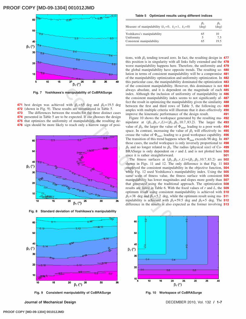
means of Pareto efficiency �27�. The three criteria are set as threeindividual objective functions to be optimized. The lower and up-per bounds of the design variables are the same as in Table 2. Amultiobjective genetic algorithm �MOGA� in MATLAB was used toobtain the Pareto frontier based on the size, the workspace, andthe consistent manipulability. The MOGA parameters are given inTable 8. Compared with the regular GA, the MOGA uses Paretoefficiency to process and analyze the individuals of each popula-tion in the current generation. It then returns the output variableson the Pareto frontier for the feasible solutions in the next genera-tion. At the end, the Pareto-optimal solutions are obtained fromthe generated feasible solutions.
The Pareto frontier for optimization of CoBRASurge param-eters is shown in Fig. 13. The Pareto frontiers for the bi-objectiveoptimization GA are shown in Fig. 14–16. All the points on thisPareto frontier are feasible solutions and the designers can find afair compromise solution on this surface respecting all three ob-jectives. Also, a set of weight coefficients can be assigned to thegenerated feasible solutions. Using the linear combination of Eq.�16�, the optimal solution associated with the particular weightcoefficients can be found on the Pareto frontier. Some optimaldesign solutions based on three different sets of weight coeffi-
Fig. 11 Fitness value of CoBRASurge using consistent ma-nipulability index
Fig. 12 Fitness value of CoBRASurge using Yoshikawa’s ma-nipulability index
Table 6 Optimization results using different manipulabilityindices
I �k1=0.2, k2=0.6, k3=0.2� 3
�deg� 5
�deg�r
�mm�L
�mm�
Consistent manipulability 38.0 5.2 10.7 83.2Yoshikawa’s manipulability 59.5 5 10.7 83.2
Table 7 Optimization results using different criteria weights, ki
Criteria weights Optimum results
k1 k2 k3
3�deg�
5�deg�
r�mm�
L�mm�
1 1 0 0 42 5.1 10.1 570.12 0.6 0.2 0.2 38.2 6.1 10.1 783 0.5 0.5 0 41.2 5.1 20.1 517.34 0.5 0 0.5 37.3 6.4 10.2 655 0.33 0.33 0.33 40.2 6.5 10.1 656 0.2 0.6 0.2 38 5.2 10.7 83.27 0.2 0.2 0.6 35.8 8.8 10.1 658 0 1 0 64.6 22.4 160.3 116.89 0 0.5 0.5 5.1 37.4 10 65.1
10 0 0 1 5.1 34.7 10.2 65.1
Table 8 Parameters used for the MOGA
Population size Npop 100Maximal generation number Gmax 800Number of variables Nvar 4Crossover fraction F1 0.8Mutation rate F2 0.02
514515516517518519520521522523524525526527528529
530531532533534535536537538539540541542543544545
546
547548549550551552553554555556557558559560561562563564565566567568569
1-8 / Vol. 132, DECEMBER 2010 Transactions of the ASME
PROOF COPY [MD-09-1304] 001012JMD
PROOF COPY [MD-09-1304] 001012JMD
PROO
F COPY [M
D-09-1304] 001012JMD
cients are outlined in Table 9. They are highly consistent with theresults obtained using the proposed optimization method in Sec. 7.
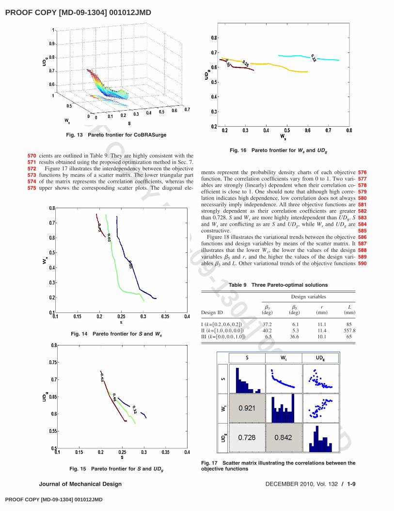
Figure 17 illustrates the interdependency between the objectivefunctions by means of a scatter matrix. The lower triangular partof the matrix represents the correlation coefficients, whereas theupper shows the corresponding scatter plots. The diagonal ele-
ments represent the probability density charts of each objectivefunction. The correlation coefficients vary from 0 to 1. Two vari-ables are strongly �linearly� dependent when their correlation co-efficient is close to 1. One should note that although high corre-lation indicates high dependence, low correlation does not alwaysnecessarily imply independence. All three objective functions arestrongly dependent as their correlation coefficients are greaterthan 0.728. S and Ws are more highly interdependent than UDg. Sand Ws are conflicting as are S and UDg, while Ws and UDg areconstructive.
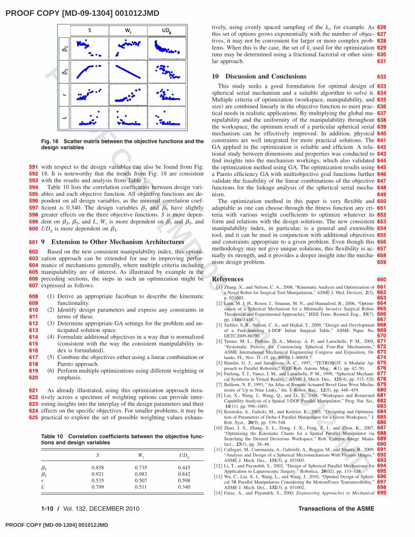
Figure 18 illustrates the variational trends between the objectivefunctions and design variables by means of the scatter matrix. Itillustrates that the lower Ws, the lower the values of the designvariables 5 and r, and the higher the values of the design vari-ables 3 and L. Other variational trends of the objective functions
Fig. 13 Pareto frontier for CoBRASurge
Fig. 14 Pareto frontier for S and Ws
Fig. 15 Pareto frontier for S and UDg
Fig. 16 Pareto frontier for Ws and UDg
Table 9 Three Pareto-optimal solutions
Design ID
Design variables
3�deg�
5�deg�
r�mm�
L�mm�
I �k= �0.2,0.6,0.2�� 37.2 6.1 11.1 85II �k= �1.0,0.0,0.0�� 40.2 5.3 11.4 557.8III �k= �0.0,0.0,1.0�� 6.5 36.6 10.1 65
Fig. 17 Scatter matrix illustrating the correlations between theobjective functions
570571572573574575
576577578579580581582583584585586587588589590
Journal of Mechanical Design DECEMBER 2010, Vol. 132 / 1-9
PROOF COPY [MD-09-1304] 001012JMD
PROOF COPY [MD-09-1304] 001012JMD
PROO
F COPY [M
D-09-1304] 001012JMD
with respect to the design variables can also be found from Fig.18. It is noteworthy that the trends from Fig. 18 are consistentwith the results and analysis from Table 7.
Table 10 lists the correlation coefficients between design vari-ables and each objective function. All objective functions are de-pendent on all design variables, as the minimal correlation coef-ficient is 0.340. The design variables 3 and 5 have slightlygreater effects on the three objective functions. S is more depen-dent on 3, 5, and L, Ws is more dependent on 3 and 5, andUDg is more dependent on 3.
9 Extension to Other Mechanism ArchitecturesBased on the new consistent manipulability index, this optimi-
zation approach can be extended for use in improving perfor-mance of mechanisms generally, where multiple criteria includingmanipulability are of interest. As illustrated by example in thepreceding sections, the steps in such an optimization might beexpressed as follows:
�1� Derive an appropriate Jacobian to describe the kinematicfunctionality.
�2� Identify design parameters and express any constraints interms of these.
�3� Determine appropriate GA settings for the problem and an-ticipated solution space.
�4� Formulate additional objectives in a way that is normalized�consistent with the way the consistent manipulability in-dex is formulated�.
�5� Combine the objectives either using a linear combination orPareto approach.
�6� Perform multiple optimizations using different weighting oremphasis.
As already illustrated, using this optimization approach itera-tively across a spectrum of weighting options can provide inter-esting insights into the interplay of the design parameters and theireffects on the specific objectives. For smaller problems, it may bepractical to explore the set of possible weighting values exhaus-
tively, using evenly spaced sampling of the ki, for example. Asthis set of options grows exponentially with the number of objec-tives, it may not be convenient for larger or more complex prob-lems. When this is the case, the set of ki used for the optimizationruns may be determined using a fractional factorial or other simi-lar approach.
10 Discussion and ConclusionsThis study seeks a good formulation for optimal design of
spherical serial mechanism and a suitable algorithm to solve it.Multiple criteria of optimization �workspace, manipulability, andsize� are combined linearly in the objective function to meet prac-tical needs in realistic applications. By multiplying the global ma-nipulability and the uniformity of the manipulability throughoutthe workspace, the optimum result of a particular spherical serialmechanism can be effectively improved. In addition, physicalconstraints are well integrated for more practical solutions. TheGA applied in the optimization is reliable and efficient. A rela-tional study between dimensions and properties was conducted tofind insights into the mechanism workings, which also validatedthe optimization method using GA. The optimization results usinga Pareto efficiency GA with multiobjective goal functions furthervalidate the feasibility of the linear combinations of the objectivefunctions for the linkage analysis of the spherical serial mecha-nism.
The optimization method in this paper is very flexible andadaptable as one can choose through the fitness function any cri-teria with various weight coefficients to optimize whatever itsform and relations with the design solutions. The new consistentmanipulability index, in particular, is a general and extensibletool, and it can be used in conjunction with additional objectivesand constraints appropriate to a given problem. Even though thismethodology may not give unique solutions, this flexibility is ac-tually its strength, and it provides a deeper insight into the mecha-nism design problem.
References�1� Zhang, X., and Nelson, C. A., 2008, “Kinematic Analysis and Optimization of
a Novel Robot for Surgical Tool Manipulation,” ASME J. Med. Devices, 2�2�,p. 021003.
�2� Lum, M. J. H., Rosen, J., Sinanan, M. N., and Hannaford, B., 2006, “Optimi-zation of a Spherical Mechanism for a Minimally Invasive Surgical Robot:Theoretical and Experimental Approaches,” IEEE Trans. Biomed. Eng., 53�7�,pp. 1440–1445.
�3� Siebler, S. R., Nelson, C. A., and Hejkal, T., 2009, “Design and Developmentof a Free-Standing 4-DOF Infant Surgical Table,” ASME Paper No.DETC2009-86790.
�4� Turner, M. L., Perkins, D. A., Murray, A. P., and Larochelle, P. M., 2005,“Systematic Process for Constructing Spherical Four-Bar Mechanisms,”ASME International Mechanical Engineering Congress and Exposition, Or-lando, FL, Nov. 11–15, pp. 80058.1–80058.7.
�5� Hamlin, G. J., and Sanderson, A. C., 1997, “TETROBOT: A Modular Ap-proach to Parallel Robotics,” IEEE Rob. Autom. Mag., 4�1�, pp. 42–50.
�6� Furlong, T. J., Vance, J. M., and Larochelle, P. M., 1999, “Spherical Mechani-cal Synthesis in Virtual Reality,” ASME J. Mech. Des., 121�4�, pp. 515–520.
�7� Belfiore, N. P., 1993, “An Atlas of Remote Actuated Bevel Gear Wrist Mecha-nisms of Up to Nine Links,” Int. J. Robot. Res., 12�5�, pp. 448–459.
�8� Liu, X., Wang, J., Wang, Q., and Li, T., 2004, “Workspace and RotationalCapability Analysis of a Spatial 3-DOF Parallel Manipulator,” Prog. Nat. Sci.,14�11�, pp. 996–1003.
�9� Kosinska, A., Galicki, M., and Kedzior, K., 2003, “Designing and Optimiza-tion of Parameters of Delta-4 Parallel Manipulator for a Given Workspace,” J.Rob. Syst., 20�9�, pp. 539–548.
�10� Zhao, J. S., Zhang, S. L., Dong, J. X., Feng, Z. J., and Zhou, K., 2007,“Optimizing the Kinematic Chains for a Spatial Parallel Manipulator viaSearching the Desired Dexterous Workspace,” Rob. Comput.-Integr. Manu-fact., 23�1�, pp. 38–46.
�11� Callegari, M., Cammarata, A., Gabrielli, A., Ruggiu, M., and Sinatra, R., 2009,“Analysis and Design of a Spherical Micromechanism With Flexure Hinges,”ASME J. Mech. Des., 131�5�, p. 051003.
�12� Li, T., and Payandeh, S., 2002, “Design of Spherical Parallel Mechanisms forApplication to Laparoscopic Surgery,” Robotica, 20�02�, pp. 133–138.
�13� Wu, C., Liu, X. J., Wang, L., and Wang, J., 2010, “Optimal Design of Spheri-cal 5R Parallel Manipulators Considering the Motion/Force Transmissibility,”ASME J. Mech. Des., 132�3�, p. 031002.
�14� Faraz, A., and Payandeh, S., 2000, Engineering Approaches to Mechanical
Fig. 18 Scatter matrix between the objective functions and thedesign variables
Table 10 Correlation coefficients between the objective func-tions and design variables
S Ws UDg
5 0.858 0.735 0.445 3 0.921 0.983 0.842r 0.535 0.507 0.598L 0.799 0.511 0.340
591592593594595596597598599600
601
602603604605606607
608609610611612613614615616617618619620
621622623624625
626627628629630631
632
633634635636637638639640641642643644645646647648649650651652653654655656657658659
660661662663664665666667668669670671672673674675676677678679680681682683684685686687688689690691692693694695696697698699
1-10 / Vol. 132, DECEMBER 2010 Transactions of the ASME
PROOF COPY [MD-09-1304] 001012JMD

PROOF COPY [MD-09-1304] 001012JMD
PROO
F COPY [M
D-09-1304] 001012JMD
and Robotic Design for Minimally Invasive Surgeries, Kluwer Academic, Nor-well, MA.
�15� Pham, H. H., and Chen, I. M., 2003, “Optimal Synthesis for Workspace andManipulability of Parallel Flexure Mechanism,” 11th World Congress inMechanism and Machine Science, Tianjin, China, Aug. 18–21, Vol. 4, pp.2069–2073.
�16� Kurtz, R., and Hayward, V., 1992, “Multiple-Goal Kinematic Optimization ofa Parallel Spherical Mechanism With Actuator Redundancy,” IEEE Trans.Rob. Autom., 8�5�, pp. 644–651.
�17� Altuzarra, O., Hernandez, A., Salgado, O., and Angeles, J., 2009, “Multiob-jective Optimum Design of a Symmetric Parallel Schönflies-Motion Genera-tor,” ASME J. Mech. Des., 131�3�, pp. 031002.
�18� Liu, X., and Wang, J., 2007, “A New Methodology for Optimal KinematicDesign of Parallel Mechanisms,” Mech. Mach. Theory, 42�9�, pp. 1210–1224.
�19� Kocabas, H., 2009, “Gripper Design With Spherical Parallelogram Mecha-nism,” ASME J. Mech. Des., 131�7�, p. 075001.
�20� Craig, J. J., 2004, Introduction to Robotics Mechanics & Control, StanfordUniversity Press, Stanford, CA.
�21� Liu, X., Wang, J., and Gao, F., 2003, “Workspace Atlases for the Design ofSpherical 3-DOF Serial Wrists,” J. Intell. Robotic Syst., 36�4�, pp. 389–405.
�22� Yoshikawa, T., 1985, “Manipulability of Robotic Mechanism,” Int. J. Robot.Res., 4�2�, pp. 3–9.
�23� Asada, H., and Cro Crantio, J. A., 1985, “Kinematic and Static Characteriza-tion of Wrist Joints and Their Optimal Design,” Proceedings of the IEEEInternational Conference on Robotics and Automation, St. Louis, MO, pp.244–250.
�24� Zhang, X., Oleynikov, D., and Nelson, C. A., 2009, “Portable Tool PositioningRobot for Telesurgery,” Stud. Health Technol. Inform., 142, pp. 438–443.
�25� DeJong, K. A., 1975, An Analysis of the Behavior of a Class of GeneticAdaptive Systems, Ph.D. thesis, University of Michigan, Ann Arbor MI.
�26� Grefenstette, J. J., 1986, “Optimization of Control Parameters for GeneticAlgorithms,” IEEE Trans. Syst. Man Cybern., 16�1�, pp. 122–128.
�27� Konak, A., Coit, D. W., and Smith, A. E., 2006, “Multi-Objective Optimiza-tion Using Genetic Algorithms: A Tutorial,” Reliab. Eng. Syst. Safety, 91�9�,pp. 992–1007.
700701702703704705706707708709710711712713714715716717
718719720721722723724725726727728729730731732733734
Journal of Mechanical Design DECEMBER 2010, Vol. 132 / 1-11
PROOF COPY [MD-09-1304] 001012JMD