multipath propagation characterization...
TRANSCRIPT

Helsinki University of Technology Radio Laboratory Publications
Teknillisen korkeakoulun Radiolaboratorion julkaisuja
Espoo, October, 2002 REPORT S 256
MULTIPATH PROPAGATION CHARACTERIZATION FOR
TERRESTRIAL MOBILE AND FIXED MICROWAVE
COMMUNICATIONS
Thesis for the degree of Doctor of Science in Technology
Xiongwen Zhao

Helsinki University of Technology Radio Laboratory Publications
Teknillisen korkeakoulun Radiolaboratorion julkaisuja
Espoo, October, 2002 REPORT S 256
MULTIPATH PROPAGATION CHARACTERIZATION FOR
TERRESTRIAL MOBILE AND FIXED MICROWAVE
COMMUNICATIONS
Xiongwen Zhao
Dissertation for the degree of Doctor of Science in Technology to be presented with due
permission for public examination and debate in Auditorium S4 at Helsinki University of
Technology (Espoo, Finland) on the 13th of December 2002 at 12 o’clock noon.
Helsinki University of Technology
Department of Electrical and Communications Engineering
Radio Laboratory
Teknillinen korkeakoulu
Sähkö- ja tietoliikennetekniikan osasto
Radiolaboratorio

Distribution:
Helsinki University of Technology
Radio Laboratory
P.O.Box 3000
FIN-02015 HUT
Tel. +358-9-451 2252
Fax. +358-9-451 2152
© Xiongwen Zhao and Helsinki University of Technology Radio Laboratory
ISBN 951-22- 6164-2
ISSN 1456-3835
Otamedia Oy
Espoo 2002

3
PREFACE This thesis has been carried out at the Radio Laboratory of Institute of Digital Communications in Helsinki University of Technology during October 1998 – May 2002. During this period, I mainly worked for LALAMO (Wireless Wideband Modems) project funded by TEKES, coordinated by VTT Electronics and supported by Elektrobit Oyj, Nokia Networks and Elisa Communications. Some parts of the work had been done when I worked in China Research Institute of Radiowave Propagation (CRIRP). I thank the LALAMO project for funding my research work, which made this thesis possible. First and foremost I would like to thank my supervisor, Prof. Pertti Vainikainen, for his very helpful guidance, the numerous novel ideas and encouragement during all my work. I would like to thank Prof. Antti Räisänen very much for his encouragement and support. I thank Dr. Jarmo Kivinen for fruitful discussions in many aspects and very good cooperation in the project work, Dr. Ioannis T. Rekanos for helpful discussions, and Stina Lindberg for her excellent work and kindness. I thank my thesis pre-examiners Prof. Andreas F. Molisch and Dr. Wei Zhang for their helpful comments and suggestions. Last but not least I would like to thank my wife Suiyan Geng and my daughter Gengjing Zhao for their love, patience and understanding, and my parents for their endless encouragement. Helsinki, October, 2002. Xiongwen Zhao
4
ABSTRACT Multipath propagation is a key issue studied throughout this thesis, and it causes dispersions in delay, frequency and spatial domains. These are dominant phenomena in both terrestrial mobile and fixed wideband communications. In this thesis, multipath propagation mechanisms including diffraction, refraction, reflection and scattering are studied when radio waves interact with dielectric and metallic objects, or an atmospheric duct. Measurements were also performed for empirical modelling and validation of the theoretical work carried out in this thesis. By using physical optics (PO) method, the attenuation by double knife edges with ground reflections is solved for the first time under a general formula of the attenuation by multiple knife edges with ground reflections derived in this thesis, and some important and interesting conclusions are obtained. The attenuations by curvilinear-topped obstacles and by multiple flat-topped obstacles are also presented in closed forms. The results are the simplest and easiest ones available now, and they can be applied for field strength predictions both in mobile and fixed microwave communications. Based on three-ray (direct, reflected and super-refracted) and two-ray (direct and super-refracted) multipath models for plane and spherical earth, respectively, frequency selective fading (FSF) and depolarization due to clear air are studied by simulations and experiments for terrestrial line-of-sight (LOS) microwave links and dual-polarized communication systems. Novel simulation methods have been introduced and applied based on the fact that the amplitudes and excess delays of the rays are functions of the (modified) refractive index gradients which are random variables with exponential and normal distributions inside and outside the duct in lower atmosphere, respectively. Some important empirical or semi-empirical models and parameters are presented at 5 GHz based on large amount of measured data in indoor and outdoor environments. The results include path loss models, excess delay and rms delay spread, spatial and frequency correlations, window (sector) length of averaging fast fading components, path number distribution, and tapped-delay-line (TDL) channel models. These empirical or semi-empirical parameters and models are the latest results achieved at 5 GHz, and they are of great importance in designing of future wireless local area networks (WLAN), especially the TDL models are developed for the first time in this frequency band. Using a general autocorrelation function derived in this thesis for three- dimensional (3-D) scattering environments, a novel theoretical modelling method is developed to study the propagation mechanisms of different types of Doppler spectra observed in measurements. The 3-D autocorrelation function is connected to the probability density functions (PDF) of the angles of arrival (AoAs) of the scattered waves and the antenna radiation patterns in the azimuth and elevation planes. This is a new work which tries to define and explain the physical reasons of 3-D Doppler spectra from propagation point of view. A new computer simulation method for wideband 3-D received signal level in an urban environment is developed under the general assumptions of the distributions for path number, amplitude, excess delay etc. This simulation method can provide detailed fading characteristics for wideband mobile communications in a specific urban environment.

5
CONTENTS PREFACE .……………………………………………………………………………………… 3 ABSTRACT.. ……………………………………………………………………………………. 4 CONTENTS ..……………………………………………………………………………………. 5 LIST OF PUBLICATIONS ..………………………………………………………………………. 7 1. INTRODUCTION …………………………..………………………………………………… 9 2. DIFFRACTION OVER TERRAIN OBSTACLES ..……………...……………………………... 11
2.1 INTRODUCTION ...…………………………………………………………..………… 11 2.2 UTD METHOD FOR A PERFECTLY CONDUCTING WEDGE.…………………..………….11 2.3 PHYSICAL OPTICS (PO) APPLIED TO A FLAT-TOPPED TERRAIN OBSTACLE .………..….12 2.4 THE NEW APPLICATIONS OF PO FOR TERRAIN FIELD STRENGTH PREDICTIONS…….….13
2.4.1 Attenuation by multiple knife edges with ground reflections…………………...13 2.4.2 Attenuation by curvilinear-topped obstacles and multiple flat-topped
obstacles.………………...………….……………………...…..……………….14 3. MULTIPATH PROPAGATION STUDIES FOR TERRESTRIAL MICROWAVE COMMUNICATIONS ……………………………………………………...………..……..... 16
3.1 INTRODUCTION …………………...…………………………………...…….………. 16 3.2 THE ATMOSPHERIC DUCT AND THE METEOROLOGICAL CONDITION ……...….………. 16 3.3 THE CUMULATIVE DISTRIBUTIONS FOR REFRACTIVE INDEX GRADIENTS IN LOWER ATMOSPHERE ……………………………………………………………...….………17 3.4 EXPERIMENTAL AND COMPUTER SIMULATION STUDIES OF FREQUENCY SELECTIVE
FADING ……………………………………………………………………….……… 17 3.4.1 Transfer function of multipath channel………………………………….……...17 3.4.2 Computer simulation method …………………………………………….…….18 3.4.3 Measurement setup ……………………………………………………….….....20
3.5 COMPUTER SIMULATION STUDIES OF DEPOLARIZATION DUE TO CLEAR AIR ………… . 21 4. PROPAGATION CHARACTERIZATION OF RADIO CHANNELS FOR FUTURE WLAN
MOBILE COMMUNICATION SYSTEMS …………………………………………………….23
4.1 INTRODUCTION ………………………………………………………………………. 23 4.2 BASIC PROPAGATION CONCEPTS AND MODELLING PARAMETERS ……...……………. 23 4.3 TAPPED DELAY LINE CHANNEL MODELS …….……………………………………….27 4.4 PROPAGATION MECHANISM STUDIES FOR DIFFERENT TYPES OF DOPPLER SPECTRA …………………………………………………………………... 28
4.4.1 Formulation of theoretical Doppler spectrum modelling..……………………...28 4.4.2 Empirical Doppler spectrum model…...…….…………………………………..29 4.5 A GENERAL COMPUTER SIMULATION METHOD FOR 3-D RECEIVED SIGNAL LEVEL IN WIDEBAND MOBILE COMMUNICATIONS …………………………………………...29

6
5. SUMMARY OF PUBLICATIONS ……………………………………………………………..31 6. CONCLUSION ………………………………………………………………………………33 ERRATA ………………………………………………………………………………………..34 REFERENCES …………………………………………………………………………………..35 PUBLICATIONS [P1] – [P8]

7
LIST OF PUBLICATIONS This thesis is based on the following journal papers: [P1] X. Zhao and P. Vainikainen, “Multipath Propagation Study Combining Terrain Diffrac-
tion and Reflection,” IEEE Transactions on Antennas and Propagation, vol. 49, no. 8, pp. 1204-1209, Aug. 2001.
[P2] X. Zhao, P. Vainikainen, and J. Kivinen, “Diffraction over Typical-Shaped Terrain
Obstacles,” Journal of Electromagnetic Waves and Applications, vol. 13, no. 12, pp. 1691-1707, Dec. 1999.
[P3] X. Zhao, Y. Zhang, P. Vainikainen, and Y. Xie, “The Experimental and Computer
Simulation Studies of Frequency Selective Fading in Line-of-Sight Terrestrial Microwave Links,” Radio Science, vol. 36, no. 6, pp. 1393-1403, Nov.-Dec. 2001.
[P4] X. Zhao and P. Vainikainen, “Computer Simulation of Multipath Depolarization due to
Clear Air, ” Microwave and Optical Technology Letters, vol. 23, no. 1, pp. 4-7, Oct. 1999.
[P5] X. Zhao, J. Kivinen, P. Vainikainen, and K. Skog, “Propagation Characteristics for
Wideband Outdoor Mobile Communications at 5.3 GHz,” IEEE Journal on Selected Areas in Communications, vol. 20, no. 3, pp. 507-514, Apr. 2002.
[P6] J. Kivinen, X. Zhao, and P. Vainikainen, “Empirical Characterization of Wideband
Indoor Radio Channel at 5.3 GHz,” IEEE Transactions on Antennas and Propagation, vol. 49, no. 8, pp. 1192-1203, Aug. 2001.
[P7] X. Zhao, J. Kivinen, P. Vainikainen, and K. Skog, “Characterization of Doppler Spectra
for Mobile Communications at 5.3 GHz,” accepted for publication in IEEE Transac-tions on Vehicular Technology, May, 2002.
[P8] X. Zhao, I. T. Rekanos, and P. Vainikainen, “A General Computer Simulation Method
for 3-D Received Signal Level in Wideband Mobile Communications,” Microwave and Optical Technology Letters, vol. 32, no. 2, pp. 119-122, Jan. 2002.
In [P1][P2], this author derived all the theoretical results, completed the numerical calculations and prepared the manuscript. The work was supervised by Pertti Vainikainen. [P3] is a joint work, this author had the main responsibility in preparing the paper, processing the measured data and developing the experimental and computer simulation models in the paper. The experimental system was developed by research group 902 in CRIRP. The computer simulation frame and codes were mainly developed by Yerong Zhang. This author’s work was supervised by Pertti Vainikainen. In [P4], this author developed the computer simulation method and prepared the manuscript. This author’s work was supervised by Pertti Vainikainen. In [P5] and [P7], this author had the main responsibility of both theoretical and experimental modelling work and preparing the manuscripts. Jarmo Kivinen upgraded the measurement system suitable for the measurement campaigns, performed data preprocessing and made some contributions in the modeling work for the rotation measurement. Kari Skog planned and

8
organized the measurement campaigns. In [P6], this author mainly developed the tapped-delay-line channel models and participated in the measurement campaign. In [P5]-[P7], this author was supervised by Pertti Vainikainen and Jarmo Kivinen. In [P8], this author had the main responsibility of both the theoretical and simulation work and prepared the manuscript. Ioannis T. Rekanos wrote the code for generating Poisson random numbers and this author’s work was supervised by Pertti Vainikainen.

9
1. INTRODUCTION Multipath propagation is a key issue faced in all wideband mobile and fixed communications, and it causes delay dispersion and frequency selective fading in delay and frequency domains, respectively. They are the main reasons to cause performance degradation for wideband communication systems. The mechanisms which govern radio propagation are complex and diverse, and they can generally be attributed by reflection, diffraction, refraction and scattering or their combinations according to a specific environment and the frequency band. The frequencies covered in this thesis are mainly at microwave bands. For mobile communications, the frequency band is focused on 5.3 GHz for future wireless local area network (WLAN) mobile systems. Frequency selective fading (FSF) and depolarization due to multipath propagation caused by anomalous atmospheric conditions are studied at 2.2 and 7.6 GHz, respectively, for medium or large capacity line-of-sight (LOS) terrestrial microwave links and dual-polarized communication systems.
The propagation mechanisms covered in this thesis include diffraction, refraction, reflection and scattering. Diffraction occurs when the radio path between the transmitter and receiver is obstructed by an impenetrable body. Based on Huygens’ principle, secondary waves are formed behind the obstructing body. The diffraction study in this work is mainly based on physical optics (PO). The attenuation by double knife edges with ground reflections is solved for the first time using a general formula derived in this thesis for the attenuation by multiple knife edges with ground reflections. The attenuations by curvilinear-topped obstacles and multiple flat-topped obstacles are also solved by calculating the field components which are related to Vogler’s multiple knife-edge field of attenuation [1]. Refraction study discussed in this thesis is for terrestrial microwave communication links. A super-refractive ray occurs when an atmospheric duct has been formed. The multipath models considered here are three-ray (direct, reflected and super-refracted) and two-ray (direct and super-refracted) models in frequency selective fading and depolarization studies for terrestrial microwave links and dual polarized communication systems, respectively. In this thesis, novel simulation methods are introduced for the studies in these areas. Refraction phenomenon can be neglected for micro- and pico-cellular mobile communications due to the short distance between base and mobile stations. However, in macro-cellular systems, if the distance between base and mobile station is large, for example, several tens of kilometres, the effect of the troposphere should be taken into account. Reflection occurs when a propagating electromagnetic wave impinges upon an obstruction with dimensions very large compared to the wavelength. Reflection rays from different surfaces may interfere constructively or destructively at a receiver. Scattering occurs when the radio channel contains objects with dimensions that are on the order of or smaller than the propagating wavelength. Scattering, which follows the same physical principles as diffraction, causes energy to be radiated in many different directions. Scattering [2] has been proven to be the most difficult of the three propagation mechanisms and it also makes the theoretical prediction more complicated. However, scattering can be neglected in many cases compared to the field contributions by diffraction, reflection, combination of reflection(s) and diffraction(s), and/or transmission. Multipath propagation mechanisms for mobile communications are more complicated than for terrestrial microwave links, which makes theoretical studies and simulations more difficult and sometimes unpractical and unreliable. Therefore, measurements are also important to

10
characterize the radio channels. In this thesis, the radio channel sounder at 5.3 GHz developed at the Institute of Digital Communications (IDC) of Helsinki University of Technology (HUT) [3][4] has been used in the measurement campaigns. Some important empirical or semi-empirical models and parameters are developed/derived at 5.3 GHz, such as path loss models, excess delay and rms delay spread, spatial and frequency correlations, window (sector) length of averaging fast fading components, path number distribution, and tapped-delay-line (TDL) channel models. These empirical or semi-empirical parameters and models are the latest results achieved at 5.3 GHz, and they are of great importance for future WLAN mobile systems. Another important aspect in this thesis is about the propagation mechanism studies for different types of Doppler spectra observed in measurements. This is new work which tries to define and explain the physical reasons for three-dimensional (3-D) Doppler spectra from propagation point of view. In this work, general methods are introduced about how to derive the Doppler spectra from theoretical simulations and measurements, where the radio channel should be assumed as wide sense stationary uncorrelated scattering (WSSUS) channel. For urban multipath scattered environments, a new simulation method is introduced for wideband 3-D received signal level over a short mobile moving distance under some general assumptions of the distributions for path number, amplitude, excess delay etc. The simulation method can provide detailed fading characteristics in specific urban environments.

11
2. DIFFRACTION OVER TERRAIN OBSTACLES
2.1 INTRODUCTION
Uniform theory of diffraction (UTD) and physical optics (PO) or Fresnel-Kirchhoff (F-K) theory are the basic methods in solving terrain diffraction propagation problems. In the following the basic theories for the two methods are summarized and the main point will be focused on the PO and its applications. UTD is a quite convenient method to calculate the diffraction field by a single wedge. However, due to the fact that the fields in the transitions regions do not have optical behaviour, higher order diffraction fields should be considered for multiple wedges with overlapping transition regions [5]. Otherwise the fields are not continuous at the boundaries of the inside and outside of the transition regions. In terrestrial microwave links and macro-cellular mobile communications, terrain obstacles have often been modelled as knife edges. The field is found as a function of height above each knife edge in turn. In each step, according to Huygens’ principle the field above the next knife edge is found using the known field above the previous knife edge [1]. The analysis is then extended by bridging the spaces between the knife edges with planar reflecting surfaces and including the reflected wave field. 2.2 UTD METHOD FOR A PERFECTLY CONDUCTING WEDGE Geometrical optics (GO) cannot predict the field in a shadow region caused for example, by a wedge. In the vicinity of the shadow boundary the results of the GO are also inaccurate [6]. The shortcoming of the GO, when it is used to predict fields in shadow regions, was overcome by Keller [7], who formulated the geometrical theory of diffraction (GTD). However, the GTD does not remove the inaccuracy in the vicinity of the shadow boundaries. The difficulties in the transition regions near the incidence and reflection boundaries were removed by UTD [8] and the diffraction coefficient for a conducting wedge can be expressed as follows � � � �)4()3()2()1(
0' ;,;, DDDDnLDD ss ����� ��� (1)
� � � �)4()3()2()1(
0' ;,;, DDDDnLDD hh ����� ��� (2)
where sD and hD are the diffraction coefficients for soft (horizontal polarization) and hard
(vertical polarization) boundary conditions. The components )(lD ( �l 1, 2, 3, 4) of the diffraction in (1) and (2) are given by
� � � �)(220
)(
0
4�
0')()( sin2cot
sin�22
e;,;, ll
ill kLnF
knnLDD ��
����
���� (3)
where k is wave number, i is the imaginary unit, � ��2 n� is the interior angle of the wedge,
and '� and � are incidence and diffraction angles shown in Fig. 1 for 0-face and n -face,
12
respectively. L is called the distance parameter, which is related to the type of the incident
wave. For example, if the incident wave is spherical, then 02sin
'
'�
ss
ssL
�� , where 0� is the
angle between the incident ray and the edge of the wedge. The transition function 0F is defined
as follows
� � � � titixxixFx
dexpexp2)( 20 �
�
�� (4)
The )(l� in (3) can be found in [9]. In [9], the recent research results put forward in [10][11]
have been applied, which removes the integer �N defined in [8]. However, (3) does not give significantly different results. Instead, it provides some computational simplification.
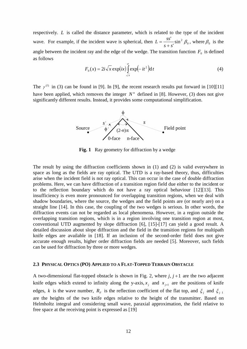
Fig. 1 Ray geometry for diffraction by a wedge The result by using the diffraction coefficients shown in (1) and (2) is valid everywhere in space as long as the fields are ray optical. The UTD is a ray-based theory, thus, difficulties arise when the incident field is not ray optical. This can occur in the case of double diffraction problems. Here, we can have diffraction of a transition region field due either to the incident or to the reflection boundary which do not have a ray optical behaviour [12][13]. This insufficiency is even more pronounced for overlapping transition regions, when we deal with shadow boundaries, where the source, the wedges and the field points are (or nearly are) on a straight line [14]. In this case, the coupling of the two wedges is serious. In other words, the diffraction events can not be regarded as local phenomena. However, in a region outside the overlapping transition regions, which is in a region involving one transition region at most, conventional UTD augmented by slope diffraction [6], [15]-[17] can yield a good result. A detailed discussion about slope diffraction and the field in the transition regions for multipath knife edges are available in [18]. If an inclusion of the second-order field does not give accurate enough results, higher order diffraction fields are needed [5]. Moreover, such fields can be used for diffraction by three or more wedges. 2.3 PHYSICAL OPTICS (PO) APPLIED TO A FLAT-TOPPED TERRAIN OBSTACLE A two-dimensional flat-topped obstacle is shown in Fig. 2, where 1, �jj are the two adjacent
knife edges which extend to infinity along the y-axis, jx and 1�jx are the positions of knife
edges, k is the wave number, FR is the reflection coefficient of the flat top, and j� and 1�j�
are the heights of the two knife edges relative to the height of the transmitter. Based on Helmholtz integral and considering small wave, paraxial approximation, the field relative to free space at the receiving point is expressed as [19]
Source Field point
0-face n-face
�
� '
s ' s
(2-n)�

13
� ����
�
� ��
��
����
�
�� ��
��
��
�
��
�
jikr
Fjjjikr
jjjj
jjj dzRzxEdzzxE
x���
kxzxE
jj
'2
1
111 e),(e),(
2,
��
(5)
where
2
11
1
2 ���
����
��
��
�
�
�
jj
jj
jj
j zx
xz
xx
xr (6)
where jjj xxx ���
�1 , jxhhrr ��� 212' and jjzh ���1 , 112 ���� jjzh � .
Fig. 2 The problem of finding the field at P due to a Huygens’ point source at Q 2.4 THE NEW APPLICATIONS OF PO FOR TERRAIN FIELD STRENGTH PREDICTION Based on the work of [19][20], attenuation by double knife edges with ground reflections, attenuations by curvilinear-topped obstacles and multiple flat-topped obstacles are solved in [P1] and [P2], respectively. 2.4.1 Attenuation by multiple knife edges with ground reflections As shown in Fig. 3, assume that there are N knife edges and that at the interval ( jx , 1�jx ) the
reflection coefficient is 1�FjR . The time dependence is given by ti��e , where i is the imaginary
unit. From (5) and with some mathematical transformations, the field relative to free space at point R can be derived as
Fig. 3 Geometry for calculating knife-edge diffraction with ground reflections
... ...
... ...T R
z
x
TH 1H
0x1x
Nx 1�Nx
NHRH
1FR ... ...1�FjRjx 1�jx
1�jHjH
Q
P
R
.�
�
j
j+1
xj xj+1
xj�
h1
h2x
zo

14
� � �� � �
�
��
�
���
����
�
����
���
��1 2
21
2
1
11
12
1,1 2)(
H H H
NN
N
N
NN
N
dzdzdzxxx
x
��
kzxE ��
�
� � )7()'exp()exp(2
exp11
11
11 �
�
��
���
�
���
���
���
�
N
jjFjj
TF ikrRikr
x
HzikR
where
2
11
1 )(2 �
��
�
����
��
�
�
�
Tjj
jTj
jj
jj Hz
x
xHz
xx
xr (8)
j
T
j
TjjTj
j
jTj
jj
jj x
H
x
HzzHz
x
xHz
xx
xr
��
�
��
���
�
����
�� �
�
�
�
21
2
11
1 2)(2)(
2' (9)
where HT , HR and H1 , H2 , �, HN are the heights relative to ground for the transmitter, receiver and multiple knife edges, respectively. In [P1], the attenuation of double knife edges with ground reflections is solved. The final received field is the sum of eight field components and each contains the Fresnel surface integral
dudvvu�
ii
q nmvu� �� �
��
��
�
� ���
���
��0
)(2
exp2
22 (10)
where q , 0u , m and n are constants. Based on numerical calculations in [P1], the multipath field components can be reduced by locating where is the main reflection point. The surface reflection (if exists) cannot be neglected between the last knife edge and the receiver where it is in the diffraction region. The solutions of (10) can be found [14][20][21]. 2.4.2 Attenuation by curvilinear-topped obstacles and multiple flat-topped obstacles For a curvilinear-topped obstacle, the relative field of attenuation was also solved in [22], but a complicated series was included in the final results. In [P2], a quite simple and symmetrical result is derived. The relative field of attenuation by multiple flat-topped obstacles is solved in the similar way as that of a curvilinear-topped obstacle [P2]. Fig. 4 and Fig. 5 show the geometries for a curvilinear-topped obstacle and multiple flat-topped obstacles, respectively. For the curvilinear-topped obstacle shown in Fig. 4, the edges of the polygon should be long enough to satisfy the paraxial approximation in [19]. The field of attenuation relative to free space of multiple knife edges was solved in [1] and let us denote it
as )(RE�
. In [P2], the total field is given as the sum of N2 field components for a curvilinear-topped obstacle with N reflection surfaces where the reflection coefficients can be regarded as constants. For example, if 3�N , the eight field components are derived to be as follows

15
Fig. 4 Geometry for diffraction by a curvilinear-topped obstacle
Fig. 5 Geometry for diffraction by multiple flat-topped obstacles The definition of j� )3,2,1( ��j in (11) is available in [1], and the Vogler’s multiple knife-
edge field of attenuation )(RE�
includes the repeated integrals of the error function ),( �nI which is expressed as
� � � �dxxxn
nI n
��
����
��
� 2exp!
2),( (12)
The solution of (12) can be found in [23]. For N multiple flat-topped obstacles, the total field is also the sum of N2 field components, which have quite similar expressions as (11) and can be found in [P2].
),,()()( 3211 ������
�� ERERE (11a)
),,()( 32112 ���� ���
ERRE F (11b)
),,()( 32123 ��� � ���
ERRE F (11c)
),,()( 32134 ��� � ���
ERRE F (11d)
),,()( 321215 ��� �� ���
ERRRE FF (11e)
),,()( 321326 ��� �� ���
ERRRE FF (11f)
),,()( 321317 ��� �� ���
ERRRE FF (11g)
),,()( 3213218 ��� ��� ���
ERRRRE FFF (11h)
. . .
. . .
h0
h1 h2 hh
N
N+1
r1 r r2 N+1
=hT =hR
F1 RF2 RFN-1
R
T R
h0
h1 h2
h
hN-1
N+1
r1 r r2 N
=hT =hR. . .
3 h4
r r3 4
h hN
rN+1
. . .
T R

16
3. MULTIPATH PROPAGATION STUDIES FOR TERRESTRIAL MICROWAVE
COMMUNICATIONS
3.1 INTRODUCTION The super-refractive layer formed in the lower atmosphere can completely reflect the radio wave in a terrestrial microwave communication link. This causes multipath propagation and may cause destructive interference at the receiving antenna. The multipath propagation causes frequency selective fading (FSF) which is regarded as in-band amplitude dispersion and it is the main factor of the quality degradation for medium and high capacity digital microwave communication systems [24][25]. The multipath propagation caused by an atmospheric duct is also one of the main factors of deterioration for cross-polarization discrimination (XPD) in dual polarized microwave communication systems [25][26]. 3.2 THE ATMOSPHERIC DUCT AND THE METEOROLOGICAL CONDITION An atmospheric duct means a layer, which can completely reflect the radio waves in lower atmosphere. The condition for the to formation of the atmospheric duct is that the refractive index gradients satisfy /10157 6����dzdn km (13) If we use the concept of refractivity 610)1( ��� nN , then the duct condition is 157��dzdN N unit / km (14) Eqs. (13) and (14) are for the spherical earth. If the plane earth case is considered, then the modified refractive index m and modified refractivity M should be introduced. The condition to form the atmospheric duct in the plane earth case is now as follows 0�dzdm (15) 0�dzdM (16) The relationship between M and m is 610)1( ��� mM .
Fig. 6 Height profile of the modified refractive index
z
m
G
G0
layer
hG0

17
Fig. 6 shows how the modified refractive index changes with height. From this curve it is obviously seen that the atmospheric duct appears at the heights between 1h and 2h , because
dhdm is negative. 3.3 THE CUMULATIVE DISTRIBUTIONS FOR REFRACTIVE INDEX GRADIENTS IN LOWER ATMOSPHERE The cumulative distribution of the refractive index gradient dhdn in lower atmosphere changes with different seasons, regions and meteorological conditions. Based on data observed over many years, Yang et al. [27] showed that exponential and normal distributions have good agreement with the refractive index gradients inside and outside the layer, respectively. Therefore, inside the layer the cumulative distribution function (CDF) of the refractive index gradient G is
���
��� �
��V
SGGGP
3
)(4exp
2
1)'( (17)
where parameters S and V can be fitted by using observed data. Outside the layer G0 has the distribution
��
���
��
��� �
��
�
�2erfc
2
1)'( 00
0
GGGGP (18)
where 0
�
G and � are the mean value and standard deviation, respectively, which can also be
derived from the observed data. The parameters S , V , 4 and 3 in (17), 0
�
G and � in (18) have no special meanings, they are just fitted or extracted from the measured data. 3.4 EXPERIMENTAL AND COMPUTER SIMULATION STUDIES OF FREQUENCY SELECTIVE FADING 3.4.1 Transfer function of multipath channel In [P3], according to ray-based theory, the multipath power transfer function can be expressed as
� �)(sin2
)cos(2)sin(2)()(
2332
3312212
32
22
1
2
��
��
��
������
aa
aaaaaaafHfPr (19)
where 1a , 2a and 3a are the amplitudes for the direct, super-refractive and reflection rays,
respectively. In the frequency selective fading studies, the plane earth is considered here. Therefore, the modified refractive index and its gradient have been used in simulations. G and 0G are the
modified refractive index gradients outside and inside the layer, respectively. From (19), the

18
power transfer function of the channel is related to the delays and amplitudes of the rays. By using the ray tracing method, the excess delay is a function of G and 0G for the super-
refractive ray and function of 0G for both direct and reflected rays [P3].
The normalized radiation pattern of the parabolic antenna used in this thesis is [28]
� �
�
���
sin�
sin�
)cos1()( 1
A
A
D
DJF �� (20)
where AD is the aperture diameter, � is off-axis angle and )(1 J is the Bessel function of the first kind. The amplitude of the direct ray is set to unity, so the amplitudes of the super-refractive and reflected rays are )()( 002 R
RT
T FFa ���� � �� (21)
and )()(3 R
ReT
Tee FFRa ���� � � � (22)
where T� and R� , T
0� and R0� , T
e� and Re� are the transmitting and receiving angles of the
direct, super-refractive and reflected rays, respectively, and they are functions of G and 0G or
0G [P3]. eR is the effective ground reflection coefficient, which is affected by the spreading
factor of the earth and the roughness s� of the ground [29]. s� is calculated by
� � 972.322.3
1)exp()(
20
���� ��
� Is (23)
2
222 sin�8
�� h� (24)
Here )(0 I is zero order modified Bessel function, h� is standard deviation of the ground
roughness in the first Fresnel region near the mirror reflection point, and � is angle between incident ray and ground. 3.4.2 Computer simulation method The excess delays and amplitudes in (19) are functions of G and 0G or 0G , which are random
variables with distributions given by Eqs. (17) and (18), and the samples of G and 0G can be
generated by the following equations
� � SVRWG � � 2ln4
3 (25)
� �_
0210 2cosln2 GRRG � �� �� (26)

19
where � �VSW 34exp21 � � and R , 1R and 2R are uniformly distributed random numbers in
[0,1]. Let us assume that the center frequency and the bandwidth of the microwave link are 0f
and f� , respectively. Depending on the bandwidth and center frequency, the odd number of
the narrow band channels are assigned during the simulation and let 1f , �2f , nf denote the
center frequencies of the narrow band signals. The flow chart of the computer simulation is shown in Fig. 7, where hZ , lZ and Z are the in-band dispersions for the upper and lower
antennas and for diversity reception, respectively. In the simulation, five narrow band channels are used corresponding to the channels in the experiments.
Fig. 7 Flow chart of the computer simulation
start
RN in [0,1]
normal RN exponential RN G
G<G0?
Yes
No
No
G<0 ?
upper ant. lower ant.
narrow-band channels narrow-band channels
. . . . . .f1
f2
f n
f1
f2
f n
in-band dispersion Z =20log{abs[H( f )]}
h i
in-band dispersionZ =20log{abs[H( f )]}
l i
space diversityZ=min ( Z , Z )h l
statistics of statistics of statistics ofZ Zh l
stop
Z
G0
RN: random number

20
3.4.3 Measurement setup The measurement setup is shown in Figs. 8(a) and 8(b). The signal is received by using frequency conversion to the intermediate frequency amplifier (IFA). The IFA has two outputs: one goes to A/D conversion and finally to the computer for detecting flat fading. Another output goes to a narrow-band receiver, whose five narrow-band signal outputs at different frequencies are stored by the computer. The main parameters of the narrow band receiver are: number of channels 5; center frequencies 57.7, 64.7, 70, 75.7 and 81.9 MHz; frequency interval 5.3 ! 7 MHz; bandwidth 15 ! 20 kHz; dynamic range 40 dB; channel isolation "50 dB and measurement accuracy 1 dB.
(a)
(b)
Fig. 8 The measurement setup. (a) The transmitting system. (b) The receiving system.
PN-gen. digitalmodulator
transmitter
frequencyconversion
frequencyconversion
IFamplifier
IFamplifier
digitaldemodulator
BERanalyzer
digitaldemodulator
BERanalyzer
detector
detector
narrowband receiver
narrowband receiver
A / D computer
21
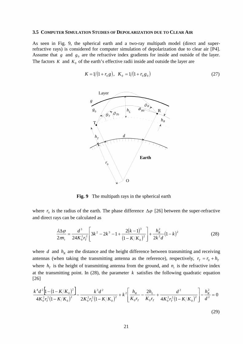
3.5 COMPUTER SIMULATION STUDIES OF DEPOLARIZATION DUE TO CLEAR AIR As seen in Fig. 9, the spherical earth and a two-ray multipath model (direct and super-refractive rays) is considered for computer simulation of depolarization due to clear air [P4]. Assume that g and 0g are the refractive index gradients for inside and outside of the layer. The factors K and 0K of the earth’s effective radii inside and outside the layer are � �grK 011 �� , � �000 11 grK �� (27)
Fig. 9 The multipath rays in the spherical earth
where 0r is the radius of the earth. The phase difference �� [26] between the super-refractive
and direct rays can be calculated as
� �
� �� �2
2
2
20
332
220
3
121
12123
242k
dk
h
KK
kkk
rK
d
nR
Tt
�����
�
�
�
�����
��
� (28)
where d and Rh are the distance and the height difference between transmitting and receiving
antennas (when taking the transmitting antenna as the reference), respectively, TT hrr �� 0
where Th is the height of transmitting antenna from the ground, and tn is the refractive index
at the transmitting point. In (28), the parameter k satisfies the following quadratic equation [26]
� �� �� � � � � �
014
2
1214
112
2
20
220
2
00
22
022
0
23
20
220
20
24
�����
�
�
����
��
�
��
d
h
KKrK
d
rK
h
rK
hk
KKrK
dk
KKrK
KKdk R
TT
L
T
R
TT
(29)
d
T
R
r0
hT
hR
hL
O
� T� T0
� R0
� R
g
g0
Layer
Earth

22
where Lh is the height of the lower boundary of the layer above the transmitting point. Assume that the cross polarization pattern of an antenna is [26]
� �� � � �
� � � ���
��
�
#
�
�
ccx
cx
cf
cf
f
���
���
�22
22
2
exp0
exp0
(30)
where � is the polar angle relative to the axis of the antenna, and xc and c� are constants
which can be fitted by using the measured cross polarization pattern of the antenna. The static cross-polarization discrimination is defined as XPD 0 � �)0(2log20 10 f�� (31)
In (30), the )0(f can be derived from (31). The cross polarization discrimination (XPD) can be calculated as [26]
XPD� �
� �� � � � � �� �� � � �� �� � ����
�
��
��
�
����
�
20
20
20
20
210
exp5.0exp2exp)0(
cos12log10
TTxTTRRxRRx cccf ��������
�
� �� � 000 ,,,,,, TTcxTTRR c0f ��������� �� �� and cRR ��� �� 0 (32)
where 0T� and 0R� , and T� and R� are the transmitting and receiving angles for both the
direct and super-refractive rays, respectively. When 0TT �� � and 0RR �� � are in the other
intervals shown in [P4], the XPD can also be calculated by changing the parameters in the function � . The co-polarized attenuation (CPA) is calculated as CPA � �� ������ cos12log10 10 (33) From (28), (32) and (33), it is seen that XPD and CPA are functions of the factors of the earth’s effective radii K and 0K , namely XPD and CPA change with the refractive index gradients g
and 0g inside and outside the layer. The distributions and the sample generation for g and 0g
are similar in Sections 3.3 and 3.4.2. By using (32) and (33), the statistical distributions of XPD and CPA can be obtained by computer simulations. The simulation and experimental studies of depolarization due to multipath propagation in [P4][30] show that the equal probability values of XPD and CPA have a linear relationship. The slope is within (-1, 0) and not always equal to 1� as suggested by ITU-R recommendation [31]. This linear relation enables us to introduce a simple and valuable method for predicting XPD based on the prediction of CPA.
23
4. PROPAGATION CHARACTERIZATION OF RADIO CHANNELS FOR FUTURE WLAN
MOBILE COMMUNICATION SYSTEMS
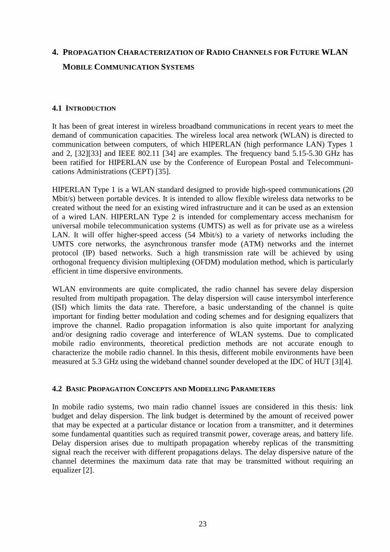
4.1 INTRODUCTION It has been of great interest in wireless broadband communications in recent years to meet the demand of communication capacities. The wireless local area network (WLAN) is directed to communication between computers, of which HIPERLAN (high performance LAN) Types 1 and 2, [32][33] and IEEE 802.11 [34] are examples. The frequency band 5.15-5.30 GHz has been ratified for HIPERLAN use by the Conference of European Postal and Telecommuni-cations Administrations (CEPT) [35]. HIPERLAN Type 1 is a WLAN standard designed to provide high-speed communications (20 Mbit/s) between portable devices. It is intended to allow flexible wireless data networks to be created without the need for an existing wired infrastructure and it can be used as an extension of a wired LAN. HIPERLAN Type 2 is intended for complementary access mechanism for universal mobile telecommunication systems (UMTS) as well as for private use as a wireless LAN. It will offer higher-speed access (54 Mbit/s) to a variety of networks including the UMTS core networks, the asynchronous transfer mode (ATM) networks and the internet protocol (IP) based networks. Such a high transmission rate will be achieved by using orthogonal frequency division multiplexing (OFDM) modulation method, which is particularly efficient in time dispersive environments. WLAN environments are quite complicated, the radio channel has severe delay dispersion resulted from multipath propagation. The delay dispersion will cause intersymbol interference (ISI) which limits the data rate. Therefore, a basic understanding of the channel is quite important for finding better modulation and coding schemes and for designing equalizers that improve the channel. Radio propagation information is also quite important for analyzing and/or designing radio coverage and interference of WLAN systems. Due to complicated mobile radio environments, theoretical prediction methods are not accurate enough to characterize the mobile radio channel. In this thesis, different mobile environments have been measured at 5.3 GHz using the wideband channel sounder developed at the IDC of HUT [3][4]. 4.2 BASIC PROPAGATION CONCEPTS AND MODELLING PARAMETERS In mobile radio systems, two main radio channel issues are considered in this thesis: link budget and delay dispersion. The link budget is determined by the amount of received power that may be expected at a particular distance or location from a transmitter, and it determines some fundamental quantities such as required transmit power, coverage areas, and battery life. Delay dispersion arises due to multipath propagation whereby replicas of the transmitting signal reach the receiver with different propagations delays. The delay dispersive nature of the channel determines the maximum data rate that may be transmitted without requiring an equalizer [2].
24
Small scale and large scale fading: Due to multipath propagation, when a mobile moves over short distances, the instantaneous received signal strength fluctuates rapidly giving rise to small scale fading. As the mobile moves away from transmitter, the local average of the received signal will decrease gradually. For the macro-cellular case, it was proven in [36] that 20 to 40 � (wavelength) is most suitable window length or sector length to average fast fading components. For the micro-cellular case at 900 MHz, 5� (about 1.7 meters) has been shown feasible based on measurements [37]. At 5.3 GHz, it is shown in this thesis that 20 – 40� (about 1.1 – 2.3 meters) is the best window lengths based on large amount of measured data in outdoor and indoor environments [P5][P6]. Therefore, it is recommended that the practical window length for averaging small scale fading is 1 – 2 meters in micro- and pico-cells at 900 MHz – 5 GHz frequency bands. In [P5], the boundaries of the window length were empirical and based on the comparisons of the minimized standard deviations, however, the upper boundary cannot be more than 40� . Path loss: Path loss is an important parameter for not only predicting the coverage area, but also for predicting the interference signals that a user will experience from other RF sources. Path loss can be derived by using the following formula to fit the measured data [38][39][P6] �XddndPLdPL ��� )/(log10)()( 01000 (34)
This is called lognormal shadowing path loss model, where n is the path loss exponent, 0d is
the reference distance which should always be in the far field of an antenna in free space. d is the distance from the transmitter to receiver and �X is zero mean Gaussian random variable
with standard deviation (STD) � . Typically, 0d equals 1 km for large urban mobile systems,
100 m or 1 m for micro-cellular systems [38]. The empirical path loss models can also be derived by using a two-parameter (both n and 0PL
are variables) least square method [40]-[42][P5], dnPLdPL 100 log10)( �� (35)
where there is no reference distance and d is in meters. In semi-log coordinates, 0PL is the
intercept point at the vertical axis and n is the slope. The least square method has been applied in the path loss models shown in (34) and (35) when deriving the empirical path loss models from measured data. In (34), the reference free space distance 0d should be decided first when using the models. However, the mobile environments
are quite complicated and it is hard to know what 0d exactly is for a specific environment. The
same reference distance for all macrocells or microcells is obviously not quite reasonable. Therefore, in practical applications, (35) can give better fit to measured data with lower STD [P5]. In order to reduce the fitted STD when using (34) and (35), line-of-sight (LOS) and non-line-of-sight (NLOS) situations should be distinguished. In the LOS case, the break point should be noticed, because at it the path loss exponent changes a lot. The distance of the break point from
25
the base station is approximately equals to BM hh4 , where Mh and Bh are the antennas heights for the mobile and base station from ground level [43]. The path loss model for multiple floors and multiple walls (Motley Keenan model) is also available in [44]. The path loss is strongly dependent on the structures and not a linear function of the numbers of the walls and floors. Guided wave effect: In many LOS corridors and street canyons, the received power is found to be higher than that in free space in [P5][P6] and also in [38][39]. This phenomenon is called guided wave effect. Due to the fact that the energy of the propagating waves is confined in the waveguides, so it cannot spread in every direction like in free space. In such corridors and street canyons, some dominant propagation models are existed, and they depend on the dimensions of the waveguides and the frequency bands of propagating waves. Delay spread: Mobile radio channel has delay dispersion due to multipath propagation. Because the multipath propagation is dependent upon the geometric relationships between transmitter and receiver, and the surrounding physical environment, the delay dispersion appears random. Therefore, statistical parameters such as mean excess delay and rms delay spread etc. are often considered. In delay domain, the power delay profile, which is a function of excess delay, and average received power can be measured by a channel sounder. The mean excess delay is the first central moment of the power delay profile and rms delay spread is the standard deviation of the excess delays. The rms delay spread is a most important modelling parameter which is connected to the capacity and the bit-error-rate (BER) of a specific communication system and the complexity of a receiver. Results in [45][46] show that the error floor is approximately proportional to the square of the normalized rms delay spread, namely
the BER is equal to � �2TSK , where the proportionality constant K depends on the modulation format, the filtering at the transmitter and receiver, and the sampling time, S is the rms delay spread and T is the symbol duration. This dependency between BER and rms delay spread is true, however, only under some special assumptions [47][48]: The maximum excess delay of the channel must be much smaller than the symbol length, and the channel must be Rayleigh fading. For a given BER, by comparing the rms delay spread and the symbol duration, one can determine if any equalizer is required in the receiver. Spatial and frequency correlations: Spatial and frequency correlation studies are useful for the design of antenna diversity to reduce multipath fading. The formulas for calculating spatial and frequency correlation functions can be found in [49][P6]. Because the correlation behaviour is a small scale effect, the wide sense stationary uncorrelated scattering (WSSUS) should be assumed. To meet this condition, 100 - 200 IRs (about 20 - 40 wavelengths) are used as the window length to calculate the correlation functions and finally an average correlation function can be obtained. In this thesis, envelope correlation is considered for narrowband signals. However, recent research [50] has shown that spatial correlation characteristics do not largely depend on frequency bandwidth up to approximately 20% of the carrier frequency. Therefore, the narrowband model is sufficient for calculating the signal correlation characteristics within cfB 2.0� , where B is the bandwidth of a transmitted signal and cf is
the carrier frequency. At 5.3 GHz, the studies in [P5] show that the correlation is strongly dependent on the transmitter height and LOS and NLOS situations in different environments.
26
Path number distribution: Poisson’s and modified Poisson’s distributions were considered for the multipath number in [51]. Modified Poisson’s distribution was shown to have good agreement with the experiment results in some cases. However, modified Poisson’s distribution does not have an explicit expression, but is just a process. Therefore, it’s not convenient for practical use. In [52][53], another simple and useful path number distribution was introduced by considering the path number variation of radio waves in land mobile communications to be a Markov process at finite state space, and it was shown to have good agreement with the experimental results. The path number distributions given by Poisson and Gao [52][53] can be expressed as
���
�
�� e
NNNP
T
NNT
)!()( (36)
� � T
T
T N
NNNNCNP
�
�
��
�
1)( (37)
where N is a variable, C means combination, and the maximum number of paths that mobile can receive is TN . The parameters � and TN can be found by fitting into the experimental
data. For Poisson’s probability density function (PDF), the mean path number is ��N . For
Gao’s PDF, the mean value is )1( ��� TNN . It is shown in [P5] that both Poisson’s and
Gao’s PDFs have good agreement with the experiment results. However, Gao’s PDF has better fit especially at high probability values. In [P5], the path numbers are obtained by counting the peak values in the PDPs, however, some other methods such as CLEAN algorithm [54] might be used in further studies. Amplitude distribution and Ricean K-factor: There are several amplitude distributions such as Rice, Rayleigh, Nakagami (also called m-distribution), lognormal and Suzuki distributions [55] to describe both narrowband and wideband signals. The Nakagami distribution contains many other distributions as special cases. The Suzuki distribution is a mixture of Rayleigh and lognormal distributions. The lognormal distribution has often been used to explain large scale variations of the signal amplitudes in a multipath environment. For wideband radio channel studies at 5.3 GHz in this thesis, Rice and Rayleigh distributions are proven to be the best to characterize the envelope amplitude. A well accepted model for small scale rapid amplitude fluctuations in absence of a strong received component is the Rayleigh fading. However, when a strong path exists in addition to the lower level scattered paths, Ricean fading appears. This strong components may be a LOS path or a path that goes through much less attenuation compared to other arriving components. The Rice distribution can be characterized by Ricean factor which is defined as follows 22 2�sK � (38) where 2
� is average fading power of the non-dominant paths and s is the peak amplitude of the dominant received multipath component. There are several methods for estimating K -factor from measured data [56]-[59]: method of least square, moment method (MoM) and method of maximum likelihood (ML). The least square method is a traditional method which

27
directly uses measured data to fit Rice distribution while the standard deviation is minimized. There are two formulas based on MoM which can give a quick estimation of the K -factor called � -based method and � -based method [57]
� �)2(I)2(I)1()2exp()1(2 10
21 KKKKKK �� ��� ��
� (39)
2)1(
12
�
��
K
K� (40)
where � � � �2AEAE�� and � � � �� �222 AEAV�� with � �.E denoting the expected value and
� �.V the variance. A is the received signal envelope. Eqs. (39) and (40) are quite simple for practical use. However, the studies in [57] show that for low mobile speed which introduces significant correlation among signal samples, the estimators’ performance becomes deteriorated due to the reduction in the number of independent samples. In this thesis, the least square method has been applied [P6][P7]. 4.3 TAPPED DELAY LINE CHANNEL MODELS The following parameters should be specified when developing a tapped-delay-line channel (TDL) model [60][P6][P7] $ Number of taps $ Excess delays of the taps $ Relative amplitudes of the taps $ Amplitude distributions of the taps $ Doppler spectra of the taps $ Correlation between consecutive taps Fig. 10 Principle of RAKE receiver [61]. When a TDL model is developed, it gives the radio channel transfer function. Therefore, some anti-fading measures can be adopted, e.g. using an equalizer or a RAKE receiver shown in Fig.
Code generator
Modulator
%2 a 2
%1 a 1
% 3 a 3
Multipath channel
De-modulator
a 1
a 2
a 3
c(t-%�)
c(t-%�)
c(t-%�)
RAKE receiver
Binary data

28
10. The RAKE receiver consists of correlators, each receiving a multipath signal. After despreading by correlators, the signals are combined using, for example, maximal ratio combining. In [P6] and [P7], based on some basic theories introduced in [60], tapped-delay-line (TDL) models for indoor and outdoor mobile communications are developed for the first time at 5.3 GHz frequency band. The TDL models with 4, 5 and 6 taps are considered. For an equalizer, 4 or 5 taps seems currently the maximum which is practically realizable [48]. 4.4 PROPAGATION MECHANISM STUDIES FOR DIFFERENT TYPES OF DOPPLER SPECTRA Considering Doppler spectrum studies, important models were presented by Clarke [62] and Aulin [63] which are typical 2- and 3-D models, respectively. It has been shown that 3-D Doppler spectra are suitable to describe indoor as well as outdoor mobile communications when base station antenna height is over rooftop [64]. In this case the Aulin, Gaussian, Laplacian, double-sided exponential and other PDF models have been used to describe the angles of arrival (AoAs) of the scattered waves in the elevation plane [63]-[67]. In both 2- and 3-D cases, it is often assumed that the AoAs of the scattered waves in the azimuth plane are uniformly distributed in � ��2,0 . However, in some practical propagation environments [68],
the AoAs have been found to be distributed in an arbitrary angular range � �21,�� . Meanwhile in the elevation plane, the AoAs can also be assumed to be distributed in another arbitrary angular range � �21,�� . In some papers [61][69][P6], the names of Doppler spectra have been given, but there is some lack in explaining the physical background in terms of propagation mechanisms for more general AoAs distributions in the azimuth and elevation planes. 4.4.1 Formulation of theoretical Doppler spectrum modelling Assume that mobile radio channels are WSSUS and a mobile terminal is moving along a straight line in xy-plane as shown in Fig. 11. In [P7], an autocorrelation function is derived as
� �� � � �� �
���� ����������� cos)cos(exp)()()()()( vjkddgPgPR (41)
where )(��P and )(��P are the PDFs of the AoAs of the scattered waves in the azimuth and
elevation planes, respectively, and )(��g and )(��g are normalized antenna radiation patterns
in the planes. The definition of angles l� and l� for l-th multipath ray is shown in Fig. 11. The
2-D and 3-D autocorrelation functions can be derived from (41) by assuming that the mobile moves along x-axis ( 0�� ) for simplicity. By applying Fourier transformation to the autocorrelation function, the corresponding Doppler spectral density is obtained by
���� dfjRfS DD )2exp()()( �� ��
��
(42)
where Df is the Doppler shift.

29
Fig. 11 Geometry for a 3-D scattered environment 4.4.2 Empirical Doppler Spectrum modelling Empirical Doppler spectra are derived in [P6][P7] using the delay Doppler function or scattering function ),( ��U [70]
dtethU tj ����� 2),(),( �
�
��
�� (43)
where � denotes the Doppler frequency. The Doppler spectrum is due to small scale effect, so WSSUS radio channel should be assumed. This is satisfied by choosing sets of 100 IRs (about 1.1 meter) from the collected IRs to get instantaneous samples of the Doppler spectrum, and finally the average Doppler spectrum is obtained for a specific mobile environment. 4.5 A GENERAL COMPUTER SIMULATION METHOD FOR 3-D RECEIVED SIGNAL LEVEL IN WIDEBAND MOBILE COMMUNICATIONS In this thesis, we extended the 2-D work shown in [71][72] to 3-D case under general and reasonable assumptions. These are that the path number has Poisson distribution, multipath amplitudes follow Rayleigh or Rice distribution, the AoAs in both of the azimuth and elevation planes follow uniform and Gaussian distribution, respectively, and excess delay follows exponential distribution. The 3-D received power for wideband signal was expressed as
� � � ���
��
�
��
��
� �� & &&
� �
�
�
N
i
N
i
N
ijj
ijijcjii LfKLKfAAAffP1 1 1
2 sinccos2)( ����� (44)
scatterer
mobile'
( lx
y
z
)
l
* l

30
where f�2 is the bandwidth of transmitted signal with carrier frequency cf , iA and jA are the
amplitudes of scattered waves, cK /2�� and c is the speed of light. Let us assume that the mobile is surrounded by scatterers and is moving along the x-axis with a speed v, as shown in Fig. 12. In the 3-D case, the path length difference can now be expressed as � � � �jjiijijijiij vtLLvtLLL ������ coscoscoscoscoscos � ���� ���� (45)
where iL and jL are path lengths for the i-th and the j-th waves at the starting point O,
respectively [72], and tnt �� ( t� is the time step). In (45), let us define � � )()()( minmin jijijiij ccLcLcLcLcLLL �� �������� (46)
where minL is the minimum path length, i� and j� are excess delays for the i-th and j-th
waves. Fig. 13 presents the flow chart of the simulation performed in this work. The input parameters of the simulation and simulation results are available in [P8] for wideband and narrowband received signal levels. Severe time selective fading can be observed for wideband received signal when signal amplitudes follow Rayleigh distribution. Fig. 12 Geometry of 3-D propagation
Y
X
Z
O
�+i
�i�j
�i
mobile
ith wavejth wave
vt
Li
Lj

31
Fig. 13 Flow chart of the computer simulation 5. SUMMARY OF PUBLICATIONS In [P1], a general formula of the attenuation by multiple knife edges with ground reflections is derived and further the field of attenuation for double knife edges with ground reflections is solved for the first time in the paper by using physical optics. The total field includes eight field components, but the number of these components can be reduced by locating the main reflection point. The fluctuation of the received field in the illumination region is due to the reflection from the region at where the main reflection point is located. The received field fluctuation in the diffraction region is due to the reflection from the area between the last knife edge and the receiver. In [P2], by using physical optics and implementing complicated integral transformations, attenuations by curvilinear-topped obstacles and multiple flat-topped obstacles are solved by summing N2 field components, where N is the number of the curvilinear lines or flat-topped obstacles. The results derived are the simplest and easiest ones presented for practical use. To calculate the field components one just needs to change the signs of j� ( �,3,2,1�j ) in
Vogler’s formula for the attenuation by multiple knife edges.
Poisson RN for N
Rayleigh or Rice RN for A
Uniform RN in [0,2�� for �
Gaussian RNin [ � � ] for �
Exponential RN for
Equation (44)
STOP
START
�
i
i min, max
i
i
n=1n=n+1
t=n �t
RN: random number
32
In [P3], a novel simulation method is introduced and applied to frequency selective fading by using a three-ray multipath model with the assumption of a plane earth. Based on measurements and simulations, flat fading, in-band dispersion and space diversity effect are studied in detail. The excess delays and the amplitudes of the rays are derived as functions of the modified super-refractive index gradients inside and outside the layer. The gradients are random variables which form the basis of simulation. The correlation between flat fading and in-band dispersion is also studied, which offers an effective way to predict in-band dispersion using flat fading. A similar simulation method compared to the method introduced in [P3] is also applied in [P4] to study the depolarization effects due to clear air by using a two-ray multipath model with a spherical earth. Based on some formulas derived in [26] and [P4], the statistical distributions of cross-polarization discrimination and co-polarized attenuation, and the relationship of their equiprobability values are simulated. In [P5] and [P6], the latest propagation parameters and models are provided at 5 GHz. These are of great importance in designing future WLAN mobile communication systems. Especially the tapped-delay-line channel models are developed for the first time in this frequency band. To get the results, in [P5], a large outdoor measurement campaign at 5.3 GHz was performed in Helsinki in 1999 with different base station heights in urban, suburban and rural environments. Based on the measured database, empirical or semi-empirical models and parameters are derived. These include path loss models, excess delay and rms delay spread, window length for averaging fast fading components, spatial and frequency correlations and path number distributions. Rotation measurements were also performed with a directive horn to study spatial propagation mechanisms and directions of arrival of multipath rays. In [P6], empirical models are developed for typical office environments and one large hall with mainly omni-directional antennas at 5.3 GHz. Empirical models and parameters such as path loss models, tapped-delay-line channel models, rms delay spread, spatial and frequency correlations are developed/derived for indoor environments. In [P7], a novel theoretical modelling method has been introduced to explain the physical backgrounds of measured Doppler spectra in 3-D scattered environments from propagation mechanism point of view. First, a general 3-D autocorrelation function is derived in a 3-D scattered environment with the assumption of WSSUS radio channel. It is related to the PDFs of the AoAs of the waves and antenna radiation patterns in both of the azimuth and elevation planes. By applying Fourier transformation to the autocorrelation function, the corresponding power spectral density can be obtained. In [P8], a new and general method is introduced to simulate 3-D wideband received signal level in urban environments. Some distributions for the path number, amplitude, the AoAs in the azimuth and elevation planes and excess delay have been applied for simulation purpose. However, they can be replaced by more accurate and new research results of the distributions.

33
6. CONCLUSION The analytical expressions for the fields of attenuation by some typical-shaped terrain obstacles are derived in this thesis. These can be applied in field strength predictions not only to terrestrial fixed and mobile communications, but also to some radar systems in frequency bands higher than VHF. The double knife-edge attenuation with ground reflections is solved for the first time in the case where the reflection coefficients can be regarded as constants. The fields of attenuation by curvilinear-topped obstacles and multiple flat-topped obstacles are also solved in closed forms, which are the simplest and easiest ones available at the moment for practical use. Computer simulation is an effective way to study frequency selective fading and depolarization effects for terrestrial microwave links and dual polarized communication systems. In this work, novel simulation methods are introduced and applied to these research fields. It is illustrated that diversity reception reduces significantly flat fading and in-band dispersion. Fading and dispersion are severe during small percentage of time. The in-band linear amplitude dispersion, as well as the in-band maximal amplitude dispersion, have a relatively high correlation. The equiprobability values of in-band linear amplitude dispersion and flat fading depth have an excellent linear relationship with the slope less than unity. This linear relationship enables us to introduce a simple and useful method for predicting the frequency selective fading by means of the flat fading. In this thesis, the cross-polarization discrimination and co-polarized attenuation statistical distributions are also simulated due to clear air. The equiprobability values of the cross-polarization discrimination and co-polarized attenuation shown in the simulation and experiment have a linear relationship with slope within ( 1� , 0) and does not always equal 1� as stated in ITU-R recommendation. The latest modelling parameters and models are presented in this work for outdoor and indoor mobile communications at 5.3 GHz. The modelling results based on the outdoor measurements at 5.3 GHz show that the path loss exponents are within 1.4 � 3.5 in LOS and 2.8 � 5.9 in NLOS, respectively. The mean excess delay and mean rms delay spread are within 29 � 102 ns and 22 � 88 ns, respectively. Large excess delays of up to 1.2 ,s and rms delay spread of about 0.42 ,s were found in the urban rotation measurements. A suitable window length of 1 � 2 m to average out fast fading components for micro- and pico-cells at 5 GHz frequency bands was found. The correlation distances at this frequency band with the correlation coefficient of 0.7 are between 1 and 11� and the respective correlation bandwidths at 0.7 are between 1.2 and 11.5 MHz. These correlation values depend strongly on base station antenna heights. Both Poisson’s and Gao’s PDFs agree well with the experimental results of the path number distributions. However, Gao’s PDF is shown to be better than Poisson’s especially at high probability values. The modelling results based on the indoor measurements at 5.3 GHz show that the path loss exponents are 1.3 �1.5 in LOS and 2.9 � 4.8 in NLOS. Large difference in NLOS path loss exponents is due to different propagation mechanisms in different types of building structures. For the rms delay spread, the values for 9.0CDF � vary from 20 � 180 ns in different office buildings and in a large hall. Tapped-delay-line channel models are developed with four taps in the indoor cases. The taps in these models undergo Rayleigh fading except the first one, which typically shows a small Ricean factor in LOS cases. This shows that even in the LOS case the energy of scattered waves is significant.
34
The Doppler spectra observed in the measurements are defined and the physical reasons are explained for the first time in this work from propagation point of view for 3-D scattering environments. The “narrow” spectrum arises when the scattering is over a narrow range of angles in azimuth plane. This might be because there is a wave coming directly from the transmitter, and it dominates over the scattered waves. In this case the envelope amplitude pdf will be Ricean. But, on the other hand, the scattering may be over a narrow range of angles without a significant direct component, in which case the amplitude will be Rayleigh distributed. The “flat” spectrum occurs in the idealized situation when both the scattering and the receiver’s antenna are isotropic in three dimensions. The dip between the two horns of the isotropic 2-D spectrum is filled in as more scattering comes from directions other than the purely horizontal. There is no predominant direct wave from the transmitter, and hence the envelope amplitude is Rayleigh distributed. Severe time selective fading can be observed when multipath amplitudes follow Rayleigh distribution for 3-D wideband received signal in urban environments. However, the fading margin is significantly reduced when the amplitudes follow Rice distribution with higher Ricean factor. Such simulation can provide detailed fading characteristics for a specific urban environment. ERRATA: [P3]: In the first two equations of Eq. (14), h� should read dh� . In the first line of Section
3.3, directivity should read radiation pattern. In the line below Eq. (23), �W )34exp( VS�
should read )34exp(21 VSW � � . [P4]: In Section 1 and line 3, co-polar discrimination should read cross-polarization discrimination. In Eq. (3), )(�f should read )(2
�f . In Eqs. (5) and (6), F should read � . In
line 2 below Eq. (8), N/km should read 1/km. In Eq. (10), 22k should read 32k . In Eq. (15), the last term should read kdhR� . In the line below Eq. (19), )34exp( vsW �� should read
)34exp(21 vsW � � . [P5]: Delete 10 �d m in the line below Eq. (2).
[P8]: In Section 2 and the 5th assumption, TT )exp(� should read TT )exp( �� . In Section 6, line 5, frequency-selective should read time-selective. In Section 7 and line 3, in Table 1, and in the caption of Fig. 3, Rician should read Ricean.

35
REFERENCES [1] L. E. Vogler, “An attenuation function for multiple knife-edge diffraction,” Radio Sci.,
vol. 17, no. 6, pp. 1541-1546, Nov.-Dec. 1982. [2] J. Bach. Andersen, T. S. Rappaport, and S. Yoshida, “Propagation measurements and
models for wireless communications channels,” IEEE Commun. Magazine, vol. 33, no. 1, pp. 42-49, Jan. 1995.
[3] J. Kivinen, Development of Wideband Radio Channel Measurement and Modelling Techniques for Future Radio Systems, Doctor Thesis, Helsinki University of Technology, 2001.
[4] J. Kivinen et al., “Wideband radio channel measurement system at 2 GHz,” IEEE Trans. Instrum. Meas., vol. 48, no. 1, pp. 39-44, Feb. 1999.
[5] P. D. Holm, “UTD-diffraction coefficient for higher order wedge diffracted fields,” IEEE Trans. Antennas Propagat., vol. 44, no. 6, pp. 879-888, June 1996.
[6] D. A. McNamara, C. W. I. Pistorius, and J. A. G. Malherbe, Introduction to the Uniform Geometrical Theory of Diffraction, Norwood, MA: Artech House, 1990.
[7] J. B. Keller, “Geometrical theory of diffraction,” J. Opt. Soc. Amer., vol. 52, no.2, pp.116-130, Feb. 1962.
[8] R. G. Kouyoumjian and P. H. Pathak, “A uniform geometrical theory of diffraction for an edge in a perfectly conducting surface,” Proc. IEEE, vol. 62, no.11, pp.1448-1461, Nov. 1974.
[9] P. D. Holm, “A new heuristic UTD diffraction coefficient for nonperfectly conducting wedges,” IEEE Trans. Antennas Propagat., vol. 48, no. 8, pp. 1211-1219, Aug. 2000.
[10] K. R. Jakobsen, “An alternative diffraction coefficient for the wedge,” IEEE Trans. Antennas Propagat., vol. AP-32, pp. 175-177, Feb. 1984.
[11] Y. Liu and I. R. Ciric, “Improved formulas for the diffraction by a wedge,” Radio Sci., vol. 28, no. 5, pp. 859-863, Sep./Oct. 1993.
[12] S. W. Lee, Y. Rahmat-Samii, and R. C. Menendez, “GTD, ray field, and comments on two papers,” IEEE Trans. Antennas Propagat., vol. 26, pp. 352-354, Mar. 1978.
[13] J. R. Mautz and R. F. Harrington, “Radiation and scattering from large polygonal cylinders transverse electric fields,” IEEE Trans. Antennas Propagat., vol. 24, pp. 469-477, July 1976.
[14] M. Schneider and R. J. Luebbers, “A general uniform double wedge diffraction coefficient,” IEEE Trans. Antennas Propagat., vol. 39, 8-14, Jan. 1991.
[15] R. G. Kouyoumjian, “The geometrical theory of diffraction and its applications,” in Numerical and Asymptotic Techniques in Electromagnetics, R. Mittra, Ed. New York: Spring-Verlag, ch.6, pp. 167-251, 1975.
[16] R. Tibero and R. G. Kouyoumjian, “A uniform GTD solution for the diffraction by strips illustrated at grazing incidence,” Radio Sci., vol.14, no. 6, pp. 933-941, Nov.-Dec. 1979.
[17] R. J. Luebbers, “A heuristic UTD slope diffraction coefficient for rough lossy wedges,” IEEE Trans. Antennas Propagat., vol. 37, pp. 206-211, Feb. 1989
[18] J. Bach. Andersen, “UTD multiple-edge transition zone diffraction,” IEEE Trans. Antennas Propagat., vol. 45, no. 7, pp. 1093-1097, Jul. 1997.
[19] J. H. Whitteker, “Fresnel-Kirchhoff theory applied to terrain diffraction problems,” Radio Sci., vol. 25, no. 5, pp. 837-851, Sept.-Oct. 1990.
[20] J. H. Whitteker, “Diffraction over a flat-topped terrain obstacle,” Proc. IEE-H, vol. 137, no. 2, pp. 113-116, Apr. 1990.
[21] H. Mokhtari, “A Comprehensive double knife-edge diffraction computation method
36
based on the complete Fresnel theory and a recursive series expansion method, � IEEE Trans. Veh. Technol., vol. 48, pp. 589-592, Mar. 1999.
[22] J. H. Whitteker, “A series solution for diffraction over terrain modelled as multiple bridged knife edges,” Radio Sci., vol. 28, no. 4, pp. 487-500, Jul.-Aug. 1993.
[23] Abramowitz, M. and I. A. Stegun, “Handbook of Mathematical Functions,” Appl. Math. Ser., vol. 55, National Bureau of Standards, Washington, D. C., 1964.
[24] Y. Zhang, X. Zhao, Y. Xie, and G. Han, “The experimental study of frequency selective fading,” Journal of China Institute of Communications, vol. 15, no. 6, pp. 1-8, Nov. 1994(in Chinese).
[25] X. Zhao et al., “The progress on the study of frequency selective fading and depolari-sation due to multipath propagation in China,” Journal of China Institute of Communications, vol. 17, no. 3, pp. 8-14, May, 1996.
[26] H. Jin, Z. Sha, and Y. Xie, “Distributions of the cross-polarization discrimination and the co-polarized attenuation due to multipath in clear air,” Radio Sci., vol. 22, no. 4, pp. 499-510, Jul.-Aug. 1987.
[27] G. Yang et al., “The graphics of refractivity at low atmosphere in China,” Technical Report of China Research Institute of Radio wave Propagation, Xinxiang, 1980.
[28] Y. Zhang and Y. Xie, “Computer simulation of multipath fading for line-of-sight microwave links,” Chinese Journal of Radio Sci., vol. 4, no. 1, pp. 45-57, Mar. 1989.
[29] C. Jiang et al., “Handbook of refraction and attenuation of radio wave propagation for radar,” Technical report of China Research Institute of Radio wave Propagation, Xinxiang, 1997.
[30] Y. Xie and C. Guo, “An experimental study on depolarization due to multipath propagation,” Acta Electron. Sin., vol. 15, no. 1, pp. 16-23, Jan. 1987 (in Chinese).
[31] Rec. ITU-R P.530-6, Propagation data and prediction methods required for the design of terrestrial line-of-sight systems, Geneva, Switzerland, page 16, 1995.
[32] ETSI HIPERLAN/1 standard, http://www.etsi.org/technicalactiv/Hiperlan/hiperlan1.htm.
[33] ETSI HIPERLAN/2 standard, http://www.etsi.org/technicalactiv/Hiperlan/hiperlan2.htm.
[34] R. van Nee and R. Prasad, OFDM for Wireless Multimedia Communications, Artech House, USA, 2000.
[35] ETSI, Broadband Radio Access Networks (BRAN), HIPERLAN type 2 functional specification part 1- physical (PHY) layer, 1999.
[36] W. C. Y. Lee, “Estimate of local average power of a mobile radio signal, ” IEEE Trans. Veh. Technol., vol.34, no.1, pp. 22-27, Feb. 1985.
[37] E. Green, “Radio link design for micro-cellular systems, ” Br. Telecom Techol. J, vol. 8, no. 1, pp. 85-96, Jan. 1990.s
[38] T. S. Rappaport, Wireless Communications � Principles and Practice, Prentice-Hall, Inc., New Jersey, 1996.
[39] S.Y.Seidel and T. S. Rappaport, “914 MHz path loss prediction models for indoor wireless communications in multifloored buildings,” IEEE Trans. Antennas Propagat., vol. 40 no. 2, pp. 207-217, Feb. 1992.
[40] L. Juan-Llacer, L . Ramos, and N. Cardona, “Application of some theoretical models for coverage prediction in macrocell urban environments,” IEEE Trans. Veh. Technol., vol. 48, no. 5, pp. 1463-1468, Sept. 1999.
[41] J. F. Lafortune and M. Lecours, “Measurement and modelling of propagation losses in a building at 900 MHz,” IEEE Trans. Veh. Technol., vol. 39, no. 2, pp. 101-108, May 1990.
[42] V. Erceg et al., “An empirically based path loss model for wireless channels in

37
suburban environments, ” IEEE J. Select. Areas in Commun., vol. 17, no. 7 , pp. 1205-1211, July 1999.
[43] H. L. Bertoni, Radio Propagation for Modern Wireless System, Prentice Hall PTR, New Jersey, 2000.
[44] J. M. Keenan and A. J. Motley, “Radio coverage in buildings,” Br Telecom Technol J, vol. 8, no. 1, pp. 19-24, Jan. 1990.
[45] J. C-I Chuang, “The effects of time delay spread on portable radio communications channels with digital modulation,” IEEE J. Select. Areas in Commun., vol. 5, no. 5, pp. 879-889, June 1987.
[46] I. Crohn, G. Schultes, R. Gahleitner, and E. Bonek, “Irreducible error performance of a digital portable communication system in a controlled time-dispersion indoor channel,” IEEE J. Select. Areas in Commun., vol. 11, no. 7 , pp. 1024-1033, Sept. 1993.
[47] A. F. Molisch, “A new method for the computation of the error probability of differentially detected modulation formats in mobile radio channels � the case of minimum shift keying,” Wireless Personal Commun., vol. 9, no. 2, pp. 165-178, Feb. 1999.
[48] A. F. Molisch, Editor, Wideband Wireless Digital Communications, Prentice Hall PTR, New Jersey, 2001.
[49] U. Dersch and E. Zollinger, “Physical characteristics of urban micro-cellular propa-gation,” IEEE Trans. Antennas Propagat., vol. 42, no. 11, pp. 1528-1539, Nov. 1994.
[50] Y. Karasawa and H. Iwai, “ Formulation of spatial correlation statistics in Nakagami-Rice fading environments, ” IEEE Trans. Antennas Propagat., vol. 48, no. 12, pp. 12-18, Jan. 2000.
[51] H. Suzuki, “A statistical model for urban radio propagation,” IEEE Trans. Commun., vol. 25, no. 7, pp. 673-680, July 1977.
[52] S. Gao, Study of multipath propagation in land mobile communications, MSc. thesis, China Research Institute of Radio wave Propagation, Xinxiang, P. R. of China, pp. 5-21, 1995 (in Chinese).
[53] S. Gao, S. Zhong, and C. Jiang, “Path number distribution for multipth propagation in land mobile communications and its simulation,” Journal of China Institute of Communications, vol. 19, no. 2, pp. 66-72, Feb. 1998 (in Chinese).
[54] J. Tsao and B. D. Steinberg, “Reduction of side lobe and speckle artefacts in microwave imaging: the CLEAN technique,” IEEE Trans. Antennas Propagat., vol. 36, no. 4, pp. 543-556, Apr. 1988.
[55] H. Hashemi, “The indoor radio propagation channel,” Proc. of IEEE, vol. 81, no. 7, pp. 943-968, Jul. 1993.
[56] K. K. Talukdar and W. D. Lawing, “Estimation of the parameters of the Rice distributions,” J. Acoust. Soc. Amer., vol. 89, pp. 1193-1197, Mar. 1991.
[57] A. Abdi, C. Tepedelenlioglu, M. Kaveh, and G. Giannakis, “On the estimation of the K parameter for Rice fading distribution,” IEEE Commun. Letters, vol. 5, no. 3, pp. 92-94, Mar. 2001.
[58] L. J. Greenstein, D. G. Michelson, and V. Erceg, “Moment-method estimation of the Ricean K-factor,” IEEE Commun. Letters, vol. 3, no. 6, pp. 175-176, June 1999.
[59] F. V. D. Wijk, A. Kegel, and R. Prasad, “Assessment of a pico-cellular system using propagation measurements at 1.9 GHz for indoor wireless communications,” IEEE Trans. Vehicular Technol., vol. 44, no. 1, pp. 155-162, Feb. 1995.
[60] W. Mohr, “Modeling of wideband mobile radio channel based on propagation measurements,” in Proc. PIMRC’95, Toronto, Canada, Sept. 27-29, 1995, pp. 397-401.
[61] T. Ojanperä and R. Prasad, Wideband CDMA for Third Generation Mobile Commun-ications, Artech House, USA, 1998.
38
[62] R. H. Clarke, “A statistical theory of mobile-radio reception,” Bell Syst. Tech. J., pp. vol. 47, pp. 957-1000, July 1968.
[63] T. Aulin, “A modified model for the fading signal at a mobile radio channel,” IEEE Trans. Veh. Technol., vol. 28, no. 3, pp. 182-203, Aug. 1979.
[64] J. D. Parsons, The mobile radio propagation channel, Pentech Press, London, 1992. [65] T. Taga, “Analysis for mean effective gain of mobile antennas in land mobile radio
environments,” IEEE Trans. Veh. Technol., vol. 39, no. 2, pp. 117-131, May 1990. [66] J. Bach. Andersen, “Angle-of-arrival statistics for low resolution antennas,” IEEE
Trans. Antennas Propagat., vol. 50, no. 3, pp. 391-395, Mar. 2002. [67] K. Kalliola, Experimental Analysis of Multidimensional Radio Channels, Doctor
Thesis, Helsinki University of Technology, Feb. 2002. [68] J. Fuhl, J. P. Rossi, and E. Bonek, “High-resolution 3-D direction-of-arrival
determination for urban mobile radio,” IEEE Trans. Antennas Propagat., vol. 45, no. 4, pp. 672-682, Apr. 1997.
[69] J. Medbo et. al., “Channel models for HIPERLAN/2 in different indoor scenarios,” COST 259 TD(98)070, Bradford, UK, Apr. 23-24, 1998
[70]
P. A. Bello, “Characterization of randomly time-variant linear channels,” IEEE Trans. on Commun., vol. 11, pp. 360-393, Dec. 1963.
[71] S. Kozono, “Received signal level characteristics in a wideband mobile radio channel,” IEEE Trans. Veh. Technol., vol. 43, no. 3, pp. 480-486, Aug. 1994.
[72] J. Yan and S. Kozono, “A study of received signal level distribution in wideband transmissions in mobile communications,” IEEE Trans. Veh. Technol., vol. 48, no. 5, pp. 1718-1725, Sept. 1999.