multilevel modeling and simulation of - … · web viewthis hpgl file can be used in word ......
TRANSCRIPT

Reprint from PCIM Nürnberg 1994For information :Simulation ResearchP.O. Box 3792400 AJ Alphen a/d RijnThe NetherlandsTel/Fax:+31172492353
MULTILEVEL MODELING AND SIMULATION OFPOWER ELECTRONIC CONVERTERS AND DRIVE SYSTEMS.
P.J. van DuijsenLaboratory for Power Electronicsand Electrical MachinesDepartment of Electrical Engineering Delft University of TechnologyP.O. Box 5031, Delft, The Netherlands
ABSTRACTThis paper introduces the program CASPOC for multilevel modeling and simulation of electric circuits and dynamic block diagram. Because of the multilevel approach it is possible to model the power converter, electric components and the control on different levels. These levels are combined into one multilevel model. It combines the advantages of modeling with circuit elements, dynamic non-linear system blocks and modeling language. Using the program you can model power electronic converters and electric machines. You can also model an analog or digital control, like for example vector or fuzzy control, enabling the complete multilevel modeling and simulation of drive systems.
INTRODUCTIONSimulation is already well accepted for the design of power electronics and drive systems. Using simulation a design can be thoroughly tested, without building a prototype first.Also the testing based on a simulation is more efficient than testing a real prototype, because faults occurring in the design can't harm the prototype. Since the building of a prototype can be delayed because of the tests done by simulation, an enormous cost reduction in the design cycle is possible. The designer who is using simulations, has more freedom during the design and can therefore include or investigate more options in his design.
Existing simulation programsThere exists a large amount of programs for the simulation of electric circuits and drive systems. Well known programs are SimulinkTM and MatrixXTM for block-diagram simulations and SpiceTM and its derivatives for circuit simulation.For block-diagram programs it is difficult set up a model of an electric circuit. If the topology of the circuit is changing, caused by semiconductor switching, its even harder, because the change of topology implies a change of the structure of the block-diagram model.For circuit simulation programs it is difficult to model controllers, components or electric machines. Most circuit simulation programs have numerical convergence problems when simulating semiconductor switches, which results in long simulation times.For both types of simulation programs it is nearly impossible to model a microprocessor based control.
Simulation program CASPOCTo overcome the problems as mentioned above a new simulation program CASPOC [5] was developed, specially designed for the simulation of power electronics and drive systems. It is based on a multilevel approach, which means that you can model on different levels. This program is especially valuable when modeling and simulating switched mode power supplies and drive systems.
Before we start explaining what we mean with the term multilevel it is interesting to have a closer look at the basic elements of a power electronics and drive system. By defining the elements, you can see that you can define each element by a special model. All these models together define the system which you want to analyze. The various models have different levels of abstraction and therefore we call the overall system a multilevel model.
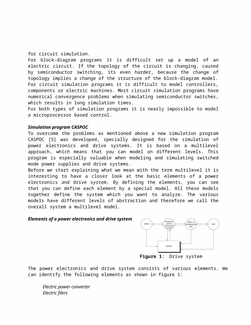
Elements of a power electronics and drive system
The power electronics and drive system consists of various elements. We can identify the following elements as shown in figure 1:
Electric power converterElectric filersElectrical and mechanical load and sourceRegulator or control
All elements influence each others behavior, and therefore it is impossible to analyze the elements separately, to get the overall behavior.The models which describe the elements of the power electronics and drive system have different levels for each element. To model all elements we therefore need a multilevel model.We will start with identifying the different levels for modeling. After identifying the levels we will discuss which modeling methods are necessary for modeling the different levels. We will introduce modeling methods like the Modified Nodal Analysis (MNA) method [4], block diagram and modeling language and describe their usage in the program CASPOC. Also we will discuss some aspects of the program. An example shows the modeling of a voltage source inverter with induction machine.
MULTILEVEL MODELINGWe can define three levels of abstraction where we can model the different elements of the power electronics and drive system. These three levels are:
System levelElectric circuit levelComponent level
Over these three levels we will divide the elements of the power electronics and drive system. We model the power converter as an electric circuit with active and passive components on the electric circuit level. The power circuit consists of components which we model one level lower, on the component level. Examples of components are induction machines, semiconductor switches or a mechanical load which has a connection with an induction machine.
Figure 1: Drive system

On the highest level we can model the regulation or control.Connected to these levels is the level of abstraction. The component level has the lowest abstraction. These models are mostly based on physical relations. The system level has the highest abstraction. Here we can replace a digital or analog control circuitry by a single equation or programming line. The electric circuit level is between the system and component level and is the most studied level in the analysis of power electronics and drive systems.We can not derive one model for all three modeling levels. This is because of two reasons. First the way of defining the model is different per level. Secondly it is more efficient if you model and simulate each level by its own most efficient modeling approach. An example of different modeling approaches is the difference between a netlist of a switched mode power supply and an equation describing a voltage controlled oscillator. In the first approach the netlist describes the components and their interconnections. Using state equations, which was done in [3], or the Modified Nodal Analysis (MNA) method, Ho [4], the program can define a set of equations which solve the nodal voltages and branch currents according to Kirchoffs law. In the second approach a sinusoidal is created with a voltage dependent frequency, which is easily modeled in a block diagram model. Another example is the implementation of a controller. You can describe a digital control by an algorithm, but it is inefficient, if possible at all, to describe this algorithm by lumped circuit elements.
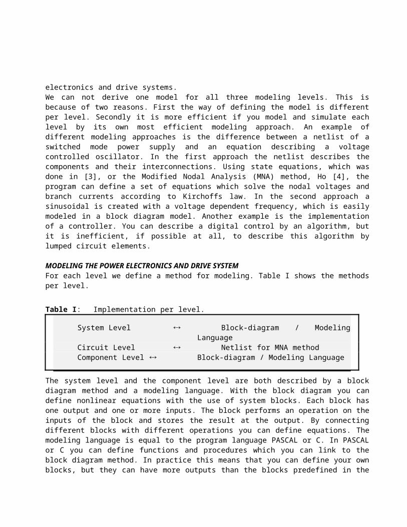
MODELING THE POWER ELECTRONICS AND DRIVE SYSTEMFor each level we define a method for modeling. Table I shows the methods per level.
The system level and the component level are both described by a block diagram method and a modeling language. With the block diagram you can define nonlinear equations with the use of system blocks. Each block has one output and one or more inputs. The block performs an operation on the inputs of the block and stores the result at the output. By connecting different blocks with different operations you can define equations. The modeling language is equal to the program language PASCAL or C. In PASCAL or C you can define functions and procedures which you can link to the block diagram method. In practice this means that you can define your own blocks, but they can have more outputs than the blocks predefined in the block diagram method. Since you can define any structure in PASCAL or C, it enables you to set up algorithms to model a digital regulator or control.We will describe each modeling method in the following sections.
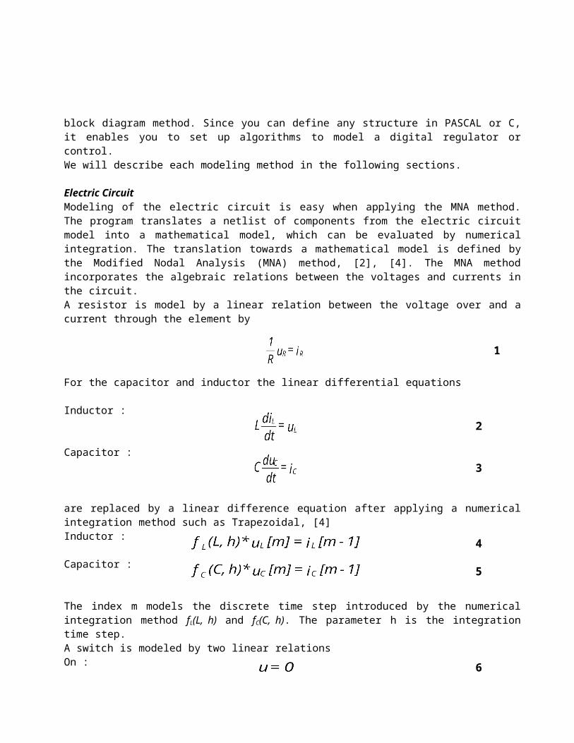
Electric CircuitModeling of the electric circuit is easy when applying the MNA method. The program translates a netlist of components from the electric circuit model into a mathematical model, which can be evaluated by numerical integration. The translation towards a mathematical model is defined by the Modified Nodal Analysis (MNA) method, [2], [4]. The MNA method incorporates the algebraic relations between the voltages and currents in the circuit.A resistor is model by a linear relation between the voltage over and a current through the element by
Table I: Implementation per level.
System Level Block-diagram / Modeling LanguageCircuit Level Netlist for MNA methodComponent Level Block-diagram / Modeling Language
2
3
4
5
6
i=0 7
For the capacitor and inductor the linear differential equations
Inductor :
Capacitor :
are replaced by a linear difference equation after applying a numerical integration method such as Trapezoidal, [4]Inductor :
Capacitor :
The index m models the discrete time step introduced by the numerical integration method fL(L, h) and fC(C, h). The parameter h is the integration time step.A switch is modeled by two linear relationsOn :
Off :
The on relation is modeled by assuming both nodes of the switch are equal to each other and the off relation is modeled by assuming no relation between both nodes of the switch, such that no current can flow between them.According to Kirchoffs laws the sum of the currents flowing into a node equals zero. Summing the currents per node gives a set of equations
Here ij[m] equals the sum of independent currents flowing into node j, uk is the voltage of node k and ajk is a relation between the voltage on node j and node k, defined by relation (1) to (7).In matrix notation (8) is rewritten into
where matrix A defines the algebraic relations between the voltages and currents, x is a vector holding all nodal voltages and b is a vector holding all independent current sources. In the modified nodal analysis method also
1
8
9
the independent voltage sources are included into vector b.The syntax of this netlist is compatible to the syntax defined in SpiceTM. In this netlist you define the connection of electric components like
Xcomponent node1 node2 value
The character X defines the type of the component like capacitor, inductor or diode, etc. The nodes define the connection with other components and value denotes a numerical value or a connection with the component or system level.
Block diagramYou can model the component and the system level with the block diagram method. With the block diagram method you can describe nonlinear Differential Algebraic Equations. Each block represents an operation on its inputs, and stores the result on its output. The block diagram sequentially executes the calculations. CASPOC sorts the blocks such that it can perform the calculations sequentially and replaces integrators by a fourth order Runge Kutta method.The sorting algorithm places all blocks with a memory function at the beginning of the sequence. The memory the block diagram method uses is proportional to the number of blocks. Because of the storage of the blocks in the memory in a sequential way, also the simulation time for the block diagram method is proportional to the number of blocks.
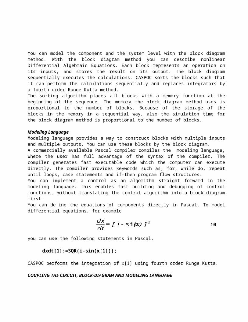
Modeling LanguageModeling language provides a way to construct blocks with multiple inputs and multiple outputs. You can use these blocks by the block diagram.A commercially available Pascal compiler compiles the modeling language, where the user has full advantage of the syntax of the compiler. The compiler generates fast executable code which the computer can execute directly. The compiler provides keywords such as; for, while do, repeat until loops, case statements and if-then program flow structures. You can implement a control as an algorithm straight forward in the modeling language. This enables fast building and debugging of control functions, without translating the control algorithm into a block diagram first.You can define the equations of components directly in Pascal. To model differential equations, for example
you can use the following statements in Pascal.
dxdt[1]:=SQR(i-sin(x[1]));
CASPOC performs the integration of x[1] using fourth order Runge Kutta.
COUPLING THE CIRCUIT, BLOCK-DIAGRAM AND MODELING LANGUAGE
10

The various levels together define the model of the power electronics and drive system. Therefore the three modeling methods need to be connected. Figure 2 shows the interconnection between the three modeling methods. Since the MNA method differs substantially from the block diagram method and the modeling language, you have to define an interface between these modeling methods. The connection between the block diagram and the Modeling Language is straight forward. The block diagram treats the procedures and functions of the Modeling Language like blocks which have the same level of abstraction like the blocks in the block diagram method. The definition of the equations which model the block diagram and the Modeling Language is straight forward, because of the input / output relations of the blocks and procedures. However the connection to the MNA method is more difficult. The MNA methods sets up a set of equations which describe the circuit behavior according to Kirchoffs first and second law. Here the input / output relation is not so clear like the definition of the block diagram method. Controlled devices such as voltage and currents sources or switches define the connection from the block diagram method to the electric circuit. The block diagram can measure voltages, currents and the status of switches from the circuit.
Circuit Block-diagramThe currents and voltages in the electric circuit model are available as signals in the block-diagram model. Using the block voltage, you can measure each nodal voltage, or the difference between two nodal voltages. Using the block current, you can measure the current flowing through a circuit element like a voltage source, resistor, inductor, capacitor, switch, diode, etc. The status of a switching element like for example a diode or a GTO, is measured using the block state. This block generates a logical signal indicating if the element is in conducting or in a blocking status.
Block-diagram CircuitIn the circuit model you can include controllable voltage or current sources. The current or voltage level of such a source is dependent on the value of a signal which is generated in the block-diagram model. To set up a three-phase grid, three sinusoidal waveforms are defined using the block type signal and the outputs of these blocks are directly used as voltage level.Signals from the block-diagram control the switching elements like the switch, GTO or SCR. The gate signal supplied to the switching element has an idealized function. It only turns on or off the switching element.The value of a linear element, like a resistors, inductor or capacitor can be changed using the block ChangeE. Doing so a piecewise-linear element can be created. A non-linear inductor is created by assigning the value of the inductor to the output from a block in the block-diagram.
Modeling Language Block-diagramUsing the modeling language you can create procedures which you can use as Multi Input Multi Output (MIMO) blocks in the block-diagram. The MIMO blocks build by using PASCAL or C have to be compiled into a Dynamic Link Library (DLL). Modeling language MIMO library blocksA DLL is an executable program which can be used as a block in the block-diagram. Such a DLL only contains a program and therefore it can be included many times in the block-diagram. It is connected in the block-diagram using the block UserDLL. The inputs of this block are directly available inside the program of the DLL. Output of the DLL program is accessible in the block-diagram as the output from the UserDLL block. Only a small number of variables is allowed for the communication between the block-diagram and the
Figure 2: Coupling of the models
modeling language.Modeling language for large designsNext to using DLL's, you can connect one large modeling language program to the block-diagram. This is valuable if a large controller has to be defined, with a large amount of variables. The predefined blocks FromML and ToML are used to make a connection between the block-diagram and procedures defined in the modeling language. You can exchange variables via an array of type real, called the bus.

Machine modelsFor an induction machine and a DC machine, predefined models are included in the block-diagram. The electrical terminals of these machines are connected in the circuit model. The mechanical section of these machines, the electric torque, is available as signal in the block-diagram. From this signal the angular speed can be calculated, using an equation modeling the mechanical behavior of the machine and the load.More complicated machine models can be included by defining the modeling partly in the block-diagram and partly by using modeling language. The electric terminals of the model are inserted in the electric circuit model and in this way the electrical and mechanical variables are combined into one simulation. The electrical variables are influencing the behavior of the electric circuit. The mechanical variables are necessary for proper modeling of the electric machine, for example the position in a Switched Reluctance Machine (SRM).
Device models
Non-linear device models can be defined in the block-diagram or the modeling language. Using controllable sources it is possible to model, for example, the reverse recovery of a diode. The model presented in [10] is included as an example of semiconductor modeling in the student version. The equations for the reverse recovery of a diode are modeled as a modeling language MIMO block and compiled into a DLL.
Digital or analog controllersThe modeling language is extremely powerful when modeling digital controls[6], [7]. In many cases it is even possible to use the same program for the modeling language as can be used in a microcontroller. Since you can use any commercially available compiler, as long as it provides DLL's, you are free to choose the programming language for your modeling language program, for example PASCAL or C. In PASCAL or C it is very simple to use algebraic or matrix operations to define a field oriented controller. All possible transformations can be included into the modeling language. Controllers for DC converters are getting more complex due to the introduction of quasi-resonant converters and soft switching. Especially for zero voltage or zero current or multi resonant converters the block FFLT is designed, which enables the design of a simple controller for resonant converters. This block enables you to model all kinds of resonant converters in the student version.
SIMULATIONIn CASPOC two numerical methods are used for the numerical integration of the differential equations in the
Figure 3: Machine model
Figure 4: Reverse recovery diode current

models. The differential equations for the inductors and capacitors in the circuit model are numerically integrated using the trapezoidal method. This method is enhanced to make it numerically robust because of all the switching actions in the circuit.The integrators in the block-diagram and the modeling language are numerically integrated using the Runge Kutta 4th order method.The main problems in circuit simulation are caused by the switches. In CASPOC the numerical methods are enhanced to avoid these problems. The first problem is caused by turning a switch off due to a zero crossing of an inductor current. SpiceTM
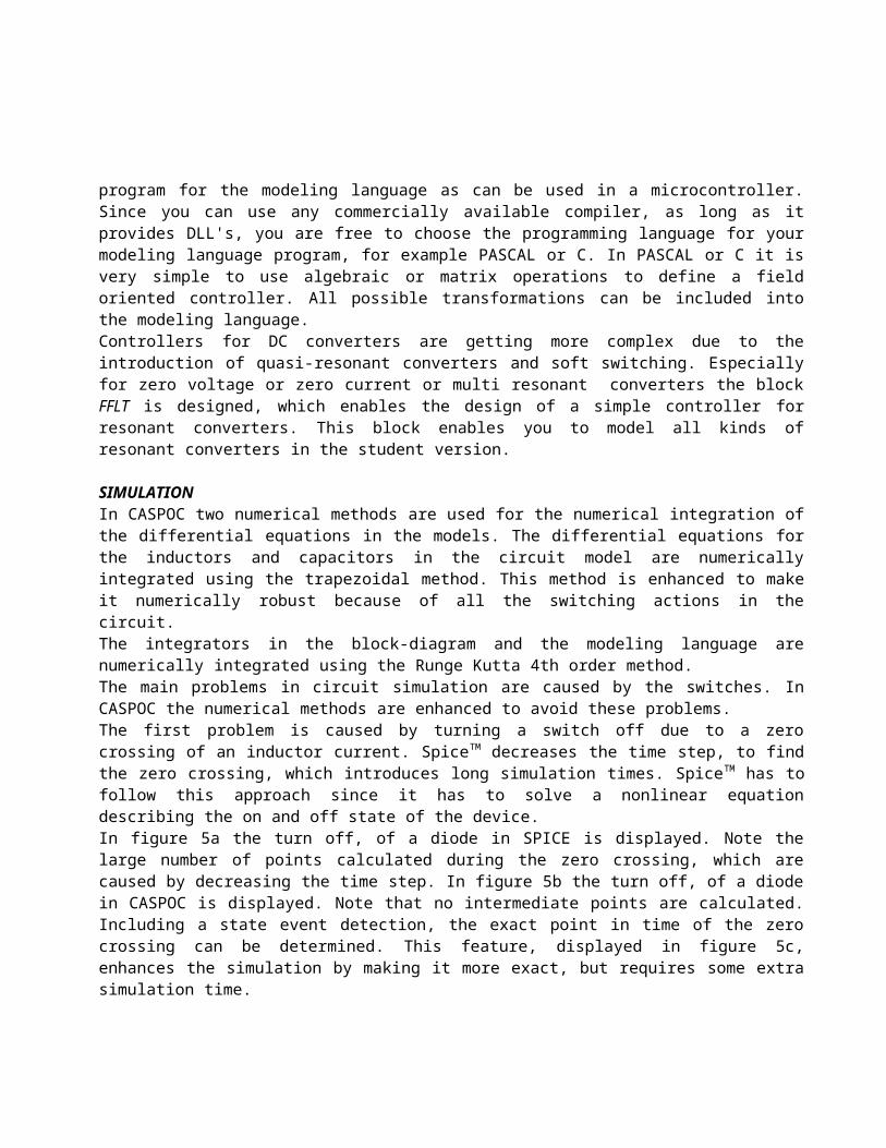
decreases the time step, to find the zero crossing, which introduces long simulation times. SpiceTM has to follow this approach since it has to solve a nonlinear equation describing the on and off state of the device.In figure 5a the turn off, of a diode in SPICE is displayed. Note the large number of points calculated during the zero crossing, which are caused by decreasing the time step. In figure 5b the turn off, of a diode in CASPOC is displayed. Note that no intermediate points are calculated. Including a state event detection, the exact point in time of the zero crossing can be determined. This feature, displayed in figure 5c, enhances the simulation by making it more exact, but requires some extra simulation time.By using switch models to model the semiconductor devices, CASPOC avoids the decrease of the step size to find the solution. Because of the switch models, CASPOC is able to simulate three phase AC-AC converters, like for example a cycloconverter with sort simulation times [9]. The difference in simulation time is explained more in detail in [8], where a simulation of a buck converter with PID controller using CASPOC is compared to a simulation using SPICE. The difference in simulation time, 300 seconds for SPICE against 10 seconds for CASPOC, is mainly caused by the semiconductor models.The second problem is the series connection of two inductors, which can occur because of the switching operation. Since this series connection gives a stiff differential equation, where two different currents have to be modeled as one, the program should have facilities to calculate this current. CASPOC calculates the current through both inductors without changing the topology from two inductors to one inductor. It also treats the sudden parallel connection of capacitors and / or voltage sources in the same way.
USER INTERFACEThe input for the program is done via text files. The model for the electric circuit is compatible to the SPICE input format. Special elements and commands are added to this syntax, for example the communication with the block-diagram.The modeling language, for example PASCAL or C, has to be compiled into a Dynamic Link Library (DLL). The defined DLLs are linked to the program during the simulation.The program has a graphics user interface, so the user doesn't need to know any commands. All parameters and variables of the model and the simulation are accessible in menu's during simulation. This makes the program completely interactive for the user. During the simulation the calculated waveforms are directly drawn on the screen. You can interrupt the program to alter parameters or variables and continue the simulation. The impact of changing variables and parameter on the model can be seen directly on the screen.A special block ShowCon can be defined in the block-diagram, which gives a constant signal. During simulation the value of this block is displayed on the screen and the user can change its value by selecting the block on the screen during simulation. This is valuable for demonstrations, where one or more parameters influence the simulation. For example the firing angle of a three phase rectifier can be defined by a ShowCon block. The
Figure 5: Zero crossing; a)Spice. b) CASPOC. c) CASPOC with State Event

influence of the firing angle on the output voltage is explained easily during classroom demonstrations.The output of the program are graphical waveforms on a screen, numerical results in text files, or a hardcopy for a printer or a plotter. A HPGL file can be generated which contains the screen image. This HPGL file can be used in word processors for documentation.
TOOLSSeveral tools are included in the program CASPOC. They are special for power electronics or drive systems.
Harmonic components
Figure 6: Harmonics with IEC Limit
In CASPOC the harmonic content of a current, voltage or other signal can be evaluated using a Fast Fourier Transform (FFT) algorithm. An important question in todays design is limiting harmonic currents. There are a number of standards concerning the limits of harmonic currents. For example the IEC-555 deals with the limitation of harmonic currents injected into the public supply system. It specifies limits of harmonic components of the input current which may be produced by an equipment tested under specified conditions. This standard is applicable to electrical and electronic equipment having an input current up to 16 amperes per phase and intended to be connected to public low-voltage distribution systems. The limits for this standard are supplied to the program in a text file and are displayed in the same window where the harmonic components of a current are displayed, see figure 6.
Arrows or phasorsIn CASPOC you can display arrows which represent a phasor or a vector in a two dimensional plane. For example the or dq coordinates of a Park transformation or two dimensional variables in field oriented controllers can be displayed dynamically, while they can change in size and direction. The representation of
a three phase system is shown in figure 7. For three phase systems or for 50 Hz components, phasor diagrams can be constructed, which gives insight in the steady state operation of an electrical system.
RMS, average and power factor
Figure 7: Phasors
Using blocks like; RMS, Average or PF, you can calculate the RMS or average value or the power factor of a current, voltage or signal during the simulation. The output from these blocks can be displayed directly on the screen or used as a signal in the calculation.A harmonic component of a current, voltage or signal can be calculated using sin, cos and integrator blocks. This is valuable when constructing phasor diagrams of one-phase AC electric circuits. Using arrows, you can immediately display the results of this calculation on the screen and see how the phasors are changing dynamically.
EXAMPLE VOLTAGE SOURCE INVERTER
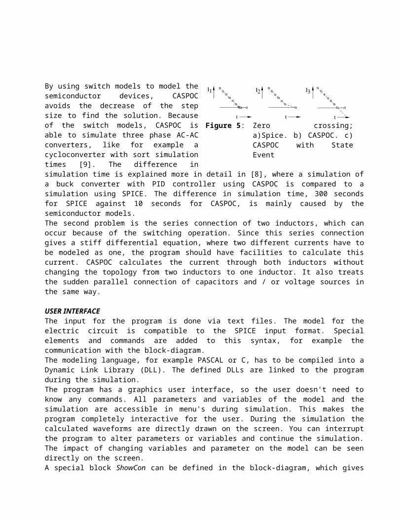
In this example the modeling and simulation of a voltage source inverter drive as shown in figure 8 is explainedTo model the drive, three levels are used. At the circuit level the voltage source inverter is modeled. The induction machine is modeled at the component level, the control is modeled at the system level and the load of the machine is modeled at component level. The modeling of each distinct element of the drive will be examined more in detail, where for each element the used type of modeling is explained.
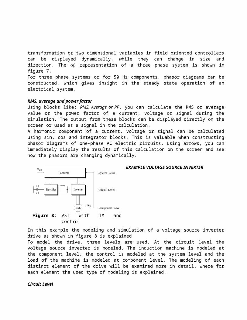
Circuit LevelIn the model of the drive the switches are assumed to be piecewise-linear. The voltage source inverter is modeled in a circuit model, see figure 9. It includes the main grid, modeled by a series connection of a voltage source, the grid impedance and inductance, a rectifier to provide a DC voltage, a DC link consisting of LLink and CLink and the inverter build from GTOs and diodes.
The snubber circuits are omitted in this model, because their influence on the overall dynamic behavior of the drive is smaller compared to that of the system dynamics introduced by LLink, CLink and the induction machine. The set up of a circuit model is very straightforward. Per element in the circuit the nodes of the element are specified and the default value for the element is given. The interconnection between the elements is defined via the specified nodes.Not all parameters of the circuit are defined in the circuit model. The voltages of the main grid, the control signals for the GTOs and the connection of the induction machine to the circuit are defined at another level, the system and component level, and modeled in a block-diagram and the modeling language.
Figure 8: VSI with IM and control
Figure 9: Circuit model of the rectifier, DC link and inverter

Component LevelAt the component level the main grid, the induction machine and the load of the induction machine are modeled. The main grid is modeled by three sinusoidal waveforms which are represented by three blocks in the block-diagram model.The induction machine is modeled at the component level by a set of non-linear equations, which are included into one block ASMSC.
where the fluxes of the machine are presented by
and the torque Te produced by the machine is given by
The load of the induction machine is modeled at the component level. Only the friction and the inertia of the load are modeled given by
This equation is modeled in a block-diagram model shown in figure 10.
11
12
13
14

System LevelThe regulation of the drive is modeled at the system level by computer program instructions. From the reference angular position angle the status of the GTOs is examined by simple IF-THEN relations.Using the computer program instructions any control method for the GTOs can be applied. In this example a six pulse block modulation is performed, with a notch in the center of each block, in order to cancel the third harmonic in the machine. Also the notches are programmed using the IF-THEN relations in the computer program instructions. The firing signals for the GTOs are in this way defined as boolean signals. The interaction between the GTOs and the boolean control signals is only performed by the turn on and turn off of the GTOs. The dynamic behavior of the gates of the GTOs is not included in the modeling. They are assumed to be small compared to the dynamics caused by the inverter and the induction machine.The computer program instructions are evaluated during simulation. If the used programming language is transportable, which is the case with languages such as C and Pascal, the computer program instructions which are included in the model can directly be used in a digital controller. The debugging of this model can take place on basis of the simulation, whereafter the model can be implemented in the hardware of the digital controller which is used for the drive system. In this way a one to one relation is used for modeling the control of drive systems.
Results simulation VSI driveThe results from the simulation are compared with an experimental set up and displayed in figure 11 for the simulation and figure 12 for the experimental results. Both figures show the input voltage and current for one phase of the rectifier, the DC link voltage and the inverter voltage and current for one phase.
CASPOCThe program is available for PC-Dos based computers. The input of the program are ASCII files where you define the electric circuit, the block-diagram and the modeling language. During simulation you can stop the program and make alternations in your implementation. Doing so you can study the effect of parameters in your implementation. Since the program works interactive, results are immediately shown on your screen. Because simulation times are low, multilevel implementation and switch models, you are able to study the large signal behavior of a system for more than one period of operation. Using a commercially available compiler, you can compile the modeling language to a Dynamic Link Library (DLL), which the computer can execute faster than interpreted code. The conversion of your model by a compiler to machine language is more efficient than interpretation of code, which is the case in a block diagram.Special attention is given to the simulation time, which should be as low as possible. This enables you to verify and test many features of your design.
Figure 10: Block-diagram model of the IM with mechanic load.
Student versionA student version is available which can simulate a limited circuit and block-diagram. However the version is large enough to model DC, resonant, AC converters, three phase rectifiers, inverters or even voltage source inverters coupled to an induction machine. These examples are supplied with the student version [5].
ExamplesFor educational purposes a workbook with a large collection of examples is available[5]. All kind of basic models of power electronic circuits and drive systems are included as an example. The workbook shows the schematic of the model and an overview of the circuit and block-diagram model. Questions concerning the example are included, together with a hardcopy of the screen showing the simulation. It is intended for education in power electronics and the majority of the examples works with the student version.
CONCLUSIONSThe program CASPOC is especially designed for modeling and simulation of power electronic circuits and drive systems. It includes models for the induction and DC machine and has special blocks for calculating the RMS and power factor of currents and voltages. Ideal semiconductor models are included, which account for shorter simulation times than other general simulation programs.Modeling and simulation of power electronics and drive systems involves two major problems. First, the semiconductor switches introduce large simulation times. Second, there are different models for the components of a power electronic circuit or a drive system.In CASPOC the first problem is solved by introducing ideal semiconductor models and applying state events to reduce the simulation time during the turn-off at zero crossings of semiconductor switches. The second problem is solved by applying a multilevel model, which includes a circuit model, a block-diagram model and modeling
Figure 11: Simulation Figure 12: Measurement
language (Pascal or C). The IEC-555 standard and other standards on limiting harmonic components are included in the integrated FFT program which calculates harmonics of currents, voltages or signals.A student version for educational purposes and a workbook containing a large amount of models of basic power electronic circuits and drive systems are available.
LITERATURE
[1] G.A. Franz, "Multilevel simulation tools for power converters", IEEE APEC CH2853-0/90/0000-0629, 1990.
[2] C-W. Ho, A.E. Ruehli, P.A. Brennan, "The modified nodal approach to network analysis", IEEE Transactions on Circuits and Systems, Vol CAS-22, No 6, June 1975.
[3] C.J. Hsiao, R.B. Ridley, H. Naitoh, F.C. Lee, "Circuit oriented discrete-time modeling and simulation for switching converters", IEEE 0275-9306/87/0000-0167, 1987.
[4] A.F. Schwarz, "Computer-aided design of microelectronic circuits and systems, Vol 1", Academic press 1987.
[5] "CASPOC User's manual", Simulation Research, P.O.Box 397, 2400 AJ, Alphen a/d Rijn, The Netherlands. Telephone : +31 172092353
[6] H. Polinder, N.H.M. Hofmeester, L.J.J. Offringa, W. Deleroi, "Cycloconverter for high speed permanent magnet generator units", Proceedings EPE Brighton, 1993.
[7] P. Bauer, J.B. Klaassens, "A novel control principle for parallel resonant voltage link converters", Proc. IEEE IAS annual Meeting, Huston, October 1992.
[8] P.J. van Duijsen, "Multilevel modeling and simulation of electronic circuits and systems", Proceedings PE&ED Košice, CSFR 1992.
[9] P.J. van Duijsen, "Multilevel modeling and simulation of power electronic systems", Proceedings EPE Brighton, England 1993.
[10] P.O. Lauritzen, C.L. Ma, "A simple diode model with reverse recovery", IEEE Transactions on Power Electronics, Vol 6 No 2, April 1991.